save this manual
TRANSCRIPT

CLASSIC®
OUTDOOR WOOD FURNACE
OWNER’S MANUAL
Save This ManualFor Future ReferenceBeaverton�
Oregon USA
OMNI-Test Laboratories, Inc.
Tested &�Listed By
C US

2
The Classic®
by
Central Boiler, Inc.20502 160th Street
Greenbush, MN 56726www.centralboiler.com
The Central Boiler Classic Models CL 4436, SCL 5636,CL 5648, and SCL 5648 are either UL or OMNI tested andlisted.
INTRODUCTIONLabeling and Terminology
The wood furnace and this manual use the followingterms and symbols to bring attention to the presence ofhazards of various risk levels and important informationconcerning the use and maintenance of the wood furnace.
WARNING: Indicates presence of a hazard which cancause severe personal injury, death, or substantial propertydamage if ignored.
CAUTION: Indicates presence of a hazard which willor can cause minor personal injury or property damage ifignored.
NOTE: Indicates supplementary information worthy ofparticular attention relating to installation, operation, ormaintenance of the wood furnace but is not related to ahazardous condition.
Be sure to follow all instructions and related precautionsas they are meant for your safety and protection. Store thismanual in a readily accessible location for future reference.Foreword
This manual is to be used as a guideline for installation,operation, and maintenance of the Classic outdoor woodfurnace. This manual is organized into six sections for youreasy reference.
Section 1 relates to Operation;Section 2 relates to Maintenance;Section 3 relates to Installation;Section 4 relates to Troubleshooting;Section 5 relates to Owner Serviceable Items;Section 6 includes General Information.Anyone owning or operating this furnace must read, fully
understand, and follow all of the information in this manual.With proper maintenance, the Classic outdoor wood furnace
will give many years of service; however, if replacement ofany component is desired, be sure the furnace has cooled priorto starting the replacement procedure. Also, all live coals shouldbe removed from the firebox before performing anymaintenance that requires the draining of water.
WARNINGBe careful when performing maintenance on thefurnace prior to it being thoroughly cooled down.Disconnect the electrical power to the furnace andremove all live coals from the firebox beforeperforming maintenance that requires the drainingof water or replacement of an electrical component.
Wood Quality and StorageIt is always best to burn seasoned wood. Seasoned wood
burns more efficiently and minimizes the amount of creosoteformation. Wood should be stacked so that both ends areexposed. Covering the wood to keep it out of the elementswill keep it from absorbing moisture.
CAUTIONDo not store wood within the installationclearances listed with this manual.
INSTALLATIONS IN MASSACHUSETTS1. All installation components must be products approved
in the Commonwealth of Massachusetts by the Gasand Plumbing Board.
2. Maximum run of tubing from water heater to fan coilis 50 linear feet.

3
Table of ContentsINTRODUCTION ........................................................................................................................................................ 2
Labeling and Terminology ..................................................................................................... 2Foreword ............................................................................................................................... 2
SECTION 1 - OPERATING INSTRUCTIONS ......................................................................................................... 4OPERATING CLEARANCES AND PRECAUTIONS ........................................................................... 4FIRING THE FURNACE ...................................................................................................................... 4
Filling the Firebox .................................................................................................................. 4Adjusting Water Temperature ................................................................................................ 5
CONTROL LOCATIONS ..................................................................................................................... 5SECTION 2 - MAINTENANCE INSTRUCTIONS .................................................................................................. 6
FIREBOX MAINTENANCE .................................................................................................................. 6MAINTENANCE SCHEDULE .............................................................................................................. 7WATER QUALITY AND MAINTENANCE ............................................................................................ 7POST HEATING SEASON MAINTENANCE ....................................................................................... 8
SECTION 3 - FURNACE INSTALLATION ............................................................................................................. 9INSTALLATION CLEARANCES AND PRECAUTIONS ...................................................................... 9PLANNING THE INSTALLATION ........................................................................................................ 9GENERAL INSTALLATION INFORMATION ..................................................................................... 10WATER SUPPLY LINES AND INSULATION .................................................................................... 11
General Information ............................................................................................................. 11Installing .............................................................................................................................. 14Wiring The Circulation Pumps ............................................................................................. 15
WATER HEATER INSTALLATION .................................................................................................... 15EXISTING FORCED AIR INSTALLATION ........................................................................................ 16HEATING MULTIPLE ZONES OR BUILDINGS ................................................................................ 19HYDRONIC INSTALLATIONS ........................................................................................................... 20
Vented System Installation .................................................................................................. 20Pressurized Water System Installations .............................................................................. 21Direct Circulation Baseboard Installation ............................................................................ 23Radiant Floor System Installations ...................................................................................... 24High Volume Water Heating ................................................................................................ 26Pool And/Or Hot Tub Heating .............................................................................................. 27
FINALIZING THE INSTALLATION .................................................................................................... 28INITIAL START-UP PROCEDURES ................................................................................................. 28
SECTION 4 - TROUBLESHOOTING .................................................................................................................... 30SECTION 5 - OWNER SERVICEABLE ITEMS ................................................................................................... 32
CIRCULATION PUMP ....................................................................................................................... 32SOLENOID ........................................................................................................................................ 32TEMPERATURE CONTROLLER ...................................................................................................... 32WATER TEMPERATURE SENSOR ................................................................................................. 33
SECTION 6 - GENERAL INFORMATION ............................................................................................................ 34WIRING DIAGRAMS ......................................................................................................................... 34PARTS LISTING, CL 4436 ................................................................................................................ 35PARTS LISTING, CL 5636 ................................................................................................................ 36PARTS LISTING, CL 5648 & SCL 5648 ............................................................................................ 37FURNACE MEASUREMENTS .......................................................................................................... 38INSPECTION RECORD .................................................................................................................... 391 YEAR LIMITED WARRANTY ..................................................................................... BACK COVER

4
FIRING THE FURNACEThe furnace comes equipped with a digital temperature
controller which controls the water temperature at whichthe furnace damper shuts down. The controller allows thefurnace to operate with a water temperature within a rangeof 150-195° F.
CAUTIONCHECK WATER LEVEL! Be sure water is at theFULL mark before firing.
CAUTIONIf the furnace boils hard, be sure to check the waterlevel and restore to the correct level if needed. AddCorrosion Inhibitor as needed.
The first time you fire the furnace, place dry kindlingwood near the middle of the firebox. Use a small amount ofpaper to light the fire. Add larger pieces of wood to the firebut do not fill the firebox completely. When the watertemperature reaches the controller setting (185° F) and thedamper closes, let the furnace cycle a few times to be sureit is operating properly; then the furnace may be filled withmore wood. After a few days of operation you will begin toknow how much wood is needed each day. If you only fillthe amount needed, it is easier to stir the ashes along thesides of the firebox and pull them forward (see FireboxMaintenance).NOTE: Be sure to clean and inspect the firebox asoutlined in Section 2, Firebox Maintenance.
CAUTIONFailure to clean the firebox as indicated will resultin accelerated corrosion.
Periodically during the normal operation of the furnace,look at the water temperature display on the furnace. Itshould read the same temperature as the controller setting(185° F). If the reading is 212° F or above, this indicateseither a low-water condition or a malfunctioning temperaturecontroller or snap disc (unless the door and/or damper areopen or not sealing properly). If the condition persists andthe water level is correct, call your dealer for service.
Filling the FireboxPrior to filling the firebox with wood, always pull the
hot coals forward to the draft area (front and center of thefirebox). When hot coals are pulled to the draft area beforefilling wood each time, the added wood ignites faster as thecombustion air is forced through the hot coals and into thenewly added wood. If the coals are pushed to the back, aless efficient burn will result. If needed to extend the burntime, the furnace may be completely filled.
When filling the firebox with wood, use the followingprocedure.1. Unlatch the door; then as the door is opened, step back
from the furnace. From a distance, observe the fuelload. Stay as far away from the furnace as possibleespecially if large amounts of wood and coals arepresent.
Section 1 - Operating Instructions
OPERATING CLEARANCES ANDPRECAUTIONS
Please read and observe the following informationcarefully before operating the Classic outdoor wood furnace.
WARNINGNever fire the furnace if the water level is belowthe FULL mark.
1. The Classic is to be fueled with untreated wood only.Do not burn garbage, gasoline, rubber, engine oil,naphtha, plastics, treated wood, or combustibles otherthan wood.
2. Do not use chemicals or fluids to start the fire. Useonly paper and kindling to start an initial fire. Existingcoals left in the firebox will restart the fire afterreloading the furnace.
3. Do not store wood or other combustibles within theinstallation clearances listed in Section 3. Be sure toleave a safe amount of room to load the firebox andclean out ashes without causing a fire hazard. Keepthe area around the furnace clear of combustiblematerials. For fire safety, we recommendmaintaining a 6 foot clearance to all combustiblematerials especially around door and draft areas.Debris of wood chips and other combustibles inthe loading area may very easily be ignited if ahot coal is spilled out of the firebox and leftunnoticed.
4. This furnace is not to be used with an automatic stoker.5. The furnace must not be allowed to pressurize. The
vent cap is to be inspected periodically for anyobstructions or restrictions. The vent cap must fitloosely over the vent. Do not extend or connectanything to the vent pipe.
Fig. 1
6. All cover plates, enclosures, and guards must be securedat all times except during maintenance, inspection,and servicing.
7. When replacing a light bulb, use a 40 watt appliancebulb. Do not install a bulb in excess of 60 watts.
8. In case of a power outage, either a small generator or12V battery and a power inverter can maintain enoughelectricity to operate the system.
9. If any questions should arise that cannot be answeredby the information in this manual, be sure to contacteither your dealer or heating contractor.
SECTION 1 - OPERATING INSTRUCTIONS

5
Section1
CAUTIONStay as far away as possible from the door areawhen opening the door.2. If necessary, clean the firebox of excess ashes and/or
crusty deposits.3. Pull the hot coals to the draft area of the firebox.
Fig. 2
4. Load the firebox with wood being careful not to bepinched between the wood and any part of thefurnace.
NOTE: Use extreme care if adding wood when alarge amount of wood and coals are alreadypresent in the furnace as very hot gasses will becoming out of the firebox door.
WARNINGWhen filling wood into the firebox, be careful notto get pinched between the wood and the doorframe or any part of the furnace. Use extreme careas large pieces of wood are difficult to handle.
5. Close and secure the door. Do not use the door toram wood into the furnace. Do not operate thefurnace with the door open. If the door is left open,an uncontrolled burn will result. To return to acontrolled burn, close and secure the door.
NOTE: Creosote is an accumulation of combustionby-products on the surfaces of wood burningappliances. Twice a month during the heating season,inspect for excessive creosote buildup on the walls,flue, and chimney; if present, it should be removedfor proper operation and fire safety. Creosote if ignitedin the chimney, results in an excessively hot chimneyfire. In case of a chimney fire, close the door.
Fig. 3
Adjusting Water TemperatureThe furnace high water temperature setting can be
adjusted anywhere within a temperature range from 150 -195º F. At 10º F less than the temperature setting (10º F beingthe thermostatic differential), the controller will start thedraft cycle by opening the damper (and activating theoptional draft inducer if equipped). The controller has beenpreset at the factory at 185º F. When OUT is indicated onthe display, the controller is calling for heat. If it is desiredto change the setting (because of a higher than normal heatload or cooler weather) use the following procedure.NOTE: It is not recommended to set the controllerbelow 165º F.1. Press the SET button on the controller. “SP” will appear
on the display.2. Press SET again. The set temperature will now be
displayed. The factory preset temperature is 185º F.3. Press either the UP or DOWN button until the desired
operating temperature is reached.4. Press SET to save the setting. “SP” will appear.5. To exit the programming mode, either press the SET
and DOWN buttons at the same time or wait oneminute and the controller will automatically exit theprogramming mode.
NOTE: The controller will only allow valuesbetween 150 and 195º F.CONTROL LOCATIONS
Fig. 4
Section 1 - Operating Instructions
6
FIREBOX MAINTENANCENOTE: Proper firebox maintenance will have directeffect on the life of the furnace.
CAUTIONDo not burn plastic, garbage, or treated wood.
NOTE: Chloride or sulfurous gasses generated ifplastic or rubber is burned will mix with themoisture from the wood and form sulfuric orhydrochloric acids in the firebox creatingexcessive corrosion.
It is important to stir the ashes in the firebox and pullthem forward once every three or four days to prevent theashes from sealing moisture on the bottom and along theedges. It is especially important to scrape the walls and thefour corners at the ash line and below. If this maintenanceoperation is not performed as directed, deterioration canresult from moisture trapped between the ashes and the steel.
Once each day, apply Ashtrol Conditioner to the firebox.Use a spoon as directed to broadcast powder in firebox,alternating placement daily. One day broadcast on fire orhot coals, the next day broadcast against the walls and baffle.Ashtrol is a pH modifier that helps to neutralize acids thatmay form in the firebox.
Any heavy or solidified ashes should be removed. Whenthe ashes build up either to the door frame in the front or tothe top of the beveled ash pan of the firebox, they should beremoved. A hoe, ash rake, and shovel to be used for thisprocedure may be purchased from your Central Boilerdealer. Leave enough ashes and coals to relight the fire. Foryour protection, wear a dust mask and protective clothingwhen cleaning ashes from the firebox.
CAUTIONAlways wear a dust mask and protective clothingwhen cleaning ashes from the firebox.
When the ashes are cleaned out, be sure to put them in anoncombustible container with a tight cover. It can takemany days before they are completely cooled down. Otherwaste should not be placed in this container. Each time theashes are cleaned out, inspect the door rope to make sure itis sealing properly.
WARNINGWhen cleaning the furnace, be careful not to spillany coals outside of the noncombustible container.
Once a month the bottom 12 inches of the firebox shouldbe scraped clean. This can be accomplished by letting thefire get very low; then moving the coals to one side and,using a hoe, cleaning half of the firebox. Next, move thecoals to the other side and finish cleaning the firebox leavingsome ashes with the live coals. Finally, pull the coals andashes to the draft area (front and center of the firebox). Whenthe furnace is filled, the coals left in the firebox will lightthe fire.
The top and walls of the firebox above the ash line shouldbe scraped clean if large, thick, or dry crusty deposits arepresent on the walls or behind the baffle. A thin, tar-likelayer of creosote does not cause any problems in theoperation of the furnace. If the flue passageway behind thebaffle becomes plugged, it must be cleaned. Inspect thechimney; clean if an excessive buildup of creosote is present.The ash line and below needs to be cleaned to reduce thepossibility of corrosion.
Inspect the firebox for signs of corrosion every 3 monthsthe first year and every 6 months thereafter. Clean fireboxwalls, front and back corners; then inspect the firebox. Ifexcessive corrosion is visible, review your maintenanceprocedures and monitor quarterly (see MaintenanceSchedule).
Periodically, lubricate door handle with a light petroleumdistillate (WD-40 or equivalent).
SECTION 2 - MAINTENANCE INSTRUCTIONS
Section 2 - Maintenance Instructions

7
MAINTENANCE SCHEDULEDaily – Broadcast Ashtrol in firebox. Alternating each day, apply once per day on
the fire then against walls and baffle. Stir, scrape, and pull ashes in fireboxforward, especially in the back corners. Check water level. Be sure to closethe sight-gauge valve after checking water level.
Monthly – Check door rope; check chimney; check vent cap; remove ashes and cleanfirebox.
Biannually – Complete ash removal and firebox inspection; then scrape the firebox.This biannual inspection should be performed on new furnaces after thefirst month and after the third month of operation. Use a wire brush andsmall scraper to clean firebox, side wall, back wall and ash pan; then usinga light, inspect for corrosion. Lubricate solenoid plunger with a lightpetroleum distillate (WD-40 or equivalent).
WATER QUALITY AND MAINTENANCEAn important part of furnace maintenance is controlling
the quality of the water in the furnace. Central Boilersupplies a pH tape and a nitrite test kit with each new outdoorwood furnace.
Before filling the furnace with water, a sample of thesupply water that will be used to fill the furnace (softenedwater is best if possible) should be tested with the pH tape.This is a simple test in which a small sample of the water iscollected in a clean container; then dip the pH indicatortape in the water and compare the color to the chart providedwith the test paper. If the pH test results indicate a pH levelbetween 6.5 and 8 and there are no other known water qualityproblems, then the furnace may be filled with this water. Ifthe water to be used to fill the furnace has a pH level of lessthan 6.5 or greater than 8, a sample of this water should besent to a water quality test lab for recommended treatment,the water should be conditioned, or water should be suppliedfrom a different source.
Central Boiler Corrosion Inhibitor (p/n 165) givesoptimum protection with an initial treatment of 2000 ppmand a maintenance level between 1500 and 2000 ppm.Corrosion Inhibitor should be added through the vent pipeat the top of the furnace at the recommended rate for eachfurnace. The recommended initial treatment rate for eachfurnace is specified by units. One unit of the CorrosionInhibitor is a 3-quart container. The normal rates for theinitial treatment of the furnaces are as follows: CL 4436—1 unit, SCL 5636 — 1 ½ units, CL 5648 and SCL 5648 — 2units.
Immediately after adding Corrosion Inhibitor, fill thefurnace to the FULL mark on the sight gauge; then start thepump(s). Circulate water for 24 hours and test inhibitor andpH levels using the appropriate test kit. Use Test Kit, p/n405 when no antifreeze is present in the water. Use TestKit, p/n 597, when antifreeze has been added to the water.If the nitrite level is not at least 2000 ppm, add ½ unit of p/n 165; then circulate water for 24 hours and repeat procedureuntil the 2000 ppm level is achieved. Do not exceed 3000ppm. After the proper nitrite level has been obtained, checkpH to make sure it registers between 8 and 9.5.
NOTE: If the system has a larger than normal watercapacity, more inhibitor should be added at arecommended rate of one unit per 180 gallons ofwater.
Before collecting the sample, drain about a quart of waterfrom the sight-gauge tube and then carefully fill the samplecontainer without contaminating the sample. It will benecessary to remove the tube from the sight-gauge mountingclip and bend the tube away from the furnace to collect thesample. Be sure to properly install the sight-gauge tube andclose the valve when finished. The sight-gauge valve andtube will drain when the valve is closed.
The water, once treated, should remain stable as long aswater is not added to the furnace. If water is added to thesystem, the system water should be tested and CorrosionInhibitor should be added (if necessary) to maintain the samelevel of protection.NOTE: Water should not be added to the furnacefrequently as it may increase the amount of solidsin the system that can cause problems in the waterjacket. If there is a leak in the system or if thefurnace is boiling frequently causing an abnormalwater loss, the problem should be identified andrepaired immediately. Under normal operation, onlya small amount of water should need to be addedonce each year or two.
After the initial three months of operation and every sixmonths thereafter, the water should be tested for the pH andnitrite levels. These levels should be maintained as indicatedin the following chart.
Section2
Section 2 - Maintenance Instructions

8
POST HEATING SEASONMAINTENANCE
The water should be left in the furnace during thenon-heating season. Check pH and nitrite as described inthe Water Quality and Maintenance section; add CorrosionInhibitor (p/n 165) as needed. If Corrosion Inhibitor is added,run the circulation pump for two days to thoroughly mix inthe new corrosion inhibitor. If water is added, bring the waterup to operating temperature as soon as possible.
At the end of the season, clean all the ashes out of thefurnace. Scrape the walls and floor of the firebox takingspecial care to clean at the ash line and below, especially inthe corners. Check behind the baffle and in the chimneyflue. Clean out any excessive buildup. Any large or drycrusty deposits on the walls, baffle, or heat exchanger areashould be removed. A thin, tar-like coating of creosote abovethe ash line does not need to be scraped clean as it workslike a protective coating on the metal. When cleaning thefirebox, be sure to wear eye protection and a dust mask.
When the furnace is clean, carefully inspect the fireboxfor any excessive corrosion or deterioration. If any corrosionor deterioration is found, call your dealer. It is always betterto do furnace maintenance during the non-heating season.After the inspection is completed, apply a thin coat of motoroil to the firebox being sure to work oil into all corners.Place a cover over the chimney to keep rain from enteringthe furnace. Clean and oil the chimney flue to the firebox.
Once every three years, the water should be flushed fromthe system and the water jacket should be rinsed (see Fig.5). Remove the inspection panel and insulation coveringthe drain to gain access to the drain. Open the drain; thendrain and flush the furnace. Close the drain securely afterflushing the furnace. Check the drain for leaks after fillingthe furnace with water being certain to treat with the correctamount of Corrosion Inhibitor. Operate the pump tothoroughly mix the inhibitor. After confirming the seal ofthe drain, insulate the area with either canned urethane foaminsulation or a mat of fiberglass insulation. Install theinspection panel and secure with the self-tapping screws.
Fig. 5
If water is added more frequently than once during theheating season, a complete inspection of the furnace andplumbing should be performed.
Section 2 - Maintenance Instructions

9
Careful planning and proper installation of the outdoorwood furnace and the entire heating system are essentialfor the ultimate in customer satisfaction and heating comfortand efficiency. Be sure to read and observe all of thefollowing information in this section when installing thefurnace.
CAUTIONThis wood furnace is not intended to be the onlysource of heat. Should the system be leftunattended, run out of wood, or be in need ofservice, a backup system should be in place toprevent damage caused by freezing.
INSTALLATION CLEARANCES ANDPRECAUTIONS• The Classic is not intended or certified to be installed
inside a building.• If this outdoor wood furnace is used to heat potable
water that has any association with commercial foodpreparation or heating milk-house hot water, it isrecommended that a double wall heat exchanger beinstalled. Also, a check valve (backflow preventer)must be installed in the line used to fill water intothe system.
NOTE: All installations and operations must be inaccordance with local and state codes which maydiffer from the information in this manual.1. Installation requirements for clearances to combustibles
are as follows:
• 18 inches from the back of the furnace.• 6 inches from the sides of the furnace.• 48 inches from the front of the furnace.• 18 inches from the chimney connector.• The foundation must be noncombustible.
2. In higher populated areas, it is necessary to extendthe chimney to a height above the roofs ofsurrounding buildings. All chimney extensionsshould be insulated to prevent condensation fromentering the furnace firebox. When extending thechimney, each section must be secured at eachconnection joint with 4 screws to stabilize theextension. The outer shell of each extension (thatcovers the insulation) should also be fastened with 4screws to increase stability. If extensions are added tothe standard 8 feet of chimney, a stabilizing brace orother suitable support should be installed to ensure thestability of the extended chimney.
NOTE: If a chimney extension or chimneyreplacement is desired, only use genuine CentralBoiler chimney components listed in the partssection of this manual.
Fig. 6
3. A nontoxic boiler-type antifreeze may be added toprevent freezing if the furnace is to not be fired forextended time periods in cold weather. If antifreezeis used, be sure to adhere to all warnings andprecautions on the label of the product being used.
NOTE: Do not use automotive or RV types ofantifreeze. Water may be kept from freezing byrunning the circulating pump(s) and drawing theheat off the building being heated by the backupheating system.
WARNINGVent cap must fit loosely on the vent opening. Donot force the cap down or try to seal it tightly ontothe vent pipe. Do not extend or restrict the ventpipe or opening. DO NOT ALLOW THE FURNACETO PRESSURIZE.
4. An approved chimney spark arrestor is recommendedfor all installations and is required if the furnace isused in areas with high fire risk.
5. Installation of the furnace is to be performed by aqualified installer.
6. The qualified installer must determine how to installthis supplementary furnace to be compatible with theexisting heating source.
7. Add Central Boiler Corrosion Inhibitor (p/n 165); thenif possible, fill the furnace with softened water.
8. If any installation questions arise that cannot beanswered by the information in this manual, be sureto contact either your dealer or Central Boiler.
SECTION 3 - FURNACE INSTALLATION
Section3
Section 3 - Furnace Installation
10
PLANNING THE INSTALLATIONSeveral items must be taken into consideration when
selecting a suitable location for the Classic outdoor woodfurnace. Highlighted below are many of the key items thatmust be considered when choosing a location for the furnace.T Check all pertinent state, provincial, and local codes.T Check with your insurance company to see if they
have any location requirements.T Consider the direction that the smoke will travel with
the prevailing winds.T The shorter the distance between the furnace and
building(s) being heated, the lower the cost will befor the installation of the supply and return waterlines and insulation. Be sure to maintain the requiredclearances to combustibles.
T The water lines from the furnace to the building(s)should not be buried in low lying areas with standingwater or very high water tables.
T The water lines should not (if at all possible) runacross an area of heavy vehicle traffic. Water linesthat run under heavy vehicle traffic areas should beprotected from excessive compression.
T If the ground where the furnace is to be placed iseither unstable or subject to frost heaving, a concretefoundation with two 3 foot cement pilings positionednear the front corners should be installed.
GENERAL INSTALLATIONINFORMATION
The furnace may be installed directly on stable groundwithout the necessity of pouring a slab. If the ground isunstable you may want to either use a perimeter of patioblocks under the base or pour a concrete foundation.
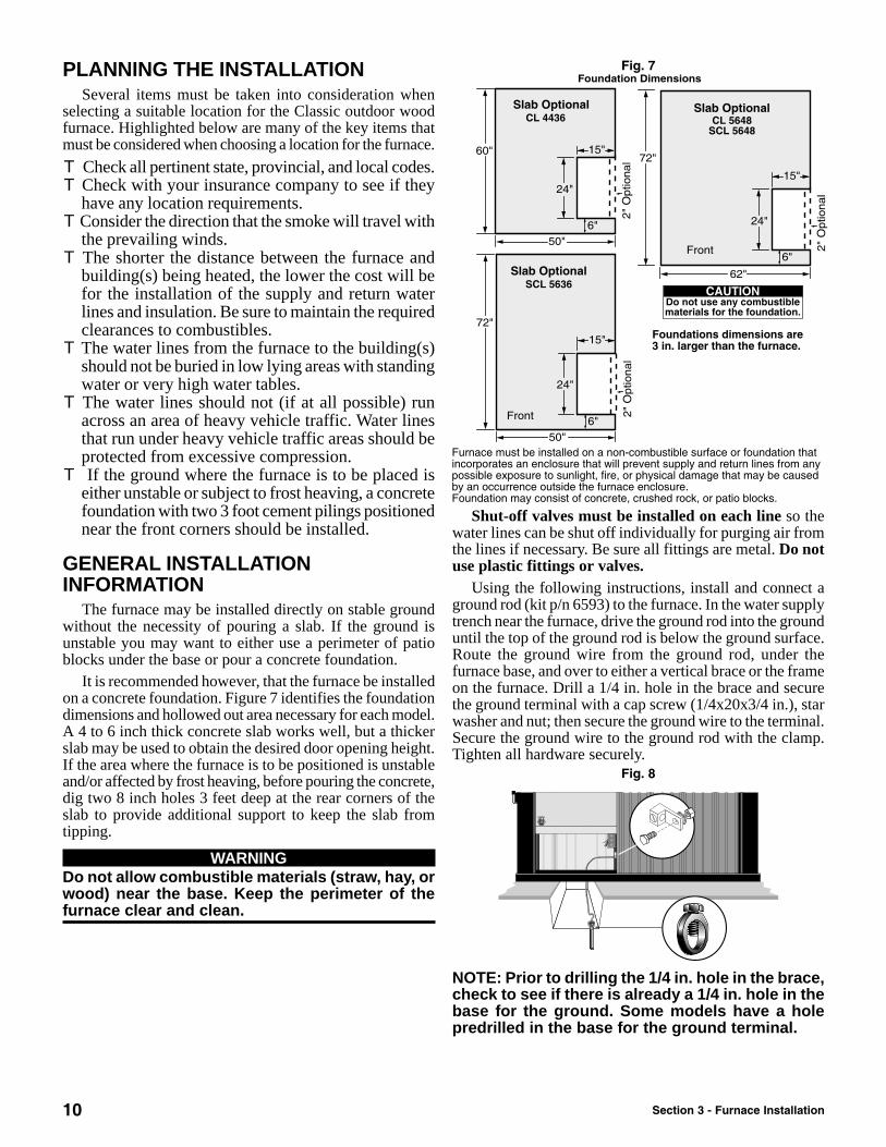
It is recommended however, that the furnace be installedon a concrete foundation. Figure 7 identifies the foundationdimensions and hollowed out area necessary for each model.A 4 to 6 inch thick concrete slab works well, but a thickerslab may be used to obtain the desired door opening height.If the area where the furnace is to be positioned is unstableand/or affected by frost heaving, before pouring the concrete,dig two 8 inch holes 3 feet deep at the rear corners of theslab to provide additional support to keep the slab fromtipping.
WARNINGDo not allow combustible materials (straw, hay, orwood) near the base. Keep the perimeter of thefurnace clear and clean.
Fig. 7
Shut-off valves must be installed on each line so thewater lines can be shut off individually for purging air fromthe lines if necessary. Be sure all fittings are metal. Do notuse plastic fittings or valves.
Using the following instructions, install and connect aground rod (kit p/n 6593) to the furnace. In the water supplytrench near the furnace, drive the ground rod into the grounduntil the top of the ground rod is below the ground surface.Route the ground wire from the ground rod, under thefurnace base, and over to either a vertical brace or the frameon the furnace. Drill a 1/4 in. hole in the brace and securethe ground terminal with a cap screw (1/4x20x3/4 in.), starwasher and nut; then secure the ground wire to the terminal.Secure the ground wire to the ground rod with the clamp.Tighten all hardware securely.
Fig. 8
NOTE: Prior to drilling the 1/4 in. hole in the brace,check to see if there is already a 1/4 in. hole in thebase for the ground. Some models have a holepredrilled in the base for the ground terminal.
Section 3 - Furnace Installation
11
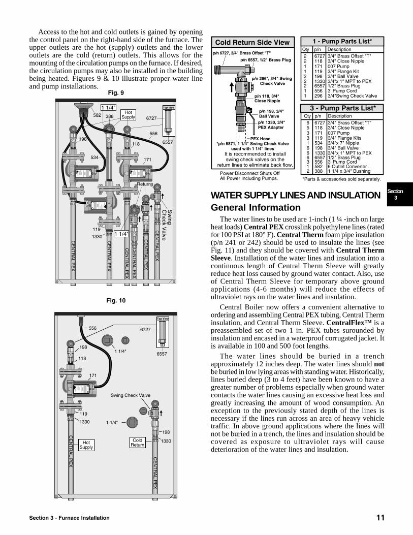
Access to the hot and cold outlets is gained by openingthe control panel on the right-hand side of the furnace. Theupper outlets are the hot (supply) outlets and the loweroutlets are the cold (return) outlets. This allows for themounting of the circulation pumps on the furnace. If desired,the circulation pumps may also be installed in the buildingbeing heated. Figures 9 & 10 illustrate proper water lineand pump installations.
Fig. 9
Fig. 10
WATER SUPPLY LINES AND INSULATIONGeneral Information
The water lines to be used are 1-inch (1 ¼ -inch on largeheat loads) Central PEX crosslink polyethylene lines (ratedfor 100 PSI at 180° F). Central Therm foam pipe insulation(p/n 241 or 242) should be used to insulate the lines (seeFig. 11) and they should be covered with Central ThermSleeve. Installation of the water lines and insulation into acontinuous length of Central Therm Sleeve will greatlyreduce heat loss caused by ground water contact. Also, useof Central Therm Sleeve for temporary above groundapplications (4-6 months) will reduce the effects ofultraviolet rays on the water lines and insulation.
Central Boiler now offers a convenient alternative toordering and assembling Central PEX tubing, Central Therminsulation, and Central Therm Sleeve. CentralFlex™ is apreassembled set of two 1 in. PEX tubes surounded byinsulation and encased in a waterproof corrugated jacket. Itis available in 100 and 500 foot lengths.
The water lines should be buried in a trenchapproximately 12 inches deep. The water lines should notbe buried in low lying areas with standing water. Historically,lines buried deep (3 to 4 feet) have been known to have agreater number of problems especially when ground watercontacts the water lines causing an excessive heat loss andgreatly increasing the amount of wood consumption. Anexception to the previously stated depth of the lines isnecessary if the lines run across an area of heavy vehicletraffic. In above ground applications where the lines willnot be buried in a trench, the lines and insulation should becovered as exposure to ultraviolet rays will causedeterioration of the water lines and insulation.
Section 3 - Furnace Installation
Section3

12
Fig. 11 Do not use a drain tile pipe, bubble wrap, or PVC pipefor water lines unless these pipes can be installed in a mannerthat allows the drainage of any water that could possiblyenter. If the water supply and return lines are not insulatedproperly, there can be excessive heat loss. This heat losscan greatly increase the wood consumption.
For a single building water to air heat exchanger system,the direction of water flow is to be as follows: from hotoutlet on the outdoor furnace to the bottom of the domesticwater heater exchanger, to the lower fitting of the heatexchanger on the existing furnace, and returned to the coldreturn of the outdoor furnace.NOTE: The direction of water flow is very importantfor the proper operation of the furnace.
The circulation pump(s) must be installed in the hotsupply line(s) with the arrow on each pump pointed awayfrom the furnace. In order to avoid circulation problems, donot install the pump(s) in the return line(s).
Fig. 12
Section 3 - Furnace Installation

13
If not mounted on the furnace, the circulation pump(s)need to be mounted 4 to 5 feet lower than the top waterlevel in the furnace (see Fig. 13 & 14). It is recommendedto mount the pump(s) at the furnace especially if the buildingbeing heated is higher than the furnace or if there is a largerise in the water lines between the furnace and the building(see Fig. 15 & 16). Hot water boils at a lower temperaturewhen pulled uphill (because it is at a lower pressure);therefore, hot water must be pushed uphill to ensure propercirculation. Shut-off valves should be installed on both sidesof each pump so if it becomes necessary to repair or replacethe pump, the water can be shut off on both sides of thepump. A screen or filter with a sediment chamber may beinstalled in the line to remove foreign particles which mightbe present in the water. The following guidelines must beadhered to when installing the circulation pump(s).A. The pump motor must be installed in a horizontal
position.B. The junction box must be located above the pump
motor.C. Do not run the circulation pump until the system has
been tested for leaks and filled with water.
NOTE: Be sure to follow the pump installationinstructions that are supplied with the pump if theydiffer from the information contained in thismanual.
Fig. 13
When the pump is located inside the building to beheated, a minimum of 4 feet between the water level in theoutdoor furnace and the highest point of the water linebetween the furnace and the building must be maintained.NOTE: The circulation pump(s) must be installedin the hot supply line(s).
Fig. 14
Fig. 15
Fig. 16
Manual air bleeders may be installed in the high pointsof the water lines where air may get trapped and causecirculation problems. Water can be pumped to levels higherthan the furnace as long as the pump is pushing the water tothe higher level and providing there are no air leaks in thesystem (see Fig. 17).
Fig. 17
Section 3 - Furnace Installation
Section3

14
InstallingNOTE: If installing CentralFlex™, the tubing,insulation, and sleeve assembly instructions in thissection may be ignored.
Prior to installing the water lines in the insulation,mark both ends of the hot line so that the hot water linecan be identified for correct installation. The hot fittingon the furnace takes the water from near the top of the waterjacket and the return is lower on the water jacket. It is veryimportant to keep the water lines properly identified.
When installing the water lines, an installation allowancefor expansion and contraction of the lines must be made. Ifthe water lines are mounted solid to the furnace or insidethe building, the lines may kink or the fittings may be pulledapart causing an immediate water loss from the furnace.Central PEX water lines can have an expansion/contractionrate up to 0.95 in./100ft/10°F.
A 14-2 underground rated wire (2 wires plus ground)may be buried in the same trench to supply the furnace withelectricity. A larger wire diameter may be needed if the runis over 200 feet. When installing the electrical supply forthe furnace, it is recommended that the incoming fuse orcircuit breaker not exceed 15 amps. The furnace must beelectrically bonded to ground in accordance with therequirements of the authority having jurisdiction or, inabsence of such requirements, with the National ElectricalCode, ANSI/NFPA 70 and/or the Canadian Electrical CodePart 1, CSA C22.1 Electrical Code.NOTE: If unavoidable that the trench is to be runthrough an area of ponding water, the installermust make certain that water will not enter theinstallation enclosure. One option is to encase thewater lines, insulation, and sleeve in corrugatedflexible tubing and digging the trench with a slightslope to one direction or the other (preferably awayfrom the building) to allow drainage of any waterthat may enter the tube.1. Remove the siding panel and base trim below the
control panel. Dig a trench 12 inches deep betweenthe furnace and building(s) to be heated; then makean entrance for the lines into the building(s).
WARNINGBefore trenching, be sure to call for locator service.
2. Mark both ends of the hot water line; then install bothwater lines in the Central Therm foam pipe insulationusing the following procedure:
A. Using a large mitre box and a fine tooth saw, trimboth ends of each insulation section.
NOTE: The insulation sections must be trimmedsquare so they can be glued together during theinstallation process.
B. To make inserting the water lines easier in theinsulation, insert a rod into the end of each waterline; then securely tape the rods to the water lines.
NOTE: The rods should be long enough to beinserted into the insulation section and grabbedfrom the other end.
C. For each insulation section, slide the rods into theinsulation section; then pull the water line throughthe insulation. Continue until the water lines havebeen threaded into all insulation sections.
Fig. 18
D. Using contact cement, glue the ends of theinsulation sections together; then using tile tape,tape the perimeter of each seam.
E. Measure the length of Central Therm Sleevenecessary to run the entire length of the installation,add two additional feet (minimum), and cut. Slidethe sleeve over the insulation; then wrap each endand secure with duct tape. Waterproof each endwith silicone or other waterproofing agent.
3. Lay the supply lines into the trench and feed one endinto the building. Apply sealant around the lineswhere they enter the building. Do not backfill thetrench until the water lines have been tested to ensurethere are no leaks.
NOTE: All holes made in basement or buildingwalls are to be completely sealed to prevent waterfrom entering the building.4. Connect the water lines to the furnace and building
allowing for expansion and contraction of the linesat each end.
5. Install the base trim; then using sand or fine dirt, backfill the perimeter of the water line enclosure to thetop, inner edge of the base. Install the siding panel.
Fig. 18a
Section 3 - Furnace Installation

15
Wiring The Circulation PumpsUpon completion of the water lines and circulation
pump(s) installation, the circulation pump(s) must beproperly wired using the following procedure. Perform theprocedure on each pump and power cord assembly. Powercords must be UL listed and rated for 221° F.
WARNINGDo not attempt service inside the electrical controlpanel without first disconnecting the electricalpower at the main power source.NOTE: Any electrical installation should be doneby a certified electrician in accordance with allapplicable codes.1. Remove the screw securing the capacitor box cover;
then remove the cover.2. Slide the metal strain relief onto the end of the cord
assembly; then insert the end of the cord assemblyinto the capacitor box. Secure the strain relief to thebox and cord assembly. Tighten securely.
3. Slide the green wire beneath the green screw; tightensecurely. Join the white wires and secure with a wirenut. Join the yellow and black wires and secure witha wire nut.
4. Carefully position all wires within the capacitor boxand install the cover. Secure with the screw.
5. Plug the cord into the receptacle. Route or tie the cordso it does not contact any hot areas of the furnace orwater lines.
6. Insulate the areas around the water lines and pump(s);then install and secure the cover.
Fig. 19
NOTE: If installing three pumps, use a UL approvedsplitter on the receptacle outlet.
CAUTIONMaximum load of the outlet is 10A, 120VAC, and 60Hz.
WATER HEATER INSTALLATIONInstalling a domestic hot water heat exchanger in the
building that is being heated is an inexpensive way to captureadditional savings from installing the outdoor wood furnace.The hot water line from the furnace should be plumbed firstto the water heater heat exchanger and then to the balanceof the heating system.
When necessary in certain applications, a 3-way zonevalve should be installed so that during the non-heatingseason, the water heater may be operated without operatingthe entire heating system. A tempering valve (or anti-scaldvalve) is to be installed in the hot water outlet from thewater heater. Install a tee in a fitting on the top of the waterheater (see Fig. 20) for the hot water heat exchanger.NOTE: If the water heater has been in service andcontains an anode rod, flush the water heater priorto installing the hot water heat exchanger asexisting anode rod residue may tend to plug theheat exchanger.
Fig. 20
WARNINGDO NOT disable or remove any safety reliefs orcontrols. Turn off the power to the water heaterbefore starting the installation process.
Section 3 - Furnace Installation
Section3

16
EXISTING FORCED AIRINSTALLATION
When the Classic furnace is installed in conjunction withan existing forced air system, a water-to-air heat exchangeris to be mounted in the plenum or duct work of the existingfurnace. Heated water from the outdoor wood furnacecontinuously flows through the water to air heat exchanger.When the thermostat senses the need for heat, the fan onthe existing heating system forces air through this heatexchanger transferring heat throughout the existingductwork.
If an air conditioning coil is located in the plenum, theheat exchanger should be mounted between the fan and theair conditioning coil so the heat exchanger will not freezeup when the air conditioner is being used. The heatexchanger should not be installed in the cold-air return ofthe existing forced air furnace because the possibility existsthat components of the existing furnace could overheat andcause the existing furnace to operate other than intended.The heat exchanger may be mounted either horizontally orvertically with the outlets on the side (see Fig. 21). In allapplications, the heat exchanger must be mounted level fromfront to back, with the outlets on the side. If the outlets arepositioned upward or if the exchanger is not level, an airlock can restrict the water circulation and reduce the amountof heat transfer. The lower fitting is the inlet from theoutdoor wood furnace and the top fitting is the outlet forreturn to the outdoor wood furnace. If the plenum is largerthan the heat exchanger, it should be mounted in the centerwithout gaps on the sides that would allow air to flowaround the heat exchanger. All air must be directed throughthe face of the exchanger. Be sure to consider the airflowthrough the ductwork so heat isn’t blocked off to parts ofthe building.
Fig. 21
Adding a heat exchanger coil in the hot air plenum orductwork of the existing furnace may decrease the air flow inthe system. The existing heating (gas or electric) system shouldbe operated before adding the heat exchanger. The airtemperature rise should be measured with the system runningfor an adequate amount of time to get a stabilized temperaturereading. The heat exchanger can then be installed in the system.The existing heating system should be operated again and theair flow should be adjusted to maintain the same temperaturereading. The air flow may have to be increased to accomplishthis. On a belt-drive system, the blower pulley and/or motorpulley may be changed but the electrical current flowingthrough the motor shall not be changed to exceed the nameplaterating. A blower motor of larger power may be used. In mostcases on a direct-drive system, the blower motor will not needto be replaced; however, the speed of the blower motor mayhave to be increased.
CAUTIONWhen installing the heat exchanger, be sure noneof the existing system safety controls are disabled.NOTE: Any electrical installation should be doneby a certified electrician in accordance with allapplicable codes.
A snap disc temperature control should be installed onthe heat exchanger manifold to provide an interlock for theair conditioner. This prevents the air conditioner fromoperating when the water temperature is higher than 140° F.
There are several methods to install thermostatic controlsfor this type of installation. If the existing heating system iscontrolled by a 4 wire, 24 volt thermostat, the simplestmethod is to add a second 24 volt thermostat. The secondarythermostat will control the room temperature at which thefan on the existing heating system will activate with heatbeing drawn from the Classic furnace and should be set tothe desired room temperature. The existing heating systemthermostat should be set to a temperature 4-5° lower thanthe secondary thermostat and controls the temperature atwhich the existing heating system will activate as a backupto the outdoor wood furnace. Connect the thermostatsaccording to the following wiring diagram (see Fig. 22).
Fig. 22
Section 3 - Furnace Installation

17
An alternative method is to install a line voltagethermostat to control the blower on the existing furnace. Inthis installation, a 120-volt line is run from the thermostatto the furnace where one wire is connected to the hot (linefeed) and the other wire to the furnace blower wire. A lowwater temperature switch may be installed to shut off theblower if the temperature of the water is too low. This switchis connected in series to the wire coming from the thermostatpreviously mentioned. This switch must be installed so thatit does not affect the existing system thermostat.
NOTE: If a low water temperature switch is notinstalled, the fan will run continuously even whenthe outdoor wood furnace is out of wood. Notinstalling the switch is acceptable if it is desiredto keep the water in the furnace the sametemperature as the air temperature in the houseto prevent the water in the furnace from freezing.
Fig. 23
Section 3 - Furnace Installation
Section3

18
Fig. 24
Section 3 - Furnace Installation

19
HEATING MULTIPLE ZONES OR BUILDINGSA single pump and manifold may be used to heat more than one zone or building as long as the return water can be
maintained above 150°F. If the return water temperature can not be maintained above this level, then a separate pumpshould be used for each building and a one way swing check valve should be installed on the outlet side of each pump.Side panel models offer three sets of outlets (for up to three zones or buildings without the need for manifolds) for themounting of up to three pumps on the furnace.
Fig. 25
Central Boiler 2004
Section 3 - Furnace Installation
Section3

20
HYDRONIC INSTALLATIONSIf a water-to-water heat exchanger is to be used with an
existing heating system, the existing heating system mustbe able to adequately heat the building with a watertemperature of approximately 165° F. Some existing fin tubebaseboard hot water heating systems are designed to operatewith water temperatures up to 220° F or higher. If the existinghot water heating system has had trouble maintaining thetemperatures in the home at any time during cold weatherbefore installing the outdoor wood furnace, then the systemis not adequate to work properly. Evaluate the existing hotwater system before starting the installation. If the existingheating system is marginal or designed to operate with watertemperatures above 165° F, there are alternative installationprocedures that will make the system work very well withthe Classic outdoor wood furnace. These include:1. More fin tube water baseboard heaters can be added.2. A water to air heat exchanger with a thermostatic
controlled fan can be installed in the lower part ofthe building being heated. This can increase theamount of heat added to the building to maintain aconstant temperature. This heat exchanger can beadded in the return line of the outdoor system afterthe water-to-water heat exchanger.
3. An additional radiant heating circuit can be added toheat areas that require additional heat.
Vented System InstallationNOTE: Any changes in the existing boiler shouldbe done by a certified plumber in accordance withapplicable codes.
When installing the outdoor wood furnace in conjunctionwith an existing hot water system, it can be connecteddirectly into the existing system changing it to anatmospheric vented system. The hot supply line from thefurnace can be connected into the top of the existing boilerand returned to the outdoor wood furnace from the bottomof the boiler (see Fig. 26). Use one pump to continuouslycirculate the water from the outdoor wood furnace throughthe existing boiler and back to the outdoor wood furnace.
CAUTIONThe outdoor wood furnace must NEVER bepressurized. The vent cap must always be loose.Do not extend the vent pipe. The furnace will bedamaged if it is pressurized.
When the existing system is connected to the outdoorsystem as illustrated in Fig. 26, the circulating pump(s) inthe existing system must be located in the hot supply line(s),not in the return line(s).
Fig. 26
Section 3 - Furnace Installation

21
It is very important to purge all air and eliminate all airand water leaks (valve packings, bleeders, etc.) from theexisting system. After filling the outdoor furnace (asdescribed in the Initial Start-Up Procedures section) andexisting system with water, purge the air from the indoorsystem by closing the valves on the outdoor furnace thenpressurize the indoor system with water from the domesticwater line.
Bleed air from the pressurized indoor system then operatethe circulating pump(s) on the indoor system. Perform thisprocedure twice. If any auto float vents are used in theexisting system, they must be capped off tight after the airbleeding is completed. This eliminates the possibility ofallowing air to enter after the system is depressurized. Whenair bleeding is finished, close the valve on the water lineused to pressurize the indoor system. If any air is allowedin the system, the system will not operate properly. Openvalves on the outdoor furnace, turn on the pump and proceedto fire the furnace.
Pressurized Water System InstallationsWATER TO WATER HEAT TRANSFER SYSTEM
If it is preferred to keep the existing system pressurized, awater-to-water heat exchanger may be used (see Fig. 27). Thisis to be installed in the return line of the existing system. Thewater from the existing system passes through the heatexchanger when the thermostat calls for heat. The water fromthe outdoor furnace circulates through the other part of theheat exchanger continuously. The water temperature at whichthe existing burner starts up may need to be lowered to a setting(approximately 120° F) that prevents the existing boiler burnerfrom cycling on when the outdoor wood furnace is heatingthe home.
Water to water heat exchangers will produce transfertemperatures approximately 20º F less than the outdoor woodfurnace water temperature; therefore if the controller is set at185° F, it will produce approximately 165° F of watertemperature transfer. Each system will vary in water temperaturetransfer depending upon the heat loss of the existing heatingsystem. The controller may be adjusted to allow the outdoorwood furnace to reach water temperatures up to 195º F.
Fig. 27
Section 3 - Furnace Installation
Section3

22
WATER TO WATER HEAT TRANSFER SYSTEMUSING A WRAPAROUND HEAT EXCHANGER
Another option for installing the water-to-water heatexchanger for increased heat transfer is illustrated in Fig.26. This wraparound installation allows circulationcontinuously through the heat exchanger, maintaining themaximum exchanger temperature in the existing boiler. Notethe water flows in opposite directions.
With this type of installation, the exchange temperaturemay be more than 165° F and may eliminate the need foradditional baseboard heaters or other added heat exchangeras illustrated.
When installing water-to-water heat exchangers, be sureto flush any rust particles or sediments out of existing boiler.A 009 Taco pump must be used for the outdoor system andAnti-Sludge Conditioner (p/n 166) also must be added inthe outdoor wood furnace.
Fig. 28
Section 3 - Furnace Installation

23
Direct Circulation Baseboard InstallationBaseboard heaters, as either the main source of heat or as supplements to forced air or boiler applications are easily
plumbed into the water lines from the outdoor wood furnace. The following illustrations detail the proper plumbing methods.Fig. 29
Fig. 30
Section 3 - Furnace Installation
Section3

24
Radiant Floor System InstallationsInstalling radiant floor (ceiling) heating is a very viable
heating option when either remodeling or building new.Radiant floor heat can also be adding to an existing homeeasily if the floor joists are exposed (as in an unfinishedbasement). The tubing may be installed in a wide variety ofconfigurations and locations including but not limited tothe following: in or under a concrete slab, within the subfloorsystem (gypcrete), within the floor and ceiling joist system,or within the walls.
When installing tubing between floor joists (16 in. oncenter) run two ½ in. tubes between each joist. Insulatebelow tubing to prevent excessive heat in the lower level.
Fig. 31
Section 3 - Furnace Installation
Proper insulation is key to effective radiant heating andcontrolling large heat demands. Heat from this type ofsystem radiates nearly equally in all directions; therefore asan example, if tubing is installed below a slab, the groundbelow the slab must be dry and well insulated. If not properlyinsulated, nearly 50% of the heat will be wasted warmingup the ground below the slab.
Areas with high water tables need to be prepared properlyto avoid contact between the ground water and tubing.
The following illustrations are examples of radiantheating systems using ½ in. tubing in the loops. The spacingof each circuit should be 12 in. between tubes. The watercirculates in opposite directions to provide an evendistribution of heat. The mixing valve regulates thetemperature of the water circulating through the loops bymixing return water with the supply water (140º F or less ispreferred). In areas where high heat loss is expected, loopspacing may be reduced to 10 in. or less. If additionalinformation is desired, contact either your dealer or CentralBoiler.

25
Fig. 32
Fig. 33
Section 3 - Furnace Installation
Section3

26
Fig. 34
High Volume Water HeatingFig. 35
Section 3 - Furnace Installation

27
Pool And/Or Hot Tub HeatingFig. 36
Valves should be installed so the heat exchanger can beisolated when shock treating or adding chemicals. Highchemical concentrations from improper feeding of chemicalscan cause rapid corrosion to the heat exchanger. Bypassingthe heat exchanger is recommended prior to the stabilizationof pH between 7.2 and 7.8.
CAUTIONDo not install a swimming pool heat exchangerinside a home or building below the level of thepool as a damaged heat exchanger may result inextensive flooding and draining of the pool.
WARNINGDo not use automotive or ethylene glycol antifreezein the outdoor wood furnace connected to aswimming pool heat exchanger as a damaged heatexchanger may cause severe personal injury,death, or substantial property damage.
Section 3 - Furnace Installation
Section3
28
FINALIZING THE INSTALLATIONBefore firing the furnace for the first time,
perform the following important items:A. Check for leaks. Pressure test the entire plumbing
system. Apply 30 lb of pressure for thirty minutesand closely monitor for any pressure loss. Inspect allfittings and hose ends for any signs of leakage; repairas necessary. A very slow leak at a hose clamp maypossibly be stopped by tightening the clamp after thesystem has warmed up as the poly becomes morepliable when it is warm. It also may be necessary toinstall a second hose clamp with the screw positionedon the opposite side of the hose. Release the pressureupon completion of the test.
NOTE: PEX lines should never be pressurizedwhen the heating system is being operated.B. Cover Water Lines. Backfill the trench dug for the
installation of the water lines. If the water lines areto be run on top of the ground, cover the lines as theywill deteriorate with exposure to UV rays.
C. Remove the strapping securing the vent cap. Thevent cap must fit loosely over the furnace vent.
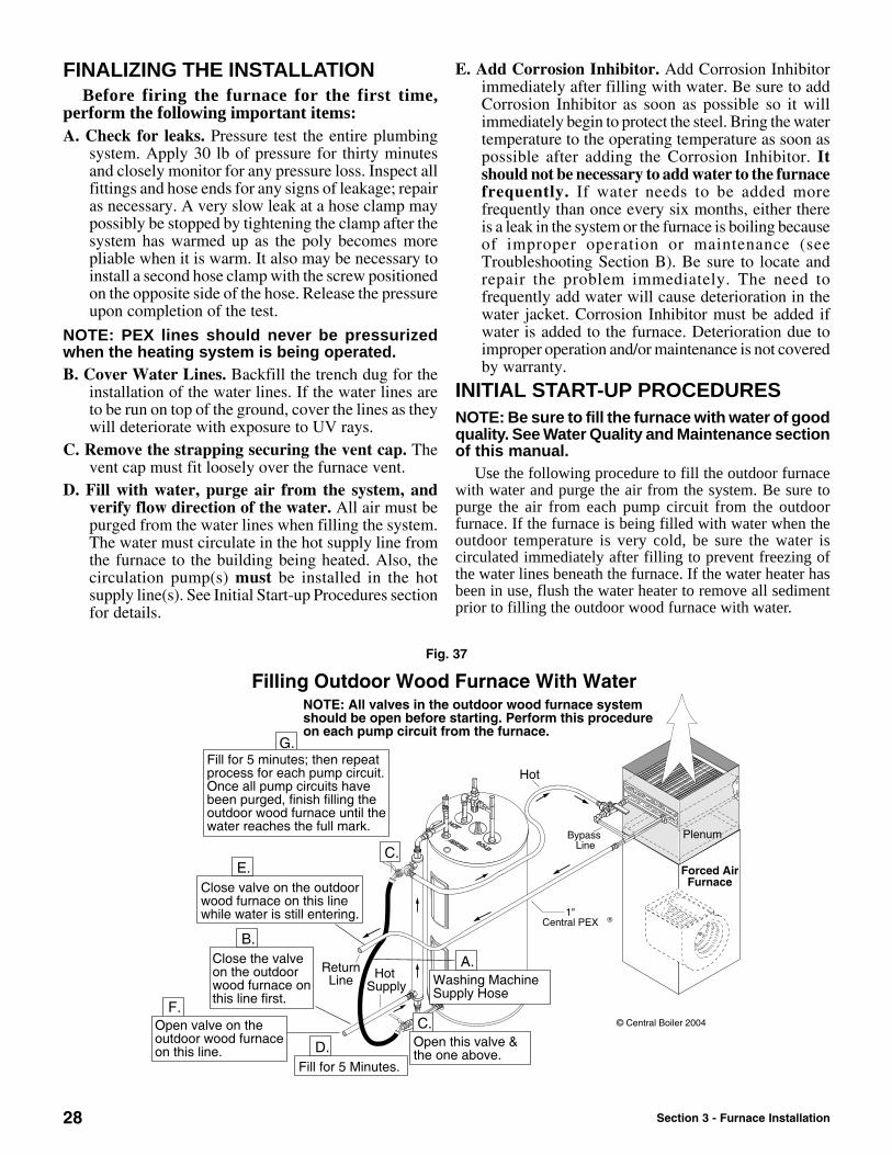
D. Fill with water, purge air from the system, andverify flow direction of the water. All air must bepurged from the water lines when filling the system.The water must circulate in the hot supply line fromthe furnace to the building being heated. Also, thecirculation pump(s) must be installed in the hotsupply line(s). See Initial Start-up Procedures sectionfor details.
E. Add Corrosion Inhibitor. Add Corrosion Inhibitorimmediately after filling with water. Be sure to addCorrosion Inhibitor as soon as possible so it willimmediately begin to protect the steel. Bring the watertemperature to the operating temperature as soon aspossible after adding the Corrosion Inhibitor. Itshould not be necessary to add water to the furnacefrequently. If water needs to be added morefrequently than once every six months, either thereis a leak in the system or the furnace is boiling becauseof improper operation or maintenance (seeTroubleshooting Section B). Be sure to locate andrepair the problem immediately. The need tofrequently add water will cause deterioration in thewater jacket. Corrosion Inhibitor must be added ifwater is added to the furnace. Deterioration due toimproper operation and/or maintenance is not coveredby warranty.
INITIAL START-UP PROCEDURESNOTE: Be sure to fill the furnace with water of goodquality. See Water Quality and Maintenance sectionof this manual.
Use the following procedure to fill the outdoor furnacewith water and purge the air from the system. Be sure topurge the air from each pump circuit from the outdoorfurnace. If the furnace is being filled with water when theoutdoor temperature is very cold, be sure the water iscirculated immediately after filling to prevent freezing ofthe water lines beneath the furnace. If the water heater hasbeen in use, flush the water heater to remove all sedimentprior to filling the outdoor wood furnace with water.
Fig. 37
Section 3 - Furnace Installation

29
All valves in the outdoor wood furnace system shouldbe opened before starting this procedure.1. Connect a washing machine supply hose (a garden hose
with two female ends) to the pressurized domestic waterline. Run water into pail or other container until clear;then connect to the outdoor system.
2. Close the valve on the hot (supply) line of the outdoorwood furnace.
3. Open the two valves that allow the pressurized domesticwater to fill into the system (water will start enteringthe furnace through the return line). Confirm that thewater lines are connected correctly by feeling thewater lines as indicated by the arrows. They shouldimmediately feel cold to the touch. If they don’timmediately feel cold but the other ones do, stopfilling the furnace as the water lines are reversed.Continue filling the furnace after switching the returnand supply water lines.
4. Let the outdoor wood furnace fill for about five minutes.5. Close the valve on the return line of the outdoor wood
furnace (both valves are now closed) while the wateris still entering the outdoor wood furnace.
6. Open the valve on the hot (supply) line of the outdoorwood furnace.
Fig. 38
7. Fill for 5 minutes; then if more than one pump circuitis present, close the valves and repeat the process foreach pump circuit. Once all pump circuits have beenbackfilled with water, finish filling the outdoor woodfurnace until the water level reaches the FULL mark.
8. Close the two filling valves.9. Open all valves on the outdoor wood furnace. This
will allow the water to circulate throughout the systemwhen the pump(s) are operating.
NOTE: The outdoor wood furnace can also be filledthrough the vent in the top of the furnace and theair can be bled out with bleeders.
CAUTIONBe sure the outdoor wood furnace is filled withwater before firing. Never fire the furnace with thewater level below the FULL mark.Never drain water from the furnace with live coalsor fire in the furnace. If the furnace ever boils hard,be sure to check the water level and restore to fullif necessary.If water is added, the proper level of CorrosionInhibitor (p/n 165) must be maintained.
WARNINGNever leave the door open or ajar whenunattended. The fire cannot be controlled by thedraft opening when the door is open.
10. Turn on the circulation pump(s); then fire up theoutdoor wood furnace. When the water reaches theoperating temperature, finish filling the furnace tothe full level on the sight gauge; then close the sight-gauge valve and disconnect the filling hose.
NOTE: When filling is completed, the sight-gaugevalve should be closed. The water willautomatically drain from the sight-gauge tube.Remember, this type of valve requires only ¼ turnopen and close.
CAUTIONDo not force the water level check valve in the openposition, as it may damage the valve and causethe valve to leak. This type of valve requires only¼ turn to open and close.
Section 3 - Furnace Installation
Section3

30
A. FURNACE DOES NOT HEAT (BUILDING IS LOSING
TEMPERATURE)
1. Circulation valve(s) closed - Be sure all valves in thesystem are open.
2. Out of wood - Check firebox to see if fire is out. Addwood as necessary. Use good quality wood as poorquality wood will have very short burn times.
3. Solenoid not operating properly - Disconnect powerto the furnace: then check fuse in control panel. Iffuse is blown, check damper door for obstructionsand free movement. Be sure damper door worksfreely; then replace the fuse. Check the solenoidplunger free length. With the damper door fullyclosed, the correct length is between 15/16 and 1 in.(see Fig. 40). Adjust if necessary, but do not exceed1 in. Be sure that the damper door (when activatedby the solenoid) does not contact the louvered cover.Lubricate or adjust as necessary.
4. Circuit breaker off - Check the circuit breaker thatsupplies power to the furnace.
5. Furnace exhaust obstructed - Check furnace exhaustfor obstructions by observing the amount of smokecoming out of chimney with the firebox door slightlyajar. If smoke seems very restricted, remove thefirewood and hot coals and check chimney (top andbottom) and behind the baffle for obstructions.
6. Circulation pump not operating/installedbackwards - Check to see if circulation pump isoperating and pump flow direction is correct. If not,shut off power to pump. If the flow is not the correctdirection, disconnect pump from water line andreverse pump mounting to correct flow direction. Alsoif not mounted on the furnace, check for proper pumpmounting location (see Fig. 13-16). Be sure the poweris disconnected before working on the pump. Closevalves at the pump. Take the pump apart and try toturn pump shaft. If shaft is stuck, replace pumpcartridge (or pump if necessary). Replace only thecartridge whenever possible. Follow instructionssupplied with the pump.
7. Air in system - Check for air in the water lines or heatexchanger. If you hear a gurgling sound in the heatexchanger, air is present in the system. Either shutoff the pump and wait 15 seconds and try again orforce air from lines as described earlier in filling thefurnace with water (pages 28-29).
8. Water lines installed incorrectly - Make sure the hotsupply water line is connected to the correct fittingon the furnace and heat exchanger (see Fig. 9 & 10).
9. Water lines insulated poorly - Heat loss inunderground lines (evidenced by an unusually highamount of snow melting above lines when the groundtemperature is 20º F or colder) due to improperinstallation (see Water Supply Lines And Insulationsection).
10. Water lines uninsulated - Losing heat fromuninsulated water lines in areas that are not intendedto be heated (unheated crawl spaces, under mobilehomes, etc.). Correct the situation by insulating thelines.
11. Excessive building heat loss - Poorly insulated oruninsulated building and/or buildings withuninsulated or poorly insulated ceilings can causeexcessive wood consumption and or heatingproblems.
B. FURNACE IS OVERHEATING OR BOILING.
NOTE: If furnace boils do not be alarmed, butidentify the cause and correct immediately; thefurnace will not be damaged by boiling unlessrepeated boiling reduces the water level below thesafe level. If water boils, restore water level to fulland add Corrosion Inhibitor. If water is addedfrequently it will cause deterioration in the waterjacket which will reduce the life of the furnace.1. Air entering through the door - Make sure the door
is properly latched. Check the condition of the doorrope. If it is not sealing properly (as indicated by auniform indentation in the rope), replace the rope. Ifdoor does not close tightly, adjust using theappropriate procedure.
Loosen the adjustment nut (two nuts on the dualCam Loc® style door) and slide the lock assemblyin slightly toward the furnace; then tighten securely(see Fig. 39). On the dual Cam Loc doors, makesure to adjust both the top and bottom for equalpressure when latched.
Fig. 39
2. Air entering through the damper - Check to be surethe damper is operating correctly as explained insection A.3. Be sure the damper closes all the wayand that no obstructions are present. If the solenoidis sticking, lubricate with silicone spray or a lightpetroleum distillate (WD-40 or equivalent). Checklinkage for binding.
SECTION 4 - TROUBLESHOOTING
Section 4 - Troubleshooting

31
3. Temperature controller set incorrectly - Thetemperature controller should not be set above 195°F.
4. Circulation pump not running - The pump shouldrun continuously to keep water temperature uniformin furnace while in use.
NOTE: If there is an overheating problem inextremely warm weather, the furnace can be filledwith a smaller load of wood.C. SOLENOID DOES NOT OPERATE.
1. Fuse blown - Check the fuse. Check damper andsolenoid area for obstructions or damage. Be surethe damper door operates properly; then replace thefuse.
2. Solenoid not operating properly - Solenoid may bedamaged. If so, be sure to check the linkage for freemovement and for creosote buildup between damperdoor and draft opening. Replace the solenoid if burnedout or stuck in the open position. The solenoid is anowner serviceable item (see instructions forreplacement in Maintenance section of this manual).
D. FREQUENT PUMP TROUBLE OR POOR WATER
CIRCULATION.
1. Pump mounted incorrectly - Check to be sure thepump is mounted either on the furnace or a minimumof 4 feet lower than the top water level in the furnaceor the highest point of the supply lines between thefurnace and the pump (see Fig. 13-16).
2. Water will not circulate - If the system has beendrained and there is a problem getting the water tocirculate, force water through all lines with waterpressure from pressurized domestic water system,closing one valve at a time on the furnace to forcewater through each line. See Initial Start UpProcedures section.
E. ERRATIC TEMPERATURE READING ON GAUGE.
1. Return water too cold - Water circulation may be tooslow. The return water should be no more than 20°-25° F less than hot supply water. Returning waterthat is too cold to the furnace may cause erratictemperature readings. Check for partial air lock orinstall larger pump.
F. BURNING AN EXCESSIVE AMOUNT OF WOOD.
1. Excessive heat loss - See 9-11 of Furnace Does NotHeat section.
2. Air entering through door - See 1 of Furnace IsOverheating Or Boiling section.
3. Excessive draft - If a very tall extension is added tothe chimney, the increased draw through the draftmay cause excessive wood consumption. Decreasingthe draft opening may increase efficiency and reducewood consumption.
4. Water line heat loss - If water lines are buried in wet,low-lying areas, there may be a large heat loss whichwould greatly increase the wood consumption.
5. High volume water heating - High volume waterheating (e.g., car wash, swimming pool, etc.) willrequire high wood consumption.
6. High heat demand - Radiant floor heating a concreteslab that is either poorly insulated or is exposed towater or cold outside temperatures will requireincreased wood consumption. Bringing a concreteslab up to temperature the first time will take aconsiderable amount of time and wood, but once it iswarm, the wood consumption will be reduced if theconcrete and the building are insulated properly.
Section 4 - Troubleshooting
Section4

32
NOTE: If any of these items are under warranty,remember that the warranty covers only the costof the replacement part. Labor is not covered.CIRCULATION PUMP
Taco® circulation pumps can be easily replaced orrepaired. The pumps have a replaceable cartridge that canbe installed easily.1. Shut off (or disconnect) the electrical supply to pump.2. Shut off valves on both sides of pump.3. Remove the four screws securing the motor and
impeller assembly to the cast body of the pump; thenremove the motor from the pump.
4. Pull the replaceable cartridge from the assembly andinstall new cartridge.
5. Place motor assembly into position on the cast bodytaking care to properly position the gasket. Secure withfour new screws. Tighten securely.
6. Open both valves and check for leaks; then turn onelectrical supply.
NOTE: Instructions are provided with replacementcartridge. Be sure to follow manufacturer'srecommendations if they differ from theseinstructions.SOLENOID
Prior to replacing the solenoid, check the following items.1. Check to be sure there is incoming power to the furnace.2. Check inside the control panel to see if the fuse has
blown. If the fuse is blown, check the draft openingto be sure the linkage operates freely and that thereare no obstructions to the door; then replace the fuse
3. If solenoid still does not operate, turn the PowerDisconnect Switch to the off position.
WARNINGDo not attempt service on the solenoid without firstdisconnecting electrical power to the solenoid.4. Remove the screws securing the draft enclosure cover;
then remove the cover.
CAUTIONSolenoid may be hot.
5. Carefully disconnect the two wire leads connected tothe left side of the solenoid by gently pulling andmoving them from side to side.
6. Remove top cotter key of the linkage.7. While supporting the solenoid with your hand, remove
the top two solenoid mounting screws and loosen thebottom two.
8. Lift up on the solenoid until it clears the screw headsand remove.
9. Place the new solenoid into position and lightly securewith the screws. Adjust the solenoid up or down untilthe solenoid plunger free length is between 15/16 and1 in.; then tighten the screws securely. Connect thesolenoid to the linkage with the cotter pin. Slightlyspread the legs of the cotter pin.
10. Carefully attach wire leads onto the solenoid terminals(white wire connected to the upper terminal).
11. Install the cover and secure with the screws.12. Turn the Power Disconnect Switch to the ON position.
NOTE: If the solenoid rattles during operation, thealignment between the solenoid and the lift tab isincorrect. To align the solenoid and lift tab, loosenthe four solenoid mounting screws and move thesolenoid until the solenoid plunger aligns with thelift tab. Secure the solenoid; then make sure itoperates smoothly.
Fig. 40
TEMPERATURE CONTROLLER1. Remove all wood and live coals from the firebox.
CAUTIONRemove all wood and live coals from the furnace.Do not perform this procedure with any live coalsin the furnace.2. Disconnect the electrical power at the main power
source to the wood furnace; then open the controlpanel door. Remove the screws securing the innerdoor panel; then remove the panel.
WARNINGDo not attempt service inside the electrical controlpanel without first disconnecting the electricalpower at the main power source.3. Carefully label each of the wires connected to the
temperature controller according to the numberedconnections identified on the top of the controller.
4. Using a small screwdriver, loosen the screws securingeach of the wires; then pull the wires out of thecontroller.
SECTION 5 - OWNER SERVICEABLE ITEMS
Section 5 - Owner Serviceable Items

33
Fig. 41
5. Depress the tabs on the side of the controller mountingstrap; then slide the strap off the controller. Removethe controller from the control panel.
6. Place the new gasket onto the controller. Slide the newcontroller into position (making sure it is positionedupward) in the control panel; then secure with themounting strap.
7. Slide each of the labeled wires into their properpositions on the controller; then tighten each of thescrews securely.
8. Place the inner door panel into position on the doorand secure with the screws.
9. Close and secure the door. Connect power to thefurnace.
WATER TEMPERATURE SENSOR1. Remove all wood and live coals from the firebox.
CAUTIONRemove all wood and live coals from the outdoorwood furnace. Do not perform this procedure withany live coals in the furnace.2. Disconnect the electrical power at the main power source
to the outdoor wood furnace; then open the controlpanel door. Remove the screws securing the accessbox panel; then remove the panel.
WARNINGDo not attempt service inside the electrical controlpanel without first disconnecting the electricalpower at the main power source.
Fig. 42
Temperature Controller
Water Temperature Well
Sensor Wire
3. Remove (by pulling) the sensor wire from the well.4. Firmly press the sensor wire into the well.5. Place the access box panel into position and secure
with the screws.6. Close and secure the door. Connect power to the
furnace.
Section 5 - Owner Serviceable Items
Section5

34
Fig. 43
WIRING DIAGRAMSFig. 44
SECTION 6 - GENERAL INFORMATION
Section 6 - General Information

35Section 6 - General Information
PARTS LISTING, CL 4436Fig. 45
Section6

36
PARTS LISTING, CL 5636Fig. 46
Section 6 - General Information

37Section 6 - General Information
PARTS LISTING, CL 5648 & SCL 5648Fig. 47
Section6

38
FURNACE MEASUREMENTSFig. 48
Section 6 - General Information

39
INSPECTION RECORDDate Inspection Performed Date Inspection Performed
Section 6 - General Information
Section6

p/n 599 Printed in USA 0105
1 YEAR LIMITED WARRANTYCentral Boiler, Inc. (hereinafter referred to as Central Boiler) warrants the original owner of a Central Boiler
model CL 4436, CL 5648, SCL 5636, or SCL 5648 outdoor wood furnace to be free from defects in the workmanshipof all parts of the outdoor wood furnace manufactured by Central Boiler for a period of 1 year from date of manufacture.Central Boiler reserves the right to repair or replace any defective part(s), to replace the outdoor wood furnace witha comparable model, or to refund the purchase price. This warranty covers the cost of parts and labor to replace suchparts for the repair of the workmanship defect.
A 25 year Warranty is available if a completed Warranty/Registration is submittedto Central Boiler within five days of purchase.
If the outdoor wood furnace need be removed from it’s location for repair, the warranty excludes the cost ofshipping, labor for removal and installation, plumbing labor and/or parts, and replacement of water or water additives.Physical damage caused by misuse or abuse, unauthorized work, alterations to the furnace, and normal wear items(such as door gasket, exterior paint, and replaceable chimney parts) are not considered warrantable items. Componentssuch as aquastats, pumps, actuators, etc., that are used on the outdoor wood furnace or in the heating system, carrytheir own warranty provided by their manufacturer.
Central Boiler is not liable for any incidents or accidents, which can be prevented by the owner or that may occurfrom the operation of the outdoor wood furnace, or damage incurred due to heating system failure. The ownerassumes all responsibility for the care, maintenance, and safe operation of the furnace.
THIS WARRANTY IS IN LIEU OF ALL OTHER WARRANTIES, EXPRESS OR IMPLIED, INCLUDINGTHE WARRANTIES OF MERCHANTABILITY OR FITNESS FOR A PARTICULAR PURPOSE. ThisWarranty gives you specific legal rights, and you may also have other rights which vary from state to state. Somestates do not allow the exclusions or limitation of incidental or consequential damages, so certain limitations orexclusions under the warranty may not apply to you.