satellite laser ranging using pseudonoise code modulated laser diodes
TRANSCRIPT
Satellite laser ranging using pseudonoise code modulatedlaser diodes
David M. Norman and Chester S. Gardner
Techniques for satellite laser ranging have historically employed high-energy pulsed lasers as the opticaltransmitter. The output power currently available from laser diodes and laser diode arrays makes them aviable alternative to the pulsed laser for ranging applications. We examine the modulation of a laser diode bya pseudonoise code which produces a cw ranging signal with equivalent average power to that of current pulsedsystems. A maximum-likelihood receiver for estimating signal arrival time using ideal rectangular pulses isshown to be a correlation receiver. A Cramer-Rao bound on the range error is derived for a ranging systemwith Gaussian code pulses and a correlation receiver. Ranging performance is evaluated for a single cube-corner retroreflector and a tilted flat diffuse target. It is shown that range accuracy of the order of 1 cm is fea-sible.
I. Introduction
Laser ranging to satellites has been performed sincethe mid-1960s for applications such as precise orbitdetermination, estimating the earth's internal massdistribution, and measuring tectonic plate motion.'Current systems employ high-energy pulsed Nd:YAGlasers capable of generating pulses of the order of 1 Jwith durations of several hundred picoseconds. Re-cent advances in the performance of laser diode arraysmake them a viable alternative to the pulsed lasersource in ranging systems. Laser diode arrays arebeing developed today with average power outputs ofthe order of 1 W and with modulation rates of the orderof 1 GHz. By modulating a laser diode array with apseudonoise (PN) code, a ranging signal can be trans-mitted with the same effective average power as that ofthe pulsed system. A receiving system utilizing thestatistical properties of the PN code can then extractrange information from the target-reflected signal.
In a laser ranging system, estimation of the arrivaltime of the reflected energy from the target is theparameter of interest. For current pulsed laser sys-tems, a portion of the outgoing pulse is sent to therange receiver to start a time-interval counter. 1 Thetransmitted pulse propagates to the target where it is
The authors are with University of Illinois-Urbana, Departmentof Electrical & Computer Engineering, Urbana, Illinois 61801.
Received 7 March 1988.0003-6935/88/173650-06$02.00/0.© 1988 Optical Society of America.
reflected back to the receiver. The leading edge of thereceived signal waveform is detected and stops thetime-interval counter. The time measurement isstored and possibly averaged with several other mea-surements to determine the range estimate. Mode-locked Nd:YAG lasers produce output pulses of theorder of 200 ps in duration with pulse energies of -100mJ. A pulse rate of 5-10 pps is typical, so that theaverage transmitted power is 1 W. For these sys-tems, the range measurement accuracy is of the orderof \IVN, where a is the laser pulse width (rms) and Nisthe expected number of received signal photocountsduring the measurement interval.
The technique discussed in this paper is to estimatethe time of flight of a PN code modulated rangingsignal generated by a laser diode array. A portableaerosol lidar system using this modulation techniquehas already been demonstrated by Takeuchi et al.
2 Amaximum likelihood (ML) estimate of the signal arriv-al time will be used to specify the receiver implementa-tion. Arrival time estimators have been previouslyderived for detected signals which follow Poisson sta-tistics.3 4 In practice, reflections from targets exhibitsignal fluctuations due to speckle. For this case, thestatistics of the detected signal are no longer Poisson.By considering target-induced speckle, estimation ofarrival times for single- and two-color pulsed laserranging systems have been previously analyzed by Tsaiand Gardner5 and Im and Gardner.6 In this paper, theML estimator for a PN code ranging signal is derivedtaking into account shot noise and background noise aswell as speckle effects due to a rough target. Theexpected range accuracies and link equations will pro-
3650 APPLIED OPTICS / Vol. 27, No. 17 / 1 September 1988

LaserDiode
TransmittedBeam
ReflectedSignal
Fig. 1. PN code modulated laser diode ranging system.
vide useful information for designing such systems inthe future.
II. System Overview
The technique used for determining the range is toestimate the round-trip signal propagation time fromthe transmitter to the target. Figure 1 is a blockdiagram of the ranging system. A pseudonoise (PN)code is used to intensity modulate the laser diode.The transmit signal is reflected from the target anddirect detected by the receiver. The detected signal isthen correlated with delayed versions of the PN code.The peak value of the correlation is used to estimatethe round-trip propagation time.
An on-off PN code signal c(t) can be modeled as aunit-amplitude pulse g(t) modulated by a pseudoran-dom sequence of ones and zeros, bn} n = 0,1, . . . ,M-1,
M-1c(t) = E big(t - iT,), (1)
i=o
where bi is the ith pseudorandom bit (or chip), M is thenumber of chips in one code period, and T, is the timeduration of a code chip. The pseudorandom sequence{bn} is a maximal-length sequence generated using ashift register with approriate feedback connections.The statistical properties of PN codes are well known,7
but, for ranging applications, the correlation proper-ties are of central interest. For an on-off rectangularpulse PN code, the autocorrelation function is triangu-lar with a width of 2T,. If the laser diode is continu-ously modulated by one or more code periods, thetransmitted signal can be written in general as
a t) = PT Ebig(t - iTc), (2)i=0
where PT is the transmitted laser power and bi = bi+M.The autocorrelation function of the periodic code isalso periodic with period MTc. After reflection from apoint target, the received signal is a time-delayed noisyversion of the transmitted signal
S(t) = P5 >big(t - iT - d) + n(t), (3)i=O
where P, is the mean received signal power, Ird is theround-trip propagation time, and n(t) is noise due to
statistical fluctuations of the signal and backgroundradiation. The output current of the photodetectorcan be modeled as a summation of detector responsesdue to the incident radiation8
n
i(t) = Zf h(t - j),j=1
(4)
where n is the number of photocounts generated due tothe received intensity, h(t) is the impulse response ofthe photodetector, and rj is the jth photon arrival time.This output current is a filtered Poisson process, andits statistics will be useful in characterizing the accura-cy with which the signal time delay can be estimated.
Ill. Signal Statistics
Given the incident optical power, the conditionalmean and variance of the detector output current are
E[S(t)IX(t)] = X(t) * h(t),
var(S(t)IX(t)] = X(t) * h2(t),(5)
(6)
where X(t) is the received photocount rate. The pho-tocount rate is related to the received optical power by
X(t) = PR(t), (7)
where is the quantum efficiency of the detector, PR(t)is the total received optical power, and hf is the photonenergy. If the photocount rate X(t) is a deterministicfunction, the detected number of photocounts in agiven time interval (0,T) is Poisson distributed as
[| X(t)dt] exp _f )X(t)dt]P(N = n) = ° --- -* (8)
In most practical cases X(t) is a stochastic process, andthe evaluation of Eq. (8) requires averaging the condi-tional count distribution over the probability densityof X(t).
For typical satellite laser ranging systems, the trans-mitted signal is reflected by a target whose surface isrough compared to the optical wavelength. As a re-sult, time-resolved speckle fluctuations are present inthe received signal, and the detected signal has photo-count statistics which in general are not Poisson. Fur-thermore, the target's size and orientation with respectto the incident beam can cause the reflected signalpulses to be broadened, resulting in additional error inestimating the time delay.
If the variations in the received intensity are ran-dom, the mean and variance of the detected photoelec-trons in an observation interval (0,T) can be calculatedfrom the expected received energy,
(E) = J (PR(t))dt,
to be
(N) =h (E),hf
var(N) = N) + (n)V var(E).
(9)
(10)
1 September 1988 / Vol. 27, No. 17 / APPLIED OPTICS 3651

The first term in Eq. (10) is due to shot noise, and thesecond is due to the fluctuations in the received energy.It is well known that the reflected energy from anoptically rough target is approximately gamma dis-tributed, and its probability density is written9
(-E) exp[-KE/(E)]p(E) (E)/ ___ (11)
r(K)E
where K is the speckle signal-to-noise ratio which isdefined as
K= (E)2 (12)var(E) (2
The speckle SNR can be interpreted as the number ofspeckle correlation cells within the receiver aperture.The probability distribution of the detected photo-counts in this case is found to obey negative binomialstatistics,
r(n + )r(K) ( (N) ( K
Since the range error is a function of the number ofdetected signal photocounts, a link calculation of theexpected received energy is useful in ranging systemdesign. The expected received signal energy E can becalculated using the radar equation
(Es) = ETGTGRX~A7~ (14)(47)3z_4
where ET is the energy transmitted by the laser diode,GT is the transmitting antenna gain, GR is the receivingantenna gain, X is the transmit wavelength, ae is thelidar cross section of the target, T, is the two-wayatmospheric transmittance, and z is the range of thetarget. If the transmitted beam is collimated and hasa Gaussian profile, the transmitter antenna gain can beshown to equal' 0
GT = 8/O02 (15)
where Tis the laser divergence angle [HW at exp(-2)].Assuming a circular receiver aperture of area 7rrR, thereceive antenna gain is
GR = 4(7rrR/X)2. (16)
The expected received signal photocounts can be ob-tained from Eq. (9) as
(N 5 ) = (Es). (17)
For a single cube-corner reflector (CCR) target, thelidar cross section is given by"
47r3(1rr2)2 A2, (18)
where is the reflectivity of the CCR and r is the CCRradius. Using Eqs. (14)-(18), the expected receivedsignal photocounts can be written as
(N) =2 zh r22 (19)
This quantity will be useful in later sections for evalu-ating ranging system performance.
IV. ML Range Estimator
The optimum receiver for a time-varying Poissonprocess is one which measures the photon arrival timesin a given observation interval (0,T). If the receivedphotocount rate and the signal time delay rd areknown, the joint conditional probability density of nphoton arrivals in (0,T) is given by3
p[tl,t 2 , tnlX(t),Td = _I X(ti) ex X()dT (20)
where t is the ith photon arrival time and X(T) is thephotocount rate at time r. To estimate the time delayof the received signal, an ML estimate can be formedby maximizing Eq. (20) with respect to an arbitrarytime delay. The maximum-likelihood (ML) estimateTML is written
TML = argmaxp[tlt 2 . ... tlX(t)0,rdI-Td
(21)
ML estimates for various pulsed ranging systems as-suming Poisson signal statistics and Poisson back-ground radiation have been studied extensively.3 4
For a PN code modulated range signal, the receivedphotocount rate is given by
Xt) = Xa(t - Td) + Xb'
where X is the peak photocount rate of the receivedsignal, a(t) is the PN code waveform, and Xb is a uni-form background noise photocount rate. Other noisesources such as detector dark current and receiverthermal noise are considered negligible in this analysis.The ML estimate of the time delay, assuming n arriv-ing photons, is given by
nT
ML = argmax J [Xa(t - d) + XbI -exp(-(N)), (23)
where (N) is the expected number of received photo-counts in (0,T). For an observation interval of one ormore code periods, (N) is independent of 'Id, so the MLestimate reduces to
N = arg max 11 [X.a(ti - d) + XbI- (24)
If we assume a PN code waveform consisting of rectan-gular pulses, the received photocount rate is X + Xbwhen a pulse is transmitted and b when no pulse istransmitted. In this case the ML estimate is written
TML = arg max [( + I)P d* ] (25)
where np(rd) is the number of photocounts detectedwhen a(t - d) = 1. Maximizing np(-rd) is equivalentto maximizing Eq. (25). The maximum of np(rd) canbe calculated by correlating the detected signal withthe transmit PN code waveform for every possibledelay Td. For rectangular pulses, the correlator is sim-ply a photon-counting receiver. The delay corre-
3652 APPLIED OPTICS / Vol. 27, No. 17 / 1 September 1988
(22)
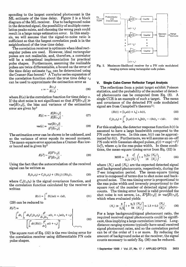
sponding to the largest correlated photocount is theML estimate of the time delay. Figure 2 is a blockdiagram of the ML receiver. Due to background noisein the detected signal, the possibility of multiple corre-lation peaks exists, and choosing the wrong peak couldresult in a large range estimation error. In this analy-sis, we will assume that the signal-to-noise ratio issufficient so that the largest correlation peak is in theneighborhood of the true time delay.
The correlation receiver is optimum when ideal rect-angular pulses are used. However, ideal rectangularpulses are not realizable, and, therefore, a correlatorwill be a suboptimal implementation for practicalpulse shapes. Furthermore, assuming the realizablepulses are twice differentiable, a bound on the error ofthe time delay estimate TML can be determined usingthe Cramer-Rao bound.3 A Taylor series expansion ofthe correlation function about the true time delay 'dcan be used to approximate the estimation error as
R(Td)(26)
where R (a) is the correlation function for time delay a.If the shot noise is not significant so that E2 [R(Td)] >>var[R('d)I, the bias and variance of the estimationerror are given by3
E[R(Td)]E[e] -E[R(rd)] (27)
vartel v-2[,.(rd)] (28)E [R(,rd)]
The estimation error can be shown to be unbiased, andso the variance of error equals its second moment.The mean-square error approaches a Cramer-Rao low-er bound and is given by3
E[~ _ E[R2 (rd)] (29)E2 [R(rd)]
Using the fact that the autocorrelation of the receivedsignal can be written as
R(t 1,t2) = C5(tlt 2) + (8(t 1))(S(t 2)), (30)
where C,(tl,t 2 ) is the signal covariance function, andthe correlation function calculated by the receiver iswritten
TR(r) = J S(t)a(t + T)dt, (31)
(29) can be reduced to
E[e2] 1
T T ' ~~a2
dti| dt2C(t1,t2) a(t, + Il)a(t2 + T2)
J T T2C5 d2 2[dft(St)--a(t + TO~Jo ]~~~~T1
2 Td
The square root of Eq. (32) is the rms timing error forthe correlation receiver using differentiable PN codepulse shapes.
RX
Signal
a (t-rk)
Fig. 2. Maximum-likelihood receiver for a PN code modulatedranging system using rectangular code pulses.
V. Single Cube-Corner Reflector Target Analysis
The reflections from a point target exhibit Poissonstatistics, and the probability of the number of detect-ed photocounts can be computed from Eq. (8). Asingle CCR is an example of such a target. The meanand covariance of the detected PN code modulatedsignal are from Campbell's theorem":
(S(t)) = [a(t) + Xb h(t),
C(t 14t2) = j [Xsa(T) + Xbh(t, - r)h(t2 - r)dT.
(33)
(34)
For this analysis, the detector response function h(t) isassumed to have a large bandwidth compared to thePN code waveform. In this case, h(t) can be approxi-mated by 6(t). Furthermore, we will assume an on-offPN code with Gaussian-shaped pulses, g(t) = exp(-t 2/2o ), where of is the rms pulse width. In these condi-tions, the mean-square timing error from Eq. (32) is
MSE8 __ -f1+ 3,-- (Nb)3 (N) k j16 (N))I (35)
where (N5) and (Nb) are the expected detected signaland background photocounts, respectively, during theT-sec integration period. The mean-square timingerror is composed of terms due to shot noise and back-ground noise. The rms timing error is proportional tothe rms pulse width and inversely proportional to thesquare root of the number of detected signal photo-counts. The timing error bound is valid provided theshot noise is not severe, i.e., E 2 [R(Td)] >> var[R(rd)],which when evaluated yields
8 493 (Nb)1 (Nb)(N,)» 1>I+ - 15+ 033a 64 (N5 )j ' N)
(36)
For a large background/signal photocount ratio, therequired received signal photocounts could be signifi-cant, thus implying a large correlation interval. Long-distance ranging systems typically have small receivedsignal photocount rates, and so the correlation periodcan be of the order of 1 s or more. By reducing theamount of background noise at the receiver, the signalcounts necessary to satisfy Eq. (36) can be reduced.
1 September 1988 / Vol. 27, No. 17 / APPLIED OPTICS 3653

Table 1. Parameters of a Satellite Laser Ranging System
Receiving system efficiency, 1 10%Receiver aperture area, AR 0.1 m2
Target reflectivity, a 0.5Altitude of the satellite, z 6000 kmLaser beam divergence, OT 100 AradTransmitted energy, ET 1 JCCR radius, r, 2.0 cmTransmit wavelength, X 800 nmAtmospheric transmittance, Ta 0.5Receiver optical bandwidth, AX 25 pmSpectral radiance, N(X) 25 W . m- 2 sr-' Am
A link analysis was performed for a single CCR tar-get located at a distance 6000 km from the receiver.This orbital range is comparable with that of the LaserGeodynamic Satellite (LAGEOS), an operational tar-get devoted to laser ranging measurements. The pa-rameters of the SLR are shown in Table I. The ex-pected number of signal photocounts detected by thereceiver in 1 s can be calculated from Eq. (19) to be-103.
A PN code of period 1023 chips is used as the rangingsignal and Gaussian pulses of rms width oy = T/4 areassumed, where T, is the chip duration and is equal to 1ns. A plot of the rms timing error (normalized to achip duration) vs received signal counts and integra-tion time in various received background strengths isshown in Fig. 3. To satisfy Eq. (36), the minimumnumber of received signal photocounts is of the orderof 100, which in turn determines the required integra-tion time. For T = 1 s and (N5 ) = (Nb), the normal-ized error is 2 X 10⁻², which results in a range error of-0.3 cm.
An estimate of the received background rate for thespecified link can be obtained by computing the re-ceived background power as' 3
P = N(G)AXARFov, (37)
where N(X) is the spectral radiance function, A\X is theoptical bandwidth of the receiver, AR is the receiverarea, and QFOV is the receiver solid-angle field of view.For daytime range measurements (worst case) andusing the receiver parameters from Table I, the re-ceived noise power is of the order of 1013 W. Using Eq.(7), the noise photocount rate is of the order of 104counts/s, 10 times greater than the expected receivedsignal count rate. Therefore, a better estimate of therms error is obtained using the top curve of Fig. 3. Inthis case, a 1-s integration time will yield an approxi-mate rms range error of 0.6 cm.
VI. Diffuse Target Analysis
For rough targets which comprise a sufficiently largenumber of independent scatters, the reflected energyis referred to as fully developed speckle, and its statis-tics are circularly complex Gaussian distributed. 9
The temporal characteristics of pulses reflected fromdiffuse ground targets and the ocean have been investi-gated both theoretically and experimentally.' 4-' 6
To illustrate the effect of target speckle on timedelay measurements, we will consider an infinite flat
CORRELATION TIME, T (sec)1n ,n1.-
o-
'0
o <N > O<Ns>
a:
0
101 103 10 ,)SIGNAL COUNT, <Ns>
Fig. 3. Normalized rms timing error vs received signal photocountsand correlation time for a single CCR target with X, = 3000 counts/s
and of= T,/4 = 0.25 ns.
\3arg~~~~oelRange Spred,
Laser
Fig. 4. Geometry of an infinite flat diffuse target and the incidentlaser beam.
diffuse target with uniform reflectivity. The targetwill be tilted by an angle with respect to the incidentlaser beam as shown in Fig. 4. The tilt will introducetime spread in the reflected signal and as a result willcontribute additional error in the time delay estimate.The rms time spread for an infinite flat diffuse targetat a range z from the transmitter has been found to beapproximately 7
2zCT = tanOT tano. (38)
If the laser footprint is assumed to have a Gaussiancross section and if background radiation is negligible,the mean and covariance of the detected PN coderange signal using Gaussian code pulses with idealdetection are given by
(S(t)) = (N)f 8(t),Cs(tlt 2 ) = (Ns)f 5 (t1)6(t 2 - t1 )
+ (N5 )2K-1d(t - t2)fsp t + ts
(39)
(40)
where
3654 APPLIED OPTICS / Vol. 27, No. 17 / 1 September 1988

10
:-
'0
a:
W
'2
0Z
102
IO-~
CORRELATION TIME, T (sec)
10° 101
)2D 103 id'SIGNAL COUNT, <N,>
102
105
Fig. 5. Normalized rms timing error vs received signal photocountsand correlation time for an infinite flat diffuse target with As = 3000
counts/s and Uf = aT = T,/4 = 0.25 ns.
MSt) = Ebig(t -iT - Td)' (41)i=0
g(t) = G( Uf + 0,t), (42)
K = nrAR(2 tanOT/X)2 , (43)
d(t) = E bie(t - iT, - Id), (44)i=o
e(t) = G(f 1af,t), (45)
f 5p(t) = G( fU/2 + AT, t). (46)
The waveforms f,(t) and fsp(t) are the normalized meanand the normalized speckle-induced variance, respec-tively, of the detected signal. The time spread due tothe target is assumed to be Gaussian shaped with rmswidth UT.
The optimum receiver correlates the detected signalwith delayed versions of the mean received signal andchooses the peak of the correlated output. However,for the diffuse target, the mean detected signal is notknown a priori by the receiver. So a suboptimal re-ceiver will correlate the detected signal with delayedversions of the known transmitted signal. Using Eqs.(32), (39), and (40), the mean square timing error forthe suboptimal receiver is
MSE 1 (f + AT)(2of + AT U(2af2 + 47
(N,) af(3af2 + 24)3/2 K 8Uf3( + )3/2
The first term in Eq. (47) is due to shot noise, and thesecond term is due to speckle. The effect of targetrange spread is apparent in both terms. The normal-ized rms timing error for the correlation receiver isplotted in Fig. 5 for several values of speckle SNR K.At low signal counts, the noise due to speckle is negligi-ble, and shot noise effects dominate the error. At highsignal levels, the error curves tend to saturate due tothe speckle. A typical value of K for this type of targetis several hundred or more.6 Assuming K = 1000, thenfrom Fig. 5, saturation occurs at a signal count of _104 .
Vil. Conclusions
In typical satellite laser ranging systems, high-ener-gy pulsed lasers are used to generate the ranging signal.In this paper, the ML estimator of signal arrival timewas derived for a PN code modulated laser diode rang-ing system. The performance of the estimator was
evaluated assuming Gaussian code pulses. The rangeaccuracy was calculated for the returns from a singleCCR target and taking into account received back-ground radiation. The target range was comparablewith that of the LAGEOS satellite. The range accura-cy is shot noise limited for negligible background. Asbackground noise increases, more received signal pho-tocounts are required to achieve a fixed range accura-cy, thus requiring a longer correlation period for eachrange measurement. For the tilted flat diffuse targetand assuming no background radiation, the range erroris a function of detector shot noise, target speckle, andtarget range spread. When signal levels are low, therange accuracy is shot noise limited. At large signallevels, speckle noise dominates ranging performance.Averaging several short-interval correlation measure-ments will improve the range accuracy for this target.For both targets analyzed, range accuracy of <1 cm canbe obtained with a correlation time of -1 s.
References
1. J. J. Degnan, "Satellite Laser Ranging: Current Status andFuture Prospects," IEEE Trans. Geosci. Remote Sensing GE-23, 398 (1985).
2. N. Takeuchi, H. Baba, K. Sakurai, and T. Ueno, "Diode-LaserRandom-Modulation cw Lidar," Appl. Opt. 25, 63 (1986).
3. I. Bar-David, "Communication under the Poisson Regime,"IEEE Trans. Inf. Theory IT-15, 31 (1969).
4. F. Davidson and L. Stephens, "Experimental Performance ofPoint Process Estimators of Optical Pulse Delay," IEEE Trans.Commun. COM-26, 1239 (1978).
5. B. M. Tsai and C. S. Gardner, "Time-Resolved Speckle Effectson the Estimation of Laser-Pulse Arrival Times," J. Opt. Soc.Am. A 2, 649 (1985).
6. K. E. Im and C. S. Gardner, "Estimation of the DifferentialPulse Propagation Times in Two-Color Laser Ranging Sys-tems," J. Opt. Soc. Am. A 3, 143 (1986).
7. F. J. MacWilliams and N. J. A. Sloane, "Pseudo-random Se-quences and Arrays," Proc. IEEE 64, 1715 (1976).
8. R. M. Gagliardi and S. Karp, Optical Communications (Wiley,New York, 1976).
9. J. W. Goodman, "Some Effects of Target-Induced Scintillationon Optical Radar Performance," Proc. IEEE 53, 1688 (1965).
10. C. S. Gardner and R. L. Gallawa, "Optical Communications," inReference Data for Engineers: Radio, Electronics, Computer,and Communications (SAMS, Indianapolis, 1985).
11. P. O. Minott, M. W. Fitzmaurice, J. B. Abshire, and H. E. Rowe,"Prelaunch Testing of the GEOS-3 Laser Reflector Array,"NASA Tech. Paper 1138 (Jan. 1978).
12. A. Papoulis, "Estimation of the Average Density of a Nonuni-form Poisson Process," IEEE Trans. Commun. COM-22, 162(1974).
13. N. S. Kopeika and J. Bordogna, "Background Noise in OpticalCommunication Systems," Proc. IEEE 58, 1571 (1970).
14. B. M. Tsai and C. S. Gardner, "Remote Sensing of Sea StateUsing Laser Altimeters," Appl. Opt. 21, 3932 (1982).
15. J. B. Abshire and J. F. McGarry, "Two-Color Short-Pulse LaserAltimeter Measurements of Ocean Surface Backscatter," Appl.Opt. 26, 1304 (1987).
16. K. E. Im, C. S. Gardner, J. B. Abshire, and J. F. McGarry,"Experimental Evaluation of the Performance of Pulsed Two-Color Laser-Ranging Systems," J. Opt. Soc. Am. A 4,820 (1987).
17. C. S. Gardner, "Target Signatures for Laser Altimeters: anAnalysis," Appl. Opt. 21, 448 (1982).
1 September 1988 / Vol. 27, No. 17 / APPLIED OPTICS 3655
I I .
2 _ _ _ K ~~~~~~~~1000 _
3~~~~~~~~~~~~~~00 _