satellite communications syllabus
TRANSCRIPT
1
SATELLITE COMMUNICATIONS
SYLLABUS
UNIT-I:
Communication Satellite: Orbit and Description: A brief History of Satellite
Communication, Satellite Frequency bands, Satellite Systems, Applications, Orbital Period
and Velocity, Effects of Orbital inclination, Azimuth and Elevation, Coverage and Slant
range, Eclipse, Orbital perturbations , Placement of a Satellite in a Geo-Stationary Orbit.
UNIT-II:
Satellite Sub-Systems: Altitude and orbit control system, TT&C Sub-System, Altitude
control Sub-System, Power Systems, Communication Subsystems, Satellite antenna
Equipment.
Satellite Link: Basic transmission theory, system noise temperature and G/T ratio, Basic
Link Analysis, Interference Analysis, Design of satellite links for specified C/N, (with and
without frequency Re-use), Link Budget.
UNIT-III:
Propagation effects: Introduction, Atmospheric Absorption, Cloud Attenuation,
Tropospheric and Ionospheric Scintillation and Low angle fading, Rain Induced attenuation,
rain induced cross polarization interference.
Multiple Access: Frequency Division Multiple Access(FDMA), Intermodulation,
Calculation of C/N. Time Division Multiple Access(TDMA), Frame structure, Burst
structure, Satellite Switched TDMA Onboard processing, Demand Assignment Multiple
Access (DAMA) – Types of Demand Assignment, Characteristics, CDMA Spread Spectrum
Transmission and Reception.
UNIT-IV:
Earth Station Technology: Transmitters, Receivers, Antennas, Tracking systems, Terrestrial
Interface, Power Test methods, Lower Orbit Considerations.
Satellite Navigation & Global Positioning Systems: Radio and Satellite Navigation, GPS
Position Location principles, GPS Receivers, GPS C/A code accuracy, Differential GPS.
UNIT-V:
Satellite Packet Communications: Message Transmission by FDMA: M/G/1 Queue,
Message Transmission by TDMA, PURE ALOHA-Satellite Packet Switching, Slotted Aloha,
Packet Reservation, Tree Algorithm.
TEXT BOOKS:
1. Satellite Communications- Timothy Pratt, Charles Bostian and Jeremy Allnutt, WSE,
Wiley Publications, 2nd
Edition, 2003, John Wiley & Sons.
2. Satellite Communication Engineering- Wilbur L. Pritchand, Robert A Nelson and
Henri G.Suyderhoud, 2nd
Edition, Pearson Publications.
3. Digital Satellite Communications-Tri. T.Ha, 2nd
Edition, 1990, Mc. Graw Hill.

2
REFERENCE BOOKS:
1. Satellite Communications- Dennis Roddy, 2nd Edition, 1996, McGraw Hill.
2. Satellite Communications: Design Principles- M. Richharia, 2nd
Edition,BS
Publications, 2003.
3. Digital Satellite Communications-Tri. T. Ha,2nd
Ed.,MGH,1990.
4. Fundamental of Satellite Communications- K. N Raja Rao, PHI, 2004
UNIT-III
PROPAGATION EFFECTS – MULTIPLE ACCESS
Atmoshperic Lossess
Radio propagation is the behavior of radio waves when they are transmitted, or propagated
from one point on the Earth to another, or into various parts of the atmosphere. As
a form of electromagnetic radiation, like light waves, radio waves are affected by the
phenomena of reflection, refraction, diffraction, absorption, polarization and scattering.
Radio propagation is affected by the daily changes of water vapor in the troposphere and
ionization in the upper atmosphere, due to the Sun. Understanding the effects of varying
conditions on radio propagation has many practical applications, from choosing frequencies
for international shortwave broadcasters, to designing reliable mobile telephone systems, to
radio navigation, to operation of radar systems.
Multiple losses occur due to the Earth’s atmosphere. Losses maybe because of the
adverse weather conditions or because of the energy absorption done by the various
gases present in the atmosphere. Weather related losses are called “atmospheric
attenuation”. Absorption losses are called “atmospheric absorption”.
At various frequencies, different components of atmosphere cause impairments to
the radio wave signals.
Example: water vapour at 22.3 GHz and oxygen (O2) at 60 GHz.
Considering the elevation angle of signals as 100 and absorption loss at [AA]90
decibels. Formula for absorption loss is:
[AA] = [AA]90 cosec θ
Where θ is the elevation angle
A fading phenomenon, which causes the radio waves to focus and defocus
because of the differences in the atmospheric refraction index is seen. This effect is
called “atmospheric scintillation”.
3
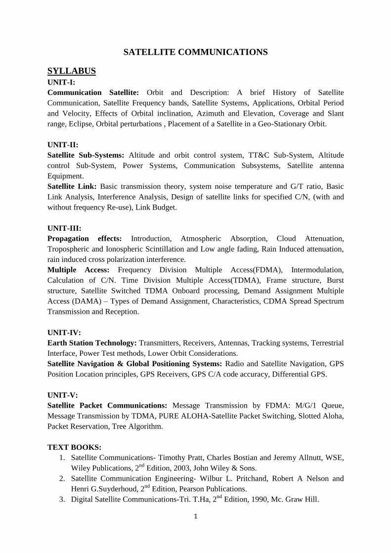
Fig 3.1: Layers of Earth’s Atmosphere
Ionospheric Effects
Ionosphere is one of the layers in the Earth’s atmosphere. It is situated between 90 km to
400 km above the surface of the Earth. All the communication signals between satellites and
earth stations have to pass through this layer.
This layer contains free electrons which are charged due to solar radiation. These ions
are not uniformly distributed across the ionosphere, but move together across the ionosphere
in clusters. Such clusters are called clouds of electrons or “travelling ionosphere
disturbances”. When signals pass through such electron clouds, fluctuations are caused.
Electron clouds are created when accelerated charged particles disturb stray
electrons already floating in the atmosphere, and bounce or slingshot the electrons
into each other and the passing by signals. These stray electrons can be photo-electrons from
synchrotron radiation or electrons from ionized gas molecules and have adverse effect on
the signals passing through them especially if the density of these clouds is high.
The other effects seen on the signal also includes scintillation, absorption, propagation
delay, dispersion, and frequency change and polarization rotation. These effects decrease
as the frequency increases. Out of the above effect only scintillation and polarization
rotation are of major concern for satellite communication.
Absorption: Electromagnetic waves are absorbed in the atmosphere according to wavelength.
Two compounds are responsible for the majority of signal absorption: oxygen (O2) and
water. It is seen for frequencies at 22 GHz due to water, and at 63 GHz due to oxygen.
The concrete amount of water vapour and oxygen in the atmosphere normally declines with
an increase in altitude because of the decrease in pressure.

4
Figure 3.2 : Average atmospheric absorption of millimeter waves.
A: Sea level ; T = 20°C; P = 760mm; PH2O = 7.5g/m3.
B : 4 km (13000 ft); T = 0°C; PH2O = 1g/m3 .
Propagation Delay: Propagation delay is the time required for a signal to travel from the
sender (in our case from an earth station or a spacecraft) to the receiver. It is measured in
microsecond. As distances are very much greater than those involved with terrestrial systems,
propagation delay can be an issue, especially for satellites using geostationary orbits. Here the
round trip from the ground to the satellite and back can be of the order of a quarter of a
second.
Dispersion: Here the signals are distributed over a wide area.
Polarization Rotation: It is the phenomenon in which waves of light or other radiation are
restricted in direction of vibration.
Scintillation: it is the variation in the amplitude, phase, polarization, angle of arrival
of radio waves. They are caused by the irregularities in the ionosphere which change with
time. Fading of signal is the major effect o ionosphere scintillation. The effect of fading
can sometimes be very severe and may last upto several minutes.
Rain Attenuation
The rate at which the rain water would get accumulated in a rain gauge in the area of
interest is called rain rate. Rain attenuation for a given frequency is a function of rain
rate. It is calculated in percentage time. A percentage time is generally of a year.
Multiple Access
Multiple access is defined as the technique where in more than one pair of earth stations can
simultaneously use a satellite transponder. It is a technique used to explore the satellite’s
geometric advantages and is at the core of satellite networking. The basic form of multiple
access employed by all communications satellites is the use of many transponders. A large
GEO satellite may have a communication bandwidth of over 2000 MHz within an allocated
spectrum of 500 MHz. Through frequency reuse with multiple antenna beams and orthogonal
5
polarization, the spectrum can be reused several times over –as many as seven times in the
case of INTELSAT IX satellites. The frequency spectrum used by the satellite is divided into
smaller bandwidths which are allocated to transponders, allowing separate communication
links to be established via the satellite on the basis of transmit frequency. Transponder
bandwidths of 36, 54 and 72 MHz have been commonly employed on GEO satellites.
Multiplexing: It is the process of combining a number of signals into a single signal
Multiple Access: It is the technique where in more than one pair of earth stations can
simultaneously use a satellite transponder.
The designer of a satellite communication system must take decisions about the form of
multiple access to be used. The multiple access technique will influence the capacity and
flexibility of the satellite communication system, its cost, and its ability to earn revenue. The
basic problem in any multiple access system is how to permit a changing group of earth
stations to share a satellite in such a way that satellite communication capacity is maximised.
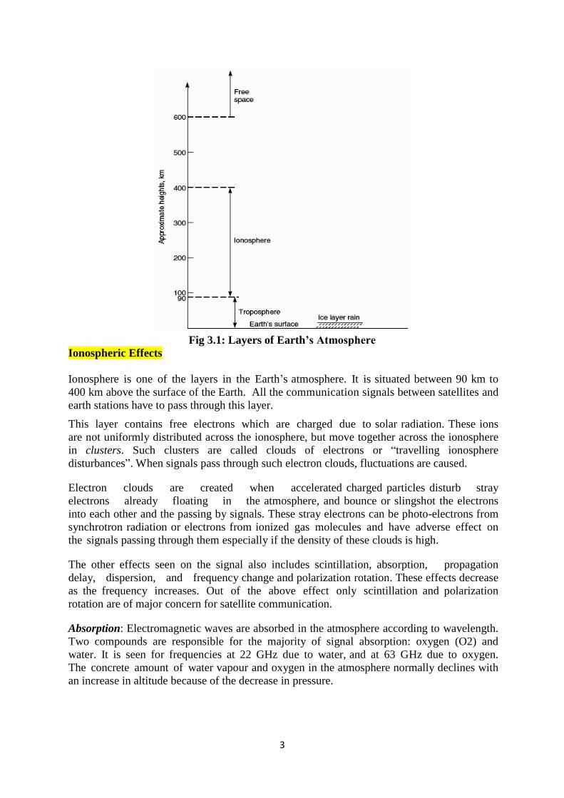
FIG 3.3: Multiple Access Techniques FDMA, TDMA and CDMA
There are three basic multiple access techniques, illustrated in Figure 3.3. In Frequency
Division Multiple Access (FDMA) all users share the satellite at the same time, but each user
transmits at unique allocated frequency. This approach
In a wireless communication system, radio resources must be provided in each cell to
assure the interchange of data between the mobile terminal and the base station. Uplink
is from the mobile users to the base station and downlink is from the base station to the
mobile users. Each transmitting terminal employs different resources of the cell. A
multiple access scheme is a method used to distinguish among different simultaneous
transmissions in a cell. A radio resource can be a different time interval, a frequency
interval or a code with a suitable power level.
All these characteristics (i.e., time, frequency, code and power) univocally contribute to
identify a radio resource. If the different transmissions are differentiated only for the
6
frequency band, we have the Frequency Division Multiple Access (FDMA). Whereas, if
transmissions are distinguished on the basis of time, then they are consider the Time
Division Multiple Access (TDMA). Finally, if a different code is adopted to
separate simultaneous transmissions, we have the Code Division Multiple Access
(CDMA).
However, resources can be also differentiated by more than one of the above aspects.
Hence, hybrid multiple access schemes are possible (e.g., FDMA/TDMA). In a satellite
communication, radio resources can be re-used between sufficiently far stations,
provided that the mutual interference level is at an acceptable level.
This technique is adopted by FDMA and TDMA air interface, where the reuse is
basically of carriers. In the CDMA case, the number of available codes is so high that
the code reuse among cells (if adopted) does not increase the interference. In uplink, a
suitable Medium Access Control (MAC) protocol is used to regulate the access of
different terminals to the resources of a cell that are provided by a multiple access
scheme.
Comparison with other multiple-access schemes
In radio systems, TDMA is usually used alongside Frequency-Division Multiple Access
(FDMA) and Frequency Division Duplex (FDD); the combination is referred to as
FDMA/TDMA/FDD. This is the case in both GSM and IS-136 for example. Exceptions to
this include the DECT and PHS micro-cellular systems, UMTS-TDD UMTS variant, and
China's TD-SCDMA, which use Time Division Duplexing, where different time slots are
allocated for the base station and handsets on the same frequency.
A major advantage of TDMA is that the radio part of the mobile only needs to listen and
broadcast for its own time slot. For the rest of the time, the mobile can carry out
measurements on the network, detecting surrounding transmitters on different frequencies.
This allows safe inter frequency handovers, something which is difficult in CDMA systems,
not supported at all in IS-95 and supported through complex system additions in Universal
Mobile Telecommunications System (UMTS). This in turn allows for co-existence of
microcell layers with macro cell layers.
CDMA, by comparison, supports "soft hand-off" which allows a mobile phone to be in
communication with up to 6 base stations simultaneously, a type of "same-frequency
handover".
The incoming packets are compared for quality, and the best one is selected. CDMA's "cell
breathing" characteristic, where a terminal on the boundary of two congested cells will be
unable to receive a clear signal, can often negate this advantage during peak periods. A
disadvantage of TDMA systems is that they create interference at a frequency which is
directly connected to the time slot length. This is the buzz which can sometimes be heard if a
TDMA phone is left next to a radio or speakers. Another disadvantage is that the "dead time"
between time slots limits the potential bandwidth of a TDMA channel. These are
implemented in part because of the difficulty in ensuring that different terminals transmit at
exactly the times required. Handsets that are moving will need to constantly adjust their
timings to ensure their transmission is received at precisely the right time, because as they

7
move further from the base station, their signal will take longer to arrive. This also means that
the major TDMA systems have hard limits on cell sizes in terms of range, though in practice
the power levels required to receive and transmit over distances greater than the supported
range would be mostly impractical anyway.
Frequency Division Multiple Access (FDMA)
FDMA was the first multiple access technique used in satellite communication systems. The
analog Frequency Division Multiplexing (FDM) is now obsolete but it was the primary
method of multiplexing telephone channels for transmission over terrestrial cable or
microwave links for about 50 years. The FDM-FM RF carrier was transmitted to the satellite,
where it shared a transponder with other carriers using FDMA. The technique is known as
FDM-FM-FDMA, and was the preferred method for the transmission of telephone channels
over Intelsat satellite for more than 20 years. The main advantage of FDMA is that filters can
be used to separate signals. Filter technology was well understood when satellite
communications began, and microwave filters were used in earth stations to separate the
FDMA signals within a given transponder.
Intermodulation
Intermodulation products are generated whenever more than one signal is carried by a
nonlinear device. Filtering can be used sometimes to remove the intermodulation products,
but if they are within the bandwidth of the transponder they cannot be filtered out. The
saturation characteristic of a transponder can be modelled by a cubic curve to illustrate the
generation of third-order intermodulation. Third-order intermodulation is important because
third-order intermodulation products often have frequencies close to the signal that generate
the intermodulation and therefore likely to be within the transponder bandwidth.
To illustrate the generation of third-order intermodulation products, we will model the
nonlinear characteristic of the transponder HPA with a cubic voltage relationship and apply
two unmodulated carriers at frequencies f1 and f2 at the input of the amplifier.
Vout = A Vin + b (Vin)3
Where A>>b
The amplifier input signals is V1 cosω1t + V2 cosω2t
Vout = AV1 cosω1t + AV2 cosω2t + B[V1 cosω1t + V2 cosω2t]3
The above equation is a combination of linear and non-linear terms.
The non-linear term which will be denoted as V3out, can be expanded as
V3out = [V1 cosω1t + V2 cosω2t]3 =
{V1
3 cos
3ω1t + V2
3 cos
3ω2t }+ {2 V2
2 cos
2ω2t x V2 cosω2t
+ 2 V22 cos
3ω2t x V1 cosω1t}
The first two terms contain frequencies f1, f2, 3f1, and 3f2. The triple frequency components
can be removed from the amplifier output with band-pass filters. The second two terms
generate the third order intermodulation frequency components. The second two terms yield
components such as 2f1-f2, and 2f2-f1 which may fall within the transponder bandwidth. These
two terms are known as the third-order intermodulation.
Calculation of C/N with Intermodulation
8
Intermodulation between carriers on a nonlinear transponder adds unwanted products into the
transponder bandwidth that are treated as though the interference were Gaussian noise. For
wideband carriers, the behaviour of the Intermodulation products will be noise like; with
narrowband carriers, the assumption may not be accurate, but is applied because of the
difficulty of determining the exact nature of the Intermodulation products.
The output backoff of a transponder reduces the output power level of all carriers, which
therefore reduces the C/N ratio in the transponder. The transponder C/N ratio appears as
(C/N)up in the calculation of the overall(C/N)o ratio in the earth station receiver.
Intermodulation noise in the transponder is defined by another C/N ratio, (C/N)IM, which
enters the overall (C/N)o ratio through the reciprocal formula (using linear C/N power ratios)
(C/N)o = 1/ [1/(C/N)up + (C/N)dn + (C/N)IM]
Techniques for calculation of (C/N)IM require full knowledge of transponder non-linearity and
the signals carried by the transponder.
TIME DIVISION MULTIPLE ACCESS (TDMA)
In TDMA a number of earth stations take turns transmitting bursts of RF signals through a
transponder. Since all practical TDMA systems are digital, TDMA has all the advantages
over FDMA that digital signals have over analog. TDMA systems can be divided by time, are
easily reconfigured for changing traffic demands, are resistant to noise and interference, and
can readily handle mixed voice, video, and data traffic. One major advantage of TDMA when
using the entire bandwidth of a transponder is that only one signal is present in the
transponder at one time, thus overcoming many of the problems caused by nonlinear
transponders operating with FDMA. However using all of the transponder bandwidth requires
every earth station to transmit at a high bit rate, which requires high transmitter power, and
TDMA is not well suited to narrow band signals from small earth stations. Nonlinearity in the
transponder can cause an increase in inter-symbol interference with digital carriers;
equalizers can be used at the receiving earth stations to mitigate the effect.
In TDMA groups of bits are taken from each of the bit streams and formed into baseband
packages or frames that also contain synchronization and identification bits. At a receiving
earth station, the high speed bit stream must first be recovered, which requires demodulation
of the RF carrier, generation of bit clock, sapling of the received waveform, and recovery of
the bits. The synchronization bits or words in the packets or frames must then be found so
that the high-speed bit stream can be split into its original lower speed signals. The clock
frequency for the bit stream is fixed, and the frame length is usually constant. Packet lengths
can vary, however, which is the main difference between frames and packets. The entire
process requires considerable storage of bits so that the original signals can be rebuilt, leading
to delays in transmission. In a GEO satellite system, the largest delay is always the
transmission time to the satellite and back to earth typically 240 ms. The transmission delay
is unavoidable, but any additional delays should be minimized.
Burst transmission
TDMA is an RF multiple access technique that allows a single transponder to be shared in
time between RF carriers from different earth stations. In a TDMA system, the RF carrier
from each earth station sharing a transponder is sent as a burst at a specific time. At the
satellite, bursts from different earth stations arrive sequentially, so the transponder carries a

9
near continuous signal made up of a sequence of short bursts coming from different earth
stations.
The burst transmission is assembled at a transmitting earth station so that it will correctly fit
into the TDMA frame at the satellite. The frame has a length from 125 µs to many
milliseconds, and the burst from the earth station must be transmitted at the correct time to
arrive at the satellite in the correct position within the TDMA frame. This requires
synchronization of all earth stations in a TDMA network, adding considerable complexity to
the equipment at the transmitting station. Each station must know exactly when to transmit,
typically within a microsecond, so that the RF bursts arriving at the satellite from different
earth stations do no overlap.
A receiving earth station must synchronize its receiver to each of the sequential bursts in the
TDMA signal and recover the transmission from each uplink earth station. The uplink
transmissions are then broken down to extract the data bits, which are stored and reassembled
into their original bit streams for onward transmission. The individual transmission from
different uplink earth stations are usually sent using BPSK or QPSK and will inevitably have
small differences in carrier and clock frequencies, and different carrier phases. The receiving
earth station must synchronize its PSK demodulator to each burst of signal within a few
microseconds, and then synchronize its bit clock in the next few microseconds so that a bit
stream can be recovered.
TDMA frame structure
A TDMA frame contains the signals transmitted by all the earth station in a TDMA network.
It has a fixed length, and is built up from the burst transmissions of each earth station, with
guard times between each burst. The frame exists only in the satellite transponder and on the
down links from the satellite to the receiving earth stations. Figure 3.4 below shows a
simplified diagram of a TDMA frame for four transmitting earth stations. Each station
transmits a preamble that contains synchronization and other data essential to the operation of
the network before sending data. The earth station’s transmission is followed by a guard time
to avoid possible overlap of the following transmission. In GEO satellite systems, frame
lengths of 125 µs upto 20 ms have been used.
Fig 3.4 : TDMA frame with four transmitting earth stations

10
Satellite Switched TDMA
One advantage that TDMA has when used with a baseband processing transponder is satellite
switched TDMA. Instead of using a single antenna beam to maintain continuous
communication with its entire coverage zone, the satellite has a number of narrow antenna
beams that can be used sequentially to cover the zone. A narrow antenna beam has higher
beams that can be used sequentially to cover the zone. A narrow antenna beam has a higher
gain than a broad beam, which increases the satellite EIRP and therefore increases the
capacity of the downlink. Uplink signals received by the satellite are demodulated to recover
the bit streams, which are structured as sequence of packets addressed to different receiving
earth stations. The satellite creates TDMA frames of data that contain packets addressed to
specific earth stations, and switches its transmit beam to the directions of the receiving earth
station as the packets are transmitted. Note that control of the TDMA network timing could
now be on board the satellite, rather than at a master earth station.
On board processing
The discussion of multiple access so far has assumed the use of a bent pipe transponder,
which simply amplifies a signal from earth and retransmits it back to earth at a different
frequency. The advantage of a bent pipe transponder is flexibility. The transponder can be
used for any combination of signals that will fit within its bandwidth. The disadvantage of the
bent pipe transponder is that it is not well suited to uplinks from small stations, especially
uplinks operating in Ka band. Consider a link between a small transmitting earth station and a
large hub station via a bent pipe GEO satellite transponder. There will usually be a small rain
fade margin on the uplink from the transmitting station because of its low EIRP. When rain
affects the uplink, the C/N ratio in the transponder will fall. The overall C/N ratio in the hub
station receiver cannot be greater than the C/N ratio in the transponder, so the bit error rate at
the hub station will increase quickly as rain affects the uplink. The only available solution is
to use forward error correction coding on the link which lowers the data throughput but is
actually needed for less than 5% of the time.
Satellite Switched TDMA with Onboard Processing
Baseband processing is essential in satellites using satellite switched TDMA, because data
packets must be routed to different antenna beams based on the address of the destination
earth station. The data in such systems is always sent in packets which contain a header and a
traffic section. The header contains the address of the originating station and the address of
the destination earth station. When satellite switched TDMA is used, the transponder must
extract the destination information and use it to select the correct downlink beam to that
pocket. The satellite is operating much like a router in a terrestrial data transmission system.
Switched beam operation of an uplink from a small earth station is more difficult to achieve
because it requires synchronization of the earth station transmit time with the satellite beam
pointing sequence, in much the same way that a TDMA uplink operates. However, the uplink
can operate in a small bandwidth which overcomes the chief disadvantage of classic TDMA-
the requirement for high burst rate transmission and high transmit power.
Satellite switched TDMA can greatly increase the throughput of a transponder. Consider for
example, a satellite providing Internet access to individual users in the US. The uplink and
downlink beams at the satellite must provide coverage over an area approximately 6o x 3
o, as

11
seen from the satellite. This limits the maximum achievable satellite antenna gain to
approximately 32.5 dB.
A satellite with switched beam capability can have much narrower beams with higher gain
than a satellite with a single fixed beam. The limitation on gain is the diameter of the antenna,
which must fit inside the launch vehicle shroud. For launchers available in 2000 this limit is
about 3.5 m. At 20 G Hz, the uplink frequency for Ka band, and antenna with a circular
aperture of diameter D= 3.5 m and aperture efficiency of η = 65% has a gain G= η (πD/λ)2 =
55.4 dB, and its beamwidth is approximately 75λ/D = 0.32o. The corresponding down link
antenna for 30 G Hz that has a beamwidth of 0.32o and a gain of 55.4 dB has a diameter of
2.33 m. The switched beam satellite has an antenna gain almost 23 dB higher than the single
beam satellite, which can be traded directly for reduction in uplink or downlink transmit
power, and uplink or downlink data rate. However, the satellite must generate at least 170
beams to cover all of US with 0.32o beams, with a consequent increase in satellite antenna
complexity.
Demand Assignment Multiple Access (DAMA)
Demand access can be used in any satellite communication link where traffic from an earth
station is intermittent. An example is an LEO satellite system providing links to mobile
telephones. Telephone voice users communicate at random times, for periods ranging from
less than a minute to several minutes. As a percentage of total time, the use of an individual
telephone may be as little as 1%. If each user were allocated a fixed channel, the utilization of
the entire system might be as low as 1%, especially at night when demand for telephone
channels is small. Demand access allows a satellite channel to be allocated to a user on
demand, rather than continuously, which greatly increases the number of simultaneous users
who can be served by the system. The two-way telephone channel may be a pair of frequency
slots in a DA-SCPC system, a pair of time slots in a TDM or TDMA system, or any
combination or FDMA, TDM, and TDMA. Most SCPC-FDMA systems are demand access
to ensure that the available bandwidth in transponder is used as fully as possible.
Types of Demand Assignment, Characteristics
Demand access system require two different types of channel; a common signalling
channel(CSC) and a communication channel. A user wishing to enter the communication
network first calls the controlling earth station using the CSC, and the controller then
allocates a pair of channels to that user. The CSC is usually operated in random access mode
because the demand for use of CSC is relatively low, messages are short, and the CSC is
therefore lightly loaded, a requirement for any DA link. Packet transmission techniques ar
widely used in demand access systems because of the need for addresses to determine the
source and destination of signals.
CDMA Spread Spectrum Transmission and Reception.
Code Division Multiple Access is a scheme in which a number of users can occupy all of the
transponder bandwidth all of the time. CDMA signals are encoded such that information from
an individual transmitter can be recovered by a receiving station that knows the code being
used, in the presence of all the other CDMA signals in the same bandwidth. This provides a
decentralized satellite network, as only the pairs of earth stations that are communicating
need to coordinate their transmissions. Subject to transponder power limitations and the

12
practical constraints of the codes in use, stations with traffic can access a transponder on
demand without coordinating their frequency or their time of transmission with any central
authority. Each receiving station is allocated a CDMA code; any transmitting station that
wants to sent data to that earth station must use the correct code. CDMA codes typically 16
bits to many thousands of bits in length, and the bits of a CDMA code are called chips to
distinguish them from the message bits of a data transmission. The CDMA chip sequence
modulates the data bits of the original message, and the chip rate is always much greater than
the data rate. This greatly increases the speed of the digital transmission, widening its
spectrum in proportion to the length of the chip sequence. As a result, CDMA is also known
as spread spectrum. Direct Sequence Spread Spectrum (DSSS) is the only type currently used
in satellite communication; frequency hopping spread spectrum(FH-SS) is used in the
Bluetooth system for multiple access in short range local area wireless networks.
Spread Spectrum Transmission and Reception
This discussion of CDMA for satellite communications will be restricted to direct sequence
systems, since that is the only form of spread spectrum that has been used by commercial
satellite systems to date. The spreading codes used in DS-SS CDMA systems are designed to
have good autocorrelation properties and low cross-correlation. Various codes have been
developed specifically for this purpose, such as Gold and Kasami codes.
The DS-SS codes will all be treated as pseudonoise (PN) sequences in this discussion.
Pseudonoise refers to the spectrum of code, which appears to be a random sequence of bits
(or chips) with a flat, noiselike spectrum. The generation of a DS-SS signal is illustrated in
Figure 6.16 we will begin by assuming that the system uses baseband signals .Most DS-SS
systems generate spread spectrum signals using BPSK modulated versions of the data stream,
but it is easier to see how a DS-SS system operates if the signals are first considered at
baseband. In Figure 6.16, a bit stream containing traffic data at a rate Rb converted to have
levels of +1 and -1 V corresponding to the logical states 1 and 0, is multiplied by a PN
sequence, also with levels +1 and -1V, at a rate M x Rb chips per second. Each data bit
results in the transmission of a complete PN sequence of length M chips.

13
Fig 3.4: The basic principle of a direct sequence spread spectrum(CDMA) system. Each
incoming message data bit is multiplied by the same PN sequence. In this example the
message sequence is -1 +1 and the PN sequence is +1 +1 +1 -1 +1 -1 -1.
In the examples shown in Figure 3.4 the seven chip spreading code sequence is
1110100,which is converted to +1+1+1-1+1-1-1. The spreading sequence multiplies the data
sequence 0 1, represented as -1+1,leading to the transmitted sequence-1-1-1+1-1+1+1+1-
1+1-1-1 shown at the right in Figure 3.4 Recovery of the original data stream of bits from the
DS-SS signal is achieved by multiplying the received signal by the same PN code that was
used to generate it. The process is illustrated in Figures 3.4 and 3.5.

14
Fig 3.5: Data bit recovery using an IF correlator (matched filter). In this example the PN
sequence is seven bits long for illustration. The CDMA chips from the receiver are clocked
into the shift register serially and the shift register contents passed through phase shifters
and added. The phase shifters convert -1 chips to +1 when the correct code is in the shift
register such that all the voltages add to a maximum when the received sequence is correct.
This figure shows the shift register contents and adder output for the chip sequence in Fig
3.4. Note that a high spurious output of 5 occurs at the third clock step, indicating that the
seven bit sequence used here for illustration has poor auto correlation properties.

15
Fig 3.6: A baseband correlator for dispreading CDMA signals. The original bit stream is
recovered by multiplying the received signal by a synchronized copy of the PN sequence that
was used in the transmitter.
At a CDMA receiver which Knows the the seven bit code; there will be a correlator that has
the code stored as multiplier settings. Figure 3.5 illustrates the correlation process. Received
chips are clocked into a shift register of length equal to the code sequence seven stages in this
case. The word in the shift register is identified as b1 b2.... b1. At each clock cycle the seven
chip word with chip values bi in the correlator shift register are multiplied by +1 or -1,
corresponding to the chips in the code sequence, by the blocks marked phase shifters in
Figure 3.5.Note that received chips are clocked in to the correlator from the left, so the code
sequence appears reversed (written from right to left) in the phase shifters in Figure 3.5.The
outputs of the phase shifters are added to give the output word v0 =
p1b1+p2b2+p3b3+p4b4+p5b5+p6b6+p1b1. The value of v0 will be +7 or -7 when the correct code
sequence exactly fills the seven stages of the shift register.
Figure 3.5 shows one process by which the code sequence can be detected .The shift register
is originally filled with +1 chips, giving an output from the adder of vo= +1. The sequence
generated in Figure 3.4 is clocked in from the left. The adder output yields values of v0
=1+5+3+3+1-1as the chip sequence moves into the register. on the next clock cycle ,when all
seven bits the sequence are in the seven stage register, the output of the adder is -7.A
threshold detector after the adder with a threshold level of -6 would detect the threshold
crossing and output a logical 0 for the first data bit. As the next 7 bits are clocked through the
shift register, the output of the adder fluctuates between -1 and +5, reaching v0 =+7 or-7
when the code sequence fills the shift register Note that the seven bit sequence used for
illustration here would be a poor choice for a CDMA system because of the high spurious
output from the adder at the third clock step.PN sequences used in CDMA systems are
required to have good autocorrelation and good cross-correlation properties to minimize false
threshold crossings. Multiple shift registers like the one shown in Figure 6.17 can be operated

16
in parallel with each input delayed by an increment of one bit. If there are N shift registers N
possible code positions are tested at each chip clock cycle giving faster code acquisition.
When the code sequence is long, the multistage shift register detector shown in Figure 3.5
becomes unwieldy. Chip-by-chip multiplication is used instead. The multiplier has inputs bi
and pi where bi is the received chip and pi is a stored PN sequence chip. The output of the
multiplier is then integrated over the duration of the code sequence to yield a value +N-N
where N is the number of chips in the PN sequence. The process is illustrated in Figure 3.6
for the seven chip code of Figure 3.4 The incoming signal at the left side of the Figure is
multiplies by the dispreading code sequence to give the output at the right of the Figure In
practice, a low pass filter is used instead of an integrator to avoid the need to synchronize
discharge (dumping) of the integrator contents when a bit is detected if the correct code is
present in the input signal. The output of the multiplier is +1 or -1 as each chip is present in
the multiplier. In a practical DS-SS CDMA system, there will be several other CDMA signal
present at the correlator input as well as the wanted code. The integrated value of the
multiplier output for cross-correlation of any other code with the stored code will yield a
value +1 or -1 if the codes have ideal cross correlation properties Given a sufficiently large
value for M (i e ., a long PN code sequence), it is possible to detect the bits of the wanted
code in the presence of large number of unwanted CDMA signals.