sat5g (761413) d5.6 march 2020 satellite and terrestrial
TRANSCRIPT
SaT5G (761413) D5.6 March 2020
D5.6
Results and Recommendations from SaT5G Demonstrations and Validations
Topic ICT-07-2017
Project Title Satellite and Terrestrial Network for 5G
Project Number 761413
Project Acronym SaT5G
Contractual Delivery Date M29
Actual Delivery Date 17th March 2020
Contributing WP WP5
Project Start Date 01/06/2017
Project Duration 30 months
Dissemination Level Public
Editor UoS
Contributors IDR, I2CAT, OA, TAS, TNO, UOS, ZII, UOULU
Satellite and Terrestrial
Network for 5G

SaT5G (761413) D5.6 March 2020
Page 2 of 39
Contributors
Name Organisation Contributions include
Michael Fitch UoS Overall editor
Barry Evans UoS 5GIC results and review
Simon Watts AVA Recommendations and review
Leonardo Goratti ZII ZII results and review
Harri Saarnisaari Oulu Oulu results and review
Document History
Version Date Modifications Source
0.1 2019-07-16 Initial table of content TAS
0.2 2020-03-12 Updating of all sections UoS
1.0 2020-03-16 Final edits following review UoS

SaT5G (761413) D5.6 March 2020
Page 3 of 39
Table of Contents
List of Figures .......................................................................................................................................... 4
List of Tables ........................................................................................................................................... 5
List of Acronyms ...................................................................................................................................... 6
Executive Summary ................................................................................................................................ 8
1 Introduction ...................................................................................................................................... 9
2 Context ........................................................................................................................................... 10
2.1 General .................................................................................................................................. 10
2.2 Validation of project use-cases, architecture design and research pillars ............................ 11
2.2.1 Use-cases ......................................................................................................................... 11
2.2.2 Architecture ....................................................................................................................... 11
2.2.3 Research pillars ................................................................................................................. 14
2.3 5GPPP KPI validation on testbeds ....................................................................................... 18
3 Proof of concept of satellite integration into 5G ............................................................................. 20
3.1 5GIC testbed results ............................................................................................................. 20
3.1.1 Communications chain ...................................................................................................... 20
3.1.2 Multicast results ................................................................................................................. 21
3.1.3 Multi-linking results ............................................................................................................ 23
ZII testbed .................................................................................................................................. 28
3.2 ...................................................................................................................................................... 28
3.2.1 MEO satellite link............................................................................................................... 28
3.2.2 GEO satellite ..................................................................................................................... 31
3.2.3 Multicast performance measurements .............................................................................. 33
3.2.4 Virtualised Services Creation Time ................................................................................... 34
3.2.5 Control Plane Measurements ............................................................................................ 35
3.3 Oulu testbed .......................................................................................................................... 36
3.4 TNO testbed .......................................................................................................................... 37
4 Analysis and recommendations ..................................................................................................... 38
4.1 Analysis of results ................................................................................................................. 38
4.2 Recommendations for further work ....................................................................................... 38

SaT5G (761413) D5.6 March 2020
Page 4 of 39
List of Figures
Figure 2-1. SaT5G Reference architecture ........................................................................................... 12 Figure 2-2 Expansion of architecture showing satellite positioning options ......................................... 12 Figure 2-3 Architecture validated by 5GIC testbed ............................................................................... 13 Figure 2-4. Architecture validated by ZII testbed .................................................................................. 13 Figure 2-5. Architecture of the Oulu testbed ......................................................................................... 14 Figure 2-6. Ekinops MPQUIC block diagram ........................................................................................ 17 Figure 2-7. Video segment scheduling network function ...................................................................... 17 Figure 2-8. DANE in multi-link scenario ................................................................................................ 18 Figure 3-1. 5GIC communications chain for throughput and latency ................................................... 20 Figure 3-3. Round trip time for Ping ...................................................................................................... 21 Figure 3-4. Latency reduction using CTE/ CMAF ................................................................................. 22 Figure 3-4 MPTCP protype testbed ...................................................................................................... 23 Figure 3-5 Logical diagram of the Ekinops multilinking with GTPu support proxy scheme .................. 25 Figure 3-6 MPQUIC testbed.................................................................................................................. 25 Figure 3-5. Results of video layering over satellite ............................................................................... 28 Figure 3-6. Offload percentage onto satellite ........................................................................................... 28 Figure 3-7. MEO satellite connectivity .................................................................................................. 29 Figure 3-8 Data rate Aircraft to Datacentre ........................................................................................... 29 Figure 3-9. Delay jitter Aircraft to Datacentre ........................................................................................ 29 Figure 3-10. Packet loss Aircraft to Datacentre .................................................................................... 30 Figure 3-11. Data rate Datacentre to Aircraft ........................................................................................ 30 Figure 3-12. Delay jitter Datacentre to Aircraft...................................................................................... 30 Figure 3-13. End to end round trip time ................................................................................................ 30 Figure 3-14. Passenger UE downlink data rate via 5G small cell ......................................................... 31 Figure 3-15. Passenger UE uplink data rate via 5G small cell ............................................................. 31 Figure 3-16. Connectivity of GEO satellite link ..................................................................................... 32 Figure 3-17. End to end GEO datarate ................................................................................................. 32 Figure 3-18. End to end GEO delay jitter .............................................................................................. 32 Figure 3-19. Round trip time of GEO .................................................................................................... 33 Figure 3-20. Latency to MEC content ................................................................................................... 33 Figure 3-21: Measured time durations of the different phases that are required to fully start the SkyEdge II-c satellite hub for GEO connectivity ................................................................................................... 34 Figure 3-22: Measured time durations of the different phases that are required to enable end-to-end connectivity over GEO satellite ............................................................................................................. 34 Figure 3-23: Measured time durations of the different phases that are required to start the Broadpeak content delivery service ......................................................................................................................... 35 Figure 3-24: Measured service creation for the Open5GCore: one VM for the Aircraft UPF and one VM for the Ground UPF and control plane functions. ................................................................................. 35

SaT5G (761413) D5.6 March 2020
Page 5 of 39
List of Tables
Table 2-1. Use-case validation on testbed ............................................................................................ 11 Table 2-2. Summary of architecture validations by the testbeds .......................................................... 14 Table 2-3. Research pillars and the testbeds that validated their output .............................................. 14 Table 2-4. 5GIC MANO functions from RP1 and RP2 .......................................................................... 15 Table 2-5. 5GIC VNFs from RP1 .......................................................................................................... 15 Table 2-6. ZII MANO functions from RP1 and RP2 .............................................................................. 16 Table 2-7. SaT5G specific KPIs and their validation by testbeds ......................................................... 18 Table 3-1. Test results from the 5GIC testbed ...................................................................................... 20 Table 3-2 MPTCP setups ...................................................................................................................... 24 Table 3-3 MPTCP Scenarii ................................................................................................................... 24 Table 3-4 Emulated testbed results ...................................................................................................... 24 Table 3-5 5GIC experimental results .................................................................................................... 24 Table 4-9 MPQUIC setups .................................................................................................................... 26 Table 4-10 MPQUIC Scenarii................................................................................................................ 26 Table 4-11 MPQUIC experimental results ............................................................................................ 26 Table 3-4. Multicast results ................................................................................................................... 33 Table 3-5. Cell connection times and UE attach times are not affected by satellite backhaul ............. 35 Table 3-6. Terrestrial results ................................................................................................................. 36 Table 3-7. Satellite results ..................................................................................................................... 36

SaT5G (761413) D5.6 March 2020
Page 6 of 39
List of Acronyms
3GPP 3rd Generation Partnership Project 5GIC 5G Innovation Centre (part of University of Surrey) 5GPPP 5th Generation Infrastructure Public Private
Partnership AF Authentication Function AMF Access and Mobility management Function API Application Programmable Interface AUSF Authentication Server Function CDN Content Delivery Network CN Core Network CMAF Common Media Application Format COTS Commercial Off The Shelf CPU Central Processing Unit CTE Chunked Transfer Encoding CUPS Control, User Plane Separation DANE DNS based Authentication of Named Entities DL Downlink DN Data Network E2E End-to-End eMBB Enhanced Mobile Broadband FTP File Transfer Protocol GEO Geostationary Orbit GLT Gilat GW Gateway HARQ Hybrid Automatic Repeat Request HD High Definition KPI Key Performance Indicator KVM Kernel Virtual Machine LTE Long Term Evolution mABR Multicast Adaptive Bit Rate MANO Management and Orchestration MEC Multi-access Edge Computing MEO Medium Earth Orbit MNO Mobile Network Operator MPQUIC Multipath Quick Internet Connections MPTCP Multipath Transmission Control Protocol NEF Network Exposure Function NFV Network Functions Virtualisation NFVI Network Functions Virtualisation Infrastructure NMS Network Management System NRF Network Repository Function NSD Network Service Descriptor NSSF Network Slice Selection Function NTN Non-Terrestrial Network O3b Other 3 billion (people) OSM Open Source Mano OSS Operational Support System OTA Over The Air PCF Policy Control Function PED Personal Electronic Device PEP Performance Enhancing Proxy PSBOL Path Selection Based on Object Length QUO Quortus RAN Radio Access Network RTT Round Trip Time SaT5G Satellite and Terrestrial Network for 5G SCPC Single Channel Per Carrier

SaT5G (761413) D5.6 March 2020
Page 7 of 39
SDB System Data Broadcast SDN Software Defined Networking SDR Software Defined Radio SMF Session Management Function SNO Satellite Network Operator SNR Signal to Noise Ratio UDM Unified Data Management UE User Equipment UPF User Plane Function UL Uplink URLLC Ultra-Reliable and low latency Communications VIM Virtual Infrastructure Manager VM Virtual Machine VNF Virtual Network Function VNFD Virtual Network Function Descriptor VOD Video on Demand VPN Virtual Private Network VSAT Very Small Aperture Antenna XML Extensible Markup Language ZII Zodiac Inflight Innovations

SaT5G (761413) D5.6 March 2020
Page 8 of 39
Executive Summary
This deliverable contains a summary of the results of measurements and demonstrations from the SaT5G testbeds, a synthesis of D5.2 / 5.3, D5.2 / 5.4 and D5.2 / 5.5, and then gives some analysis of the results and recommends some topics for further work. These other deliverables give details of testbed design, construction and validation as well as more detail of the results.
Between them, the four testbeds of the SaT5G project not only produced some fundamentally new results related to integration of satellite with 5G, but also validated the use-cases that were evaluated in Workpackage 2, the architectures that were defined in Workpackage 3, and the research pillars that were worked upon in Workpackage 4.
The four testbeds were 5GIC, ZII, Oulu and TNO. The 5GIC testbed was centred on the UoS partner and the ZII testbed as centred on ZII partner. By far the largest of the testbeds were 5GIC and ZII, that ran demonstrations over live satellite links, GEO in the case of 5GIC and MEO in the case of ZII. In addition, the ZII testbed had an emulated GEO satellite. It was these testbeds that validated the use-cases and most of the architecture and research pillar project outputs. The Oulu and TNO testbeds, although smaller, addressed two key components, which were NR over satellite and caching / security features respectively.
The integration of 3GPP into satellite links, and the carrying of 5G services over satellite is now successfully demonstrated with the testbeds from this project. Plug and play of satellite links is demonstrated through the integration of satellite-specific VNFs deployed within core networks and communications between orchestrators and satellite network management systems, so that satellite links can be instantiated and configured automatically as part of a service slice creation.
Recommendations for further work include tighter integration of satellite and terrestrial services within a single core network, migration to ONAP / Kubernetes for VNF deployment and management, and evaluation of NR PHY layer over satellite.

SaT5G (761413) D5.6 March 2020
Page 9 of 39
1 Introduction
This report contains the Results and Recommendations from SaT5G Demonstrations and Validations. The results part is constructed using inputs from three other reports that give much more information about how the demonstrations and validations were carried out on four testbeds, as follows:
D5.2 / D5.3, Testbed Data Centre Equipment Installed, Connected and Functionally Tested and Validated / Demonstration of Fixed and Home Backhaul Scenarios Including Caching & Multicast. This report is dedicated to the testbed that is based at the University of Surrey, that contains a 3GPP compliant 5G Core Network (CN), a live Geostationary satellite link and a 4G / 5G RAN. Over this testbed, the SaT5G project demonstrated satellite in the backhaul, and use of the satellite in both multicast and multi-link network topologies. We demonstrated multicast for video distribution and synchronised viewing, and multi-linking to enhance broadband experience to premises where a satellite path is in parallel with a terrestrial path. D5.2 / D5.4, Demonstration of Mobile Backhaul Scenario Including Caching & Multicast. This report is dedicated to the testbed that is based at Zodiac Inflight Innovations, that contains two coupled testbeds, both using satellite to connect a moving platform to a CN. The first testbed uses a Geostationary satellite link that is an emulated link utilising the Gilat SkyEdge II-c system, and the second testbed uses live MEO satellites from the SES O3B constellation. They are coupled in the sense that the same applications are run over them, to the same user equipment that is a mocked-up aircraft cabin. Comparisons were made of several parameters such as slice set-up times, latency and throughput, and we demonstrated the use of multicast over both types of satellite to deliver movie updates as well as passenger Internet access.
D5.2 / D5.5, Validation of 5G Control and User Plane Harmonisation – Validation Setups and Test Results. This report describes two further testbeds that are independent, one based at the University of Oulu that has produced some measurements of NR over an emulated satellite link, and the other based at TNO that demonstrates edge caching. Both of these testbeds used software defined radios.
This report continues by describing, in chapter 2, how the testbeds validated the use-cases and the 5GPPP and project-specific KPIs as refined in WP2 and reported in deliverable D2.2, how they validated the architectures developed in WP3 and reported in deliverable D3.1, and how they utilised the output from the research pillars in WP4. All this forms the context of the testbeds, and following this, in chapter 3, this report summarises the measurement results from the testbeds. Finally in chapter 4, some analysis of the results is offered, together with recommendations for further work.
The deliverables referred to above can be obtained from the SaT5G website here:
https://www.sat5g-project.eu/public-deliverables/

SaT5G (761413) D5.6 March 2020
Page 10 of 39
2 Context
2.1 General The WP5 objective from the SoW is as follows:
WP5 will build, validate and demonstrate the use cases from WP2, operating within the architecture designed in WP3 that have been individually prototyped/ bench tested in WP4. It will extend and develop the existing 5GIC testbed in Guildford to incorporate the hardware and software to demonstrate the technologies developed and execute the fixed backhaul and content delivery use cases for validation. Similar, a lab based 5G aircraft demonstrator will be developed by ZII to demonstrate aircraft connectivity aspects in Munich and additional harmonisation aspects will be demonstrated in the 5G test network at Oulu.
The WP5.6 task description from the SoW is as follows: This task will analyse the results of the trials in conjunction with simulations carried out in WP4 and feedback to the testbed architectures, testing and trials for further enhancement. We will provide structured feedback to the Business Modelling and Value Propositions task in WP2 and make recommendations for follow-on work and extension of the testbeds to include a larger user set, potential wide scale commercialisation as part of 5GPPP Phase 3. We will contribute results into the WP6 standardisation activity.
The WP5 objective has been fully met by SaT5G WP5, through the construction of four separate testbeds. The task description has been followed, with a mix of research and software development in WP4 being deployed on the testbeds. These testbeds are
5GIC testbed, that comprises 3GPP compliant 5G CN, live GEO satellite link, and 5G RAN,
ZII testbed, that comprises two coupled sections, both using satellite to connect a moving platform to a CN. The first section uses a Geostationary satellite link that is an emulated link utilising Gilat SkyEdge II-c system, and the second section uses live MEO satellites from the SES O3B constellation. The sections are coupled in the sense that the same applications are run over them, to the same user equipment that is a mocked-up aircraft cabin.
Oulu testbed, that comprises SDRs configured for NR operation at the MAC layer using an emulated GEO satellite link
TNO testbed that comprises CN, edge caching and 5G SDR RAN and emulated satellite link. This is an additional small testbed that was not planned in D5.1.
The testbeds have been used for three main purposes:
(a) Validation of the project use-cases, architecture design and research pillars, that map onto the project workpackages WP2, WP3 and WP4,
(b) Contribution to 5GPPP KPIs, (c) Proof of concept of satellite integration to 5G networks.
The remainder of section 2 and all of section 3 now considers these in more detail.

SaT5G (761413) D5.6 March 2020
Page 11 of 39
2.2 Validation of project use-cases, architecture design and research pillars
2.2.1 Use-cases
A reminder of the four SaT5G use-cases.
1. Edge delivery and offload of content and VNF software,
2. 5G fixed backhaul, for connecting cellular base-stations,
3. 5G to premises, in parallel with fixed network to enhance broadband,
4. 5G moving platform backhaul, such as aeroplanes and trains.
These use-cases were validated on the testbeds as shown in Table 2-1.
Table 2-1. Use-case validation on testbed
Use-case 5GIC ZII Oulu TNO
Edge delivery
5G fixed backhaul
5G to premises1
5G moving platform backhaul
The Oulu testbed was specifically to demonstrate 5G NR over satellite (MAC layer) and was not intended to look at the use-case level.
Feedback to WP2 was given to enable business / cost modelling of the hardware requirements of the 5G VNFs, since for most of them there is no starting point available in the literature. For control plane modelling the main focus was upon AMF and SMF as these have signalling traffic for each UE, and to a lesser extent on dimensioning of Policy Control Function (PCF), NF Repository function (NRF), Network Exposure function (NEF), Unified Data Management (UDM), Authentication Server Function (AUSF), Network Slice Selection Function (NSSF) and Application Function (AF). For user plane modelling, three services are modelled in WP2 that took inputs from the testbeds in terms of resources consumed (CPU, memory etc), and these were VoIP, video and web service at 250kbit/s, 2Mbit/s and 4Mbit/s. VMs were then dimensioned and costed in WP2. The description of how this information is used in the business / cost modelling is given in deliverable D2.3.
2.2.2 Architecture
This section repeats some of the architecture design from WP32, and shows which of the architecture options the testbeds adopted and hence have validated.
The SaT5G reference architecture is shown in Figure 2-1.
1 This was proved in the laboratory 2 Deliverable D3.1 November 2019, section 5. Available from https://www.sat5g-project.eu/public-deliverables/

SaT5G (761413) D5.6 March 2020
Page 12 of 39
Figure 2-1. SaT5G Reference architecture
The reference architecture assumes ‘indirect’ access, in that the 5GUE accesses the satellite via the 5GRAN, and this is the access that is used and validated by the 5GIC and ZII testbeds. On the Oulu testbed we did some investigations into ‘direct’ access where the 5GUE communicates directly with a satellite, using software-defined radio equipment and an emulated satellite link.
Figure 2-2 expands on the previous figure by showing the 5G CN components and interfaces that need to run over the satellite, and it also shows the option for direct connection of the UE to satellite.
.
Figure 2-2 Expansion of architecture showing satellite positioning options

SaT5G (761413) D5.6 March 2020
Page 13 of 39
The 5GIC and ZII testbeds both used indirect UE access, although with the 5GIC testbed, the NTN UE directly accessed the satellite but not using NR. In the case of the 5GIC testbed, relay mode was used, whereby the NTN-UE relayed the 5G user plane to the RAN. The architecture used had two 5G CNs, one for the SNO and the other for the MNO, as shown in Figure 2-3.
The NTN UE is authenticated on the satellite 5GCN in grey, and the blue coloured blocks are the MNO components.
Figure 2-3 Architecture validated by 5GIC testbed
Here, the two CNs are separate with no communications between them, and the satellite segment is pre-deployed and not instantiated by the orchestrator during service creation. The NTN UE and NTN gNB present as 3GPP UE and gNB to the satellite 5G CN and use the standard interfaces, and in this way the testbed proves integration of 3GPP into satellite links. The NTN UE has direct access to the satellite, whereas the user UE has indirect access.
In the ZII testbed, transport mode was used over the satellite, which can be regarded as a backhaul link and the satellite has no awareness of slices. On the ZII testbed there were two satellite links, one GEO and one MEO, where the GEO link was emulated at Gilat’s premises, and the MEO link was live over the SES O3B system. Either satellite link could be switched into the service, so that comparisons could be made. In the ZII testbed there is no 5G CN with either of the satellite links, and so there is only one 5G CN shown in Figure 2-4, and this CN managed the gNB and UEs on the left side of the figure via the satellite link.
Figure 2-4. Architecture validated by ZII testbed
The architecture of the Oulu testbed is shown in Figure 2-5. The satellite link in the centre of the figure can be configured using 5G NR with its associated satellite core, so that it demonstrates the direct access architecture shown in Figure 2-2. In the case where a 5GRAN and CN is used on the outside of the satellite link as in Figure 2-5, the testbed demonstrates the indirect access architecture.
UE
gNB
UE DN
5G CN
VSATTrusted NTN Transparent
Transport Network
Orchestrator / NMS
RAN

SaT5G (761413) D5.6 March 2020
Page 14 of 39
Figure 2-5. Architecture of the Oulu testbed
Table 2-2 below gives a summary of the architecture options that are validated by the 5GIC, ZII and Oulu testbeds.
Table 2-2. Summary of architecture validations by the testbeds
Testbed Indirect access Direct access Relay
5GIC Yes Yes, for NTN gNB and NTN UE, not using NR
Yes
ZII Yes No No
Oulu Yes Yes, for NTN gNB and UE, using NR
Yes
The testbed from TNO was not intended to validate the architecture.
2.2.3 Research pillars Table 2-3 shows the six research pillars (RP) of SaT5G and the testbeds that validated them.
Table 2-3. Research pillars and the testbeds that validated their output
Research Pillar 5GIC testbed
ZII testbed Oulu testbed
TNO testbed
RP I: Implementing 5G SDN and NFV in satellite networks
RP II: Integrated network management and orchestration
RP III: Multi-link and heterogeneous transport
RP IV: Harmonisation of satcom with 5G control and user planes
RP V: Extending 5G security to satellites
RP VI: Caching & multicast for optimised content & NFV distribution
The output from each research pillar and their usage on the testbeds is now given in more detail.
2.2.3.1 RP1 and RP2 RP1 and RP2 are treated together because they both resulted in virtualised functions being deployed on the testbeds.
RP1 is validated on the 5GIC and ZII testbeds through multiple VNFs being developed and deployed.

SaT5G (761413) D5.6 March 2020
Page 15 of 39
RP2 is validated on the ZII testbed, through the TALENT co-ordination layer, whereby TALENT was able to create/delete a Layer-2 service by sending an XML configuration file to the Gilat satellite network manager TotalNMS. The TotalNMS then gave the necessary TotalNMS north-bound interface commands to open the VLAN service at the SkyEdge II-c Capricorn Pro VSAT and through the SkyEdge II-c Hub and VxGW. Once the L2 Service was in place, traffic was then able to flow across the simulated GEO satellite path.
Further details on the VNFs that were deployed in the 5GIC and ZII testbeds now follows.
5GIC testbed
For the 5GIC tested, the management and orchestration (MANO) functions are shown in Table 2-4.
Table 2-4. 5GIC MANO functions from RP1 and RP2
NFV-MANO Element Description SaT5G Instance
Virtualisation Layer (Hypervisor)
Provides abstraction and logical separation of physical and virtual resources, enabling deployment of multiple virtual machines on shared physical hardware
Kernel Virtual Machine (KVM) Linux kernel module
Network Functions Virtualisation Infrastructure (NFVI)
Provides the underlying resources and execution environment for Virtual Network Functions (VNFs)
COTS x86 general purpose server
Virtual Infrastructure Manager
Manages the NFVI, and controls VNF lifecycle. Exposes a northbound API for integration with SDN orchestrators
OpenStack (Queens)
Orchestrator Coordinates and deploys VNFs as a network service (via an underlying VIM)
Open Source MANO (OSM)
Service, VNF and Infrastructure Description
Provides the required descriptors and resources that enable an Orchestrator to deploy a network service
OSM Virtual Network Function Descriptors (VNFDs) OSM Network Service Descriptor (NSD) VNF images
Following implementation of the MANO functions, there are four main VNFs developed as shown in Table 2-5, that are from RP1.
Table 2-5. 5GIC VNFs from RP1
VNF Acronym Function
Satellite Radio Access Network
SatRAN Terminates satellite RF link upstream, IP link downstream. Presents as gNB to SatCore
5G Satellite Core Network SatCore 3GPP core network that operates and controls satellite network. Manages sessions and mobility for 5G UEs (i.e. satellite terminals)
Layer 2 over Satellite L2oS FN Implements Layer 2 over Satellite service
Satellite Gateway Sat GW FN Forwards traffic between terrestrial central network node and satellite network
In the final integrated network architecture of the 5GIC testbed, satellite VNFs are deployed not only at the teleport, but also in the Central Node (i.e. the mobile network). This is noteworthy since this represents a novel paradigm in which the mobile network operator (MNO) deploys a subset of the satellite network service. This, in essence, grants the MNO control over the satellite network, and enables them to deploy satellite services dynamically and on-demand. This functionality is made possible by integrating a subset of the reference satellite VNFs with the 5GIC orchestrator (OSM), thus enabling the orchestration of the satellite access service by the MNO. This enables plug-and-play, a central aim of the SaT5G project to be demonstrated.

SaT5G (761413) D5.6 March 2020
Page 16 of 39
Table 2-6 below shows the MANO functions used in the ZII testbed, it is similar to the list for 5GIC, the main addition is the TALENT resource co-ordinator from RP2.
Table 2-6. ZII MANO functions from RP1 and RP2
NFV-MANO Element
Description SaT5G Instance
Virtualisation Layer (Hypervisor)
Provides abstraction and logical separation of physical and virtual resources, enabling deployment of multiple virtual machines on shared physical hardware
Kernel Virtual Machine (KVM) Linux kernel module
Network Functions Virtualisation Infrastructure (NFVI)
Provides the underlying resources and execution environment for Virtual Network Functions (VNFs)
COTS x86 general purpose servers
Virtual Infrastructure Manager/Cloud Controller
Manages the NFVI, and controls VNF lifecycle. Exposes a northbound API for integration with SDN orchestrators
OpenStack (Queens) VNF images
Orchestrator Coordinates and deploys VNFs as a network service (via an underlying VIM)
Open Source MANO (OSM) Version Five
Satellite - terrestrial resource coordinator
Unified OSS layer TALENT
Service, VNF and Infrastructure Description
Provides the required descriptors and resources that enable an Orchestrator to deploy a network service
OSM Virtual Network Function Descriptors (VNFDs) OSM Network Service Descriptor (NSD)
2.2.3.2 RP3
RP3, Multi-link and heterogeneous transport, is validated on the 5GIC testbed in two applications, and also on the TNO testbed.
5GIC testbed
One of the applications was from Ekinops that demonstrates MPTCP and MPQUIC over parallel paths. One path was live GEO satellite link and the other path a terrestrial link in the laboratory. Proxies for MPTCP and MPQUIC were developed in RP3. A block diagram of the MPQUIC setup is shown in Figure 2-6.

SaT5G (761413) D5.6 March 2020
Page 17 of 39
Figure 2-6. Ekinops MPQUIC block diagram
SaT5G is the first project to demonstrate MPQUIC over satellite.
The other application was a multi-link demonstration developed by UoS and shows enhanced video delivery using the concept of layering. This innovative demonstration, shown in Figure 2-7, highlights how a Video-segment Scheduling Network Function (VSNF) that is deployed at the MEC can incorporate bit-rate adaptation, link selection and enhance video streams for future satellite and terrestrial integrated networks.
Figure 2-7. Video segment scheduling network function
Each UE sends segment download request to the Request Handler. The requested segment is served immediately to the respective UE if it is available at the MEC server. Otherwise, the Request Handler forwards the segment download request to the Link Selector Module at a particular bitrate selected by the Adaptation Module. This scheme allows multiple video streams to be delivered to the user and off loads the capacity from the terrestrial network whilst providing enhanced QoE viewing experiences.
TNO testbed
TNO demonstrated a caching DANE service which is deployed at the edge of a network that has a multilink connection to the 5G core network, as illustrated in Figure 2-8.

SaT5G (761413) D5.6 March 2020
Page 18 of 39
Figure 2-8. DANE in multi-link scenario
The DANE function splits traffic between the different network links on the basis of segment requests. This means that a full segment is transported using one network link, but multiple segments may be requested in parallel. To use multiple network links, the DANE may pre-fetch segments using a second network link, which happens in parallel while delivering the requested segments.
2.2.3.3 RP4 RP4, Harmonsation of satcom with 5G control and user planes, is validated in the Oulu testbed. NR is transported over a satellite emulator, and the random access functions required some modifications to cope with the high amount of latency and with large satellite cells. The architecture of the Oulu testbed is shown above in Figure 2-5.
2.2.3.4 RP5 RP5, Extending 5G security to satellites, is validated by the TNO test setup. 3GPP authentication procedures were tested with satellite, with no problems or inconsistencies detected.
2.2.3.5 RP6 RP6, Caching and multicast for optimised content and NVF distribution. This RP is validated on the 5GIC and ZII testbeds through an application deployed by Broadpeak. On the 5GIC testbed, a new network-side function was designed to reduce the latency of content acquisition and conversion to multicast for transmission over the satellite. Also, a function was introduced to allow synchronised viewing among multiple UEs. On the ZII testbed caching was demonstrated on GEO and MEO, while multicast was demonstrated on the over-the-air MEO to potentially update caches on multiple aircraft platforms.
2.3 5GPPP KPI validation on testbeds
Starting with the high level KPIs from 5GPPP, the SaT5G project has derived a set of project-specific KPIs to be measured / validated on the testbeds. Some initial derivations of KPIs were given in D5.1, and these were refined as the project progressed. Table 2-7 shows the final list of KPIs and how they were validated by testbeds.
Table 2-7. SaT5G specific KPIs and their validation by testbeds
High Level 5GPPP KPI Derived SaT5G
KPI Value Validation in project
Service creation in minutes
Time to create end to end solution
90 minutes (5GPPP), 2 minutes (SaT5G) VMs deployed, < 10 minutes services
ZII testbed
Capabilities provided (QoS)
100% of the requested services 5GIC and ZII testbeds*
End to end solution success rate
100% of the requirements 5GIC and ZII testbeds*

SaT5G (761413) D5.6 March 2020
Page 19 of 39
High Level 5GPPP KPI Derived SaT5G
KPI Value Validation in project
1000x capacity
Caching algorithm efficiency
90% of the cache contains popular content
5GIC and ZII testbeds*
Redirection algorithm efficiency
99% of users are re-directed to the correct UPF
5GIC and ZII testbeds*
Origin stream capacity
99% of non-cached requests are successful
5GIC and ZII testbeds*
Multicast gain Cost savings on satellite capacity and savings on terrestrial networks
Inferred from testbeds
Increased coverage Satellite virtualisation performance
Efficiency of virtualisation Broad compute requirements obtained
10x to 100x user data rate
Peak data rate Degradation of peak rate using NR <5%
Impact of RACH procedures on Oulu
testbed
Handover performance
Success on 95% of attempts ZII satellite handover

SaT5G (761413) D5.6 March 2020
Page 20 of 39
3 Proof of concept of satellite integration into 5G
In this section we give results of measurements on the testbeds at 5GIC, ZII, Oulu and TNO.
3.1 5GIC testbed results
3.1.1 Communications chain
Measurement results of throughput, latency and jitter are given in Table 3-1 for the 5GIC testbed.
Table 3-1. Test results from the 5GIC testbed
The communications chain is shown in Figure 3-1.
Figure 3-1. 5GIC communications chain for throughput and latency
More detailed results are shown in D5.2/D5.3 including for separate connections over the mobile network, satellite network and E2E from the UE’s to the core. The latency, throughputs and jitter for UDP all look reasonable with the constraints of the satellite carrier bandwidths. It is noted that the applications that are being demonstrated are predominantly down link orientated.

SaT5G (761413) D5.6 March 2020
Page 21 of 39
Figure 3-2. Round trip time for Ping
From the above figure, the RTT is around 600ms as expected with network delays and a GEO satellite double hop. The jitter on the latency is seen to be around 30ms peak to peak.
3.1.2 Multicast results
The responsible partner for multicast was Broadpeak, they focused on using Satellite Multicast capabilities for the delivery of live channels to a 5G Edge mobile network. The novelties developed in SaT5G were low latency with a multicast Adaptive Bit Rate (mABR) Live streaming and OTT Streams Synchronization. The Multicast workflow used on the 5GIC testbed is shown in Figure 3-3.
570
580
590
600
610
620
630
640
1 3 5 7 9 11 13 15 17 19 21 23 25 27 29 31 33 35 37 39 41 43 45 47 49 51 53 55 57
Ping Time in (ms)UE to AMF/AUSF (Mobile Network via
Satellite)

SaT5G (761413) D5.6 March 2020
Page 22 of 39
Figure 3-3. Multicast ABR workflow from Broadpeak
The head end was deployed in the 5GIC testbed located at the University of Surrey.
The results shown here are for latency reduction, and an estimate in savings on terrestrial network capacity due to the use of multicast over satellite.
3.1.2.1 Latency reduction
Figure 3-4. Latency reduction using CTE/ CMAF
On the 5GIC testbed, we achieved the following results using a mono rate stream transmitted over Satellite using CMAF-CTE segmentation.
Table 3-2: Latency results
Regular CDN (No CMAF-CTE) (Max/Min/Avg)
5GIC Testbed (Max/Min/Avg)
Latency 14.2 secs / 11.5 secs / 12.1 secs 5.5 secs / 2.7 secs / 3.9 secs

SaT5G (761413) D5.6 March 2020
Page 23 of 39
The latency reduction has been observed extensively during the tests and demos, and it is very significant. The deterministic nature of multicast traffic allowed to significantly reduce the terminal player’s buffer size, so we could regularly see latencies between 5 and 10 seconds while ‘normal’ OTT video systems deliver latency figures between 15 and 30 seconds. Combined with low-latency streaming protocols (e.g. CMAF/CTE, HLS), multicast ABR delivered latencies of 2-5 seconds (between transcoder output and display on a screen), which is similar to what was observed in broadcast (Direct-to-Home – DTH – satellite and cable for instance).
3.1.2.2 Bandwidth saving The performance of multicast transmission in terms of network bandwidth savings fundamentally relies on the channel popularity statistical distribution. We typically observe that the 20 most popular channels command around 80% of the viewing. Therefore, offloading these 20 channels on the satellite link allows dividing the required capacity on the terrestrial broadband network by a factor of 5.
During the tests on the 5GIC set up, we used a channel rate of 3 Mbps. For various numbers of players connected to the streams, the traffic over the satellite was always 3 Mbps for this multicast stream.
3.1.3 Multi-linking results
3.1.3.1 MPTCP The MPTCP prototype relies on a new multi-link proxy prototype intercepting the User Equipment (UE) TCP traffic inside GTPu tunnels and splitting it across the available links using MPTCP with various selection algorithms, cf. Figure 3-5. The proxy removes the GTP header of incoming packets, storing the metadata and TEID, the TCP flows are intercepted and multi-path flows created based on the link status and path selection algorithm.
Figure 3-5 MPTCP protype testbed
The MPTCP proxies are implemented as two intermediate network functions (i.e. ING and IUG) VNFs using Qemu/KVM as the virtualization platform and Linux bridges for creating necessary virtual networks.
The demonstration considers a 4G/5G UE client connected to an Internet server (e.g. www.high5.com) with an SSH connection and launching an automated script scenario file. The different setups are described in Table 3-3, and the scenarios considered in Table 3-4. The links characteristics are chosen very dissimilar to put into value the results’ difference and benefits.

SaT5G (761413) D5.6 March 2020
Page 24 of 39
Table 3-3 MPTCP setups
Setup Link description
Terrestrial 3Mbps DSL link with a 50ms latency (90ms for 5GIC)
Satellite 15Mbps satellite link with 650ms latency (~620ms for 5GIC)
Hybrid The above two links
Table 3-4 MPTCP Scenarii
Scenario Traffic description
Interactive ~70 short commands (such as ls, pwd, cd …). This scenario is impacted by the link delay. We expect with PSBOL the same QOE that when the terrestrial link is used alone. Of course, when the satellite link is used alone the QOE should be significantly impacted.
Download cat a 5MB file. We expect a better QOE when the high bandwidth satellite link is used.
Mixed The two above scenarios files are used. This scenario illustrates that flow characteristics (interactive vs. download) may vary during the TCP connection life. This is the case in many application protocols such as CIFS, Remote Desktop, POP, IMAP, etc. An extra gain of a least 6 sec. is expected since the TCP (satellite) handshake is sent over the low latency DSL link instead of the satellite link.
The Path Selection algorithm investigated is Path Selection Based on Object Lengths (PSBOL). Analysing the incoming packet inter arrival times on the WAN interface, we determine if the current packet belongs or not to the same exchanged object and we update the current object length - an object can be defined as an application protocol data unit APDU. Depending on the current object length, PSBOL sends the current segment of an object on the link having the lowest RTT as long as the object is short (its current length is lower than a configured value: typically ~30KB) and else (long objects) on the link having the highest bandwidth. The current link characteristics are provided by a local self-learning link estimation module.
The output of the test is the duration in seconds required to run each scenario, the lower the better. The results tables Table 3-5 and Table 3-6 are presented to allow comparisons:
1. The emulated testbed results:
Table 3-5 Emulated testbed results
2. The 5GIC experimental results:
Table 3-6 5GIC experimental results
Both the emulated and experimental results are consistent and verify the expectations:
For interactive operations, PSBOL is optimal because short objects are sent on the terrestrial link (lowest RTT link). For these interactive operations, WRR and Offload are expected to
SaT5G (761413) D5.6 March 2020
Page 25 of 39
provide bad performance because some packets belonging to short objects will be sent over the highest RTT link, increasing the total object load duration,
For download/upload operations, PSBOL is expected to be sub-optimal since it doesn’t provide bandwidth aggregation, unlike the other algorithms,
For mixed flows, PSBOL+ Offload is expected to provide optimal QOE since both interactive and download operations are fully optimized.
For TCP traffic, the PSBOL algorithm improves significantly the QoE across all scenarios, cancelling the satellite latency negative impact on the QOE and taking advantage of the cumulated satellite and terrestrial links bandwidths. Combining a 15Mbps/650ms Satellite link with a 3Mbps/50ms ADSL link looks like operating a 18Mbs/50ms link.
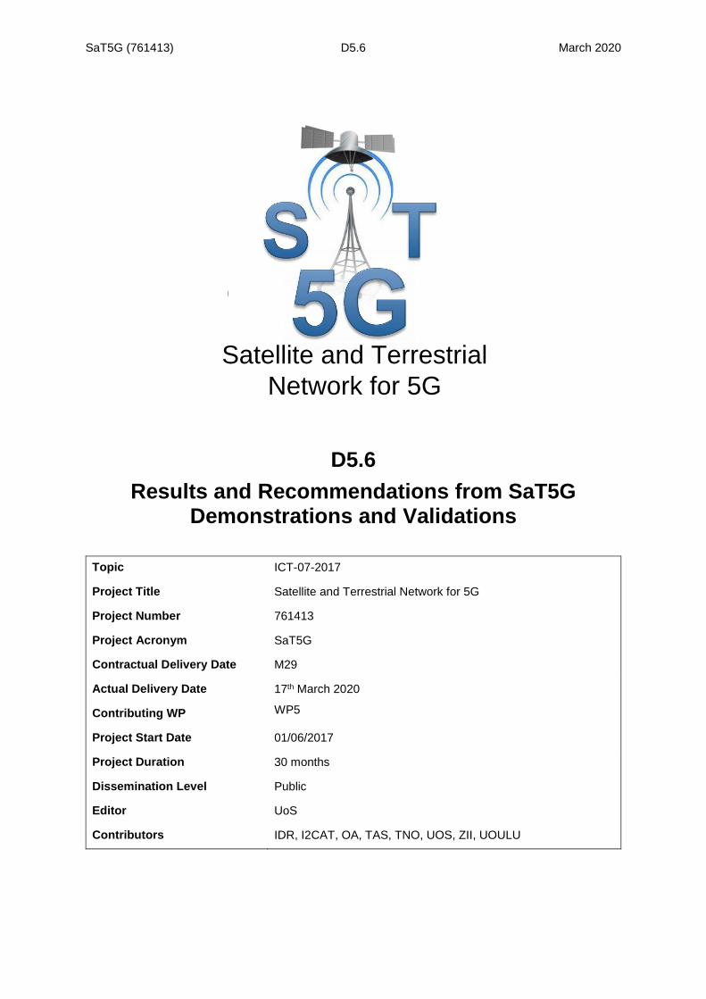
3.1.3.2 MPQUIC demonstration The second demonstration highlights how the Multi-Path version of the QUIC protocol is also a possibility to transport traffic over a 5G hybrid backhaul. In this scenario, a UE with an MPQUIC stack is connected to an MPQUIC server, cf. Figure 3-6.
Figure 3-6 Logical diagram of the Ekinops multilinking with GTPu support proxy scheme
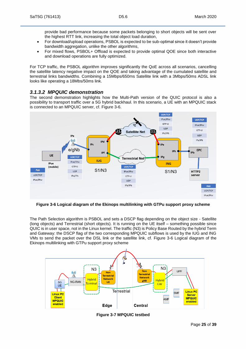
The Path Selection algorithm is PSBOL and sets a DSCP flag depending on the object size - Satellite (long objects) and Terrestrial (short objects). It is running on the UE itself – something possible since QUIC is in user space, not in the Linux kernel. The traffic (N3) is Policy Base Routed by the hybrid Term and Gateway: the DSCP flag of the two corresponding MPQUIC subflows is used by the IUG and ING VMs to send the packet over the DSL link or the satellite link, cf. Figure 3-6 Logical diagram of the Ekinops multilinking with GTPu support proxy scheme
Figure 3-7 MPQUIC testbed

SaT5G (761413) D5.6 March 2020
Page 26 of 39
The test method consists in executing a set of load cases in various network setups, using on each topology various application traffic loads. In three different setups described in Table 3-7, different scenarii are considered, with the links respecting a 5 to 1 bandwidths ratio and relatively low to be easy to produce and interpret.
Table 3-7 MPQUIC setups
Setup Link description
Terrestrial 10Mbps DSL link with a 20ms latency
Satellite 50Mbps satellite link with 600ms latency
Hybrid The above two links
The load cases described in Table 3-8 are representative of a client retrieving data from the server using the MPQUIC protocol. Each of case sends objects either in parallel mode, across multiple sessions, or in sequential mode. Mix1 and Mix2 are statistically representative of the top ten worldwide web home pages and are characterized by a great number of short and medium objects and few large objects.
Table 3-8 MPQUIC Scenarios
Scenario Traffic description
1 40KB object 8 times, i.e. 40KBx8, in sequential mode
2 40KB object 8 times in parallel mode
3 286KB object 8 times in sequential mode
4 286KB object 8 times in parallel mode
5 4MB object ,8 times in sequential mode
6 4MB object ,8 times in parallel mode
7 64MB ,3 times in sequential mode
8 64MB ,3 times in parallel mode
9 Mix1: 10KBx28 + 15KBx6 + 250KBx2+ 400KBx3+ 700KBx2 in parallel
10 Mix2: 1.5KBx46 + 5KBx15+ 15KBx32+ 250KBx2+ 400KBx3+ 700KBx1 in parallel.
The obtained results in seconds for the various test cases are summarized in Table 3-9. The values represent the total elapsed times to achieve the download. OLT is Object Load Time and PLT is Page Load Time, a page containing multiple objects. The times include the session(s) setup. The lower values in Green are optimal.
Table 3-9 MPQUIC experimental results

SaT5G (761413) D5.6 March 2020
Page 27 of 39
Times in Yellow and Red are the worse user Quality of Experience (QoE) results obtained, Green is the better.
Similar to MPTCP results, the QoE observed on the DSL link are better than the ones obtained via the satellite link for short objects (cases 1, 2, 3 and 4 as well as for the mixed traffic Mix1 and Mix2). When using a satellite link, the results are bad due to the high latency (600ms) that is not in line with the 5G delays expectations. In multi-link operations, PSBOL combined with WRR scheduler provides the same optimum performance level as ADSL alone while WRR provide bad results in sequential mode. All these results are in line with the expectations and confirm short objects are better suited to low delay links. It is also demonstrated that in multi-link operation, optimal performance is achieved when using the path selection algorithm that considers the size of the transmitted objects in order to send all the packets of a short object on the lowest RTT link.
For cases where long objects are involved (cases 5 to 8), better performances are observed, as expected, on high bandwidth links even if the delays are high. In multi-link operations PSBOL combined with WRR, and WRR provide the same optimal performance, which is better than the one provided by each link used alone. Again, these results are in line with the expectations and confirm long objects are better suited on high bandwidth links. It is also demonstrated that in multi-link operation, optimal performance is achieved when using the path selection algorithm that considers the size of the transmitted object in order to send all the packets of a long object on each of the links in WRR mode.
In Sequential mode, the page load time of a page of N objects is, as expected, nearly N*Object Load Time because the objects are loaded one after one introducing one RTT delay between objects.
3.1.3.3 Video streaming via 5G multi-linking The block diagram of the video layering over multi-linking algorithm is in Figure 2-7. The experimental results on the 5GIC testbed are below in for three different movies, Big Bug Bunny (BBB), Elephant Dream (ED) and Tear of Steel (TOS). The segment size (SD) varies from 2 to 8 seconds, and it can be seen that in general the longer the segment the higher is the start-up time but the lower is the rebuffering percentage. The enhancement layer (EL) is a measure of quality delivered and is consistent among the three movies and the three segment lengths.

SaT5G (761413) D5.6 March 2020
Page 28 of 39
Figure 3-8. Results of video layering over satellite
The percentage of video traffic offloaded to satellite is shown in Figure 3-9. It begins at zero for start-up over the lower latency terrestrial path, then climbs over time as more is buffered at the MEC. It is noted that the shorter segment times are worse than the longer times, because of the RTT for segment acknowledgement.
Figure 3-9. Offload percentage onto satellite
The same kind of effect is noted on both MPQUIC and on video layering, that if a web page or movie is broken into shorter objects or segments, the user will experience longer delays over satellite if the latency is higher than terrestrial links. Therefore, mechanisms should be further pursued that steer shorter objects or segments over shorter delay paths. The same is not necessarily true of MPTCP if split TCP-PEPs are used.
3.2 ZII testbed The test bed architecture and results for both MEO and GEO satellite backhaul demonstrations that are reproduced hereinafter are extracted from the specific ZII test bed deliverable D5.2/D5.43. As mentioned already, the MEO link was over the air, while the GEO link was emulated. It is worth to emphasize that, in both test bed demonstrations, the resource coordinator Talent was used as a single OSS layer to instantiate network services properly instructing the OSM orchestrator and OpenStack cloud controller.
3.2.1 MEO satellite link The MEO backhaul test bed developed by the ZII test bed is shown in Figure 3-10. Moreover, some of the trial results for the MEO satellite link connectivity is shown in Figure 3-11 to Figure 3-18. To the best of our knowledge, the MEO Booster technology was tried for the first time on this project, and its purpose is to manage the satellite handovers so that only one modem is needed at each end of the satellite path. This is an innovative demonstration that was delivered over-the-air for an end-to-end connectivity system for passengers to a ground data network such as the Internet.
3 D5.2 / D5.4, Demonstration of Mobile Backhaul Scenario Including Caching & Multicast. Available from
https://www.sat5g-project.eu/public-deliverables/

SaT5G (761413) D5.6 March 2020
Page 29 of 39
Figure 3-10. MEO satellite connectivity
The data rate, delay jitter and packet loss for the end to end system are shown in the following figures.
Figure 3-11 Data rate Aircraft to Datacentre
Figure 3-12. Delay jitter Aircraft to Datacentre

SaT5G (761413) D5.6 March 2020
Page 30 of 39
Figure 3-13. Packet loss Aircraft to Datacentre
Figure 3-14. Data rate Datacentre to Aircraft
Figure 3-15. Delay jitter Datacentre to Aircraft
The packet loss from Datacentre to Aircraft was nearly measured at zero. More insights can be found in D5.2 / D5.4. The overall O3b link round trip time as measured is shown in Figure 3-16 below.
Figure 3-16. End to end round trip time

SaT5G (761413) D5.6 March 2020
Page 31 of 39
The data downlink and uplink times experienced by the passenger UEs connected via 5G RAN are shown respectively in Figure 3-17 and Figure 3-18 below.
Figure 3-17. Passenger UE downlink data rate via 5G small cell
Figure 3-18. Passenger UE uplink data rate via 5G small cell
3.2.2 GEO satellite The connectivity system of the GEO satellite is shown in Figure 3-19. Note that the satellite link was emulated, it was done at RF and used Gilat SkyEdge II-c system that is virtualised in the upper layers and the Capricorn Pro VSAT. The SkyEdge II-c hub was virtualised and fully managed by the Talent OSS layer, including the creation of the Layer 2 service and the configuration of the virtualised hub components. For this demonstration, Israel and Germany were connected through a site-to-site Layer 3 VPN connection to backhaul the mock-up aircraft cabin over satellite.

SaT5G (761413) D5.6 March 2020
Page 32 of 39
Figure 3-19. Connectivity of GEO satellite link
The end-to-end data rate, delay jitter and round-trip time are shown in Figure 3-20 to Figure 3-22.
Figure 3-20. End to end GEO datarate
Figure 3-21. End to end GEO delay jitter

SaT5G (761413) D5.6 March 2020
Page 33 of 39
Figure 3-22. Round trip time of GEO
The latency between the users and the cached content in the MEC is shown in Figure 3-23.
Figure 3-23. Latency to MEC content
3.2.3 Multicast performance measurements Table 3-10 shows the results of time measurements for loading aircraft cache with 30 hours of popular content and gives an estimate of the time savings if 100 planes can be serviced at the same time using multicast.
Table 3-10. Multicast results
Parameter Unit Result
Transponder rate Mbps 60
VSAT Capacity Output Mbps 60
Nb. Popular Hours HD hours 30
Bitrate HD Mbps 6,3
Time required to Stream per plane minutes 189,00
Number of Planes NB 100,00
Time required to stream in unicast to All minutes 18900,00

SaT5G (761413) D5.6 March 2020
Page 34 of 39
3.2.4 Virtualised Services Creation Time Since the ZII test bed is a cloud infrastructure in which the services of interest were virtualised, we measured the time required to create them. In this case, we consider that the service creation time includes: 1) time to spin up the VMs from TALENT, 2) the additional time for a specific software solution to become operative and 3) the resulting service creation time. Figure 3-24 to Figure 3-27 show the measured time for each of the services created in MEO or GEO demonstrations.
Figure 3-24: Measured time durations of the different phases that are required to fully start the SkyEdge II-c satellite hub for GEO connectivity
Figure 3-25: Measured time durations of the different phases that are required to enable end-to-end connectivity over GEO satellite

SaT5G (761413) D5.6 March 2020
Page 35 of 39
Figure 3-26: Measured time durations of the different phases that are required to start the Broadpeak content delivery service
Figure 3-27: Measured service creation for the Open5GCore: one VM for the Aircraft UPF and one VM for the Ground UPF and control plane functions.
3.2.5 Control Plane Measurements The connection of the small cell radio access to the 5G core, the UEs that connect to small cells and the aircraft UPF were not affected by the O3b satellite backhaul, as shown in Table 3-11. Times were measured based on Wireshark traces considering Non-Access Stratum (NAS) messages.
Table 3-11. Cell connection times and UE attach times are not affected by satellite backhaul
Small cell connection time UE attach time
Terrestrial backhaul ~1.05 seconds ~0.74 seconds
Satellite backhaul Negligible impact compared to terrestrial
Negligible impact compared to terrestrial
In case of the GEO demonstration instead is was noticed a time to connect a UE nearly seven times larger than what measured over terrestrial backhaul. Moreover, the MEC side of the core deployed on-board the mock-up aircraft experienced a significant attach latency to the core on ground, which required adaptation of specific timers to avoid timeouts.

SaT5G (761413) D5.6 March 2020
Page 36 of 39
3.3 Oulu testbed The Oulu testbed demonstrated some aspects of the NR MAC layer over satellite, including modified RACH procedures and timing advance to cope with large cell sizes.
Table 3-12. Terrestrial results
Terrestrial
Parameter
Uplink N_RB 50 25 10
RSSI [dBm] -80.4 -80.8 -80.8
rsrp [dBm] -101.8 -102.6 -102.64
Transmission mode 1 1 1
Path loss PL 95 95 95
CQI 10 10 10
Qm 2 2 2
Downlink N_PRB 100 100 100
I_TBS Uplink 10 10 10
I_TBS Downlink 9 9 9
TBS downlink=17568 15840 15840 15840
TBS uplink=8760 8760 4392 1736
Measurements
Downlink [Mbps] 12.1 12.1 12.1
Uplink [Mbps] 4.82 3.52 1.12
Theoretical maximum
Downplink [Mbps] 17.568 17.568 17.568
Uplink [Mbps] 8.760 4.392 1.736
(=TBS*1000)
Table 3-13. Satellite results
Satellite
Parameter
Uplink N_RB 50 25 10
RSSI [dBm] -81.6 -81.4 -81.7
rsrp [dBm] -104.4 -103.8 -104.9
Transmission mode 1 1 1
Path loss PL 96 96 96
CQI 10 10 10
Qm 2 2 2
Downlink N_PRB 100 100 100
I_TBS Uplink 10 10 10
I_TBS Downlink 9 9 9
TBS downlink=17568 15840 15840 15840
TBS uplink=8760 8760 4392 1736

SaT5G (761413) D5.6 March 2020
Page 37 of 39
Satellite
Measurements
Downlink [Mbps] 11.84 11.84 11.84
Uplink [Mbps] 4.24 3.18 0.98
Theoretical maximum
Downplink [Mbps] 17.568 17.568 17.568
Uplink [Mbps] 8.760 4.392 1.736
(=TBS*1000)
Since the uplink RACH process was modified, the uplink capacity (the number of resource blocks) was changed in order to see if modified RACH has higher impact at lower available bandwidth. The maximum channel bandwidth with the used USRP is 20 MHz, equivalent to 100 resource blocks. That was used in the downlink. In the uplink, 50, 25 or 10 resource blocks were allocated to the UE/NTN terminal. The results for the terrestrial case are shown in Table 3-12 and in the satellite case in Table 3-13. The uplink throughput difference between the terrestrial case and the satellite are small. The satellite uplink throughput is 88%, 90% and 88% of that of the terrestrial one for the 50, 25 and 10 resource blocks, respectively. Obviously, the available uplink bandwidth does not affect the results. One reason for the throughput reduction in the satellite case is due to fact that more resources are reserved for the random access process that has frequent reserved slots in the frame structure. Another, more significant reason is that also HARQ process is affected by long satellite delay.
3.4 TNO testbed
The result is added value of caching in the network edge, through additions of UPF and DANE clients on MEC node. The focus was upon implementing demo and showing difference in quality of streamed video – with and without use of DANE client. It showed added value of placing DANE in MEC, and that collocating it with UPF can add benefits to satellite providing streaming content, in the case of tight integration of 5G and satellites.

SaT5G (761413) D5.6 March 2020
Page 38 of 39
4 Analysis and recommendations
4.1 Analysis of results
SaT5G is the first project to demonstrate 5G over satellite over its testbeds. This was recognised in the press following the successful industry demo day in November 2019. ISP news reported ‘SaT5G Project Finally Demonstrates 5G Data over Satellite 4.
Satellite has been proven viable for extending backhaul to moving or fixed 5G cells within a 3GPP trusted network, using SaT5G developed 3GPP integration into satellite links (e.g. NTN gNB and NTN UE). Steps have been taken to integrate at the management plane through orchestration / co-ordination functions, so that end to end service slices are set up automatically.
The testbeds and demonstrations have enabled SaT5G to become a landmark satellite 5G project which has influenced 3GPP to open up studies on NTN in Rel 16 onwards and influenced satellite operators and equipment vendors to engage in 3GPP as well as the whole area of 5G via satellite.
The testbeds have pulled through basic research into prototypes and enabled satellite equipment venders to design their equipment along 3GPP 5G standard lines to be compatible with future networks and allow integration of satellites with 5G terrestrial systems. The prototypes within Sat5G were the first that these companies had developed.
5G use cases involving backhaul, multicast and caching and multilinking involving edge MEC were successfully integrated into a 5G infrastructure in the testbeds and demonstrated over satellite, in some cases right out to 5G UE’s in small cells.
Satellite has been proven viable for moving content to the edge using multicast to MEC caches. Satellite has also proven viable for providing parallel paths to terrestrial paths to enhance broadband connection to premises for delivery of services such as MPQUIC and video. The delivery of MPQUIC over satellite is a novelty with this project.
We have used both MEO and GEO satellites in this project, and use of MEO with Booster technology to carry 5G data traffic is another example of going beyond the state of the art.
The time taken to set up various service slices over satellite was measured, using a resource co-ordinator (Talent) to trigger the deployment of core network VNFs, satellite specific VNFs and satellite links to set up end to end service slices for video and Internet access for aeroplane passengers. In this way, the project has demonstrated plug and play, since MNOs with OSS / MANO interface can automatically instantiate and configure a satellite segment in end to end slices. It is the first time such automation has been practically demonstrated in this overall context.
4.2 Recommendations for further work
The testbeds gave proof of concept demonstrations and involved few actual users. These and other applications can be extended to wider user field trials in which the test bed infrastructure can be used. The testbeds built by SaT5G are an important asset and if possible should be preserved to enable them to be used in such future trials.
SaT5G used OSM / OpenStack for the most part, laying the foundations for satellite specific VNFs and their deployment and management, and future work would be to consider migrating to ONAP / Kubernetes because of their superior scaling / carrier grade ability. Mobile and satellite operators are actively looking to these methods.
SaT5G took steps to enable SNOs to work with a 5G core network, with satellite elements presenting themselves as 3GPP elements. Within the project, we were able to demonstrate a 5G core network instantiating and configuring a satellite link via an API between the core and the satellite network management system, from a service co-ordinator that operates northbound of the orchestrator level.
4 https://www.ispreview.co.uk/index.php/2019/11/sat5g-project-finally-demonstrates-5g-data-over-satellite.html

SaT5G (761413) D5.6 March 2020
Page 39 of 39
Further work would be to develop further integration at the orchestrator level to enable instantiation of a satellite link as part of an end to end slice.
The work on integration of the satellite elements into the 5G network was sufficient for the demonstrations to take place but there were some aspects that were not possible to do within the timescale of the project. Full E2E network slicing was not possible and is clearly a topic for future work. Although some elementary QoS mapping across the satellite and terrestrial domains was accomplished this needs to be improved on. The provision of 5G network security has only been touched on by this project and needs to be further researched and implemented in future work. Thus follow on projects on the actual integration will be needed.
With direct access from UE to satellite, we interpret this as 5G NR over the satellite. This was not a feature of SaT5G although we have investigated MAC layer aspects of its implementation and taken simulation into an emulation to demonstrate changes in the numerology. This area is now a major topic in 3GPP Rel 17 and 18 and of wide interest in the community. Within SaT5G it was not possible to emulate the full 5G protocol stack for a UE connection. Follow on projects need to address this to have a full emulation of NR incorporating the satellite and ground station equipment parameters—in other words a full lab demo prior to demo’s over the satellite itself.
Finally we note that in SaT5G we have studied and demonstrated 5G over GEO and MEO satellites but have not considered constellations of LEO satellites that are now nearing their first generation implementation (OneWeb, SpaceX etc). These systems in vLEO orbits are more targeted to 5G applications due to their lower latency. The backhaul application could be considered as a logical extension of the work in SaT5G and demonstrations of this would be reasonably easy. Perhaps of more interest is the direct to terminal connections as at least one company is currently demonstrating this in 4G. As the second generation of the LEO constellations will include more processing on board it could be possible to include some 5G features also to really integrate at the satellite as well as the ground segment. We would recommend that this be the topic of future projects.