santa rosa county olf-x phase ii airfield addendum 002
TRANSCRIPT
Santa Rosa County OLF-X Phase II – Airfield Addendum 002
Escambia County, Florida
Section 32 01 19 Page 1
SECTION 32 01 19
FIELD MOLDED SEALANTS FOR SEALING JOINTS IN RIGID PAVEMENTS
PART 1 GENERAL
1.1 REFERENCES
The publications listed below form a part of this specification to the
extent referenced. The publications are referred to within the text by the
basic designation only.
ASTM INTERNATIONAL (ASTM)
ASTM C1016 (2014) Standard Test Method for Determination
of Water Absorption of Sealant Backing (Joint
Filler) Material
ASTM D5893/D5893M (2016) Standard Specification for Cold
Applied, Single Component, Chemically Curing
Silicone Joint Sealant for Portland Cement
Concrete Pavements
ASTM D6690 (2015) Standard Specification for Joint and
Crack Sealants, Hot Applied, for Concrete and
Asphalt Pavements
ASTM D789 (2015) Determination of Relative Viscosity
and Moisture Content of Polyamide (PA)
U.S. ARMY CORPS OF ENGINEERS (USACE)
COE CRD-C 525 (1989) Corps of Engineers Test Method for
Evaluation of Hot-Applied Joint Sealants for
Bubbling Due to Heating
U.S. GENERAL SERVICES ADMINISTRATION (GSA)
FS SS-S-200 (Rev E; Am 1; Notice 1) Sealant, Joint, Two-
Component, Jet-Blast-Resistant, Cold-Applied,
for Portland Cement Concrete Pavement
1.2 SUBMITTALS
Owner approval is required for submittals with a "G" designation; submittals
not having a "G" designation are for information only. When used, a
designation following the "G" designation identifies the office that will
review the submittal for the Owner. Submit the following in accordance with
Section 01 33 00 SUBMITTAL PROCEDURES:
SD-03 Product Data
Manufacturer's Recommendations; G.
Equipment.

Santa Rosa County OLF-X Phase II – Airfield Addendum 002
Escambia County, Florida
Section 32 01 19 Page 2
SD-04 Samples
Materials; G.
SD-06 Test Reports
Certified Copies of the Test Reports; G.
1.3 QUALITY ASSURANCE
1.3.1 Test Requirements
Test the joint sealant and backup or separating material for conformance
with the referenced applicable material specification. Perform testing of
the materials in an approved independent laboratory and submit certified
copies of the test reports for approval 5 days prior to the use of the
materials at the job site. Samples will be retained by the Owner for
possible future testing should the materials appear defective during or
after application. Conformance with the requirements of the laboratory
tests specified will not constitute final acceptance of the materials.
Final acceptance will be based on the performance of the in-place materials.
Submit samples of the materials (sealant, primer if required, and backup
material), in sufficient quantity for testing and approval 15 days prior to
the beginning of work. No material will be allowed to be used until it has
been approved.
1.3.2 Trial Joint Sealant Installation
Prior to the cleaning and sealing of the joints for the entire project,
prepare a test section at least 200 feet long using the specified materials
and approved equipment, so as to demonstrate the proposed joint preparation
and sealing of all types of joints in the project. Following the completion
of the test section and before any other joint is sealed, inspect the test
section to determine that the materials and installation meet the
requirements specified. If it is determined that the materials or
installation do not meet the requirements, remove the materials, and reclean
and reseal the joints at no cost to the Owner. When the test section meets
the requirements, it may be incorporated into the permanent work and paid
for at the contract unit price per linear foot for sealing items scheduled.
Prepare and seal all other joints in the manner approved for sealing the
test section.
1.4 DELIVERY, STORAGE, AND HANDLING
Inspect materials delivered to the job site for defects, unload, and store
them with a minimum of handling to avoid damage. Provide storage facilities
at the job site for maintaining materials at the temperatures and conditions
recommended by the manufacturer.
1.5 ENVIRONMENTAL REQUIREMENTS
The ambient air temperature and the pavement temperature within the joint
wall shall be a minimum of 50 degrees F and rising at the time of
application of the materials. Do not apply sealant if moisture is observed
in the joint.
Santa Rosa County OLF-X Phase II – Airfield Addendum 002
Escambia County, Florida
Section 32 01 19 Page 3
PART 2 PRODUCTS
2.1 SEALANTS
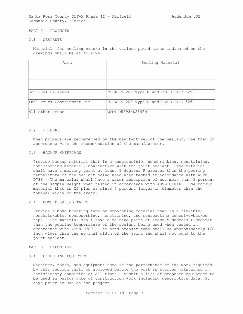
Materials for sealing cracks in the various paved areas indicated on the
drawings shall be as follows:
Area Sealing Material
Hot Fuel Helipads FS SS-S-200 Type M and COE CRD-C 525
Fuel Truck Containment Pit FS SS-S-200 Type H and COE CRD-C 525
All other areas ASTM D5893/D5893M
2.2 PRIMERS
When primers are recommended by the manufacturer of the sealant, use them in
accordance with the recommendation of the manufacturer.
2.3 BACKUP MATERIALS
Provide backup material that is a compressible, nonshrinking, nonstaining,
nonabsorbing material, nonreactive with the joint sealant. The material
shall have a melting point at least 5 degrees F greater than the pouring
temperature of the sealant being used when tested in accordance with ASTM
D789. The material shall have a water absorption of not more than 5 percent
of the sample weight when tested in accordance with ASTM C1016. Use backup
material that is 25 plus or minus 5 percent larger in diameter than the
nominal width of the crack.
2.4 BOND BREAKING TAPES
Provide a bond breaking tape or separating material that is a flexible,
nonshrinkable, nonabsorbing, nonstaining, and nonreacting adhesive-backed
tape. The material shall have a melting point at least 5 degrees F greater
than the pouring temperature of the sealant being used when tested in
accordance with ASTM D789. The bond breaker tape shall be approximately 1/8
inch wider than the nominal width of the joint and shall not bond to the
joint sealant.
PART 3 EXECUTION
3.1 EXECUTING EQUIPMENT
Machines, tools, and equipment used in the performance of the work required
by this section shall be approved before the work is started maintained in
satisfactory condition at all times. Submit a list of proposed equipment to
be used in performance of construction work including descriptive data, 30
days prior to use on the project.
Santa Rosa County OLF-X Phase II – Airfield Addendum 002
Escambia County, Florida
Section 32 01 19 Page 4
3.1.1 Joint Cleaning Equipment
3.1.1.1 Tractor-Mounted Routing Tool
Provide a routing tool, used for removing old sealant from the joints, of
such shape and dimensions and so mounted on the tractor that it will not
damage the sides of the joints. The tool shall be designed so that it can
be adjusted to remove the old material to varying depths as required. The
use of V-shaped tools or rotary impact routing devices will not be
permitted. Hand-operated spindle routing devices may be used to clean and
enlarge random cracks.
3.1.1.2 Concrete Saw
Provide a self-propelled power saw, with water-cooled diamond or abrasive
saw blades, for cutting joints to the depths and widths specified or for
refacing joints or cleaning sawed joints where sandblasting does not provide
a clean joint.
3.1.1.3 Sandblasting Equipment
Include with the sandblasting equipment an air compressor, hose, and long-
wearing venturi-type nozzle of proper size, shape and opening. The maximum
nozzle opening should not exceed 1/4 inch. The air compressor shall be
portable and capable of furnishing not less than 150 cfm and maintaining a
line pressure of not less than 90 psi at the nozzle while in use.
Demonstrate compressor capability, under job conditions, before approval.
The compressor shall be equipped with traps that will maintain the
compressed air free of oil and water. The nozzle shall have an adjustable
guide that will hold the nozzle aligned with the joint approximately 1 inch
above the pavement surface. Adjust the height, angle of inclination and the
size of the nozzle as necessary to secure satisfactory results.
3.1.1.4 Waterblasting Equipment
Include with the waterblasting equipment a trailer-mounted water tank,
pumps, high-pressure hose, wand with safety release cutoff control, nozzle,
and auxiliary water resupply equipment. Provide water tank and auxiliary
resupply equipment of sufficient capacity to permit continuous operations.
The nozzle shall have an adjustable guide that will hold the nozzle aligned
with the joint approximately 1 inch above the pavement surface. Adjust the
height, angle of inclination and the size of the nozzle as necessary to
obtain satisfactory results. A pressure gauge mounted at the pump shall
show at all times the pressure in psi at which the equipment is operating.
3.1.1.5 Hand Tools
Hand tools may be used, when approved, for removing defective sealant from a
crack and repairing or cleaning the crack faces.
3.1.2 Sealing Equipment
3.1.2.1 Two-Component, Cold-Applied, Machine Mix Sealing Equipment
Provide equipment used for proportioning, mixing, and installing FS SS-S-200
Type M joint sealants designed to deliver two semifluid components through
Santa Rosa County OLF-X Phase II – Airfield Addendum 002
Escambia County, Florida
Section 32 01 19 Page 5
hoses to a portable mixer at a preset ratio of 1 to 1 by volume using pumps
with an accuracy of plus or minus 5 percent for the quantity of each
component. The reservoir for each component shall be equipped with
mechanical agitation devices that will maintain the components in a uniform
condition without entrapping air. Incorporate provisions to permit
thermostatically controlled indirect heating of the components, when
required. However, immediately prior to proportioning and mixing, the
temperature of either component shall not exceed 90 degrees F. Provide
screens near the top of each reservoir to remove any foreign particles or
partially polymerized material that could clog fluid lines or otherwise
cause misproportioning or improper mixing of the two components. Provide
equipment capable of thoroughly mixing the two components through a range of
application rates of 10 to 60 gallons per hour and through a range of
application pressures from 50 to 1500 psi as required by material, climatic,
or operating conditions. Design the mixer for the easy removal of the
supply lines for cleaning and proportioning of the components. The mixing
head shall accommodate nozzles of different types and sizes as may be
required by various operations. The dimensions of the nozzle shall be such
that the nozzle tip will extend into the joint to allow sealing from the
bottom of the joint to the top. Maintain the initially approved equipment
in good working condition, serviced in accordance with the supplier's
instructions, and unaltered in any way without obtaining prior approval.
3.1.2.2 Two-Component, Cold-Applied, Hand-Mix Sealing Equipment
Mixing equipment for FS SS-S-200 Type H sealants shall consist of a slow-
speed electric drill or air-driven mixer with a stirrer in accordance with
the manufacturer's recommendations. Submit printed copies of manufacturer's
recommendations, 30 days prior to use on the project, where installation
procedures, or any part thereof, are required to be in accordance with those
recommendations. Installation of the material will not be allowed until the
recommendations are received. Failure to furnish these recommendations can
be cause for rejection of the material.
3.1.2.3 Cold-Applied, Single-Component Sealing Equipment
The equipment for installing ASTM D5893/D5893M single component joint
sealants shall consist of an extrusion pump, air compressor, following
plate, hoses, and nozzle for transferring the sealant from the storage
container into the joint opening. The dimension of the nozzle shall be such
that the tip of the nozzle will extend into the joint to allow sealing from
the bottom of the joint to the top. Maintain the initially approved
equipment in good working condition, serviced in accordance with the
supplier's instructions, and unaltered in any way without obtaining prior
approval. Small hand-held air-powered equipment (i.e., caulking guns) may
be used for small applications.
3.2 SAFETY
Do not place joint sealant within 25 feet of any liquid oxygen (LOX)
equipment, LOX storage, or LOX piping. Thoroughly clean joints in this area
and leave them unsealed.
3.3 PREPARATION OF JOINTS
Immediately before the installation of the sealant, thoroughly clean the
joints to remove all laitance, curing compound, filler, protrusions of

Santa Rosa County OLF-X Phase II – Airfield Addendum 002
Escambia County, Florida
Section 32 01 19 Page 6
hardened concrete, and old sealant from the sides and upper edges of the
joint space to be sealed.
3.3.1 Sawing
3.3.1.1 Facing of Joints
Accomplish facing of joints using a concrete saw as specified in paragraph
EQUIPMENT to saw through sawed and filler-type joints to loosen and remove
material until the joint is clean and open to the full specified width and
depth. Stiffen the blade with a sufficient number of suitable dummy (used)
blades or washers. Thoroughly clean, immediately following the sawing
operation, the joint opening using a water jet to remove all saw cuttings
and debris.
3.3.2 Sandblasting
The newly exposed concrete joint faces and the pavement surfaces extending a
minimum of 1/2 inch from the joint edges shall be waterblasted clean. use
a multiple-pass technique until the surfaces are free of dust, dirt, curing
compound, filler, old sealant residue, or any foreign debris that might
prevent the bonding of the sealant to the concrete. After final cleaning
and immediately prior to sealing, blow out the joints with compressed air
and leave them completely free of debris and water.
3.3.3 Back-Up Material
When the joint opening is of a greater depth than indicated for the sealant
depth, plug or seal off the lower portion of the joint opening using a back-
up material to prevent the entrance of the sealant below the specified
depth. Take care to ensure that the backup material is placed at the
specified depth and is not stretched or twisted during installation.
3.3.4 Bond Breaking Tape
Where inserts or filler materials contain bitumen, or the depth of the joint
opening does not allow for the use of a backup material, insert a bond
breaker separating tape to prevent incompatibility with the filler materials
and three-sided adhesion of the sealant. Securely bond the tape to the
bottom of the joint opening so it will not float up into the new sealant.
3.3.5 Rate of Progress of Joint Preparation
Limit the stages of joint preparation, which include sandblasting, air
pressure cleaning and placing of the back-up material to only that lineal
footage that can be sealed during the same day.
3.4 PREPARATION OF SEALANT
3.4.1 Hot-Poured Sealants
Do not heat sealants conforming to ASTM D6690 in excess of the safe heating
temperature recommended by the manufacturer as shown on the sealant
containers. Withdraw and waste sealant that has been overheated or
subjected to application temperatures for over 4 hours or that has remained
in the applicator at the end of the day's operation.
Santa Rosa County OLF-X Phase II – Airfield Addendum 002
Escambia County, Florida
Section 32 01 19 Page 7
3.4.2 Type M Sealants
Inspect the FS SS-S-200 Type M sealant components and containers prior to
use. Reject any materials that contain water, hard caking of any separated
constituents, nonreversible jell, or materials that are otherwise
unsatisfactory. Settlement of constituents in a soft mass that can be
readily and uniformly remixed in the field with simple tools will not be
cause for rejection. Prior to transfer of the components from the shipping
containers to the appropriate reservoir of the application equipment,
thoroughly mix the materials to ensure homogeneity of the components and
incorporation of all constituents at the time of transfer. When necessary
for remixing prior to transfer to the application equipment reservoirs, warm
the components to a temperature not to exceed 90 degrees F by placing the
components in heated storage or by other approved methods but in no case
shall the components be heated by direct flame, or in a single walled
kettle, or a kettle without an oil bath.
3.4.3 Type H Sealants
Mix the FS SS-S-200 Type H sealant components either in the container
furnished by the manufacturer or a cylindrical metal container of volume
approximately 50 percent greater than the package volume. Thoroughly mix
the base material in accordance with the manufacturer's instructions. The
cure component shall then be slowly added during continued mixing until a
uniform consistency is obtained.
3.4.4 Single-Component, Cold-Applied Sealants
Inspect the ASTM D5893/D5893M sealant and containers prior to use. Reject
any materials that contain water, hard caking of any separated constituents,
nonreversible jell, or materials that are otherwise unsatisfactory.
Settlement of constituents in a soft mass that can be readily and uniformly
remixed in the field with simple tools will not be cause for rejection.
3.5 INSTALLATION OF SEALANT
3.5.1 Time of Application
Seal joints immediately following final cleaning of the joint walls and
following the placement of the separating or backup material. Open joints,
that cannot be sealed under the conditions specified, or when rain
interrupts sealing operations shall be recleaned and allowed to dry prior to
installing the sealant.
3.5.2 Sealing Joints
Immediately preceding, but not more than 50 feet ahead of the joint sealing
operations, perform a final cleaning with compressed air. Fill the joints
from the bottom up to 1/8 inch plus or minus 1/16 inch below the pavement
surface. Remove and discard excess or spilled sealant from the pavement by
approved methods. Install the sealant in such a manner as to prevent the
formation of voids and entrapped air. In no case shall gravity methods or
pouring pots be used to install the sealant material. Traffic shall not be
permitted over newly sealed pavement until authorized by the Owner's
Representative. When a primer is recommended by the manufacturer, apply it
evenly to the joint faces in accordance with the manufacturer's
instructions. Check the joints frequently to ensure that the newly

Santa Rosa County OLF-X Phase II – Airfield Addendum 002
Escambia County, Florida
Section 32 01 19 Page 8
installed sealant is cured to a tack-free condition within the time
specified.
3.6 INSPECTION
3.6.1 Joint Cleaning
Inspect joints during the cleaning process to correct improper equipment and
cleaning techniques that damage the concrete pavement in any manner.
Cleaned joints will be approved prior to installation of the separating or
back-up material and joint sealant.
3.6.2 Joint Sealant Application Equipment
Inspect the application equipment to ensure conformance to temperature
requirements, proper proportioning and mixing (if two-component sealant) and
proper installation. Evidences of bubbling, improper installation, failure
to cure or set will be cause to suspend operations until causes of the
deficiencies are determined and corrected.
3.6.3 Joint Sealant
Inspect the joint sealant for proper rate of cure and set, bonding to the
joint walls, cohesive separation within the sealant, reversion to liquid,
entrapped air and voids. Sealants exhibiting any of these deficiencies at
any time prior to the final acceptance of the project shall be removed from
the joint, wasted, and replaced as specified herein at no additional cost to
the Owner.
3.7 CLEAN-UP
Upon completion of the project, remove all unused materials from the site
and leave the pavement in a clean condition.
-- End of Section --
Santa Rosa County OLF-X Phase II – Airfield Addendum 002
Escambia County, Florida
Section 32 11 20 Page 1
SECTION 32 11 20
BASE COURSE FOR RIGID PAVING
PART 1 GENERAL
1.1 UNIT PRICES
1.1.1 Measurement
1.1.1.1 Area
Measure the quantity of 6 inch thick rigid pavement base course completed
and accepted, as determined by the Owner's Representative, in square yards.
1.1.2 Payment
1.1.2.1 Course Material
Quantities of rigid pavement base course, determined as specified above,
will be paid for at the respective contract unit prices, which will
constitute full compensation for the construction and completion of the
rigid pavement base course.
1.1.2.2 Stabilization
Cohesionless subgrade or select subbase courses to be stabilized, as
specified in paragraph PREPARATION OF UNDERLYING COURSE OR SUBGRADE, will be
paid for as a special item on a tonnage basis including extra manipulation
as required.
1.1.3 Waybills and Delivery Tickets
Submit copies of waybills and delivery tickets during progress of the work.
Before the final payment is allowed, file certified waybills and certified
delivery tickets for all aggregates actually used.
1.2 REFERENCES
The publications listed below form a part of this specification to the
extent referenced. The publications are referred to within the text by the
basic designation only.
AMERICAN ASSOCIATION OF STATE HIGHWAY AND TRANSPORTATION OFFICIALS
(AASHTO)
AASHTO T 180 (2017) Standard Method of Test for Moisture-
Density Relations of Soils Using a 4.54-kg
(10-lb) Rammer and a 457-mm (18-in.) Drop
AASHTO T 224 (2010) Standard Method of Test for Correction
for Coarse Particles in the Soil Compaction
Test
Santa Rosa County OLF-X Phase II – Airfield Addendum 002
Escambia County, Florida
Section 32 11 20 Page 2
ASTM INTERNATIONAL (ASTM)
ASTM C117 (2017) Standard Test Method for Materials
Finer than 75-um (No. 200) Sieve in Mineral
Aggregates by Washing
ASTM C131/C131M (2014) Standard Test Method for Resistance to
Degradation of Small-Size Coarse Aggregate by
Abrasion and Impact in the Los Angeles
Machine
ASTM C136/C136M (2014) Standard Test Method for Sieve
Analysis of Fine and Coarse Aggregates
ASTM C29/C29M (2017a) Standard Test Method for Bulk Density
("Unit Weight") and Voids in Aggregate
ASTM D1556/D1556M (2015; E 2016) Standard Test Method for
Density and Unit Weight of Soil in Place by
Sand-Cone Method
ASTM D1557 (2012; E 2015) Standard Test Methods for
Laboratory Compaction Characteristics of Soil
Using Modified Effort (56,000 ft-lbf/ft3)
(2700 kN-m/m3)
ASTM D2167 (2015) Density and Unit Weight of Soil in
Place by the Rubber Balloon Method
ASTM D2487 (2011) Soils for Engineering Purposes
(Unified Soil Classification System)
ASTM D4318 (2017) Standard Test Methods for Liquid
Limit, Plastic Limit, and Plasticity Index of
Soils
ASTM D6938 (2017) Standard Test Method for In-Place
Density and Water Content of Soil and Soil-
Aggregate by Nuclear Methods (Shallow Depth)
ASTM D75/D75M (2014) Standard Practice for Sampling
Aggregates
ASTM E11 (2016) Standard Specification for Woven Wire
Test Sieve Cloth and Test Sieves
1.3 DEGREE OF COMPACTION
Degree of compaction required, except as noted in the second sentence, is
expressed as a percentage of the maximum laboratory dry density obtained by
the test procedure presented in ASTM D1557 abbreviated as a percent of
laboratory maximum dry density. Since ASTM D1557 applies only to soils that
have 30 percent or less by weight of their particles retained on the 3/4
inch sieve, the degree of compaction for material having more than 30
percent by weight of their particles retained on the 3/4 inch sieve will be
expressed as a percentage of the laboratory maximum dry density in
accordance with AASHTO T 180 Method D and corrected with AASHTO T 224.

Santa Rosa County OLF-X Phase II – Airfield Addendum 002
Escambia County, Florida
Section 32 11 20 Page 3
1.4 SUBMITTALS
Owner approval is required for submittals with a "G" designation; submittals
not having a "G" designation are for information only. Submit the following
in accordance with Section 01 33 00 SUBMITTAL PROCEDURES:
SD-03 Product Data
Plant, Equipment, and Tools; G
Waybills and Delivery Tickets
SD-06 Test Reports
Initial Tests; G
In-Place Tests; G
1.5 EQUIPMENT, TOOLS, AND MACHINES
All plant, equipment, and tools used in the performance of the work will be
subject to approval by the Owner's Representative before the work is
started. Maintain all plant, equipment, and tools in satisfactory working
condition at all times. Submit a list of proposed equipment, including
descriptive data. Use equipment capable of minimizing segregation,
producing the required compaction, meeting grade controls, thickness
control, and smoothness requirements as set forth herein.
1.6 QUALITY ASSURANCE
Sampling and testing are the responsibility of the Contractor. Perform
sampling and testing using a laboratory approved in accordance with Section
01 45 00.00 20 QUALITY CONTROL. Work requiring testing will not be
permitted until the testing laboratory has been inspected and approved.
Test the materials to establish compliance with the specified requirements
and perform testing at the specified frequency. The Owner's Representative
may specify the time and location of the tests. Furnish copies of test
results to the Owner's Representative within 24 hours of completion of the
tests.
1.6.1 Sampling
Take samples for laboratory testing in conformance with ASTM D75/D75M. When
deemed necessary, the sampling will be observed by the Owner's
Representative.
1.6.2 Tests
1.6.2.1 Sieve Analysis
Perform sieve analysis in conformance with ASTM C117 and ASTM C136/C136M
using sieves conforming to ASTM E11.
1.6.2.2 Liquid Limit and Plasticity Index
Determine liquid limit and plasticity index in accordance with ASTM D4318.
Santa Rosa County OLF-X Phase II – Airfield Addendum 002
Escambia County, Florida
Section 32 11 20 Page 4
1.6.2.3 Moisture-Density Determinations
Determine the laboratory maximum dry density and optimum moisture in
accordance with paragraph DEGREE OF COMPACTION.
1.6.2.4 Field Density Tests
Measure field density in accordance with ASTM D1556/D1556M, ASTM D2167, or
ASTM D6938. For the method presented in ASTM D1556/D1556M, use the base
plate, as shown in the drawing. For the method presented in ASTM D6938,
check the calibration curves and adjust them, if necessary, using only the
sand cone method as described in paragraph Calibration, of the ASTM
publication. Tests performed in accordance with ASTM D6938 result in a wet
unit weight of soil and ASTM D6938 will be used to determine the moisture
content of the soil. Also check the calibration curves furnished with the
moisture gauges along with density calibration checks as described in ASTM
D6938. Make the calibration checks of both the density and moisture gauges
using the prepared containers of material method, as described in paragraph
Calibration, in ASTM D6938, on each different type of material to be tested
at the beginning of a job and at intervals as directed. Submit calibration
curves and related test results prior to using the device or equipment being
calibrated.
1.6.2.5 Wear Test
Perform wear tests on rigid pavement base course material in conformance
with ASTM C131/C131M.
1.6.2.6 Weight of Slag
Determine weight per cubic foot of slag in accordance with ASTM C29/C29M.
1.7 ENVIRONMENTAL REQUIREMENTS
Perform construction when the atmospheric temperature is above 35 degrees F.
When the temperature falls below 35 degrees F, protect all completed areas
by approved methods against detrimental effects of freezing. Correct
completed areas damaged by freezing, rainfall, or other weather conditions
to meet specified requirements.
PART 2 PRODUCTS
2.1 MATERIALS
2.1.1 Rigid Pavement Base Course
Provide aggregates consisting of crushed stone or slag, gravel, shell, sand,
or other sound, durable, approved materials processed and blended or
naturally combined. Provide aggregates which are durable and sound, free
from lumps and balls of clay, organic matter, objectionable coatings, and
other foreign material. The percentage of loss of material retained on the
No. 4 sieve must not exceed 50 percent after 500 revolutions when tested in
accordance with ASTM C131/C131M. At least 50 percent by weight retained on
each sieve must have one freshly fractured face with the area at least equal
Santa Rosa County OLF-X Phase II – Airfield Addendum 002
Escambia County, Florida
Section 32 11 20 Page 5
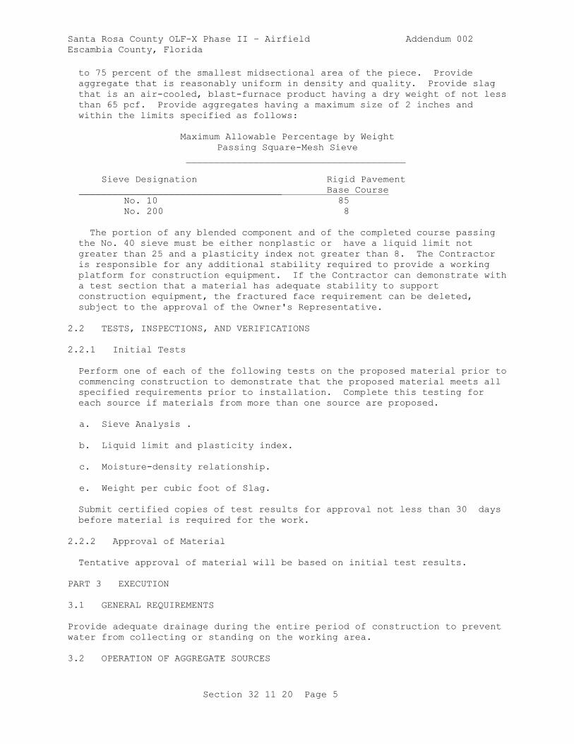
to 75 percent of the smallest midsectional area of the piece. Provide
aggregate that is reasonably uniform in density and quality. Provide slag
that is an air-cooled, blast-furnace product having a dry weight of not less
than 65 pcf. Provide aggregates having a maximum size of 2 inches and
within the limits specified as follows:
Maximum Allowable Percentage by Weight
Passing Square-Mesh Sieve
_______________________________________
Sieve Designation Rigid Pavement
____________________________________ Base Course
No. 10 85
No. 200 8
The portion of any blended component and of the completed course passing
the No. 40 sieve must be either nonplastic or have a liquid limit not
greater than 25 and a plasticity index not greater than 8. The Contractor
is responsible for any additional stability required to provide a working
platform for construction equipment. If the Contractor can demonstrate with
a test section that a material has adequate stability to support
construction equipment, the fractured face requirement can be deleted,
subject to the approval of the Owner's Representative.
2.2 TESTS, INSPECTIONS, AND VERIFICATIONS
2.2.1 Initial Tests
Perform one of each of the following tests on the proposed material prior to
commencing construction to demonstrate that the proposed material meets all
specified requirements prior to installation. Complete this testing for
each source if materials from more than one source are proposed.
a. Sieve Analysis .
b. Liquid limit and plasticity index.
c. Moisture-density relationship.
e. Weight per cubic foot of Slag.
Submit certified copies of test results for approval not less than 30 days
before material is required for the work.
2.2.2 Approval of Material
Tentative approval of material will be based on initial test results.
PART 3 EXECUTION
3.1 GENERAL REQUIREMENTS
Provide adequate drainage during the entire period of construction to prevent
water from collecting or standing on the working area.
3.2 OPERATION OF AGGREGATE SOURCES
Santa Rosa County OLF-X Phase II – Airfield Addendum 002
Escambia County, Florida
Section 32 11 20 Page 6
Clearing, stripping and excavating are the responsibility of the
Contractor. Condition aggregate sources on Owner property to readily drain
and leave in a satisfactory condition upon completion of the work.
3.3 STOCKPILING MATERIAL
Clear and level storage sites prior to stockpiling of material. Stockpile
all materials, including approved material available from excavation and
grading, in the manner and at the locations designated. Stockpile
aggregates on the cleared and leveled areas designated by the Owner's
Representative to prevent segregation. Stockpile materials obtained from
different sources separately.
3.4 PREPARATION OF UNDERLYING COURSE OR SUBGRADE
Clean the underlying course or subgrade of all foreign substances prior to
constructing therigid pavement base course. Do not constructrigid pavement
base course on underlying course or subgrade that is frozen. Construct the
surface of the underlying course or subgrade to meet specified compaction
and surface tolerances. Correct ruts or soft yielding spots in the
underlying courses, areas having inadequate compaction, and deviations of
the surface from the specified requirements set forth herein by loosening
and removing soft or unsatisfactory material and adding approved material,
reshaping to line and grade, and recompacting to specified density
requirements. For cohesionless underlying courses or subgrades containing
sands or gravels, as defined in ASTM D2487, stabilize the surface prior to
placement of the overlying course. Stabilize by mixing the overlying course
material into the underlying course and compacting by approved methods.
Consider the stabilized material as part of the underlying course and meet
all requirements of the underlying course. Do not allow traffic or other
operations to disturb the finished underlying course and maintain in a
satisfactory condition until the overlying course is placed.
3.5 GRADE CONTROL
Provide a finished and completed rigid pavement base course conforming to
the lines, grades, and cross sections shown. Place line and grade stakes as
necessary for control.
3.6 MIXING AND PLACING MATERIALS
Mix and place the materials to obtain uniformity of the material at the
water content specified. Make such adjustments in mixing or placing
procedures or in equipment as may be directed to obtain the true grades, to
minimize segregation and degradation, to reduce or accelerate loss or
increase of water, and to insure a satisfactory subbase course.
3.7 LAYER THICKNESS
Compact the completed course to the thickness indicated. No individual
layer may be thicker than 6 inches nor be thinner than 3 inches in compacted
thickness. Compact the course(s) to a total thickness that is within 1/2
inch of the thickness indicated. Where the measured thickness is more than
1/2 inch deficient, correct such areas by scarifying, adding new material of
proper gradation, reblading, and recompacting as directed. Where the
measured thickness is more than 1/2 inch thicker than indicated, the course
will be considered as conforming to the specified thickness requirements.
Santa Rosa County OLF-X Phase II – Airfield Addendum 002
Escambia County, Florida
Section 32 11 20 Page 7
The average job thickness will be the average of all thickness measurements
taken for the job and must be within 1/4 inch of the thickness indicated.
Measure the total thickness of the course(s) at intervals of one measurement
for each 500 square yards of completed course. Measure total thickness
using 3 inch diameter test holes penetrating the completed course.
3.8 COMPACTION
Compact each layer of the material, as specified, with approved compaction
equipment. Maintain water content during the compaction procedure to within
plus or minus 2 percent of optimum water content determined from laboratory
tests as specified in this Section. Begin rolling at the outside edge of
the surface and proceed to the center, overlapping on successive trips at
least one-half the width of the roller. Slightly vary the length of
alternate trips of the roller. Adjust speed of the roller as needed so that
displacement of the aggregate does not occur. Compact mixture with hand-
operated power tampers in all places not accessible to the rollers.
Continue compaction of the rigid base course until each layer is compacted
through the full depth to the percent of laboratory maximum density shown in
the Contract plans. Make such adjustments in compacting or finishing
procedures as may be directed by the Owner's Representative to obtain true
grades, to minimize segregation and degradation, to reduce or increase water
content, and to ensure a satisfactoryrigid pavement base course. Remove any
materials that are found to be unsatisfactory and replace with satisfactory
material or rework, as directed, to meet the requirements of this
specification.
3.9 EDGES OF RIGID PAVEMENT BASE COURSE
Place approved material along the outer edges of the rigid pavement base
course in sufficient quantity to compact to the thickness of the course
being constructed. When the course is being constructed in two or more
layers, simultaneously roll and compact at least a 2 foot width of this
shoulder material with the rolling and compacting of each layer of the rigid
pavement base course, as directed.
3.10 FINISHING
Finish the surface of the top layer of rigid pavement base course after
final compaction by cutting any overbuild to grade and rolling with a steel-
wheeled roller. Do not add thin layers of material to the top layer of
rigid pavement base course to meet grade. If the elevation of the top layer
of rigid pavement base course is 1/2 inch or more below grade, scarify the
top layer to a depth of at least 3 inches and blend new material in and
compact to bring to grade. Make adjustments to rolling and finishing
procedures as directed by the Owner's Representative to minimize segregation
and degradation, obtain grades, maintain moisture content, and insure an
acceptable rigid pavement base course. Should the surface become rough,
corrugated, uneven in texture, or traffic marked prior to completion,
scarify the unsatisfactory portion and rework and recompact it or replace as
directed.
3.11 SMOOTHNESS TEST
Construct the top layer so that the surface shows no deviations in excess of
3/8 inch when tested with a 12 foot straightedge. Take measurements in
successive positions parallel to the centerline of the area to be paved.
Santa Rosa County OLF-X Phase II – Airfield Addendum 002
Escambia County, Florida
Section 32 11 20 Page 8
Also take measurements perpendicular to the centerline at 50 foot intervals.
Correct deviations exceeding this amount by removing material and replacing
with new material, or by reworking existing material and compacting it to
meet these specifications.
3.12 FIELD QUALITY CONTROL
3.12.1 In-Place Tests
Perform one of each of the following tests on samples taken from the placed
and compacted rigid pavement base course. Take samples and test at the
rates indicated.
a. Perform density tests on every lift of material placed and at a
frequency of one set of tests for every 250 square yards, or portion
thereof, of completed area.
b. Perform sieve analysis on every lift of material placed and at a
frequency of one sieve analysis for every 1,000 square yards, or
portion thereof, of material placed.
c. Perform liquid limit and plasticity index tests at the same frequency
as the sieve analysis.
d. Measure the thickness of each course at intervals providing at least
one measurement for each 500 square yards or part thereof. Measure
the thickness using test holes, at least 3 inches in diameter through
the course.
3.12.2 Approval of Material
Final approval of the materials will be based on tests for gradation, liquid
limit, and plasticity index performed on samples taken from the completed
and fully compacted course(s).
3.13 TRAFFIC
Do not allow traffic on the completed rigid pavement base course.
3.14 MAINTENANCE
Maintain the completed course in a satisfactory condition until the full
pavement section is completed and accepted. Immediately repair any defects
and repeat repairs as often as necessary to keep the area intact. Retest
any course that was not paved over prior to the onset of winter to verify
that it still complies with the requirements of this specification. Rework
or replace any area that is damaged as necessary to comply with this
specification.
3.15 DISPOSAL OF UNSATISFACTORY MATERIALS
Dispose of any unsuitable materials that have been removed as directed . No
additional payments will be made for materials that have to be replaced.
-- End of Section --

Santa Rosa County OLF-X Phase II – Airfield Addendum 002
Escambia County, Florida
Section 32 11 23 Page 1
SECTION 32 11 23
AGGREGATE BASE COURSES
PART 1 GENERAL
1.1 UNIT PRICES
1.1.1 Measurement
1.1.1.1 Area
Measure the quantity of ABC completed and accepted to the thickness as
shown in the Contract plans, as determined by the Owner's Representative, in
square yards.
1.1.2 Payment
1.1.2.1 Base Course Material
Quantities of ABC, determined as specified above, will be paid for at the
respective contract unit prices, which will constitute full compensation for
the construction and completion of the ABC.
1.1.2.2 Stabilization
Cohesionless subgrade or subbase courses to be stabilized, as specified in
paragraph PREPARATION OF UNDERLYING COURSE OR SUBGRADE, will be paid for as
a special item on a tonnage basis including extra manipulation as required.
1.1.3 Waybills and Delivery Tickets
Submit copies of waybills and delivery tickets during progress of the work.
Before the final payment is allowed, file certified waybills and certified
delivery tickets for all aggregates actually used.
1.2 REFERENCES
The publications listed below form a part of this specification to the
extent referenced. The publications are referred to in the text by basic
designation only.
AMERICAN ASSOCIATION OF STATE HIGHWAY AND TRANSPORTATION OFFICIALS
(AASHTO)
AASHTO T 180 (2017) Standard Method of Test for Moisture-
Density Relations of Soils Using a 4.54-kg
(10-lb) Rammer and a 457-mm (18-in.) Drop
AASHTO T 224 (2010) Standard Method of Test for Correction
for Coarse Particles in the Soil Compaction
Test
Santa Rosa County OLF-X Phase II – Airfield Addendum 002
Escambia County, Florida
Section 32 11 23 Page 2
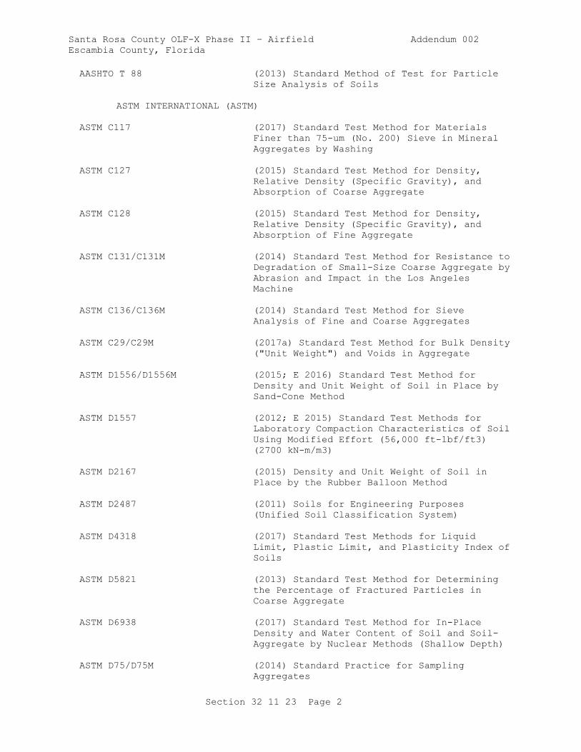
AASHTO T 88 (2013) Standard Method of Test for Particle
Size Analysis of Soils
ASTM INTERNATIONAL (ASTM)
ASTM C117 (2017) Standard Test Method for Materials
Finer than 75-um (No. 200) Sieve in Mineral
Aggregates by Washing
ASTM C127 (2015) Standard Test Method for Density,
Relative Density (Specific Gravity), and
Absorption of Coarse Aggregate
ASTM C128 (2015) Standard Test Method for Density,
Relative Density (Specific Gravity), and
Absorption of Fine Aggregate
ASTM C131/C131M (2014) Standard Test Method for Resistance to
Degradation of Small-Size Coarse Aggregate by
Abrasion and Impact in the Los Angeles
Machine
ASTM C136/C136M (2014) Standard Test Method for Sieve
Analysis of Fine and Coarse Aggregates
ASTM C29/C29M (2017a) Standard Test Method for Bulk Density
("Unit Weight") and Voids in Aggregate
ASTM D1556/D1556M (2015; E 2016) Standard Test Method for
Density and Unit Weight of Soil in Place by
Sand-Cone Method
ASTM D1557 (2012; E 2015) Standard Test Methods for
Laboratory Compaction Characteristics of Soil
Using Modified Effort (56,000 ft-lbf/ft3)
(2700 kN-m/m3)
ASTM D2167 (2015) Density and Unit Weight of Soil in
Place by the Rubber Balloon Method
ASTM D2487 (2011) Soils for Engineering Purposes
(Unified Soil Classification System)
ASTM D4318 (2017) Standard Test Methods for Liquid
Limit, Plastic Limit, and Plasticity Index of
Soils
ASTM D5821 (2013) Standard Test Method for Determining
the Percentage of Fractured Particles in
Coarse Aggregate
ASTM D6938 (2017) Standard Test Method for In-Place
Density and Water Content of Soil and Soil-
Aggregate by Nuclear Methods (Shallow Depth)
ASTM D75/D75M (2014) Standard Practice for Sampling
Aggregates
Santa Rosa County OLF-X Phase II – Airfield Addendum 002
Escambia County, Florida
Section 32 11 23 Page 3
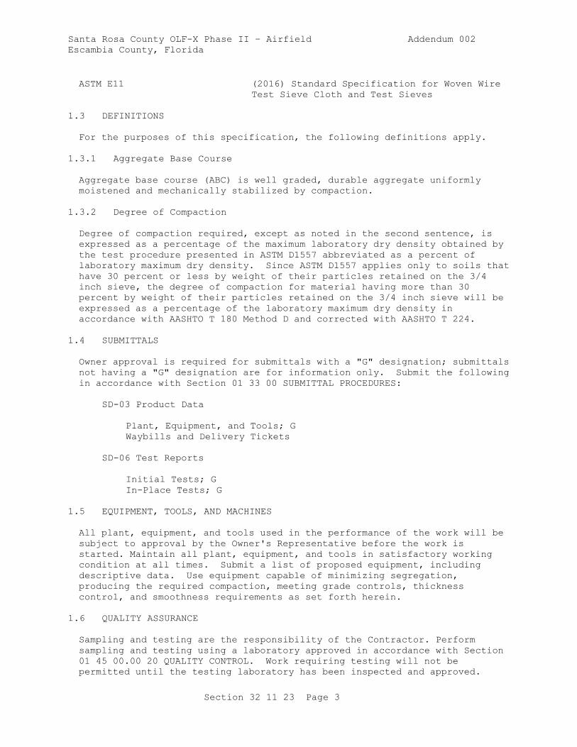
ASTM E11 (2016) Standard Specification for Woven Wire
Test Sieve Cloth and Test Sieves
1.3 DEFINITIONS
For the purposes of this specification, the following definitions apply.
1.3.1 Aggregate Base Course
Aggregate base course (ABC) is well graded, durable aggregate uniformly
moistened and mechanically stabilized by compaction.
1.3.2 Degree of Compaction
Degree of compaction required, except as noted in the second sentence, is
expressed as a percentage of the maximum laboratory dry density obtained by
the test procedure presented in ASTM D1557 abbreviated as a percent of
laboratory maximum dry density. Since ASTM D1557 applies only to soils that
have 30 percent or less by weight of their particles retained on the 3/4
inch sieve, the degree of compaction for material having more than 30
percent by weight of their particles retained on the 3/4 inch sieve will be
expressed as a percentage of the laboratory maximum dry density in
accordance with AASHTO T 180 Method D and corrected with AASHTO T 224.
1.4 SUBMITTALS
Owner approval is required for submittals with a "G" designation; submittals
not having a "G" designation are for information only. Submit the following
in accordance with Section 01 33 00 SUBMITTAL PROCEDURES:
SD-03 Product Data
Plant, Equipment, and Tools; G
Waybills and Delivery Tickets
SD-06 Test Reports
Initial Tests; G
In-Place Tests; G
1.5 EQUIPMENT, TOOLS, AND MACHINES
All plant, equipment, and tools used in the performance of the work will be
subject to approval by the Owner's Representative before the work is
started. Maintain all plant, equipment, and tools in satisfactory working
condition at all times. Submit a list of proposed equipment, including
descriptive data. Use equipment capable of minimizing segregation,
producing the required compaction, meeting grade controls, thickness
control, and smoothness requirements as set forth herein.
1.6 QUALITY ASSURANCE
Sampling and testing are the responsibility of the Contractor. Perform
sampling and testing using a laboratory approved in accordance with Section
01 45 00.00 20 QUALITY CONTROL. Work requiring testing will not be
permitted until the testing laboratory has been inspected and approved.

Santa Rosa County OLF-X Phase II – Airfield Addendum 002
Escambia County, Florida
Section 32 11 23 Page 4
Test the materials to establish compliance with the specified requirements
and perform testing at the specified frequency. The Owner's Representative
may specify the time and location of the tests. Furnish copies of test
results to the Owner's Representative within 24 hours of completion of the
tests.
1.6.1 Sampling
Take samples for laboratory testing in conformance with ASTM D75/D75M. When
deemed necessary, the sampling will be observed by the Owner's
Representative.
1.6.2 Tests
1.6.2.1 Sieve Analysis
Perform sieve analysis in conformance with ASTM C117 and ASTM C136/C136M
using sieves conforming to ASTM E11. .
1.6.2.2 Liquid Limit and Plasticity Index
Determine liquid limit and plasticity index in accordance with ASTM D4318.
1.6.2.3 Moisture-Density Determinations
Determine the laboratory maximum dry density and optimum moisture content in
accordance with paragraph DEGREE OF COMPACTION.
1.6.2.4 Field Density Tests
Measure field density in accordance with ASTM D1556/D1556M, ASTM D2167 or
ASTM D6938. For the method presented in ASTM D1556/D1556M use the base
plate as shown in the drawing. For the method presented in ASTM D6938 check
the calibration curves and adjust them, if necessary, using only the sand
cone method as described in paragraph Calibration, of the ASTM publication.
Tests performed in accordance with ASTM D6938 result in a wet unit weight of
soil and ASTM D6938 will be used to determine the moisture content of the
soil. Also check the calibration curves furnished with the moisture gauges
along with density calibration checks as described in ASTM D6938. Make the
calibration checks of both the density and moisture gauges using the
prepared containers of material method, as described in paragraph
Calibration of ASTM D6938, on each different type of material being tested
at the beginning of a job and at intervals as directed. Submit calibration
curves and related test results prior to using the device or equipment being
calibrated.
1.6.2.5 Wear Test
Perform wear tests on ABC course material in conformance with ASTM
C131/C131M.
1.6.2.6 Weight of Slag
Determine weight per cubic foot of slag in accordance with ASTM C29/C29M on
the ABC course material.
Santa Rosa County OLF-X Phase II – Airfield Addendum 002
Escambia County, Florida
Section 32 11 23 Page 5
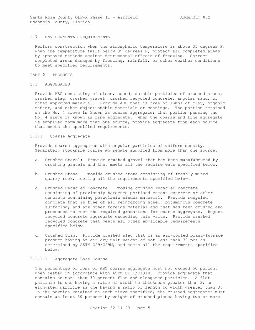
1.7 ENVIRONMENTAL REQUIREMENTS
Perform construction when the atmospheric temperature is above 35 degrees F.
When the temperature falls below 35 degrees F, protect all completed areas
by approved methods against detrimental effects of freezing. Correct
completed areas damaged by freezing, rainfall, or other weather conditions
to meet specified requirements.
PART 2 PRODUCTS
2.1 AGGREGATES
Provide ABC consisting of clean, sound, durable particles of crushed stone,
crushed slag, crushed gravel, crushed recycled concrete, angular sand, or
other approved material. Provide ABC that is free of lumps of clay, organic
matter, and other objectionable materials or coatings. The portion retained
on the No. 4 sieve is known as coarse aggregate; that portion passing the
No. 4 sieve is known as fine aggregate. When the coarse and fine aggregate
is supplied form more than one source, provide aggregate from each source
that meets the specified requirements.
2.1.1 Coarse Aggregate
Provide coarse aggregates with angular particles of uniform density.
Separately stockpile coarse aggregate supplied from more than one source.
a. Crushed Gravel: Provide crushed gravel that has been manufactured by
crushing gravels and that meets all the requirements specified below.
b. Crushed Stone: Provide crushed stone consisting of freshly mined
quarry rock, meeting all the requirements specified below.
c. Crushed Recycled Concrete: Provide crushed recycled concrete
consisting of previously hardened portland cement concrete or other
concrete containing pozzolanic binder material. Provide recycled
concrete that is free of all reinforcing steel, bituminous concrete
surfacing, and any other foreign material and that has been crushed and
processed to meet the required gradations for coarse aggregate. Reject
recycled concrete aggregate exceeding this value. Provide crushed
recycled concrete that meets all other applicable requirements
specified below.
d. Crushed Slag: Provide crushed slag that is an air-cooled blast-furnace
product having an air dry unit weight of not less than 70 pcf as
determined by ASTM C29/C29M, and meets all the requirements specified
below.
2.1.1.1 Aggregate Base Course
The percentage of loss of ABC coarse aggregate must not exceed 50 percent
when tested in accordance with ASTM C131/C131M. Provide aggregate that
contains no more than 30 percent flat and elongated particles. A flat
particle is one having a ratio of width to thickness greater than 3; an
elongated particle is one having a ratio of length to width greater than 3.
In the portion retained on each sieve specified, the crushed aggregates must
contain at least 50 percent by weight of crushed pieces having two or more
Santa Rosa County OLF-X Phase II – Airfield Addendum 002
Escambia County, Florida
Section 32 11 23 Page 6
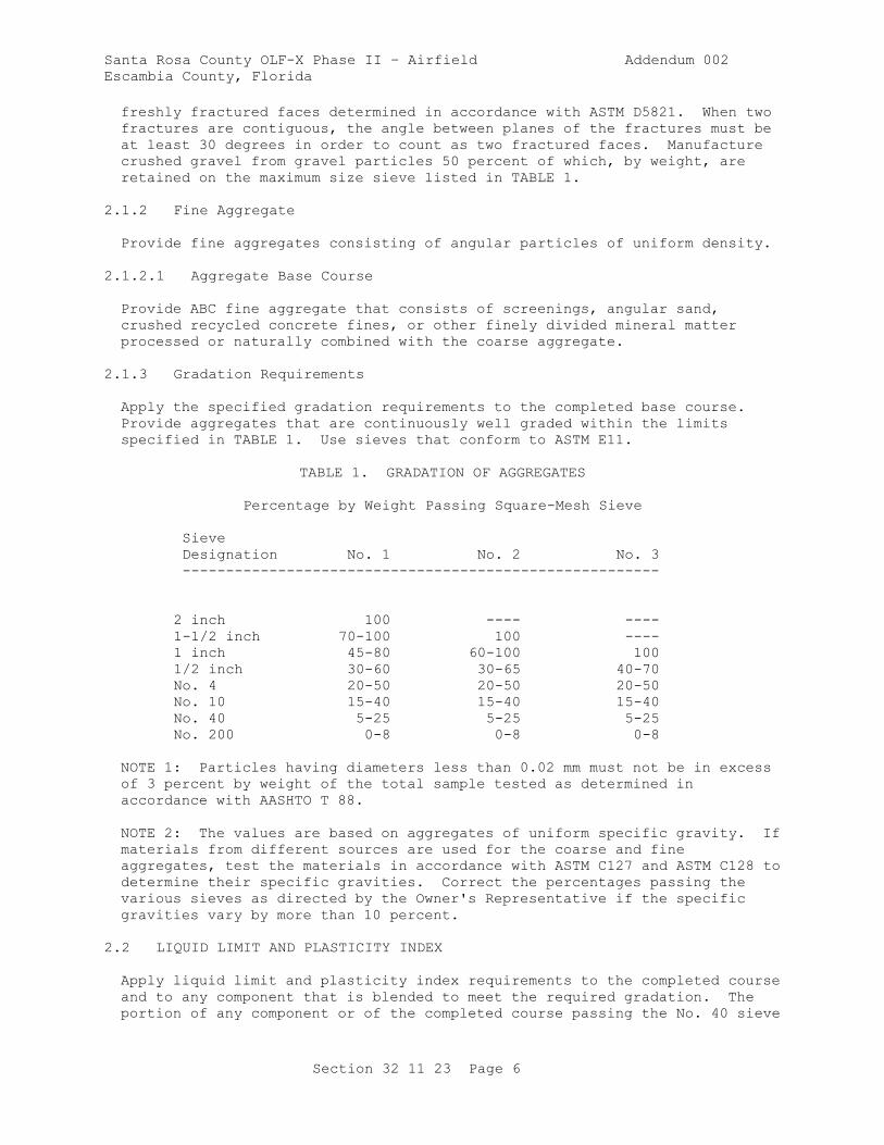
freshly fractured faces determined in accordance with ASTM D5821. When two
fractures are contiguous, the angle between planes of the fractures must be
at least 30 degrees in order to count as two fractured faces. Manufacture
crushed gravel from gravel particles 50 percent of which, by weight, are
retained on the maximum size sieve listed in TABLE 1.
2.1.2 Fine Aggregate
Provide fine aggregates consisting of angular particles of uniform density.
2.1.2.1 Aggregate Base Course
Provide ABC fine aggregate that consists of screenings, angular sand,
crushed recycled concrete fines, or other finely divided mineral matter
processed or naturally combined with the coarse aggregate.
2.1.3 Gradation Requirements
Apply the specified gradation requirements to the completed base course.
Provide aggregates that are continuously well graded within the limits
specified in TABLE 1. Use sieves that conform to ASTM E11.
TABLE 1. GRADATION OF AGGREGATES
Percentage by Weight Passing Square-Mesh Sieve
Sieve
Designation No. 1 No. 2 No. 3
-------------------------------------------------------
2 inch 100 ---- ----
1-1/2 inch 70-100 100 ----
1 inch 45-80 60-100 100
1/2 inch 30-60 30-65 40-70
No. 4 20-50 20-50 20-50
No. 10 15-40 15-40 15-40
No. 40 5-25 5-25 5-25
No. 200 0-8 0-8 0-8
NOTE 1: Particles having diameters less than 0.02 mm must not be in excess
of 3 percent by weight of the total sample tested as determined in
accordance with AASHTO T 88.
NOTE 2: The values are based on aggregates of uniform specific gravity. If
materials from different sources are used for the coarse and fine
aggregates, test the materials in accordance with ASTM C127 and ASTM C128 to
determine their specific gravities. Correct the percentages passing the
various sieves as directed by the Owner's Representative if the specific
gravities vary by more than 10 percent.
2.2 LIQUID LIMIT AND PLASTICITY INDEX
Apply liquid limit and plasticity index requirements to the completed course
and to any component that is blended to meet the required gradation. The
portion of any component or of the completed course passing the No. 40 sieve
Santa Rosa County OLF-X Phase II – Airfield Addendum 002
Escambia County, Florida
Section 32 11 23 Page 7
must be either nonplastic or have a liquid limit not greater than 25 and a
plasticity index not greater than 5.
2.3 TESTS, INSPECTIONS, AND VERIFICATIONS
2.3.1 Initial Tests
Perform one of each of the following tests, on the proposed material prior
to commencing construction, to demonstrate that the proposed material meets
all specified requirements when furnished. Complete this testing for each
source if materials from more than one source are proposed.
a. Sieve Analysis.
b. Liquid limit and plasticity index.
c. Moisture-density relationship.
d. Wear.
f. Weight per cubic foot of Slag.
g.
Submit certified copies of test results for approval not less than 30 days
before material is required for the work.
2.3.2 Approval of Material
Tentative approval of material will be based on initial test results.
PART 3 EXECUTION
3.1 GENERAL REQUIREMENTS
When the ABC is constructed in more than one layer, clean the previously
constructed layer of loose and foreign matter by sweeping with power
sweepers or power brooms, except that hand brooms may be used in areas where
power cleaning is not practicable. Provide adequate drainage during the
entire period of construction to prevent water from collecting or standing
on the working area.
3.2 OPERATION OF AGGREGATE SOURCES
Clearing, stripping, and excavating are the responsibility of the
Contractor. Condition aggregate sources on Owner property to readily drain
and leave in a satisfactory condition upon completion of the work.
3.3 STOCKPILING MATERIAL
Clear and level storage sites prior to stockpiling of material. Stockpile
all materials, including approved material available from excavation and
grading, in the manner and at the locations designated. Stockpile
aggregates on the cleared and leveled areas designated by the Owner's
Representative to prevent segregation. Stockpile materials obtained from
different sources separately.
Santa Rosa County OLF-X Phase II – Airfield Addendum 002
Escambia County, Florida
Section 32 11 23 Page 8
3.4 PREPARATION OF UNDERLYING COURSE OR SUBGRADE
Clean the underlying course or subgrade of all foreign substances prior to
constructing the base course(s). Do not construct base course(s) on
underlying course or subgrade that is frozen. Construct the surface of the
underlying course or subgrade to meet specified compaction and surface
tolerances. Correct ruts or soft yielding spots in the underlying courses,
areas having inadequate compaction, and deviations of the surface from the
specified requirements set forth herein by loosening and removing soft or
unsatisfactory material and adding approved material, reshaping to line and
grade, and recompacting to specified density requirements. For cohesionless
underlying courses or subgrades containing sands or gravels, as defined in
ASTM D2487, stabilize the surface prior to placement of the base course(s).
Stabilize by mixing ABC into the underlying course and compacting by
approved methods. Consider the stabilized material as part of the
underlying course and meet all requirements of the underlying course. Do
not allow traffic or other operations to disturb the finished underlying
course and maintain in a satisfactory condition until the base course is
placed.
3.5 GRADE CONTROL
Provide a finished and completed base course conforming to the lines,
grades, and cross sections shown. Place line and grade stakes as necessary
for control.
3.6 MIXING AND PLACING MATERIALS
Mix the coarse and fine aggregates in a stationary plant. Make adjustments
in mixing procedures or in equipment, as directed, to obtain true grades, to
minimize segregation or degradation, to obtain the required water content,
and to insure a satisfactory base course meeting all requirements of this
specification. Place the mixed material on the prepared subgrade or subbase
in layers of uniform thickness with an approved spreader. Place the layers
so that when compacted they will be true to the grades or levels required
with the least possible surface disturbance. Where the base course is
placed in more than one layer, clean the previously constructed layers of
loose and foreign matter by sweeping with power sweepers, power brooms, or
hand brooms, as directed. Make adjustments in placing procedures or
equipment as may be directed by the Owner's Representative to obtain true
grades, to minimize segregation and degradation, to adjust the water
content, and to insure an acceptable base course.
3.7 LAYER THICKNESS
Compact the completed base course to the thickness indicated. No individual
layer may be thicker than 6 inches nor be thinner than 3 inches in compacted
thickness. Compact the base course(s) to a total thickness that is within
1/2 inch of the thickness indicated. Where the measured thickness is more
than 1/2 inch deficient, correct such areas by scarifying, adding new
material of proper gradation, reblading, and recompacting as directed.
Where the measured thickness is more than 1/2 inch thicker than indicated,
the course will be considered as conforming to the specified thickness
requirements. The average job thickness will be the average of all
thickness measurements taken for the job and must be within 1/4 inch of the
thickness indicated. Measure the total thickness of the base course at
intervals of one measurement for each 500 square yards of base course.

Santa Rosa County OLF-X Phase II – Airfield Addendum 002
Escambia County, Florida
Section 32 11 23 Page 9
Measure total thickness using 3 inch diameter test holes penetrating the
base course.
3.8 COMPACTION
Compact each layer of the base course, as specified, with approved
compaction equipment. Maintain water content during the compaction
procedure to within plus or minus 2 percent of the optimum water content
determined from laboratory tests as specified in this Section. Begin
rolling at the outside edge of the surface and proceed to the center,
overlapping on successive trips at least one-half the width of the roller.
Slightly vary the length of alternate trips of the roller. Adjust speed of
the roller as needed so that displacement of the aggregate does not occur.
Compact mixture with hand-operated power tampers in all places not
accessible to the rollers. Continue compaction until each layer is
compacted through the full depth to at least 100 percent of laboratory
maximum density. Make such adjustments in compacting or finishing
procedures as may be directed by the Owner's Representative to obtain true
grades, to minimize segregation and degradation, to reduce or increase water
content, and to ensure a satisfactory base course. Remove any materials
found to be unsatisfactory and replace with satisfactory material or rework,
as directed, to meet the requirements of this specification.
3.9 EDGES OF BASE COURSE
Place the base course(s) so that the completed section will be a minimum of
6 inches wider, on all sides, than the next layer that will be placed above
it. Place approved material along the outer edges of the base course in
sufficient quantity to compact to the thickness of the course being
constructed. When the course is being constructed in two or more layers,
simultaneously roll and compact at least a 2 foot width of this shoulder
material with the rolling and compacting of each layer of the base course,
as directed.
3.10 FINISHING
Finish the surface of the top layer of base course after final compaction
by cutting any overbuild to grade and rolling with a steel-wheeled roller.
Do not add thin layers of material to the top layer of base course to meet
grade. If the elevation of the top layer of base course is 1/2 inch or more
below grade, scarify the top layer to a depth of at least 3 inches and blend
new material in and compact and proof roll to bring to grade. Make
adjustments to rolling and finishing procedures as directed by the Owner's
Representative to minimize segregation and degradation, obtain grades,
maintain moisture content, and insure an acceptable base course. Should the
surface become rough, corrugated, uneven in texture, or traffic marked prior
to completion, scarify the unsatisfactory portion and rework and recompact
it or replace as directed.
3.11 SMOOTHNESS TEST
Construct the top layer so that the surface shows no deviations in excess of
3/8 inch when tested with a 12 foot straightedge. Take measurements in
successive positions parallel to the centerline of the area to be paved.
Also take measurements perpendicular to the centerline at 50 foot intervals.
Correct deviations exceeding this amount by removing material and replacing
Santa Rosa County OLF-X Phase II – Airfield Addendum 002
Escambia County, Florida
Section 32 11 23 Page 10
with new material, or by reworking existing material and compacting it to
meet these specifications.
3.12 FIELD QUALITY CONTROL
3.12.1 In-Place Tests
Perform each of the following tests on samples taken from the placed and
compacted ABC. Take samples and test at the rates indicated. Perform
sampling and testing of recycled concrete aggregate at twice the specified
frequency until the material uniformity is established.
a. Perform density tests on every lift of material placed and at a
frequency of one set of tests for every 250 square yards, or portion
thereof, of completed area.
b. Perform sieve analysis on every lift of material placed and at a
frequency of one sieve analysis for every 500 square yards, or portion
thereof, of material placed.
c. Perform liquid limit and plasticity index tests at the same frequency
as the sieve analysis.
d. Measure the thickness of the base course at intervals providing at
least one measurement for each 500 square yards of base course or part
thereof. Measure the thickness using test holes, at least 3 inch in
diameter through the base course.
3.12.2 Approval of Material
Final approval of the materials will be based on tests for gradation, liquid
limit, and plasticity index performed on samples taken from the completed
and fully compacted course(s).
3.13 TRAFFIC
Completed portions of the base course may be opened to limited traffic,
provided there is no marring or distorting of the surface by the traffic.
Do not allow heavy equipment on the completed base course except when
necessary for construction. When it is necessary for heavy equipment to
travel on the completed base course, protect the area against marring or
damage to the completed work.
3.14 MAINTENANCE
Maintain the base course in a satisfactory condition until the full pavement
section is completed and accepted. Immediately repair any defects and
repeat repairs as often as necessary to keep the area intact. Retest any
base course that was not paved over prior to the onset of winter to verify
that it still complies with the requirements of this specification. Rework
or replace any area of base course that is damaged as necessary to comply
with this specification.
3.15 DISPOSAL OF UNSATISFACTORY MATERIALS
Dispose of any unsuitable materials that have been removed as directed. No
additional payments will be made for materials that have to be replaced.

Santa Rosa County OLF-X Phase II – Airfield Addendum 002
Escambia County, Florida
Section 32 11 23 Page 11
-- End of Section --
Santa Rosa County OLF-X Phase II – Airfield Addendum 002
Escambia County, Florida
Section 32 12 15.13 Page 1
SECTION 32 12 15.13
ASPHALT PAVING FOR AIRFIELDS
PART 1 GENERAL
1.1 FULL PAYMENT
1.1.1 Method of Measurement
The amount paid for will be the number of short tons of hot-mix asphalt
pavement mixture used in the accepted work. Hot-mix asphalt pavement
mixture shall be weighed after mixing, and no separate payment will be made
for weight of asphalt cement material incorporated herein.
1.1.2 Basis of Payment
Quantities of hot-mix asphalt pavement, determined as specified above, will
be paid for at respective contract unit prices or at reduced prices adjusted
in accordance with paragraphs PERCENT PAYMENT and QUALITY ASSURANCE.
Payment will constitute full compensation for furnishing all materials,
equipment, plant, and tools; and for all labor and other incidentals
necessary to complete work required by this section of the specification.
1.2 PERCENT PAYMENT
When a lot of material fails to meet the specification requirements for 100
percent pay as outlined in the following paragraphs, that lot shall be
removed and replaced, or accepted at a reduced price which will be computed
by multiplying the unit price by the lot's pay factor. The lot pay factor
is determined by taking the lowest computed pay factor based on either
laboratory air voids, in-place density, grade or smoothness (each discussed
below). At the end of the project, an average of all lot pay factors will
be calculated. If this average lot pay factor exceeds 95.0 percent and no
individual lot has a pay factor less than 75.0 percent, then the percent
payment for the entire project will be 100 percent of the unit bid price.
If the average lot pay factor is less than 95.0 percent, then each lot will
be paid for at the unit price multiplied by the lot's pay factor. For any
lots which are less than 2000 short tons, a weighted lot pay factor will be
used to calculate the average lot pay factor. When work on a lot is
required to be terminated before all sublots are completed, the results from
the completed sublots will be analyzed to determine the percent payment for
the lot following the same procedures and requirements for full lots but
with fewer test results.
1.2.1 Mat and Joint Densities
The average in-place mat and joint densities are expressed as a percentage
of the average theoretical maximum density (TMD) for the lot. The average
TMD for each lot will be determined as the average TMD of the four random
samples per lot. The average in-place mat density and joint density for a
lot are determined and compared with Table 1 to calculate a single pay
factor per lot based on in-place density, as described below. First, a pay
factor for both mat density and joint density are determined from Table 1.
Santa Rosa County OLF-X Phase II – Airfield Addendum 002
Escambia County, Florida
Section 32 12 15.13 Page 2
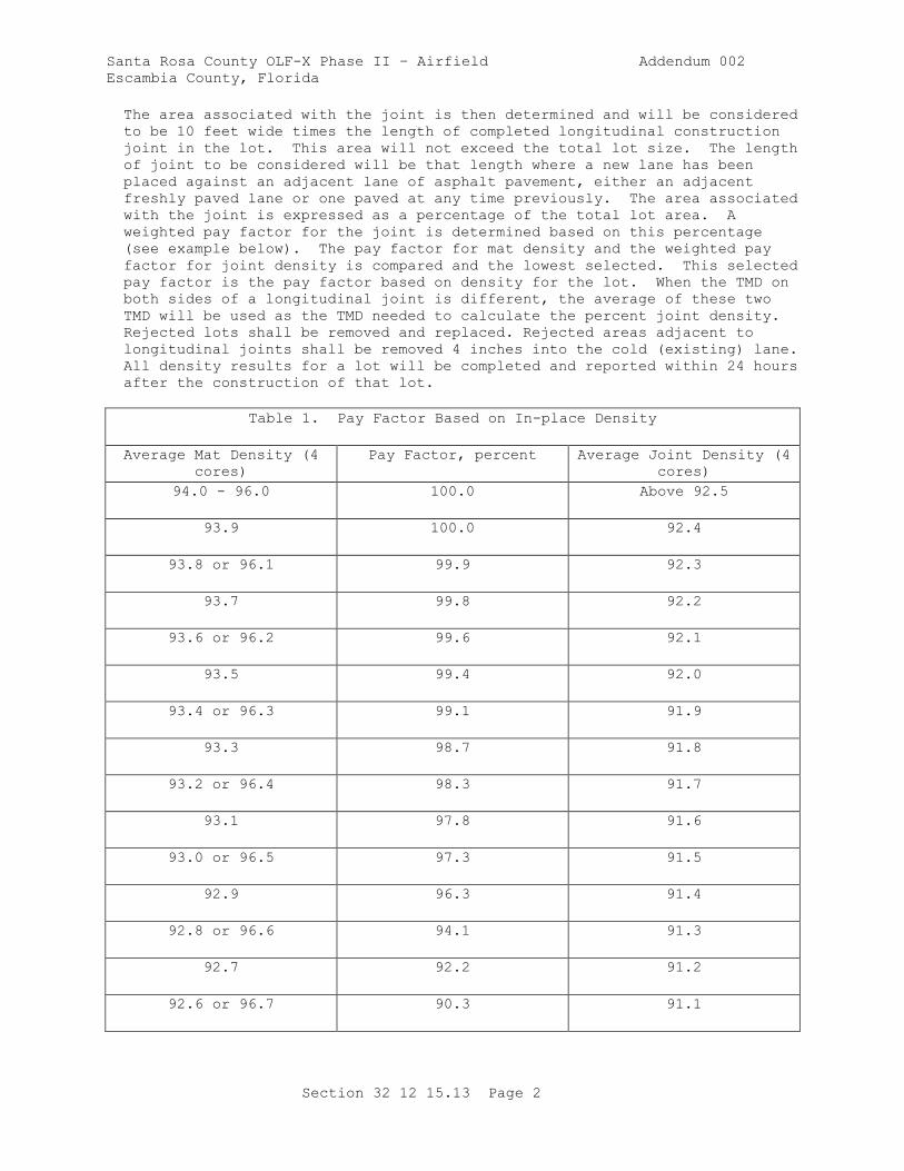
The area associated with the joint is then determined and will be considered
to be 10 feet wide times the length of completed longitudinal construction
joint in the lot. This area will not exceed the total lot size. The length
of joint to be considered will be that length where a new lane has been
placed against an adjacent lane of asphalt pavement, either an adjacent
freshly paved lane or one paved at any time previously. The area associated
with the joint is expressed as a percentage of the total lot area. A
weighted pay factor for the joint is determined based on this percentage
(see example below). The pay factor for mat density and the weighted pay
factor for joint density is compared and the lowest selected. This selected
pay factor is the pay factor based on density for the lot. When the TMD on
both sides of a longitudinal joint is different, the average of these two
TMD will be used as the TMD needed to calculate the percent joint density.
Rejected lots shall be removed and replaced. Rejected areas adjacent to
longitudinal joints shall be removed 4 inches into the cold (existing) lane.
All density results for a lot will be completed and reported within 24 hours
after the construction of that lot.
Table 1. Pay Factor Based on In-place Density
Average Mat Density (4
cores)
Pay Factor, percent Average Joint Density (4
cores)
94.0 - 96.0 100.0 Above 92.5
93.9 100.0 92.4
93.8 or 96.1 99.9 92.3
93.7 99.8 92.2
93.6 or 96.2 99.6 92.1
93.5 99.4 92.0
93.4 or 96.3 99.1 91.9
93.3 98.7 91.8
93.2 or 96.4 98.3 91.7
93.1 97.8 91.6
93.0 or 96.5 97.3 91.5
92.9 96.3 91.4
92.8 or 96.6 94.1 91.3
92.7 92.2 91.2
92.6 or 96.7 90.3 91.1
Santa Rosa County OLF-X Phase II – Airfield Addendum 002
Escambia County, Florida
Section 32 12 15.13 Page 3
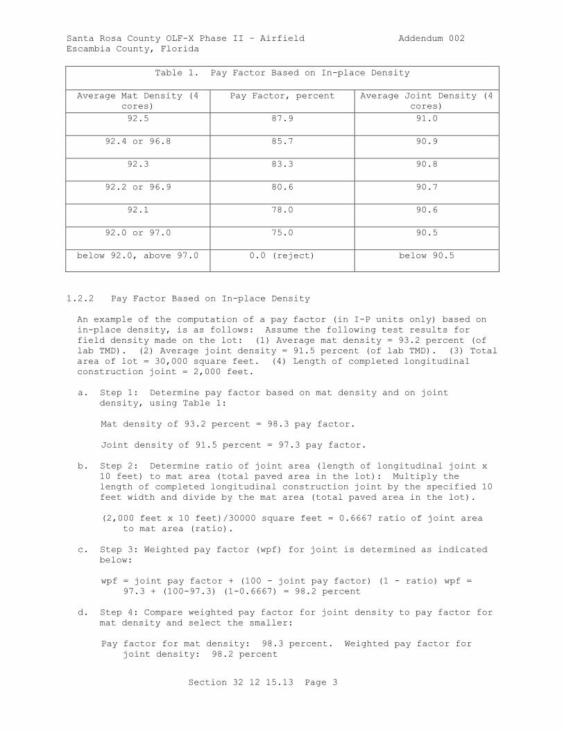
Table 1. Pay Factor Based on In-place Density
Average Mat Density (4
cores)
Pay Factor, percent Average Joint Density (4
cores)
92.5 87.9 91.0
92.4 or 96.8 85.7 90.9
92.3 83.3 90.8
92.2 or 96.9 80.6 90.7
92.1 78.0 90.6
92.0 or 97.0 75.0 90.5
below 92.0, above 97.0 0.0 (reject) below 90.5
1.2.2 Pay Factor Based on In-place Density
An example of the computation of a pay factor (in I-P units only) based on
in-place density, is as follows: Assume the following test results for
field density made on the lot: (1) Average mat density = 93.2 percent (of
lab TMD). (2) Average joint density = 91.5 percent (of lab TMD). (3) Total
area of lot = 30,000 square feet. (4) Length of completed longitudinal
construction joint = 2,000 feet.
a. Step 1: Determine pay factor based on mat density and on joint
density, using Table 1:
Mat density of 93.2 percent = 98.3 pay factor.
Joint density of 91.5 percent = 97.3 pay factor.
b. Step 2: Determine ratio of joint area (length of longitudinal joint x
10 feet) to mat area (total paved area in the lot): Multiply the
length of completed longitudinal construction joint by the specified 10
feet width and divide by the mat area (total paved area in the lot).
(2,000 feet x 10 feet)/30000 square feet = 0.6667 ratio of joint area
to mat area (ratio).
c. Step 3: Weighted pay factor (wpf) for joint is determined as indicated
below:
wpf = joint pay factor + (100 - joint pay factor) (1 - ratio) wpf =
97.3 + (100-97.3) (1-0.6667) = 98.2 percent
d. Step 4: Compare weighted pay factor for joint density to pay factor for
mat density and select the smaller:
Pay factor for mat density: 98.3 percent. Weighted pay factor for
joint density: 98.2 percent

Santa Rosa County OLF-X Phase II – Airfield Addendum 002
Escambia County, Florida
Section 32 12 15.13 Page 4
Select the smaller of the two values as pay factor based on density:
98.2 percent
1.2.3 Payment Adjustment for Smoothness (Final Wearing Surface Only)
Profilograph Testing. Record the location and data from all profilograph
measurements. When the Profile Index of a lot exceeds the tolerance
specified in paragraph SMOOTHNESS REQUIREMENTS by 1.0 inch per mile, but
less than 2.0 inches per mile, after any reduction of high spots or removal
and replacement, the computed pay factor for that lot based on surface
smoothness will be 95 percent. When the Profile Index exceeds the tolerance
by 2.0 inches per mile, but less than 3.0 inches per mile, the computed pay
factor will be 90 percent. When the Profile Index exceeds the tolerance by
3.0 inches per mile, but less than 4.0 inches per mile, the computed pay
factor will be 75 percent. Remove and replact the lot when the Profile
Index exceeds the tolerance by 4.0 inches per mile or more, at no additional
cost to the . Regardless of the above, correct any small individual area
with surface deviation which exceeds the tolerance given above by more than
5.0 inches per mile or more, by grinding to meet the specification
requirements above or remove and replace at no additional cost to the Owner.
1.2.4 Laboratory Air Voids and Theoretical Maximum Density
Laboratory air voids will be calculated in accordance with ASTM D3203/D3203M
by determining the density of each lab compacted specimen using the
laboratory-prepared, thoroughly dry method in ASTM D2726/D2726M and
determining the theoretical maximum density (TMD) of four of the sublots
using ASTM D2041/D2041M. Laboratory air void calculations for each lot will
use the average theoretical maximum density values obtained for the lot.
The mean absolute deviation of the four laboratory air void contents (one
from each sublot) from the JMF air void content will be evaluated and a pay
factor determined from Table 2. All laboratory air void tests will be
completed and reported within 24 hours after completion of construction of
each lot. The TMD is also used for computation of compaction, as required
in paragraph MAT AND JOINT DENSITIES above.
1.2.5 Mean Absolute Deviation
An example of the computation of mean absolute deviation for laboratory air
voids is as follows: Assume that the laboratory air voids are determined
from 4 random samples of a lot (where 3 specimens were compacted from each
sample). The average laboratory air voids for each sublot sample are
determined to be 3.5, 3.0, 4.0, and 3.7. Assume that the target air voids
from the JMF is 4.0. The mean absolute deviation is then:
Mean Absolute Deviation = (|3.5 - 4.0| + |3.0 - 4.0| + |4.0 - 4.0| + |3.7 -
4.0|)/4
= (0.5 + 1.0 + 0.0 + 0.3)/4 = (1.8)/4 = 0.45
The mean absolute deviation for laboratory air voids is determined to be
0.45. It can be seen from Table 2 that the lot's pay factor based on
laboratory air voids, is 100 percent.
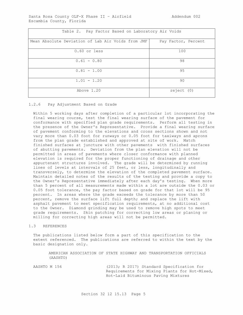
Santa Rosa County OLF-X Phase II – Airfield Addendum 002
Escambia County, Florida
Section 32 12 15.13 Page 5
Table 2. Pay Factor Based on Laboratory Air Voids
Mean Absolute Deviation of Lab Air Voids from JMF Pay Factor, Percent
O.60 or less 100
0.61 - 0.80 98
0.81 - 1.00 95
1.01 - 1.20 90
Above 1.20 reject (0)
1.2.6 Pay Adjustment Based on Grade
Within 5 working days after completion of a particular lot incorporating the
final wearing course, test the final wearing surface of the pavement for
conformance with specified plan grade requirements. Perform all testing in
the presence of the Owner's Representative. Provide a final wearing surface
of pavement conforming to the elevations and cross sections shown and not
vary more than 0.03 foot for runways or 0.05 foot for taxiways and aprons
from the plan grade established and approved at site of work. Match
finished surfaces at juncture with other pavements with finished surfaces
of abutting pavements. Deviation from the plan elevation will not be
permitted in areas of pavements where closer conformance with planned
elevation is required for the proper functioning of drainage and other
appurtenant structures involved. The grade will be determined by running
lines of levels at intervals of 25 feet, or less, longitudinally and
transversely, to determine the elevation of the completed pavement surface.
Maintain detailed notes of the results of the testing and provide a copy to
the Owner's Representative immediately after each day's testing. When more
than 5 percent of all measurements made within a lot are outside the 0.03 or
0.05 foot tolerance, the pay factor based on grade for that lot will be 95
percent. In areas where the grade exceeds the tolerance by more than 50
percent, remove the surface lift full depth; and replace the lift with
asphalt pavement to meet specification requirements, at no additional cost
to the Owner. Diamond grinding may be used to remove high spots to meet
grade requirements. Skin patching for correcting low areas or planing or
milling for correcting high areas will not be permitted.
1.3 REFERENCES
The publications listed below form a part of this specification to the
extent referenced. The publications are referred to within the text by the
basic designation only.
AMERICAN ASSOCIATION OF STATE HIGHWAY AND TRANSPORTATION OFFICIALS
(AASHTO)
AASHTO M 156 (2013; R 2017) Standard Specification for
Requirements for Mixing Plants for Hot-Mixed,
Hot-Laid Bituminous Paving Mixtures

Santa Rosa County OLF-X Phase II – Airfield Addendum 002
Escambia County, Florida
Section 32 12 15.13 Page 6
AASHTO M 320 (2017) Standard Specification for
Performance-Graded Asphalt Binder
AASHTO T 304 (2011; R 2015) Standard Method of Test for
Uncompacted Void Content of Fine Aggregate
AASHTO T 308 (2016) Standard Method of Test for
Determining the Asphalt Binder Content of Hot
Mix Asphalt (HMA) by the Ignition Method
AASHTO T 329 (2015) Standard Test Method for Moisture
Content of Hot Mix Asphalt (HMA) by Oven
Method
ASPHALT INSTITUTE (AI)
AI MS-2 (2015) Asphalt Mix Design Methods
ASTM INTERNATIONAL (ASTM)
ASTM C117 (2017) Standard Test Method for Materials
Finer than 75-um (No. 200) Sieve in Mineral
Aggregates by Washing
ASTM C127 (2015) Standard Test Method for Density,
Relative Density (Specific Gravity), and
Absorption of Coarse Aggregate
ASTM C128 (2015) Standard Test Method for Density,
Relative Density (Specific Gravity), and
Absorption of Fine Aggregate
ASTM C131/C131M (2014) Standard Test Method for Resistance to
Degradation of Small-Size Coarse Aggregate by
Abrasion and Impact in the Los Angeles
Machine
ASTM C136/C136M (2014) Standard Test Method for Sieve
Analysis of Fine and Coarse Aggregates
ASTM C142/C142M (2017) Standard Test Method for Clay Lumps
and Friable Particles in Aggregates
ASTM C29/C29M (2017a) Standard Test Method for Bulk Density
("Unit Weight") and Voids in Aggregate
ASTM C566 (2013) Standard Test Method for Total
Evaporable Moisture Content of Aggregate by
Drying
ASTM C88 (2013) Standard Test Method for Soundness of
Aggregates by Use of Sodium Sulfate or
Magnesium Sulfate
ASTM D140/D140M (2016) Standard Practice for Sampling Asphalt
Materials
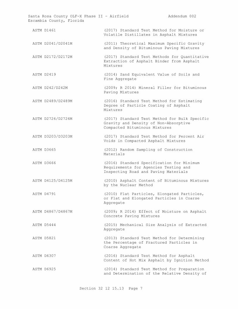
Santa Rosa County OLF-X Phase II – Airfield Addendum 002
Escambia County, Florida
Section 32 12 15.13 Page 7
ASTM D1461 (2017) Standard Test Method for Moisture or
Volatile Distillates in Asphalt Mixtures
ASTM D2041/D2041M (2011) Theoretical Maximum Specific Gravity
and Density of Bituminous Paving Mixtures
ASTM D2172/D2172M (2017) Standard Test Methods for Quantitative
Extraction of Asphalt Binder from Asphalt
Mixtures
ASTM D2419 (2014) Sand Equivalent Value of Soils and
Fine Aggregate
ASTM D242/D242M (2009; R 2014) Mineral Filler for Bituminous
Paving Mixtures
ASTM D2489/D2489M (2016) Standard Test Method for Estimating
Degree of Particle Coating of Asphalt
Mixtures
ASTM D2726/D2726M (2017) Standard Test Method for Bulk Specific
Gravity and Density of Non-Absorptive
Compacted Bituminous Mixtures
ASTM D3203/D3203M (2017) Standard Test Method for Percent Air
Voids in Compacted Asphalt Mixtures
ASTM D3665 (2012) Random Sampling of Construction
Materials
ASTM D3666 (2016) Standard Specification for Minimum
Requirements for Agencies Testing and
Inspecting Road and Paving Materials
ASTM D4125/D4125M (2010) Asphalt Content of Bituminous Mixtures
by the Nuclear Method
ASTM D4791 (2010) Flat Particles, Elongated Particles,
or Flat and Elongated Particles in Coarse
Aggregate
ASTM D4867/D4867M (2009; R 2014) Effect of Moisture on Asphalt
Concrete Paving Mixtures
ASTM D5444 (2015) Mechanical Size Analysis of Extracted
Aggregate
ASTM D5821 (2013) Standard Test Method for Determining
the Percentage of Fractured Particles in
Coarse Aggregate
ASTM D6307 (2016) Standard Test Method for Asphalt
Content of Hot Mix Asphalt by Ignition Method
ASTM D6925 (2014) Standard Test Method for Preparation
and Determination of the Relative Density of
Santa Rosa County OLF-X Phase II – Airfield Addendum 002
Escambia County, Florida
Section 32 12 15.13 Page 8
Hot Mix Asphalt (HMA) Specimens by Means of
the Superpave Gyratory Compactor
ASTM D75/D75M (2014) Standard Practice for Sampling
Aggregates
ASTM D979/D979M (2015) Sampling Bituminous Paving Mixtures
ASTM E1274 (2003; R 2017) Standard Test Method for
Measuring Pavement Roughness Using a
Profilograph
1.4 SUBMITTALS
Owner approval is required for submittals with a "G" designation; submittals
not having a "G" designation are for information only. Submit the following
in accordance with Section 01 33 00 SUBMITTAL PROCEDURES:
SD-02 Shop Drawings
Placement Plan; G
SD-03 Product Data
Diamond Grinding Plan; G
Mix Design; G
Contractor Quality Control; G
SD-04 Samples
Aggregates
Asphalt Cement Binder
SD-06 Test Reports
Aggregates; G
QC Monitoring
SD-07 Certificates
Asphalt Cement Binder; G
Testing Laboratory
1.5 QUALITY ASSURANCE AND QUALITY CONTROL
Aquire the services of an independent commercial laboratory to perform
acceptance testing. Acceptance of the plant produced mix and in-place
requirements will be on a lot to lot basis. A standard lot for all
requirements will be equal to 2000 short tons. Where appropriate,
adjustment in payment for individual lots of asphalt pavement will be made
based on in-place density, laboratory air voids, grade and smoothness in
accordance with the following paragraphs. Grade and surface smoothness
determinations will be made on the lot as a whole. Exceptions or
adjustments to this will be made in situations where the mix within one lot
is placed as part of both the intermediate and surface courses, thus grade
and smoothness measurements for the entire lot cannot be made. In order to
Santa Rosa County OLF-X Phase II – Airfield Addendum 002
Escambia County, Florida
Section 32 12 15.13 Page 9
evaluate laboratory air voids and in-place (field) density, each lot will be
divided into four equal sublots.
1.5.1 Sublot Sampling
One random mixture sample for determining laboratory air voids, theoretical
maximum density, and for any additional testing the Owner's Representative
desires, will be taken from a loaded truck delivering mixture to each
sublot, or other appropriate location for each sublot. All samples will be
selected randomly, using commonly recognized methods of assuring randomness
conforming to ASTM D3665 and employing tables of random numbers or computer
programs. Laboratory air voids will be determined from three laboratory
compacted specimens of each sublot sample in accordance with ASTM
D3203/D3203M. The specimens will be compacted within 2 hours of the time
the mixture was loaded into trucks at the asphalt plant. Samples will not
be reheated prior to compaction and insulated containers will be used as
necessary to maintain the temperature.
1.5.2 Additional Sampling and Testing
The Owner's Representative reserves the right to direct additional samples
and tests for any area which appears to deviate from the specification
requirements. The cost of any additional testing will be paid for by the .
Testing in these areas will be treated as a separate lot. Payment will be
made for the quantity of asphalt pavement represented by these tests in
accordance with the provisions of this section.
1.5.3 In-place Density
For determining in-place density, obtain one random core (4 inches or 6
inches in diameter) at locations from the mat (interior of the lane and at
least 12 inches from longitudinal joint or pavement edge) of each sublot,
and one random core taken from the joint (immediately over joint) of each
sublot, in accordance with ASTM D979/D979M. Fill all core holes with
asphalt pavement and compact using a standard Marshall hammer to a mat
density as specified. Tack coat dry core holes before filling. Each random
core will be full thickness of the layer being placed. When the random core
is less than 1 inch thick, it will not be included in the analysis. In this
case, another random core will be taken. After air drying to meet the
requirements for laboratory-prepared, thoroughly dry specimens, cores
obtained from the mat and from the joints will be used for in-place density
determination in accordance with ASTM D2726/D2726M.
1.5.4 Surface Smoothness
Use a straightedge and profilograph for measuring surface smoothness of
runway pavements. Use a straightedge for measuring surface smoothness of
all other pavement surfaces. Perform all testing in the presence of the
Owner's Representative. Maintain detailed notes of the testing results and
provide a copy to the Owner's Representative immediately after each day's
testing. Where drawings show required deviations from a plane surface (for
instance crowns, drainage inlets), finish the surface to meet the approval
of the Owner's Representative.
1.5.4.1 Smoothness Requirements
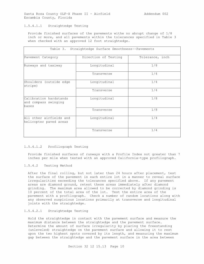
Santa Rosa County OLF-X Phase II – Airfield Addendum 002
Escambia County, Florida
Section 32 12 15.13 Page 10
1.5.4.1.1 Straightedge Testing
Provide finished surfaces of the pavements withe no abrupt change of 1/8
inch or more, and all pavements within the tolerances specified in Table 3
when checked with an approved 12 foot straightedge.
Table 3. Straightedge Surface Smoothness--Pavements
Pavement Category Direction of Testing Tolerance, inch
Runways and taxiway Longitudinal 1/8
Transverse 1/4
Shoulders (outside edge
stripe)
Longitudinal 1/4
Transverse 1/4
Calibration hardstands
and compass swinging
bases
Longitudinal 1/8
Transverse 1/8
All other airfields and
helicopter paved areas
Longitudinal 1/4
Transverse 1/4
1.5.4.1.2 Profilograph Testing
Provide finished surfaces of runways with a Profile Index not greater than 7
inches per mile when tested with an approved California-type profilograph.
1.5.4.2 Testing Method
After the final rolling, but not later than 24 hours after placement, test
the surface of the pavement in each entire lot in a manner to reveal surface
irregularities exceeding the tolerances specified above. If any pavement
areas are diamond ground, retest these areas immediately after diamond
grinding. The maximum area allowed to be corrected by diamond grinding is
10 percent of the total area of the lot. Test the entire area of the
pavement with a profilograph. Check a number of random locations along with
any observed suspicious locations primarily at transverse and longitudinal
joints with the straightedge.
1.5.4.2.1 Straightedge Testing
Hold the straightedge in contact with the pavement surface and measure the
maximum distance between the straightedge and the pavement surface.
Determine the amount of surface irregularity by placing the freestanding
(unleveled) straightedge on the pavement surface and allowing it to rest
upon the two highest spots covered by its length, and measuring the maximum
gap between the straightedge and the pavement surface in the area between
Santa Rosa County OLF-X Phase II – Airfield Addendum 002
Escambia County, Florida
Section 32 12 15.13 Page 11
these two high points. Use the straightedge to measure abrupt changes in
surface grade.
1.5.4.2.2 Profilograph Testing
Perform profilograph testing using an approved California profilograph and
procedures described in ASTM E1274. Provide equipment that utilizes
electronic recording and automatic computerized reduction of data to
indicate "must-grind" bumps and the Profile Index for the pavement. Use a
"blanking band" that is 0.2 inch wide and the "bump template" span 1 inch
with an offset of 0.4 inch. Provide profilograph operated by an approved,
factory-trained operator on the alignments specified above. Provide a copy
of the reduced tapes to the Owner's Representative at the end of each day's
testing.
1.5.4.2.3 Bumps ("Must Grind" Areas)
Reduce any bumps ("must grind" areas) shown on the profilograph trace which
exceed 0.4 inch in height by diamond grinding until they do not exceed 0.3
inch when retested. Taper diamond grinding in all directions to provide
smooth transitions to areas not requiring diamond grinding. The following
will not be permitted: (1) skin patching for correcting low areas, (2)
planing or milling for correcting high areas. At the Contractor's option,
pavement areas, including diamond ground areas, can be rechecked with the
profilograph in order to record a lower Profile Index.
1.6 ENVIRONMENTAL REQUIREMENTS
Do not place asphalt pavement upon a wet surface or when the surface
temperature of the underlying course is less than specified in Table 4. The
temperature requirements may be waived by the Owner's Representative, if
requested; provided all other requirements, including compaction, are met.
Table 4. Surface Temperature Limitations of Underlying Course
Mat Thickness, inches Degrees F
3 or greater 40
Less than 3 45
PART 2 PRODUCTS
2.1 SYSTEM DESCRIPTION
Perform the work consisting of pavement courses composed of mineral
aggregate and asphalt material heated and mixed in a central mixing plant
and placed on a prepared course. Provide hot-mix asphalt (HMA) pavement
designed and constructed in accordance with this section conforming to the
lines, grades, thicknesses, and typical cross sections shown on the
drawings. Construct each course to the depth, section, or elevation
required by the drawings and rolled, finished, and approved before the
placement of the next course. Submit proposed Placement Plan, indicating
lane widths, longitudinal joints, and transverse joints for each course or
lift.
Santa Rosa County OLF-X Phase II – Airfield Addendum 002
Escambia County, Florida
Section 32 12 15.13 Page 12
2.1.1 Asphalt Mixing Plant
Provide plants used for the preparation of asphalt mixture conforming to the
requirements of AASHTO M 156 with the following changes:
2.1.1.1 Truck Scales
Weigh the asphalt mixture on approved scales, or on certified public scales
at no additional expense to the Owner. Inspect and seal scales at least
annually by an approved calibration laboratory.
2.1.1.2 Inspection of Plant
Provide access to the Owner's Representative at all times, to all areas of
the plant for checking adequacy of equipment; inspecting operation of the
plant; verifying weights, proportions, and material properties; checking the
temperatures maintained in the preparation of the mixtures and for taking
samples. Provide assistance as requested, for the Owner's Representative to
procure any desired samples.
2.1.1.3 Storage Bins
The asphalt mixture may be stored in non-insulated storage bins for a period
of time not exceeding 3 hours. The asphalt mixture may be stored in
insulated storage bins for a period of time not exceeding 8 hours. Provide
the mix drawn from bins that meets the same requirements as mix loaded
directly into trucks.
2.1.2 Hauling Equipment
Provide trucks used for hauling asphalt mixture that have tight, clean, and
smooth metal beds. To prevent the mixture from adhering to them, Lightly
coat the truck beds with a minimum amount of paraffin oil, lime solution, or
other approved material. Do not use petroleum based products as a release
agent. Provide each truck with a suitable cover to protect the mixture from
adverse weather. When necessary to ensure that the mixture is delivered to
the site at the specified temperature, provide insulated or heated truck
beds with covers (tarps) that are securely fastened.
2.1.3 Material Transfer Vehicle (MTV)
Provide Material Transfer Vehicles for placement of the asphalt mixture. To
transfer the material from the hauling equipment to the paver, use a self-
propelled, material transfer vehicle with a swing conveyor that delivers
material to the paver from outside the paving lane and without making
contact with the paver. Provide MTV capable to move back and forth between
the hauling equipment and the paver providing material transfer to the
paver, while allowing the paver to operate at a constant speed. Provide
Material Transfer Vehicle with remixing and storage capability to prevent
physical and thermal segregation.
2.1.4 Asphalt Pavers
Provide mechanical spreading and finishing equipment consisting of a self-
powered paver, capable of spreading and finishing the mixture to the
specified line, grade, and cross section. Provide paver screed capable of
Santa Rosa County OLF-X Phase II – Airfield Addendum 002
Escambia County, Florida
Section 32 12 15.13 Page 13
laying a uniform mixture to meet the specified thickness, smoothness, and
grade without physical or temperature segregation, the full width of the
material being placed. Provide a screed equipped with a compaction device
to be used during all placement.
2.1.4.1 Receiving Hopper
Provide paver with a receiving hopper of sufficient capacity to permit a
uniform spreading operation and a distribution system to place the mixture
uniformly in front of the screed without segregation. Provide a screed that
effectively produces a finished surface of the required evenness and texture
without tearing, shoving, or gouging the mixture.
2.1.4.2 Automatic Grade Controls
If an automatic grade control device is used, provide a paver equipped with
a control system capable of automatically maintaining the specified screed
elevation that is automatically actuated from either a reference line or
through a system of mechanical sensors or sensor-directed mechanisms or
devices which maintain the paver screed at a predetermined transverse slope
and at the proper elevation to obtain the required surface. Provide
transverse slope controller capable of maintaining the screed at the desired
slope within plus or minus 0.1 percent. Do not use the transverse slope
controller to control grade. Provide controls capable of working in
conjunction with any of the following attachments:
a. Ski-type device of not less than 30 feet in length.
b. Taut stringline set to grade.
c. Short ski or shoe for joint matching.
d. Laser control.
2.1.5 Rollers
Provide rollers in good condition and operated at slow speeds to avoid
displacement of the asphalt mixture. Provide sufficient number, type, and
weight of rollers to compact the mixture to the required density while it is
still in a workable condition. Do not use equipment which causes excessive
crushing of the aggregate.
2.1.6 Diamond Grinding
Those performing diamond grinding are required to have a minimum of three
years experience in diamond grinding of airfield pavements. In areas not
meeting the specified limits for surface smoothness and plan grade, reduce
high areas to attain the required smoothness and grade, except as depth is
limited below. Reduce high areas by diamond grinding the asphalt pavement
with approved equipment after the asphalt pavement is at a minimum age of 14
days. Perform diamond grinding by sawing with saw blades impregnated with
an industrial diamond abrasive. Assemble the saw blades in a cutting head
mounted on a machine designed specifically for diamond grinding that
produces the required texture and smoothness level without damage to the
asphalt pavement or joint faces. Provide diamond grinding equipment with
saw blades that are 1/8-inch wide, a minimum of 60 blades per 12 inches of
cutting head width, and capable of cutting a path a minimum of 3 feet wide.
Santa Rosa County OLF-X Phase II – Airfield Addendum 002
Escambia County, Florida
Section 32 12 15.13 Page 14
Diamond grinding equipment that causes raveling, fracturing of aggregate ,
or disturbance to the underlying material will not be allowed. The maximum
area corrected by diamond grinding the surface of the asphalt pavement is 10
percent of the total area of any sublot. The maximum depth of diamond
grinding is 1/2 inch. Provide diamond grinding machine equipped to flush
and vacuum the pavement surface. Dispose of all debris from diamond
grinding operations off Owner property. Prior to diamond grinding, submit a
Diamond Grinding Plan for review and approval. At a minimum, include the
daily reports for the deficient areas, the location and extent of
deficiencies, corrective actions, and equipment. Remove and replace all
pavement areas requiring plan grade or surface smoothness corrections in
excess of the limits specified.
Prior to production diamond grinding operations, perform a test section at
the approved location, consisting of a minimum of two adjacent passes with a
minimum length of 40 feet to allow evaluation of the finish and transition
between adjacent passes. Production diamond grinding operations cannot be
performed prior to approval.
2.2 AGGREGATES
Sample aggregates in the presence of a Owner's Representative. Obtain
samples in accordance with ASTM D75/D75M and be representative of the
materials to be used for the project. Provide aggregates consisting of
crushed stone, crushed gravel, crushed slag, screenings, natural sand and
mineral filler, as required. The portion of material retained on the No. 4
sieve is coarse aggregate. The portion of material passing the No. 4 sieve
and retained on the No. 200 sieve is fine aggregate. The portion passing
the No. 200 sieve is defined as mineral filler. Submit sufficient materials
to produce 200 pounds of blended mixture for mix design verification.
Submit all aggregate test results and samples to the Owner's Representative
at least 14 days prior to start of construction. Perform job aggregate
testing no earlier than 6 months before contract award.
2.2.1 Coarse Aggregate
Provide coarse aggregate consisting of sound, tough, durable particles, free
from films of material that would prevent thorough coating and bonding with
the asphalt material and free from organic matter and other deleterious
substances. Provide coarse aggregate particles meeting the following
requirements:
a. The percentage of loss not be greater than 40 percent after 500
revolutions when tested in accordance with ASTM C131/C131M.
b. The sodium sulfate soundness loss not exceeding 12 percent, or the
magnesium sulfate soundness loss not exceeding 18 percent after five
cycles when tested in accordance with ASTM C88.
c. At least 75 percent by weight of coarse aggregate contain at least two
or more fractured faces when tested in accordance with ASTM D5821 with
fractured faces produced by crushing.
d. The particle shape essentially cubical and the aggregate containing not
more than 20 percent, by weight, of flat particles and elongated
particles (3:1 ratio of maximum to minimum) when tested in accordance
with ASTM D4791.
Santa Rosa County OLF-X Phase II – Airfield Addendum 002
Escambia County, Florida
Section 32 12 15.13 Page 15
e. Slag consisting of air-cooled, blast furnace slag, with a compacted
weight of not less than 75 pounds per cubic foot when tested in
accordance with ASTM C29/C29M.
f. Clay lumps and friable particles not exceeding 0.3 percent, by weight,
when tested in accordance with ASTM C142/C142M.
2.2.2 Fine Aggregate
Provide fine aggregate consisting of clean, sound, tough, durable particles.
Provide aggregate particles that are free from coatings of clay, silt, or
any objectionable material, contain no clay balls, and meet the following
requirements:
a. Quantity of natural sand (noncrushed material) added to the aggregate
blend not exceeding 15 percent by weight of total aggregate.
b. Individual fine aggregate sources with a sand equivalent value greater
than 45 when tested in accordance with ASTM D2419.
c. Fine aggregate portion of the blended aggregate with an uncompacted
void content greater than 45.0 percent when tested in accordance with
AASHTO T 304 Method A.
d. Clay lumps and friable particles not exceeding 0.3 percent, by weight,
when tested in accordance with ASTM C142/C142M.
2.2.3 Mineral Filler
Provide mineral filler consisting of a nonplastic material meeting the
requirements of ASTM D242/D242M.
2.2.4 Aggregate Gradation
Provide a combined aggregate gradation that conforms to gradations specified
in Table 5, when tested in accordance with ASTM C136/C136M and ASTM C117,
and does not vary from the low limit on one sieve to the high limit on the
adjacent sieve or vice versa, but grades uniformly from coarse to fine.
Provide a JMF within the specification limits; however, the gradation can
exceed the limits when the allowable deviation from the JMF shown in Tables
8 and 9 are applied.
Table 5. Aggregate Gradations
Gradation 2 Gradation 3
Sieve Size, inch Percent Passing by
Mass
Percent Passing by
Mass
1 --- ---
3/4 100 ---
1/2 90-100 100
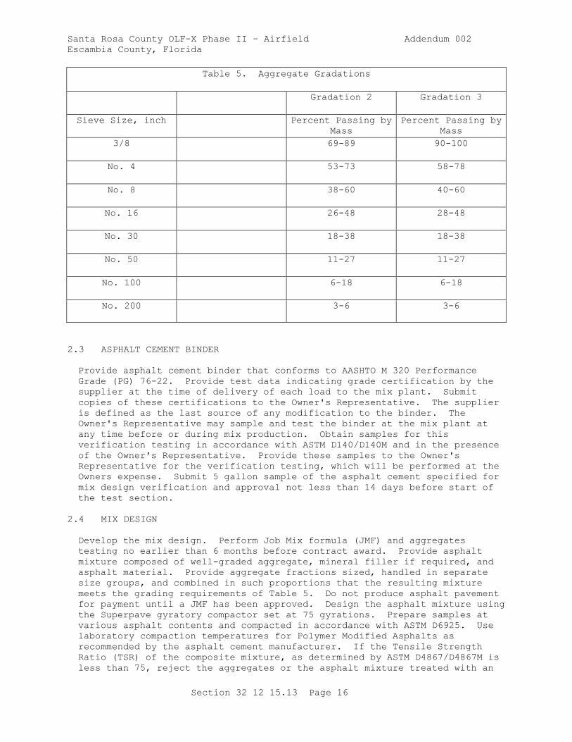
Santa Rosa County OLF-X Phase II – Airfield Addendum 002
Escambia County, Florida
Section 32 12 15.13 Page 16
Table 5. Aggregate Gradations
Gradation 2 Gradation 3
Sieve Size, inch Percent Passing by
Mass
Percent Passing by
Mass
3/8 69-89 90-100
No. 4 53-73 58-78
No. 8 38-60 40-60
No. 16 26-48 28-48
No. 30 18-38 18-38
No. 50 11-27 11-27
No. 100 6-18 6-18
No. 200 3-6 3-6
2.3 ASPHALT CEMENT BINDER
Provide asphalt cement binder that conforms to AASHTO M 320 Performance
Grade (PG) 76-22. Provide test data indicating grade certification by the
supplier at the time of delivery of each load to the mix plant. Submit
copies of these certifications to the Owner's Representative. The supplier
is defined as the last source of any modification to the binder. The
Owner's Representative may sample and test the binder at the mix plant at
any time before or during mix production. Obtain samples for this
verification testing in accordance with ASTM D140/D140M and in the presence
of the Owner's Representative. Provide these samples to the Owner's
Representative for the verification testing, which will be performed at the
Owners expense. Submit 5 gallon sample of the asphalt cement specified for
mix design verification and approval not less than 14 days before start of
the test section.
2.4 MIX DESIGN
Develop the mix design. Perform Job Mix formula (JMF) and aggregates
testing no earlier than 6 months before contract award. Provide asphalt
mixture composed of well-graded aggregate, mineral filler if required, and
asphalt material. Provide aggregate fractions sized, handled in separate
size groups, and combined in such proportions that the resulting mixture
meets the grading requirements of Table 5. Do not produce asphalt pavement
for payment until a JMF has been approved. Design the asphalt mixture using
the Superpave gyratory compactor set at 75 gyrations. Prepare samples at
various asphalt contents and compacted in accordance with ASTM D6925. Use
laboratory compaction temperatures for Polymer Modified Asphalts as
recommended by the asphalt cement manufacturer. If the Tensile Strength
Ratio (TSR) of the composite mixture, as determined by ASTM D4867/D4867M is
less than 75, reject the aggregates or the asphalt mixture treated with an
Santa Rosa County OLF-X Phase II – Airfield Addendum 002
Escambia County, Florida
Section 32 12 15.13 Page 17
anti-stripping agent. Add a sufficient amount of anti-stripping agent to
produce a TSR of not less than 75. If an antistrip agent is required,
provide it at no additional cost to the Owner Provide sufficient materials
to produce 200 pound of blended mixture to the Owner's Representative for
verification of mix design at least 14 days prior to construction of test
section.
2.4.1 JMF Requirements
Submit the proposed JMF in writing, for approval, at least 14 days prior to
the start of the test section, including as a minimum:
a. Percent passing each sieve size.
b. Percent of asphalt cement.
c. Percent of each aggregate and mineral filler to be used.
d. Asphalt viscosity grade, penetration grade, or performance grade.
e. Number of Superpave gyratory compactor gyrations.
f. Laboratory mixing temperature.
g. Lab compaction temperature.
h. Temperature-viscosity relationship of the asphalt cement.
i. Plot of the combined gradation on the 0.45 power gradation chart,
stating the nominal maximum size.
j. Graphical plots and summary tabulation of air voids, voids in the
mineral aggregate, and unit weight versus asphalt content as shown in
AI MS-2. Include summary tabulation that includes individual specimen
data for each specimen tested.
k. Specific gravity and absorption of each aggregate.
l. Percent natural sand.
m. Percent particles with two or more fractured faces (in coarse
aggregate).
n. Fine aggregate angularity.
o. Percent flat or elongated particles (in coarse aggregate).
p. Tensile Strength Ratio and wet/dry specimen test results.
q. Antistrip agent (if required).
r. List of all modifiers.
s. Percentage and properties (asphalt content aggregate gradation, and
aggregate properties) of RAP in accordance with paragraph RECYCLED
ASPHALT PAVEMENT, if RAP is used.
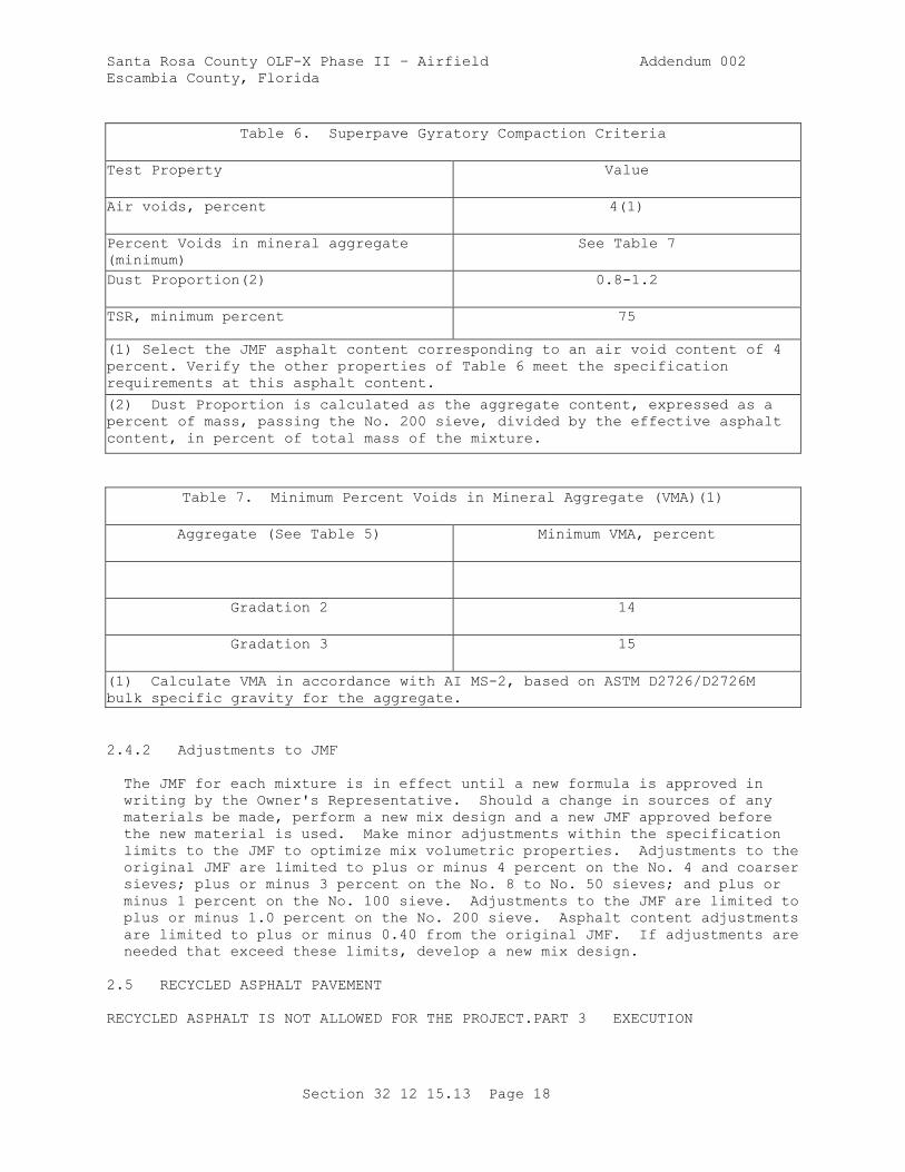
Santa Rosa County OLF-X Phase II – Airfield Addendum 002
Escambia County, Florida
Section 32 12 15.13 Page 18
Table 6. Superpave Gyratory Compaction Criteria
Test Property Value
Air voids, percent 4(1)
Percent Voids in mineral aggregate
(minimum)
See Table 7
Dust Proportion(2) 0.8-1.2
TSR, minimum percent 75
(1) Select the JMF asphalt content corresponding to an air void content of 4
percent. Verify the other properties of Table 6 meet the specification
requirements at this asphalt content.
(2) Dust Proportion is calculated as the aggregate content, expressed as a
percent of mass, passing the No. 200 sieve, divided by the effective asphalt
content, in percent of total mass of the mixture.
Table 7. Minimum Percent Voids in Mineral Aggregate (VMA)(1)
Aggregate (See Table 5) Minimum VMA, percent
Gradation 2 14
Gradation 3 15
(1) Calculate VMA in accordance with AI MS-2, based on ASTM D2726/D2726M
bulk specific gravity for the aggregate.
2.4.2 Adjustments to JMF
The JMF for each mixture is in effect until a new formula is approved in
writing by the Owner's Representative. Should a change in sources of any
materials be made, perform a new mix design and a new JMF approved before
the new material is used. Make minor adjustments within the specification
limits to the JMF to optimize mix volumetric properties. Adjustments to the
original JMF are limited to plus or minus 4 percent on the No. 4 and coarser
sieves; plus or minus 3 percent on the No. 8 to No. 50 sieves; and plus or
minus 1 percent on the No. 100 sieve. Adjustments to the JMF are limited to
plus or minus 1.0 percent on the No. 200 sieve. Asphalt content adjustments
are limited to plus or minus 0.40 from the original JMF. If adjustments are
needed that exceed these limits, develop a new mix design.
2.5 RECYCLED ASPHALT PAVEMENT
RECYCLED ASPHALT IS NOT ALLOWED FOR THE PROJECT.PART 3 EXECUTION
Santa Rosa County OLF-X Phase II – Airfield Addendum 002
Escambia County, Florida
Section 32 12 15.13 Page 19
3.1 CONTRACTOR QUALITY CONTROL
3.1.1 General Quality Control Requirements
Submit the Quality Control Plan. Do not produce hot-mix asphalt pavement
for payment until the quality control plan has been approved. In the
quality control plan, address all elements which affect the quality of the
pavement including, but not limited to:
a. Mix Design and unique JMF identification code
b. Aggregate Grading
c. Quality of Materials
d. Stockpile Management and procedures to prevent contamination
e. Proportioning
f. Mixing and Transportation
g. Correlation of mechanical hammer to hand hammer. Determine the number
of blows of the mechanical hammer required to provide the same density
of the JMF as provided by the hand hammer. Use the average of three
specimens per trial blow application.
h. Mixture Volumetrics
i. Moisture Content of Mixtures
j. Placing and Finishing
k. Joints
l. Compaction, including Asphalt Pavement-Portland Cement Concrete joints
m. Surface Smoothness
n. Truck bed release agent
3.1.2 Testing Laboratory
Provide a fully equipped asphalt laboratory located at the plant or job site
that is equipped with heating and air conditioning units to maintain a
temperature of 75 plus or minus 5 degrees F. Provide laboratory facilities
that are kept clean and all equipment maintained in proper working
condition. Provide the Owner's Representative with unrestricted access to
inspect the laboratory facility, to witness quality control activities, and
to perform any check testing desired. The Owner's Representative will
advise in writing of any noted deficiencies concerning the laboratory
facility, equipment, supplies, or testing personnel and procedures. When
the deficiencies are serious enough to adversely affect test results,
immediately suspend the incorporation of the materials into the work.
Incorporation of the materials into the work will not be permitted to resume
until the deficiencies are corrected.
Santa Rosa County OLF-X Phase II – Airfield Addendum 002
Escambia County, Florida
Section 32 12 15.13 Page 20
3.1.3 Quality Control Testing
Perform all quality control tests applicable to these specifications and as
set forth in the Quality Control Program. Required elements of the testing
program include, but are not limited to, tests for the control of asphalt
content, aggregate gradation, temperatures, aggregate moisture, moisture in
the asphalt mixture, laboratory air voids, stability, flow, in-place
density, grade and smoothness. Develop a Quality Control Testing Plan as
part of the Quality Control Program.
3.1.3.1 Asphalt Content
A minimum of two tests to determine asphalt content will be performed per
lot (a lot is defined in paragraph QUALITY ASSURANCE) by one of the
following methods: extraction method in accordance with ASTM D2172/D2172M,
Method A or B, the ignition method in accordance with the AASHTO T 308, ASTM
D6307, or the nuclear method in accordance with ASTM D4125/D4125M, provided
each method is calibrated for the specific mix being used. For the
extraction method, determine the weight of ash, as described in ASTM
D2172/D2172M, as part of the first extraction test performed at the
beginning of plant production; and as part of every tenth extraction test
performed thereafter, for the duration of plant production. Use the last
weight of ash value in the calculation of the asphalt content for the
mixture.
3.1.3.2 Aggregate Properties
Determine aggregate gradations a minimum of twice per lot from mechanical
analysis of recovered aggregate in accordance with ASTM D5444 or ASTM D6307.
For batch plants, test aggregatesin accordance with ASTM C136/C136M using
actual batch weights to determine the combined aggregate gradation of the
mixture. Determine the specific gravity of each aggregate size grouping for
each 20,000 tons in accordance with ASTM C127 or ASTM C128. Determine
fractured faces for gravel sources for each 20,000 tons in accordance with
ASTM D5821. Determine the uncompacted void content of manufactured sand for
each 20,000 tons in accordance with AASHTO T 304 Method A.
3.1.3.3 Temperatures
Check temperatures at least four times per lot, at necessary locations, to
determine the temperature at the dryer, the asphalt cement in the storage
tank, the asphalt mixture at the plant, and the asphalt mixture at the job
site.
3.1.3.4 Aggregate Moisture
Determine the moisture content of aggregate used for production a minimum of
once per lot in accordance with ASTM C566.
3.1.3.5 Moisture Content of Mixture
Determine the moisture content of the mixture at least once per lot in
accordance with AASHTO T 329.
3.1.3.6 Laboratory Air Voids, VMA

Santa Rosa County OLF-X Phase II – Airfield Addendum 002
Escambia County, Florida
Section 32 12 15.13 Page 21
Obtain mixture samples at least four times per lot and compacted into
specimens, using 75 gyrations of the Superpave gyratory compactor as
described in ASTM D6925. After compaction, dtermine the laboratory air
voids and VMA of each specimen. Provide VMA within the limits of Table 7.
3.1.3.7 In-Place Density
Conduct any necessary testing to ensure the specified density is achieved.
A nuclear gauge or other non-destructive testing device may be used to
monitor pavement density.
3.1.3.8 Grade and Smoothness
Conduct the necessary checks to ensure the grade and smoothness requirements
are met in accordance with paragraph QUALITY ASSURANCE.
3.1.3.9 Additional Testing
Perform any additional testing, deemed necessary to control the process.
3.1.3.10 QC Monitoring
Submit all QC test results to the Owner's Representative on a daily basis as
the tests are performed. The Owner's Representative reserves the right to
monitor any of the Contractor's quality control testing and to perform
duplicate testing as a check to the Contractor's quality control testing.
3.1.4 Sampling
When directed by the Owner's Representative, sample and test any material
which appears inconsistent with similar material being produced, unless such
material is voluntarily removed and replaced or deficiencies corrected.
Perform all sampling in accordance with standard procedures specified.
3.1.5 Control Charts
For process control, establish and maintain linear control charts on both
individual samples and the running average of last four samples for the
parameters listed in Table 8, as a minimum. Post the control charts as
directed by the Owner's Representative and maintain current at all times.
Identify the following on the control charts, the project number, the test
parameter being plotted, the individual sample numbers, the Action and
Suspension Limits listed in Table 8 applicable to the test parameter being
plotted, and the test results. Also show target values (JMF) on the control
charts as indicators of central tendency for the cumulative percent passing,
asphalt content, and laboratory air voids parameters. When the test results
exceed either applicable Action Limit, take immediate steps to bring the
process back in control. When the test results exceed either applicable
Suspension Limit, halt production until the problem is solved. When the
Suspension Limit is exceeded for individual values or running average
values, the Owner's Representative has the option to require removal and
replacement of the material represented by the samples or to leave in place
and base acceptance on mixture volumetric properties and in place density.
Use the control charts as part of the process control system for identifying
trends so that potential problems can be corrected before they occur. Make
decisions concerning mix modifications based on analysis of the results
provided in the control charts. In the Quality Control Plan, indicate the
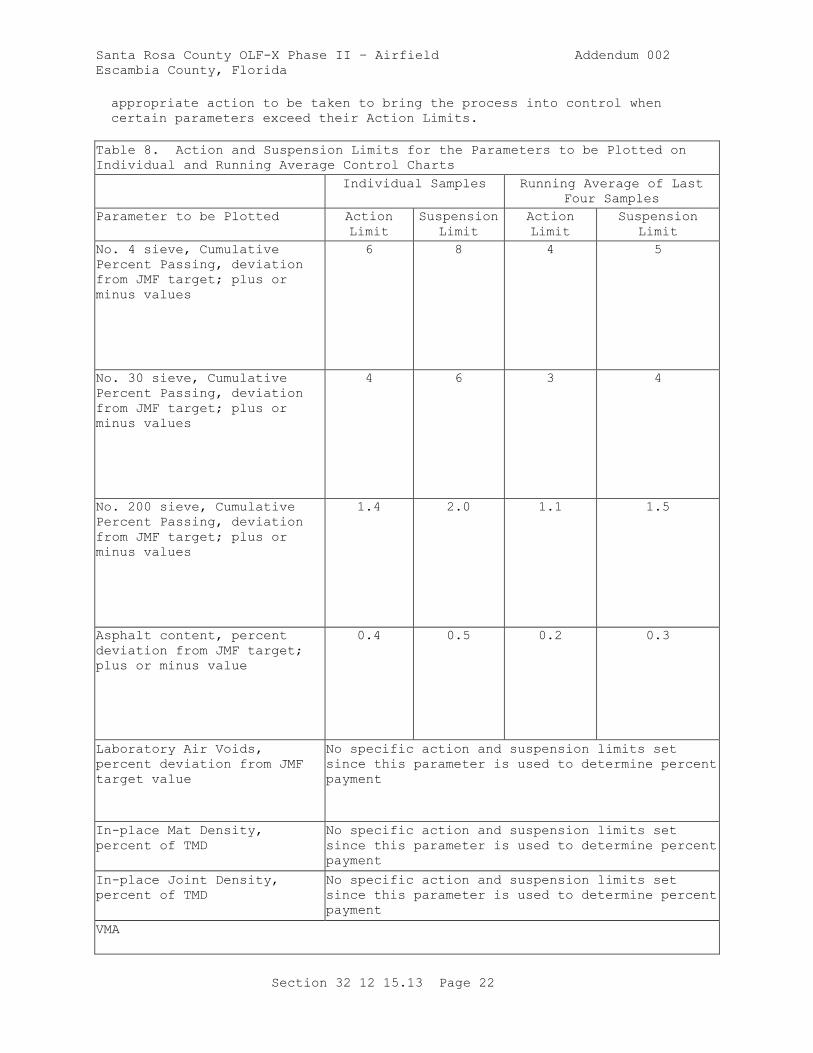
Santa Rosa County OLF-X Phase II – Airfield Addendum 002
Escambia County, Florida
Section 32 12 15.13 Page 22
appropriate action to be taken to bring the process into control when
certain parameters exceed their Action Limits.
Table 8. Action and Suspension Limits for the Parameters to be Plotted on
Individual and Running Average Control Charts
Individual Samples Running Average of Last
Four Samples
Parameter to be Plotted Action
Limit
Suspension
Limit
Action
Limit
Suspension
Limit
No. 4 sieve, Cumulative
Percent Passing, deviation
from JMF target; plus or
minus values
6 8 4 5
No. 30 sieve, Cumulative
Percent Passing, deviation
from JMF target; plus or
minus values
4 6 3 4
No. 200 sieve, Cumulative
Percent Passing, deviation
from JMF target; plus or
minus values
1.4 2.0 1.1 1.5
Asphalt content, percent
deviation from JMF target;
plus or minus value
0.4 0.5 0.2 0.3
Laboratory Air Voids,
percent deviation from JMF
target value
No specific action and suspension limits set
since this parameter is used to determine percent
payment
In-place Mat Density,
percent of TMD
No specific action and suspension limits set
since this parameter is used to determine percent
payment
In-place Joint Density,
percent of TMD
No specific action and suspension limits set
since this parameter is used to determine percent
payment
VMA
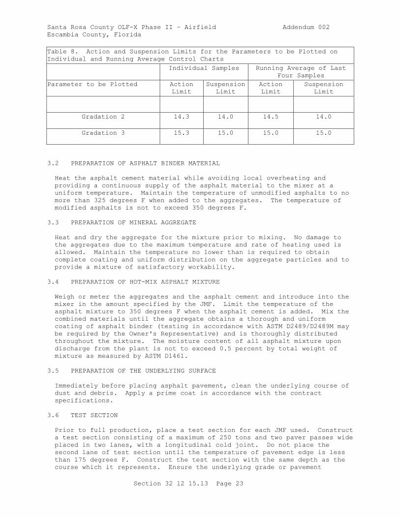
Santa Rosa County OLF-X Phase II – Airfield Addendum 002
Escambia County, Florida
Section 32 12 15.13 Page 23
Table 8. Action and Suspension Limits for the Parameters to be Plotted on
Individual and Running Average Control Charts
Individual Samples Running Average of Last
Four Samples
Parameter to be Plotted Action
Limit
Suspension
Limit
Action
Limit
Suspension
Limit
Gradation 2 14.3 14.0 14.5 14.0
Gradation 3 15.3 15.0 15.0 15.0
3.2 PREPARATION OF ASPHALT BINDER MATERIAL
Heat the asphalt cement material while avoiding local overheating and
providing a continuous supply of the asphalt material to the mixer at a
uniform temperature. Maintain the temperature of unmodified asphalts to no
more than 325 degrees F when added to the aggregates. The temperature of
modified asphalts is not to exceed 350 degrees F.
3.3 PREPARATION OF MINERAL AGGREGATE
Heat and dry the aggregate for the mixture prior to mixing. No damage to
the aggregates due to the maximum temperature and rate of heating used is
allowed. Maintain the temperature no lower than is required to obtain
complete coating and uniform distribution on the aggregate particles and to
provide a mixture of satisfactory workability.
3.4 PREPARATION OF HOT-MIX ASPHALT MIXTURE
Weigh or meter the aggregates and the asphalt cement and introduce into the
mixer in the amount specified by the JMF. Limit the temperature of the
asphalt mixture to 350 degrees F when the asphalt cement is added. Mix the
combined materials until the aggregate obtains a thorough and uniform
coating of asphalt binder (testing in accordance with ASTM D2489/D2489M may
be required by the Owner's Representative) and is thoroughly distributed
throughout the mixture. The moisture content of all asphalt mixture upon
discharge from the plant is not to exceed 0.5 percent by total weight of
mixture as measured by ASTM D1461.
3.5 PREPARATION OF THE UNDERLYING SURFACE
Immediately before placing asphalt pavement, clean the underlying course of
dust and debris. Apply a prime coat in accordance with the contract
specifications.
3.6 TEST SECTION
Prior to full production, place a test section for each JMF used. Construct
a test section consisting of a maximum of 250 tons and two paver passes wide
placed in two lanes, with a longitudinal cold joint. Do not place the
second lane of test section until the temperature of pavement edge is less
than 175 degrees F. Construct the test section with the same depth as the
course which it represents. Ensure the underlying grade or pavement
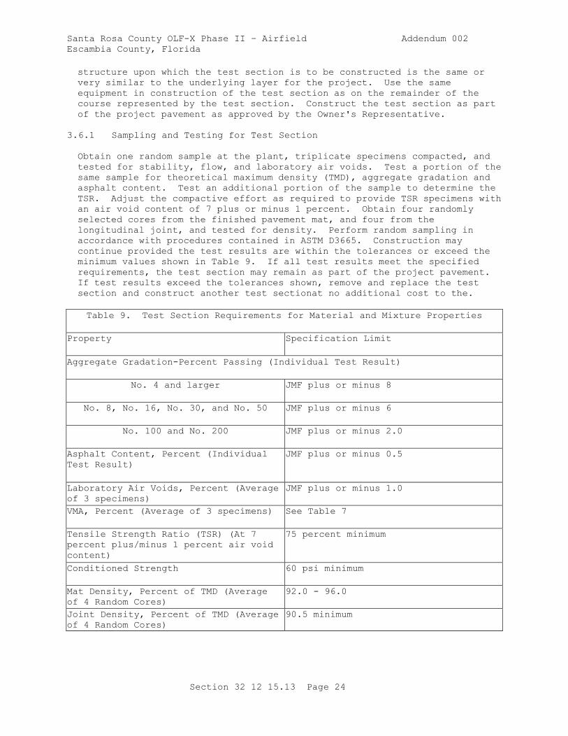
Santa Rosa County OLF-X Phase II – Airfield Addendum 002
Escambia County, Florida
Section 32 12 15.13 Page 24
structure upon which the test section is to be constructed is the same or
very similar to the underlying layer for the project. Use the same
equipment in construction of the test section as on the remainder of the
course represented by the test section. Construct the test section as part
of the project pavement as approved by the Owner's Representative.
3.6.1 Sampling and Testing for Test Section
Obtain one random sample at the plant, triplicate specimens compacted, and
tested for stability, flow, and laboratory air voids. Test a portion of the
same sample for theoretical maximum density (TMD), aggregate gradation and
asphalt content. Test an additional portion of the sample to determine the
TSR. Adjust the compactive effort as required to provide TSR specimens with
an air void content of 7 plus or minus 1 percent. Obtain four randomly
selected cores from the finished pavement mat, and four from the
longitudinal joint, and tested for density. Perform random sampling in
accordance with procedures contained in ASTM D3665. Construction may
continue provided the test results are within the tolerances or exceed the
minimum values shown in Table 9. If all test results meet the specified
requirements, the test section may remain as part of the project pavement.
If test results exceed the tolerances shown, remove and replace the test
section and construct another test sectionat no additional cost to the.
Table 9. Test Section Requirements for Material and Mixture Properties
Property Specification Limit
Aggregate Gradation-Percent Passing (Individual Test Result)
No. 4 and larger JMF plus or minus 8
No. 8, No. 16, No. 30, and No. 50 JMF plus or minus 6
No. 100 and No. 200 JMF plus or minus 2.0
Asphalt Content, Percent (Individual
Test Result)
JMF plus or minus 0.5
Laboratory Air Voids, Percent (Average
of 3 specimens)
JMF plus or minus 1.0
VMA, Percent (Average of 3 specimens) See Table 7
Tensile Strength Ratio (TSR) (At 7
percent plus/minus 1 percent air void
content)
75 percent minimum
Conditioned Strength 60 psi minimum
Mat Density, Percent of TMD (Average
of 4 Random Cores)
92.0 - 96.0
Joint Density, Percent of TMD (Average
of 4 Random Cores)
90.5 minimum
Santa Rosa County OLF-X Phase II – Airfield Addendum 002
Escambia County, Florida
Section 32 12 15.13 Page 25
3.6.2 Additional Test Sections
If the initial test section proves to be unacceptable, make the necessary
adjustments to the JMF, plant operation, placing procedures, and rolling
procedures before beginning construction of a second test section.
Construct and evaluate additional test sections, as required, for
conformance to the specifications. Full production paving is not allowed
until an acceptable test section has been constructed and accepted.
3.7 TESTING LABORATORY
Laboratories used to develop the JMF, perform Contractor Quality Control
testing, and quality assurance and acceptance testing are required to meet
the requirements of ASTM D3666. Perform all required test methods by an
accredited laboratory. Submit a certification of compliance signed by the
manager of the laboratory stating that it meets these requirements to the
Owner's Representative prior to the start of construction. At a minimum,
include the following certifications:
a. Qualifications of personnel; laboratory manager, supervising
technician, and testing technicians.
b. A listing of equipment to be used in developing the job mix.
c. A copy of the laboratory's quality control system.
d. Evidence of participation in the AASHTO Materials Reference Laboratory
(AMRL) program.
3.8 TRANSPORTING AND PLACING
3.8.1 Transporting
Transport asphalt mixture from the mixing plant to the site in clean, tight
vehicles. Schedule deliveries so that placing and compacting of mixture is
uniform with minimum stopping and starting of the paver. Provide adequate
artificial lighting for night placements. Hauling over freshly placed
material is not permitted until the material has been compacted as
specified, and allowed to cool to 140 degrees F.
3.8.2 Placing
Place the mix in lifts of adequate thickness and compacted at a temperature
suitable for obtaining density, surface smoothness, and other specified
requirements. Upon arrival, place the mixture to the full width by an
asphalt paver; strike off in a uniform layer of such depth that, when the
work is completed, the required thickness and conform to the grade and
contour indicated. Do not broadcast waste mixture onto the mat or recycled
into the paver hopper. Collect waste mixture and dispose off site.
Regulate the speed of the paver to eliminate pulling and tearing of the
asphalt mat. Begin placement of the mixture along the centerline of a
crowned section or on the high side of areas with a one-way slope. Place
the mixture in consecutive adjacent strips having a minimum width of 10
feet. Offset the longitudinal joint in one course from the longitudinal
joint in the course immediately below by at least 1 foot; however, locate
the joint in the surface course at the centerline of the pavement. Offset
transverse joints in one course by at least 10 feet from transverse joints
Santa Rosa County OLF-X Phase II – Airfield Addendum 002
Escambia County, Florida
Section 32 12 15.13 Page 26
in the previous course. Offset transverse joints in adjacent lanes a
minimum of 10 feet. On isolated areas where irregularities or unavoidable
obstacles make the use of mechanical spreading and finishing equipment
impractical, the mixture may be spread and luted by hand tools.
3.9 COMPACTION OF MIXTURE
3.9.1 General
a. After placing, thoroughly and uniformly compact the mixture by rolling.
Compact the surface as soon as possible without causing displacement,
cracking or shoving. Determine the sequence of rolling operations and
the type of rollers used, except as specified in paragraph ASPHALT
PAVEMENT-PORTLAND CEMENT CONCRETE JOINTS and with the exception that
application of more than three passes with a vibratory roller in the
vibrating mode is prohibited. Maintan the speed of the roller, at all
times, sufficiently slow to avoid displacement of the asphalt mixture
and be effective in compaction. Correct at once any displacement
occurring as a result of reversing the direction of the roller, or from
any other cause.
b. Furnish sufficient rollers to handle the output of the plant. Continue
rolling until the surface is of uniform texture, true to grade and
cross section, and the required field density is obtained. To prevent
adhesion of the mixture to the roller, keep the wheels properly
moistened, but excessive water is not permitted. In areas not
accessible to the roller, thoroughly compact the mixture with hand
tampers. Remove the full depth of any mixture that becomes loose and
broken, mixed with dirt, contains check-cracking, or is in any way
defective, replace with fresh asphalt mixture and immediately compact
to conform to the surrounding area. Perform this work at no expense to
the Owner. Skin patching is not allowed.
3.9.2 Segregation
The Owner's Representative can sample and test any material that looks
deficient. When the in-place material appears to be segregated, the Owner's
Representative has the option to sample the material and have it tested and
compared to the aggregate gradation, asphalt content, and in-place density
requirements in Table 9. If the material fails to meet these specification
requirements, remove and replace the extent of the segregated material the
full depth of the layer of asphalt mixture at no additional cost to the
Owner. When segregation occurs in the mat, take appropriate action to
correct the process so that additional segregation does not occur.
3.10 JOINTS
Construct joints to ensure a continuous bond between the courses and to
obtain the required density. Provide all joints with the same texture as
other sections of the course and meet the requirements for smoothness and
grade.
3.10.1 Transverse Joints
Do not pass the roller over the unprotected end of the freshly laid mixture,
except when necessary to form a transverse joint. When necessary to form a
transverse joint, construct by means of placing a bulkhead or by tapering
Santa Rosa County OLF-X Phase II – Airfield Addendum 002
Escambia County, Florida
Section 32 12 15.13 Page 27
the course. Utilize a dry saw cut on the transverse joint full depth and
width on a straight line to expose a vertical face prior to placing the
adjacent lane. Cutting equipment that uses water as a cooling or cutting
agent nor milling equipment is permitted. Remove the cutback material from
the project. In both methods, provide a light tack coat of asphalt material
to all contact surfaces before placing any fresh mixture against the joint.
3.10.2 Longitudinal Joints
Cut back longitudinal joints which are irregular, damaged, uncompacted, cold
(less than 175 degrees F at the time of placing the adjacent lane), or
otherwise defective, a maximum of 3 inches from the top edge of the lift
with a cutting wheel to expose a clean, sound, near vertical surface for the
full depth of the course. Remove all cutback material from the project.
Cutting equipment that uses water as a cooling or cutting agent nor milling
equipment is permitted. Provide a light tack coat of asphalt material to
all contact surfaces prior to placing any fresh mixture against the joint.
-- End of Section --
Santa Rosa County OLF-X Phase II – Airfield Addendum 002
Escambia County, Florida
Section 32 12 16 Page 1
SECTION 32 12 16
HOT-MIX ASPHALT (HMA) FOR ROADS
PART 1 GENERAL
1.1 UNIT PRICES
1.1.1 Method of Measurement
The amount paid for will be the number of short tons of hot-mix asphalt
mixture used in the accepted work. Weigh hot-mix asphalt mixture after
mixing, and no separate payment will be made for weight of asphalt cement
material incorporated herein.
1.1.2 Basis of Payment
Quantities of hot-mix asphalt mixtures, determined as specified above, will
be paid for at respective contract unit prices or at reduced prices adjusted
in accordance with paragraphs MATERIAL ACCEPTANCE and PERCENT PAYMENT.
Payment will constitute full compensation for furnishing all materials,
equipment, plant, and tools; and for all labor and other incidentals
necessary to complete work required by this section of the specification.
1.1.3 Percent Payment
Submit pay calculations. When a lot of material fails to meet the
specification requirements for 100 percent pay, as outlined in the following
paragraphs, that lot shall be removed and replaced, or accepted at a reduced
price which will be computed by multiplying the unit price by the lot's pay
factor. The lot pay factor is determined by taking the lowest computed pay
factor based on either laboratory air voids, in-place density, grade or
smoothness (each discussed below). At the end of the project, an average of
all lot pay factors will be calculated. If this average lot pay factor
equals or exceeds 95.0 percent, and no individual lot has a pay factor less
than 75.1 percent, then the percent payment for the entire project will be
100 percent of the unit bid price. If the average lot pay factor is less
than 95.0 percent, then each lot will be paid for at the unit price
multiplied by the lot's pay factor. For any lots which are less than 2000
short tons, a weighted lot pay factor will be used to calculate the average
lot pay factor.
1.1.4 Laboratory Air Voids and Theoretical Maximum Density
Laboratory air voids will be calculated by determining the Marshall or
Superpave density of each lab compacted specimen using the laboratory-
prepared, thoroughly dry method of ASTM D2726/D2726M and determining the
theoretical maximum density of every other sublot sample using ASTM
D2041/D2041M. Laboratory air void calculations for each sublot will use the
latest theoretical maximum density values obtained, either for that sublot
or the previous sublot. The mean absolute deviation of the four laboratory
air void contents (one from each sublot) from the JMF air void content will
be evaluated and a pay factor determined from Table 1. All laboratory air
void tests will be completed and reported within 24 hours after completion
of construction of each lot.
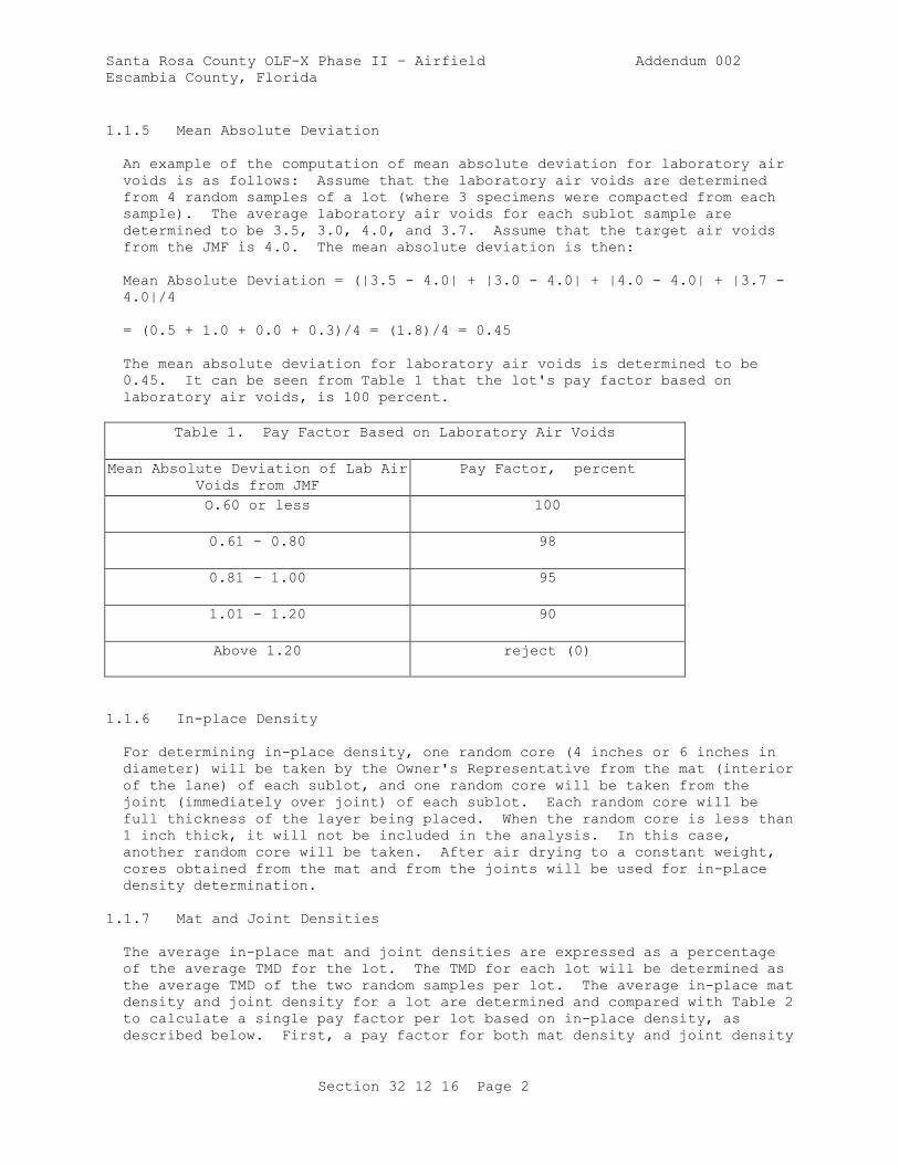
Santa Rosa County OLF-X Phase II – Airfield Addendum 002
Escambia County, Florida
Section 32 12 16 Page 2
1.1.5 Mean Absolute Deviation
An example of the computation of mean absolute deviation for laboratory air
voids is as follows: Assume that the laboratory air voids are determined
from 4 random samples of a lot (where 3 specimens were compacted from each
sample). The average laboratory air voids for each sublot sample are
determined to be 3.5, 3.0, 4.0, and 3.7. Assume that the target air voids
from the JMF is 4.0. The mean absolute deviation is then:
Mean Absolute Deviation = (|3.5 - 4.0| + |3.0 - 4.0| + |4.0 - 4.0| + |3.7 -
4.0|/4
= (0.5 + 1.0 + 0.0 + 0.3)/4 = (1.8)/4 = 0.45
The mean absolute deviation for laboratory air voids is determined to be
0.45. It can be seen from Table 1 that the lot's pay factor based on
laboratory air voids, is 100 percent.
Table 1. Pay Factor Based on Laboratory Air Voids
Mean Absolute Deviation of Lab Air
Voids from JMF
Pay Factor, percent
O.60 or less 100
0.61 - 0.80 98
0.81 - 1.00 95
1.01 - 1.20 90
Above 1.20 reject (0)
1.1.6 In-place Density
For determining in-place density, one random core (4 inches or 6 inches in
diameter) will be taken by the Owner's Representative from the mat (interior
of the lane) of each sublot, and one random core will be taken from the
joint (immediately over joint) of each sublot. Each random core will be
full thickness of the layer being placed. When the random core is less than
1 inch thick, it will not be included in the analysis. In this case,
another random core will be taken. After air drying to a constant weight,
cores obtained from the mat and from the joints will be used for in-place
density determination.
1.1.7 Mat and Joint Densities
The average in-place mat and joint densities are expressed as a percentage
of the average TMD for the lot. The TMD for each lot will be determined as
the average TMD of the two random samples per lot. The average in-place mat
density and joint density for a lot are determined and compared with Table 2
to calculate a single pay factor per lot based on in-place density, as
described below. First, a pay factor for both mat density and joint density
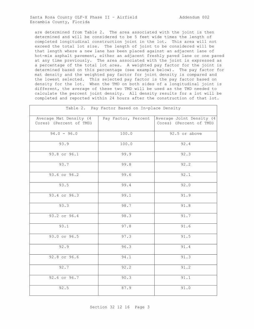
Santa Rosa County OLF-X Phase II – Airfield Addendum 002
Escambia County, Florida
Section 32 12 16 Page 3
are determined from Table 2. The area associated with the joint is then
determined and will be considered to be 5 feet wide times the length of
completed longitudinal construction joint in the lot. This area will not
exceed the total lot size. The length of joint to be considered will be
that length where a new lane has been placed against an adjacent lane of
hot-mix asphalt pavement, either an adjacent freshly paved lane or one paved
at any time previously. The area associated with the joint is expressed as
a percentage of the total lot area. A weighted pay factor for the joint is
determined based on this percentage (see example below). The pay factor for
mat density and the weighted pay factor for joint density is compared and
the lowest selected. This selected pay factor is the pay factor based on
density for the lot. When the TMD on both sides of a longitudinal joint is
different, the average of these two TMD will be used as the TMD needed to
calculate the percent joint density. All density results for a lot will be
completed and reported within 24 hours after the construction of that lot.
Table 2. Pay Factor Based on In-place Density
Average Mat Density (4
Cores) (Percent of TMD)
Pay Factor, Percent Average Joint Density (4
Cores) (Percent of TMD)
94.0 - 96.0 100.0 92.5 or above
93.9 100.0 92.4
93.8 or 96.1 99.9 92.3
93.7 99.8 92.2
93.6 or 96.2 99.6 92.1
93.5 99.4 92.0
93.4 or 96.3 99.1 91.9
93.3 98.7 91.8
93.2 or 96.4 98.3 91.7
93.1 97.8 91.6
93.0 or 96.5 97.3 91.5
92.9 96.3 91.4
92.8 or 96.6 94.1 91.3
92.7 92.2 91.2
92.6 or 96.7 90.3 91.1
92.5 87.9 91.0
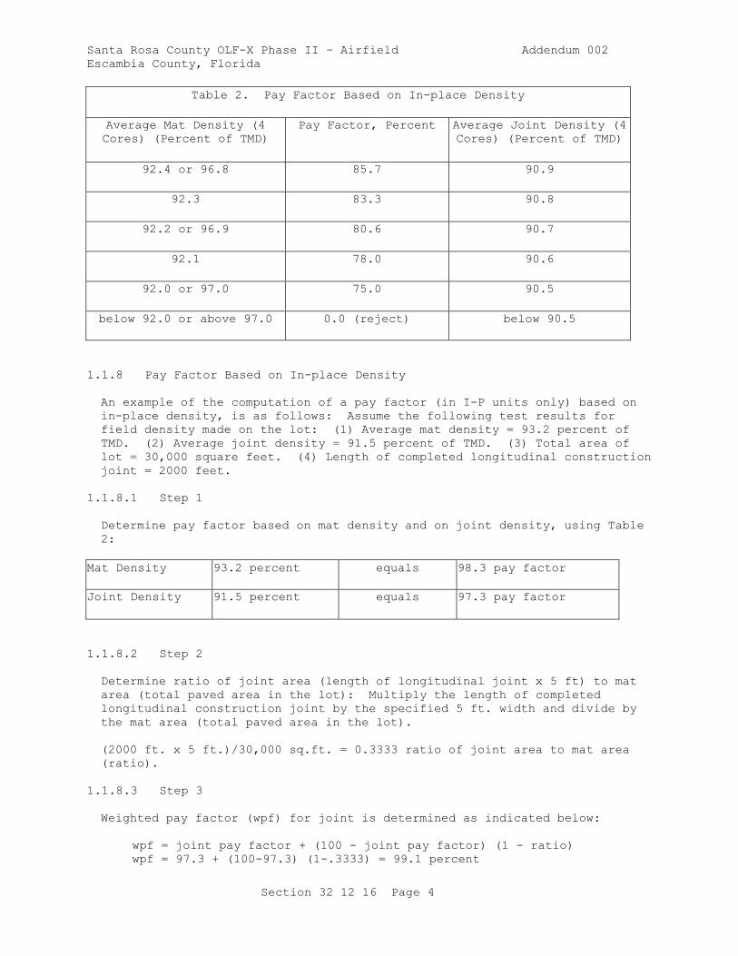
Santa Rosa County OLF-X Phase II – Airfield Addendum 002
Escambia County, Florida
Section 32 12 16 Page 4
Table 2. Pay Factor Based on In-place Density
Average Mat Density (4
Cores) (Percent of TMD)
Pay Factor, Percent Average Joint Density (4
Cores) (Percent of TMD)
92.4 or 96.8 85.7 90.9
92.3 83.3 90.8
92.2 or 96.9 80.6 90.7
92.1 78.0 90.6
92.0 or 97.0 75.0 90.5
below 92.0 or above 97.0 0.0 (reject) below 90.5
1.1.8 Pay Factor Based on In-place Density
An example of the computation of a pay factor (in I-P units only) based on
in-place density, is as follows: Assume the following test results for
field density made on the lot: (1) Average mat density = 93.2 percent of
TMD. (2) Average joint density = 91.5 percent of TMD. (3) Total area of
lot = 30,000 square feet. (4) Length of completed longitudinal construction
joint = 2000 feet.
1.1.8.1 Step 1
Determine pay factor based on mat density and on joint density, using Table
2:
Mat Density 93.2 percent equals 98.3 pay factor
Joint Density 91.5 percent equals 97.3 pay factor
1.1.8.2 Step 2
Determine ratio of joint area (length of longitudinal joint x 5 ft) to mat
area (total paved area in the lot): Multiply the length of completed
longitudinal construction joint by the specified 5 ft. width and divide by
the mat area (total paved area in the lot).
(2000 ft. x 5 ft.)/30,000 sq.ft. = 0.3333 ratio of joint area to mat area
(ratio).
1.1.8.3 Step 3
Weighted pay factor (wpf) for joint is determined as indicated below:
wpf = joint pay factor + (100 - joint pay factor) (1 - ratio)
wpf = 97.3 + (100-97.3) (1-.3333) = 99.1 percent
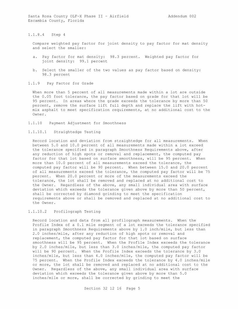
Santa Rosa County OLF-X Phase II – Airfield Addendum 002
Escambia County, Florida
Section 32 12 16 Page 5
1.1.8.4 Step 4
Compare weighted pay factor for joint density to pay factor for mat density
and select the smaller:
a. Pay factor for mat density: 98.3 percent. Weighted pay factor for
joint density: 99.1 percent
b. Select the smaller of the two values as pay factor based on density:
98.3 percent
1.1.9 Pay Factor for Grade
When more than 5 percent of all measurements made within a lot are outside
the 0.05 foot tolerance, the pay factor based on grade for that lot will be
95 percent. In areas where the grade exceeds the tolerance by more than 50
percent, remove the surface lift full depth and replace the lift with hot-
mix asphalt to meet specification requirements, at no additional cost to the
Owner.
1.1.10 Payment Adjustment for Smoothness
1.1.10.1 Straightedge Testing
Record location and deviation from straightedge for all measurements. When
between 5.0 and 10.0 percent of all measurements made within a lot exceed
the tolerance specified in paragraph Smoothness Requirements above, after
any reduction of high spots or removal and replacement, the computed pay
factor for that lot based on surface smoothness, will be 95 percent. When
more than 10.0 percent of all measurements exceed the tolerance, the
computed pay factor will be 90 percent. When between 15.0 and 20.0 percent
of all measurements exceed the tolerance, the computed pay factor will be 75
percent. When 20.0 percent or more of the measurements exceed the
tolerance, the lot shall be removed and replaced at no additional cost to
the Owner. Regardless of the above, any small individual area with surface
deviation which exceeds the tolerance given above by more than 50 percent,
shall be corrected by diamond grinding to meet the specification
requirements above or shall be removed and replaced at no additional cost to
the Owner.
1.1.10.2 Profilograph Testing
Record location and data from all profilograph measurements. When the
Profile Index of a 0.1 mile segment of a lot exceeds the tolerance specified
in paragraph Smoothness Requirements above by 1.0 inch/mile, but less than
2.0 inches/mile, after any reduction of high spots or removal and
replacement, the computed pay factor for that lot based on surface
smoothness will be 95 percent. When the Profile Index exceeds the tolerance
by 2.0 inches/mile, but less than 3.0 inches/mile, the computed pay factor
will be 90 percent. When the Profile Index exceeds the tolerance by 3.0
inches/mile, but less than 4.0 inches/mile, the computed pay factor will be
75 percent. When the Profile Index exceeds the tolerance by 4.0 inches/mile
or more, the lot shall be removed and replaced at no additional cost to the
Owner. Regardless of the above, any small individual area with surface
deviation which exceeds the tolerance given above by more than 5.0
inches/mile or more, shall be corrected by grinding to meet the
Santa Rosa County OLF-X Phase II – Airfield Addendum 002
Escambia County, Florida
Section 32 12 16 Page 6
specification requirements above or shall be removed and replaced at no
additional cost to the Owner.
1.1.10.3 Bumps ("Must Grind" Areas)
Any bumps ("must grind" areas) shown on the profilograph trace which exceed
0.3 inch in height shall be reduced by diamond grinding until they do not
exceed 0.3 inch when retested. Such grinding shall be tapered in all
directions to provide smooth transitions to areas not requiring grinding.
The following will not be permitted: (1) skin patching for correcting low
areas, (2) planing or milling for correcting high areas. At the
Contractor's option, pavement areas, including ground areas, may be
rechecked with the profilograph in order to record a lower Profile Index.
1.2 REFERENCES
The publications listed below form a part of this specification to the
extent referenced. The publications are referred to within the text by the
basic designation only.
AMERICAN ASSOCIATION OF STATE HIGHWAY AND TRANSPORTATION OFFICIALS
(AASHTO)
AASHTO M 156 (2013; R 2017) Standard Specification for
Requirements for Mixing Plants for Hot-Mixed,
Hot-Laid Bituminous Paving Mixtures
AASHTO M 320 (2017) Standard Specification for
Performance-Graded Asphalt Binder
AASHTO T 304 (2011; R 2015) Standard Method of Test for
Uncompacted Void Content of Fine Aggregate
ASPHALT INSTITUTE (AI)
AI MS-2 (2015) Asphalt Mix Design Methods
AI MS-22 (2001; 2nd Ed) Construction of Hot-Mix
Asphalt Pavements
AI SP-2 (2001; 3rd Ed) Superpave Mix Design
ASTM INTERNATIONAL (ASTM)
ASTM C117 (2017) Standard Test Method for Materials
Finer than 75-um (No. 200) Sieve in Mineral
Aggregates by Washing
ASTM C127 (2015) Standard Test Method for Density,
Relative Density (Specific Gravity), and
Absorption of Coarse Aggregate
ASTM C128 (2015) Standard Test Method for Density,
Relative Density (Specific Gravity), and
Absorption of Fine Aggregate

Santa Rosa County OLF-X Phase II – Airfield Addendum 002
Escambia County, Florida
Section 32 12 16 Page 7
ASTM C131/C131M (2014) Standard Test Method for Resistance to
Degradation of Small-Size Coarse Aggregate by
Abrasion and Impact in the Los Angeles
Machine
ASTM C136/C136M (2014) Standard Test Method for Sieve
Analysis of Fine and Coarse Aggregates
ASTM C142/C142M (2017) Standard Test Method for Clay Lumps
and Friable Particles in Aggregates
ASTM C29/C29M (2017a) Standard Test Method for Bulk Density
("Unit Weight") and Voids in Aggregate
ASTM C566 (2013) Standard Test Method for Total
Evaporable Moisture Content of Aggregate by
Drying
ASTM C88 (2013) Standard Test Method for Soundness of
Aggregates by Use of Sodium Sulfate or
Magnesium Sulfate
ASTM D1461 (2017) Standard Test Method for Moisture or
Volatile Distillates in Asphalt Mixtures
ASTM D2041/D2041M (2011) Theoretical Maximum Specific Gravity
and Density of Bituminous Paving Mixtures
ASTM D2172/D2172M (2017) Standard Test Methods for Quantitative
Extraction of Asphalt Binder from Asphalt
Mixtures
ASTM D2419 (2014) Sand Equivalent Value of Soils and
Fine Aggregate
ASTM D242/D242M (2009; R 2014) Mineral Filler for Bituminous
Paving Mixtures
ASTM D2489/D2489M (2016) Standard Test Method for Estimating
Degree of Particle Coating of Asphalt
Mixtures
ASTM D2726/D2726M (2017) Standard Test Method for Bulk Specific
Gravity and Density of Non-Absorptive
Compacted Bituminous Mixtures
ASTM D2950/D2950M (2014) Density of Bituminous Concrete in
Place by Nuclear Methods
ASTM D3665 (2012) Random Sampling of Construction
Materials
ASTM D3666 (2016) Standard Specification for Minimum
Requirements for Agencies Testing and
Inspecting Road and Paving Materials
Santa Rosa County OLF-X Phase II – Airfield Addendum 002
Escambia County, Florida
Section 32 12 16 Page 8
ASTM D4125/D4125M (2010) Asphalt Content of Bituminous Mixtures
by the Nuclear Method
ASTM D4791 (2010) Flat Particles, Elongated Particles,
or Flat and Elongated Particles in Coarse
Aggregate
ASTM D4867/D4867M (2009; R 2014) Effect of Moisture on Asphalt
Concrete Paving Mixtures
ASTM D5444 (2015) Mechanical Size Analysis of Extracted
Aggregate
ASTM D6307 (2016) Standard Test Method for Asphalt
Content of Hot Mix Asphalt by Ignition Method
ASTM D6925 (2014) Standard Test Method for Preparation
and Determination of the Relative Density of
Hot Mix Asphalt (HMA) Specimens by Means of
the Superpave Gyratory Compactor
ASTM D6926 (2016) Standard Practice for Preparation of
Asphalt Mixture Specimens Using Marshall
Apparatus
ASTM D6927 (2015) Standard Test Method for Marshall
Stability and Flow of Bituminous Mixtures
STATE OF CALIFORNIA DEPARTMENT OF TRANSPORTATION (CALTRANS)
CTM 526 (2002) Operation of California Profilograph
and Evaluation of Profiles
U.S. ARMY CORPS OF ENGINEERS (USACE)
COE CRD-C 171 (1995) Standard Test Method for Determining
Percentage of Crushed Particles in Aggregate
1.3 SUBMITTALS
Owner approval is required for submittals with a "G" designation; submittals
not having a "G" designation are for information only. Submit the following
in accordance with Section 01 33 00 SUBMITTAL PROCEDURES:
SD-03 Product Data
Mix Design; G
Quality Control; G
Material Acceptance; G
Percent Payment; G
SD-04 Samples
Asphalt Cement Binder
Santa Rosa County OLF-X Phase II – Airfield Addendum 002
Escambia County, Florida
Section 32 12 16 Page 9
Aggregates
SD-06 Test Reports
Aggregates; G
QC Monitoring
SD-07 Certificates
Asphalt Cement Binder; G
Testing Laboratory
1.4 ENVIRONMENTAL REQUIREMENTS
Do not place the hot-mix asphalt upon a wet surface or when the surface
temperature of the underlying course is less than specified in Table 3. The
temperature requirements may be waived by the Owner's Representative, if
requested; however, meet all other requirements, including compaction.
Table 3. Surface Temperature Limitations of Underlying Course
Mat Thickness, inches Degrees F
3 or greater 40
Less than 3 45
PART 2 PRODUCTS
2.1 SYSTEM DESCRIPTION
Perform the work consisting of pavement courses composed of mineral
aggregate and asphalt material heated and mixed in a central mixing plant
and placed on a prepared course. HMA designed and constructed in accordance
with this section shall conform to the lines, grades, thicknesses, and
typical cross sections indicated. Construct each course to the depth,
section, or elevation required by the drawings and roll, finish, and approve
it before the placement of the next course.
2.1.1 Asphalt Mixing Plant
Plants used for the preparation of hot-mix asphalt shall conform to the
requirements of AASHTO M 156 with the following changes:
2.1.1.1 Truck Scales
Weigh the asphalt mixture on approved, certified scales at the Contractor's
expense. Inspect and seal scales at least annually by an approved
calibration laboratory.
Santa Rosa County OLF-X Phase II – Airfield Addendum 002
Escambia County, Florida
Section 32 12 16 Page 10
2.1.1.2 Testing Facilities
Provide laboratory facilities at the plant for the use of the Owner's
acceptance testing and the Contractor's quality control testing.
2.1.1.3 Inspection of Plant
Provide the Owner's Representative with access at all times, to all areas of
the plant for checking adequacy of equipment; inspecting operation of the
plant; verifying weights, proportions, and material properties; checking the
temperatures maintained in the preparation of the mixtures and for taking
samples. Provide assistance as requested, for the Owner's Representative to
procure any desired samples.
2.1.1.4 Storage bins
Use of storage bins for temporary storage of hot-mix asphalt will be
permitted as follows:
a. The asphalt mixture may be stored in non-insulated storage bins for a
period of time not exceeding 3 hours.
b. The asphalt mixture may be stored in insulated storage bins for a
period of time not exceeding 8 hours. The mix drawn from bins shall
meet the same requirements as mix loaded directly into trucks.
2.1.2 Hauling Equipment
Provide trucks for hauling hot-mix asphalt having tight, clean, and smooth
metal beds. To prevent the mixture from adhering to them, the truck beds
shall be lightly coated with a minimum amount of paraffin oil, lime
solution, or other approved material. Petroleum based products shall not be
used as a release agent. Each truck shall have a suitable cover to protect
the mixture from adverse weather. When necessary to ensure that the mixture
will be delivered to the site at the specified temperature, truck beds shall
be insulated or heated and covers (tarps) shall be securely fastened.
2.1.3 Asphalt Pavers
Provide asphalt pavers which are self-propelled, with an activated screed,
heated as necessary, and capable of spreading and finishing courses of hot-
mix asphalt which will meet the specified thickness, smoothness, and grade.
The paver shall have sufficient power to propel itself and the hauling
equipment without adversely affecting the finished surface.
2.1.3.1 Receiving Hopper
Provide paver with a receiving hopper of sufficient capacity to permit a
uniform spreading operation and equipped with a distribution system to place
the mixture uniformly in front of the screed without segregation. The
screed shall effectively produce a finished surface of the required evenness
and texture without tearing, shoving, or gouging the mixture.
2.1.3.2 Automatic Grade Controls
Equip the paver with a control system capable of automatically maintaining
the specified screed elevation. The control system shall be automatically

Santa Rosa County OLF-X Phase II – Airfield Addendum 002
Escambia County, Florida
Section 32 12 16 Page 11
actuated from either a reference line and/or through a system of mechanical
sensors or sensor-directed mechanisms or devices which will maintain the
paver screed at a predetermined transverse slope and at the proper elevation
to obtain the required surface. The transverse slope controller shall be
capable of maintaining the screed at the desired slope within plus or minus
0.1 percent. A transverse slope controller shall not be used to control
grade. Provide controls capable of working in conjunction with any of the
following attachments:
a. Ski-type device of not less than 30 feet in length.
b. Taut stringline set to grade.
c. Short ski or shoe for joint matching.
d. Laser control.
2.1.4 Rollers
Rollers shall be in good condition and shall be operated at slow speeds to
avoid displacement of the asphalt mixture. The number, type, and weight of
rollers shall be sufficient to compact the mixture to the required density
while it is still in a workable condition. Do not use equipment which
causes excessive crushing of the aggregate.
2.2 AGGREGATES
Provide aggregates consisting of crushed stone, crushed gravel, crushed
slag, screenings, natural sand and mineral filler, as required. Submit
sufficient materials to produce 200 lb of blended mixture for mix design
verification. The portion of material retained on the No. 4 sieve is coarse
aggregate. The portion of material passing the No. 4 sieve and retained on
the No. 200 sieve is fine aggregate. The portion passing the No. 200 sieve
is defined as mineral filler. Submit all aggregate test results and samples
to the Contracting Officer at least 14 days prior to start of construction.
2.2.1 Coarse Aggregate
Provide coarse aggregate consisting of sound, tough, durable particles, free
from films of material that would prevent thorough coating and bonding with
the asphalt material and free from organic matter and other deleterious
substances. All individual coarse aggregate sources shall meet the
following requirements:
a. The percentage of loss shall not be greater than 40 percent after 500
revolutions when tested in accordance with ASTM C131/C131M.
b. The percentage of loss shall not be greater than 18 percent after five
cycles when tested in accordance with ASTM C88 using magnesium sulfate.
c. At least 75 percent by weight of coarse aggregate shall have at least
two or more fractured faces when tested in accordance with COE CRD-C
171. Fractured faces shall be produced by crushing.
d. The particle shape shall be essentially cubical and the aggregate shall
not contain more than 20 percent percent, by weight, of flat and

Santa Rosa County OLF-X Phase II – Airfield Addendum 002
Escambia County, Florida
Section 32 12 16 Page 12
elongated particles (3:1 ratio of maximum to minimum) when tested in
accordance with ASTM D4791.
e. Slag shall be air-cooled, blast furnace slag, with a compacted weight
of not less than 75 lb/cu ft when tested in accordance with ASTM
C29/C29M.
f. Clay lumps and friable particles shall not exceed 0.3 percent, by
weight, when tested in accordance with ASTM C142/C142M.
2.2.2 Fine Aggregate
Fine aggregate shall consist of clean, sound, tough, durable particles free
from coatings of clay, silt, or any objectionable material and containing no
clay balls.
a. All individual fine aggregate sources shall have a sand equivalent
value not less than 45 when tested in accordance with ASTM D2419.
b. The fine aggregate portion of the blended aggregate shall have an
uncompacted void content not less than 45.0 percent when tested in
accordance with AASHTO T 304 Method A.
c. The quantity of natural sand (noncrushed material) added to the
aggregate blend shall not exceed 25 percent by weight of total
aggregate.
d. Clay lumps and friable particles shall not exceed 0.3 percent, by
weight, when tested in accordance with ASTM C142/C142M
2.2.3 Mineral Filler
Mineral filler shall be nonplastic material meeting the requirements of ASTM
D242/D242M.
2.2.4 Aggregate Gradation
The combined aggregate gradation shall conform to gradations specified in
Table 4, when tested in accordance with ASTM C136/C136M and ASTM C117, and
shall not vary from the low limit on one sieve to the high limit on the
adjacent sieve or vice versa, but grade uniformly from coarse to fine.
Table 4. Aggregate Gradations
Sieve Size, inch Gradation 2 Percent
Passing by Mass
Gradation 3 Percent
Passing by Mass
1 --- ---
3/4 100 ---
1/2 76-96 100
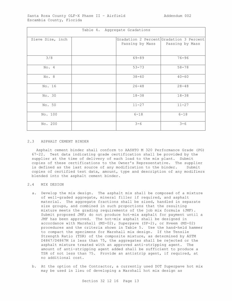
Santa Rosa County OLF-X Phase II – Airfield Addendum 002
Escambia County, Florida
Section 32 12 16 Page 13
Table 4. Aggregate Gradations
Sieve Size, inch Gradation 2 Percent
Passing by Mass
Gradation 3 Percent
Passing by Mass
3/8 69-89 76-96
No. 4 53-73 58-78
No. 8 38-60 40-60
No. 16 26-48 28-48
No. 30 18-38 18-38
No. 50 11-27 11-27
No. 100 6-18 6-18
No. 200 3-6 3-6
2.3 ASPHALT CEMENT BINDER
Asphalt cement binder shall conform to AASHTO M 320 Performance Grade (PG)
67-22. Test data indicating grade certification shall be provided by the
supplier at the time of delivery of each load to the mix plant. Submit
copies of these certifications to the Owner's Representative. The supplier
is defined as the last source of any modification to the binder. Submit
copies of certified test data, amount, type and description of any modifiers
blended into the asphalt cement binder.
2.4 MIX DESIGN
a. Develop the mix design. The asphalt mix shall be composed of a mixture
of well-graded aggregate, mineral filler if required, and asphalt
material. The aggregate fractions shall be sized, handled in separate
size groups, and combined in such proportions that the resulting
mixture meets the grading requirements of the job mix formula (JMF).
Submit proposed JMF; do not produce hot-mix asphalt for payment until a
JMF has been approved. The hot-mix asphalt shall be designed in
accordance with Marshall (MS-02), Superpave (SP-2), or Hveem (MS-02)
procedures and the criteria shown in Table 5. Use the hand-held hammer
to compact the specimens for Marshall mix design. If the Tensile
Strength Ratio (TSR) of the composite mixture, as determined by ASTM
D4867/D4867M is less than 75, the aggregates shall be rejected or the
asphalt mixture treated with an approved anti-stripping agent. The
amount of anti-stripping agent added shall be sufficient to produce a
TSR of not less than 75. Provide an antistrip agent, if required, at
no additional cost.
b. At the option of the Contractor, a currently used DOT Superpave hot mix
may be used in lieu of developing a Marshall hot mix design as
Santa Rosa County OLF-X Phase II – Airfield Addendum 002
Escambia County, Florida
Section 32 12 16 Page 14
described herein. Design the Superpave volumetric mix in accordance
with AI SP-2 and ASTM D6925. The nominal maximum aggregate size (NMAS)
shall be 1/2 inch. Other DOT hot mix design methods (Hveem, etc.) may
be suitable, as determined by the Contracting Officer. The number of
compaction gyrations, Ndes, shall be based on a design traffic of 0.3M
equivalent single axle loads (EASLs).
c. Design Superpave mixes with the number of gyrations specified in Table
5, unless the DOT option is chosen.
2.4.1 JMF Requirements
Submit in writing the job mix formula for approval at least 14 days prior to
the start of the test section including as a minimum:
a. Percent passing each sieve size.
b. Percent of asphalt cement.
c. Percent of each aggregate and mineral filler to be used.
d. Asphalt viscosity grade, penetration grade, or performance grade.
e. Number of blows of hand-held hammer per side of molded specimen. (NA
for Superpave)
f. Number of gyrations of Superpave gyratory compactor, (NA for Marshall
mix design)
g. Laboratory mixing temperature.
h. Lab compaction temperature.
i. Temperature-viscosity relationship of the asphalt cement.
j. Plot of the combined gradation on the 0.45 power gradation chart,
stating the nominal maximum size.
k. Graphical plots of stability (NA for Superpave), flow (NA for
Superpave), air voids, voids in the mineral aggregate, and unit weight
versus asphalt content as shown in AI MS-2.
l. Specific gravity and absorption of each aggregate.
m. Percent natural sand.
n. Percent particles with 2 or more fractured faces (in coarse aggregate).
o. Fine aggregate angularity.
p. Percent flat or elongated particles (in coarse aggregate).
q. Tensile Strength Ratio(TSR).
r. Antistrip agent (if required) and amount.
s. List of all modifiers and amount.
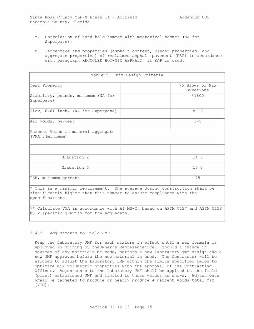
Santa Rosa County OLF-X Phase II – Airfield Addendum 002
Escambia County, Florida
Section 32 12 16 Page 15
t. Correlation of hand-held hammer with mechanical hammer (NA for
Superpave).
u. Percentage and properties (asphalt content, binder properties, and
aggregate properties) of reclaimed asphalt pavement (RAP) in accordance
with paragraph RECYCLED HOT-MIX ASPHALT, if RAP is used.
Table 5. Mix Design Criteria
Test Property 75 Blows or Mix
Gyrations
Stability, pounds, minimum (NA for
Superpave)
*1800
Flow, 0.01 inch, (NA for Superpave) 8-16
Air voids, percent 3-5
Percent Voids in mineral aggregate
(VMA),(minimum)
Gradation 2 14.3
Gradation 3 15.0
TSR, minimum percent 75
* This is a minimum requirement. The average during construction shall be
significantly higher than this number to ensure compliance with the
specifications.
** Calculate VMA in accordance with AI MS-2, based on ASTM C127 and ASTM C128
bulk specific gravity for the aggregate.
2.4.2 Adjustments to Field JMF
Keep the Laboratory JMF for each mixture in effect until a new formula is
approved in writing by theOwner's Representative. Should a change in
sources of any materials be made, perform a new laboratory jmf design and a
new JMF approved before the new material is used. The Contractor will be
allowed to adjust the Laboratory JMF within the limits specified below to
optimize mix volumetric properties with the approval of the Contracting
Officer. Adjustments to the Laboratory JMF shall be applied to the field
(plant) established JMF and limited to those values as shown. Adjustments
shall be targeted to produce or nearly produce 4 percent voids total mix
(VTM).
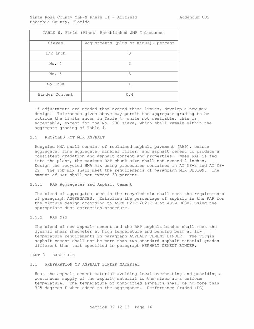
Santa Rosa County OLF-X Phase II – Airfield Addendum 002
Escambia County, Florida
Section 32 12 16 Page 16
TABLE 6. Field (Plant) Established JMF Tolerances
Sieves Adjustments (plus or minus), percent
1/2 inch 3
No. 4 3
No. 8 3
No. 200 1
Binder Content 0.4
If adjustments are needed that exceed these limits, develop a new mix
design. Tolerances given above may permit the aggregate grading to be
outside the limits shown in Table 4; while not desirable, this is
acceptable, except for the No. 200 sieve, which shall remain within the
aggregate grading of Table 4.
2.5 RECYCLED HOT MIX ASPHALT
Recycled HMA shall consist of reclaimed asphalt pavement (RAP), coarse
aggregate, fine aggregate, mineral filler, and asphalt cement to produce a
consistent gradation and asphalt content and properties. When RAP is fed
into the plant, the maximum RAP chunk size shall not exceed 2 inches.
Design the recycled HMA mix using procedures contained in AI MS-2 and AI MS-
22. The job mix shall meet the requirements of paragraph MIX DESIGN. The
amount of RAP shall not exceed 30 percent.
2.5.1 RAP Aggregates and Asphalt Cement
The blend of aggregates used in the recycled mix shall meet the requirements
of paragraph AGGREGATES. Establish the percentage of asphalt in the RAP for
the mixture design according to ASTM D2172/D2172M or ASTM D6307 using the
appropriate dust correction procedure.
2.5.2 RAP Mix
The blend of new asphalt cement and the RAP asphalt binder shall meet the
dynamic shear rheometer at high temperature and bending beam at low
temperature requirements in paragraph ASPHALT CEMENT BINDER. The virgin
asphalt cement shall not be more than two standard asphalt material grades
different than that specified in paragraph ASPHALT CEMENT BINDER.
PART 3 EXECUTION
3.1 PREPARATION OF ASPHALT BINDER MATERIAL
Heat the asphalt cement material avoiding local overheating and providing a
continuous supply of the asphalt material to the mixer at a uniform
temperature. The temperature of unmodified asphalts shall be no more than
325 degrees F when added to the aggregates. Performance-Graded (PG)
Santa Rosa County OLF-X Phase II – Airfield Addendum 002
Escambia County, Florida
Section 32 12 16 Page 17
asphalts shall be within the temperature range of 275 - 325 degrees F when
added to the aggregate.
3.2 PREPARATION OF MINERAL AGGREGATE
Heat and dry the aggregate for the mixture prior to mixing. No damage shall
occur to the aggregates due to the maximum temperature and rate of heating
used. The temperature of the aggregate and mineral filler shall not exceed
350 degrees F when the asphalt cement is added. The temperature shall not
be lower than is required to obtain complete coating and uniform
distribution on the aggregate particles and to provide a mixture of
satisfactory workability.
3.3 PREPARATION OF HOT-MIX ASPHALT MIXTURE
The aggregates and the asphalt cement shall be weighed or metered and
introduced into the mixer in the amount specified by the JMF. Mix the
combined materials until the aggregate obtains a uniform coating of asphalt
binder and is thoroughly distributed throughout the mixture. Wet mixing
time shall be the shortest time that will produce a satisfactory mixture,
but no less than 25 seconds for batch plants. Establish the wet mixing time
for all plants based on the procedure for determining the percentage of
coated particles described in ASTM D2489/D2489M, for each individual plant
and for each type of aggregate used. The wet mixing time will be set to at
least achieve 95 percent of coated particles. The moisture content of all
hot-mix asphalt upon discharge from the plant shall not exceed 0.5 percent
by total weight of mixture as measured by ASTM D1461.
3.4 PREPARATION OF THE UNDERLYING SURFACE
Immediately before placing the hot mix asphalt, clean the underlying course
of dust and debris. Apply a prime coat in accordance with the contract
specifications.
3.5 TESTING LABORATORY
Submit certification of compliance and Plant Scale Calibration
Certification. Use a laboratory to develop the JMF that meets the
requirements of ASTM D3666. The Owner will inspect the laboratory equipment
and test procedures prior to the start of hot mix operations for conformance
to ASTM D3666. The laboratory shall maintain the Corps certification for
the duration of the project. A statement signed by the manager of the
laboratory stating that it meets these requirements or clearly listing all
deficiencies shall be submitted to the Contracting Officer prior to the
start of construction. The statement shall contain as a minimum:
a. Qualifications of personnel; laboratory manager, supervising
technician, and testing technicians.
b. A listing of equipment to be used in developing the job mix.
c. A copy of the laboratory's quality control system.
d. Evidence of participation in the AASHTO Materials Reference Laboratory
(AMRL) program.
Santa Rosa County OLF-X Phase II – Airfield Addendum 002
Escambia County, Florida
Section 32 12 16 Page 18
3.6 TRANSPORTING AND PLACING
3.6.1 Transporting
Transport the hot-mix asphalt from the mixing plant to the site in clean,
tight vehicles. Schedule deliveries so that placing and compacting of
mixture is uniform with minimum stopping and starting of the paver. Provide
adequate artificial lighting for night placements. Hauling over freshly
placed material will not be permitted until the material has been compacted
as specified, and allowed to cool to 140 degrees F. To deliver mix to the
paver, use a material transfer vehicle operated to produce continuous
forward motion of the paver.
3.6.2 Placing
Place and compact the mix at a temperature suitable for obtaining density,
surface smoothness, and other specified requirements. Upon arrival, place
the mixture to the full width by an asphalt paver; it shall be struck off in
a uniform layer of such depth that, when the work is completed, it will have
the required thickness and conform to the grade and contour indicated.
Regulate the speed of the paver to eliminate pulling and tearing of the
asphalt mat. Unless otherwise permitted, placement of the mixture shall
begin along the centerline of a crowned section or on the high side of areas
with a one-way slope. Place the mixture in consecutive adjacent strips
having a minimum width of 10 feet. The longitudinal joint in one course
shall offset the longitudinal joint in the course immediately below by at
least 1 foot; however, the joint in the surface course shall be at the
centerline of the pavement. Transverse joints in one course shall be offset
by at least 10 feet from transverse joints in the previous course.
Transverse joints in adjacent lanes shall be offset a minimum of 10 feet.
On isolated areas where irregularities or unavoidable obstacles make the use
of mechanical spreading and finishing equipment impractical, the mixture may
be spread and luted by hand tools.
3.7 COMPACTION OF MIXTURE
After placing, the mixture shall be thoroughly and uniformly compacted by
rolling. Compact the surface as soon as possible without causing
displacement, cracking or shoving. The sequence of rolling operations and
the type of rollers used shall be at the discretion of the Contractor. The
speed of the roller shall, at all times, be sufficiently slow to avoid
displacement of the hot mixture and be effective in compaction. Any
displacement occurring as a result of reversing the direction of the roller,
or from any other cause, shall be corrected at once. Furnish sufficient
rollers to handle the output of the plant. Continue rolling until the
surface is of uniform texture, true to grade and cross section, and the
required field density is obtained. To prevent adhesion of the mixture to
the roller, keep the wheels properly moistened but excessive water will not
be permitted. In areas not accessible to the roller, the mixture shall be
thoroughly compacted with hand tampers. Any mixture that becomes loose and
broken, mixed with dirt, contains check-cracking, or is in any way defective
shall be removed full depth, replaced with fresh hot mixture and immediately
compacted to conform to the surrounding area. This work shall be done at
the Contractor's expense. Skin patching will not be allowed.
3.8 JOINTS
Santa Rosa County OLF-X Phase II – Airfield Addendum 002
Escambia County, Florida
Section 32 12 16 Page 19
The formation of joints shall be performed ensuring a continuous bond
between the courses and to obtain the required density. All joints shall
have the same texture as other sections of the course and meet the
requirements for smoothness and grade.
3.8.1 Transverse Joints
Do not pass the roller over the unprotected end of the freshly laid mixture,
except when necessary to form a transverse joint. When necessary to form a
transverse joint, it shall be made by means of placing a bulkhead or by
tapering the course. The tapered edge shall be cut back to its full depth
and width on a straight line to expose a vertical face prior to placing
material at the joint. Remove the cutback material from the project. In
both methods, all contact surfaces shall be given a light tack coat of
asphalt material before placing any fresh mixture against the joint.
3.8.2 Longitudinal Joints
Longitudinal joints which are irregular, damaged, uncompacted, cold (less
than 175 degrees F at the time of placing adjacent lanes), or otherwise
defective, shall be cut back a maximum of 3 inches from the top of the
course with a cutting wheel to expose a clean, sound vertical surface for
the full depth of the course. All cutback material shall be removed from
the project. All contact surfaces shall be given a light tack coat of
asphalt material prior to placing any fresh mixture against the joint. The
Contractor will be allowed to use an alternate method if it can be
demonstrated that density, smoothness, and texture can be met.
3.9 QUALITY CONTROL
3.9.1 General Quality Control Requirements
Develop and submit an approved Quality Control Plan. Submit aggregate and
QC test results. Do not produce hot-mix asphalt for payment until the
quality control plan has been approved addressing all elements which affect
the quality of the pavement including, but not limited to:
a. Mix Design
b. Aggregate Grading
c. Quality of Materials
d. Stockpile Management
e. Proportioning
f. Mixing and Transportation
g. Mixture Volumetrics
h. Moisture Content of Mixtures
i. Placing and Finishing
j. Joints
Santa Rosa County OLF-X Phase II – Airfield Addendum 002
Escambia County, Florida
Section 32 12 16 Page 20
k. Compaction
l. Surface Smoothness
3.9.2 Quality Control Testing
Perform all quality control tests applicable to these specifications and as
set forth in the Quality Control Program. The testing program shall
include, but shall not be limited to, tests for the control of asphalt
content, aggregate gradation, temperatures, aggregate moisture, moisture in
the asphalt mixture, laboratory air voids, stability (NA for Superpave),
flow (NA for Superpave), in-place density, grade and smoothness. Develop a
Quality Control Testing Plan as part of the Quality Control Program.
3.9.2.1 Asphalt Content
A minimum of two tests to determine asphalt content will be performed per
lot (a lot is defined in paragraph MATERIAL ACCEPTANCE and PERCENT PAYMENT)
by one of the following methods: the extraction method in accordance with
ASTM D2172/D2172M, Method A or B, the ignition method in accordance with
ASTM D6307, or the nuclear method in accordance with ASTM D4125/D4125M.
Calibrate the ignition oven or the nuclear gauge for the specific mix being
used. For the extraction method, determine the weight of ash, as described
in ASTM D2172/D2172M, as part of the first extraction test performed at the
beginning of plant production; and as part of every tenth extraction test
performed thereafter, for the duration of plant production. The last weight
of ash value obtained shall be used in the calculation of the asphalt
content for the mixture.
3.9.2.2 Gradation
Determine aggregate gradations a minimum of twice per lot from mechanical
analysis of recovered aggregate in accordance with ASTM D5444. When asphalt
content is determined by the ignition oven or nuclear method, aggregate
gradation shall be determined from hot bin samples on batch plants, or from
the cold feed on drum mix plants. For batch plants, test aggregates in
accordance with ASTM C136/C136M using actual batch weights to determine the
combined aggregate gradation of the mixture.
3.9.2.3 Temperatures
Check temperatures at least four times per lot, at necessary locations, to
determine the temperature at the dryer, the asphalt cement in the storage
tank, the asphalt mixture at the plant, and the asphalt mixture at the job
site.
3.9.2.4 Aggregate Moisture
Determine the moisture content of aggregate used for production a minimum of
once per lot in accordance with ASTM C566.
3.9.2.5 Moisture Content of Mixture
Determine the moisture content of the mixture at least once per lot in
accordance with ASTM D1461 or an approved alternate procedure.
Santa Rosa County OLF-X Phase II – Airfield Addendum 002
Escambia County, Florida
Section 32 12 16 Page 21
3.9.2.6 Laboratory Air Voids, Marshall Stability and Flow
Take mixture samples at least four times per lot compacted into specimens,
using 75 blows per side with the hand-held Marshall hammer as described in
ASTM D6926. When the Superpave gyratory compactor is used, mixes will be
compacted to 75 gyrations in accordance with ASTM D6925. Hot-mix provided
under the DOT Superpave option shall be compacted in accordance with the DOT
requirements. After compaction, determine the laboratory air voids of each
specimen. Stability and flow shall be determined for the Marshall-compacted
specimens, in accordance with ASTM D6927.
3.9.2.7 In-Place Density
Conduct any necessary testing to ensure the specified density is achieved.
A nuclear gauge may be used to monitor pavement density in accordance with
ASTM D2950/D2950M.
3.9.2.8 Grade and Smoothness
Conduct the necessary checks to ensure the grade and smoothness requirements
are met in accordance with paragraphs MATERIAL ACCEPTANCE and PERCENT
PAYMENT.
3.9.2.9 Additional Testing
Any additional testing, which the Contractor deems necessary to control the
process, may be performed at the Contractor's option.
3.9.2.10 QC Monitoring
Submit all QC test results to the Owner's Representative on a daily basis as
the tests are performed. The Contracting Officer reserves the right to
monitor any of the Contractor's quality control testing and to perform
duplicate testing as a check to the Contractor's quality control testing.
3.9.3 Sampling
When directed by the Owner's Representative, sample and test any material
which appears inconsistent with similar material being produced, unless such
material is voluntarily removed and replaced or deficiencies corrected by
the Contractor. All sampling shall be in accordance with standard
procedures specified.
3.10 MATERIAL ACCEPTANCE
Testing for acceptability of work will be performed by an independent
laboratory hired by the Contractor. Forward test results and payment
calculations daily to theOwner's Representative. Acceptance of the plant
produced mix and in-place requirements will be on a lot to lot basis. A
standard lot for all requirements will be equal to 8 hours of production.
Where appropriate, adjustment in payment for individual lots of hot-mix
asphalt will be made based on in-place density, laboratory air voids, grade
and smoothness in accordance with the following paragraphs. Grade and
surface smoothness determinations will be made on the lot as a whole.
Exceptions or adjustments to this will be made in situations where the mix
within one lot is placed as part of both the intermediate and surface
courses, thus grade and smoothness measurements for the entire lot cannot be
Santa Rosa County OLF-X Phase II – Airfield Addendum 002
Escambia County, Florida
Section 32 12 16 Page 22
made. In order to evaluate laboratory air voids and in-place (field)
density, each lot will be divided into four equal sublots.
3.10.1 Sublot Sampling
One random mixture sample for determining laboratory air voids, theoretical
maximum density, and for any additional testing the Contracting Officer
desires, will be taken from a loaded truck delivering mixture to each
sublot, or other appropriate location for each sublot. All samples will be
selected randomly, using commonly recognized methods of assuring randomness
conforming to ASTM D3665 and employing tables of random numbers or computer
programs. Laboratory air voids will be determined from three laboratory
compacted specimens of each sublot sample in accordance with ASTM D6926.
The specimens will be compacted within 2 hours of the time the mixture was
loaded into trucks at the asphalt plant. Samples will not be reheated prior
to compaction and insulated containers will be used as necessary to maintain
the temperature.
3.10.2 Additional Sampling and Testing
The Contracting Officer reserves the right to direct additional samples and
tests for any area which appears to deviate from the specification
requirements. The cost of any additional testing will be paid for by the
Owner. Testing in these areas will be in addition to the lot testing, and
the requirements for these areas will be the same as those for a lot.
3.10.3 Grade
The final wearing surface of pavement shall conform to the elevations and
cross sections shown and shall vary not more than 0.05 foot from the plan
grade established and approved at site of work. Finished surfaces at
juncture with other pavements shall coincide with finished surfaces of
abutting pavements. Deviation from the plan elevation will not be permitted
in areas of pavements where closer conformance with planned elevation is
required for the proper functioning of drainage and other appurtenant
structures involved. The grade will be determined by running lines of
levels at intervals of 25 feet, or less, longitudinally and transversely, to
determine the elevation of the completed pavement surface. Within 5 working
days, after the completion of a particular lot incorporating the final
wearing surface, test the final wearing surface of the pavement for
conformance with the specified plan grade. Diamond grinding may be used to
remove high spots to meet grade requirements. Skin patching for correcting
low areas or planing or milling for correcting high areas will not be
permitted.
3.10.4 Surface Smoothness
Use one of the following methods to test and evaluate surface smoothness of
the pavement. Perform all testing in the presence of the Contracting
Officer. Keep detailed notes of the results of the testing and furnish a
copy to the Owner immediately after each day's testing. Use the
profilograph method for all longitudinal testing, except where the runs
would be less than 200 feet in length and the ends where the straightedge
will be used. Where drawings show required deviations from a plane surface
(crowns, drainage inlets, etc.), the surface shall be finished to meet the
approval of the Owner's Representative.
Santa Rosa County OLF-X Phase II – Airfield Addendum 002
Escambia County, Florida
Section 32 12 16 Page 23
3.10.4.1 Smoothness Requirements
3.10.4.1.1 Straightedge Testing
The finished surfaces of the pavements shall have no abrupt change of 1/4
inch or more, and all pavements shall be within the tolerances of 1/4 inch
in both the longitudinal and transverse directions, when tested with an
approved 12 feet straightedge.
3.10.4.1.2 Profilograph Testing
The finished surfaces of the pavements shall have no abrupt change of 1/8
inch or more, and each 0.1 mile segment of each pavement lot shall have a
Profile Index not greater than 9 inches/mile when tested with an approved
California-type profilograph. If the extent of the pavement in either
direction is less than 200 feet, that direction shall be tested by the
straightedge method and shall meet requirements specified above.
3.10.4.2 Testing Method
After the final rolling, but not later than 24 hours after placement, test
the surface of the pavement in each entire lot in such a manner as to reveal
all surface irregularities exceeding the tolerances specified above.
Separate testing of individual sublots is not required. If any pavement
areas are ground, these areas shall be retested immediately after grinding.
Test each lot of the pavement in both a longitudinal and a transverse
direction on parallel lines. Set the transverse lines 15 feet or less
apart, as directed. The longitudinal lines shall be at the centerline of
each paving lane for lanes less than 20 feet wide and at the third points
for lanes 20 feet or wider. Also test other areas having obvious
deviations. Longitudinal testing lines shall be continuous across all
joints.
3.10.4.2.1 Straightedge Testing
Hold the straightedge in contact with the surface and move it ahead one-half
the length of the straightedge for each successive measurement. Determine
the amount of surface irregularity by placing the freestanding (unleveled)
straightedge on the pavement surface and allowing it to rest upon the two
highest spots covered by its length, and measuring the maximum gap between
the straightedge and the pavement surface in the area between these two high
points.
3.10.4.2.2 Profilograph Testing
Perform profilograph testing using approved equipment and procedures
described in CTM 526. The equipment shall utilize electronic recording and
automatic computerized reduction of data to indicate "must-grind" bumps and
the Profile Index for each 0.1 mile segment of each pavement lot. Grade
breaks on parking lots shall be accommodated by breaking the profile segment
into shorter sections and repositioning the blanking band on each segment.
The "blanking band" shall be 0.2 inches wide and the "bump template" shall
span 1 inch with an offset of 0.3 inch. Compute the Profile Index for each
pass of the profilograph in each 0.1 mile segment. The Profile Index for
each segment shall be the average of the Profile Indices for each pass in
each segment. The profilograph shall be operated by a DOT approved

Santa Rosa County OLF-X Phase II – Airfield Addendum 002
Escambia County, Florida
Section 32 12 16 Page 24
operator. Furnish a copy of the reduced tapes to the Owner at the end of
each day's testing.
-- End of Section --
Santa Rosa County OLF-X Phase II – Airfield Addendum 002
Escambia County, Florida
Section 32 13 14.13 Page 1
SECTION 32 13 14.13
CONCRETE PAVING FOR AIRFIELDS AND OTHER HEAVY DUTY PAVEMENTS
PART 1 GENERAL
1.1 UNIT PRICES
1.1.1 Measurements
The quantity of concrete to be paid for will be the volume of concrete in
cubic yards including thickened edges , where required, placed in the
completed and accepted pavement. Concrete will be measured in place in the
completed and accepted pavement only within the neat line dimensions shown
in the plan and cross section. No deductions will be made for rounded or
beveled edges or the space occupied by pavement reinforcement, dowel bars,
tie bars, or electrical conduits, nor for any void, or other structure
extending into or through the pavement slab, measuring 3 cubic feet or less
in volume. No other allowance for concrete will be made unless placed in
specified locations in accordance with the approved contract modification.
The quantity of other materials specified herein, and used in the
construction of the work covered by this section, will not be measured for
payment, but will be considered a subsidiary obligation, covered under the
price per cubic yard for concrete. Joint sealing materials are covered in
Section 32 01 19 FIELD MOLDED SEALANTS FOR SEALING JOINTS IN RIGID
PAVEMENTS.
1.1.2 Payments
1.1.2.1 Unit Price
The quantity of concrete measured as specified above will be paid for at the
contract unit price when placed in completed and accepted pavements.
Payment will be made at the contract price for cubic yard for the scheduled
item, with necessary adjustments as specified below. Payment will
constitute full compensation for providing all materials, equipment, plant
and tools, and for all labor and other incidentals necessary to complete the
concrete pavement, except for other items specified herein for separate
payment.
1.1.3 Payment of Lots
When a lot of material fails to meet the specification requirements, that
lot will be accepted at a reduced price or be removed and replaced. The
lowest computed percent payment determined for any pavement characteristic
discussed below (for example, thickness, grade, and surface smoothness)
becomes the actual percent payment for that lot. The actual percent payment
will be applied to the unit price and the measured quantity of concrete in
the lot to determine actual payment. Use results of strength tests to
control concreting operations. Strength will be evaluated, but will not be
considered for payment adjustment. Remove and replace any pavement not
meeting the required 'Concrete Strength for Final Acceptance' at no
additional cost to the Owner.
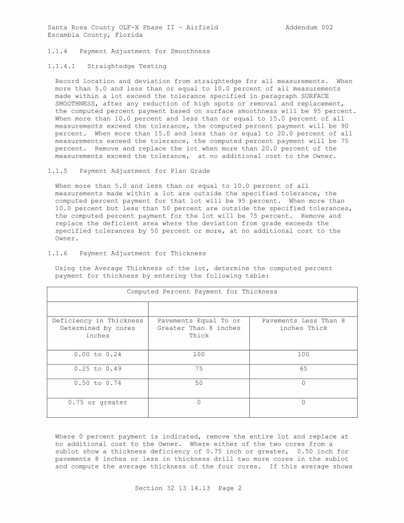
Santa Rosa County OLF-X Phase II – Airfield Addendum 002
Escambia County, Florida
Section 32 13 14.13 Page 2
1.1.4 Payment Adjustment for Smoothness
1.1.4.1 Straightedge Testing
Record location and deviation from straightedge for all measurements. When
more than 5.0 and less than or equal to 10.0 percent of all measurements
made within a lot exceed the tolerance specified in paragraph SURFACE
SMOOTHNESS, after any reduction of high spots or removal and replacement,
the computed percent payment based on surface smoothness will be 95 percent.
When more than 10.0 percent and less than or equal to 15.0 percent of all
measurements exceed the tolerance, the computed percent payment will be 90
percent. When more than 15.0 and less than or equal to 20.0 percent of all
measurements exceed the tolerance, the computed percent payment will be 75
percent. Remove and replace the lot when more than 20.0 percent of the
measurements exceed the tolerance, at no additional cost to the Owner.
1.1.5 Payment Adjustment for Plan Grade
When more than 5.0 and less than or equal to 10.0 percent of all
measurements made within a lot are outside the specified tolerance, the
computed percent payment for that lot will be 95 percent. When more than
10.0 percent but less than 50 percent are outside the specified tolerances,
the computed percent payment for the lot will be 75 percent. Remove and
replace the deficient area where the deviation from grade exceeds the
specified tolerances by 50 percent or more, at no additional cost to the
Owner.
1.1.6 Payment Adjustment for Thickness
Using the Average Thickness of the lot, determine the computed percent
payment for thickness by entering the following table:
Computed Percent Payment for Thickness
Deficiency in Thickness
Determined by cores
inches
Pavements Equal To or
Greater Than 8 inches
Thick
Pavements Less Than 8
inches Thick
0.00 to 0.24 100 100
0.25 to 0.49 75 65
0.50 to 0.74 50 0
0.75 or greater 0 0
Where 0 percent payment is indicated, remove the entire lot and replace at
no additional cost to the Owner. Where either of the two cores from a
sublot show a thickness deficiency of 0.75 inch or greater, 0.50 inch for
pavements 8 inches or less in thickness drill two more cores in the sublot
and compute the average thickness of the four cores. If this average shows
Santa Rosa County OLF-X Phase II – Airfield Addendum 002
Escambia County, Florida
Section 32 13 14.13 Page 3
a thickness deficiency of 0.75 inch or more 0.50 inch for pavements 8 inches
or less in thickness remove the entire sublot.
1.2 REFERENCES
The publications listed below form a part of this specification to the
extent referenced. The publications are referred to within the text by the
basic designation only.
AMERICAN ASSOCIATION OF STATE HIGHWAY AND TRANSPORTATION OFFICIALS
(AASHTO)
AASHTO M 182 (2005; R 2017) Standard Specification for
Burlap Cloth Made from Jute or Kenaf and
Cotton Mats
AMERICAN CONCRETE INSTITUTE INTERNATIONAL (ACI)
ACI 211.1 (1991; R 2009) Standard Practice for
Selecting Proportions for Normal, Heavyweight
and Mass Concrete
ACI 214R (2011) Evaluation of Strength Test Results of
Concrete
ACI 305R (2010) Guide to Hot Weather Concreting
ACI 306R (2016) Guide to Cold Weather Concreting
ASTM INTERNATIONAL (ASTM)
ASTM A1064/A1064M (2017) Standard Specification for Carbon-
Steel Wire and Welded Wire Reinforcement,
Plain and Deformed, for Concrete
ASTM A184/A184M (2017) Standard Specification for Welded
Deformed Steel Bar Mats for Concrete
Reinforcement
ASTM A185/A185M (2007) Standard Specification for Steel
Welded Wire Reinforcement, Plain, for
Concrete
ASTM A615/A615M (2016) Standard Specification for Deformed
and Plain Carbon-Steel Bars for Concrete
Reinforcement
ASTM A775/A775M (2016) Standard Specification for Epoxy-
Coated Steel Reinforcing Bars
ASTM A996/A996M (2016) Standard Specification for Rail-Steel
and Axle-Steel Deformed Bars for Concrete
Reinforcement
ASTM C1017/C1017M (2013; E 2015) Standard Specification for
Chemical Admixtures for Use in Producing
Flowing Concrete
Santa Rosa County OLF-X Phase II – Airfield Addendum 002
Escambia County, Florida
Section 32 13 14.13 Page 4
ASTM C1064/C1064M (2011) Standard Test Method for Temperature
of Freshly Mixed Hydraulic-Cement Concrete
ASTM C117 (2017) Standard Test Method for Materials
Finer than 75-um (No. 200) Sieve in Mineral
Aggregates by Washing
ASTM C123/C123M (2014) Standard Test Method for Lightweight
Particles in Aggregate
ASTM C1260 (2014) Standard Test Method for Potential
Alkali Reactivity of Aggregates (Mortar-Bar
Method)
ASTM C131/C131M (2014) Standard Test Method for Resistance to
Degradation of Small-Size Coarse Aggregate by
Abrasion and Impact in the Los Angeles
Machine
ASTM C136/C136M (2014) Standard Test Method for Sieve
Analysis of Fine and Coarse Aggregates
ASTM C138/C138M (2017a) Standard Test Method for Density
(Unit Weight), Yield, and Air Content
(Gravimetric) of Concrete
ASTM C142/C142M (2017) Standard Test Method for Clay Lumps
and Friable Particles in Aggregates
ASTM C143/C143M (2015) Standard Test Method for Slump of
Hydraulic-Cement Concrete
ASTM C150/C150M (2017) Standard Specification for Portland
Cement
ASTM C1567 (2013) Standard Test Method for Potential
Alkali-Silica Reactivity of Combinations of
Cementitious Materials and Aggregate
(Accelerated Mortar-Bar Method)
ASTM C1602/C1602M (2012) Standard Specification for Mixing
Water Used in Production of Hydraulic Cement
Concrete
ASTM C172/C172M (2014a) Standard Practice for Sampling
Freshly Mixed Concrete
ASTM C174/C174M (2017) Standard Test Method for Measuring
Thickness of Concrete Elements Using Drilled
Concrete Cores
ASTM C231/C231M (2017a) Standard Test Method for Air Content
of Freshly Mixed Concrete by the Pressure
Method
Santa Rosa County OLF-X Phase II – Airfield Addendum 002
Escambia County, Florida
Section 32 13 14.13 Page 5
ASTM C260/C260M (2010a; R 2016) Standard Specification for
Air-Entraining Admixtures for Concrete
ASTM C294 (2012; R 2017) Standard Descriptive
Nomenclature for Constituents of Concrete
Aggregates
ASTM C295/C295M (2012) Petrographic Examination of Aggregates
for Concrete
ASTM C31/C31M (2017) Standard Practice for Making and
Curing Concrete Test Specimens in the Field
ASTM C33/C33M (2016) Standard Specification for Concrete
Aggregates
ASTM C494/C494M (2017) Standard Specification for Chemical
Admixtures for Concrete
ASTM C595/C595M (2017) Standard Specification for Blended
Hydraulic Cements
ASTM C618 (2012a) Standard Specification for Coal Fly
Ash and Raw or Calcined Natural Pozzolan for
Use in Concrete
ASTM C88 (2013) Standard Test Method for Soundness of
Aggregates by Use of Sodium Sulfate or
Magnesium Sulfate
ASTM C881/C881M (2015) Standard Specification for Epoxy-
Resin-Base Bonding Systems for Concrete
ASTM C94/C94M (2017a) Standard Specification for Ready-
Mixed Concrete
ASTM C989/C989M (2017) Standard Specification for Slag Cement
for Use in Concrete and Mortars
ASTM D1751 (2004; E 2013; R 2013) Standard Specification
for Preformed Expansion Joint Filler for
Concrete Paving and Structural Construction
(Nonextruding and Resilient Bituminous Types)
ASTM D1752 (2004a; R 2013) Standard Specification for
Preformed Sponge Rubber Cork and Recycled PVC
Expansion
ASTM D2995 (1999; R 2009) Determining Application Rate
of Bituminous Distributors
ASTM D3665 (2012) Random Sampling of Construction
Materials
ASTM D4791 (2010) Flat Particles, Elongated Particles,
or Flat and Elongated Particles in Coarse
Aggregate
Santa Rosa County OLF-X Phase II – Airfield Addendum 002
Escambia County, Florida
Section 32 13 14.13 Page 6
ASTM D75/D75M (2014) Standard Practice for Sampling
Aggregates
NATIONAL READY MIXED CONCRETE ASSOCIATION (NRMCA)
NRMCA QC 3 (2011) Quality Control Manual: Section 3,
Plant Certifications Checklist: Certification
of Ready Mixed Concrete Production Facilities
U.S. AIR FORCE (USAF)
AF ETL 97-5 (1997) Proportioning Concrete Mixtures with
Graded Aggregates for Rigid Airfield
Pavements
U.S. ARMY CORPS OF ENGINEERS (USACE)
COE CRD-C 130 (2001) Standard Recommended Practice for
Estimating Scratch Hardness of Coarse
Aggregate Particles
COE CRD-C 300 (1990) Specifications for Membrane-Forming
Compounds for Curing Concrete
COE CRD-C 521 (1981) Standard Test Method for Frequency and
Amplitude of Vibrators for Concrete
COE CRD-C 55 (1992) Test Method for Within-Batch
Uniformity of Freshly Mixed Concrete
COE CRD-C 662 (2009) Determining the Potential Alkali-
Silica Reactivity of Combinations of
Cementitious Materials, Lithium Nitrate
Admixture and Aggregate (Accelerated Mortar-
Bar Method)
1.3 SUBMITTALS
Owner approval is required for submittals with a "G" designation; submittals
not having a "G" designation are for information only. Submit the following
in accordance with Section 01 33 00 SUBMITTAL PROCEDURES:
SD-03 Product Data
Diamond Grinding Plan; G
Dowels; G
Dowel Bar Assemblies; G
Equipment
Proposed Techniques; G
SD-05 Design Data
Santa Rosa County OLF-X Phase II – Airfield Addendum 002
Escambia County, Florida
Section 32 13 14.13 Page 7
Preliminary Proposed Proportioning; G
Proportioning Studies; G
SD-06 Test Reports
Batch Plant Manufacturer's Inspection Report; G
Slipform Paver Manufacturer's Inspection Report; G
Sampling and Testing; G
Diamond Grinding of PCC Surfaces; G
Mixer Performance (Uniformity) Testing; G
Repair Recommendations Plan; G
SD-07 Certificates
Contractor Quality Control Staff; G
Laboratory Accreditation and Validation
NRMCA Certificate of Conformance
1.4 QUALITY CONTROL
1.4.1 Contractor Quality Control Staff
Reference Section 01 45 00.00 20 QUALITY CONTROL for Contractor personnel
qualification requirements. Submit American Concrete Institute
certification for Contractor Quality Control staff. Qualifications and
resumes for petrographer, surveyor, concrete batch plant operator, and
profilograph operator. All Contractor Quality Control personnel assigned to
concrete construction are required to be American Concrete Institute (ACI)
certified in the following grade:
a. The minimum requirements for the CQC System Manager consist of being a
graduate engineer or a graduate of construction management, with a
minimum of 5 years airfield construction experience and a minimum of 1
year experience as a CQC System Manager on an airfield construction
project.
b. CQC personnel responsible for inspection of concrete paving operations:
ACI Concrete Transportation Inspector. The ACI Concrete Transportation
Inspector is required to be present at the paving site during all
paving operations, with the exception of the initial saw cutting
operation. The QC manager is required to be present during initial saw
cutting operations.
c. CQC staff is required to oversee all aspects of sawing operations
(sawing, flushing, vacuuming, checking for random cracking, lighting).
d. Lead Foreman or Journeyman of the Concrete Placing, Finishing, and
Curing Crews: ACI Concrete Flatwork Technician/Finisher.
Santa Rosa County OLF-X Phase II – Airfield Addendum 002
Escambia County, Florida
Section 32 13 14.13 Page 8
e. Batch Plant Manufacturer's Representative: A representative from the
batch plant manufacturer is required to be on-site to inspect and make
necessary adjustments to all components of the batch plant including
but not limited to aggregate bin weighing operations, water metering,
cement and fly ash weighing devices. All necessary inspections and
adjustments by the manufacturer representative is required to be
performed prior to uniformity testing. Submit a written Batch Plant
Manufacturer's Inspection Report signed by the representative noting
all inspection items and corrections and stating the batch plant is
capable of producing the volume of concrete as required herein.
f. Field Testing Technicians: ACI Concrete Field Testing Technician, Grade
I.
g. Slipform Paving Equipment Manufacturer's Representative: A
representative of the slipform paving equipment manufacturer is
required to be on-site to inspect and make corrections to the paving
equipment to ensure proper operations. Perform a complete and full
hydraulic flow test of the vibrator system prior to the test section
being placed. Submit a written Slipform Paver Manufacturer's
Inspection Report signed by the manufacturer's representative noting
all inspections, corrections, and flow tests have been performed and
the paver is in a condition to perform the required work.
h. Laboratory Testing Technicians: ACI Concrete Strength Testing
Technician and Laboratory Testing Technician, Grade I or II.
1.4.2 Other Staff
Submit for approval, the qualifications and resumes for the following staff:
a. Petrographer: Bachelor of Science degree in geology or petrography,
trained in petrographic examination of concrete aggregate according to
ASTM C294 and ASTM C295/C295M and trained in identification of the
specific deleterious materials and tests identified in this
specification. Detail the education, training and experience related
to the project-specific test methods and deleterious materials in the
Resume and submit at least 20 days before petrographic and deleterious
materials examination is to commence.
b. Licensed Surveyor: Perform all survey work under the supervision of a
Licensed Surveyor.
c. Concrete Batch Plant Operator: National Ready Mix Concrete Association
(NRMCA) Plant Manager certification.
1.4.3 Preconstruction Testing of Materials
All sampling and testing is required to be performed. Use an approved
commercial laboratory or, for cementitious materials and chemical
admixtures, a laboratory maintained by the manufacturer of the material.
Materials are not allowed to be used until notice of acceptance has been
given. Additional payment or extension of time due to failure of any
material to meet project requirements, or for any additional sampling or
testing required is not allowed. Additional tests may be performed by the
Owner; such Owner testing does not relieve any required testing
responsibilities.
Santa Rosa County OLF-X Phase II – Airfield Addendum 002
Escambia County, Florida
Section 32 13 14.13 Page 9
1.4.3.1 Aggregates
Sample aggregates in the presence of a Owner's Representative. Obtain
samples in accordance with ASTM D75/D75M and be representative of the
materials to be used for the project. Perform all aggregate tests no
earlier than 120 days prior to contract award. Submit test results a
minimum of 7 days before commencing mixture proportioning studies.
1.4.3.2 Chemical Admixtures, Curing Compounds and Epoxies
At least 30 days before the material is used, submit certified copies of
test results for the specific lots or batches to be used on the project.
Provide test results less than 6 months old prior to use in the work.
Retest chemical admixtures that have been in storage at the project site for
longer than 6 months or that have been subjected to freezing, and rejected
if test results do not meet manufacturer requirements.
1.4.3.3 Cementitious Materials
Cement, slag cement, and pozzolan will be accepted on the basis of
manufacturer's certification of compliance, accompanied by mill test reports
showing that the material in each shipment meets the requirements of the
specification under which it is provided. Provide mill test reports no more
than 1 month old, prior to use in the work. Do not use cementitious
materials until notice of acceptance has been given. Cementitious materials
may be subjected to testing by the Owner from samples obtained at the mill,
at transfer points, or at the project site. If tests prove that a
cementitious material that has been delivered is unsatisfactory, promptly
remove it from the project site. Retest cementitious material that has not
been used within 6 months after testing, and reject if test results do not
meet manufacturer requirements.
1.4.4 Testing During Construction
During construction, sample and test aggregates, cementitious materials, and
concrete as specified herein. The Owner will sample and test concrete and
ingredient materials as considered appropriate. Provide facilities and
labor as may be necessary for procurement of representative test samples.
Testing by the Owner does not relieve the specified testing requirements.
1.4.5 Acceptability of Work
The materials and the pavement itself will be accepted on the basis of
production testing. The Owner may make check tests to validate the results
of the production testing. If the results of the production testing vary by
less than 2.0 percent of the Owner's test results, the results of the
production testing will be used. If the results of the Owner and production
tests vary by 2.0 percent, but less than 4.0 percent, the average of the two
will be considered the value to be used. If these vary by 4.0 percent or
more, carefully evaluate each sampling and testing procedure and obtain
another series of Owner and production tests on duplicate samples of
material. If these vary by 4.0 percent or more, use the results of the
tests made by the Owner and the Owner will continue check testing of this
item on a continuous basis until the two sets of tests agree within less
than 4.0 percent on a regular basis. Testing performed by the Owner does
not relieve the specified testing requirements.
Santa Rosa County OLF-X Phase II – Airfield Addendum 002
Escambia County, Florida
Section 32 13 14.13 Page 10
1.4.6 Acceptance Requirements
1.4.6.1 Pavement Lots
A lot is that quantity of construction to be evaluated for acceptance with
specification requirements. A lot is equal to one shift of production not
to exceed 1000 cubic yards. In order to evaluate thickness, divide each lot
into four equal sublots. A sublot is equal to one shift of production not
to exceed 250 cubic yards. Grade determinations will be made on the lot as
a whole. Surface smoothness determinations will be made on every 0.1 mile
segment in each lot. Select sample locations on a random basis in
accordance with ASTM D3665. When operational conditions cause a lot to be
terminated before the specified four sublots have been completed, use the
following procedure to adjust the lot size and number of tests for the lot.
Where three sublots have been completed, they constitute a lot. Where one
or two sublots have been completed, incorporate them into the next lot
(except for the last lot), and the total number of sublots used and
acceptance criteria adjusted accordingly.
1.4.6.2 Evaluation
Provide all sampling and testing required for acceptance and payment
adjustment, including batch tickets with all required acceptance testing.
Individuals performing sampling, testing and inspection duties are required
to meet the Qualifications. The Owner reserves the right to direct
additional samples and tests for any area which appears to deviate from the
specification requirements. Testing in these areas are in addition to the
sublot or lot testing, and the requirements for these areas are the same as
those for a sublot or lot. Provide facilities for and, where directed,
personnel to assist in obtaining samples for any Owner testing.
1.5 DELIVERY, STORAGE, AND HANDLING
1.5.1 Bulk Cementitious Materials
Provide all cementitious materials in bulk at a temperature, as delivered to
storage at the site, not exceeding 150 degrees F. Provide sufficient
cementitious materials in storage to sustain continuous operation of the
concrete mixing plant while the pavement is being placed. Provide separate
facilities to prevent any intermixing during unloading, transporting,
storing, and handling of each type of cementitious material.
1.5.2 Aggregate Materials
Store aggregate at the site of the batching and mixing plant avoiding
breakage, segregation, intermixing or contamination by foreign materials.
Store each size of aggregate from each source separately in free-draining
stockpiles. Provide a minimum 24 inch thick sacrificial layer left
undisturbed for each aggregate stored on ground. Provide free-draining
storage for fine aggregate and the smallest size coarse aggregate for at
least 24 hours immediately prior to use. Maintain sufficient aggregate at
the site at all times to permit continuous uninterrupted operation of the
mixing plant at the time concrete pavement is being placed. Do not allow
tracked equipment on coarse aggregate stockpiles.
Santa Rosa County OLF-X Phase II – Airfield Addendum 002
Escambia County, Florida
Section 32 13 14.13 Page 11
1.5.3 Other Materials
Store reinforcing bars and accessories above the ground on supports. Store
all materials to avoid contamination and deterioration.
PART 2 PRODUCTS
2.1 SYSTEM DESCRIPTION
This section is intended to stand alone for construction of concrete
pavement. However, where the construction covered herein interfaces with
other sections, construct each interface to conform to the requirements of
both this section and the other section, including tolerances for both.
2.1.1 Surface Smoothness
Use the straightedge method for transverse testing, for longitudinal testing
where the length of each pavement lane is less than 200 feet, and at the
ends of the paving limits for the project. Smoothness requirements do not
apply over crowns, drainage structures, or similar penetration. Maintain
detailed notes of the testing results and provide a copy to the Owner after
each day's testing.
2.1.1.1 Straightedge Testing
Provide the finished surfaces of the pavements with no abrupt change of 1/4
inch or more, and all pavements within the limits specified when checked
with an approved 12 foot straightedge. Provide all other airfield areas
with a variation from a straight edge not greater than 1/4 inch in either
the longitudinal or transverse direction.
2.1.1.2 Testing Method
After the concrete has hardened sufficiently to permit walking thereon, but
not later than 48 hours after placement, test the entire surface of the
pavement in each lot in such a manner as to reveal all surface
irregularities exceeding the tolerances specified above. If any pavement
areas are diamond ground, retest these areas immediately after diamond
grinding. Test the entire area of the pavement in both a longitudinal and a
transverse direction on parallel lines. Perform the transverse lines 15
feet or less apart, as directed. Perform the longitudinal lines at the
centerline of each paving lane shown on the drawings, regardless of whether
multiple lanes are allowed to be paved at the same time, and at the 1/8th
point in from each side of the lane. Also test other areas having obvious
deviations. Perform longitudinal testing lines continuous across all
joints. Perform transverse testing lines for pilot lanes carried to
construction joint lines and for fill-in lanes carried 24 inches across
construction joints, and the readings in this area applied to the fill-in
lane. Perform straightedge testing of the longitudinal edges of slipformed
pilot lanes before paving fill-in lanes as specified below.
2.1.1.2.1 Straightedge Testing
Hold the straightedge in contact with the surface and moved ahead one-half
the length of the straightedge for each successive measurement. Determine
the amount of surface irregularity by placing the freestanding (unleveled)
straightedge on the pavement surface and measuring the maximum gap between

Santa Rosa County OLF-X Phase II – Airfield Addendum 002
Escambia County, Florida
Section 32 13 14.13 Page 12
the straightedge and the pavement surface. Determine measurements along the
entire length of the straight edge.
2.1.2 Edge Slump and Joint Face Deformation
2.1.2.1 Edge Slump
When slip-form paving is used, provide a maximum of 15.0 percent of the
total free edge of each pavement panel with a maximum edge slump of 1/4 inch
and none of the free edge of the pavement lot with an edge slump exceeding
3/8 inch. (A pavement panel is defined as a lane width by the length
between two adjacent transverse contraction joints. The total free edge of
the pavement is the cumulative total linear measurement of pavement panel
edge originally constructed as non-adjacent to any existing pavement; for
example, 100 feet of pilot lane originally constructed as a separate lane,
would have 200 feet of free edge; 100 feet of fill-in lane would have no
free edge). The area affected by the downward movement of the concrete
along the pavement edge is a maximum of 18 inches back from the edge.
2.1.2.2 Joint Face Deformation
In addition to the edge slump limits specified above, provide a vertical
joint face with a surface within the maximum limits shown below:
Offset from
Straightedge
Applied
Longitudinally
to Pavement
Surface (a)
Offset from
Straightedge
Applied
Longitudinally
to Vertical
Face (b)
Offset from
Straightedge
Applied Top to
Bottom Against
the Joint Face
(c)
Abrupt Offset
in Any
Direction (d)
Offset of Joint
Face from True
Vertical (e)
Airfield Pavement
1/8 inch 1/4 inch 3/8 inch 1/8 inch 1 inch per 12
inches
All Other Pavement
1/4 inch All other items same as airfield pavement
(a) Measurement is taken by placing the straightedge longitudinally on the
pavement surface 1 inch from the free edge.
(b) Measurement is taken by applying the straightedge longitudinally along
the vertical joint face.
(c) Measurement places a 3/8 inch spacer attached to a straightedge and
spaced approximately equal to the thickness of the concrete being measured.
The offset from straightedge with spacers is measured by placing the spacers
against the top and bottom of the vertical concrete face.
(d) An abrupt offset in the joint face occurring along a short distance.
Check for abrupt offsets at any location that an abrupt offset appears to be
a possible issue.
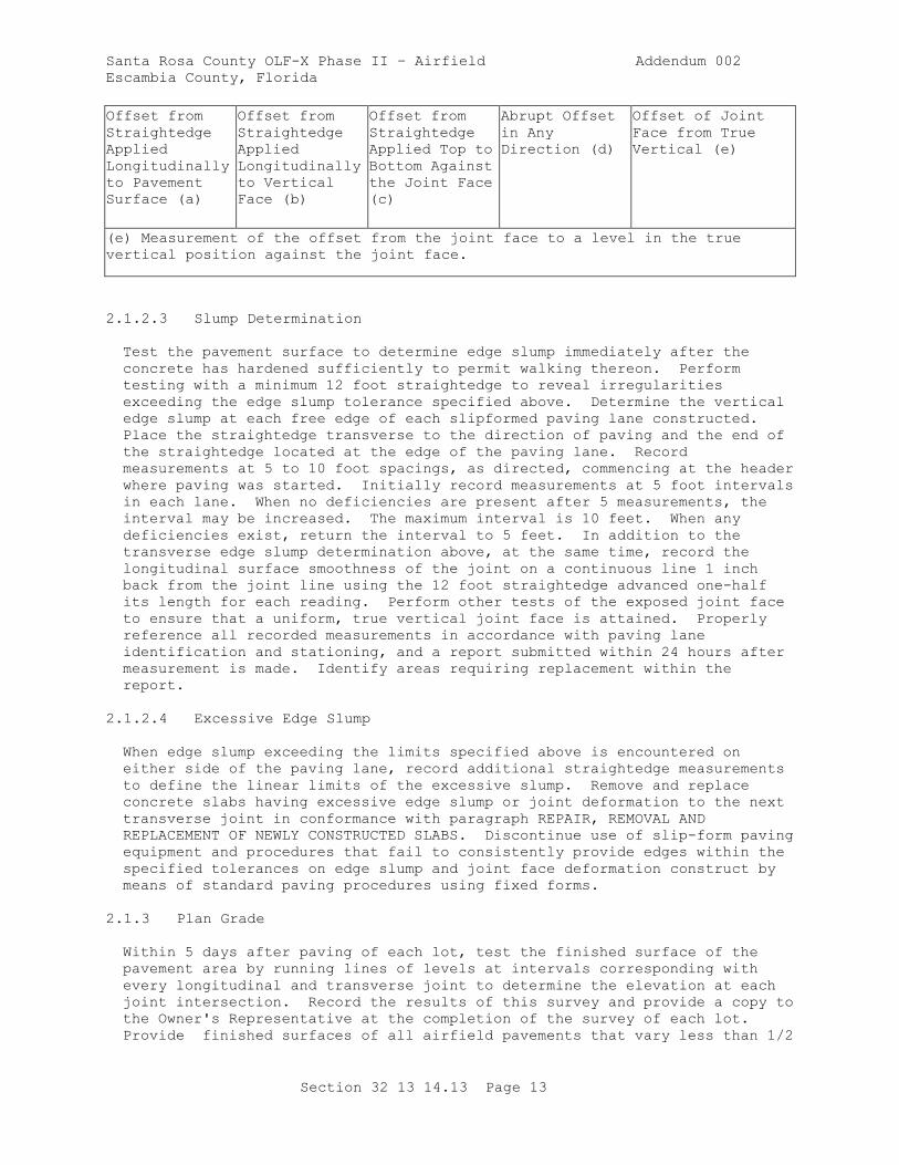
Santa Rosa County OLF-X Phase II – Airfield Addendum 002
Escambia County, Florida
Section 32 13 14.13 Page 13
Offset from
Straightedge
Applied
Longitudinally
to Pavement
Surface (a)
Offset from
Straightedge
Applied
Longitudinally
to Vertical
Face (b)
Offset from
Straightedge
Applied Top to
Bottom Against
the Joint Face
(c)
Abrupt Offset
in Any
Direction (d)
Offset of Joint
Face from True
Vertical (e)
(e) Measurement of the offset from the joint face to a level in the true
vertical position against the joint face.
2.1.2.3 Slump Determination
Test the pavement surface to determine edge slump immediately after the
concrete has hardened sufficiently to permit walking thereon. Perform
testing with a minimum 12 foot straightedge to reveal irregularities
exceeding the edge slump tolerance specified above. Determine the vertical
edge slump at each free edge of each slipformed paving lane constructed.
Place the straightedge transverse to the direction of paving and the end of
the straightedge located at the edge of the paving lane. Record
measurements at 5 to 10 foot spacings, as directed, commencing at the header
where paving was started. Initially record measurements at 5 foot intervals
in each lane. When no deficiencies are present after 5 measurements, the
interval may be increased. The maximum interval is 10 feet. When any
deficiencies exist, return the interval to 5 feet. In addition to the
transverse edge slump determination above, at the same time, record the
longitudinal surface smoothness of the joint on a continuous line 1 inch
back from the joint line using the 12 foot straightedge advanced one-half
its length for each reading. Perform other tests of the exposed joint face
to ensure that a uniform, true vertical joint face is attained. Properly
reference all recorded measurements in accordance with paving lane
identification and stationing, and a report submitted within 24 hours after
measurement is made. Identify areas requiring replacement within the
report.
2.1.2.4 Excessive Edge Slump
When edge slump exceeding the limits specified above is encountered on
either side of the paving lane, record additional straightedge measurements
to define the linear limits of the excessive slump. Remove and replace
concrete slabs having excessive edge slump or joint deformation to the next
transverse joint in conformance with paragraph REPAIR, REMOVAL AND
REPLACEMENT OF NEWLY CONSTRUCTED SLABS. Discontinue use of slip-form paving
equipment and procedures that fail to consistently provide edges within the
specified tolerances on edge slump and joint face deformation construct by
means of standard paving procedures using fixed forms.
2.1.3 Plan Grade
Within 5 days after paving of each lot, test the finished surface of the
pavement area by running lines of levels at intervals corresponding with
every longitudinal and transverse joint to determine the elevation at each
joint intersection. Record the results of this survey and provide a copy to
the Owner's Representative at the completion of the survey of each lot.
Provide finished surfaces of all airfield pavements that vary less than 1/2
Santa Rosa County OLF-X Phase II – Airfield Addendum 002
Escambia County, Florida
Section 32 13 14.13 Page 14
inch above or below the plan grade line or elevation indicated. The above
deviations from the approved grade line and elevation are not permitted in
areas where closer conformance with the planned grade and elevation is
required for the proper functioning of appurtenant structures. Provide
finished surfaces of new abutting pavements that coincide at their juncture.
Provide horizontal control of the finished surfaces of all airfield
pavements that vary not more than 1/2 inch from the plan alignment
indicated.
2.1.4 Flexural Strength
Submit certified copies of laboratory test reports and sources for cement,
supplementary cementitious materials (SCM), aggregates, admixtures, curing
compound, epoxy, and proprietary patching materials proposed for use on this
project. Each lot of pavement will be evaluated for acceptance in
accordance with the following procedures.
2.1.4.1 Sampling and Testing
For acceptance, obtain one composite sample of concrete from each sublot in
accordance with ASTM C172/C172M from one batch or truckload.
2.1.4.2 Computations
Average the eight 14-day strength tests for the lot. Use the average
strength in accordance with paragraph CONCRETE STRENGTH FOR FINAL ACCEPTANCE
in PART 2.
2.1.5 Thickness
Each lot of pavement will be evaluated for acceptance and payment adjustment
in accordance with the following procedure. Drill two cores, between 4 and
6 inches in diameter, from the pavement, per sublot (8 per lot). Drill the
cores within 3 days after lot placement, filling the core holes with an
approved non-shrink concrete, respraying the cored areas with curing
compound, and for measuring the cores. Provide the results with the
thickness measurement data. Record eight measurements of thickness around
the circumference of each core and one in the center, in accordance with
ASTM C174/C174M. Average the pavement thickness from the 8 cores for the
lot and evaluate as described in paragraph PAYMENT ADJUSTMENT FOR THICKNESS
above.
2.1.6 Evaluation of Cores
Record and submit testing, inspection, and evaluation of each core for
surface paste, uniformity of aggregate distribution, segregation, voids,
cracks, and depth of reinforcement or dowel (if present). Moisten the core
with water to visibly expose the aggregate and take a minimum of three
photographs of the sides of the core, rotating the core approximately 120
degrees between photographs. Include a ruler for scale in the photographs.
Provide plan view of location for each core.
2.1.7 Diamond Grinding of PCC Surfaces
Those performing diamond grinding are required to have a minimum of three
years experience in diamond grinding of airfield pavements. In areas not
meeting the specified limits for surface smoothness and plan grade, reduce
Santa Rosa County OLF-X Phase II – Airfield Addendum 002
Escambia County, Florida
Section 32 13 14.13 Page 15
high areas to attain the required smoothness and grade, except as depth is
limited below. Reduce high areas by diamond grinding the hardened concrete
with an approved equipment after the concrete is at a minimum age of 14
days. Perform diamond grinding by sawing with an industrial diamond
abrasive which is impregnated in the saw blades. Assemble the saw blades in
a cutting head mounted on a machine designed specifically for diamond
grinding that produces the required texture and smoothness level without
damage to the concrete pavement or joint faces. Provide diamond grinding
equipment with saw blades that are 1/8-inch wide, a minimum of 60 blades per
12 inches of cutting head width, and capable of cutting a path a minimum of
3 ft wide. Diamond grinding equipment that causes ravels, aggregate
fractures, spalls or disturbance to the joints is not permitted. The
maximum area corrected by diamond grinding the surface of the hardened
concrete is 10 percent of the total area of any sublot. The maximum depth
of diamond grinding is 1/4 inch. Provide diamond grinding machine equipped
to flush and vacuum the pavement surface. Dispose of all debris from
diamond grinding operations off Owner property. Prior to diamond grinding,
submit a Diamond Grinding Plan for review and approval. At a minimum,
include the daily reports for the deficient areas, the location and extent
of deficiencies, corrective actions, and equipment. Remove and replace all
pavement areas requiring plan grade or surface smoothness corrections in
excess of the limits specified above in conformance with paragraph REPAIR,
REMOVAL AND REPLACEMENT OF NEWLY CONSTRUCTED SLABS. All areas in which
diamond grinding has been performed are subject to the thickness tolerances
specified in paragraph THICKNESS, above.
Prior to production diamond grinding operations, perform a test section at
the approved location. Perform a test section that consists of a minimum of
two adjacent passes with a minimum length of 40 feet to allow evaluation of
the finish, transition between adjacent passes, and the results of crossing
a transverse joint. Production diamond grinding operations are not to be
performed prior to approval.
2.2 CEMENTITIOUS MATERIALS
Provide cementitious materials consisting of portland cement, blended cement
or only portland cement in combination with supplementary cementitious
materials (SCM), that conform to appropriate specifications listed below.
New submittals are required when the cementitious materials sources or types
change.
2.2.1 Portland Cement
Provide portland cement conforming to ASTM C150/C150M, Type I, low alkali.
2.2.2 Blended Cements
Provide blended cement conforms to ASTM C595/C595M, Type IP or IS, including
the optional requirement for mortar expansion . Provide pozzolan added to
the Type IP blend consisting of ASTM C618 Class F or Class N and that is
interground with the cement clinker. Include in written statement from the
manufacturer that the amount of pozzolan in the finished cement does not
vary more than plus or minus 5 mass percent of the finished cement from lot
to lot or within a lot. The percentage and type of mineral admixture used
in the blend are not allowed to change from that submitted for the aggregate
evaluation and mixture proportioning. The requirements of Table 2 in
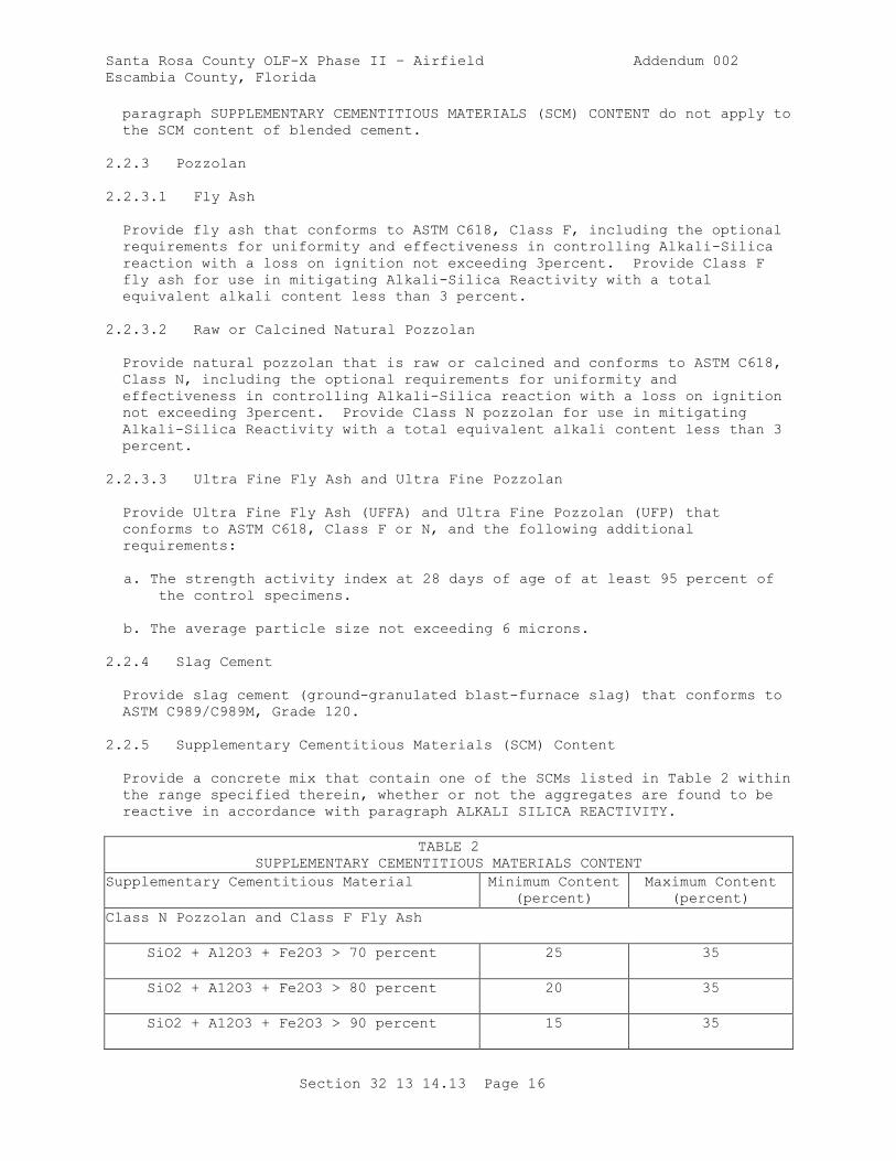
Santa Rosa County OLF-X Phase II – Airfield Addendum 002
Escambia County, Florida
Section 32 13 14.13 Page 16
paragraph SUPPLEMENTARY CEMENTITIOUS MATERIALS (SCM) CONTENT do not apply to
the SCM content of blended cement.
2.2.3 Pozzolan
2.2.3.1 Fly Ash
Provide fly ash that conforms to ASTM C618, Class F, including the optional
requirements for uniformity and effectiveness in controlling Alkali-Silica
reaction with a loss on ignition not exceeding 3percent. Provide Class F
fly ash for use in mitigating Alkali-Silica Reactivity with a total
equivalent alkali content less than 3 percent.
2.2.3.2 Raw or Calcined Natural Pozzolan
Provide natural pozzolan that is raw or calcined and conforms to ASTM C618,
Class N, including the optional requirements for uniformity and
effectiveness in controlling Alkali-Silica reaction with a loss on ignition
not exceeding 3percent. Provide Class N pozzolan for use in mitigating
Alkali-Silica Reactivity with a total equivalent alkali content less than 3
percent.
2.2.3.3 Ultra Fine Fly Ash and Ultra Fine Pozzolan
Provide Ultra Fine Fly Ash (UFFA) and Ultra Fine Pozzolan (UFP) that
conforms to ASTM C618, Class F or N, and the following additional
requirements:
a. The strength activity index at 28 days of age of at least 95 percent of
the control specimens.
b. The average particle size not exceeding 6 microns.
2.2.4 Slag Cement
Provide slag cement (ground-granulated blast-furnace slag) that conforms to
ASTM C989/C989M, Grade 120.
2.2.5 Supplementary Cementitious Materials (SCM) Content
Provide a concrete mix that contain one of the SCMs listed in Table 2 within
the range specified therein, whether or not the aggregates are found to be
reactive in accordance with paragraph ALKALI SILICA REACTIVITY.
TABLE 2
SUPPLEMENTARY CEMENTITIOUS MATERIALS CONTENT
Supplementary Cementitious Material Minimum Content
(percent)
Maximum Content
(percent)
Class N Pozzolan and Class F Fly Ash
SiO2 + Al2O3 + Fe2O3 > 70 percent 25 35
SiO2 + A12O3 + Fe2O3 > 80 percent 20 35
SiO2 + A12O3 + Fe2O3 > 90 percent 15 35
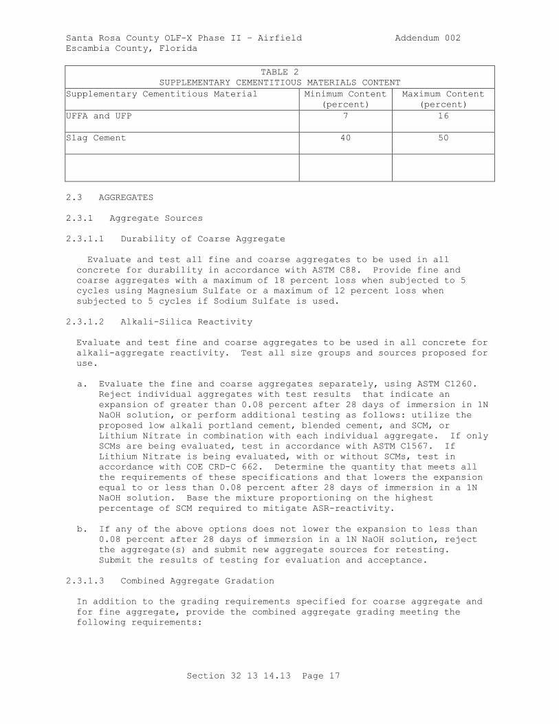
Santa Rosa County OLF-X Phase II – Airfield Addendum 002
Escambia County, Florida
Section 32 13 14.13 Page 17
TABLE 2
SUPPLEMENTARY CEMENTITIOUS MATERIALS CONTENT
Supplementary Cementitious Material Minimum Content
(percent)
Maximum Content
(percent)
UFFA and UFP 7 16
Slag Cement 40 50
2.3 AGGREGATES
2.3.1 Aggregate Sources
2.3.1.1 Durability of Coarse Aggregate
Evaluate and test all fine and coarse aggregates to be used in all
concrete for durability in accordance with ASTM C88. Provide fine and
coarse aggregates with a maximum of 18 percent loss when subjected to 5
cycles using Magnesium Sulfate or a maximum of 12 percent loss when
subjected to 5 cycles if Sodium Sulfate is used.
2.3.1.2 Alkali-Silica Reactivity
Evaluate and test fine and coarse aggregates to be used in all concrete for
alkali-aggregate reactivity. Test all size groups and sources proposed for
use.
a. Evaluate the fine and coarse aggregates separately, using ASTM C1260.
Reject individual aggregates with test results that indicate an
expansion of greater than 0.08 percent after 28 days of immersion in 1N
NaOH solution, or perform additional testing as follows: utilize the
proposed low alkali portland cement, blended cement, and SCM, or
Lithium Nitrate in combination with each individual aggregate. If only
SCMs are being evaluated, test in accordance with ASTM C1567. If
Lithium Nitrate is being evaluated, with or without SCMs, test in
accordance with COE CRD-C 662. Determine the quantity that meets all
the requirements of these specifications and that lowers the expansion
equal to or less than 0.08 percent after 28 days of immersion in a 1N
NaOH solution. Base the mixture proportioning on the highest
percentage of SCM required to mitigate ASR-reactivity.
b. If any of the above options does not lower the expansion to less than
0.08 percent after 28 days of immersion in a 1N NaOH solution, reject
the aggregate(s) and submit new aggregate sources for retesting.
Submit the results of testing for evaluation and acceptance.
2.3.1.3 Combined Aggregate Gradation
In addition to the grading requirements specified for coarse aggregate and
for fine aggregate, provide the combined aggregate grading meeting the
following requirements:

Santa Rosa County OLF-X Phase II – Airfield Addendum 002
Escambia County, Florida
Section 32 13 14.13 Page 18
a. Provide materials selected and the proportions used such that when the
Coarseness Factor (CF) and the Workability Factor (WF) are plotted on a
diagram as described in d. below, the point and its associated
production tolerance thus determined falls within the parallelogram
described therein. Refer to AF ETL 97-5 for combined aggregate plot
area recommendations for the intended placement technique(s).
b. Determine the Coarseness Factor (CF) from the following equation:
CF = (cumulative percent retained on the 3/8 inch sieve)(100)
(cumulative percent retained on the No. 8 sieve)
c. The Workability Factor (WF) is defined as the percent passing the No. 8
sieve based on the combined gradation. Adjust the WF, prorated upwards
only, by 2.5 percentage points for each 94 pounds of cementitious
material per cubic yard greater than 564 pounds per cubic yard.
d. Plot a diagram using a rectangular scale with WF on the Y-axis with
units from 20 (bottom) to 45 (top), and with CF on the X-axis with
units from 80 (left side) to 30 (right side). On this diagram, plot a
parallelogram with corners at the following coordinates (CF-75, WF-28),
(CF-75, WF-40), (CF-45, WF-32.5), and (CF-45, WF-44.5). If the point
determined by the intersection of the computed CF and WF does not fall
within the above parallelogram, revise the grading of each size of
aggregate used and the proportions selected as necessary.
e. Plot the associated production tolerance limits, identified in Table 6,
around the CF and adjusted WF point.
2.3.2 Coarse Aggregate
2.3.2.1 Material Composition
Provide coarse aggregate consisting of crushed or uncrushed gravel, crushed
stone, , or a combination thereof. Provide aggregate used for paving
compass calibration hardstands free of materials having undesirable magnetic
properties, including magnetite in granite, high-iron minerals in traprock,
and pyrite in limestone. Provide aggregates, as delivered to the mixers,
consisting of clean, hard, uncoated particles meeting the requirements of
ASTM C33/C33M except as specified herein. . Provide coarse aggregate with
no more than 40 percent loss when subjected to the Los Angeles abrasion test
in accordance with ASTM C131/C131M. Provide coarse aggregates with a
maximum sodium sulfate soundness loss of 12 percent, or with a magnesium
sulfate soundness loss of 18 percent after five cycles when tested in
accordance with ASTM C88.
2.3.2.2 Particle Shape Characteristics
Provide particles of the coarse aggregate that are generally spherical or
cubical in shape. The quantity of flat particles and elongated particles in
any size group coarser than the 3/8 inch sieve are not allowed to exceed 20
percent by weight as determined by the Flat Particle Test and the Elongated
Particle Test of ASTM D4791. A flat particle is defined as one having a
ratio of width to thickness greater than 3; an elongated particle is one
having a ratio of length to width greater than 3.
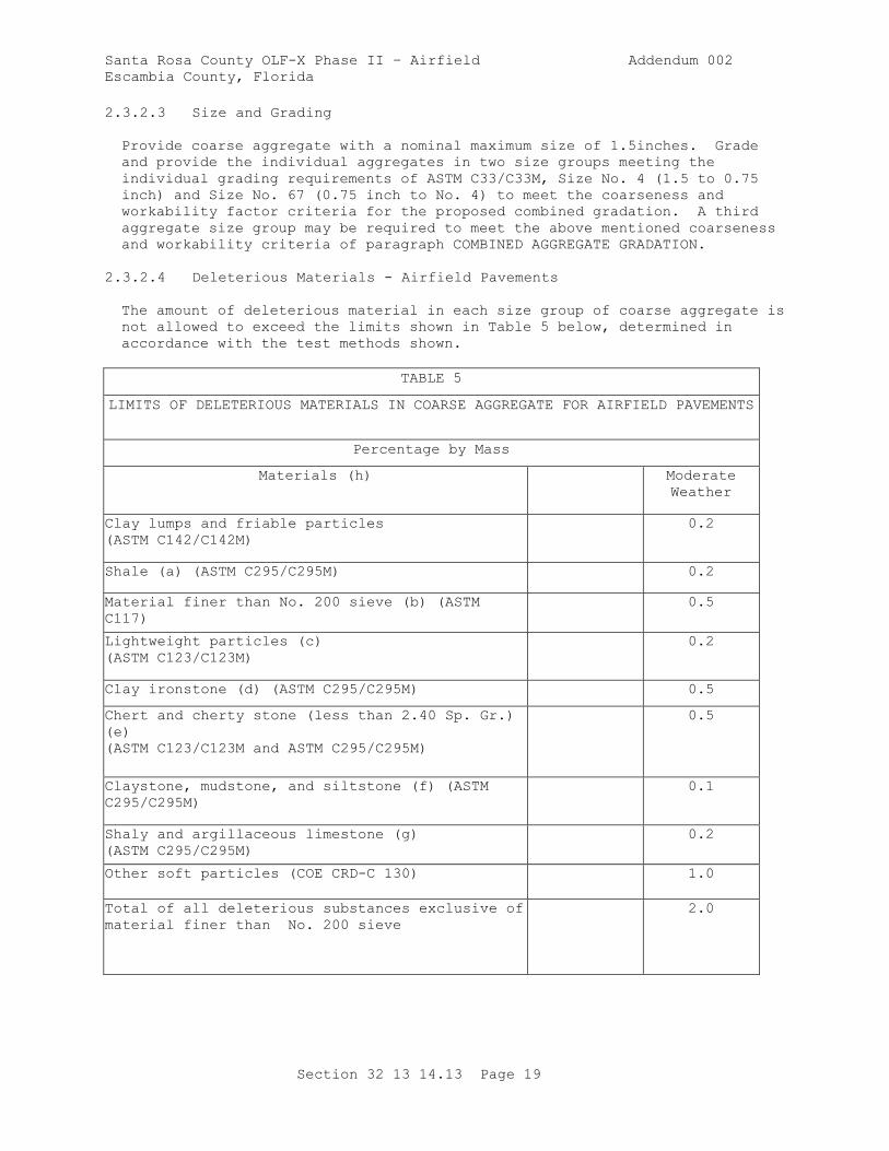
Santa Rosa County OLF-X Phase II – Airfield Addendum 002
Escambia County, Florida
Section 32 13 14.13 Page 19
2.3.2.3 Size and Grading
Provide coarse aggregate with a nominal maximum size of 1.5inches. Grade
and provide the individual aggregates in two size groups meeting the
individual grading requirements of ASTM C33/C33M, Size No. 4 (1.5 to 0.75
inch) and Size No. 67 (0.75 inch to No. 4) to meet the coarseness and
workability factor criteria for the proposed combined gradation. A third
aggregate size group may be required to meet the above mentioned coarseness
and workability criteria of paragraph COMBINED AGGREGATE GRADATION.
2.3.2.4 Deleterious Materials - Airfield Pavements
The amount of deleterious material in each size group of coarse aggregate is
not allowed to exceed the limits shown in Table 5 below, determined in
accordance with the test methods shown.
TABLE 5
LIMITS OF DELETERIOUS MATERIALS IN COARSE AGGREGATE FOR AIRFIELD PAVEMENTS
Percentage by Mass
Materials (h) Moderate
Weather
Clay lumps and friable particles
(ASTM C142/C142M)
0.2
Shale (a) (ASTM C295/C295M) 0.2
Material finer than No. 200 sieve (b) (ASTM
C117)
0.5
Lightweight particles (c)
(ASTM C123/C123M)
0.2
Clay ironstone (d) (ASTM C295/C295M) 0.5
Chert and cherty stone (less than 2.40 Sp. Gr.)
(e)
(ASTM C123/C123M and ASTM C295/C295M)
0.5
Claystone, mudstone, and siltstone (f) (ASTM
C295/C295M)
0.1
Shaly and argillaceous limestone (g)
(ASTM C295/C295M)
0.2
Other soft particles (COE CRD-C 130) 1.0
Total of all deleterious substances exclusive of
material finer than No. 200 sieve
2.0
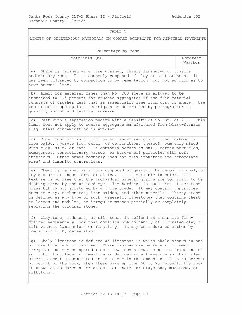
Santa Rosa County OLF-X Phase II – Airfield Addendum 002
Escambia County, Florida
Section 32 13 14.13 Page 20
TABLE 5
LIMITS OF DELETERIOUS MATERIALS IN COARSE AGGREGATE FOR AIRFIELD PAVEMENTS
Percentage by Mass
Materials (h) Moderate
Weather
(a) Shale is defined as a fine-grained, thinly laminated or fissile
sedimentary rock. It is commonly composed of clay or silt or both. It
has been indurated by compaction or by cementation, but not so much as to
have become slate.
(b) Limit for material finer than No. 200 sieve is allowed to be
increased to 1.5 percent for crushed aggregates if the fine material
consists of crusher dust that is essentially free from clay or shale. Use
XRD or other appropriate techniques as determined by petrographer to
quantify amount and justify increase.
(c) Test with a separation medium with a density of Sp. Gr. of 2.0. This
limit does not apply to coarse aggregate manufactured from blast-furnace
slag unless contamination is evident.
(d) Clay ironstone is defined as an impure variety of iron carbonate,
iron oxide, hydrous iron oxide, or combinations thereof, commonly mixed
with clay, silt, or sand. It commonly occurs as dull, earthy particles,
homogeneous concretionary masses, or hard-shell particles with soft
interiors. Other names commonly used for clay ironstone are "chocolate
bars" and limonite concretions.
(e) Chert is defined as a rock composed of quartz, chalcedony or opal, or
any mixture of these forms of silica. It is variable in color. The
texture is so fine that the individual mineral grains are too small to be
distinguished by the unaided eye. Its hardness is such that it scratches
glass but is not scratched by a knife blade. It may contain impurities
such as clay, carbonates, iron oxides, and other minerals. Cherty stone
is defined as any type of rock (generally limestone) that contains chert
as lenses and nodules, or irregular masses partially or completely
replacing the original stone.
(f) Claystone, mudstone, or siltstone, is defined as a massive fine-
grained sedimentary rock that consists predominantly of indurated clay or
silt without laminations or fissility. It may be indurated either by
compaction or by cementation.
(g) Shaly limestone is defined as limestone in which shale occurs as one
or more thin beds or laminae. These laminae may be regular or very
irregular and may be spaced from a few inches down to minute fractions of
an inch. Argillaceous limestone is defined as a limestone in which clay
minerals occur disseminated in the stone in the amount of 10 to 50 percent
by weight of the rock; when these make up from 50 to 90 percent, the rock
is known as calcareous (or dolomitic) shale (or claystone, mudstone, or
siltstone).
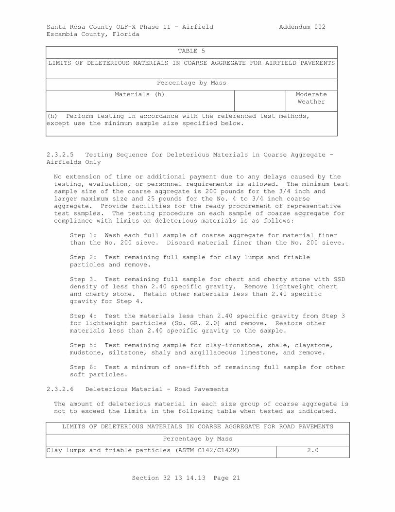
Santa Rosa County OLF-X Phase II – Airfield Addendum 002
Escambia County, Florida
Section 32 13 14.13 Page 21
TABLE 5
LIMITS OF DELETERIOUS MATERIALS IN COARSE AGGREGATE FOR AIRFIELD PAVEMENTS
Percentage by Mass
Materials (h) Moderate
Weather
(h) Perform testing in accordance with the referenced test methods,
except use the minimum sample size specified below.
2.3.2.5 Testing Sequence for Deleterious Materials in Coarse Aggregate -
Airfields Only
No extension of time or additional payment due to any delays caused by the
testing, evaluation, or personnel requirements is allowed. The minimum test
sample size of the coarse aggregate is 200 pounds for the 3/4 inch and
larger maximum size and 25 pounds for the No. 4 to 3/4 inch coarse
aggregate. Provide facilities for the ready procurement of representative
test samples. The testing procedure on each sample of coarse aggregate for
compliance with limits on deleterious materials is as follows:
Step 1: Wash each full sample of coarse aggregate for material finer
than the No. 200 sieve. Discard material finer than the No. 200 sieve.
Step 2: Test remaining full sample for clay lumps and friable
particles and remove.
Step 3. Test remaining full sample for chert and cherty stone with SSD
density of less than 2.40 specific gravity. Remove lightweight chert
and cherty stone. Retain other materials less than 2.40 specific
gravity for Step 4.
Step 4: Test the materials less than 2.40 specific gravity from Step 3
for lightweight particles (Sp. GR. 2.0) and remove. Restore other
materials less than 2.40 specific gravity to the sample.
Step 5: Test remaining sample for clay-ironstone, shale, claystone,
mudstone, siltstone, shaly and argillaceous limestone, and remove.
Step 6: Test a minimum of one-fifth of remaining full sample for other
soft particles.
2.3.2.6 Deleterious Material - Road Pavements
The amount of deleterious material in each size group of coarse aggregate is
not to exceed the limits in the following table when tested as indicated.
LIMITS OF DELETERIOUS MATERIALS IN COARSE AGGREGATE FOR ROAD PAVEMENTS
Percentage by Mass
Clay lumps and friable particles (ASTM C142/C142M) 2.0
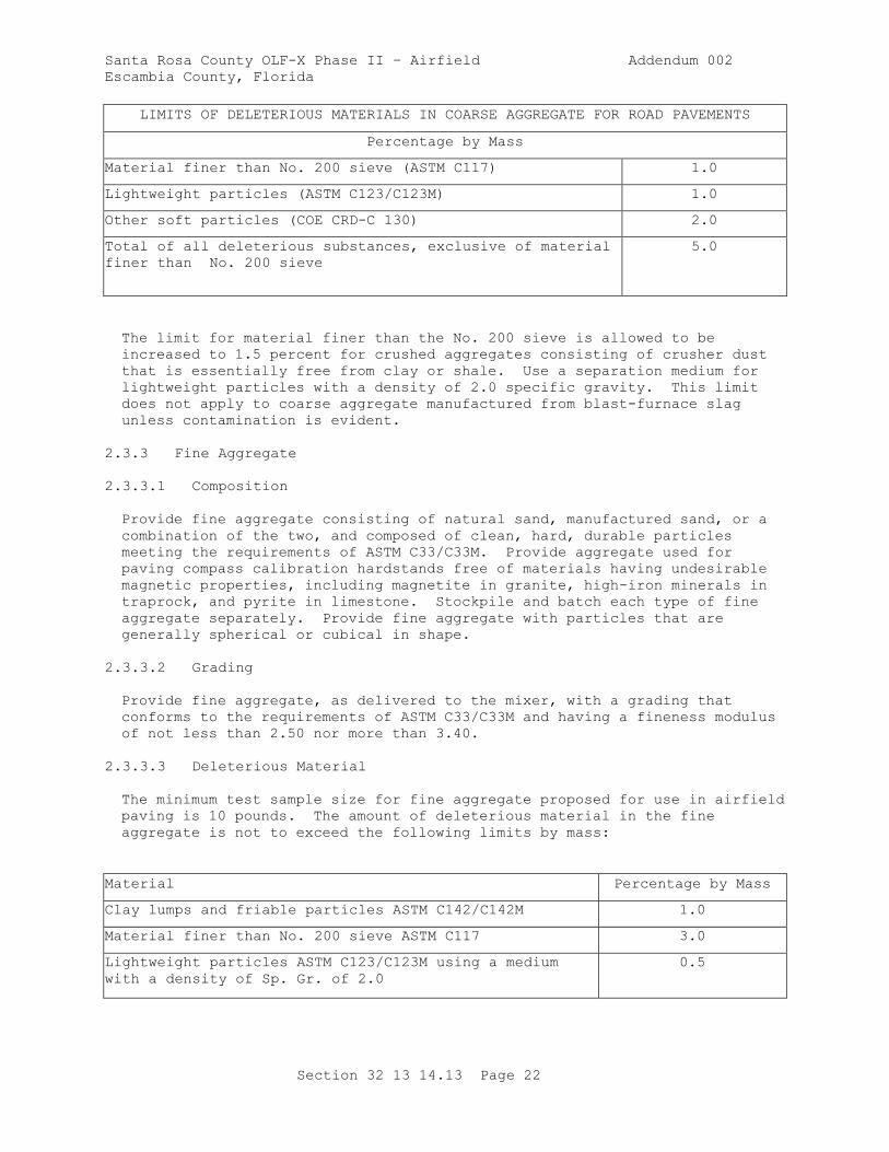
Santa Rosa County OLF-X Phase II – Airfield Addendum 002
Escambia County, Florida
Section 32 13 14.13 Page 22
LIMITS OF DELETERIOUS MATERIALS IN COARSE AGGREGATE FOR ROAD PAVEMENTS
Percentage by Mass
Material finer than No. 200 sieve (ASTM C117) 1.0
Lightweight particles (ASTM C123/C123M) 1.0
Other soft particles (COE CRD-C 130) 2.0
Total of all deleterious substances, exclusive of material
finer than No. 200 sieve
5.0
The limit for material finer than the No. 200 sieve is allowed to be
increased to 1.5 percent for crushed aggregates consisting of crusher dust
that is essentially free from clay or shale. Use a separation medium for
lightweight particles with a density of 2.0 specific gravity. This limit
does not apply to coarse aggregate manufactured from blast-furnace slag
unless contamination is evident.
2.3.3 Fine Aggregate
2.3.3.1 Composition
Provide fine aggregate consisting of natural sand, manufactured sand, or a
combination of the two, and composed of clean, hard, durable particles
meeting the requirements of ASTM C33/C33M. Provide aggregate used for
paving compass calibration hardstands free of materials having undesirable
magnetic properties, including magnetite in granite, high-iron minerals in
traprock, and pyrite in limestone. Stockpile and batch each type of fine
aggregate separately. Provide fine aggregate with particles that are
generally spherical or cubical in shape.
2.3.3.2 Grading
Provide fine aggregate, as delivered to the mixer, with a grading that
conforms to the requirements of ASTM C33/C33M and having a fineness modulus
of not less than 2.50 nor more than 3.40.
2.3.3.3 Deleterious Material
The minimum test sample size for fine aggregate proposed for use in airfield
paving is 10 pounds. The amount of deleterious material in the fine
aggregate is not to exceed the following limits by mass:
Material Percentage by Mass
Clay lumps and friable particles ASTM C142/C142M 1.0
Material finer than No. 200 sieve ASTM C117 3.0
Lightweight particles ASTM C123/C123M using a medium
with a density of Sp. Gr. of 2.0
0.5
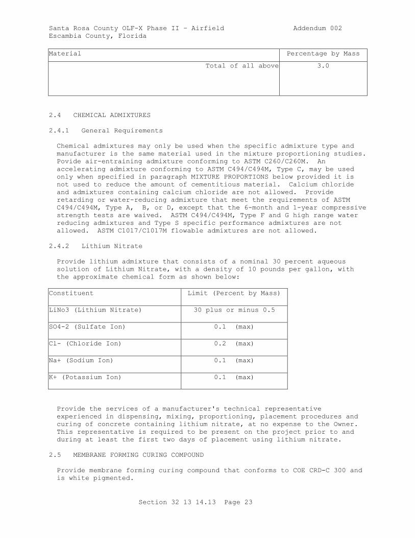
Santa Rosa County OLF-X Phase II – Airfield Addendum 002
Escambia County, Florida
Section 32 13 14.13 Page 23
Material Percentage by Mass
Total of all above 3.0
2.4 CHEMICAL ADMIXTURES
2.4.1 General Requirements
Chemical admixtures may only be used when the specific admixture type and
manufacturer is the same material used in the mixture proportioning studies.
Povide air-entraining admixture conforming to ASTM C260/C260M. An
accelerating admixture conforming to ASTM C494/C494M, Type C, may be used
only when specified in paragraph MIXTURE PROPORTIONS below provided it is
not used to reduce the amount of cementitious material. Calcium chloride
and admixtures containing calcium chloride are not allowed. Provide
retarding or water-reducing admixture that meet the requirements of ASTM
C494/C494M, Type A, B, or D, except that the 6-month and 1-year compressive
strength tests are waived. ASTM C494/C494M, Type F and G high range water
reducing admixtures and Type S specific performance admixtures are not
allowed. ASTM C1017/C1017M flowable admixtures are not allowed.
2.4.2 Lithium Nitrate
Provide lithium admixture that consists of a nominal 30 percent aqueous
solution of Lithium Nitrate, with a density of 10 pounds per gallon, with
the approximate chemical form as shown below:
Constituent Limit (Percent by Mass)
LiNo3 (Lithium Nitrate) 30 plus or minus 0.5
SO4-2 (Sulfate Ion) 0.1 (max)
Cl- (Chloride Ion) 0.2 (max)
Na+ (Sodium Ion) 0.1 (max)
K+ (Potassium Ion) 0.1 (max)
Provide the services of a manufacturer's technical representative
experienced in dispensing, mixing, proportioning, placement procedures and
curing of concrete containing lithium nitrate, at no expense to the Owner.
This representative is required to be present on the project prior to and
during at least the first two days of placement using lithium nitrate.
2.5 MEMBRANE FORMING CURING COMPOUND
Provide membrane forming curing compound that conforms to COE CRD-C 300 and
is white pigmented.
Santa Rosa County OLF-X Phase II – Airfield Addendum 002
Escambia County, Florida
Section 32 13 14.13 Page 24
2.6 WATER
Provide water for mixing and curing that is fresh, clean, potable, and free
of injurious amounts of oil, acid, salt, or alkali, except that non-potable
water, or water from concrete production operations, may be used if it meets
the requirements of ASTM C1602/C1602M.
2.7 JOINT MATERIALS
2.7.1 Expansion Joint Material
Provide preformed expansion joint filler material conforming to ASTM D1751
or ASTM D1752 Type II. Provide expansion joint filler that is 3/4 inch
thick, unless otherwise indicated, and provided in a single full depth
piece.
2.7.2 Slip Joint Material
Provide slip joint material that is 1/4 inch thick expansion joint filler,
unless otherwise indicated, conforming to paragraph EXPANSION JOINT
MATERIAL.
2.8 REINFORCING
Provide reinforcement that is free from loose, flaky rust, loose scale, oil,
grease, mud, or other coatings that might reduce the bond with concrete.
Removal of thin powdery rust and tight rust is not required. However,
reinforcing steel which is rusted to the extent that it does not conform to
the required dimensions or mechanical properties is not allowed to be used.
2.8.1 Reinforcing Bars and Bar Mats
Provide reinforcing bars conforming to ASTM A615/A615M, billet-steel ASTM
A996/A996M, rail and axle steel, Grade 60 . Provide bar mats conforming to
ASTM A184/A184M. The bar members may be billet rail or axle steel.
2.8.2 Welded Wire Reinforcement
Provide welded wire reinforcement that is deformed or smooth, conforming to
ASTM A1064/A1064M or ASTM A185/A185M, and is provided in flat sheets.
2.9 DOWELS AND TIE BARS
2.9.1 Dowels
Provide dowels in single piece bars fabricated or cut to length at the shop
or mill before delivery to the site. Dowels are to be free of loose, flaky
rust and loose scale and be clean and straight. Dowels may be sheared to
length provided that the deformation from true shape caused by shearing does
not exceed 0.04 inch on the diameter of the dowel and does not extend more
than 0.04 inch from the end of the dowel. Dowels are required to be plain
(non-deformed) steel bars conforming to ASTM A615/A615M, Grade 40 or 60;
ASTM A996/A996M, Grade 50 or 60. Dowel bars are required to be epoxy coated
in conformance with ASTM A775/A775M, to include the ends. Provide grout
retention rings that are fully circular metal or plastic devices capable of
Santa Rosa County OLF-X Phase II – Airfield Addendum 002
Escambia County, Florida
Section 32 13 14.13 Page 25
supporting the dowel until the epoxy hardens. Dowel sleeves or inserts are
not permitted.
2.9.2 Dowel Bar Assemblies
Provide dowel bar assemblies that consist of a framework of metal bars or
wires arranged to provide rigid support for the dowels throughout the paving
operation, with a minimum of four continuous bars or wires extending along
the joint line. Provide dowels that are welded to the assembly or held
firmly by mechanical locking arrangements that prevent them from rising,
sliding out, or becoming distorted during paving operations.
2.9.3 Tie Bars
Provide tie bars that are deformed steel bars conforming to ASTM A615/A615M,
or ASTM A996/A996M, Grade 60 , and of the sizes and dimensions indicated.
Deformed rail steel bars and high-strength billet or axle steel bars, Grade
50 or higher, are not allowed to be used for bars that are bent and
straightened during construction.
2.10 EPOXY RESIN
Provide epoxy-resin materials that consist of two-component materials
conforming to the requirements of ASTM C881/C881M, Class as appropriate for
each application temperature to be encountered, except that in addition, the
materials meet the following requirements:
a. Material for use for embedding dowels and anchor bolts be Type IV,
Grade 3.
b. Material for use as patching materials for complete filling of spalls
and other voids and for use in preparing epoxy resin mortar be Type
III, Grade as approved.
c. Material for use for injecting cracks be Type IV, Grade 1.
d. Material for bonding freshly mixed portland cement concrete or mortar
or freshly mixed epoxy resin concrete or mortar to hardened concrete be
Type V, Grade as approved.
2.11 EQUIPMENT
All plant, equipment, tools, and machines used in the work are required to
be maintained in satisfactory working conditions at all times. Submit the
following:
a. Details and data on the batching and mixing plant prior to plant
assembly including manufacturer's literature showing that the equipment
meets all requirements specified herein.
b. Obtain National Ready Mixed Concrete Association (NRMCA) certification
of the concrete plant, at no expense to the Owner. Provide inspection
report of the concrete plant by an engineer approved by the NRMCA. A
list of NRMCA approved engineers is available on the NRMCA website at
http://www.nrmca.org. Submit a copy of the NRMCA QC Manual Section 3
Concrete Plant Certification Checklist, NRMCA Certificate of
Santa Rosa County OLF-X Phase II – Airfield Addendum 002
Escambia County, Florida
Section 32 13 14.13 Page 26
Conformance, and Calibration documentation on all measuring and
weighing devices prior to uniformity testing.
c. A description of the equipment proposed for transporting concrete
mixture from the central mixing plant to the paving equipment.
d. A description of the equipment proposed for the machine and hand
placing, consolidating and curing of the concrete mixture.
Manufacturer's literature on the paver and finisher, together with the
manufacturer's written instructions on adjustments and operating
procedures necessary to assure a tight, smooth surface on the concrete
pavement. The literature is required to show that the equipment meets
all details of these specifications.
2.11.1 Batching and Mixing Plant
2.11.1.1 Location
Locate the batching and mixing plant off Owner premises no more than 15
minutes haul time from the placing site. Water and electrical power are
available on the project site. Provide operable telephonic or radio
communication between the plant and the placing site at all times concreting
is taking place.
2.11.1.2 Type and Capacity
Provide a batching and mixing plant consisting of a stationary-type central
mix plant, including permanent installations and portable or relocatable
plants installed on stable foundations. Provide a plant designed and
operated to produce concrete within the specified tolerances, with a minimum
capacity of 250 cubic yards per hour, that conforms to the requirements of
NRMCA QC 3 including provisions addressing:
1. Material Storage and Handling
2. Batching Equipment
3. Central Mixer
4. Ticketing System
5. Delivery System
2.11.1.3 Tolerances
Materials Percentage of Required Mass
Cementitious Materials plus or minus 1
Aggregate plus or minus 2
Water plus or minus 1
Admixture plus or minus 3
For volumetric batching equipment for water and admixtures, the above
numeric tolerances apply to the required volume of material being batched.
Dilute concentrated admixtures uniformly, if necessary, to provide
Santa Rosa County OLF-X Phase II – Airfield Addendum 002
Escambia County, Florida
Section 32 13 14.13 Page 27
sufficient volume per batch to ensure that the batchers consistently operate
within the above tolerance.
2.11.1.4 Moisture Control
Provide a plant capable of ready adjustment to compensate for the varying
moisture contents of the aggregates and to change the quantities of the
materials being batched.
2.11.2 Concrete Mixers
Provide stationary or truck mixers that are capable of combining the
materials into a uniform mixture and of discharging this mixture without
segregation. Do not charge the mixers in excess of the capacity recommended
by the manufacturer. Operate the mixers at the drum or mixing blade speed
designated by the manufacturer. Maintain the mixers in satisfactory
operating condition, with the mixer drums kept free of hardened concrete.
Replace mixer blades or paddles when worn down more than 10 percent of their
depth when compared with the manufacturer's dimension for new blades or
paddles.
2.11.2.1 Stationary
Stationary mixers are required to be drum or pan mixers. Provide mixers
with an acceptable device to lock the discharge mechanism until the required
mixing time has elapsed.
2.11.2.2 Mixing Time and Uniformity for Stationary Mixers
For stationary mixers, before uniformity data are available, the minimum
mixing time for each batch after all solid materials are in the mixer,
provided that all of the mixing water is introduced before one-fourth of the
mixing time has elapsed, is 1 minute for mixers having a capacity of 1 cubic
yard. For mixers of greater capacity, increase this minimum time by 20
seconds for each additional 1.33 cubic yard or fraction thereof. After
results of uniformity tests are available, the mixing time may be reduced to
the minimum time required to meet uniformity requirements; but if uniformity
requirements are not being met, increase the mixing time as directed.
Perform mixer performance tests at new mixing times immediately after any
change in mixing time or volume. Conduct the Regular Test sequence for
initial determination of the mixing time or as directed. When regular
testing is performed, the concrete is required to meet the limits of any
five of the six uniformity requirements listed in Table 1 below.
2.11.2.3 Abbreviated Test
Conduct the Abbreviated Test sequence for production concrete verification
at the frequency specified in Table 6. When abbreviated testing is
performed, the concrete is required to meet only those requirements listed
for abbreviated testing. Use the projects approved mix design proportions
for uniformity testing. For regular testing perform all six tests on three
batches of concrete. The range for regular testing is the average of the
ranges of the three batches. Abbreviated testing consists of performing the
three required tests on a single batch of concrete. The range for
abbreviated testing is the range for one batch. If more than one mixer is
used and all are identical in terms of make, type, capacity, condition,
speed of rotation, the results of tests on one of the mixers apply to the
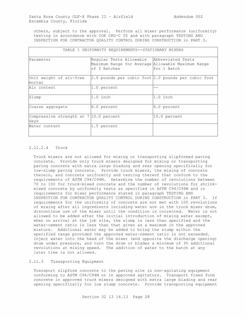
Santa Rosa County OLF-X Phase II – Airfield Addendum 002
Escambia County, Florida
Section 32 13 14.13 Page 28
others, subject to the approval. Perform all mixer performance (uniformity)
testing in accordance with COE CRD-C 55 and with paragraph TESTING AND
INSPECTION FOR CONTRACTOR QUALITY CONTROL DURING CONSTRUCTION in PART 3.
TABLE 1 UNIFORMITY REQUIREMENTS--STATIONARY MIXERS
Parameter Regular Tests Allowable
Maximum Range for Average
of 3 Batches
Abbreviated Tests
Allowable Maximum Range
for 1 Batch
Unit weight of air-free
mortar
2.0 pounds per cubic foot 2.0 pounds per cubic foot
Air content 1.0 percent --
Slump 1.0 inch 1.0 inch
Coarse aggregate 6.0 percent 6.0 percent
Compressive strength at 7
days
10.0 percent 10.0 percent
Water content 1.5 percent
2.11.2.4 Truck
Truck mixers are not allowed for mixing or transporting slipformed paving
concrete. Provide only truck mixers designed for mixing or transporting
paving concrete with extra large blading and rear opening specifically for
low-slump paving concrete. Provide truck mixers, the mixing of concrete
therein, and concrete uniformity and testing thereof that conform to the
requirements of ASTM C94/C94M. Determine the number of revolutions between
70 to 100 for truck-mixed concrete and the number of revolutions for shrink-
mixed concrete by uniformity tests as specified in ASTM C94/C94M and in
requirements for mixer performance stated in paragraph TESTING AND
INSPECTION FOR CONTRACTOR QUALITY CONTROL DURING CONSTRUCTION in PART 3. If
requirements for the uniformity of concrete are not met with 100 revolutions
of mixing after all ingredients including water are in the truck mixer drum,
discontinue use of the mixer until the condition is corrected. Water is not
allowed to be added after the initial introduction of mixing water except,
when on arrival at the job site, the slump is less than specified and the
water-cement ratio is less than that given as a maximum in the approved
mixture. Additional water may be added to bring the slump within the
specified range provided the approved water-cement ratio is not exceeded.
Inject water into the head of the mixer (end opposite the discharge opening)
drum under pressure, and turn the drum or blades a minimum of 30 additional
revolutions at mixing speed. The addition of water to the batch at any
later time is not allowed.
2.11.3 Transporting Equipment
Transport slipform concrete to the paving site in non-agitating equipment
conforming to ASTM C94/C94M or in approved agitators. Transport fixed form
concrete in approved truck mixers designed with extra large blading and rear
opening specifically for low slump concrete. Provide transporting equipment
Santa Rosa County OLF-X Phase II – Airfield Addendum 002
Escambia County, Florida
Section 32 13 14.13 Page 29
designed and operated to deliver and discharge the required concrete mixture
completely without segregation.
2.11.4 Paver-Finisher
Provide paver-finisher consisting of a heavy-duty, self-propelled machine
designed specifically for paving and finishing high quality pavement, with a
minimum weight of 2200 pounds per foot of lane width, and powered by an
engine having a minimum 6.0 horsepower per foot of lane width. The paver-
finisher is required to spread, consolidate, and shape the plastic concrete
to the desired cross section in one pass. The mechanisms for forming the
pavement are required to be easily adjustable in width and thickness and for
required crown. In addition to other spreaders required by paragraph above,
the paver-finisher equipped with a full width knock-down auger or paddle
mechanism, capable of operating in both directions, which evenly spreads the
fresh concrete in front of the screed or extrusion plate.
2.11.4.1 Vibrators
Provide gang mounted immersion vibrators at the front of the paver on a
frame equipped with suitable controls so that all vibrators can be operated
at any desired depth within the slab or completely withdrawn from the
concrete, as required. Provide vibrators that are automatically controlled
to immediately stop as forward motion of the paver ceases. Equipped the
paver-finisher with an electronic vibrator monitoring device displaying the
operating frequency of each individual internal vibrator with a readout
display visible to the paver operator that operates continuously while
paving, and displays all vibrator frequencies with manual or automatic
sequencing among all individual vibrators. Discontinue paving if the
vibrator monitoring system fails to operate properly during the paving
operation. Provide the spacing of the immersion vibrators across the paving
lane as necessary to properly consolidate the concrete, with a maximum clear
distance between vibrators of 30 inches and outside vibrators a maximum of
12 inches from the lane edge. Operate spud vibrators at a minimum frequency
of 8000 impulses per minute and a minimum amplitude of 0.03 inch, as
determined by COE CRD-C 521.
2.11.4.2 Screed or Extrusion Plate
Equipped the paver-finisher with a transversely oscillating screed or an
extrusion plate to shape, compact, and smooth the surface and finish the
surface that no significant amount of hand finishing, except use of cutting
straightedges, is required. Provide a screed or extrusion plate constructed
to adjust for crown in the pavement. Provide adjustment for variation in
lane width or thickness and to prevent more than 8 inches of the screed or
extrusion plate extending over previously placed concrete on either end when
paving fill-in lanes. Repair or replace machines that cause displacement of
properly installed forms or cause ruts or indentations in the prepared
underlying materials and machines that cause frequent delays due to
mechanical failures as directed.
2.11.4.3 Longitudinal Mechanical Float
A longitudinal mechanical float may be used. If used, provide a float that
is specially designed and manufactured to smooth and finish the pavement
surface without working excess paste to the surface that is rigidly attached
to the rear of the paver-finisher or to a separate self-propelled frame
Santa Rosa County OLF-X Phase II – Airfield Addendum 002
Escambia County, Florida
Section 32 13 14.13 Page 30
spanning the paving lane. Provide float plate at least 5 feet long by 8
inches wide and automatically be oscillated in the longitudinal direction
while slowly moving from edge to edge of the paving lane, with the float
plate in contact with the surface at all times.
2.11.4.4 Other Types of Finishing Equipment
Clary screeds, other rotating tube floats, or bridge deck finishers are not
allowed on mainline paving, but may be allowed on irregular or odd-shaped
slabs, and near buildings or trench drains, subject to approval. Provide
bridge deck finishers with a minimum operating weight of 7500 pounds that
have a transversely operating carriage containing a knock-down auger and a
minimum of two immersion vibrators. Only use vibrating screeds or pans for
isolated slabs where hand finishing is permitted as specified, and only
where specifically approved.
2.11.4.5 Fixed Forms
Provide paver-finisher equipped with wheels designed to ride the forms, keep
it aligned with the forms, and spread the load so as to prevent deformation
of the forms. Provide paver-finishers traveling on guide rails located
outside the paving lane that are equipped with wheels when traveling on new
or existing concrete to remain. Alternatively, a modified slipform paver
that straddles the forms may be used. Provide a modified slipform paver
which has the side conforming plates removed or rendered ineffective and
travels over or along pre-placed fixed forms.
2.11.4.6 Slipform
The slipform paver-finisher is required to be automatically controlled and
crawler mounted with padded tracks so as to be completely stable under all
operating conditions and provide a finish to the surface and edges so that
no edge slump beyond allowable tolerance occurs. Provide suitable moving
side forms that are adjustable and produce smooth, even edges, perpendicular
to the top surface and meeting specification requirements for alignment and
freedom from edge slump.
2.11.5 Curing Equipment
Provide equipment for applying membrane-forming curing compound mounted on a
self-propelled frame that spans the paving lane. Constantly agitate the
curing compound reservoir mechanically (not air) during operation and
provide a means for completely draining the reservoir. Provide a spraying
system that consists of a mechanically powered pump which maintains constant
pressure during operation, an operable pressure gauge, and either a series
of spray nozzles evenly spaced across the lane to provide uniformly
overlapping coverage or a single spray nozzle which is mounted on a carriage
which automatically traverses the lane width at a speed correlated with the
forward movement of the overall frame. Protect all spray nozzles with wind
screens. Calibrate the spraying system in accordance with ASTM D2995,
Method A, for the rate of application required in paragraph MEMBRANE CURING.
Provide hand-operated sprayers allowed by that paragraph with compressed air
supplied by a mechanical air compressor. Immediately replace curing
equipment if it fails to apply an even coating of compound at the specified
rate.
Santa Rosa County OLF-X Phase II – Airfield Addendum 002
Escambia County, Florida
Section 32 13 14.13 Page 31
2.11.6 Texturing Equipment
Provide texturing equipment as specified below. Before use, demonstrate the
texturing equipment on a test section, and modify the equipment as necessary
to produce the texture directed.
2.11.6.1 Burlap Drag
Securely attach a burlap drag to a separate wheel mounted frame spanning the
paving lane or to one of the other similar pieces of equipment. Provide
length of the material between 24 to 36 inches dragging flat on the pavement
surface. Provide burlap drag with a width at least equal to the width of
the slab. Provide clean, reasonably new burlap material, completely
saturated with water before attachment to the frame, always resaturated
before start of use, and kept clean and saturated during use. Provide
burlap conforming to AASHTO M 182, Class 3 or 4.
2.11.7 Sawing Equipment
Provide equipment for sawing joints and for other similar sawing of concrete
consisting of standard diamond-type concrete saws mounted on a wheeled
chassis which can be easily guided to follow the required alignment.
Provide diamond tipped blades. If demonstrated to operate properly,
abrasive blades may be used. Provide spares as required to maintain the
required sawing rate. Provide saws capable of sawing to the full depth
required. Early-entry saws may be used, subject to demonstration and
approval. No change to the initial sawcut depth is permitted.
2.11.8 Straightedge
Provide and maintain at the job site, in good condition, a minimum 12 foot
straightedge for each paving train for testing the hardened portland cement
concrete surfaces. Provide straightedges constructed of aluminum or
magnesium alloy and blades of box or box-girder cross section with flat
bottom, adequately reinforced to insure rigidity and accuracy. Provide
straightedges with handles for operation on the pavement.
2.11.9 Work Bridge
Provide a self-propelled working bridge capable of spanning the required
paving lane width where workmen can efficiently and adequately reach the
pavement surface.
2.12 SPECIFIED CONCRETE STRENGTH AND OTHER PROPERTIES
2.12.1 Specified Flexural Strength
Specified flexural strength, R, for concrete is 650 psi at 28 days, as
determined by
2.12.2 Water-Cementitious Materials Ratio
Maximum allowable water-cementitious material ratio is 0.45. The water-
cementitious material ratio is the equivalent water-cement ratio as
determined by conversion from the weight ratio of water to cement plus SCM
by the mass equivalency method described in ACI 211.1.
Santa Rosa County OLF-X Phase II – Airfield Addendum 002
Escambia County, Florida
Section 32 13 14.13 Page 32
2.12.3 Air Content
Provide concrete that is air-entrained with a total air content of 4.0 plus
or minus 1.5 percentage points, at the point of placement. Determine air
content in accordance with ASTM C231/C231M.
2.12.4 Slump
The maximum allowable slump of the concrete at the point of placement is 2
inches for pavement constructed with fixed forms. For slipformed pavement,
at the start of the project, select a slump which produces in-place pavement
meeting the specified tolerances for control of edge slump. The selected
slump is applicable to both pilot and fill-in lanes.
2.12.5 Concrete Temperature
The temperature of the concrete as delivered is required to conform to the
requirements of paragraphs PAVING IN HOT WEATHER and PAVING IN COLD WEATHER,
in PART 3. Determine the temperature of concrete in accordance with ASTM
C1064/C1064M.
2.12.6 Concrete Strength for Final Acceptance
and no individual set (2 specimens per sublot) in the lot are 25 psi or
more below the equivalent 'Specified Flexural Strength'. If any lot or
sublot, respectively, fails to meet the above criteria, remove and replace
the lot or sublot at no additional cost to the Owner. This is in addition
to and does not replace the average strength required for day-to-day CQC
operations as specified in paragraph AVERAGE CQC FLEXURAL STRENGTH REQUIRED
FOR MIXTURES, below.
2.13 MIXTURE PROPORTIONS
2.13.1 Composition
Provide concrete composed of cementitious material, water, fine and coarse
aggregates, and admixtures. Include supplementary Cementitious Materials
(SCM) choice and usage in accordance with paragraph SUPPLEMENTARY
CEMENTITIOUS MATERIALS (SCM) CONTENT. Provide a minimum total cementitious
materials content of 470 pounds per cubic yard. Acceptable admixtures
consist of air entraining admixture and may also include, as approved, water
reducing and accelerating admixtures.
2.13.2 Proportioning Studies
Perform trial design batches, mixture proportioning studies, and testing, at
no expense to the Owner. Submit for approval the Preliminary Proposed
Proportioning to include items a., b., and i. below a minimum of 7 days
prior to beginning the mixture proportioning study. Submit the results of
the mixture proportioning studies signed and stamped by the registered
professional engineer having technical responsibility for the mix design
study, and submitted at least 30 days prior to commencing concrete placing
operations. Include a statement summarizing the maximum nominal coarse
aggregate size and the weights and volumes of each ingredient proportioned
on a one cubic yard basis. Base aggregate quantities on the mass in a
saturated surface dry condition. Provide test results demonstrating that
the proposed mixture proportions produce concrete of the qualities
Santa Rosa County OLF-X Phase II – Airfield Addendum 002
Escambia County, Florida
Section 32 13 14.13 Page 33
indicated. Base methodology for trial mixtures having proportions, slumps,
and air content suitable for the work as described in ACI 211.1, modified as
necessary to accommodate flexural strength. Submit test results including:
a. Coarse and fine aggregate gradations and plots.
b. Combined aggregate gradation plots.
c. Coarse aggregate quality test results, include deleterious materials.
d. Fine aggregate quality test results.
e. Mill certificates for cement and supplemental cementitious materials.
f. Certified test results for air entraining, water reducing, retarding,
non-chloride accelerating admixtures.
g. Specified flexural strength, slump, and air content.
h. Documentation of required average CQC flexural strength, Ra.
i. Recommended proportions and volumes for proposed mixture and each of
three trial water-cementitious materials ratios.
j. Individual beam breaks.
k. Flexural strength summaries and plots.
l. Correlation ratios for acceptance testing and CQC testing.
m. Historical record of test results, documenting production standard
deviation (if available).
n. Narrative discussing methodology on how the mix design was developed.
o. Alternative aggregate blending to be used during the test section if
necessary to meet the required surface and consolidation requirements.
2.13.2.1 Water-Cementitious Materials Ratio
Perform at least three different water-cementitious materials ratios, which
produce a range of strength encompassing that required on the project. The
maximum allowable water-cementitious material ratio required in paragraph
SPECIFIED FLEXURAL STRENGTH, above is the equivalent water-cementitious
materials ratio. The maximum water-cementitious materials ratio of the
approved mix design becomes the maximum water-cementitious materials ratio
for the project, and in no case exceeds 0.45.
2.13.2.2 Trial Mixture Studies
Perform separate sets of trial mixture studies made for each combination of
cementitious materials and each combination of admixtures proposed for use.
No combination of either are to be used until proven by such studies, except
that, if approved in writing and otherwise permitted by these
specifications, an accelerating or retarding admixture may be used without
separate trial mixture study. Perform separate trial mixture studies for
each placing method (slip form, fixed form, or hand placement) proposed.
Report the temperature of concrete in each trial batch. Design each mixture
to promote easy and suitable concrete placement, consolidation and
finishing, and to prevent segregation and excessive bleeding. Proportion
laboratory trial mixtures for maximum permitted slump and air content.
2.13.2.3 Mixture Proportioning for Flexural Strength
Follow the step by step procedure below:
2.13.3 Average CQC Flexural Strength Required for Mixtures
Santa Rosa County OLF-X Phase II – Airfield Addendum 002
Escambia County, Florida
Section 32 13 14.13 Page 34
In order to ensure meeting the strength requirements specified in paragraph
SPECIFIED CONCRETE STRENGTH AND OTHER PROPERTIES above, during production,
the mixture proportions selected during mixture proportioning studies and
used during construction requires an average CQC flexural strength exceeding
the specified strength, R, by the amount indicated below. This required
average CQC flexural strength, Ra, is used only for CQC operations as
specified in paragraph TESTING AND INSPECTION FOR CONTRACTOR QUALITY CONTROL
DURING CONSTRUCTION in PART 3 and as specified in the previous paragraph.
During production, adjust the required Ra, as appropriate and as approved,
based on the standard deviation of -day strengths being attained during
paving.
2.13.3.1 From Previous Test Records
Where a concrete production facility has previous test records current to
within 18 months, establish a standard deviation in accordance with the
applicable provisions of ACI 214R. Include test records from which a
standard deviation is calculated that represent materials, quality control
procedures, and conditions similar to those expected, that represent
concrete produced to meet a specified flexural strength or strengths within
150 psi of the 28-day flexural strength specified for the proposed work, and
that consist of at least 30 consecutive tests. Perform verification testing
to document the current strength. A strength test is the average of the
strengths of two specimens made from the same sample of concrete and tested
at 28 days. Required average CQC flexural strength, Ra, used as the basis
for selection of concrete proportions is the value from the equation that
follows, using the standard deviation as determined above:
Ra = R + 1.34S
Where: S = standard deviation
R = specified flexural strength
Ra = required average flexural strength
Where a concrete production facility does not have test records
meeting the requirements above but does have a record based on 15
to 29 consecutive tests, establish a standard deviation as the
product of the calculated standard deviation and a modification
factor from the following table:
NUMBER OF TESTS MODIFICATION FACTOR FOR
STANDARD DEVIATION
15 1.16
20 1.08
25 1.03
30 or more 1.00
2.13.3.2 Without Previous Test Records
When a concrete production facility does not have sufficient field strength
test records for calculation of the standard deviation, determine the
Santa Rosa County OLF-X Phase II – Airfield Addendum 002
Escambia County, Florida
Section 32 13 14.13 Page 35
required average strength, Ra, by adding 15 percent to the specified
flexural strength, R.
PART 3 EXECUTION
3.1 PREPARATION FOR PAVING
Before commencing paving, perform the following. If used, place cleaned,
coated, and adequately supported forms. Have any reinforcing steel needed
at the paving site; all transporting and transfer equipment ready for use,
clean, and free of hardened concrete and foreign material; equipment for
spreading, consolidating, screeding, finishing, and texturing concrete at
the paving site, clean and in proper working order; and all equipment and
material for curing and for protecting concrete from weather or mechanical
damage at the paving site, in proper working condition, and in sufficient
amount for the entire placement.
3.1.1 Weather Precaution
When windy conditions during paving appear probable, have equipment and
material at the paving site to provide windbreaks, shading, fogging, or
other action to prevent plastic shrinkage cracking or other damaging drying
of the concrete.
3.1.2 Proposed Techniques
Submit placing and protection methods; paving sequence; jointing pattern;
data on curing equipment and profilographs; demolition of existing
pavements, as specified; pavement diamond grinding equipment and procedures.
Submit for approval the following items:
a. A description of the placing and protection methods proposed when
concrete is to be placed in or exposed to hot, cold, or rainy weather
conditions.
b. A detailed paving sequence plan and proposed paving pattern showing all
planned construction joints; transverse and longitudinal dowel bar
spacing; and identifying pilot lanes and hand placement areas.
Deviations from the jointing pattern shown on the drawings are not
allowed without written approval of the design engineer.
c. Plan and equipment proposed to control alignment of sawn joints within
the specified tolerances.
d. Data on the curing equipment, media and methods to be used.
f. Pavement demolition work plan, presenting the proposed methods and
equipment to remove existing pavement and protect pavement to remain in
place.
3.2 CONDITIONING OF UNDERLYING MATERIAL
3.2.1 General Procedures
Verify the underlying material, upon which concrete is to be placed is
clean, damp, and free from debris, waste concrete or cement, frost, ice, and
standing or running water. Prior to setting forms or placement of concrete,
Santa Rosa County OLF-X Phase II – Airfield Addendum 002
Escambia County, Florida
Section 32 13 14.13 Page 36
verify the underlying material is well drained and have been satisfactorily
graded by string-line controlled, automated, trimming machine and uniformly
compacted in accordance with the applicable Section of these specifications.
Test the surface of the underlying material to crown, elevation, and density
in advance of setting forms or of concrete placement using slip-form
techniques. Trim high areas to proper elevation. Fill and compact low
areas to a condition similar to that of surrounding grade, or filled with
concrete monolithically with the pavement. Low areas filled with concrete
are not to be cored for thickness to avoid biasing the average thickness
used for evaluation and payment adjustment. Rework and compact any
underlying material disturbed by construction operations to specified
density immediately in front of the paver. If a slipform paver is used,
continue the same underlying material under the paving lane beyond the edge
of the lane a sufficient distance that is thoroughly compacted and true to
grade to provide a suitable trackline for the slipform paver and firm
support for the edge of the paving lane.
3.2.2 Traffic on Underlying Material
After the underlying material has been prepared for concrete placement,
equipment is not permitted thereon with exception of the paver. Subject to
specific approval, crossing of the prepared underlying material at specified
intervals for construction purposes may be permitted, provided rutting or
indentations do not occur. Rework and repair the surface before concrete is
placed. Equipment may be allowed to operate on the underlying material only
if approved and only if no damage is done to the underlying material and its
degree of compaction. Correct any disturbance to the underlying material
that occurs, as approved, before the paver-finisher or the deposited
concrete reaches the location of the disturbance and replace the equipment
or change procedures to prevent any future damage.
3.3 WEATHER LIMITATIONS
3.3.1 Placement and Protection During Inclement Weather
Do not commence placing operations when heavy rain or other damaging weather
conditions appear imminent. At all times when placing concrete, maintain
on-site sufficient waterproof cover and means to rapidly place it over all
unhardened concrete or concrete that might be damaged by rain. Suspend
placement of concrete whenever rain, high winds, or other damaging weather
commences to damage the surface or texture of the placed unhardened
concrete, washes cement out of the concrete, or changes the water content of
the surface concrete. Immediately cover and protect all unhardened concrete
from the rain or other damaging weather. Completely remove any slab damaged
by rain or other weather full depth, by full slab width, to the nearest
original joint, and replaced as specified in paragraph REPAIR, REMOVAL AND
REPLACEMENT OF NEWLY CONSTRUCTED SLABS below, at no expense to the Owner.
3.3.2 Paving in Hot Weather
When the ambient temperature during paving is expected to exceed 90 degrees
F, properly place and finish the concrete in accordance with procedures
previously submitted, approved, and as specified herein. Provide concrete
that does not exceed the temperature shown in the table below when measured
in accordance with ASTM C1064/C1064M at the time of delivery. Cooling of
the mixing water or aggregates or placing in the cooler part of the day may
be required to obtain an adequate placing temperature. Cool steel forms and
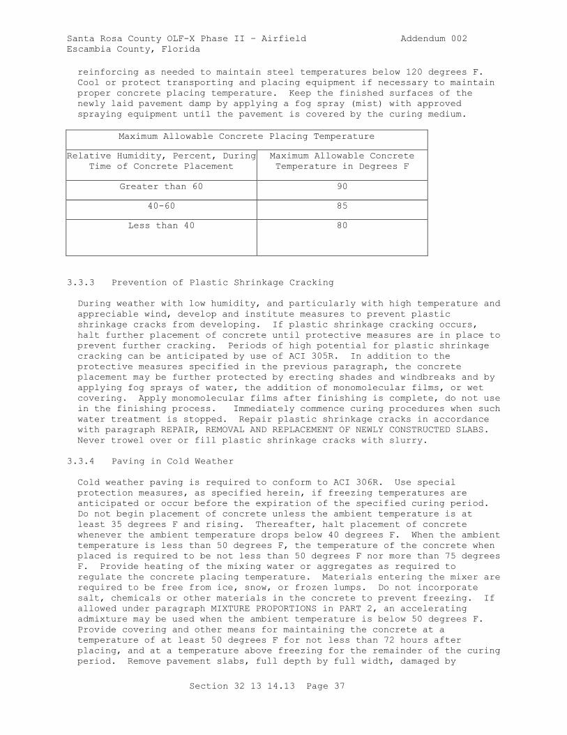
Santa Rosa County OLF-X Phase II – Airfield Addendum 002
Escambia County, Florida
Section 32 13 14.13 Page 37
reinforcing as needed to maintain steel temperatures below 120 degrees F.
Cool or protect transporting and placing equipment if necessary to maintain
proper concrete placing temperature. Keep the finished surfaces of the
newly laid pavement damp by applying a fog spray (mist) with approved
spraying equipment until the pavement is covered by the curing medium.
Maximum Allowable Concrete Placing Temperature
Relative Humidity, Percent, During
Time of Concrete Placement
Maximum Allowable Concrete
Temperature in Degrees F
Greater than 60 90
40-60 85
Less than 40 80
3.3.3 Prevention of Plastic Shrinkage Cracking
During weather with low humidity, and particularly with high temperature and
appreciable wind, develop and institute measures to prevent plastic
shrinkage cracks from developing. If plastic shrinkage cracking occurs,
halt further placement of concrete until protective measures are in place to
prevent further cracking. Periods of high potential for plastic shrinkage
cracking can be anticipated by use of ACI 305R. In addition to the
protective measures specified in the previous paragraph, the concrete
placement may be further protected by erecting shades and windbreaks and by
applying fog sprays of water, the addition of monomolecular films, or wet
covering. Apply monomolecular films after finishing is complete, do not use
in the finishing process. Immediately commence curing procedures when such
water treatment is stopped. Repair plastic shrinkage cracks in accordance
with paragraph REPAIR, REMOVAL AND REPLACEMENT OF NEWLY CONSTRUCTED SLABS.
Never trowel over or fill plastic shrinkage cracks with slurry.
3.3.4 Paving in Cold Weather
Cold weather paving is required to conform to ACI 306R. Use special
protection measures, as specified herein, if freezing temperatures are
anticipated or occur before the expiration of the specified curing period.
Do not begin placement of concrete unless the ambient temperature is at
least 35 degrees F and rising. Thereafter, halt placement of concrete
whenever the ambient temperature drops below 40 degrees F. When the ambient
temperature is less than 50 degrees F, the temperature of the concrete when
placed is required to be not less than 50 degrees F nor more than 75 degrees
F. Provide heating of the mixing water or aggregates as required to
regulate the concrete placing temperature. Materials entering the mixer are
required to be free from ice, snow, or frozen lumps. Do not incorporate
salt, chemicals or other materials in the concrete to prevent freezing. If
allowed under paragraph MIXTURE PROPORTIONS in PART 2, an accelerating
admixture may be used when the ambient temperature is below 50 degrees F.
Provide covering and other means for maintaining the concrete at a
temperature of at least 50 degrees F for not less than 72 hours after
placing, and at a temperature above freezing for the remainder of the curing
period. Remove pavement slabs, full depth by full width, damaged by
Santa Rosa County OLF-X Phase II – Airfield Addendum 002
Escambia County, Florida
Section 32 13 14.13 Page 38
freezing or falling below freezing temperature to the nearest planned joint,
and replace as specified in paragraph REPAIR, REMOVAL AND REPLACEMENT OF
NEWLY CONSTRUCTED SLABS, at no expense to the Owner.
3.4 CONCRETE PRODUCTION
Provide batching, mixing, and transporting equipment with a capacity
sufficient to maintain a continuous, uniform forward movement of the paver
of not less than 2.5 feet per minute. Deposit concrete transported in non-
agitating equipment in front of the paver within 45 minutes from the time
cement has been charged into the mixing drum, except that if the ambient
temperature is above 90 degrees F, the time is reduced to 30 minutes.
Deposit concrete transported in truck mixers in front of the paver within 90
minutes from the time cement has been charged into the mixer drum of the
plant or truck mixer. If the ambient temperature is above 90 degrees F, the
time is reduced to 60 minutes. Accompany every load of concrete delivered
to the paving site with a batch ticket from the operator of the batching
plant. Provide batch ticket information required by ASTM C94/C94M on
approved forms. In addition provide design quantities in mass or volume for
all materials, batching tolerances of all materials, and design and actual
water cementitious materials ratio on each batch delivered, and the time of
day. Provide batch tickets for each truck delivered as part of the lot
acceptance package to the placing foreman to maintain on file and deliver
them to the Owner weekly.
3.4.1 Batching and Mixing Concrete
Maintain scale pivots and bearings clean and free of rust. Remove any
equipment which fails to perform as specified immediately from use until
properly repaired and adjusted, or replaced.
3.4.2 Transporting and Transfer - Spreading Operations
Operate non-agitating equipment only on smooth roads and for haul time less
than 15 minutes. Deposit concrete as close as possible to its final
position in the paving lane. Operate all equipment to discharge and
transfer concrete without segregation. Dumping of concrete in discrete
piles is not permitted. No transfer or spreading operation which requires
the use of front-end loaders, dozers, or similar equipment to distribute the
concrete are permitted.
3.5 PAVING
3.5.1 General Requirements
Construct pavement with paving and finishing equipment utilizing rigid fixed
forms or by use of slipform paving equipment. Provide paving and finishing
equipment and procedures capable of constructing paving lanes of the
required width at a rate of at least 2.5 feet of paving lane per minute on a
routine basis. Control paving equipment and its operation, and coordinated
with all other operations, such that the paver-finisher has a continuous
forward movement at a reasonably uniform speed from beginning to end of each
paving lane, except for inadvertent equipment breakdown. Backing the paver
and refinishing a lane is not permitted. Remove and replace concrete
refinished in this manner. Failure to achieve a continuous forward motion
requires halting operations, regrouping, and modifying operations to achieve
this requirement. Personnel are not permitted to walk or operate in the
Santa Rosa County OLF-X Phase II – Airfield Addendum 002
Escambia County, Florida
Section 32 13 14.13 Page 39
plastic concrete at any time. Where an open-graded granular base is
required under the concrete, select paving equipment and procedures which
operate properly on the base course without causing displacement or other
damage.
3.5.2 Consolidation
Consolidate concrete with the specified type of lane-spanning, gang-mounted,
mechanical, immersion type vibrating equipment mounted in front of the
paver, supplemented, in rare instances as specified, by hand-operated
vibrators. Insert vibrators into the concrete to a depth that provides the
best full-depth consolidation but not closer to the underlying material than
2 inches. Excessive vibration is not permitted. Discontinue paving
operations if vibrators cause visible tracking in the paving lane, until
equipment and operations have been modified to prevent it. Vibrate concrete
in small, odd-shaped slabs or in isolated locations inaccessible to the
gang-mounted vibration equipment with an approved hand-operated immersion
vibrator operated from a bridge spanning the area. Do not use vibrators to
transport or spread the concrete. Do not operate hand-operated vibrators in
the concrete at one location for more than 20 seconds. Insert hand-operated
vibrators between 6 to 15 inches on centers. For each paving train, provide
at least one additional vibrator spud, or sufficient parts for rapid
replacement and repair of vibrators at the paving site at all times. Any
evidence of inadequate consolidation (honeycomb along the edges, large air
pockets, or any other evidence) requires the immediate stopping of the
paving operation and approved adjustment of the equipment or procedures.
3.5.3 Operation
When the paver approaches a header at the end of a paving lane, maintain a
sufficient amount of concrete ahead of the paver to provide a roll of
concrete which spills over the header. Provide a sufficient amount of extra
concrete to prevent any slurry that is formed and carried along ahead of the
paver from being deposited adjacent to the header. Maintain the spud
vibrators in front of the paver at the desired depth as close to the header
as possible before they are lifted. Provide additional consolidation
adjacent to the headers by hand-manipulated vibrators. When the paver is
operated between or adjacent to previously constructed pavement (fill-in
lanes), provide provisions to prevent damage to the previously constructed
pavement. Electronically control screeds or extrusion plates from the
previously placed pavement so as to prevent them from applying pressure to
the existing pavement and to prevent abrasion of the pavement surface.
Maintain the overlapping area of existing pavement surface completely free
of any loose or bonded foreign material as the paver-finisher operates
across it. When the paver travels on existing pavement, maintain approved
provisions to prevent damage to the existing pavement. Pavers using
transversely oscillating screeds are not allowed to form fill-in lanes that
have widths less than a full width for which the paver was designed or
adjusted.
3.5.4 Required Results
Adjust and operate the paver-finisher, its gang-mounted vibrators and
operating procedures coordinated with the concrete mixture being used, to
produce a thoroughly consolidated slab throughout that is true to line and
grade within specified tolerances. Provide a paver-finishing operation that
produces a surface finish free of irregularities, tears, voids of any kind,
Santa Rosa County OLF-X Phase II – Airfield Addendum 002
Escambia County, Florida
Section 32 13 14.13 Page 40
and any other discontinuities in a single pass across the pavement; multiple
passes are not permitted. Provide equipment and its operation that produce
a finished surface requiring no hand finishing other than the use of cutting
straightedges, except in very infrequent instances. Stop paving if any
equipment or operation fails to produce the above results. Prior to
recommencing paving, properly adjust or replace the equipment, modify the
operation, or modify the mixture proportions, in order to produce the
required results. No water, other than fog sprays (mist) as specified in
paragraph PREVENTION OF PLASTIC SHRINKAGE CRACKING above, is allowed to be
applied to the concrete or the concrete surface during paving and finishing.
3.5.5 Fixed Form Paving
Provide paving equipment for fixed-form paving and the operation that
conforms to the requirements of paragraph EQUIPMENT, and all requirements
specified herein.
3.5.5.1 Forms for Fixed-Form Paving
a. Provide straight forms made of steel and in sections not less than 10
feet in length that are clean and free of rust or other contaminants.
Seal any holes or perforations in forms prior to paving unless
otherwise permitted. Maintain forms in place and passable by all
equipment necessary to complete the entire paving operation without
need to remove horizontal form supports. Provide flexible or curved
forms of proper radius for curves of 100-foot radius or less. Provide
wood forms for curves and fillets made of well-seasoned, surfaced plank
or plywood, straight, and free from warp or bend that have adequate
strength and are rigidly braced. Provide forms with a depth equal to
the pavement thickness at the edge. Where the project requires several
different slab thicknesses, forms may be built up by bolting or welding
a tubular metal section or by bolting wood planks to the bottom of the
form to completely cover the underside of the base of the form and
provide an increase in depth of not more than 25 percent. Provide
forms with the base width of the one-piece or built-up form not less
than eight-tenths of the vertical height of the form, except provide
forms 8 inches or less in vertical height with a base width not less
than the vertical height of the form. Provide forms with maximum
vertical deviation of top of any side form, including joints, not
varying from a true plane more than 1/8 inch in 10 feet, and the
upstanding leg not varying more than 1/4 inch.
b. Provide form sections that are tightly locked and free from play or
movement in any direction. Provide forms with adequate devices for
secure settings so that when in place they withstand, without visible
spring or settlement, the impact and vibration of the consolidating and
finishing equipment.
c. Set forms for full bearing on foundation for entire length and width
and in alignment with edge of finished pavement. Support forms during
entire operation of placing, compaction, and finishing so that forms do
not deviate vertically more than 0.01 foot from required grade and
elevations indicated. Check conformity to the alignment and grade
elevations shown on the drawings and make necessary corrections
immediately prior to placing the concrete. Clean and oil the forms
each time before concrete is placed. Concrete placement is not allowed
until setting of forms has been checked and approved by the CQC team.
Santa Rosa County OLF-X Phase II – Airfield Addendum 002
Escambia County, Florida
Section 32 13 14.13 Page 41
d. Do not anchor guide rails for fixed form pavers into new concrete or
existing concrete to remain.
3.5.5.2 Form Removal
Keep forms in place at least 12 hours after the concrete has been placed.
When conditions are such that the early strength gain of the concrete is
delayed, leave the forms in place for a longer time, as directed. Remove
forms by procedures that do not damage the concrete. Do not use bars or
heavy metal tools directly against the concrete in removing the forms.
Promptly repair any concrete found to be defective after form removal, using
procedures specified or as directed.
3.5.6 Slipform Paving
3.5.6.1 General
Provide paving equipment for slipform paving and the operation thereof that
conforms to the requirement of paragraph EQUIPMENT, and all requirements
specified herein. Provide a slipform paver capable of shaping the concrete
to the specified and indicated cross section, meeting all tolerances, with a
surface finish and edges that require only a very minimum isolated amount of
hand finishing, in one pass. If the paving operation does not meet the
above requirements and the specified tolerances, immediately stop the
operation, and regroup and replace or modify any equipment as necessary,
modify paving procedures or modify the concrete mix, in order to resolve the
problem. Provide a slipform paver that is automatically electronically
controlled from a taut wire guideline for horizontal alignment and on both
sides from a taut wire guideline for vertical alignment, except that
electronic control from a ski operating on a previously constructed
adjoining lane is requied where applicable for either or both sides.
Automatic, electronic controls are required for vertical alignment on both
sides of the lane. Control from a slope-adjustment control or control
operating from the underlying material is not allowed. Properly adjust side
forms on slipform pavers so that the finished edge of the paving lane meets
all specified tolerances. Install dowels in longitudinal construction
joints as specified below. The installation of these dowels by dowel
inserters attached to the paver or by any other means of inserting the
dowels into the plastic concrete is not permitted.
3.5.6.2 Guideline for Slipform Paving
Accurately and securely install guidelines well in advance of concrete
placement. Provide supports at necessary intervals to eliminate all sag in
the guideline when properly tightened. Provide guideline consisting of high
strength wire set with sufficient tension to remove all sag between
supports. Provide supports that are securely staked to the underlying
material or other provisions made to ensure that the supports are not
displaced when the guideline is tightened or when the guideline or supports
are accidentally touched by workmen or equipment during construction.
Provide appliances for attaching the guideline to the supports that are
capable of easy adjustment in both the horizontal and vertical directions.
When it is necessary to leave gaps in the guideline to permit equipment to
use or cross underlying material, provide provisions for quickly and
accurately replacing the guideline without any delay to the forward progress
of the paver. Provide supports on either side of the gap that are secured
Santa Rosa County OLF-X Phase II – Airfield Addendum 002
Escambia County, Florida
Section 32 13 14.13 Page 42
in such a manner as to avoid disturbing the remainder of the guideline when
the portion across the gap is positioned and tightened. Check the guideline
across the gap and adjacent to the gap for a distance of 200 feet for
horizontal and vertical alignment after the guideline across the gap is
tightened. Provide vertical and horizontal positioning of the guideline
such that the finished pavement conforms to the alignment and grade
elevations shown on the drawings within the specified tolerances for grade
and smoothness. The specified tolerances are intended to cover only the
normal deviations in the finished pavement that may occur under good
supervision and do not apply to setting of the guideline. Set the guideline
true to line and grade.
3.5.6.3 Stringless Technology
If the use of any type of stringless technology is proposed, submit a
detailed description of the system and perform a trial field demonstration
at least one week prior to start of paving. Approval of the control system
will be based on the results of the demonstration and on continuing
satisfactory operation during paving.
3.5.7 Placing Reinforcing Steel
Provide the type and amount of steel reinforcement indicated.
3.5.7.1 Pavement Thickness Greater Than 12 inches
For pavement thickness of 12 inches or more, install the reinforcement steel
by the strike-off method wherein a layer of concrete is deposited on the
underlying material, consolidated, and struck to the indicated elevation of
the steel reinforcement. Place the reinforcement upon the pre-struck
surface, followed by placement of the remaining concrete and finishing in
the required manner. When placement of the second lift causes the steel to
be displaced horizontally from its original position, provide provisions for
increasing the thickness of the first lift and depressing the reinforcement
into the unhardened concrete to the required elevation. Limit the increase
in thickness only as necessary to permit correct horizontal alignment to be
maintained. Remove and replace any portions of the bottom layer of concrete
that have been placed more than 30 minutes without being covered with the
top layer with newly mixed concrete without additional cost to the Owner.
3.5.7.2 Pavement Thickness Less Than 12 Inches
For pavements less than 12 inches thick, position the reinforcement on
suitable chairs or continuous mesh support devices securely fastened to the
subgrade prior to concrete placement. Consolidate concrete after the steel
has been placed. Regardless of placement procedure, provide reinforcing
steel free from coatings which could impair bond between the steel and
concrete, with reinforcement laps as indicated. Regardless of the equipment
or procedures used for installing reinforcement, ensure that the entire
depth of concrete is adequately consolidated.
3.5.8 Placing Dowels and Tie Bars
Ensure the method used to install and hold dowels in position result in
dowel alignment within the maximum allowed horizontal and vertical tolerance
of 1/8 inch per foot after the pavement has been completed. Except as
otherwise specified below, maintain the horizontal spacing of dowels within
Santa Rosa County OLF-X Phase II – Airfield Addendum 002
Escambia County, Florida
Section 32 13 14.13 Page 43
a tolerance of plus or minus 5/8 inch. Locate the dowel vertically on the
face of the slab within a tolerance of plus or minus 1/2 inch). Measure the
vertical alignment of the dowels parallel to the designated top surface of
the pavement, except for those across the crown or other grade change
joints. Measure dowels across crowns and other joints at grade changes to a
level surface. Check horizontal alignment perpendicular to the joint edge
with a framing square. Do not place longitudinal dowels and tie bars
closer than 0.6 times the dowel bar tie bar length to the planned joint
line. If the last regularly spaced longitudinal dowel tie bar is closer
than that dimension, move it away from the joint to a location 0.6 times the
dowel bar tie bar length, but not closer than 6 inches to its nearest
neighbor. Resolve dowel (tie bar) interference at a transverse joint-
longitudinal joint intersection by deleting the closest transverse dowel
(tie bar). Do not position the end of a transverse dowel closer than 12
inches from the end of the nearest longitudinal dowel. Install dowels as
specified in the following subparagraphs.
3.5.8.1 Contraction Joints
Securely hold dowels and tie bars in longitudinal and transverse contraction
joints within the paving lane in place, as indicated, by means of rigid
metal frames or basket assemblies of an approved type. Securely hold the
basket assemblies in the proper location by means of suitable pins or
anchors. Do not cut or crimp the dowel basket tie wires.
3.5.8.2 Construction Joints-Fixed Form Paving
Install dowels and tie bars by the bonded-in-place method or the drill-and-
dowel method. Installation by removing and replacing in preformed holes is
not permitted. Prepare and place dowels and tie bars across joints where
indicated, correctly aligned, and securely held in the proper horizontal and
vertical position during placing and finishing operations, by means of
devices fastened to the forms. Provide the spacing of dowels and tie bars
in construction joints as indicated, except that, where the planned spacing
cannot be maintained because of form length or interference with form
braces, provide closer spacing with additional dowels or tie bars.
3.5.8.3 Dowels Installed in Hardened Concrete
Install dowels in hardened concrete by bonding the dowels into holes drilled
into the hardened concrete. Before drilling commences, cure the concrete
for 7 days or until it has reached a minimum . Drill holes 1/8 inch greater
in diameter than the dowels into the hardened concrete using rotary-core
drills. Rotary-percussion drills are permitted, provided that excessive
spalling does not occur to the concrete joint face. Excessive spalling is
defined as spalling deeper than 1/4 inch from the joint face or 1/2 inch
radially from the outside of the drilled hole. Continuing damage requires
modification of the equipment and operation. Drill depth of dowel hole
within a tolerance of plus or minus 1/2 inch of the dimension shown on the
drawings. Upon completion of the drilling operation, blow out the dowel
hole with oil-free, compressed air. Bond dowels in the drilled holes using
epoxy resin. Inject epoxy resin at the back of the hole before installing
the dowel and extruded to the collar during insertion of the dowel so as to
completely fill the void around the dowel. Application by buttering the
dowel is not permitted. Hold the dowels in alignment at the collar of the
hole, after insertion and before the grout hardens, by means of a suitable
metal or plastic grout retention ring fitted around the dowel. Provide
Santa Rosa County OLF-X Phase II – Airfield Addendum 002
Escambia County, Florida
Section 32 13 14.13 Page 44
dowels required between new and existing concrete in holes drilled in the
existing concrete, all as specified above. Where tie bars are required in
longitudinal construction joints of slipform pavement, install bent tie bars
at the paver, in front of the transverse screed or extrusion plate. Do not
install tie bars in preformed holes. Construct a standard keyway, with the
bent tie bars inserted into the plastic concrete through a 26 gauge thick
metal keyway liner. Protect and maintain the keyway liner to remain in
place and become part of the joint. When bending tie bars, provide the
radius of bend not be less than the minimum recommended for the particular
grade of steel in the appropriate material standard. Before placement of
the adjoining paving lane, straighten the tie bars using procedures which do
not spall the concrete around the bar.
3.5.8.4 Lubricating Dowel Bars
Wipe the portion of each dowel intended to move within the concrete clean
and coat with a thin, even film of lubricating oil or light grease before
the concrete is placed.
3.6 FINISHING
Provide finishing operations as a continuing part of placing operations
starting immediately behind the strike-off of the paver. Provide initial
finishing by the transverse screed or extrusion plate. Provide the sequence
of operations consisting of transverse finishing, longitudinal machine
floating if used, straightedge finishing, texturing, and then edging of
joints. Provide finishing by the machine method. Provide a work bridge as
necessary for consolidation and hand finishing operations. Use the hand
method only on isolated areas of odd slab widths or shapes and in the event
of a breakdown of the mechanical finishing equipment. Keep supplemental
hand finishing for machine finished pavement to an absolute minimum.
Immediately stop any machine finishing operation which requires appreciable
hand finishing, other than a moderate amount of straightedge finishing.
Prior to recommencing machine finishing, properly adjust or replace the
equipment. Immediately halt any operations which produce more than 1/8 inch
of mortar-rich surface (defined as deficient in plus U.S. No. 4 sieve size
aggregate) and the equipment, mixture, or procedures modified as necessary.
Compensate for surging behind the screeds or extrusion plate and settlement
during hardening and take care to ensure that paving and finishing machines
are properly adjusted so that the finished surface of the concrete (not just
the cutting edges of the screeds) is at the required line and grade.
Maintain finishing equipment and tools clean and in an approved condition.
Water is not allowed to be added to the surface of the slab with the
finishing equipment or tools, or in any other way, except for fog (mist)
sprays specified to prevent plastic shrinkage cracking.
3.6.1 Machine Finishing With Fixed Forms
Replace machines that cause displacement of the forms. Only one pass of the
finishing machine is allowed over each area of pavement. If the equipment
and procedures do not produce a surface of uniform texture, true to grade,
in one pass, immediately stop the operation and the equipment, mixture, and
procedures adjusted as necessary.
3.6.2 Machine Finishing with Slipform Pavers
Santa Rosa County OLF-X Phase II – Airfield Addendum 002
Escambia County, Florida
Section 32 13 14.13 Page 45
Operate the slipform paver so that only a very minimum of additional
finishing work is required to produce pavement surfaces and edges meeting
the specified tolerances. Immediately modify or replace any equipment or
procedure that fails to meet these specified requirements as necessary. A
self-propelled non-rotating pipe float may be used while the concrete is
still plastic, to remove minor irregularities and score marks. Only one
pass of the pipe float is allowed. If there is concrete slurry or fluid
paste on the surface that runs over the edge of the pavement, immediately
stop the paving operation and the equipment, mixture, or operation modified
to prevent formation of such slurry. Immediately remove any slurry which
does run down the vertical edges by hand, using stiff brushes or scrapers.
Slurry, concrete or concrete mortar is not allowed to build up along the
edges of the pavement to compensate for excessive edge slump, either while
the concrete is plastic or after it hardens.
3.6.3 Surface Correction and Testing
After all other finishing is completed but while the concrete is still
plastic, eliminate minor irregularities and score marks in the pavement
surface by means of cutting straightedges. Provide cutting straightedges
with a minimum length of 12 feet that are operated from the sides of the
pavement or from bridges. Provide cutting straightedges operated from the
side of the pavement equipped with a handle 3 feet longer than one-half the
width of the pavement. Test the surface for trueness with a straightedge
held in successive positions parallel and at right angles to the center line
of the pavement, and the whole area covered as necessary to detect
variations. Advance the straightedge along the pavement in successive
stages of not more than one-half the length of the straightedge.
Immediately fill depressions with freshly mixed concrete, strike off,
consolidate with an internal vibrator, and refinish. Strike off projections
above the required elevation and refinish. Continue the straightedge
testing and finishing until the entire surface of the concrete is free from
observable departure from the straightedge and conforms to the surface
requirements specified in paragraph SURFACE SMOOTHNESS. This straightedging
is not allowed to be used as a replacement for the straightedge testing of
paragraph SURFACE SMOOTHNESS in PART 1. Use long-handled, flat bull floats
very sparingly and only as necessary to correct minor, scattered surface
defects. If frequent use of bull floats is necessary, stop the paving
operation and the equipment, mixture or procedures adjusted to eliminate the
surface defects. Keep finishing with hand floats and trowels to the
absolute minimum necessary. Take extreme care to prevent over finishing
joints and edges. Produce the surface finish of the pavement essentially by
the finishing machine and not by subsequent hand finishing operations. All
hand finishing operations are subject to approval.
3.6.4 Hand Finishing
Use hand finishing operations only as specified below. Provide a work
bridge to be used as necessary for consolidation and placement operations to
avoid standing in concrete.
3.6.4.1 Equipment and Template
In addition to approved mechanical internal vibrators for consolidating the
concrete, provide a strike-off and tamping template and a longitudinal float
for hand finishing. Provide a template at least 1 foot longer than the
width of pavement being finished, of an approved design, and sufficiently

Santa Rosa County OLF-X Phase II – Airfield Addendum 002
Escambia County, Florida
Section 32 13 14.13 Page 46
rigid to retain its shape, that is constructed of metal or other suitable
material shod with metal. Provide a longitudinal float at least 10 feet
long, of approved design, is rigid and substantially braced, and maintain a
plane surface on the bottom. Grate tampers (jitterbugs) are not allowed.
3.6.4.2 Finishing and Floating
As soon as placed and vibrated, strike off the concrete and screeded to the
crown and cross section and to such elevation above grade that when
consolidated and finished, the surface of the pavement is at the required
elevation. In addition to previously specified complete coverage with
handheld immersion vibrators, tamp the entire surface with the strike-off
and tamping template, and the tamping operation continued until the required
compaction and reduction of internal and surface voids are accomplished.
Immediately following the final tamping of the surface, float the pavement
longitudinally from bridges resting on the side forms and spanning but not
touching the concrete. If necessary, place additional concrete,
consolidated and screeded, and the float operated until a satisfactory
surface has been produced. Do not advance the floating operation more than
half the length of the float and then continued over the new and previously
floated surfaces.
3.6.5 Texturing
Before the surface sheen has disappeared and before the concrete hardens or
curing compound is applied, texture the surface of the pavement as described
herein. After curing is complete, thoroughly power broom all textured
surfaces to remove all debris.
3.6.5.1 Burlap Drag Surface
Apply surface texture by dragging the surface of the pavement, in the
direction of the concrete placement, with an approved burlap drag. Operate
the drag with the fabric moist, and the fabric maintained clean or changed
as required to keep clean. Perform the dragging so as to produce a uniform
finished surface having a fine sandy texture without disfiguring marks.
3.6.6 Edging
Before texturing has been completed, carefully finish the edge of the slabs
along the forms, along the edges of slipformed lanes, and at the joints with
an edging tool to form a smooth rounded surface of 1/8 inch radius.
Eliminate tool marks, and provide edges that are smooth and true to line.
Water is not allowed to be added to the surface during edging. Take extreme
care to prevent overworking the concrete.
3.6.7 Outlets in Pavement
Construct recesses for the tie-down anchors, lighting fixtures, and other
outlets in the pavement to conform to the details and dimensions shown.
Carefully finish the concrete in these areas to provide a surface of the
same texture as the surrounding area that is within the requirements for
plan grade and surface smoothness.
3.7 CURING
Santa Rosa County OLF-X Phase II – Airfield Addendum 002
Escambia County, Florida
Section 32 13 14.13 Page 47
3.7.1 Protection of Concrete
Continuously protect concrete against loss of moisture and rapid temperature
changes for at least 7 days from the completion of finishing operations.
Have all equipment needed for adequate curing and protection of the concrete
on hand and ready for use before actual concrete placement begins. If any
selected method of curing does not afford the proper curing and protection
against concrete cracking, remove or replace the damaged pavement, and
provide another method of curing as directed. Accomplish curing by one of
the following methods.
3.7.2 Membrane Curing
Apply a uniform coating of white-pigmented, membrane-forming, curing
compound to the entire exposed surface of the concrete as soon as the free
water has disappeared from the surface after moist curing ceases. Apply
immediately along the formed edge faces after the forms are removed. Do not
allow the concrete to dry before the application of the membrane. If any
drying has occurred, moisten the surface of the concrete with a fine spray
of water, and the curing compound applied as soon as the free water
disappears. Apply the curing compound to the finished surfaces by means of
an approved automatic spraying machine. Apply the curing compound with a
single overlapping application that provides a uniform coverage of 150
square feet per gallon. The application of curing compound by hand-
operated, mechanical powered pressure sprayers is permitted only on odd
widths or shapes of slabs and on concrete surfaces exposed by the removal of
forms. When the application is made by hand-operated sprayers, apply a
second coat in a direction approximately at right angles to the direction of
the first coat. If pinholes, abrasions, or other discontinuities exist,
apply an additional coat to the affected areas within 30 minutes. Respray
curing compound to concrete surfaces that are subjected to heavy rainfall
within 3 hours after the curing compound has been applied by the method and
at the coverage specified above. Respray curing compound to areas where the
curing compound is damaged by subsequent construction operations within the
curing period immediately. Adequately protect concrete surfaces to which
membrane-curing compounds have been applied during the entire curing period
from pedestrian and vehicular traffic, except as required for joint-sawing
operations and surface tests, and from any other possible damage to the
continuity of the membrane.
3.7.3 Moist Curing
Maintain concrete to be moist-cured continuously wet for the entire curing
period, or until curing compound is applied, commencing immediately after
finishing. If forms are removed before the end of the curing period,
provide curing on unformed surfaces, using suitable materials. Cure
surfaces by ponding, by continuous sprinkling, by continuously saturated
burlap or cotton mats, or by continuously saturated plastic coated burlap.
Provide burlap and mats that are clean and free from any contamination and
completely saturated before being placed on the concrete. Lap sheets to
provide full coverage. Provide an approved work system to ensure that moist
curing is continuous 24 hours per day and that the entire surface is wet.
3.8 JOINTS
3.8.1 General Requirements for Joints
Santa Rosa County OLF-X Phase II – Airfield Addendum 002
Escambia County, Florida
Section 32 13 14.13 Page 48
Construct joints that conform to the locations and details indicated and are
perpendicular to the finished grade of the pavement. Provide joints that
are straight and continuous from edge to edge or end to end of the pavement
with no abrupt offset and no gradual deviation greater than 1/2 inch. Where
any joint fails to meet these tolerances, remove and replace the slabs
adjacent to the joint at no additional cost to the Owner. Change from the
jointing pattern shown on the drawings is not allowed without written
approval. Seal joints immediately following curing of the concrete or as
soon thereafter as weather conditions permit as specified in Section 32 01
19 FIELD MOLDED SEALANTS FOR SEALING JOINTS IN RIGID PAVEMENTS.
3.8.2 Longitudinal Construction Joints
Install dowels or tie bars in the longitudinal construction joints, or
thicken the edges as indicated. Install dowels tie bars as specified above.
After the end of the curing period, saw longitudinal construction joints to
provide a groove at the top for sealant conforming to the details and
dimensions indicated.
3.8.3 Transverse Construction Joints
Install transverse construction joints at the end of each day's placing
operations and at any other points within a paving lane when concrete
placement is interrupted for 30 minutes or longer. Install the transverse
construction joint at a planned transverse joint. Provide transverse
construction joints by utilizing headers or by paving through the joint,
then full-depth sawcutting the excess concrete. Construct pavement with the
paver as close to the header as possible, with the paver run out completely
past the header. Provide transverse construction joints at a planned
transverse joint constructed as shown or, if not shown otherwise, dowelled
in accordance with paragraph DOWELS INSTALLED IN HARDENED CONCRETE, or
paragraph FIXED FORM PAVING above.
3.8.4 Expansion Joints
Provide expansion joints where indicated, and about any structures and
features that project through or into the pavement, using joint filler of
the type, thickness, and width indicated, and installed to form a complete,
uniform separation between the structure and the pavement or between two
pavements. Attach the filler to the original concrete placement with
adhesive and mechanical fasteners and extend the full slab depth. After
placement and curing of the adjacent slab, sawcut the sealant reservoir
depth from the filler. Tightly fit adjacent sections of filler together,
with the filler extending across the full width of the paving lane or other
complete distance in order to prevent entrance of concrete into the
expansion space. Finish edges of the concrete at the joint face with an
edger with a radius of 1/8 inch.
3.8.5 Slip Joints
Install slip joints where indicated using the specified materials. Attach
preformed joint filler material to the face of the original concrete
placement with adhesive and mechanical fasteners. Construct a 3/4 inch deep
reservoir for joint sealant at the top of the joint. Finish edges of the
joint face with an edger with a radius of 1/8 inch.
Santa Rosa County OLF-X Phase II – Airfield Addendum 002
Escambia County, Florida
Section 32 13 14.13 Page 49
3.8.6 Contraction Joints
Construct transverse and longitudinal contraction joints by sawing an
initial groove in the concrete with a 1/8 inch blade to the indicated depth.
During sawing of joints, and again 24 hours later, the CQC team is required
to inspect all exposed lane edges for development of cracks below the saw
cut, and immediately report results. If there are more than six consecutive
uncracked joints after 48 hours, saw succeeding joints 25 percent deeper
than originally indicated at no additional cost to the Owner. The time of
initial sawing varies depending on existing and anticipated weather
conditions and be such as to prevent uncontrolled cracking of the pavement.
Commence sawing of the joints as soon as the concrete has hardened
sufficiently to permit cutting the concrete without chipping, spalling, or
tearing. The sawed faces of joints will be inspected for undercutting or
washing of the concrete due to the early sawing, and sawing delayed if
undercutting is sufficiently deep to cause structural weakness or excessive
roughness in the joint. Continue the sawing operation as required during
both day and night regardless of weather conditions. Saw the joints at the
required spacing consecutively in the sequence of the concrete placement.
Provide adequate lighting for night work. Illumination using vehicle
headlights is not permitted. Provide a chalk line or other suitable guide
to mark the alignment of the joint. Before sawing a joint, examine the
concrete closely for cracks, and do not saw the joint if a crack has
occurred near the planned joint location. Discontinue sawing if a crack
develops ahead of the saw cut. Immediately after the joint is sawed,
thoroughly flush the saw cut and adjacent concrete surface with water and
vacuumed until all waste from sawing is removed from the joint and adjacent
concrete surface. Take necessary precautions to insure that the concrete is
properly protected from damage and cured at sawed joints. Tightly seal the
top of the joint opening and the joint groove at exposed edges with cord
backer rod before the concrete in the region of the joint is resprayed with
curing compound, and be maintained until removed immediately before sawing
the joint sealant reservoir. Respray the surface with curing compound as
soon as free water disappears. Seal the exposed saw cuts on the faces of
pilot lanes with bituminous mastic or masking tape. After expiration of the
curing period, widen the upper portion of the groove by sawing with ganged
diamond saw blades to the width and depth indicated for the joint sealer.
Center the reservoir over the initial sawcut.
3.8.7 Thickened Edge Joints
Construct thickened edge joints as indicated on the drawings. Grade the
underlying material in the transition area as shown and meet the
requirements for smoothness and compaction specified for all other areas of
the underlying material.
3.9 REPAIR, REMOVAL AND REPLACEMENT OF NEWLY CONSTRUCTED SLABS
3.9.1 General Criteria
Repair or remove and replace new pavement slabs as specified at no cost to
the Owner. Removal of partial slabs is not permitted. Prior to any
repairs, submit a Repair Recommendations Plan detailing areas exceeding the
specified limits as well as repair recommendations required to bring these
areas within specified tolerances.
Santa Rosa County OLF-X Phase II – Airfield Addendum 002
Escambia County, Florida
Section 32 13 14.13 Page 50
3.9.2 Slabs with Cracks
The Owner may require cores to be taken over cracks to determine depth of
cracking. Such cores are to be drilled with a minimum diameter of 6 inches,
and be backfilled with an approved non-shrink concrete. Perform drilling of
cores and filling of holes at no expense to the Owner. Clean cracks that do
not exceed 2 inches in depth; then pressure injected full depth with epoxy
resin, Type IV, Grade 1. Remove and replace slabs containing cracks deeper
than 2 inches.
3.9.3 Removal and Replacement of Full Slabs
Remove and replace slabs containing more than 15.0 percent of any
longitudinal or transverse joint edge spalled. Where it is necessary to
remove full slabs, remove in accordance with paragraph REMOVAL OF EXISTING
PAVEMENT SLAB below. Remove and replace full depth, by full width of the
slab, and the limit of removal normal to the paving lane and extend to each
original joint. Compact and shape the underlying material as specified in
the appropriate section of these specifications, and clean the surfaces of
all four joint faces of all loose material and contaminants and coated with
a double application of membrane forming curing compound as bond breaker.
Install dowels of the size and spacing as specified for other joints in
similar pavement by epoxy grouting them into holes drilled into the existing
concrete using procedures as specified in paragraph PLACING DOWELS AND TIE
BARS, above. Provide dowels for all four edges of the new slab. Cut off
original damaged dowels or tie bars flush with the joint face. Lightly oil
or grease protruding portions of new dowels. Place concrete as specified
for original construction. Take care to prevent any curing compound from
contacting dowels or tie bars. Prepare and seal the resulting joints around
the new slab as specified for original construction.
3.9.4 Repairing Spalls Along Joints
Repair spalls along joints to be sealed to a depth to restore the full
joint-face support prior to placing adjacent pavement. Where directed,
repair spalls along joints of new slabs, along edges of adjacent existing
concrete, and along parallel cracks by first making a vertical saw cut at
least 3 inches outside the spalled area and to a depth of at least 2 inches.
Provide saw cuts consisting of straight lines forming rectangular areas
without sawing beyond the intersecting saw cut. Chip out the concrete
between the saw cut and the joint, or crack, to remove all unsound concrete
and into at least 1/2 inch of visually sound concrete. Thoroughly clean the
cavity thus formed with high pressure water jets supplemented with oil-free
compressed air to remove all loose material. Immediately before filling the
cavity, apply a prime coat to the dry cleaned surface of all sides and
bottom of the cavity, except any joint face. Apply the prime coat in a thin
coating and scrubbed into the surface with a stiff-bristle brush. Provide
prime coat for portland cement repairs consisting of a neat cement grout and
for epoxy resin repairs consisting of epoxy resin, Type III, Grade 1. Fill
the prepared cavity with material identified in the following table based on
the cavity volume.
Spall Repairs
Volume of Prepared Cavity After
Removal Operations
Material
Santa Rosa County OLF-X Phase II – Airfield Addendum 002
Escambia County, Florida
Section 32 13 14.13 Page 51
Spall Repairs
less than 0.03 cubic foot epoxy resin mortar or epoxy resin or
latex modified mortar
0.03 cubic foot and 1/3 cubic foot Portland cement mortar
more than 1/3 cubic foot Portland cement concrete or latex
modified mortar
Provide portland cement concretes and mortars that consist of very low slump
mixtures, 1/2 inch slump or less, proportioned, mixed, placed, consolidated
by tamping, and cured, all as directed. Provide epoxy resin mortars made
with Type III, Grade 1, epoxy resin, using proportions and mixing and
placing procedures as recommended by the manufacturer and approved.
Proprietary patching materials may be used, subject to Owner approval.
Place the epoxy resin materials in the cavity in layers with a maximum
thickness of 2 inches. Provide adequate time between placement of
additional layers such that the temperature of the epoxy resin material does
not exceed 140 degrees F at any time during hardening. Provide mechanical
vibrators and hand tampers to consolidate the concrete or mortar. Remove
any repair material on the surrounding surfaces of the existing concrete
before it hardens. Where the spalled area abuts a joint, provide an insert
or other bond-breaking medium to prevent bond at the joint face. Saw a
reservoir for the joint sealant to the dimensions required for other joints.
Thoroughly clean the reservoir and then sealed with the sealer specified for
the joints. In lieu of sawing, spalls not adjacent to joints and popouts,
both less than 6 inches in maximum dimension, may be prepared by drilling a
core 2 inches in diameter greater than the size of the defect, centered over
the defect, and 2 inches deep or 1/2 inch into sound concrete, whichever is
greater. Repair the core hole as specified above for other spalls.
3.9.5 Repair of Weak Surfaces
Weak surfaces are defined as mortar-rich, rain-damaged, uncured, or
containing exposed voids or deleterious materials. Diamond grind slabs
containing weak surfaces less than 1/4 inch thick to remove the weak
surface. Diamond grind in accordance with paragraph DIAMOND GRINDING OF PCC
SURFACES in PART 1. All diamond ground areas are required to meet the
thickness, smoothness and grade criteria specified in PART 1 GENERAL.
Remove and replace slabs containing weak surfaces greater than 1/4 inch
thick.
3.9.6 Repair of Pilot Lane Vertical Faces
Repair excessive edge slump and joint face deformation in accordance with
paragraph EDGE SLUMP AND JOINT FACE DEFORMATION in PART 1. Repair
inadequate consolidation (honeycombing or air voids) by saw cutting the face
full depth along the entire lane length with a diamond blade. Obtain cores,
as directed, to determine the depth of removal.
3.10 EXISTING CONCRETE PAVEMENT REMOVAL AND REPAIR
Remove existing concrete pavement at locations indicated on the drawings.
Prior to commencing pavement removal operations, inventory the pavement
Santa Rosa County OLF-X Phase II – Airfield Addendum 002
Escambia County, Florida
Section 32 13 14.13 Page 52
distresses (cracks, spalls, and corner breaks) along the pavement edge to
remain. After pavement removal, survey the remaining edge again to quantify
any damage caused by removal operations. Perform both surveys in the
presence of the Owner. Perform repairs as indicated and as specified
herein. Carefully control all operations to prevent damage to the concrete
pavement and to the underlying material to remain in place. Perform all saw
cuts perpendicular to the slab surface, forming rectangular areas. Perform
all existing concrete pavement repairs prior to paving adjacent lanes.
3.10.1 Removal of Existing Pavement Slab
When existing concrete pavement is to be removed and adjacent concrete is to
be left in place, perform the first full depth saw cut on the joint between
the removal area and adjoining pavement to stay in place with a standard
diamond-type concrete saw. Next, perform a full depth saw cut parallel to
the joint that is at least 24 inches from the joint and at least 6 inches
from the end of any dowels with a diamond saw as specified in paragraph
SAWING EQUIPMENT. Remove all pavement beyond this last saw cut in
accordance with the approved demolition work plan. Remove all pavement
between this last saw cut and the joint line by carefully pulling pieces and
blocks away from the joint face with suitable equipment and then picking
them up for removal. In lieu of this method, this strip of concrete may be
carefully broken up and removed using hand-held jackhammers, 30 lb or less,
or other approved light-duty equipment which does not cause stress to
propagate across the joint saw cut and cause distress in the pavement which
is to remain in place. In lieu of the above specified removal method, the
slab may be sawcut full depth to divide it into several pieces and each
piece lifted out and removed. Use suitable equipment to provide a truly
vertical lift, and safe lifting devices used for attachment to the slab.
3.10.2 Edge Repair
Protect the edge of existing concrete pavement against which new pavement
abuts from damage at all times. Remove and replace slabs which are damaged
during construction as directed at no cost to the Owner. Repair of
previously existing damage areas is considered a subsidiary part of concrete
pavement construction. Saw off all exposed keys and keyways full depth.
3.10.2.1 Spall Repair
Not more than 15.0 percent of each slab's edge is allowed to be spalled.
Provide a full depth saw cut on the exposed face to remove the spalled face
of damaged slabs with spalls exceeding this quantity, regardless of spall
size. Provide repair materials and procedures as previously specified in
paragraph REPAIRING SPALLS ALONG JOINTS.
3.10.2.2 Underbreak and Underlying Material
Repair all underbreak by removal and replacement of the damaged slabs in
accordance with paragraph REMOVAL AND REPLACEMENT OF FULL SLABS above.
Protect the underlying material adjacent to the edge of and under the
existing pavement which is to remain in place from damage or disturbance
during removal operations and until placement of new concrete, and be shaped
as shown on the drawings or as directed. Maintain sufficient underlying
material in place outside the joint line to completely prevent disturbance
of material under the pavement which is to remain in place. Remove and
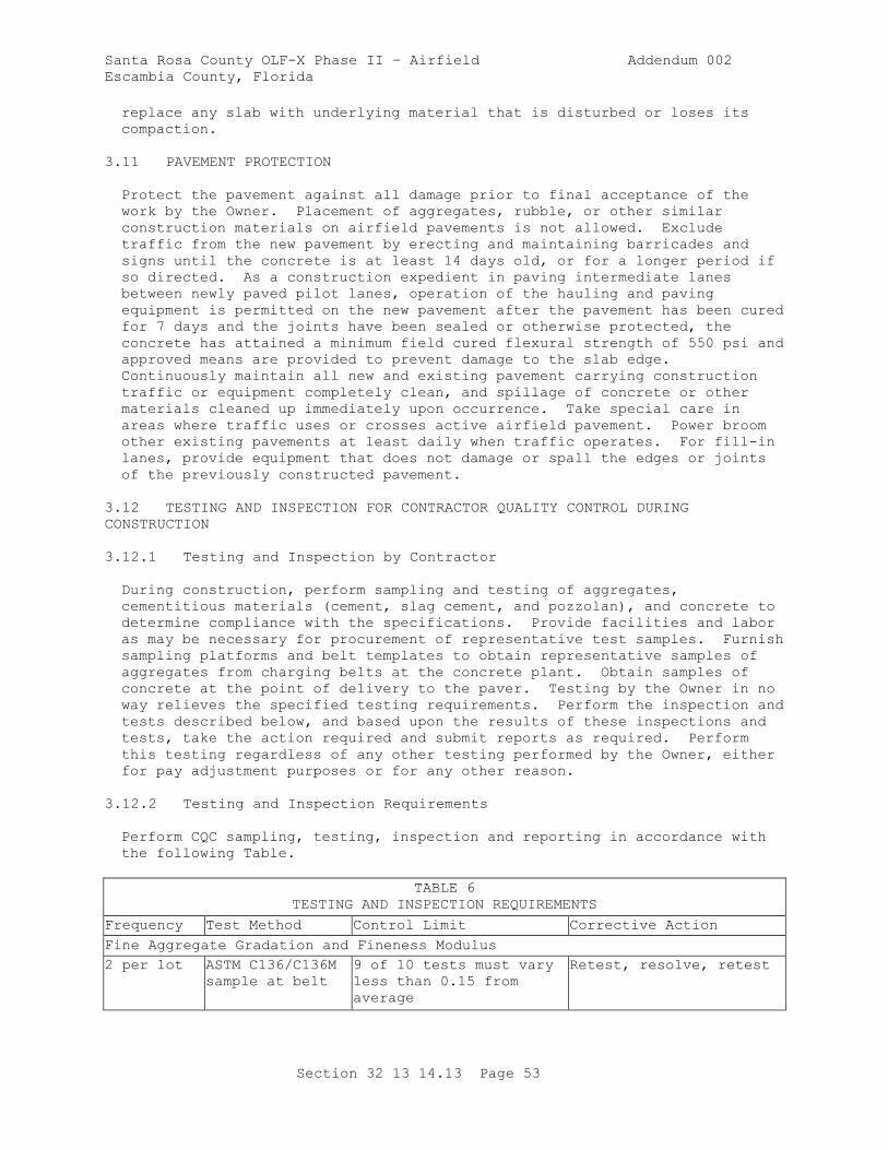
Santa Rosa County OLF-X Phase II – Airfield Addendum 002
Escambia County, Florida
Section 32 13 14.13 Page 53
replace any slab with underlying material that is disturbed or loses its
compaction.
3.11 PAVEMENT PROTECTION
Protect the pavement against all damage prior to final acceptance of the
work by the Owner. Placement of aggregates, rubble, or other similar
construction materials on airfield pavements is not allowed. Exclude
traffic from the new pavement by erecting and maintaining barricades and
signs until the concrete is at least 14 days old, or for a longer period if
so directed. As a construction expedient in paving intermediate lanes
between newly paved pilot lanes, operation of the hauling and paving
equipment is permitted on the new pavement after the pavement has been cured
for 7 days and the joints have been sealed or otherwise protected, the
concrete has attained a minimum field cured flexural strength of 550 psi and
approved means are provided to prevent damage to the slab edge.
Continuously maintain all new and existing pavement carrying construction
traffic or equipment completely clean, and spillage of concrete or other
materials cleaned up immediately upon occurrence. Take special care in
areas where traffic uses or crosses active airfield pavement. Power broom
other existing pavements at least daily when traffic operates. For fill-in
lanes, provide equipment that does not damage or spall the edges or joints
of the previously constructed pavement.
3.12 TESTING AND INSPECTION FOR CONTRACTOR QUALITY CONTROL DURING
CONSTRUCTION
3.12.1 Testing and Inspection by Contractor
During construction, perform sampling and testing of aggregates,
cementitious materials (cement, slag cement, and pozzolan), and concrete to
determine compliance with the specifications. Provide facilities and labor
as may be necessary for procurement of representative test samples. Furnish
sampling platforms and belt templates to obtain representative samples of
aggregates from charging belts at the concrete plant. Obtain samples of
concrete at the point of delivery to the paver. Testing by the Owner in no
way relieves the specified testing requirements. Perform the inspection and
tests described below, and based upon the results of these inspections and
tests, take the action required and submit reports as required. Perform
this testing regardless of any other testing performed by the Owner, either
for pay adjustment purposes or for any other reason.
3.12.2 Testing and Inspection Requirements
Perform CQC sampling, testing, inspection and reporting in accordance with
the following Table.
TABLE 6
TESTING AND INSPECTION REQUIREMENTS
Frequency Test Method Control Limit Corrective Action
Fine Aggregate Gradation and Fineness Modulus
2 per lot ASTM C136/C136M
sample at belt
9 of 10 tests must vary
less than 0.15 from
average
Retest, resolve, retest
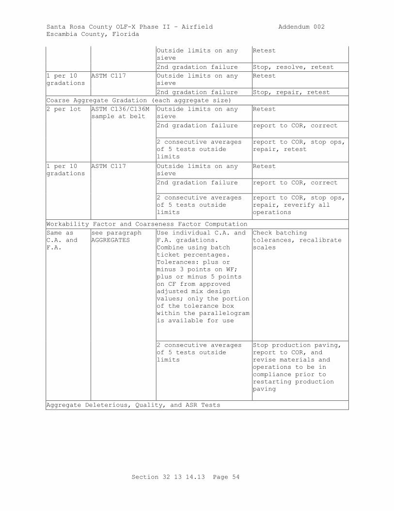
Santa Rosa County OLF-X Phase II – Airfield Addendum 002
Escambia County, Florida
Section 32 13 14.13 Page 54
Outside limits on any
sieve
Retest
2nd gradation failure Stop, resolve, retest
1 per 10
gradations
ASTM C117 Outside limits on any
sieve
Retest
2nd gradation failure Stop, repair, retest
Coarse Aggregate Gradation (each aggregate size)
2 per lot ASTM C136/C136M
sample at belt
Outside limits on any
sieve
Retest
2nd gradation failure report to COR, correct
2 consecutive averages
of 5 tests outside
limits
report to COR, stop ops,
repair, retest
1 per 10
gradations
ASTM C117 Outside limits on any
sieve
Retest
2nd gradation failure report to COR, correct
2 consecutive averages
of 5 tests outside
limits
report to COR, stop ops,
repair, reverify all
operations
Workability Factor and Coarseness Factor Computation
Same as
C.A. and
F.A.
see paragraph
AGGREGATES
Use individual C.A. and
F.A. gradations.
Combine using batch
ticket percentages.
Tolerances: plus or
minus 3 points on WF;
plus or minus 5 points
on CF from approved
adjusted mix design
values; only the portion
of the tolerance box
within the parallelogram
is available for use
Check batching
tolerances, recalibrate
scales
2 consecutive averages
of 5 tests outside
limits
Stop production paving,
report to COR, and
revise materials and
operations to be in
compliance prior to
restarting production
paving
Aggregate Deleterious, Quality, and ASR Tests
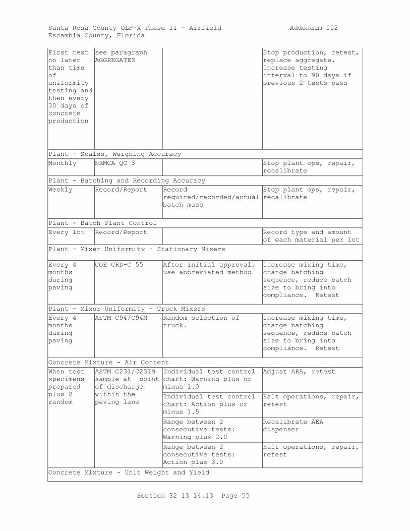
Santa Rosa County OLF-X Phase II – Airfield Addendum 002
Escambia County, Florida
Section 32 13 14.13 Page 55
First test
no later
than time
of
uniformity
testing and
then every
30 days of
concrete
production
see paragraph
AGGREGATES
Stop production, retest,
replace aggregate.
Increase testing
interval to 90 days if
previous 2 tests pass
Plant - Scales, Weighing Accuracy
Monthly NRMCA QC 3 Stop plant ops, repair,
recalibrate
Plant - Batching and Recording Accuracy
Weekly Record/Report Record
required/recorded/actual
batch mass
Stop plant ops, repair,
recalibrate
Plant - Batch Plant Control
Every lot Record/Report Record type and amount
of each material per lot
Plant - Mixer Uniformity - Stationary Mixers
Every 4
months
during
paving
COE CRD-C 55 After initial approval,
use abbreviated method
Increase mixing time,
change batching
sequence, reduce batch
size to bring into
compliance. Retest
Plant - Mixer Uniformity - Truck Mixers
Every 4
months
during
paving
ASTM C94/C94M Random selection of
truck.
Increase mixing time,
change batching
sequence, reduce batch
size to bring into
compliance. Retest
Concrete Mixture - Air Content
When test
specimens
prepared
plus 2
random
ASTM C231/C231M
sample at point
of discharge
within the
paving lane
Individual test control
chart: Warning plus or
minus 1.0
Adjust AEA, retest
Individual test control
chart: Action plus or
minus 1.5
Halt operations, repair,
retest
Range between 2
consecutive tests:
Warning plus 2.0
Recalibrate AEA
dispenser
Range between 2
consecutive tests:
Action plus 3.0
Halt operations, repair,
retest
Concrete Mixture - Unit Weight and Yield
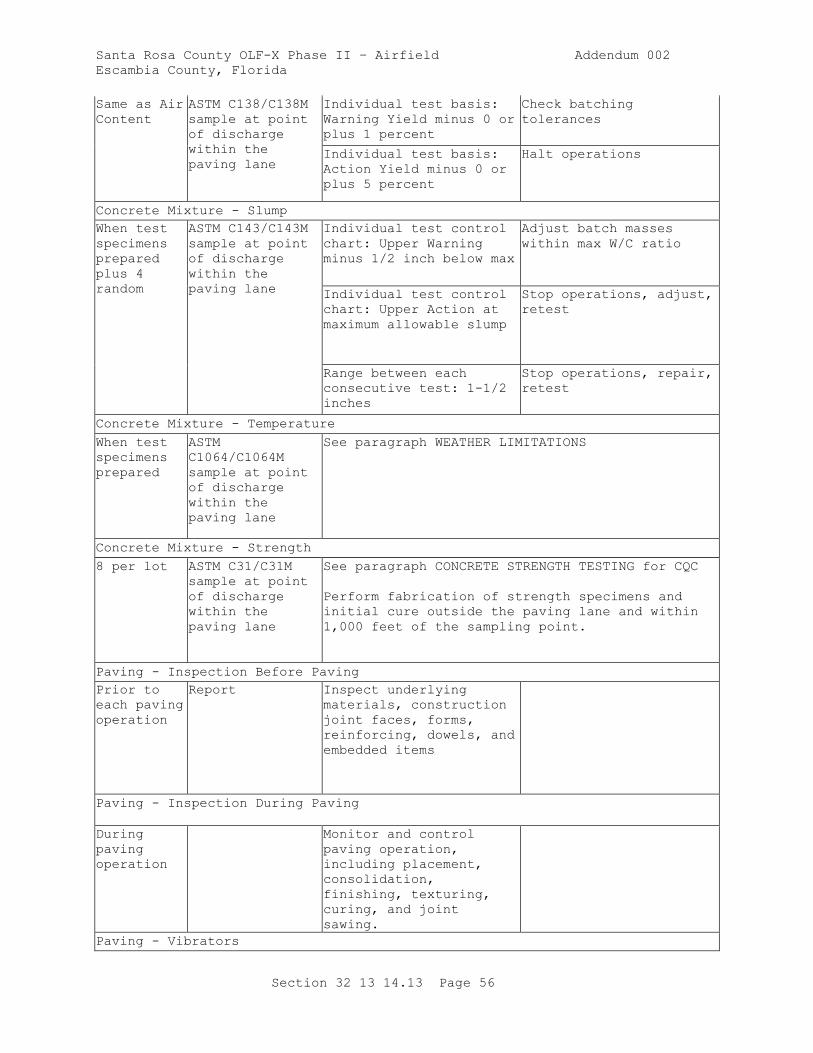
Santa Rosa County OLF-X Phase II – Airfield Addendum 002
Escambia County, Florida
Section 32 13 14.13 Page 56
Same as Air
Content
ASTM C138/C138M
sample at point
of discharge
within the
paving lane
Individual test basis:
Warning Yield minus 0 or
plus 1 percent
Check batching
tolerances
Individual test basis:
Action Yield minus 0 or
plus 5 percent
Halt operations
Concrete Mixture - Slump
When test
specimens
prepared
plus 4
random
ASTM C143/C143M
sample at point
of discharge
within the
paving lane
Individual test control
chart: Upper Warning
minus 1/2 inch below max
Adjust batch masses
within max W/C ratio
Individual test control
chart: Upper Action at
maximum allowable slump
Stop operations, adjust,
retest
Range between each
consecutive test: 1-1/2
inches
Stop operations, repair,
retest
Concrete Mixture - Temperature
When test
specimens
prepared
ASTM
C1064/C1064M
sample at point
of discharge
within the
paving lane
See paragraph WEATHER LIMITATIONS
Concrete Mixture - Strength
8 per lot ASTM C31/C31M
sample at point
of discharge
within the
paving lane
See paragraph CONCRETE STRENGTH TESTING for CQC
Perform fabrication of strength specimens and
initial cure outside the paving lane and within
1,000 feet of the sampling point.
Paving - Inspection Before Paving
Prior to
each paving
operation
Report Inspect underlying
materials, construction
joint faces, forms,
reinforcing, dowels, and
embedded items
Paving - Inspection During Paving
During
paving
operation
Monitor and control
paving operation,
including placement,
consolidation,
finishing, texturing,
curing, and joint
sawing.
Paving - Vibrators
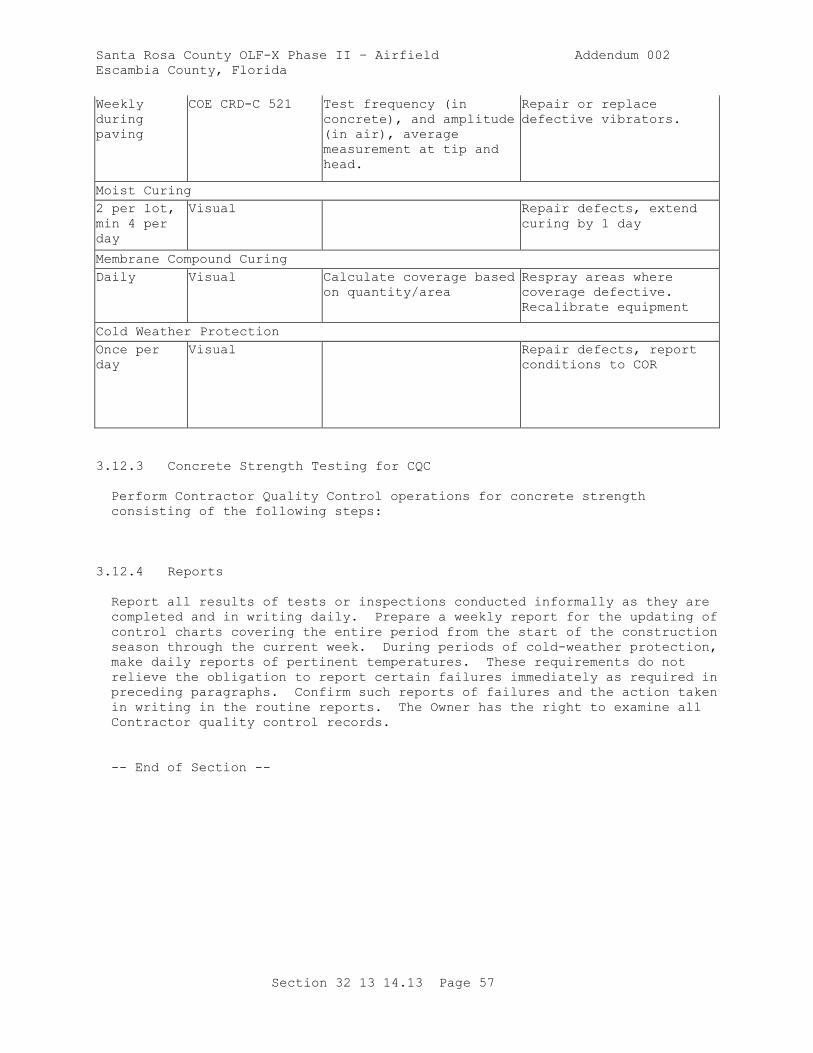
Santa Rosa County OLF-X Phase II – Airfield Addendum 002
Escambia County, Florida
Section 32 13 14.13 Page 57
Weekly
during
paving
COE CRD-C 521 Test frequency (in
concrete), and amplitude
(in air), average
measurement at tip and
head.
Repair or replace
defective vibrators.
Moist Curing
2 per lot,
min 4 per
day
Visual Repair defects, extend
curing by 1 day
Membrane Compound Curing
Daily Visual Calculate coverage based
on quantity/area
Respray areas where
coverage defective.
Recalibrate equipment
Cold Weather Protection
Once per
day
Visual Repair defects, report
conditions to COR
3.12.3 Concrete Strength Testing for CQC
Perform Contractor Quality Control operations for concrete strength
consisting of the following steps:
3.12.4 Reports
Report all results of tests or inspections conducted informally as they are
completed and in writing daily. Prepare a weekly report for the updating of
control charts covering the entire period from the start of the construction
season through the current week. During periods of cold-weather protection,
make daily reports of pertinent temperatures. These requirements do not
relieve the obligation to report certain failures immediately as required in
preceding paragraphs. Confirm such reports of failures and the action taken
in writing in the routine reports. The Owner has the right to examine all
Contractor quality control records.
-- End of Section --
Santa Rosa County OLF-X Phase II – Airfield Addendum 002
Escambia County, Florida
Section 32 16 13 Page 1
SECTION 32 16 13
CONCRETE SIDEWALKS AND CURBS AND GUTTERS
PART 1 GENERAL
1.1 MEASUREMENT FOR PAYMENT
1.1.1 Sidewalks
The quantities of sidewalks to be paid for will be the number of square
yards of each depth of sidewalk constructed as indicated.
1.1.2 Curbs and Gutters
The quantities of curbs and gutters to be paid for will be the number of
linearfeet of each cross section constructed as indicated, measured along
the face of the curb at the gutter line.
1.2 BASIS FOR PAYMENT
1.2.1 Sidewalks
Payment of the quantities of sidewalks measured as specified will be at the
Contract unit price per linear foot of the thickness and width specified.
1.2.2 Curbs and Gutters
Payment of the quantities of curbs and gutters measured as specified will be
at the Contract unit price per linear foot of each cross section.
1.3 REFERENCES
The publications listed below form a part of this specification to the
extent referenced. The publications are referred to within the text by the
basic designation only.
AMERICAN ASSOCIATION OF STATE HIGHWAY AND TRANSPORTATION OFFICIALS
(AASHTO)
AASHTO M 182 (2005; R 2017) Standard Specification for
Burlap Cloth Made from Jute or Kenaf and
Cotton Mats
ASTM INTERNATIONAL (ASTM)
ASTM A1064/A1064M (2017) Standard Specification for Carbon-
Steel Wire and Welded Wire Reinforcement,
Plain and Deformed, for Concrete
ASTM A615/A615M (2016) Standard Specification for Deformed
and Plain Carbon-Steel Bars for Concrete
Reinforcement
Santa Rosa County OLF-X Phase II – Airfield Addendum 002
Escambia County, Florida
Section 32 16 13 Page 2
ASTM C143/C143M (2015) Standard Test Method for Slump of
Hydraulic-Cement Concrete
ASTM C171 (2016) Standard Specification for Sheet
Materials for Curing Concrete
ASTM C172/C172M (2014a) Standard Practice for Sampling
Freshly Mixed Concrete
ASTM C173/C173M (2016) Standard Test Method for Air Content
of Freshly Mixed Concrete by the Volumetric
Method
ASTM C231/C231M (2017a) Standard Test Method for Air Content
of Freshly Mixed Concrete by the Pressure
Method
ASTM C309 (2011) Standard Specification for Liquid
Membrane-Forming Compounds for Curing
Concrete
ASTM C31/C31M (2017) Standard Practice for Making and
Curing Concrete Test Specimens in the Field
ASTM C920 (2014a) Standard Specification for
Elastomeric Joint Sealants
ASTM D1751 (2004; E 2013; R 2013) Standard Specification
for Preformed Expansion Joint Filler for
Concrete Paving and Structural Construction
(Nonextruding and Resilient Bituminous Types)
ASTM D1752 (2004a; R 2013) Standard Specification for
Preformed Sponge Rubber Cork and Recycled PVC
Expansion
ASTM D5893/D5893M (2016) Standard Specification for Cold
Applied, Single Component, Chemically Curing
Silicone Joint Sealant for Portland Cement
Concrete Pavements
INTERNATIONAL CODE COUNCIL (ICC)
ICC A117.1 COMM (2017) Standard And Commentary Accessible and
Usable Buildings and Facilities
1.4 SYSTEM DESCRIPTION
1.4.1 General Requirements
Provide plant, equipment, machines, and tools used in the work subject to
approval and maintained in a satisfactory working condition at all times.
The equipment must have the capability of producing the required product,
meeting grade controls, thickness control and smoothness requirements as
specified. Use of the equipment must be discontinued if it produces
unsatisfactory results. The Contracting Officer must have access at all
Santa Rosa County OLF-X Phase II – Airfield Addendum 002
Escambia County, Florida
Section 32 16 13 Page 3
times to the plant and equipment to ensure proper operation and compliance
with specifications.
1.4.2 Slip Form Equipment
Slip form paver or curb forming machine, will be approved based on trial use
on the job and must be self-propelled, automatically controlled, crawler
mounted, and capable of spreading, consolidating, and shaping the plastic
concrete to the desired cross section in 1 pass.
1.5 SUBMITTALS
Owner approval is required for submittals with a "G" designation; submittals
not having a "G" designation are for information only. Submit the following
in accordance with Section 01 33 00 SUBMITTAL PROCEDURES:
SD-03 Product Data
Concrete
Biodegradable Form Release Agent
SD-06 Test Reports
Field Quality Control
1.6 ENVIRONMENTAL REQUIREMENTS
1.6.1 Placing During Cold Weather
Do not place concrete when the air temperature reaches 40 degrees F and is
falling, or is already below that point. Placement may begin when the air
temperature reaches 35 degrees F and is rising, or is already above 40
degrees F. Make provisions to protect the concrete from freezing during the
specified curing period. If necessary to place concrete when the
temperature of the air, aggregates, or water is below 35 degrees F,
placement and protection must be approved in writing. Approval will be
contingent upon full conformance with the following provisions. The
underlying material must be prepared and protected so that it is entirely
free of frost when the concrete is deposited. Mixing water must be heated
as necessary to result in the temperature of the in-place concrete being
between 50 and 85 degrees F. Methods and equipment for heating must be
approved. The aggregates must be free of ice, snow, and frozen lumps before
entering the mixer. Covering and other means must be provided for
maintaining the concrete at a temperature of at least 50 degrees F for not
less than 72 hours after placing, and at a temperature above freezing for
the remainder of the curing period.
1.6.2 Placing During Warm Weather
The temperature of the concrete as placed must not exceed85 degrees F except
where an approved retarder is used. The mixing water and aggregates must be
cooled, if necessary, to maintain a satisfactory placing temperature. The
placing temperature must not exceed95 degrees F at any time.
PART 2 PRODUCTS
Santa Rosa County OLF-X Phase II – Airfield Addendum 002
Escambia County, Florida
Section 32 16 13 Page 4
2.1 CONCRETE
Provide concrete conforming to the applicable requirements of Section 32 13
14.13 CONCRETE PAVING FOR AIRFIELDS AND OTHER HEAVY DUTY PAVEMENTS except as
otherwise specified. Concrete must have a minimum compressive strength of
3500 psi at 28 days. Size of aggregate must not exceed 1-1/2 inches.
Submit copies of certified delivery tickets for all concrete used in the
construction.
2.1.1 Air Content
Mixtures must have air content by volume of concrete of 5 to 7 percent,
based on measurements made immediately after discharge from the mixer.
2.1.2 Slump
The concrete slump must be 2 inches plus or minus 1 inch where determined in
accordance with ASTM C143/C143M.
2.1.3 Reinforcement Steel
Reinforcement bars must conform to ASTM A615/A615M. Wire mesh reinforcement
must conform to ASTM A1064/A1064M.
2.2 CONCRETE CURING MATERIALS
2.2.1 Impervious Sheet Materials
Impervious sheet materials must conform to ASTM C171, type optional, except
that polyethylene film, if used, must be white opaque.
2.2.2 Burlap
Burlap must conform to AASHTO M 182.
2.2.3 White Pigmented Membrane-Forming Curing Compound
White pigmented membrane-forming curing compound must conform to ASTM C309,
Type 2.
2.3 CONCRETE PROTECTION MATERIALS
Concrete protection materials must be a linseed oil mixture of equal parts,
by volume, of linseed oil and either mineral spirits, naphtha, or
turpentine. At the option of the Contractor, commercially prepared linseed
oil mixtures, formulated specifically for application to concrete to provide
protection against the action of deicing chemicals may be used, except that
emulsified mixtures are not acceptable.
2.4 JOINT FILLER STRIPS
2.4.1 Contraction Joint Filler for Curb and Gutter
Contraction joint filler for curb and gutter must consist of hard-pressed
fiberboard.
Santa Rosa County OLF-X Phase II – Airfield Addendum 002
Escambia County, Florida
Section 32 16 13 Page 5
2.4.2 Expansion Joint Filler, Premolded
Expansion joint filler, premolded, must conform to ASTM D1751 or ASTM D1752,
1/2 inch thick, unless otherwise indicated.
2.5 JOINT SEALANTS
Joint sealant, cold-applied must conform to ASTM C920 or ASTM D5893/D5893M.
2.6 FORM WORK
Design and construct form work to ensure that the finished concrete will
conform accurately to the indicated dimensions, lines, and elevations, and
within the tolerances specified. Forms must be of wood or steel, straight,
of sufficient strength to resist springing during depositing and
consolidating concrete. Wood forms must be surfaced plank, 2 inches
nominal thickness, straight and free from warp, twist, loose knots, splits
or other defects. Wood forms must have a nominal length of 10 feet. Radius
bends may be formed with 3/4 inch boards, laminated to the required
thickness. Steel forms must be channel-formed sections with a flat top
surface and with welded braces at each end and at not less than two
intermediate points. Ends of steel forms must be interlocking and self-
aligning. Steel forms must include flexible forms for radius forming,
corner forms, form spreaders, and fillers. Steel forms must have a nominal
length of 10 feet with a minimum of 3 welded stake pockets per form. Stake
pins must be solid steel rods with chamfered heads and pointed tips designed
for use with steel forms.
2.6.1 Sidewalk Forms
Sidewalk forms must be of a height equal to the full depth of the finished
sidewalk.
2.6.2 Curb and Gutter Forms
Curb and gutter outside forms must have a height equal to the full depth of
the curb or gutter. The inside form of curb must have batter as indicated
and must be securely fastened to and supported by the outside form. Rigid
forms must be provided for curb returns, except that benders or thin plank
forms may be used for curb or curb returns with a radius of 10 feet or more,
where grade changes occur in the return, or where the central angle is such
that a rigid form with a central angle of 90 degrees cannot be used. Back
forms for curb returns may be made of 1-1/2 inch benders, for the full height
of the curb, cleated together. In lieu of inside forms for curbs, a curb
"mule" may be used for forming and finishing this surface, provided the
results are approved.
2.7 DETECTABLE WARNING SYSTEM
Detectable Warning Systems shown on the Contract plans are to meet
requirements of ICC A117.1 COMM - Section 705.
PART 3 EXECUTION
3.1 SUBGRADE PREPARATION
Santa Rosa County OLF-X Phase II – Airfield Addendum 002
Escambia County, Florida
Section 32 16 13 Page 6
The subgrade must be constructed to the specified grade and cross section
prior to concrete placement. Subgrade must be placed and compacted as
directed.
3.1.1 Sidewalk Subgrade
The subgrade must be tested for grade and cross section with a template
extending the full width of the sidewalk and supported between side forms.
3.1.2 Curb and Gutter Subgrade
The subgrade must be tested for grade and cross section by means of a
template extending the full width of the curb and gutter. The subgrade must
be of materials equal in bearing quality to the subgrade under the adjacent
pavement.
3.1.3 Maintenance of Subgrade
The subgrade must be maintained in a smooth, compacted condition in
conformity with the required section and established grade until the
concrete is placed. The subgrade must be in a moist condition when concrete
is placed. The subgrade must be prepared and protected to produce a
subgrade free from frost when the concrete is deposited.
3.2 FORM SETTING
Set forms to the indicated alignment, grade and dimensions. Hold forms
rigidly in place by a minimum of 3 stakes per form placed at intervals not
to exceed 4 feet. Corners, deep sections, and radius bends must have
additional stakes and braces, as required. Clamps, spreaders, and braces
must be used where required to ensure rigidity in the forms. Forms must be
removed without injuring the concrete. Bars or heavy tools must not be used
against the concrete in removing the forms. Concrete found defective after
form removal must be promptly and satisfactorily repaired. Forms must be
cleaned and coated with form oil or biodegradable form release agent each
time before concrete is placed. Wood forms may, instead, be thoroughly
wetted with water before concrete is placed, except that with probable
freezing temperatures, oiling is mandatory.
3.2.1 Sidewalks
Set forms for sidewalks with the upper edge true to line and grade with an
allowable tolerance of 1/8 inch in any 10 foot long section. After forms
are set, grade and alignment must be checked with a 10 foot straightedge.
Forms must have a transverse slope as indicated with the low side adjacent
to the roadway. Side forms must not be removed for 12 hours after finishing
has been completed.
3.2.2 Curbs and Gutters
The forms of the front of the curb must be removed not less than 2 hours nor
more than 6 hours after the concrete has been placed. Forms back of curb
must remain in place until the face and top of the curb have been finished,
as specified for concrete finishing. Gutter forms must not be removed while
the concrete is sufficiently plastic to slump in any direction.
Santa Rosa County OLF-X Phase II – Airfield Addendum 002
Escambia County, Florida
Section 32 16 13 Page 7
3.3 SIDEWALK CONCRETE PLACEMENT AND FINISHING
3.3.1 Formed Sidewalks
Place concrete in the forms in one layer. When consolidated and finished,
the sidewalks must be of the thickness indicated. After concrete has been
placed in the forms, a strike-off guided by side forms must be used to bring
the surface to proper section to be compacted. The concrete must be
consolidated by tamping and spading or with an approved vibrator, and the
surface must be finished to grade with a strike off.
3.3.2 Concrete Finishing
After straightedging, when most of the water sheen has disappeared, and just
before the concrete hardens, finish the surface with a wood or magnesium
float or darby to a smooth and uniformly fine granular or sandy texture free
of waves, irregularities, or tool marks. A scored surface must be produced
by brooming with a fiber-bristle brush in a direction transverse to that of
the traffic, followed by edging.
3.3.3 Edge and Joint Finishing
All slab edges, including those at formed joints, must be finished with an
edger having a radius of 1/8 inch. Transverse joint must be edged before
brooming, and the brooming must eliminate the flat surface left by the
surface face of the edger. Corners and edges which have crumbled and areas
which lack sufficient mortar for proper finishing must be cleaned and filled
solidly with a properly proportioned mortar mixture and then finished.
3.3.4 Surface and Thickness Tolerances
Finished surfaces must not vary more than 5/16 inch from the testing edge of
a 10-foot straightedge. Permissible deficiency in section thickness will be
up to 1/4 inch.
3.4 CURB AND GUTTER CONCRETE PLACEMENT AND FINISHING
3.4.1 Formed Curb and Gutter
Concrete must be placed to the section required in a single lift.
Consolidation must be achieved by using approved mechanical vibrators.
Curve shaped gutters must be finished with a standard curb "mule".
3.4.2 Curb and Gutter Finishing
Approved slipformed curb and gutter machines may be used in lieu of hand
placement.
3.4.3 Concrete Finishing
Exposed surfaces must be floated and finished with a smooth wood float until
true to grade and section and uniform in texture. Floated surfaces must
then be brushed with a fine-hair brush with longitudinal strokes. The edges
of the gutter and top of the curb must be rounded with an edging tool to a
radius of 1/2 inch. Immediately after removing the front curb form, the
face of the curb must be rubbed with a wood or concrete rubbing block and
water until blemishes, form marks, and tool marks have been removed. The

Santa Rosa County OLF-X Phase II – Airfield Addendum 002
Escambia County, Florida
Section 32 16 13 Page 8
front curb surface, while still wet, must be brushed in the same manner as
the gutter and curb top. The top surface of gutter and entrance must be
finished to grade with a wood float.
3.4.4 Joint Finishing
Curb edges at formed joints must be finished as indicated.
3.4.5 Surface and Thickness Tolerances
Finished surfaces must not vary more than 1/4 inch from the testing edge of
a 10-foot straightedge. Permissible deficiency in section thickness will be
up to 1/4 inch.
3.5 SIDEWALK JOINTS
Sidewalk joints must be constructed to divide the surface into rectangular
areas. Transverse contraction joints must be spaced at a distance equal to
the sidewalk width or 5 feet on centers, whichever is less, and must be
continuous across the slab. Longitudinal contraction joints must be
constructed along the centerline of all sidewalks 10 feet or more in width.
Transverse expansion joints must be installed at sidewalk returns and
opposite expansion joints in adjoining curbs. Where the sidewalk is not in
contact with the curb, transverse expansion joints must be installed as
indicated. Expansion joints must be formed about structures and features
which project through or into the sidewalk pavement, using joint filler of
the type, thickness, and width indicated. Expansion joints are not required
between sidewalks and curb that abut the sidewalk longitudinally.
3.5.1 Sidewalk Contraction Joints
The contraction joints must be formed in the fresh concrete by cutting a
groove in the top portion of the slab to a depth of at least one-fourth of
the sidewalk slab thickness, using a jointer to cut the groove, or by sawing
a groove in the hardened concrete with a power-driven saw, unless otherwise
approved. Sawed joints must be constructed by sawing a groove in the
concrete with a 1/8 inch blade to the depth indicated. An ample supply of
saw blades must be available on the job before concrete placement is
started, and at least one standby sawing unit in good working order must be
available at the jobsite at all times during the sawing operations.
3.5.2 Sidewalk Expansion Joints
Expansion joints must be formed with 1/2 inch joint filler strips. Joint
filler in expansion joints surrounding structures and features within the
sidewalk may consist of preformed filler material conforming to ASTM D1752
or building paper. Joint filler must be held in place with steel pins or
other devices to prevent warping of the filler during floating and
finishing. Immediately after finishing operations are completed, joint
edges must be rounded with an edging tool having a radius of 1/8 inch, and
concrete over the joint filler must be removed. At the end of the curing
period, expansion joints must be cleaned and filled with cold-applied joint
sealant. Joint sealant must be gray or stone in color. The joint opening
must be thoroughly cleaned before the sealing material is placed. Sealing
material must not be spilled on exposed surfaces of the concrete. Concrete
at the joint must be surface dry and atmospheric and concrete temperatures
must be above 50 degrees F at the time of application of joint sealing
Santa Rosa County OLF-X Phase II – Airfield Addendum 002
Escambia County, Florida
Section 32 16 13 Page 9
material. Excess material on exposed surfaces of the concrete must be
removed immediately and concrete surfaces cleaned.
3.5.3 Reinforcement Steel Placement
Reinforcement steel must be accurately and securely fastened in place with
suitable supports and ties before the concrete is placed.
3.6 CURB AND GUTTER JOINTS
Curb and gutter joints must be constructed at right angles to the line of
curb and gutter.
3.6.1 Contraction Joints
Contraction joints must be constructed directly opposite contraction joints
in abutting portland cement concrete pavements and spaced so that monolithic
sections between curb returns will not be less than 5 feet nor greater than
15 feet in length.
a. Contraction joints (except for slip forming) must be constructed by
means of 1/8 inch thick separators and of a section conforming to the
cross section of the curb and gutter. Separators must be removed as
soon as practicable after concrete has set sufficiently to preserve the
width and shape of the joint and prior to finishing.
b. When slip forming is used, the contraction joints must be cut in the
top portion of the gutter/curb hardened concrete in a continuous cut
across the curb and gutter, using a power-driven saw. The depth of cut
must be at least one-fourth of the gutter/curb depth and 1/8 inch in
width.
3.6.2 Expansion Joints
Expansion joints must be formed by means of preformed expansion joint filler
material cut and shaped to the cross section of curb and gutter. Expansion
joints must be provided in curb and gutter directly opposite expansion
joints of abutting portland cement concrete pavement, and must be of the
same type and thickness as joints in the pavement. Where curb and gutter do
not abut portland cement concrete pavement, expansion joints at least 1/2
inch in width must be provided at intervals not less than 30 feet nor
greater than 120 feet. Expansion joints must be provided in nonreinforced
concrete gutter at locations indicated. Expansion joints must be sealed
immediately following curing of the concrete or as soon thereafter as
weather conditions permit. Expansion joints and the top 1 inch depth of
curb and gutter contraction-joints must be sealed with joint sealant. The
joint opening must be thoroughly cleaned before the sealing material is
placed. Sealing material must not be spilled on exposed surfaces of the
concrete. Concrete at the joint must be surface dry and atmospheric and
concrete temperatures must be above 50 degrees F at the time of application
of joint sealing material. Excess material on exposed surfaces of the
concrete must be removed immediately and concrete surfaces cleaned.
3.7 CURING AND PROTECTION
3.7.1 General Requirements
Santa Rosa County OLF-X Phase II – Airfield Addendum 002
Escambia County, Florida
Section 32 16 13 Page 10
Protect concrete against loss of moisture and rapid temperature changes for
at least 7 days from the beginning of the curing operation. Protect
unhardened concrete from rain and flowing water. All equipment needed for
adequate curing and protection of the concrete must be on hand and ready for
use before actual concrete placement begins. Protection must be provided as
necessary to prevent cracking of the pavement due to temperature changes
during the curing period.
3.7.1.1 Mat Method
The entire exposed surface must be covered with 2 or more layers of burlap.
Mats must overlap each other at least 6 inches. The mat must be thoroughly
wetted with water prior to placing on concrete surface and must be kept
continuously in a saturated condition and in intimate contact with concrete
for not less than 7 days.
3.7.1.2 Impervious Sheeting Method
The entire exposed surface must be wetted with a fine spray of water and
then covered with impervious sheeting material. Sheets must be laid
directly on the concrete surface with the light-colored side up and
overlapped 12 inches when a continuous sheet is not used. The curing medium
must not be less than 18-inches wider than the concrete surface to be cured,
and must be securely weighted down by heavy wood planks, or a bank of moist
earth placed along edges and laps in the sheets. Sheets must be
satisfactorily repaired or replaced if torn or otherwise damaged during
curing. The curing medium must remain on the concrete surface to be cured
for not less than 7 days.
3.7.1.3 Membrane Curing Method
A uniform coating of white-pigmented membrane-curing compound must be
applied to the entire exposed surface of the concrete as soon after
finishing as the free water has disappeared from the finished surface.
Formed surfaces must be coated immediately after the forms are removed and
in no case longer than 1 hour after the removal of forms. Concrete must not
be allowed to dry before the application of the membrane. If drying has
occurred, the surface of the concrete must be moistened with a fine spray of
water and the curing compound applied as soon as the free water disappears.
Curing compound must be applied in two coats by hand-operated pressure
sprayers at a coverage of approximately 200 square feet/gallon for the total
of both coats. The second coat must be applied in a direction approximately
at right angles to the direction of application of the first coat. The
compound must form a uniform, continuous, coherent film that will not check,
crack, or peel and must be free from pinholes or other imperfections. If
pinholes, abrasion, or other discontinuities exist, an additional coat must
be applied to the affected areas within 30 minutes. Concrete surfaces that
are subjected to heavy rainfall within 3 hours after the curing compound has
been applied must be resprayed by the method and at the coverage specified
above. Areas where the curing compound is damaged by subsequent
construction operations within the curing period must be resprayed.
Necessary precautions must be taken to ensure that the concrete is properly
cured at sawed joints, and that no curing compound enters the joints. The
top of the joint opening and the joint groove at exposed edges must be
tightly sealed before the concrete in the region of the joint is resprayed
with curing compound. The method used for sealing the joint groove must
prevent loss of moisture from the joint during the entire specified curing
Santa Rosa County OLF-X Phase II – Airfield Addendum 002
Escambia County, Florida
Section 32 16 13 Page 11
period. Approved standby facilities for curing concrete pavement must be
provided at a location accessible to the jobsite for use in the event of
mechanical failure of the spraying equipment or other conditions that might
prevent correct application of the membrane-curing compound at the proper
time. Concrete surfaces to which membrane-curing compounds have been
applied must be adequately protected during the entire curing period from
pedestrian and vehicular traffic, except as required for joint-sawing
operations and surface tests, and from other possible damage to the
continuity of the membrane.
3.7.2 Backfilling
After curing, debris must be removed and the area adjoining the concrete
must be backfilled, graded, and compacted to conform to the surrounding area
in accordance with lines and grades indicated.
3.7.3 Protection
Completed concrete must be protected from damage until accepted. Repair
damaged concrete and clean concrete discolored during construction.
Concrete that is damaged must be removed and reconstructed for the entire
length between regularly scheduled joints. Refinishing the damaged portion
will not be acceptable. Removed damaged portions must be disposed of as
directed.
3.7.4 Protective Coating
Protective coating, of linseed oil mixture, must be applied to the exposed-
to-view concrete surface after the curing period, if concrete will be
exposed to de-icing chemicals within 6 weeks after placement. Concrete to
receive a protective coating must be moist cured.
3.7.4.1 Application
Curing and backfilling operation must be completed prior to applying two
coats of protective coating. Concrete must be surface dry and clean before
each application. Coverage must be by spray application at not more than 50
square yards/gallon for first application and not more than 70 square
yards/gallon for second application, except that the number of applications
and coverage for each application for commercially prepared mixture must be
in accordance with the manufacturer's instructions. Coated surfaces must be
protected from vehicular and pedestrian traffic until dry.
3.7.4.2 Precautions
Protective coating must not be heated by direct application of flame or
electrical heaters and must be protected from exposure to open flame,
sparks, and fire adjacent to open containers or applicators. Material must
not be applied at ambient or material temperatures lower than 50 degrees F.
3.8 FIELD QUALITY CONTROL
Submit copies of all test reports within 24 hours of completion of the test.
3.8.1 General Requirements
Santa Rosa County OLF-X Phase II – Airfield Addendum 002
Escambia County, Florida
Section 32 16 13 Page 12
Perform the inspection and tests described and meet the specified
requirements for inspection details and frequency of testing. Based upon
the results of these inspections and tests, take the action and submit
reports as required below, and additional tests to ensure that the
requirements of these specifications are met.
3.8.2 Concrete Testing
3.8.2.1 Strength Testing
Provide molded concrete specimens for strength tests. Samples of concrete
placed each day must be taken not less than once a day nor less than once
for every 250 cubic yards of concrete. The samples for strength tests must
be taken in accordance with ASTM C172/C172M. Cylinders for acceptance must
be molded in conformance with ASTM C31/C31M by an approved testing
laboratory. Each strength test result must be the average of 2 test
cylinders from the same concrete sample tested at 28 days, unless otherwise
specified or approved. Concrete specified on the basis of compressive
strength will be considered satisfactory if the averages of all sets of
three consecutive strength test results equal or exceed the specified
strength, and no individual strength test result falls below the specified
strength by more than 500 psi.
3.8.2.2 Air Content
Determine air content in accordance with ASTM C173/C173M or ASTM C231/C231M.
ASTM C231/C231M must be used with concretes and mortars made with relatively
dense natural aggregates. Two tests for air content must be made on
randomly selected batches of each class of concrete placed during each
shift. Additional tests must be made when excessive variation in concrete
workability is reported by the placing foreman or the Owner's
Representative. If results are out of tolerance, the placing foreman must
be notified and he must take appropriate action to have the air content
corrected at the plant. Additional tests for air content will be performed
on each truckload of material until such time as the air content is within
the tolerance specified.
3.8.2.3 Slump Test
Two slump tests must be made on randomly selected batches of each class of
concrete for every 250 cubic yards, or fraction thereof, of concrete placed
during each shift. Additional tests must be performed when excessive
variation in the workability of the concrete is noted or when excessive
crumbling or slumping is noted along the edges of slip-formed concrete.
3.8.3 Thickness Evaluation
The anticipated thickness of the concrete must be determined prior to
placement by passing a template through the formed section or by measuring
the depth of opening of the extrusion template of the curb forming machine.
If a slip form paver is used for sidewalk placement, the subgrade must be
true to grade prior to concrete placement and the thickness will be
determined by measuring each edge of the completed slab.
3.8.4 Surface Evaluation
Santa Rosa County OLF-X Phase II – Airfield Addendum 002
Escambia County, Florida
Section 32 16 13 Page 13
The finished surface of each category of the completed work must be uniform
in color and free of blemishes and form or tool marks.
3.9 SURFACE DEFICIENCIES AND CORRECTIONS
3.9.1 Thickness Deficiency
When measurements indicate that the completed concrete section is deficient
in thickness by more than 1/4 inch the deficient section will be removed,
between regularly scheduled joints, and replaced.
3.9.2 High Areas
In areas not meeting surface smoothness and plan grade requirements, high
areas must be reduced either by rubbing the freshly finished concrete with
carborundum brick and water when the concrete is less than 36 hours old or
by grinding the hardened concrete with an approved surface grinding machine
after the concrete is 36 hours old or more. The area corrected by grinding
the surface of the hardened concrete must not exceed 5 percent of the area
of any integral slab, and the depth of grinding must not exceed 1/4 inch.
Pavement areas requiring grade or surface smoothness corrections in excess
of the limits specified above must be removed and replaced.
3.9.3 Appearance
Exposed surfaces of the finished work will be inspected by the Contracting
Officer and deficiencies in appearance will be identified. Areas which
exhibit excessive cracking, discoloration, form marks, or tool marks or
which are otherwise inconsistent with the overall appearances of the work
must be removed and replaced.
-- End of Section --
Santa Rosa County OLF-X Phase II – Airfield Addendum 002
Escambia County, Florida
Section 32 17 23 Page 1
SECTION 32 17 23
PAVEMENT MARKINGS
PART 1 GENERAL
1.1 UNIT PRICES
1.1.1 Payment
The quantities of surface preparation, pavement striping or markings, raised
pavement markers, and removal of pavement markings determined as specified
in paragraph Measurement, will be paid for at the contract unit price. The
payment constitutes full compensation for furnishing all labor, materials,
tools, equipment, appliances, and doing all work involved in preparing and
marking the pavements as shown on the drawings. Remove and replace any
striping or markings which required reflective media, but are placed without
it, do not meet the stated minimum retro-reflective requirements, or with
other defects, at no cost to the Owner. Remove and replace striping or
markings which do not conform to the required physical characteristics,
alignment or location required at no cost to the Owner.
1.2 REFERENCES
The publications listed below form a part of this specification to the
extent referenced. The publications are referred to in the text by the
basic designation only.
AMERICAN ASSOCIATION OF STATE HIGHWAY AND TRANSPORTATION OFFICIALS
(AASHTO)
AASHTO M 247 (2013) Standard Specification for Glass Beads
Used in Pavement Markings
ASTM INTERNATIONAL (ASTM)
ASTM D4061 (2013) Standard Test Method for
Retroreflectance of Horizontal Coatings
ASTM D6628 (2003; R 2015) Standard Specification for
Color of Pavement Marking Materials
ASTM E1710 (2011) Standard Test Method for Measurement
of Retroreflective Pavement Marking Materials
with CEN-Prescribed Geometry Using a Portable
Retroreflectometer
ASTM E2177 (2011) Standard Test Method for Measuring the
Coefficient of Retroreflected Luminance (RL)
of Pavement Markings in a Standard Condition
of Wetness
ASTM E2302 (2003; R 2016) Standard Test Method for
Measurement of the Luminance Coefficient
Under Diffuse Illumination of Pavement
Santa Rosa County OLF-X Phase II – Airfield Addendum 002
Escambia County, Florida
Section 32 17 23 Page 2
Marking Materials Using a Portable
Reflectometer
INTERNATIONAL CONCRETE REPAIR INSTITUTE (ICRI)
ICRI 03732 (1997) Selecting and Specifying Concrete
Surface Preparation for Sealers, Coatings,
and Polymer Overlays
MASTER PAINTERS INSTITUTE (MPI)
MPI 97 (2015) Traffic Marking Paint, Latex
U.S. FEDERAL HIGHWAY ADMINISTRATION (FHWA)
MUTCD (2009) Manual on Uniform Traffic Control
Devices
U.S. GENERAL SERVICES ADMINISTRATION (GSA)
FED-STD-595 (Rev C; Notice 1) Colors Used in Government
Procurement
FS TT-B-1325 (Rev D; Notice 1; Notice 2 2017) Beads (Glass
Spheres) Retro-Reflective (Metric)
1.3 SUBMITTALS
Owner approval is required for submittals with a "G" designation; submittals
not having a "G" designation are for information only or as otherwise
designated. When used, a designation following the "G" designation
identifies the office that will review the submittal for the Owner. Submit
the following in accordance with Section 01 33 00 SUBMITTAL PROCEDURES:
SD-03 Product Data
Surface Preparation Equipment List; G
Application Equipment List; G
Exterior Surface Preparation
Safety Data Sheets; G
Reflective media for airfields; G
Reflective media for roads; G
Waterborne Paint; G
Solventborne Paint; G
Thermoplastic compound; G
Raised Pavement Markers Primers and Adhesives; G
SD-06 Test Reports
Santa Rosa County OLF-X Phase II – Airfield Addendum 002
Escambia County, Florida
Section 32 17 23 Page 3
Reflective Media for Airfields; G
Reflective Media for Roads; G
Waterborne Paint; G
Solventborne Paint; G
High Build Acrylic Coating (HBAC); G
Thermoplastic Compound; G
Raised Pavement Markers Primers and Adhesives; G
Test Reports
SD-07 Certificates
Qualifications; G
Reflective Media for Airfields
Reflective Media for Roads
Waterborne Paint
Solventborne Paint
Volatile Organic Compound, (VOC); G
Thermoplastic Compound
SD-08 Manufacturer's Instructions
Waterborne Paint; G
Solventborne Paint; G
Thermoplastic Compound; G
1.4 QUALITY ASSURANCE
1.4.1 Regulatory Requirements
Submit certificate stating that the proposed pavement marking paint meets
the Volatile Organic Compound, (VOC) regulations of the local Air Pollution
Control District having jurisdiction over the geographical area in which the
project is located. Submit Safety Data Sheets for each product.
1.4.2 Qualifications
Submit documentation certifying that pertinent personnel are qualified for
equipment operation and handling of applicable chemicals. The documentation
should include experience on five projects of similar size and scope with
references for all personnel.
Santa Rosa County OLF-X Phase II – Airfield Addendum 002
Escambia County, Florida
Section 32 17 23 Page 4
1.4.3 Qualifications For Airfield Marking Personnel
Submit documentation of qualifications in resume format a minimum of 14 days
before pavement marking work is to be performed showing personnel who will
be performing the work have experience working on airfields, operating
mobile self-powered marking, cleaning, and paint removal equipment and
performing these tasks. Include with resume a list of references complete
with points of contact and telephone numbers. Provide certification for
pavement marking machine operator and Foreman demonstrating experience
successfully completing a minimum of two airfield pavement marking projects
of similar size and scope. Provide documentation demonstrating personnel
have a minimum of two years of experience operating similar equipment and
performing the same or similar work in similar environments, similar in size
and scope of the planned project. The Owner's Representative reserves the
right to require additional proof of competency or to reject proposed
personnel.
1.5 DELIVERY AND STORAGE
Deliver paint materials, thermoplastic compound materials, and reflective
media in original sealed containers that plainly show the designated name,
specification number, batch number, color, date of manufacture,
manufacturer's directions, and name of manufacturer.
Provide storage facilities at the job site, only in areas approved by the
Owner's Representative, for maintaining materials at temperatures
recommended by the manufacturer. Make available paint stored at the project
site or segregated at the source for sampling not less than 30 days prior to
date of required approval for use to allow sufficient time for testing.
Notify the Owner's Representative when paint is available for sampling.
1.6 PROJECT/SITE CONDITIONS
1.6.1 Environmental Requirements
1.6.1.1 Weather Limitations for Application
Apply pavement markings to clean, dry surfaces, and unless otherwise
approved, only when the air and pavement surface temperature is at least 5
degrees F above the dew point and the air and pavement temperatures are
within the limits recommended by the pavement marking manufacturer. Allow
pavement surfaces to dry after water has been used for cleaning or rainfall
has occurred prior to striping or marking. Test the pavement surface for
moisture before beginning work each day and after cleaning. Do not commence
marking until the pavement is sufficiently dry and the pavement condition
has been approved by the Owner's Representative. Employ the "plastic wrap
method" to test the pavement for moisture as specified in paragraph TESTING
FOR MOISTURE.
1.6.1.2 Weather Limitations for Removal of Pavement Markings on Roads and
Parking Areas
Pavement surface must be free of snow, ice, or slush; with a surface
temperature of at least 40 degrees F and rising at the beginning of
operations, except those involving shot or sand blasting or grinding. Cease
operation during thunderstorms, or during rainfall, except for waterblasting
Santa Rosa County OLF-X Phase II – Airfield Addendum 002
Escambia County, Florida
Section 32 17 23 Page 5
and removal of previously applied chemicals. Cease waterblasting where
surface water accumulation alters the effectiveness of material removal.
1.6.2 Traffic Controls
Place warning signs conforming to MUTCD near the beginning of the worksite
and well ahead of the worksite for alerting approaching traffic from both
directions. Place small markers along newly painted lines or freshly placed
raised markers to control traffic and prevent damage to newly painted
surfaces or displacement of raised pavement markers. Mark painting
equipment with large warning signs indicating slow-moving painting equipment
in operation.
When traffic must be rerouted or controlled to accomplish the work, provide
necessary warning signs, flag persons, and related equipment for the safe
passage of vehicles.
1.6.3 Lighting
When night operations are necessary, provide all necessary lighting and
equipment. The Owner reserves the right to accept or reject night work on
the day following night activities by the Contractor.
PART 2 PRODUCTS
2.1 EQUIPMENT
2.1.1 Surface Preparation Equipment for Roads and Parking Areas
Submit a surface preparation equipment list by serial number, type, model,
and manufacturer. Include descriptive data indicating area of coverage per
pass, pressure adjustment range, tank and flow capacities, and safety
precautions required for the equipment operation. Mobile equipment must
allow for removal of markings without damaging the pavement surface or joint
sealant. Maintain machines, tools, and equipment used in the performance of
the work in satisfactory operating condition.
2.1.1.1 Waterblasting Equipment
Use mobile waterblasting equipment capable of producing a pressurized stream
of water that effectively removes paint from the pavement surface without
significantly damaging the pavement. Provide equipment, tools, and
machinery which are safe and in good working order at all times.
2.1.1.2 Grinding or Scarifying Equipment
Use equipment capable of removing surface contaminates, paint build-up, or
extraneous markings from the pavement surface without leaving any residue.
Clean the surface by hydro blast to remove surface contaminates and ash
after a weed torch is used to remove paint.
2.1.1.3 Chemical Removal Equipment
Use chemical equipment capable of applying and removing chemicals and paint
from the pavement surface, leaving only non-toxic biodegradable residue
without scarring or other damage to the pavement or joints and joint seals.
Santa Rosa County OLF-X Phase II – Airfield Addendum 002
Escambia County, Florida
Section 32 17 23 Page 6
2.1.2 Application Equipment
Submit application equipment list appropriate for the material(s) to be
used. Include manufacturer's descriptive data and certification for the
planned use that indicates area of coverage per pass, pressure adjustment
range, tank and flow capacities, and all safety precautions required for
operating and maintaining the equipment. Provide and maintain machines,
tools, and equipment used in the performance of the work in satisfactory
operating condition, or remove them from the work site. Provide mobile and
maneuverable application equipment to the extent that straight lines can be
followed and normal curves can be made in a true arc.
2.1.2.1 Paint Application Equipment
2.1.2.1.1 Hand-Operated, Push-Type Machines
Provide hand-operated push-type applicator machine of a type commonly used
for application of water based paint or two-component, chemically curing
paint, thermoplastic, or preformed tape, to pavement surfaces for small
marking projects, such as legends and cross-walks, parking areas, or surface
painted signs. Provide applicator machine equipped with the necessary tanks
and spraying nozzles capable of applying paint uniformly at coverage
specified. Hand operated spray guns may be used in areas where push-type
machines cannot be used.
2.1.2.1.2 Self-Propelled or Mobile-Drawn Spraying Machines
Provide self-propelled or mobile-drawn spraying machine with suitable
arrangements of atomizing nozzles and controls to obtain the specified
results. Provide machine having a speed during application capable of
applying the stripe widths indicated at the paint coverage rate specified
herein and of even uniform thickness with clear-cut edges.
2.1.2.1.2.1 Road Marking
Provide equipment used for marking roads capable of placing the prescribed
number of lines at a single pass as solid lines, intermittent lines, or a
combination of solid and intermittent lines using a maximum of three
different colors of paint as specified.
2.1.2.2 Reflective Media Dispenser
Attach the dispenser for applying the reflective media to the paint
dispenser and designed to operate automatically and simultaneously with the
applicator through the same control mechanism. The bead applicator must be
capable of adjustment and designed to provide uniform flow of reflective
media over the full length and width of the stripe at the rate of coverage
specified in paragraph APPLICATION.
2.1.2.3 Preformed Tape Application Equipment
Provide and use mechanical application equipment for the placement of
preformed marking tape which is a mobile pavement marking machine
specifically designed for use in applying pressure-sensitive pavement
marking tape of varying widths. Equip the applicator with rollers, or other
Santa Rosa County OLF-X Phase II – Airfield Addendum 002
Escambia County, Florida
Section 32 17 23 Page 7
suitable compaction device to provide initial adhesion of the material with
the pavement surface. Use additional tools and devices as needed to
properly seat the applied material as recommended by the manufacturer.
2.2 MATERIALS
Use reflectorized waterborne or methacrylate paint for airfield markings.
Use reflectorized waterborne paint for roads.Use non-reflectorized
waterborne paint for parking areas. The maximum allowable VOC content of
pavement markings is 150 grams per liter. Color of markings are indicated
on the drawings and must conform to ASTM D6628 for roads and parking areas
and FED-STD-595 for airfields. Provide materials conforming to the
requirements specified herein.
2.2.1 Waterborne Paint
MPI 97.
2.2.2 Reflective Media
2.2.2.1 Reflective Media for Airfields
FS TT-B-1325, Type I, Gradation A.
2.2.2.2 Reflective Media for Roads
AASHTO M 247, Type 1.
PART 3 EXECUTION
3.1 EXAMINATION
3.1.1 Testing for Moisture
Test the pavement surface for moisture before beginning pavement marking
after each period of rainfall, fog, high humidity, or cleaning, or when the
ambient temperature has fallen below the dew point. Do not commence marking
until the pavement is sufficiently dry and the pavement condition has been
approved by the Owner's Representative or authorized representative.
Employ the "plastic wrap method" to test the pavement for moisture as
follows: Cover the pavement with a 12 inch by 12 inch section of clear
plastic wrap and seal the edges with tape. After 15 minutes, examine the
plastic wrap for any visible moisture accumulation inside the plastic. Do
not begin marking operations until the test can be performed with no visible
moisture accumulation inside the plastic wrap. Re-test surfaces when work
has been stopped due to rain.
3.1.2 Surface Preparation Demonstration
Prior to surface preparation, demonstrate the proposed procedures and
equipment. Prepare areas large enough to determine cleanliness and rate of
cleaning. Approved demonstration area establishes the standard for the
remainder of the work.
3.1.3 Test Stripe Demonstration

Santa Rosa County OLF-X Phase II – Airfield Addendum 002
Escambia County, Florida
Section 32 17 23 Page 8
Prior to paint application, demonstrate test stripe application within the
work area using the proposed materials and equipment. Apply separate test
stripes in each of the line widths and configurations required herein using
the proposed equipment. Make the test stripes long enough to determine the
proper speed and operating pressures for the vehicle(s) and machinery, but
not less than 50 feet long.
3.1.4 Application Rate Demonstration
During the Test Stripe Demonstration, demonstrate compliance with the
application rates specified herein. Document the equipment speed and
operating pressures required to meet the specified rates in each
configuration of the equipment and provide a copy of the documentation to
the Owner's Representative prior to proceeding with the work.
3.1.5 Retroreflective Value Demonstration
After the test stripes have cured to a "no-track" condition, demonstrate
compliance with the average retroreflective values specified herein. Take a
minimum of ten readings on each test stripe with a Retroreflectometer with a
direct readout in millicandelas per square meter per lux (mcd/m2/lx).
Conform testing per ASTM D4061, ASTM E1710, ASTM E2177, and ASTM E2302.
3.1.6 Level of Performance Demonstration
The Owner's Representative will be present at the application demonstrations
to observe the results obtained and to validate the operating parameters of
the vehicle(s) and equipment. If accepted by the Owner's Representative,
the test stripe is the measure of performance required for this project. Do
not proceed with the work until the demonstration results are satisfactory
to the Owner's Representative.
3.2 EXTERIOR SURFACE PREPARATION
Allow new pavement surfaces to cure for a period of not less than 30 days
before application of marking materials. Thoroughly clean surfaces to be
marked before application of the paint. Remove dust, dirt, and other
granular surface deposits by sweeping, blowing with compressed air, rinsing
with water, or a combination of these methods as required. Remove residual
curing compounds, and other coatings adhering to the pavement by water
blasting.
a. For Portland Cement Concrete pavement, grinding, light shot blasting,
or light scarification, to a resulting profile equal to ICRI 03732 CSP
2, CSP 3, and CSP 4, respectively, can be used in addition to water
blasting on most pavements, to either remove existing coatings, or for
surface preparation.
b. Do not use shot blasting on airfield pavements due to the potential of
Foreign Object Damage (FOD) to aircraft. Scrub affected areas, where
oil or grease is present on old pavements to be marked, with several
applications of trisodium phosphate solution or other approved
detergent or degreaser and rinse thoroughly after each application.
After cleaning oil-soaked areas, seal with shellac or primer
recommended by the manufacturer to prevent bleeding through the new
paint. Do not commence painting in any area until pavement surfaces are
dry and clean.
Santa Rosa County OLF-X Phase II – Airfield Addendum 002
Escambia County, Florida
Section 32 17 23 Page 9
3.2.1 Early Painting of Rigid Pavements
Pretreat rigid pavements that require early painting with an aqueous
solution containing 3 percent phosphoric acid and 2 percent zinc chloride.
Apply the solution to the areas to be marked.
3.2.2 Early Painting of Asphalt Pavements
For asphalt pavement systems requiring painting application at less than 30
days, apply the paint and beads at half the normal application rate,
followed by a second application at the normal rate after 30 days.
3.3 APPLICATION
Apply pavement markings to dry pavements only.
3.3.1 Paint
Apply paint pneumatically with approved equipment at rate of coverage
specified herein. Provide guidelines and templates as necessary to control
paint application. Take special precautions in marking numbers, letters,
and symbols. Manually paint numbers, letters, and symbols. Sharply outline
all edges of markings. The maximum drying time requirements of the paint
specifications will be strictly enforced, to prevent undue softening of
bitumen, and pickup, displacement, or discoloration by tires of traffic. If
there is a deficiency in drying of the markings, painting operations must
cease until the cause of the slow drying is determined and corrected.
3.3.1.1 Waterborne Paint
3.3.1.1.1 Airfields
For non-reflectorized and reflectorized markings, apply paint conforming to
MPI 97 at a rate of 105 plus or minus 5 square feet per gallon.
For reflectorized markings, apply FS TT-B-1325 beads at a rate of 7 plus or
minus 0.5 pounds of glass spheres per gallon.
3.3.1.1.2 Roads
Apply paint at a rate of 105 plus or minus 5 square feet per gallon. Apply
AASHTO M 247 Type 1 beads at a rate of 7 plus or minus 0.5 pounds of glass
spheres per gallon.
3.3.2 Cleanup and Waste Disposal
Keep the worksite clean and free of debris and waste from the removal and
application operations. Dispose of debris at approved sites.
3.4 FIELD QUALITY CONTROL
3.4.1 Sampling and Testing
Santa Rosa County OLF-X Phase II – Airfield Addendum 002
Escambia County, Florida
Section 32 17 23 Page 10
As soon as the paint materials and reflective media are available for
sampling, obtain by random selection from the sealed containers, two quart
samples of each batch in the presence of the Owner's Representative. Two
quarts will be for sampling and testing by the Contractor and two quarts
will be for retention by the Owner. Accomplish adequate mixing prior to
sampling to ensure a uniform, representative sample. A batch is defined as
that quantity of material processed by the manufacturer at one time and
identified by number on the label. Clearly identify samples by designated
name, specification number, batch number, project contract number, intended
use, and quantity involved.
At the discretion of the Owner's Representative, samples provided may be
tested by the Owner for verification.
3.4.2 Material Inspection
Examine material at the job site to determine that it is the material
referenced in the report of test results or certificate of compliance. A
certificate of compliance shall be accompanied by test results
substantiating conformance to the specified requirements.
3.4.3 Dimensional Tolerances
Apply all markings in the standard dimensions provide in the drawings. New
markings may deviate a maximum of 10 percent larger than the standard
dimension. The maximum deviation allowed when painting over an old marking
is up to 20 percent larger than the standard dimensions.
3.4.4 Bond Failure Verification
Inspect newly applied markings for signs of bond failure based on visual
inspection and comparison to results from Test Stripe Demonstration
paragraph.
3.4.5 Reflective Media and Coating Application Verification
Use a wet film thickness gauge to measure the application of wet paint. Use
a microscope or magnifying glass to evaluate the embedment of glass beads in
the paint. Verify the glass bead embedment with approximately 50 percent of
the individual bead spheres embedded and 50 percent of the individual bead
spheres exposed.
3.4.6 Material Bond Verification and Operations Area Cleanup for Airfields
Vacuum sweep the aircraft operating area before it is opened for aircraft
operations to preclude potential foreign object damaged to aircraft engines.
Visually inspect the pavement markings and the material captured by the
vacuum. Verify that no significant loss of reflective media has occurred to
the pavement marking due to the vacuum cleaning.
-- End of Section --