santa cruz, august 12 th 2008 upgrade m.oriunno, slac atlas meeting atlas meeting august 12, 2008...
Post on 20-Dec-2015
217 views
TRANSCRIPT

Santa Cruz, August 12th 2008
UPGRADE
M.Oriunno, SLAC
ATLAS MeetingATLAS MeetingAugust 12, 2008
University of Santa Cruz
Cooling System WorkCooling System WorkMarco Oriunno, SLACMarco Oriunno, SLAC

Santa Cruz, August 12th 2008
UPGRADE
M.Oriunno, SLAC
Carbon Dioxide is under consideration to replace fluorocarbon as a refrigerant fluid for the upgrade of the ATLAS inner detector (Pixel/Strips)
Direct advantages inside the tracker volume compared to the present fluorocarbon based system:
Lower temperatures easily achievable O(-50oC) -> high protection against the risk of thermal runway
Higher refrigeration capability -> smaller pipes (integration/material budget)
Reduced mass flow per refrigerated power -> pressure drops & pipe size
Compact cooling system plant
Distinctive features:
High standstill pressure (10÷60 bars)
Natural gas, not flammable, dielectric and not toxic
Negligible Global Warming Potential and Ozone Depletion Impact
Fluorocarbons will be soon banned, the refrigeration industry has started the CO2 Rush as the next refrigeration standard.
Considerations I

Santa Cruz, August 12th 2008
UPGRADE
M.Oriunno, SLAC
Although the CO2 advantages are acknowledged, there is not yet any official endorsement of CO2 cooling system for ATLAS
Several groups are already working on cooling calculations, but only few experimental installations are available only in Europe: NIKHEF, Liverpool both with basic blown systems
CMS also has expressed interest in carbon dioxide cooling for the Tracker upgrade: CERN plans to organize few one-day technical forums starting next October.
On the path of growing the ATLAS upgrade effort at SLAC, the involvement of SLAC in the CO2 cooling project has a two-fold advantage : it is a complement to the US ATLAS activities and encourages the growth of user presence on the site.To develop the possibility of a SLAC involvement took an explorative trip on week June 23-27 :
•One day meeting at NIKHEF to discuss ( with Nigel and Georg) the ATLAS cooling needs, technical visit of the CO2 Blown system.
•Meeting with the CMS engineers involved in the CO2 upgrade to establishing communication, plan to exchange information to solve common problems
•Technical Visit at CERN of the CO2 plant of LHCb VELO detector, running stable at -30oC
•Independent private discussions with the ATLAS colleagues based at CERN (Neal, Vic, Andrea, Christophe) on the features of the present cooling system and various integration aspects
Attempt to take the most updated and unbiased picture of the ATLAS cooling upgrade project
Considerations II
Santa Cruz, August 12th 2008
UPGRADE
M.Oriunno, SLAC
STEP 1, Development of a blown CO2 plant with small refrigeration capacity,
Unavoidable move to coalesce people and resources around the project
Characterization of the boiling parameters and the heat transfer
Pipes characterization under high pressure: materials, sizesThermal test of small detector prototypes from other US
ATLAS group
STEP 2, development of a real vapor-compression plant with larger refrigeration capacity, few kW : a non trivial extrapolation of the previous exercise.
Test of full scale stave/disk prototypesCharacterization of components : capillaries, heat exchangers,
evaporators
Parallel activity, Participation to the definition of specs for the upgraded cooling plant:
Thermal issues detector related : mat. budget, heat transfer, pressure drops
Plant design: choice of compressors, heaters, heat exchangers, piping, integration.
SLAC PLAN

Santa Cruz, August 12th 2008
UPGRADE
M.Oriunno, SLAC
SLAC PLAN, details(*)
(*) To be consolidated after real knowledge of the %effort of people involved. I counted myself at 100% which is not the case at the present
Today 08.12
Start experimental
Data
Procurement Launch $ $ $

Santa Cruz, August 12th 2008
UPGRADE
M.Oriunno, SLAC

Santa Cruz, August 12th 2008
UPGRADE
M.Oriunno, SLAC
Step 1, The Blown System
The maximum refrigeration power is limited and defined by a reasonable time to swap the CO2 cylinder: for 10 watts are needed 0.085 g/s, i.e. 80 hours continuously
Start with a dummy heater on a ¼” pipe to commission the system at few mg/s
Boiling heat transfer studies :
Several mathematical models available for different boiling regimes
Very scarce data in the open literature
Effect of evaporator shape and surface material finishing
Pressure drop studies with different evaporator shapes and sizes
Thermal test of stave module detector prototypes: thermal resistance fluid-sensor

Santa Cruz, August 12th 2008
UPGRADE
M.Oriunno, SLAC
Step 2, A medium size vapor-compression cycle
As soon as large size stave prototypes become available in the US ATLAS community, the blown CO2 plant must be upgraded to a medium size vapor-compression plant of ~10kW
• The design will require some time because of the several details to be proper addresses
• The safety and installation issues will require also more attention and time
• The financial investment will be more important
Such architecture may well be adopted for the ATLASup ID, therefore it is worth to start to look at general technical solutions which can be scaled up or down for both systems.

Santa Cruz, August 12th 2008
UPGRADE
M.Oriunno, SLAC
We have started think about the global architecture of the final cooling system
Many options and variants are possible using CO2 :
1. Adopt the same design as for the fluorocarbon, but at least try to improve the known weak points
2. Adopt a modified vapor-compression cycle (trans critical cycle)
3. Adopt a completely different solution, similar to the LHCb VELO, with an Accumulator Pressure Loop
Performances and costs for all the options should be fairly compared before to make the final choice but it could be a long process.
We need soon a document with the minimal functional requirements of the cooling system upgrade : heat loads, temperature range, radiation environment, tracker opening scenario, B-layer insertion, beam pipe bake out, thermal barriers and controls.
Such document should be brief and leave out the technical solutions as much as possible.
ATLAS ID cooling plant, first thoughts
Santa Cruz, August 12th 2008
UPGRADE
M.Oriunno, SLAC
At the present we consider the option 1, the less steep to climb because :
1. It is a well proven scheme in refrigeration industry for large installation
2. There are not practical limitations to the refrigeration power ( worth to recall that ATLAS ID-up is close to 0.25 MW)
3. Allow naturally the reliable location of the plant in a radiation protected environment
4. Minimize the integration space through warm transfer line
5. Long time experience and trained people in the ATLAS community
6. The factorial risk increase innovating on fluid and cooling plant architecture at the same time, i.e. know how, people and costs.Since we believe that a vapor-compression remains after all a
good solution for the ATLAS ID upgrade, exploring the conceptual design for such a system, not only will provide some preliminary answers but also the guidelines for the Step 2, a medium size vapor-compression cycle.
ATLAS ID cooling plant, first thoughts
Santa Cruz, August 12th 2008
UPGRADE
M.Oriunno, SLAC
Oil free compressor
condenser
stave -25°C
capillary
gas heater
PBPR setpoint
Pressureregulator
PPR setpoint
Distribution rack
INNER TRACKER
Subcooling
Distribution rack
Shielded and accesible area
Experimental cavern
Heat Exchanger
Oil free compressor
condenser
stave -40°C
capillary
PBPR setpoint
Pressureregulator
PPR setpoint
Distribution rack
INNER TRACKER
Distribution rack
Shielded and accesible area
Experimental cavern
Heat Exchanger
Item Power (kW)
Pixel 10
Barrel Strips 70
Disks 50
Heat losses 20
TOTAL 150
Total with safety factor
250
CO2 plant with unchanged C3F8
architecture
CO2 plant with upgraded
architecture
Heaters and Heat Exchangers outside tracker volume
Heat loads expected

Santa Cruz, August 12th 2008
UPGRADE
M.Oriunno, SLAC
LCO2receiver
Condenser
ReciprocatingCompressor 152 kWA
B
C
D
Main line liquid
USA15 - UX15
4 x Ø30/34
P = 150 mbar
Main line gas
USA15 - UX15
P = 120mbar
250 Nm3/h
capillary
E
F
inlet distribution inside detector
P = 1bar
vapor quality 0.9
PR
P= 10 barT = 20oC
P=58 barT=192°C
P=58 bar
T=18°C
T=20°C
P=58 barT=20°C
6.44 m3/h
Water HEX 20oC
Pressure Regulator
BPR
Back Pressure Regulator
vapor quality 0.38
Stave -40 oC
Refrigeration Load = 250 kWC02 mass flow = 1.3 kg/s
T
CO2
Water
L
83 kW
7
2
5 4
6
8 1
320.0 [°C]
-40.0 [°C]
192.0 [°C]
21.0 [°C]
18.0 [°C]
CYCLE ANALYSIS : ONE-STAGE CYCLE
T5 :
T1 :
T2 :
TE :
TC :
0.42 [kg/kg]X6 :
QE :
QC : 384 [kW]
240 [kW]
W : 158.5 [kW]
QSGHX : 0 [kW]
1.521COP* :COP : 1.514
0.9817 [kg/s]m :
T4 : 18.0 [°C]
Department ofMechanical Engineering
192.0 [°C]T3 :
REFRIGERANT : R744
20.0 [°C]T7 :
21.0 [°C]T8 :
> DX EVAPORATOR
Technical Univ ersity
SUB-DIAGRAM
WINDOWS
CARNOT : 0.391TOOL C.1
CoolPack
© 1999 - 2001
of Denmark
Version 1.46
LOG(p),h-DIAGRAM
P=10 barT= -40°C
P=10 bar
T= -40°C
P=10 barT= 20°C
H2O flow = 35 m3/h
Pressure ratio (P2/P1) = 5.8
Water HEX 16oC
H2O flow = ?? m3/h
384 kW
M.Oriunno, SLACJuly 15 2008
P=58 barT=20°C
P=10 barT= 20°CP=10 bar
T= 20°C
Total thermal load 240 kW
Ditribution rackX 4
Main line liquid
UX15 - Detector
60 x Ø4/6
P = 384 mbar
60 x Ø4/6
Ditribution rackX 4
Global architecture

Santa Cruz, August 12th 2008
UPGRADE
M.Oriunno, SLAC
Parameter Symbol Min Max C3F8 Refrigeration load Qe 150 kW 250 kW 60 kW Evaporation temperature Te -40oC -40oC -25oC CO2 mass flow mf 0.789 kg/s 1.315 kg/s 1.056 kg/s Compressor Power Qc 91 kW 152 kW 60 kW Compressor Volumetric flow Vf 150 Nm3/h 250 Nm3/h 530 Nm3/h Compression ratio R 5.8 5.8 6 Compressor Max Temperature Tm 185oC 185oC 90oC Condensation temperature Tc 20oC 20oC 52oC Gas Cooling Heat rejected Qg 154 kW 257 kW 41 kW Condensation Heath rejection Tl 123 kW 205 kW 90 kW Sub-cooling Qu 16 kW 27 kW 35 kW Super-heating Qb 52 kW 87 kW NA
Estimated PerformancesDistinctive features:
Low mass flow
Low volumetric flow
None or light sub-cooling but in the experimental cavern
Heater and/or heat exchanger outside the cold volume
Significant increase of the condensers capacity
Higher gas rejection temperature at the compressors

Santa Cruz, August 12th 2008
UPGRADE
M.Oriunno, SLAC
Parameters of adiabatic capillary flow:Inlet pressure of sub cooled liquid … pin = 58
barInlet temperature of sub cooled liquid … Tin =
18°CCapillary tube inner diameter … ID = 0.60 mm
and 0.80 mmRelative inner wall roughness: ε ID = 0.003
ID=0.6 mm
ID=0.8 mm
CapillariesCapillaries are fully passive devices and therefore are the most reliable devices to drop pressure inside an inaccessible and harsh environment.
Length very dependent on several parameters like inlet conditions and mass flow
Preliminary simulations done by Vic Vacek, CTU Prague (private communication) confirm that the final capillary length for CO2 is not so different form C3F8 ~2-3 meters
V.Vacek
V.Vacek
V.Vacek
Santa Cruz, August 12th 2008
UPGRADE
M.Oriunno, SLAC
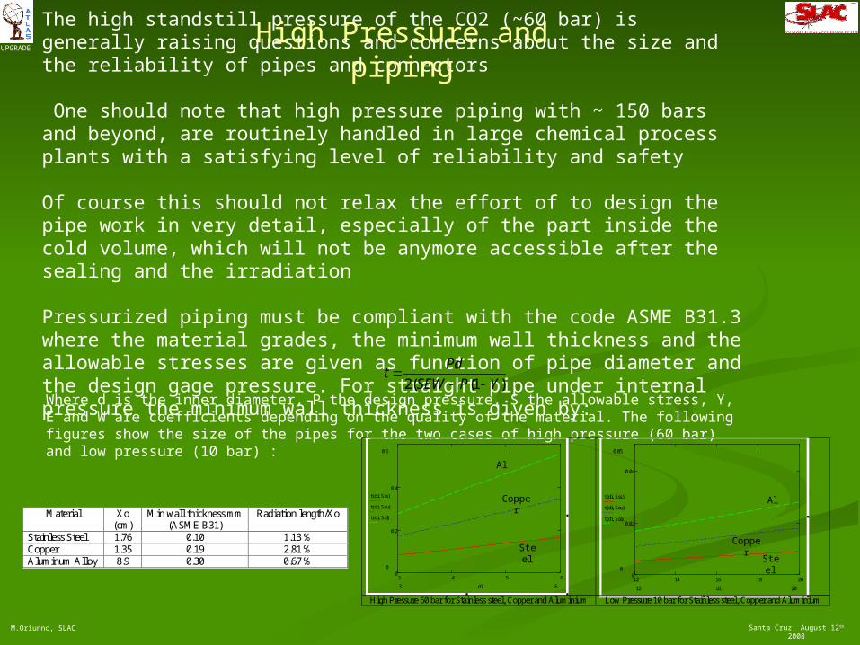
The high standstill pressure of the CO2 (~60 bar) is generally raising questions and concerns about the size and the reliability of pipes and connectors
One should note that high pressure piping with ~ 150 bars and beyond, are routinely handled in large chemical process plants with a satisfying level of reliability and safety
Of course this should not relax the effort of to design the pipe work in very detail, especially of the part inside the cold volume, which will not be anymore accessible after the sealing and the irradiation
Pressurized piping must be compliant with the code ASME B31.3 where the material grades, the minimum wall thickness and the allowable stresses are given as function of pipe diameter and the design gage pressure. For straight pipe under internal pressure the minimum wall thickness is given by:
)1((2 YPSEW
Pdt
Where d is the inner diameter, P the design pressure, S the allowable stress, Y, E and W are coefficients depending on the quality of the material. The following figures show the size of the pipes for the two cases of high pressure (60 bar) and low pressure (10 bar) :
High Pressure and piping
3 4 5 60
0.2
0.4
0.6
0
t di Sss( )
t di Scu( )
t di Sal( )
63 di 12 14 16 18 20
0
0.02
0.04
0.05
0
t di Sss( )
t di Scu( )
t di Sal( )
2012 di High Pressure 60 bar for Stainless steel, Copper and Aluminium Low Pressure 10 bar for Stainless steel, Copper and Aluminium
Copper
Steel
Al
Copper
Steel
AlMaterial Xo
(cm) Min wall thickness mm
(ASME B31) Radiation length/Xo
Stainless Steel 1.76 0.10 1.13 % Copper 1.35 0.19 2.81 % Aluminum Alloy 8.9 0.30 0.67 %

Santa Cruz, August 12th 2008
UPGRADE
M.Oriunno, SLAC
We can adopt for CO2 the same distribution used for the C3F8.
The Inner detector is subdivide in four quadrant fed independently by a 30/34 mm liquid line and a 72/76 mm vapor line.
Distribution racks fan in to ~ 50 liquid lines 4/6 mm and fan out 18/20 mm vapor lines.
The racks contain also the pressure and the back pressure regulators valve which set, independently for each channel, the mass flow and the evaporation temperature
Pressure drops calculations
Phase # channels Mass flow per channel (g/s) Max Length (m) Pipe ID (mm) Pressure drop (mbar)
Compressor to Racks liquid 4 250 177 30 220Racks to Inner Detector liquid 200 5 25 4 534Internal piping Inner detetctor liquid/vapor 200 5 ~ ~Inner Detector to racks vapor 200 5 25 18 8Racks to Compressor vapor 4 250 177 72 91
pressure drops

Santa Cruz, August 12th 2008
UPGRADE
M.Oriunno, SLAC
Conclusions
Plan to develop at SLAC an US ATLAS CO2 cooling facility
Blown CO2 system in construction -> expected to run end of September
Larger plant in design phase, main components have been sized
Preliminary calculations shows that for the final ATALSup ID, adopting CO2 in a vapor-compression cycle similar to the present plant running with C3F8, is feasible and offers many advantages due to the better physical properties of CO2.
It provide also enough margin to eliminate the weak points shown so far by the present C3F8 system
It fit well in super high irradiated environment like SLHC
It minimize the unavoidable take of risk stemming from the adoption of too many technological unknowns.