sanjay b. patil - construction | mining |...
TRANSCRIPT
For Authorised Use Only
SANJAY B. PATILSANJAY B. PATILSANJAY B. PATILSANJAY B. PATIL
JAMBREJAMBREJAMBREJAMBRE HYDRO ELECTRIC PROJECTHYDRO ELECTRIC PROJECTHYDRO ELECTRIC PROJECTHYDRO ELECTRIC PROJECT
1 x 2000 KW1 x 2000 KW1 x 2000 KW1 x 2000 KW
TENDER DOCUMENT TENDER DOCUMENT TENDER DOCUMENT TENDER DOCUMENT
NO.NO.NO.NO.SBPSBPSBPSBP----01010101/2016/2016/2016/2016----17171717
VOLUME VOLUME VOLUME VOLUME –––– IIIIIIII
SCOPE OF SCOPE OF SCOPE OF SCOPE OF SUPPLY,SUPPLY,SUPPLY,SUPPLY,
TECHNICAL SPECIFICATIONS TECHNICAL SPECIFICATIONS TECHNICAL SPECIFICATIONS TECHNICAL SPECIFICATIONS
& GTP& GTP& GTP& GTP
NAME OF WORK :NAME OF WORK :NAME OF WORK :NAME OF WORK : JAMBREJAMBREJAMBREJAMBRE HYDRO ELHYDRO ELHYDRO ELHYDRO ELECTRIC PROJECTECTRIC PROJECTECTRIC PROJECTECTRIC PROJECT
: Design, Manufacture, Test at Shop, Supply at site including
Transport, handling, loading/unloading, Installation, Putting to
Operation and Supervision during Erection, Testing, Commissioning
and Setting to Operation of Turbine/Generator sets along with all
E&M equipment required for Hydel power station and switchyard
for JAMBREJAMBREJAMBREJAMBRE HYDRO ELECTRIC PROJECTHYDRO ELECTRIC PROJECTHYDRO ELECTRIC PROJECTHYDRO ELECTRIC PROJECT(1X2MW)(1X2MW)(1X2MW)(1X2MW)::::
OFFICE OFFICE OFFICE OFFICE ADDRESS:ADDRESS:ADDRESS:ADDRESS: PRICE :PRICE :PRICE :PRICE : Rs. Rs. Rs. Rs. 11115000/5000/5000/5000/---- PerPerPerPer
SANJAY B. PATIL
R.S.NO.171 E WARD,
1 A Mahaveer College Chowk,
Nagala Park, Kolhapur-416003
Ph. 91-231-2650999,2657999
Email – [email protected]

JAMBREJAMBREJAMBREJAMBRE HYDRO ELECTRIC PROJECTHYDRO ELECTRIC PROJECTHYDRO ELECTRIC PROJECTHYDRO ELECTRIC PROJECT
TENDER DOCUMENT TENDER DOCUMENT TENDER DOCUMENT TENDER DOCUMENT
NO.NO.NO.NO.SBPSBPSBPSBP----01010101/2016/2016/2016/2016----17171717
VOLUME VOLUME VOLUME VOLUME –––– IIIIIIII
NAME OF WORK :NAME OF WORK :NAME OF WORK :NAME OF WORK : JAMBREJAMBREJAMBREJAMBRE HYDRO ELECTRIC PROJECTHYDRO ELECTRIC PROJECTHYDRO ELECTRIC PROJECTHYDRO ELECTRIC PROJECT
: Design, Manufacture, Test at Shop, Supply at site including
Transport, handling, loading/unloading, Installation, Putting to
Operation and Supervision during Erection, Testing, Commissioning
and Setting to Operation of Turbine/Generator sets along with all
E&M equipment required for Hydel power station and switchyard
for JAMBREJAMBREJAMBREJAMBRE HYDRO ELECTRIC PROJECT:HYDRO ELECTRIC PROJECT:HYDRO ELECTRIC PROJECT:HYDRO ELECTRIC PROJECT:
ISSUED TO M/s.ISSUED TO M/s.ISSUED TO M/s.ISSUED TO M/s. ________________________________________________________
________________________________________________________
________________________________________________________
Date:Date:Date:Date: __ / __ / ____
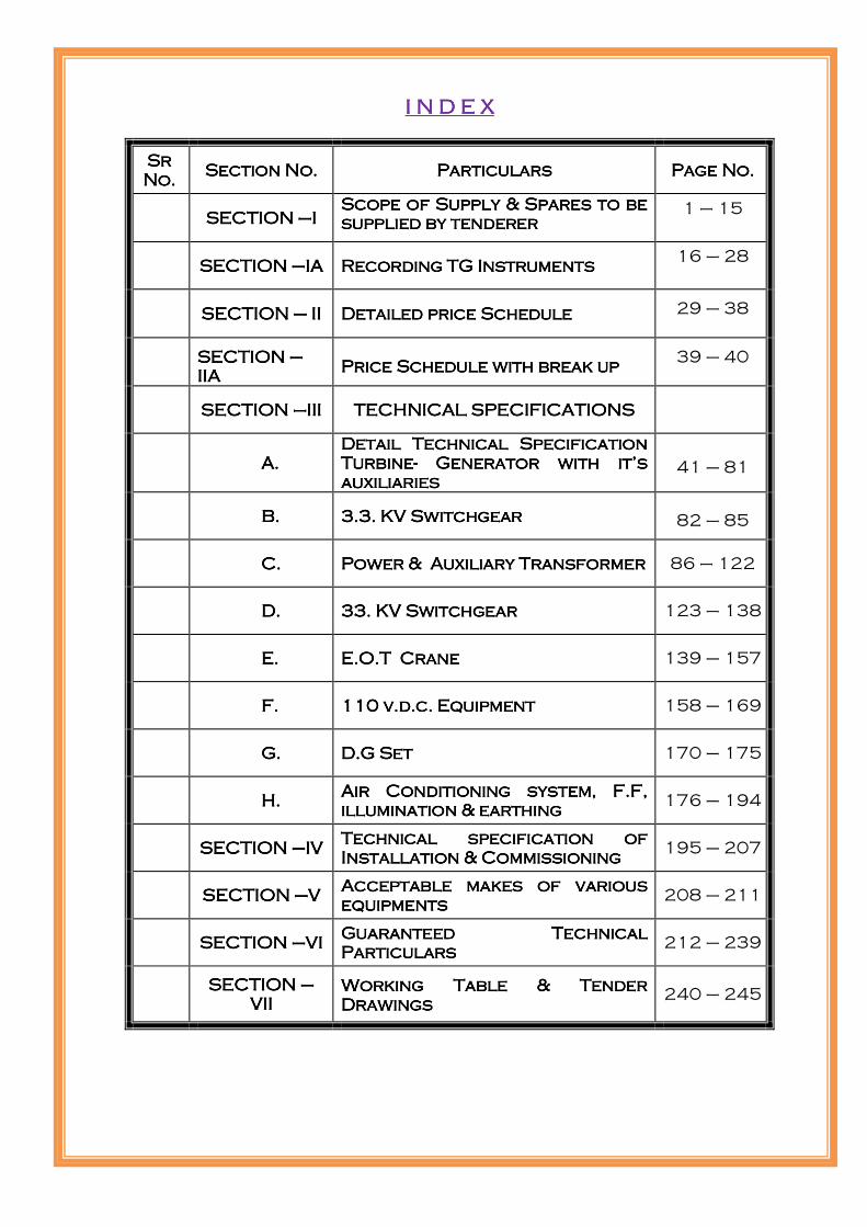
I N D E XI N D E XI N D E XI N D E X
Sr Sr Sr Sr
No.No.No.No. Section No.Section No.Section No.Section No. ParticularsParticularsParticularsParticulars Page No.Page No.Page No.Page No.
SECTION SECTION SECTION SECTION ––––IIII ScoScoScoScope of Supply & Spares to be pe of Supply & Spares to be pe of Supply & Spares to be pe of Supply & Spares to be
supplied by tenderersupplied by tenderersupplied by tenderersupplied by tenderer 1 – 15
SECTION SECTION SECTION SECTION ––––IIIIAAAA Recording TG InstrumentsRecording TG InstrumentsRecording TG InstrumentsRecording TG Instruments 16 – 28
SECTIONSECTIONSECTIONSECTION –––– IIIIIIII Detailed price ScheduleDetailed price ScheduleDetailed price ScheduleDetailed price Schedule 29 – 38
SECTION SECTION SECTION SECTION ––––
IIIIIIIIAAAA Price Schedule with break upPrice Schedule with break upPrice Schedule with break upPrice Schedule with break up
39 – 40
SECTION SECTION SECTION SECTION ––––IIIIIIIIIIII TECHNICAL SPECIFICATIONSTECHNICAL SPECIFICATIONSTECHNICAL SPECIFICATIONSTECHNICAL SPECIFICATIONS
AAAA.... DetailDetailDetailDetail Technical Specification Technical Specification Technical Specification Technical Specification
TurbineTurbineTurbineTurbine---- GeneratoGeneratoGeneratoGenerator with it’s r with it’s r with it’s r with it’s
auxiliariesauxiliariesauxiliariesauxiliaries 41 – 81
BBBB.... 3.3. KV Switchgear3.3. KV Switchgear3.3. KV Switchgear3.3. KV Switchgear 82 – 85
CCCC.... Power & Auxiliary TransformerPower & Auxiliary TransformerPower & Auxiliary TransformerPower & Auxiliary Transformer 86 – 122
DDDD.... 33. KV Switchgear33. KV Switchgear33. KV Switchgear33. KV Switchgear 123 – 138
EEEE.... E.O.T CraneE.O.T CraneE.O.T CraneE.O.T Crane 139 – 157
FFFF.... 110 v.d.c. Equipment110 v.d.c. Equipment110 v.d.c. Equipment110 v.d.c. Equipment 158 – 169
GGGG.... D.G SetD.G SetD.G SetD.G Set 170 – 175
HHHH.... Air Conditioning system, F.F, Air Conditioning system, F.F, Air Conditioning system, F.F, Air Conditioning system, F.F,
illumination & earthingillumination & earthingillumination & earthingillumination & earthing 176 – 194
SECTION SECTION SECTION SECTION ––––IVIVIVIV Technical specification of Technical specification of Technical specification of Technical specification of
Installation & CommissioningInstallation & CommissioningInstallation & CommissioningInstallation & Commissioning 195 – 207
SECTION SECTION SECTION SECTION ––––VVVV Acceptable makesAcceptable makesAcceptable makesAcceptable makes of various of various of various of various
equipmentsequipmentsequipmentsequipments 208 – 211
SECTION SECTION SECTION SECTION ––––VVVVIIII Guaranteed Technical Guaranteed Technical Guaranteed Technical Guaranteed Technical
ParticulaParticulaParticulaParticularsrsrsrs 212 – 239
SECTION SECTION SECTION SECTION ––––
VVVVIIIIIIII
Working Table & Tender Working Table & Tender Working Table & Tender Working Table & Tender
DrawingsDrawingsDrawingsDrawings 240 – 245

SANJAY B. PATILSANJAY B. PATILSANJAY B. PATILSANJAY B. PATIL
JAMBREJAMBREJAMBREJAMBRE HYDRO ELECTRIC PROJECTHYDRO ELECTRIC PROJECTHYDRO ELECTRIC PROJECTHYDRO ELECTRIC PROJECT
1 x 1 x 1 x 1 x 2020202000 KW00 KW00 KW00 KW
SECTION - I
SCOPE OF SUPPLY & SPARES TO BE
SUPPLIED BY TENDERER

SANJAY B. PATIL, KOLHAPUR JAMBRE HEP
SIGNATURE OF SUPPLIER SIGNATURE OF PURCHASER PAGE 1
SECTION - I
DETAILED SCOPE OF SUPPLY AND SCHEDULE OF EQUIPMENT
INDICATIVE LIST OF THE PLANT AND EQUIPMENT, NOT LIMITED TO, TO BE SUPPLIED BY THE
TENDERER
Sr.No
Description Qty. Unit
1.0 TURBINE & GENERATOR PLANT
1.1 Turbine:- HORIZONTA FRANCIS / SUITABLE
TURBINE of rated output not less than 2000 kW+10% for
27 meter design Head , rated discharge of 9.33 cumecs ,
with Governor and associated equipments complete with
Turbine auxiliaries comprising of compressed air system,
cooling water system, drainage and dewatering system,
H.M.C., servomotor, oil and water piping, valves, strainer,
bends, flow meter relay etc. complete.
1 Sets
1.2 Main Inlet Valve:- Butterfly type valve of suitable dia.
For suitable for connection 1800mm ID Penstock Along
with bye pass valves , drain valves , man holes , inlet pipe,
outlet pipe, dismantling joint, servomotor, O. P. U.
Control cabinet etc. complete.
1 Sets
1.3 Gear Box if required 1 no
1.4 Hydro Generator:- Horizontal shaft synchronous
alternator of capacity 2310 KVA+10% continuous
overloading facility at 0.866 p.f. under excited. 3.3 KV,
50Hz, three phase suitable for coupling to above
mentioned turbine with brushless excitation system with
Automatic voltage regulator etc. complete, with Generator
auxiliaries comprising S.S.G. unit, H.S. Lubrication
system, brake/ jack system, Fly Wheel stator encloser,
railing & coverings, coolers, heaters, cables etc. complete.
1 Sets
2.0 3.3 KV Switchgear comprising control & relay panels
suitable for computerized control system consisting of as
per SLD.
2.1 3.3 KV VCB Circuit breaker cubicle 2 No.
3.3 KV cubicle for P.T. WITH Draw out Type P.T. 2 Core 3.3 KV/√3,110 V/√3,110 V/√3 , ht FUSE etc.
1 No.

SANJAY B. PATIL, KOLHAPUR JAMBRE HEP
SIGNATURE OF SUPPLIER SIGNATURE OF PURCHASER PAGE 2
3.3 KV CT having suitable current ratio with 4 core for
protection & metering etc. 2 Sets Sets
2.2 3.3 KV neutral grounding transformer(NGT) cubicle with isolator , 3.3 KV CT having suitable current ratio with 4 core for protection & metering etc.
1 No.
2.3
3.3 KV LAVT cubicle with isolator , bus LA and capacitor 3.3 KV CT having suitable current ratio with 4 core for protection & metering etc.
1 No.
3.0 GENERATOR, TRANSFORMER & FEEDER
PROTECTION AND SYNCHRONIZING PANEL (
COMPRISING NUMERICAL PROTECTION RELAYS )
suitable for computerized control system
1. Generator Protection Panels, comprising of Protection
scheme, alarm facias, meters, relays suitable for
computerized control system complete wired & tested
as per specification.
1 Sets
2. Transformer panel comprising, Protection scheme,
alarm facias, meters, relays suitable for computerized
control system complete wired & tested as per
specification.
1 Set
3. Line protection cubicles for 33 KV lines comprising
protection scheme, alarm facia, meters, relays suitable
for computerized control complete wired & tested as
per specification.
1 Set
4. Synchronizing system comprising, protection scheme,
alarm facias, meters, relays suitable for computerized
control system complete wired & tested as per
specification.
1 Set
5. Unit control board for unit operation in auto , manual
and remote mode. 1 Set
4.0 REMOTE CONTROL SYSTEM
Complete in all respect Including INTERFACES, and other
material etc required for achieving total control of the plant
in two levels(Local And Remote) of control with complete
PLCC equipt suitable to the one installed by M.S.E.B. at
receiving sub-station.
1
Set

SANJAY B. PATIL, KOLHAPUR JAMBRE HEP
SIGNATURE OF SUPPLIER SIGNATURE OF PURCHASER PAGE 3
5.0 POWER TRANSFORMER
Power Transformer of capacity 2.5 MVA, 3 Ph., 33 KV/ 3.3
KV , 50 Hz., ONAN type with “ON” load tap changer,
RTCC cubical suitable for power cable connections on HT
and L.T. side with first filling of oil & accessories. And
Cable box.
1 No.
6.0 33 kV INDOOR SWITCHGEAR EQUIPMENTS 1 No
33 KV draw out type Switchgear with control and protection
system ( as per SLD. )suitable for computerized control
system
2 NOS -33 KV VCB DRAWOUT , Circuit breaker cubicle AS PER specification.
1 SET 1 NOS.-33 KV cubicle for P.T. WITH Draw out Type P.T. 2 Core 33 KV/√3,110 V/√3,110 V/√3 , ht FUSE etc.
1 SET -33 KV CT having suitable current ratio with 4 core for protection & metering etc. 1set
1 no- 33 KV rated insulation class BIL,170 kv Peak,50 A,
25 KA,3 Ph.,50 Hz, double break center pole rotating , Motorized outdoor isolator earth blades.
1 NO
Supply of Metering Kiosk / outdoor CT and PT as
per MSEDCL direction/ specifications. 1 SET
30 KV ,10 KA , Single Phase, 50 Hz., Valve type station
class, outdoor type lightening arrester with accessories. 3 No.
Bus Bar material including ACSR conductor, insulators etc.,
complete. L.S.
Switchyard galvanized steel structure, tack off structure
with foundations etc., complete. L.S.
Marshaling box Adequate
Junction Boxes for C.T. and P.T. Adequate
7.0 415 V A.C. SWITCHGEAR PANEL
Indoor type 415 V, A.C. Distribution board Panel
comprising of two Nos., of incoming A.C.B., of suitable
capacity with auto change over system, Bus Bars, metering
equipments and 20 to 25 Nos., of outgoing switch fuse units
with ammeters, including manual/ auto change over for
U.A.T. to D.G. Set A.C. supply complete with required
accessories.
1 Set

SANJAY B. PATIL, KOLHAPUR JAMBRE HEP
SIGNATURE OF SUPPLIER SIGNATURE OF PURCHASER PAGE 4
8.0 110 VOLT D.C. EQUIPMENTS
Lead Acid Batteries having capacity of 110 V/ 300 AH with
required accessories , wooden stand , DC volt meter, hydro
meter etc.
Battery charger suitable for 110 KV, 300 AH, capacity
Batteries, with float & float cum boost charger with
accessories.
110 KV D.C., Distribution Board with 30 Nos., of outgoing
feeders with accessories.
1 Set
9.0 UNIT AUXILIARY TRANSFORMER
Unit Auxiliary Transformer 100 KVA, 33 KV / 415 V, 3
Phase, 50 Hz., outdoor type with first filling of oil with oil
accessories. Suitable for 33 KV cable termination.
1 No.
10.0 POWER AND CONTROL CABLES
3.3 KV H.T. Power Cables single core 350 Sq. mm ,XLPE insulated copper, 5 KV (E) Grade, armored
33 KV H.T. Power Cables 3 core 185 Sq. mm ,XLPE insulated copper, armored.
L.T. Power & Controls Cables, Screened Cables, A.C. auxiliary power supply cables, Trays, Racking, Trench Covers and suitable clamps for fixing cable trays with accessories etc. complete.
All cables shall be of copper.
lot Set
11.0 OTHER ITEMS
11.1
E.O.T. Crane of suitable capacity, to be decided by bidder,
pendent operated , A.C., 415 V ± 10%, 3 Phase, 50 Hz.,
Power Supply, with down shop leads etc. ,complete.
1 No
11.2 63 KVA, D.G. Set, 415 V, 3 Phase out door type , silent. 1 No
11.3 Power House and Switchyard Earthmats , earth grid , And
lightening protection. Lot Lot
11.4 Power House & Switchyard lighting & Construction power
supply. Lot Lot
11.5 Fire Fighting Equipments , rubber mat etc. Set Set
11.6 Communication System and furniture. Lot Lot
11.7 Workshop Equipments / TOOLS Set Set
11.9 Air Conditioning for control room Lot Lot

SANJAY B. PATIL, KOLHAPUR JAMBRE HEP
SIGNATURE OF SUPPLIER SIGNATURE OF PURCHASER PAGE 5
12.0 TRAINING AND INSPECTION
12.1 Training for Purchaser’s Engineer
12.2 Inspection at Works by Purchaser’s Engineers
12.3 Factory Inspector & Electrical Inspector Inspection
Clearance of pollution board and all other clearances.
13.0
ERECTION, TESTING, AND COMMISSIONING AND
PUTTING TO SATISFACTORY OPERATION OF
SUPPLIED EQUIPMENT AND SYSTEMS. BY
PROVIDING COMPETENT ENGINEERS AND OTHER
SKILLED/ UNSKILLED/ SEMISKILLED WORKERS,
CONSUMABLES AND MAINTENANCE SPARES FOR
OPERATION AND MAINTENANCE FOR SIX (6)
MONTHS PERIOD FOR JAMBRE H.E.P. ( 1 X 2000 KW)
AFTER COMMISSIONING OF THE UNIT FOR
COMMERCIAL USE FOR SBP, KOLHAPUR
Job Lump
sum
15 Mandatory tools and spares as per list attached annexure-I & II
Lum sum
Note - The list above is indicative and supplier’s offer shall be complete in all respect for
equipment being offered.

SANJAY B. PATIL, KOLHAPUR JAMBRE HEP
SIGNATURE OF SUPPLIER SIGNATURE OF PURCHASER PAGE 6
NOTE
C. REQUIREMENTS – SPECIFIC
1) While designing entire plant the ratings/size mentioned in tech. Specifications for major
equipments viz. turbine, Generator, main power transformer & its voltage levels, size of B.F.
valve, rated voltage levels of A.C. & D.C. shall not be changed. However if ratings of other
associated auxiliaries, equipments could be changed as per contractors design, the
Tenderer/contractor should furnish the design, Engineering Drawings, technical data for prior
approval of the purchaser.
2) The Tenderer/Contractor should take cognizance of the present status of works which are
fully/partially completed & he should interface all above works to complete the entire plant in
all respect and also co-ordinate with Civil, Electrical & Mechanical works not covered in this
specification but generally needed for such power stations.
3) The Tenderer/Contractor shall carry out O & M for the period of upto six months after
successful commissioning of entire plant as per availability of water in reservoir and according
to Irrigation release programmed decided by the Irrigation Authorities/Purchaser. Six months
O & M shall be completed within one-year period after commissioning of entire plant. During
this one-year period if O & M cannot be carried out due to non-availability of water, evacuation
arrangement and decision of further extension for O & M period will be mutually decided.
4) The scope of work under this specification also includes additional Investigations, Planning &
engineering and it shall be sole responsibility of the Contractor for completely covering all the
works, equipments, accessories etc. Specified in the specification and shall also include all
necessary works, equipments, accessories, works even though not specifically mentioned in the
specification but which are essential for the satisfactory completion of the entire power station.
Design, Technical specification along and drawings of such works, equipments etc. shall be
furnished for purchaser’s approval.
5) The drawings enclosed with the tender documents are purely indicative & of tentative nature &
are prepared for tender purpose only. The Tenderer/Contractor shall have to prepare the
detailed drawings as per design & requirement of the scheme according to technical
specification. Necessary components, equipments that have not been indicated shall be added
to fulfill the requirement of the scheme.

SANJAY B. PATIL, KOLHAPUR JAMBRE HEP
SIGNATURE OF SUPPLIER SIGNATURE OF PURCHASER PAGE 7
6) Some of the limitations as per the actual site conditions, which are to be verified by
Contractor during his site visit are as below:
Pressure rise shall not exceed 25 % in the water conductor system including pipes embedded
in the dam.
7) Machines shall be suitable to be operated under following condition.
1. SANJAY B. PATIL, KOLHAPURhave appointed M/S. DIWAN KHADILKAR
CONSULTANTS PVT. LTD. Consulting Engineer, Kolhapur as their Consultants on designs,
inspections, testing, manufacture, erection, testing and commissioning, quality assurance,
performance acceptance, project management etc. Therefore all these activities shall be subject
to review of Consultant. Supplier/Manufacturer/ Contractor to note the requirement.
2. Entire plant and machinery shall be designed for thirty five years of operational life of the plant
without major modifications or repairs. Plant is susceptible for cyclic and complex loadings.
Frequent starting and stopping to meet the critical loads Automatic frequency and power
regulation mode. Frequency and voltage regulation mode.
3. Frequency and voltage regulation mode under which the unit shall develop full rated output
shall be 47.5 to 51.5 Hzs., and 3.3KV±10% of rated generator voltage respectively.
4. Total time for starting from standstill to rated full load for generating set shall not exceed for
time suitable for pressure rise and negative pressure transient of water conductor system
including starting of all auxiliaries subject to restrictions of pressure rise and speed rise.
Flywheel effect shall be accordingly designed.
5. Availability of the generating sets for first two years shall be 92% and thereafter 95%. Similarly
reliability shall be 95% first two years and 98% for rest of the life.
6. Availability in a year =
(Service hours in one year +Reserve service hours in the same year) ÷ Total hours in a year.
Reliability in a year =
(Total attempted starts–Total starts failure) ÷ Total attempted starts.
8. The turbine prototype dimensions shall be so designed that majoration of power on account of
possible efficiency step up shall be in accordance with IEC 995/1991.

SANJAY B. PATIL, KOLHAPUR JAMBRE HEP
SIGNATURE OF SUPPLIER SIGNATURE OF PURCHASER PAGE 8
9. Number of start and stop per day –max to 6 times: Number of trip out other than overspeed—
12 times per year; likely runaway conditions per year—once.
10. Maximum admissible steady state power output pulsation at generator terminals shall not be
more than ±1.5% of actual active power. Machines shall be designed for peak load, base load
and solo mode operations.
11. Manufacturer should have conducted model test from recognized laboratory on which the
design is based. Such model test results shall be furnished along with the bid.
12. Machine and equipment shall be designed to with stand earthquake forces as follows:-
Horizontal direction == 0.3g
Vertical direction == 0.15g
Where g is the gravitational acceleration.
Maximum air temperature -----46 degree Celsius.
Minimum air temperature-------6 degree Celsius.
Relative Humidity 100% during monsoon.

SANJAY B. PATIL, KOLHAPUR JAMBRE HEP
SIGNATURE OF SUPPLIER SIGNATURE OF PURCHASER PAGE 9
LIST OF I.S.S & I.E.C.
Exact applications of I.S.S & I.E.C. are enumerated in the tender documents. Following is the list of
I.S. & IEC. The EPC contractors/ Manufacturer to note these standards in executing the work of
JAMBRE HEP (1 X 2.00 MW).
List of power station equipment with their acceptable Standers, Acceptable to MNRE & AHEC Roorkee.
Sr. No. Name of Equipment Standards to which equipment conforms
1 Turbines IEC 60034-1:1983,IEC 61366-1:1998,IEC61116-1992
2 Generators IS 4889-1968,IS4722-2001,IS12800(part3)1991
3 Protective Relays ANSI 50N / 51N
4 PLC IEC 61131-3
5 SCADA System IEC 60870-5-101
6 Excitation System GB 1085-89
7 Panel IS 8623 IV & IP 51
8 MIV IS7326-1902
9 Cables IS 8130/1984
10 Pumps IS 6392
11 Power Transformers IS 2026,IS3156-1992,IS2705-1992
12 Current Transformers IS 2705
13 Potential Transformers IS 3156
14 HT, LT circuit breakers IS 2516
15 Governor IS 4889-1968,IEC-60308
16 AVR IS 4889-1968
17 Auto Synchronization IS 4889-1968
18 Motor IS 325
19 Batteries IS 9001
20 Crane IS 3815
21 Field acceptance Test IEC60041:1991

SANJAY B. PATIL, KOLHAPUR JAMBRE HEP
SIGNATURE OF SUPPLIER SIGNATURE OF PURCHASER PAGE 10
Sr. No. List of I.E.C. Standards
1 IE RULE 1956 (REV 2006)
2 ELECTRICITY Act 2003
2.1 STANDARDS
IEC 60041 International code for Field Acceptance Tests of Hydraulic Turbines
IEC 60308 International code for testing of speed governing systems for hydraulic turbines
IEC 60545 Guide for commissioning, operation & maintenance of hydraulic turbine
IEC 60994 Guide for field measurement of vibrations and pulsations of hydraulic machines
IEC 60995 Determination of prototype performance from model acceptance test of hydraulic machines with consideration of scale effects
IEC 60193 International standard – Hydraulic turbines - Model acceptance tests
IEC 60041 International standard field acceptance tests of hydraulic turbines
IEC 60609 P 1 Cavitations pitting evaluation in hydraulic turbines, storage turbines and pump-turbines, Part 1.
ASME Boiler and Pressure Vessel Code, Section VIII
IS 12800 Guidelines for Selection of Turbines, Preliminary dimensioning and layout of Surface Hydro Electric Power house
IS : 1271 Classification of insulating materials for electrical machinery
IS : 2379 Colour code for the identification of pipelines
IS : 5 Colour for ready mixed paints and enamels
IS : 226 Structural steel (standard quality) (fifth revision)
IS : 1538 Cast Iron fittings for pressure pipe for water, gas and sewage
IS : 6392 Steel pipe flange
IS : 2906 Sluice valves for water works
IS : 2002 Medium tensile steel plate used for welding, flame cutting and flanging in hot condition
IS: 2049 Colour code for identification for wrought steel for general engineering purposes
IS: 1030 Cast steel
IS: 28 Bronze
IS : 1239 G.I. pipes Part 1, Part 2
Note : The latest edition of the above codes shall be referred.

SANJAY B. PATIL, KOLHAPUR JAMBRE HEP
SIGNATURE OF SUPPLIER SIGNATURE OF PURCHASER PAGE 11
ANNEXURE I
LIST OF MANDATORY SPARES TO BE SUPPLIED BY THE CONTRACTOR
Sr.No Description Qty.
1.0 MAIN TURBINE AND GENERATOR PLANT AND ITS ASSOCIATD EQUIPMENT
1.1 TURBINE EQUIPMENT (1 Set)
1. Fully machined guide vanes with levers, bushes, housing 2 Nos. 2. Fully machined babitted pads for guide bearing. 1 Set 3. Gasket, seals & packing of each type 1 Set 4. Moulded rubber packing rings for shaft gland. 1 Set
5. Piston rings for runner servomotor & guide vane servomotors.
1 Set
6. Shear pins for the guide apparatus. 1 Set 7. Runner blade assembly 1 Set 8. Pressure gauge of each type. 1 No.
1.2 FOR GOVERNOR AND OIL PRESSURE SYSTEM (1 Set) 1. Oil pump complete with motor 1 Set 2. Pilot and control valve complete 1 Set 3. Transducers 1 Set 4. Pump unloaded and safety relief valve 1 Set
5. Float switches, pressure, flow and temperature relays of each type used.
1 Set
6. Solenoids for each type of solenoid valve used. 1 Set 7. Fuses of each type used. 2 Sets 8. Each kind of filter used. 2 Sets
9. Complete set of all packing, gasket and jointing material used.
2 Sets
10. Ten percent ( 10 % ) of all bolts, screws, nuts and washers upped and including M 30
2 Sets
1.3 HYDRO MECHANICAL CABINET (1 Set) 1. Electro hydraulic transducer 1 No. 2. Feedback potentiometers. 1 No. 3. Pilot valve sleeve & needle. 1 Set 4. Coil for electromagnetic transducer. 1 No. 5. Oil filter sleeve. 1 Set 6. Electro tachometer 1 No. 7. Balance indicator 1 No. 8. Speed setting indicator 1 No. 9. Micro switch for contact device 1 No 10. Micro switch for over speed device 1 No
1.4 MAIN INLET VALVE (1 Nos.) 1. Services seal with all fixing 1 Set 2. Servomotor piston rings and packing. 1 Set 3. Control solenoids of each type used. 1 Set 4. Limit switch of each type used. 1 Set 5. Valve of each type used. 1 Set
6. Complete set of all packing, gasket and jointing material used thought out the valve.
1 Set

SANJAY B. PATIL, KOLHAPUR JAMBRE HEP
SIGNATURE OF SUPPLIER SIGNATURE OF PURCHASER PAGE 12
7. Ten percent ( 10% ) of all bolts, screws, nuts and washers upped and including M30.
1 Set
1.6 DEWATERING AND DRAINAGE SYSTEM (common for Station) Standard spares for pumps & motors.
1 Set
1.7 COOLING WATER SYSTEM. (for 1 Set) Standard spares for pumps & motors.
1 Set
2.0 GENERATOR ( One No) - Each set consisting of following. 1. D E bearing pads. 1 Set. 2. N D E bearing pads. 4 Nos. 3. Dial type thermometers. 2 Nos. 4. Thermostat. 4 Nos. 5. Heater element. 6. Pole keys. 2 Sets.
7. Brake shoe. 1 No.
8. Plug in type oil cooler unit for combined thrust & guide bearing.
1 No.
9. Brush holders. Carbon brushes. 1 Set.
2.1 BRUSH LESS EXCITATION SYSTEM. (1 Set) - One Set consisting of following
1. Motorized potentiometer. 1 No.
2. Gate circuit. 1 No. 3. Pulse final stage of power pack. 1 No. 4. Pulse supervision. 1 No. 5. Intermediate pulse amplifier & power pack. 1 No. 6. Digital voltage regulator. ( D.V.R. ) 1 No. 7. Relays ( Latching auxiliary & time delay relays. 1 Set.
2.2 SPARE FOR FIELD contactor. 1. Closing coil. 1 No. 2. Tripping coil. 1 No. 3. Moving contact. 1 No. 4. Field discharge resistor unit 1 No. 5. Aux. Contact block. 1 No.
3.0A 3.3 KV SWITCHGEAR . (1 Set) 1. One Set consisting of following. 2. Bus insulations. Panel meters one each 12 Nos. 3. Spring charging motor one set 1 set. 4. Indicating lamp each 12 Nos. 5. 3.3 K.V., 10 K.A. lightening arrester. 1 No. 6. Surge capacitor. 1 No.
7. 3.3 KV / 110 V Voltage transformer for DVR. √3 / √3
1 No.
8. 3.3 KV / 110 V Voltage transformer for metering . √3 / √3
1 No.
9. Isolating link. 6 No.
10. C. T's of appropriate rating for Generator Differential Protection, DVR, metering, over current, Overall Differential Protection etc. 6 Nos.
3.0B 33 KV SWITCHGEAR . (1 Set) 1. One Set consisting of following. 2. Bus insulations. Panel Meters one each type 12 Nos.

SANJAY B. PATIL, KOLHAPUR JAMBRE HEP
SIGNATURE OF SUPPLIER SIGNATURE OF PURCHASER PAGE 13
3. Panel indicating lamp each 3 Nos. 4. Spring charging motor 1 set 5. 30 K.V., 10 K.A. lightening arrester. 1 No. 6. Surge capacitor. 1 No.
7. 33 KV / 110 V Voltage transformer √3 / √3
1 No.
8. 33 KV / 110 V Voltage transformer for MSEDCL metering. √3 / √3
1 No.
9. Metering C.T.’s Of Appropriate Rating For MSEDCL . 1 No. 10. Isolating link. 6 No.
11. C.T.'s of appropriate rating for Generator Differential Protection, DVR, metering, over current, Overall Differential Protection etc.
6 Nos.
4.0 GENERATOR, TRANSFORMER, FEEDER SYNCHRONISING PANEL.
One set consisting of 1. Semaphore indicator. 2 Nos. 2. ODL lamps. 6 Nos. 3. Auxiliary relays. 16 Nos. 4. Fuse & links of various rating. 20 Nos. 5. Switches. 5 Nos. 6. Push button. 8 Nos. 7. Spare for annunciation. 4 Nos. 8. Digital timer, external plug type relay meter. 1 Set. 9. MCB, Rheostat. 1 Set.
5.0 RELAY AND METERING PANEL 1. Relay - Protective Relay , Auxiliary Relay. 1 of each kind. 2. Molded case circuit breaker 1 of each kind. 3. Meter 1 of each kind. 4. Fault, operation and Symbol indicator assembly 5 of each kind. 5. Lens for Symbol 5 of each kind. 6. Indicating lamp 10 % of installed quantity. 7. Process input output 2 of each kind. 8. Fuse 20 of each kind. 9. Control selector and Cut-off switch 1 of each kin. 10. Transducer 1 of each kind. 11. Wrapping label and marking strip 100 % of installed Quantity 12. Plug – in type connection accessories 1 pair of each kind. 13. Fiber card with optical Connector 2 of each kind. 14. Temperature detector 2 of each kind.
6.0 Crane
1. Limit switches 12 nos 2. Break pad 1 set 3. Remote Pendent One no 4. Auxiliary relays. 16 Nos. 5. Fuse & links of various rating. 20 Nos. 6. Switches. 5 Nos.
7.0 D G SET 1 set

SANJAY B. PATIL, KOLHAPUR JAMBRE HEP
SIGNATURE OF SUPPLIER SIGNATURE OF PURCHASER PAGE 14
ANNEXURE. II
LIST OF WORK SHOP TOOLS TO BE SUPPLIED BY THE CONTACTOR
Sr.No. Description Unit
1. Secondary injection kit 1 Set. 2. 5 KV motorized megger 1 No. 3. 1 KV Hand operated megger 1 No. 4. 500 V Hand operated megger 1 No. 5. Analog multimeter 1 No. 6. Digital multimeter with temperature measuring facility 1 No. 7. Phase sequence meter. 1 No. 8. Grinder (Hand) 1 No. 9. Crimpling tool for cable 1 No. 10. Bearing puller set 1 No. 11. Vacuum cleaner 1 No. 12. Timer (ms) 1 No. 13. Set of plain / flat (double ended) spanner. 1 Set. 14. Set of ring spanner 1 Set. 15. Set of Torque spanner 1 Set. 16. Set of screw driver 1 Set. 17. 8" pliers. 1 Set. 18. Hydraulic crimping tool up to 400 Sq. mm 5 Nos. 19. Hand crimping tool up to 16 Sq. mm 1 Nos. 20. 300 A capacity clip ON type Ammeter 1 No. 21. Electro static on line filter 1 No. 22. Governor , Bearings and Transformer oil testing kit 1 No. 23. Earth tester 1 No. 24. Single phase & 3 Phase voltage variance. 1 Set. 25. Laptop with 24B, 15” screen inbuilt modem for Internet
connections with software for setting Testing for Numerical relays
1 Set.
26. Special equipment and tools necessary for Installation, operation & maintenance of whole plant: Special tools for turbines Special tools for Generator General tools for Electrical equipment Balance tools for the whole plant
1 Lot
SANJAY B. PATIL, KOLHAPUR JAMBRE HEP
SIGNATURE OF SUPPLIER SIGNATURE OF PURCHASER PAGE 15
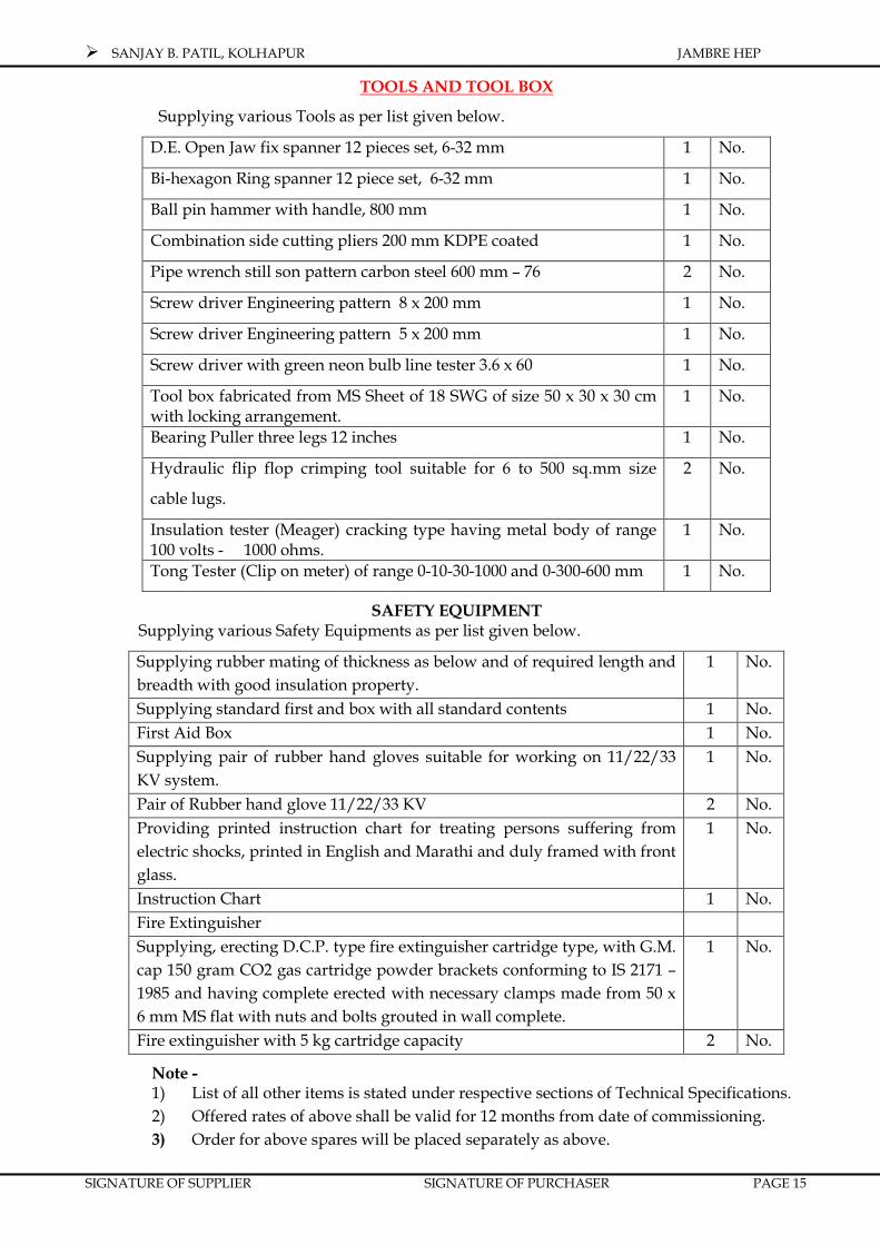
TOOLS AND TOOL BOX
Supplying various Tools as per list given below.
D.E. Open Jaw fix spanner 12 pieces set, 6-32 mm 1 No.
Bi-hexagon Ring spanner 12 piece set, 6-32 mm 1 No.
Ball pin hammer with handle, 800 mm 1 No.
Combination side cutting pliers 200 mm KDPE coated 1 No.
Pipe wrench still son pattern carbon steel 600 mm – 76 2 No.
Screw driver Engineering pattern 8 x 200 mm 1 No.
Screw driver Engineering pattern 5 x 200 mm 1 No.
Screw driver with green neon bulb line tester 3.6 x 60 1 No.
Tool box fabricated from MS Sheet of 18 SWG of size 50 x 30 x 30 cm with locking arrangement.
1 No.
Bearing Puller three legs 12 inches 1 No.
Hydraulic flip flop crimping tool suitable for 6 to 500 sq.mm size
cable lugs.
2 No.
Insulation tester (Meager) cracking type having metal body of range 100 volts - 1000 ohms.
1 No.
Tong Tester (Clip on meter) of range 0-10-30-1000 and 0-300-600 mm 1 No.
SAFETY EQUIPMENT Supplying various Safety Equipments as per list given below.
Supplying rubber mating of thickness as below and of required length and breadth with good insulation property.
1 No.
Supplying standard first and box with all standard contents 1 No. First Aid Box 1 No. Supplying pair of rubber hand gloves suitable for working on 11/22/33 KV system.
1 No.
Pair of Rubber hand glove 11/22/33 KV 2 No. Providing printed instruction chart for treating persons suffering from electric shocks, printed in English and Marathi and duly framed with front glass.
1 No.
Instruction Chart 1 No. Fire Extinguisher Supplying, erecting D.C.P. type fire extinguisher cartridge type, with G.M. cap 150 gram CO2 gas cartridge powder brackets conforming to IS 2171 – 1985 and having complete erected with necessary clamps made from 50 x 6 mm MS flat with nuts and bolts grouted in wall complete.
1 No.
Fire extinguisher with 5 kg cartridge capacity 2 No.
Note - 1) List of all other items is stated under respective sections of Technical Specifications. 2) Offered rates of above shall be valid for 12 months from date of commissioning. 3) Order for above spares will be placed separately as above.

SANJAY B. PATILSANJAY B. PATILSANJAY B. PATILSANJAY B. PATIL
JAMBREJAMBREJAMBREJAMBRE HYDRO ELECTRIC PROJECTHYDRO ELECTRIC PROJECTHYDRO ELECTRIC PROJECTHYDRO ELECTRIC PROJECT
1 x 1 x 1 x 1 x 2020202000 KW00 KW00 KW00 KW
SECTION - IA
RECORDING TG INSTRUMENTS

SANJAY B. PATIL, KOLHAPUR JAMBRE HEP
SIGNATURE OF SUPPLIER SIGNATURE OF PURCHASER PAGE 16
SECTION – I A INDICATING & RECORDING T-G INSTRUMENTS
Sr.No. Description of Item to be indicated /
measured
Device
type
Total quantity
per unit Location
TURBINE
1 Lake Water Level Indicator
2 Turbine Water Flow Measurement
3 Position of Intake Gate
4 Position of Main Inlet Valve
5 By Pass Valve Open
6 Pressure in Main Pipeline (Before Inlet
Valve)
7 Pressure in Main Pipeline
(After Inlet Valve)
9 G V position indicator
11 Main Governor Oil Pump ON / OFF
status.
12 Standby Governor Oil Pump ON / OFF
status.
13 Pressure in governor oil pressure
system
14 Pressure of regulating oil pressure
system
15 Pressure of regulating oil pressure
system
16 Level of oil in sump tank, if any
17 Unit speed indication (Speed indicator)
18 Unit Over speed Indicator
19 Speed Level setting indicator

SANJAY B. PATIL, KOLHAPUR JAMBRE HEP
SIGNATURE OF SUPPLIER SIGNATURE OF PURCHASER PAGE 17
20 Speed Droop setting indicator
21 Governor Speed Level Setting
22 Governor Speed Droop Setting
22A 12 Point annunciator for Turbine ANN
GENERATOR / TRANSFORMER
/LINE
23
Generator Drive end Bearing
Temperature sensor (Thrust & Guide
Bearing)
24
Generator Non-Drive end Bearing
Temperature sensor (Thrust & Guide
Bearing)
24A Main Lube Oil Pump ON / OFF status.
24 B Standby Lube Oil Pump ON / OFF
status.
25 Dial thermometers for generator,
bearings for alarm / trip
26
12 points indicator ( SCn )for stator
winding temperature and bearing
temperature
27 Generator heater ON/OFF indicating
Lamps
28 Brakes On / Off indication
29 Flow meter (water) / Pressure (oil) for
bearing cooling (if applicable)
30 Unit output meter (KW)
31 Unit KVAR meter with center zero
32 Unit voltmeter
33 Unit ammeter

SANJAY B. PATIL, KOLHAPUR JAMBRE HEP
SIGNATURE OF SUPPLIER SIGNATURE OF PURCHASER PAGE 18
34 Unit power factor meter (with center
zero)
35 Unit frequency meter
36 Unit energy meter (kWh)
37 Unit Circuit Breaker Open / Closing
Indicating Lamp
37-A Field breaker ON /OFF
38 Balance Indicator of AVR
39 AVR Auto / Manual Indicating Lamps
40 Outgoing breaker
41 Transformer Oil Temp
42 Transformer Wdg. temp
43 Grid Voltage
44 Grid breaker status
45 Grid isolator status
46 Unit Auto / Manual SW
47 Unit Local / Remote SW
48 24 W Annunciator For Generator.
49 8 W Annunciator For Transformer And
Outgoing Bkr.
50 Cooling Water booster Pump ON
/Off
NOTES:
1. The list is indicative only. The bidder/supplier may add as per his assessment. Quantities may be filled up by the bidder
2. Contractor to meet the minimum requirement for satisfactory monitoring and control of generating unit etc.

SANJAY B. PATIL, KOLHAPUR JAMBRE HEP
SIGNATURE OF SUPPLIER SIGNATURE OF PURCHASER PAGE 19
Sr.
No. Item indicated/recorded
Type of
instruments/device
Number provided
Remarks On or near the
equipment/locally
Unit Control Board At Mosaic
Board in
Control
room
Total At gen.
Gauge
panel
At unit
Control
Board
1. TEMPERATURES OF
Stator Winding One set
recorder
Stator teeth + indicator
24 point with digital
Scanner
Rotor Temperature indicator
Air Cooler inlet and outlet
air and cooling RTD
Inlet and outlet Signal scanner for same?
Thrust bearing pad. guide
bearings pads
• RTD
• Digital Scanners
• Indicators
Guide bearing oil reservoir
and cooling Water outlets.
• RTD
• Indicator
• Recorder

SANJAY B. PATIL, KOLHAPUR JAMBRE HEP
SIGNATURE OF SUPPLIER SIGNATURE OF PURCHASER PAGE 20
Sr.
No. Item indicated/recorded
Type of
instruments/device
Number provided
Remarks On or near the
equipment/locally
Unit Control Board At Mosaic
Board in
Control
room
Total At gen.
Gauge
panel
At unit
Control
Board
Cooling water at outlet of
the bearings
• RTD
• Indicator
Excitation transformer
winding • Indicator
2. PRESSURE
H.P. Oil lubrication system
Compressed air supply to
brakes
Oil in Jacking system
• PG .
• PG + RL
• PG
3. LEVELS OF
Oil in guide bearing oil
reservoir
Oil in guide bearing oil
reservoir.
Oil in jacking system.
• Sight gauge + RL
• Sight gauge + RL
• Sight gauge
4. FLOW OF
Water in common
discharge pipe of air
coolers.
Water in the discharge
pipe of lower guide
bearing oil coolers.
• Flow
• Flow

SANJAY B. PATIL, KOLHAPUR JAMBRE HEP
SIGNATURE OF SUPPLIER SIGNATURE OF PURCHASER PAGE 21
Sr.
No. Item indicated/recorded
Type of
instruments/device
Number provided
Remarks On or near the
equipment/locally
Unit Control Board At Mosaic
Board in
Control
room
Total At gen.
Gauge
panel
At unit
Control
Board
Water in Discharge pipe of
thrust and guide bearings
oil coolers.
• Flow
5. STATUS INDICATION VIZ.
Generator brakes 'ON /
OFF' Indicating lamps
Generator h eater 'ON /
OFF' Indicating lamps
HP oil lubrication pump
running / stand-still. Indicating lamps
Field breaker close / "pen Indicating lamps
Fire fighting system
operated / healthy Indicating lamps
6. OTHER ITEMS
Indication for automatic
voltage regulator, limit
positions and control in
progress etc.
Indicating lamps
DC voltmeter and
ammeter for static
excitation system
(including starting
excitation system)
Indicating instruments

SANJAY B. PATIL, KOLHAPUR JAMBRE HEP
SIGNATURE OF SUPPLIER SIGNATURE OF PURCHASER PAGE 22
Sr.
No. Item indicated/recorded
Type of
instruments/device
Number provided
Remarks On or near the
equipment/locally
Unit Control Board At Mosaic
Board in
Control
room
Total At gen.
Gauge
panel
At unit
Control
Board
Creep detection
equipment.
• Indicating lamps.
Generator Current • Ammeter
Generator Voltage
• Voltmeter with
Select switch for
and phase
System frequency • Frequency
Generator M V A meter • MVA meter
Generator MVH meter • MVH meter
Power Factor meter. • P.F . meter
Synchronoscope with
switches lamps etc. • Meter
Energy meter to indicate
KwH
• K.W.H . Meter
Service Hour Meter C 5 • Hr. Meter
Summated value of MW.
Generator • MW. Meter
Summated value of energy
generated • KWH meter
SANJAY B. PATIL, KOLHAPUR JAMBRE HEP
SIGNATURE OF SUPPLIER SIGNATURE OF PURCHASER PAGE 23
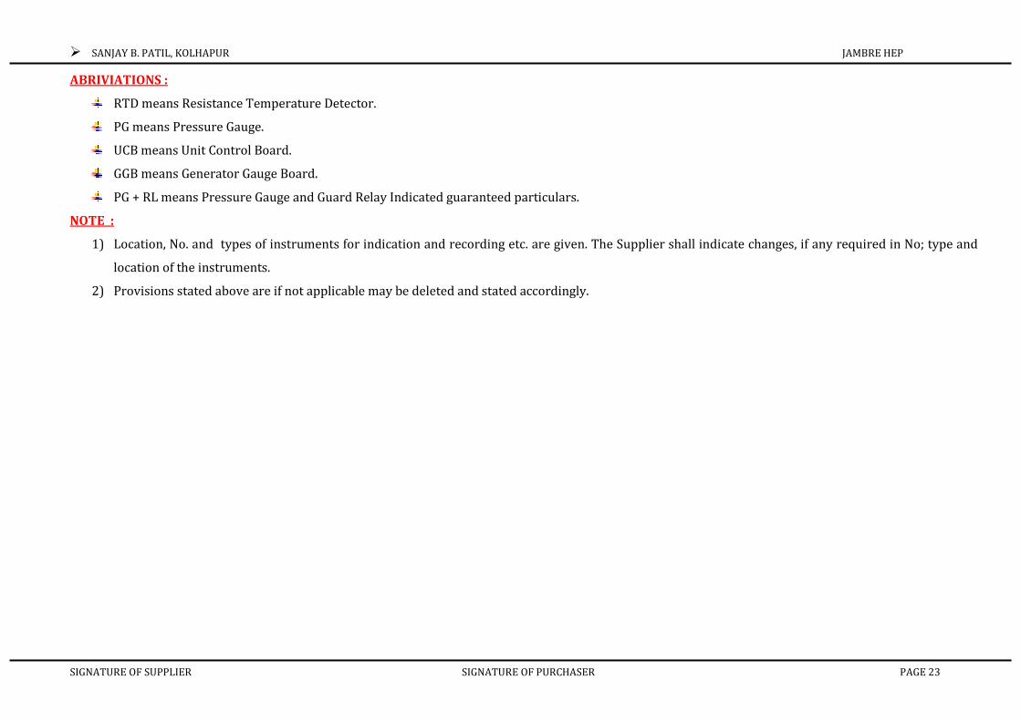
ABRIVIATIONS :
RTD means Resistance Temperature Detector.
PG means Pressure Gauge.
UCB means Unit Control Board.
GGB means Generator Gauge Board.
PG + RL means Pressure Gauge and Guard Relay Indicated guaranteed particulars.
NOTE :
1) Location, No. and types of instruments for indication and recording etc. are given. The Supplier shall indicate changes, if any required in No; type and
location of the instruments.
2) Provisions stated above are if not applicable may be deleted and stated accordingly.

SANJAY B. PATIL, KOLHAPUR JAMBRE HEP
SIGNATURE OF SUPPLIER SIGNATURE OF PURCHASER PAGE 24
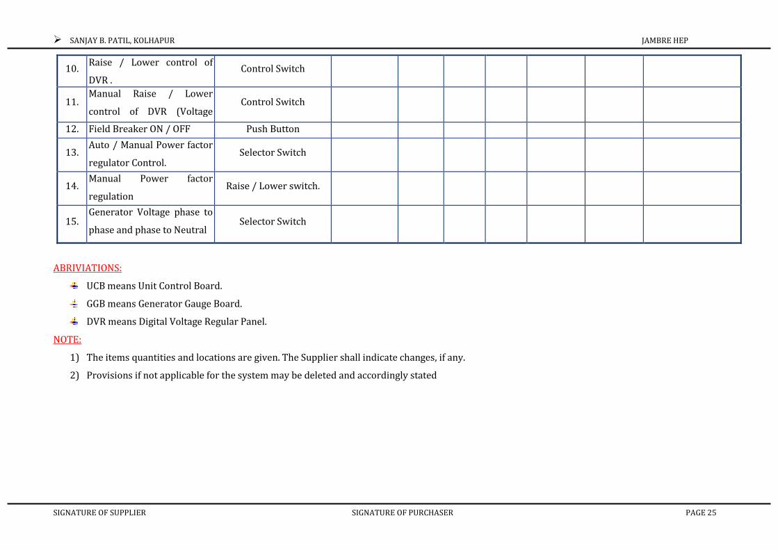
CONTROL INSTRUMENTS:
Sr.
No. Item indicated/recorded Type of device
Number provided
Remarks Locally or in
the vicinity
Unit Control Board At Mosaic
Board in
Control
room
Total At gen.
Gauge
panel
At DVR
or FSC
At unit
Control
Board
1 2 3 4 5 6 7 8 9
1. Auto-off-manual Selection
for generator heaters. Selector Switch
2. Auto / manual selection for
Generator brakes Selector Switch
3. Generator brake on/off
control. Emergency. BRAKE
'ON' system
Control Switch
4. H.P. Oil lubrication pump
starting / stopping. Push Button
5. Selection of location of H.P.
Oil 1 lubrication
pump/control 'Local /
Selector Switch
6. Auto / Manual Selection for
H.P. oil lubrication pump Selector Switch
7. Generator fire fighting
equipment control.
Push Button (Guarded
type)
8. Local / Remote control
Selection for excitation Selector Switch
9. Auto / Manual Selection for
excitation system.
Selector Switch
SANJAY B. PATIL, KOLHAPUR JAMBRE HEP
SIGNATURE OF SUPPLIER SIGNATURE OF PURCHASER PAGE 25
10. Raise / Lower control of
DVR . Control Switch
11. Manual Raise / Lower
control of DVR (Voltage Control Switch
12. Field Breaker ON / OFF Push Button
13. Auto / Manual Power factor
regulator Control. Selector Switch
14. Manual Power factor
regulation Raise / Lower switch.
15. Generator Voltage phase to
phase and phase to Neutral Selector Switch
ABRIVIATIONS:
UCB means Unit Control Board.
GGB means Generator Gauge Board.
DVR means Digital Voltage Regular Panel.
NOTE:
1) The items quantities and locations are given. The Supplier shall indicate changes, if any.
2) Provisions if not applicable for the system may be deleted and accordingly stated

SANJAY B. PATIL, KOLHAPUR JAMBRE HEP
SIGNATURE OF SUPPLIER SIGNATURE OF PURCHASER PAGE 26
SAFETY DEVICE UNDER THIS ANNEXURE SHALL BE DISCUSSED DURING DESIGN STAGE IN ACCORDANCE WITH UNIT CONTROL BOARD DESIGN.
TABLE III : SAFETY FOR EACH GENERATOR AND ASSOCIATIATED EQUIPMENT
Sr. No. Description of Abnormality Sensing device Alarm/Annunciation at Remarks
Type Quantity Unit Control
Board
At Mosaic
Board in
Control Room
1. HIGH TEMPERATURE OF
Rotor
• Temperature
Indicator
Guide bearing pads NDS • RTD
Thrust bearing pads • RTD
Guide bearing pads DS. • RTD
Thrust and guide bearing oil. • RTD
Air cooler inlet air • RTD
Air cooler cutlet air. • RTD
Stator winding • RTD *
Temperature
Stator teeth • Indicator RTO
Stator Core.
• RTD 1
temperature
Indicator
SANJAY B. PATIL, KOLHAPUR JAMBRE HEP
SIGNATURE OF SUPPLIER SIGNATURE OF PURCHASER PAGE 27
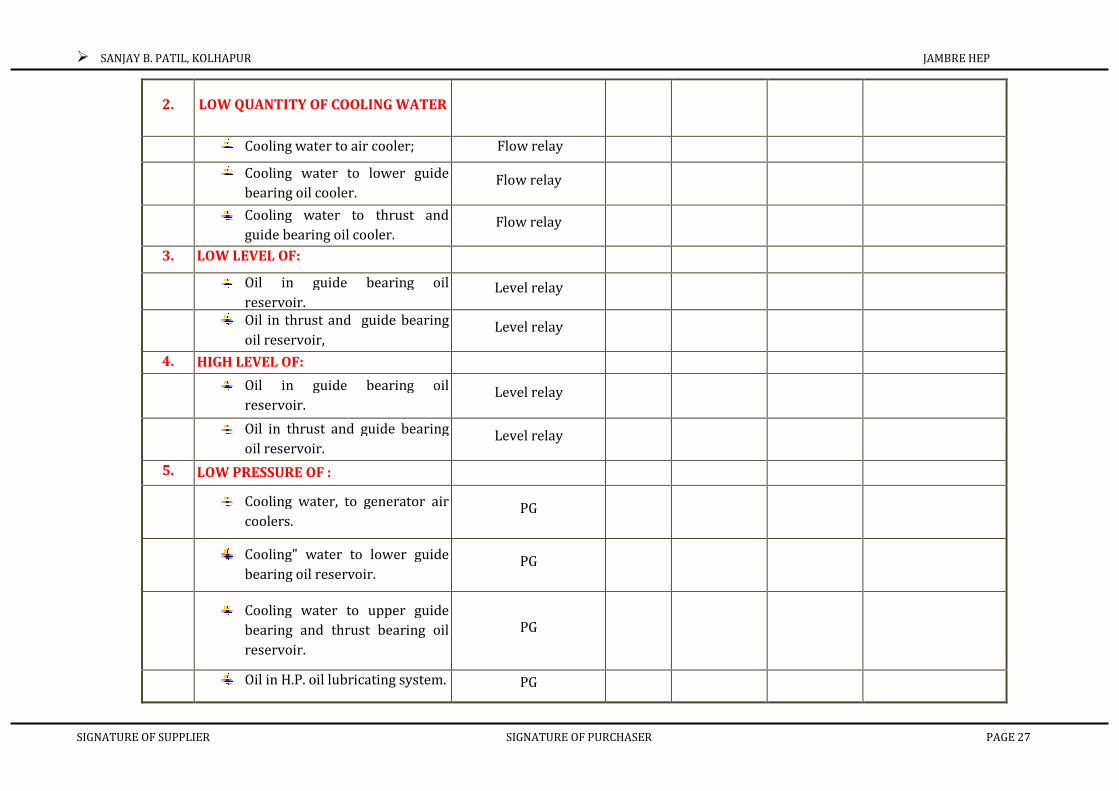
2. LOW QUANTITY OF COOLING WATER
Cooling water to air cooler; Flow relay
Cooling water to lower guide
bearing oil cooler. Flow relay
Cooling water to thrust and
guide bearing oil cooler. Flow relay
3. LOW LEVEL OF:
Oil in guide bearing oil
reservoir. Level relay
Oil in thrust and guide bearing
oil reservoir, Level relay
4. HIGH LEVEL OF:
Oil in guide bearing oil
reservoir. Level relay
Oil in thrust and guide bearing
oil reservoir. Level relay
5. LOW PRESSURE OF :
Cooling water, to generator air
coolers. PG
Cooling" water to lower guide
bearing oil reservoir. PG
Cooling water to upper guide
bearing and thrust bearing oil
reservoir.
PG
Oil in H.P. oil lubricating system. PG
SANJAY B. PATIL, KOLHAPUR JAMBRE HEP
SIGNATURE OF SUPPLIER SIGNATURE OF PURCHASER PAGE 28
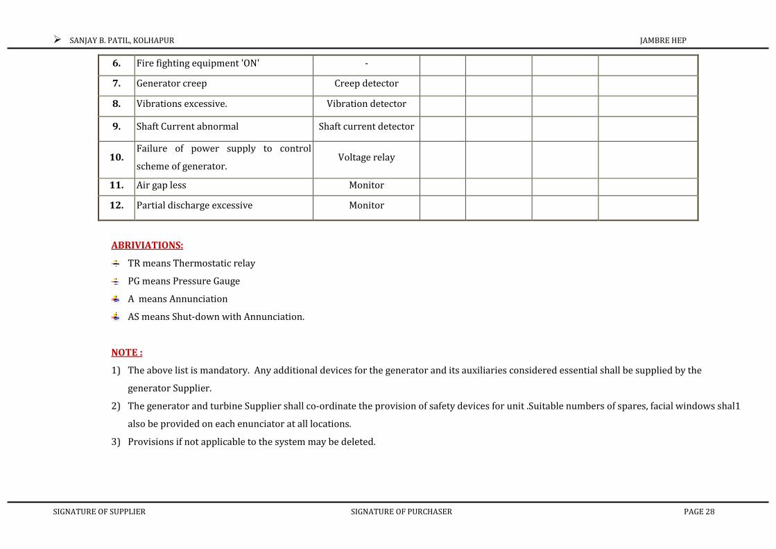
6. Fire fighting equipment 'ON' -
7. Generator creep Creep detector
8. Vibrations excessive. Vibration detector
9. Shaft Current abnormal Shaft current detector
10. Failure of power supply to control
scheme of generator. Voltage relay
11. Air gap less Monitor
12. Partial discharge excessive Monitor
ABRIVIATIONS:
TR means Thermostatic relay
PG means Pressure Gauge
A means Annunciation
AS means Shut-down with Annunciation.
NOTE :
1) The above list is mandatory. Any additional devices for the generator and its auxiliaries considered essential shall be supplied by the
generator Supplier.
2) The generator and turbine Supplier shall co-ordinate the provision of safety devices for unit .Suitable numbers of spares, facial windows shal1
also be provided on each enunciator at all locations.
3) Provisions if not applicable to the system may be deleted.
SANJAY B. PATILSANJAY B. PATILSANJAY B. PATILSANJAY B. PATIL
JAMBREJAMBREJAMBREJAMBRE HYDRO ELECTRIC PROJECTHYDRO ELECTRIC PROJECTHYDRO ELECTRIC PROJECTHYDRO ELECTRIC PROJECT
1 x 1 x 1 x 1 x 2020202000 KW00 KW00 KW00 KW
SECTION - II
DETAILED PRICE SCHEDULE

SANJAY B. PATIL, KOLHAPUR JAMBRE HEP
SIGNATURE OF SUPPLIER SIGNATURE OF PURCHASER PAGE 29
SECTION - II PRICE SCHEDULE (Amount in Indian Rupees.)
SR.NO
DESCRIPTION QTY. UNIT EXW UNIT PRICE
EXW TOTAL PRICE
TRANSPORT INSTALLATION
SERVICES & O& M.
INSURANCE
TOTAL
1.0 TURBINE & GENERATOR PLANT
1.1 Turbine:-HORIZONTAL FRANCIS
TURBINE of rated output 2000 KW+10% for 27 meter design Head compressed air system,
Cooling water system, Drainage and dewatering system, H.M.C., servomotor, oil and Water piping, valves, strainer, bends, flow meter relay etc. complete.
Mandatory Spares. Tools and Tackles.
1 Sets
1.2 Main Inlet Valve:- Butterfly type valve of
suitable dia. For suitable for connection
1800mm ID Penstock Along with
Bye pass valves , drain valves , man holes , inlet pipe, outlet pipe, dismantling joint, servomotor,
O. P. U. Control cabinet etc. complete.
Mandatory Spares. Tools and Tackles.
1 Sets
1.3 Gear Box if required
Mandatory Spares. Tools and Tackles. 1 no

SANJAY B. PATIL, KOLHAPUR JAMBRE HEP
SIGNATURE OF SUPPLIER SIGNATURE OF PURCHASER PAGE 30
1.4 Hydro Generator:- Horizontal shaft
synchronous alternator of 3.3 KV three
phase , 50 HZs, 2310 KVA at 0.866 p.f.
Brushless excitation system. complete,
with
H.S. Lubrication system, ,
Brake/ jack system, Fly Wheel stator
encloser, railing & coverings, coolers,
heaters, etc. complete.
Mandatory Spares. Tools and Tackles.
1 Sets
2 3.3 KV Switchgear comprising control &
relay panels suitable for computerized
control system consisting of as per SLD
Mandatory Spares. Tools and Tackles.
2.1 3.3 KV VCB Circuit breaker cubicle
Mandatory Spares. Tools and Tackles. 2 No.
2.2 3.3 KV cubicle for P.T. WITH Draw out Type P.T. 2 Core 3.3 KV/√3,110 V/√3,110 V/√3 , ht FUSE etc. Mandatory Spares. Tools and Tackles.
1 No.
2.3 3.3 KV CT having suitable current ratio with 4 core for protection & metering etc. Mandatory Spares. Tools and Tackles.
2 Sets Sets
SANJAY B. PATIL, KOLHAPUR JAMBRE HEP
SIGNATURE OF SUPPLIER SIGNATURE OF PURCHASER PAGE 31
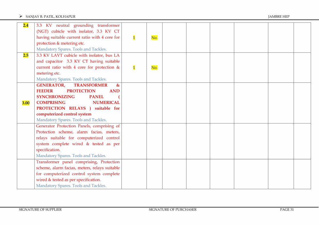
2.4 3.3 KV neutral grounding transformer (NGT) cubicle with isolator, 3.3 KV CT having suitable current ratio with 4 core for protection & metering etc. Mandatory Spares. Tools and Tackles.
1 No.
2.5 3.3 KV LAVT cubicle with isolator, bus LA and capacitor 3.3 KV CT having suitable current ratio with 4 core for protection & metering etc. Mandatory Spares. Tools and Tackles.
1 No.
3.00
GENERATOR, TRANSFORMER &
FEEDER PROTECTION AND
SYNCHRONIZING PANEL (
COMPRISING NUMERICAL
PROTECTION RELAYS ) suitable for
computerized control system
Mandatory Spares. Tools and Tackles.
Generator Protection Panels, comprising of Protection scheme, alarm facias, meters, relays suitable for computerized control system complete wired & tested as per specification. Mandatory Spares. Tools and Tackles.
Transformer panel comprising, Protection scheme, alarm facias, meters, relays suitable for computerized control system complete wired & tested as per specification. Mandatory Spares. Tools and Tackles.

SANJAY B. PATIL, KOLHAPUR JAMBRE HEP
SIGNATURE OF SUPPLIER SIGNATURE OF PURCHASER PAGE 32
Line protection cubicles for 33 KV lines comprising protection scheme, alarm facia, meters, relays suitable for computerized control complete wired & tested as per specification. Mandatory Spares. Tools and Tackles.
Synchronizing system comprising, protection scheme, alarm facias, meters, relays suitable for computerized control system complete wired & tested as per specification. Mandatory Spares. Tools and Tackles.
Unit control board for unit operation in auto , manual and remote mode. Mandatory Spares. Tools and Tackles.
4.0 REMOTE CONTROL SYSTEM Complete in all respect Including INTERFACES, and other material etc required for achieving total control of the plant in two levels(Local And Remote) of control with complete PLCC equipt suitable to the one installed by M.S.E.B. at receiving sub-station. Mandatory Spares. Tools and Tackles.
1
Set

SANJAY B. PATIL, KOLHAPUR JAMBRE HEP
SIGNATURE OF SUPPLIER SIGNATURE OF PURCHASER PAGE 33
5.0 POWER TRANSFORMER
Power Transformer of capacity 2.5 MVA, 3
Ph., 33 kV/ 3.3 KV , 50 Hz., ONAN type
with “ON” load tap changer, RTCC cubical
suitable for power cable connections on HT
and L.T. side with first filling of oil &
accessories.
Mandatory Spares. Tools and Tackles.
1 No.
6.0 33 kV INDOOR SWITCHGEAR
EQUIPMENTS 1 No
33 KV draw out type Switchgear with
control and protection system ,( as per SLD.
)suitable for computerized control system
2 NOS -33 KV VCB DRAWOUT , Circuit breaker cubicle AS PER specification.
1 SET
1 NOS.-33 KV cubicle for P.T. WITH Draw out Type P.T. 2 Core 33 KV/√3,110 V/√3,110 V/√3, ht FUSE etc.
1 SET -33 KV CT having suitable current ratio with 4 core for protection & metering etc. 1set
1 no- 33 KV rated insulation class BIL,170 KV Peak,50 A, 25 KA,3 Ph.,50 Hz, double break center pole rotating , Motorized outdoor isolator earth blades.
1 no

SANJAY B. PATIL, KOLHAPUR JAMBRE HEP
SIGNATURE OF SUPPLIER SIGNATURE OF PURCHASER PAGE 34
Supply of Metering Kiosk / outdoor CT and PT as per MSEDCL direction/ specifications.
1 set
Marshaling box Adequate No.s
Junction Boxes for C.T. and P.T. Adequate
Mandatory Spares, Tools & Tackles. 1 Set
7.0 415 V A.C. SWITCHGEAR PANEL
Indoor type 415 V, A.C. Distribution board
Panel comprising of two Nos., of incoming
A.C.B., including manual/ auto change over
for U.A.T. to D.G. Set A.C. supply’
Mandatory Spares, Tools and Tackles.
1 Set
8.0 110 VOLT D.C. EQUIPMENTS
Dry cell Batteries having capacity of 110 V/
300 AH Battery charger suitable for above
with float & float cum boost charger D.C,
Distribution Board with 20 Nos., of outgoing
feeders with accessories.
Mandatory Spares, Tools & Tackles.
1 Set

SANJAY B. PATIL, KOLHAPUR JAMBRE HEP
SIGNATURE OF SUPPLIER SIGNATURE OF PURCHASER PAGE 35
9.0 UNIT AUXILIARY TRANSFORMER
Unit Auxiliary Transformer 100 KVA, 33 KV / 415 V, 3 Phase, 50 Hz., outdoor type Suitable for 33 KV cable termination. Mandatory Spares, Tools & Tackles.
1 No.
10.0 POWER AND CONTROL CABLES
3.3 KV H.T. Power Cables single core 350 Sq. mm ,XLPE insulated ,copper, 5 kV (E) Grade, armored
33 KV H.T. Power Cables 3 core 185 Sq. mm ,XLPE insulated copper, armored .
L.T. Power & Controls Cables, copper, Screened Cables,
Trays, Racking, Trench Covers and suitable clamps for fixing cable trays with accessories etc. complete. Mandatory Spares, Tools & Tackles.
lot Set
11.0 OTHER ITEMS
11.1
E.O.T. Crane , (capacity, to be decided by bidder, 1 for Main and 1 for Auxiliary,) pendent operated , A.C., 415 V ± 10%, 3 Phase, 50 Hz., with down shop leads etc. ,complete. Mandatory Spares, Tools & Tackles for above items.
1 No

SANJAY B. PATIL, KOLHAPUR JAMBRE HEP
SIGNATURE OF SUPPLIER SIGNATURE OF PURCHASER PAGE 36
11.2
63 KVA, D.G. Set, 415 V, 3 Phase out door type , silent. Mandatory Spares, Tools & Tackles for above items.
1 No
11.3 Power House and Switchyard Earthmats , earth grid , And lightening protection.
Lot Lot
11.4 Power House & Switchyard lighting & Construction power supply.
Lot Lot
11.5 Fire Fighting Equipments, Rubber mat etc. Mandatory Spares, Tools & Tackles for above items.
Set Set
11.6 Communication System and furniture. Mandatory Spares, Tools & Tackles for above items.
Lot Lot
11.7 Workshop Equipments Mandatory Spares, Tools & Tackles for above items.
Set Set
11.8 Air Conditioning for control room Mandatory Spares, Tools & Tackles for above items.
Lot Lot
12.0 TRAINING AND INSPECTION
12.1 Training for Purchaser’s Engineer
12.2 Inspection at Works by Purchaser’s
Engineers
12.3 Factory Inspector & Electrical Inspector Inspection Clearance of pollution board and all other clearances.

SANJAY B. PATIL, KOLHAPUR JAMBRE HEP
SIGNATURE OF SUPPLIER SIGNATURE OF PURCHASER PAGE 37
Providing competent Engineers and other Skilled/ Unskilled/ Semiskilled workers, consumables and maintenance spares for operation and maintenance for Six (6) months period for JAMBRE H.E.P. ( 1 x 2000 KW) after commissioning of the unit for commercial use for SBP, KOLHAPUR
1 SET
13 Supply of mandatory tools and spares as per list attached in annexure I & II 1 LOT
GRAND TOTAL (1 TO 13)
14 TAXES AND DUTIES
A SUPPLY
a Excise Duty
b Sales Tax
c VAT or any other taxation
B Service Tax on Transportation
E Service Tax on O&M
F Erection & commissioning
a Service Tax
TOTAL - TAXES & DUTIES
GRAND TOTAL OF BID PRICE
INCLUDING TAXES & DUTIES
SANJAY B. PATIL, KOLHAPUR JAMBRE HEP
SIGNATURE OF SUPPLIER SIGNATURE OF PURCHASER PAGE 38
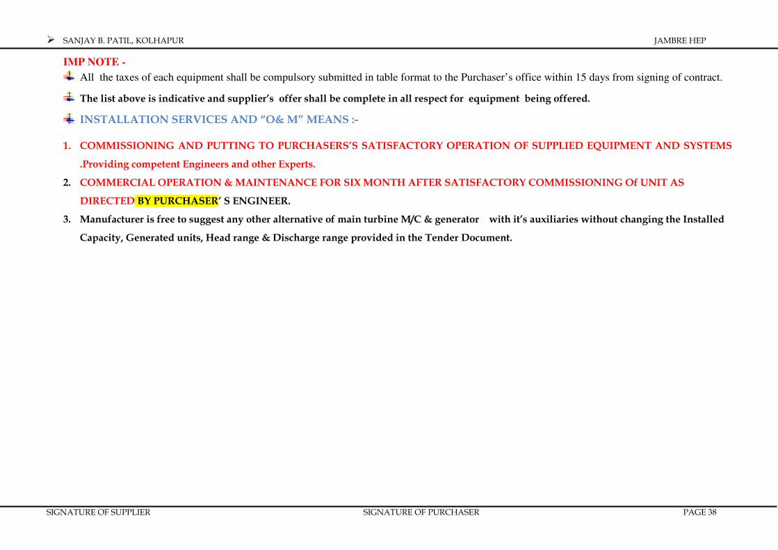
IMP NOTE -
All the taxes of each equipment shall be compulsory submitted in table format to the Purchaser’s office within 15 days from signing of contract.
The list above is indicative and supplier’s offer shall be complete in all respect for equipment being offered.
INSTALLATION SERVICES AND “O& M” MEANS :-
1. COMMISSIONING AND PUTTING TO PURCHASERS’S SATISFACTORY OPERATION OF SUPPLIED EQUIPMENT AND SYSTEMS
.Providing competent Engineers and other Experts.
2. COMMERCIAL OPERATION & MAINTENANCE FOR SIX MONTH AFTER SATISFACTORY COMMISSIONING Of UNIT AS
DIRECTED BY PURCHASER’ S ENGINEER.
3. Manufacturer is free to suggest any other alternative of main turbine M/C & generator with it’s auxiliaries without changing the Installed
Capacity, Generated units, Head range & Discharge range provided in the Tender Document.

SANJAY B. PATILSANJAY B. PATILSANJAY B. PATILSANJAY B. PATIL....
JAMBREJAMBREJAMBREJAMBRE HYDRO ELECTRIC PROJECTHYDRO ELECTRIC PROJECTHYDRO ELECTRIC PROJECTHYDRO ELECTRIC PROJECT
1 x 1 x 1 x 1 x 2020202000 KW00 KW00 KW00 KW
SECTION - IIA
PRICE SCHEDULE WITH BREAK UP

SANJAY B. PATIL, KOLHAPUR JAMBRE HEP
SIGNATURE OF SUPPLIER SIGNATURE OF PURCHASER PAGE 39
SECTION – II-A
DETAILED BREAK UP OF PRICE SCHEDULE OF MAIN PLANT & RELATED TO IT’S ALL MANDATORY SPARES
TO BE RECOMMENDED BY BIDDER Amount in Indian Rupees
Sr.
No. Description Qty.
Make & Country of
origin
Unit rates
Total Excise duty
VAT All
types of Taxes
Transport, Insurance, loading & unloading
Ex-factory
01 02 03 04 05 06 07 08 09 10
MAIN TURBINE AND GENERATOR
PLANT AND ITS ASSOCIATD
EQUIPMENT OR ALL TYPRS OF
MANDOTARY SPARES
1 TURBINE EQUIPMENT 1 Set
2 FOR GOVERNOR AND OIL PRESSURE SYSTEM
1 Set
3 HYDRO MECHANICAL CABINET 1 Set
4 MAIN INLET VALVE 1 No.
5 COMPRESSED AIR SYSTEMS. 1 set If Required or otherwise.
1 Set
6 COOLING WATER SYSTEM. lot Standard spares for pumps & motors.
2 Sets.
7 GENERATOR 1 No.
8 STATC EXCITATION SYSTEM. 1 Set
8a SPARE FOR FIELD BREAKER.
8b SPARES FOR FIELD FLASHING CONTACTOR
9 3.3 KV SWITCHGEAR. Lot
10 GENERATOR, TRANSFORMER, FEEDER SYNCHRONISING PANEL.
Lot

SANJAY B. PATIL, KOLHAPUR JAMBRE HEP
SIGNATURE OF SUPPLIER SIGNATURE OF PURCHASER PAGE 40
lot
11 REMOTE CONTROLL SYSTEM. 1 Set
12 E.O.T. Crane. 1 No.
13 Power Transformer 3.0 MVA. 1 No.
14 Auxiliary Transformer 100 KVA. 1 No.
15 D.G. Set. 1 No.
16 A.C. System. Lot
17 D.C. System. 1 No.
18 Indoor Switchyard. Lot
19 Air Conditioning. Lot
20 Fire Fighting System. Lot
21 Fire Hydrant System. Lot
SEALED AND SIGNED BY SUPPLIER

SANJAY B. PATILSANJAY B. PATILSANJAY B. PATILSANJAY B. PATIL....
JAMBREJAMBREJAMBREJAMBRE HYDRO ELECTRIC PROJECTHYDRO ELECTRIC PROJECTHYDRO ELECTRIC PROJECTHYDRO ELECTRIC PROJECT
1 x 1 x 1 x 1 x 2020202000 KW00 KW00 KW00 KW
SECTION - III
TECHNICAL SPECIFICATIONS

SANJAY B. PATIL, KOLHAPUR JAMBRE HEP
SIGNATURE OF SUPPLIER SIGNATURE OF PURCHASER PAGE 41
SECTION – III - A
DETAIL TECHNICAL SPECIFICATION
MAIN TURBINE AND GENERATING PLANT AND ITS ASSOCIATED AUXILIRIES.
3.1 TURBINE:
3.1.1 The turbine called for under this specification is Horizontal Francis type moveable blades
with auxiliaries and all accessories required for its work at gross design head of 27 meter.
Tenderer shall calculate net heads based on parameters of the water conductor system actual
at site.
The turbine shall be suitable for following operating conditions.
a) The turbine shall be suitable for operating between the variable heads of about 33.50
meter to 17.40 meter. The design head shall be 27 m gross. Also, the turbine shall be
suitable for smooth operation at any discharge from minimum at 50% load at rated head
to maximum of about 9.33 m3/sec.
The rated output of turbine at rated head of 27 m is expected with a gate opening of
around 85 percent. It is desired that best efficiency of the turbine shall be obtainable at
the rated output of not less than 2000 KW with the discharge of 9.33 cumecs and the gate
opening of 85 %. The Contractor shall indicate in his tender the value of the best
efficiency of the turbine stating the output value with discharge and gate opening at
which it is obtainable.
b) The output of not less than 2200 kW at 10 % continuous over load at rated head condition
shall be obtainable with the gate opening value of around 93 percent. Besides, the
Contractor shall furnish in his tender, characteristics charts/performance curves,
tabulating therein the values of turbine outputs at gate opening of 25%, 50 %, 80 %, 90 %,
100%, and 110% for different heads from 17.40 to 33.50 m.
c) Turbine shall be suitable for trouble free continuous operations at 110% of rated
load and shall be accordingly guaranteed. The turbine shall be suitable for smooth
operating under such conditions.
3.1.2 STRESSES AND FACTOR OF SAFETY :
All parts of turbine shall be designed and constructed to safely withstand the maximum
stresses during the normal running and runaway and short circuit conditions, out of phase
synchronizing and erratic brake applications. The maximum unit stresses of the rotating
parts shall not exceed two third of the yield point of the material. For other parts, the factor
of safety based on yield point shall not be less than 3 at normal conditions. For overload and
short circuit conditions, factor of safety of 1.5 on yield point shall be permitted.
3.1.3 SPEEDRISE AND RUNAWAY SPEED :

SANJAY B. PATIL, KOLHAPUR JAMBRE HEP
SIGNATURE OF SUPPLIER SIGNATURE OF PURCHASER PAGE 42
The moment of inertia of the unit and the normal wicket gate closing time shall be so adjusted
that the maximum momentary speed rise of the unit shall not exceed 50% and the maximum
pressure rise in the penstock shall not exceed 25% of the maximum static head under any
condition of operation. The turbine manufacturer shall co-ordinate with the generator
manufacturer for limiting the speed and pressure rise values and accordingly design fly-
wheel. The maximum runaway speed of the unit under any combination of head and load
conditions shall be stated in the tender. The turbine shall be capable of running safely at
maximum runaway speed without any damage to its parts for a period of not less than 15 (
fifteen ) minutes for every such occurrence with cooling water supply on and 5 minutes with
interruptions of cooling water during such occurrence. If required pressure relief valve shall
be put into the system to arrest pressure rise to protect long water conductor system.
3.1.4 STANDARDS
IEC 60041 --International code for Field Acceptance Tests of Hydraulic Turbines
IEC 60308-- International code for testing of speed governing systems for hydraulic turbines
IEC 60545-- Guide for commissioning, operation & maintenance of hydraulic turbine
IEC 60994-- Guide for field measurement of vibrations and pulsations of hydraulic machines
IEC 60995-- Determination of prototype performance from model acceptance test of hydraulic
machines with consideration of scale effects
IEC 60193-- International standard – Hydraulic turbines - Model acceptance tests
IEC 60041-- International standard field acceptance tests of hydraulic turbines
IEC 60609 P 1--Cavitations pitting evaluation in hydraulic turbines, storage turbines and
pump-turbines, Part 1.
ASME Boiler and Pressure Vessel Code, Section VIII
IS 12800--Guidelines for Selection of Turbines, Preliminary dimensioning and layout of
Surface Hydro Electric Power house
IS : 1271--Classification of insulating materials for electrical machinery
IS : 2379--Colour code for the identification of pipelines
IS : 5-- Colour for ready mixed paints and enamels
IS : 226--Structural steel (standard quality) (fifth revision)
IS : 1538--Cast Iron fittings for pressure pipe for water, gas and sewage
IS : 6392--Steel pipe flange
IS : 2906--Sluice valves for water works
IS : 2002--Medium tensile steel plate used for welding, flame cutting and flanging in hot
condition
IS : 2049--Colour code for identification for wrought steel for general engineering purposes
IS : 1030--Cast steel

SANJAY B. PATIL, KOLHAPUR JAMBRE HEP
SIGNATURE OF SUPPLIER SIGNATURE OF PURCHASER PAGE 43
IS : 28 -- Bronze
IS : 1239--G.I. pipes Part 1, Part 2
Note: The latest edition of the above codes shall be referred.
3.1.5 GENERAL ARRANGEMENT AND CONSTRUCTION
The turbines shall be installed in a setting as indicated in the layout drawing or setting
indicated by supplier and approved by purchaser. The generator, flywheel etc. shall be
mounted on a suitable chassis/platform mounted over the turbine floor. The design shall be
such that so as to enable easy assembly and erection at site and the spacing of the equipment
should be sufficient for maintenance of turbine and generator. The statement of origin of
materials shall be confirmed in the bid. The certificate of origin must be handed over when
materials are in workshop. In the bid all sub-suppliers must be named and be approved by
the Purchaser/Client.
3.1.6 GUIDE VANES
The number of guide vanes selected shall be well matched to ensure turbine operation
without objectionable vibration. The guide vanes shall be shaped to permit smooth flow of
water through the turbine and shall be so proportioned as to maintain closing tendency
under any normal operating conditions of the turbine.
The turbine Guide Vanes and stems shall be of die cast 13-4 Cr-Ni stainless steel. Each gate
shall be machined smooth and ground to an accurate form and finish.
Each Guide Vane shall be provided with greaseless self lubricating bush type guide bearings.
Each stems shall be provided with a thrust bearing of bronze to carry the weight of the guide
vane and withstand hydrostatic thrust. Convenient means shall be provided for adjusting
and maintaining the clearances of the Guide Vanes.
The Guide Vane operating mechanism shall be of ample strength to withstand the most
severe operating conditions. All working points with relative motion shall be bronze bushed
and provisions for grease lubrication. Means shall be provided for adjusting the position of
any individual Guide Vane independently.
Each Guide Vane shall be individually connected to the Guide Vane operating ring through a
set of lever and links.
Suitable shear pin shall be provided between each Guide Vane stem and Guide Vane
operating ring which shall be strong enough to withstand the maximum normal operating
forces but will break or yield due to forces in opening or closing direction and will protect the
rest of the mechanism from damage when one or more of the Guide Vanes become jammed.
A shear pin failure check circuit shall be provided which shall be electrically continuous if all

SANJAY B. PATIL, KOLHAPUR JAMBRE HEP
SIGNATURE OF SUPPLIER SIGNATURE OF PURCHASER PAGE 44
pins are sound. If any one pin is sheared it shall furnish annunciation in the unit control
board. A shear pin break test shall be performed in the shop.
Solid stops and suitably designed friction device shall be provided for each Guide Vane to
limit the angle and rate of movement of Guide Vane stem levers while opening and closing
on shear pin failure. The loose Guide Vane and its linkage after shear pin failure shall not
interfere with the operation of other Guide Vane or turbine parts or cause progressive failure
of adjacent shear pins.
Seals shall be provided above and below Guide Vanes to effectively reduce leakage of water
or air. Segmented seals of proven design shall be used.
3.2 GUIDE VANES REGULATOR
The guide vanes arrangement must be provided with closing tendency when not operated by
power pack. The guide vanes shall be operated by one number of double-acting oil pressure
operated, fabricated or cast steel servomotor having adequate capacity to operate the turbine
Guide Vanes to full opening or closing stroke under all conditions. The servomotor shall be
capable of moving the guide vanes smoothly during full opening and closing in required time
as per pressure rise and speed rise limits given in the bid.
The servomotor shall be provided with suitable adjustable bypass connections for cushioning
to achieve retardation in the rate of closure during the portion of Guide Vane travel from
slightly below speed-no-load position to the fully closed position to prevent excessive
pressure changes in the water passages.
Manual locking devices to hold the guide vanes in the closed or open position against
maximum oil pressure shall be provided. Switches for interlocking circuits and lamp
indication of the locking device position shall be provided on local panel and on unit control
board.
Provision for connecting the restoring cable from the actuator on the piston rod of servomotor
shall be provided. A scale calibrated in tenths of Guide Vane position shall be rigidly
attached to servomotor position by means of a pointer.
3.3 RUNNER
The runner shall be Kaplan type confirming to IEEE – 810 (1987). The runner and runner
blade material shall be DIN 17.445, Material Nr 1.4113, G-X5 CrNi 13.4,ASTM A 743 CA 6
NM, The runner shall be die forged in one piece with integral labyrinths and shall be
designed to provide the best hydraulic profile so that it gives the maximum efficiency with
minimum cavitation. The composition of the material and the source of runner casting shall
be stated in the Bid. The blades of the runner including the spare shall be interchangeable. A
bolted connection shall be provided for attaching the runner to the turbine shaft. Opening
shall be provided through the runner crown to drain the water and reduce the hydraulic

SANJAY B. PATIL, KOLHAPUR JAMBRE HEP
SIGNATURE OF SUPPLIER SIGNATURE OF PURCHASER PAGE 45
thrust. It shall be housed with bearing bushes to withstand safely all forces during operation
as well as during max. Runaway speed. Runner blades shall be suitable for operation through
runner blade governing system, hydro-mechanical cabinet.
The runner with assembled blades and blade angle changing mechanism shall be statically /
dynamically balanced in the works and so designed so as to safely withstand loading due to
normal and abnormal operating conditions including effects of blade thickness reduction due
to cavitation erosion, introduction of stress due to on site welding of damaged blades,
increased pressures at transient conditions and discharge related to maximal guide vane
opening and runner blade opening. The runner shall be designed to withstand stresses due to
resonant vibrations. The Contractor shall clearly present his calculation criteria with respect
to maximal possible stresses in the runner parts including blades, related to mechanical
properties of the runner material.
The runner shall be free from internal stresses and casting imperfections. All surfaces of the
runner exposed to the flow of water shall be carefully machined and finished smooth to
templates. There shall be no hollows, depressions, waviness, projections and/or other surface
imperfections that might lead to local disturbance, erosions and/or cavitation. Other highly
stressed areas of the runner shall be finished smooth to judge the quality of the casting or
forging and evaluate possible material defects.
The conformity of the blade shape to the design drawings shall be verified by use of
templates or other shop control devices. Templates for guidance in restoring blade and
bucket shapes to original contour shall be supplied with the runners. The method for blade,
hub and runner removal shall be clearly specified. The special tools and tackle required for
dismantling and fixing of runner shall be supplied.
Alternatively, the supplier may propose a runner of fabricated construction in accordance
with modern fabrication practice as long as the runner meets the requirements of efficiency
and minimum cavitation.
3.4 SHAFT AND COUPLING
The turbine shaft (if required) shall be of hollow centrally bored for runner blade mechanism
and of forged carbon steel or alloy steel conforming to ASTM A 668 Class D or equivalent
standards. Wherever the flanges are integral with the shaft, the same should conform to
International Standard. The turbine shaft shall be connected to the runner on one side and to
the flywheel on the other side. It shall be of ample size to transmit torque at rated speed
without any vibration or any distortion. The main bearing concept of runner must be
provided in drawings with tender documents. The couple shall be elastic one for operational
comfort.

SANJAY B. PATIL, KOLHAPUR JAMBRE HEP
SIGNATURE OF SUPPLIER SIGNATURE OF PURCHASER PAGE 46
A renewable and removable sleeve of stainless steel shall be provided wherever the shaft
passes through a shaft seal or a gland. The sleeve shall be of corrosion-resisting material,
accurately machined, polished, and adequately secured to the shaft. The detail of sealing
must be provided in the bid document. (However runner directlyco0upledon on the generator shaft
shall be preferred)
3.5 BEARINGS
The turbine bearing (if the turbine shaft is provided) shall be pedestal mounted journal type
oil lubricated thrust cum guide bearing. The turbine shall be provided with adequate
number of bearings. The bearings shall be designed to withstand operation at maximum
runaway conditions without cooling water supply (if cooling water is provided) or
lubrication system for a period of not less than 15 minutes and also for operation at normal
speed without cooling water supply for 15 minutes. The bearings shall be provided with a
dial type and resistance type thermometer, a pressure gauge together with provision for
alarm annunciation / shut-down on excessive bearing temperatures and sight level gauges,
valves and piping for cooling water. The bearing temperature should not exceed 55°C under
any operating conditions. The number and type of bearings shall be stated in the bid. Type of
lubrication system provided shall be clearly indicated in the bid. The bidder may also offer
with self lubricating bearing water cooled bearings confirming to the above stated
requirements.
3.6 SHAFT GLAND
The shaft gland shall be of the stuffing box / carbon ring type with self lubricated packing
and lantern ring. Any other suitable type of shaft gland will also be considered. The gland
shall effectively prevent leakage of water along the shaft under all operating conditions and
at standstill and prevent entry of air. Details for starting and operation of the turbine and
shut-off action shall be particularly provided for in the bid. In case the location of the gland is
below maximum tail water level, an inflatable rubber seal shall be provided for attending the
main gland without dewatering the draft tube. A stainless steel sleeve with self-lubricating
type shall be provided on the shaft where it passes through the gland.
Arrangement for providing cooling water supply to the gland, if required, shall be made by
the Bidder and indicated in his Bid drawings.
3.7 S- TYPE RUNNER CHAMBER , DRAFT TUBE CASING AND STAY RING
The s-type runner chamber, draft tube and stay ring enclosure casing with runner chamber
support, side cover support etc. shall be constructed in accordance with best design practice
so as to provide efficient operation of turbine. A set of stay vanes of appropriate construction

SANJAY B. PATIL, KOLHAPUR JAMBRE HEP
SIGNATURE OF SUPPLIER SIGNATURE OF PURCHASER PAGE 47
of steel shall be provided with inside material 13:4 Cr.Ni.. The chamber shall be provided
with an air release cum anti-vaccum valve for evacuation of air.
The casing shall be fabricated from welded steel plate / mild steel plates and shall have
suitable sections for ease of shipment and to be within transport limitation. The case and
stay ring shall be designed to withstand maximum water pressure including water hammer
and shall be complete in all respects with anchors, supports, sole plates, turn buckles, hold-
down rods, all types of clamps etc. The turbine should not communicate vibrations to the
building nor any other dynamic load to be burdened.
The stay-ring shall be of cast steel or fabricated from welded steel plate and suitably stress
relieved prior to machining. Flanges shall be provided for bolted connections between the
stay ring and the side cover, and between the stay ring and the discharge ring. Alternatively
the discharge ring may be welded to the stay ring prior to stress relieving and machining.
The stay ring shall be designed to support the weight of the superimposed structures and
parts, with casing empty, and to withstand safely the forces due to maximum head, including
maximum pressure rise. For fabricated stay ring designs, the stay vanes shall protrude
through the upper and lower shroud plates and shall be shop-welded with full penetration
welds. Fabrication of the stay ring in the field will not be allowed.
3.8 SIDE COVER
The side cover shall be of cast steel or welded plate construction suitably sectionalized for
ease of transportation. Suitable replaceable labyrinth rings or similar sealing arrangements
shall be provided. The Supplier must detail the concept of sealing. The side cover shall be
designed and constructed to support all necessary seals, bearings, guide vanes assemblies,
etc. The setting of the cover and the adjustment of all relevant parts during commissioning
must be clearly described by the Bidder in his offer.
3.8.1 TURBINE FRAME, PLATFORM, WALKWAYS, HANDRAILS ETC.
A support frame on which to mount the case, bearing pedestals, generator, brakes, and
exciter shall be supplied as part of this specification and detailed in the Bid document.
3.8.2 GOVERNING EQUIPMENT
Turbine shall be equipped with suitable dedicated electronic governor conforming to IEC No.
60308. The governor shall be of proven design capable of maintaining control of speed under
all conditions of head and load in a stable manner when operating in solo or grid operating in
parallel with other generating units in the grid. Such governing system shall be complete
with actuator unit comprising speed responsive element, restoring mechanism having
adjustable temporary and permanent droop setting, load limiting device, speed level control
etc.

SANJAY B. PATIL, KOLHAPUR JAMBRE HEP
SIGNATURE OF SUPPLIER SIGNATURE OF PURCHASER PAGE 48
The speed responsive element of the governor shall be operated by a toothed wheel mounted
on the generating unit shaft with speed pick-ups or its equivalent that shall be normally used
as an input to the speed-sensing device. Standard protections like over speed device, brake
control, emergency shut down and alarms etc., shall be provided in the governing systems.
Turbine governor shall be of latest design and shall comprise of a digital electronic,
microprocessor based part for control and regulating function and a hydraulic part acting as a
power-amplifying servo unit.
The electronic part shall house all the electronic devices and circuitry of the governor viz.
microprocessor circuits, speed sensing transducer and circuits, amplifier circuits, feed back
loop circuits, parameters speed drop circuit, stabilizing circuits and other control for
adjustment of governor parameters.
A complete transfer function block diagram for the governor offered indicating the various
gains and time constants of different components, with their relationship shall be supplied
The hydraulic part shall house complete hydraulic mechanical equipment comprising of pilot
valves, auxiliary servomotor, main distributing valves, devices for, automatic shutdown,
emergency shutdown and adjustment of governor closing and opening times.
3.9 PRESSURE OIL SYSTEM
The pressure oil system shall cater to the governing system for unit and the Main Inlet
Butterfly Valve. Pressure oil system shall comprise of a separate pressure oil tank for both
generating unit and their respective Main Inlet Butterfly Valve. Two numbers of electrically
operated oil pumps will be provided, one for normal running and acting as standby.
Provision for emergency shut down of the unit without any oil pump running shall also be
made. Gauges, pressure switches etc. will be provided as may be necessary. The oil
pressuring system needs to be equipped with an oil retaining basin in case of any leakage.
3.10 NITROGEN ACCUMULATORS
Nitrogen accumulators of sufficient capacity shall be provided for maintaining the required
pressure in the system. The capacity of the accumulator should be suitable for at least one
closure of the Turbine and generator (if hydraulic brakes are provided).
3.11 OIL AND LUBRICANTS
The Contractor shall indicate the specification and quantity of the governor system oil and of
the bearing oil required for each turbine and shall supply sufficient oil for the first filling plus
10% extra of each type. Where possible, the specification for the governor oil and for the
bearing oil shall be the same.

SANJAY B. PATIL, KOLHAPUR JAMBRE HEP
SIGNATURE OF SUPPLIER SIGNATURE OF PURCHASER PAGE 49
3.12 DRAINAGE AND DEWATERING SYSTEM
DEWATERING SYSTEM
The dewatering system shall be designed for dewatering of scroll case and draft tube. Initially
the water shall be drained by gravity up to the prevailing tail water level and then the
remaining water, if any, shall be pumped to the tailrace by one portable, submergible pump,
installed in the sump provided for dewatering located in the powerhouse. The pump must be
complete with hoses, piping, and fittings etc. This pump will also be used for drainage
pump. The pump, hoses, pipe, and fittings shall be supplied by the Contractor. The capacity
of dewatering pumps shall be adequate to de-water each unit in reasonable time not
exceeding three hours.
DRAINAGE SYSTEM
The drainage system includes floor drains, leakage water drains, seepage water from all the
walls in contact of water, outside walls with backfill against them and drainage of water from
other equipment such as compressors, air conditioning plants, turbine shaft glands etc. All
the drains shall be connected through drainage header to the drainage sump located in
powerhouse.
3.13 CORROSION PROTECTION AND COATING
For all structural steel and cast iron parts including piping for areas in contact with air, oil
and water the following applies:
Surface Preparation : On all cast iron and structural steel parts the rust must be removed by
mechanical means sandblasting to obtain a bare surface as per international practice.
Prime Coat for all areas : 2 layers with "Friazinc R", dry thickness of each layer 40 microns.
Type A: Areas in contact with water: After assembling the mechanical parts in the workshop
of all items to be delivered three coats of water resistant paint must be applied with each
layer having a minimum thickness of 100 microns.
Type B: Areas in contact with oil: All those areas will receive three coats with oil resistant
paint, for example Keratol, which must be applied as finishing coat.
Type C: Areas in contact with air: All those areas still accessible after assembling on site,
receive two prime coats with different colors. The prime coat consists of a preliminary final
coat in blue for the turbine casing and red for all the moveable parts.
Areas in contact with concrete: Cast-in items do not receive any coating, but must be free of
rust and spunk.
Cast-in items exposed to air and water must be provided with a prime coat to a depth of
approximately 150 mm into the concrete.

SANJAY B. PATIL, KOLHAPUR JAMBRE HEP
SIGNATURE OF SUPPLIER SIGNATURE OF PURCHASER PAGE 50
Pipelines in contact with water: They must be provided with three coats of water resistant
paint.
Oil carrying pipelines: They must be dismantled after assembling on site, pickled in acid
solution, neutralized and oiled.
All bare surfaces, which are not in contact with oil, shall be provided with a protection coat
(removable with water) after manufacturing.
Parts located in inaccessible areas, which must not be dismantled after workshop assembling
must be protected as follows:
The electrical equipment such as electric motors, limit switches, control panels etc. must
receive corrosion protection according to specifications in the worst atmosphere.
The color coating will be determined by the client. Any coated surface damaged after or
during assembling must be reinstated.
3.14 SHOP ASSEMBLY AND WORKSHOP TESTS
3.14.1 GENERAL
Relevant IS & International standard recommendations for the selection of materials and
testing of plates, cast iron and forged items for hydroelectric power plants must be adhered
to. Samples of steel plates shall be tested by the Contractor. Metallurgical strength,
crystallographic, ultrasonic, and borescope shall be performed on the turbine shaft during
manufacture. The results of all tests shall be delivered to the Purchaser within one (1) month
after material has been tested
Cost of all tests required in the workshop as well as on site including provision of personnel
and equipment required to carry out these tests must be included in the offer.
The following assemblies and test shall be carried out on the turbines and associated
equipment at the manufacturer's works before dispatch in the presence of representative of
the Purchaser/Consultant, if desired by the Purchaser, and test certificate shall be submitted:
The turbine manufactured shall be assembled in the shop in the presence of purchaser .
Static and dynamic balancing of runners
Hydrostatic testing at 1.5 times the maximum static / working pressure including water
hammer for not less than 15 minutes for the casing, servomotor etc.
Non-destructive testing of weld joint and major castings and forgings.
Performance tests for individual auxiliary equipment
Complete assembly and simulation test of governors etc.,
All motors / pumps / compressors etc. shall be tested as per relevant Indian or other
international standards.

SANJAY B. PATIL, KOLHAPUR JAMBRE HEP
SIGNATURE OF SUPPLIER SIGNATURE OF PURCHASER PAGE 51
3.14.2 MANUFACTURING AND ERECTION OF EQUIPMENT
The design of the turbine with all the auxiliary equipment must comply with the
acknowledged technical standards. The unit must be free of vibrations with extreme low
noise level under all operating conditions. The respective requirements from the authorities
must be met. All design work required for manufacturing, delivery and erection upto
commissioning of all equipment parts are included in the Supplier's scope of work.
The Supplier guarantees that the assembly of the turbines will be carried out in an
appropriate and faultless manner. Suppliers shall delivery turbine and its auxiliaries in the
assembled condition to the maximum extend possible, subject to transport limitations if any..
3.15 PACKING AND TRANSPORT
All parts to be delivered must be packed in a proper manner and then loaded and
transported to site, unloaded and stored properly.
3.16 COMMISSIONING (TRIAL OPERATION), TEST RUN AND ACCEPTANCE TESTS
After completion of the erection and operational readiness checks of the plant, the
components supplied by the Contractor will be commissioned as part of the commissioning
of the generating unit and ancillary equipment as a whole. The commissioning will be
carried out under the direction of a Commissioning Coordinator. The commissioning will be
carried out as per a procedure approved by Purchaser. 90 days before the anticipated time of
commissioning the first unit, the Contractor shall submit to the Purchaser procedures for the
commissioning of his equipment which will be integrated into overall procedures for the unit.
3.16.1 COMMISSIONING TESTS (TRIAL OPERATIONS)
The Supplier shall carry out the trial operations / commissioning tests in accordance with IEC
545. The turbine and its auxiliaries shall be commissioned first and shall be free from
problems of leakages, over heating, failure, damage etc.
The commissioning period for each turbine is considered to be completed after the following
tests have been carried out successfully:
Minimum five start-ups and shutdowns,
The turbine with all the auxiliary equipment has been operating continuously over a
period of at least 72 hours. During the scheduled 72 hours of operation, the turbine
output may vary 40% to 110% of full load several times. The period of any shut down or
tripping of the machine or supplied auxiliaries due to fault of Bidder will further be
added to 72 hours.
After successful completion of the 72 hour test run, the machine shall be handed over &
the five year guarantee period comes into force.
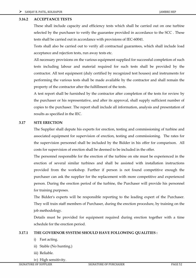
SANJAY B. PATIL, KOLHAPUR JAMBRE HEP
SIGNATURE OF SUPPLIER SIGNATURE OF PURCHASER PAGE 52
3.16.2 ACCEPTANCE TESTS
These shall include capacity and efficiency tests which shall be carried out on one turbine
selected by the purchaser to verify the guarantee provided in accordance to the SCC . These
tests shall be carried out in accordance with provisions of IEC-60041.
Tests shall also be carried out to verify all contractual guarantees, which shall include load
acceptance and rejection tests, run away tests etc.
All necessary provisions on the various equipment supplied for successful completion of such
tests including labour and material required for such tests shall be provided by the
contractor. All test equipment (duly certified by recognized test houses) and instruments for
performing the various tests shall be made available by the contractor and shall remain the
property of the contractor after the fulfillment of the tests.
A test report shall be furnished by the contractor after completion of the tests for review by
the purchaser or his representative, and after its approval, shall supply sufficient number of
copies to the purchaser. The report shall include all information, analysis and presentation of
results as specified in the IEC.
3.17 SITE ERECTION
The Supplier shall depute his experts for erection, testing and commissioning of turbine and
associated equipment for supervision of erection, testing and commissioning. The rates for
the supervision personnel shall be included by the Bidder in his offer for comparison. All
costs for supervision of erection shall be deemed to be included in the offer.
The personnel responsible for the erection of the turbine on site must be experienced in the
erection of several similar turbines and shall be assisted with installation instructions
provided from the workshop. Further if person is not found competitive enough the
purchaser can ask the supplier for the replacement with more competitive and experienced
person. During the erection period of the turbine, the Purchaser will provide his personnel
for training purposes.
The Bidder's experts will be responsible reporting to the leading expert of the Purchaser.
They will train staff members of Purchaser, during the erection procedure, by training on the
job methodology.
Details must be provided for equipment required during erection together with a time
schedule for the erection period.
3.17.1 THE GOVERNOR SYSTEM SHOULD HAVE FOLLOWING QUALITIES :
i) Fast acting.
ii) Stable (No hunting.)
iii) Reliable.
iv) High sensitivity.

SANJAY B. PATIL, KOLHAPUR JAMBRE HEP
SIGNATURE OF SUPPLIER SIGNATURE OF PURCHASER PAGE 53
v) Easy control.
The governing system shall be designed to allow operation of the unit ( i.e. turbine and
generator ). Further, the system should be suitable for operation of the unit in both ways
either in ‘Individual control’ or in ‘ Joint control of the units’.
The system shall be such as to ensure ‘bump less transfer’ when the control is switched from
‘Individual control’ to ‘Joint control’ and vice versa at any load. Besides provision shall be
made to share the load equally when the units are placed in ‘ Joint control’.
The governing system shall be designed to perform the following functions.
1) Unit start-up.
2) Idling and synchronization.
3) Parallel operation of the units.
4) Normal stopping and emergency shut-down with necessary monitoring and safety
functions. And
5) Isolated operation of the unit below 47.5 Hz.
In addition the governing system must allow the operation of the unit either in ‘frequency
control’ (i.e. speed governing) function or in output control’ function. In ‘frequency control’
function, the frequency (and therefore the operating speed) shall be maintained at set point
when the unit is in isolated operation or in idling mode. In output control function, the power
output of the unit shall be maintained at set point.
CONFIGURATION
The governing system comprising of oil pressure system, the hydro mechanical cabinet
(HMC) i.e. actuator and the electronics control, shall divide functionally so as to achieve,
“Local” i.e. ‘Manual Control’ or remote control of the unit. The manual control shall be
directly from the HMC i.e. actuator cabinet. The remote control shall be from station control
room by means of operator console and programmable logic controller.
SPEED AND PRESSURE REGULATIONS :
The maximum momentary speed rise caused by sudden rejection of the rated output under
the normal head shall not exceed so as not to exceed pressure rise given below.
The maximum momentary pressure caused by sudden rejection of any load at any operating
head shall not exceed 1.25 times of the maximum pressure at project. If needed pressure relief
valve shall be used to arrest the pressure to design limit and cost thereon is deemed to have
been included in the offer of the bidder.

SANJAY B. PATIL, KOLHAPUR JAMBRE HEP
SIGNATURE OF SUPPLIER SIGNATURE OF PURCHASER PAGE 54
PERFORMANCE
The speed governor shall be of such structure that assures stable and reliable operation, high
sensitivity and easy control operation. At any load it shall regulate the turbine to a uniform
speed free from hunting or racing and shall cause each set to operate satisfactorily in parallel
with another machine in the station and in the interconnected system. The speed governor
shall be so arranged that the speed adjusting and load limiting operations can be carried out
by both the remote control by the operating ;handles provided to the control board in the
control house and the local operation by the operating handles provided to the speed
governor cabinet or regulator board.
Pressure oil for operation of the speed governor shall be supplied from the oil pressure
supply system described hereafter in this section.
The guide vane closing time shall be changeable to the corresponding stabilised values
according to generating operation. The controls and fittings shall be neatly and conveniently
grouped and, except those which are desirable to be visible, they shall be mounted within the
body of the governor cabinet so that it presents a clean and pleasing external appearance.
All hand controls shall be clearly and concisely marked as to purpose. The speed governor
shall have the following facilities and performance.
1) Speed adjusting range : 85 - 105%
2) Adjusting range of permanent droop : 0 - 06%
3) Adjusting range of incremental Momentary speed droop : 0 - 50%
4) Adjusting range of time constant Of damping. : 0 - 15 Sec.
5) Governor dead band : 0 - 02%
Protective device :
The protective device shall be capable of fully closing the guide vane in case that a trouble
occurs in the speed governor and/ or failure of AC/DC supply for governor shall stop the
turbine quickly.
Both the speed control governor and power output governor shall actuate the same servo
positioned through the opening set point. Attention shall be paid in the design so as to
achieve bump-free switchover between modes.
The electronic PID controller’s behavior shall be enhanced by special means such as
disturbance super position and secondary variable super position.
SPEED SENSING
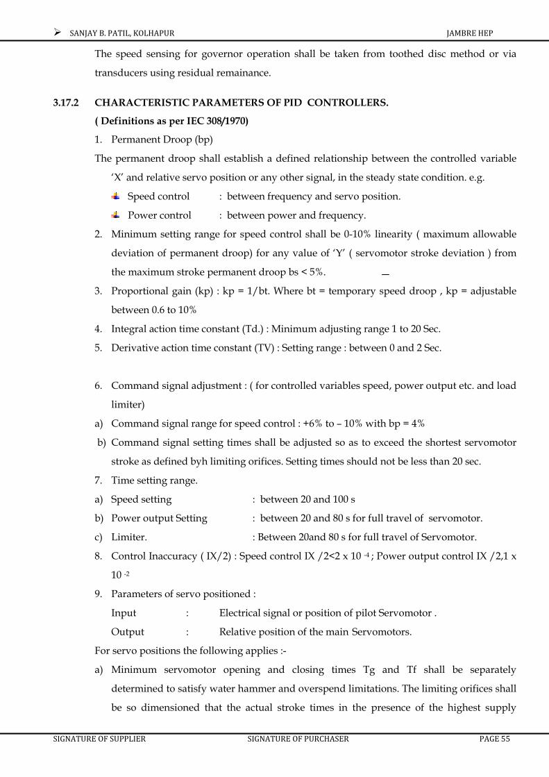
SANJAY B. PATIL, KOLHAPUR JAMBRE HEP
SIGNATURE OF SUPPLIER SIGNATURE OF PURCHASER PAGE 55
The speed sensing for governor operation shall be taken from toothed disc method or via
transducers using residual remainance.
3.17.2 CHARACTERISTIC PARAMETERS OF PID CONTROLLERS.
( Definitions as per IEC 308/1970)
1. Permanent Droop (bp)
The permanent droop shall establish a defined relationship between the controlled variable
‘X’ and relative servo position or any other signal, in the steady state condition. e.g.
Speed control : between frequency and servo position.
Power control : between power and frequency.
2. Minimum setting range for speed control shall be 0-10% linearity ( maximum allowable
deviation of permanent droop) for any value of ‘Y’ ( servomotor stroke deviation ) from
the maximum stroke permanent droop bs < 5%.
3. Proportional gain (kp) : kp = 1/bt. Where bt = temporary speed droop , kp = adjustable
between 0.6 to 10%
4. Integral action time constant (Td.) : Minimum adjusting range 1 to 20 Sec.
5. Derivative action time constant (TV) : Setting range : between 0 and 2 Sec.
6. Command signal adjustment : ( for controlled variables speed, power output etc. and load
limiter)
a) Command signal range for speed control : +6% to – 10% with bp = 4%
b) Command signal setting times shall be adjusted so as to exceed the shortest servomotor
stroke as defined byh limiting orifices. Setting times should not be less than 20 sec.
7. Time setting range.
a) Speed setting : between 20 and 100 s
b) Power output Setting : between 20 and 80 s for full travel of servomotor.
c) Limiter. : Between 20and 80 s for full travel of Servomotor.
8. Control Inaccuracy ( IX/2) : Speed control IX /2<2 x 10 -4 ; Power output control IX /2,1 x
10 -2
9. Parameters of servo positioned :
Input : Electrical signal or position of pilot Servomotor .
Output : Relative position of the main Servomotors.
For servo positions the following applies :-
a) Minimum servomotor opening and closing times Tg and Tf shall be separately
determined to satisfy water hammer and overspend limitations. The limiting orifices shall
be so dimensioned that the actual stroke times in the presence of the highest supply

SANJAY B. PATIL, KOLHAPUR JAMBRE HEP
SIGNATURE OF SUPPLIER SIGNATURE OF PURCHASER PAGE 56
pressure and lowest required regulating capacity is not lower than the allowable stroke
time.
b) Time constant (Ty) of the main servo positioner to be introduced in digital stimulation
system shall lie between 0.1s and 0.25s. Near the zero displacement. Higher values of Ty
shall prevail due to overlap and grooves.
c) Servo positioner inaccuracy in follow up arrangement (ia/2) which has major Influence
on dead band shall be kept small i.e. ,<0.2% for the complete servo positioning system.
d) Control system dead time constant (Tq) shall be less than 0.25s.
e) Dynamic response of servo positioned : Setting of servo positioned shall be so chosen that
the dynamic response of servo positioned corresponding to a damping ratio (D) between
0.8 and 1.1 is achieved.
3.17.3 MANUAL CONTROLS.
Manual control of setting of turbine power directly via the actuators by passing the governor
control loop shall be provided. In that case, the safety of unit shall rest with over sped
protection.
3.17.4 FOLLOW – UP CONTROLS.
To achieve bump – free transition from one operational mode to another following follow-up
controls shall be provided.:
i) The power output governor command signal shall follow the actual power output signal
in the speed control mode.
ii) The speed command signal shall follow the actual frequency – signal in the power output
control mode or during the start up phase ( speed command signal pre- adjustment.)
iii) The manual control set point shall follow the actual actuator position in the various
control modes.
iv) In case of remote control, respective local control shall follow the respective command
signals.
v) It shall be possible to adjust the pre opening of varying heads to minimize start up times.
3.17.5 OPTIMISATION CONTROL :
Special control configuration shall be provided to optimise the system with respect to overall
plant efficiency smooth running or other criteria.
3.17.6 MONITORING, PARALLEL POSITIONING OF AMPLIFIERS.
The deviation of the position of each servomotor from the average of the total shall be
monitored and a warning or shut down shall be initiated when it exceeds the set limit. Also

SANJAY B. PATIL, KOLHAPUR JAMBRE HEP
SIGNATURE OF SUPPLIER SIGNATURE OF PURCHASER PAGE 57
the control deviation of the individual positioning loop shall be monitored. If it does not
return to approximately zero in a given time span a warning or a shutdown shall be initiated.
3.17.7 OPERATIONAL TRANSITIONS :
Following stipulations shall apply :
a) Synchronization Band - ( 0.995 to 1.01) f network.
b) Speed change rate for synchronization : dx /dt = 0.003 per sec.
c) ts/to.8 = no 1.5 to 3.0
Note : ts – Time at which the unit is synchronized.
to.8 – Time at which 80% speed is reached.
d) tE / tM = 2.5 to 4.0
Where tE = Regulating time after which the speed deviation from idling speed remains below
+ 1% t.M= Time after which load rejection takes place.
e) nmin = 0.85 to 0.95 n
nmax = Maximum speed after load rejection (at tM)
nmin = Lower speed after a load rejection.
n = Rated speed.
3.18 HYDRAULIC – MECHANICAL CUBICLE
It shall be consisting of following devices.
1) Electro Hydraulic transducer with hydraulic amplifier “toggle – Baffle’ type.
2) Gate opening limiter.
3) Lever transmission.
4) Feed back shaft.
5) Main slide valve.
6) Contact device of gate limiter.
7) Control mechanism of combinatory cam & limiter as per head.
8) Shaft of limiter.
9) Main feedback gear. .
10) Hydraulic Amplifier with electro magnet.
11) Control and measuring instruments.
12) Double oil filter.
13) Emergency closing solenoid valve.
14) Rotary cam switch bank.
The above units shall housed inside the cubicle mounted on a frame covered with a light
metallic casing. On the face of panel of the cubicle following control and measuring
instruments and indicators shall located which are necessary for the operation of turbine and
governor.

SANJAY B. PATIL, KOLHAPUR JAMBRE HEP
SIGNATURE OF SUPPLIER SIGNATURE OF PURCHASER PAGE 58
1) Electro-Tachometer for measuring speed of turbine.
2) Balance indicator .
3) Gate limiter and gate position indicator .
4) Speed setting indicator.
5) Gate setting indicator.
6) Gate limiter raise/lower hand wheel.
7) Speed change switch.
Inside the mechanical cabinet following shall be located.
1) Oil gauge for indicating the pressure of oil supplied to the hydraulic amplifier.
2) Scale for indicating the head.
3) Gate limiter and gate position indicator shall provided with adequate transmitters to
duplicate indications in the control room.
3.19 OIL PRESSURE UNIT SYSTEM (Common for Turbine, runner blades & MIV)
The oil pressure system shall be amply designed to meet all requirements of governor
(turbine control) system, B.F. Valve. Open-close-open cycle for wicket gates and open- open
cycle for BFV and runner vanes..
i) Purpose
Oil pressure unit system shall be used for operation of the guide vane of turbine, runner
vanes and MIV.
ii) System
a) The pressure oil supply system for each unit shall comprise of 2 sets of pressure oil
pumps directly coupled with the 415 V + 10 % A. C. Motors (1 set for normal operation
and 1 set for stand-by). 1 set of sump tank, 1 set of pressure tank and other accessories.
b) A complete set of compressed air system with one compressor sufficient to develop air
pressure for governing system shall be provided for each governor. One common
compressor shall be supplied as spare.
c) Controls shall also be made from the Unit Control Board in addition to local control.
System shall be suitable for local/ remote and auto control operations.
d) Operation method of the pressure oil pump shall be of the continuous operation type
using unloader valves.
When the normal oil pump stops during operation of turbine or in case of the first stage of oil
pressure drops, stand-by pump shall start automatically.
3.20 OIL SUMP TANK :-
It shall be of electrically welded steel plate having sufficient capacity for two closing &
Opening operations of MIV, Guide vanes and runner blades. The tank shall be totally
enclosed and shall be provided with man hole cover, oil level gauge, level switches for low

SANJAY B. PATIL, KOLHAPUR JAMBRE HEP
SIGNATURE OF SUPPLIER SIGNATURE OF PURCHASER PAGE 59
level alarm return oil strainer, suction and return connection for oil centrifugal equipment, a
filter cum air breather, a thermometer with contact for high oil temperature alarm. The
capacity of oil sump shall be 110% of the oil required for the system comprising Governor,
Guide vanes, servomotor, Pressure accumulator, MIV etc. An on line oil filtration unit shall
be provided for the whole system separately.
3.21 OIL PUMP MOTOR SET
Two triple screw pumps sump tank top mounted vertical type directly coupled to electric
motors of ample capacity to meet all the requirements of governing system shall be provided.
The pumps shall be provided with its own strainer, non-return valve safety valve, idler valve
and discharge isolating valve.
3.22 PRESSURE RECEIVER
It shall be of electrically welded steel plates. It shall have the capacity for closing & opening
operations of MIV, and Guide vanes. The receiver shall be complete with manually operated
air release valve, a fully protected oil level gauge with automatic valves for preventing air oil
loss in case of breakage of the glass. Separate independently changeover contacts to give
alarm for high/low oil level in the receiver shall be provided. A manually operated drain
valve and a pressure gauge shall be provided. The receiver shall have a manhole with door
for maintenance.
Set of pipes and valves for connecting the pressure receiver, pumping set, governor, guide
vane servomotor, MIV shall be supplied.
3.23 OIL LEAKAGE UNIT
The oil leakage unit is intended for the collection of oil leakages from the servomotor. In the
event of maintenance, it shall be used for draining the oil from servomotors, oil pipelines and
guide bearing. The oil shall be periodically pumped from this unit to the sump tank of the oil
pressure system. It shall consists of tank, pump motor set and level relay for controlling the
pump motor operation.
Alternatively Tenderer is free to offer his own design for operating mechanism for runner
vanes, guide vanes and BFV.
3.24 MAIN INLET VALVE
The main inlet valve shall be of conventional disc type butterfly valve of suitable diameter,
tested in works, designed to open under balanced condition and to close against full flow in
emergency. It shall be opened and closed by oil operated servomotor. However, in case of
emergency closing by dead weight shall be possible.

SANJAY B. PATIL, KOLHAPUR JAMBRE HEP
SIGNATURE OF SUPPLIER SIGNATURE OF PURCHASER PAGE 60
MAIN BODY
Main body shall be fabricated from steel plates in halves accurately bored out for the door &
trunnions and complete with gun- metal bushes bearings and cup seals for the trunnions and
stainless steel sealing ring for the main seal.
DOOR
Door shall be cast steel / fabricated steel with trunnion. The trunnion shall be lined with
stainless steel plates where they pass through.
SEALING DEVICE
Consisting of adequately reinforced rubber sealing ring fixed by rustless screw and sealing
against stainless steel ring in the main body.
DISMANTLING JOINT WITH DOWNSTREAM PIPE
It shall be of steel, of the telescopic type, situated on the down stream of valve. This would
facilitate dismantling of the valve during maintenance. The dismantling joint shall be suitably
designed either to transmit the hydraulic thrust in the penstock to down stream of valve or
may act as a dismantling cam expansion joint depending upon whether the thrust is required
to be transmitted down stream of valve or sustained on the upstream by some means.
LEVER
It shall be of cast / fabricated steel keyed to the trunnion and with gunmetal bush for the
servomotor connecting rod.
SERVOMOTOR
Servomotor shall be comprising of fabricated steel cylinder with covers, cast steel pistons,
stainless steel piston rod and complete with sealing gland, pipe connection, timing
diaphragms etc.
BYE-PASS VALVE AND PIPING
It shall comprise of hand operated sluice / wedge gate valve, bye pass valve, bye pass pipe
etc. The sluice/ wedge gate valve shall be provided on upstream of the bye pass valve as a
guard valve. The bye pass valve shall be oil operated or electrical actuator operated with limit
switches etc. for balancing pressure across the main inlet valve. The bye pass piping of
suitable length joining upstream to down stream of valve with necessary flanges, fasteners
and packing shall be provided. Stand by manual valve, operated manually shall also be
provided.
SANJAY B. PATIL, KOLHAPUR JAMBRE HEP
SIGNATURE OF SUPPLIER SIGNATURE OF PURCHASER PAGE 61
AIR VALVES
It shall be automatic operating type of valve to supply or release the air during draining off
and filling the spiral casing. It shall be mounted on down stream of valve.
UPSTREAM PIPE
It shall be of electrically welded mild steel with a flange for connecting to the B. F. V. on
upstream side and other side shall be prepared for welding to the penstock.
SET OF SUNDRY MATERIAL
These shall be consisting of sundry items such as foundation bolts, sole plates, lifting
brackets, jointing material etc.
3.25 DEWATERING AND DRAINAGE SYSTEM:
DEWATERING SYSTEM
One turbine dewatering system shall be provided for dewatering all the hydraulic Portion i.
e. from penstock gate to draft tube gate. The individual draft tube shall be connected to the
watering sump through pipe and isolating valve / from where water shall be pumped out
through common discharge header into tailrace. Two pump motor sets (Submersible type) of
adequate capacity shall be provided for dewatering all the hydraulic paths. The pump motor
shall be suitable for operation on 415 V +10%, volt, 3 phase, 50 Hz. Level electrode shall be
provided to start / stop the pumps automatically & to give alarm if water level rise beyond
pre set limit in sump The dewatering system shall be suitably designed & shall be complete
with adequate of isolating valve, non-return valve, pressure gauge, piping, fitting, support
etc. Motor starters, protective devices, indicating lamps etc shall be mounted on local control
panel.
DRAINAGE SYSTEM
Two drainage pumps ( one working & one standby ) of adequate capacity to remove
normal seepage & drainage water along with necessary piping, valves & fittings shall be
provided. The motors shall be of ample rating suitable for continuous duty and mounted at
the pit. The automatic control of the pump units shall be arranged through float switches to
start the pumps automatically when the water level in pit rises up to the pre-determined
level. The pump motors shall be suitable for operation on 415 + 10% volt, 3 phase, 50 Hz. The
arrangement of drainage & dewatering system shall be proposed by the Contractor.
3.26 COOLING WATER SYSTEM
The cooling water for generator & turbine bearing coolers shall be taken from upstream of
main inlet valve from penstock. The system consists of suitable size/ capacity of isolating
valves, duplex strainer, booster pump motor set, piping, fitting, supports, flow meters. The

SANJAY B. PATIL, KOLHAPUR JAMBRE HEP
SIGNATURE OF SUPPLIER SIGNATURE OF PURCHASER PAGE 62
duplex strainer shall be manually operated type fitted with pressure switch to give alarm in
case the pressure difference across it exceeds a preset value. Pressure gauges shall also be
provided to indicate the water pressure at its inlet & outlet.
Booster pump motor set, one number, is required to increases the pressure of water to desired
value for each turbine and generator. The motor shall be complete with starter, protective
device, indicating lamps, etc. One number motorized isolating valve shall be provided on
each suction line near generator barrel for automatic starting / stopping of cooling water.
The cooling water exhaust shall be discharged into the tailrace above high flood level.
3.27 CENTRALISED GREASE LUBRICATION SYSTEM
The centralized grease lubrication system shall be of adequate capacity to pressure the
turbine lubricating system periodically by timer as per requirement. The equipment
comprises of electric motor drivers grease starter, grease reservoir, pressure regulator, set of
solenoid valves ,grease dossers and piping etc One hand operated pump shall be supplied for
filling grease reservoir.
3.28 COMPRESSED AIR SYSTEM
One set of H.P. compressed air system shall be provided for complete power house for
intermittent supply of air to cater the needs of governor oil pressure for governing of turbine
& generator brakes comprises of the following .
a) Two Nos. of A.C. driven motor air cooled air compressors one acting as main and other
as a standby and each of adequate capacity to cater the above needs for complete power
house. The standby compressor shall start automatically on failure of the main
compressor.
The compressor motor shall be rated for 415 volt + 10%, 3 phase, 50 Hz and provided with
suitable starter, protective devices etc, on local motor control panel.
b) The air from individual compressor shall be passed through common air cooled after
cooler and accumulated in common H.P. air receiver fitted with pressure gauge, safety
valve & manual drain trap. For automatic starting/stopping of motor and very low air
pressure alarm, pressure switches shall be provided.
c) Piping, fitting, pipe supports, adequate numbers of isolating valve, non-return etc. shall
be provided.
OIL
The contractor shall supply all the oil required for the first filling Governor oil system and the
lubrication system of turbine. Sufficient quantities of grease and other lubricants required for
the first filling of the lubricating systems shall also be supplied by the contractor. The oil used
for the governor & oil pressure system shall be identical with that used for the lubrications of

SANJAY B. PATIL, KOLHAPUR JAMBRE HEP
SIGNATURE OF SUPPLIER SIGNATURE OF PURCHASER PAGE 63
the turbine guide bearing and also shall be identical with the oil used for the lubrication of
generator thrust & guide bearings. The contractor shall give his recommendation regarding
the type of oil.
3.29 SPECIAL TOOLS, SLINGS, CONSUMABLES
All special tools, slings, lifting devices, jacks, turn buckles, foundation plates / bolts etc.
required for erection of the equipments shall be listed & supplied. Welding electrodes as
required for site welding and paint for finishing coat shall be supplied by the supplier.
3.30 SPARES
The spare parts for the turbine and associated equipments considered necessary for five years
of operation of the generating unit shall be supplied by the supplier along with the first
turbine.
3.31 GENERATOR COOLING SYSTEM, BRAKES & PAINTING, CORROSION
PROTECTION AND COATING
3.31.1 COOLING SYSTEM
The generator shall be naturally air cooled. Fans shall be designed to give a smooth and quiet
flow of air in the stator and rotor. Bid shall indicate the various design features to control
temperature rise in the stator including the end windings, rotor, shaft and exciter.
3.31.2 BRAKES
Generator shall be provided with Hydraulic brakes which will operate automatically. The
generator brake system shall consist of suitable number of brake shoes. It is the responsibility
of the generator manufacturer to ascertain the type of system being proposed by the turbine
manufacturer. The brakes shall be capable to be applied at not more than 20% of maximum
speed. It shall be possible with the braking equipment to retard the unit, to standstill within
2 minutes from time when brake impulse is transmitted.
3.31.3 PAINTING, CORROSION PROTECTION AND COATING
For all structural steel and cast iron parts the following applies:
Surface Preparation: On all cast iron and structural steel parts the rust must be
removed by mechanical means (sandblasting) to obtain a bare surface according to
International Standard.
Prime Coat for all areas: 2 layers with "Friazinc R", dry thickness of each layer 40
microns.
Type A : Areas in contact with oil (if required): All those areas will receive three coats
with oil resistant paint, for example Keratol, which must be applied as finishing coat.

SANJAY B. PATIL, KOLHAPUR JAMBRE HEP
SIGNATURE OF SUPPLIER SIGNATURE OF PURCHASER PAGE 64
Type B : Areas in contact with air: All those areas still accessible after assembling on
site, receive two prime coats with different colors. The prime coat consists of a
preliminary final coat in blue for the generator casing and red for all the moveable
parts. The applicable RAL colours will be provided after placing of contract.
Areas in contact with concrete: Cast-in items do not receive any coating, but must be
free of rust and spunk.
Cast-in items exposed to air and water must be provided with a prime coat to a depth
of approximately 150 mm into the concrete.
Oil carrying pipelines (if required): They must be dismantled after assembling on site,
pickled in acid solution neutralized and oiled. Pipe prefabricated and pickled in the
factory then shipped to site with all holes and access points sealed, do not have to be
treated again at site but should be flushed out as part of the assembly procedures
All bare surfaces, which are not in contact with oil, shall be provided with a protection coat
(removable with water) after manufacturing. Parts located in inaccessible areas, which must
not be dismantled after workshop assembling must be protected as follows: -
The electrical equipment such as electric motors, limit switches, control panels etc. must
receive corrosion protection according to specifications for the worst atmosphere. The colour
coding will be determined by the Purchaser.
Any coated surface damaged after or during assembling must be reinstated. Internal and
external surfaces of the casing and all metal parts shall be painted with epoxy paint that will
resist corrosion due to ambient conditions. The color of external paint will be confirmed
during detailed design and must be of non-hazardous and non- toxic nature.
3.32 CONSTRUCTION
GENERATOR
Horizontal shaft synchronous alternator of capacity 2310 KVA at 0.866 p.f. 3.3 KV, 50Hz,
three phase suitable for coupling to above mentioned turbine with brushless excitation
system with Automatic voltage regulator etc. complete, with Generator auxiliaries
comprising S.S.G. unit, H.S. Lubrication system, brake/ jack system, Fly Wheel stator
encloser, railing & coverings, coolers, heaters, cables etc. complete.
3.32.1 STATOR
The stator frame shall be of fabricated steel construction. The frame shall be designed to
withstand bending stresses and deflections due to its self weight and weight of the complete
core to be supported by it. The stator core shall be built up of segmental punching of low
loss, non-oriented steel sheets and end plates. Each punching shall be carefully de-burred

SANJAY B. PATIL, KOLHAPUR JAMBRE HEP
SIGNATURE OF SUPPLIER SIGNATURE OF PURCHASER PAGE 65
and insulated on both sides with high quality varnish to reduce losses in the core. In addition
to above, stator frame shall withstand the stresses from other operating conditions stated in
this subsection.
The stator winding shall be of copper (99% purity) which can be of multi-turn or single turn
type and shall be insulated with Class F insulation and shall be so designed to suppress
harmonics to achieve a full sine wave. The stator winding shall be star connected with both
ends of conductors of each phase brought out of the stator. The outlets shall be enclosed and
the outlet box shall be adequate for connection of specified power cable.
For each generator, for stator winding (located between top and bottom coil sides)
symmetrically located embedded resistance temperature detectors shall be provided. The
connections on the resistor elements shall be well insulated and extended to a connection box
on the outside of stator frame.
3.32.2 ROTOR
The design and construction of salient pole rotor shall be in accordance with the best modern
practice. The factor of safety at maximum runaway speed based on yield point stress of
material shall be not less than 1.5.
The rotor bars shall be short-circuited with end rings by an appropriate method like
induction brazing method. The copper end rings of the rotor shall be well supported by steel
retaining rings to make the rotor sturdy to withstand runaway speeds and other operating
conditions specified under this specification. Field winding shall consist of fabricated field
coils or any other type with adequate provision for cooling purpose. The field poles shall be
provided with adequate damper windings to ensure stability under fault conditions and to
meet I22t value of 20.
3.32.3 TERMINAL BOX
The terminal box shall be located on either side of the generator-one for phase connection and
other for neutral connection. A separate terminal box for RTD’s and space heater terminals
shall be provided. The terminal box shall be suitable for taking 6.6 kV cable of adequate size
and specification.
3.32.4 PHASE MARKING
Appropriate phase marking as per IS: 325 shall be provided inside the terminal box. The
markings shall be indelible.
3.32.5 SHAFT AND COUPLING
The generator shaft shall be made of the best quality carbon steel forging properly heat-
treated. The shaft shall be of adequate size to operate at all speeds including maximum
runaway speed and shall be able to withstand short circuit stresses without any vibrations or
SANJAY B. PATIL, KOLHAPUR JAMBRE HEP
SIGNATURE OF SUPPLIER SIGNATURE OF PURCHASER PAGE 66
distortion. The generator shaft shall be accurately machined all over and polished where it
passes through the bearings and accessible points for alignment checks. Generator shaft shall
have suitable provision for coupling to turbine.
The main shaft shall have an integrally forged flange for connection to turbine shaft flange.
All coupling dimensions shall be agreed upon by the turbine and generator manufacturer and
shall essentially conform to IEEE 810 “IEEE standard for hydraulic turbine and generator
integrally forged shaft coupling and shaft run out tolerances” or an equivalent approved
standard.
The generator manufacturer shall be responsible for the alignment and balancing of the rotor
with the turbine shaft and runner after installation in accordance with the stipulations laid
down in NEMA publication LG3 latest edition.
3.32.6 BEARINGS
The generator bearings shall be preferably anti friction ball / roller bearings oil or grease
lubricated. In case pedestal type bearing are supplied these shall be pad type or sleeve type
with Babbitt metal lined with oil lubrication. These bearings shall be guaranteed for
minimum continuous working for 150,000 (one lakh fifty thousand) hours and shall be of
proven design and performance and shall require minimum maintenance. The detailed
drawings and dimensions shall be supplied by the bidder with the offer.
Bearings shall be adequately insulated to prevent any harmful circulating currents. The Drive
End bearing shall be of thrust cum journal bearing and Non Drive End bearing shall be
journal bearing. The thrust bearings shall be suitable to take axial thrusts in both the
directions. The bearings shall be designed to withstand operation of runaway speed for 15
minutes. Thermometers, grease-lubricating points, speed relays etc. as required shall be
provided.
Each of the bearings shall be provided with dial type thermometer and also provided with
two sets of contacts for annunciation and trip of the machine. The bearings may also be
provided with resistance elements. Wires shall be run from thermometer and resistor
element to the instruments and the junction box mounted on the outside of the stator frame.
3.32.7 FLYWHEEL (IF REQUIRED)
A separate flywheel of ample dimensions shall be supplied in case the required moment of
inertia for limiting the speed rise/runaway speed is not available from the generator rotor
exciter, etc. The flywheel shall be coupled to the generator directly and to the turbine (if
required)
3.32.8 VIBRATION

SANJAY B. PATIL, KOLHAPUR JAMBRE HEP
SIGNATURE OF SUPPLIER SIGNATURE OF PURCHASER PAGE 67
All rotating parts shall be designed to operate without undue vibration. The vibration level
of the machines shall be within the limits specified in IS 4729. The maximum vibration level
shall be 150 microns (peak-peak value). The balancing shall be done to a maximum extent at
the plant and shall be repeated for the entire unit before COD.
3.32.9 OIL & GREASE
The bidder shall indicate the lubrication requirement and give his recommendations with
detailed specifications regarding type of grease to be used and frequency of refilling required
for lubrication of generator bearings. The oil, if used for generator bearing lubrication shall
be, as far as possible, identical with that used for the turbine pressure oil system. The first
filling of oil with 10% extra quantity shall be supplied along with the generator.
3.33 SPEED RELAY, TOOTHED WHEEL & MECHANICAL OVERSPEED
A toothed wheel arrangement is to be mounted on the shaft of the generator and a photo
interceptive pick up has to be mounted on a bracket and connected to speed relay mounted
on turbine control panel through a special screened cable. Further, a mechanical over-speed
device shall also be provided to stop the unit during over-speed and this should directly act
on the oil pressure system to stop the machine.
3.34 EXCITATION SYSTEM
The excitation system shall be of Brushless type with digital automatic voltage regulator
(AVR) to maintain the output terminal voltage constant and reactive power within the
regulation limits. The excitation system offered shall be capable of joint control. The AVR
shall continuously sense the generator output terminal voltage and provide excitation voltage
to the field of the generator to limit the regulation within ± 1% over the entire range from no
load to full load.
It shall include excitation transformer connected directly to generator terminal (dry type),
thyristor cubicle, field breaker cubicle, flexible copper connections between field breaker and
slip rings etc. Inter connections between thyristor and field cubicles shall be in supplier scope.
The excitation system shall have redundancy facility.
The bid shall contain complete technical details of the equipment being offered for optimum
operation.
3.35 NEUTRAL GROUNDING SYSTEM (NGS)
All three phases from Generator terminal will be brought to Neutral Grounding Cubicle.
These three phases will be shorted in NG cubicle. Current transformers will be mounted on
neutral side before shorting of three phases. The neutral point of the star connected stator of
each generator shall be grounded through 3.3 KV/110 V/√3 single phase, dry type
distribution transformer with loading resistor of adequate rating connected across the

SANJAY B. PATIL, KOLHAPUR JAMBRE HEP
SIGNATURE OF SUPPLIER SIGNATURE OF PURCHASER PAGE 68
secondary winding. Suitable terminal arrangement with neutral isolating switch shall be
provided. The isolating switch shall be of manually operated type. The Generator terminal
CTs shall be mounted in this cubicle. All the above neutral grounding equipment will be
housed in a drip proof enclosure. The rating of the grounding transformer, secondary resistor
and isolating switch shall be indicated in the tender. Calculations for working out the ratings
shall be submitted by the successful bidder to the purchaser/consultant for their approval.
The following design parameter shall be considered
The transformer shall be of cast resin type
The insulation level shall be adequate for rated system voltage.
95% of stator winding are to be protected.
The load resistor shall be selected such that the total losses of the resistor are equivalent to
the generator/transformer capacitive reactive losses when phase/neutral voltage is
applied to the primary side of the transformer.
All the generator neutral earthing equipment including CT’s as shown in the Single Line
Diagram shall be installed in the sheet steel cubicle. The technical data of the equipment
such as ratio/accuracy/burden/knee voltage point shall be co-ordinated with the
protection and metering system.
The equipment shall be housed in a floor mounted cubicle, suitably compartmentalized with
steel frame and bolted panels. The cubicle is arranged and built to provide adequate natural
ventilation of the equipment. The cubicles shall be complete with base mounting
arrangement. The internal illumination for cubicles shall be provided with guarded lamps
with on/off switch. Copper conductors of appropriate size shall be used for connections in
the cubicles. The cubicle shall be drip proof. The three phase compartment shall be at the top
and shall be separated from the neutral grounding transformer and resistor.
3.35.1 3.3 kV CURRENT TRANSFORMER
The current transformers will be epoxy cast, dry type units conforming to IS: 2705. The
current transformers shall be designed to withstand the thermal and magnetic stresses from
the maximum short circuit current. The accuracy class shall be 1 for metering and Class 5 P 20
or Class PS (as applicable) for protection. The CT locations, rating, accuracy class shall be
suitable for adequate metering and protection.

SANJAY B. PATIL, KOLHAPUR JAMBRE HEP
SIGNATURE OF SUPPLIER SIGNATURE OF PURCHASER PAGE 69
CT- A
Core
No.
Transformation
Ratio/ Utilization
Acc.
Class/Burden
Knee Point
Voltage
(Volt)
Secondary
Resistance
(Ohm)
Magnetizing
Current @
Vk/2 (mA)
Core-I 600/1A, Gen. protection
5P 20/50VA NA NA NA
Core-II 600/1A, Metering CL 1/50VA NA NA NA
Core-III 600/1A,/Spare PS/NA >=300 <= 1.5 <=15
Core-600/1A, Gen. Diff. Protection
PS/NA >=300 <= 1.5 <=15
3.36 LAVT CUBICLE
One no LAVT panel for each generator shall be provided. The cubicles shall be of sheet steel,
suitably, compartmentalized with doors and shall be furnished complete with base mounting
arrangement, foundation bolts, etc. The internal illumination for cubicles shall be provided
with guarded lamps with on/off switch. Aluminum conductors of appropriate size shall be
used for bus bars and connections in the cubicles. The bus bar and main & connecting
conductors shall be suitably insulated to make them compatible with generator temperature
rise and insulation. The support insulators for the bus connection shall be provided as
necessary. GI earth bus of adequate cross-section will be provided in the cubicle. The cubicles
shall have rigid frames of rolled steel sections supported on a steel channel base. Welded
parts shall be carefully cleaned and phosphated after assembly. Panels shall be removable
single piece steel plates, with a minimum thickness of 11 gauge, bolted to the frame. No part
shall be subject to excessive heat rise and natural ventilation shall be supplied. Doors shall be
equipped with key operated locks. Clearances between live items and the mass shall provide
adequate insulation. Suitable tapping connection shall be provided for metering & protection
PT and AVR power & sensing PTs. Current transformers shall also be accommodated in
LAVT. The cables from stator shall be terminated in LAVT. Also, cables shall be emanating
from LAVT to the LV side of transformer.
3.36.1 POTENTIAL TRANSFORMERS
The potential transformers will be single phase, epoxy, cast, dry type 6.6/1.732kV/110 V
Twin core, 100 VA units. Potential Transformer will be protected on primary and secondary
side by current limiting fuses. The PT shall conform to IS: 3156 and shall have parameters as
indicated in legends sheet. One core suitable for protection and the other one for metering.

SANJAY B. PATIL, KOLHAPUR JAMBRE HEP
SIGNATURE OF SUPPLIER SIGNATURE OF PURCHASER PAGE 70
3.36.2 LIGHTNING ARRESTORS
The lightning arrestors shall be heavy duty, indoor station class and non-linear resistor
gapless types suitable for repeated operation to limit voltage surges on alternating current
power circuits and to interrupt power follow current. The arrestors shall conform to IS: 3070
(latest edition) part- I. The nominal discharge current of lightning arrestor shall not be less
than 30 KA.
3.36.3 SURGE CAPACITORS
The surge capacitors shall conform to the latest edition of IS: 2834 and shall be rated 0.25
Micro Farad. The capacitors shall be connected in parallel with lightning arrestors and shall
be provided with a built in discharge resistor. The capacitor shall be suitable for indoor
mounting.
3.36.4 CURRENT TRANSFORMER
The current transformers will be epoxy cast, dry type units conforming to IS: 2705. The
current transformers shall be designed to withstand the thermal and magnetic stresses from
the maximum short circuit current. The accuracy class shall be 1 for metering and Class 5 P 20
or Class PS (as applicable) for protection. The CT locations, rating, accuracy class shall be
suitable for adequate metering and protection. C.Ts will be used for neutral circuit.
CT- B
CoreNo.
Transformation
Ration/
Utilization
Acc.
Class/Burden
Knee Point
Voltage
(Volt)
Secondary
Resistance
(Ohm)
Magnetizing
Current @
Vk/2 (mA)
Core-I 600/1A,AVR 1/50VA NA NA NA
Core-II 600/1A, Bus-Bar
Protection PS/NA >= 300V <= 1.5 <= 15
Core-III
600/1A,
Generator Diff.
Protection
PS/NA >= 300V <= 1.5 <= 15
Core-IV Spare PS >= 300V <= 1.5 <= 15
3.37 SPARES
Spare parts of the generators considered for five (5) years of trouble free operation of the
units shall be supplied as per Schedule 1 of Schedule of Requirement Section-V.
3.38 TESTS
Each generator shall be tested in assembled condition as detailed below.

SANJAY B. PATIL, KOLHAPUR JAMBRE HEP
SIGNATURE OF SUPPLIER SIGNATURE OF PURCHASER PAGE 71
3.38.1 TESTS AT SUPPLIER'S WORKS (SHOP TESTS)
The generator shall be completely assembled at manufacturer's works and following type
tests as per IS: 4722- 1992 standards or equivalent International Standards are to be carried
out on first generator only. Test shall be carried out in presence of Purchaser/Consultant.
Measurement of winding Resistance.
Insulation resistance test (before and after the HV test)
High Voltage Test
Determination of generator characteristics
Measurement of open-circuit Characteristic.
Measurement of short-circuit Characteristic.
Temperature rise test by indirect method.
Measurement of shaft Voltage.
Dielectric strength test
Moment of inertia test
Occasional Excess Current Test; 150% of rated current at short circuit condition for 15 sec.
Phase Sequence Test.
Measurement of voltage waveform distortion factor at no-load.
Over speed test shall be done on 120% of rated speed for 2 min.
Efficiency test by summation of loss method
Line charging capacity
Temperature rise test
Type test on panels for IP: 55 protection as per IS:13947. After this test, insulation
resistance (2.5kVrms for 1 min) and functional test on control devices shall be conducted.
Additional tests as recommended by manufacturer, as mutually agreed between
Purchaser and supplier
3.38.2 ACCEPTANCE TESTS
Following acceptance tests shall be carried out on two generators in assembled condition after
shop tests:
Measurement of winding Resistance.
Insulation resistance test.
High Voltage Test
Measurement of open-circuit Characteristic.
Measurement of short-circuit Characteristic.
Measurement of shaft Voltage.
Dielectric strength test
Moment of Inertia test

SANJAY B. PATIL, KOLHAPUR JAMBRE HEP
SIGNATURE OF SUPPLIER SIGNATURE OF PURCHASER PAGE 72
Phase Sequence Test.
Additional tests as recommended by manufacturer, or as mutually agreed between
Purchaser/Consultant and Supplier
3.38.3 SITE TESTS
Prior to acceptance of the equipment, the supplier shall carry out a series of tests as detailed
below. The contractor shall provide duly calibrated test instruments and equipment including
any special test equipment that may be needed. The tests shall be conducted on each
generator as per IS, IEC or equivalent standards.
Mechanical run
Run away speed test
Measurement of winding insulation resistance (before and after HV tests )
High Voltage dielectric test
Measurement of shaft voltage
Phase sequence tests
Braking test for verifying braking time.
OCC/SCC tests
Measurement of winding resistance
Measurement of vibration & noise level
Synchronizing Test
Excitation system response test / check
Field acceptance and Efficiency test by summation of losses method or any equivalent as
per IEC(to be conducted on only one unit).
Load acceptance and rejection tests at selected load from "no load" to "full load".
Vibration measurement
Wave form analysis
Tests on excitation equipment
Operational tests on all generator auxiliary including calibration of related electrical
indicating , control and metering instruments.
Check for correctness of electrical wiring
Any additional tests as mutually agreed such as measurement of slip / power factor etc.
3.38.4 OUTPUT TESTS
Load test shall be carried out at site for seventy two hours to show rated output on each
generator before releasing for commercial operation.

SANJAY B. PATIL, KOLHAPUR JAMBRE HEP
SIGNATURE OF SUPPLIER SIGNATURE OF PURCHASER PAGE 73
3.39 TESTING EQUIPMENT
All testing equipment including HV test kit and vibration measurement equipment required
for testing of the generator at site shall be provided by the Supplier free of charge and taken
back after testing is completed.
The torque for onsite test must be measured as well. In the event repeated testing becomes
necessary, the entire expenditure on such repeat tests shall be borne by the Supplier.
3.40 CHARACTERISTIC CURVES
The generator characteristic values for determination of performance shall be arrived either
through circle diagram method or equivalent circuit method after conducting all required
tests on the generator even though they have not been specifically mentioned above.
After testing the machine, the equivalent circuit of the generator, phase diagram and the
performance characteristics like load versus efficiency; load versus power factor or load
versus magnetizing kVAR, kVA and kW output and load current shall be determined and
furnished to Purchaser/Consultant by the Supplier.
Tests on other equipment like auxiliaries, CTs, PTs, LAs shall comply with the routine tests
etc. as per relevant standards.
3.41 INDICATING INSTRUMENTS, CONTROLS AND SAFETY DEVICES
A list of indicating instruments, controls and safety devices are indicated in Schedule-l
enclosed with these specifications. The bidder shall also include those instruments, controls
and safety devices necessary for safe and efficient operation of unit even though not
specifically mentioned in the Schedule.
3.42 ERECTION, TESTING AND COMMISSIONING
The Supplier shall depute his experts to carryout erection, testing and commissioning of
generators and other associated and auxiliary equipment connected with the powerhouse
and duly hand over the same to the satisfaction of the Purchaser. This work shall be included
in the scope of contract and nothing extra shall be paid on this account. The Supplier shall
train the staff of the Purchaser on the job and instruct them during maintenance.
This covers AC generator complete with static excitation system, Automatic voltage
regulating equipment, neutral grounding and generator terminal equipments, including CTs,
PTs, surge protection equipment etc. and auxiliaries such as generator fire fighting system
equipments, lubrication system, oil, water and air piping with valves and fittings,
instrumentation controls and safety devices (as required), spares for 5 years operation of the
plant, special tools and testing devices. The scope of supply shall include all parts,
accessories, spares etc. which are essential for construction, operation and maintenance of the
complete generator even though these are not individually or specifically stated or

SANJAY B. PATIL, KOLHAPUR JAMBRE HEP
SIGNATURE OF SUPPLIER SIGNATURE OF PURCHASER PAGE 74
enumerated. Corresponding components of the generator and associated equipments and
the spares shall be of the same material, dimensions and finish and shall be interchangeable.
The position of electrical control shall be such that it is easy for operator handling the
equipments.
The generator manufacturer shall co-ordinate with the turbine supplier so that the turbine to
be coupled to the generator is matched in respect of speed , runaway speed, moment of
inertia, overload capacities, coupling and other relevant requirements.
THE RATING AND OTHER DETAILS OF THE GENERATOR ARE GIVEN BELOW:-
1) Rated continuous output - 2.0 MW + 10% continuous over load
2) Power factor - 0.866 under excited(lag)
3) Frequency - 50 Hz+3%, & -5%.
4) No. of phases - 3, neutral brought out.
5) Rated terminal voltage between phase - 3.3KV
6) Range of voltage variation between phase for rated - ± 10% output.
7) Range of frequency variation - + 3% & -5%.
8) Direction of rotation - Clockwise as seen from generator front side i.e.opp.to runner.
9) Short circuit ratio - Not less than 0.8.
10) Inertia constant - Not less than 1.0.
11) Stator winding connection - Star connection.
12) Speed - to be decided by the manufacturer
The generator will be coupled to the turbine. Generator shall be star connected and the main
and neutral leads shall be brought out of the stator frame for insertion of current transformers
for protection, metering and surge protection apparatus etc.
3.43 TYPE AND RATING
The generators shall be synchronous, & of the horizontal shaft water wheel driven alternating
current type. Generator neutral shall be grounded and the generator shall be designed to
safety withstand any mechanical/magnetic stresses resulting from either a three phase or a
single- phase short circuit fault.
The machine shall be designed to ensure continuous operation at 110% of rated output
without exceeding the max. temp. rise of stator & rotor coils specified in the specification.
The generator shall comply in all respect with the requirement of the latest issue of Indian
Standard IS : 4722 except where specified otherwise.
3.44 SPEED RISE AND RUNAWAY SPEED
The moment of inertia of the generator together with the moment of inertia of the turbine
shall be such that the maximum momentary speed rise shall not exceed 50% of the rated

SANJAY B. PATIL, KOLHAPUR JAMBRE HEP
SIGNATURE OF SUPPLIER SIGNATURE OF PURCHASER PAGE 75
speed. The generator manufacture shall co-ordinate with the turbine manufacturer to limit
the speed rise to this value.
The generator shall be designed and constructed so as to be capable of running for a period of
15 minutes at the maximum runaway speed. The runway speed test shall be considered
successful if, after undergoing the test, no injury is apparent. The runaway speed test may be
carried out at site for which suitable foundation based on the loading data to be given by the
Contractor.
3.45 INSULATION AND TEMPERATURE RISE
Insulation shall be provided as follows :
i) Stator Winding Material corresponding to Class –F
ii) Rotor winding Material Corresponding to Class – F
The output of generator should be 2310 KVA at 0.866 (lagging) p.f. with temperature rise of
the winding limited to class “B” insulation corresponding to ambient temperature of 450 C
but the actual insulation of winding should be confirming to Class-F.
3.46 TEMPERATURE RISE
The generator shall be capable of delivering its rated output continuously at any voltage
within the specified voltage limits, and frequency, within the temperature rise of any
part of the generator exceeding the values given in Indian Standard No. 4722 - 1968
(and / or latest amendment thereof) for Class “F" type insulation except where the
permissible temperature rise is otherwise modified in this section of the specification.
The temperature of the armature and field windings will be determined by resistance
method. This test shall be carried out at shop.
The generator shall be capable of operating continuously at the rated output of 2310 KVA
with 0.866 power factor under excited (lagging) in Zone-A, without exceeding the
temperature beyond 1200C corresponding to ambient temp. of 450C i.e. with in the operating
temperature limit for Class-B insulation. The generator should also be capable of operating
continuously in Zone-B as per IEC – 341 for worse combinations of terminal voltage and
frequency.
3.47 GENERATOR NEUTRAL EARTHING :
The neutral point of the generator shall be earthed independently through primary to single
phase transformer of suitable value and rating. A resistance of suitable value shall connected
across secondary. The ohmic value & kilowatt rating of the resistor and the KVA capacity &
voltage ratio of Neutral grounding transformer shall be such that the transient over voltage
on the stator winding during phase to ground fault on the generator shall be reduced to the
minimum value possible and any phenomenon such as Ferro-resonance is also avoided. The

SANJAY B. PATIL, KOLHAPUR JAMBRE HEP
SIGNATURE OF SUPPLIER SIGNATURE OF PURCHASER PAGE 76
ohmic value of the resistor shall preferably be such as to limit the fault current to a value
approximately equal to capacitive current to a ground during a single phase to ground fault
on the generator so as to minimize the transient over voltage on the stator windings. Suitable
arrangements for connection between stator neutral terminal & N.G. transformer is to be
provided by Contractor.
3.48 AUTOMATIC VOLTAGE REGFULATOR
1) Voltage regulator shall be AVR type. It shall be liberally designed so as to be as reliable
as possible and shall incorporate sufficient redundancy so that failure of any control
equipment will not cause mal operation of the system.
2) The voltage regulator should periodically reference values. Calculations should be
repeated at every short time intervals where by an apparently continues regulator output
characteristics is produced.
3) Calculations to be carried out in binary system. The analog measured values of generator
voltage and current as well as field current must be transformed in an analog/Digital
converter into binary signals. Form the calculated control signals; pulses should be
generated for firing the thyristor.
4) Various control functions like voltage regulation, limitations of field current, rotor stator
current slip stabilizing etc. shall be stored s programs to be executed in a cyclic pre-
programmed manner.
5) Control to maximum converter voltage shall be achieved in less than 10 milliseconds thus
ensuring fast reaction to network disturbances.
6) Internal conditions monitoring of devices with light emitting diode (LED) indication be
provided which means short failure detection times
7) Set values shall be digital, absolutely reproducible and not vulnerable to changes
ensuring long term stability.
8) Number of different units shall be small so that spare parts stock could be kept to a
minimum.
9) Low sensitivity to external electro-magnetic influences shall be ensured which means
high noise immunity.
10) Electrical control points shall be bare minimum to reduce potential trouble sources.
11) Comprehensive measuring and setting shall be possible which should enable direct
setting of characteristics values without the necessity of calibration instruments.
12) The l voltage Regulator shall perform following functions.
Regulation of generator voltage.
Limitation of field current.
Limitation of rotor angle.

SANJAY B. PATIL, KOLHAPUR JAMBRE HEP
SIGNATURE OF SUPPLIER SIGNATURE OF PURCHASER PAGE 77
Limitation of stator current.
Stabilization of power pulsations.
Stabilization of power pulsations.
Power factor control.
13) A local control, input and display unit shall be provided for communications with the
processing unit during operation. It should be possible, from this control unit, to call up
the stored parameters, measured values etc. and to change control parameters such as
limit values or characteristics values of the control alogorithms.
14) It should be exceptionally reliable with no changes in operating performances. If failure
should occur it should announce itself so that it can be removed fast.
15) Cross current compensated should be provided to prevent reactive current flow from one
unit to the other.
16) Active power restriction shall form a part to ensure prevention of stator core local
overheat, field and stator windings over heating
17) Frequency drop compensation shall be provided to ensure over excitation compensation
of transformer in the event of low frequency.
18) Automatic reactive power compensation or power factor regulation should be provided.
The power factor regulating range shall be manually adjustable from lagging power
factor 90% to leading power factor 90% at rated output and rated voltage.
19) Current regulating equipment :
The current regulating equipment shall be provided in order to approach the operating
power factors to unity when the generator current exceeds 105% of the rated current due
to a voltage drop during generating operation.
20) In case the load is rejected due to any external fault during generating operations at the
rated output, rated voltage and rated power factor, the voltage rise of the generator shall
be less than 20% with speed regulation of 35% without opening the field circuit breaker.
21) Emergency demagnetizing device.
Emergency demagnetizing device shall be provided so as to perform quick
demagnetization of generator in the event of electrical internal fault of the generator.
22) Two independent modes of operation are envisaged.
Automatic mode with automatic channel in service’
Emergency Manual mode with the held of manual channel.

SANJAY B. PATIL, KOLHAPUR JAMBRE HEP
SIGNATURE OF SUPPLIER SIGNATURE OF PURCHASER PAGE 78
Voltage adjusting device shall preferably, not be potentiometer but a solid state device for
example, push button controlled analog register etc.
In the automatic channel, the control shall be through A.V.R. should device to sensing signal
through voltage transformers and Current Transformers in the generator main terminal
circuit. This shall be compared with a highly stabilised auto reference value. Correction pulse
generated shall be fed to the gate of thyristors. Output of DVR should thus control the firing
angle of thyristors thereby adjusting the excitation current to the required level.
In the manual channel, the voltage variation and excitation current shall be changed
manually. While in auto mode also, the manual channel shall follow the auto channel so that
all resistances of manual channel are at the correct positions corresponding to those of auto
channel so that, if due to a minor fault, the channel changes to manual, the unit will not trip.
DVR shall have two auto channels i.e. one main. One standby together with one manual
channel only. Each channel shall be fully independent with separate pulse control unit. Pulse
amplifier and power supply units.
3.49 THYRISTOR CUBILCE:-
1) This cubile shall contain three phase thyristor bridges with its associated equipment. The
design should be modular in such a way that changing of a thyristor or part of a ridge
shall be easily possible, In case forced ventilation system is adopted, noise level outside
the panel shall be negligible.
2) Number of thyristor cubicles provided shall be such that even with failure of one thyristor
bridge, the generator should be able to supply rated output and with failure of two
bridges, should the generator trip.
3) All thyristors shall be fuse protected. Voltage safety factor for thyristor defined as the
ratio between the maximum operating voltage and the rated peak cut off voltage shall be
more than 2.5. Excitation response shall not be less than 4.0s.
4) Suitable protection shall be provided for thyristor to prevent voltage spikes form reaching
them and damaging them.
5) Over voltage protection to protect the thyristor bridges and the field circuit shall be
provided.
3.50 SWITCHGEAR EXCITATION CUBICLE
This cubicle shall contain all switchgear equipment necessary for the operation of excitation.
Field breaker and all equipment necessary for repaid supression of generator - motor field
circuit shall be provided. The principle of suppression of field shall be the reversing of
rectifier operation into an AC converter operation and shunting the generator - motor field

SANJAY B. PATIL, KOLHAPUR JAMBRE HEP
SIGNATURE OF SUPPLIER SIGNATURE OF PURCHASER PAGE 79
terminals by a discharge resister. Over voltage protection devices, start up excitation devices,
auxiliary relays and contractors be provided.
All In feeds from station battery shall be taken through D.C./D.C. converters, Redundancy
shall be bultt In, In modules.
3.51 EXCITATION TRANSFORMERS
1) Three phase, dry type, Excitation Transformers shall be of indoor type cast resin or
equivalent dry insulated for direct connection to the bus ducts and cable connection tot he
thyristor cubicle. Transformers shall conform to IEC 726.
2) They shall be totally moist proof.
3) They must be free partial discharge upto 150% of the rated high voltage.
4) They have to be resistant against sudden temperature contain any PVC material.
5) The cores shall be built up of high grade oriented crystal magnetic steel sheets, insulted
on both sides.
6) The cores shall be compressed sufficiently to avoid any undue noise generation and
vibration.
7) All metal parts shall be amply protected against corrosion.
8) Coil casting or impregnating process must be conducted under vacuum and pressure.
9) High voltage and low voltage windings shall be separated by a high grade insulating
material cylinder.
10) Adequate consideration shall be given to thermal coil dilation.
11) Transformers must be able to withstand a short circuit on their low voltage terminals
without suffering any damage. The time for which the transformer should withstand such
short circuit should not be less than the longest fault clearing time for generator.
12) Cooling system of the transformers shall be as far as possible natural or shall occupy
minimum space available on the floor.
13) Suitable built - in over heating protection device shall be provided.
14) Transformers shall be Impulse voltage tested according to IEC.
15) Short circuit Impedance shall be according to choice of design for excitation system.
16) Total losses at rated load should be minimum.
Manufacturer is free to suggest any other alternative viz, brushless system or any other
modern practice.

SANJAY B. PATIL, KOLHAPUR JAMBRE HEP
SIGNATURE OF SUPPLIER SIGNATURE OF PURCHASER PAGE 80
Manufacturer is free to suggest any other alternative of main turbine M/C & generator with
it’s auxiliaries without changing the Installed Capacity, Generated units, Head range &
Discharge range provided in the Tender Document.
SUPPLY OF ACCESSORIES FOR MAINTENANCE AS GIVEN BELOW.
Schedule –3 Mandatory Spares
Sr. No. Item of Spare Qty. Remarks
A. TURBINE 1. Spare Runner 2 Nos. 2. Shaft seal packing 2 Sets 3. Shaft Sleeves 1 Set 4. Lybrinth rings 1 Sets 5. Packing and sealings, all type and sizes 1Sets 6. Bushes / bearing for regulating
mechanism 1 Set
7. GOVERNING EQUIPMENT a) Oil pump for pressure oil supply 1 Set b) Seals/ Packings (all type) 1 Set c) Twin filters for oil 1 Set d) Solenoids Coils 1 Set e) Level Switches 1 Set f) Pressure Switches 1 Set g) Pump unloader valve 1 Set h) Safety relief valve 1 Set 8. IINSTRUMENTS AND SAFETY DEVICES a) Resistance type temp. detectors (RTD’s) 2 Nos. b) Level Switches 1 Set c) Dial type thermometers 1 Set d) Coil sp. Contracts/ Springs for auxiliary
relays, solenoids and switches etc. 1 Set
B. GENERATOR a) Stator winding complete with insulation
materials 1/3 Sets
b) Field Coils 2 Nos. (One of each type)
c) Brake liners 4 Sets d) Bearing liners 2 Sets e) RTD’s 1 No. of each type f) Dial Thermometers 2 Nos. g) Contact springs and coils for each type of
relay contractor, breaker and auxiliary switch
1 Set
C. GENERATOR TRANSFORMER a) HV Bushings 1 Nos. b) Neutral Bushings 1 Nos. c) LV Bushings 1 Nos. d) Gaskets 1 Nos.

SANJAY B. PATIL, KOLHAPUR JAMBRE HEP
SIGNATURE OF SUPPLIER SIGNATURE OF PURCHASER PAGE 81
e) Magnetic oil level gauge 2 Nos. f) Valves (1 each type) 1 No. D. SWITCHYARD a) Post Insulator 1 Set b) Breaker Closing and Trip Coils 1 Set E. CONTROL, PROTECTION &
METERING PANELS
a) Various type of meters 1 Set 1 No. – DMM
b) Bulbs / Fuses 1 Set 10% of total population
c) Lockout Relay (Master trip relay) 1 Set 1 No. d) Cards / Modules for Electronic Panels
--
N.A.
e) Selector switch 1 Set 1 No.
F. OTHER AUXILIARIES a) Spares for Pumps As required Seal- 1 set b) Piston Rings for servomotor cylinders 1 Set
Note:
The above list is min. mandatory requirement. Bidder may quote for any additional spares that
he considered are necessary.
The make of Item/Equipment are given above should give name of manufacturer name like
repotted make is not acceptable.

SANJAY B. PATIL, KOLHAPUR JAMBRE HEP
SIGNATURE OF SUPPLIER SIGNATURE OF PURCHASER PAGE 82
SECTION – III - B
3.3 KV SWITCHGEAR
2.0 3.3 KV draw out type Switchgear suitable for computerized control system consisting of as per SLD. suitable for computerized control system
2.1 3.3 KV VCB Circuit breaker cubicle 2 No. 3.3 KV cubicle for P.T. WITH Draw out Type P.T. 2 Core 3.3 KV/√3,110 V/√3,110 V/√3 , ht FUSE etc.
1 No.
3.3 KV CT having suitable current ratio with 4 core for protection & metering etc. 1
2 Sets 1 Sets
Mandatory Spares & Tools, Tackle etc. 1 Set
2.2 3.3 KV neutral grounding transformer(NGT) cubicle with isolator , 3.3 KV CT having suitable current ratio with 4 core for protection & metering etc.
1 No.
Mandatory Spares & Tools, Tackle etc. 1 Set 2.3 3.3 KV LAVT cubicle with isolator , bus LA and capacitor
3.3 KV CT having suitable current ratio with 4 core for protection & metering etc.
1 No.
3.1 3.3 KV SWITCHGEAR EQUIPMENTS
The protective system offered shall be as simple and economical as possible, consistent with
the highest degree of reliability. Besides Simplicity, these should posses both the qualities of
discrimination and stability where by it enables to isolate only the faulty circuit or apparatus,
leaving all healthy circuits intact and to operate on only under these conditions, that call for
its operation and to remain either passive of biased against operation under all other
conditions. They must also be immune from incorrect operation as a result of transient
phenomenon such as it may arise during disturbances elsewhere on the system. It is desired
that operation on all faults be as fast as possible in order to minimize fault duration and to
maintain synchronous stability.
All the protective relays covered by these specifications shall be of fully static design. The
static relays shall conform to IEC: 255 or equivalent standard.
All the relays and switch board instruments shall comply fully with the requirements of I.S.
3231 and I.S. 1248 or other equivalent national standards. Relays and instruments shall be
back connected and shall have 'Tropical' finish and be housed in dust and vermin tight flush
mounting cases. All relays shall be provided in draw - out cases, so as to facilitate testing,
commissioning and maintenance. Necessary test plug shall be included. Sufficient number
of contacts for alarm, indication of annunciation purpose shall be provided some ( about 20%)
spare contacts may also be provided in auxiliary relays so as to permit modification of
schemes at later date, if necessary, common tripping relays for similar functioning shall be
provided with lockout facilities. The necessary number of fast acting auxiliary relays for the

SANJAY B. PATIL, KOLHAPUR JAMBRE HEP
SIGNATURE OF SUPPLIER SIGNATURE OF PURCHASER PAGE 83
various annunciation / tripping functions shall be included in the scope of supply. All these
relays shall have electrically separate contacts for trip and alarm purpose and externally hand
reset type of flag indications. They should preferably be housed in draw - out type of cases
with tropical finish.
All protection schemes shall be tested for satisfactory working at the manufacturer’s works
prior to dispatch and relevant test certificates furnished to the purchaser.
3.2 CIRCUIT BREAKERS
Draw out type fast acting vaccum circuit breakers fully equipped and suitable for
synchronizing of generating units and for frequent operational cycles, with service, Test,
Isolated and maintenance positions shall be supplied.
3.3 CURRENT TRANSFORMER
All CTs shall be as specified in schedule of equipment and they will have polarity marks. The
Secondary terminals of CTs of all the three phases shall be terminated on a common terminal
board.
3.4 POTENTIAL TRANSFORMER
The PT’s shall be single phase, epoxy cast, resin, dry type and suitable for draw out
arrangement. Rated voltage, frequency, insulation etc. shall be as specified in schedule of
equipment. PT’s shall be protected by fuses of suitable rating. PT and fuse mountings shall be
housed in a draw out type compartment with primary and secondary interconnecting
switches.
3.5 CUBICLE
The cubicles from inside and outside shall be painted with seamen’s gray to shade All The
painting shall be complete at the suppliers work and sufficient quantity of paint shall be
supplied ( about 20 %) for touch up works at site after erection.
3.6 BUSBAR CONDUCTOR
The bus-bar conductor shall be of high conductivity copper, The cross sectional area shall be
adequate for normal rated current as well as short time current. Adjacent joints of the bus
conductor shall preferably be bolted providing an efficient, electrically continuous and
mechanically strong connection. All nuts, bolts, washers, etc. used for making connection
shall be of antimagnetic material and shall have high corrosion resistance.
3.7 BUS ENCLOSURE
The segregated phase bus duct shall enclose the bus conductor supported and mounted on
suitably spaced insulators separated in air space from adjacent phase by means of suitable
phase segregating fiber barrier plates. The bus bar enclosure shall be fabricated from

SANJAY B. PATIL, KOLHAPUR JAMBRE HEP
SIGNATURE OF SUPPLIER SIGNATURE OF PURCHASER PAGE 84
aluminum with rectangular cross section and shall also be suitable for indoor installation. The
enclosure shall be dust, moisture, vermin and water proof.
a) Bus Duct Constructions
The bus duct shall be made of type as stated above. The bus duct length is required to the
divided into different sections. Further the joints of enclosure shall be so staggered with
respect to the joint of bus bars that the erection can be carried at site easily.
b) Breather
Suitable and adequate No. of breathers or any other suitable arrangement shall be provided
to avoid ingress of moisture into the bus duct.
c) Inspection Openings
Inspection openings of adequate size shall be provided along the bus run near the insulator
locations to facilitate the inspection / replacement of insulator as also at the other location
where necessary, such as seal of bushings etc. with bolt type covers & gaskets.
3.8 BUS SUPPORT INSULATORS
Each phase bus bar shall be mounted and supported inside the bus duct enclosure on solid
case indoor type porcelain insulators. The insulators shall have adequate electrical and
mechanical strength to with stand stresses incidental to short circuit.
3.9 TERMINATION OF ENCLOSURE
The enclosure shall have a neoprene rubber bellow where it is terminated on to the generator
barrel and cubicles. The enclosure shall have a split cover when it is terminated on to the
cubicles to provide adequate tolerance for alignment.
3.10 GASKETS
Every joint on the bus duct assembly shall made in variably by using gaskets. The gasket
material and thickness shall be so selected as to satisfy the operating conditions imposed by
temperature, weathering, durability etc.
3.11 SUPPORTING STRUCTURE
The bus duct shall be supported on hot dip galvanized steel structure fabricated from the
standard section.
3.12 TEST BLOCKS
Test blocks shall be provided on switch boards where test facilities are required but not
provided in case of draw - out type meters or relays. The test blocks shall be of the block
connected switch semi-flush mounted switch board type with removable covers. All test
blocks shall be provided with suitable circuit identification. The case shall be dust tight.
These blocks shall be rated not less than 250 V. at 10 amps. and shall be capable of with

SANJAY B. PATIL, KOLHAPUR JAMBRE HEP
SIGNATURE OF SUPPLIER SIGNATURE OF PURCHASER PAGE 85
standing a dielectric test of 1500 V. 50 Hz for one minute All test blocks shall be arranged to
isolate completely the instruments or relays from the instrument transformers and other
external circuit so that no other device will be affected and provide means for testing either
from an external source of energy or from the instrument transformers by means of multiple
test plugs. The test blocks & plugs shall be arranged so that the C.T.secondary circuits cannot
be open circuited in any position while the test plugs are being inserted or removed.
3.13 LINE END CUBICLE AND PHASE CONNECTION
The connection between the generator phase terminals and the main bus shall be made of
flexible, copper strips. Connection from generator phase terminals shall be brought to seal off
bushings mounted on wall frame assembly where the segregated phase bus duct housing the
three phases shall be laid out to line end cubicle. In the run of bus duct, C.Ts. with bus bar
connections and C.T. terminal boards shall have mounting compartments common for three
phase complete be provided. The line end cubicle shall consist of one No. LAVT cubicle
housing potential transformer, surge absorber, fuses, miniature circuit breakers, isolating
links etc. The capacitors and lightening arrester which make up the surge protective
equipment shall be mounted in separate compartment attached to the potential compartment.
Generator transformer connections shall be achieved by XLPE cables. Terminals shall be
accordingly suitable.
3.14 NEUTRAL END CUBICLE AND NEUTRAL CONNECTION
Similar to line end phase connections, the phase connections from the generator neutral
terminal on generator frame to the seal off bushings on wall frame assembly shall be made of
flexible copper strip. A neutral terminal box housing protection and metering C.T.s, A set of
bus bar shorting arrangement, dry type single phase transformer of appropriate capacity,
loading resister of ample capacity connected across the secondary winding of above
transformer, isolating links, grounding strips, etc. shall be formed immediately at the location
where the generator neutral terminals with bus bar are brought out of the wall frame
assembly outside generator barrel.
3.15 SPARES
The spares for the generator and associated equipment considered necessary for five years of
normal operations of the generating unit shall be supplied, by the supplier along with the
equipment.

SANJAY B. PATIL, KOLHAPUR JAMBRE HEP
SIGNATURE OF SUPPLIER SIGNATURE OF PURCHASER PAGE 86
SECTION NO – III - C
POWER TRANSFORMERS.
TECHNICAL SPECIFICATIONS.
2.5 MVA, 33 / 3.3 kV, 3 phase, 50 Hz, power transformer for JAMBRE HEP.
3.1 SCOPE OF WORK
The scope of work includes design, construction, manufacture, assembly testing at
manufacture’s works before dispatch, delivery to project site, erection at site, testing, no load
testing, on load testing and performance guarantee testing of all filled transformer including
with OLTC on HV side of range + 3% to - % in 4 equal steps.
3.2 TYPE AND RATING
The details of the types and ratings of the transformers to be supplied shall be as under. Each
transformers shall have a continuous rating at rated voltage and frequency without exceeding
the temperature rise limits as specified in IS 2026. The transformers shall safely withstand the
over-voltages as specified.
Sr. No.
Description Unit Particulars
1 Quantity No. 1
2 No load voltage HV LV
KV KV
33 3.3
3 Highest system voltage HV LV
KV KV
36 7.5 ll-
4 Rated Frequency Hz 50 + 3%-5%
5 Rated capacity MVA 3
6 Type of cooling -- ONAN
7 Type -- 3 Ph, Outdoor, Core type, oil immersed
8 Vector group -- YnD 11
9 Impedance % 10
10 Tolerance on impedance % + 10
11 System short circuit level for design HV LV
MVA MVA
1000 500
12 Power frequency withstand voltage HV LV
KV rms KV rms
70 20
13 Basic insulation level HV LV
KV Peak KV Peak
170 KV peak 70 KV peak ll-
14 Type of transformer earthing HV LV
Natural effectively earthed Delta connected primary winding will be connected to generator whose

SANJAY B. PATIL, KOLHAPUR JAMBRE HEP
SIGNATURE OF SUPPLIER SIGNATURE OF PURCHASER PAGE 87
neutral is earthed through grounding transformer.
16 Maximum flux density Tesla 1.9
17 Permissible temperature rise over maximum ambient of 500C Winding Oil
0C 0C
55 50
18 HV end connections XLPE cables BOX
19 LV and connections XLPE cables BOX
20 Creepage distance of bushing HV LV
.mm .mm
900 120
21 Minimum clearance in air –HV Ph-ph Ph-E
.mm .mm
350 320
22 Minimum clearances in air – LV Ph-ph Ph-E
.mm .mm
90 ll- 70 ll-
23 Neutral CT on HV side To be provided
24 Type of tap changer (CLTC/OFTC)
OLTC
25 Tap range and step +5 to –5%, in steps of 2.5%
26 Type of HV terminal HV porcelain bushing with plain
shades as per IS 3347
27 Type of mounting On wheel, on rail fixed on Plinth
28 Over voltage operation capacity and duration
% Volt. Sec.
125% of rated voltage for 60 sec., and 140% rated voltage for 5 sec.
29 Winding insulation type HV LV
Full Full
30 System short circuit level and duration for which transformer shall be capable withstand the thermal and dynamic stresses.
KA rms/Sec.
40 KA/2 Sec.
31 Current density for HV and LV Amp./Sq.mm.
Not exceeding 3 Amp./Sq.mm.
32 Noise level at rated voltage and frequency
D.B. As per NEMA Standard
33 Transformer suitable for satisfactory operation for continuous rating as under the following conditions. 1. Max. ambient temp. (in shed) 2. Min. ambient temp. 3. Max. yearly average temp. 4. Relative humidity in rainy season 5. Max. annual rainfall 6. Max. wind pressure 7. Altitude above mean sea level
0C 0C 0C % mm
Kg/m2
Mtr. Above MSL.
45 5 34 100 2000 150 583
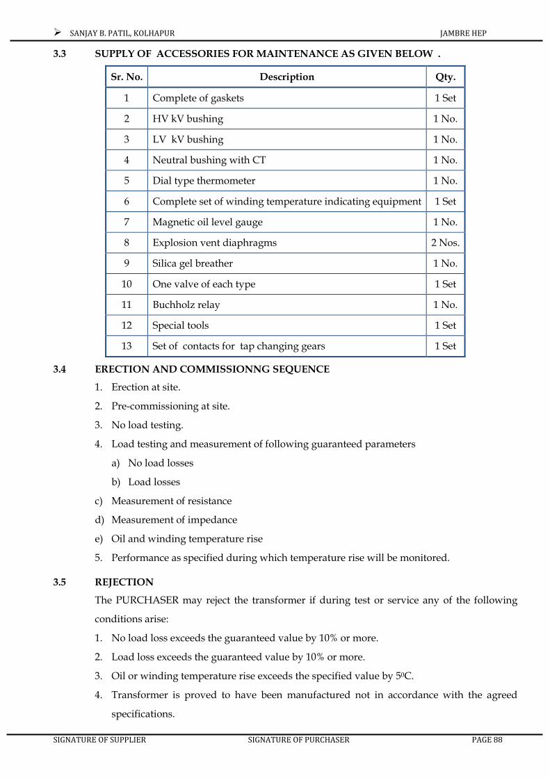
SANJAY B. PATIL, KOLHAPUR JAMBRE HEP
SIGNATURE OF SUPPLIER SIGNATURE OF PURCHASER PAGE 88
3.3 SUPPLY OF ACCESSORIES FOR MAINTENANCE AS GIVEN BELOW .
Sr. No. Description Qty.
1 Complete of gaskets 1 Set
2 HV kV bushing 1 No.
3 LV kV bushing 1 No.
4 Neutral bushing with CT 1 No.
5 Dial type thermometer 1 No.
6 Complete set of winding temperature indicating equipment 1 Set
7 Magnetic oil level gauge 1 No.
8 Explosion vent diaphragms 2 Nos.
9 Silica gel breather 1 No.
10 One valve of each type 1 Set
11 Buchholz relay 1 No.
12 Special tools 1 Set
13 Set of contacts for tap changing gears 1 Set
3.4 ERECTION AND COMMISSIONNG SEQUENCE
1. Erection at site.
2. Pre-commissioning at site.
3. No load testing.
4. Load testing and measurement of following guaranteed parameters
a) No load losses
b) Load losses
c) Measurement of resistance
d) Measurement of impedance
e) Oil and winding temperature rise
5. Performance as specified during which temperature rise will be monitored.
3.5 REJECTION
The PURCHASER may reject the transformer if during test or service any of the following
conditions arise:
1. No load loss exceeds the guaranteed value by 10% or more.
2. Load loss exceeds the guaranteed value by 10% or more.
3. Oil or winding temperature rise exceeds the specified value by 50C.
4. Transformer is proved to have been manufactured not in accordance with the agreed
specifications.

SANJAY B. PATIL, KOLHAPUR JAMBRE HEP
SIGNATURE OF SUPPLIER SIGNATURE OF PURCHASER PAGE 89
5. The PURCHASER reserves the right to retain the rejected transformer and take it into
service until the tenderer replaces, at no extra cost to the PURCHASER, the defective
transformer by a new transformer.
6. Alternatively, the tenderer shall repair or replace the transformer within a reasonable
period to the Purchaser’s satisfaction at no extra cost to the PURCHASER.
3.6 GENERAL CONSTRUCTIONAL FEATURES
1. The transformer and accessories shall be designed to facilitate easy operation, inspection,
maintenance and repairs. Transformer shall also be designed to ensure satisfactory
operation under sudden variations of load and voltage, which may be met with under
working conditions on the system, including those due to short circuit.
2. The design shall incorporate every reasonable precaution and provision for the safety of
all those concerned in the operation and maintenance of the equipment keeping in view
the requirements of Indian Electricity Rules.
3. All material used shall be of the best quality and class most suitable for working under
conditions specified and shall withstand the variations of temperature and atmospheric
conditions arising under working conditions without undue distortion or deterioration of
the setting up of in due stresses in any part and also without affecting the strength and
suitability of the various parts of the work which they are liable to perform.
4. Corresponding parts liable to replacement shall be interchangeable.
5. Cost iron shall not be used for chambers of oil filled apparatus or any part of the
equipment, which is in tension or subject to impact stresses. All outdoor equipment,
including bushing insulator with their mountings shall be designed so as to avoid pocket
in which water can collect.
6. Facility shall be provided for easy lubrication of all bearings and mechanisms.
7. All mechanism shall, where necessary, be constructed of stainless steel, brass or gunmetal
to prevent sticking due to rust or corrosion.
8. All taper pins used in any mechanism shall be of the split type complying with IS 2393.
9. Steel bolts and nuts exposed to atmosphere shall be galvanized.
3.7 GALVANISING
i) Galvanizing where specified shall be done by hot dip galvanizing process or by Electro-
galvanizing process for all parts other than steel wires. The thickness of zinc coating shall
be equivalent to not less than 610 gm of zinc per square meter of surface. The zinc coating
shall be smooth, clean and of uniform thickness and free from defects. The quality of
galvanizing will be established by tests as per IS 2633.

SANJAY B. PATIL, KOLHAPUR JAMBRE HEP
SIGNATURE OF SUPPLIER SIGNATURE OF PURCHASER PAGE 90
ii) All drilling, punching, cutting, bending and welding of parts shall be completed and all
burns shall be removed before the galvanizing process is applied.
iii) Galvanizing of wires shall be applied by the hot dipped process and shall meet the
requirements of relevant Indian Standard. The zinc coating shall be smooth, clean and of
uniform thickness and free from defects.
iv) Surfaces, which are in contact with oil shall not be galvanised or cadmium plated.
3.8 LABELS
i) Labels shall be provided for all apparatus such as relays, switches, fuses, contained in any
cubicle or marshalling box.
ii) Descriptive labels for mounting inside marshalling box shall be of material that will
ensure performance of the lettering. A matter satin finish shall be provided to avoid
dazzle from reflected light. Labels mounted on dark surfaces shall have white lettering on
a black background Danger notices shall have red lettering on a white background.
iii) All plates shall be of incredible material.
iv) Labels shall be attached with brass screws or with steel screws which have received rust
preventive treatment.
3.9 BOLTS AND NUTS
i) Steel bolts and nuts exposed to atmosphere with suitable finishes shall be used like
cadmium plated or zinc plated passivity shall be used for diameters above 6 mm.
ii) All nuts, bolts and pins shall be locked in position with the exception of those external to
the transformer.
iii) If bolts and nuts are placed so that they are in accessible by means of ordinary spanners,
suitable special spanners shall be provided by the contractor. All bolts, nuts and washers
in contact with non-ferrous parts which carry current, shall be of phosphor bronze, where
the transfer of current is though the bolts.
3.10 CLEANING AND PAINTING
i) Before painting or filling with oil or compound, all ungalvanized parts shall be
completely clean and free from rust, scale and grease and all external surface cavities on
castings shall be filled by metal deposition
ii) The interior of the transformer tanks, other oil shall be cleaned of all scale and rust by
sandblasting or other approved method. These surfaces shall be painted with coats of
insulating and hot oil resisting varnish or enamel.

SANJAY B. PATIL, KOLHAPUR JAMBRE HEP
SIGNATURE OF SUPPLIER SIGNATURE OF PURCHASER PAGE 91
iii) Expect for nuts, bolts and washers, which may have to be removed for maintenance
purpose, all external surfaces shall receive a minimum of three coats of paint.
iv) The primary coat of zinc chrome shall be applied immediately after cleaning. The second
coat shall be of an oil and weather nature and of a shade of colour easily distinguishable
from the primary, and final coats shall be applied after the primary coat has been touched
up where necessary. The final coat shall be of glossy oil and whether resisting non fading
paint of shade No.631 of IS 5, primer paint shall be readymade zinc chrome as per IS 104,
intermediate and final coats of a paint shall be as per IS 2932. The paint shall be suitable to
withstand tropical heat and extreme of whether. The paint shall not scale off or crinkle or
be removed by abrasion due to normal handing.
v) Nuts, bolts and washers which may have to be removed for maintenance purposes shall
receive minimum of one coat of paint after erection.
vi) All interior surface of mechanism chambers and marshalling boxes except those which
have received anticorrosion treatment shall receive three coats of paint applied to the
thoroughly cleaned metal surface. The final coat be of a light coloured anti-condensation
mixture.
vii) Any damage to paint work, incurred during transport and erection shall be made good by
the contractor by thoroughly cleaning the damaged portion and applying the full number
of coats of paint that had been applied before the damage was caused. One cost of
additional paint shall be given at site after erection testing and commissioning.
3.11 OIL The transformers and all associated oil filled equipments shall be supplied along with the first
filling of oil and 10% excess quantity of oil for each transformer in non-returnable steel
drums. The filling of the transformer oil shall be done under vacuum. Oil shall be as specified
in IS 335, it shall be free from moisture and have uniform quality throughout and must be
from one lot including spare oil also.
3.12 REVENTION OF ACIDITY The design and all materials and process used in the construction of the transformers shall
such as to reduce to a minimum the risk of the development of acidity in the oil. Special
measure, such as nitrogen selling or the use of inhibited oil shall not be resorted to.
3.13 ELECTRICAL CHARACTERSITICS AND PERFORMANCE
3.13.1 TYPE OF TRANSFORMERS AND OPERATING CONDITIONS
i) Transformers shall be oil immersed and may be core type suitable for outdoor
installation. Transformers shall be provided with conservator vessels.
The type as cooling shall be “ONAN” type.

SANJAY B. PATIL, KOLHAPUR JAMBRE HEP
SIGNATURE OF SUPPLIER SIGNATURE OF PURCHASER PAGE 92
ii) Transformers shall be capable of remaining in operation at full load for continuous
operation without winding hot spot temperature exceeding 1150C. The Contractor shall
give the information regarding the sustained load which can be carried with failure of
cooling system.
3.13.2 CONTINEOUS MAXIMUM RATINGS AND OVERLOADS
i) The transformer shall meet the temperature rise limit specified in IS 2026 on all tapings on
which the rated current is not more than 95% of the maximum rated current on the lowest
voltage tapping. On the other tapping they shall operated continuously without injurious
heating. Loading of transformer shall be in accordance with IS 6600 “guide for loading of
all immersed transformer”.
ii) The transformer shall operate without danger on any particular tapping at the rated KVA
provided that the voltage does not very by more than + -10% of the voltage
corresponding to the tapping.
iii) The transformer shall operate safely at rated output on any tap of the tapping range
specified. Transformer shall be capable of continuous operation at rated load upto 47.5Hz
frequency without exceeding permissible temperature rise.
3.13.3 ELECTRICAL CONNECTION
Transformers shall be connected in accordance with the IS vector symbol YnD 11. High
voltage side as star.
3.13.4 DUTY UNDER FAULT CONDITIONS
i) All transformers shall be capable of withstanding according to IS 2026 without damage
due to any external short circuit between phase, phase to earth, symmetrical /
asymmetrical or any other severity.
ii) Transformers shall under exceptional circumstances due to sudden disconnection of the
load be capable operating at a voltage approximately of 30% above normal rated voltage
for a period of not exceeding one minute and 40% above normal for a period of 5 seconds.
3.13.5 PENALTY FOR EXCESS LOSSES:
The measured losses shall be completed with the guaranteed losses stated in the tender. The
transformer will be accepted only when the measured losses are within permissible limits of
the tolerance (As per IS : 2026 (Part I) 1977 with upto date amendment if any) over the
guaranteed figure stated in the tender subject to the following conditions.
For the excess losses with the range of permissible limit, the price of transformers shall be
reduced at the rate Rs. 120000/= per kW for difference in losses including both no load and
load losses. Cost of losses shall be taken to determine the contract price. If the measured

SANJAY B. PATIL, KOLHAPUR JAMBRE HEP
SIGNATURE OF SUPPLIER SIGNATURE OF PURCHASER PAGE 93
losses exceeds, the guaranteed loss plus the permissible tolerance limits as per IS : 2026 (Part :
1) then it will be at the desecration of the Client to either accept the transformer or reject the
transformer, in case the transformer is accepted the rates of penalty shall be double than those
stated above .
3.13.6 REGULATION AND IMPEDANCE
i) The value of impedance voltage for the transformer at rated current shall be of the order
of 10%.
ii) The value of impedance on any other lapping shall be generally subject, to the approval of
the purchaser. Impedance values on all other tapping shall be stated in the tender.
3.13.7 VIBRATION AND NOISE
Every care shall be taken to ensure that the design manufacture of transformer and auxiliary plant
shall be such that the noise level shall not be more than 5 db above the NEMA standard
publication TR-1.
3.13.8 SUPPRESSION OF HARMONICS
The transformers shall be changed with particular attention to be Suppression of harmonic
voltage, specially the third and fifth, so as to eliminate waveform distortion and any
possibility of high frequency disturbances, inductive effects or of circulating currents between
the neutral points at different transforming stations reaching such a magnitude as to cause
interference with communication circuits.
3.14 CORES
The cores shall be constructed from high grade cold rolled non-aging oriented silicon steel
lamination of low hysterics/loss and high permeability. The design of the magnetic circuit
and the Mechanical constructions of the core assembly of the transformer shall be such as to
avoid vibrations of transformers when it is loaded.
3.14.1 MAGNETIC CIRCUIT
i) The design of the magnetic circuit shall be such as to avoid static discharges, development
of short circuit paths within itself or to the earthed clamping structure and the production
of flux components at right angles to the plane of the laminations which may cause local
heating.
ii) Every care shall be exercised in the selection, treatment and handling of core steel to
ensure that as for as is practicable, the laminations are flat and the finally assembled core
is free from distortion.
iii) Each lamination shall be insulated with a material that will not deteriorate due to
pressure and action of hot oil. Insulating material for core laminations shall not

SANJAY B. PATIL, KOLHAPUR JAMBRE HEP
SIGNATURE OF SUPPLIER SIGNATURE OF PURCHASER PAGE 94
disintegrate due to core vibrations and also due to presence of moisture in a humid and
selling atmosphere, while the material is in transit from tender’s works to the work spot at
site. Paper insulation shall not be used.
iv) Oil ducts shall be provided where necessary to ensure adequate cooling. The winding
structure and major insulation shall not obstruct the free flow of oil through such ducts.
Where the magnetic circuit is divided into pockets by cooling ducts parallel to the planes
of the laminations or by insulating material above 0.25 mm thick. Tinned copper strip
bridging piece shall be inserted to maintain electrical continuity between pockets.
v) The frame work clamping arrangements shall be earthed. Adequate lifting lugs shall be
provided to enable core and winding to be lifted.
vi) The insulation structure for the core to bolts and core to clamp plates shall be such as to
withstand a voltage of 2000 V, 50 cycles AC for one minute.
vii) The magnetic inductance with normal voltage and frequency shall be according to the
latest design practice for the type of steel laminations used and shall be mentioned in the
tender.
The tender shall state the flux density and magnetizing current that would be obtained when working
at normal and 110% normal voltage. The basic volt-amperes required for 110 percent of
maximum flux density and for maximum working flux density at rated voltages shall be
stated in the tender. Contractor shall also state the means adopted in the designs of core for
restricting volt amperes. Turns corresponding to110 percent of flux density on magnetization
curve to a safe value. Contract shall provided over fluxing equipment or it necessary state or
the reasons for not necessity.
3.14.2 MECHANICAL CONSTRUCTION OF CORES
i) All parts of the cores shall be of robust design, capable of withstanding any shock to
which they may be subjected during lifting, transport, installation and service.
ii) All steel sections used for supporting the core shall be thoroughly shot blasted after
cutting, drilling and welding. Any non-magnetic of high resistance alloy shall be of
established quality.
iii) Adequate provision shall be made to prevent movement of the core and winding relative
to the tank during transport and installation while in service.
iv) The supporting frame work of the cores, shall be as designed, as to avoid the presence of
packets, which would prevent complete emptying of the tanks through the drain valves
or cause trapping of air during filling.

SANJAY B. PATIL, KOLHAPUR JAMBRE HEP
SIGNATURE OF SUPPLIER SIGNATURE OF PURCHASER PAGE 95
v) The assembled cores shall be secured by clamps on the limbs and the yoke, so as to
prevent undue noise or vibration against mechanical displacement. The core legs shall be
securely held by means of through bolts adequately insulated. The class and type of
insulation used on the core bolts and under the nuts and side plates shall be stated in the
guaranteed particulars. The use of organic tape or pressed board wrapping to hold the
laminations will not be accepted. All clamping structure shall have adequate mechanical
strength for this purpose and No.1 element in clamping structure shall have permanent
deformation. Clamping structure shall be as so constructed that eddy currents will be
minimized. The insulation and other materials used in construction of cores shall have
been in successful use for at least five years. The clamping shall be firm to reduce
vibrations and to keep noise level within limits.
vi) Core laminations shall be free from all burs and sharp projections.
vii) All structural members of the a smelled cores shall be of steel. All coatings shall be felted
and structural steel adequately cleaned and painted before being built into the structure.
Any non-magnetic or high resistance alloy used shall be of established quality.
viii) The cores shall be connected to the tank by a metal to drawing off Electric static potential.
ix) The maximum hot spot temperature in the cores shall be non injurious to the insulation
and the materials of the core and clamping frame works.
x) Adequate figments shall be provided to enable the cores and the winding to be lifted.
3.15 WINDINGS
3.15.1 GENERAL
1) Star connected H.V. windings shall have graded insulations as defined in IS 2026. The
neutral point shall be insulated for the voltage specified in IS 2026.
2) Transformers shall be designed to withstand impulse and power & frequency test
voltages as specified in IS 2026. The impulse strength of the winding shall not less than
the following basic insulation level of the power system. High voltage winding 650 kV
peak. Low voltage winding 95 kV peak.
3) Further the transformers shall withstand the power frequency test voltage as follows:
4) High voltage winding 70 kV rms
5) Low voltage winding 20 kV rms
6) The contractor shall state the impulse strength guaranteed by him in the schedule-1.
7) The windings shall be designed to reduce to a minimum the out of balance forces in the
transformer at all voltage ratio.

SANJAY B. PATIL, KOLHAPUR JAMBRE HEP
SIGNATURE OF SUPPLIER SIGNATURE OF PURCHASER PAGE 96
8) The insulation of transformer windings and connection shall be free from insulating
composition liable to soften, coze out, shrink or collapse during transport, handling and
service and be non-cattle tic and chemically inactive in transformer oil during transport,
handling and service.
9) The stacks of windings shall receive adequate shrinkage treatment before final assembly.
Adjustable devices shall be provided for taking up an possible shrinkage of coils in
service. All similar coils shall be interchangeable.
10) Oil circulation ducts shall be provided to ensure uniform temperature gradients and the
absence of hot spots. The clamping arrangements and the finished dimensions of any ol
ducts circulation of oil through the ducts.
11) No strip conductor would on edge shall have a width exceeding six times its thickness.
12) The conductors shall be transposed at sufficient intervals in order to minimize eddy
currents and equalize the distribution of currents and temperature along the windings.
13) Windings shall be of electrolytic tinned copper conductors. Class “A” insulation shall be
used electrical and magnetic balance under all conditions of operation. Each of the coils
shall be would of insulated continuous smooth tinned copper conductor of more than
99.9% purity. Wood insulation shall a be treated seasoned.
14) High voltage winding shall have graded insulation. They shall be of the shielded layer
type to ensure uniform voltage distribution under impulse conditions.
15) Special attention shall be given to the provision of adequate insulation and clearance
between the primary and secondary windings. All clearances of windings and other live
parts shall be adequate for the maximum voltage of operation plus 10%. The minimum
clearance adopted shall be stated in the tender. The current densities in primary and
secondary windings shall be given in the tender.
16) All leads from the windings to the terminal boards and bushing shall be rigidly
supported to prevent injury from vibrations.
17) The completed coil and core assembly shall be dried in vacuum thoroughly shrunk to
final dimension and shall be immediately impregnated with oil after the drying process to
ensure the elimination of air and moisture within the isolating structures. Full details, of
drying and vacuum treatment shall be furnished by the tenderer in the tender. The
insulation resistance measured immediately, after impregnation and the temperature at
which it is measured shall be reported for purchaser’s record. All bushings with windings
after assembly must withstand full vacuum, at site inclusive of all assemblies, gaskets
H.T. / L.T. Terminals etc.

SANJAY B. PATIL, KOLHAPUR JAMBRE HEP
SIGNATURE OF SUPPLIER SIGNATURE OF PURCHASER PAGE 97
18) Final filling of the transformer with oil shall be done under vacuum. The procedure to be
adopted shall be furnished in the tender.
3.15.2 BRACING OF WINDINGS
i) The windings connections of all transformers shall be braced to withstand shocks which
may occur during transport, or due to switching, short circuit and other transient
conditions, during services.
ii) Coil clamping rings, if provided, shall be of insulated steel or of suitable insulating
material, Axially laminated material other than Bakelite paper shall not be unsaid.
iii) The neutral of H.V. winding shall be brought out to separately insulation terminal and
shall be effectively connected to the earth.
3.16 INTERNAL EARTHING ARRANGEMENT
3.16.1 GENERAL
All metal parts of the transformers with the exception of the individual core laminations, core bolts,
end associated individual clamping plats, shall be maintained at some fixed potential.
3.16.2 EARTHING OF CORE CLAMPING STRUCTURE
The top main core clamping structure shall be connected to the tank body by a copper strap. The
bottom clamping structure shall be earthed by one or more of the following methods.
a) By connection through vertical tie – rods to the top structure.
b) By direct metal to metal contact with the tank base maintained by the weight of the core
and windings.
c) By a connection to the top structure on the same side or the core as the main earth
connection to the tank.
3.16.3 EARTHING OF MAGNETIC CIRCUIT
i) The magnetic circuit shall be earthed to the clamping structure at one point only through.
ii) Magnetic circuits having an insulated sectional construction shall be provided with a
separate link for each individual section. Where oil ducts or insulating barriers paroled to
the plane of the laminations devoid the magnetic parts, ducts or barriers, shall be bridged
in accidence with clause and the magnetic circuit shall not be regarded as being of
sections construction.
3.16.4 EARTHING OF COIL CLAMPING RINGS
Where coil clamping rings are of metal at earth potential, each ring shall be connected to the
adjacent core clamping structure on the same side of transformers, as the main earth
connection.

SANJAY B. PATIL, KOLHAPUR JAMBRE HEP
SIGNATURE OF SUPPLIER SIGNATURE OF PURCHASER PAGE 98
3.16.5 SIZE OF EARTH CONNECTIONS
All earthing connection with the exception of those form the individual coil clamping rings
shall have a cross sectional area of not less than 0.8 sq.mm. connections inserted between
laminations of different section of core shall have cross sectional area of not less than 0.2
sq.mm.
3.17 TANKS
3.17.1 TANK CONSTRUCTION
1) The tanks shall complete with all accessories and shall be designed so as to allow the
complete transformers in the tanks and filled with oil, to be lifted by crane or jacks,
transported by road, without over straining any joints and without causing subset leakage
of oil.
2) The main tank body of each transformer including tap changing compartments and
radiator shall be capable of withstanding vacuum gauge pressure of (98.5 KN/m2) 740
mm of Hg. However the tank designed for full vacuum shall be tested at on internal
pressure of 3.33 KN m2 (25 mm of Hg.) for one hour. Permanent deflection of flat plate
after the vacuum specified in CBIP specification without effecting the performance of
transformer.
3) The base of each tank shall be so designed that it shall be passable to move the complete
transformer unit by skidding in any direction, without injure when using plates of rails.
4) Where the base is of a channel construction, it shall be designed to prevent retention of
water.
5) Tank stiffeners shall be designed to prevent retention of water.
6) Wherever possible the transformer tanks and its accessories shall be designed without
pocket wherein gas may collect. Where pockets can not be avoided, pipes shall be
provided to vent the gas into the main expansion pipe. The vent pipes shall have a
minimum inside diameter of 20mm except of for short branch pipes which may be 6 mm
minimum inside diameter.
7) All joints other than those which may have to broken shall be welded.
8) The tank shall be fabricated from commercial quality steel plates confirming to IS 226 and
with law carbon content suitable for welding and property reinforced. The finished
materials shall be free from excessive segregation of impurities, cracks, surface flaws,
laminations, rough jagged imperfect edges and all other harmful defects. The tenderer
shall not accept or make use of the plates and reinforcement which are hammer dressed,
patched or wherein welding of defects has been done. All seams shall be welded and

SANJAY B. PATIL, KOLHAPUR JAMBRE HEP
SIGNATURE OF SUPPLIER SIGNATURE OF PURCHASER PAGE 99
where practicable seems shall be double welded. No distortion of joints shall occur while
in service.
9) In addition to vacuum testing as per clause 8.12.1 the tank shall also be tested with oil to
the static head plus 0.35 Kg/Sq.Cm.
10) Compressible gaskets if used shall have metallic stops to prevent over compression.
11) Guide within the tanks or other satisfactory means shall be provided for directing the core
and coil as they are being lowered into or removed from the tank.
12) Ample space shall be provided above the tank bottom for collection of sediment.
13) Lugs and bosses shall be provided for lifting the transformers complete with oil. Pulling
lugs on all sides in the under frame shall be provided at suitable height for handling the
transformer in any direction.
14) Two ground pads capable of carrying for 4 seconds, the full lower voltage short circuit
current of the transformer with bolting arrangements for M.S. earthing strain shall be
welded to the transformer tanks of bases.
15) Ground pads shall be near the base of the transformer about 1.5 m above ground level
and welded to one corner of the opposite tank sides. The pads shall be completed with
threaded holes with nuts bolts etc. The tenderer shall supply complete earthing materials
which shall have to earth the transformer and accessories according to IS code practice.
16) One No. ladder for each transformer shall be provided to ascend the top of transformer
tank. The ladder shall be tubular Aluminum detachable type fitted with clamps to the
tank.
17) A minimum four jacking pads in accessible position to enable the transformer complete
with oil to be raised or lowered using hydraulic jacks. The minimum height of the lugs
above the base shall be 500 mm suitable haulage hole shall be provided.
3.17.2 TANK COVER
1) The tank cover shall be of adequate strength and shall not distort when lifted. Inspection
opening shall be provided as necessary to give easy access to bushings or changing ratio
or testing the earth connection. Each inspection opening shall of ample size for the
purpose for which it is provided and at least two openings, one at each and of the tank
shall be provided.
2) The tank cover and inspection covers shall be provided with suitable lifting
arrangements. The inspection covers shall not weight more than 25 kg. each.

SANJAY B. PATIL, KOLHAPUR JAMBRE HEP
SIGNATURE OF SUPPLIER SIGNATURE OF PURCHASER PAGE 100
3) The tank covers shall be fitted with pockets for a thermometer and for the bulbs of oil and
winding temperature indicators. Protection shall be provided for each capillary tube.
4) The thermometer pocket shall be fitted with a captive screwed for to prevent the ingress
of water.
5) The pockets shall be located in the position of maximum oil temperature at C.N.R. and it
shall be possible to remove the instrument bulbs without lowering the oil in the tank.
6) The tank covers shall be bolted on the flanged rim of tanks with waterproof hot oil
resistant and resilient gasket, for oil tightness. If gasket is compressible, metallic stops.
Shall be provided in the cover to prevent over compression and to facilities unseating of
Cover of the tanks with minimum damage to gasket.
7) Special covers required for shipping shall be supplied by the tenderer on returnable basis
after successful commissioning of transformers.
3.18 UNDER CARRIAGE
i) The transformer tanks shall be fitted with suitable under carriage.
ii) Under carriage for transformers shall be provided with wheels and the axis shall be of
such dimensions and so supported that under any service conditions they shall not deflect
to interfere with the movement of the transformers. Suitable locking arrangement parallel
to and at right angles to longitudinal axis of the tanks shall be provided to prevent the
accidental movement of the transformer in the event of horizontal and vertical force
coming in to play due to earth quake.
iii) The Wheels Shall Have Ball/Roller Bearings
iv) The wheels shall be provided suitable for use of gauge track set at 5’-6” (1676 mm and
shall be so placed that pinch bar can be used to move the transformers. The purchaser will
provide two rails at 1676 mm (5’ – 6”) gauge. Therefore the Contractor shall provide
wheels suitable for use on two rail tracks set at gauge 1767 mm (5’-6”) 90 lbs. rail
sufficient length are available with department and same would be used. Wheels shall be
of bi-directional type.
3.19 CONSERVATOR VESSELS
A vacuum proof diaphragm type conservator with inert gas mounted on tanks shall be
provided. The conservator shall/be provided in such a position as not to obstruct the
electrical connections to the transformers and shall have sufficient capacity between highest
and lowest visible levels to meet the requirement of expansion of the total cold oil volume in
the transformer and cooling equipment.

SANJAY B. PATIL, KOLHAPUR JAMBRE HEP
SIGNATURE OF SUPPLIER SIGNATURE OF PURCHASER PAGE 101
Complete supporting frame of galvanized steel structure shall be provided for the
conservator. Supporting frame shall be designed to take the full load of the conservator with
oil filled upto its maximum level. It shall be possible to take out the transformer fitting and
accessories to be provided below the conservator without fouling with conservator supports
of conservator itself.
1) The oil conservators for the cable sealing chamber shall be complete with feed pipe, read
type buchholz relay with alarm and trip contacts, drain valve, magnetic type oil level with
alarm, bottom and top isolating valves, in the feed pipe on either side of buchholz relay.
2) MAIN OIL CONSERVATOR
i. The minimum indicated oil level shall be with the feed pipe from the main tank covered
with not less than 15 mm depth of oil and the indicated range of oil level shall be from
minimum to maximum.
ii. If the sump is formed by extending the feed pipe inside the conservator vessel. This
extension shall be for at least 75 mm. The conservator shall be designed so that it can be
completely drained by means of the drain valve provided, when mounted as in service. A
filter valve t top shall be provide, for filling the conservator.
iii. Arrangement shall be provided to clean the conservator.
iv. One oil gauge magnetic type with alarm contact shall be provided.
v. The oil level at 30 0C shall be marked on the gauge.
vi. Taps or valves shall not be fitted to oil gauge.
vii. The oil connection from the transformer tanks to the conservator vessels shall be arranged
at a rising angle of 3 to 7 degrees to the horizontal and shall consist of 80 mm inside
diameter pipe as per IS 3630.
viii. A valve shall be provided at conservator to cutout the oil supply to the transformer after
providing a straight run of the pipe or at least a length of 5 times. The internal dia of pipe
on the tank side of buchholz’s relay and at least three times the internal dia of the pipe on
the conservator side of the bush’s relay.
ix. Conservator vessels shall be fitted with a breather for main conservator and the
conservator compartment in which silica gel is the dehydrating agent and designed to
that:-
a) The passage of air is though the silica gel.
b) The external atmosphere is not continuously in contact with silica gel.

SANJAY B. PATIL, KOLHAPUR JAMBRE HEP
SIGNATURE OF SUPPLIER SIGNATURE OF PURCHASER PAGE 102
c) The moisture absorption indicated by a change in colour of the tinted crystal can be easily
observed from distance.
d) All breathers shall be mounted at approximately 1,400 mm above ground level.
e) Caps shall be provided for filling and draining valves.
3.20 FILTER AND DRAIN VALVES SAMPLING DEVICES AND AIR RELEASE PLUGS
i) Each transformer shall be fitted with the following:
a) Two Nos. filter valves of size 50 mm shall be provided one on the top and the other at
bottom of the tank mounted diagonally opposite to each other for connection to oil
circulating equipments. The bottom filter valves shall be flanged to seat 1 ½” B.S.P. male
threaded adopted for filter pipe connection so fitted as to drain off oil completely. Four
Nos. oil inlet and outlet valves between cooling plant and transformer.
b) A drain valve of size 25 mm shall be fitted to each conservator.
c) A robust oil sampling device shall be provided at the top and bottom of the main tank.
The sampling device shall not be fitted on the filter valves specified under (a) above.
d) One 15 mm air release plug.
e) Drain valve of size 100 mm with cap of main transformer.
ii) All other valves opening to atmospheres shall be fitted with blank flanges.
3.21 PRESSURE RELIF DEVICE
i) The pressure relief device shall be provided of sufficient size for rapid release of any
pressure that may be generated within the tank, and which might result in damage to the
equipment. The device shall operate at a static pressure of less than the hydraulics test
pressure for transformer tank means shall be provided to prevent the ingress of water.
ii) The relief device shall be mounted on the main tank and if on the cover, shall be fitted
with skirt projecting 25 mm inside the tank and of such a design to prevent gas
accumulations.
iii) If a diaphragm is used, it shall be of suitable design and materials and situated above
maximum oil level.
iv) An equalizer pipe connecting the pressure relief device to the conservator shall be
provided for relieving or equalizing the pressure in the pressure relief device.
v) The fitting of silica gel breather to the pressure relief device, the breather being mounted
in a suitable position for access at ground level.

SANJAY B. PATIL, KOLHAPUR JAMBRE HEP
SIGNATURE OF SUPPLIER SIGNATURE OF PURCHASER PAGE 103
3.22 ACCOMODATION FOR AUXILIARY APPARATUS
The contractor shall provide supporting frame work insulators, copper conductor/strip,
clamps for formation of H.V. neutral and earthing of neutral, current transformer and its
enclosure on transformer body itself.
3.23 RATING AND DIAGRAM AND PROPERTY PLATE
The following plates shall be fixed to the transformer tank at an average height of about 1500
mm above ground level.
a) A rating plate bearing the date specified in the appropriate clause of IS 2026.
b) A diagram plate showing the internal connections and also the voltage vector relationship
of the several windings in accordance with IS 2026 and in addition, a plan view of the
transformers giving the correct physical relationship of the terminals. Approved means
shall be provided for clearly indication ratio for which the transformers are connected. No
load voltage shall be indicated for each top. All valves shall be provided with table
showing the function of valves.
c) A plate showing the location and functions of all valves and air release cocks or plugs
shall be provided. This plate shall also warn operator to refer to the maintenance
instruction before applying vacuum, treatment for drying.
3.24 RADIATOR CONNECTION
Valves and valves mounting shall be provided as specified under following clause.
They shall be full way time with internal screw and shall be opening by running counter
clockwise when facing the hand wheel.
Means shall be provided for pad locking the bottom valves in the open and closed positions.
This is required for the valves where opening device like hand of wheel, keys etc., are the
integral part.
All valves except radiator valves shall be of gunmetal. The radiator valve shall be of cost iron
plate type.
Every valve shall be provided with an indicator to show clearly the position of valve.
All valves shall be provided with flanges having machined faces.
The drilling of valve flanges shall be comply with the requirement of IS 3639.
3.25 COOLING
The transformer shall be provided with oil natural air natural (ONAN) type of cooling system
to give, the darted output at rated voltage and frequency without exceeding the limits of
temperature rise as specified in IS – 2026/1972.

SANJAY B. PATIL, KOLHAPUR JAMBRE HEP
SIGNATURE OF SUPPLIER SIGNATURE OF PURCHASER PAGE 104
The radiators shall be designed to withstand safely the pressure conditions specified for the
tank and shall be free form the defects, such as welding or cracks, impurities in radiator
material etc. the radiators shall be removable for repairs without necessitating the draining of
oil from the transformer. The radiators shall be connected to the tank by machined steel
flanges, bolted to the tank and provided with gaskets. Shut off valves shall be provided for
each radiator, which can be locked either in open or in closed position.
A separate oil tight blank flange shall also be provided for each of the tank connections to
radiator, these will be used when radiators are to be detached.
Each radiator shall have a lifting bye, an oil drain plug of adequate size at the bottom an air
release vent of adequate size at the top.
The radiators shall be so designed that they are accessible for cleaning and painting and to
prevent accumulation of water on the outer surface, and to ensure against formation of gas
pockets when the tank has been filled.
Contractor shall clearly mention in his tender the details regarding radiators, their location,
type, quantity, number of valves, cooling surface, permissible pressure and the various
accessories provided for radiators.
3.26 VOLTAGE CONTROL OFF CIRCUIT TYPE
i) Each transformer shall be provided with a manual off circuit tap changing gear for
varying its effective ratio of transformation while the transformer is de-energized and
without producing phase displacement. The tapping range shall from +5% to –5% in the
steps of2.5%.
ii) The off-circuit switch handle will be provided with a locking arrangement along with tap
position indicator thus enabling the switch to be locked in any tap position. A warning
late indicating hat switch be appeared only when the transformer is de-energined shall be
fitted.
iii) The tap changer shall be connected to the taps on high voltage star connected windings
for +5% and –5% in steps of 2.5%.
iv) A hand wheel or lever with position indicator shall be proved on the high voltages side
for operating the tap changer manually on no load without necessitation removal of the
tank cover of lowering of oil.
v) The mechanism shall be such that it will be impossible to leave a winding open of short
circuited when operating handle is place in a locked position.
vi) It shall be possible to operate the hand wheel or lever for the tap changer from the
transformer base level.

SANJAY B. PATIL, KOLHAPUR JAMBRE HEP
SIGNATURE OF SUPPLIER SIGNATURE OF PURCHASER PAGE 105
3.27 FITTINGS AND ACCESSORIES
Standard fittings, valves, gauges, pulling lugs and instruments of established quality shall be
provided and the tender shall give the complete information necessary for subsequent
replacement of these items. All valves except filter sampling and drain valves openings to
atmosphere shall be fitted with blank flanges. Valves, shall be of gunmetal having integral
opening device, padlocks, position indicators, flanges with machined faces.
1) Diaphragm type conservator with inert gas of sufficient capacity complete with filter
valve and flanges drain valve with caps complete supporting frame work.
2) One magnetic type oil level gauge with low oil level alarm.
3) Dial type oil temperature indicator with maximum pointer and two sets of contacts. The
temperature indicator shall be housed in marshalling box.
4) Dial type winding temperatures indicator one for each L.V. winding with maximum
pointer and two sets of contacts. The temperature indicators shall be hosed in respective
marshalling box.
5) One number silica gel breather with oil seal and connecting pipe.
6) One number read type buchholz relay with alarm and trip contacts, double element
arrangement, isolating valves on higher side.
7) Pressure relief devices for transformers.
8) Pocket on tank cover for thermometers.
9) Explosion vent.
10) VALVES
a) Drain valve of size 100 mm with cap for main transformers.
b) Two numbers oil filter valves of size 50 mm with caps and adopter. One at the bottom
and other at the top of the transformers on diagonally opposite corners.
c) Two numbers oil sampling valves at the top and bottom of the tank.
11) Isolating valves for conservator.
12) Two numbers earthing terminals with nuts, bolts, washers etc., for proper earthing of
transformer tank shall be provided. Earthing terminals similar to above for earthing of
fittings and accessories of the transformer such as marshalling box etc., shall be provided.
Copper strips, lugs, reverts, cleats etc., require for earthing above items with the earth mat
of power house shall also be provided.
13) Rating and diagram plates.

SANJAY B. PATIL, KOLHAPUR JAMBRE HEP
SIGNATURE OF SUPPLIER SIGNATURE OF PURCHASER PAGE 106
14) Valve schedule plate.
15) Jacking pads.
16) Lifting eyes for core frame with windings lifting bollards.
17) Haulage lugs.
18) Cover lifting lugs.
19) Bi-directional double flanged rollers. 5’-6” gauge.
20) Marshalling box.
21) Air release device.
22) Off circuit tap changing gear.
23) Radiators – detachable radiators
24) Inspection opening for the transformers suitably sealed with cover for access to the inner
and end of bushing and the off circuit tap switch.
25) H.V. Neutral bushing, current transformer with enclosure, supports copper conductor,
clamps and support insulators, strain insulators etc.
26) Ladder to ascend to top of the transformer.
27) Cable chamber suitable for connection of L.V. bushing with the end of power cables,
complete with i) Support for chamber, ii) connector with coupling and supports for
connector if any, glands, insulating material etc.
28) a) H.V. busing completely immersed in oil.
b) Neutral bushing for H.V. winding.
c) Neutral current transformer
d) Bushing for L.V. winding
29) Sufficient quantity of oil required for each transformer and all associated oil filled
equipments and extra 10% of the oil required for assembled transformer shall be supplied
in non-returnable steel drums. The oil shall be as specified in IS 335. It shall be as free
from moisture and have uniform quality through out.
30) Four Mechanical screw type jack, each having a capacity of about 33 percent of the total
weight of the transformer with oil shall be provided for the transformer.
The accessories and fittings shall include the wiring from various transformer accessories upto
the marshalling box and this wiring shall be of standard copper 660/1100 volt grade PVC

SANJAY B. PATIL, KOLHAPUR JAMBRE HEP
SIGNATURE OF SUPPLIER SIGNATURE OF PURCHASER PAGE 107
insulated cables as per relevant IS and of appropriate size enclosed in rigid steel conduits
mounted on the tank near the base by means of clamps.
31) OTHER FITTINGS
Such other fittings, which are in line with manufactures standard practice, shall be provided.
Other fittings recommended by the Conductor for satisfactory operation of the transformer
shall also be provided.
32) Special adjustable and rod gaps shall be provided for the 33 kV terminal bushing to
enable to Co-ordination of insulation level with surge diverted. The gap setting shall be
fixed with reference to the impulse strength of 170 kV class winding.
3.28 BUSHING TERMINAL ARRANGEMENT
All bushing shall be suitable for continuous operation at 10% above the nominal voltage of
the bushing. The bushings shall be in accordance with IS 2099 and 3347 and shall be suitable
for the transformer confirming to IS 2026. The clearance between live conductive parts to
earthed structure shall be
1. Phase to phase : 350 mm
2. Phase to earth : 320 mm
The bushing shall have high mechanical strength stable insulation and high puncture value to
ensure on external flash over before a break down occurs due to high voltage, a high factor of
safety against leakage to ground and shall be located as to provide adequate electrical
clearance between bushing and between the bushing and grounded parts. Bushing of
identical voltage rating shall be in for changeable. All bushings shall be equipped with
terminals of approved type and size. All porcelain used in bushing shall be wet process
homogeneous and free from cavities or other flaws. The glazing shall be uniform in colour
and free from bolsters, burns and other defects. Main terminals shall be molder less. The
insulation class of high voltage bushing, low voltage bushing and the high voltage natural
bushing shall be properly co-coordinated with the insulation class of the respective windings.
Any stress shield shall be considered as integral parts of the bushing assembly.
The bushing shall be arranged that it can be removed without disturbing the connections or
pipe work.
Special precautions shall be taken to exclude moisture for paper isolation during
manufactures identification mark and such other mark as may be required to assist in the
representative selection of batches for the purpose of the sample tests.
Clamps and fittings made of steel or malleable iron shall be galvanized. All bolt threads shall
be greased before erection.
The bushing flanges shall not be of reentrant shape which may trap air.

SANJAY B. PATIL, KOLHAPUR JAMBRE HEP
SIGNATURE OF SUPPLIER SIGNATURE OF PURCHASER PAGE 108
Bushing shall be provided with vent pipes which shall be connected to route any gas
collections through the buchholz relay.
The power factor of each bushing shall be measured at the contracts works and test
certificates furnished for approval of purchaser.
The winding side connection terminal of the bushing shall be of the cable type suitable for
brazing on the winding side and screwed on the cap side so that bushing can be removed
without opening the top cover of the transformer by sliding the load down the control
bushing tube.
3.29 H.V.BUSHING AND TERMINAL ARRANGEMENT
H.V. bushing shall be suitable for 33 kV outdoor oil immersed draw through condenser type
transformer H.V. bushing suitable for 36 kV grade per phase shall be provided the top of the
transformer tank so as to facilitate proper connections with bus.
3.30 H.V. NEUTRAL BUSHING
The Contractor shall provide for each transformer one neutral bushing ousted on top of the
tank. The bushing shall be of oil filled porcelain stem type its rated voltage shall be intimated
along with the tender.
The Contractor shall provide the equipment such as copper strip, coupling clamp for neutral
bushing and copper strip cleat/clamps, support insulator etc., for formation and earthing of
neutral. Earthing neutral to the powerhouse earth-mat shall be done by the contractor. Single
core body mounted totally enclosed type neutral current transformer shall be provided for
each transformer of accuracy class 10/1 A-30 A – 10 p – 20.
Formation and earthing arrangement of neutral shall be subjected to the approval of the
Purchaser.
3.31 L.V.BUSHING AND TERMINAL ARRANGEMENT
The Contractor shall provide for each transformer three numbers solid stem type porcelain
bushings mounted on detachable adopter on transformer body suitable for connection with
adequate size single core. XLPE copper cables, complete with coupling clamps etc., Locations
of L.V. bushing arrangement and the type of coupling/clamps shall be provided for cable
trucking around L.V. bushing along with cable terminal arrangement, insulation, and glands
etc.
3.32 TEMPERATURE INDICATING DEVICES AND ALARM
i) The tripping contacts of dial type thermometer for oil temperature indicator and winding
temperature indicators shall be adjustable to close 600C and 1200C and alarm contacts to
class between 900C and 1000C and both shall reopen when the temperature has fallen by
about 10 0C.
ii) All contacts shall be adjustable on a scale and shall be accessible on removal of the cover.

SANJAY B. PATIL, KOLHAPUR JAMBRE HEP
SIGNATURE OF SUPPLIER SIGNATURE OF PURCHASER PAGE 109
iii) The temperature indicators shall be so designed that is shall be possible or check the
operation of the contact and associated equipment.
3.33 BUCHHOLZ RELAY
i) EACH TRANSFORMER shall be fitted with one double float buchholz relays (confirming
to IS 3637) in the feed pipe for transformer tanks. The buchholz relay shall be of read type,
having upper contacts for alarm and lower element for tripping. The Buchholz Relays
provided by the tenderer shall not malapert and shall safely withstand the forces due to
earthquake acceleration suitable for earth quake zone stipulated by ISS for the region. The
design of the equipment which has a frequency i.e. between three cycles per second to 15
cycles per second shall be such as to withstand the earthquake forces of dynamic strength
noted above, taking into considerations the response acceleration due to resonance. The
tenderer shall note that buchholz relays with mercury contact would not be accepted.
ii) Each relay shall be provided with a test cock to take flexible pipe connection for checking
the operation of the relay.
iii) A machined surface shall be provided on the top of each relay to facilitate the setting of
the relays and check the mounting angle in the pipe and the cross level of the relay.
iv) The design of the relay, mounting arrangements associated pipe work and the cooling
plant shall be such that mal-operation of the relays shall not take place under normal
service conditions.
v) The pipe work shall be so arranged that all gas arising from the transformer, shall pass
into the gas and oil actuated relay. The oil circuit through the relay shall not from delivery
path in parallel with any circulating oil pipe nor shall be tied into or connection through
the pressure relief vent, sharp bends in the pipe work shall be avoided.
vi) Adequate clearance between oil pipe work and live metal shall be provided.
3.34 MARSHALLING BOX
i) Tenderer shall provide tank mounted marshalling box for auxiliary apparatus for each
transformer. Each marshalling box shall be flat topped, corrosion resisting, vermin proof,
well ventilated, weather proof, complete with Supports, lifting books, earthing terminals
and with hinged door with padlock arrangement. The marshalling box shall be of sheet
steel construction. The inside of such marshalling box shall be painted with white anti
condensation paint. The base plate shall have suitable opening for cable with necessary
cable glands to plug the holes. Glass windows shall be provided for noting readings of the
dial thermometers etc. As the marshalling kiosk is to be fitted on the transformer met for

SANJAY B. PATIL, KOLHAPUR JAMBRE HEP
SIGNATURE OF SUPPLIER SIGNATURE OF PURCHASER PAGE 110
outdoor installation. Gaskets provided for its door shall be of such type that seals the
kiosk to make it perfectly water proof.
ii) The Contractor shall state in his tender auxiliary A.C. and D.C. power requirement for
each transformers. The Contractor shall prepare cable schedules for the following cables.
1) Cables to be provided and laid by him from the marshalling box to various transformer
accessories and fittings. Cables to be provide by the Purchaser between the marshalling
box of the transformer and the auxiliary power supply panel and transformer control
panel.
A ring of copper connection of 25 mm x 6 mm strop shall be provided in the marshalling box
for its earthing. Suitable connecting bolts for connecting the earthing to the earthmat shall be
provided.
Disposition of controls, indicating instruments in marshalling box shall be subject to the
approval of the Purchaser.
Indicating instruments shall be suitable for working in tropical climatic conditions and shall
comply with relevant IS or BS.
iii) The temperature indicators shall be so mounted that the dials are not more than 1600 mm
from ground level and the doors of adequate size.
iv) To prevent internal condensation, an approved type of metal clad heater, controller by a
thermostat, shall be provided. Ventilation shall be provided.
v) All incoming cables shall enter marshalling box from the bottom and the gland plate shall
be not less than 450 mm from the based of marshalling box. The land plate and associated
compartment shall be sealed in suitable manner to prevent the ingress of moisture from
the cable trench.
vi) Underlined gland plate shall be provided for accommodation gland for incoming and
outgoing cables.
vii) The following equipment shall be housed in each marshalling box.
1) Heater with thermostat control.
2) Auxiliary transformers
3) No. volt contractors for supply failure.
4) Winding temperature indicator with alarm and trip contacts, for L.V. winding.
5) Oil temperature indicator with alarm and trip contacts.

SANJAY B. PATIL, KOLHAPUR JAMBRE HEP
SIGNATURE OF SUPPLIER SIGNATURE OF PURCHASER PAGE 111
6) Illumination lamp 60 W bulb with switch. 15-A3 pin sockets with switch.
7) Alarm and trip contacts for Buchholz relay.
8) Low oil level alarm devices.
9) Terminal block with 20% spare terminals.
10) Fuses and links.
11) Other auxiliary relays, including over load and single phase protection.
12) Danger plate.
13) On-off indication for A.C. & D.C. supply.
14) Isolating switches for the incoming circuits.
3.35 CONTROL CONNECTIONS AND INSTRUMENT WIRING TERMINAL BAORD AND
FUSES
CONTROL INDICATION AND ALARM SCHEME
Transformer control panel the transformers shall have to be provided.
The devices includes under marshalling box shall be supplied by the Contractor. In order to
repeat the function on the transformer control panel in control room, sufficient spare contacts
shall be for control indication and alarm and the same shall be wired upto the terminals strips
in the marshalling boxes.
The Contractor shall provide the schematic diagrams of connections of various alarm and trip
contact. The cabling between the terminal block of the marshalling box and that of the
transformer control panel shall be provided and shall provide the cable schedule indicating
the sizes, cores, type ratings etc., of the cables. These cable schedules shall be furnished by the
Contract along with the contract drawings.
1. All wiring connections, terminal boards, fuses and links be suitable for tropical
atmosphere any wiring liable to be in contact with oil, shall have oil resisting insulation
and the bare ends of standard wire shall sweated together to prevent curettage of oil
along with wire.
2. There shall be no possibility of oil entering in the connection boxes used for cable or
wiring.
3. Marshalling box connections shall be neatly and securely fixed to the marshalling box. All
instruments and box wiring shall be run in PVC or non resting metal cleats of the limited
compression type. All wiring of box shall be taken from suitable terminal boards.

SANJAY B. PATIL, KOLHAPUR JAMBRE HEP
SIGNATURE OF SUPPLIER SIGNATURE OF PURCHASER PAGE 112
4. Where conduits are used, the runs shall be laid with a suitable fails, and the lowest parts
of the run shall be adequately drained and ventilated. Conduit shall not be run at or
below ground level.
5. When 415 volt connections are taken through junction boxes or marshalling box they shall
be adequately screened and 415 volt danger notices must be affixed to the outside of the
junction boxes or marshalling box.
6. The marshalling box wiring shall be in accordance with relevant IS. All wiring shall be
standard copper of 1100 V // 600 V grade PVC insulated cables and size not less than 2.5
sq.mm for connections and 4 sq.mm. for C.T. connector.
7. All wires in marshalling box and all multi core cables shall have ferrules which bear the
same number at both ends.
8. The same ferrule number shall not be used on wires in different circuits on the same box.
9. Ferrules shall be insulating materials and shall be provided with glossy finish to prevent
the adhesion of dirt. They shall be clearly and durably marked in black and shall not be
affected by damp or oil.
10. Standard wires shall be terminated with tinned crimped tabular lugs. Separate lugs shall
be used for each wire. The size of lugs shall be suited to the size of the wire terminated,
separated washer of tinned copper of appropriate sizes shall be provided for each wire
wiring shall in general be accommodated on the disuse of the marshalling box and the
wires for each circuit shall be separately grouped. Back of he marshalling box wiring shall
be arranged so that access to the connections stems of relays and other apparatus is not
impeded.
11. Wires shall not be joined or tied between terminal points.
12. D.C. and A.C. circuit shall be kept physically separated form remaining wiring. The
function of each circuit shall be marked on the associated terminal boards.
13. Wherever apparatus is mounted on panel, all metal cases shall be separately earthed by
means of Cu. wire or strip having the cross section of not less than 2 sq.mm. where strip is
used, the joints shall be sweated.
a. All wiring diagram of control and relay panel shall preferably by drawn as viewed from
the back and shall show the terminal boards arranged as in service. All diagrams shall
show which view is employed.
14. Multicore cable tails shall be so bound that each wire may be traced without difficulty to
its cable.

SANJAY B. PATIL, KOLHAPUR JAMBRE HEP
SIGNATURE OF SUPPLIER SIGNATURE OF PURCHASER PAGE 113
15. The screens of screen pairs of multicore cables shall be earthed at one end of the cable
only. The position of earthing connections shall be shown clearly on the diagrams.
16. All terminal board rows shall be mounted to give easy access of termination and to enable
ferrule numbers of read without difficulty.
17. Terminal boards rows should be spaced adequately not less than 100 mm apart to permit
convenient access to wires and termination.
18. Terminal boards shall be so placed with respect to the cable gland (at a minimum distance
of 200 mm) as to permit satisfactory arrangement of multicore cable tails.
19. Terminal boards shall have pairs of terminals for incoming and outgoing wires. Insulating
barriers shall be provided between adjacent co connections. The height of the barriers and
the spacing between terminals height shall such as to give adequate protection, while
allowing case access to terminals. The terminals shall be adequately protected with
insulating dust proof covers.
20. No line metal shall be exposed at the back of the terminal boards.
21. All fuses shall be of the cartridge type.
22. Fuses and links shall be labeled.
3.36 TESTING AT MANUFACTURERS WORKS AND AT SITE
3.36.1 ROUTINE TEST (AT MANUFACTURER’S WORKS)
i. The following routine tests shall be carried out on the completely assembled transformer
and accessories in the presence, of the representative of purchaser. Oil leakage test being a
routing test shall be carried out on the transformer, in presence of Purchaser
representative.
b. Measurement of winding resistance.
c. Measurement of voltage ratio and check of voltage relationship.
d. Measurement of impedance voltage / short circuit impedance (Principal tapping).
e. Measurement of load loss.
f. Measurement of no load loss and current.
g. Measurement of insulation resistance.
h. Dielectric test specified in IS 2026 (Part III as enumerated below:)
i. Separates source power frequency voltage withstand test.
j. Induced over voltage withstand test.

SANJAY B. PATIL, KOLHAPUR JAMBRE HEP
SIGNATURE OF SUPPLIER SIGNATURE OF PURCHASER PAGE 114
k. Operational tests for off circuit tap changer switch.
l. Tests on insulating oil in accordance with IS : 335/1972.
3.36.2 OIL LEAKAGE TEST ON TANK (AT MANUFACTURER’S WORKS)
The tank and oil filled compartments shall be tested for oil tightness by being completely
filled with oil of a viscosity not greater than that of insulating oil IS : 335 at an ambient
temperature and subjected to a pressure equal to the normal pressure plus 35 KN / M2 12
hours, during which time no leakage shall occur. The test shall be witnessed by Purchaser’s
representative.
3.36.3 TYPE AND SPECIAL TEST (AT MANUFACTURER’S WORKS)
A) The Contractor should furnish type test certificates for impulse voltage withstand test and
temp. rise test, already carried out by the Contractor on similar type / rating of the
transformers along with the tender. If such above said tests are not carried out by the
Contractor earlier and hence the Contractor is unable to furnish the certificates for the
same the Contractor shall have to accept burden at the rate of Rs. 25 Lacs for evaluation
purposes.
B) The following additional type tests on tank shall also be carried out.
• PRESSURE TEST
The transformer tank together with its conservator vessel and other fittings shall be
subjected to pressure corresponding to twice the normal head of oil or to the normal
pressure 35 KN / m2 (5 lb / sq.in) whichever is lower measured at the base of the tanks
and will be maintained for one hour. The tank shall withstand this test pressure without
any abnormality.
• VACUUM TEST
The transformer tank shall be tested for an internal pressure of 3.33 KN / m3 (25 mm of
Hg) for one hour. The permanent deflection of flat plates after the vacuum is released
shall not exceed the values as stipulated in CBIP manual on transformers without
affecting the performance of the transformer.
3.36.4 TEST BEFORE COMMISSIONING (AT SITE)
After erection at site the transformer shall be subjected to the following test:
1) Insulation Resistance.
2) Ratio and Polarity Test
3) Oil test before putting transformer into operation, the oil shall be tested as per IS : 335 /
1372. Instruments and facilities etc., as available at site shall be provided by the Department.

SANJAY B. PATIL, KOLHAPUR JAMBRE HEP
SIGNATURE OF SUPPLIER SIGNATURE OF PURCHASER PAGE 115
However, special measuring instruments, tools, tackles, etc., will have to arranged by the
Contractor at his cost.
3.36.5 GENERAL
All accessories and fittings, radiators, bushings, conservator etc., shall be tested in accordance
with the relevant Indian Standards and where such Standard is not available, as per
manufacturer’s Standard practice.
For the tests specified above, the contractor shall furnish six copies of test certificates for
approval. In addition to above, the Purchaser reserves the right of carrying out at site as such
tests as he may decide upon. The reasonable charges will be mutually agreed upon in that
case.
Any other tests as may be called for by the Purchaser, Contractor shall furnish six copies of
the test certificates for the approval of the Department.
3.37 PROTECTION
It is proposed to provide the following protection for the transformer.
i) Overall Differential protection.
ii) Over current and earth fault protection.
iii) Thermal protection (winding temperature)
iv) Buchholz protection read type relays.
In spite of at above any additional protection equipment which is necessary shall be
provided.
Sr. no. Spare parts for Main Transformer 1 (25/31.5 MVA)
1. Transformer bushing of each type Set 1
2. Sets of contacts for off-load tap-changer Set 10
3. Sets of complete gaskets for one transformer Set 2
4. Pieces of complete dehydrating breather Nos 7
5. Silica gel Kg 20
6. Pressure relief devices Nos 2
7. Complete Buchholz relays of each type Nos 2
8. Fans in complete with motor Nos 2
9. Radiators Set 2
10. Oil level gauges Nos 2
11. Contact thermometers Nos 4
12. Spare for control cabinet Nos each 3
13. Volume of transformer oil % 10
14. 5% of installation bolts Lot 1

SANJAY B. PATIL, KOLHAPUR JAMBRE HEP
SIGNATURE OF SUPPLIER SIGNATURE OF PURCHASER PAGE 116
AUXILIARY TRANSFORMER :
TRANSFORMER:- 100 KVA, 3.3 KV/ 433 V.
UNIT AUXILIARY TRANSFORMER (U. A. T.)
3.1 SCOPE
The work covered under these specifications comprises of one no. 100 K. V. A., 3.3/ 0.433
K.V., 50 Hz, 3 Phase outdoor type distribution transformer complete with fittings of all
accessories and first filling of oil.
3.2 TYPE & RATING
The details regarding the type and rating etc. are as under.
Sr. No. TYPE RATING
1. Particular of specification to be
compiled with indoor or outdoor
type.
: Indoor type.
2. Type of cooling. : ONAN
3. Rated power at principal tappings : 100 KVA
4. Frequency. : 50 Hz.
5. No of phases in the system. : Three Phase
6. Rated Voltage
a) H. V. Winding. : 3300 Volts
b) L. V. Winding. : 433 Volts
7. Details of tappings. : 5 Nos from ±2 % to +5 %
in steps of 2 %.
8. Dry. Type or oil immersed type. : Oil immersed type with
mineral oil.
9. Type of Transformer. : Copper wound.
10. Connection symbol. : D^Yn 11.
11. Highest voltage of equipment
a) H. V. Side. : 7.5 KV RMS. ll-
b) L. V. Side. : 500 Volts.
12 Terminal Details
a) H. V. Side. : Through Cable end box.
b) L. V. Side. : Through cable end box.
13. Fittings. :
14. Axles & wheels : Four bi- directional plain
rollers with locking
arrangement.
SANJAY B. PATIL, KOLHAPUR JAMBRE HEP
SIGNATURE OF SUPPLIER SIGNATURE OF PURCHASER PAGE 117
15. Plinth or pole mounted transformer : Plinth mounted
transformer.
3.3 STANDARDS
Except where specified otherwise, the equipment covered under this specification shall
comply with the following Indian standards including the latest amendments if any, and the
relevant other standards mentioned therein.
1) Distribution transformer. : - IS 2026
2) Insulting oil. : - IS 335
3) Bushings & their accessories. : - IS 2099.
Any other associated equipments material such as core, laminations, winding, insulating
material, cable end box etc. confirming to relevant Indian standards.
3.4 TEMPERATURE RISE: -
The maximum temperature rise in winding and oil, core, metallic parts and Adjacent
materials when the transformer is operating at rated voltage, rated frequency, rated load and
0.866 p. f. lag shall not exceed the limits as specified in IS – 2026 (part II) 1977.
3.5 LOSSES TO BE GUARANTEED : -
The transformer shall be designed such that its iron losses (No load Losses) should be
minimum to the extent possible in considering the total design aspects. The Contractor shall
quote the guaranteed losses as detailed below : -
a) Guaranteed no load loss at rated voltage on principal and rated frequency.
b) Guaranteed full load copper losses at rated current at principal Tappings and 75 o C.
If no load losses observed to be more than the guaranteed no load losses at the time of factory
test the same shall be rejected by the department and no charges/ cost occurring out of such
rejection shall be paid to the contractor by the department. In case losses are more than 4% of
guaranteed value transformer will be rejected. This is applicable for individual transformer.
3.6 DESIGN : -
The transformer and accessories shall be designed to facilitate operation, inspection,
maintenance and repairs. All apparatus shall be designed to ensure satisfactory operation
under such sudden variation of load & voltage as may be met with under working condition
on the system including those due to short circuits.
3.7 PAINTING: -
The interior of transformer tank and other oil filled chamber and internal structure steel work
shall be cleared of all scale and rust by blasting or other approved method. These surface
shall be painted with hot oil resisting varnish or paint.

SANJAY B. PATIL, KOLHAPUR JAMBRE HEP
SIGNATURE OF SUPPLIER SIGNATURE OF PURCHASER PAGE 118
All external surfaces shall receive a minimum of three coats of paints. One coat of additional
paint shall be given at site by contractor.
3.8 OIL : -
The transformer and all associated oil filled equipment shall normally be supplied along with
first filling of oil. The oil shall be free from moisture.
3.9 TYPE OF TRANSFORMER & OPERATION CONTIDION : -
The transformer shall be oil immersed and shall be of core type suitable for outdoor
installation. The cooling shall be ONAN type.
3.10 CONTINUOUS MAXIMUM RATING AND OVER LOADS : -
Transformer shall meet the temperature rise limits specified in I. S. 2026 on all tappings on
which the rated current is more than 95 percent of the maximum rated current on the lowest
voltage tapping.
3.11 ELECTRICAL CONNECTIONS : -
Transformer shall be connected in accordance with the vector symbol – DYn 11.
3.12 DUTY UNDER FAULT CONDITION : -
The transformer shall be capable of withstanding according to IS 2026 without any damage
by any external short circuit between phases.
3.13 VIBRATION & NOISE : -
Every care shall be taken to ensure that the design & manufacture of transformer &
accessories shall be as per the NEMA standard publication TR- 1.
3.14 CORES : -
The core shall be connected from high grade cold rolled non aging oriented silicon steel
laminations.
3.14 MECHANICAL CONSTRUCTION OF CORES : -
All parts of the core shall be of robust design capable of withstanding any shocks to which
they may be subjected during lifting, transporting, installation & service.
3.15 WINDINGS : -
The windings shall be designed to reduce to a minimum the out of balance forces in the
transformer at all voltage ratios.
Windings shall be of electrolytic copper conductors, all permanent current carrying joints in
the windings and leads shall be brazed or soldered as the case may be.

SANJAY B. PATIL, KOLHAPUR JAMBRE HEP
SIGNATURE OF SUPPLIER SIGNATURE OF PURCHASER PAGE 119
The insulation of the transformer windings and connection shall be free from insulating
composition liable to soften, ooze out, shrink or collapse and be non catalytic and chemically
inactive in transformer oil during service.
3.16 INTERNAL EARTHING ARRANGEMENTS : -
All metals parts of the transformer with the exception of the individual core laminations core
bolt and associated clamping plates shall be maintained at some fixed potential.
3.17 TANK : -
The Tank shall be of conventional type construction and shall be fabricated from commercial
quality steel plates.
3.18 LIFTING FACILITIES : -
The tank shall be provided with lifting lugs suitable for lifting the transformer complete with
oil.
3.19 TANK COVER : -
The tank shall be of adequate strength and shall not distort when lifted.
The thermometer pocket shall be fitted with a captive screwed top to prevent the ingress of
water.
Ample space shall be provided at the tank bottom for collection of sediments.
3.20 AXLES AND WHEELS : -
The transformer shall be provided with the wheels and axles of such dimensions and so
supported that under any service conditions they shall not deflect sufficiently to interface the
movement of the transformer. The wheel shall be single flanged made from cast steel and
shall be detachable. The wheel shall be of bi- directional type.
Suitable looking arrangement shall be provided to prevent the accidental movement of the
transformer.
3.21 CONSERVATOR BREATHER ETC : -
A tank mounted conservator complete with sump and drain valve shall be provided in such a
position as not to obstruct the electrical connections to the transformer. Having a capacity
between highest and lowest visible levels to meet the requirement of expansion of the total
cold oil volume in the transformer and cooling equipment for minimum ambient temperature
to 90 o C. The minimum indicated oil level shall be with the feed pipe from the main tank
covered with no less than 15 mm depth of oil. One oil level gauge shall be provided to
indicate range of oil level shall be from minimum to maximum.
Conservator vessel shall be fitted with a breather in which silica gel is the dehydrating agent
and designed so that the passage of air is through the silica gel.
The external atmosphere is not continuously in contract with silica gel.

SANJAY B. PATIL, KOLHAPUR JAMBRE HEP
SIGNATURE OF SUPPLIER SIGNATURE OF PURCHASER PAGE 120
3.22 FILTER AND DRAIN VALVES : -
The transformer shall be fitted with a set of filter and drain valves. All valves shall be of gun
metal. They shall be fully way type with internal screw and shall be opened by turning
counter clockwise when facing the hand wheel.
3.23 EARTHING TERMINAL : -
Two ground pads with bolting arrangement for M. S. earthing strip shall be welded to the
transformer tank or base. Ground pads shall be near the base of transformer & welded to
opposite corner of the tank.
3.24 COOLING : -
The transformer shall be provided with oil natural air natural (ONAN) type of cooling system
to give the rated output at rated voltage and frequency without exceeding the limit of
temperature rise as specified in IS 2026.
3.25 TAP CHANGING GEAR : -
The transformer shall be equipped with manual off circuit tap change connector to the taps
on high voltage winding for varying its effective ratio of transformation whilst the
transformer is de – energized and without producing phase displacement.
The tapping range shall be from - 2 1/z % to + 5 1/z % in the step of 2 1/z % on H. V. for
voltage variation.
The facilities for looking the mechanism in any of tap position shall be provided along with
tap position indicator.
3.26 TERMINALS AND BUSHINGS : -
H. V. BUSHINGS: -
The high voltage bushing shall be of 6.6K.V. Class , indoor, cable end box type.
H. V. Bushing shall have high factor of safety against leakage to ground and shall be located
as to provide adequate electrical clearance between the bushings & ground parts. The spacing
between the bushings shall be adequate to prevent flashover between the phases under all
condition of operation.
3.27 CABLE END BOX : -
The contractor shall supply for both high and low voltage side cable terminal box for
terminating suitable size H.T. & L. T. power cables.
3.28 FITTINGS AND ACCESSORIES:-
The transformer shall be provided with the following accessories and fittings.
Inspection cover
Rating and Diagram plate
Two earthing terminals

SANJAY B. PATIL, KOLHAPUR JAMBRE HEP
SIGNATURE OF SUPPLIER SIGNATURE OF PURCHASER PAGE 121
Lifting lugs
Drain valve with plug or blanking flange
De-hydrating silica gel breather with oil seal
Oil level indicator with minimum marking
Thermometer pocket on tank cover
Oil filling hole and cap
Conservator with associated accessories
Filter valve (Two Nos. with caps and adapter one at the bottom and other at the top of the
transformer)
Single flanged bi-directional rollers
Thermometer
Detachable radiators
3 Nos. of H.V. bushings with bimetallic
L.V. cable box with disconnecting chamber with cover plate and suitable for 3 ½ core size
cable
Off circuit tap changer with padlock
3.29 Transport :-
The transformer tank with core and winding and fitting shall be dispatched duly filled with
oil, sufficient space shall be left above the oil to take care of the expansion of oil and this space
shall be filled up with pure air under atmospheric pressure.
3.30 Test at Manufacturer Works:-
A) Routine Tests :-
The following routine test shall be carried out on the complete assembled transformer and
accessories in presence of the representative of purchaser.
Measurement of winding resistance.
Measurement of voltage ratio and check of voltage vector relationship
Measurement of load loss
Measurement of no load loss and current
Measurement of insulation resistance
Test on insulating oil in accordance with I.S. 335/1972
B) Oil Leakage Test on Tank :-
The tank and oil filled compartments shall be tested for oil tightness by being completely
filled with oil of a viscosity no greater than of insulating oil to I.S. 335 at an ambient
temperature and subjected to a pressure equal to the normal pressure plus 35 K.N./ Sq. m. (5
lb/Sq. in) measured at the base of the tank. This pressure shall be maintained for a period of
not less than 12 hours during which time no leakage shall occur.
SANJAY B. PATIL, KOLHAPUR JAMBRE HEP
SIGNATURE OF SUPPLIER SIGNATURE OF PURCHASER PAGE 122
C) Vacuum Test
The transformer tank shall be tested for an internal pressure of 3.33 K.N./ Sq. m. for one hour.
The permanent deflection of flat plates after the vacuum is released shall not exceed the value
as stipulated in CBIP manual on transformer without affecting the performance of the
transformer.
3.31 Test at Site before Commissioning :-
After erection at site, the transformer shall be subjected to following tests.
Measurement of insulation resistance
Ratio and polarity test
Oil test before putting transformer into operation, the dielectric strength of oil shall be
measure at site.
The contractor shall furnish four copies of test certificate.
3.32 Erection, Testing and Commissioning
The erections, testing, filtration of oil required or demanded by the Purchaser, dry out of
transformer, pre-commissioning checks and tests, commissioning and putting into service of
transformer shall be carried out by the contractor.
Loading of transformer at suppliers works, transportation up to site, unloading of
transformer, insurance upto commissioning, storage etc. shall be done by the contractor.
Foundation work i.e. excavation RCC Plinth, fixing etc., shall be done by Contractor.

SANJAY B. PATIL, KOLHAPUR JAMBRE HEP
SIGNATURE OF SUPPLIER SIGNATURE OF PURCHASER PAGE 123
SECTION – III- D
A . 33 KV INDOOR SWITCHGEAR
3.1 SCHEME :
JAMBRE HYDRO ELECTRIC PROJECT envisages installation of 1 x 2000 kW at the foot of
JAMBRE DAM Constructed across river JAMBRE. The power Generation will be injected in to
33 kV grid. Project is likely to operate in Grid or SOLO mode operations.
3.1 SCHEME : ref SLD.
It is intended to evacuee power Generation in Jambre HEP by connecting to the evacuation
point & metering of state Electricity Board of Maharashtra state at 33 KV voltage level. The
power Generation will be stepped up from 3.3 KV to 33 KV by power Transfer of 2500 KVA
outdoor manual OLTC. It is intended to accumulate all switch gear 3.3 KV & 33 KV in side
power station switch gear room well now slated almost indoor switch gear operation, Cable
length space restrictions.
Tender to design 36 KV metal clad switch gear Indoor in a well ventilated room adjacent to 3.3
KV switch gear with all local control / Indications remote control / Indication / Alarms
compatible to numerical Protection system.
3.2 SCOPE OF WORK :
The work covered under this specification shall include as following for each project.
The metal clad shall be designed built in indoor complete 33 KV switchgear with vacuum
circuit breaker, current transformer, potential transformer, copper Bus bar of adequate charges
insulator cubicle prorated on sphere 415 volt 50 Hz AC voltage with inter locks with circuit
breaker 33 KV XLPE entries, suitable connecters, clamps lugs at a safe distance as per IS / IEC
standard, Breaker shall be draw out type with easy & safe access to for maintenances, control /
metering cable termination shall be well separated from High voltage with separate
compartment preferably cable entries shall be from bottom of the cubicle. Internal cable
connections shall have separate duct between tanks of metal clad cubicles.
Outgoing line insulator shall have Earth blade / Earth arrangement. This will be terminated by
cable to outdoor Galvanized Gantry. 33 KV line capacities shall be mounted directly on Gantry
or separate structure shall be provided. Tender have to co-ordinates with state Electrical Board
for their metering arrangement metering room suitable lugs connector structure is in the scope
of Tenderer. Suitable Designing & providing layout for cable Trenches / Gantry is in the scope
of Tenderer for approval of the purchaser.
General specification for Metal Clad switch Gear is as below.
Tenderer have to furnish along with tender Garneted Technical particular to the purchaser in
Envelope No 2.
Tenderer shall provided mandatory spares along with vaccume interrupter Chamber as spare.

SANJAY B. PATIL, KOLHAPUR JAMBRE HEP
SIGNATURE OF SUPPLIER SIGNATURE OF PURCHASER PAGE 124
3.3 SPECIFICATION FOR 33 KV INDOOR SWITCHBOARD
1.0 STANDARDS
1.1 The equipment and devices covered in this specification shall comply with
following latest IEC / Indian Standards :
IEC : 62271-100,200 : Metal enclosing Switchgear and Control
Gear
IS - 3156 : Voltage Transformers
IS : 2705 : Current Transformers
IS : 1248 : Electrical Indicating Instruments
IS : 3231 & 3842 : Protective Relays
SPECIFICATION FOR 33 kV INDOOR SWITCHBOARD
2.1 Design Basis
2.1.1 The equipment shall be suitable for operation in tropical climate considering
design ambient temperature of 40°C. Temperature rise shall be per IEC 694
2.1.2 Degree of protection shall be IP 4X.
2.1.3 The switchboard shall be suitable for Short Time Current of 25kV for 3 sec.
Breaking current and Making current shall be 25KA at 36 kV and 62.5 kAp
respectively.
2.1.4 All the HV compartments shall be tested for Internal Arc of 25kA for 0.1 sec.
2.1.5 Power frequency withstand voltage shall be 70 LV rms.
2.1.6 Impulse withstand voltage shall be 170 KV peak.
2.1.7 The circuit breaker shall be tested for cable charging and capacitor duty for
minimum "C2" category of latest IEC.
2.2 Constructional Features.
2.2.1 Switchboard shall be factory assembled, totally enclosed, metal clad, dead front
cubicles. It shall be completely wired with all electrical accessories as specified
in the tender.
2.2.2 Switchboard shall be dust, moisture and vermin-proof. All louvers shall have
screens and filters. Vent openings shall be so arranged that hot gases or other
material cannot be discharged through them in a manner that can injure the
operating personnel. Pressurized gas shall get discharged only from the top of
the respective HV compartments.
2.2.3 Sheet steel shall preferably be galvanized to avoid rusting. Sheet steel thickness
shall be as per manufacturer's type tested design. Cubicles shall be fitted with
removable gland plates of non - magnetic material with built in adjustable cable

SANJAY B. PATIL, KOLHAPUR JAMBRE HEP
SIGNATURE OF SUPPLIER SIGNATURE OF PURCHASER PAGE 125
holding clamps. It is preferable to have fabricated cubicle with riveted design.
2.2.4 Switchboard shall have separate vertical section (panel) for each circuit breaker.
2.2.5 Separate compartments shall be provided for circuit breaker, low voltage
instruments, bus bars and cables. Current transformers shall be mounted in the
cable compartment, on a roller, for ease of handling. Line potential transformers
shall be mounted at the rear side of the respective breaker panel. Bus potential
transformer shall be housed in a separate trolley, placed in a separate panel. It is
mandatory to have PT primary fuse replacement without switching OFF the
breaker. Assembly of all current carrying parts shall be such that they shall be
easily accessible for inspection and maintenance. Separate explosion vent shall
be provided for each of the HV compartments, circuit breaker, bus bar and
cable.
2.2.6 Seal off bushing shall be provided between the breaker and bus bar
compartment and also between the breaker and the cable compartment.
2.2.7 The panel shall be designed for accommodating 6 runs of 1 C x 185 sq. mm cu
cable or 1 runs of 3C x 185 sq. mm cable, without using any rear cable extension
chamber. Hear room clearance for cable termination shall be minimum of 750
mm. Power cable entry shall be from the rear bottom of the panel. Control cable
entry shall be from the front bottom of the panel, along the either side of circuit
breaker. Split gland plate with adjustable cable holding clamp shall be
provided. Motorized option for rack in / rack out with door closed shall be
preferred and if bidders can quote this option with extra price if design is
available.
2.2.8 Switchgear shall be having following interlocks
Movement of CB from test to service position shall be possible only
when all the following conditions are met with.
1 The breaker is in OFF position.
2 The auxiliary plug and socket is engaged and locked.
3 CB compartment door is closed.
4 Rear covers are closed.
5 Earth switch is OFF.
Movement of CB from Service to Test position is possible only when the CB is OFF.
Front door of breaker compartment cannot be opened unless breaker is tripped and brought to test position.
Auxiliary plug and socket cannot be opened unless the CB is brought to test position.

SANJAY B. PATIL, KOLHAPUR JAMBRE HEP
SIGNATURE OF SUPPLIER SIGNATURE OF PURCHASER PAGE 126
Earth switch in the outgoing side ( rear side) can be made ON only
when circuit breaker is switched OFF and brought to test position.
Rear cable cover cannot be opened unless breaker is OFF and brought to
test position and the earth switch is ON.
2.2.9 Metallic shutters shall be provided to prevent accidental contact with main
stationary contact or other live parts when the circuit breaker is drawn out.
When the circuit breaker is inserted back in the cubicle, it shall allow the circuit
breaker to continue its travel until it fully engages the main stationary contacts.
Suitable guides, slides and stops for proper positioning of the truck or trolley
with the circuit breaker shall be provided to ensure easy removal, replacement
and positioning of the circuit breaker. All circuit breakers of same rating shall
be interchangeable with one another. Provision shall be made to prevent entry
of circuit breaker of different rating even though the cubicle width remaining
same. It is preferable to have cubicle width not exceeding 1000 mm
2.2.10 Each circuit breaker cubicle shall be provided with cable earthling switch at the
rear side with due interlocks as started earlier. Earth switch shall be tested for
full fault making current capacity as well as short time rating. Provision shall be
made for the operation of earth switch both from front as well as rear.
2.2.11 Instruments and relays shall be mounted on the hinged type front door of the
metering compartment.
2.2.12 For galvanized structures, only the doors and side covers shall be painted with
shade RAL 7032. All MS structures shall be painted with shade RAL 7032
2.2.13 Breaker compartment door shall get locked at various points with one lever
operation. It shall not necessitate bolting at various points for safety and
reliability at all times. Doors and covers shall have several hinge points for
proper locking to avoid opening of the same in the event of internal arc.
2.3 Busbars
2.3.1 The main bus bars shall be of electrolytic copper, with tubular design for
uniform field gradient.
2.3.2 The bus bars shall be located in a separate metal clad chamber and shall be air
insulated. Bus bars shall be extendible on either side.
2.3.3 The bus bars shall be rated for continuous current, at 400C ambient temperature.
Temperature rise shall be as per IEC 694
2.3.4 The bus bars shall be adequately supported on insulators or integral epoxy spouts to withstand dynamic stress due to the short circuit current specified.

SANJAY B. PATIL, KOLHAPUR JAMBRE HEP
SIGNATURE OF SUPPLIER SIGNATURE OF PURCHASER PAGE 127
2.3.5 The bus bars shall be sleeved for full voltage. The joints shall be shrouded by
epoxy material. Corona shielding shall be provided at the terminals. Sleeve shall
be heat shrinkable BTPM type of Raychem make. No. PVC sleeving in bus bar
for 33 KV is acceptable.
2.4 Circuit Breaker
2.4.1 Switchboard shall comprise indoor, metal clad, fully draw-out, Vacuum Circuit
Breaker. The circuit breaker shall be trolley mounted and shall be operated by
motor wound spring charged mechanism.
2.4.2 Vacuum interrupters shall be housed either in epoxy cast poles with retrival of
interrupters possible for fully insensitive to adverse climatic conditions or shall
be mounted on epoxy body. Mounting of interrupters on conventional insulator
methodology will not be acceptable.
2.4.3 Each circuit breaker shall be provided with the following accessories.
a) ON – Off indicator for indicating circuit breaker position.
b) Trip push button
c) – Shunt trip coil, operating between 70% - 110% of rated control voltage.
d) – Close coil, operating between 85% - 110% of rated control voltage.
e) – Spoiling charging motor, operating between 90% - 110% of rated control
voltage.
f) – Dual tripping coils if required shall be provided in all the breakers.
Note – VA burden of coils and charging motor shall be within 250 VA.
C – Shunt trip coil, operating between 70% - 110% of rated control voltage.
2.5 Wiring
2.5.1 Wiring for all control circuits shall be carried out with 1100 volts grade PVC insulated stranded copper conductor of size not smaller than 1.5 sq. mm. CT circuits shall be with 2.5 sq. mm size conductor.
2.5.2 Color of wire shall be black, grey and green for AC, DC and earth circuit respectively.
2.6 Earthling
2.6.1 An earth bus of size 40 mm x 6 mm copper shall be provided and shall be extended throughout the length of the switchyard.
2.6.2 It shall be possible to connect each circuit (cable) of the switchgear to earth, through earthling switches suitable for fault make current.
2.6.3 Earthling switch shall be mechanically interlocked with the associated breakers, as per the interlock requirement started earlier.
2.6.4 Breaker compartment shall have scraping earth bar and spring load finger shall be provided in withdraw able truck.
2.6.5 Earthling circuit shall also be tested for 25 KV for 1 second.

SANJAY B. PATIL, KOLHAPUR JAMBRE HEP
SIGNATURE OF SUPPLIER SIGNATURE OF PURCHASER PAGE 128
3.4 TESTS:
The equipment shall be tested at independent laboratory as per IEC 62271 – 100/200 for the
following minimum tests.
a) Complete breaking duties for 25 KA at 36 KV.
b) Making current test.
c) Double line to ground fault test
d) Single-phase test.
e) Capacitor duty test for C2 category.
f) Cable charging for C2 category.
g) Internal are tests for all high voltage
h) Short time rating for 25 KV for 3 seconds
i) Short time rating of earthing circuit for 25 KV for 3 sec.
j) Fault making test of earth switch
The tests specified as per relevant Indian Standards and I.E.C. The tests shall be carried out as
specified there in and test certificates forwarded in four copies. No dispatch of any plant and
equipment shall be made before the test certificates are approved by the Purchaser’s
representative. All to and fro expenses of such representative shall be born by the Contractor.
These tests shall not, however absolve the contractor from the responsibilities for guaranteed
performance at site. In addition to the tests referred to above, the purchaser reserves the right of
carrying out such additional tests as he may decide.
3.5 TRANCHES AND FOUNDATIONS:
Detailed working drawing showing dimensions and layout of trenches, ducts etc. for cables
and foundations for the switchgear and power transformer shall be submitted after the contract
is awarded. Concrete work in formation, including trenches, preset removable slab etc. shall be
carried out by the contractor according to the approved drawings submitted by the contractor.
All conditions bolts or other metal parts required to be embodied in the concrete shall be
supplied by the contractor and included in his price tender for plant and equipment.
a) GENERAL STANDARDS:
All switchgear and all apparatus and device connected to or forming a part of the equipment
including all wiring, piping, fittings and accessories shall be in accordance with the best
modem practice and shall conform to the latest applicable standards of the Indian Standard
Institution, American standards association, British Standard Institution, IEC or other approved
standards as regards design construction, characteristics and performances tests.
b) CLEARANCES:
The minimum clearance for out door equipment between live parts and grounded structures
and between live parts of different phases shall be as per approved drawings of 33 KV

SANJAY B. PATIL, KOLHAPUR JAMBRE HEP
SIGNATURE OF SUPPLIER SIGNATURE OF PURCHASER PAGE 129
switchyard by the Electrical Inspector, Public Works and Housing Department of GOM &
clearance shall be arrange by the Contractor. The Contractor shall state in his tender the actual
clearance and spacing provided by him according to his standard practices and I.E. Rule but
not less than those given any where in the specifications herein.
3.6 INSULATION
Insulation of the various components of the system shall be suitable coordinated among
themselves and with reference to characteristic of the protective apparatus used such as
lightning arrestor, horn gaps etc. in order to ensure that breakdowns due to over voltages are
prevented in the whole system. The neutral of the 33 KV system will be solidly grounded so
that for purpose of insulation, the system may be assumed as ‘Effectively earthed system’, thus
permitting application of lightning arrestors with lower rated grounded neutral voltages viz.
80% lightning arrestors expected to be 30 KV Contractor are requested to recommend most
suitable rating of lightning arrestor after carefully studying the various aspects. The basic
insulation levels for the main transformer are proposed to be as below.
Contractor to note that transformer winding (High voltage side) is tested for :-
i) Impulse test voltage 650 KV peak
ii) Power frequency test voltage 275 KV R.M.S. for 1 min.
In order to provide adequate protection to transformer and as well as other apparatus in the
switchyard included in the drawings. The exact location of these lightning arrestors shall be
carefully studied and determined by the Contractor with view to ensuring that all equipment at
the switchyard lie within the protected zone of the lightning arrestor and shall be subject to the
approval of the Purchaser.
3.7 TEMPERATURE RISE
The maximum temperature attained by any part of the equipment when in service at site under
continuous full load conditions and exposed to direct rays of sun shall not exceed the
permissible limits fixed by respective IS/BS specifications. When the standard specifies the
limit of temperature rise this shall not exceed when corrected for the difference between the
ambient temperature at site, and the ambient temperature specified in the respective IS/BS
specification. The correction proposed shall be stated in the tender and these shall be subject to
approval of the purchaser. The ambient temperature at site shall be taken as 45º c in summer in
open yard.
3.8 GENERAL DESIGN FEATURES :
3.8.1 The design of the equipment shall incorporate the following:
1) The equipment shall be designed to ensure satisfactory operation under all conditions of
services and to facilitate under other contracts.

SANJAY B. PATIL, KOLHAPUR JAMBRE HEP
SIGNATURE OF SUPPLIER SIGNATURE OF PURCHASER PAGE 130
2) All apparatus shall operate without undue vibration and with the least practicable
amount of noise.
3) Cast iron shall not be used for chambers of oil filled apparatus or for any part of the
equipment which may be subjected to tensile stress.
4) Kiosk, cubicles and similar enclosed compartments forming part of auxiliary equipment
shall be adequately ventilated to minimize condensation. Besides, space heaters shall be
included for this purpose wherever necessary so as to withstand very damp and humid
conditions. The doors of such equipment shall be water tight with durable rubber
gaskets.
5) All Indoor apparatus, including bushing insulators and fittings, shall be designed so
that water cannot collect at any point.
6) The undersides of all tanks shall be ventilated in approved manner to prevent corrosion.
7) The Indoor equipment, all bolts, nuts and washers in contract with nonferrous parts,
shall unless otherwise approved be of phosphor bronze.
8) Means shall be provided for the easy lubrication of all bearings and where necessary of
any bearing surface of moving parts.
9) All mechanisms shall when necessary be constructed to prevent sticking due to rust or
corrosion.
10) All connections and contracts shall be of ample section and surface carrying
continuously the specified current without under beating and shall be secured by holds
or set screws of ample size, fitted with lock, nuts or lock washers of approved type.
Lock nuts shall be used on stud connection carrying current.
11) All bolts and nuts shall be used on studs of terminals which have to carry current and
shall be of rust proof hard durable and high conductivity material. They shall be locked
in position. All lock nuts or lock washers shall be of approved type.
12) All water, air, gas and oil pipe flanges shall comply with BS-10 or other approved
standard as regards both dimensions and drilling, screwed couplings and fittings shall
comply B.S. Pipe threads or for conduit suitable for continuous operation at specified
voltages. The area is prone to seismic disturbances. Project area is situated in earth
quake zone. All the equipment shall also be suitable for following operations of the
power station in the grid.
a) Generation operations
b) Spin-Generation Operations.
c) Peak load operations
Design shall take care of 4 make & 4 break operations a day.

SANJAY B. PATIL, KOLHAPUR JAMBRE HEP
SIGNATURE OF SUPPLIER SIGNATURE OF PURCHASER PAGE 131
3.8.2 DETAILS OF CT CORES:
i) TRANSFORMER H.V. SIDE Each CT with three cores and a spare suitable for per
phase.(INDOOR TYPE)
Core No Ratio/class Purpose
Core 1
Ratio 60/1, Class PS, VK 30KV,
50VA
Generator & transformer differential
protection R.E.F. protection
Core 2 60/1 Class 5
P 10 Burdan 30 VA
Over current and earth fault
protection
Core 3
Core 4
Ratio 60/1 Class 0.5 Each 50VA
Class PS
Metering Spare.
Spare
SIMILAR FOR EACH PHASE.
ii) 33 KV LINE SIDE (3 NOS IN LINE BAY) Each CT with three cores and a spare
suitable for protection.
Core No Ratio/class Purpose
Core 1
Ratio 60/1, Class PS, VK 100
KV. Imag
As low as possible
Protection
Core 2 Ratio 60/1, Class 0.5. 50VA Metering
Core 3
60/1 Class 0.5. 50VA.
Similar
E/F and over current Protection
Core 4 Class PS Spare
Note:- Knee point voltage (VK) & VA burden shown here is indicative and is to be designed by
the Contractor.
The cores shall be of high grade non-ageing, electrical silicon laminated steel of low
hysteresis loss and high permeability to ensure high accuracy at both normal and over
current.
3.8.3 VOLTAGE TRANSFORMER
TYPE AND RATING
The Voltage Transformers shall be Indoor type and shall be as per the following specifications
or their latest revisions.
i) I.S. 3156 (Part-I, II and III) 1965 Voltage Transformers general requirements Part-I, measuring
voltage transformer – Part-II.
ii) I.S. 3156 (Part-IV) voltage transformer (Part-IV) capacitor voltage transformers.
They shall be suitable for the following technical particulars.

SANJAY B. PATIL, KOLHAPUR JAMBRE HEP
SIGNATURE OF SUPPLIER SIGNATURE OF PURCHASER PAGE 132
a. Service voltage : 33 kV Class, 3 Phase, 50 Hz.
b. Highest system voltage : 36 kV
c. Earthing condition : Effectively earthed
d. Insulation level : 170 kV peak
e. One minute power frequency
withstand voltage kV R.M.S.
: 75 kV, R.M.S.
f. Number of phase and connections : Single phase 3 Nos. in star connection
g. Transformation ratio : 33 kV 110 V 110 V
√3 √3 √3
h. Rated output per phase : 50 VA each core
i. No. of Cores : 2
j. Voltage factor and rated time : 1.1 continuous 1.5, 30 seconds
k. Type : Magnetic
DETAILS OF CORE
Core No Purpose Accuracy Class Burden (VA)
Core – I Metering 0.5 50
Core – II Protection 0.5 50
The P. T. secondary fuses should be provided in the P.T. Marshalling box.
3.8.4 CLAMPS
The various clamps required shall confirm to the following specifications.
CONTACT PRESSURE
Sufficient contact pressure should be maintained to ensure low contact resistance, but not so
great as to cause relaxation of the joint by cold flow. The design of the joint between the clamp
and the conductor or equipment terminal should be such that the pressure is maintained within
the range under all conditions of service.
To avoid excessive local pressure, the contact pressure should be evenly distributed by the use
of pressure plates or washers of adequate area and thickness. All the edges and corners shall be
rounded off to avoid corona effect, sharp edges or corners shall not be permitted.
Bimetallic joint should be protected from the effects of electrolytic action.
The resistance of the clamps shall be vary low.
3.8.5 BUSHINGS
STANDARDS:
The high voltage bushing used in circuit breaker instrument transformers and other equipment
covered in these specifications shall confirm to the latest addition of Indian Standard
Specification 2099/1962.

SANJAY B. PATIL, KOLHAPUR JAMBRE HEP
SIGNATURE OF SUPPLIER SIGNATURE OF PURCHASER PAGE 133
TYPE AND RATING
The rating of high voltage bushing shall be properly coordinated with the ratings of
equipments for which these shall be used.
The bushings shall be of porcelain oil filled condenser type and shall have ample insulation,
mechanical strength and rigidity for satisfactory operation under climatic conditions specified
in ‘General Information’. Oil filled bushings shall be free from oil leakage and shall be provided
with suitable sight gauge to show the oil level in the bushing. Approved means shall be
provided to ensure that the correct oil level is maintained. It shall also be provided with
convenient means for sampling and draining the oil. The bushing shall also be designed to
prevent accumulation of explosive gases and to provide adequate oil circulation to remove
internal heat. The bushings shall be so designed that there will be no undue stress of any part
due to temperature variations and adequate means shall be provided to accommodate
expansion of the conductor. The bushing shall be entirely free from radio disturbances when
operating at voltage upto 10% above the rated voltage and shall also be free from external and
internal corona effect. All bushing shall be equipped with suitable terminals of approved type
and size.
The porcelain used in construction of bushing shall be homogeneous, free from laminations,
cavitations and other flaws or imperfections that might effect the mechanical or dielectric
strength. These shall be thoroughly verified through and improvises to moisture. The glazing
of the porcelain shall be free from imperfections such as blisters and burns.
3.8.6 INSULATIONS
STANDARD:
All post, suspension and tension insulators required for 33 kV switchgear and other
connections shall confirm to Indian Standard Specification No. 731, 1971 with latest
amendment thereof. The tension and suspension fittings (Hardware) shall be as per IS 2486
(Part-I & II) 1871 insulation level 220 kV peak and one minute power frequency with stand
voltage 75 kV r.m.s.
TYPE AND RATING:
All the insulators shall be supplied by the contractor and shall be complete with necessary
hardware fittings. Post insulators shall consist of at least 3 Units for 33 kV system. The
suspension and tension shall be arranged such that maximum loading does not exceed 200 kg
and 900 kg respectively. Every suspension and tension insulator string for 33 kV systems shall
be provided with arcing horns both on the conductor and disc and at the structure and disc.
The design and location of the arcing horns shall be such that it will reduce the liability of
damages to the conductor, clamps and insulator units under all flashover conditions and it
shall not present of foothold or porch for large birds.

SANJAY B. PATIL, KOLHAPUR JAMBRE HEP
SIGNATURE OF SUPPLIER SIGNATURE OF PURCHASER PAGE 134
The design of arcing horns together with complete description and data shall be submitted to
the purchaser for approval before use. Switchyard equipment shall be designed for 36 kV
system highest voltages but will be charged at 33 kV for the present.
The porcelain shall not engage directly with hard metal and where necessary an approved
yielding material shall be interposed between the porcelain and fittings. All fixing material
used shall be of approved quality and applied in a approved manner and shall not enter into
chemical action with the metal parts or cause facture by expansion in service. Where cement is
used as fixing medium, cement thickness shall be as small as possible and proper care shall be
taken to correctly enter and locate the individual parts during cementing.
Clamps and fixing mode of steel and malleable iron shall be hot dip galvanized. All bolts and
nuts unless other approved means. All bolts threads shall be greased properly before erection.
3.8.7 CONDUCTOR AND CONNECTIONS
STANDARDS:
The conductors and connections shall be of standard aluminum and shall conform to relevant
Indian Standard Specifications.
TYPE AND RATINGS:
The conductor size shall be such as to carry the rated current of 100 Amps without overheating.
The particulars are as under.-
1. Type of A.C.S.R.
i) 0.2 PANTHER conductor for connections between equipment & Line, LAS.
2. Number of Phases. : 3
3. Voltage. : 33kV.
4. Normal current of bus and connectors : 100 Amps. @ 40 degree Celsius.
5. Frequency. : 50 HZ, +3% and –5%
6. Short Time Current for 3 sec. : 16 kA (r.m.s.)
Where standard conductors are employed for the busses and connectors the sag for the
individual span shall be subjected to the approval of Purchaser. The arrangement of the
connection and method of joining them to the apparatus shall be such that the expansion or
contraction of the connections subject the associated apparatus any stress and strain. Jointed
between busses and tee of connector of individual length of the buss and between individual
apparatus shall be securely clamped to the conductor and at the same time provide ample
contact surface for carrying the full rated current of the equipment.
The design of the joints and connector shall be such as to facilitate the breaking of the joints,
when required. Special care shall be taken to avoid the possibility of any electrolytic action
between conductor clamps and material of the apparatus. The connectors should be bi-metallic
wherever necessary. As the ACSR PANTHER conductor will be used for 33kV jumpering

SANJAY B. PATIL, KOLHAPUR JAMBRE HEP
SIGNATURE OF SUPPLIER SIGNATURE OF PURCHASER PAGE 135
connections between equipment bus respectively, the suspension insulators, strings, clamps,
jumper, connection etc, shall be suitable for connection between ACSR PANTHER conductors
and is a part of scope of supply. Two/ or Three set of earthing devices for 33kV class shall be
provided to enable any portion of the bus conductor or circuit connection to be earthed. The
method of attachment and removal of the earthing device shall be by means of insulated
operating pole. Two sets of shorting devices for phases of the Power Transformer shall be
provided for Dry out run of the transformer.
3.8.8 MARSHALLING BOXES
Marshalling boxes shall be weather proof out door type, corrosion resistant, vermin proof.
Marshalling boxes of steel sheet construction, inside painted with white anti-conventional
paint, base plate suitable for cable opening and necessary cable glands, approved type metal
clad heater controlled by thermostat, complete with support frame work, lifting hooks, anchor,
terminal hinged door with locking arrangement etc complete with internal wiring from circuit
breakers, operating mechanism isolator, CTS, PTS etc, and containing 10% extra terminals etc.
3.8.9 GALVANISED STEEL STRUCTURES
The Contractor shall have to supply suitable galvanized steel structures for entire switchyard.
Galvanized steel structure shall be of lattice type and structure shall be of hot dipped
galvanized. Quantity of hot dipping shall be determined by test given in IS 728-1959. The
structure for each equipment shall be complete with necessary bolts, nuts, drills etc for
foundations and erection insulators etc. All structure shall be of galvanized steel type and shall
be designed to allow for the following conditions.
Wind pressure in any direction of 125kg per meter square. Site is in 100% humid area for
prolonged period of the year.
This will consist of dead loads due tom structure and conductors. Tension in each conductor
and earthwire shall not exceed 900kg in each conductor. Factor of safety shall be 2.5 times
under maximum loading conditions.
3.8.10 EARTHING SYSTEM
Contractor shall provide earthmat of MS flat for earthing 33 KV switchgear. Contractor shall
provide the entire earthmat material. All equipment and metal bodies shall be securely
connected to earthmat system. Earth resistance at the switchyard location is 0.75 ohms.
Earthing system shall conform to IS3034 and approved by Electrical Inspector.
3.8.11 EARTH WIRE :
The earth wire shall be made up of 8 SWG hot dipped galvanised wire. Quality of hot dip will
be in accordance to IS2633.
3.9 TESTS AT MANUFACTURES WORK :
9.1 TYPE TESTS:

SANJAY B. PATIL, KOLHAPUR JAMBRE HEP
SIGNATURE OF SUPPLIER SIGNATURE OF PURCHASER PAGE 136
Certificates of all type tests carried out by manufacturer of each equipment shall be provided.
Incase equipment is not type tested earlier Contractor shall carryout the same at his cost and
certificate furnished.
9.2 ROUTINE TESTS :
All routine tests as stipulated in relevant prevailing ISS shall be carried out in presence of the
Purchaser’s representative at the cost of the Contractor. All to and fro charges of the
representative are deemed to have been included in the cost.
3.10 DRAWINGS AND DATA TO BE FURNISHED ALONGWITH THE TENDER
Contractor shall furnish the following drawings and data’s.
1. Literature giving complete details of all equipment.
2. Dimensioned drawings of all equipment.
3. Switchyard layout plan and sections providing all details.
4. Schematics of all equipment where ever relevant.
5. Details of the supporting structure.
6. Guaranteed technical particulars of each equipment in accordance to respective ISS.
3.11 DRAWING AND DATA TO BE FURNISHED AFTER THE AWARD OF CONTRACT
On award of contract and detailed engineering following final details shall be furnished.
3.11.1 CIRCUIT BREAKER
1. Opening and closing times
2. Arching time for 50HZ supply
3. Interruption time with length of break.
4. Method of contact joints of conductor.
5. Temperature contour cycles.
6. Normal frequency recovery voltage and circuit recovery transient voltage with method of recovery.
7. Overall dimensions and weights.
8. Impulse level of insulation.
9. Quality details with chemical analysis of ingredients of SF-6.
3.11.2 DISCONNECTING SWITCH/ ISOLATOR
Detail shall be provided as follows. a. Design and graph for current carrying path. b. Max initial short circuit current. c. Maximum momentary current carrying capacity. d. Maximum secondary current carrying capacity. e. Stress in the system during short circuit. f. Physical properties. g. Weights and dimensions. h. Details of fixing.

SANJAY B. PATIL, KOLHAPUR JAMBRE HEP
SIGNATURE OF SUPPLIER SIGNATURE OF PURCHASER PAGE 137
3.11.3 LIGHTNING ARRESTORS
Following details shall be given both for station type and pole mounted LAs.
a. Surge voltage to which arrester is designed.
b. Number of gaps in service and characteristic elements.
c. Discharge current.
d. Follow current.
e. Volt-Amp characteristics.
f. Discharge capacity crest amp.
g. Magnitude and duration.
h. Weights and dimensions.
3.11.4 CURRECT TRANSFORMERS
1. Over current factor for design.
2. Peak value of initial symmetric rated primary over current.
3. Number of turns of primary and secondary winding.
4. Accuracy curves.
5. Current densities in primary at over current.
6. Weights and dimensions.
3.11.5 VOLRTAGE TRANSFORMERS
1. Number of turns and cross sections of primary and secondary windings.
2. Accuracy curves.
3. Weights and dimensions.
3.11.6 FOUNDATION
Foundation drawings with dimensions, loads, reinforcement details and methodologies of
construction.
3.12 ERECTION TESTING AT SITE AND COMMISSIONING
Detailed programme chart showing all activities viz. manufacturing period, delivery to site,
foundation works. Earthmat installation, installation of structures, instillation of equipment
item wise, testing and commissioning etc complete shall be furnished. All site tests shall be in
accordance to relevant ISS.

SANJAY B. PATIL, KOLHAPUR JAMBRE HEP
SIGNATURE OF SUPPLIER SIGNATURE OF PURCHASER PAGE 138
B . REMOTE M.S.E.D.C.L. SUB-STATION AS PER SLD ENCLOSED IN DRAWING SECTION
i)33KV, 630A, 25KA Vaccum Circuit Breaker 1 No.
ii) 33 KV, 400A Manual operated Isolator with Earth switch 1 No.
iii)33 KV, 400A Manual operated Isolator With out Earth Switch 1 No.
iv) 33 KV, 60/1/1A, 2-core CT for Trivector check Metering 3 Nos.
v) 33 KV, 60/1/1/1A, 3-core CT for Metering & Protection 3 Nos.
vi) 33 KV, 2-core PT for Trivector check Metering 3 Nos.
vii) 33 KV, 2-core PT for Metering & Protection 3 Nos.
viii)30 KV, 10KA Lightning Arrestor 3 Nos
ix) Galvanized Columns, Beams and Supporting Structures 1 Lot
x) ACSR conductor, tension insulator, Suspension Insulator, Clamps and Connectors, Isolator etc.
1 Lot

SANJAY B. PATIL, KOLHAPUR JAMBRE HEP
SIGNATURE OF SUPPLIER SIGNATURE OF PURCHASER PAGE 139
SECTION – III- E
SUITABLE CAPACITY E. O. T. CRANE
3.1 GENERAL :-
Suitable capacity EOT Crane is to be installed in the machine hall of Power Station of
JAMBRE HYDRO ELECTRIC PROJECT. Capacity will be decided by the TENDERER. The
Crane is to be used for erection, assembly and maintenance of generating plant and other
associated equipment. The plan and cross section of the power house is attached herewith.
The power house building will be provided with RCC beams over which gantry rails for the
long travels are to be fixed.
3.2 SCOPE OF WORK :-
The scope of this specification shall cover the design, manufacture, tests before dispatch,
proper packing, delivery including loading and unloading, testing, commissioning at site and
setting to work, including insurance till handling over of Crane complete with related
equipments and service as per the requirement of the specification and furnishing manuals,
documents and drawing. The scope of work shall comprise of the following.
a) Design, manufacture, tests at work of EOT Crane confirming to latest editions IS- 807, IS-
3177 and to this specification.
b) Gantry Rails, for the full length along with continuous sole plates, foundation bolts,
anchors, packing plates etc.
c) Down shop leads: Down shop leads of copper wire complete with supporting and strain
insulators brackets & other fixtures.
d) Spares and tools
e) Working out and finalizing the arrangements of supplying necessary equipment for crane
to connect main incoming supply cable to the down shop leads together with the main
switch of adequate rating, before the down shop leads. The main switch shall be located
above gantry beam level.
f) The scope of this specification shall not be limited only to the one enumerated above but
shall also include the following.
i) Preparation & finalization of layout and fixing details of gantry rails and down shop
leads.
ii) Necessary block outs required for fixing the gantry rails and down shop leads will be
provided by the contractor. Further, the civil Engineering works like grouting of
foundation bolts (to be supplied by the contractor) for gantry rails and down shop leads
will be done by the contractor.
iii) Supplying and providing proper earthing of the crane structure, motor frames and metal
cases of all electrical equipments.

SANJAY B. PATIL, KOLHAPUR JAMBRE HEP
SIGNATURE OF SUPPLIER SIGNATURE OF PURCHASER PAGE 140
iv) First filling of oil, grease etc along with equal quantity as spare.
The intent of this specification shall be to execute work on a PACKAGE DEAL- basis from the
design stage till the crane is commissioned and put into operation successfully at site as per
the terms and conditions of this specification.
NOTE: - Contractor shall specifically ascertain that the parameter of bay length, span. End
clearances are as available at site.
3.3 APPLICABLE STANDARDS :-
Except where stated otherwise E. O. T. crane & associated equipments and accessories shall
comply fully with the latest edition/ revisions of the following standards :-
a) Code of practice for design, manufacture, erection,
& testing (structure portion) of cranes hoist. IS- 807
b) Code of practice for design of overhead traveling cranes
And EOT cranes other steel work crane. IS- 3177
c) Hook. IS- 8610
d) Wrought iron and mild steel hook. B. S. - 482 or IS- 8610
e) Crane rail sections. IS – 2062
f) Wire Rope IS - 2266
All other associated equipment / material such as steel, casting, wire ropes, welding, motors,
cable, conductors, and switchgear shall confirm to the relevant British Standard or other
International Standard.
3.4 TYPE & RATING :
The E. O. T. Crane shall be designed and manufactured to comply with the following
technical particulars.
Sr. No. Particulars. E. O. T. Crane.
1. Type and class Medium duty, class II,
Indoors type, from pendent
operated through master
controllers, VVVF Drive
2. Capacity (safe working load)
a) Main hook (Rams horn type)
b) Aux. Hook (C type)
Suitable Tones.
5 M. Tones.
3. a) Span (distance between center to center
of gantry rails)
b) Number of long travel wheel.
As per design of main plant.
8 Nos.
4. a) Operating speeds (leaded) the maximum
desired speed in meter per minute for all
the four motions are indicated below.
b) Main hoist.
2 m/ Min (Max)

SANJAY B. PATIL, KOLHAPUR JAMBRE HEP
SIGNATURE OF SUPPLIER SIGNATURE OF PURCHASER PAGE 141
c) Auxiliary hoist.
d) Long travel.
e) Cross travel.
f) Micro speed for main hoist.
6 m/ Min (Max)
20 m/ Min (Max)
15 m/ Min (Max)
0.2 m/ Min (Max)
5. Clearances.
A) Distance from center line of gantry rail to
the nearest side obstruction
a) On down – streamside.
b) On up- stream side
B) Height of gantry beam top from generator
floor level, (excluding rail height.)
C) Vertical distance from the beam to the
lowest overhead obstruction.
460 mm.
460 mm.
3800 mm.
6. A) Nearest position of main hook to the
center of gantry rails.
a) On down stream side.
b) On up stream side.
B) Nearest position of auxiliary hook to the
center of gantry rails.
a) On down stream side.
b) On up stream side.
C) End clearance for main hook from the
power house wall in the extreme end
position of the crane along the bay length.
a) From power house wall to service bay
side.
b) From center line to unit bay side.
2200 mm.
1200 mm.
1200 mm.
1100 mm.
3000 mm.
3000 mm.
7. Lift of hooks in mm with ref. To generator
floor level.
A) Main hoist
a) above generator floor level
b) below generator floor level
B) Aux. Hoist.
a) above generator floor level
b) Below generator floor level.
To be indicated by tenderer
To be indicated by tenderer.
As per A above.
As per A above.
8. Total length of bay. To be decided by tenderer.
9. Powers supply A. C.
Volts.
Phase.
Wires.
Frequency.
415 ± 10%
Three
Four
50 Hz. +3%,-5%
10. Restriction on wheel loading (Without
impact)
20 Tones.
SANJAY B. PATIL, KOLHAPUR JAMBRE HEP
SIGNATURE OF SUPPLIER SIGNATURE OF PURCHASER PAGE 142
3.5 SERVICE CONDITIONS :-
The crane shall suitable under worst service conditions when it is handling (i.e. lifting,
lowering, holding, traveling, and / or cross traveling at the prescribed speeds) any load from
self weight up to the maximum load and overloads for which the crane is designed.
3.6 LOAD INDICATIONS :-
The crane bottom block shall bear a permanent inscription on each side readily legible from
the floor level stating the safe working load on the main and the auxiliary hook.
3.7 FACTOR OF SAFETY :
It shall be guaranteed by the tendered that safe electrical and mechanical stresses have been
adopted in designing the equipment and the components under all specified conditions of
operation and the stresses adopted are conservative. Whenever necessary the contractor shall
provide access to all technical calculations in respect of the crane. The crane shall be so
designed and constructed that when it is working under worst conditions of loading in
service, the stresses on any part shall not exceed the permissible stresses stipulated in the
latest edition of relevant I. S. The factor of safety of all parts of the crane shall be as per
relevant BS or I. S. The relevant standards adopted for factor of safety for various parts of the
crane shall be stated in the tender along with the of safety of adopted. The successful tenderer
shall furnish the structural calculations showing clearly the calculated stresses, factor of
safety adopted and the maximum permissible stresses, in respect of end carriage assembly,
bridge assembly and crab assembly.
3.8 STRUCTURE :-
The crane structure shall be designed for the worst condition of loading, care being taken to
allow for the appropriate impact factor (inertia forces including shock) and the lateral thrust
etc, in accordance with I. S. 807. All the structural parts of the crane shall be fabricated from
tested wieldable quality steel conforming to I. S. 2062, test certificates for which shall be
furnished to the purchaser by the contractor before taking up the fabrication work. The crane
structure shall be so designed that the actual calculated stresses for the serest combination of
leads shall not exceed the permissible stresses in accordance with the above mentioned Para,
“Factor of safety”.
Crane shall be double girder box formation. Tenderer shall verify transport possibilities of
single girder on rout to project site and he will be solely responsible for the same.
3.9 CRANE BRIDGE :-
The crane bridge girders shall be designed in accordance with I. S. 807 and other relevant
standards applicable. The girder for the crane bridge shall be of “ Box” type construction and

SANJAY B. PATIL, KOLHAPUR JAMBRE HEP
SIGNATURE OF SUPPLIER SIGNATURE OF PURCHASER PAGE 143
shall be fabricated from tested wieldable quality steel conforming to I. S. 2062 welded girder
construction designed to carry safely the full rated load of the crane without undue vertical or
lateral deflection or vibration. The bridge girder shall be so designed that in edition to
complying with the requirement of allowable working stress etc. Mentioned in the clause 7 &
8 above the vertical deflection caused by the safe working load with the crab in the central
position of the bridge shall not exceed 1/ 900 the span. The main structure of the crane shall
be in one piece. No side joints shall be allowed. The ends of the main girder shall extend over
the full width of the end carriage and the extensions shall have sufficient section to take
maximum reaction from the girder.
The crane shall be of anti vibration design. The box girder shall be designed so as to limit the
natural vibration damping time to less than fifteen seconds. Appropriate calculations
showing the damping of vibratio9n in the structure will have to be submitted to the
Department.
A platform of the chequered plating minimum 750 mm in clear width and properly guarded
with double tiered tabular and railings of 1100 mm height and two guards of minimum
height of 75 mm shall be provided on both sides of the cranes through out the span.
Track shall be provided on the top of the crane bridge girder for travel of the crap.
All parts of the crane shall be readily accessible maintenance and provision should be made
in the design accordingly. For easy assembly/ erection at site all parts of the crane structure
shall be aligned and match marked at works before dispatch.
3.10 CRAB :-
The frame work shall be fabricated from the rolled steel section fully welded together and
shall carry the necessary hoisting and cross traversing equipment.
Jacking points for crab should be clearly marked and noted on the crane. Necessary jacking
pads shall be provided for this purpose. The ends of the traversing rails shall be fitted with
and stop to prevent over traversing of the crab. Rubber buffers shall be provided for the crab.
Wheel skids shall also be provided for cross travel motion.
3.11 END CARRIAGE :-
The end carriage shall be fabricated from the rolled steel sections and shall be of rigid box
section of one piece construction provided with suitable diaphrame plates. The wheel base
shall be not less than fifth of the span. The ends of the traveling rails shall be fitted with end
stops and wheel skids, to prevent over running of the crane. Rubber buffer shall be provided
on the end carriage. The end carriage shall be fitted with suitable guards to prevent the crane
from derailing. It shall be provided with suitable jack pads on both the end. The jacking
points shall be clearly marked and noted on the crane.
SANJAY B. PATIL, KOLHAPUR JAMBRE HEP
SIGNATURE OF SUPPLIER SIGNATURE OF PURCHASER PAGE 144
The end carriage shall be designed so as to enable the track wheels to be withdrawn readily.
Suitable arrangement for locking of the wheels with the gantry rails. When the crane is not in
use shall be provided on each of the end carriage at both the ends. Mechanical jack of suitable
capacity and lift shall be provided for the inspection/ replacement of wheels of end carriage
and crab.
3.12 WHEEL & BEARING HOUSING ASSEMBLY :-
All the wheels of the crane and crab shall be double flanged closed dieforged and sorbitized.
The hardness at the surface shall approximately 350BHN, gradually reducing inwards up to
280 BHN at a depth of 15 to 20 mm. The materials of the wheels shall be C- 65 confirming to
IS – 1570.
All the wheels of the crane and crab shall be housed in “L’ type bearing housing assemblies
on either side of the wheels for easy
Removal and maintenance. The bearings provided shall be spherical roller bearings.
3.13 GANTRY RAILS :-
The contractor shall supply the gantry rails with continuous sole plate, anchors and necessary
fixtures etc. for the total travel of the crane. The gantry rails shall be of appropriate size, flat
bottom type and shall be suitably clamped to the sole plate throughout the length and
anchored suitably. The detailed drawings for this shall be given by the contractor for the
approval of the Department. The contractor shall supply along with the tender the requisite
information regarding the maximum wheel loading in the most unfavorable position.
3.14 LONG TRAVEL MACHINERY :-
The long travel motion machinery system shall consist of a totally enclosed oil lubricated
horizontal type reduction gear box which is driven by an electric motor situated on the
bridge. The output shaft of the gear box shall extend on both side and coupled to the long
travel shaft which drives two wheels of the crane bridge. The entire transmission system on
the output shaft of the long travel gear boxes shall be designed with use of geared flexible
coupling.
Totally enclosed self resetting two way lever type limit switches shall be provided to limit
over traveling of the bridge in both directions. Electro hydraulic thruster operated brake shall
be current supply to crane is off and bridge end carriage to stop without any shock. In
addition, a foot operated mechanical brake shall be provided for long travel motion.
3.15 CROSS TRAVEL MACHINERY :-
The cross travel wheels of the crab shall be driven by an electric motor through totally
enclosed oil immersed speed reduction gears having machine out teeth. The entire

SANJAY B. PATIL, KOLHAPUR JAMBRE HEP
SIGNATURE OF SUPPLIER SIGNATURE OF PURCHASER PAGE 145
transmission system on the output shaft of the cross travel gear box shall be designed with
use of geared flexible coupling.
An electro hydraulic thruster operated brake which applies automatically when supply is off
and shall be provided to bring the crab to rest without shock. Totally enclosed self resetting
two way lever type limit switches shall be provided to limit over traveling of the crab in both
directions.
3.16 MAIN HOISTING EQUIPMENT :-
The main hoisting equipment shall consist of fabricated mild steel rope drums conforming to
the relevant Indian standard and driven by an electric motor through a totally enclosed oil
immersed speed reduction gear. The rope drum shall have grooves machined to suit the
hoisting rope. The drum will be of such size that there will not be more than one layer of rope
on the drum when the rope is fully wound. Also the length of the drum shall be such that
each lead of rope has a minimum of three full turns on the drum when the hook is in the
lowest position and one spare groove for each rope lead when the hook is highest position.
The coupling between the hoist gear box and rope drum shall be with flexible gear joint. The
machine cut grooves shall be similar on both sides of the drum so as to ensure equal
distribution of the load on the two main beams of the crane bridge. Grooving shall be free
from surface defects liable to injure the rope. The rope anchorage shall be easily accessible.
A pulley block with cast steel pulleys with ball or roller bearings shall provided with guards
to prevent the ropes leaving the sheaves when the hook is lowered to rest on the ground. The
sheaves shall be machine grooved to a depth of not less than 1.5 times the diameter of the
rope. The grooves shall be furnished smooth and shall be finished smooth and shall be free
surface defects likely to injure the rope.
The main hook for the crane Ramshorn type and shall be forged steel and tested for proof
load. The hook shall be carried in a thrust ball bearing with freedom to swivel and shall
conform in all respect to I. S. 5749. Special precautions shall be taken to achieve an absolutely
vertical movement of the hook. A locking device shall be fitted to prevent rotation of the
hook, whenever required. It shall be possible to lock the hook in any position. The hook and
block shall be arranged to lift or lower without twisting or horizontal shifting. The snatch
block shall be fitted with guards to prevent the rope from leaving the pulleys. Certificates
giving actual chemical composition and physical properties for the main hook material shall
be forwarded in original.
The hoisting rope shall be of the best plough steel, stranded construction having the breaking
strength in accordance with I. S. 2365/ 70. The factor of safety under working conditions shall
not be less than six (6). The diameter of outer wires of the rope and the diameter of sheaves

SANJAY B. PATIL, KOLHAPUR JAMBRE HEP
SIGNATURE OF SUPPLIER SIGNATURE OF PURCHASER PAGE 146
shall be so chosen that the wire rope shall have sufficient fatigue resistance to withstand the
effects of bending and vibrations. The diameter of outer wire, the grade of wire and the
distribution of wearing surface shall be so selected as to have sufficient abrasive resistance.
The tender shall clearly state the methods adopted for selecting the diameter of outer wires as
careful balancing of above properties is essential in selecting the same.
The lay of the rope and the number of stands shall be so selected that the rope shall have
sufficient lateral stability.
The electro hydraulic thruster operated brake shall be provided with adequate margin of
safety to hold the load to prevent it from coming down when the current supply to the
hoisting motor is cut off accidentally or intentionally. In addition a three phase solenoid brake
of air dash pot type for main hoist shall be fitted on the extension shaft of motor for
emergency use. Totally enclosed self resetting positively acting two way rotary type limit
switches shall be provided to prevent over winding and over lowering of the hooks.
3.17 MICRO SPEED ARRANGEMENT FOR MAIN HOIST :
To achieve precision while lowering and hoisting the main hook at the 10% of the speed of
main hoist, the hoisting machinery shall be equipped with micro speed arrangement through
a separate motor. The micro speed shall be achieved through planetary gear unit.
3.18 AUXILIARY HOISTING EQUIPMENT :
The auxiliary hoisting equipment shall be generally of the same type as the main hoisting
equipment except for the provision of the micro speed arrangement. The auxiliary hook shall
conform to the relevant Indian standard. It shall provide with electro hydraulic thruster
operated brake, which applies automatically when the power supply is off. The brake shall be
suitable for continuous operation.
3.19 BRAKES :
All brakes shall be designed for continuous service conditions having a brake torque of not
less than 150 % of full load torque. The rubbing surface of the brake drum, shall be accurately
machined and shall be free from surface defects. The rubbing shoes of all brakes shall be self
aligning and lined with renewable asbestos or Ferrodo lining. The temperature of the rubbing
surface should not exceed 2000 C under working conditions. The test report for this shall be
submitted by the contractor. The brakes shall be provided with simple, easy and accessible
means of adjustment of the lining. The terminals of the brake magnets shall be protected from
mechanical damages and weather exposure wherever necessary.
A) 3 phase solenoid brake for main hoist motion comprising
1. Air dash pot type solenoid
The brake shall be applied gently without giving jerks.
SANJAY B. PATIL, KOLHAPUR JAMBRE HEP
SIGNATURE OF SUPPLIER SIGNATURE OF PURCHASER PAGE 147
2. Electro magnet :
3 phase electro magnet shall be totally enclosed with removable side cover for easy
maintenance. Magnet laminations shall be high grade low magnetic steel laminations. Coils
shall be wound on thoroughly insulated bakelite bobbin.
Dash pot: Provision for adjusting the speed of upward and downward travel of the plunger
shall be made.
3. Compression springs: Springs shall be made of steel and properly heat treated to give
correct hardness.
When the power to the crane is switched off, the compression springs shall provide working
to supply the brakes. When the magnet is energized, the solenoid shall exert force against a
spring pressure releasing the brake.
B) Electro Hydraulic Thruster Brake
i) Shoes: Large cooling surface shall be provided.
ii) Electro hydraulic thruster: Class B, 3 phase, continuously rated motor shall be provided to
drive the centrifugal pump. No. of switching operation per hour for the motor shall be
stated.
iii) Compression Springs: The brake shall be released by the Electro Hydraulic thruster
exerting thrust against the spring pressure. Dust excluding seals shall be provided.
3.20 EMERGENCY BRAKING :-
All the brakes shall, irrespective of controller’s positions be applied immediately on pressing
of an emergency stop push button to be provided in the operator’s cabin. In case of failure of
electric supply the crane shall immediately come to stand still position and breaks applied to
hold full load on crane.
3.21 LUBRICATION :-
Provision shall be made for lubricating all the bearings. Ball and roller bearings shall be
suitably lubricated before assembly.
The lubrication tubes from individual points will be brought to a single board for use of
maintenance. However, the number of such groups shall not be more than five.
A lubricating points, the type of lubricant and recommended frequency of lubrication. The
lubricating nipples adopted and tubes shall conform in all respect to the relevant Indian tubes
shall be dispatched separately and not mounted on the main structure as they are liable to be
damaged in transit.
The contractor shall supply sufficient quantity of lubricant for the first filling together with
hand greasing gun free of cost.

SANJAY B. PATIL, KOLHAPUR JAMBRE HEP
SIGNATURE OF SUPPLIER SIGNATURE OF PURCHASER PAGE 148
3.22 GEARING & GEAR BOXES :-
All greasing for ‘the crane shall be precision machine cut and shall have involute tooth with a
pressure angle of 200 .
The gears and pinions shall forged from C – 55 Min 75 materials as per IS- 1570 and they shall
have minimum hardness of 250 BHN. They shall have a factor of safety of not less than 6 (Six)
under severe working conditions.
Gear boxes shall be fabricated from mild steel as per IS 226 st 427 as they shall be totally
enclosed dust proof, oil bath type, and will have un spilt oil sumps. The cross traverse gear
box will be of vertical type. The gear boxes shall be provided with inspection covers to enable
a visual inspection of the working parts. Oil level gauges shall be provided wherever
necessary. Facilities for oil filling, adequate breathing and drainages shall be provided. The
gear coupling shall be forged form BN 8 material and shall have minimum hardness of 250
BHN.
3.23 Operations:- Crane shall be suitable for operation from pendant holder suitable for
operation from each floor and operation points..
3.24 WALKWAYS, LADDERS AND RAILINGS:-
Safe means of access shall be provided to the parts of the crane and to every place where a
person is expected to examine and inspect/ perform maintenance work on the crane.
Adequate hand railings and foot bolds shall be provided wherever necessary. All walkways
shall be of chequer plates open edges of which shall be provided with toe guards of minimum
75 mm height. All hands rails shall be tabular pipe and double tiered. Fixed steed ladder shall
be provided from bridge platform to cabin. The ladder shall have non slitreads not less than
450 mm vide and shall equipped with hand rails similar to walkway hand rails. Chequered
plate platform of minimum 750 mm clear width shall be provided on both bridge and shall be
at same elevation throughout its length. Similarly Chequered plate platform attached to each
girder along with all necessary equipment shall be provided for inspection of D.S.L. The
arrangement of platforms shall be got approved from the department.
3.25 ELECTRIC MOTORS:-
All electric motors shall be FEFC type fan cooler flame proof (except motor for micro –
hoisting) shall be totally enclosed slip ring induction motor suitable for crane duty. All
motors provided shall be approved make, and flame proof. The motor shall comply with
Indian standards 325 or equivalent British Standards and shall be suitable for frequent
acceleration and braking. All the motors shall be rated at 125% of the rated output at 150
starts per hour class of duty at ambient temperature, required under worst operating
conditions and they shall have class “B” insulation and shall be half hour rated for main hoist

SANJAY B. PATIL, KOLHAPUR JAMBRE HEP
SIGNATURE OF SUPPLIER SIGNATURE OF PURCHASER PAGE 149
motion and one hour rated for all other motions with temperature rise not exceeding 50o C
over ambient temperature of 45o C rating permitting over leads and their construction and
characteristics shall be suitable for the crane service. Motors shall be so located that the brush
gear and terminals shall be readily accessible for inspection and maintenance purpose.
All motors shall be suitable for voltage fluctuating between ± 10 % of rated value and for all
motions minimum eight pole motors shall be provided. All motors shall have grease
lubricated ball and roller bearings at non-drive and drive ends respectively. Cartridge type
bearing housing shall be provided for main hoist and auxiliary hoist motion so that motor can
be dismantled without disturbing and also for protection against dirt or dust entering in
bearing. For all other motors, the bearings shall be fitted in the housing accurately bored and
machined on end seals and sealed with dust cap.
3.26 CONTORLS:-
Master control equipment, whereby the operator may control the function of the crane shall
be placed in the operator’s cabin and shall be so arranged as to provide maximum of
convenience and view of the operation. All motor controls shall be full magnetic reversing,
with definite time limit on frequency controlled acceleration devices and instantaneous
overload and under voltage protection. They shall be designed so that it will be possible to
limit the vertical movement of the hooks with full rated load and when starting from
complete stand still to within 1.5 mm for the main hooks and to limit the movements of the
bridges and trolley, with full rated load and when starting from complete stand still to within
6 mm. All hoist motor controllers shall have at least five speed control points in each direction
of operation and all other controllers shall have at least four points in each direction of
operation. The contract of all protective relays shall be wired so that the operation of any
relay will trip all motor primary contractors thus making it necessary to return all controls to
the ‘OFF’ position before any motor can be started again. Instantenous relays shall be
adjustable between 200 to 300 percent of the motor full load current; change in speed in the
lowering directions shall be under the direct control of the operator and shall permit him to
stop the motors, without time delay, from any position of the master switches. All switches
controller, levers and other operating mechanism shall be marked plainly and permanently.
When practicable, the controller handles should move in the direction of the resultant load
movement. The position of the control shall be such that when operator is operating any
control handles, he cannot operate any other control inadvertently. The control lever shall be
provided with stops and catches to ensure safety and facility of operation.

SANJAY B. PATIL, KOLHAPUR JAMBRE HEP
SIGNATURE OF SUPPLIER SIGNATURE OF PURCHASER PAGE 150
3.27 CONTRACTORS AND RESISTERS:-
The contractors and the resisters shall comply with the provision of the relevant clauses of I. S
3177/1977. They shall be of the non- breakable, corrosion resisting type with a low
temperature co- efficient and shall be air-cooled. The resistance shall be provided in well-
ventilated sheet metal boxes.
The contractors and resistors shall be adequately protected to prevent accidental contact with
live parts. Resistors shall be so arranged that they are easily accessible for adjustment
examination and replacement, care being taken to see that it is not affected by vibrations.
3.28 ELECTRICAL PTOTECTIVE GEAR:-
An air brake contractor type main circuit breaker shall be provided in the control cabin
connected by suitable cable to the air circuit breakers and fitted with magnetic type inverse
time “elements” overload relays and no volt tapping device acting instantaneously in case the
supply voltage drops below 60 % of its normal value. The no volt-tripping device shall be
capable of being used for tripping the main circuit breaker in emergency from suitable
position by hand.
The main circuit breaker shall be electrically interlocked with the controller in such a way as
to prevent the current supply, being reinstated unless all controllers are in the ‘OFF’ position.
All crane motors shall be provided with circuit breaker with instantaneous magnetic relay
fitted in two phases from protecting the motor against short circuit and against overload by
reliable type thermal relays, fitted in each phase with setting for adjustment between a range
of 90% to 150 % of the rated current.
Each crane motor shall have its own ammeter and one common voltmeter for all motors of a
fairy uniformly distributed scale and mounted on the control panel to be located in the
operator’s cabin. Three separate indicating lamps shall be provided on the electrical panel to
indicate the status (live or dead) of the three phases.
Complete wiring diagram of all electrical connections from the main switch to the respective
appliances shall be fixed in the control cabin for ready reference of the operator. On the
diagram shall be given the rating of each of the motor, the able sizes and such other
information as will facilitate inspection and maintenance. Similar diagrams but showing the
inside connection of each of the controllers and the main circuit breakers etc. shall be fixed to
the inside of the covers of the controllers and the switches. Suitable transformer, for low-
voltage supply with switch fuses shall provide. The main protective panel shall be located in
the operator’s cabin at convenient position and shall include but not limited to the following
items.

SANJAY B. PATIL, KOLHAPUR JAMBRE HEP
SIGNATURE OF SUPPLIER SIGNATURE OF PURCHASER PAGE 151
a) Main isolating switch interlocked with panel door.
b) Main air brake contractor type main circuit breaker.
c) Overload relays of magnetic type for the main incoming supply and for each outgoing
feeder of the motors.
d) Indicating lamp for main contractor.
e) Emergency push button.
f) Separate circuit breaker for individual motors.
g) Plug and socket connection to hand lamp.
h) Transformer for low voltage supply.
i) One voltmeter with selector switch and one ammeter with selector switch for the main
incoming supply.
j) Ammeter for each motor.
k) Three indicating lamps showing the status of three phase of main incoming supply (live
or dead).
The Electrical panels along with the equipments shall be of approved make.
The main supply cable from L.T. panel board upto the isolating switch fuse unit will provide.
Arrangement of approved type for the connections between the isolating switch and D. S. L.
and the cable and accessories (equipment) required for connecting cable with D. S. L. shall be
provided by the contractor. The isolating switch fuse unit and termination connections of
cables at inlet and outlet ends shall be included in the scope of supply of contract. The
arrangement shall include three indicating lamps for indicating the status of D. S. L. (live or
dead).
For the control and protective panels anti condensation heaters, anti vibration mountings and
cubicle lightings (Complete with switch) shall be provided.
3.29 LIMIT SWITCHES:-
Totally enclosed self resetting two way rotary type limit switches which cuts off current and
stops the motion when the hooks have risen to a pre- determined level shall be provided to
prevent over winding and over lowering. Totally enclosed self- resetting two way lever type
limit switches shall be provided to provided to prevent over traveling and over traversing in
both directions.
3.30 CABLING & WIRING:-
All the meters, controller,, current collector and resistances shall be factory wired. All
connections among the apparatus shall be executed by means of armoured tropodue cable
and shall be suitably clamped in trough. The cables wherever likely to get damaged should
be protected with sheet metal guards easily removable for maintenance and inspection.

SANJAY B. PATIL, KOLHAPUR JAMBRE HEP
SIGNATURE OF SUPPLIER SIGNATURE OF PURCHASER PAGE 152
Central cables shall be manufactured from electrolytic copper and power cables shall be of
copper and shall be executed as regards the adequate sections and type of insulation in
accordance with IS 3177 or equivalent British standards. The current ratings of the cables shall
be as per the provisions of the appropriate clause of IS 3177- 1977. The down shop leads shall
be of hard drawn copper and comply as regards physical and electrical properties, with the
appropriate Indian Standards or equivalent British Standards. The down shop leads shall be
tightened on ends and supported with indoor insulator and tension adjusting device. The
power to crab shall be supplied through flexible trailing cables. These shall be of copper TRS
insulated and shall be supported in loops from ball baring type trolleys running along a track
parallel to the cross traverse.
Provision shall be made for the protection of all live bare conductors against accidental
contacts. The contractor for the crane shall include in his supply all the requisite length of
down shop leads along with insulators and straining device.
The protective and control panel wiring shall be provided with ferrules with numbers and
shall be terminated on the terminal block inside the panel. Provision of 25 % spare terminal
shall be made in the terminal block. The relay, timers, contractor’s etc. shall be designated by
giving type No. which can be located in the wiring diagram.
3.31 COLLECTOR GEAR:-
The collector gear for the main down shop leads shall be spring leaded type equipped with
train angular carbon brushes. The collector gear shall be provided by the contractor. Full
constructional details of this shall be given in the tender.
3.32 WIRING DIAGRAM:-
A schematic wiring diagram for the crane, in durable form, shall be provided. On this
diagram shall be given the rating of each of the motors, the cables sizes, toes of contractors
and resistances and such other information which will facilitate inspection and maintenance
of the crane. The cable schedule giving the size of cable, terminal numbers of various
equipment the designation of various electrical components shall be supplied by the
contractor.
3.33 LIGHTING:-
The crane shall be provided with a permanent 230 V.A.C. lighting system. Four Nos 500
watts. (Halogen) bridge lights with indoor type reflectors shall be provided under each crane
bridge girder (i. e. total 8 Nos.) for illuminating the working area. These lights shall be of the
hinged self-setting type for easy removal. The contractor shall provide lights near the meters
and rope drums. HE shall also provide a hand lamp with 15 Mtr. Cable and least two nos.
three pin plug sockets along the platform at suitable positions. Apart from bridge lights all

SANJAY B. PATIL, KOLHAPUR JAMBRE HEP
SIGNATURE OF SUPPLIER SIGNATURE OF PURCHASER PAGE 153
light shall be of tungsten filament type & shall be provided with suitable indoor type
reflectors with shock absorbing sockets.
3.34 EARTHING:-
The crane and granty structures, meters frames and metal cases of all electrical equipments
shall be effectively connected to earth by the contractor in accordance with Indian Electricity
Rules. For effective earth connection, the earthing of gantry rails shall also be done by the
contractor.
3.35 SPARES:-
The contractor shall provide a list of spares that may be necessary for 3 years operation, unit
Prices of these spares shall be stated in the tender and this shall apply to such No. of each
item as may be ordered.
All spares furnished shall be of the same material and workmanship as of the corresponding
parts of the main equipment.
3.36 TOOLS & TACKLES:-
A set of tools, special tools, tackles and all other appliances necessary for complete assembly
dismantling and maintenance f the crane together with M.S. Box with locking arrangement
holding them, shall be supplied.
The spanners shall be single ended and made to fit each size of nut and bolt.
The list of the erection tools and tackles included in the supply shall be furnished along with
the tender giving their itemized prices.
3.37 PAINTING:-
Before leaving the works, crane shall be thoroughly cleaned and shall be free from scale, rust
and grease etc. and painted with one cost of best quality red oxide paint. Machinery housing
and other mechanical parts shall be painted with finishing enarnel of approved colours Bright
steel parts shall be treated with anti corrosive compound.
After erection at site, every part shall be cleaned and shall then receive two coasts of best
quality enamel machine paint of approved colour.
In case the total erection being entrusted to the contractor, cleaning, painting of the crane
after at site shall be included in his scope of work. The painting schedule and the painting
scheme shall be got approved from the purchaser before starting the painting works.
3.38 PACKING :-
The parts of the crane which are likely to be damaged during transit shall be suitably created
or packed.

SANJAY B. PATIL, KOLHAPUR JAMBRE HEP
SIGNATURE OF SUPPLIER SIGNATURE OF PURCHASER PAGE 154
3.39 TRANSPORT & ERECTION :-
Before dispatch all parts of the crane and the crane itself shall be completely assembled,
properly aligned and match marked with distinctive erection marks etched on them
corresponding to these on the drawings so as to ensure correct assembly and alignment at
site. The weight of the heaviest, Member of the structure of part of the crane that has to be
handled during erection shall be stated in the tender. The contractor shall ensure minimum
amount of assembly at site for early commissioning of the crane after delivery. Site welding of
major members of crane will not be allowed. The crane is to be erected in a surface type
power house, on R.C.C. beams. No hooks will be provided in roof structure for lifting the
crane components during erection. Contractor shall arrange for the required erection
equipment such as derricks, winches, wire – ropes, shackles, pulleys etc. at his own cost.
3.40 TESTS:
1) At Manufacturer’s work.
A) X- Ray testing of the welded joints of the girder. During the fabrication of bridge girder,
100% ‘X’ ray testing of the welding on tension and compression zones of the box girder
shall be carried out, in presence of the respective of the department and test certificates in
this regards shall be submitted to the Department.
B) Six copies of the test certificates for the chemical composition, lamination test, die
penetration test and weld ability of the steel to be used in bridge girders and other
important structural items of crane shall be submitted before the fabrication work is taken
up by the contractor.
C) All forging shall be subjected to ultrasonic tests for internal cracks and forging defects. Six
copies of the test certificates in this regards shall be submitted by the contractor.The
complete crane shall be assembled including wiring and other fittings and aligned at
Works and following tests shall be conducted in presence of the representative of the
department.
I) Deflection Tests:-
The deflection test shall be carried out with the crab in central position. The measurement
shall not be taken on the first application of the safe working load. The vertical deflection
shall not exceed 1: 900 of the span.
II) Motion test at rated load:-
All the motions except long travel motion of the crane shall be ested with the hooks
carrying the rated load to check up the compliance with the specified performance
requirement such as speed etc. For the long travel motion the idle running test for the
wheels shall be carried out.

SANJAY B. PATIL, KOLHAPUR JAMBRE HEP
SIGNATURE OF SUPPLIER SIGNATURE OF PURCHASER PAGE 155
III) Overload Test:-
The crane shall be tested to lift and sustain a test load of 125% of the safe working load,
keeping the load at the center of the span.
During this over load test, each motion except long travel shall be manourvered in both
directions and the crane shall show itself capable of dealing safety with the overload. The
contractor shall summit six copies of the complete test reports for above tests reports for
above tests to the purchaser for approval.
IV) Following operational tests shall also be carried out:-
a) Satisfactory operation of each controller, switch, contractor, relay and other control
devices including light switches.
b) Correctness of all circuits and interlocks and sequence of operations.
c) Satisfactory operation of all protective devices.
d) Satisfactory operation of each motion except the long travel motion.
e) All the gear boxes shall be run for 6 hours non stop and checked for noise, vibration and oil
leakage.
f) The contractor shall also furnish the test certificates (in quadruplicate) in respect of the
following.
i) Hooks-
The hooks shall be tested as per the relevant BS or IS. The test certificate for the chemical
compositions, yield points, tensile strength, elongation, and Brinell hardness shall also be
submitted.
ii) Wire ropes:-
Test certificates for the Breaking load tensile strength and the elongation of the wire rope.
iii) Chemical analysis of the materials of the track wheels.
iv) All electrical and mechanical equipment such as motors and other auxiliary equipment
shall be tested in accordance with the appropriate Indian Standard and also in accordance
with the requirement of the specification at either crane Makers or equivalent
manufacturers’ works.
Even when the test certificates / test reports are approved by the purchaser, or by his
representative, these shall not absolve the contractor of guaranteeing the performance at
site.
2) TEST AT PURCHASER’S PREMISES:-
a) Insulation Tests:-
After erection but before the crane is connected to supply the insulation of the electrical
equipment shall be tested by a suitable instrument, as per the I.S. 3177 of equivalent I.S.

SANJAY B. PATIL, KOLHAPUR JAMBRE HEP
SIGNATURE OF SUPPLIER SIGNATURE OF PURCHASER PAGE 156
466- 1960 and any defects revealed shall be made good, by the contractor, without any
extra cost.
b) Test of operation:-
After connection to the supply, the contractor shall carry out the test mentioned under 39
(1) D (IV) above and the correct operation of all limit switches under the most unfavorable
conditions. Satisfactory operation of the L.T. motion shall also be carried out.
C) Motion Test:-
After erection at site the crane shall be tested successfully by the contractor in all motions
with the following loads.
Main hoist rated load and 125 percent of safe working load.
Aux. Hoist: - rated load and 125 percent of safe working loads.
During overload test each motion in turn shall be manovered in both directions and the
crane shall sustain the load under full control. The specified speed need not be attached
but the crane shall show itself capable of dealing with overload without and difficulty.
The contractor shall submit the complete test reports in quadruplicate for the tests carried
out at site. The load inclusive test bed required to carry out normal and over loading load
testing at site will be arranged by the contractor at his own cost for the crane. In addition
to the tests referred to above, the purchaser reserves the right of carrying out such tests as
he may decide upon.
3.41 GUARANTEE:-
All equipment must be free from inherent defects in design workmanship and materials. In
must safety handle all required load and all parts of the equipment shall remain in
satisfactory order. Till the expiry of performance guarantee period of 24 months any part of
the equipment, that will provide to be defective inadequate shall be replaced by the
contractor without charge.
3.42 LABLES AND LETTERING:-
All apparatus, meters, controls, gears and all panels shall be clearly labled indicating where
necessary, their purpose and the “ON” and “OFF” position. The lable shall be clearly lettered
on enamalled iron or bright aluminum plates. In some case the lable shall be cast on the
apparatus. All labels shall be printed in English. Function labels shall be black letters on white
background and danger labels shall be white letters on red background.

SANJAY B. PATIL, KOLHAPUR JAMBRE HEP
SIGNATURE OF SUPPLIER SIGNATURE OF PURCHASER PAGE 157
Sr No. SPARE PARTS
1. VVVF Drive set 1
2. Set of hoist ropes per hoist Set 1
3. Brake parts subject to wear, per brake Set 2
4. Each type of ball and roller bearings, including for all electric motors Set 2
5. Current collector complete Set 1
6. Sets of sliding contacts for the current collector Set 4
7. Coils for each type of contactor Coil 1
8. Contacts for each type of contactor Set 2
9. Portable control panel, complete with control cable and steel supporting
cable
Panel 1
10. Limit switches, of each type Set 2
11. Centrifugal switches, of each type Set 2
12. Time relays, of each type Set 4
13. Complete lamps, of each type Set 2
14. Complete rope guides, per hoist Set 2
15. Set of trip apparatus with time retardation for thermal sensors of each motor Set 1
16. Set of cold conductive thermistor of each motor Set 1
17. Protecting fuses of each type Set 3
18. Set of brush holders with two sets of carbon brushes, of each slip-ring motor Set 1

SANJAY B. PATIL, KOLHAPUR JAMBRE HEP
SIGNATURE OF SUPPLIER SIGNATURE OF PURCHASER PAGE 158
SECTION – III- F
110 V. D. C. EQUIPMENT
3.1 SCOPE :
The scope of this specification is for 300 AH 110 V D. C. Batteries, Battery charges and D. C.
Distribution boards for D. C. supply for JAMBRE HYDRO ELECTRIC PROJECT.
3.2 METHOD OF OPERATION :
There will be two Float- Cum – Boost chargers. Any charger can be made to work as a float
charger to feed the load and keep the battery on trickle charge or as a Boost charger to quick
charge the batteries after the batteries are completely or partially discharged and to take over
the functions of Float – Charger in case of its failure.
The selection will be possible by means of a switch on the charger.
The D. C. Distribution board will have three bus bars viz.
1) The charge Bus (Positive). 2) The Load Bus (Positive). 3) The common negative bus. Any one
of the chargers should be able to be connected to either the charge Bus or the Load Bus by
means of a selector switch provided in the D. C. Distribution board. This selector switch (Sw-
1) will be wired such that when one charger is boost charging the batteries, the other charger
will feed the load.
2) The D. C. Circuit breakers will also be provided in the D. C. Distribution board to connect the
battery either to the Load Bus or to the Charge Bus. Thus circuit breaker ACB- 1 will connect
the battery to the Load Bus and circuit breaker ACB- 2 will connect the battery to the charge
Bus. These circuit breakers will electrically be separated and interlocked so that when MCB- 1
is ‘ON’ MCB- 2 is ‘OFF’ and VICE – E – VERSA.
3) However, the appropriate cell in the battery will always remain connected to the Load Bus,
through a blocking diode, to avoid total interruption of supply to the load due to the above
switching operation. Two numbers of 300 Amps, Feeders will have to be provided in the D.C.
distribution board. These feeders are to be used for field flashing of the Turbine – Generator
set during starting, when A. C. supply is not available. Current requirement is of the order of
300 Amps for 5 seconds maximum and arrangement to disconnect these feeders from load
after stipulated time shall be made, selection shall be provided on feeders for 1 Sec, 2 Sec, 3
Sec, 4 Sec, 5 Sec, time for each of the two feeders. During field flashing process, i. e. when the
feeder is ‘ON’ batteries shall be disconnected from both the chargers and when the feeders
trip off, after field flashing, immediately charger must start feeding batteries and bring them
to desired level. It shall not be possible to make these two feeders ‘ON’ unless batteries are
fully charged.

SANJAY B. PATIL, KOLHAPUR JAMBRE HEP
SIGNATURE OF SUPPLIER SIGNATURE OF PURCHASER PAGE 159
3.3 LEAD ACID BATTERIES :
3.3.1 The following lead Acid Batteries are required 110 Volts, 300 Ah, at 10 hrs. Rate of discharge 1
set.
The number of cell required shall depend on the Float Voltage. The contractor should indicate
the number of cells offered and corresponding float voltage. The float voltage per cell shall
however be less than 2.2 volts. The number of cells shall be so chosen as to ensure that the
battery output voltage is maintained within the acceptable limits of +5 %.
3.3.2 Special Requirement :
Generator field of machine is flashed for starting at 300 Amps for 5 second and batteries must
be able to cater this requirement without charge in circuit during the period as described
elsewhere.
Only one feeder for field flashing will be connected at a time batteries and charger connection
with batteries stand interrupted. After field flashing feeder for field flashing will stand
disconnected from load and chargers get connected to batteries.
3.3.3 General Description :
The batteries shall be confirming to IS 1651 – 1970 (Amended to date) & shall be dispatched
dry & uncharged.
Type : The batteries shall be of Lad Acid stationary closed type.
3.3.4 Positive Plates
The positive plates shall be pure lead lemelle & shall be plants type or of the tubular positive
plates
3.3.5 Containers :
The containers shall be of glass for the battery with plants type positive plates. There shall be
have ample space available below the plates for the accumulation of deposits (active material
shed). The container shall be transparent, free from foreign matter. The containers for tubular
positive plates shall be of hard rubber.
3.3.6 Spray Arrestors :
The cells shall be provided with built – float – type acid level indicators.
3.3.7 Electrolyte :
The electrolyte shall be battery grade sulphuric acid confirming to latest Indian Standards.
3.3.8 Water:
The water required for the preparation of electrolyte shall confirm to the relevant latest
Indian Standards.

SANJAY B. PATIL, KOLHAPUR JAMBRE HEP
SIGNATURE OF SUPPLIER SIGNATURE OF PURCHASER PAGE 160
3.3.9 Accessories :
The batteries shall be complete with all accessories and device including but not limited to the
following.
i) Battery stand constructed out of teak wood and painted with least 3 coats of anti acid
paint, porcelain labels indicating the cell number shall be fixed on the stand. The stand
shall be constructed without use of any metal fastening & shall be single/ double tier
formation. Set of intercell, interrow, interbank and intertier connectors as required for
complete installation plus 5 % extra.
ii) Electrolyte for first filling plus ten percent extra with containers.
iii) Hard rubber cell insulators as required with at least 10 % insulators as extra.
iv) Stand insulators as required with at least 10 % as extra.
3.3.10 Accessories for testing and maintenance :
For battery set the following accessories shall be provided.
1. One center Zero 3- 0 – 3 volts D. C. Voltmeter for cell testing.
2. Two hydrometers syringes capable of indicating specific gravity reading in steps of 0.002.
3. Two pockets thermometers with specific gravity correction scale capable of being read
correct to 1o c.
4. Two pairs of rubber gloves.
5. Cell bridge connectors.
6. Two funnels of acid resisting material.
7. Two jugs of acid resisting material of adequate capacity.
8. Two rubber syringes.
9. Two bolt connector wrenches.
The above list is only indicative. The Contractor shall however include all the items necessary
to make his offer complete.
3.3.11 Battery Terminals :
Battery terminals shall be provided in a junction box with a disconnecting chamber where
purchaser’s cable will be terminated. The junction box shall have terminals suitable for PVC
insulated aluminium conductor 2-core cable of suitable size for carrying the load current.
The size of the cables shall be designed supplied, erected & terminated at corresponding
terminals by the contractor.
3.3.12 FLOAT – CUM – BOOST BATTREY CHARGERS : (FC & FCB)
The chargers shall be capable of giving the required charge current/ voltage during float or
boost conditions. The load current required to be met of the order of 50 Amps the charger
should have adjustable potentiometer variations in output voltage and current as given
below.

SANJAY B. PATIL, KOLHAPUR JAMBRE HEP
SIGNATURE OF SUPPLIER SIGNATURE OF PURCHASER PAGE 161
3.3.13 Float charging :
Voltage range : 110 v to 60 volts.
Current range : 0 Amp to 50 Amps.
Normally the Float – Cum – Boost chargers operating in parallel with batteries will supply
the continuous D. C. loads given above, besides providing trickle charge for keeping the
batteries floating. If load is high & exceeds the charger capacity, the excess load will be
supplied by the battery.
Thus while Float charging, the charging may be designed to supply continuous loads as
given above beside a trickle charge usually of the order of 0.5 to 2.5 mA per AH capacity of
the batteries, depending upon the requirements of the batteries to keep them floating. The
chargers will be designed to float the cells at between 2.15 and 2.35 volts per cell.
The ripple content in charger D. C. output shall be limited to +1 %. Battery charging
equipment shall operate satisfactorily and deliver rated output within A.C. supply voltage
variation as given below and frequency variation of +5 % from the rated value even when
these occur simultaneously.
A.C. Supply Voltage : 415 + 10%
In case of an emergency such as when A. C. Supply fails the battery will be called upon to
meet the complete load by itself and as a result it will get heavily discharge. In such an event
the battery will need to be quickly re- charged after the A. C. supply is restored. In this case
the battery will be connected to one of the two float – cum – boost chargers which will be
used for quickly re- charging the battery and the other float- cum – boost charger will
continue to supply to permanent load.
To achieve the above, the overall charging scheme will be broadly drawn on the following
lines.
i) Two identical float- cum – boost chargers have been provided. Each charger shall be
capable of supplying either the permanent D. C. Load and the trickle charging current
required to float the battery or the boost charging current required for charging the
battery quickly. Normally the continuous D. C. load will be fed by one float- cum – boost
charger. The entire battery will remain floating across the charger output terminals which
will provide the trickle charge.
ii) In case of A.C. Supply failure the permanent load shall be supplied by the battery.
iii) When the A. C. supply is restored the battery will be disconnected from the first float
cum boost charger which will continue to supply the continuous D.C. load. The other
cum float cum boost charger will then be used for charging the battery quickly .

SANJAY B. PATIL, KOLHAPUR JAMBRE HEP
SIGNATURE OF SUPPLIER SIGNATURE OF PURCHASER PAGE 162
iv) At the same time to provide for an emergency conditions such as A.C. failure during
boost charging, the battery (but with reduced number cells) shall be automatically
connected to the load bus through a blocking diode. This will enable continuity of supply
to be maintained even during the brief interval change of from boost charging operation
to the load supply by battery, on A.C. failure.
v) The reduced number of cells will be determined in such a way that at the maximum
voltage of say 2.6 volts per cell, the battery with a reduce number of cells will develop a
voltage corresponding to a correct output voltage required to feed the load.
vi) As already explained the float cum boost charger should be capable to be used for
charging the batteries rapidly to restore the voltage and reserve capacity quickly after
extended use during the A.C. shutdown. Therefore the float cum boost charger should be
designed to enable the complete recharge to be given within one eight-hour shift.
3.4 CHARGER EQUIPMENT:
Each charger equipment will generally comprise the following.
1. One set of selenium rectifier stock three-phase type bridge of full wave rectification.
2. One dry type double wound natural air-cooled three phase main transformer with a
copper conductor of Class B insulation with temperature rise limited to class A insulation.
3. Automatic voltage regulator, current limiting circuitry, smoothing filter circuit and soft
start feature for achieving stepless, smooth and continuous voltage control.
4. One suitably rated three-pole air circuit breaker with overload protection of adequate
capacity having in built single phase preventer to control the A.C. input to rectifier.
5. One double pole air circuit breaker with over current tripping device to control D.C.
supply from the rectifier.
6. Static circuit components should be used for voltage stabilization of +1%.
7. One indicating lamp to indicate the A.C. input supply “ON” One indicating lamp to
indicate that the D.C. output supply “ON”.
8. One 72 mm square analog and digital volt meter o- 500 volts with selector switch for
measuring A.C. input voltage.
9. One 72 mm square analog and digital Ammeter meter o- 70 Amps with selector switch
for measuring A.C. input voltage.
10. One 72 mm square analog and digital volt meter o- 300 volts along with fuse for D.C.
output voltage.
11. One 72 mm square analog and digital Ammeter o- 70 Amps sent for D.C. current.
12. One blocking diode.
13. One selector switch for Float – Boost – mode.

SANJAY B. PATIL, KOLHAPUR JAMBRE HEP
SIGNATURE OF SUPPLIER SIGNATURE OF PURCHASER PAGE 163
The list given above is purely indicative and the contractor may add or delete any item, if
necessary to make the equipment complete, with full explanation or doing the same.
The cubicle, housing the above equipment shall be of steel sheets, completely dust, water and
vermin proofed, suitable arrangement shall be made sealing the cable entry holes.
The cubicle shall be complete with one set of space heater with ON/OFF switch. Internal light
with ON/ OFF switch shall also be provided.
3.5 PROTECTION :
In addition the following will be provided for earth fault and charged failure detection.
3.5.1 Earth fault detection :-
The mid point of the battery shall be brought into the battery charger board and connected to
the earth through a mille ammeter of high resistance. A single pole earth fault relate of self-
resetting type and adjustable range of0.1 Amps. Shall be provided in the circuit to operate
and along through a time delay relay.
The equipment generally comprise the following :
1. Mid point earthing switch.
2. 48 x 48 mm2 flush mounting moving coil ammeter suitable range connected between the
mid point of the battery and earth through a resistance to earth leakage current.
3. Earth Fault Relay.
4. Time delay Relay (0.5 seconds).
5. Along relay hand reset type for 110 volt D.C.
6. Alarm consolation switch.
7. A set of fuses for alarm current.
An alarm contact will be made available for actuation of annunciation in circuit in the central
control room.
3.5.2 Charger failure detection
A charger fail alarm relay of voltage reference type shall be provided.
3.5.3 Charger protection :-
A thermostat shall be provided to protect the charger from prolonged overload. The
thermostat shall operate to suitably decrease the output and the rectifier cools down
sufficiently when the thermostat is reset.
3.5.4 A. C. Supply Failure :-
An A.C. supply alarm relay shall be provided.
3.5.5 Overload relay :-
An overload relay shall also be provided.

SANJAY B. PATIL, KOLHAPUR JAMBRE HEP
SIGNATURE OF SUPPLIER SIGNATURE OF PURCHASER PAGE 164
3.6 D. C. DISTRIBUTION BOARD :-
3.6.1 The 110 V. D. C. distribution board shall have the following outgoing feeders.
Rating No. of output circuits.
1. 110 Amps MCCB ………. 2 Nos. + 1 spare
2. 15 Amps MCB ……….. 8 Nos. + 3 Spares
3. 15 Amps MCB ……….. 4 Nos.
The outgoing feeders on D. C. distribution board shall be tentatively used for following
purpose.
i) 100 Amps …2 Nos + 1 spare
(EPC contractor to select as per Generator requirement)
ii) 15 Amps … 3 Nos.
1 … Control & Relay panel.
2 … Control & Relay panel.
3 … Spare.
iii) 15 Amps … 8 Nos. + 3 spares
The MCCB and MCB shall be 2 pole DC rating.
The distribution board may be of sheet steel panel type construction built on floor-mounted
stand.
Each switch cover and operating handle shall be so interlocked mechanically that it shall not
be possible to open the cover unless the switch is in the off position.
The switches shall be of quick make and break type and capable of breaking the rated load
current.
The switchgear shall be designed to withstand the short circuit current of the battery and
charger together. The contractor should confirm the short circuit current by calculations,
which should be submitted along with the tender.
Each switch unit shall be equipped with a cable terminating gland suitable for the PVC cable
of appropriate size.
The board shall be completely enclosed, dust, whether and vermin proof.
3.7 CHANGEOVER CONTACTOR FOR EMERGENCY LIGHTING.
THE 110 Volts D.C. Distribution board shall be provided with a maintained type emergency
changeover contactor for feeding the emergency lighting circuit. The contactor shall be of 25
A rating for providing emergency lighting supply. Normally the contactor shall feed the
emergency lighting circuit when A.C. Supply fails and the operating coil (fed on A.C.) gets de
energised, the contactor shall change over to new position in which the lighting circuit is fed
SANJAY B. PATIL, KOLHAPUR JAMBRE HEP
SIGNATURE OF SUPPLIER SIGNATURE OF PURCHASER PAGE 165
from D.C. bus bars. The contactor shall be receiving separate supplies of 110 V D.C from the
D.C. bus and 110 V A.C. from the lighting board. It will be provide with indication lamp
indicating that it has change over to D.C supply. The general arrangement of the contactor
circuit is indicative in drawing of D.C. Distribution board. This arrangement is only
indicative. The contactor may offer any suitable arrangement which fulfills the above
requirement.
3.8 BATTERY LAYOUT.
Batteries will be accommodated in common battery room. Chargers and D.C Distribution
boards shall be erected outside the battery room. The Contractor shall submit along with his
tender the layout plan for the batteries, battery chargers and D.C Distribution board.
The equipment shall be required to withstand and shall not mal operate with the earthquake
acceleration of 1.0 g for protective relays and 0.5g for other equipments where ‘g’ is the
gravitational accelerations.
The height of the battery racks shall be as low as possible. The racks should be so arranged
that the batteries can be inspected easily and for two tier arrangement sufficient space
between tiers to enable the plates from lower batteries to be removed when necessary.
3.9 PANELS:
3.10.1 CONSTRUCTION OF PANELS:
The panels for the charge and D.C.D.B shall be completely enclosed and shall be constructed
from M.S. sheets of not less than 2 mm thickness with supporting channels and bracings,
angle frame work. The panel shall be provided with foundation bolts at suitable locations.
The panels shall be vermin proof. Feeders for field flashing, If possible, shall be given on
separate mini panel.
The equipment to be mounted on the panel shall be suitably located for convenience of the
operating and mountainous staff. As for as possible symmetry in the arrangement of the
equipment should be maintained. The co lour of the panel should be match with the other
panels in the power house. The details of the colour will be given to the successful Contractor
if necessary.
The panel should provided with hinged door with lock and latch on the back side. The swing
of the door shall not be less than 105o from the closed position. Unless otherwise agreed, the
joints shall be from inside only.
The panel shall not be drilled or welded for fastening of resistors, wire etc. where such
fastening or holes will be visible from the front of panel. The heavy devices should be
supported suitably to prevent warping of the panel. The required electrical and operational
clearances shall be provided with out cutting away the adjacent steel frame work. All
connections required for control / monitoring protection shall be through terminal block with

SANJAY B. PATIL, KOLHAPUR JAMBRE HEP
SIGNATURE OF SUPPLIER SIGNATURE OF PURCHASER PAGE 166
circuit identifications. The number of terminals shall be at least 10% in excess of the required
numbers. The terminals shall be provided with locking nuts.
The name of the standard device number to be marked on the rear of the panel near
corresponding device and the circuit designation of each stud of each device shall also be
marked on the device case or on the rear of the panel. The marking shall not be obstructed by
the wires and shall be printed legible with permanent marking fluid of suitable co lour but in
contrast with the panel finish.
3.10.2 CABLE ENTRY:
The switch boards shall be designed to facilitate aluminum / Copper conductor PVC
insulated, PVC sheathed power cable entry from bottom. Removable sheet plates shall be
fitted at the bottom. The bottom plates of the panels shall be fitted with removable gland
plates of adequate size for drilling the holes and fixing the cable glands at site.
3.10.3 WIRING:
The wiring shall be neat and such that it will have minimum crossings and shall run
horizontally or vertically with short radius right angle bends. The crimped eyelets or
approved equipment shall be provided at termination. As far as possible, the wiring shall be
installed in the wiring channel / ducts. The exposed wiring if any shall be formed into
compact flat groups, suitable bonded together and property supported. All wiring shall be of
Copper conductor only. The phase arrangement for A.C. and D.C. shall be as far as possible
A-B-C and positive – negative from left to right, from top to bottom and front to back
respectively.
3.10.4 LIGHTING AND EARTHING:
The panels shall also be provided with suitable lighting and earthing arrangement. The
fluorescent tube lighting with switch shall be provided. For panel and equipment earthing, a
Copper strip of not less 25x3 mm. shall be provided at back of the panel, which shall be
connected to the station earthing by the contractor.
3.10.5 PAINTING:
All steel work shall undergo a process of degreasing pickling in acid , cold rincing,
phosphatising, passivating and then Sprayed with a corrosion resistant primer. The primer
shall be baked in oven. The finishing treatment shall be by application of synthetic enamel of
approved shade and stoved.
3.10 TESTS AND INSPECTION:
The representative of the purchaser’s shall have an access to the contractor and his sub –
contractor’s works at any time during workings hours for the purpose of inspection and
progress of manufacture and tests.

SANJAY B. PATIL, KOLHAPUR JAMBRE HEP
SIGNATURE OF SUPPLIER SIGNATURE OF PURCHASER PAGE 167
The tests specified hereunder shall be carried out in the presence of the representative of
purchaser. For this purpose an advance intimation of 15 days shall be given to the purchaser.
No dispatch of equipment shall be made unless the test certificates are approved by the
purchaser.
The acceptance for approval of test certificate for any material / equipment shall not obsolete
the con tractor from the responsibility of the guaranteed performance.
3.11.1 TEST AT MANUFACTURER’S WORK.
a) Battery.
i) Capacity test.
ii) Test for loss of capacity during storages.
iii) Test to determine AH and WH efficiency.
Note : Type test shall be conducted on a minimum of one cell typical and identical to which
cells forming the complete battery offered. How ever, the test cell shall not be one of the cells
from battery offered.
b) Battery Charger.
1. Dielectric tests
2. Voltage regulation check from 0 to 100 % loads with +10% input voltage variation.
3. Ripple content measurement.
4. Heat run test on current limiting value.
5. Insulation resistance tests.
6. H.V. test at 2.5 KV for one minute.
7. Annunciation operation tests.
8. Operational test.
9. D.C. short circuit test o prove the ability of current limiter.
10. Following routine tests shall be carried out at manufacturer’s works on each printed
circuit Board (PCB).
1. Burning test for PCB’s Assembled PCB Burning test at 70 o C for 72 hours with loaded
conditions.
2. Routine tests on the components parts as per quality control plan approved by purchaser
shall be verified by the inspecting authority.
c) D.C.D.B.
I) All routine tests as per relevant IS . However type test report shall be furnished for IP 52
Degree of protection along with tender.

SANJAY B. PATIL, KOLHAPUR JAMBRE HEP
SIGNATURE OF SUPPLIER SIGNATURE OF PURCHASER PAGE 168
3.11.2 TESTS AT SITE.
a) Battery.
i) Visual inspection.
ii) Dimensional check.
iii) Capacity check.
b) Battery charger.
i) Insulation resistance test
ii) All operational tests.
iii) Voltage regulation check.
b) D.C.D.B.
I) All operational tests.
3.11 QUALITY ASSURANCE:
3.11.1 Contractor shall follow his standard procedure for quality assurance and Control. However,
said standard procedure shall be submitted to the purchaser.
3.11.2 The procedure shall be in such a form as to clearly delineate the manufacturing sequence and
major inspection points and to reference tenderers test and inspection procedures.
3.11.3 The purchaser will inform the contractor as to which of the inspection points test will be
witnessed. As a minimum, a final inspection of the equipment will be made prior to
shipment.
3.11.4 Manufacturing and quality control procedures shall be available for audit to the purchase and
/ or its representative at the place of manufacture.
3.11.5 The purchaser and / or his representative reserves the right to inspect the equipment at the
point of manufacture and witness factory and other tests as may be necessary to ensure
conformance to the specification.
3.11.6 The purchaser and / or his reprentative may inspect the contractor’s facilities prior to award
of contract.
3.11.7 The purchaser and /or his representative may witness any or all of the test described.
3.11.8 The purchaser and / or his representative may conduct surveillance of the contractor’s
facilities for compliance to his standard procedures of quality assurance and quality control
while work on the specified equipment is in progress.
3.12 SPARES :
The contractors shall supply standard spares.

SANJAY B. PATIL, KOLHAPUR JAMBRE HEP
SIGNATURE OF SUPPLIER SIGNATURE OF PURCHASER PAGE 169
3.13 APLIANCE STANDARDS :
All works covered shall be governed by the following Indian Standards in so far these are
applicable. If provision of any other standard (S) are applicable the same shall be fully
explained in the tender, and a copy of the relevant standard shall be submitted along with
tender.
APPLICABLE STANDARDS :
I. S. S. No. Particulars
a) 1651 : Specification for stationary cells and Batteries, lead acid type (with tabular positive plates).
b) 1146 : Specification for hard rubber containers for lead- acid storage
batteries.
c) 6071 : Specification for synthetic separators for lead- acid batteries.
d) 652 : Specification for wooden separators for lead- acid batteries.
e) 1069 : Specification for water for storage batteries.
f) 3116 : Specification for sealing compound for lead- acid batteries.
g) 3895 : Specification for Rectifier equipment in general.
h) 2208 : Specification for HRC fuses.
i) 1248 : Indicating Instruments.
j) 2147 : Degree of protection for cubicles.
k) 375 : Specification for Wiring &Bus bars.
l) 4540 : Mono crystalline semiconductor rectifier equipment.
m) 6619 : Safety code for semiconductor rectifier equipment.
n) 206 : Transformer.
o) 2959 : A. C. Contractors for voltage not exceeding 1000 V.
p) 4327 : General requirement for switchgear and control gear for voltages
not exceeding 1000 V.
q) 4064 & 4047 : Air breaker switches and fuse. & combination units.
r) 6005 : Code of practice for phosphating of Iron & Steel.
s) 5 : Colour for ready mix paints.
t) 5921 : Printed Circuit Board.
u) 249 : Printed Circuit Board.

SANJAY B. PATIL, KOLHAPUR JAMBRE HEP
SIGNATURE OF SUPPLIER SIGNATURE OF PURCHASER PAGE 170
SECTION – III - G
OUT DOOR TYPE DIESEL GENERATING SET
3.1 GENERAL :
One No. of 63 KVA rating Outdoor Diesel Generating Set (D.G. Set) is to be installed at site of
JAMBRE HYDRO ELECTRIC PROJECT. To cater need of emergency power supply.
The D. G. Set is intended to be used for meeting the emergency power requirements of power
attention auxiliaries such as cooling water – pumps, governor oil pumps, air compressors,
emergency lightning, pumps etc. When there is stoppage of power supply from power grid.
The associated equipments shall include base frame, control panel separate 500 Ltr. Capacity
fuel tanks with mounting stand 2.5 mtr height from ground level and piping, battery etc.
Besides, the scope shall also include the supply of set of spares (list should be submitted
along with tender) concern civil works are included under the scope of this tender.
3.2 APPLICABLE STANDARDS :
Except where stated otherwise, the D. G. Set and associated equipment shall comply with
latest editions / revisions of the following standard:
i) Diesel Engine BS 5514
ii) Alternator IS 4722/BS 2613
iii) Foundation base frame IS 226
iv) Painting IS 6005
All other equipment/material shall conform to relevant Indian Standards as applicable.
3.3 TYPE AND RATING :
The diesel generating set covered under this specification shall be designed and
manufactured to comply with the following particulars
i) Type : Weather cooled naturally aspirated.
ii) Speed : 1500 rpm.
iii) Routing of exhaust air : Through bell type duct to let out of room
iv) Alternator details : 50 KVA, 0.8 p.f. 3 phase, 50 Hz, 415 Volt.
v) Maximum overall dimensions : To be stated by Contractor
vi) Capacity of fuel tank required : 500 Liters.
vii) Radiator : With fan
vii) Canopy mounted D. G. set shall withstand ambient variations & 100 % humid climate.
3.4 TECHNICAL SPECIFICATION :

SANJAY B. PATIL, KOLHAPUR JAMBRE HEP
SIGNATURE OF SUPPLIER SIGNATURE OF PURCHASER PAGE 171
3.4.1 DIESEL GENERATING SET :
a) DIESEL ENGINE :
The Diesel Engine shall be capable to develop 50 BHP at 1500 RPM. It shall be four stroke, six
cylinder conforming to BS- 5514. The rating of the engine shall be conforming to BS 649.
The engine shall have approx. 50 BHP rating at 1500 RPM for 24 hours continuous running.
Besides, it shall have overload provisions of 10 % for a period not exceeding one hour in any
12 hours. The engine must have auto start provision in case of power failure.
The engine shall be water cooled through after radiator with exhaust fan. The circulation of
cooling water shall be through a cooling water pump of appropriate rating driven by engine.
The engine shall be equipped with the following accessories :
1. Flywheel to suit flexible coupling.
2. Flexible coupling.
3. Exhaust gas turbo charger.
4. Cooling system comprising of radiator complete with fan for radiator inbuilt water pump.
5. Air cleaner.
6. Corrosion resistor.
7. Automatic safety control in case of high water temperature.
8. Higher water pressure control in case of built in drain choking up.
9. Automatic safety control in case of low oil pressure.
10. Lubrication oil pump.
11. Lubrication oil filter.
12. Lubrication oil cooler.
13. By pass filter.
14. Fuel filters.
15. Fuel Pump.
16. Hydraulic governor.
17. Tachometer and service hour meter.
18. Silencer and silence piping.
19. Fresh Water Pump.
20. Instrument panel comprising of :
a. Water temperature gauge with contacts.
b. Lubrication oil pressure gauge with contacts.
c. Lubrication oil tempt. Gauge with contacts.
d. Starting switch with Kay.
e. Auto start facility during power failure.

SANJAY B. PATIL, KOLHAPUR JAMBRE HEP
SIGNATURE OF SUPPLIER SIGNATURE OF PURCHASER PAGE 172
21. Self started motor (12 V. or 24 V. D. C)
22. Battery charging alternator with convertor
23. Engine mounted fuel tank with hose pipe.
24. External fuel tank, 500 liters capacity with mounting structural and piping for fuel supply.
b) ALTERNATOR (GENERATING SET) :
The rating of alternator shall of 50 (63) KVA It shall be slip ring type synchronous alternator
having continues rating of 50 (63) KVA at 1500 RPM, with rated voltage of 415 V, 50 Hz, 3
phase, 0.8 p.f. The alternator shall be self excited; self regulated and shall conform to IS
4722/BS 2613. The alternator shall be provided with brush less excitation. The band of
voltage regulation shall be 2.5 % of rated voltage from no load to full load. The insulation
shall be of Class- F. The alternator shall be capable to cater an overload of 10 % of rated
output, for a period of one hour in any 12 hours.
c) BASE FRAME :
The base frame of D. G. Set shall be fabricated from mild steel channel (galvanized) with
suitable ribs/stiffeners,
It shall be welded construction. It shall be provided with lifting eyes at each and. Suitable
hole shall be provided at base, for fixing the channels with foundation bolts.
The Contractor shall furnish along with his tender, the configuration of foundation bolt holes
and foundation plan of base frame, giving all relevant dimensions.
3.4.2 DIESEL ENGINE ALTERNATOR CONTROL PANEL (WITH AMF & AVR ) :-
The panel shall be suitable for 50 (63) KVA , 3 Phase, 415 Volt, 50 Hz, A. C. diesel generating
set & complete with accessories as detailed below. Any other components required shall also
be provided.
I) Power module :
a) A pair of electro mechanically interlocked contractors (For mains & generator)
b) Overload ready for generator contractor.
c) Neutral contactor for mains and generators.
d) Power socket for connection.
II) Control and metering module :
a) Line voltage monitor.
b) Generator voltage monitor.
c) Ammeter.
d) Three times attempt start facility.
e) Air circuit breakers of suitable rating for auto/manual operation.
f) Auto/manual selector switch.
g) Emergency stop push baton.

SANJAY B. PATIL, KOLHAPUR JAMBRE HEP
SIGNATURE OF SUPPLIER SIGNATURE OF PURCHASER PAGE 173
h) Manual start push baton.
i) Frequency meter.
j) KWH meter and CT’s.
k) Two earthing studs.
l) Auto start control panel during power failure.
III) Protection module :
a) The engine shall be shutdown in the event of Low lubricant oil pressure.
b) Low lubricant oil pressure.
c) High cylinder head temperature.
d) V- Belt failure.
IV) Indicators with Alarm :
a) Load an mains.
b) Engine fails to start.
c) Emergency stop.
d) High cylinder head temperature.
e) V- Belt failure.
f) Battery charging.
The panel shall be complete with internal wiring, labeling and painting with enamel Grey
paint.
3.5 12 VOLT OR 24 VOLT BATTERY OF ADEQUATE CAPACITY (AH) & BATTERY
CHARGING EQUIPMENT TO WORK ON 415 VOLT, 3 PHASE, 50 Hz A. C. SUPPLY.
3.6 A SET OF SPARES :
Contractor shall supply standard spares.
3.7 ERECTION, TESTING AND COMMISSIONING :
The erection, testing and commissioning of all the items covered here in above is included in
the scope of the Contractor No carne facility for handling at site shall be provided by the
purchaser.
The D. G. Set is to be erected on suitable foundation plinth in a room. The height of plinth
and foundation bolt details shall be furnished along with the tender. The extra fuel tank of
500 litre capacity is to be erected on galvanized structural frame work in such a way that the
bottom of fuel tank shall be of electrically welded steel or M. S. Plate 14 gauges. The tank shall
be totally enclosed type inclusive of fuel level gauge shall also have suitable arrangement for
filling and tapping to D.G. Set and draining the fuel.

SANJAY B. PATIL, KOLHAPUR JAMBRE HEP
SIGNATURE OF SUPPLIER SIGNATURE OF PURCHASER PAGE 174
The control panel for D. G. set is to be erected in D. G. set room 3 cores, 185 Sq. mm, 1.1 kV
grade at appropriate length unarmoured PVC aluminium cable for interconnection between
D. G. set and control panel as well as changeaver and deemed to have been included in the
scope of work.
After erection of all items is completed, the testing and commissioning of the same shall have
to be carried out by the supplier at site.
Contractor shall arrange for all other requirements such as skilled and unskilled man power,
tools and tackles, testing instruments, handling equipment, consumables, power supply
cables from point of supply, transport vehicles etc. required for the work of erection, testing
and commissioning.
3.8 PAINTING AT WORKS :
Items of D. G. Set, fuel tank and control panel etc. shall be painted at works with primer
followed by synthetic enamel paint of approved shade, Suitable touch up shall be given.
3.9 GUARANTEED AND OTHER TECHNICAL PARTICULARS:
Contractor shall furnish the guaranteed and other technical particulars of equipment offered.
This schedule shall be completed in all respect.
The data about the specific fuel consumption at 75 % rated output D. G. Set shall be quoted as
‘Guaranteed Data’ and shall be subjected to tolerance as per relevant standard. Contractor
quoting higher value of tolerance of specific fuel consumption than specified in relevant
standard may be rejected.
The specific fuel consumption data shall be considered for acceptance of D. G. Set after the
result of work test.
3.10 TESTING :
A) Tests at Manufacturers Works :
i) Visual Inspection at Works :
After completion of the manufacture and assembly, the D. G. set shall be offered for
inspection at manufacturers/subcontractors works. The inspection shall be carried out by
the Engineer of purchaser and the supplier shall satisfy him about the completeness of
equipment and components as per drawings.
ii) Test to determine the guaranteed value of specific fuel consumption of D. G. Set.
The guaranteed value of specific fuel consumption at specified output of 75 % of rated
output shall be tested at works in the presence of purchaser’s Engineer, by carrying out
the load test on the D. G. Set. The necessary load, relevant circuits and the instrument of
laboratory standard shall have to be arranged by the supplier without any extra cost.

SANJAY B. PATIL, KOLHAPUR JAMBRE HEP
SIGNATURE OF SUPPLIER SIGNATURE OF PURCHASER PAGE 175
iii) Test to determine the overload rating :
The capability of D. G. Set for 10% overload rating, over continuous rating for a period of
1 hour shall be demonstrated at the time of the test described at Sr. No. (ii) above.
iv) Tests on Diesel Engine & Alternator Control Panel:
The alternator control panel shall be subjected to the following tests
i) Measurement of IR value by using 500 V meager.
ii) HV test on writing at 2 kV AC for 1 minute durian.
B) After installation of D. G. Set and associated equipment at site, the supplier shall have to
carry out the following test at site:
i) Operational test on set to cater the rated load continually for a period of not less than 12
hours.
ii) Sudden load throw off test on the set.
iii) Auto start operation.

SANJAY B. PATIL, KOLHAPUR JAMBRE HEP
SIGNATURE OF SUPPLIER SIGNATURE OF PURCHASER PAGE 176
SECTION – III - H
AIR CONDITIONING SYSTEM
3.1 AIR CONDITIONING SYSTEM
Nos A.C. units each of 2 Ton capacity split type Air Conditioning Equipments for Control
Room of Power Station.
Each unit confirming as under.
1. Make of equipment : Acceptance makes Blue Star, Voltas I
2. Capacity : 2 Ton capacity each.
3. No of Units.
a) Indoor Unit. : 1 No.
b) Outdoor Unit. : 1 No.
4. Air Circulation CFM Indoor Unit. : 750 CFM.
5. Size of Indoor Unit. : 1107 x 610 x 260 mm.
6. Size of Outdoor Unit. : 995 x 595 x 415 mm.
7. Weight of Indoor Unit. : 34 kg.
8. Weight of Outdoor Unit. : 76 kg.
9. Cooling Capacity : 6000 k. Cal/ Hr.
10. Power Supply. : 230 ± 10% V, single phase A.C
11. Fan Motor HP Indoor Unit : 1/ 20 HP.
12. Fan Motor HP Outdoor Unit : 1/ 5 HP.
13. Refrigerant. : R- 22.
3.2 FIRE FIGHTING EUIPMENT.
1) SCOPE :-
This specification of fire extinguishers various types and material required for fire
extinguishing system. Requirement of Fire Fighting equipment is for each project.
2) INFORMATION :-
Each Hydro Generator has their own fire extinguishing system. However it is proposed to
install fire extinguishers, foam generators, fire buckets, etc. at various points and places. In
the building & open switchyard for safety of other vital equipments.

SANJAY B. PATIL, KOLHAPUR JAMBRE HEP
SIGNATURE OF SUPPLIER SIGNATURE OF PURCHASER PAGE 177
3) SYSTEM :-
It is proposed to install fire extinguishers and fire buckets etc. at various points and places as
stated below.
SR. NO. LOCATION TYPE
1. Store room. F. E. 9 Ltr. Capacity, water CO2 type
fire bucket, Bucket stand.
2. Lunch Room F. E. 9 Ltr. Capacity, water CO2 type
fire bucket, Bucket stand.
3. Near Compressors. F. E. D.C.P. 10 Kg. Capacity, Fire
bucket, Bucket Stand.
4. Near D. D. Pumps.. F. E. D.C.P. 10 Kg. Capacity, Fire
bucket, Bucket Stand.
5. 415 V. A.C.D.B. F. E. CO2 type 7 Kg. Capacity, Fire
bucket, Bucket Stand.
6. Battery Room. F. E. D.C.P. 10 Kg. Capacity, Fire
bucket, Bucket Stand.
7. Battery Charger Room. F. E. CO2 type 7 Kg. Capacity, Fire
bucket, Bucket Stand.
8. Control Room F. E. CO2 type 7 Kg. Capacity, Fire
bucket, Bucket Stand.
9. Service Bay. F. E. CO2 type 7 Kg. Capacity, Fire
bucket, Bucket Stand.
10. N. G. C. Near Generator. F. E. CO2 type 7 Kg. Capacity, Fire
bucket, Bucket Stand.
11 Power Transformer. F. E. CO2 type 7 Kg. Capacity, Fire
bucket, Bucket Stand.
12. 33 kV Switchyard. F. E. CO2 type 7 Kg. Capacity, Fire
bucket, Bucket Stand.
13. Near D. G. Set. F. E. CO2 type 7 Kg. Capacity, Fire
bucket, Bucket Stand.
14. Near E.O.T Crane F.E. CO2 type 7kg Capacity.

SANJAY B. PATIL, KOLHAPUR JAMBRE HEP
SIGNATURE OF SUPPLIER SIGNATURE OF PURCHASER PAGE 178
4) Fire extinguishers and material of relevant I. S. is required for protection against fire of
different class to various points and places.
ITEM
NO. DESCRIPTION. I. S.
1. Water ( Gas pressure) C O2 type, fire extinguisher 9
Liters capacity for operating in upright position
complete with hose, cap assembly & discharging
nozzle, charged CO2 cartridge and suspension
clips confirming I. S. 940 with ISI Mark.
940
2. Fire extinguisher dry chemical powder type 10 kg
capacity for operation in upright position complete
with cap. Assembly, discharging hose, hand
controlled nozzle, charged CO2 cartridge, powder
and suspension clips confirming to I. S. 2171 with
ISI Mark.
2171
3. Fire extinguisher carbon dioxide type 7 kg capacity.
Consisting of high pressure steel cylinder bearing I.
S. 7285 Mark & having the approval of controller of
Explosives Nagpaur, wheel type valve bearing I. S.
3224 Mark Internal discharge tube, One meter long
high pressure discharge hose, non- conduction
horn, suspension bracket fully charged, bearing I.
S. 2878 mounted on a two wheeled light weight
trolley with I.S.I. Mark.
2878
4. 75 kg dry chemical powder (I. S. 4308) fire
extinguisher mounted on trolley having high-
pressure discharge hose with gunmetal nozzle,
shut off arrangements, gunmetal cap assembly
duly charged and with 3 kg. Capacity CO2 gas
cylinder fitted externally, confirming to I.S. 10658
latest with I. S. I. mark. 4 Numbers as standby.
4308 latest 10658 latest.
5. Breathing apparatus set.
6. Round bottom fire bucket standard 9 Ltrs. Capacity

SANJAY B. PATIL, KOLHAPUR JAMBRE HEP
SIGNATURE OF SUPPLIER SIGNATURE OF PURCHASER PAGE 179
manufactured out of 22 gauges M.S. galvanized.
After manufacture, painted post office red enarnel
out side and white inside, lettered fire.
7. M. S. fire bucket stand to hang 4 bucket.
8. M. S. fire bucket stand to hang 6 bucket.
3.2.1 APPLICABLE STANDARD :-
Each fire extinguisher and other items should be manufactured / supplied as per I.S. & carry
I.S.. mark on outer body and quantity of fire extinguisher and fire buckets shall be provided
at various at various points and places as per norms and guide lines given in.
3.2.2 INSPECTION AND TESTING AT WORK :-
A representative of the purchaser shall have access to contractor’s or sub contractor’s work at
any time during the working hours for the purpose of inspection of manufacture and tests of
items.
All the acceptance tests and routing tests, tests at the manufacturer’s works as prescribed in
I.S. with latest amendment, extinguishers as covered under. “Detailed scope of works” shall
be carried at the cost of contract in the present of the purchaser’s representative. For type
tests, contractor shall have to furnish relevant type specification. The contractor should
furnish list of such tests along with tender.
Immediately upon carrying out of the specified test at work, the contractor shall furnish to
the department, all the test certificates duly signed by the contractor and purchasers
representative. The quantities indicated in “Detailed scope of works” are the actual quantities
to be dispatched by the Contractor to site.
All the routine tests as per relevant I.S shall be carried out by the contractor at his works in
the presence of purchaser’s representative. In case of water jell blankets & water refurbishing
jell, it is responsibility of the supplier / Manufacturer to provide, necessary testing facilities to
the entire satisfaction of our inspecting authority.
Contractor shall have to inform about readiness of material at least two week in advance to
the Concern Engineer. Dispatch shall be effected after issue of dispatch instructions from the
purchaser.
In addition to routine tests mentioned above Contractor shall have to carryout at his own
cost live demonstration at his works in the presence of purchaser’s representative by causing
live fire in his test bed and extinguishing it with the fire extinguishers to be supplied by him,
Contractor shall have to refill such fire extinguisher at his own cost used in above

SANJAY B. PATIL, KOLHAPUR JAMBRE HEP
SIGNATURE OF SUPPLIER SIGNATURE OF PURCHASER PAGE 180
demonstration & if the extinguisher is not found to function properly during such tests then
he shall have to replace same extinguisher without any extra cost to purchaser.
3.2.3 PRODUCT APPROVAL CERTIFICATE :-
Contractor shall submit product approval certificate from the following authorities before
dispatching the equipments.
1. Terrify Advisory committees Mumbai.
2. Department of Explosive Govt of India.
3. Bereau of Indian standard.
Contractor shall have to furnish above-mentioned certificates in his name for the fire
extinguisher’s manufactured by him. If however these certificates are not issued in his name
but in the name of some firm. Then he shall have to furnish proper authorization from such
firm, issued in his name and valid from the date of our till the completion of satisfactorily
delivery of equipment ordered, Contractor shall therefore furnish these documents in proper
time before tests at shop are arrange by him. In case of water jell blankets & water jells,
Contractor should enclosed certificate from Directorate General of health Services New Delhi
classifying this product is life saving medicine. Tender forms received with out this certificate
will be liable for rejection.
3.2.4 PAINTING: -
Painting and anticorrosive treatment shall be carryout on each fire extinguisher as per
relevant I.S. on fire extinguisher body, foam tank, foam branch pipe, hose box etc. Painted in
post office red colour. Chassis and mudguard in black colour.
3.2.5 PACKING: -
The packing may be in accordance with the manufactures standard practice but acceptable to
the inspection authorities, however the care shall be taken that the packing shall be
sufficiently strong for protection during transit. It shall to be damaged in handling during
transit; the contractor shall be responsible for any loss or damage during transit upto the
project site. Items, which are in less quantity, should be supplied immediately.
The packing will not be returned to the contractor. Following information shall be written /
marked on packages.
1. Trade name if any.
2. Name of manufacturer.
3. Type of material contains (name)
4. Quantity.
5. Address of Consignee.

SANJAY B. PATIL, KOLHAPUR JAMBRE HEP
SIGNATURE OF SUPPLIER SIGNATURE OF PURCHASER PAGE 181
3.2.6 DETAILED TECHNICAL SPECIFICATIONS.
TECHNICAL SPECIFICATION FOR ITEM NO.2
PARTICULARS SPECIFICATION
ITEM Dry powder type fire Extinguisher
(10.0 Kg) Gas Cartridge type.
Operation Type Upright operation.
Construction
Cylindrical model complete with cap
assembly, discharge nozzle with
discharge hose, lead coating inside
the extinguisher body.
Material
Material of construction of various
parts of fire extinguisher shall be
strictly as per IS: 2171 (Latest
Edition)
Design Code
• IS; 2171 (Latest Edition)
• Gas Cartridge should confirm to
IS; 4947 (Latest Edition)
• Dry powder should confirm to
IS; 4308(Latest Edition) (ordinary
type)
Test pressure 30.0 Kg/ Cm2
Material
Certificate
• Extinguisher & Gas cartridges
both should be ISI marked.
• Dry powder charge should have
approval and certification Mark of
IS; 4308.
Inspection Pressure Test and Discharge
performance test as per IS; 2171.
Remarks Supply shall be completed with
initial charge.
3.3 MATERIAL: -
1.1 The M.S. plate used for the fabrication on body and neck ring shall confirm to IS; 2002 OR
Is; 2041 OR IS; 226. The dished and shall be forged construction.
1.2 The material of construction of other parts shall be as per IS: 10658 latest.

SANJAY B. PATIL, KOLHAPUR JAMBRE HEP
SIGNATURE OF SUPPLIER SIGNATURE OF PURCHASER PAGE 182
1.3 The dry powder used in the extinguisher shall confirm to IS: 4308 latest having ISI
certification mark.
1.4 The extinguisher shall be confirming to IS : 10658 bearing ISI certification mark.
3.4 DESIGN :-
i) The design calculation in respect of thickness of shall and head and details of construction
shall be strictly as per IS: 2825 OR ASME Section – VIII. Design calculations to be given
along with the tender.
ii) The extinguisher shall be fitted with a safety valve which shall blow at a pressure of 25.0
KGF/ cm 2.
iii) For expulsion of dry powder the extinguisher shall be fitted with suitable capacity CO 2
gas cylinder (CCE approved) confirming to IS: 72852. The CO2 Cylinder shall have wheel
valve mechanism to operate and discharge of gas.
iv) The complete unit shall be mounted suitably on trolley as per IS: 10658, however it may
be ensured that the extinguisher is easily handled by one or two persons.
3.5 EXPANSION SPACE: -
A test to check that the expansion space is adequate shall be carried out as per clause 5.4 of IS:
10658 in one of the extinguisher of each lot and the chemical powder of same quality and
volume / wt shall be maintained for the rest of the extinguisher of the lot.
3.6 ANTICORROSIVE TREATMENT AND PAINTING: -
Painting and anti – corrosive treatment shall be carried, out on each extinguisher as per clause
6 and 7 of IS: 10658, post office red colour shall be used.
3.7 MARKING: -
The name of the manufacturer, year and month of manufacture, capacity, serial No and
hydraulic test pressure shall be stamped on a metallic label and attached to the body of the
extinguisher, Method of operation shall also be written and the same shall be legible.
Due date of hydraulic testing and safety valve testing shall be painted or stenciled on the
surface. Frequency of H.P Testing is 3 year and the same shall be legible.
3.8 INSPECTION SCOPE: -
3.8.1 Check the extinguisher for conformity to IS: 10658 and above specifications.
3.8.2 Check and certify design calculations including safe CO2 quantity.
3.8.3 Check certification of CO2 cylinder confirming to IS 7285 or gas cylinder rules.
3.8.4 Identification, verification and certification of the material.
3.8.5 Stage wise inspection during fabrication of extinguisher specially while welding, sport
radiography of each extinguisher shall be carried out to ensure quality of welding required as
per IS: 2825.

SANJAY B. PATIL, KOLHAPUR JAMBRE HEP
SIGNATURE OF SUPPLIER SIGNATURE OF PURCHASER PAGE 183
3.8.6 Testing of each safety valve for correct set pressure.
3.8.7 Check the treads for quality and cap for tightness.
3.8.8 Check and test for expansion space for one of the lot and dimensional check of rest of the
extinguisher in the lot.
3.8.9 Hydraulic testing of each extinguisher at 30 Kg/ cm2 and discharge hose.
One extinguisher out of the lot shall be tested for ultimate failure test as per clause 8.2 of
IS: 10618.
3.8.10 Extinguisher shall be received along with the test certification and acceptance certificate by
our authorized inspector. Necessary documents shall be produced to our inspector while
carrying out the Inspection / testing.
3.9 FIRE HYDRANT SYSTEM
3.9.1 GENERAL: -
The Contractors are advised to acquaint them selves thoroughly with the site and other
working conditions. The Govt. will not be responsible for any lack of such acquaintance and
for consequences there form.
All equipment shall be of approved make and prior approval of the Engineer – in charge
should be obtained before erecting the same on the work.
Opening in wall and floors shall be properly patched up and finished to the complete
satisfactions of the Engineer – in charge and white or colour washed or painted to match the
surrounding. No work will be deemed to have been complete unless such damages to the
building or ground are properly made good.
All pipes rested on floors, beams, columns, trusses or girders shall be provided with clamps
or adequate strength and shall not be of size smaller than 25 x 4 mm M.S. flat (and necessary
materials) duly painted as directly by the Engineer – in charge.
The equipments such as jokey pump set, E.R.W. pipes valves fire hyderant valves. Houses
starters to be supplied and used by the contractor at site shall be complete with all original
components assembled by the manufacturers in their factory. A certificate to this effect from
manufacture or dealer if demanded shall be produced by the contractor.
The location of fire hydrant valves, pipes, pumps shall be suitable indicated .
All the accessories such as Bend, Tee etc. should be heavy gauge E.R.W. type.
The material proposed to be used on works should be got approved from the Engineer – in
charge before they are used on works and the works should be carried out in consultation
with him.

SANJAY B. PATIL, KOLHAPUR JAMBRE HEP
SIGNATURE OF SUPPLIER SIGNATURE OF PURCHASER PAGE 184
Specification :- The specification generally comprises the following items and accessories.
1. G. I. Pipes ‘C’ class ERW type of appropriate size confirming to IS- 1239 along with
necessary fittings, angle supports, bends, Tees etc.
2. Stand post of 75/ 80 mm dia, 1.8 Mtr. Height, ‘C’ class G.I. pipe ERW confirming to IS
1239 with M.s. blocks butt welded type elbow and flanges suitable for double outlet
hydrant valves.
3. Gun metals double outlet hydrant valves morries pattern obliance type confirming to IS-
5200 with G.I. blanks cap and G.I. chain.
4. Fire fighting flax canvas hose pipe confirming to IS – 4927 and 15 Mtr. Length fitted with
male and female G.M. coupling confirming to IS- 903.
5. Gun metal branch pipe of 63 mm ‘Q’ detachable hexagonal nazzle confirming to IS- 903.
6. Cabinet for housing floor hydrant valves, house pipes, sheet real and branch pipe (size
1000 mm x 736 mm x 736 mm) made from SWG sheet and angle iron frame having front
doors with visuing glass and locking arrangement with necessary fixing.
7. Gun metal gate valves having threated ends confirming to IS – 778 along with G.I.
threaded nipple.
8. Fire service main pump, multistage of TAC (Tariff Advisory Committees ) approval
having min discharge capacity of 1400 LPM at 56 Mtr. Head of horizontal centrifugal type
multistage pump of horizontal split case running at 1450 rpm with bron2 impeller, bron2
working parts EN- 80, 40 shaft directly coupled to totally enclosed fan cooled (TEFC)
squirrel cage A.C. Induction motor of suitable capacity to operate on 3 ph, 415 Volt ± 10%
50 hz, A.C. supply with ‘B’ class insulation and both the pump and motor are to be
erected on common. M.S. channel, suitable rigid foundation, nut – bolts, washers,
coupling guards and ant vibration rubber pads in an approved manner (30 H.P.).
9. Automatic star – delta starter suitable for 30 H.P. squirrel cage motor totally enclosed
with overload and no volt relay.
10. Directly operated single phasing pereventor connected to supply up to 45 Amp range.
11. Cast iron foot valve of with gun seat (flapper) for negative suction head and line strainer
fabricated out of brass perforated sheet of 14 SWG duly with brazing to flanze or pipe for
positive suction with nut- bolts, washers, gaskets, etc.
12. Double flange NRV confirming to IS- 5312 having cast iron body and gun metal working
parts with nut- bolts, gaskets etc.

SANJAY B. PATIL, KOLHAPUR JAMBRE HEP
SIGNATURE OF SUPPLIER SIGNATURE OF PURCHASER PAGE 185
13. PVC unarmoured cable 1100 V grade, with ISI mark with M.S. spacers, G.I. saddles
screwed with continuous G.I. earth wire along with cable glands, terminations, clamps
etc.
14. All pipes, valves etc. shall be tested to 1.5 times of working pressure.
15. All piping, valves, supporting structure etc. Shall be painted with one coat of red- oxide
point and two coats of post office fire red enamel paint.
3.10 ILLUMINATION SYSTEM
The Contractor has to design the A.C. and D.C. illumination system for completed power
house building & A. C. illumination for surrounding area, switchyard, approach road etc. The
detailed design for each floors, control room, switchyard area, street lightning etc. shall be
furnished for approval of purchaser. The general illumination levels & types of fixtures lamps
required are given below, but Contractor may furnish better option & got approved before
starting the work.
SR NO.
LOCATION ILLUMINATION
LEVEL FITTINGS
1. M.I.V. floor/ valve floor 150
Industrial type CFL or MHL of
Adequate lumens as per
Industrial illumination
standard.
2. Turbine floor 150
Fully enclosed CFL or MHL of
Adequate lumens as per
Industrial illumination
standard
3. Generator floor 150
Fully enclosed CFL or MHL of
Adequate lumens as per
Industrial illumination
standard.
4. Service bay 200 High bay fittings
5. Control room 300
Mirror optic type CFL or LED
of Adequate lumens as per
Industrial illumination
standard.
6. Batter /room 100
Fully enclosed CFL or LED of
Adequate lumens as per
Industrial illumination
standard.
7. Work shop 250
Fully enclosed CFL or MHL of
Adequate lumens as per
Industrial illumination
standard.

SANJAY B. PATIL, KOLHAPUR JAMBRE HEP
SIGNATURE OF SUPPLIER SIGNATURE OF PURCHASER PAGE 186
8. Switchyard and surrounding
area of power house 20 HPSV reflux type fittings
9. Approach Road from power
house to switchyard 20 HPSV reflux type fittings.
The cable/ wiring, installation and commissioning of complete A.C. & D.C. illumination
system shall comply with all currently applicable statutes, regulations, fire insurance and
safety codes. Outdoor lighting shall be carried out by using 1.1 kV grade four core cable. The
cabling for the outdoor lightning fixtures will be done in loop- in/loop – out at respective
outdoor fixture mounted junction boxes. The indoor lighting of High bay/ medium bay shall
be carried out by using 2 core, 2.5 mm2 copper cables. The indoor office area wiring shall be
carried in PVC casing & capping.
Outdoor cabling shall be buried in ground whereas indoor lighting wiring (cable/ conduit)
shall be of exposed type.
3.11 GENERAL REQUIREMENT :-
Location of lighting fixtures, switches and plugs shall be shown on the drawing and shall be
relocated if required to suit the site conditions 5A, 3 pin, 15A, 6pin plugs with switches shall
be provided on the light control switch boards.
Switch Board shall be provided with labels indicating LP number and outgoing circuit feeder
numbers.
Switch boards shall be provided at an interval of 300 – 400 mm away for horizontal runs and
400 – 500 mm for vertical runs.
Cables and condults shall be kept, wherever possible at least 300 mm away from pipes,
heating devices and other equipments.
For the purpose of calculating connected loads of various circuits, a multiplying factor of 1.25
will be made to the rated lamp voltage for lamp fixtures to take into account the losses in the
control gear.
Contractor shall supply junction boxes, pull boxes, terminal blocks, glands, conduits and
accessories (elbows, tees, bends etc) and supporting / anchoring materials, to make the
installation complete.
In all types of cabling due consideration shall be given to neatness and good appearance.
The work for installation, testing and commissioning of the indoor lighting shall include the
mounting of fixtures with necessary materials, laying of cable/ conduit through conduit and
external earth wire, providing all accessories for cable/ conduit installation, including

SANJAY B. PATIL, KOLHAPUR JAMBRE HEP
SIGNATURE OF SUPPLIER SIGNATURE OF PURCHASER PAGE 187
conduit fittings. Providing of light control switch board with switches, switch board mounted
5 A, 3 pin receptacles with switches etc.
3.12 TESTING
Lighting installation testing shall include but not be limited to the following.
• Measure the installation resistance of each circuit without the lamps being in place. It
should be not less than 1 M ohms to earth.
• Current and voltage of all the phases shall be measured at the lighting panel bus bars
with all the circuits switched on with lamps. If required , load shall be rebalanced on the
three phases.
• Check the earth continuity for all socket outlets. A fixed relative position of the phase and
neutral connections inside the socket shall be established for all sockets.
• After inserting all the lamps and switching on all circuits, minimum and maximum
illumination level shall be measured in the area with an approved industrial light meter.
3.13 WORKSHOP EQUIPMENTS
SR.
NO.
DESCRIPTION. QTY.
1. 250 mm Hydraulic Hackwaw Machine with
standard spares, suitable for 3 phase of 1.5 Hp,
Elect. Motor starter Pump (Mechanical V belt
Guard) fixed vice, two-speed etc. complete as
per standard specifications.
1 No.
2. Air compressor mounted on horizontal air
receiver Tank equipped with guard safety valve
(air drain cock, non return valve) autornatic
pressure switch, single phase electric motor 1.5
Hp. Model S- 13, Tank capacity 100 Ltrs. Single
cylinder.
1 No.
3. Lathe Machine of having 1500 mm dist.
Between centers with all accessories as per
standard specifications.
1 No.
4. 600 Amp motor generator welding set type –
KE, Ammeters, Voltmeters mounted on
separate panel with 100 Mtr welding cable,
Welding Holder, Safety glass, etc. complete.
1 NO.

SANJAY B. PATIL, KOLHAPUR JAMBRE HEP
SIGNATURE OF SUPPLIER SIGNATURE OF PURCHASER PAGE 188
5. Heavy duty Radial Drilling Machine Model
FRD- 32 complete with all standard accessories.
a) Drilling capacity in mild steel – 32 mm.
b) Drilling capacity in cast irol – 35 mm.
c) Minimum dist. From col. to spindle –
355 mm.
d) Max. Dist. From. Col. To spindle – 810
mm.
e) Diameter of column – 200 mm.
f) Max. Drilling radius – 900 mm.
g) Min. drilling radius – 455 mm.
h) Range of spindle speed - 35 – 1700 rpm.
1 No.
6. 150 mm stool mounted Grinding Machine with
two grinding wheels suitable of for 230-volt
single phase having rpm 300.
1 No.
7. Hand operated geared lever shearing machine
with angle and T cutting attachment. 1 No.
Note – All above workshop equipments shall be of standard manufacturers make like H.M.T.,
Kirloskar,Veekky, and M.K. Enterprises. The make and specifications should get approved
from the purchaser before delivery.
3.14 SPARES
Contractor shall provide 10% extra length of Patti / cordite, 10% extra for core cable, with 10%
additional switch plugs & LED lamps.
3.15 EARTHING MAT FOR POWER STATION
3.15.1 The successful contractor has to measure soil resistively in dry and wet condition of soil at the
site of Jambre Hydro Electric Project to access touch and step voltage to design of earth mat for
entire power station. The earth mesh design shall be laid weeded as protected by ant corrosive
paint on the welded joints at site. The laying of earth mesh shall start bellow zero concrete level
and shall be spread at 10 m. from all site of power station up to tailrace, the risers from third
level to all levels of power station up to EOT. Gantry shall be inter contacted by risers as to be
content to mesh at the levels. The earth math shall be of MS steel flats not less than gross
section area of 40 mm x 8 mm Minimum three earth terminal shall be brought for each room of
power station like control room 110 voltage D.C. and 415 volt. ALCT room, 36 K.V. in door
switchgear, outdoor transformer etc i.e. all electrical equipments concerned to power station.

SANJAY B. PATIL, KOLHAPUR JAMBRE HEP
SIGNATURE OF SUPPLIER SIGNATURE OF PURCHASER PAGE 189
Earth Electrodes / Earth pits shall be provided as per CBIP & IE rules to meet the statutory
requirement separately for Transform Body (tank), Neutral, 36 KV switch gear to speared etc.
The earth resistance shall be as low as possible & shall not exceed the following limits.
Power Stations - 0.5 Ohms
EHT Substations - 1.0 Ohms
3.15.2 Specification of Earthing:-
Depending on soil resistivity, the earth conductor (flats) shall be buried at the following depths.
Soil Resistivity in ohms/meter Economical depth of Burial in meters
1) 50 – 100 0.5
2) 100 – 400 1.0
3) 400 – 1000 1.5
To keep the earth resistance as low as possible in order to achieve safe step and touch voltages,
an earth mat shall be buried at the above depths below ground and the mat shall be provided
with grounding rods at suitable points. All non-current carrying parts at the Substation shall be
connected to this grid so as to ensure that under fault conditions, none of these parts are at a
higher potential than the grounding grid.
Plate Earths:-
Taking all parameters into consideration, the size of plate earths are decided as
Power Stations & EHT Station - Main - 100 x 16mm
- Auxiliary - 50 x 8mm
Small Stations - 75 x 8mm
The complete specifications for providing earth mats at EHT & 33KV Substations, Distribution
transformers & Consumers premises are reproduced below.
3.15.3 Specification for Earthing System
i) EHT Substation :-
Earthing of equipment’s in the sub-stations is taken of as discussed below:
1. Power transformers:
The transformer body or tank is directly connected to earth grid. In addition, there should
be direct connection from the tank to the earth side of the lightning arresters.
ii) The transformer track rail should be earthed separately.
iii) The neutral bushing is earthed by a separate connection to the earth grid.
2. Potential and current transformers:
The bases of the CTs and Pts. are to be earthed. All bolted cover plates of the bushing are
also to be connected the earth grid.

SANJAY B. PATIL, KOLHAPUR JAMBRE HEP
SIGNATURE OF SUPPLIER SIGNATURE OF PURCHASER PAGE 190
3. Lightning arresters:
The bases of the L.As. are to be earthed with conductors as short and straight as Possible
(for reducing impedance). The earth side of the L.As. Are to be connected directly frolJ1
the equipment to be protected. Each L.A. should have individual earth rods, which are in
turn connected to earth grid.
4. Circuit breakers:
The supporting structures, C.T. chambers, P.T. tanks, Cable glands etc., are to be
connected to earth.
5. Other equipment’s:
All equipment’s, structures, and metallic frames of switches and isolators are to be
earthed separately.
6. Fences:
Providing separate earth or connecting to the station earth depends upon the distance of
the fence the station earth. If the distance is within feet, an inter-connection made to the
station earth. If not, the metallic fences are earthed by means of earth rods spaced at not
more than 200 feet. The gates and support pans may be earthed through an earth rod. The
cable wires passing under “metallic fence are to be buried below at a depth qf 2’6 or are to
be enclosed in a insulating pipe (P. V.C or asbestos cement) for a distance of not less than
5 feet on each side of the fence.
7. Ground wires:
The ground wires over the station arc connected to the station earth. In order that the
station earth potentials during fault condition5 arc not applied to transmission line
ground wires and towers, all ground wires coming to the stations shall be broken !It an
insulated on the fir5t tower external to station by means of strain disc insulators.
The followings are the important features in earthing:
1. The earth mat shall be as per the approved layout. The earth mat shall be formed with the
steel flats buried in the ground at a depth of 750mm on edge.
2. The earth mat shall extend over the entire switchgears per the layout.
3. All the junctions of the steel flats while forming the earth mat and taking risers from the
earth mat for giving earth connections to equipment, steel structures, conduits cable
sheaths shall be properly welded. All joints shall be provided with suitable angle pieces
for proper contact between flats.
4. Provisions shall be made for thermal expansion of the steel flats by giving smooth circular
bends. Bending shall not cause any fatigue in the material at bends.
5. The earth mat shall be formed by welding 50x8 mm steel flat to the 100 x 16mm
peripheral earth conductor. The grounding grid shall be spaced about 5 meters i.e. in

SANJAY B. PATIL, KOLHAPUR JAMBRE HEP
SIGNATURE OF SUPPLIER SIGNATURE OF PURCHASER PAGE 191
longitude and about 5 meters in the transverse directions. After the completion of earth
mat, the earth resistance shall be measured. In case the earth resistance is more than one
ohm the earth mat shall be extended by installing extra electrodes, so that the earth
resistance is less than one ohm.
6. All fence corner posts and gate posts shall be connected to the ground by providing
32mm dia M.S rods of 3 meter length near the posts and connected to the main grounding
mat.
7. All paint enamel and scale shall be removed from surface of contact on metal surface
before making ground connection.
8. The risers taken along the main switchgear structures and equipment structures (upto
their top) shall be clamped to the structures at an interval of not more than one meter.
9. 50 x 8mm ground conductor shall be run in cable routes and shall be connected to the
ground mat at an interval of 10 meters.
10. Grounding electrodes of 32mm dia 3mtr. long MS rods shall be provided at the peripheral
corners of the earth mat. The grounding rods shall be driven into the ground and their
tops shall be welded to clamp and the clamp together with the grounding rods shall be
welded to the ground mat.
11. Lightening arrestors shall be provided with earth pits near them for earthing.
12. Cast iron pipes 125mm dia and 2.75 meters long and 9.5mm thick shall be buried
vertically in the pits and a mixture of Bentonite compound with Black cotton soil a ratio of
1:6 is to be filled 300 mm dia and the pipe for the entire depth. Where it is not possible to
go to a depth of 2.75 metres, 1.3 x 1.3 MMS plates, 25mm thick shall be buried vertically in
pits of 2 metres depth and surrounded by Bentonite mixture at least 2 meter away from
any building or structure foundation. The plates shall be at least 15 metres apart. These
earth pits in turn shall be connected to the earth mat.
II) Earthing at 33KV switch gear & power Transformer
1. providing of earth pit and earth matting include the following connected works:
a) Excavation of earth pits of size 21/2ft x 21/2ft x 9ft in all type of soils.
b) Providing of CI pipe of 3 inch diameter 9ft length with flange. All connections to
CI pipe shall be with GI bolts and nuts.
c) Filling of earth pit excavated with Bentonite with Black cotton soil (1:6) in
alternate layers.
d) Providing of cement collar of size 2ft diameter 2ft height 1 inch below the
ground level.

SANJAY B. PATIL, KOLHAPUR JAMBRE HEP
SIGNATURE OF SUPPLIER SIGNATURE OF PURCHASER PAGE 192
e) The top of the CI earth pipe should be at the surface level of the ground.
2. Providing of earth matting with MS flat as per Design but not less than the 40 mm
X 8 mm including the following connected works:
a) Excavation of trench in all types of soils of size 2½ ft depth and 1 ft. width.
b) Laying of M.S flat not less than 40 mm x 8mm in the excavated trench.
c) Inter connecting all earth pits and welding properly at jointing location and
junctions.
d) Back filling of earth completely.
3.15.4 EARTHING MATERIALS :-
The earth mat shall be made up of G.I. Flats in the outdoor 33 KV switchgear and also duly
connected with the power house. The earthmat risers shall be made available at the vicinity of
the foundations of the steel structures within a radius of 2 m. approx. The contractor's scope of
earthing work shall be as under-
i) To interconnect the earthing terminals of equipment with earth mat, by providing a suitable
G.I. Flats for the said interconnection.
The earthing shall confirm to IS 3043.
3.15.5 Joints
There shall be minimum joints preferably no joints enroute to earth electrodes
Where Joints are unavoidable, they shall be brazed, riveted or welded (and painted with red
lead and aluminum paints one after the other and finely coated with bitumen)
3.15.6 Earth Mat Design
Earthing System in a Sub Station comprises of Earth Mat or Grid, Earth Electrode, Earthing
Conductor and Earth Connectors.
1) Earth Mat or Grid
Primary requirement of Earthing is to have a low earth resistance. Substation involves many
Earthings thro’ individual Electrodes, which will have fairly high resistance. But if these
individual electrodes are inter linked inside the soil, it increases the area in contact with soil
and creates number of parallel paths. Hence the value of the earth resistance in the inter linked
state which is called combined earth value which will be much lower than the individual value.
The inter link is made thro flat or rod conductor which is called as Earth Mat or Grid. It keeps
the surface of substation equipment as nearly as absolute earth potential as possible.
To achieve the primary requirement of earthing system, the Earth Mat should be design
properly by considering the safe limit of Step Potential, Touch Potential and Transfer Potential.
2) Step Potential

SANJAY B. PATIL, KOLHAPUR JAMBRE HEP
SIGNATURE OF SUPPLIER SIGNATURE OF PURCHASER PAGE 193
It is the potential difference available between the legs while standing on the ground.
3) Touch Potential
It is the potential difference between the leg and the hand touching the equipment in operation.
3.15.7 Maintenance of Earthing System
Checking and Testing
The Earthing systems are to be inspected regularly. Regular checking or joints and broken
connections, if any and rectifying the same will prove to be of immense help in maintenance of
earth grid and equipment’s. The condition of the electrodes, joints are also to be checked. If the
electrodes are’ corroded immediate steps for replacement are to be taken. The earth resistance
is to be measured periodically. The mugger or testers are used for this purpose.
As discussed earlier, low earth resistance Path is a must for clearing the fault current
instantaneously. For achieving -low earth values, the following ways are followed:
A number of electrodes are connected in parallel thereby providing a low resistance.
The ground surrounding the electrodes is treated with common salt which reduces the
resistance by 80%. Calcium chloride and magnesium sulphate may also be used. In general
practice. But now the bentonite is used.
3.15.8 Definitions of General Earthing Terms
a) Soil Resistivity: This is the resistivity of a typical sample of soil
b) Earth Surface Voltage: The voltage between a specified point on the ground around the
rod and reference earth.
c) Earth Electrode
These are conductors, which are in direct contact with the soil and provide the
conductive part in electrical contact with earth. They can include rods, tape, and steel
reinforcing bars.
Definitions of Terms associated with Power Systems
d) Neutral Point
The common point of a star connected poly phase system or the earthed mid-point of a
single phase system.
e) Independent Earth Electrode
An earth electrode located at such a distance from other electrodes that its electrical
potential is not significantly affected by electric currents between Earth and other
electrodes.

SANJAY B. PATIL, KOLHAPUR JAMBRE HEP
SIGNATURE OF SUPPLIER SIGNATURE OF PURCHASER PAGE 194
f) Exposed Conductive Part
Conductive part of equipment and which is not normally live, but which can become
live when basic insulation fails.
3.15.9 Points of Earthing :-
1. See that each and every pole structure is earthed with 50 x 6 MS flat to the Earth Mat.
2. Lightening arrestor is to be connected one end directly to the earth mat and the other end
is to the nearer earth pit or to the earth mat.
3. The Power transformer body is to be connected two sides to the earth mat.
4. Neutral earthing should be done to Power Transformer as shown in the fig. one Earth flat
of size 75 x 8mm M.S flat is directly connected to the earth pit and the earth pit is again
connected to the Earth mat. The second neutral is directly connected to the earth mat,
5. Provide flexible jumpers thoroughly brazed as shown in figure
6. All AB switches operating rods are to be provided with coil earths and the AB switch
support is to be earthed to the earth mat.
7. The distance between any two earth electrodes should be twice the length of the Electrode.
8. The cable (11 x 33KV) sheaths are to be earthed with 25 x 3 GI strip to the Earth mat.
9. The neutral of the station transformer is to be connected to the Earth mat directly with 25 x
3 GI strips. The body of the Station transformer two sides to be connected to the earth mat
with 25 x 3 GI strips.
10. All the welding joints should be painted with bituminous paint.

SANJAY B. PATILSANJAY B. PATILSANJAY B. PATILSANJAY B. PATIL....
JAMBREJAMBREJAMBREJAMBRE HYDRO ELECTRIC PROJECTHYDRO ELECTRIC PROJECTHYDRO ELECTRIC PROJECTHYDRO ELECTRIC PROJECT
1 x 1 x 1 x 1 x 2020202000 KW00 KW00 KW00 KW
SECTION - IV
TECHNICAL SPECIFICATION OF
INSTALLATION & COMMISSIONING

SANJAY B. PATIL, KOLHAPUR JAMBRE HEP
SIGNATURE OF SUPPLIER SIGNATURE OF PURCHASER PAGE 195
SECTION - IV
TECHNICAL SPECIFICATION OF INSTALLATION TESTING AND COMMISSIONING OF
GENERATING UNIT AND OTHER ELECTRICAL & MECHANICAL-AUXILIARY
EQUIPMENTS.
1.0 SCOPE
1.1 This specification covers complete erection including labor, materials, tools, instruments,
services, storage during erection, unpacking, grouting, cabling etc. and also testing,
commissioning and putting into commercial operation of 1 No. horizontal hydro
generating units along with all the electrical and mechanic auxiliary equipment and
system ( given in anx. I )The scope also includes laying, wiring, erection, testing and
commissioning of power and control cable in the power house and in the equipment
mounted in switchyard. The refurbished equipment is also included in the scope.
1.2 The work shall be carried out under the supervision , instruction and guidance of
purchasers / suppliers engineer AND OR AS PER vendor / EQUIPMENT INSTRUCTION
MAUNAL..
1.3 EXTENT AND ITEMS OF WORKS
1.3.1 Places of Erection
The installation works covered by the present specification is distributed principally in the
surface power house and the 33 KV indoor switchgear in the power house building.
1.3.2 The installation work also Includes laying of power and control cables for interconnecting
power and control circuits.
1.3.3 Items of Work
The contractor shall provide all supervision, skilled, semi-skilled and unskilled labour, all
necessary services, all construction tools, derricks, cables and slings, rigging skids,
blocking, scaffoldings, welding machines, equipment for induction/ gas heating, stress
relieving equipment, instruments appliances, materials and supplies required for handling,
storing during erection, erection and testing etc. that may be required to accomplish the
work under this contract, unless otherwise provided for Adequacy of such equipment will
be subject to final approval by the purchasers Engineer.
1.3.4 The materials to be furnished and installed by the contractor shall include but not be
limited to the following:
(a) All consumable material and devices.
(b) All joining materials like gaskets round rubber gland-packing etc.
(c) Cable identification tags, wire identification ferrules, HT & LT insulating tapes,
Bitumen tapes, solder etc..
1.3.5 The work to be performed by the contractor shall include but not be limited to the
following services as required for the complete mechanical and electrical installation and
placing the equipment in commercial operation

SANJAY B. PATIL, KOLHAPUR JAMBRE HEP
SIGNATURE OF SUPPLIER SIGNATURE OF PURCHASER PAGE 196
(a) Indenting of equipment and materials (the equipment shall be received by the
contractor from the stores and transported into the erection bay)
(b) Providing adequate mechanical and weather proof protection for the equipment
and materials.
(c) Providing all temporary power and lighting facilities inclusive of all materials
required for the installation work.
(d) Handling and assembling equipment and materials including erection leveling
aligning grouting fixing cabling wiring piping welding purifying and filling oil and
lubricants connecting start up, initial operation and placing in commercial
operation
(e) Checking of all systems and components of equipment, electrical and mechanical
pre-commissioning and commissioning tests, bringing into initial operation and
commissioning.
(f) Accounting for all material/equipment and returning all the unused items to the
suppliers Engineer.
(g) Painting of all non-galvanised steel parts and painting for phase, circuit, voltage
and equipment identification of different circuit, switches, piping etc.
(h) All incidental and auxiliary works as may be necessary of the satisfactory and
successful completion of the work in accordance with the specifications, standard
and manufacturer's/ purchaser/consultants instructions.
1.3.6 All the works shall be carried out to the satisfaction of the Engineer The contractor shall be
responsible for the correctness, alignment and positioning of the work according to the
drawing and manufacturer's/ supplier's instructions, base line and bench marks.
1.3.7 The contractor shall be completely responsible for all the works covered under the scope of
this specification not withstanding that he may have been assisted by the Engineer in
doing so.
1.4 LIST OF MAJOR EQUIPMENT TO BE ERECTED
1.4.1 The List of major equipment’s which are required to be installed within the scope of this
specification Is given in ANX -1 for the guidance of the tenderer in order to estimate the
work involved -The List does not cover all the equipment and materials required to the
generating station. The List should not be considered as defining the equipment or
limiting the extend of work.
1.4.2 i. Laying of ground mat in the power house .
(ii) All cabling and wiring connecting different equipment installed in the power house
and all HT. LT. D.C. power and control cables in the switchyard connecting power
house equipment/panels to the H.T. switchgear and transformers Erection of
embedment required for laying of cable racks .

SANJAY B. PATIL, KOLHAPUR JAMBRE HEP
SIGNATURE OF SUPPLIER SIGNATURE OF PURCHASER PAGE 197
(III) All pipes and fittings for pressure oil and other systems and device being supplied
by various suppliers for installation in the power house and switchyard including
laying jointing connections etc.
(IV) Complete erection testing and commissioning of all the equipments and systems of
the power house as well as interconnection with the transformers.
1.4.3 The procedure followed and precautions taken and the equipments/ and materials used in
the installation work shall confirm to the relevant Indian or International Standards and
also to the following wherever applicable.
I. Indian Electricity Rules, 1956/rev 2005
II. Indian Boiler Regulation and all other applicable statutory rules and regulations.
Ill. Indian Factories Act
IV. Indian Explosives Act
National-Electrical Code-Standards of the National Board of Fire Underwriters (USA).
1.5 DRAWINGS
1.5.1 The specification drawings are enclosed to facilitate understanding of the project scheme,
general power house layout and the equipment involved, etc. and of estimating the nature
and extent of work involved The drawing and the equipment/materials shown are liable
to be revised for additions, corrections and include additional drawings.
1.5.2 Construction drawing shall be prepared by the contractor on the basis of
manufacturers/suppliers drawings and furnished by the contractor for approval of
purchaser/consultant as and when the details are finalized. The contractor shall carry
out the installation work according to such drawing and instruction books issued for
construction by various manufacturer.
1.5.3 The drawing, diagrams, and manufacturer's instructions shall be read together
Disagreements and inconsistencies if any, shall be brought to the notice of the Engineer
whose decision shall be final.
1.5.4 During the progress of the work the contractor shall maintain and mark a complete set of
the latest design drawings issued for construction, in which all deviations for the drawing
in the actual execution shall be clearly marked as "as built conditions Upon completion of
all works, the contractor shall furnish the Engineer with a set of "as built drawings.
1.5.5 In case of any doubt as to correct interpretation/ understanding of design drawings/
manufacturer's drawings, the contractor shall obtain necessary clarifications for the
suppliers Engineer. Contractor shall be held responsible for any damage to the plant
equipment/ materials consequent to incorrect compliance/noncompliance of
manufacturer's/ engineer's instructions.
1.5.6 When measurements are affected by conditions already established, the contractor shall
take field measurements not withstanding scale of dimensions shown on Engineer's
drawings.

SANJAY B. PATIL, KOLHAPUR JAMBRE HEP
SIGNATURE OF SUPPLIER SIGNATURE OF PURCHASER PAGE 198
1.6 TEMPORARY POWER AND LIGHTING
1.6.1 All temporary lighting and power facilities required for the installation work shall be
furnished and installed by the contractor. These temporary installation shall include cables
outlet and conduits supports, insulators, fuses switches and other required materials.
1.6.2 The owner will arrange at a single point 415 V, three phase four wire supply for where the
contractor shall lay his distribution cables. The power will be charged at the rates
applicable as per the tariff of the power Deptt.
1.6.3 The materials used for temporary facilities shall not be reused in any permanent
installation.
1.6.4 The contractor shall remove all temporary facilities from the plant premises, after the same
have served the purpose.
1.7 STORAGE AND PROTECTION OF THE WORKS
1.7.1 The contractor shall use care an diligence to ensure that all works, equipments, materials
furnished, handled, stored and/or installed by him are at all times thoroughly protected
for the weather and for any damage. Necessary labour, tarpaulins, boards, boxes, frames,
canvas, polyethylene, sheets and other materials required to keep the materials/equipment
in first class condition shall be furnished and installed by the contractor.
1.7.2 The contractor will be responsible for the receipt, storage and protection of material
and/or equipment as received at site on behalf of the owner for installation by the
contractor. The equipment shall be suitably insured during transit, storage and erection so
that all risks of the owner are fully covered.
1.7.3 The contractor shall provide watch and ward storekeepers etc. to safeguard the materials,
tools, construction aids and equipment while in the contractor's care custody of control
during the performance of work and till its taking over by the owner.
1.8 EQUIPMENT INSTALLATION AND COMMISSIONING
1.8.1 The contractor shall check clear all dirt and rust install connect test and place the
equipment
in commercial operation all plant/machinery equipment included in this specification in
accordance with the detailed instructions/drawing of the manufacturers/suppliers of as
directed by the Engineer's All work shall be performed by qualified trained and
experienced personnel licensee where required in the various trades.
1.8.2 Extreme care shall be taken in handling equipment and in position and moving it into
place Any damage to the equipment or T & P belonging to the contractor or owner shall be
reported to the Engineer. Installation of the damaged equipment shall not proceed until
the Engineer has had an opportunity to assess the extent of damage and decide on the
procedure to be adopted. The contractor,. shall repair and replace at his expense any
equipment damaged by him during progress of work Such repair or replacement shall be
subject to the Engineer's approval.

SANJAY B. PATIL, KOLHAPUR JAMBRE HEP
SIGNATURE OF SUPPLIER SIGNATURE OF PURCHASER PAGE 199
1.8.3 All equipment shall be installed and secure in place in a workman like manner so that it is
level and true properly align and oriented. Tolerance shall be as per manufacturer's
drawings/instructions or as specify by the Engineer. No equipment shall be permanently
bolt down to foundation or structure until the alignment has been checked and found
acceptable by Engineer.
1.8.4 Contractor shall make his own arrangement for hoisting and handling the equipment. The
facility of EOT crane in the power house will be provided to the contractor. the contractor
shall satisfy himself suitability of crane for the entire Job.
1.8.5 The erection and installation of the equipment shall be subject to the supervision of the
purchaser’s Engineer. The contractor shall comply with the instructions of the
Engineer/erection supervisor regarding the procedure, method and quality of work and
shall execute the work to their satisfaction. The detailed erection schedule including the
number specialization and duration of stage of all supervisory erection and commissioning
personnel of various suppliers shall be finalised by the contractor and shall be subject to
the approval of the purchaser.
1.8.6 It shall be the responsibility of the contractor to provide and depute the required number
of first class welders, welding rods, welding sets for all types of welding work, at his cost.
All welders shall be certified welders who shall be got tested and approved by the
Engineer at site. All arrangement in regard to the tests for approval of the welders at site
will have to be made by the contractors, at his cost, Details of welding tests and acceptance
standards shall be laid out by the Engineer in consultation with the erection supervision of
the manufacturer and will be binding on the contractor, A service bay is provided in the
power house for facilitating unloading and assembly of equipment.
1.9 EQUIPMENT SPECIFICATION AND INFORMATION
1.9.1 The technical specifications of various equipment and system to be erected will be given..
The drawing indicating the general arrangement and layout of different items at various
levels in the power house are enclosed. The complete technical detail and working
drawing of these item are not yet finalized and specification are subject to variation.
1. The contractor shall familiarize him self with the constructional features of all
Electrical /Mechanical plant equipment as applicable for this Power House. The
completion Schedule of the Project has been envisaged as per agreement. The
erection schedule has to be drawn in PERT taking into consideration all the
activities involved. The bidder shall furnish the time schedule for erection, testing
& commissioning of the equipments falling in scope of this specification.
II. Cables, Racks, Tray & Accessories
(a) The power and control cable for the aforementioned equipment to be erect shall be
laid directly buried in earth, on cable racks, in build up trenches on cable trays and
supports in conduits and ducts or bares on walls, ceiling etc.
(b) The contractor's scope of work include laying, fixing, joining, bending and
terminating of power / control cables, pertaining to the generating units and its
aux. equipment such as unit control and automation boards, generator terminal and
neutral cables etc. cables for all the control and power equipment as well as
transformer and H.T. switchgear to be erected in the switchyard shall be laid

SANJAY B. PATIL, KOLHAPUR JAMBRE HEP
SIGNATURE OF SUPPLIER SIGNATURE OF PURCHASER PAGE 200
Permanent cable trenches. For laying cable underground, the excavation and back-
filling of trench and permanent reinstatement are included in the scope of work of
this contract.
(c) Standard cable grips and reels shall be used for cable pulling and care shall be
taken to avoid damage to cable end seal and cable insulation or stressing cable
beyond manufacturers recommendations in pulling.
(d) Sharp bending and linking of cables shall be avoided. The bending radius for
various types of cables shall not be less than that specified in the relevant
standards.
(e) Power and control cables shall be laid in separate cable trays in the cables trenches.
Where groups of HV & LT cables are to be laid on the route suitable barriers to
segregate them physically shall be employed.
(f) In each cable run, Some extra length shall be kept at a suitable point to enable one
or two straight through joints to be made, should the cable develop fault at a later
date.
(g) Cable as far as possible shall be laid in single layer. Cable in rack trays, conduits
etc. shall be laid in such a way as to avoid bending against edges of trays, racks,
support etc.
(h) All the cable termination all be made according to the relevant drawings in a neat
workman like and approved manner. Each cables shall be provided with non-
corrosive type identification tags on cable at the ends and at suitable intervals in
lone runs At the control cables terminations- each core shall also be provided with
ferrules designating the wire number or any other identification mark as given in
the schedule. The cable cores or wires which are not used for making connections
shall be sharply cut without exposing any conductor.
(1) All identification tags, wire ferrules etc. required shall be provided by the
contractor. Metal sheath and Armour of the cables shall be bounded to the earthing
system of station.
All power cables shall be megger tested before connecting or jointing. After
jointing all LV cables shall be megger tested an HV cables appropriately pressure
tested before commissioning. All the cable cores shall be tested for continuity,
insulation resistance to earth and between conductor.
(k) The contractor shall bring all testing equipment’s including high voltage testing kit.
The test equipment shall be calibrated by authorized lab.
1.10 GROUNDING OF EQUIPMENT:
All electrical equipment’s required to be grounded shall be connected to the station
grounding grid as per relevant drawings/ instruction of Engineer.
1.0 SCOPE
1.1 This specification covers requirement of earthing and lightening protection
system.

SANJAY B. PATIL, KOLHAPUR JAMBRE HEP
SIGNATURE OF SUPPLIER SIGNATURE OF PURCHASER PAGE 201
1.2 The earthing system shall meet the requirement of IS 3043 And also includes
local regulations in force. Lightening protection system shall be done in accordance
with IS : 2309
1.3 Generator neutral earthing panel shall be installed AND earthed as per instructions.
2.0 EARTHING SYSTEM
2..1 All electrical equipment’s as well as non electrical parts of electrical equipment
above 250 volts protecting device such as chain link fencing , motor screens cable
trays etc, shall be earthed at two independent points in earth grid.
2.2 All the material used for earthing shall be as per IS: 3043
2.3 Earth conductor shall be at lest 300 mm away form main power cables.
2.4 All underground connections and joints in earthing system shall be welded,
however connections with equipment shall be by bolted joint. All joints shall be
applied with petroleum jelly for bolted joint sand in case of welded joints by
bitumen compound.
2.5 When G I Conductor is joined with aluminum conductor , the contact surface of G I
shall be covered with bituminous compound.
2.6 Neutral connection shall not be used for earthing of equipment directly.
2.7 Earthing conductor shall be protected against mechanical damage,
2.8 Earthing running along the wall be secured to wall / cable trey every 750 meter.
2.9 Minimum size of the earth conductor shall be in accordance with IS : 3043 However
it shall be at lest half the size of main power conductor.
2.10 All earth connection shall be as short as possible an direct without links.
3.0 EARTH GRID
3.1 Earthing shall be done in tow parts and connected to gather by parallel paths. The
main earthing grid shall consists of Earth pit and electrodes, main earth conductor,
test links to measure earth electrode resistance at periodic intervals.
3.2 Minimum spacing between two electrodes shall not be less than six meters and
shall be at least one meter away from the footing of the building. Main loop for he
building shall be installed outside the boundary of the building at a depth of
minimum 600 mm.
3.3 Main earth loop inside the plant shall be run inside the cable trey along the cable to
the equipment.
3.4 All the earth electrodes shall be given treatment to reduce the earth resistivity in
grid. If necessary watering arrangement may be provided for earth electrode
where resistivity is high..
3.5 Transformer neutral when earthed shall be with two separate electrode .
Transformer body shall have two separate earth pits.
4.0 Indoor equipment earthing

SANJAY B. PATIL, KOLHAPUR JAMBRE HEP
SIGNATURE OF SUPPLIER SIGNATURE OF PURCHASER PAGE 202
4.1 Each floor of the building shall have its own earth grid embedded in concrete the
depth of grid conductor shall be 50 mm below floor level. Earth buses on different
floor and main grid shall be connected by at least two conductor of main grid
conductor size.
4.2 Every alternate column steel or RCC of the building housing electrical equipment
shall be connected to main grid.
4.3 Every conductor shall be welded at 1m interval along the run on steel structure.
5.0 Out door equipment earthing.
5.1 Each transformer neutral shall be provided with two separate earth leads to two
separate earth pits located near transformer.
5.2 Whenever earth conductor crosses the trenches , tunnels ,rail track etc, it shall run
below the trench etc.
5.3 Equipment structures shall be earthed at two diametrically opposite points.
5.4 Each pole of H V lightening arrestor and coupling capacitor shall be rounded with
minimum one direct earth pit.
5.5 CTs secondary winding shall be connected to to earthing grid by minimum two
eathing conductors. CT & VTs secondary neutral shall be earthed at the terminal
block there they enter control panel.
5.6 Every alternate post of switch shall be earthed and gate shall be earthed by flexible
G I wore.
5.7 Any two diametrical opposite legs of switch tower with lightening shield wire
protection shall be earthed at the base.
5.8 A well distributed earth mat shall be provided below ground on which operator
would stand and operate isolator or circuit breaker.
6.0 Lightening protection.
6.1 Tall structures shall be protected from lightening strokes by suitable lightening
protection scheme designed as per IS: 2309.
6.2 Down comer shall be terminated directly on nearest earth pit.
And shall be as short as possible. A test link shall be provided in downcommer at
a height of 1000 meter from ground .
6.3 No other earthing conductor shall be connected to lightening conductor or any part
of lightening protection system.
6.4 A distance of two meter shall be maintained between lightening conductor and
other electric cable .
6.5 Earthing and lightening system shall be bonded to each other to prevent side flash
over, if adequate clearance cannot be maintained.
7.0 Testing and commissioning.
7.1 Entire earthing system and lightening protection system shall be tested for
continuity by ELV tester after installation.

SANJAY B. PATIL, KOLHAPUR JAMBRE HEP
SIGNATURE OF SUPPLIER SIGNATURE OF PURCHASER PAGE 203
7.2 The connection of entire grid including test pit shall be checked.
7.3 The entire grid earth resistance shall be taken an recorded and if required improved
to acceptable limit All adjustment work shall be carried out by contractor during
testing and commissioning.
8.0 Earthing and lightening protection system.
8.1 The sizes and number of earth leads for earthing various equipment’s and technical
particulars shall be as specified.
8.2 Earthing conductors are shown diagrammatically. Exact location of earthing
conductor, Earth electrodes and test pits maybe changed to suit the site conditions.
8.3 G I pipe sleeves shall be provided when conductor passes through wall. Water
stops shall be provided if conductor is below ground.
8.4 Earthing contractor shall co-ordinate with civil contractor during entire Earthing
job and while laying concrete floor having embedded earth conductor.
8.5 lightening conductor and air terminal on roof shall be firmly secured to the Roof
structure. Similarly all down comer shall be firmly fixed to wall column.
9.0 Earthing and lightening protection table
Sr. No Description Conductor material and size
1.0 a Main Generator 50 x 10 mm G I strip.
b M V switch 50 X 10 MM G.I.
Main Earthing grid in sw. yard.
Isolator and other support.
c. 415 V switch gear 50 x 10 G I
d. Transformer neutral copper / ACSR conductor
e. Neutral Earthing resistor 50 x 10 mm G I
2.0 Cable trey control 40 x 6 mm G I strip
Supporting structure NGR
1.11 Misc. works such as fire fighting equipment , air conditioning of CR , cleaning and
painting of all plant as per the tender will be carried to the satification of plant manager /
engineer of purchaser.
1.12 As stated in the tender the contractor shall be provide and erection completed to make the
installation complete in all respect and to the satisfiction of Purchase / authorities such as
electrical inspector / MSEDCL enginer.
1.13 1. INSPECTION AND TESTS:
(a) Upon completion of the various phases of the work, or at convenient times during
the progress of the work, equipment and wiring installed by the contractor shall be
checked tested and got inspected by the suppliers Engineer/Government Inspector.
Any defects pointed out shall be corrected by the contractor at no additional cost.

SANJAY B. PATIL, KOLHAPUR JAMBRE HEP
SIGNATURE OF SUPPLIER SIGNATURE OF PURCHASER PAGE 204
(b) All checking and testing procedure shall be performed by competent and experienced
personnel employed by the contractor in the presence of and as directed by the
Engineer.
(c) All equipments and instruments required to conduct the tests shall be provided by
the contractor.
(d) The contractor shall provide all labor, materials, tools and instruments, and
supervision and shall be responsible for conducting pre-commissioning tests on all
equipments as per relevant standards. In cases where the services of the
commissioning engineer of the manufacturer/supplier of the equipment is availed
the tests shall be performed under the overall supervision of the said
commissioning engineer.
(e) The checks and tests to be made shall include but not be limited to the following :
(I) All routine and pre-commissioning tests and any other special tests required to be
conducted at site on the various system associated equipments as agreed to
between the supplier of various equipments.
(ii) All routine and pre-commissioning tests and other special tests required to be
conducted as site on each and every equipment as per the relevant standards and
manufacture's instruction and recommendation.
Visual checks for correctness of all wire and cable connections, including internal
wiring of control panels, switchgear, transformers and all other equipment.
(iv) Visual checks for correctness of all pipings and checks for leakages of air water oil
etc. as the case may be.
(v) Continuity checks for all control and power cables including each conductor of
multi conductor cables.
(vi) Insulation resistance tests of all power cables, Motors, panels,, switch gear,
instrument transformers etc.
(vil) Polarity checks of all instruments transformers.
(viii) Lead resistance measurements of current transformers circuits.
(ix) The primary and secondary injection tests for CTs and relays.
(x) Checks, for adjustment and characteristic of all control and protective relays in
accordance with manufacturer's instructions.
(xi) Setting and calibration of relays.
(xii) Cheek all equipment for proper mechanical adjustment and freedom of operation.
(xiii) Check electrical operation of all remotely operated equipment.
(xiv) Energies all control, protection, alarm and supervision circuit and cheek each
circuits for correct functional operation including all interlock devices.
(xv) Cheek all meters for proper rotation and correct measurement under load
conditions.

SANJAY B. PATIL, KOLHAPUR JAMBRE HEP
SIGNATURE OF SUPPLIER SIGNATURE OF PURCHASER PAGE 205
(xvi) Check to detect excessive vibration of equipment and foundations, misalignment,
etc.
(xvii) All other tests as specified under various sections, different relevant standards and
codes of practice, but not mentioned here.
During the course of all tests, contractor-shall keep a complete record of all tests
done and measurements taken and also record all adjustments, alterations and
repairs made to the equipment. After completion the tests, contractor shall furnish
three copies of all such records complete to the Engineer duly signed.
SCHEDULE-A
SCHEDULE OF CONSTRUCTION EQUIPMENTS WHICH WILL BE BROUGHT TO SITE BY
THE TENDERER (TO BE FILLED AND SIGNED BY THE TENDERER)
SI.NO. Equipment/Tools Type Capacity Qty.
1 Manually operated winches
2 Manually operated jacks
3 Hydraulic pulley blocks
4 Chain pulley blocks
5 Pulley blocks
6 Portable air compressor
7 Arc welding transformers
8 Arc welding MG set
9 Gas cutting sets
10 Gas welding sets
1 Manual pipe bending sets
12 Hydraulic pipe bending sets
13 Pipe cutters
14 Pipe cut die sets
15 Conduit sets
16 Oil filtration sets
17 Electric drilling machines
18 Measuring steel tape
19 Precision spirit levels
20 Cable jointer's tools box
21 Cable grip
22 Cable rollers

SANJAY B. PATIL, KOLHAPUR JAMBRE HEP
SIGNATURE OF SUPPLIER SIGNATURE OF PURCHASER PAGE 206
23 Cable crimping tools.
23 Portable power and lighting distribution boards
24 Flood lights
25 Dry battery operated telephone sets
26 2.500 V motorized' meggers
27 1000 V' meggers
28 500 V meggers
29 Relay test kit primary / secondary injection.
30 Avometers / Multimeters.
31 Line testers upto 1± kV
32 Tong testers for use on HT of adequate current carrying ,capacity.
33 Other items (to be listed by the contractor) specially precision measuring and
teasing equipment.
34 Pneumatic tools for fixing bolts , hammering fasteners. Etc.
35 Box strapping set.
36 Portable blowers . vacuum cleaners.

SANJAY B. PATIL, KOLHAPUR JAMBRE HEP
SIGNATURE OF SUPPLIER SIGNATURE OF PURCHASER PAGE 207
1.14 INITIAL OPERATION, COMMISSIONING AND COMMERCIAL OPERA TION :
1.14.1 Before putting the unit in operation, all appurtenances shall be thoroughly cleaned and
then inspected in the presence of the Engineer for correctness and completeness of
installation and acceptability for operation.
1.14.2 Following satisfactory completion of the inspection and checking of all equipment and pre-
commissioning tests, the generating unit shall be placed under trial operation during
which period all necessary adjustments, repairs, etc. shall be made as required in co-
ordination with the contractor for Turbogenerator package,
1.14.3 The procedure to be followed for completion tests, trial run and period of initial operation
shall be agreed to between the contractor and purchaser’s engineer prior to the tests being
carried out. Sufficient notice should be given by the contractor about readiness for
performing the trial run and initial operation.
1.14.4 When the contractor and engineer are satisfied that the equipment is operating properly,
test report sheets, in the form as approved by the engineer, shall be compiled for each piece
of equipment. Five copies of each report shall be submitted to the engineer.
1.15 ERECTION AND COMISSIONING SCHEDULE,
The contractor shall furnish along with the tender a detailed erection and commissioning
schedule to match the commissioning targets.
1.16 SCHEDULE OF CONSTRUCTION EQUIPMENT AND EXPERIENCE
The tenderer shall fill in as per Schedule-A, the list of construction equipment which shall
be brought by him to the site for carrying out various construction and testing activities.

SANJAY B. PATILSANJAY B. PATILSANJAY B. PATILSANJAY B. PATIL....
JAMBREJAMBREJAMBREJAMBRE HYDRO ELECTRIC PROJECTHYDRO ELECTRIC PROJECTHYDRO ELECTRIC PROJECTHYDRO ELECTRIC PROJECT
1 x 1 x 1 x 1 x 2020202000 KW00 KW00 KW00 KW
SECTION - V
ACCEPTABLE MAKES OF VARIOUS
EQUIPMENTS

SANJAY B. PATIL, KOLHAPUR JAMBRE HEP
SIGNATURE OF SUPPLIER SIGNATURE OF PURCHASER PAGE 208
SECTION – V
A . LIST OF ACCEPTABLE MAKES FOR VARIOUS EQUIPMENTS
Standard Manufactures As acceptable to Owner.
• Bearings -- Zolnem, Germany, Rank, Germany.
• Control Panels -- ABB, Siemence, Boom System Andriz.
• Generator -- TDPS,WEG,CGL.
• Turbine -- KBL, B Fouress, Boom System, Flovel Andriz.
• Governor -- Heinzmann Hydrotech Pvt.Ltd.
• Gearbox -- Triveni Engineers & industries,Walchand
• E.O.T. Cran -- ElectroMech,Pune,Century Unique
• O.P.U. -- REXROTH/PARKER
• LAVT, NG PANEL -- Boom Systems, Poona Switch Gear, Andriz.
• BFV -- B. Fouress,KBL,BSPL,Andriz.
• Small Valves -- AUDCO,AV Valves
• Protection and Systems -- ABB.GE,Siemens
• 33KV CT’s & PT’s -- CGL,ITC
• Lightning Arresters -- Lampco,ELPRO Oblum
• Isolators -- Kiran,DANKE
• Circuit Breakers -- ABB,Areva
• Control System -- ABB
• Transformer -- Telwani,CGL Suprime power
• Cables -- Polycab
• Diesel Generator -- Cummins
• Battery & Charger -- Excide, VRLA, Universal.
Bidder is free to quote any equivalent with technical justifications. Owner will have first priority for above list.
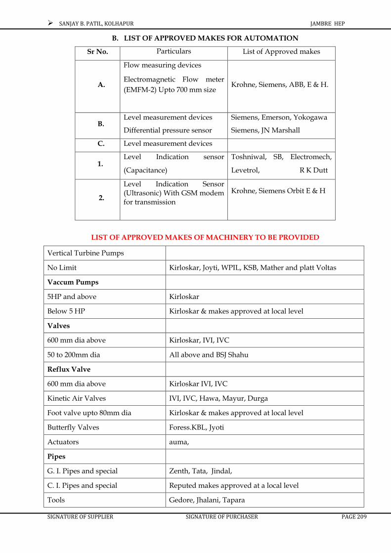
SANJAY B. PATIL, KOLHAPUR JAMBRE HEP
SIGNATURE OF SUPPLIER SIGNATURE OF PURCHASER PAGE 209
B. LIST OF APPROVED MAKES FOR AUTOMATION
Sr No. Particulars List of Approved makes
A.
Flow measuring devices
Electromagnetic Flow meter
(EMFM-2) Upto 700 mm size
Krohne, Siemens, ABB, E & H.
B. Level measurement devices
Differential pressure sensor
Siemens, Emerson, Yokogawa
Siemens, JN Marshall
C. Level measurement devices
1. Level Indication sensor
(Capacitance)
Toshniwal, SB, Electromech,
Levetrol, R K Dutt
2.
Level Indication Sensor (Ultrasonic) With GSM modem for transmission
Krohne, Siemens Orbit E & H
LIST OF APPROVED MAKES OF MACHINERY TO BE PROVIDED
Vertical Turbine Pumps
No Limit Kirloskar, Joyti, WPIL, KSB, Mather and platt Voltas
Vaccum Pumps
5HP and above Kirloskar
Below 5 HP Kirloskar & makes approved at local level
Valves
600 mm dia above Kirloskar, IVI, IVC
50 to 200mm dia All above and BSJ Shahu
Reflux Valve
600 mm dia above Kirloskar IVI, IVC
Kinetic Air Valves IVI, IVC, Hawa, Mayur, Durga
Foot valve upto 80mm dia Kirloskar & makes approved at local level
Butterfly Valves Foress.KBL, Jyoti
Actuators auma,
Pipes
G. I. Pipes and special Zenth, Tata, Jindal,
C. I. Pipes and special Reputed makes approved at a local level
Tools Gedore, Jhalani, Tapara

SANJAY B. PATIL, KOLHAPUR JAMBRE HEP
SIGNATURE OF SUPPLIER SIGNATURE OF PURCHASER PAGE 210
Pressure / Vaccum Gauges Walchand , H-Guru ,marshall
Lifting equipments
Chain pulley block monorail with travelling trolley
Indef, Mooris, , W.H. Brady (5 T Only)
HOT, Cranes W.H. Brady (5 T only) Harculas, Anupam
EOT, Cranes W.H. Brady (5 ton) Anupam, Herculas.
Motor
L.T. Motors
1) Horizontal Motors Kirloskar, Jyoti, Crompton, Alstom,, Siemens,L
2) Vertical Solid shaft motors Kirloskar, Jyoti, Crompton, Alstom, , Siemens,
3) Vertical hollow shaft motors Kirloskar, Jyoti
H.T. Motors Kirloskar, Jyoti, Crompton, Alstom, , Siemens,
Starter L&T , Siemens ,
ELECTRICAL EQUIPEMNT MAKES
Over current and earth fault relay high speed tripping relay.
EE, ABB, , ALSTHOM / AREVA
Static Relay ABB,C &S , ALSTHOM / AREVA
Ammeter / Voltmeter AE, , RISHABH, ENERCON,
Capacitor
L. T. Capacitor 25 k VAR and above Madhav, Prabhodhan Sudarshan
L.T. Capacitor 25 k VAR All above & as approved by MSEB
Cables
i) PVC Submersible ( Copper Conductor) Finolex, Perfect, Calama
Cable
ii)1.1KV armored & Unarmored cable Finolex KEI ,Polycab
iii) 1.1 Kv XLPE cable Finolex KEI ,Polycab
iv) 3.3 kV/6.6kV/11kV/22kV/33kV XLPE Cable
, Gloster , Universal.
v) Control Cable Finoles Gloster Polycab , Deltron,
vi) Cable Termination Rayeechem, Mahindra & Mahindra
H.T. & L.T. Panel ABB, , ALSTHOM / AREVA approved equipments only.
a) D.O.L. L&T., Siemens SEIL, Kirloskar, Teleme - cartique MEI, (BCH)
b) Star Delta L&T., Siemens, SEIL, Bhartiya industries Ltd. Kirloskar Teleme - cartique

SANJAY B. PATIL, KOLHAPUR JAMBRE HEP
SIGNATURE OF SUPPLIER SIGNATURE OF PURCHASER PAGE 211
SWITCHES & FUSE
a) Rotary Thakoor Kaycee L&T Siemens And make as Approved at local level
b) Iron clad Stanley, Ashok, KEW Crompton and make as approved at local level
c) Metal Clad CPI, L&T Elecon Ashok Standard Crompton And make as approved at local level
d) Fuses Switch L&T, Crompton Control & Switch gear, standard electrical, (Upto 30.04.2005)
e) Change over switch on load offload Havells, Control & Switchgear
f) HRC Fuses L&T Alstom Standard, Siemens, Control & Switchgear
OIL CIRCUIT BREAKERS
Moulded Case Circuit Breakers
No Limit L&T, ABB, SEIL, Jyoti, Alstom, Andrew Yule, Havell’s Control & Switchgear, Schneidar.
Upto 630 AMP All above
Air Circuit Brakers
No Limit L&T, Siemens, Control & Switch Gears
Upto 1000 Amp All above & ABB SGIL
Upto 630AMP All above and Easun,
Vaccume Circuite Braker 22 kv/33kv ABB, Crompton, , Siemence, AREVA ,
11Kv All above)
Vaccume Contactors ABB 1.1kv amp to 630 amp - cromton 7.2 & 11 kv-400 amp, Crompton, Alstom,
Earth Leakage Circuit Braker Reputed makes to be decided at local level
Motor Protection relay for LT Motors Reputed Makes to be decided at local level

SANJAY B. PATILSANJAY B. PATILSANJAY B. PATILSANJAY B. PATIL....
JAMBREJAMBREJAMBREJAMBRE HYDRO ELECTRIC PRHYDRO ELECTRIC PRHYDRO ELECTRIC PRHYDRO ELECTRIC PROJECTOJECTOJECTOJECT
1 x 1 x 1 x 1 x 2020202000 KW00 KW00 KW00 KW
SECTION - VI
GUARANTEED TECHNICAL PARTICULARS

SANJAY B. PATIL, KOLHAPUR JAMBRE HEP
1 Full Reservoir Level. 737.00 m Above Mean Sea Level.
2 Minimum Draw Down Level 720.30 m MDDL (I)Above Mean Sea Level.
3 Minimum Draw Down Level 708.00 m (Power) Above Mean Sea Level
4 Minimum Tail Water Level 703.10 m
5 Maximum Tail Water Level 703.5 m (At end of rising Apron)
6 Maximum Gross Head 33.50 M
7 Minimum Gross Head. 17.40 M
8 Design Gross Head 27.00M
9 Diameter of Penstock 2.00 m
10 Thickness Of Penstock. 12.00 mm
11 River bed level 702.935 m Above Mean Sea Level
I TURBINE AND AUXILIARIES:
SR NO. DESCRIPTION UNITS
1 Name of the Manufacturer
2 Type of Turbine
3 Shaft Orientation.
4
Guaranteed rated output of each turbine at rated nethead of 27 m (Gross head-losses in water conductorsystem. Net Design head to be ascertained by Tendererof model tests for discharge.
Head in Meter Min Rated Max
Discharge (Cumecs) & Output (KW) Q P Q P Q P
Percentage Gate Opening
25%
50%
75%
100%
110%
GUARANTEED TECHNICAL PARTICULARS.
The particulars of turbine rated output and efficiency (At Sr.No. 4 & 5) marked with asterisk (*) below shall be guaranteed.
SIGNATURE OF TENDERER SIGNATURE OF PURCHASER 212

SANJAY B. PATIL, KOLHAPUR JAMBRE HEP
SR NO. DESCRIPTION UNITS
5Performance curves, model particulars and
efficiencies
a) Performance curves for output, efficiencies anddischarge verses percentage gate opening underdifferent head conditions shall be submitted along withtender
b) Bonafied turbine efficiencies at rated head for the following outputs
Output
110%
100%
75%
50%
25%
c)Best efficiency of turbine
(It shall be obtainable at the rated Output of not lessthan 2000 kW at design discharge and around 85%gate opening)
%
d) Model Particulars
i) Drawings of model turbine which meets The designdata of this specification shall be Submitted withtender in triplicate.
Yes/No
ii) Latest test reports of above model (to be enclosed)Model tests data duly corrected Along withcalculation of correcting factors Shall be enclosed.
Yes/No
iii) Name & full address of the customers executed Orders on the basis of this model tests . (Along with order number and technical details
Yes/No
iv) Acceptance certificate from above customer Yes/No
6 Discharge:
Turbine discharge at rated head for the followingPercentage of rated output:
110% Cumecs
100% Cumecs
75% Cumecs
25% Cumecs
7 Speed:
a)Specific speed in M.K.S. Units
b)Rated speed in R.P.M. rpm
c)Maximum runaway speed in R.P.M rpm
d)Direction of rotation when viewed from GeneratorEnd.
e)Momentary rise in speed on suddenly reducing loadat 110 % of Rated to rated speed.
f)Time of gate closing for regulation in item-7aboveSeconds
Seconds
SIGNATURE OF TENDERER SIGNATURE OF PURCHASER 213

SANJAY B. PATIL, KOLHAPUR JAMBRE HEP
SR NO. DESCRIPTION UNITS
8
a)Momentary drop in speed in increasing load fromzero To full load
% of rated speed.
b)Time of gate opening for regulation at (a) above Seconds.
9 Flywheel effect of: -
a) The generating unit for regulation stated above kgm²
b) Turbine runner & shaft. kgm²
10 Factor of Safety:-
a)Guaranteed minimum factor of safety under worstConditions based on yield point of the material.
b)Name & location of the part having the factor ofSafely in (a ) above.
11Maximum water hammer pressure (Not to exceed 25%
of Max. head)%
12 Thrust bearing loads:-
a)Load due to turbine rotating parts kg
b)Maximum axial hydraulic thrust down words kg
c)Total down words load on thrust bearing Originatingfrom turbine.
kg
13 Runner:-
a)Material and composition
b)Number of runner blades Nos
c) Runner outlet diameter mm
d)Weight of runner kg
f)Source of runner casting.
e)Method of load regulation.
14 Shaft:-
a)Material and composition.
b)Diameter.
c) Length
d) Weight kg
f)Type of coupling]
e) Material of renewable shaft gland
15 Guide apparatus:-
a) Material of guide vanes
b) Number of guide vanes. Nos.
c)Guide vane PCD mm
d)Height of guide vane mm
e) i.Maximum guaranteed leakage through full closedgated.
LPMs
ii.Torque on runner due to leakage.
f)Description of the method of lubrication
g) Weight of each guide vane
SIGNATURE OF TENDERER SIGNATURE OF PURCHASER 214

SANJAY B. PATIL, KOLHAPUR JAMBRE HEP
SR NO. DESCRIPTION UNITS
16 Casing & speed ring:
Inlet diameter of casing mm
b)Dimensions of casing.
c)Maximum/Design/Working pressure. kg/cm²
d)Test pressure kg/cm²
e)Material of casing.
f) Number of sections of casing Nos
g)Material and construction of speed ring.
h) Number of vanes in speed ring. Nos.
i)Weight of casing. Kg.
j) Dimensions of Man Hole. Mm dia.
17 a)Elevation of Center line of distributor RL above mean sea level
b)Suction head for turbine m
18
a)Critical Value sigma
b)Cavitations guarantee in Kg/1000 hrs.of operation hours
c)Runner throat diameter. mm
d)Guaranteed depth of pitting at any point. mm
19 Draft Tube:
a) Type
b) Elevation of lowest point in draft tube. RL above mean sea level
c) Total length of draft tube. mm
d) Velocity under full load at Draft Tube exists.
20 Guide Vane Servomotor:
a)Number of servomotor Nos.
b) Material of servomotor body and piston.
c) Rating. Kgm.
d)Range of oil pressure of satisfactory operation.
e) Dia of servomotors mm
f) Stroke of servomotors mm
21 Guide Bearing:
a) Type
b) Bearing area. m²
c) Composition of lining material for bearing shell
d) Lubricant.
e) Amount of lubricant in the filling. Lits
f) Maximum temperature of the oil --º C.
g) Method of Lubrication (forced, self, etc.)
h)Type of pumps, offered for pressure lubrication.
i) Type of motor.
j) Rating of motors. H.P.
k)Description of arrangement for preventing loss of oil.
l)Description of arrangement for cooling and changingoil.
m) Amount of cooling water LPMs.
SIGNATURE OF TENDERER SIGNATURE OF PURCHASER 215

SANJAY B. PATIL, KOLHAPUR JAMBRE HEP
SR NO. DESCRIPTION UNITS
22 Turbine Shaft Sealing Gland:
a)Quantity of water required for turbine sealing gland. LPMs
b) Quantity of water required. Liters.
c) Pressure required for sealing water at inlet to sealinggland.
kg/cm²
d) Type of gland offered.
23
Maximum noise level in decibels at different load operations
Db (A)
24 Governing System:
a) Make
b) Type.
c) Rating.
d)Guaranteed sensitivity (Minimum speed range Towhich governor will respond.
e) Range of adjustment in speed setting.
f) Range of adjustment of permanent speed drop.
g) Governing opening & closing times.
h) Description and method of operation.
i) Adjustment range in governor opening and closingtime.
j) Operating Pressure.
k) Provision of gate opening limiter for higher
25 Oil Pump and Sump Tank if any:
a) Number of oil pump per unit. Nos.
b) Type of Pump.
c) Capacity of each pump. H.P.
d) Dimensions of sump tank. ----mm(W)x----mm(L)x---mm(H)
e) Effective volume of sump tank cum.
f) Total volume of oil in the governing system cum.
26 Oil Pressure Vessels if required:
a) Number of vessels per unit Nos
b) Dimension of pressure vessels. ----mm(W)x----mm(L)x---mm(H)
c) Normal volume of oil in vessels. Cum.
d) Normal working pressure. kg/cm²
e) Min. working pressure. kg/cm²
f) Weight of oil pressure vessels. kg.
g) Grade of oil recommended
27 Oil leakage Tanks & Pumps if applicable.
a) No. & type of oil leakage pumps. ----Nos x------
b) Capacity of each pump. H.P.
c) Capacity & speed of pump motor ---H.P. x ----rpm.
d) Dimension of leakage tank ----mm(W) x---mm(L) x----mm(H)
e) Effective volume of tank Ltrs.
SIGNATURE OF TENDERER SIGNATURE OF PURCHASER 216

SANJAY B. PATIL, KOLHAPUR JAMBRE HEP
SR NO. DESCRIPTION UNITS
28 Butterfly Valve :
a) Type.
b) Normal diameter mm
c) Material of valve
d) Material of valve gate.
e) Test pressure. Kg/cm²
f) Factor of safety over yield point.
g) Time of opening. >45sec secs.
h) Time of closing. >30sec. Secs.
i)Leakage through closed valve. Lps.
j) Method of opening.—preferred oil pressure
k) Method of closing------preferred by self weight
i) Weight of valve kg.
m) Weight of heaviest part to be transported.
n) Dimension of largest part to be transported. ---mm (W) x---mm(L) x---mm(H)
o) Length and angle of taper piece. mm
p) Length of inlet pipes For connection to Client'spenstock.
mm
q) Number of servomotor. Nos.
r) Diameter of servomotor. mm
s)Stroke of servomotor. mm
29 Grease Lubrication Equipment if required:-
a) Number of pumps. Nos
b) Capacity & pressure of each pump. –HPx---kg/cm²
c) Type & make of pump.
d) Capacity & No. of grease tank. ---Cum x---Nos.
e) Piping material.
f) Number of grease distributors. Nos.
g) Number of points fed by grease. Nos.
30 Compressed Air System if needed:-
a) Number of compressor. Nos.
b) Type of compressor.
c) Maximum pressure. kg/cm²
d) Rating of motor. HP
e) Number of Air receiver. Nos.
31 Cooling Water System:-
a) Source --- penstock tapping preferred.
b) Capacity of duplex strainer.
c) Material and size of strainer element.
32 Dewatering System:-
a) Number of Pumps. Nos.
b) Type.
c) Discharge of each pump. LPM.
d) Total dynamic head. m
33 Drainage System:-
a) Number of drainage Pump. Nos.
b) Type of drainage pump.
c) Discharge of each pump. LPM
SIGNATURE OF TENDERER SIGNATURE OF PURCHASER 217

SANJAY B. PATIL, KOLHAPUR JAMBRE HEP
SR NO. DESCRIPTION UNITS
34 Heaviest Package of Shipment:-
a) Name
b) Weight. kg
c) Dimensions. ---mm(L) x---mm(W) x------mm(H)
35 Largest Package for Shipment:-
a) Name.
b) Weight. kg
a) Dimensions. ---mm (L) x----mm (W) x---mm (H)
36Heaviest Assembly to the lifted By power house
crane.
a) Name.
b) Weight kg
c) Dimensions. ---mm(L) x---mm(W) X---mm(H)
6.2 GENERATOR AND AUXILIARIES
Note
I
The particular of the each Generator rated output,maximum temperature rise and efficiency marked withasterisk below ) shall be guaranteed. These values willbe applied for evaluation and performance penalization
1 Name of manufacturer.
2 Type of reference.
3Speed and direction of rotation. when viewed from sideopposite to turbine.
–-----rpm x ------
4 a) Normal voltage between phases. 3.3 kV
b) Voltage variation. ±10%
5 a) Frequency. 50 Hz
b) Frequency variatiation +3% and.-5%
6
a) *Guaranteed rated output and total losses Of eachgenerator when operating at rated Voltage of 3300 V.frequency. 50 Hz. p.f. 0.866 Under excited (lagging) andtemperature rise limited to zone A- Operation.
Guaranteed output kw
Guaranteed losses(total) watt .
b) Guaranteed data about each generator output Andlosses at full load of 2309.47KVA @ 0.866 P.F. Underexcited when Continuously operating under Zone-BOutput losses
kw watt.
7Rated Power factor. p.f. 0.866- Over excited-O-0.866Under excited
8Guaranteed maximum temperature.Rise for outputguaranteed in item 7 Above over ambient temperatureof 45° C.
a)Stator winding by RTD/ ETD. -- º C.
b)Rotor winding by resistance. -- º C.
c) Bearing by RTD/ ETD. -- º C
SIGNATURE OF TENDERER SIGNATURE OF PURCHASER 218

SANJAY B. PATIL, KOLHAPUR JAMBRE HEP
SR NO. DESCRIPTION UNITS
9Guaranteed maximum output under Temperature riseas specified in the Specifications under rated conditions.
kw
a) Stator winding by RTD/ ETD. -- º C.
b)Rotor winding by resistance. -- ºC.
c) Bearing by RTD/ ETD. -- º C.
10
Guaranteed weighted average efficiency Frequency and 75° C winding temperature Computed by thesummation of losses Method in accordance with IS 4889-1968 Subject to tolerance in IS: 4722-1968
A) *Bonafied efficiency at
a) 110% full load %
b) 100% full load. %
c) 75% full load. %
d) 50% full load %
e) 25 % full load. %
A) *Guaranteed weighted average efficiency .
11Inherent regulation i.e. increase in voltage at Constantspeed and excitation on taking of
a) 110%full load. %
b) 100% full load. %
c) 75% full load. %
d) 50% full load %
e) 25% full load
12 Generator reactances:-
a) Synchronous reactance ( saturated )
i) Direct axis PU
ii) Quadrature axis. PU
b) Direct axis transient reactances.
i) Saturated. PU
ii) Quadrature axis. PU
c) Sub transient reactance.
i) Saturated. PU
ii) Quadrature PU
13 Negative phase sequence reactance. PU
14 Zero phase sequence reactance. PU
15 Resistance of armature winding per phase.
16 Resistance of field winding.
17 Generator time constant.
i) Direct axis transient open circuit.
ii) Direct axis transient short circuit.
18 Generator characteristics curve.
i) Open circuit saturation curve.
ii) Short circuit saturation curve.
iii)Full load saturation curve at rated power factor.
19 Short circuit ratio.
20 Synchronizing power at KV full load 50 Hz.
p.f. 0.866 . under excited (lagging.)
SIGNATURE OF TENDERER SIGNATURE OF PURCHASER 219

SANJAY B. PATIL, KOLHAPUR JAMBRE HEP
SR NO. DESCRIPTION UNITS
21 Flywheel effect of
a)The rotating parts of the generator kgm²
b) Flywheel GD² kgm²
22Duration for which all part are guaranteed to withstandsafely maximum runaway Ω speed.
Minutes
23
Guaranteed minimum factor of safety Based on yieldpoint of material under Runaway/short circuitconditions and Name & location of part having theminimum Factor of safety.
24 Maximum I x R value. MΩ
25 Inertial constant.
26Maximum runaway speed which all parts Areguaranteed to withstand for 15 minutes.
Rpm
27 Embedded temperature detectors
a) Number. Nos.
b) Type.
28 Excitation Equipment.
a) Name of the manufacturer
b) Type
c) Accuracy of voltage regulation
d) Range of voltage level setting.
e) Range of compounding/reactance Dropcompensation.
f) Range of control in auto mode.
g) Range of control in manual mode.
h) Frequency range of operation. ----------
i) Excitation power feed. K.V.A.
j) Maximum continuous current Rating. Amps.
k) Normal voltage. Volts.
l) Ceiling voltage. Volts.
m)Response ratio.
n) Ambient temperature --º C.
o) Protection class of excitation cubicles.
29Field current for full load on generator At rated powerfactor & terminal voltage.
Amps.
30 Stator.
a) Material of stator core.
b) Insulation of laminations.
c) Number of sections in which stator is divided for transport, if required
d) Insulation of winding.
e) Maximum temperature rise. --º C.
B) Generator Stator Barrel.
a) Height. mm.
b) Inside dimensions. mm
SIGNATURE OF TENDERER SIGNATURE OF PURCHASER 220
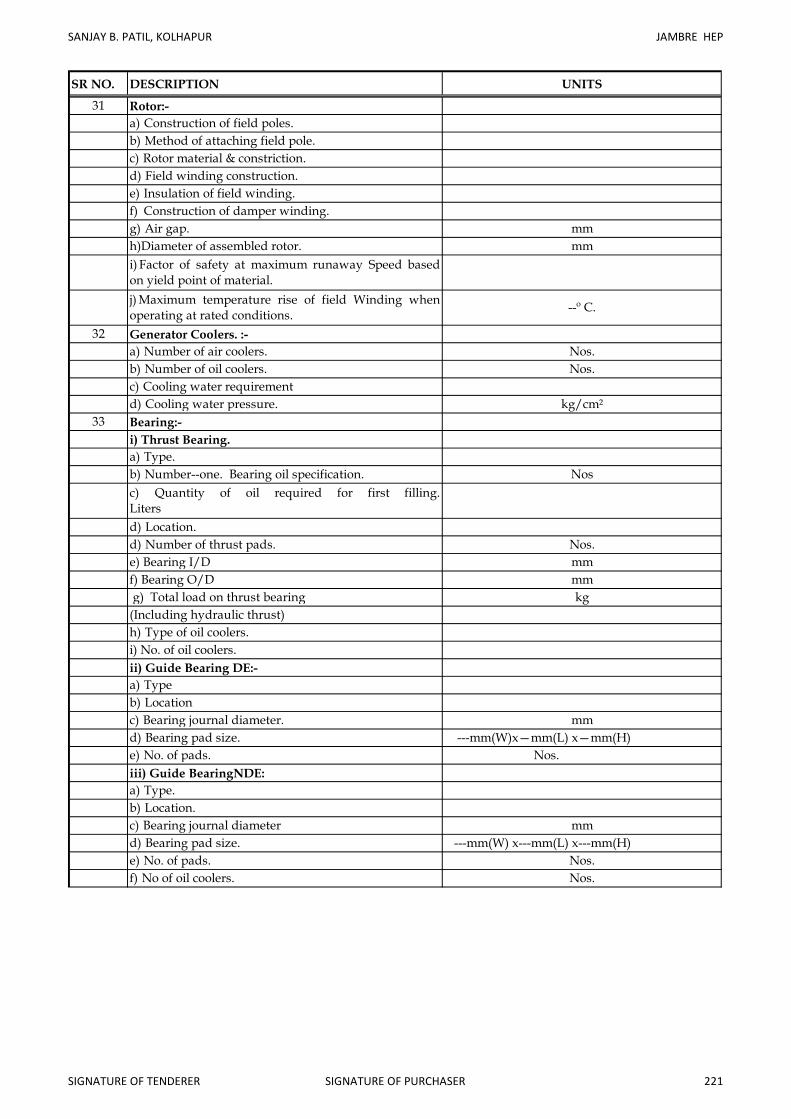
SANJAY B. PATIL, KOLHAPUR JAMBRE HEP
SR NO. DESCRIPTION UNITS
31 Rotor:-
a) Construction of field poles.
b) Method of attaching field pole.
c) Rotor material & constriction.
d) Field winding construction.
e) Insulation of field winding.
f) Construction of damper winding.
g) Air gap. mm
h)Diameter of assembled rotor. mm
i) Factor of safety at maximum runaway Speed basedon yield point of material.
j) Maximum temperature rise of field Winding whenoperating at rated conditions.
--º C.
32 Generator Coolers. :-
a) Number of air coolers. Nos.
b) Number of oil coolers. Nos.
c) Cooling water requirement
d) Cooling water pressure. kg/cm²
33 Bearing:-
i) Thrust Bearing.
a) Type.
b) Number--one. Bearing oil specification. Nos
c) Quantity of oil required for first filling.Liters
d) Location.
d) Number of thrust pads. Nos.
e) Bearing I/D mm
f) Bearing O/D mm
g) Total load on thrust bearing kg
(Including hydraulic thrust)
h) Type of oil coolers.
i) No. of oil coolers.
ii) Guide Bearing DE:-
a) Type
b) Location
c) Bearing journal diameter. mm
d) Bearing pad size. ---mm(W)x—mm(L) x—mm(H)
e) No. of pads. Nos.
iii) Guide BearingNDE:
a) Type.
b) Location.
c) Bearing journal diameter mm
d) Bearing pad size. ---mm(W) x---mm(L) x---mm(H)
e) No. of pads. Nos.
f) No of oil coolers. Nos.
SIGNATURE OF TENDERER SIGNATURE OF PURCHASER 221

SANJAY B. PATIL, KOLHAPUR JAMBRE HEP
SR NO. DESCRIPTION UNITS
iv) Lubrication system oil specification
v)Amount by which rotor must be raised to Dismantle
the thrust bearing.mm
34 Generator Brakes/Jacks:-
a) Type and mode of operation.
b) Speed at which brakes are applied.rpm
c) No. of brakes/ jacks. Nos.
d) Air pressure of brakes. kg/cm²
e) Oil pressure of jacking.
35 Main Shaft:-
a) Material
b) Details of coupling flange.
c) Total weight. kg
36 Weight of generator rotating parts. kg
37 Weight of complete generator kg
39 Current Transformers:-
a) Type
b) Name of manufacturer
c) Rated transformation ratio
d) Output at rated current and accuracy.
e) Accuracy class.
f) Rated over current factor.
i) Times rated current.
ii) Time in seconds. Sec.
g) Knee point voltage.
h) Basis insulation level. kv
i) Winding temperature rise. --º C.
j) Secondary winding resistance. --º C.
40 Neutral grounding equipment.
I) Resistor.
a) Type
b) Name of manufacturer.
c) Material
d) Continuous rating. kA
e) One minute rating. kA
f) Secondary load resistance ( Ohms) Ώ
g) Current rating of resistor.
h) Duty cycle of resistor and cooling medium.
i) Overall dimensions and weight. ---mm(W)x—mm(L)x—mm(H)-----kg
II) Neutral isolating Switch.
a) Type
b) Name of manufacturer
c) Voltage rating. Amps.
d) Frequency. Hz.
e) Normal current Amps.
f) Short time rating
g) 1.2/50 Micro second impulse level
h) 1 minute power frequency dry withstand voltage.
i) Dimensions and weight. ---mm(W)x—mm(L)x—mm(H)-----kg
SIGNATURE OF TENDERER SIGNATURE OF PURCHASER 222

SANJAY B. PATIL, KOLHAPUR JAMBRE HEP
SR NO. DESCRIPTION UNITS
III) Grounding Transformer.
a) Type
b) Name of manufacturer.
c) Standard to which if conforms.
d) Voltage ratio. ----kV/---V.
e) Rating K.V.A.
f) Secondary load resistance. Ώ
g) Frequency. Hz.
IV) Seal of Bushing.
a) Rated voltage. kV
b) One minute dry and wet withstand powerFrequency/voltage
c) Impulse withstands voltage. KV
d) Creepage distance.
e) Bushing height.
41 Generator Terminal Equipment (LAVT)
A) Lightning Arresters:-
a) Type.
b) Name of manufacturer
c) Standard to which if conforms.
d) Number of units. Nos.
e) Rated voltage kV
f) Normal discharge current Amps.
g) Power frequency spark Over voltage kV (rms)
h) impulse spark over Voltage (1.2/50 us wave) KV (peak )
i)Virtual steepness of front of wave For above Micro Seconds.
j) Maximum front of wave impulse Spark over voltage kV (peak)
k) Maximum residual voltage for 10KV dischargecurrent (of µ/20 Micro second wave)
kV (peak)
l) On duration current tests.
a) Current Peak Amps.
b) Virtual duration Micro
m) Overall height mm
n) Total weight. Kg
o) Mounting details.
p) Tests.
B) Protective Capacitors:-
a) Type
b) Name of manufacturer
c) Standard to which if conforms.
d) Voltage rating V.
e) Capacitance. µ Farad
Total weight kg.
f) Mounting details
g) Tests.
SIGNATURE OF TENDERER SIGNATURE OF PURCHASER 223

SANJAY B. PATIL, KOLHAPUR JAMBRE HEP
SR NO. DESCRIPTION UNITS
C) Potential Transformers:-
a) Type.
b) Name of manufacturer
c) Standard to which if conforms
d) Manufacturer’s type. Designation.
e) Rated primary voltage. V
f) Rated secondary voltage V
g) Rated burden VA
h) Accuracy class.
i) Temperature rise at 1.1
Time rated voltage with rated Burden and frequency
j)One minute power frequency withstand test Voltageon primary.(rms)
kV
42 Bus Duct of cubicles:-
a) Type.
b)Name of manufacturer
c) Standard to which if conforms
d) Shape and cross section of bus conductor
e) Rated voltage. kV
f) Impulse test withstand voltage.
i) 1.2/50 Micro second wave kV
ii) one minute power frequency Hz.
iii) Dry withstands test voltage. KV rms
g) Continuous 110% of full load rating Amps
h) Max Temp. rise of bus conductor
At continuous 110 % of full load current rating Amps
i) Bus conductor material
j) Heatlostin segregated phase Bus duct at 110% of fullload
i) Middle phase WATT/meter.
ii) Each other phase --do--
iii) Total heat loss. kW
k) Bus duct enclosure material
l) Phase to phase spacing. mm
i) Standard section length m
m)Minimum creepage distance of insulators. mm
o) Bus bar supporting insulators.
i) Rated voltage. kV
ii) One minute dry & wet withstand power
Frequency voltage... kV
iii) Impulse withstands voltage.
iv) Creep age distance. mm
v) Insulator material
vi) Insulator spacing.
43 Heaviest package:-
For shipment
a) Name
b) Weight kg
c) Dimensions ---mm(L) x----mm(W) x---mm(H)
--º C.
SIGNATURE OF TENDERER SIGNATURE OF PURCHASER 224

SANJAY B. PATIL, KOLHAPUR JAMBRE HEP
SR NO. DESCRIPTION UNITS
44 Largest package :-
For shipment.
a) Name
b) Weight kg
c) Dimensions --mm(L) x ---mm(W) x ---mm(H)
45 Heaviest assembly to be lifted. :-
by power house crane.
a) Name
b) Weight kg
d) Dimensions ---mm(L) x ---mm(W) x ---mm(H)
6.3 UNIT CONTROL PANELS:-
Relays:
1 Maker¢s Name
2 Type
3 Rated Voltage
4 Maximum permissible current loading
i) Continuous
ii) L Second thermal
iii) Dynamic
5 Fixed tripping time lag
6 Range of adjustment of tripping Time
7 a) Retarded tripping
b) Instantaneous tripping
8 Relay pick up and basis setting range available
9 Fall back ratio
10 Power consumption of measuring circuits
a) Normal Service
b) Tripping condition
11 Temperature range
12 Test Voltage
13Power consumption at rated auxiliary D.C. SupplyVoltage
i) During normal service
ii) During Tripping
14 Current Coil Rating
15 Maximum V.A. Burden
i) Operating Coil
ii) Restraining Coil
16 Power Consumption
i) Operating Coil
ii) Restraining Coil
17 Is the slope setting variable Yes/No
18 Harmonic restraint provided or not With details.
19 Is 5th Harmome by pass provided
20 Range of HT/ ratios over which the relay can be used .
21 Details of Auxiliary
SIGNATURE OF TENDERER SIGNATURE OF PURCHASER 225

SANJAY B. PATIL, KOLHAPUR JAMBRE HEP
SR NO. DESCRIPTION UNITS
22 Operating Time
a) AT 2 x In
b) AT 10 x In
Auxiliary Ac and Dc power supply requirement
i) Rated Voltage
ii) Tolerance on rated voltage above and frequency
iii)a) Rated current or rated output voltage
b) Peal load
iv)Details of protection and monitoring providing forthe equipement
6.3.2 Instruments and Meters:
1 Maker’s name and type of instrument
2 Size.
3 Whether magnetically shielded or not Yes/No
4 Limits of error in the effective range
5 Maximum scale length
6 Total deflection angle
7 Whether treated for tropical
8 Auxiliary supply
9 Short time overload
10 V.A. Burden VA.
i) Current Coil
ii) Potential Coil
11 Power Consumption Watt
i) Current Coil
ii) Potential Coil
12 Continuous overload rating of current Coil Amps
13 Continuous over voltage rating of potential Coil Amps
14 Short time over voltage rating of the same.
15 Limits of error at U.P.F.
i) 125%, 25% or rated current
ii) 10% of rated current
16 Limits of error at 0.5 P.F. under excited (lag)
i) 125%, 25% or rated current
ii) 10% of rated current
17Suitability for measurement of unbalanced 3 phases, 3wire system
18 Number of digit on the meter
19 Speed of rotor rev/kwh.
20 Reverse running stop provided Yes/No
21 Reference conditions of influencing quantities
22 Temperature of calibration ---º C.
23 Accuracy
i) 125%, 25% or rated current
ii) 10% of rated current
iii) Active energy measurement KWH
iv) Reactive energy measurement KVAR
24 Weight
25 Other details, if any
26 Description Leaflet tolerance Nos. submitted.
SIGNATURE OF TENDERER SIGNATURE OF PURCHASER 226

SANJAY B. PATIL, KOLHAPUR JAMBRE HEP
SR NO. DESCRIPTION UNITS
6.3.3 Terminal Block:
1 Make and country of manufacture
2 Construction details
3 Voltage grade kV
4 Current rating Amps.
5Numbers of 2.5 mm copper cables that can beconnected
Nos.
6Whether shrouding provided for terminals at voltagemore than 220 V. AC DC.
Yes/No
7 Number of spare Terminal Nos.
8 Marking
6.3.4 Panel Wiring:
1 Insulation of wiring
2 Size of wiring conductor
a) P. T. Circuits Sq. mm
b) C. T. Circuits Sq. mm
c) D. C. Supply Circuits Sq. mm
d) Other Circuits Sq. mm
3 Sizes of earthing bar for safety earthing --mm x --mm
4 Type of terminals provided on wiring
5 Wiring conductor aluminum / copper
6.3.5 Unit Control Panels:
1 Maker’s Name
2 Type of Construction
3 Thickness of sheet steel
a) Front mm
b) Back mm
c) Side mm
4 Weight of each panel section kg
5 Tentative overall dimensions of panel ---mm(L) x----mm(W) x ---mm(H)
6 Total weight of panel kg
7 Space required of installation panel --mm(L) x---mm(W) x----mm(H)
8 Details of tropical treatment
9 Details of painting
10 Largest package for transport
a) Gross weight kg
b) Overall dimensions --mm(L) x---mm(W) x---mm(H)
6.4 Earthing:
1 Conductor of material
2 Size --mm x ---mm
3 Type of end connection
SIGNATURE OF TENDERER SIGNATURE OF PURCHASER 227

SANJAY B. PATIL,KOLHAPUR JAMBRE HEP
Sr. No. Description Unit
1Name of manufacturer
2 Service
3 National standard applicable
4 Vector group
5 Guaranteed no load voltage ratio
6 Normal turns ratio
7 Type of cooling.
8 Guaranteed continuous maximum Rating for specified
cooling temperature Rise as per IS 2026 and ambient.
9 Guaranteed equipment continuous maximum rating as per IS
2026 Standard temperature rise and ambient temperature.
10 Continuous overload capacity for 2 Hrs. after continuous
rated full load run.
11 Short time thermal rating of L.V. winding in KVA and
duration.
12 Thermal time constant in hours.
13 Guaranteed temperature rise limits when tested according
to IS 2026
i) Winding measured by resistance
ii) Oil measured by the thermometer in top oil
iii) Core
14 Guaranteed maximum temperature rise, after full load run
followed by two hours. Overload of 20 percent Of all by
thermometer above ambient temp. 450C
15 Guarantee withstands time without injury with three phase
short circuit at the terminals.
16 Guaranteed no load loss without tolerances permissible as
per IS 2026.
i) At rated voltage and frequency
ii) At 90% rated voltage and frequency
iii) At 110 percent rated voltage and frequency
17 Guaranteed full load copper loss at rated current at 750
temperature, in kW without tolerances permissible as per IS
2026
18 Total guaranteed losses at maximum continuous rating at
rated voltage and frequency.
19 Efficiency at 750 C at unit power factor
at 100% rating
at 75% rating
at 50% rating
at 25% rating
20 Guaranteed efficiency at 750 C at 0.866 power factor lagging
at 100% rating
at 75% rating
POWER TRANSFORMER
SIGNATURE OF TENDERER SIGNATURE OF PURCHASER 228

SANJAY B. PATIL,KOLHAPUR JAMBRE HEP
Sr. No. Description Unit
at 50% rating
at 25% rating
21 Maximum efficiency and the load at which maximum
efficiency accure
22 Guaranteed magnetizing current at rated frequency at
At rated voltage
At 90% rated voltage
At 110 percent rated voltage
23 1. Reactance at rated current and frequency
2. Reactance drop on full load
3. Resistance at rate current and frequency
4. Resistance drop on full load
5. Guaranteed impedance at rated current and frequency
at 750 C on each tap
6. Guaranteed impedance drop on full load
7.Guaranteed regulation on full load at 750
C, 0.866 power
factor. Expressed as a percentage of normal secondary drop
8. Guaranteed regulation on full load 750
C, 0.866 power
factor. Expressed as percentage of normal secondary voltage.
9. Zero phase sequence impedance
24 Nature of tap changing gear provided total range, number of
steps variation on each steps of transformation ratio
provided on H.V. winding and position of tap on H.V.
winding.
25 Maximum flux density at normal voltage and 110
percent normal, voltage and frequency
a) Core
b) Yoke
26 Volt. Ampere turns corresponding to maximum working flux
density and 110 percent maximum working flux density.
27 Exciting kW per kg. Of iron at
1. Rated induction
2. Induction corresponding to 110 percent normal voltage.
28Maximum current density in winding in amp. Sq.cm.
i) H.V. winding
ii)L.V. winding
28A. Nature of insulation of
1. Laminations of core
2. L.V. winding
SIGNATURE OF TENDERER SIGNATURE OF PURCHASER 229
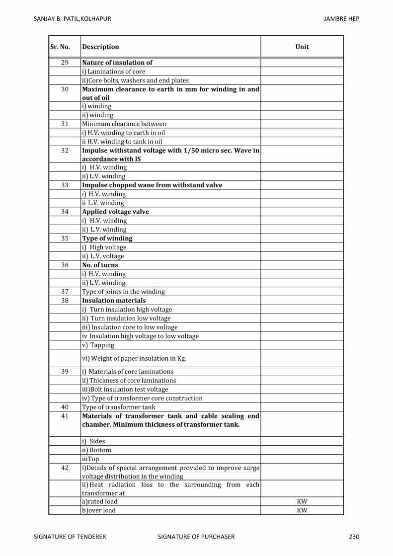
SANJAY B. PATIL,KOLHAPUR JAMBRE HEP
Sr. No. Description Unit
29 Nature of insulation of
i) Laminations of core
ii)Core bolts, washers and end plates
30 Maximum clearance to earth in mm for winding in and
out of oil
i) winding
ii) winding
31 Minimum clearance between
i) H.V. winding to earth in oil
ii H.V. winding to tank in oil
32 Impulse withstand voltage with 1/50 micro sec. Wave in
accordance with IS
i) H.V. winding
ii) L.V. winding
33 Impulse chopped wane from withstand valve
i) H.V. winding
ii L.V. winding
34 Applied voltage valve
i) H.V. winding
ii) L.V. winding
35 Type of winding
i) High voltage
ii) L.V. voltage
36 No. of turns
i) H.V. winding
ii) L.V. winding
37 Type of joints in the winding
38 Insulation materials
i) Turn insulation high voltage
ii) Turn insulation low voltage
iii) Insulation core to low voltage
iv Insulation high voltage to low voltage
v) Tapping
vi) Weight of paper insulation in Kg.
39 i) Materials of core laminations
ii) Thickness of core laminations
iii)Bolt insulation test voltage
iv) Type of transformer core construction
40 Type of transformer tank
41 Materials of transformer tank and cable sealing end
chamber. Minimum thickness of transformer tank.
i) Sides
ii) Bottom
iiiTop
42 i)Details of special arrangement provided to improve surge
voltage distribution in the winding
ii) Heat radiation loss to the surrounding from each
transformer at
a)rated load KW
b)over load KW
SIGNATURE OF TENDERER SIGNATURE OF PURCHASER 230

SANJAY B. PATIL,KOLHAPUR JAMBRE HEP
Sr. No. Description Unit
43 Details of painting
i) at works
ii) at site
44 Noise level at rated output DbA
45 Cooling media
i) Grade of oil
ii) Quantity of oil on transformer Lit.
iii) Whether 10 percent extra oil is supplied
iv) Test pressure for oil, pipes valves etc.
46 Bushings
a. Type
b. Make
c. Standard specification
d. Country of origin
e. Test procedure
1. Guaranteed impulses withstand voltage for 1/50 micro
second impulse wave.
HV L.V HV
2. Guaranteed one minute dry withstand power frequency Neutral
3.Guaranteed one minute wet withstand power frequency
voltage
Hz Hz Hz
4.Momentary power frequency dry withstand voltage KV KV KV
5. Visible power frequency discharge voltage KV KV KV
6. Under oil flashover or puncture withstand power
frequency voltage
KV KV KV
7. Under oil flash over or puncture withstand impulse
voltage
KV KV KV
8. Creep-age distance KV KV KV
9. Maximum current ratings MM MM MM
10. Power factor of bushing Amp. Amp. Amp.
11. Terminal arrangement
12. Grade of oil
13. Quantity of oil Lt. Lt. Lt.
14. Material of condenser
15. Weight of assembled bushing Kg. Kg. Kg.
47 Minimum phase to phase and phase to earth clearness in
air live parts at the top of bushing
1. H.V. neutral of earth Mm
2. L.V. to earth
48 Dimensions and other particulars
1) Net weight in Kg. Of
1. Core and frame
2. H.V. winding
3. L.V. winding
4. Copper in H.V. winding Kg.
5. Copper in L.V. winding Kg.
6. Tank Kg.
7. Complete transformer with oil, fitting and accessories Kg.
8. Conservator with oil Kg.
9. Marshalling box Kg.
10. Oil Kg.
SIGNATURE OF TENDERER SIGNATURE OF PURCHASER 231

SANJAY B. PATIL,KOLHAPUR JAMBRE HEP
Sr. No. Description Unit
2) Approximate weight in kg. Of
1. Insulated copper conductor Kg.
2. Electrical steel laminations Kg.
3. Constructional steel Kg.
3) Dimensions in mm of length, breadth, height, weight
1.Tank with core and winding arranged for transport
2. Largest package for transport
3. Heaviest package for transport
4. Assembled transformer
49 Additional information
1. Whether oil temperature indicator provided
2. Type and size of temperature indicator and whether
supervisory alarm and trip contacts provided.
3. Type of oil level indicator and whether supervisory alarm
and trip contact provided.
4. Type of gas operated relay and whether supervisory alarm
and trip contact provided
5. Whether local and remote winding temp. Indicator with
supervisory alarm and trip contact provided and its
type/make.
6. Type and size of thermostat used.
7.No. of breather provided their make and sizes.
8. Type of dehydrating agent used for breather
9.Capacity of conservator raised in liters and as percent age
of the main tank.
10.Valve sizes and numbers
a) Drain valve cms.
b) Filter valves cms.
c) Sampling valve cms.
SIGNATURE OF TENDERER SIGNATURE OF PURCHASER 232
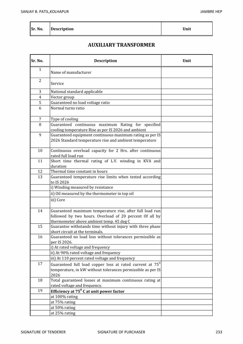
SANJAY B. PATIL,KOLHAPUR JAMBRE HEP
Sr. No. Description Unit
Sr. No. Description Unit
1Name of manufacturer
2Service
3 National standard applicable
4 Vector group
5 Guaranteed no load voltage ratio
6 Normal turns ratio
7 Type of cooling
8 Guaranteed continuous maximum Rating for specified
cooling temperature Rise as per IS 2026 and ambient
9 Guaranteed equipment continuous maximum rating as per IS
2026 Standard temperature rise and ambient temperature
10 Continuous overload capacity for 2 Hrs. after continuous
rated full load run
11 Short time thermal rating of L.V. winding in KVA and
duration
12 Thermal time constant in hours
13 Guaranteed temperature rise limits when tested according
to IS 2026
i) Winding measured by resistance
ii) Oil measured by the thermometer in top oil
iii) Core
14 Guaranteed maximum temperature rise, after full load run
followed by two hours. Overload of 20 percent Of all by
thermometer above ambient temp. 45 deg C
15 Guarantee withstands time without injury with three phase
short circuit at the terminals.
16 Guaranteed no load loss without tolerances permissible as
per IS 2026.
i) At rated voltage and frequency
ii) At 90% rated voltage and frequency
iii) At 110 percent rated voltage and frequency
17 Guaranteed full load copper loss at rated current at 750
temperature, in kW without tolerances permissible as per IS
2026
18 Total guaranteed losses at maximum continuous rating at
rated voltage and frequency.
19 Efficiency at 750 C at unit power factor
at 100% rating
at 75% rating
at 50% rating
at 25% rating
AUXILIARY TRANSFORMER
SIGNATURE OF TENDERER SIGNATURE OF PURCHASER 233

SANJAY B. PATIL,KOLHAPUR JAMBRE HEP
Sr. No. Description Unit
20 Guaranteed efficiency at 750
C at 0.866 power factor
lagging
at 100% rating
at 75% rating
at 50% rating
at 25% rating
21 Maximum efficiency and the load at which maximum
efficiency accure
22 Guaranteed magnetizing current at rated frequency at
At rated voltage
At 90% rated voltage
At 110 percent rated voltage
23 1. Reactance at rated current and frequency
2. Reactance drop on full load
3. Resistance at rate current and frequency
4. Resistance drop on full load
5. Guaranteed impedance at rated current and frequency at
750 C on each tap
6. Guaranteed impedance drop on full load
7. Guaranteed regulation on full load at 750
C, 0.866 power
factor. Expressed as a percentage of normal secondary drop
8. Guaranteed regulation on full load 750
C, 0.866 power
factor. Expressed as percentage of normal secondary voltage.
9. Zero phase sequence impedance
24 Nature of tap changing gear provided total range,
number of steps variation on each steps of
transformation ratio provided on H.V. winding and
position of tap on H.V. winding.
25 Maximum flux density at normal voltage and 110
percent normal, voltage and frequency
a. Core
b.Yoke
26 Volt. Ampere turns corresponding to maximum working
flux density and 110 percent maximum working flux
density.
27 Exciting kW per kg. Of iron at
1 Rated induction
2. Induction corresponding to 110 percent normal voltage.
28Maximum current density in winding in amp. Sq.cm.
1. H.V. winding
2. L.V. winding
28A. Nature of insulation of
1. Laminations of core
2. L.V. winding
29 Nature of insulation of
1. Laminations of core
2. Core bolts, washers and end plates
SIGNATURE OF TENDERER SIGNATURE OF PURCHASER 234

SANJAY B. PATIL,KOLHAPUR JAMBRE HEP
Sr. No. Description Unit
30 Maximum clearance to earth in mm for winding in and
out of oil
i)winding
ii) winding
31 Minimum clearance between
i) H.V. winding to earth in oil
ii) H.V. winding to tank in oil
32 Impulse withstand voltage with 1/50 micro sec. Wave in
accordance with IS
i) H.V. winding
ii) L.V. winding
33 Impulse chopped wane from withstand valve
i) H.V. winding
ii) L.V. winding
34 Applied voltage valve
i) H.V. winding
ii) L.V. winding
35 Type of winding
i) High voltage
ii) L.V. voltage
36 No. of turns
i) H.V. winding
ii) L.V. winding
37 Type of joints in the winding
38 Insulation materials
i) Turn insulation high voltage
ii) Turn insulation low voltage
iii Insulation core to low voltage
iv Insulation high voltage to low voltage
v) Tapping
vi) Weight of paper insulation in Kg.
39 i) Materials of core laminations
ii) Thickness of core laminations
ii Bolt insulation test voltage
iv) Type of transformer core construction
40 Type of transformer tank
41 Materials of transformer tank and cable sealing end
chamber. Minimum thickness of transformer tank.
i) Sides
ii) Bottom
iii) Top
42 i) Details of special arrangement provided to improve surge
voltage distribution in the winding
ii) Heat radiation loss to the surrounding from each
transformer at
a) rated load KW
b) over load KW
43 Details of painting
i) at works
ii ) at site
44 Noise level at rated output DbA
SIGNATURE OF TENDERER SIGNATURE OF PURCHASER 235

SANJAY B. PATIL,KOLHAPUR JAMBRE HEP
Sr. No. Description Unit
45 Cooling media
i) Grade of oil
ii)Quantity of oil on transformer Lit.
ii )Whether 10 percent extra oil is supplied
iv) Test pressure for oil, pipes valves etc.
46 Bushings
a. Type
b. Make
c. Standard specification
d. Country of origin
e. Test procedure
1. Guaranteed impulses withstand voltage for 1/50 micro
second impulse wave. HV L.V HV
2. Guaranteed one minute dry withstand power frequency Neutral
3. Guaranteed one minute wet withstand power frequency
voltage Hz Hz Hz
4.Momentary power frequency dry withstand voltage KV KV KV
5. Visible power frequency discharge voltage KV KV KV
6 Under oil flashover or puncture withstand power
frequency voltageKV KV KV
7. Under oil flash over or puncture withstand impulse
voltageKV KV KV
8. Creep-age distance KV KV KV
9. Maximum current ratings MM MM MM
10.Power factor of bushing Amp. Amp. Amp.
11. Terminal arrangement
12. Grade of oil
13. Quantity of oil Lt. Lt. Lt.
14 Material of condenser
15. Weight of assembled bushing Kg. Kg. Kg.
47 Minimum phase to phase and phase to earth clearness in
air live parts at the top of bushing
1. H.V. neutral of earth Mm
2 L.V. to earth
48 Dimensions and other particulars
1) Net weight in Kg. Of
1.Core and frame
2.H.V. winding
3.L.V. winding
4.Copper in H.V. winding Kg.
5.Copper in L.V. winding Kg.
6. Tank Kg.
7. Complete transformer with oil, fitting and accessories Kg.
8. Conservator with oil Kg.
9. Marshalling boxKg.
10. Oil Kg.
SIGNATURE OF TENDERER SIGNATURE OF PURCHASER 236

SANJAY B. PATIL,KOLHAPUR JAMBRE HEP
Sr. No. Description Unit
2) Approximate weight in kg. Of
1. Insulated copper conductor Kg.
2. Electrical steel laminations Kg.
3. Constructional steel Kg.
3) Dimensions in mm of length, breadth, height, weight
1. Tank with core and winding arranged for transport
2. Largest package for transport
3. Heaviest package for transport
4. Assembled transformer
49 Additional information
1. Whether oil temperature indicator provided
2. Type and size of temperature indicator and whether
supervisory alarm and trip contacts provided.
3. Type of oil level indicator and whether supervisory
alarm and trip contact provided.
4. Type of gas operated relay and whether supervisory
alarm and trip contact provided
5. Whether local and remote winding temp. Indicator with
supervisory alarm and trip contact provided and its
type/make.
6. Type and size of thermostat used.
7. No. of breather provided their make and sizes.
8. Type of dehydrating agent used for breather
9. Capacity of conservator raised in liters and as percent age
of the main tank.
10 Valve sizes and numbers
a) Drain valve cms
b) Filter valves cms
c) Sampling valve cms
SIGNATURE OF TENDERER SIGNATURE OF PURCHASER 237

SANJAY B. PATIL, KOLHAPUR JAMBRE HEP
1 General Information
a) Name of Company As per our attached supplier list.
b) Model No. and name of
manufacturerAs per our manufacturer standard.
2 Type and class of Crane EOT Type M2 Class
a) Crane Structure I Section
b)Main hoist and Aux. Hoist
to be design by manufacturer of
main plant.c) Cross traverse 8 m/m
d) Long travel 15 m/m
3 Safe working load (Main / Aux.
Hoist)as per requirment.
4Center to center of track rails (Span) as per requirment of TG plant.
5 Operating Speed (loaded)
a) Hoisting (Main & Aux.) 2 m/m
b) Cross travel To be furnished by bidder.
c) Long travel To be furnished by bidder.
d)Micro Speed for all motions To be furnished by bidder.
6 Minimum working clearance
requiredi. Distance from center of runway rail
to nearest side Obstruction1200mm
ii.Vertical distance from top of runway
rail to nearest side Obstruction2600mm
iii. Distance from floor to top of runway
rail
9 m (Approx from Service Bay
Floor)iv. Nearest position of hook to center
line of runaway rail1.3 m (Approx)
v. Vertical clearance to underside of
bridge girder800mm
7Type of hook supplied / Make
C type-auxialy hook.Ramshorn for
main hook.8 Height of hook above floor level 6 m (Approx)
9 Drop of hook below floor level 7.5 m (Approx)
10Section of runway rail recommended 60 Ponds rail
11 Type of main girder to be decided by manufacturer.
i. Braced, plain or rolled steel hoist
ii. Riveted or fusion welded
12 End Carriages
a) Wheel base 4 m
b) Material of wheels EN 9 Forged
c) Maximum load excluding impact on
traveling wheelsto be decided by manufacturer.
JAMBRE HEP 1 X 2000kW
SCHEDULE OF GUARANTEED TECHNICAL PARTICULARS OF CRANE
Sr No.. Particulars
to be decided by manufacturer.
SIGNATURE OF TENDERER SIGNATURE OF PURCHASER 238

SANJAY B. PATIL, KOLHAPUR JAMBRE HEP
13 Crab. Center to Center of Traverse
wheels2 m (Approx)
14 Hoisting rope
a) Diameter 18 mm (Approx)
b) Construction Fabricated steel
c) Quality of steel To meet IS Standards
d) No. of falls 8 Fall on Main 4 Fall on Aux.
e) Minimum breaking load to be decided by manufacturer.
f) Factor of safety 1.5 to 2
15 Description of brakes for
a) Traversing brakes
b) Traveling brakes
16 Particulars of safety devices / limit
switchesTwo way rotary type.
17 Electrical Equipment
a) Details of controls and protections for
power supply to hoist motor and
lighting from crane
to be decided by manufacturer.
b) Motor for hoist / Trolley travel
bridge traveli. Make As per our supplier standard.
ii. Type Squirrel Cage Type
15.27 HP Hoist
7.64 HP A. Hoist
3 HP C.T & L.T
iv. Insulation class
v. Enclosure type
vi. Brushes – type, number
vii. Maximum torque (pull out torque)
viii. Full load speed to be decided by manufacturer.
ix. Maximum temperature rise of stator
windinga) By resistance Method
b) By Thermometer Method
c) Details of motor controllers like
make, steps or points in each
direction of motion and control &
protective equipment
to be decided by manufacturer.
d)National Standards to which the
above would conform
IS 807, 3177 More clarity can be
given during detailed engineering.
e) i.Make of electro-magnetic brake
Will be as per our supplier
standard.ii. Make of electro-hydraulic thruster
brake
SOC / AMAG / SA or any other as
per our supplier standard.f) Details of runway conductors and
collectorsto be decided by manufacturer.
18 Net weight
i. Complete unladen crane to be decided by manufacturer.
ii. Complete unladen crab to be decided by manufacturer.
19 Tools and accessories supplied to be decided by manufacturer.
20 General arrangement drawing
enclosed Yes
100- 18 AC EHT Type
iii. Capacity / rating
SIGNATURE OF TENDERER SIGNATURE OF PURCHASER 239

1 Name of
manufacturerAs per enclosed vender list
2 Type of gears Helical, Hardened & Ground3 Shaft Orientation Vertical4 Shaft off set Horizontal off set5 Number of stages Single Stage6 Input speed To be furnished by bidder.7 Output speed 750 RPM8 Gear Ratio To be furnished by bidder.9 Service factor 2
Overall Efficiency of
gear box100%80%60%40%
11 Runaway speed To be furnished by bidder.
JAMBRE HEP 1 X 2000kW
GUARANTEED TECHNICAL PARTICULARS OF GEAR BOX
Sr No.. Particulars
10
239 a

SANJAY B. PATILSANJAY B. PATILSANJAY B. PATILSANJAY B. PATIL....
JAMBREJAMBREJAMBREJAMBRE HYDRO ELECTRIC PROJECTHYDRO ELECTRIC PROJECTHYDRO ELECTRIC PROJECTHYDRO ELECTRIC PROJECT
1 x 1 x 1 x 1 x 2020202000 KW00 KW00 KW00 KW
SECTION - VII
WORKING TABLE & TENDER DRAWINGS

JAMBRE HYDRO ELECTRIC PROJECT
(1 x 2000 kW)
WORKING TABLE FOR POWER GENERATION AT (75% YIELD)
Year - 1989 - 1990
Annexure- V
Rl. in m. Capacity in Mcum
FRL 737.000 Content 23.230 Say 23.23
MDDL (Irri) 708.000 Content 0.028 Say 0.03
MDDL (P) 721.000 Content 6.80
River Bed 702.935 -
TWL 703.500 -
RELEASESWater from
Spill
CONTINUOUS
POWER
R.L. in Capacity
in
Irrigation +
W.S.
Additional
water for
power
R.L. Capacity 8 x Q x H
Metres In Mcum In Mcum In Mcum In Mcum In Mcum In Mcum In Cumecs Cumecs In Mcum In Mcum M. In Mcum M. M. M. kW MKWH kW
1 2 3 4 5 6 7 8 9 10 11 12 13 14 15 16 17 18 19 20 21 22 23 24 25
1 Jun 30 5 30 718.12 3.82 19.80 23.62 0.56 3.86 4.42 8.185 11.21 0.01 4.43 733.49 19.19 725.805 703.500 22.31 1460.56 0.22 2000.00 73.03
2 Jul 31 24 31 733.49 19.19 27.02 46.21 0.56 22.38 22.94 8.565 7.88 0.04 22.98 737.00 23.23 735.245 703.500 31.75 2175.12 1.62 2000.00 108.76
3 Aug 31 19 31 737.00 23.23 15.67 38.90 0.56 15.04 15.60 7.357 7.46 0.07 15.67 737.00 23.23 737.000 703.500 33.50 1971.70 1.16 2000.00 98.59
4 Sep 30 6 30 737.00 23.23 4.82 28.05 2.76 1.99 4.75 7.330 7.46 0.07 4.82 737.00 23.23 737.000 703.500 33.50 1964.51 0.35 2000.00 98.23
5 Oct 31 3 31 737.00 23.23 1.20 24.43 2.76 0.00 2.76 8.244 7.69 0.24 3.00 735.03 21.43 736.015 703.500 32.52 2144.36 0.20 2000.00 107.22
6 Nov 28 3 30 735.03 21.43 0.00 21.43 2.20 0.00 2.20 7.275 8.16 0.23 2.43 733.28 19.00 734.155 703.500 30.66 1784.15 0.15 2000.00 89.21
7 Dec 27 4 31 733.28 19.00 0.00 19.00 3.31 0.00 3.31 8.513 8.80 0.22 3.53 730.55 15.47 731.915 703.500 28.42 1935.26 0.21 2000.00 96.76
8 Jan 30 3 31 730.55 15.47 0.00 15.47 3.05 0.00 3.05 9.414 9.74 0.20 3.25 727.80 12.22 729.175 703.500 25.68 1933.55 0.17 2000.00 96.68
9 Feb 28 3 28 727.80 12.22 0.00 12.22 2.36 0.00 2.36 7.804 10.82 0.19 2.55 725.39 9.67 726.595 703.500 23.10 1441.91 0.12 2000.00 72.10
10 Mar 28 3 31 725.39 9.67 0.00 9.67 2.63 0.00 2.63 8.697 13.33 0.38 3.01 719.13 6.66 722.260 703.500 18.76 1305.26 0.11 2000.00 65.26
11 Apr 0 0 30 719.13 6.66 0.00 6.66 2.42 0.00 2.42 0.000 16.44 0.31 2.73 718.29 3.93 718.710 703.500 15.21 0.00 0.00 2000.00 0.00
12 May 0 0 31 718.29 3.93 1.68 5.61 1.58 0.00 1.58 0.000 17.00 0.21 1.79 718.12 3.82 718.205 703.500 14.70 0.00 0.00 2000.00 0.00
70.19 24.75 43.27 68.02 2.17 70.19 4.32
Maximum Head is 33.5 m & Minimum is 14.94 m.From observation of the working table head variation for entire year for 75% dependable yield is 33.50 m to 14.70
Power Generation which can be catered for is about 2000 kW. is about 2000 kW. This machine can operate upto about 30% of power at lower range. Generation shown is at peak discharge for few hours during rotation days.
This is a range slightly wider for Francis turbine. Francis Turbine with a design head of 26.8 m can operate between 33.50 m Maximum Head to 17.4 m Minimum Head.
Heads lesser than 17.4 occurs only for last two months and Power Generation during the period is very low.Hence Francis Turbine is opted as against costly Kaplan Turbine.
Annual energy generation is bout 4.32 Mus. Machine is overloaded in July upto 2174 kW & hence load factor is above 109%. Machine will be designed for continuous overload to the extent to cater this extra power generation.
At the end of the monsoon reservoir reaches FRL & there after the full irrigation is utilised which leves closing level of RL 718.12m. The same level is treated as opening level while preparing the working table.
This working table is prepared on the basis of information provided by the Executive Engineer, Medium Project Division II Kolhapur.
HEAD
AVAILA
BLE
UNITS
Total
Release
Water
for
Power
Discharge
for power
Power
DischargeTWL
MEAN
LAKE
LEVELS
Load
Factor in %
Installed
Capacity in
kW
Sr.No. MonthPower
Days
Hours of
operationNo of Days
OPENING CLOSING
INFLOWTOTAL
CONTENTS
LAKE
LOSSES
TOTAL
WITHDRAW
AL


CONTROL ROOM
RL 710.000M
OFFICE
D.G. ROOM
(5.8X4.5)
RL 710.000M
TOILET
RL 710.000M
STORE
RL 710.000M
5.8
75
5.000
3.000
25
.0
00
9.000
SWITCH YARD
RL 710.000M
SERVICE BAY
RL 710.000M
ROLLING SHUTTER
ROLLING SHUTTER
4.325 6.700 6.700
6.5
00
6.5
00
5.0006.700
6.000
6.7006.1506.050
25.600
6.1
50
6.1
50
12
.3
00
13
.4
00
0.5
50
0.5
50
10
6.7
00
6.7
00
TAIL CANAL
RL 700.450M
1:6 UPTO 18000
UNLINED THEREAFTER
POWER HOUSE PLANNAME OF DRG :-
JAMBRE HEP (1 X 2.0 MW) TAL - CHANDGAD DIST - KOLHAPUR
email : - [email protected],
FINALREVISIONORIGINAL
DATE :- 2009 - 16 - 07DRG NO - DKA/JAMBREHEP/2009-10/1-1 Er. S.L.DIWANCHECKED BY
Er.SAGAR YALUGADE Er.AMOL P. JADHAV
AUTOCAD BY:-
252,'E' 9, Deepti Park, Assembly Road, Tarabai Park, Kolhapur
221B/1A, CENTER ONE, E WARD, TARABAI PARK, KOLHAPUR-416 003DIWAN KHADILKAR CONSULTANTS PVT. LTD.
SANJAY PATIL, Class I Regd. Govt. Contractors,

12345678
B
C
D
E
F
G
HH
G
F
E
D
C
B
A
8 7 6 5 4 3 2 1
A
6700
POWER HOUSE SECTIONNAME OF DRG :-
JAMBRE HEP (1 X 2.0 MW) TAL - CHANDGAD DIST - KOLHAPUR
email : - [email protected],
FINALREVISIONORIGINAL
DATE :- 2009 - 16 - 07DRG NO - DKA/JAMBREHEP/2009-10/1-1 Er. S.L.DIWANCHECKED BY
Er.SAGAR YALUGADE Er.AMOL P. JADHAV
AUTOCAD BY:-
252,'E' 9, Deepti Park, Assembly Road, Tarabai Park, Kolhapur
221B/1A, CENTER ONE, E WARD, TARABAI PARK, KOLHAPUR-416 003DIWAN KHADILKAR CONSULTANTS PVT. LTD.
SANJAY PATIL, Class I Regd. Govt. Contractors,
46
90
85
50
35
00
13400
20
00
.0

GENERAL SECTIONNAME OF DRG :-
JAMBRE HEP (1 X 2.0 MW) TAL - CHANDGAD DIST - KOLHAPUR
email : - [email protected],
FINALREVISIONORIGINAL
DATE :- 2009 - 16 - 07DRG NO - DKA/JAMBREHEP/2009-10/1-1 Er. S.L.DIWANCHECKED BY
Er.AMOL P. JADHAVAUTOCAD BY:-
252,'E' 9, Deepti Park, Assembly Road, Tarabai Park, Kolhapur
221B/1A, CENTER ONE, E WARD, TARABAI PARK, KOLHAPUR-416 003DIWAN KHADILKAR CONSULTANTS PVT. LTD.
SANJAY PATIL, Class I Regd. Govt. Contractors,
EL 706.500
EL 708.000
MDDL (I)
EL 721.000
MDDL (P)
EL 739.000
MWL
EL 739.000
MWL
EL 741.000
6000
EL 729.500
EL 718.000
4000
4000
4000
4000
31000
INTAKE GATE
APPROCH CHANNEL
EMBEDDED PIPELINE STEEL LINED
2800M,14MM
POWER HOUSE
TAIL RACE CHANNEL
IRRIGATION BY-PASS
70000 15000 13400 60000
172000
187000
GENERAL SECTION OF DAM
AT WATER CONDUCTOR SYSTEM
Er.PRIYANKA S. RAUT
NOT TO SCALE

723.39
3
723.24
5
722.98
7
723.00
6
722.90
3
722.59
7722
.3
722.58
1
722.46
9722
.62722
.563
722.30
8
721.99
4
721.68
1
721.36
7721
.36
722.17
6
721.99
2
722.08
3
722.23
4
722.22
4
721.98
4
721.70
5
721.39
2
721.07
8
720.76
5
720.45
1
720.41
4
720.42
721.77
721.58
6
721.54
5
721.69
7
721.84
8
721.88
4
721.64
5
721.40
5
721.10
3
720.78
9
720.47
6
720.16
2
719.84
9
719.53
5
719.46
9
719.47
4
721.36
5
721.18
1
721.00
8
721.15
9
721.31
1
721.32
6
721.48
2
721.25
9
721.04
8
720.81
3720
.5720
.187
719.87
3
719.56
719.24
6
718.93
3
718.61
9
718.52
4
718.52
9
718.53
4
720.95
9
720.77
5
720.59
1
720.62
1
720.77
3
720.75
3
720.71
9
720.94
9
720.86
5
720.63
720.42
720.21
719.92
2
719.59
3
719.27
4
718.95
9
718.64
4
718.33
718.01
7
717.70
3
717.57
8
717.58
4
717.58
9
720.55
4720
.37720
.186
720.08
4
720.23
5
720.17
9
720.06
5
720.18
7
720.41
7
720.49
2
720.11
2
720.02
6
719.79
9
719.58
4
719.36
8
719.03
8
718.70
9
718.37
9
718.05
1
717.73
6
717.42
717.10
5
716.82
1
716.63
3
716.63
8
716.64
4
716.64
9
720.14
9
719.96
4719
.78719
.596
719.69
8
719.60
6
719.49
1
719.42
4
719.65
4
719.88
5
719.67
7
719.47
8719
.41719
.342
719.22
6
719.0
718.77
6
718.53
2
718.20
6
717.87
9
717.55
3
717.23
2
716.94
6
716.66
9
716.37
3
716.07
2
715.77
2
715.52
6
715.69
8
715.70
4
715.70
9
719.74
3
719.55
9
719.37
5
719.19
1
719.14
7
719.03
3
718.91
8
718.80
3
718.89
2
719.12
3
719.35
5
719.15
1
719.11
4
718.97
7
718.83
9
718.70
1
718.57
2
718.43
718.22
2
718.01
4
717.76
4
717.43
7
717.12
716.80
3
716.51
6
716.22
5
715.92
4
715.63
6
715.34
7
715.04
2
714.87
3
714.70
4
714.63
9
714.76
4
711.75
6
711.83
4
711.91
1
712.29
7
714.27
6
716.17
3
718.06
5
718.23
718.12
9
718.36
1
718.59
3
718.82
6718
.79718
.801
718.72
718.58
2
718.44
4
718.37
6
718.28
8
718.05
7
717.82
2
717.58
6
717.35
4
717.02
1
716.69
1
716.37
4
716.07
7
715.82
7
715.59
5
715.16
7
714.84
2
714.67
4
714.50
6
714.33
9
714.17
1
714.04
1
713.95
9
713.87
7
711.75
8
711.83
5
711.91
3
711.99
712.06
9
711.79
9711
.52711
.241
710.99
8
710.94
3
710.88
7
710.83
2
710.96
1
718.44
718.45
1
718.32
6
718.34
8
718.39
9
718.19
2
717.97
1
717.73
5
717.51
7
717.31
8
716.99
1
716.65
8
716.31
6
716.00
4
715.77
5
715.51
5
715.16
4
714.71
7
714.52
8
714.36
1
714.19
3
714.01
7
713.88
2713
.8713
.738
713.75
6
711.75
9
711.83
7
711.91
5
711.99
4
712.07
3
711.79
3
711.51
4
711.24
5
711.00
2
710.95
3
710.89
8
710.81
4
710.70
9
710.50
8
710.30
8
709.35
706.76
706.96
5
709.89
8
717.88
6
716.32
3
717.58
1
716.79
8
715.49
3
716.60
3
716.23
6
715.94
1
715.69
8
715.29
2
715.01
7
714.71
3
714.38
2
714.21
5
714.04
6
713.85
8
713.72
4
713.64
3
713.66
713.67
8
711.76
1
711.83
9
711.91
8
711.99
7
712.06
6
711.78
7711
.52711
.253
711.00
1
710.96
4
710.88
8
710.79
5
710.75
2
710.55
2
708.61
4705
.8705
.8705
.8705
.882
705.91
8
705.83
5
705.81
8
706.29
2
706.24
2
716.53
4
716.15
7
715.87
9
715.46
7715
.07714
.768
714.56
9
714.26
3
714.06
9
713.88
8
713.69
9
713.56
5
713.56
5
713.58
2713
.6713
.617
714.01
8
713.78
2
713.08
9
712.39
5712
.06711
.794
711.52
8
711.26
2711
.0710
.963
710.86
9
710.77
6
710.73
2
709.86
6
706.70
5
705.88
6
707.64
5
706.91
3
706.07
6
705.86
3
705.95
5
706.00
5
705.81
1
708.44
7
715.96
9
715.70
6
715.64
2
715.24
5
714.84
7
714.51
8
714.32
714.12
1
713.91
7
713.72
9
713.54
713.43
8
713.43
5
713.43
2
713.42
9
713.46
1
718.26
718.23
3
718.16
5
717.18
5
716.75
4
716.19
9
715.31
8715
.12713
.112
711.98
8
711.14
8
711.02
6
716.32
6
716.71
4
717.17
8
716.21
9714
.49711
.86709
.524
705.79
4
706.10
4
707.07
1
712.94
1713
.69714
.29714
.502
715.08
1714
.63714
.268
714.09
713.92
3
713.75
1
713.56
2
713.38
1
713.23
4
713.23
1
713.22
8713
.24713
.323
718.01
5
717.98
6
717.95
9
717.93
2
717.85
7
717.80
8717
.78717
.691
717.25
7
716.07
5
714.65
4
714.84
5
716.04
6
716.60
5
717.08
4
717.22
9717
.29717
.285
712.27
5
706.15
4
705.79
3
712.55
8
714.75
7
714.26
4
714.16
4
714.51
5
714.52
6
714.53
6
714.12
2
713.92
3
713.75
3
713.58
4
713.39
5
713.23
4
713.07
4
713.02
7
713.02
4
713.10
2
713.18
6
717.42
2
717.26
1
716.82
6
716.39
2
716.31
1
716.48
5
716.49
3
716.87
3
716.95
6717
.04717
.122
711.21
9
706.68
8
705.99
7
709.71
9
715.10
5
714.64
4
714.26
5
714.47
3
714.50
2
714.32
8
714.00
6
713.80
2
713.60
4
713.41
5
713.24
7
713.08
7
712.92
6
712.82
3712
.88712
.964
713.02
1
713.07
5
716.28
6
716.48
5
716.64
1
716.72
6
716.81
1
716.87
4
715.56
9
705.86
9
705.85
3
705.82
1
713.56
4
714.71
1
714.60
7
714.55
8
714.33
9
714.11
2
713.91
9
713.68
2713
.48713
.273
713.09
4
712.93
4
712.77
5
712.62
3
712.61
9
712.65
9
712.69
9
712.78
3
716.27
1
716.45
7
716.54
2
716.53
1
716.33
8
715.99
6
707.23
8
705.8
705.79
8
709.07
7
714.80
2
714.67
4
714.46
8
714.26
2
714.02
3713
.77713
.549
713.34
2
713.13
5
712.93
8
712.77
8
712.61
9712
.47712
.372
712.33
7
712.37
8
712.42
8
715.62
7
715.96
5
716.27
1
716.18
7
715.99
5
715.80
2
715.42
6
714.02
7
705.79
9
705.79
5
705.79
2
714.71
1
714.53
714.34
1
714.20
4
713.90
2
713.64
2
713.41
4
713.20
5
712.99
7
712.79
1
712.62
2
712.46
9
712.32
712.20
6
712.12
1
712.05
6
712.09
6
715.92
2
715.87
7
715.66
7
715.21
7
715.28
8715
.19706
.485
705.79
1
705.79
3
709.79
8
714.41
2
714.27
5
714.13
5
713.80
9
713.51
5
713.27
9713
.07712
.861
712.65
3
712.46
7
712.31
9712
.17712
.04711
.955
711.87
1
711.78
6
712.30
7
715.20
1
715.53
9
714.60
1
714.77
2
714.94
3
715.03
4
714.96
2
714.87
705.79
8
705.79
2
705.75
8
712.73
1
714.29
5
714.06
3
713.73
7
713.41
1
713.14
4
712.93
5
712.72
3
712.50
8
712.28
5
712.13
6
711.98
7
711.87
6
711.81
3
711.73
2
711.65
712.10
1
715.11
715.15
7
714.55
4
714.59
7
714.66
9714
.78714
.717
714.67
1709
.17705
.796
705.77
3
706.71
8
714.31
6713
.99713
.649
713.29
6
712.99
9712
.78712
.565
712.34
3
712.09
9
711.93
5711
.79711
.701
711.66
1
711.59
7
711.51
5
711.74
7
714.94
5
714.77
5
714.51
1
714.55
4
714.59
7
714.57
5
714.50
4
714.45
9
714.03
3
705.79
9
705.77
1
705.73
4
713.91
2
713.66
3
713.46
5
713.17
2
712.88
3
712.62
2
712.40
7
712.16
9
711.92
4
711.73
4
711.62
711.53
1
711.48
2
711.44
5
711.38
711.39
2
714.75
8
714.6
714.46
8
714.67
6
714.60
3
714.45
714.35
8
714.28
1
714.20
4
710.75
7
705.83
4
705.82
7
707.27
3
709.50
1
713.24
2
712.99
7
712.75
2
712.47
8
712.23
9
711.99
4
711.75
711.53
8
711.45
711.36
1
711.30
3
711.26
7
711.23
5
711.13
5
711.53
8
714.57
714.41
3
714.53
3
714.62
9
714.48
5
714.33
2
714.21
8
714.14
1
714.05
8
713.97
6
705.82
2
705.78
9
705.77
1
710.60
9
713.00
9
712.76
4
712.58
4
712.29
1
712.08
6
711.84
4
711.60
1
711.37
3
711.28
5
711.20
3
711.16
6
711.12
7
711.09
5
711.00
1
711.41
9
714.45
714.22
6
714.32
2
714.27
7
714.19
9
714.12
714.07
3
714.01
1
713.94
8
713.88
5
709.85
705.76
7
705.75
1
706.12
4
712.93
2
712.63
9
712.34
6
712.06
5
711.93
1
711.70
5
711.46
2
711.22
711.12
1
711.08
6
711.05
3
710.99
1
710.95
4
710.86
6
711.06
5
714.44
1
714.07
5
714.00
5
713.92
6
713.91
1
713.89
9
713.88
4
713.82
1
713.75
9
713.74
7
713.66
7
705.72
7
705.75
2
705.80
5
708.03
3712
.4712
.107
711.87
7
711.74
3
711.56
6
711.32
4
711.08
1
710.98
4
710.96
8
710.94
1
710.87
9
710.81
7710
.73710
.711
714.43
1
714.06
6
713.80
7
713.74
3
713.71
2
713.7
713.68
9
713.63
2
713.55
7
713.44
5
713.35
8
710.90
3
705.77
6
705.83
709.51
9
710.66
2
711.49
9
711.69
6
711.57
3
711.42
5
711.18
2
710.94
710.88
4
710.86
5
710.84
6
710.79
8
710.75
710.59
710.48
2
714.21
7
714.05
6
713.82
9
713.76
5
713.70
1
713.63
6
713.54
4
713.44
713.33
5
713.24
8
713.16
2
713.07
5705
.8705
.856
707.13
6
712.02
711.82
6
711.57
5
711.45
3
711.28
2
711.03
8710
.85710
.805
710.78
6
710.79
1
710.73
8
710.69
710.45
710.34
7
710.73
7
714.04
7
713.99
4
713.94
1
713.84
6
713.74
7
713.64
8
713.55
713.45
1
713.34
9
713.24
2
713.13
5
713.02
8
712.92
1
706.51
9
705.86
5
705.86
4
710.44
1
711.78
9
711.50
5
711.33
2
711.13
9
710.89
3
710.77
9
710.72
6
710.71
4
710.73
2
710.68
2
710.63
1
710.34
3
710.21
3
710.38
3
713.77
1
713.71
9
713.65
8
713.58
9
713.52
713.45
2
713.35
8
713.25
7
713.15
713.04
1
712.93
1
712.82
2
712.71
3
705.87
8
705.83
9
707.23
5
711.77
4
711.46
9
711.21
1
710.99
6
710.76
5
710.70
8
710.64
7
710.65
2
710.67
710.62
7
710.57
710.27
7
710.07
4
710.02
9
713.53
5
713.49
6
713.43
6
713.36
7
713.29
9
713.23
713.26
4
713.14
5713
.04
712.93
4
712.82
8
712.72
2
712.61
3
712.33
2
706.15
3
706.78
6
711.13
3
711.35
8
711.08
7
710.91
9
710.70
7
710.59
8
710.55
4
710.57
3
710.58
5
710.45
7
710.32
9
710.21
2
709.93
4
709.82
8
713.13
8
713.27
3
713.21
4
713.14
6
713.12
3
713.26
6
713.14
5
713.02
3
712.91
5
712.80
9
712.70
3
712.59
7
712.47
1
712.30
8
706.04
3
705.80
8
708.24
8711
.09710
.953
710.81
6
710.65
1
710.47
5
710.44
2
710.46
2
710.34
4
710.21
6
710.10
2
710.14
6
709.81
7
709.69
4
709.98
4
712.90
7
712.91
7
712.99
3
713.24
7
713.26
7
713.14
5
713.02
3
712.90
1712
.79
712.68
4
712.55
4
712.39
1
712.22
8
712.06
5
711.90
2
707.08
1
708.47
8
710.57
5
710.66
710.68
1
710.54
4
710.38
4
710.33
710.23
710.10
2
709.97
5
709.88
1
709.96
7
709.75
2
709.55
8
709.70
1
712.76
1
712.58
1
712.95
2
713.19
6713
.09712
.983
712.87
7712
.77712
.643
712.49
3
712.34
3
712.19
3
712.04
3
711.89
2
711.82
3
707.55
9
707.70
8
709.23
1
709.71
7
709.80
3
709.88
9
709.97
4
710.13
6
710.01
8
709.90
1
709.78
3
709.68
7
709.74
6
709.68
6
709.41
8
709.34
7
712.61
4
712.43
5
712.29
9
712.32
2
712.38
3
712.46
4
712.54
6
712.62
7
712.52
7
712.37
7
712.22
7
712.07
7
711.94
5
711.91
5
711.83
4
709.92
8
706.28
707.64
6
708.77
4
708.86
708.94
6
709.47
4
710.00
5
709.84
3
709.72
6
709.60
8
709.52
1
709.52
5
709.61
1
709.29
2
709.17
5
712.11
712.25
712.33
1
712.41
3
712.49
4
712.50
5
712.40
3
712.26
2
712.11
2
712.03
7
712.00
6
711.97
5
711.77
3
711.34
6707
.65706
.382
707.42
7
707.97
2
708.54
2
709.07
3
709.60
4
709.69
9
709.55
1
709.43
3
709.35
6
709.31
7709
.39709
.226
709.04
1
709.21
6
711.96
3
711.73
3
711.82
7
712.36
1
712.44
3
712.37
3
712.27
1712
.16712
.129
712.09
8
712.06
7
712.03
6711
.75711
.394
710.06
708.51
8
706.49
2
707.76
2708
.14708
.672
709.20
3
709.59
5
709.39
2
709.25
8
709.19
1
709.15
2
709.16
8
709.16
1
708.90
2709
.02
711.81
7
711.53
8
711.51
6
711.59
8
712.34
4
712.22
2
712.09
6
712.03
4
712.04
6
712.03
1
712.01
5
711.92
6711
.76711
.396
710.32
5
707.76
9
706.67
5
707.16
4708
.26708
.517
708.80
2
709.33
3
709.28
8
709.08
5
709.02
6
708.98
7
708.94
8
709.03
3
708.76
6
708.66
5
711.67
1
711.48
4
711.17
3
711.28
8
711.36
8
711.51
1
711.75
2
711.83
9711
.86711
.874
711.73
3
711.56
2
711.34
3
711.18
3
711.01
1
707.02
1
706.39
1
706.78
2
707.43
3
708.75
7
709.01
5
709.27
2
709.17
6
708.96
8
708.86
1
708.82
2
708.78
3
708.81
2
708.70
1
708.52
2
711.52
5
711.34
6
710.89
9
710.97
7
711.05
8
711.13
5
711.21
1
711.30
3
711.38
9
711.47
5711
.37711
.198
710.99
2
710.73
7
710.58
3
707.97
6706
.04706
.399
706.79
707.96
9
709.25
5
709.23
6
709.05
3
708.84
5
708.71
5
708.65
6
708.61
7
708.59
1
708.63
5
708.38
6
711.37
9
711.19
9
710.82
3
710.61
4
710.74
9
710.82
5
711.09
6
711.04
1
711.01
9
711.08
2
711.02
4
710.83
3
710.64
2
710.38
6
710.25
4
709.78
1
706.80
3706
.25706
.513
706.69
1
708.19
5
709.10
5
708.92
3
708.72
3
708.58
7
708.49
1
708.45
2
708.41
3
708.45
6
708.24
6
708.33
8
710.25
9
710.42
1
711.00
4710
.91710
.859
710.83
7
710.81
3
710.70
9
710.49
9
710.29
6
710.22
8
710.15
9710
.02708
.164
706.19
7
706.24
1
706.35
7
706.78
4
708.11
1
708.79
1
708.60
1708
.46708
.361
708.28
7
708.24
8
708.23
5
708.17
5
708.00
3
710.18
3
710.05
4
710.58
710.57
5
710.66
7
710.64
710.57
9
710.46
2
710.29
1
710.08
1
710.07
8
710.06
4
709.99
5
708.74
7
706.72
1
706.22
1
706.32
7
706.75
4
707.18
1
708.02
7
708.47
8
708.33
2
708.23
4
708.13
6
708.08
3
708.04
4708
.1707
.869
710.10
7
709.68
8
710.07
2
710.26
3
710.46
8
710.42
9
710.31
2
710.19
4
710.07
7
709.87
3
709.84
7709
.85709
.853
709.50
5
707.57
7
706.20
1
706.29
8
706.72
5
707.15
2
707.57
9
708.00
6
708.20
4
708.10
6
708.00
8
707.91
8
707.87
9
707.87
8707
.73
710.03
1
709.54
4
709.56
4
710.06
4
710.26
9
710.16
1
710.04
4
709.92
6
709.80
9
709.66
5
709.61
5
709.61
8709
.65709
.616
708.43
4
706.50
6
706.26
9
706.69
6
707.12
3
707.55
707.64
4
708.06
2
707.97
8
707.88
707.78
2
707.71
3
707.67
4
707.65
707.65
6
709.98
9
709.46
8
710.01
6
710.06
8
710.01
3
709.89
5
709.77
7
709.66
709.54
2
709.42
4
709.40
4
709.43
7
709.44
8
709.39
6
709.20
3
707.30
7
706.24
706.66
7
706.79
5
706.81
4
707.60
4
707.86
2
707.83
6
707.75
3
707.65
4
707.55
6
707.50
9
707.52
2707
.35
709.95
2
709.39
1
709.88
9
709.92
8
709.81
9
709.70
1
709.58
3
709.46
6
709.35
2
709.27
8
709.22
4
709.25
7
709.21
8
709.16
5
708.98
3
708.10
1
706.33
7
706.21
8
706.22
5
706.51
6
707.70
4
707.66
2
707.63
6
707.60
9
707.52
7
707.42
9
707.34
4
707.30
5
707.21
3
709.81
7
709.31
5
709.76
1
709.73
2
709.62
5
709.50
7
709.38
9
709.29
5
709.22
1
709.12
9
709.04
4
709.04
1
708.98
8
708.93
5
708.76
3
708.57
707.35
7
706.42
8
706.68
5
707.15
8
707.63
2
707.53
4
707.43
6
707.40
9
707.38
2
707.30
1
707.20
3
707.14
707.12
4
709.67
1709
.26709
.633
709.53
7
709.43
709.31
3
709.23
8
709.16
4
709.09
708.97
7
708.86
3
708.81
1
708.75
8
708.70
5
708.54
3
708.35
708.18
1
707.03
7
706.66
8
707.01
9
707.49
3
707.51
3
707.36
4
707.21
6
707.18
2
707.15
6
707.07
5
706.97
7
706.94
4
709.52
5
709.22
3
709.44
5
709.34
5
709.25
4
709.18
1
709.10
7
709.03
3
708.96
708.82
4
708.75
708.65
708.54
9
708.47
5
708.33
5
708.15
3
707.97
2
707.6
706.96
4
707.07
5
707.35
3
707.49
1
707.34
3
707.19
5
707.04
6
706.95
6
706.92
9
706.84
9706
.77706
.697
709.32
8
709.18
5
709.26
3
709.19
709.1
709.03
3
708.96
6
708.89
9
708.82
9
708.78
4
708.68
4
708.58
3
708.44
8
708.36
1
708.25
8
708.01
6
707.77
4
707.55
6
707.25
9
707.37
707.45
707.47
707.32
2
707.17
3
707.02
5
706.87
7
706.72
9
706.70
3
706.62
3
706.58
8
709.11
5
709.05
3
709.04
8
709.03
5
708.94
7
708.88
708.81
3
708.80
7
708.80
2
708.69
9
708.54
8
708.39
7
708.33
8
708.28
8
708.23
8
708.04
8
707.80
6
707.56
4
707.41
1
707.28
6
707.22
9
707.38
2
707.15
3
707.08
707.00
4
706.85
5
706.70
7
706.55
9
706.47
6
706.40
1
708.90
2
708.85
6
708.83
3
708.83
6
708.79
3
708.77
1
708.72
9
708.68
7
708.64
4
708.49
7
708.36
5
708.31
5
708.26
4
708.21
4
708.16
4
708.08
707.83
8
707.59
5
707.53
5
707.43
8
707.20
6
707.33
3
707.03
9
706.80
1
706.72
8
706.65
4
706.58
1
706.50
7
706.38
9
706.24
9
708.68
9
708.64
3
708.76
7709
.11
709.01
5
708.79
2
708.57
708.49
3
708.44
6
708.34
1
708.29
1
708.24
1
708.19
1
708.14
1
708.09
708.04
707.87
707.71
6
707.63
7
707.5
707.27
5
707.28
4706
.99706
.696
706.44
9
706.37
6
706.30
2
706.22
9
706.15
5
706.08
2
706.06
3
708.47
6708
.43708
.399
708.95
8
709.04
2
708.80
1
708.55
9
708.31
8
708.26
4
708.22
2708
.18708
.138
708.09
6
708.05
4
708.01
2
707.96
7
707.90
2
707.70
8
707.49
6
707.32
3
707.34
3
707.23
6
706.94
1
706.64
7
706.35
3
706.09
7
706.02
4
706.01
4
706.02
6
706.03
8
706.05
1
708.21
7
708.03
2
708.46
5
708.52
4
708.28
2
708.19
1
708.13
8
708.08
5
708.04
1
707.99
9
707.95
7
707.91
5
707.87
3
707.82
4
707.68
8
707.66
8
707.48
3
707.29
8
707.12
6
707.19
8
707.18
7
706.88
1
706.51
6
706.17
2
706.04
3
708.00
4
707.84
3
707.95
2
708.11
2
708.06
5
708.01
2
707.95
9
707.90
5
707.85
9
707.81
7
707.77
5
707.69
5
707.54
2
707.44
5
707.48
6
707.40
3
707.21
7
707.03
2
706.90
3
706.78
1
706.65
8706
.48706
.351
706.22
1
706.09
2
707.79
1
707.66
9
707.76
5
707.92
6
707.90
7
707.84
6
707.78
4
707.72
6
707.67
8
707.56
7
707.41
3
707.25
9
707.20
1
707.24
2
707.28
3
707.13
7
706.95
2
706.80
2706
.68706
.558
706.49
706.49
6
707.57
8
707.49
4
707.52
4
707.73
9707
.75707
.688
707.62
5
707.33
8
707.28
4
707.13
1
706.97
7
706.95
7
706.99
8
707.03
9
707.05
7
706.87
1
706.70
1
706.57
9
706.45
7
706.41
9
707.36
5
707.31
9
707.27
7
707.51
8
707.36
8
706.89
8
706.88
9706
.88706
.849
706.69
5
706.71
4
706.75
5
706.79
6
706.83
7
706.79
1
706.60
5
706.47
8
706.35
6
706.34
8
706.35
5
707.15
2
707.10
6
706.70
5
706.54
2706
.55706
.521
706.49
1
706.46
2
706.43
4706
.47706
.511
706.55
2
706.59
3
706.63
4
706.52
5
706.37
8
706.27
1
707.00
5
706.89
3
706.35
2
706.38
6
706.40
6
706.37
6
706.34
7
706.32
5
706.31
5
706.30
6
706.30
9706
.35706
.391
706.43
2
706.27
7706
.2706
.207
706.95
2706
.68706
.29706
.239
706.26
2
706.23
2
706.21
6
706.20
6
706.19
6
706.18
6
706.17
7706
.17706
.188
706.17
9
706.89
9
706.46
7
706.24
9
706.17
5
706.11
8
706.11
5
706.11
8
706.12
1
706.12
5
706.12
8
706.14
706.11
5
706.09
706.05
8
706.84
6
706.40
5
706.21
4
706.14
4
706.08
2
706.07
8706
.08706
.083
706.08
6
706.09
6706
.11706
.107
706.08
3
705.99
1
706.79
2
706.35
2
706.18
8
706.11
9
706.05
3
706.05
706.04
7
706.04
4
706.04
9
706.06
3
706.07
7
706.09
1
706.07
5
705.94
8
706.73
9
706.29
9
706.18
9
706.09
3
706.02
5
706.02
2
706.01
9
706.01
5
705.99
6
706.01
6
706.03
6
706.05
6
706.05
9
705.91
6
706.68
6
706.24
6
706.18
9
706.07
5
705.99
8
705.99
4
705.98
5
705.93
5
705.92
705.94
705.96
705.98
6
705.99
4
705.88
5
705.82
6
705.89
3
706.63
3
706.19
2706
.19
706.07
6
705.97
3
705.95
2
705.90
1
705.85
1
705.84
4
705.86
9
705.89
7
705.92
6
705.92
1
705.83
5
705.73
705.81
3
705.84
2
705.87
7
705.94
4
706.62
6
706.13
9
706.16
1
706.04
5
705.93
2
705.89
7
705.84
5
705.79
4
705.78
705.80
8
705.83
7
705.86
5
705.84
8
705.76
2
705.67
6705
.79705
.826
705.86
5
705.92
9
706.64
9
706.08
6
706.07
1
705.97
7
705.88
8
705.87
7
705.82
5
705.79
4
705.80
5
705.78
1
705.77
6
705.80
5
705.77
6
705.43
9
705.81
705.85
3
705.91
4
705.98
8
706.67
2
706.03
3
705.95
705.90
9
705.84
3
705.85
705.80
5
705.81
2
705.83
2
705.80
8
705.78
3
705.75
9
705.62
7
705.39
6705
.77705
.794
705.84
1
705.90
2
705.97
3
706.19
2
706.69
4
706.03
7705
.83
705.81
5
705.79
8
705.80
5
705.78
5
705.82
9
705.85
9
705.83
4
705.76
4
705.55
5
705.77
9
705.82
9705
.89705
.958
706.03
2
706.05
9
705.76
4
705.75
2
705.97
2
706.15
2
706.03
8
705.93
6
705.88
5
705.72
6
705.76
4
705.81
8
705.87
8
705.94
3
706.01
7
706.09
1
706.08
2
705.71
7
705.70
6
705.91
7
706.28
1
706.46
705.95
4
705.62
1
705.45
2
705.80
6
705.86
6
705.92
8
706.00
2
706.07
6
706.45
8
706.10
5
705.66
8
705.66
705.86
2
706.19
6
706.04
6
705.66
4
705.85
5
705.91
5
705.98
7
706.06
1
706.13
5
706.08
3
705.61
8
705.61
3
705.80
8
705.80
1
705.63
3
705.84
3
705.90
3
705.97
2
706.04
6706
.12706
.194
706.05
8
705.56
9
705.56
3
705.47
7
705.40
5
705.21
9
705.53
1
705.89
2
705.95
8
706.03
1
706.10
5
706.17
9
706.72
4
706.03
2
705.29
9
705.20
8
705.09
9
705.01
704.80
6
705.74
3
705.94
3
706.01
6706
.09706
.164
706.23
8
706.00
6
705.01
1
704.85
1
704.74
5
704.61
6
704.43
5
705.92
9
706.00
1
706.07
5
706.14
9
706.22
3
706.38
4
705.98
1704
.73704
.541
704.39
1
704.28
1
704.19
8
705.98
7706
.06706
.134
706.20
8
706.28
2706
.99
705.78
7
704.73
5
704.54
5
704.40
9
704.38
1
704.31
4
705.98
9
706.11
9
706.19
3
706.26
7
706.34
1
705.53
2
704.68
7
704.64
3
704.50
9
704.55
5
704.42
9
705.96
4
706.17
8
706.25
2
706.32
6
706.65
5
705.31
7
704.63
7
704.68
2
704.61
3
704.72
1
704.54
4
705.93
9
706.23
7
706.31
1
706.38
5
707.25
6
705.26
5
704.61
9
704.66
8
704.75
6
705.91
4
706.29
6706
.37706
.443
705.21
3
704.66
7
704.71
7
704.76
7
705.88
9
706.35
5
706.42
8
706.92
6
705.18
7
704.71
4
704.76
5
704.81
6
705.86
4
706.41
4
706.48
7
707.52
2
705.22
3
704.76
1
704.81
2
704.86
4
705.83
9
706.47
2
706.57
5
705.25
8
704.80
8
704.87
2705
.1706
.011
706.48
5
707.19
7
705.29
3
704.92
7
705.15
5
705.38
2
706.56
2
707.78
8
706.97
707.46
7
708.05
5
706.73
5
706.50
3
706.74
9
706.99
6
707.24
3
707.48
9
707.64
707.57
8
707.34
707.43
5
707.53
707.62
5
707.72
707.81
6
707.91
1
708.00
6
708.10
1
708.19
6
708.25
4
708.27
2
708.29
708.30
8
708.32
6
708.34
4
708.15
1
708.13
7
708.13
2
708.13
4
708.13
6
708.13
9
708.14
1
708.14
3
708.14
6
708.15
9
708.18
3
708.20
7
708.23
1
708.25
4
708.27
8
708.30
2
708.32
6
708.34
9
708.37
3
708.39
3
708.41
1
1.
LEGEND :-
2.
S.NO.
CANAL
5.
4.
3.
DESCRIPTION
RIVER
BUND
FENCING
TBM
7.
8.
9. WELL
HARD ROCK AREA
FREE BOARD LINE
ROAD6.
SIGN.
TAMRAPARNI RIVER
707.54
707.61
LAYOUT PLANNAME OF DRG :-
JAMBRE HEP (1 X 2.0 MW) TAL - CHANDGAD DIST - KOLHAPUR
email : - [email protected],
APPROVED
FINALREVISIONORIGINAL
DATE :- 16 - 11 - 2010 DRG NO - DKA/JAMHEP/2009-10/1-1
Er. S.L.DIWANCHECKED BY
Er.PRIYANKA RAUTAUTOCAD BY:-
252,'E' 9, Deepti Park, Assembly Road, Tarabai Park, Kolhapur
221B/1A, CENTER ONE, E WARD, TARABAI PARK, KOLHAPUR-416 003DIWAN KHADILKAR CONSULTANTS PVT. LTD.
SANJAY PATIL, Class I Regd. Govt. Contractors,
PREPARED BY:- Er.AMOL JADHAV

ELECTRICAL CLEARANCES
ENT
RA
NCE
PLAN
'B'
'B'
'A' 'A'
SECTION 'B'-'B'
'A''A'
NOTE:-
'C'
'C'
SECTION 'C'-'C'
'B'
'B'
PLAN - SWITCHYARDNAME OF DRG :-
JAMBRE HEP (1 X 2.0 MW) TAL - CHANDGAD DIST - KOLHAPUR
email : - [email protected],
FINALREVISIONORIGINAL
DATE :- 2009 - 16 - 07DRG NO - DKA/JAMBREHEP/2009-10/1-1 Er. S.L.DIWANCHECKED BY
Er.SAGAR YALUGADE Er.AMOL P. JADHAV
AUTOCAD BY:-
252,'E' 9, Deepti Park, Assembly Road, Tarabai Park, Kolhapur
221A/1B, CENTER ONE, 'E' WARD, TARABAI PARK, KOLHAPUR-416 003DIWAN KHADILKAR CONSULTANTS PVT. LTD.
SANJAY PATIL, Class I Regd. Govt. Contractors,

SECTION 'A'-'A' SECTION 'B'-'B'
SECTION - SWITCHYARDNAME OF DRG :-
JAMBRE HEP (1 X 2.0 MW) TAL - CHANDGAD DIST - KOLHAPUR
email : - [email protected],
FINALREVISIONORIGINAL
DATE :- 2009 - 16 - 07DRG NO - DKA/JAMBREHEP/2009-10/1-1 Er. S.L.DIWANCHECKED BY
Er.SAGAR YALUGADE Er.AMOL P. JADHAV
AUTOCAD BY:-
252,'E' 9, Deepti Park, Assembly Road, Tarabai Park, KolhapurSANJAY PATIL, Class I Regd. Govt. Contractors,
221B/1A, CENTER ONE, E WARD, TARABAI PARK, KOLHAPUR-416 003DIWAN KHADILKAR CONSULTANTS PVT. LTD.
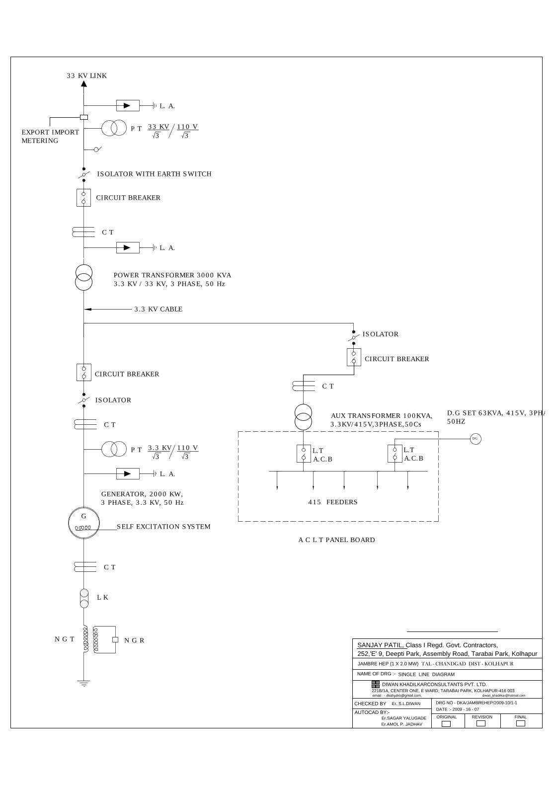
33 KV LINK
L. A.
P T
33 KV
3
110 V
3
ISOLATOR WITH EARTH SWITCH
C T
L. A.
CIRCUIT BREAKER
POWER TRANSFORMER 3000 KVA
3.3 KV / 33 KV, 3 PHASE, 50 Hz
3.3 KV CABLE
ISOLATOR
CIRCUIT BREAKER
C T
L. A.
G
SELF EXCITATION SYSTEM
GENERATOR, 2000 KW,
3 PHASE, 3.3 KV, 50 Hz
C T
L K
N G R
N G T
C T
415 FEEDERS
A C L T PANEL BOARD
D.G SET 63KVA, 415V, 3PHASE,
50HZ
AUX TRANSFORMER 100KVA,
3.3KV/415V,3PHASE,50Cs
ISOLATOR
L.T
A.C.B
L.T
A.C.B
DG
P T
3.3 KV
3
110 V
3
CIRCUIT BREAKER
EXPORT IMPORT
METERING
SINGLE LINE DIAGRAM
NAME OF DRG :-
JAMBRE HEP (1 X 2.0 MW) TAL - CHANDGAD DIST - KOLHAPUR
email : - [email protected],
FINALREVISIONORIGINAL
DATE :- 2009 - 16 - 07
DRG NO - DKA/JAMBREHEP/2009-10/1-1
Er. S.L.DIWANCHECKED BY
Er.SAGAR YALUGADE
Er.AMOL P. JADHAV
AUTOCAD BY:-
252,'E' 9, Deepti Park, Assembly Road, Tarabai Park, Kolhapur
221B/1A, CENTER ONE, E WARD, TARABAI PARK, KOLHAPUR-416 003
DIWAN KHADILKARCONSULTANTS PVT. LTD.
SANJAY PATIL, Class I Regd. Govt. Contractors,