sanitary drainage systems
TRANSCRIPT

SANITARY DRAINAGESYSTEMS

SANITARY DRAINAGE SYSTEMS
• DRAINAGE SYSTEMAll the piping within the private and public premises which conveys sewage, rainwater and other liquid waste to a point of disposal. A drainage system does not include the mains of public sewer systems or a private or a public sewage treatment or disposal plant.

SANITARY DRAINAGE SYSTEMS
• STACKA general term used for any vertical line of soil, waste or vent piping.
• SOIL PIPEA pipe that conveys the discharge of water closets or similar fixtures containing fecal matter, with or without the discharge of other fixtures to the building drain or building sewer.

SANITARY DRAINAGE SYSTEMS
SOIL STACK

SANITARY DRAINAGE SYSTEMS
SANITARY DRAINAGE SYSTEMS
• WASTE PIPEA pipe that conveys only liquid waste free of fecal matter.A waste pipe is generally smaller than a soil pipe because of the nature of matter being discharged into the system.

SANITARY DRAINAGE SYSTEMS
• BRANCHAny part of the piping system other than the main, riser or stack.
• HOUSE DRAINThat part of the lowest horizontal piping of a plumbing system which receives the discharge from soil, waste and other drainage pipes inside a building and conveys it to the building sewer/house sewer.

SANITARY DRAINAGE SYSTEMS
• HOUSE SEWERThat part of the drainage system that extends from the end of the building drain and conveys its discharge to the public sewer, private sewer, individual sewage disposal system, or other appropriate point of disposal.

SANITARY DRAINAGE SYSTEMS

SANITARY DRAINAGE SYSTEMS

SANITARY DRAINAGE SYSTEMS
Privy– The oldest form of disposal of organic waste– It consists of a water tight vault constructed of concrete for the collection of raw sewage and a wooden shelter.– It must be 50’ to 150’ (15m to 45 m) away from the water supply– The vault should be supplied with ventilation– It should be screened and protected from vermin and flies.

SANITARY DRAINAGE SYSTEMS
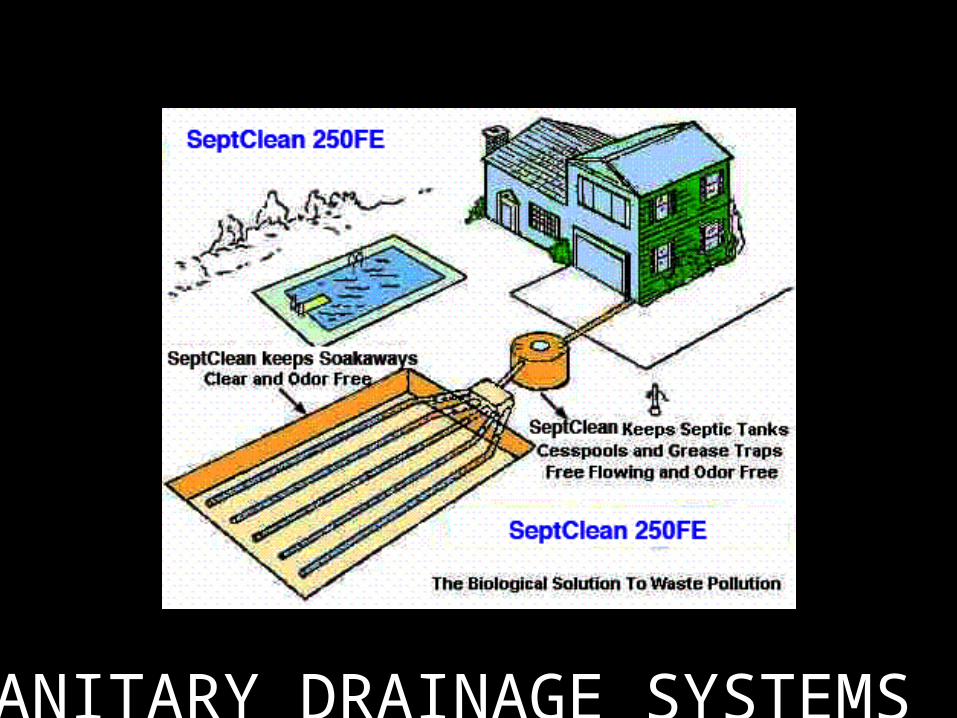
Septic Tank and Seepage Pit
– In this type of sewage disposal, the cycle is completed below ground and within the property. Liquid wastes are purified due to the action of anaerobic bacteria through precipitation in the digestion chamber and effluent is discharged in the leaching chamber by natural percolation.- Effluent –liquid discharge- Scum- non-soluble organic matter that floats on the surface of the sewage- Sludge- organic matter that settles at the base of the septic tank- Size of tank:Residence- 6 persons min capacity of 50 cu ft, and for largerhousehold 5-6 cu. ft/personCommercial, industrial and institutional- 2-3 cu ft/person- Location must be near the structure served:(5’) 1.50 m- water-tight and gas-tight and 50’ –150’ (15m-45m) away from water sources

SANITARY DRAINAGE SYSTEMS
SANITARY DRAINAGE SYSTEMS
SANITARY DRAINAGE SYSTEMS
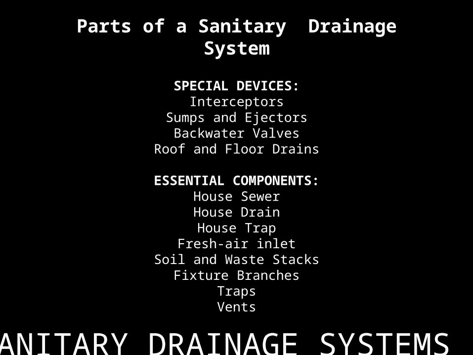
Parts of a Sanitary Drainage System
SPECIAL DEVICES:Interceptors
Sumps and EjectorsBackwater Valves
Roof and Floor Drains
ESSENTIAL COMPONENTS:House SewerHouse DrainHouse Trap
Fresh-air inletSoil and Waste Stacks
Fixture BranchesTrapsVents

SANITARY DRAINAGE SYSTEMS
House Sewer– It extends from the public sewer to the private sewage-disposal tank to the wall of the structure and is entirely outside the building• Glazed vitrified clay – min. 6” –36 “ Ø, 2’-3’ long• Cast-iron min. 4” Ø, 5’ to10’ long• Copper – 12’ to 20’ long• Plastic pipe –10’ to 20’ long
– 12” deep with concrete pavement– 18” deep without concrete covering– Slope at 1/8” or ¼” to the foot

SANITARY DRAINAGE SYSTEMS
House Drain– The horizontal main into which the vertical soil and waste stacks discharge. It connects directly to the house sewer.– Sanitary drain– Leader drain• Copper• Plastic• Extra heavy cast-iron
– Slope at 1/8” or ¼” per foot– A cleanout at the cellar/basement wall is
recommended to clear obstructions– A cleanout at the foot of each waste and soil stack
should be installed

SANITARY DRAINAGE SYSTEMS
Fresh-air inlet– It is intended to admit fresh air to the drainage system so that there will be a free circulation without compressionthroughout the house drain andstacks discharging above the roof– A necessary adjunct to the housetrap

SANITARY DRAINAGE SYSTEMS
Soil and Waste Stacks– The soil and waste stacks collect the sewage from the fixtures throughtheir branches.• Should rest solidly at the bottom onmasonry piers or heavy posts• The upper ends should extend through the roof for ventilation• Made of heavy cast-iron, copper, plastic• Supported at intervals of 10’ with stout wall hangers or brackets or on beams• Min 4” Ø 1’ below the roof• It should be straight free of bends and turns

SANITARY DRAINAGE SYSTEMS
Fixture Branches
– Connect the fixtures with the stacks– Waste or soil branches are connected to the trap of each fixture– 1/8” – ½” per foot– Horizontal branch should not be more than 5’ (from the vertical inlet of the trap to the vent opening– Cast-iron, plastic, copper or galvanized steel
SANITARY DRAINAGE SYSTEMS
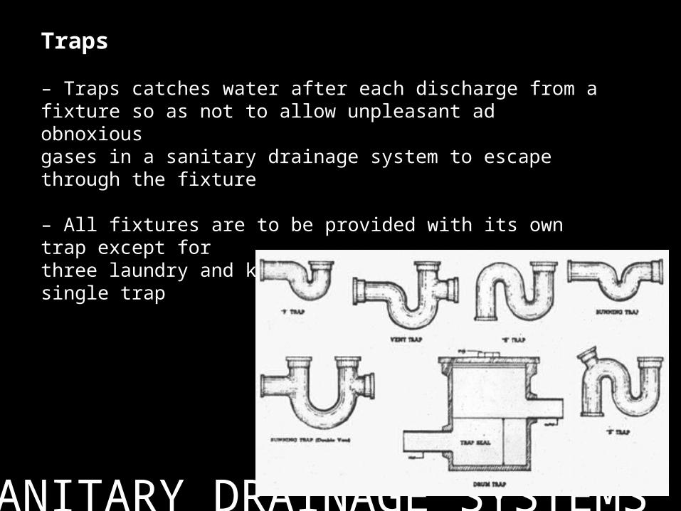
Traps
– Traps catches water after each discharge from afixture so as not to allow unpleasant ad obnoxiousgases in a sanitary drainage system to escapethrough the fixture
– All fixtures are to be provided with its own trap except forthree laundry and kitchen sinks connected to a single trap

SANITARY DRAINAGE SYSTEMS
– Trap seal must have a min depth of 2” and max of 4” depth
– Placed within 2’ of the fixture accessible for cleaning through itsbottom with a plug
– Made of steel, cast-iron, copper, plastic and brass except those in urinals and water closets whichare made of vitreous china cast integrally with the fixture
SANITARY DRAINAGE SYSTEMS
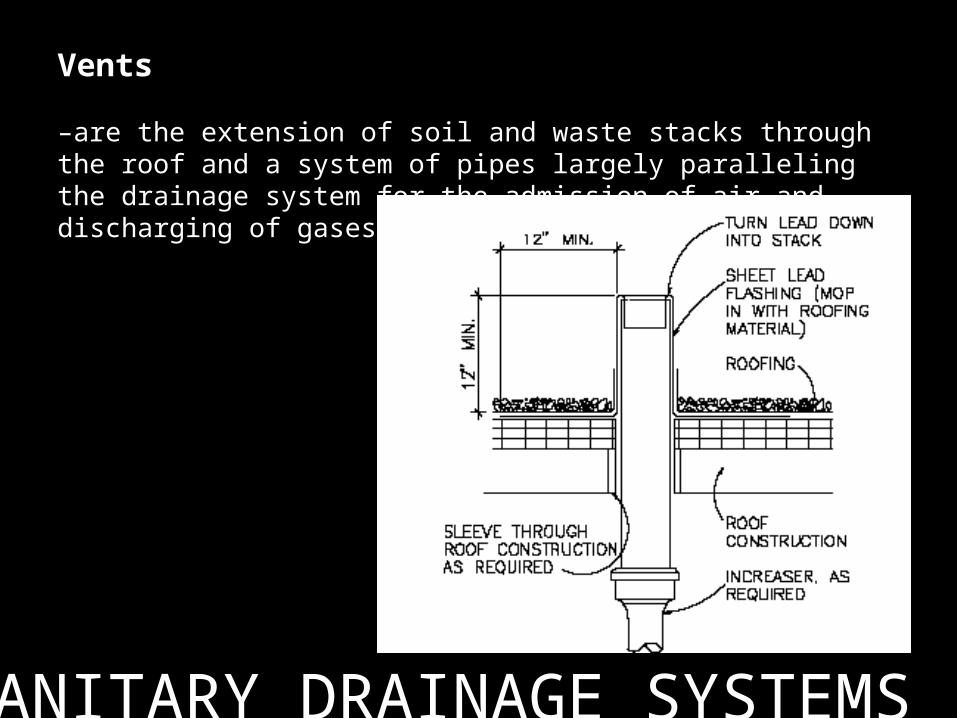
Vents
–are the extension of soil and waste stacks through the roof and a system of pipes largely paralleling the drainage system for the admission of air and discharging of gases.

SANITARY DRAINAGE SYSTEMS

SANITARY DRAINAGE SYSTEMS
SANITARY DRAINAGE SYSTEMS
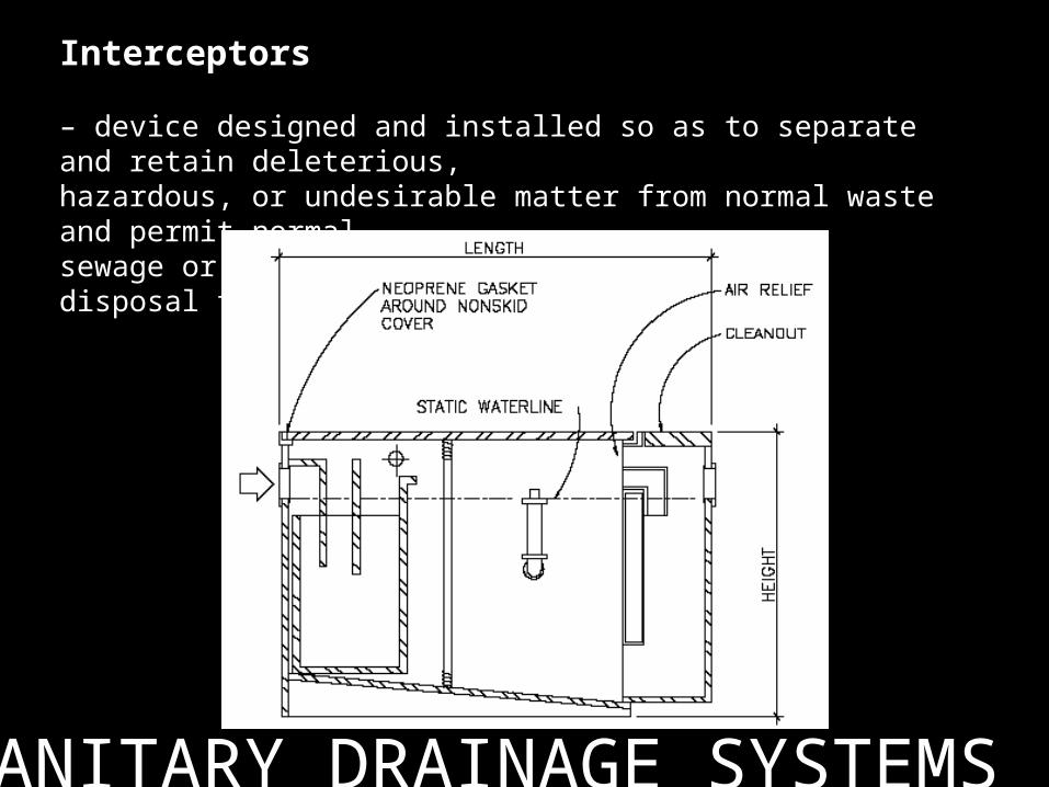
Interceptors
– device designed and installed so as to separate and retain deleterious,hazardous, or undesirable matter from normal waste and permit normalsewage or liquid waste to discharge into the disposal terminal by gravity.
SANITARY DRAINAGE SYSTEMS
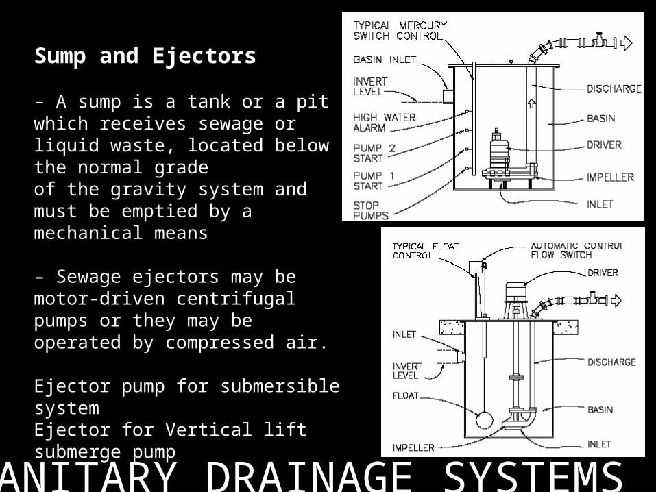
Sump and Ejectors
– A sump is a tank or a pit which receives sewage or liquid waste, located below the normal gradeof the gravity system and must be emptied by a mechanical means
– Sewage ejectors may be motor-driven centrifugal pumps or they may be operated by compressed air.
Ejector pump for submersible systemEjector for Vertical lift submerge pump

SANITARY DRAINAGE SYSTEMS
Backwater valves/check valve– A backwater valve closes to prevent reverseflow from a sewer to low facilities when thereis a heavy drainage load for short periods thatcan cause building up and over flow of wastes.
Roof Drain– Is a receptacle designed to collect surface or rain water from an open area and discharge to a catch basin.
Floor Drain– Is any pipe which carries water or waterborne wastes in a building drainage system.

SANITARY DRAINAGE SYSTEMS
SANITARY DRAINAGE SYSTEMS
Is that portion of the drainage installationdesigned to maintain atmospheric pressurewithin it• and prevent at least three major difficulties:– Retardation of flow– Material deterioration– Trap seal loss
Retardation of flow.• The result of improper atmospheric conditions, because ofinsufficient ventilation or incorrect installation of fittings.• Increased pressure causes retarded flow in the vertical stackand also affects the discharge capacity of its branchesMaterial deterioration.• Wastes create chemical compounds of an acid nature whichdeteriorates the piping system. Objectionable gases should beeliminated by proper ventilation.Trap seal loss.• Attributed to inadequate ventilation of the trap and thesubsequent minus and plus pressure which occur

SANITARY DRAINAGE SYSTEMS
• Five ways in which trap seal is lost:– Siphonage (direct or indirect)– Back Pressure– Capillary Attraction– Evaporation– Wind Effect
Siphonage is the result of a minus pressure in the drainage system
– Direct siphonage/selfsiphonage is common in unventilated traps which serve oval-shaped fixtures (lavatories, small slop sink)
– Indirect siphonage or siphonage by momentum is the result of a minus
pressure in the waste piping caused by discharge of water from a fixture installed on a line which serves a fixture placed at a lower elevation. No possibility of re-seal.
SANITARY DRAINAGE SYSTEMS
Back-pressure is caused by a plus pressure in large plumbing installations.– The fixtures in which it occurs are usually located at the base of a soil stack or where soil pipe changes its direction.– Ventilate the base of the soil pipe to correct this condition.
Capillary attraction, trap seal is caused by suspension of foreign object (rag, string, lint, hair) into the trap seal extending over the outlet arm of the trap.– The object serves as an absorbing siphon.
Evaporation of the trap seal is a phenomenon of nature.– The atmosphere absorbs moisture and varies inversely with temperature.– It requires weeks to evaporate trap seal– Deep seal traps are recommended when air is not saturated with moisture.

SANITARY DRAINAGE SYSTEMS
Wind effects– Wind of high velocity passing over the top of the soil pipe roof terminalaffects trap seal.– Downdrafts tends to ripple the liquid content of the trap and spill quantity of it over its outlet leg into the system.– Soil vent terminals should be away from valleys, gables, abrupt projections of the roof where wind can strike and be directed to theterminal.
Main Soil and WasteVent– Is that portion of the soil pipe stack above the highest installed fixture branch extending through the roof .– The same diameter as the water-carrying portion of the soil or waste pipe• (2”-4” Ø )

SANITARY DRAINAGE SYSTEMS
Main Vent– Is that portion of the vent pipe system which serves as a terminal for the smaller, tributary forms of individual and group fixture trap ventilation (collecting vent line)– It begins at the base of the soil-pipe stack to relieve it from back pressure and terminates in the soil –pipe stack 3’ above the highestfixture branch.
Individual Vent/back vent– It serves a single trap.– Reconnected to the main vent above the overflow line of the fixture it serves.– Not applied when fixtures are closely grouped.

SANITARY DRAINAGE SYSTEMS
Unit Vent– It ventilates two fixture traps that discharge into a sanitary cross withdeflectors.– Is used on two fixtures of similar design installed on opposite sides of the partition.– For apartment and hotel toilets.
Circuit or Loop Vent
– Circuit vent serves two or more fixture traps that discharge into a horizontal soil or waste branch extended at slight grade battery of fixtures.– The Code allows a maximum of 8 fixture/horizontal branch.– Supported by a relief vent at the between the last fixture and the main vent.

SANITARY DRAINAGE SYSTEMS
Relief Vent
– It primarily eliminates minus and plus pressures in the drainage system– It ventilates the soil and waste pipe and connecting branches rather than the fixture trap– Commonly used in connection with waste branches which are circuited – Prevents back-pressure at the base of a soil-pipe stack– Referred to as yoke or bypass vent at 3 to 5 floor intervals.
Looped Vent
– used on fixtures which are located in the room away from partitions that might be utilized to conceal the waste and vent– A bleeder or drip connection must be made between the waste pipe andthe lowest point of the vent line to avoid accumulation of water in the loop vent.

SANITARY DRAINAGE SYSTEMS
Wet Vent– a wet vent is a method ofventilation used rather extensively for small groups of bathroomfixtures– A portion of the vent system through which liquid wastes flow
Local Vent– a vent without connection with the plumbing system– It terminates at the roof and connected to thefixture at point below the seat
Utility vent – Used for undergroundpublic restrooms
SANITARY DRAINAGE SYSTEMS
Questions?

SANITARY DRAINAGE SYSTEMS
THANK YOU FOR LISTENING!!