sand dgremoval handling cleaning.pdf
DESCRIPTION
gfTRANSCRIPT
1
Cyclone- and Vessel-based Technologies
for
Solids/Sludge Removal, Handling & Cleaning
Report Ref.: D0904-013-REP1 Rev.2
Date: 15-Nov-11
Prepared by: Willem de Waard Checked by: Danny Thierens
ASCOM BV
Simon Stevinweg 27
6827 BS Arnhem
The Netherlands
ADVANCED SEPARATION COMPANY BV
INNOVATIVE AND RELIABLE SOLUTIONS TO
IMPROVE PROCESS SYSTEMS

2
Table of Contents
1 SOLIDS/SLUDGE PRODUCTION .............................................................................................................................. 3
1.1 TYPES OF PRODUCED SOLIDS/SLUDGE .................................................................................................................................. 3
2 REMOVAL TECHNOLOGIES & LOCATIONS .............................................................................................................. 4
2.1 TECHNOLOGIES ................................................................................................................................................................ 4
2.2 LOCATIONS ...................................................................................................................................................................... 5
2.2.1 Location 1 – Downstream of Well Head ...................................................................................................................... 6
2.2.2 Location 2 – Upstream of Separator ............................................................................................................................ 7
2.2.3 Location 3 – Separator ................................................................................................................................................. 8
2.2.4 Location 4 – Oil Outlet Line of Separator ..................................................................................................................... 9
2.2.5 Location 5 – Water Outlet Line of Separator ............................................................................................................. 10
2.2.6 Location 6 – Slurry Drain Line of Separator ............................................................................................................... 10
2.2.7 Location 7 – Upstream of Produced Water System ................................................................................................... 10
3 VESSEL-BASED REMOVAL .....................................................................................................................................11
3.1 INTRODUCTION .............................................................................................................................................................. 11
3.2 METHODS OF SOLIDS REMOVAL FROM A VESSEL ................................................................................................................... 13
3.2.1 Manual removal ........................................................................................................................................................ 13
3.2.2 Fluidising solids by spraying water and draining the slurry ....................................................................................... 13
3.2.3 Fluidising solids by rotating water and hydraulically removing the slurry ................................................................ 16
3.3 ASCOM HIPER SOLUTION ............................................................................................................................................... 18
4 CYCLONE-BASED REMOVAL ..................................................................................................................................19
4.1 INTRODUCTION .............................................................................................................................................................. 19
4.2 DESANDER TYPES............................................................................................................................................................ 19
4.2.1 Type 1 – Multi Phase Desander (Conventional) ......................................................................................................... 19
4.2.2 Type 2 – Multi Phase Desander (Advanced) .............................................................................................................. 20
4.2.3 Type 3 – Single Phase Desander (Advanced, d>50 micron) ....................................................................................... 21
4.2.4 Type 4 – Single Phase Desander (Conventional, d<50 micron) .................................................................................. 22
4.2.5 Type 5 – Single Phase Desander (Conventional, high load) ....................................................................................... 22
4.2.6 Type 6 – Single Phase Desander (Advanced, high load) ............................................................................................ 22
5 HANDLING ...........................................................................................................................................................23
5.1 INTRODUCTION .............................................................................................................................................................. 23
5.1.1 Manual removal ........................................................................................................................................................ 23
5.1.2 Drainage into big bag ................................................................................................................................................ 23
5.1.3 Online removal .......................................................................................................................................................... 24
6 CLEANING ............................................................................................................................................................26

3
1 Solids/sludge Production
1.1 Types of Produced Solids/Sludge
Solids/sludge is a natural and an induced by-product of oil and gas production. The solids/sludge produced
consists of four types:
1) Drilling solids/sludge (drilling mud, cement, etc.)
2) Natural reservoir solids/sludge (sand, clay, etc.)
3) Induced reservoir solids/sludge (fracturing sand, gravel pack, etc.)
4) Corrosion products
Drilling Solids/sludge
Drilling solids/sludge such as drilling mud and cement are used during the drilling and completion of the well
to provide a static head such that the well cannot blow-out and to seal the production pipe to the reservoir
structure, respectively. During those operations drilling solids/sludge will be spilled into the well when the
drilling bit reaches the reservoir. Some of these solids/sludge may leave the well again during the initial testing
of the well. However, some of this material may still be produced when the commercial production starts.
Natural reservoir solids/sludge
The natural reservoir solids/sludge are produced naturally. The particle sizes of these solids/sludge is typically
small to medium, up to 2000 m and a concentration anywhere between 5 and 30,000 ppm(v) under peak
conditions. When solids/sludge are produced from the start, this may be at an initial high production rate,
which then declines to a lower level of continuous solids/sludge production. Alternatively, when solids/sludge
are produced with the start of produced water production, the solids/sludge production rate is likely to
increase with the increase of the produced water production rate. Subject to the reservoir and well behavior,
solids/sludge slugs may occur.
Induced reservoir solids/sludge
Induced reservoir solids are solids/sludge that are being produced after a well has been worked-over, the
solids-restraining down-hole gravel pack has collapsed or the reservoir has been fractured to release the
hydrocarbon volumes of oil & gas contained in pockets in to the main reservoir such that they can be
accessed/extracted. The size of the solids/sludge that typically are produced as a result of fracturing is up to
2000 m and a concentration of up to 10,000 ppm(v). However, when the down-hole gravel pack erodes or
collapses, the particle sizes may be up to 3500 m.
Corrosion Products
Corrosion products are the most difficult to predict in terms of size and quantity, however, their size ranges
anywhere from 10 to 10000 m. Therewith they pose the greatest risk with respect to blockage.
4
2 Removal Technologies & Locations
2.1 Technologies
Because of the abrasive nature of the solids/sludge, the lifetime of subsea piping and (choke) valves and
downstream equipment and instrumentation is greatly affected and the cost implication to replace such
equipment is significant. The solids/sludge can be removed from the process streams by three methods:
1) Sand traps
2) Cyclone-based desanding equipment
3) Vessel-based desanding equipment
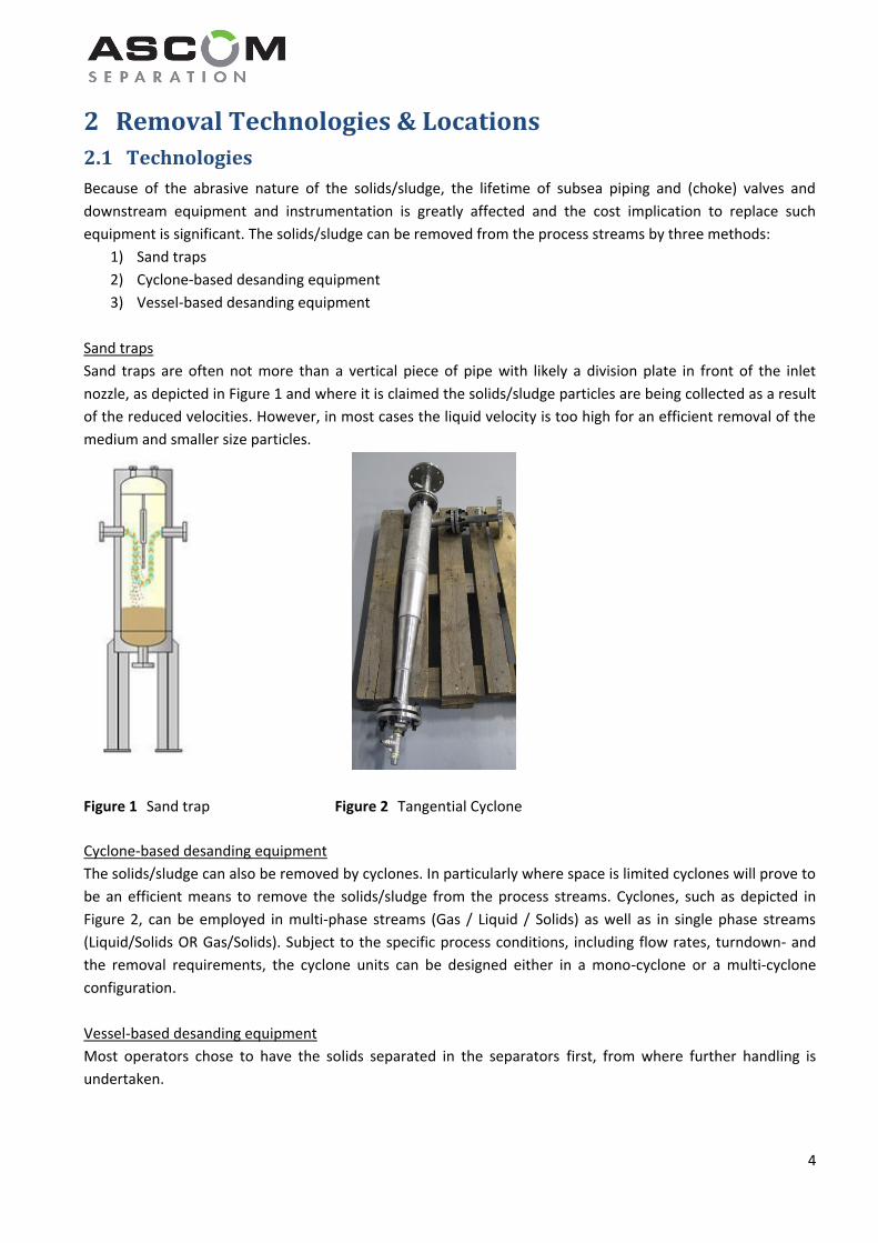
Sand traps
Sand traps are often not more than a vertical piece of pipe with likely a division plate in front of the inlet
nozzle, as depicted in Figure 1 and where it is claimed the solids/sludge particles are being collected as a result
of the reduced velocities. However, in most cases the liquid velocity is too high for an efficient removal of the
medium and smaller size particles.
Figure 1 Sand trap Figure 2 Tangential Cyclone
Cyclone-based desanding equipment
The solids/sludge can also be removed by cyclones. In particularly where space is limited cyclones will prove to
be an efficient means to remove the solids/sludge from the process streams. Cyclones, such as depicted in
Figure 2, can be employed in multi-phase streams (Gas / Liquid / Solids) as well as in single phase streams
(Liquid/Solids OR Gas/Solids). Subject to the specific process conditions, including flow rates, turndown- and
the removal requirements, the cyclone units can be designed either in a mono-cyclone or a multi-cyclone
configuration.
Vessel-based desanding equipment
Most operators chose to have the solids separated in the separators first, from where further handling is
undertaken.

5
2.2 Locations
Various locations can be identified where the solids/sludge can be removed from the production process. The
earlier the solids/sludge are removed from the process, the more beneficial this will be. The locations
identified are shown in Figure 1 and listed below:
1. Downstream of well head
2. Upstream of separator
3. Separator(s)
4. Oil outlet line separator
5. Water outlet line separator
6. Sandjetting system drain line
7. Upstream of Produced Water Treatment System
Figure 3 Various locations where solids/sludge can be removed
The process flow streams depicted in Figure 3 for the 1st Stage Separator represent other separators that may
be present more downstream in the process. When sand is expected in those locations as well, similarly as
depicted above, desanders can be integrated in the process.
1st Stage
3-Ph Separation
Oil
Stabilisation
Produced
Water
Treatment
De
sa
nd
er
Choke
Choke
Location 1 / Type 1 or 2 Location 2 / Type 1 or 2
Location 4 / Type 3 or 4Location 6 / Type 5 or 6
Location 7 / Type 3 or 4
De
sa
nd
er
Choke
Location 1 / Type 1 or 2
De
sa
nd
er
Choke
De
sa
nd
er
De
sa
nd
er
De
sa
nd
er
De
sa
nd
er
Location 5 / Type 3 or 4
Choke
No Desander
Required
No Desander
Required
No Desander
Required
Gas
Treatment
Location 3

6
In Figure 3 above for the various locations in the process (all, except Location 3), also various cyclone-based
desanders have been identified. The types are:
1. Multi phase desander (Conventional Type)
2. Multi phase desander (Advanced Type)
3. Single phase desander (Advanced Type, d > 50 micron)
4. Single phase desander (Conventional Type, d < 50 micron)
5. Single phase desander (Conventional Type, high load)
6. Single phase desander (Advanced Type, high load)
2.2.1 Location 1 – Downstream of Well Head
Apart from sand screens or gravel packs installed in the reservoir itself, the first and most preferred external
location to remove the produced solids/sludge is downstream of the well head. The reason for this being that
the earlier the solids/sludge are being removed from the fluids, the better this is for the longlivety of the
pipelines and everything that comes downstream.
In the event the well head is located subsea, although technically feasible, cost-wise subsea solids/sludge
removal as a standalone operation is very likely not attractive. Except in a situation where subsea Gas/Liquid
separation is economically attractive, the desanding equipment could be integrated on the subsea process
module as shown in Figure 4. Even then it remains to be evaluated how and where the collected solids/sludge
will be disposed as most re-injection wells may not be able to receive the solids/sludge due to the risk of
potential blockage of the reservoir pores.
Figure 4 Various sub-sea locations where solids/sludge can be removed
Subsea Separator
Topside Oil
Treatment
Water
Injection
De
sa
nd
er
Choke
Choke
Location 1 / Type 1 or 2 Location 2 / Type 1 or 2
Location 6 / Type 5 or 6
De
sa
nd
er
Choke
Location 1 / Type 1 or 2
De
sa
nd
er
Choke
No Desander
Required
No Desander
Required
Topside Gas
Treatment
Location 3
De
sa
nd
er

7
The most convenient location for the desanding equipment is therewith on the topsides facilities of which the
possible locations are shown in Figure 3. Provided that the choke valve is on the topsides located as well, the
preferred location is upstream thereof as these devices suffer significantly from erosion by solids/sludge. As
the desanding equipment in that case needs to be fully rated to the well pressure, the technical challenge is
that at some point in time the collected sand will need to be brought to atmospheric conditions for cleaning
and disposal.
This can be done in a batch-wise operation whereby the Solids/Sludge Accumulator is properly isolated from
the main desanding equipment and the pressure is relieved under an adequate procedure. For the duration of
this procedure and the re-pressurising of the Solids/Sludge Accumulator, the desanding equipment will need
to contain sufficient hold-up volume for the solids/sludge that are being collected during this time.
In view of the solids/sludge produced, as discussed in Paragraph 1.1, it is of importance to design any
desanding equipment robust enough to specifically deal with potential solids/sludge slugs and large particles.
If so required, in a second stage more sophisticated desanding cyclone technology can be applied to separate
the finer solids/sludge particles.
2.2.2 Location 2 – Upstream of Separator
The second location where desanding equipment can be installed is upstream of the 1st Stage Separator. It
receives the combined well fluids at a reduced pressure. As can be taken from Figure 5, such location may not
always have a large plot space available and hence a compact design is essential for a successful execution of
the brownfield modifications.
Figure 5 Proposed installation location of desanding equipment on a FPSO
Proposed Installation
Location of Desander
Vessel
1st Stage
Separator
8
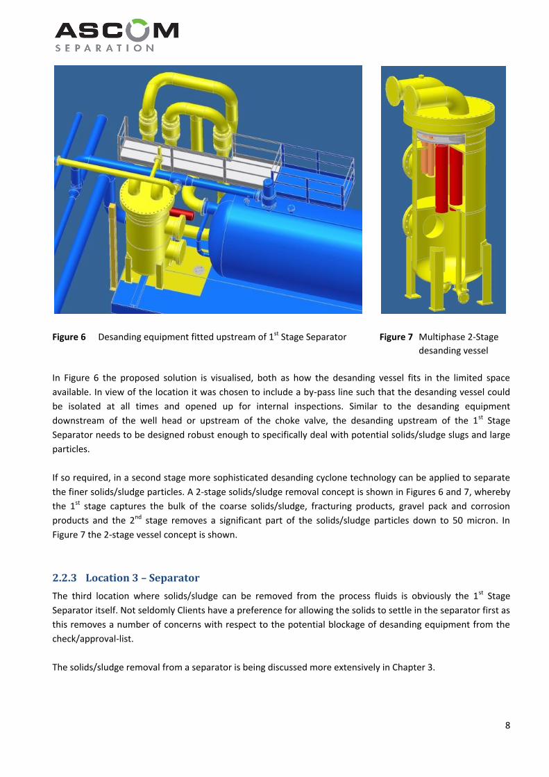
Figure 6 Desanding equipment fitted upstream of 1st Stage Separator Figure 7 Multiphase 2-Stage
desanding vessel
In Figure 6 the proposed solution is visualised, both as how the desanding vessel fits in the limited space
available. In view of the location it was chosen to include a by-pass line such that the desanding vessel could
be isolated at all times and opened up for internal inspections. Similar to the desanding equipment
downstream of the well head or upstream of the choke valve, the desanding upstream of the 1st Stage
Separator needs to be designed robust enough to specifically deal with potential solids/sludge slugs and large
particles.
If so required, in a second stage more sophisticated desanding cyclone technology can be applied to separate
the finer solids/sludge particles. A 2-stage solids/sludge removal concept is shown in Figures 6 and 7, whereby
the 1st stage captures the bulk of the coarse solids/sludge, fracturing products, gravel pack and corrosion
products and the 2nd stage removes a significant part of the solids/sludge particles down to 50 micron. In
Figure 7 the 2-stage vessel concept is shown.
2.2.3 Location 3 – Separator
The third location where solids/sludge can be removed from the process fluids is obviously the 1st Stage
Separator itself. Not seldomly Clients have a preference for allowing the solids to settle in the separator first as
this removes a number of concerns with respect to the potential blockage of desanding equipment from the
check/approval-list.
The solids/sludge removal from a separator is being discussed more extensively in Chapter 3.

9
2.2.4 Location 4 – Oil Outlet Line of Separator
The fourth type of solids/sludge removing location is the oil outlet line of the upstream separator, upstream of
the liquid level control valve. Solids/sludge are expected to carryover from the separator when:
1) Particles are larger than the particle cut size that theoretically can be separated by gravity
a. Poor liquid distribution in separator
b. Higher emulsion viscosity
2) Particles are smaller than the particle cut size that theoretically can be separated by gravity
a. Small particle sizes / solid fines
b. High hydrocarbon liquid viscosity
3) Excessive solids/sludge build-up
a. Solids/sludge removal system not used (frequently)
b. No solids removal system installed
c. No solids production anticipated (and no solids removal system installed)
When solids carry over unnoticed or in excessive quantities this is likely to have a significant effect with
respect to erosion and fouling of the downstream equipment such as heat exchangers, valves, instrumentation
and which even can lead to complete blockage of the piping, as shown in Figure 8.
Figure 8 Blocked pipeline
10
2.2.5 Location 5 – Water Outlet Line of Separator
The fifth type of solids/sludge removing location is the water outlet line of the upstream separator, upstream
of the interface level control valve. Solids/sludge are expected to carryover from the separator when:
1) Particles are larger than the particle cut size that theoretically can be separated by gravity
a. Poor liquid distribution in separator
2) Particles are smaller than the particle cut size that theoretically can be separated by gravity
a. Small particle sizes / solid fines
3) Excessive solids/sludge build-up
a. Solids/sludge removal system not used (frequently)
b. No solids removal system installed
c. No solids production anticipated (and no solids removal system installed)
When solids carry over unnoticed or in excessive quantities this is likely to have a significant effect with
respect to erosion and fouling of the downstream equipment such as heat exchangers, valves, instrumentation
and which even can lead to complete blockage of the piping.
2.2.6 Location 6 – Slurry Drain Line of Separator
The sixth type of solids/sludge removing location is in the slurry drain line of the separator. When operating
the sandjetting system in a separator, the solids/sludge needs to be removed again from the produced water
used to get it entrained in. Especially in the first few minutes the sandjetting system is operated, the
solids/sludge concentration is relatively high and typically too high for conventional types of desanding
cyclones available in the market. In order to bridge this technology gap, ASCOM has designed and developed a
desanding cyclone system specifically for this application.
The produced water used to fluidise the solids/sludge, subsequently needs to be treated to reduce the oil in
water quantity. Various de-oiling technologies are available for this purpose, subject to the operating pressure.
2.2.7 Location 7 – Upstream of Produced Water System
The seventh type of solids/sludge removing location is upstream of the Produced Water System. This is to
protect the de-oiling hydrocyclones in particular from erosion.
When operating the sandjetting system in a separator, the solids/sludge needs to be removed again from the
produced water used to get it entrained in. Especially in the first few minutes the sandjetting system is
operated, the solids/sludge concentration is relatively high and typically too high for conventional types of
desanding cyclones available in the market. In order to dilute the slurry, it is re-combined with the Produced
Water coming straight from the separator.
The produced water is routed through desanding cyclones installed in this location and subsequently through de-oiling hydrocyclones to reduce the oil in water quantity.
11
3 Vessel-based Removal
3.1 Introduction
In view of the fact that it is most common in the industry to allow the solids/slurry to enter the separator first,
the concepts of vessel-based removal are discussed at this point. In Chapter 4 the various cyclone-based
removal technologies will be discussed.
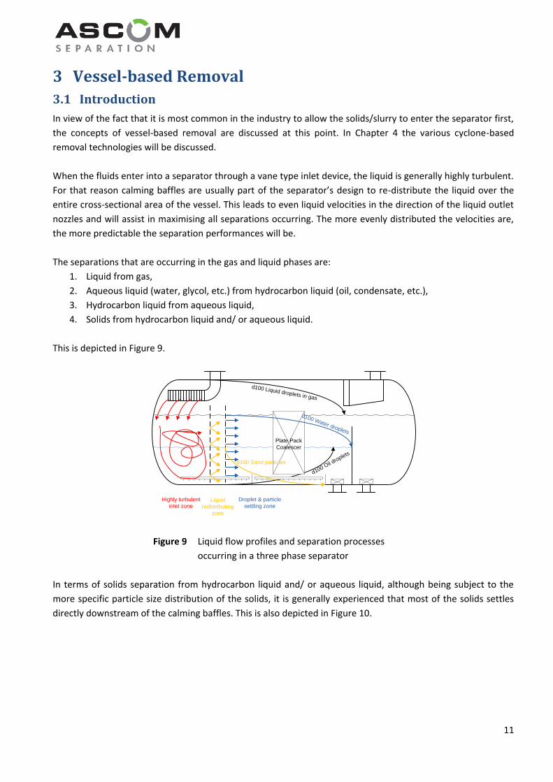
When the fluids enter into a separator through a vane type inlet device, the liquid is generally highly turbulent.
For that reason calming baffles are usually part of the separator’s design to re-distribute the liquid over the
entire cross-sectional area of the vessel. This leads to even liquid velocities in the direction of the liquid outlet
nozzles and will assist in maximising all separations occurring. The more evenly distributed the velocities are,
the more predictable the separation performances will be.
The separations that are occurring in the gas and liquid phases are:
1. Liquid from gas,
2. Aqueous liquid (water, glycol, etc.) from hydrocarbon liquid (oil, condensate, etc.),
3. Hydrocarbon liquid from aqueous liquid,
4. Solids from hydrocarbon liquid and/ or aqueous liquid.
This is depicted in Figure 9.
Figure 9 Liquid flow profiles and separation processes
occurring in a three phase separator
In terms of solids separation from hydrocarbon liquid and/ or aqueous liquid, although being subject to the
more specific particle size distribution of the solids, it is generally experienced that most of the solids settles
directly downstream of the calming baffles. This is also depicted in Figure 10.
d100 Oil d
roplets
Highly turbulent
inlet zoneLiquid
redistributing
zone
Droplet & particle
settling zone
d100 Liquid droplets in gas
Plate Pack
Coalescer
d100 Water droplets
d100 Sand particles

12
Figure 10 Solids accumulation in a three phase separator
Over the production time the solids will build up in the vessel and in three phase separators this eventually will
start adversely affecting the oil from water separation performance. Firstly by taking up a volume which
otherwise would be available for aqueous liquid flow, which increases the aqueous liquid velocities in the
remainder of the volume. As an immediate result thereof, the hydrocarbon droplet d100% cut size separated will
increase and therewith the OIW carryover content.
Secondly, in the event a plate pack coalescer is installed in the separator to enhance the liquid-liquid
separation performance, solids will settle and, over time, build-up from the bottom within the plate pack
arrangement. When this happens, obviously the performance will be affected, but more importantly it will
lead to down time as the plate pack boxes will likely need to be removed from the vessel for removing the
solids settled between the plates.
With an increasing solids volume present in the separator, the solids also will start carrying over to the
downstream equipment and subsequently the effects of erosion will be noticed on (control) valves,
instrumentation, heat exchangers, rotating equipment (centrifuges, pumps), hydrocyclones and other
equipment that is sensitive to the abrasive nature of the solids or is susceptible for plugging.
In both two and three phase separators the interaction of the stagnant solids layer with the liquid may result
in a so-called “cementing effect”, whereby over time the solids particles agglomerate into a solid mass. It will
be very difficult to either fluidise or remove this solid mass from the vessel and eventually may need to be
removed by shovel.
It is therefore stressed that the solids must be removed from the separators on a regular basis!
Highly turbulent
inlet zoneLiquid
redistributing
zone
Droplet & particle
settling zone
Plate Pack
Coalescer NIL
LLIL
LIL
NIL
LLIL
LIL
View A-A
A
A
Lower part of Plate Pack
Coalescer critical for
Oil from Water separation
Sand accumulation
13
3.2 Methods of Solids Removal from a Vessel
Presently three ways of removing solids from a vessel exist:
1. Manual removal
2. Fluidising solids by spraying water and draining the slurry
3. Fluidising solids by rotating water and hydraulically removing the slurry.
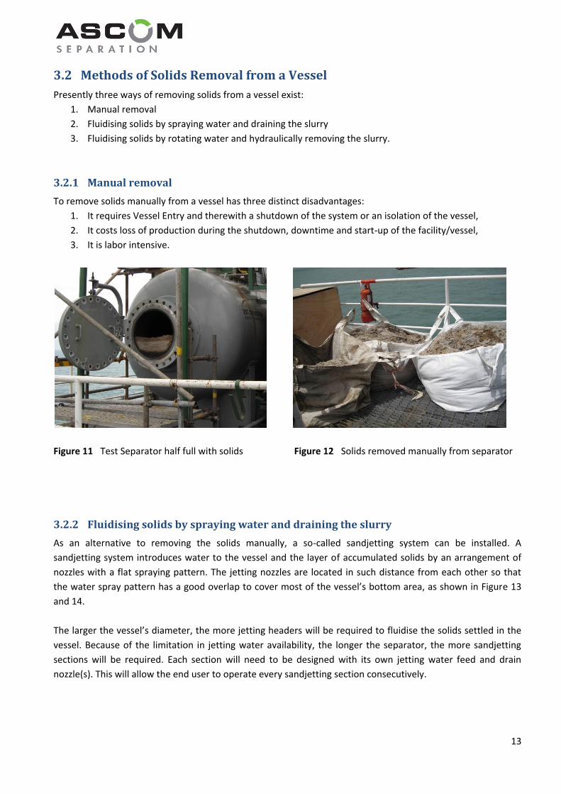
To remove solids manually from a vessel has three distinct disadvantages:
1. It requires Vessel Entry and therewith a shutdown of the system or an isolation of the vessel,
2. It costs loss of production during the shutdown, downtime and start-up of the facility/vessel,
3. It is labor intensive.
Figure 11 Test Separator half full with solids Figure 12 Solids removed manually from separator
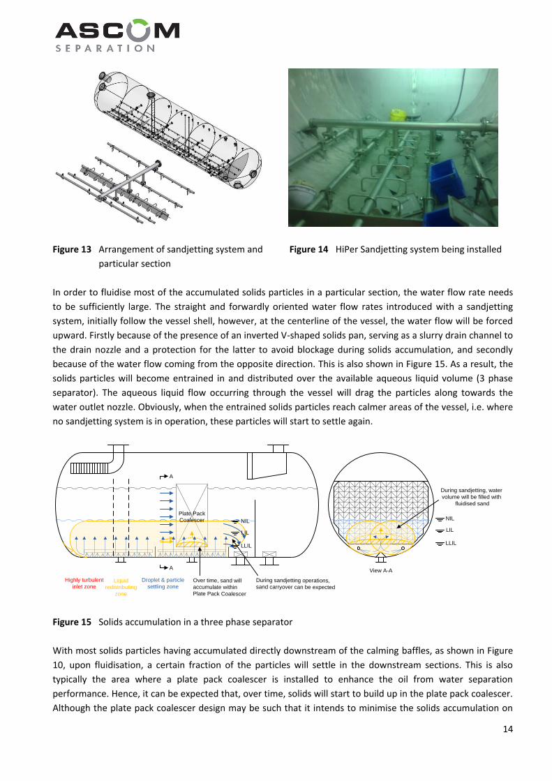
As an alternative to removing the solids manually, a so-called sandjetting system can be installed. A
sandjetting system introduces water to the vessel and the layer of accumulated solids by an arrangement of
nozzles with a flat spraying pattern. The jetting nozzles are located in such distance from each other so that
the water spray pattern has a good overlap to cover most of the vessel’s bottom area, as shown in Figure 13
and 14.
The larger the vessel’s diameter, the more jetting headers will be required to fluidise the solids settled in the
vessel. Because of the limitation in jetting water availability, the longer the separator, the more sandjetting
sections will be required. Each section will need to be designed with its own jetting water feed and drain
nozzle(s). This will allow the end user to operate every sandjetting section consecutively.
3.2.1 Manual removal
3.2.2 Fluidising solids by spraying water and draining the slurry
14
Figure 13 Arrangement of sandjetting system and Figure 14 HiPer Sandjetting system being installed
particular section
In order to fluidise most of the accumulated solids particles in a particular section, the water flow rate needs
to be sufficiently large. The straight and forwardly oriented water flow rates introduced with a sandjetting
system, initially follow the vessel shell, however, at the centerline of the vessel, the water flow will be forced
upward. Firstly because of the presence of an inverted V-shaped solids pan, serving as a slurry drain channel to
the drain nozzle and a protection for the latter to avoid blockage during solids accumulation, and secondly
because of the water flow coming from the opposite direction. This is also shown in Figure 15. As a result, the
solids particles will become entrained in and distributed over the available aqueous liquid volume (3 phase
separator). The aqueous liquid flow occurring through the vessel will drag the particles along towards the
water outlet nozzle. Obviously, when the entrained solids particles reach calmer areas of the vessel, i.e. where
no sandjetting system is in operation, these particles will start to settle again.
Figure 15 Solids accumulation in a three phase separator
With most solids particles having accumulated directly downstream of the calming baffles, as shown in Figure
10, upon fluidisation, a certain fraction of the particles will settle in the downstream sections. This is also
typically the area where a plate pack coalescer is installed to enhance the oil from water separation
performance. Hence, it can be expected that, over time, solids will start to build up in the plate pack coalescer.
Although the plate pack coalescer design may be such that it intends to minimise the solids accumulation on
NIL
LLIL
LIL
View A-A
During sandjetting, water
volume will be filled with
fluidised sand
Highly turbulent
inlet zoneLiquid
redistributing
zone
Droplet & particle
settling zone
NIL
LLIL
A
A
Plate Pack
Coalescer
Over time, sand will accumulate within Plate Pack Coalescer
LIL
During sandjetting operations, sand carryover can be expected

15
the parallel plates itself, in the end, all solids will travel downward. Subject to the specific arrangement,
potentially a lot of the solids separated in the plate pack coalescer may be accumulating in the centre, where it
may prove difficult to be removed and then accumulation over time will be a fact. This is also shown in Figure
15.
As the sandjetting sections will likely be operated consecutively for about 15 – 30 minutes each, each section
will result in solids carryover to the downstream sections and the water outlet nozzle. Subject to the particle
size distribution and the removal efficiency of the slurry by drainage, during the period of time the sandjetting
sections are being operated, the downstream equipment may see quite a considerable solids entrainment in
the produced water.
It is for the end user to determine whether the intermittent operation of the sandjetting system, and the
associated solids carryover, poses a threat to the stability, reliability and operational continuity of the
downstream equipment!
In any case, the big advantage of a sandjetting system is that the entire vessel’s bottom can be covered and
that the removal efficiency therewith can be very high.
The incidental risks, that should not be overseen, are the following:
1. Water is required from a clean source as jetting nozzles can easily block and affect the fluidisation rate
and therewith the removal efficiency,
2. When a jetting or flushing nozzle is pointing towards vessel’s shell, it can turn into a solids blast system
and causing severe erosion to the vessel’s shell.
Item number one is a continued concern and is inherent to using spraying nozzles. Provided a clean water
source is being used and the sandjetting system is inspected along with regular internal vessel inspections, the
effect a single or a few blocked nozzle(s) may have on the performance of the entire system could be kept to a
limit. Performance indicators such as Oil in Water quantity and solids accumulation in downstream (pump)
strainers can be an indication of excessive solids accumulation in the separator and should not be ignored.
Item number is very much related to the particular mechanical design of the sandjetting system. ASCOM has
developed a design that avoids these effects.
It is remarked that many vendors and suppliers design and supply a wide variety of sparging and sandjetting
systems, however, often these consist of not more than a pipe with holes or a header with small pipes with
their end’s flattened. It is brought to the reader’s attention that such devices are malicious as in no way the
water flow rate or the water spraying angle can be evenly distributed and controlled consistently over all
spraying points. This will lead to solids not being fluidised in all areas and hence such systems are likely not to
achieve the desired solids removal efficiency from the vessel.
16
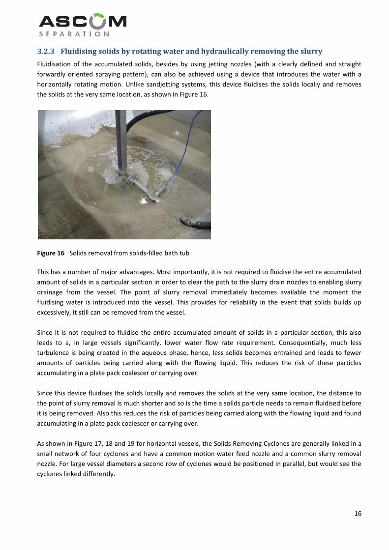
Fluidisation of the accumulated solids, besides by using jetting nozzles (with a clearly defined and straight
forwardly oriented spraying pattern), can also be achieved using a device that introduces the water with a
horizontally rotating motion. Unlike sandjetting systems, this device fluidises the solids locally and removes
the solids at the very same location, as shown in Figure 16.
Figure 16 Solids removal from solids-filled bath tub
This has a number of major advantages. Most importantly, it is not required to fluidise the entire accumulated
amount of solids in a particular section in order to clear the path to the slurry drain nozzles to enabling slurry
drainage from the vessel. The point of slurry removal immediately becomes available the moment the
fluidising water is introduced into the vessel. This provides for reliability in the event that solids builds up
excessively, it still can be removed from the vessel.
Since it is not required to fluidise the entire accumulated amount of solids in a particular section, this also
leads to a, in large vessels significantly, lower water flow rate requirement. Consequentially, much less
turbulence is being created in the aqueous phase, hence, less solids becomes entrained and leads to fewer
amounts of particles being carried along with the flowing liquid. This reduces the risk of these particles
accumulating in a plate pack coalescer or carrying over.
Since this device fluidises the solids locally and removes the solids at the very same location, the distance to
the point of slurry removal is much shorter and so is the time a solids particle needs to remain fluidised before
it is being removed. Also this reduces the risk of particles being carried along with the flowing liquid and found
accumulating in a plate pack coalescer or carrying over.
As shown in Figure 17, 18 and 19 for horizontal vessels, the Solids Removing Cyclones are generally linked in a
small network of four cyclones and have a common motion water feed nozzle and a common slurry removal
nozzle. For large vessel diameters a second row of cyclones would be positioned in parallel, but would see the
cyclones linked differently.
3.2.3 Fluidising solids by rotating water and hydraulically removing the slurry
17
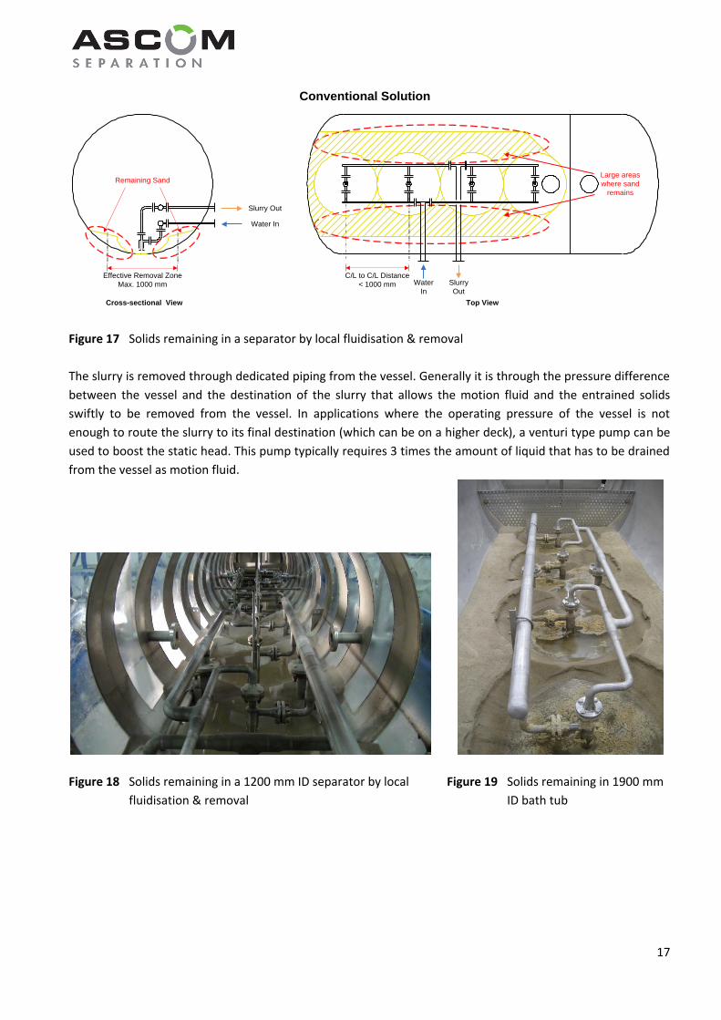
Figure 17 Solids remaining in a separator by local fluidisation & removal
The slurry is removed through dedicated piping from the vessel. Generally it is through the pressure difference
between the vessel and the destination of the slurry that allows the motion fluid and the entrained solids
swiftly to be removed from the vessel. In applications where the operating pressure of the vessel is not
enough to route the slurry to its final destination (which can be on a higher deck), a venturi type pump can be
used to boost the static head. This pump typically requires 3 times the amount of liquid that has to be drained
from the vessel as motion fluid.
Figure 18 Solids remaining in a 1200 mm ID separator by local Figure 19 Solids remaining in 1900 mm
fluidisation & removal ID bath tub
Effective Removal Zone
Max. 1000 mm
Remaining Sand
C/L to C/L Distance
< 1000 mm
Conventional Solution
Large areas
where sand
remains
Water In
Slurry Out
Top ViewCross-sectional View
Water
In
Slurry
Out
18
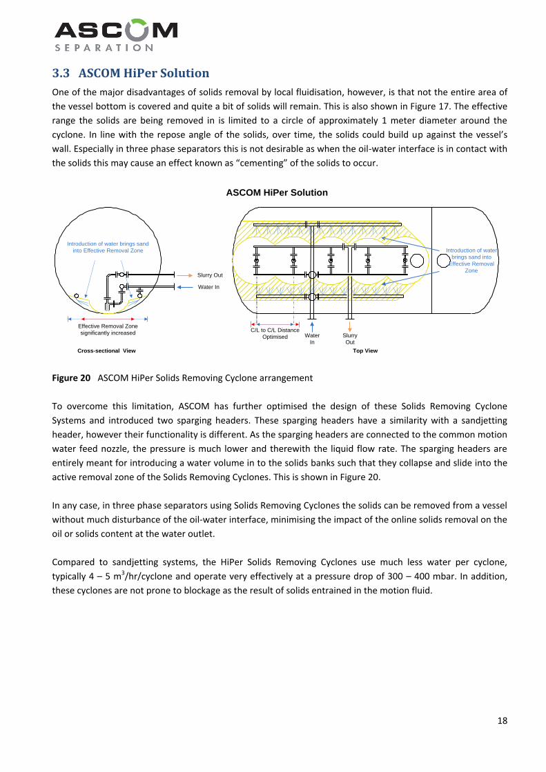
3.3 ASCOM HiPer Solution
One of the major disadvantages of solids removal by local fluidisation, however, is that not the entire area of
the vessel bottom is covered and quite a bit of solids will remain. This is also shown in Figure 17. The effective
range the solids are being removed in is limited to a circle of approximately 1 meter diameter around the
cyclone. In line with the repose angle of the solids, over time, the solids could build up against the vessel’s
wall. Especially in three phase separators this is not desirable as when the oil-water interface is in contact with
the solids this may cause an effect known as “cementing” of the solids to occur.
Figure 20 ASCOM HiPer Solids Removing Cyclone arrangement
To overcome this limitation, ASCOM has further optimised the design of these Solids Removing Cyclone
Systems and introduced two sparging headers. These sparging headers have a similarity with a sandjetting
header, however their functionality is different. As the sparging headers are connected to the common motion
water feed nozzle, the pressure is much lower and therewith the liquid flow rate. The sparging headers are
entirely meant for introducing a water volume in to the solids banks such that they collapse and slide into the
active removal zone of the Solids Removing Cyclones. This is shown in Figure 20.
In any case, in three phase separators using Solids Removing Cyclones the solids can be removed from a vessel
without much disturbance of the oil-water interface, minimising the impact of the online solids removal on the
oil or solids content at the water outlet.
Compared to sandjetting systems, the HiPer Solids Removing Cyclones use much less water per cyclone,
typically 4 – 5 m3/hr/cyclone and operate very effectively at a pressure drop of 300 – 400 mbar. In addition,
these cyclones are not prone to blockage as the result of solids entrained in the motion fluid.
Effective Removal Zone
significantly increased
Introduction of water brings sand
into Effective Removal Zone
ASCOM HiPer Solution
Water In
Slurry Out
C/L to C/L Distance
Optimised
Top View
Water
In
Slurry
Out
Introduction of water
brings sand into
Effective Removal
Zone
Cross-sectional View

19
4 Cyclone-based Removal
4.1 Introduction
Various cyclone-based technologies, both conventional and advanced, have been developed by ASCOM to
remove solids/sludge from well streams, multi phase and single phase process streams. In Chapter 2 various
locations were identified where solids/sludge removal can take place. Since each of these locations represent
different conditions, limitations as well as advantages, for more or less each of these locations a separate type
of desanding technology can be identified. The types identified in Chapter 2 are:
1. Multi phase desander (Conventional Type)
2. Multi phase desander (Advanced Type)
3. Single phase desander (Advanced Type, d > 50 micron)
4. Single phase desander (Conventional Type, d < 50 micron)
5. Single phase desander (Conventional Type, high load)
6. Single phase desander (Advanced Type, high load)
Each of these desanding technologies will be discussed hereinafter.
4.2 Desander Types
The Type 1 Multi Phase Desander is essentially a conventional tangential cyclone. This desander is specifically
suitable for severe service, such as can be found at well heads. The reason for this being is that the openings
are sufficiently large for blockage not to occur, even in situations where sand slugs may occur. The pressure
drop over tangential cyclones typically is in the order of magnitude of between 3 and 10 bar, subject to the
actual process conditions. In high pressure fields where the arrival pressure is reduced over a choke valve,
sufficient pressure will be available for this type of desanding cyclone.
Figure 21 4” Tangential Cyclone
4.2.1 Type 1 – Multi Phase Desander (Conventional)
20
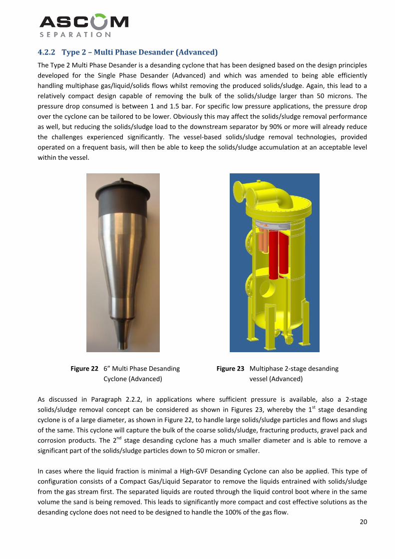
The Type 2 Multi Phase Desander is a desanding cyclone that has been designed based on the design principles
developed for the Single Phase Desander (Advanced) and which was amended to being able efficiently
handling multiphase gas/liquid/solids flows whilst removing the produced solids/sludge. Again, this lead to a
relatively compact design capable of removing the bulk of the solids/sludge larger than 50 microns. The
pressure drop consumed is between 1 and 1.5 bar. For specific low pressure applications, the pressure drop
over the cyclone can be tailored to be lower. Obviously this may affect the solids/sludge removal performance
as well, but reducing the solids/sludge load to the downstream separator by 90% or more will already reduce
the challenges experienced significantly. The vessel-based solids/sludge removal technologies, provided
operated on a frequent basis, will then be able to keep the solids/sludge accumulation at an acceptable level
within the vessel.
Figure 22 6” Multi Phase Desanding Figure 23 Multiphase 2-stage desanding
Cyclone (Advanced) vessel (Advanced)
As discussed in Paragraph 2.2.2, in applications where sufficient pressure is available, also a 2-stage
solids/sludge removal concept can be considered as shown in Figures 23, whereby the 1st stage desanding
cyclone is of a large diameter, as shown in Figure 22, to handle large solids/sludge particles and flows and slugs
of the same. This cyclone will capture the bulk of the coarse solids/sludge, fracturing products, gravel pack and
corrosion products. The 2nd stage desanding cyclone has a much smaller diameter and is able to remove a
significant part of the solids/sludge particles down to 50 micron or smaller.
In cases where the liquid fraction is minimal a High-GVF Desanding Cyclone can also be applied. This type of
configuration consists of a Compact Gas/Liquid Separator to remove the liquids entrained with solids/sludge
from the gas stream first. The separated liquids are routed through the liquid control boot where in the same
volume the sand is being removed. This leads to significantly more compact and cost effective solutions as the
desanding cyclone does not need to be designed to handle the 100% of the gas flow.
4.2.2 Type 2 – Multi Phase Desander (Advanced)

21
The Type 3 Single Phase Desander (Advanced) is a desanding cyclone that has been designed to perfection to
efficiently handling single phase liquid/solids flows whilst removing the produced solids/sludge. This has lead
to a very compact/inline design that removes the bulk of the solids/sludge larger than 50 microns at a pressure
drop between 1 and 1.5 bars. The qualification model is shown in Figure 24.
Figure 24 4” Single Phase Desander (Advanced)
Subject to the specific process conditions, turndown requirements and separation/cut-size requirement, the
desanding cyclones can be designed in a single cyclone configuration or in a bundle.
Solids/sludge accumulator
In any case, from the separation chamber, the separated solids/sludge is drained under gravity into a liquid
filled solids/sludge accumulator. This accumulator can be designed in the same housing or can be an external
hold-up volume/vessel that can be isolated from the process. In the first case where the accumulator is
integrated in the desanding cyclone’s housing, solids/sludge removal is to be done online by using ASCOM’s
HiPer Sand Removing Cyclones or, if the pressure availability allows a sandjetting system. In the latter case, the
solids/sludge accumulator can be isolated and de-pressurised such that the accumulated solids/sludge can
either be removed manually or drained into a big bag. As also will be discussed in Chapter 5, this is more labor
intensive.
4.2.3 Type 3 – Single Phase Desander (Advanced, d>50 micron)
22
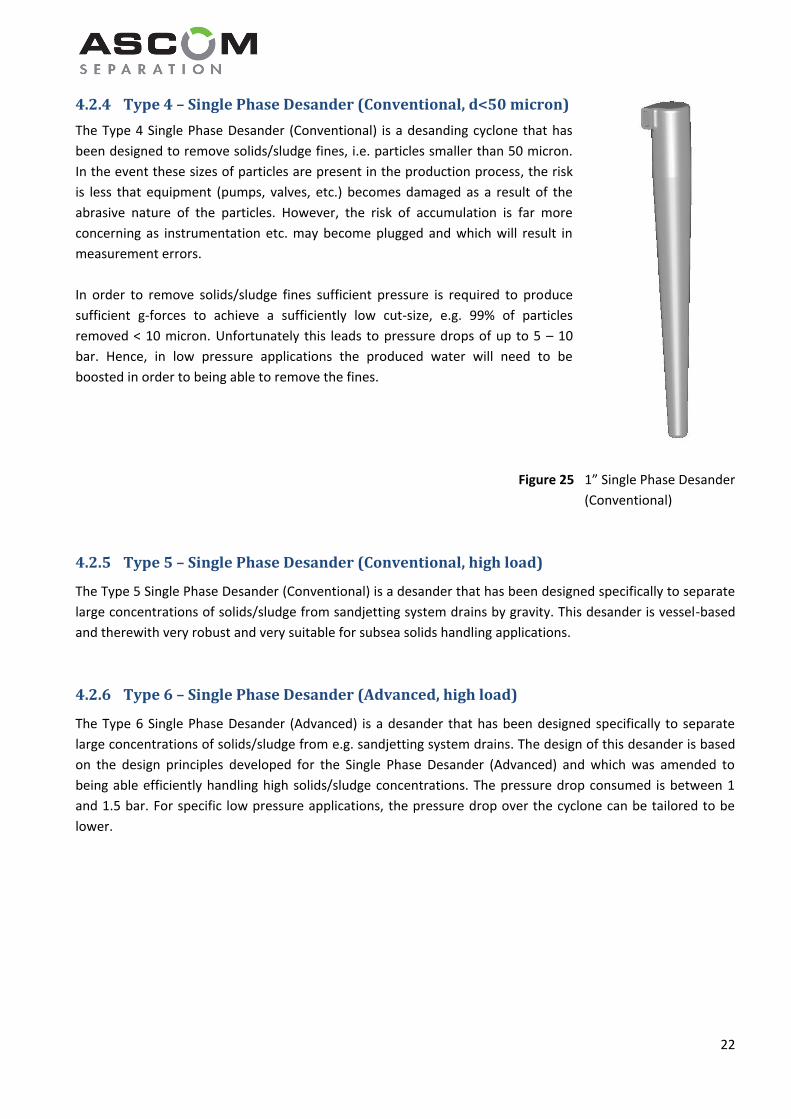
The Type 4 Single Phase Desander (Conventional) is a desanding cyclone that has
been designed to remove solids/sludge fines, i.e. particles smaller than 50 micron.
In the event these sizes of particles are present in the production process, the risk
is less that equipment (pumps, valves, etc.) becomes damaged as a result of the
abrasive nature of the particles. However, the risk of accumulation is far more
concerning as instrumentation etc. may become plugged and which will result in
measurement errors.
In order to remove solids/sludge fines sufficient pressure is required to produce
sufficient g-forces to achieve a sufficiently low cut-size, e.g. 99% of particles
removed < 10 micron. Unfortunately this leads to pressure drops of up to 5 – 10
bar. Hence, in low pressure applications the produced water will need to be
boosted in order to being able to remove the fines.
Figure 25 1” Single Phase Desander
(Conventional)
The Type 5 Single Phase Desander (Conventional) is a desander that has been designed specifically to separate
large concentrations of solids/sludge from sandjetting system drains by gravity. This desander is vessel-based
and therewith very robust and very suitable for subsea solids handling applications.
The Type 6 Single Phase Desander (Advanced) is a desander that has been designed specifically to separate
large concentrations of solids/sludge from e.g. sandjetting system drains. The design of this desander is based
on the design principles developed for the Single Phase Desander (Advanced) and which was amended to
being able efficiently handling high solids/sludge concentrations. The pressure drop consumed is between 1
and 1.5 bar. For specific low pressure applications, the pressure drop over the cyclone can be tailored to be
lower.
4.2.4 Type 4 – Single Phase Desander (Conventional, d<50 micron)
4.2.5 Type 5 – Single Phase Desander (Conventional, high load)
4.2.6 Type 6 – Single Phase Desander (Advanced, high load)

23
5 Handling
5.1 Introduction
Solids/sludge handling essentially comprises of taking the solids/sludge from the location where they are being
accumulated to the location where they are being cleaned and intrinsically removed from the process. In order
to remove the solids/sludge from an accumulator, three methods can be applied:
1) Manual removal
2) Drainage into big bag
3) Online removal
In particular the technologies available for the third method require clean (produced) water at certain
elevated pressures. This may not always be available at (remote) offshore well head platforms, minimum
production facilities or facilities where only 2-phase Gas/Liquid separation is performed. This means that
solids/sludge handling and removal is very likely restricted to Method 1 and 2. For onshore facilities this can be
overcome relatively easy by a mobile water buffer and/or small storage facility.
To remove solids/sludge manually from an accumulator has five distinct disadvantages:
1. It requires vessel entry and therewith an isolation of the vessel
2. It costs extra operational work during isolation work of the vessel
3. It is labor intensive
4. It may not be possible if the size of the accumulator is too small
5. It may not be possible if the big bag can’t be brought easily to the lay down area of the crane
5.1.2 Drainage into big bag
To drain solids/sludge manually from an accumulator has four distinct disadvantages:
1. It requires an isolation of the vessel
2. It costs extra operational work during isolation work of the vessel
3. It is moderately labor intensive
4. It may not be possible if the big bag can’t be brought easily to the lay down area of the crane
In order to aid the drainage of the solids/sludge into the big bag, a small circular sandjetting system should be
installed in the bottom of the accumulator that can be operated manually to flush and fluidise the
solids/sludge during short internals. Such sandjetting system is shown in Figure 26.
Figure 26 Sandjetting system in vertical accumulator
5.1.1 Manual removal

24
5.1.3 Online removal
For the purpose of online solids/sludge removal from a solids/sludge accumulator two technologies exist:
1) Sandjetting system
2) Solids removing cyclones
Sandjetting system
The operating principle of the sandjetting system as has been discussed in Paragraph 3.2.2 for horizontal
vessels is identical to the operating principle applicable to the solids/slurry accumulators. Only the size is
significantly smaller and therewith the water flow requirement. Provided the operating pressure of the
accumulator is sufficiently high and the distance not too far, the solids/sludge can be drained directly to the
location where they are being cleaned without further boosting.
Solids removing cyclones
Specifically for the case where the operating pressure of the solids/sludge accumulator is insufficient and/or
the slurry needs to be transported over a long distance, ASCOM has developed sand removing cyclones. The
operating principle as has been discussed in Paragraph 3.2.3 for horizontal vessels is identical to the operating
principle applicable to the sand removing cyclones installed in solids/sludge accumulators. As the active
removal zone of the sand removing cyclones is approximately 1000 mm, only one unit would be required in
accumulator vessels of up to 1200 mm in diameter. For solids/sludge accumulators this is already quite a
substantial size, but in the event the accumulator for whatever reason is larger in diameter more sand
removing cyclones can and will be considered. This is also shown in Figure 27.
Figure 27 Solids removing cyclones installed in Solids/Sludge Accumulator
Solids removing cyclones are extremely robust as the openings are very large and therewith they are certainly
not prone to blockage in any way. Since the point of removal is exactly there where the solids/sludge is being
fluidised, the feed water clears the way for the solids/sludge removal. The removal can continue until
everything within reach has been fluidised and removed from the accumulator.

25
In order to boost the degree of fluidisation, and therewith removal, a circular sandjetting system could be
installed to essentially break the solids build-up in the vessel by introducing high velocity water jets. Especially
when the accumulator is emptied irregularly and at long intervals, a process so-called ‘cementing’ may take
place whereby the accumulated solids solidify as one big agglomerated lump. Such lumps obviously will be
difficult to remove by fluidisation and in the event it continues to hinder the available accumulation time,
eventually, it may need to be considered removing the lump manually.
The required water flow of 5 m3/hr per solids removing cyclone installed is needed at an inlet pressure of at
least 0.5 bar above the Solids/Sludge Accumulator’s operating pressure. The pressure difference between the
accumulator and the location where solids/sludge is being cleaned, needs to be sufficient in order to overcome
any static heads, pressure losses over control valves & instrumentation and the same over the length of the
piping.
In the event the pressure difference is insufficient, the pressure of the slurry can be boosted by means of a jet
pump. This jet pump is does not contain rotating parts and therewith is considered static equipment. The jet
pump is being fed by a flow rate of produced water of approximately 3 times the flow rate that needs to be
boosted in pressure. The typical source for this produced water is the Produced Water Degassing Drum or the
Floatation Unit. Either the Produced Water Pump or the Sandjetting Pump will deliver the produced water to
the jet pump at an elevated pressure, as needed to boost the pressure to the desired level.
The exact layout of the solids/sludge handling system and its integration thereof in the process facility
depends very much on the exact process layout, its available source(s) of produced water, respective flow
rates and the various operating pressures. For each facility this needs to be carefully reviewed.

26
Sand Cleaning Package & Bagging Station
FIC
Sample
Sand Accumulators
(5 m3/hr)
Separators
Big Bag
Closed Drain
Fines
Separation
7 – 17 bara
FIC
Sample
1.2 bara
FIC
FI
Separators
Sample
Produced Water Degassing Drum
(Compact) Floatation Unit
Overboard
Sample
6 Cleaning
Solids/sludge accumulation locations need to be emptied from time-to-time. This can be done by routing 5
m3/hr/cyclone of produced water to the Solids Removing Cyclones in the Solids/Sludge Accumulation Vessels
at typically 0.5 bar on top of the vessel’s operating pressure. In situations where the operating pressure is too
low, a static jet pump can be used, using produced water at a higher pressure, to remove the slurry from the
respective vessel and transport it to the Solids Cleaning Package.
The main in-flow to the Solids/Sludge Cleaning Package is a discontinued slurry flow from various locations in
the upstream or downstream production processes where solids or solids bound in a sludge are removed by
means of desanding cyclones or can settle in vessels as the result of gravity. It is distinguished between
removing solids/sludge from a Solids/Sludge Accumulators and removing solids/sludge from separators. This is
merely done because of the slurry/water volumes involved. The proposed Solids Cleaning Package & Bagging
Station is depicted in Figure 28.
In the event solids fines are present (d < 50 micron), a small hold-up volume (1.75 m3) is included to serve as a
buffer for motion water to be used around the Solids Cleaning Package. Where otherwise a Produced Water
Degassing Drum or (Compact) Floating Unit would be used as the (preferred) produced water source, in this
specific case this is not done to avoid feeding the solids fines present back into the production system.
In order to limit the pressure class to which the Solids Cleaning Package has to be designed for, it is
recommended to limit the design pressure to 17 bara, and hence the pressure has to be dropped when the
slurry is coming from a Solids/Sludge Accumulator or separator operating at a higher pressure.
Figure 28 Solids Cleaning Package & Bagging Station

27
Solids removal from Solids/Sludge Accumulators
Initially the Solids/Sludge Cleaning Vessel will be empty and in a batch-wise operation it then will receive slurry
of solids from the one of the upstream Solids/Sludge Accumulators. In each of the cases the water flow rate
required is only 5 m3/hr for 15 minutes plus an additional 5 minutes for flushing purposes. This brings the total
volume of produced water being fed to the Solids/Sludge Cleaning Package to 1.75 m3. In order to
accommodate this volume in its entirety a vessel is needed of 42” OD and 2000 mm Seam/Seam distance. The
motion water that is received from the Solids/Sludge Accumulators will contain small quantities of oil which
also partially will be released from the solids itself. It is therefore recommended to return the motion water
that has accumulated in the Solids/Sludge Cleaning Vessel back to one of the separators or Closed Drain Drum
for polishing and using clean motion water from the Produced Water Buffer (fed from a Produced Water
Degassing Drum or (Compact) Floatation Unit) for the solids and/or sludge cleaning operation.
Once the oily motion water has been removed from the Solids/Sludge Cleaning Package and the Solids/Sludge
Cleaning Vessel has been filled with clean water from the Produced Water Buffer and the Produced Water
Buffer having been re-filled, the Solids/Sludge Cleaning Package is to be isolated and the pressure in the
Solids/Sludge Cleaning Vessel raised to 9 barg. Subsequently a produced water flow of 5 m3/hr at a pressure of
9.5 barg is fed to the HiPer Solids Removing Cyclone inside the Solids/Sludge Cleaning Vessel and 15 m3/hr is
fed to the jet-pump at a pressure of 17 barg that is connected to the slurry discharge line coming from the
same HiPer Solids Removing Cyclone.
The diluted slurry coming from the jet-pump is then fed to a Desanding Cyclone on top of the Solids/Sludge
Cleaning Vessel where shear is introduced in a concentrated manner to remove oil residual on the solids
particles. The solids will settle back into the Solids/Sludge Cleaning Vessel under gravity. The motion water
flow of in total 20 m3/hr is routed back to the Produced Water Buffer. In the event solids fines are present, the
motion water can be routed via a small 0.5” – 1” desanding cyclone bundle to remove the solids fines that may
have become entrained in the motion water. The solids fines are collected in the desander housing and
flushed into Big Bags from time-to-time to intrinsically remove the solids fines from the system.
The motion water will need to be fed back one of the separators or Closed Drain Drum from time to time and
replenished with clean produced water from a Produced Water Degassing Vessel or (Compact) Floatation Unit.
This operation is continued until the solids and motion water contain an acceptable level of oil to allow
discharge. Discharge of cleaned solids can be done to sea provided the governmental authorities allow doing
the same or otherwise they have to be collected in Big Bags to allowing transport to shore or to a designated
location onshore where proper waste treatment can be managed and executed.
Solids/Sludge removal from separators
In principle the solids/sludge removal and solids cleaning follows in general lines the description above. The
major difference lies in the volume of motion water required to transport the solids/sludge from separators.
Subject to the size of the separator, a produced water flow rate of 20 – 30 m3/hr to operate the HiPer Solids
Removing Cyclones for a duration of approximately 15+5 minutes per section. The total volume of produced
water used is then 10 m3. Since the Solids/Sludge Cleaning Vessel is only designed to hold 1.75 m3, 8.25 m3
over this 20 minute time span will need to be routed back to one of the separators. Again, if fines are present,
the produced water is routed via a small 0.5” – 1” desanding cyclone bundle.
28
Routing the oily water from the Solids/Sludge Cleaning Package back to a separator or Closed Drain Drum will
allow the oil entrained to become separated when introduced to the vessel in the upstream part close to the
Normal Interface Level.