san luis low point improvement project environmental
TRANSCRIPT

San Luis Low Point Improvement Project Environmental Impact Statement / Environmental Impact Report Appendix A2: Project Description

This page left blank intentionally.
Appendix A2 Project Description
A2-1 DRAFT – July 2019
Appendix A2 Project Description
This section summarizes the alternatives development process for the San Luis Low Point Improvement Project (SLLPIP) and describes the alternatives analyzed in this Environmental Impact Statement/Environmental Impact Report (EIS/EIR).
A2.1 Project Alternatives
The following sections describe the alternatives that are evaluated in this EIS/EIR, including the No Action/No Project Alternative and three action alternatives.
A2.1.1 Alternative 1 - No Action/No Project Alternative
A2.1.1.1 NEPA/CEQA Both National Environmental Policy Act (NEPA) and California Environmental Quality Act (CEQA) require the evaluation of a No Action or No Project Alternative, which presents the reasonably foreseeable future conditions in the absence of the proposed project. The purpose of the No Action or No Project Alternative is to allow decision makers to compare the impacts of approving the project to the impacts of not approving the project. Under NEPA, the No Action Alternative also serves as the baseline to which action alternatives are compared to determine potential impacts. This differs from CEQA, where existing conditions serve as the baseline to determine potential impacts of the alternatives. The No Action/No Project Alternative may differ from the Affected Environment/Existing Conditions if there are actions that could occur in the project area in the future, that 1) currently do not exist and 2) do not rely on approval or implementation of the proposed project. However, because substantive changes in the area of analysis are not expected, the No Action Alternative would be the same as existing conditions/No Project Alternative. The No Action/No Project Alternative reflects, for most resources evaluated in this EIS/EIR, existing and expected future conditions in the project area if no action is taken.
A2.1.1.2 San Luis Reservoir Operations The No Action/No Project Alternative would leave the current operations at San Luis Reservoir unchanged. Santa Clara Valley Water District (SCVWD) would

San Luis Low Point Improvement Project Draft Environmental Impact Statement/Environmental Impact Report
A2-2 DRAFT – July 2019
continue annual operations planning to anticipate curtailment of Central Valley Project (CVP) supply, and would manage its uses and sources of imported and local water supplies.
SCVWD seeks a stable supply of CVP surface water as a part of its larger water supply portfolio that includes imported surface water supplies from the CVP and State Water Project (SWP), local groundwater, and local surface water supplies. Low point supply interruptions reduce the reliability of SCVWD’s CVP supply, which could jeopardize the short and long term reliability of other supplies intended for other uses. For instance, groundwater normally reserved for drought or emergency use may be relied upon during a low point event. A low point supply interruption—and even the threat of an interruption—can result in the immediate reduction of the amount of treated water available for delivery by SCVWD’s customers, because it requires the re-operation of SCVWD’s surface and groundwater systems and requires the use of alternative water supplies that would otherwise be dedicated to other uses. The effects resulting from delivery reductions and/or curtailments due to a low point would continue to pose a significant threat to the customer’s short and long term water supply reliability.
Under this alternative, water supply modeling results have predicted that there would be 17 years (out of the 82 modeled years)1 where the San Luis Reservoir would be drawn below 300 thousand acre-feet (TAF) of storage, i.e. low point years.
A2.1.1.3 Pacheco Reservoir Operations The No Action/No Project Alternative would leave the current operations at Pacheco Reservoir unchanged. North Fork Dam is currently under restricted-operation criteria through an April 5, 2017 order of the California Department of Water Resources (DWR) Division of Safety of Dams (DSOD) due to existing spillway deficiencies. The Pacheco Pass Water District (PPWD) is coordinating with Federal Emergency Management Agency (FEMA) and DSOD on short-term and long-term repairs. The DSOD has stated that if satisfactory progress is not made to address spillway deficiencies, additional remedies would be invoked, inclusive of revocation of the PPWD’s Certificate of Approval to store water. If such certification is revoked, the lake would be drained and the Dam’s outlet structures would be left open, a step that would reduce, among other things, existing fisheries habitat. For the purpose of this EIS/EIR, in order to eliminate the risk of overestimating benefits, it is assumed that the existing reservoir is operated at full operational capacity and consistent with recommendations in the 2014 Report on Comprehensive Strategy and Instructions for Operation of Pacheco Reservoir (i.e., optimized operations for steelhead habitat).
1 Appendix B presents in detail the assumptions and methods used by the CalSim II model to estimate effects from
the No Action/No Project and action alternatives

Appendix A2 Project Description
A2-3 DRAFT – July 2019
A2.1.2 Alternative 2 - Lower San Felipe Intake Alternative The Lower San Felipe Intake Alternative includes construction of a new, lower San Felipe Intake to allow reservoir drawdown to its minimum operating level without algae reaching the San Felipe Intake. Moving the San Felipe Intake to an elevation equal to that of the Gianelli Intake would allow operation of San Luis Reservoir below the 300 TAF level without creating the potential for a water supply interruption to SCVWD.
As part of this alternative, a new intake (see Figure A2-1 for a schematic) would be constructed and connected to the existing San Felipe Division Intake via approximately 20,000 feet of new pipeline or tunnel. The top of the Lower San Felipe Intake is currently at elevation 334 feet and the bottom of the intake is at 313 feet. Algae-laden water can reach the intake when reservoir levels reach approximately 369 feet (approximately 300 TAF in storage). Because the Gianelli Intake Facility is at elevation 296 feet (approximately 30 feet lower than the minimum operating pool), algae-laden water does not typically reach the Gianelli Intake. The new intake in this alternative would be at elevation 296 feet, the same elevation as the Gianelli Intake. The lower intake facility would allow the San Felipe Division to receive water from the lower reservoir levels that do not contain high concentrations of algae. A hypolimnetic aeration facility would also be constructed to increase dissolved oxygen levels in lower reservoir levels to prevent taste and odor issues.
Figure A2-1. Lower San Felipe Intake Alternative

San Luis Low Point Improvement Project Draft Environmental Impact Statement/Environmental Impact Report
A2-4 DRAFT – July 2019
A2.1.2.1 Project Facilities The facilities for the Lower San Felipe Intake Alternative include:
• New intake structure • Extended intake conveyance, either a tunnel or underwater pipeline • Connection to existing intake • Aeration system • Site access improvements • Improved site utilities
Figure A2-2 shows the locations of existing and proposed facilities at San Luis Reservoir under this alternative. Table A2-1 summarizes key features of the project facilities. Modifications to the existing Pacheco Pumping plant are not expected.

Appendix A2 Project Description
A2-5 DRAFT – July 2019
Figure A2-2. Pipeline and Tunnel Alignment for the Lower San Felipe Intake Alternative

San Luis Low Point Improvement Project Draft Environmental Impact Statement/Environmental Impact Report
A2-6 DRAFT – July 2019
Table A2-1. Lower San Felipe Intake Alternative – Key Design and Project Facilities Information
Parameter Specification1 System Information Conveyance Capacity 490 cfs Pacheco Pump Station Static Lift 80 to 310 feet 2,3 San Luis Reservoir Minimum Operating Elevation
326 feet (79 TAF minimum pool elevation)
Connection to Existing Intake Tunnel option New vertical shaft On Gate Shaft Island Elevation 250 feet 3 Diameter 35 to 40 feet Pipeline Option Connection to Existing Intake At existing lower intake at invert 313 feet Intake Extension (Pipeline or Tunnel Option) Inner Diameter 13 feet Length 20,000 feet Head Loss 6 feet New Intake Structure Elevation (top of structure) 296 feet 3 Other Facilities Hypolimnetic Aeration 1 cfs = cubic feet per second; TAF = thousand acre-feet 2 Unchanged from existing conditions 3 feet above mean sea level
A2.1.2.1.1 New Intake Structure The new intake structure would allow water to be drawn from an elevation of 296 feet to continue deliveries to the San Felipe Division during a low point event. The intake structure would consist of a vertical steel riser pipe, with a trash rack at the intake opening similar to the two existing intake structures. The conduit invert elevation at the new intake would be approximately 250 feet for the tunnel option and 280 feet for the pipeline option.
The existing upper and lower intakes would still be functional after the new conduit and lower intake are operational; however, valves or other means of isolation would be installed such that the existing intake structures could be isolated from service prior to low point events.
A2.1.2.1.2 Intake Extension Lowering the San Felipe Intake would require an extension of the intake for the Pacheco Pumping Plant because the reservoir is higher on the west side than at the site of the Gianelli Intake. The conveyance structure from the new intake to the existing intake would be either a submerged pipeline along the bottom of the reservoir or a tunnel beneath the bottom of the reservoir.

Appendix A2 Project Description
A2-7 DRAFT – July 2019
Tunnel Option A tunnel would be constructed beneath the reservoir floor to convey water from the new intake to the existing intake. The tunnel option includes a new vertical shaft on Gate Shaft Island to tie into the existing intake and serve as a beginning point to launch the tunnel boring equipment. The tunnel would be about 20,000 feet long, 15 feet in diameter, and the liner would have an inner diameter of 13 feet. Figure A2-3 shows the tunnel profile.
Figure A2-3. Lower San Felipe Intake Alternative Tunnel Profile
Pipeline Option For the pipeline option, a new 13 foot diameter reinforced concrete cylinder pipe would be laid along the bottom of San Luis Reservoir. The pipeline would be about 20,000 feet. The pipe would have a constant slope upward from the new intake and tie into the invert of the existing lower intake at elevation 313 feet. An existing intake channel is graded along the bottom of the reservoir. To reduce the amount of dredging required, the pipeline’s alignment would match the alignment of the existing intake channel. Figure A2-4 shows the pipeline profile.

San Luis Low Point Improvement Project Draft Environmental Impact Statement/Environmental Impact Report
A2-8 DRAFT – July 2019
Figure A2-4. Lower San Felipe Intake Alternative Pipeline Profile
A2.1.2.1.3 Connection to Existing Intake The new intake pipeline or tunnel would connect to the existing intake, either at Gate Shaft Island for the tunnel option, or at the existing lower intake for the pipeline option. Gate Shaft Island is a 4 acre area approximately 2,050 feet from the existing lower intake. The San Felipe Division would likely experience a service interruption during the tie-in work.
Tunnel The tunnel option would require a new vertical shaft on Gate Shaft Island for the tunneling equipment; this new shaft would connect to the existing intake shaft by a short connection structure constructed between the two shafts. The wall of the existing shaft would need to be penetrated in order to complete the connection. The new vertical shaft on the island would be 35-40 feet in diameter and approximately 330 feet deep.
Pipeline The pipeline option would require a temporary coffer dam-style structure be constructed to allow for connection of the new pipeline to the existing intake. The coffer dam structure would be approximately 35 feet in diameter.
A2.1.2.1.4 Hypolimnetic Aeration System During periods of low water levels and warm weather, water within the reservoir can stratify, resulting in a hypolimnion layer at the elevation of the proposed new lower intake. The reduced level of dissolved oxygen in the

Appendix A2 Project Description
A2-9 DRAFT – July 2019
hypolimnion could potentially lead to taste and odor issues in the water drawn from this layer. A new aeration system would be constructed to oxygenate the reservoir and prevent stratification. The aeration system would consist of a new facility near Romero Visitor Center (shown on Figure A2-2). A liquid oxygen tank and vaporizers or a compressed air system are being considered for the aeration facility. Either system would be placed in a structure with an approximate footprint of 1,200 square feet. A 3 inch air supply line would connect to approximately 6,000 feet of submerged high-density polyethylene air diffuser piping within the reservoir.
A2.1.2.1.5 Site Access Improvements Improved road access from State Route (SR) 152 to the Dinosaur Point and Basalt staging areas may be needed to accommodate the high volume of trucks and other heavy equipment anticipated during construction. Road reinforcement would be necessary at the intersections of SR 152 and the access roads to Dinosaur Point and Basalt use areas. Also, temporary paved roads would be constructed for truck transportation of materials between stockpiling areas and the launching area at the reservoir. Existing recreation boat launching ramps may be used for construction activities; however, if the ramps are unsuitable, a temporary ramp would be constructed for moving equipment and materials into the reservoir.
A2.1.2.1.6 Site Utilities Temporary power facilities would be needed for construction equipment, welding and trailers at the Dinosaur Point boat launch area. Power would be provided by portable generators.
A2.1.2.2 Construction Methods A2.1.2.2.1 Intake Structure The new intake structure would be constructed on shore in 10 foot segments. The segments would be transported to the permanent intake location on a barge, and then lowered into the reservoir using a crane. Intake segments would be stacked on top of each other to achieve the full intake height, and welded by divers to join and seal the segments.
Tunnel Option For the tunnel option, the intake structure would be approximately 46 feet long and 54 feet tall, spanning from the intake elevation of 296 feet to the bottom of the tunnel at 250 feet.
The material volume generated by excavation via barge mounted dredge for the intake structure under would be approximately 49,000 cubic yards. This material would be transported via barge for disposal at Dinosaur Point.

San Luis Low Point Improvement Project Draft Environmental Impact Statement/Environmental Impact Report
A2-10 DRAFT – July 2019
Pipeline Option The intake structure would be shorter for the underwater pipeline option than the tunnel option since it would only need to span between the intake elevation of 296 feet to the bottom of the reservoir at approximately 280 feet. The final connection to the underwater pipeline would be made by divers.
Dredges would be used to modify the existing intake channel which would serve as a trench for the underwater pipeline. Minimal dredging is expected, since the existing channel is at an approximate elevation of 313 feet. Approximately 9,000 cubic yards of spoils would be generated by the pipeline option. This material would be disposed of by distribution along the bottom of the reservoir.
A2.1.2.2.2 Intake Extension Tunnel Construction Based on the anticipated alluvial and the potential for Pacheco formation soil materials, and the need to tunnel beneath the groundwater level, the tunnel would be constructed using an Earth Pressure Balance Tunnel Boring Machine (TBM). The TBM would be transported to Gate Shaft Island via a barge and lowered into the access shaft with a crane. Material would be excavated at the front of the TBM and a precast concrete lining would be installed behind the cutting head of the TBM. The lining would function as initial support as well as the permanent liner. This method is known as the one-pass system. No intermediate tunnel access shafts would be possible because work would be conducted below the bottom of the reservoir. Therefore, all TBM repairs and cutter replacement procedures would need to be performed from within the tunnel. Dewatering and blasting during construction would not be necessary. Hazardous materials are not expected to be encountered.
The tunnel option would require that the TBM be removed at the proposed lower intake location within the reservoir. This action would be completed in summer months when seasonal storage at San Luis Reservoir is at its lowest. A temporary coffer dam-style structure would be constructed within the reservoir around the new tunnel outlet to allow for removal of the TBM, and aiding in the tunnel connection to the new intake structure. The temporary coffer dam structure would be larger than the new intake structure, and would isolate the new intake while the tunnel connection is made. Alternatively, the TBM could be stripped of any fuels, oils, and salvageable components and abandoned in place, and the intake structure connection could be made by divers.
Pipeline Construction Dredges would be used to modify the existing intake channel which would serve as a trench for the underwater pipeline. Minimal dredging is expected, since the existing channel is at an approximate elevation of 313 feet. Pipe segments of 50 foot lengths would be transported by tug boats from the staging area to a barge, then lowered into the reservoir with a crane. Connection of pipe segments would be made by divers. Pipeline installation would occur in water

Appendix A2 Project Description
A2-11 DRAFT – July 2019
up to 265 feet deep in some areas, which would require professional divers with specialized technical deep dive certifications and deep water equipment. The availability of qualified divers in the project vicinity may be limited. The use of divers could be reduced if construction occurs during a period where the reservoir is low because of a drought cycle. However, construction would not cause any changes to the CVP or SWP operations in the reservoir. To prevent any pipeline shifting or buoyancy issues, it would be anchored with precast concrete saddles. Spacing and sizing would be determined during future design tasks.
A2.1.2.2.3 Access Shaft and Coffer Dams Construction of a new permanent access shaft on Gate Shaft Island would only be necessary for the tunnel option. Construction of temporary coffer dam structures is anticipated for both the tunnel and pipeline options in order to complete intake connections within the reservoir.
Tunnel Option For the tunnel option, a permanent shaft would be assembled at Gate Shaft Island to function as a launch point for the TBM. To control groundwater conditions and improve subsurface working conditions during excavation of the shaft, ground freezing would be utilized during excavation. A temporary coffer dam-style structure would be constructed within the reservoir for removing the TBM, and aiding in the tunnel connection to the new intake structure.
Pipeline Option For the pipeline option, a temporary coffer dam-style structure would be constructed around the existing lower intake structure to allow for connection of the new intake pipeline. Depending on the reservoir water level, either the upper intake or both intakes would need to be isolated. Steel segments would be used to create the coffer dam to isolate the work area around the existing intake structure. The coffer dam would be removed after the tie-in is complete.
A2.1.2.3 Equipment, Materials, Spoils and Safety Equipment in the staging areas would include trailers, equipment to be used, and stockpiled materials. Construction staging and stockpile areas would include:
• Dinosaur Point Use Area for both the tunnel and pipeline options. Dinosaur Point Use Area consists of 10 acres.
• Basalt Use Area for the new intake structure construction. Basalt Use Area consists of 10 acres.
• Area south of Gianelli Pumping Plant off of Gonzaga Road, for the transporting materials to the new intake location. The area proposed for use consists of 5 acres.

San Luis Low Point Improvement Project Draft Environmental Impact Statement/Environmental Impact Report
A2-12 DRAFT – July 2019
The main staging area access route would be SR 152 to Dinosaur Point Road. Most of the traffic to the site would come from the east. Construction related traffic would likely begin 1 to 2 months after Notice to Proceed. Approximately 6 to 12 large deliveries per day could be expected, the transport and disposal of approximately 1,200 cubic yards of material to local landfills, along with the regular commuting of construction personnel.
Aside from areas dedicated to construction staging and transportation, all remaining available space at Dinosaur Point and Basalt use areas would be needed for stockpiling materials and recreational use of these areas would be closed for the full construction duration. Dinosaur Point would be used as a staging area of the full duration of construction. This area would be returned to pre-construction condition after the project is completed. Materials stored include precast pipe or concrete tunnel lining segments, and pipeline concrete cap anchors.
The closest concrete batch plants are located in Los Banos, approximately 30 to 40 minutes driving time from reservoir access locations. Materials from local batch plants would be used for road improvement work and construction of the new intake structure. It is assumed that an on-site concrete batch plant would not be needed.
Procurement and delivery of the barges and cranes required is expected to be some of the more difficult aspect of construction mobilization.
Since San Luis Reservoir is a drinking water source and specialized construction methods would be utilized for installation of the new intake and conduit, the following special safety measures would be implemented during construction within the reservoir:
• Use of food grade oil for equipment lubricants, • Installation of turbidity curtains surrounding existing intakes, if
operational, • Certified professional divers (for the pipeline option).
A2.1.2.3.1 Tunnel Option Equipment used in the reservoir for the tunnel option would include:
• Tunnel boring machine • Barge • 1-2 Boats • Cranes (2 large, 2 small) • 2 Large excavators • 2-3 Chiller plants • Drill rig

Appendix A2 Project Description
A2-13 DRAFT – July 2019
• 1-2 Bulldozers • 1-2 Loaders • Scraper • 2 Dump trucks • 1-2 Water trucks
Between 163,000 and 184,000 cubic yards of excavated material would be generated by the tunneling option. This quantity accounts for the expansion of excavated materials, and an increase due to soil conditioners used by a TBM. Excavated materials would be disposed of at Dinosaur Point and used to increase the boat ramp area. The material would be spread over 100-115 acres and would result in a 1 foot increase in grade.
A2.1.2.3.2 Pipeline Option For the pipeline option, anticipated equipment would include:
• Barge • 3-4 Boats • Dredging barge or boat • 2 Small cranes • Bulldozer • Loader • Dump truck • Water truck
A2.1.2.4 Construction Schedule Figure A2-5 shows the project schedule for the tunnel and pipeline options. It is assumed for the purpose of this EIS/EIR, that construction would start in 2020. Recreational activities within the reservoir and at the Dinosaur Point and Basalt use areas would be suspended for safety reasons during period of tunnel or pipeline construction. Service would be interrupted temporarily when the new facilities are tied-in to the existing intake and tunnel system.
A2.1.2.4.1 Tunnel Option Schedule Construction is expected to last approximately 47 months. The construction duration is based on 30-50 total anticipated workers on site, 12 of which would be working within the tunnel. Work would be performed 24 hours per day, 7 days a week.

San Luis Low Point Improvement Project Draft Environmental Impact Statement/Environmental Impact Report
A2-14 DRAFT – July 2019
A2.1.2.4.2 Pipeline Option Schedule Construction would last 33 months, and would focus on installing as much of the pipeline as possible during low water periods. Twenty workers are estimated to be on site for construction. Work would be performed for 10 hours per day, from 7:00 a.m. to 5:00 p.m., 5 days a week.
Figure A2-5. Lower Intake Schedule
A2.1.2.5 Operation of the Lower San Felipe Intake Alternative The Lower San Felipe Intake Alternative would allow the San Felipe Division to draw water from San Luis Reservoir at the same elevation as the Gianelli Intake, which serves other CVP South-of-Delta contractors. This new lower intake would allow reservoir drawdown to its minimum operating level without algae reaching the San Felipe Intake.
Installation of the new lower intake structure at elevation 296 feet, and accounting for the same 35 foot deep algae growth layer at the surface of the reservoir, would allow a new low water elevation for the reservoir of 331 feet.

Appendix A2 Project Description
A2-15 DRAFT – July 2019
This elevation also coincides with the maximum potential drawdown elevation currently supported by the pumps at the Pacheco Pumping Plant. The minimum drawdown elevation allowed by the existing vertical pumps and intake shafts (325 feet) plus the anticipated head loss through the new 20,000 foot long intake tunnel or pipeline (anticipated to be approximately 6 feet) also allows a minimum low water elevation of 331 feet.
The Lower Intake Alternative would provide approximately 1,400 acre-feet (AF) of additional south of Delta CVP and SWP Table A supply and on an average annual basis compared to No Action. Figure A2-6 shows how the Lower Intake Alternative addresses SCVWD low point water supply interruptions along with treated water demand shortages in the No Action Alternative. Results show that the Lower Intake Alternative would allow uninterrupted delivery of SCVWD CVP municipal and industrial (M&I) deliveries in all low point years and would be able to fully replace SCVWD’s unmet treated water demand in 10 of the 17 low point years. By allowing the delivery of imported CVP supply during low point periods, SCVWD would need to rely less heavily on locally stored surface and groundwater supplies.
Figure A2-6. Annual Shortages Addressed by the Lower San Felipe Intake Alternative
0
5,000
10,000
15,000
20,000
25,000
30,000
35,000
1922
1925
1928
1931
1934
1937
1940
1943
1946
1949
1952
1955
1958
1961
1964
1967
1970
1973
1976
1979
1982
1985
1988
1991
1994
1997
2000
2003
Acre
-Fee
t
Shortages Addressed by Lower Intake Alternative Non Low Point Year Demand ShortagesLow Point Year Interrupted Supply Low Point Year Demand Shortages

San Luis Low Point Improvement Project Draft Environmental Impact Statement/Environmental Impact Report
A2-16 DRAFT – July 2019
A2.1.3 Alternative 3 - Treatment Alternative The SLLPIP Feasibility Report identifies the Treatment Alternative as the Preliminary Proposed Alternative Plan. The Treatment Alternative would develop new technology retrofits at the SCVWD’s Santa Teresa WTP. This WTP is supplied with water from San Luis Reservoir, which during low point conditions can contain high concentrations of algae.
The Treatment Alternative would develop new treatment technology at the SCVWD WTP to address some of the negative impacts associated with increased algae during low point events. The proposed improvements evaluated under this alternative would include adding a raw water ozonation process to the Santa Teresa WTP. This would result in the following treatment train (new processes are underlined): raw water ozonation, chemical coagulation, conventional clarification, settled water ozonation, granular media filtration with a granular activated carbon (GAC)/sand media configuration, and disinfection.
A2.1.3.1 Project Facilities As noted above the Treatment Alternative would install new treatment technology retrofits at the Santa Teresa WTP to improve the WTP’s ability to treat water from San Luis Reservoir during low point conditions. This section outlines the existing treatment facilities at the WTP and the new facilities that would be developed under this alternative.
The existing Santa Teresa WTP treatment process includes chemical coagulation, conventional clarification, settled water ozonation, granular media filtration, and disinfection.
Chemical coagulation includes the addition of alum, a cationic polymer, and the ability to add chlorine or chloramines as a pre-oxidant. The conventional clarification process includes pump water injection for rapid mixing, 3-stage tapered mixing for flocculation, and rectangular basins for gravity sedimentation. The sedimentation basins utilize chain and flight mechanisms to remove settled solids. Ozonation includes liquid oxygen, ozone generators and 8-cell ozone contactor structures to provide a maximum ozone dose of 2 milligrams per liter (mg/L). Hydrogen peroxide can be dosed at concentrations up to 1.5 mg/L to improve oxidation of taste and odor causing compounds. Filtration includes 12 granular media filters with 48 inches of GAC over 10 inches of sand. The filters operate at loading rates of 6.0 to 7.2 gallons per minute/square foot and are cleaned using both an air and water backwash. Disinfection includes free chlorine contact time and chloramine formation for disinfectant residual.

Appendix A2 Project Description
A2-17 DRAFT – July 2019
Solids handling facilities include washwater recovery basins and sludge drying beds. The recovered washwater is returned to the headworks of the plant. The recovered decant water from the sludge drying beds is returned to the washwater recovery basins, and the dried sludge is disposed of in a landfill.
The Treatment Alternative would add a raw water ozonation process to the treatment train at the Santa Teresa WTP. A site plan of the Santa Teresa WTP with the raw water ozonation process is shown in Figure A2-7. Raw water ozonation is described in further detail in the section below.
A2.1.3.1.1 Raw Water Ozonation In a raw water ozonation process, ozone is added to the raw water entering the treatment plant before the water is treated by any other processes. Ozone oxidizes taste and odor causing compounds and other dissolved organic material released by algae. Ozone also improves clarification and filtration processes when used as a pre-oxidant. Implementation of a raw water ozonation process at the Santa Teresa WTP would require installation of a new ozone contactor, new ozone generation equipment housed in a new building, and new liquid oxygen storage facilities. The proposed location of these facilities are shown in Figure A2-7. New chemical storage and dosing facilities may be required to support the raw water ozonation process.
A2.1.3.2 Construction Methods Construction of the Treatment Alternative retrofits at the SCVWD WTP would be completed in compliance with existing SCVWD design standards.
Replacement of the ozone generation equipment at the Santa Teresa WTP would require a plant shutdown. According to SCVWD staff, the plant can be shut down for up to 4 months. So, this work would need to be completed in a 4-month period. A plant shutdown would also be required for relocation of the existing duct bank. It is estimated that this work can be completed in a 1-month period.
All other structures, equipment, and piping can be installed with the plant in operation. However, tie-in of all new piping, electrical feeders, and instrumentation and control system feeders would need to take place during the 4-month shutdown period described previously. Installation of the new equipment adjacent to existing facilities in operation would need to be closely coordinated with plant operations for safety purposes.

San Luis Low Point Im
provement Project
Draft E
nvironmental Im
pact Statement/Environm
ental Impact R
eport
A2-18 DR
AFT – July 2019
Figure A2-7. Santa Teresa WTP Conceptual Site Plan – Raw Water Ozonation

Appendix A2 Project Description
A2-19 DRAFT – July 2019
A2.1.3.3 Equipment and Staging Equipment in the staging areas would include trailers and equipment to be used. Construction staging areas would be set up during the period of construction. It is anticipated that construction staging areas would be established at the WTP. The staging areas would be located on site and would not encroach on neighboring parcels. Construction equipment would include cranes, excavators, bulldozers, loaders, backhoes, ready mix concrete trucks, concrete pumpers, dump trucks, water trucks, flatbed trucks, and gravel, air compressors, concrete saw cutters, demolition equipment, and portable diesel generators. The Treatment Alternative would also require the transport and disposal of approximately 7,000 cubic yards of material at local landfills.
A2.1.3.4 Treatment Alternative Construction Schedule Construction work would be performed for 10 hours per day from 7:00 a.m. to 5:00 p.m., 5 days a week. The construction, testing and startup of the Treatment Alternative is anticipated to be approximately 3 years. It is assumed for the purpose of this EIS/EIR, that construction would start in 2020.
A2.1.3.5 Operation of the Treatment Alternative The Treatment Alternative would leave current SCVWD operations largely unchanged with the exception of periods with low point conditions in San Luis Reservoir (typically August and September) when SCVWD operators would be able to continue to take delivery of water supply from the reservoir while maintaining WTP performance.
The Treatment Alternative would provide additional water supply to meet SCVWD treated water demands when compared to the No Action Alternative by avoiding low point generated water supply interruptions. The additional water supply provided under the Treatment Alternative would be the same as the Lower Intake Alternative as both alternatives allow SCVWD to receive its full allocation of water stored in San Luis Reservoir. Figure A2-8 shows how the Treatment Alternative addresses SCVWD low point water supply interruptions along with treated water demand shortages in the No Action Alternative. Results show that the Treatment Alternative would allow uninterrupted delivery of SCVWD CVP M&I deliveries in all low point years and fully replace unmet treated water demand in 10 of the 17 low point years. By allowing the delivery of imported CVP supply during these low point periods, SCVWD would need to rely less heavily on locally stored surface and groundwater supplies. By allowing the delivery of imported CVP supply during low point periods, SCVWD would need to rely less heavily on locally stored surface and groundwater supplies.

San Luis Low Point Improvement Project Draft Environmental Impact Statement/Environmental Impact Report
A2-20 DRAFT – July 2019
Figure A2-8. Annual Shortages addressed by the Treatment Alternative
A2.1.4 Alternative 4 - San Luis Reservoir Expansion Alternative The San Luis Reservoir Expansion Alternative would be completed by placing additional fill material on the dam embankment to raise the dam crest to increase storage capacity. The alternative would build upon the dam embankment expansion and foundation modifications to address the seismic concerns that are currently in final design. The seismic modifications to B.F. Sisk Dam currently under Reclamation’s Safety of Dams (SOD) Act, as amended, that the San Luis Reservoir Expansion Alternative would build on are included in this alternative as connected actions as defined under NEPA. The San Luis Reservoir Expansion Alternative would allocate the increased capacity to the CVP only. This expanded capacity would be operated in the same way as the current CVP portion of San Luis Reservoir, with the reservoir used for seasonal storage.
Increasing storage capacity in San Luis Reservoir would potentially increase the yield of the CVP in years that surplus supplies in excess of the reservoir’s existing storage capacity are available. This increased yield could increase SCVWD’s capacity to access their CVP supply prior to the reservoir being drawn below the 300 TAF level and allow the District to avoid the potential for a water supply interruption from low point conditions.
0
5,000
10,000
15,000
20,000
25,000
30,000
35,000
1922
1925
1928
1931
1934
1937
1940
1943
1946
1949
1952
1955
1958
1961
1964
1967
1970
1973
1976
1979
1982
1985
1988
1991
1994
1997
2000
2003
Acre
-Fee
t
Shortages Addressed by Lower Intake Alternative Non Low Point Year Demand ShortagesLow Point Year Interrupted Supply Low Point Year Demand Shortages

Appendix A2 Project Description
A2-21 DRAFT – July 2019
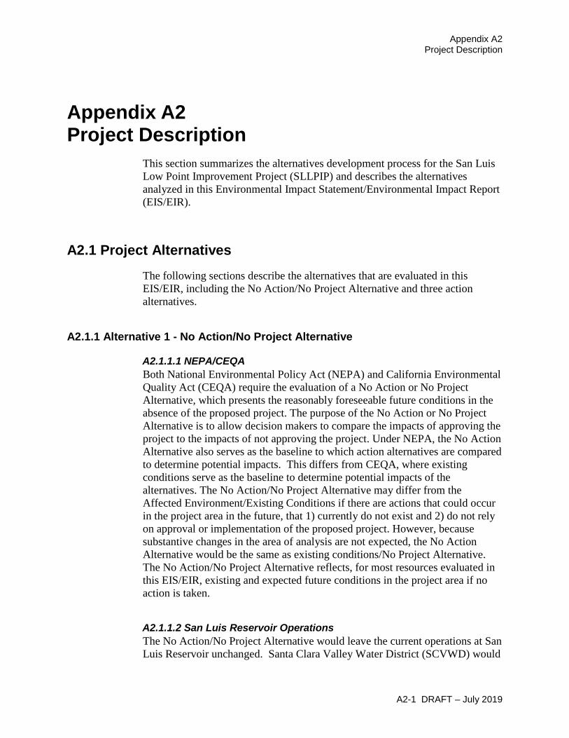
As part of this alternative, the dam crest would be raised by adding additional embankment material (see Figure A2-9 and Figure A2-10), and downstream stability berms and crack filters would be installed. Construction of foundation shear keys at slopewash sections in the abutments and the north valley section (NVS), and a filter around the downstream portion of the existing spillway conduit are also included in this alternative. The existing saddle dike located north of the main embankment would be modified by adding a downstream filter. In addition to these modifications, development of a foundation shear key at the south valley section (SVS) is under consideration as an optional additional feature of this alternative. With increased reservoir surface elevations, modifications would also be made at multiple locations along SR 152 to prevent inundation of the roadway when the enlarged reservoir is filled to capacity, and modifications to the Dinosaur Point Boat Launch and the Goosehead Point Boat Launch would be made to increase the ramps operating elevation by 10 feet. The existing berm developed during construction of the Pacheco Pumping Plant would be reconstruction with a higher crest elevation to protect the plant at high storage levels (see Figure A2-11).
A2.1.4.1 San Luis Expansion Project Facilities As noted above the San Luis Reservoir Expansion Alternative would expand storage in San Luis Reservoir to increase the yield of the CVP and the SWP, by supporting in some years when conditions permit, increases in south of Delta exports. This section outlines the physical modifications that would that would be developed under this alternative.
A2.1.4.1.1 B.F. Sisk Dam B.F. Sisk Dam is a zoned earthfill structure with a maximum structural height of 382 feet, a crest length of 18,600 feet, a crest width of 30 feet, and a crest elevation of 556 feet. The dam embankment was constructed of five materials in seven zones, with the central zone consisting primarily of low-plasticity clays (see Figure A2-10). The downstream face of the dam is covered by a 2-foot-thick cobble blanket, and the upstream face is covered by a 3-foot-thick layer of riprap. Both thickness measurements are normal to the dam slope. A saddle dike, known as the East Dike, is present along the north rim of the reservoir, approximately 1,300 feet from the dam.
The foundation that the dam is built on can be divided into sections: the right abutment, the left abutment, the NVS, and the SVS (See Figures A2-9 and A2-12). The NVS and SVS are the alluvial channels of San Luis Creek and Cottonwood Creek that B.F. Sisk Dam impounds and consist of deposits of sands and gravels with clayey or silty fines. The abutments are primarily founded on bedrock (sandstone, shale, and conglomerate), which is covered by clayey slopewash in some locations. In addition, the East Dike is also partially founded on slopewash.
Studies completed during the Corrective Action Study (CAS) have identified the potential for significant deformation (crest settlement) of the dam in the

San Luis Low Point Improvement Project Draft Environmental Impact Statement/Environmental Impact Report
A2-22 DRAFT – July 2019
sections built on the alluvium and clayey slopewash during a seismic event (Reclamation 2013). The SOD seismic modification will address this deformation potential with the placement of downstream stability berms anchored to bedrock and placement of additional embankment materials on the downstream slope of the dam to increase the crest elevation 10 feet, increasing the distance between the water surface and the dam crest (freeboard) to prevent reservoir overtopping and failure in the event of earthquake-induced deformations (Reclamation 2013).
In addition to dam crest deformation, seismic shaking can cause cracks in the dam embankment susceptible to erosion that can lead to dam failure. Downstream crack filters restrict the migration of soil materials through these cracks mitigating the potential for post seismic cracks to induce internal erosion within the dam embankment. The SOD modification will address this seismic crack induced erosion risk by installing downstream filters along the upper portion of the embankment across the entire length of the dam.
Evaluation of the seismic shaking potential at B.F. Sisk Dam has identified the potential need for additional modification to the foundation soils beneath the SVS berm. The development of a foundation shear key is being evaluated as an optional modification in the San Luis Expansion Project Alternative. A foundation shear key is developed by removing the weak overburden foundation soils found beneath the berm footprint and replacing them with material with a higher shear strength.
The San Luis Reservoir Expansion Alternative would build on the physical SOD modifications currently under final design and raise the dam crest an additional 10 feet to a new crest elevation of 576 feet. This additional 10 feet in embankment height would support a new water surface elevation of 554 feet and an additional 120 TAF in storage capacity. In addition to the new embankment height added by the reservoir enlargement the existing outlet works intake towers, access bridge, and spillway intake would need to be raised by 10 feet.
A2-23 D
RAFT – July 2019
Appendix A2
Project Description
Figure A2-9. Construction and Staging Areas

A2-24 DR
AFT – July 2019 San Luis Low
Point Improvem
ent Project D
raft Environm
ental Impact Statem
ent/Environmental Im
pact Report
Figure A2-10. Typical Cross-Section View and Embankment Materials

Chapter A2 Project Description
A2-25 DRAFT – July 2019
Figure A2-11. Reservoir Expansion Actions along State Route 152 and at Pacheco Pumping Plant

San Luis Low Point Improvement Project Draft Environmental Impact Statement/Environmental Impact Report
A2-26 DRAFT – July 2019
Figure A2-12. Dam Expansion Profiles

Chapter A2 Project Description
A2-27 DRAFT – July 2019
San Luis Reservoir seasonally operates in most years with an approximately 6-month period that CVP and SWP supplies are pumped into the reservoir followed by an approximately 6-month period where the reservoir is drawn down as those stored supplies are delivered to water users. Any work that would reduce the reservoir embankment strength, such as foundation or embankment excavation, would be timed seasonally and would occur during periods of the year when the reservoir is drawn down to lower elevations. As the reservoir is drawn down as a part of regular operations, construction would start after the reservoir is drawn below an elevation sufficient to ensure slope stability during any work that would impact embankment strength. This work would also be scheduled for completion each year prior to the refill of San Luis Reservoir back above safe level to protect embankment stability. Scheduling work during regular periods of drawdown would allow for uninterrupted water supply deliveries. Delays to refill could potentially occur if the construction schedule is delayed, but the division of specific modification actions scheduled to occur in one drawdown season would be structured to minimize this risk. In addition, contract requirements would require use of the second construction shift on this particular component of the overall project in the event that work becomes delayed.
Implementation of the optional SVS shear key action would require limits on the maximum surface elevation in San Luis Reservoir for two fill and drawdown seasons, during the period that the berm foundation would be excavated. This reduction in surface elevation would reduce storage capacity in the reservoir and could limit CVP and SWP deliveries during this construction period. If implemented, the shear key reservoir restriction would consist of a 55-foot reduction in the maximum water surface elevation of San Luis Reservoir from the current elevation of 544 feet to 489 feet. Excavation activities for the shear key would initiate when the reservoir is drawn down to 489 feet as a part of regular reservoir operations and would continue through two refill periods during which the reservoir would not be allowed to refill above that level. Reclamation and SCVWD would also target initiation of the shear key modification if possible, in a year where initial water supply forecasts are projecting dry or critically dry conditions to lessen the magnitude of this reservoir restriction’s impact in at least the first year of its two-year implementation window.
A2.1.4.1.2 Cottonwood Bay/State Route 152 Sections of SR 152 near and at Cottonwood Bay could potentially be impacted by the 10 foot increase in water surface elevation, and would be protected by the development of berms separating the reservoir from the roadway in periods when storage in the enlarged reservoir is full (see Figure A2-10).
A2.1.4.1.3 Pacheco Pumping Plant West Dike The Pacheco Pumping Plant is located on the western side of San Luis Reservoir. The pumping plant is separated from San Luis Reservoir by an approximately 500-foot wide dike east of the pumping plant (see Figure A2-10).
San Luis Low Point Improvement Project Draft Environmental Impact Statement/Environmental Impact Report
A2-28 DRAFT – July 2019
This dike would be replaced with a new dike 20 feet taller than the existing structure to protect the pumping plant from the enlarged reservoir.
A2.1.4.1.4 Dinosaur Point Boat Launch The Dinosaur Point Boat Launch is located on the western side of San Luis Reservoir close to the Pacheco Pumping Plant. The boat ramp and portions of the parking lot at Dinosaur Point would be inundated with the 10-foot increase in surface elevation requiring modifications to the facility to maintain launching functions during periods when the enlarged reservoir is at capacity (see Figure A2-10).
A2.1.4.1.5 Goosehead Point Boat Launch The Goosehead Point Boat Launch is located on the southern side of San Luis Reservoir close to Basalt Hill. The boat ramp and parking lot at Goosehead Point would be inundated with the 10-foot increase in reservoir surface elevation requiring modifications to the facility to maintain launching functions during periods when the enlarged reservoir is at capacity.
A2.1.4.2 Construction Methods The shear keys and downstream stability berms would be constructed by first excavating the existing liquefiable and soft foundation soils down to bedrock up to a depth of 80 feet in the NVS alluvium and up to a depth of 50 feet in the sections of the abutments developed on the clayey slopewash. The maximum depth of excavation would be approximately 160 feet in the SVS, if the shear key option is implemented. During these shear key excavations, dewatering and unwatering measures would be employed to remove ground water from the excavation and maintain a dry excavation. The rock blanket or slope protection would also be removed to the top elevation of the embankment and stockpiled downstream of the toe. Next, the existing toe drain would be removed by excavation. These two operations would expose the existing blanket drain and surrounding filter materials in the downstream face of the dam. Above the blanket drain, the existing Zone 3 shell would be exposed.
After completion of the excavations, the existing filters/drains located at the downstream toe would be re-established and a new toe drain seepage collection system would be installed, similar to the one currently in place. Stronger material would then be placed as backfill and compacted. Placement of shell material (Zone 8) and the rock blanket would continue up the downstream side of the embankment until it reaches an elevation of 480 feet. At 480 feet, construction of the two-stage downstream crack filter begins and the filter material along with shell material (Zone 8) continues up to the new dam crest elevation. Above an elevation of 550 feet, the raised crest is developed by simultaneously placing riprap and bedding (Zones 5 and 4), core (Zone 1), a two-stage chimney filter (Zones 9A and 9B) and the downstream shell (Zone 8), as shown in Figure A2-12. Materials used would be stockpiled downstream of

Chapter A2 Project Description
A2-29 DRAFT – July 2019
the toe and in Borrow Area 6. After fill placement is completed, road base and paving of the dam crest complete the overlay raise.
The dam raise action would elevate the B.F. Sisk Dam embankment to an elevation of 576 feet from approximate dam station 30+00 to the left abutment with a transition back to the existing crest elevation at the right abutment. The raise would be constructed by initially excavating approximately 8 feet from the top of the dam. This excavation would remove portions of existing Zones 1, 4, and 5. Removing this portion of the dam exposes an approximately 40 to 50-foot-wide surface of the existing low-plasticity clay core (Zone 1) material and provides a working surface for connecting the new zones of the dam overlay to the existing embankment. The 2-foot thick rock blanket on the downstream slope of the dam would be removed in all areas to be covered by the overlay. For sections of the embankment not also receiving a stability berm, no further excavation would be needed.
Fill materials for the new enlarged dam embankment would be sourced from two borrow sites - Basalt Hill and Borrow Area 6 (See Figure A2-9). The Basalt Hill Borrow area was used to support construction of the original B.F. Sisk Dam and would again be used to supply rock materials including gravel, riprap and cobble slope protection. These materials would be produced on site from source material present at Basalt Hill. Borrow Area 6 was used to support construction of embankment modifications made in the 1980s and would be again used to supply material for the expansion of the Zone 1 core along with the materials for downstream berms. The only fill materials that would be imported from offsite are the filter sands needed for Zone 9a.
The preferred method to transport materials to and from the construction site and Borrow Area 6 would be either a conveyor belt system or low-profile trucks passing below SR 152 under the existing bridge that crosses O’Neill Forebay. A temporary platform or roadbed would be developed below the bridge by placing clean riprap and rockfill-sized cobbles and boulders in the water between the second bridge column and the south abutment (approximately 60 feet) and topped with clean gravel to construct a clean (no fine materials) roadway underneath the bridge. This temporary construction road would be used to allow for transportation of materials without impacting traffic on SR 152. The riprap and rockfill-sized cobbles and boulders would be removed and the area would be returned to pre-construction conditions upon completion of the work.
As an alternative to the preferred route below the SR 152 bridge over O’Neill Forebay, construction material could be transported to and from the construction site and Borrow Area 6 through a tunnel under SR 152. Under this configuration a tunnel would be bored under SR 152 to allow for installation of 15 foot high by 30 foot wide concrete box culverts. The culverts would allow for conveyor system equipment to be installed through the culverts and allow the transportation of materials without impacting traffic. The location of this tunnel corresponds to the potential route of another routing option to develop

San Luis Low Point Improvement Project Draft Environmental Impact Statement/Environmental Impact Report
A2-30 DRAFT – July 2019
either a temporary construction bridge over SR 152 or use of an at grade road crossing with signalized traffic control.
The last routing option for any materials developed in the construction site that require temporary stockpiling in Borrow Area 6 would utilize Gonzaga Road and the Santa Nella Boulevard underpass to access Borrow Area 6. Haul and access roads would be constructed consistent with the 2009 Reclamation Safety and Health Standards, as amended. New roads would be cleared and existing roads would be improved and would be either paved or treated to prevent dust. Roads would be approximately 30 feet wide with approximately 100 feet of clearance.
Other material imports to the site would include pipe for new toe drains that would be installed beneath new berms, asphalt pavement for road replacement at the top of the new dam crest, and steel and other materials needed for construction of new transmission towers adjacent to Gianelli Pumping-Generating Plant. Offsite material disposal at area landfills and regional hazardous waste landfills would include steel and other materials from the removed transmission towers, and asbestos wrapped corrugated metal pipe (CMP) where existing toe drains are removed.
Construction actions that would impact dam strength like embankment excavation would be scheduled for completion during times in the water year that San Luis Reservoir is typically drawn down to lower levels to avoid any adverse impact on storage capacity and water supply. This would be accomplished by not initiating any excavation actions until the reservoir is drawn below safe levels and scheduling construction to complete prior to the annual reservoir refill cycle bringing storage levels above safe levels. Development of the optional SVS shear key foundation modification would however require significant foundation excavation at the downstream toe of the embankment that would limit storage capacity in San Luis Reservoir for two seasons to reduce risk of slope instability during construction. Temporary in-reservoir construction roads would be constructed on the upstream side of the embankment when the reservoir is lowered during normal operations and then removed prior to reservoir filling the following year.
A2.1.4.3 Equipment and Staging Equipment in the staging areas would include trailers, equipment to be used, and stockpiled materials. Construction staging and stockpile areas would include:
• Area south of Gianelli Pumping Plant off of Basalt Road, for the staging of construction equipment, fill materials transported from the borrow sites, embankment materials excavated and stored for later use and materials transported from offsite. The area proposed for use consists of approximately 1,000 acres.

Chapter A2 Project Description
A2-31 DRAFT – July 2019
• Area north of Gianelli Pumping Plant off of Gonzaga Road for the staging of construction equipment, fill materials transported from the borrow sites, embankment materials excavated and stored for later use and materials transported form offsite. The area proposed for use consists of approximately 120 acres.
• Dinosaur Point for the staging of construction equipment for both the Pacheco Pumping Plant West Dike replacement and Dinosaur Point Boat Launch modifications. The area proposed for use consists of approximately 28 acres.
The access route to the two main staging areas would be SR 152 to Basalt Road. Most of the traffic to the site would come from the east. Construction related traffic would likely begin one to two months after Notice to Proceed. Temporary traffic signals would be installed at the current left turn crossing on SR 152 at Basalt Road and at the access road to Romero Visitor Center for the duration of the project. Up to 240 large deliveries or waste material transports offsite per day could be expected, the transport and disposal of material to local landfills, along with the regular commuting of construction personnel.
Aside from areas dedicated to construction staging and transportation, all remaining available space at the areas next to B.F. Sisk Dam would be needed for stockpiling materials. These areas around the dam would be used as a staging area of the full duration of construction. These areas would be returned to pre-construction condition after the project is completed.
Equipment used to construct the alternative would include:
• 3 Excavators • 4 Bulldozers • 5 Cranes/Lifts • 5 Compactors • 2 Graders • 2 Scrapers • 5 Loaders (2 small, 3 large) • 13 Dump trucks • 5 Water trucks • 1 Barge
A2.1.4.4 Construction Schedule Recreational activities would be suspended for safety reasons during the entire construction schedule at Basalt Use Area and Medeiros Use Area, and during active construction at Dinosaur Point Use Area (approximately 1 year). Recreational use for boating would be suspended for the full year that both the

San Luis Low Point Improvement Project Draft Environmental Impact Statement/Environmental Impact Report
A2-32 DRAFT – July 2019
Basalt and Dinosaur Point use areas are closed and would be limited to areas away from B.F. Sisk Dam for the full construction schedule. The closed Basalt Campground would be utilized as a temporary camping area for construction workers.
Final design of the dam raise would include the development of a construction schedule that times the completion work in the direct path of potential flood flows or on infrastructure specifically designed to direct flood flows to occur in periods of the year when rain is unlikely and reservoir levels are lower. In addition, the contractor would be required to develop a health and safety plan that includes a response plan to flood forecasts that would require the suspension of construction activities and the movement of construction equipment to higher ground.
Construction is expected to last approximately 8 to 10 years. With the addition of the SVS shear key option, construction is expected to last approximately 10 to 12 years. Both with and without the SVS shear key option, construction duration is based on 130 anticipated workers on site during the day shift and 87 workers on site during the night shift. Work would be performed 24 hours per day, seven days per week, 12 months per year. The 24 hour work day would consist of two 10 hour work shifts, with a half hour for lunch each shift, plus a 3 hour maintenance period. Blasting operations at Basalt Hill would be limited to the hours between 6:00 a.m. to 6:00 p.m. It is assumed for the purpose of this EIS/EIR, that construction would start in 2020.
This 8 to 12 year construction schedule is based on the assumption of no funding constraints and is used to analyze the impacts in this EIS/EIR. However, with potential funding constraints, the construction schedule could extend up to 20 years. Impacts under an extended 20 year schedule would result in impacts equal to or potentially smaller in a single year of construction that cumulatively over the full 20 year schedule would be the same in total magnitude as the unconstrained schedule. An extended schedule would not change the impact determination of any of the resources analyzed in this EIS/EIR.
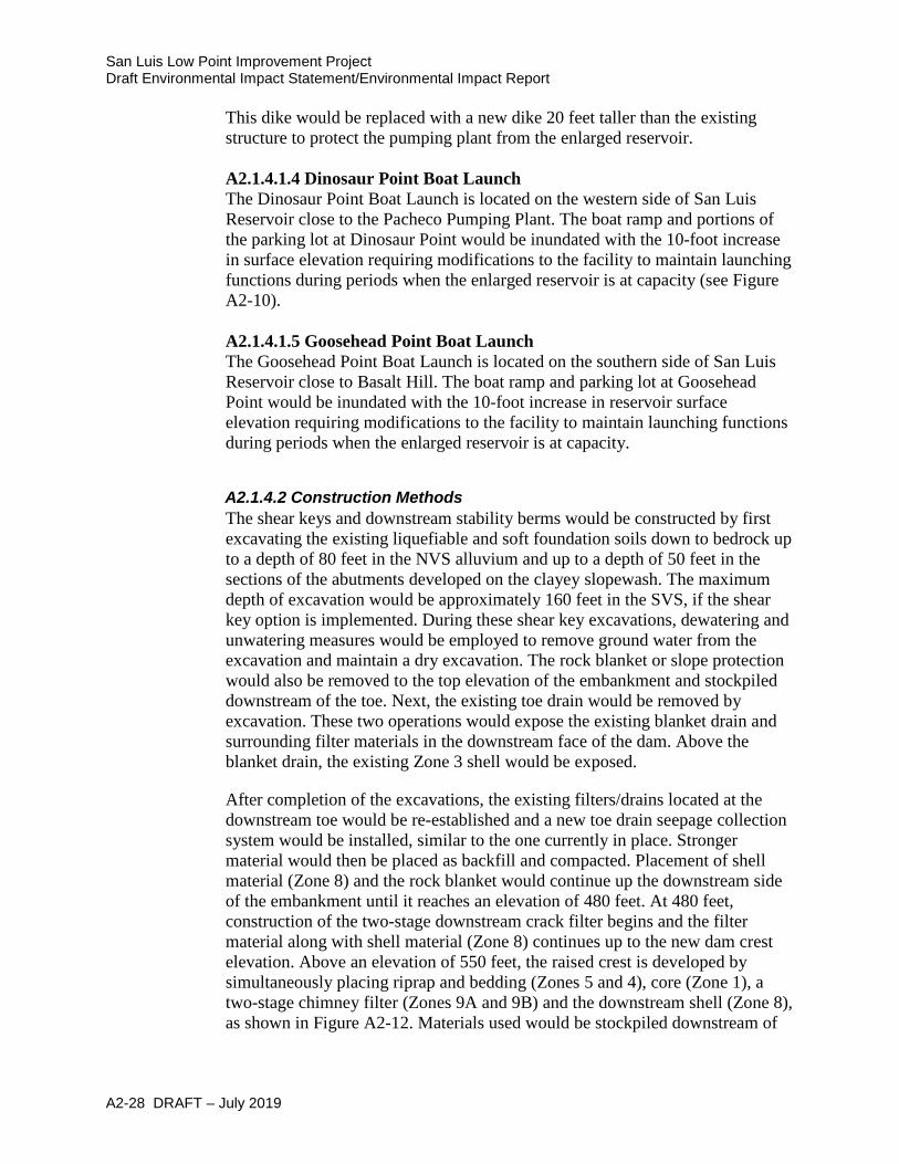
A2.1.4.5 Operation of the Reservoir Expansion Alternative The San Luis Reservoir Expansion Alternative would provide approximately 9,600 AF of additional south of Delta CVP water supply on an average annual basis compared to No Action. Figure A2-13 shows how the San Luis Reservoir Expansion Alternative addresses SCVWD low point water supply interruptions along with treated water demand shortages in the No Action Alternative. Results show that the San Luis Reservoir Expansion Alternative would not fully replace interrupted water supply but would provide some additional water in 8 of the 17 low point years.
Chapter A2 Project Description
A2-33 DRAFT – July 2019
Figure A2-13. Annual Shortages Addressed by San Luis Reservoir Expansion Alternative
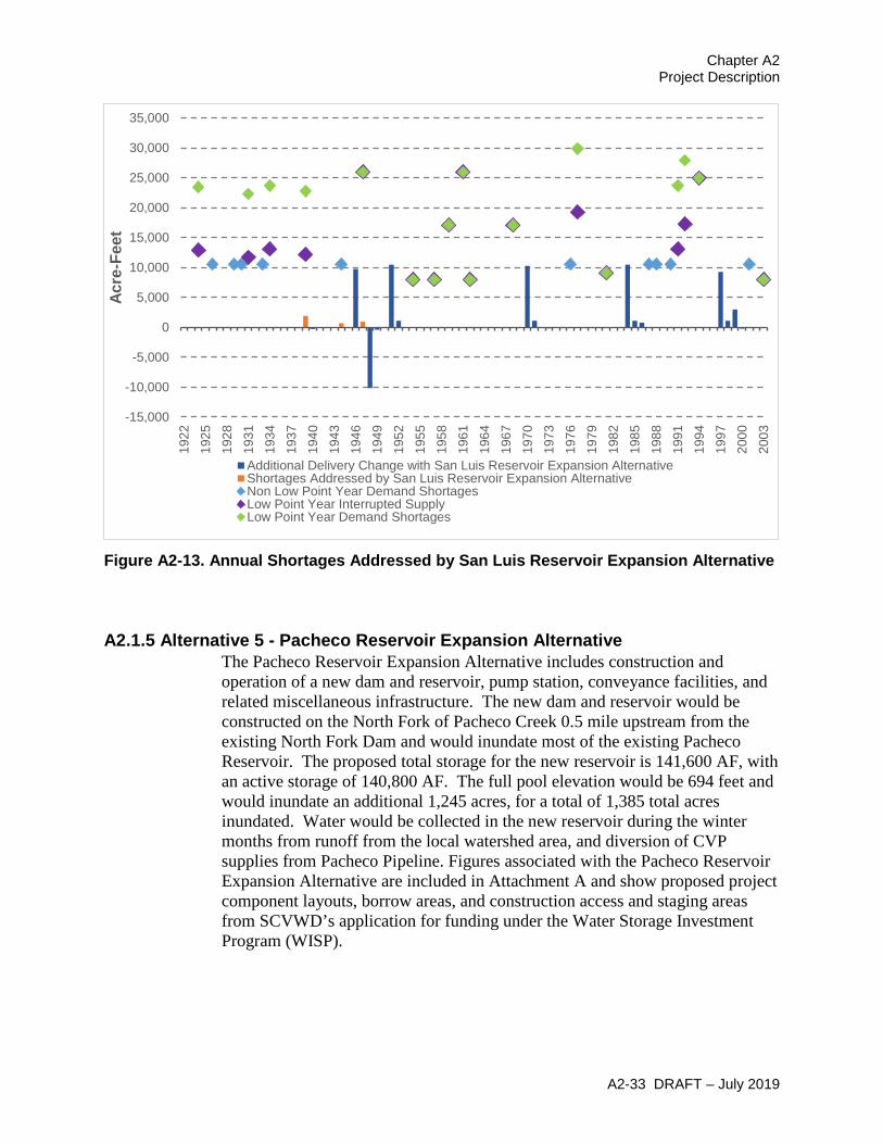
A2.1.5 Alternative 5 - Pacheco Reservoir Expansion Alternative The Pacheco Reservoir Expansion Alternative includes construction and operation of a new dam and reservoir, pump station, conveyance facilities, and related miscellaneous infrastructure. The new dam and reservoir would be constructed on the North Fork of Pacheco Creek 0.5 mile upstream from the existing North Fork Dam and would inundate most of the existing Pacheco Reservoir. The proposed total storage for the new reservoir is 141,600 AF, with an active storage of 140,800 AF. The full pool elevation would be 694 feet and would inundate an additional 1,245 acres, for a total of 1,385 total acres inundated. Water would be collected in the new reservoir during the winter months from runoff from the local watershed area, and diversion of CVP supplies from Pacheco Pipeline. Figures associated with the Pacheco Reservoir Expansion Alternative are included in Attachment A and show proposed project component layouts, borrow areas, and construction access and staging areas from SCVWD’s application for funding under the Water Storage Investment Program (WISP).
-15,000
-10,000
-5,000
0
5,000
10,000
15,000
20,000
25,000
30,000
35,000
1922
1925
1928
1931
1934
1937
1940
1943
1946
1949
1952
1955
1958
1961
1964
1967
1970
1973
1976
1979
1982
1985
1988
1991
1994
1997
2000
2003
Acre
-Fee
t
Additional Delivery Change with San Luis Reservoir Expansion AlternativeShortages Addressed by San Luis Reservoir Expansion AlternativeNon Low Point Year Demand ShortagesLow Point Year Interrupted SupplyLow Point Year Demand Shortages

San Luis Low Point Improvement Project Draft Environmental Impact Statement/Environmental Impact Report
A2-34 DRAFT – July 2019
A2.1.5.1 Pacheco Reservoir Expansion Project Facilities The Pacheco Reservoir Expansion Alternative would include the removal of the existing dam, development of a new earthen dam and spillway, expansion of the existing reservoir, new pipelines and tunnels, a new pump station, and associated channel modifications, a new regulating tank at Pacheco Pumping Plant, and access improvements.
A2.1.5.1.1 Dam and Spillway The new embankment dam would be a zoned earthfill structure consisting of an impervious core, flanked by an outer shell of random fill. A system of filters and drains would be provided to control seepage through the dam and foundation. A downstream sand chimney filter would protect the impervious core. A gravel chimney drain located downstream of the chimney filter would convey drainage to a gravel blanket beneath the downstream random fill zone. The gravel blanket drain would convey seepage from the impervious core and overlie form the foundation beneath the downstream random fill zone to the downstream toe of the dam. Sand filter zones would be placed above and beneath the gravel blanket drain to protect the gravel drain from contamination of the overlying random fill and underlying foundation materials. The upstream slope of dam would be protected from reservoir wave action by a 3-foot thick riprap layer.
An uncontrolled side channel spillway with a trapezoidal cross section would be located adjacent to the right (west) abutment of the proposed dam. Due to the relatively steep topography at the dam site, a side channel spillway would reduce the amount of excavation required in order to accommodate the spillway control weir. The spillway features include an approach channel, discharge chute and stilling basin, all of reinforced concrete and founded on bedrock. The side channel spillway entrance would include an ogee weir. A flip bucket located at the end of the stilling basin would dissipate the remaining energy in the basin during high discharge events. After leaving the deflector bucket, spillway discharges would be conveyed through a riprap lined outlet channel into the restored Pacheco Creek channel (see below description).
A2.1.5.1.2 Inlet/Outlet Facilities The inlet/outlet facilities would consist of a sloping intake/outlet structure and a low-level inlet/outlet designed to provide deliveries to the reservoir from Pacheco Conduit and withdrawals from the reservoir to the conduit and the north Fork of Pacheco Creek. However, these facilities would not be operated to facilitate these flows at the same time. For withdrawals from the reservoir, under normal operating conditions, this inlet/outlet facility would need to simultaneously convey up 490 cubic feet per second (cfs) to Pacheco Conduit and release up to 35 cfs to Pacheco Creek. The inlet/outlet conveyance facilities have been sized to accommodate up to 1,350 cfs under emergency drawdown conditions. During emergency conditions, the outlet works would serve as an evacuation outlet for reservoir draw down.

Chapter A2 Project Description
A2-35 DRAFT – July 2019
A sloping intake structure would be located north of the left (east) abutment and would consist of a single 132-inch diameter reinforced-concrete structure, with approximately 10 ports located at various elevations for drawing from the reservoir. A low-level reservoir inlet would also be constructed, with an inlet elevation of 450 feet, for reservoir drainage. A hydraulically operated gate valve structure would be located upstream of the reinforced-concrete sloping intake to allow for switching between reservoir delivery (through the tunnel) and withdrawal operations (through the outlet structure).
A 2,300-foot long conveyance tunnel would be constructed under the dam abutment to connect the intake structures and the pump station. The conveyance tunnel would be excavated through the bedrock on the left abutment of the dam. The control gatehouse structure would be used to regulate outlet flows from the reservoir to the pump station, for normal releases, and the discharge channel for stream augmentation and emergency releases.
To connect the new outlet works to Pacheco Creek, the historical Pacheco Creek channel would be restored between the new dam and the existing dam through the existing Pacheco Reservoir. Restoration of the channel would include excavating a new 1,500-feet long, 1.7-feet deep, one-foot wide, low-flow channel, and a 6-feet deep, 20-feet wide overbank channel to facilitate riparian restoration. The channel would be designed to reduce streambank erosion (e.g., using bank stabilizing materials), and riparian vegetation would be planted to initiate growth of a new riparian forest along the restored channel.
A2.1.5.1.3 Pacheco Reservoir Pump Station The Pacheco Reservoir Pump Station would serve as a two-way pump station that both delivers water to and withdraws water from the Pacheco Reservoir. The water surface elevation of the new reservoir would have an operating range of 450 feet to 694 feet; however, at the connection point to the Pacheco Conduit the total hydraulic head would be 610 feet. This requires a “two-way” system operating both by gravity and through a booster pump station.
The conveyance system would contain 10 feet of dynamic head loss that is included in the scenarios above. Isolation valves would enable the pump station to deliver water to, or pump water from, the reservoir. Pressure-reducing sleeve valves were identified as necessary to reduce excess pressure head under certain gravity-flow conditions. These valves would be used only when needed and bypassed at all other times. Additionally, pressure relief valves and discharge structures would be required to prevent over-pressurization of the existing Pacheco Conduit.
The pump station would be below the new dam. To provide security and minimize noise levels in the surrounding area, the pumps would be housed in a building. Space has been identified for other facilities on site, including intake, access, parking, surge tanks, power substation, yard piping, and construction staging.

San Luis Low Point Improvement Project Draft Environmental Impact Statement/Environmental Impact Report
A2-36 DRAFT – July 2019
The new pump station would need to meet a wide range of lift (0 to 160 feet static plus 10 feet dynamic) and high flow (490 cfs). A single pump station with multiple pump ranges has been proposed to meet these requirements—while preventing pump station horsepower (hp) duplication—limiting the amount of head burned by pump control valves and minimizing cost. A total of 11 pumps (10 duty plus 1 standby) are planned, however the pump configuration may be refined during future design studies. The pump motors would be sized for the first operating range (higher lift) at 1,250 hp each (13,750 total hp).
The 14 megavolt amp (MVA) substation for the new reservoir pump station is located in the Pacific Gas and Electric Company (PG&E) service area, with no other nearby service sources. PG&E has a 70 kilovolt (kV) transmission line that cannot support the additional 14 MVA connected load, and it would need to be upgraded to support the increased load. The existing 70 kV transmission line would be upgraded to two circuits, for use by the double-ended substation arrangement for this alternative.
A2.1.5.1.4 Conveyance from Pacheco Reservoir Pump Station to Pacheco Conduit A pipeline would be constructed to connect the new pump station located immediately downstream of the new dam and the existing Pacheco Conduit. The proposed pipeline would be 9 feet in diameter and about 4,700 feet long, with a pipeline design capacity of 490 cfs. This pipeline would allow for delivery of imported water from the Pacheco Conduit to the proposed reservoir for future release and would also provide for reservoir releases to the Pacheco Conduit.
Construction would be by conventional excavation, open trench, and backfill—except for the length of pipe located under SR 152. The length of pipe that would be located under SR 152 and Pacheco Creek would be installed using bore and jack techniques (i.e., tunneling techniques), to minimize impacts during construction. Construction spoils would be used on site for backfill as necessary, haul road development, and to support the dam crest raise. The tunnel, when completed, would be a 132-inch casing containing a 108-inch carrier pipe. There would also be permanent structures for appurtenances, such as air/vacuum valves, vaults, drains and blowoffs for the conveyance line.
The connection of the pipeline to the existing Pacheco Conduit would be southeast of the existing North Fork Dam. The connection would be with a tee in the Pacheco Conduit, with an isolation valve for the turnout (inlet and outlet) for the new reservoir.
A2.1.5.1.5 New Regulating Tank at Existing Pacheco Pumping Plant Controls to turn pumps on or off remotely would be based on the water level within Pacheco Reservoir and regulating tanks at the existing Pacheco Pumping Plant site near San Luis Reservoir. A second regulating tank at the existing Pacheco Pumping Plant site would be added adjacent to the existing regulating

Chapter A2 Project Description
A2-37 DRAFT – July 2019
tank to provide additional control buffer and surge control for the new Pacheco Reservoir Pump Station. The new regulating tank would match the elevation, diameter, and materials of the existing tank. This would add a second 10 AF, 150-feet diameter reservoir. Additional piping, valving, and controls would be required.
A2.1.5.2 Project Construction The environmental compliance, design, permitting, land acquisition, and financial and institutional arrangements are anticipated to be completed in 2023. Major construction is anticipated to take approximately five years from 2024 to 2028 with commissioning of system completed in late 2028. Miscellaneous improvements, such as road repairs, would continue through 2029.
A2.1.5.2.1 Borrow Areas Preparation of borrow areas would include the reservoir borrow areas, the spillway area, and the existing dam site prior to its removal. Preparation would include logging, stripping and disposal of topsoil, and implementation of any associated work access or material processing areas. It is assumed that the material processing areas could include a crushing and screening plant at the filter and drain borrow area and a concrete batch plant near the spillway excavation.
The area for impervious borrow materials would be located upstream of Turkey Flat, with material in this area classified as low-plasticity silt or clay. The potential random fill borrow area is just above Turkey Flat, and the material consists of a mix of silt, sand, gravel, and boulders. The proposed rock borrow area is along Pacheco Creek, just above Turkey Flat.
Approximately 5.75 miles of 25 feet-wide haul road would be required to access the reservoir borrow areas upstream of the embankment location. The haul road would follow an existing access road along Pacheco Creek that would need to be improved. Construction access roads totaling 4 miles and 25 feet wide would need to be constructed across the stream, downstream of the embankment, to access the spillway area. One and a half miles of these construction roads would improve existing access roads, providing permanent access to the site post-construction. An existing bridge over the stream would need to be improved.
A2.1.5.2.2 Inlet/Outlet Construction Construction of the tunnel and pipe between the inlet/outlet structure and pump station area would be accomplished as a site preparation activity; either by open-cut excavation, tunneling, or a combination of excavation and tunneling. The low-level intake would also be completed to allow diversion of the stream through the outlet structure for the duration of the following embankment construction. Construction of the outlet tunnel could include excavation for, and construction of, the pump station lower level, that would act as the energy

San Luis Low Point Improvement Project Draft Environmental Impact Statement/Environmental Impact Report
A2-38 DRAFT – July 2019
dissipation and discharge pipeline and channel to return flow to the stream below the dam.
Construction methods are anticipated to consist of clearing, grubbing, stripping, and disposal of topsoil; and grading consisting of excavation of soil and rock, filling, and compacting. Blasting of hard, fractured rock may be used to expedite excavation, but it is anticipated to be very limited during site preparation. Site preparation activities would include diversion of surface water, implementation of erosion and sediment controls, and establishment of a construction management area, including placement of temporary construction trailers. Site preparation activities may also include stabilization of potential or active landslide areas.
A2.1.5.2.3 Dam Construction Construction activities for the new dam and reservoir would include removing the existing North Fork Dam, and constructing a temporary cofferdam, new embankment dam, and spillway. Construction methods for dam removal and the cofferdam would consist of clearing, grubbing, stripping, and disposal of topsoil, and grading consisting of excavation of soil and rock, filling, and compacting. Construction methods for the new embankment and spillway include excavation and processing of borrow materials; hauling, placing and compacting fill and backfill; and forming and placing concrete.
Dam Removal The North Fork Dam is currently being operated under the terms of a DWR Division of Safety of Dams order requiring that the upstream and downstream outlet controls be maintained in the fully open position to maximize releases and maintain the lowest possible surface elevation in Pacheco Reservoir given the current condition of its spillway (DWR 2018). Construction of the Pacheco Reservoir Expansion Alternative would initiate with demolition of the existing North Fork Dam. Removal of the existing dam would proceed from the top down to prevent steep slopes and to minimize the potential for slope failure. Material excavated from the dam, deemed suitable for earth fill, would need to be directly hauled to the temporary cofferdam site for placement and compaction. Unsuitable material would be stockpiled for disposal off-site. Sand, gravel, cobbles, and rock may be segregated from the excavated material and used for site restoration. Bank stabilization and channel reconfiguration would be performed once the dam is removed, and any planned riparian and aquatic habitat enhancements would be implemented, such as creating pools, adding boulders, installing logs, and enhancing irregular edges.
Cofferdam The temporary cofferdam would be constructed at the upstream toe of the new dam footprint, following or concurrent with completion of the outlet construction, preferably during the dry season when flows in Pacheco Creek are low. The cofferdam crest elevation is 500 feet and was sized to ensure that

Chapter A2 Project Description
A2-39 DRAFT – July 2019
flows in Pacheco Creek are maintained during construction while accommodating at least a 20-year flood event and would accommodate the 50-year flood event. Foundation preparation for the cofferdam would be similar to that for the main embankment, and would consist of over-excavation of alluvium from the valley bottom and surficial soils along the abutments. The foundation and embankment of the cofferdam would be incorporated into the dam. Material used to construct the cofferdam would be imported from the random fill borrow sources, spillway excavation, and removal of the North Fork Dam.
Embankment Construction Initial preparation of the dam footprint would consist of clearing and grubbing of vegetation, removal of soft sediments and other deleterious materials, and shaping of the abutment side slopes. Form of slope protection may be needed to mitigate the potential for landslides and shallow-slope failures during construction. Dam foundation construction would include excavation of existing-channel alluvial materials to competent bedrock; loading and hauling excavated materials in the foundation footprint to stockpiles; cleaning of the foundation in the core and earth fill zones; surface treatment of the impervious-core foundation by excavating shear zones and backfilling with dental concrete/grout; and set-up, mix, and installation of a cutoff wall beneath the cores (grout curtain). Materials excavated from the foundation area could be stockpiled and reused in the earth fill areas of the embankment.
Embankment construction activities would include processing, excavating, loading, hauling, placing, and compacting of impervious core, adding earth fill, and draining and filtering of materials from borrow areas. Processing materials at the borrow sites would likely include, at a minimum, moisture conditioning. Drain and filter materials are anticipated to be sourced from local commercial vendors or facilities. Additional moisture conditioning may be required at the dam site as the materials are placed and compacted. It is anticipated that up to four concurrent material placement and compaction operations could be occurring at the same time as the embankment elevation is raised.
Spillway Construction Spillway construction would consist of completing excavation to final grades; formwork and placement of concrete for the base and walls of the entrance channel; chute and energy dissipation and stilling basin; and backfilling of walls, and final grading and erosion protection for the excavation slopes.
A2.1.5.2.4 Pump Station and Conveyance to Pacheco Conduit Construction Methods Construction methods for the pump station, surge tanks, and electrical substation would consist of excavation for basements, foundations, and building pads; preparing formwork and pouring concrete; installation of pumps and equipment; and final finishing of the interior. Construction of the conveyance pipeline to the Pacheco Conduit would generally consist of conventional trench

San Luis Low Point Improvement Project Draft Environmental Impact Statement/Environmental Impact Report
A2-40 DRAFT – July 2019
excavation and backfill. However, the section of the pipeline passing beneath SR 152 would be constructed using jack and bore trenchless methods.
Excavations to competent bearing material would need to be performed to construct the proposed pump station and appurtenant structures. The pump station and surge tanks are anticipated to be reinforced-concrete structures, and the electrical substation an open-graveled area with concrete mat and pedestal foundations for the electrical gear and towers. Security fencing would be required around all above-grade facilities.
A temporary and permanent construction easement would be required for the conveyance pipeline to the existing Pacheco Conduit. A potential corridor for the high-capacity electric transmission lines to the pump station could be located adjacent to the permanent easement from the pipeline. The pipeline would be constructed in an open-trench excavation and backfilled with imported bedding material and native backfill to existing grade. A series of permanent structures for appurtenances (i.e., air/vacuum valves, vaults, drains, and blowoffs) would be placed along the pipeline right-of-way. These structures would generally be below-grade and positioned directly over, or adjacent to, the conveyance pipeline.
Site access for the tunnel would include constructing new haul and access roads in conjunction with making improvements to existing roadways. Wherever possible, the alignment of these roads would follow the existing unimproved roads or four-wheel-drive trails. The access road from SR 152 to the dam site would be about 2.74 miles long. It is anticipated that the road would eventually be completed as an approximately 40-feet wide, asphalt-paved, two-lane road. Preparing a temporary construction road with this width would allow two-way traffic during construction.
A2.1.5.3 Operation of the Pacheco Reservoir Expansion Alternative The expanded Pacheco Reservoir would be primarily filled using natural inflows from the North and East Forks of Pacheco Creek. These inflows are typically realized from December through March. Supplemental flows to the expanded reservoir would arrive from SCVWD’s share of contracted CVP pumped water from San Luis Reservoir. This would include allocated CVP water supplies that otherwise could not be delivered to or stored by SCVWD. This CVP water supply would be pumped from the Pacheco Conduit up to the expanded Pacheco Reservoir earlier in the year prior to the summer months when the San Luis Reservoir is typically drawn down to the 300 TAF level. The rate at which these transfers are made between San Luis Reservoir and Pacheco Reservoir would depend upon water rights, supply allocations, water demands, availability of other water supplies, and conveyance limitations of Pacheco Conduit. Conveyance and storage of these CVP supplies is anticipated to occur primarily in wet years. CVP water stored in Pacheco Reservoir could then be

Chapter A2 Project Description
A2-41 DRAFT – July 2019
released through the summer while supplies from San Luis Reservoir would be inaccessible to SCVWD.
Alternative 5 would be operated by SCVWD to improve habitat conditions for steelhead in Pacheco Creek, improve SCVWD water supply reliability, including during drought periods and emergencies, and meet the groundwater recharge objectives of Pacheco Pass Water District (PPWD). Average monthly target flows ranging from 10 to 30 cfs in Pacheco Creek would support the biological needs of South-Central California Coast (SCCC) steelhead, which are listed as threatened under the Federal Endangered Species Act (ESA), for higher flows for outmigration. The average monthly release targets are shown in Table A2-2. During heavy precipitation events, releases from the expanded reservoir would be reduced to minimize flooding risks along Pacheco Creek and the Pajaro River. Winter releases of stored supply would be discontinued when it is estimated that there will be sufficient inflow passed through the reservoir downstream onto Pacheco Creek to provide for aquatic habitat going forward into the spring. The thresholds for discontinuing these winter releases are shown in Table A2-2. Operation of the expanded Pacheco Reservoir would not change the existing operations of the CVP.
To ensure that flows and water temperatures in Pacheco Creek are maintained in consecutive dry years, releases to Pacheco Conduit—to meet SCVWD water demands—would be discontinued in the event that reservoir storage volumes fall below 55,000 AF. This flow regime may however be altered in the event of an emergency declaration by SCVWD for health and safety purposes. These habitat flows would be secured by operations requirements expected in the biological opinion(s) that would be developed for the expanded Pacheco Reservoir, as well as the contract between DWR and SCVWD for the provision of grant funding through the WSIP, and in the contract between and DWR and SCVWD for the provision of grant funding through the WSIP, and in the multi-agency operations agreement between Reclamation and SCVWD for Pacheco Reservoir that would be developed during the pre-construction design phase for this alternative if it is selected for implementation.

San Luis Low Point Improvement Project Draft Environmental Impact Statement/Environmental Impact Report
A2-42 DRAFT – July 2019
Table A2-2. Average Monthly Release Targets to Pacheco Creek from Expanded Pacheco Reservoir
Month
Average Monthly Release Targets to Pacheco Creek
(cfs)1
Inflow into Pacheco Reservoir Needed to Discontinue Winter
Releases (cfs) January 10 11.2 February 10 11.2
March 20 22.4 April 20 22.4 May 12 13.4 June 13 NA July 14 NA
August 14 NA September 14 NA
October 14 NA November 10 11.2 December 10 11.2
Notes: 1 Releases from Pacheco Reservoir are reduced during high flows in the south fork of Pacheco Creek. Key: CFS = cubic feet per second
In addition, SCVWD would transfer 2,000 AF of its CVP water contract allocation (in below normal water years), directly or through transfer and exchanges, in perpetuity to Reclamation and U.S. Fish and Wildlife Services’ Refuge Water Supply Program (RWSP), for use in the Incremental Level 4 water supply pool for wildlife refuges. This long-term voluntary reallocation of CVP yield by SCVWD would be secured by an agreement between the U.S. Fish and Wildlife Service (USFWS) and SCVWD detailing the mechanisms and timing for delivery of this supply, a contract between DWR and SCVWD for the provision of grant funding through the WSIP specific to this refuge water supply that would require the provision of these supplies in perpetuity, and an multi-agency operations agreement between Reclamation and SCVWD for Pacheco Reservoir to deliver and store SCVWD’s CVP supply in this new facility that would also include the requirements for this transfer.
While Reclamation sets priorities for Incremental Level 4 distribution, SCVWD has expressed its desire that the transferred water be designated to refuges supported by Grassland Resources Conservation District (GRCD). The water would be used to flood wetlands, directly benefiting wetland-dependent wildlife populations. The delivery schedule of this water would be flexible, but could be delivered as early as March or April. This water could be stored in San Luis Reservoir, providing the RWSP greater flexibility in making late season deliveries to refuges. For deliveries to GRCD, deliveries would be made to Los Banos through the Delta-Mendota Canal.
SCVWD would use Pacheco Reservoir Expansion Alternative for operational storage within their system as well as for emergency supply. SCVWD accesses its CVP water through the Pacheco Conduit. Pacheco Reservoir Expansion

Chapter A2 Project Description
A2-43 DRAFT – July 2019
Alternative includes construction of an inlet/outlet facility connecting to then the conduit that takes water from Pacheco Conduit to the expanded Pacheco Reservoir as well as from the expanded Pacheco Reservoir to Pacheco Conduit. During years when SCVWD water supplies exceed the water demands in the SCVWD service areas and excess storage capacity is available in the expanded reservoir, SCVWD would convey CVP supplies from San Luis Reservoir through Pacheco Conduit and into the expanded Pacheco Reservoir. Conveyance and storage of these CVP supplies is anticipated to occur primarily in wet years. The rate at which these transfers are made between San Luis Reservoir and Pacheco Reservoir would depend on supply allocations, water demands, and availability of other water supplies.
Under this alternative, modeling results have predicted that there would be 17 years (out of the 82 modeled years) where the reservoir would be drawn below 300 TAF of storage i.e. low point years. Figure A2-14 shows how the Pacheco Reservoir Expansion Alternative addresses SCVWD low point water supply interruptions along with treated water demand shortages in the No Action Alternative. Results show that the Pacheco Reservoir Expansion Alternative would allow uninterrupted delivery of SCVWD CVP M&I deliveries 14 out of the 17 low point years when compared to the No Action/No Project Alternative, partially reducing SCVWD unmet demand during low point events.
Figure A2-14. Annual Shortages Addressed by Pacheco Reservoir Expansion Alternative
0
5,000
10,000
15,000
20,000
25,000
30,000
35,000
1922
1925
1928
1931
1934
1937
1940
1943
1946
1949
1952
1955
1958
1961
1964
1967
1970
1973
1976
1979
1982
1985
1988
1991
1994
1997
2000
2003
Acre
-Fee
t
Shortages Addresses by Pacheco Alternative Non Low Point Year Demand ShortagesLow Point Year Interrupted Supply Low Point Year Demand Shortages

San Luis Low Point Improvement Project Draft Environmental Impact Statement/Environmental Impact Report
A2-44 DRAFT – July 2019
A2.2 References
California Department of Water Resources (DWR). 2018. Second Notice Regarding Necessary Repairs. Letter from Sharon Tapia, Chief Division of Safety of Dams to Frank O’Connell, President Pacheco Pass Water District. April 6, 2018.
United States Department of the Interior, Bureau of Reclamation (Reclamation). 2013. San Luis Reservoir Expansion Draft Appraisal Report. December 2013. Accessed on 09/12/2016. Available at: https://www.usbr.gov/mp/sllpp/docs/2013_11_19_DRAFT_San_Luis_Expansion_Appraisal_Report.pdf.

Attachment A: Project Description Support Pacheco Reservoir Expansion Project Facilities

This page left blank intentionally.


MA
X. W
AT
ER
S
UR
FA
CE
E
LE
VA
TIO
N O
F 6
94
F
T
Exh
ib
it 2
LA
ND
A
CQ
UIS
IT
IO
N B
OU
ND
AR
Y
SC
AL
E:
PE
RM
AN
EN
T P
IP
EL
IN
E E
AS
EM
EN
T B
OU
ND
AR
Y
PR
OJE
CT S
ITE FE
ATU
RE
S
EX
IS
TIN
G P
AC
HE
CO
C
ON
DU
IT
1"=
50
0'
P
AC
HE
CO
R
ES
ER
VO
IR
E
XP
AN
SIO
N P
RO
JE
CT
PA
CH
EC
O A
ND
N
OR
TH
F
OR
K P
AC
HE
CO
C
RE
EK
N
0
50
0
PA
CH
EC
O A
ND
N
OR
TH
F
OR
K P
AC
HE
CO
C
RE
EK
AU
GU
ST
2017


ELE
VA
TIO
N (F
EE
T)
900
DAM CREST EL. 719
800
UPSTREAM CHIMNEY FILTER
DOWNSTREAM CHIMNEY FILTERS
MAX. WATER SURFACE EL. 694
DOWNSTREAM CHIMNEY DRAIN
700
1' BEDDING
3
2.5
3' RIP RIP
1
EARTH
.5 1
.25
600 INSTALL DRAINAGE
FILL
1 CONVEYANCE
COFFER DAM CREST EL. 500
1
EARTH
SYSTEM AT TOE
CORE
2.5
500 DEAD POOL
FILL
1
TEMPORARY
EL. 450
COFFER DAM
400
1
SEE DETAIL
EXISTING GRADE AT EL. 400
300
GROUT CURTAINS
9
1,000
0
SCALE:
2,000
1"=150'
HORIZONTAL DISTANCE (FEET)
0 75 150
CROSS SECTION OF ZONED DAM EMBANKMENT
COARSE SAND/GRAVEL
EARTH FILL
6' GRAVEL DRAIN
3' BLANKET FILTERS
CORE
FINE SAND FILTERS
DETAIL 1
NTS
9
Exhibit 4
CROSS SECTION OF DAM EMBANKMENT PACHECO RESERVOIR EXPANSION PROJECT
AUGUST 2017

EXISTING GRADE AT SPILLWAY CENTERLINE
PROPOSED DAM
2%
100'
TRANSITION TO
TRANSITION
RECTANGULAR CHANNEL
1
1
1
2
2,000
1,000
900
700
600
500
0
800
500
400
HORIZONTAL DISTANCE (FEET)
EL
EV
AT
IO
N (F
EE
T)
STILLING BASIN
SIDE CHANNEL
SPILLWAY WEIR
PROPOSED SPILLWAY
FLIP BUCKET
SIDE CHANNEL
SPILLWAY WEIR
EL. 694'
SPILLWAY PROFILE
PACHECO RESERVOIR EXPANSION PROJECT
AUGUST 2017
Exhibit 5
SCALE:
1"=150'
0 75 150


HIGHWAY 152 TUNNEL
500
400
0
GRAVITY FLOW TO PACHECO RESERVOIR
5,000
EXISTING GRADE
GRAVITY FLOW HGL
TO PACHECO
RESERVOIR
PACHECO
RESERVOIR
700
600
PACHECO
REGULATING
TANK
HGL FOR PUMPING
TO PACHECO
RESERVOIR
PACHECO
RESERVOIR
PUMP TO PACHECO RESERVOIR
EXISTING GRADE
500
400
700
600
0
"NEW" PACHECO
PUMP STATION
5,000
PRIMARY PUMPING
RANGE
CONNECTION TO
EXISTING PACEHCO
CONDUIT
EXISTING GRADE
400
0
PACHECO
RESERVOIR
600
500
700
GRAVITY FLOW TO PACHECO CONDUIT
5,000
GRAVITY FLOW HGL
TO PACHECO CONDUIT
CONNECTION TO
EXISTING PACEHCO
CONDUIT
PRIMARY PUMPING
RANGE: 526' TO 620'
GRAVITY FLOW HGL
500
400
0
SECONDARY PUMPING
RANGE: 450' TO 526'
"NEW" PACHECO
PUMP STATION
5,000
EXISTING GRADE
PACHECO
RESERVOIR
700
600
CONNECTION TO
EXISTING PACEHCO
CONDUIT
PUMP TO PACHECO CONDUIT
HIGHWAY 152 TUNNEL
HIGHWAY 152 TUNNEL HIGHWAY 152 TUNNEL
PACHECO
REGULATING
TANK
CONNECTION TO
EXISTING PACEHCO
CONDUIT
NOTES:
GRAVITY FLOW FROM PACHECO
CONDUIT TO PACHECO RESERVOIR
CAN BE ACHIEVED WHEN RESERVOIR
ELEVATION IS APPORXIMATELY
BELOW 600 FT.
NOTES:
PUMPS WOULD OPERATE TO DELIVER
WATER FROM PACHECO CONDUIT
TO PACHECO RESERVOIR WHEN THE
RESERVOIR ELEVATION IS
APPROXIMATELY ABOVE 600 FT.
NOTES:
GRAVITY FLOW FROM PACHECO
RESERVOIR TO PACHECO CONDUIT
CAN BE ACHIEVED WHEN RESERVOIR
ELEVATION IS APPROXIMATELY
ABOVE 620 FT.
NOTES:
PUMPS WOULD OPERATE TO DELIVER
WATER FROM PACHECO RESERVOIR
TO PACHECO CONDUIT WHEN THE
RESERVOIR ELEVATION IS APPROXIMATELY
BELOW 620 FT.
HGL FOR PUMPING
TO PACHECO
CONDUIT
Exhibit 8
PUMP/GRAVITY HYDRAULIC PROFILE
PACHECO RESERVOIR EXPANSION PROJECT
AUGUST 2017
SCALE
HOR: 1" = 2,000'
VERT: 1" = 100'

PARKING
ELECTRICAL ROOM
OPERATIONS & HVAC
ROOM
ELECTRICAL SUBSTATION
150'
150'
100'
220'
50'
150'
150'
AREA = 3.5 ACRES
345'
440'
25'
ACCESS ROAD
FENCE
SURGE TANKS
28,000 CF TOTAL
(7 TANKS)
TO/FROM PACHECO
RESERVOIR
TO/FROM PACHECO
CONDUIT
PUMP STATION
15' x 15'
VAULT BOX
(TYP.)
50'
50'
NOTES:
1) SURGE ANALYSIS WILL BE PERFORMED TO DETERMINE THE SIZE AND NUMBER
OF SURGE TANKS REQUIRED, DURING SUBSEQUENT STUDIES
120'
GATEHOUSE
AND RELEASE
TO CREEK
N
Exhibit 9
PUMP STATION LAYOUT
PACHECO RESERVOIR EXPANSION PROJECT
AUGUST 2017


MA
X. W
AT
ER
S
UR
FA
CE
E
LE
VA
TIO
N O
F 6
94
F
T
Exh
ib
it 1
2
EX
IS
TIN
G P
AC
HE
CO
C
ON
DU
IT
IM
PR
OV
EM
EN
T O
F E
XIS
TIN
G A
CC
ES
S R
OA
D
SC
AL
E:
IM
PR
OV
EM
EN
T O
F
CO
NS
TRU
CTIO
N A
CC
ES
S A
ND
STA
GIN
G A
RE
AS
(P
ER
MA
NE
NT
)
N
EX
IS
TIN
G A
CC
ES
S R
OA
D
1"=
50
0'
PA
CH
EC
O R
ES
ER
VO
IR
E
XP
AN
SIO
N P
RO
JE
CT
(T
EM
PO
RA
RY
)
NE
W A
CC
ES
S R
OA
D (P
ER
MA
NE
NT
)
0
50
0
AU
GU
ST
2017
NE
W A
CC
ES
S R
OA
D (T
EM
PO
RA
RY
)
PO
TE
NT
IA
L S
TA
GIN
G A
RE
AS