sampling and testing of industrial waters
TRANSCRIPT

Industrial waters - quality assurance – sampling and testing
Chandran Udumbasseri, Technical consultant
Introduction
Industrial waters include boiler water, cooling tower water, condensate water,
make up water and waste water. The treatments differ in all these areas as their
purpose differ as industrial water. The treatments are monitored through regular
testing and analysis
Regular, representative sampling and accurate testing are essential parts of a
sound industrial water treatment program. This is to ensure that proper chemical
levels are maintained and the pH of the water is within the set range.
Quality assurance sample analysis
1. A boiler of capacity 100 HP or greater capacity needs quality assurance
each month.
2. All boilers treated with caustic, phosphate and sulfite should be checked
for the boiler water treatment level by collecting 1Lt of representative
sample.
3. For boilers of low capacity (les than 15psig), the caustic level must be
checked.
4. 1Lt sample should be taken for hot water boilers for testing purpose.
In plant testing
Test kits should be used for in plant testing (field testing)
Sampling and testing of cooling towers
Collect samples in clean plastic bottles and conduct the tests without delay.
In re-circulating cooling towers, sample may be taken by dipping in cold well or
from re-circulating pump discharge.
Frequency of samples
The table given below shows the sample frequency and the required tests.
pH M-
Alkalinity
Conductivity
(TDS)
Calcium
Hardness
Inhibitor
Make up - 1/w 1/w 1/w -
Small CT,
(<25 Ton)
1/w 1/w 1/w 1/w 1/w
Medium CT
(25-100 Ton)
2/w 2/w 2/w 2/w 2/w
Large CT
(>100 Ton)
1/D 1/D 1/D 1/D 1/D
Notes: w = week; D = Day The main tests for cooling towers are:
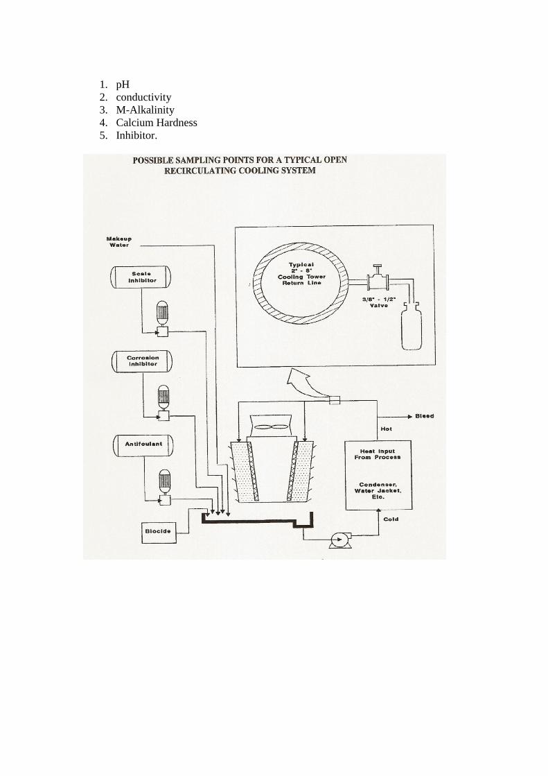
1. pH
2. conductivity
3. M-Alkalinity
4. Calcium Hardness
5. Inhibitor.

Sampling and testing of Boilers
Method of sampling
1. Cool the sample using sample cooler to get a representative sample.
2. Sample Cooler: A coil of 15-20 feet made out of copper or stain steel
tubing can be used as sample cooler. The coil can be immersed in a
permanent cooling jacket or it may be immersed in a bucket of cold
water. Keep a slow flow rate so that the sample gets cooled to ambient
temperature during its flow through the coil.
3. Sampling procedure:
3.1. Cool the cooling coil before taking boiler water sample.
3.2. Flesh the coil with boiler water for several times before collecting the
representative sample.
3.3. Extend the end of sample coil to the bottom of the sample bottle and
allow at least one volume of the bottle water to over flow from
container during the collection process. Plastic bottle are the
preferred containers (glass bottles should not be used if silica content
is limited)
Frequency of sampling and testing
The sample and frequency for boiler systems is given in the table
pH Total
Alkalinity
Hydroxyl
Alkalinity
Calcium
Hardness
TDS Copper
content
Ortho
phosphate
Sulfite
content Make up
water
- 1/w - 1/w 1/w - - -
Boiler
feed
water
(<25HP)
- 1/w - 1/w 1/w - - -
BFW
(25-
100HP)
- 2/w - 2/w 2/w - - -
BFW
(>100
HP)
- 1/D - 1/D 1/D - - -
Boiler
water
(25HP)
1/w - 1/w - 1/w - 1/w 1/w
BW (25-
100HP)
2/w - 2/w - 2/w - 2/w 2/w
BW
(.100HP)
1/D - 1/D - 1/D - 1/D 1/D
Condens-
ate
Return
Small
1/w - - -- 1/w 1/q - -
CR
Medium
2/w - - - 2/w 2/q - -
CR
Large
1/D - - - 1/D 1/q - -

Sampling location
1. Make up water: from the output of the softener
2. Boiler Feed water: from the discharge of boiler feed pump
3. Boiler water: from the continuous blow down line (between the boiler
and regulating valve)
4. Steam condensate: from the line that enter the deaerator
5. Steam samples: they are rarely taken; it can be taken from steam header
using sample cooler.
Feed water sample
Feed water may be checked for the following parameters:
1. M-Alkalinity
2. Conductivity
3. Calcium hardness.
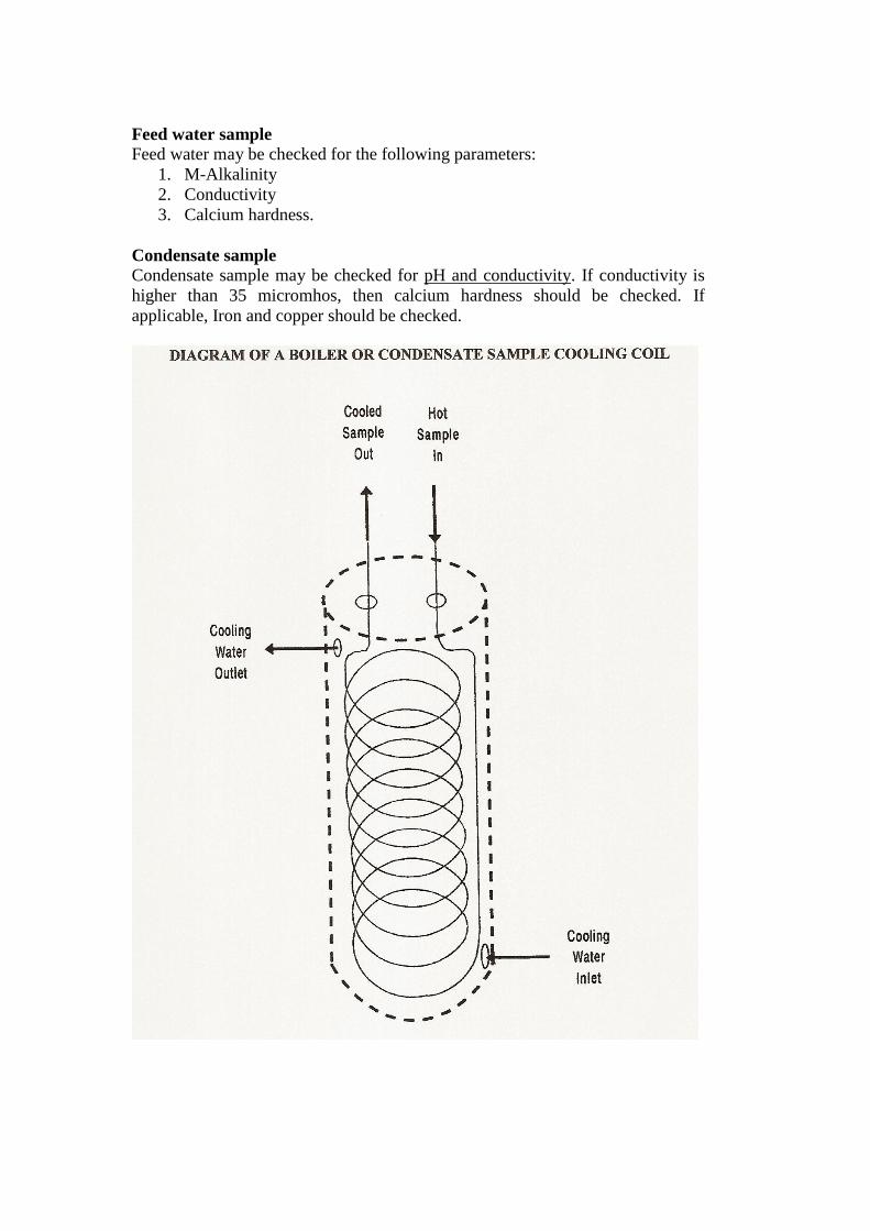
Condensate sample
Condensate sample may be checked for pH and conductivity. If conductivity is
higher than 35 micromhos, then calcium hardness should be checked. If
applicable, Iron and copper should be checked.

Blow down sample
Blow down sample should be checked for the following parameters:
1. OH Alkalinity
2. Neutralized Conductivity
3. Ortho Phosphate
4. Sulfite
Sampling and testing other water systems
Hot and chilled circulating water
The testing frequency is given in the following table.
Additional points to be noted are:
1. Make up water to hot water boilers, chilled water systems and diesel
engine jackets usually comes from an ion exchange unit or dealkalizer
unit.
2. Re-circulating water from HTW (high temperature hot water boilers)
systems and systems using the sulfite caustic soda treatment program
should be tested once per day fro pH and sulfite.
3. Re-circulating chilled and hot water treated with nitrite-borax or
Molybdate-caustic program should be checked once per month for nitrite
or Molybdate content and pH.
Ion exchangers and dealkalizers
The testing frequency for these systems is given in the following table.
Additional points to be noted are:
1. The incoming water to ion exchanger should be checked for Total
Hardness once per week. The dealkalizer influent should be checked for
Total (M) alkalinity once per week.
2. The effluent from these exchangers should be checked for reduction in
hardness and reduction in total alkalinity once per day or once per shift.
3. The location of sample point is important to get proper representative
sample. If multi-port valves are used for automatic regeneration then
these are possibilities of sample to get mixed of incoming and outgoing
waters.
4. The brine used for regeneration should be tested by hydrometer to
measure its strength. It should be of 100% saturation ( 28% strength)
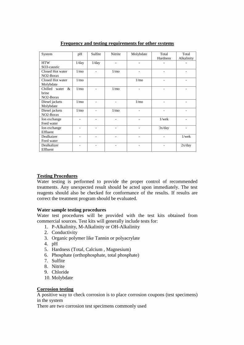
Frequency and testing requirements for other systems
System pH Sulfite Nitrite Molybdate Total
Hardness
Total
Alkalinity
HTW
SO3-caustic
1/day 1/day - - - -
Closed Hot water
NO2-Borax
1/mo - 1/mo - - -
Closed Hot water
Molybdate
1/mo 1/mo - -
Chilled water &
brine
NO2-Borax
1/mo - 1/mo - - -
Diesel jackets
Molybdate
1/mo - - 1/mo - -
Diesel jackets
NO2-Borax
1/mo - 1/mo - - -
Ion exchange
Feed water
- - - - 1/wek -
Ion exchange
Effluent
- - - - 3x/day -
Dealkaizer
Feed water
- - - - - 1/wek
Dealkalizer
Effluent
- - - - - 2x/day
Testing Procedures
Water testing is performed to provide the proper control of recommended
treatments. Any unexpected result should be acted upon immediately. The test
reagents should also be checked for conformance of the results. If results are
correct the treatment program should be evaluated.
Water sample testing procedures
Water test procedures will be provided with the test kits obtained from
commercial sources. Test kits will generally include tests for:
1. P-Alkalinity, M-Alkalinity or OH-Alkalinity
2. Conductivity
3. Organic polymer like Tannin or polyacrylate
4. pH
5. Hardness (Total, Calcium , Magnesium)
6. Phosphate (orthophosphate, total phosphate)
7. Sulfite
8. Nitrite
9. Chloride
10. Molybdate
Corrosion testing
A positive way to check corrosion is to place corrosion coupons (test specimens)
in the system
There are two corrosion test specimens commonly used

1. Corrosion test coupons for use in open and closed cooling systems,
closed hot water systems and domestic water systems.
2. Corrosion pipe inserts for use in steam condensate return systems
Corrosion test results are reported as a rate of corrosion penetration in to the
metal given in mils penetration per year (mpy)
A mills is one-thousandth (0.001) inch. Thus the corrosion rate of 10mpy means
that the thickness of a metal is reduced by 10x0.001 = 0.01 inches per year.
If the metal being studied is 1/16 or 0.0625 inches thick, this means that it will be
completely destroyed in just over 6 years.
Corrosion rate may also be expressed in millimeters per year (mmpy).
1 mpy = 0.0254 mmpy
1mmpy = 39.4 mpy.
Corrosion is also given a weight loss in milligram per square decimeter per
day (mdd)
For steel, the relation between penetration and weight loss is
1mdd = 0.2 mpy
1 mpy = 5 mdd
There are a variety of electrical instruments available which monitor and record
corrosion rates.
Corrosion coupons
The coupons are tags of various sizes. Generally low carbon steel specimens are
used as the most susceptible metal to corrosion. Other metals like copper,
stainless steel, brass and other metals are available
Weight loss:
The specimens are cleaned and then weighed. The general corrosion is
determined after exposure to the system. The coupons are again cleaned and
reweighed to find the weight loss.
Corrosion rate is calculated using weight loss, duration of exposure and area of
the coupon exposed.
Water velocity:
The coupons should be exposed to conditions that reflect those in the system as
whole. Water temperature and flow velocity will affect the results.
The corrosion rate will increase when velocity is too low or too high. For best
results the water velocity should be 3 to 5ft/sec.
Water temperature:
The corrosion increases with temperature. So in cooling water systems both the
cold water supply and hot return should be evaluated by coupon. The coupon
should be installed in the incoming hot water line and cold water going in to the
system.
Coupon exposure duration:
Usually the exposure time is for a minimum of 30 calendar days and maximum
of 90 calendar days.
Scheduling:
A regular schedule can determine the trends and recognize changes within the
system
While installing test specimens of different metals, the more resistant metals
(noble metals) should be installed down stream of less resistant metals.
Specimen shipment and storage:
The specimens are shipped in vapor inhibiting bags. The specimens should be
removed only at the time of installation. Use the same type of bag for returning
the exposed specimens.
Do not handle specimens with fingers since finger prints can initiate corrosion
sites.
Installing the specimens:
While installing the specimen into the system note the location and date of
installation.
After the exposure to the desired time carefully remove the specimen, air dry
without disturbing any deposits and return to the original vapor inhibited bags.
Record the removal date and send for evaluation.
Installation of coupons
Coupons are usually installed in pipe “Tees” by means of corrosion test racks
which include a 1 inch pips plug, drilled and tapped to accept a plastic or
phenolic rod with a nylon nut and bolt for attaching the coupon to the rod.
A by pass arrangement with 1 inch piping will facilitate installation and removal.
Poly vinyl chloride will eliminate electrical effects but cannot be used for hot
condensate.
For steam and condensate return line, installation is made where “Tees” are
present.
When using bypass arrangement, condensate from the outlet is piped back into
the system.
Bypass should be constructed of iron pipe and fittings and installed where there
is sufficient pressure differential to ensure a continuous flow through the bypass.
Important points are:
1. Flow through the corrosion test rack should be continuous and
measurable. (Flow meter).
2. The flow through the rack may be maintained at 3 to5 ft/sec.
3. The direction of flow should be as shown in the figure.

Interpretation of Tests
Many water treatment systems require that a specific level of a treatment
chemical be carried in the water. When a test indicates that a chemical is not
within the limits required for the treatment program confirm that the test was
performed properly and is valid.
When the test shows results at a lower level than required, evaluate the chemical
addition program and make the appropriate adjustment.
If adjustments do not correct the situation, then evaluate the system in total to
determine the nature of the problem.
When the results are too high then also check the chemical addition program.
Reduce the addition rate to bring the results the required level.
If test for hardness is found high then check the make up water treatment
program.
Alkalinity relationships
The three basic sources of alkalinity in water are:
1. Alkalinity resulting from bicarbonate (HCO3)
2. Alkalinity from carbonate (CO3)
3. Alkalinity from hydroxyl ion (OH)

The amount of each of these in water can be determined by titrating with an acid
to certain pH levels using phenolphthalein (P Alkalinity) and methyl orange (M
alkalinity) end points.
Relationship of P, M, and OH alkalinities
P and M alkalinities can be determined by titration and OH alkalinity can be
calculated. OH alkalinity is also known as caustic alkalinity.
Alkalinity relationship based on P and M tests
Conditions OH Level of alkalinity
contributed by
carbonate
bicarbonate
P = M M 0 0
P > M/2 2P-M 2(M-P) 0
P = M/2 0 M 0
P<M/2 0 2P M-2P
P = 0 0 0 M
Example 1
P=86ppm; M=118ppm
M/2 = 118/2 = 59ppm
So P>M/2
Then
OH alkalinity = 2x86-118 = 172 – 118 = 54
Causticity = OH alkalinity/3
So Causticity = 54/3 = 18ppm
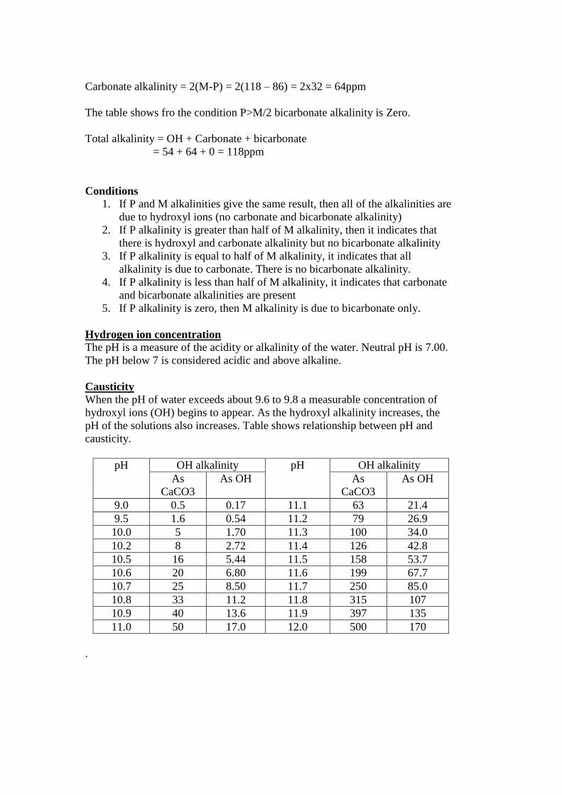
Carbonate alkalinity = 2(M-P) = 2(118 – 86) = 2x32 = 64ppm
The table shows fro the condition P>M/2 bicarbonate alkalinity is Zero.
Total alkalinity = OH + Carbonate + bicarbonate
= 54 + 64 + 0 = 118ppm
Conditions
1. If P and M alkalinities give the same result, then all of the alkalinities are
due to hydroxyl ions (no carbonate and bicarbonate alkalinity)
2. If P alkalinity is greater than half of M alkalinity, then it indicates that
there is hydroxyl and carbonate alkalinity but no bicarbonate alkalinity
3. If P alkalinity is equal to half of M alkalinity, it indicates that all
alkalinity is due to carbonate. There is no bicarbonate alkalinity.
4. If P alkalinity is less than half of M alkalinity, it indicates that carbonate
and bicarbonate alkalinities are present
5. If P alkalinity is zero, then M alkalinity is due to bicarbonate only.
Hydrogen ion concentration
The pH is a measure of the acidity or alkalinity of the water. Neutral pH is 7.00.
The pH below 7 is considered acidic and above alkaline.
Causticity
When the pH of water exceeds about 9.6 to 9.8 a measurable concentration of
hydroxyl ions (OH) begins to appear. As the hydroxyl alkalinity increases, the
pH of the solutions also increases. Table shows relationship between pH and
causticity.
pH OH alkalinity pH OH alkalinity
As
CaCO3
As OH As
CaCO3
As OH
9.0 0.5 0.17 11.1 63 21.4
9.5 1.6 0.54 11.2 79 26.9
10.0 5 1.70 11.3 100 34.0
10.2 8 2.72 11.4 126 42.8
10.5 16 5.44 11.5 158 53.7
10.6 20 6.80 11.6 199 67.7
10.7 25 8.50 11.7 250 85.0
10.8 33 11.2 11.8 315 107
10.9 40 13.6 11.9 397 135
11.0 50 17.0 12.0 500 170
.

Conductivity and total dissolved solids
In neutral or alkaline waters there is no consistent relationship between
conductivity and TDS.
If alkaline water is acidified to the phenolphthalein end point with organic acid
such as Gallic acid (which neutralizes causticity but does not contribute to
conductivity), the TDS is approximately equal to two-thirds the neutralized
conductivity in micromhos.
If synthetic organic polymer is used as sludge dispersant a value of 0.7 may be
used as conversion factor.
If Tannin us used then the conversion factor is 0.7 to 1.0 depending upon the
amount of Tannin used.
In-plant Laboratory requirements
Select a suitable location inside the plant for Laboratory.
Select equipments to perform all tests routinely.
Provide sufficient quantities of standard materials (beakers, test tubes, graduated
cylinders and casseroles).
Provide appropriate test kit along with the equipment.
Keep stock solutions and reagents for each test.
Testing of sample from industrial water systems
The testing of industrial water is done to determine the amount of treatment
chemicals in the water. This gives the idea whether the dosage level are properly
regulated.
Portable test kits are to be used in the field from where the sample is collected.
There should be testing procedures that has to be followed during the testing.
Theoretically all water analysis should be made at 25oC (77
oF).
The shorter the time between the collection and analysis of the sample the more
reliable will be the results.
When water sample color interfere with analysis it may be necessary to filter the
sample through activated charcoal, except for the sulfite and nitrite tests.
Industrial water treatment chemicals
Commonly used chemicals in water treatment:
1. Antifoam: Polyamide or Polyhydric alcohol
2. Antifreeze: Ethylene glycol (minimum boiling point 300oF)
3. Biocide
3.1. Methylene bis (thiocyanate)
3.2. 2,2 Dibromo 3 nitrilo propionamide
3.3. Dodecylguanidine hydrochloride
3.4. n-Alkyldimethylbenzyl ammonium chloride
3.5. poly [oxyethylene (dimethyliminio)ethylene
(dimethyliminio)ethylene dichloride
3.6. Disodium cynodithioimidocarbonate
3.7. Potassium n-methyldithiocarbomate
3.8. 1-Bromo-3-chloro-5,5-dimethylhydantoin
4. Calcium hydroxide (slaked lime)
5. Calcium hypochlorite

6. Caustic soda
7. Cyclohexyl amine
8. Diethyl aminoethanol (DEAE)
9. Diphosphonic acid (HEDP) 1-hydroxylethylindine 1,1-diphosphonic acid
10. Hydrochloric acid
11. Morpholine
12. Octa decylamine
13. Disodium phosphate
14. Polyphosphate glass
15. Sodium hexa meta phosphate
16. Sodium tri polyphosphate
17. Tetra sodium pyro phosphate
18. Tri sodium phosphate
19. Poly acrylate
20. Poly acrylic acid
21. Poly methacrylate
22. Tannin extract
23. Soda ash
24. Sodium chloride
25. Sodium hydrosulfide
26. Sodium hydroxide
27. Sodium hypo chlorite
28. Sodium Molybdate
29. Sodium nitrite
30. Sodium silicate
31. Sodium sulfite
32. Sulfonated styrene copolymer
33. Sulfuric acid
34. Tolyl tri azole
35. Zinc sulfate
Note:
Technology of boiler water, cooling water and waste water treatment is
explained elsewhere