[sampling and analysis plan for remedial … · remedial design texarkana wood preserving company...
TRANSCRIPT

Sampling and Analysis Plan for Remedial Design
Texarkana Wood Preserving Company Site Texarkana, Bowie County, Texas
EPA Identification No. TXD008056152
Remedial Action Contract 2 Full Service Contract: EP-W-06-004
Prepared for
U.S. Environmental Protection Agency Region 6
1445 Ross Avenue Dallas, Texas 75202-2733
Prepared by
EA Engineering, Science, and Technology, Inc. 405 S. Highway 121 Building C, Suite 100
Lewisville, Texas 75067 (972) 315-3922
October 2010 Revision: 01
EA Project No. 14342.58
000857

Texarkana Wood Preserving Site Remedial Design Sampling and Analysis Plan Bowie County, Texas Revision: 01
Sampling and Analysis Plan for Remedial Design
Texarkana Wood Preserving Company Site Bowie County, Texas
EPA Identification No. TXD008056152
Remedial Action Contract 2 Full Service Contract: EP-W-06-004
October 2010
Fritz Meyer, P.E. Date EA Program Manager
October 2010
David S. Santoro, P.E., L.S. Date EA Quality Assurance Officer David Abshire Date U.S. Environmental Protection Agency Region 6 Task Order Monitor
000858
Texarkana Wood Preserving Site Remedial Design Sampling and Analysis Plan Bowie County, Texas Revision: 01
CONTENTS
LIST OF FIGURES Page
LIST OF TABLES LIST OF ACRONYMS AND ABBREVIATIONS DISTRIBUTION LIST
1. PROJECT DESCRIPTION AND ORGANIZATION ............................................................ 1 1.1 PROBLEM DEFINITION AND BACKGROUND ........................................................ 2
1.1.1 Purpose of the Investigation ................................................................................ 2 1.1.2 Problem to be Solved .......................................................................................... 2 1.1.3 Site Background .................................................................................................. 3 1.1.4 Site Description and Physical Setting .................................................................. 3 1.1.5 Geology and Hydrogeology................................................................................. 3 1.1.6 Summary of Previous Investigations ................................................................... 4 1.1.7 Principal Decision Makers .................................................................................. 5
1.2 PROJECT DESCRIPTION ............................................................................................ 5 1.2.1 Project Objectives ............................................................................................... 5 1.2.2 Project Tasks ....................................................................................................... 5
1.3 QUALITY OBJECTIVES AND CRITERIA .................................................................. 6 1.3.1 Data Quality Objectives ...................................................................................... 6 1.3.2 Measurement Quality Objectives ....................................................................... 12
1.4 SPECIAL TRAINING AND CERTIFICATION .......................................................... 15 1.4.1 Health and Safety Training ................................................................................ 16 1.4.2 Subcontractor Training ...................................................................................... 16
1.5 DOCUMENTS AND RECORDS ................................................................................ 17 1.5.1 Field Documentation ......................................................................................... 17 1.5.2 Laboratory Documentation ................................................................................ 17 1.5.3 Reports Generated ............................................................................................. 18
2. DATA GENERATION AND ACQUISITION .................................................................... 19 2.1 SAMPLING PROCESS DESIGN ................................................................................ 19
2.1.1 Access Agreements ........................................................................................... 19 2.1.2 Underground Utilities Survey ............................................................................ 20 2.1.3 Surveying .......................................................................................................... 20
2.2 SAMPLING METHODS ............................................................................................. 20 2.2.1 Sample Collection ............................................................................................ 21
2.3 SAMPLE HANDLING AND CUSTODY ................................................................... 27 2.3.1 Sample Documentation ..................................................................................... 27
2.4 ANALYTICAL METHODS ........................................................................................ 29 2.4.1 Field Analytical Methods .................................................................................. 30 2.4.2 Laboratory Analytical Methods ......................................................................... 30
2.5 QUALITY CONTROL REQUIREMENTS ................................................................. 30
000859

EA Project No. 14342.58 Contents, Page 2 of 2 EA Engineering, Science, and Technology, Inc. October 2010
Texarkana Wood Preserving Site Remedial Design Sampling and Analysis Plan Bowie County, Texas Revision: 01
2.5.1 Field Quality Control Requirements .................................................................. 31 2.5.2 Laboratory Quality Control Requirements ......................................................... 32 2.5.3 Common Data Quality Indicators ...................................................................... 34
2.6 INSTRUMENT AND EQUIPMENT TESTING, INSPECTION, AND MAINTENANCE REQUIREMENTS ......................................................................... 35 2.6.1 General Requirements ....................................................................................... 35 2.6.2 Field Equipment and Instruments ...................................................................... 35 2.6.3 Laboratory Instruments ..................................................................................... 36
2.7 INSTRUMENT CALIBRATION AND FREQUENCY ............................................... 36 2.7.1 Field Equipment ................................................................................................ 36 2.7.2 Laboratory Instruments ..................................................................................... 37
2.8 REQUIREMENTS FOR INSPECTION AND ACCEPTANCE OF SUPPLIES AND CONSUMABLES .............................................................................................. 37
2.9 DATA ACQUISITION REQUIREMENTS (NON-DIRECT MEASUREMENTS) ...... 37 2.10 DATA MANAGEMENT ............................................................................................. 38
3. ASSESSMENT AND OVERSIGHT ................................................................................... 39 3.1 ASSESSMENT AND RESPONSE ACTIONS ............................................................. 39 3.2 REPORTS TO MANAGEMENT ................................................................................. 40
4. DATA VALIDATION AND USABILITY .......................................................................... 41 4.1 DATA REVIEW AND REDUCTION REQUIREMENTS ........................................... 41 4.2 VALIDATION AND VERIFICATION METHODS .................................................... 41
4.2.1 Data Validation Responsibilities ....................................................................... 42 4.2.2 Data Validation Procedures ............................................................................... 42
4.3 RECONCILIATION WITH DATA QUALITY OBJECTIVES.................................... 43
REFERENCES FIGURES APPENDIX A: STANDARD OPERATING PROCEDURES APPENDIX B: CLP GUIDANCE FOR FIELD SAMPLERS APPENDIX C: EPA FACT SHEET FOR CLP SOW SOM01.2 APPENDIX D: LAND DISPOSAL RESTRICTION REGULATORY INFORMATION
000860

EA Project No. 14342.58 Lists of Figures and Tables, Page 1 of 1 EA Engineering, Science, and Technology, Inc. October 2010
Texarkana Wood Preserving Site Remedial Design Sampling and Analysis Plan Bowie County, Texas Revision: 01
LIST OF FIGURES
Number
1 Project Organization
Title
2 Site Location Map
3 Location of New and Existing Monitoring Wells
4 Location of Surface Water Samples
LIST OF TABLES
Number
1 Elements of EPA QA/R-5 in relation to this SAP
Title
2 Summary of Data Quality Objectives
3 Data Quality Indicators for Laboratory Data Obtained from Analysis of Investigation Samples
4 Standard Operating Procedures
5 Analytical Requirements for Contaminants of Concern
6 Water Quality Parameters to be Monitored
7 Methods and Reporting Requirements for Natural Attenuation Indicators in Shallow Ground Water
8 Required Sample Volume, Containers, Preservatives, and Holding Times
9 Frequency of Field Quality Control Samples
000861

EA Project No. 14342.58 List of Acronyms and Abbreviations, Page 1 of 2 EA Engineering, Science, and Technology, Inc. October 2010
Texarkana Wood Preserving Site Remedial Design Sampling and Analysis Plan Bowie County, Texas Revision: 01
LIST OF ACRONYMS AND ABBREVIATIONS
APHA American Public Health Association ASTM American Society for Testing and Materials bgs below ground surface BTEX benzene, toluene, ethylbenzene, and xylene CFR Code of Federal Regulations CLP Contract Laboratory Program COC contaminant of concern CRQL Contract-required quantitation limit DNAPL dense non-aqueous phase liquid DO dissolved oxygen DQA data quality assessment DQO data quality objective DWBZ Deep Water Bearing Zone EA EA Engineering, Science, and Technology, Inc. EPA U.S. Environmental Protection Agency FS Feasibility Study ft/ft foot per foot GC gas chromatography GPS Global Positioning System GZ gravel zone HSP Health and Safety Plan IC institutional control IDW investigation-derived waste IRMS isotope ratio monitoring mass spectrometry IWBZ Intermediate Water Bearing Zone LCS laboratory control sample LDR Land Disposal Restrictions MCL Maximum Contaminant Level MDL method detection limit mg/L milligram(s) per liter mg/m3 milligram(s) per cubic meter MS matrix spike MSD matrix spike duplicate
000862

EA Project No. 14342.58 List of Acronyms and Abbreviations, Page 2 of 2 EA Engineering, Science, and Technology, Inc. October 2010
Texarkana Wood Preserving Site Remedial Design Sampling and Analysis Plan Bowie County, Texas Revision: 01
mV millivolt NIOSH National Institute for Occupational Safety and Health NPL National Priorities List ORP oxidation/reduction potential OSHA Occupational Safety and Health Administration OU operable unit PAH polynuclear aromatic hydrocarbon PARCC precision, accuracy, representativeness, completeness, and comparability PCP pentachlorophenol PEL Permissible Exposure Limit PPE personal protective equipment PVC polyvinyl chloride QA quality assurance QAPP Quality Assurance Project Plan QC quality control qPCR quantitative polymerase chain reaction RA Remedial Action RAC Remedial Action Contract RD Remedial Design RI Remedial Investigation ROD Record of Decision RPD relative percent difference SAP Sampling and Analysis Plan SIM single ion monitoring SIP stable isotope probing SOP standard operating procedure SOW Statement of Work SPLP Synthetic Precipitation Leaching Procedure S/S solidification/stabilization SVOC semivolatile organic compound SWBZ Shallow Water Bearing Zone Texarkana Texarkana Wood Preserving Company TOC total organic carbon TOM Task Order Monitor TS treatability study UCS unconfined compressive strength µg/L microgram(s) per liter
000863

EA Project No. 14342.58 Distribution List, Page 1 of 1 EA Engineering, Science, and Technology, Inc. October 2010
Texarkana Wood Preserving Site Remedial Design Sampling and Analysis Plan Bowie County, Texas Revision: 01
DISTRIBUTION LIST U.S. Environmental Protection Agency Name: David Abshire Title: Task Order Monitor
Texas Commission on Environmental Quality Name: Nancy Johnson Title: Project Manager EA Engineering, Science, and Technology, Inc. Name: Fritz Meyer, P.E. Title: Program Manager Name: David S. Santoro, P.E., L.S. Title: Quality Assurance Officer Name: Ted Telisak, P.E. Title: Project Manager
000864

EA Project No. 14342.58 Page 1 of 43 EA Engineering, Science, and Technology, Inc. October 2010
Texarkana Wood Preserving Site Remedial Design Sampling and Analysis Plan Bowie County, Texas Revision: 01
1. PROJECT DESCRIPTION AND ORGANIZATION
This Sampling and Analysis Plan (SAP) is a combination Quality Assurance Project Plan (QAPP) and Field Sampling Plan; it has been prepared to detail sample collection procedures and analytical methods. By combining these two standard deliverables into one document, the EA Engineering, Science, and Technology, Inc. (EA) team is able to streamline the planning process while ensuring that data collected are of sufficient quality for its intended use. Table 1 demonstrates how this SAP addresses all elements of a QAPP currently required by the U.S. Environmental Protection Agency (EPA) guidance (EPA 2001, 2002).
TABLE 1. ELEMENTS OF EPA QA/R-5 IN RELATION TO THIS SAP
EPA QA/R-5 QAPP Element EA SAP A1 Title and Approval Sheet Title and Approval Sheet A2 Table of Contents Table of Contents A3 Distribution List Distribution List A4 Project/Task Organization 1.0 Project Description and Organization A5 Problem Definition/Background 1.1 Problem Definition and Background A6 Project/Task Description 1.2 Project Description A7 Quality Objectives and Criteria 1.3 Quality Objectives and Criteria A8 Special Training/Certification 1.4 Special Training and Certification A9 Documents and Records 1.5 Documents and Records B1 Sampling Process Design 2.1 Sampling Process Design B2 Sampling Methods 2.2 Sampling Methods B3 Sample Handling and Custody 2.3 Sample Handling and Custody B4 Analytical Methods 2.4 Analytical Methods B5 Quality Control 2.5 Quality Control Requirements B6 Instrument/Equipment Testing, Inspection, and
Maintenance 2.6 Instrument and Equipment Testing, Inspection,
and Maintenance Requirements B7 Instrument/Equipment Calibration and Frequency 2.7 Instrument Calibration and Frequency B8 Inspection/Acceptance of Supplies and
Consumables 2.8 Requirements for Inspection and Acceptance
of Supplies and Consumables B9 Non-Direct Measurements 2.9 Data Acquisition Requirements (Non-Direct
Measurements) B10 Data Management 2.10 Data Management C1 Assessment and Response Actions 3.1 Assessment and Response Actions C2 Reports to Management 3.2 Reports to Management D1 Data Review, Verification, and Validation 4.1 Data Review and Reduction Requirements D2 Validation and Verification Methods 4.2 Validation and Verification Methods D3 Reconciliation with User Requirements 4.3 Reconciliation with Data Quality Objectives
One of the long-term goals of this project is to implement the Triad approach to the extent practicable. As such, this SAP has been prepared in accordance with the Guidance on Systematic Planning Using the Data Quality Objectives Process, QA/G-4 (EPA 2006a). This SAP describes procedures to assure that the project-specific data quality objectives (DQOs) are met and that the quality of data is known and documented. The SAP presents the project description, project organization and responsibilities, and quality assurance (QA) objectives associated with the sampling and analytical services to be provided in support of the data gap
000865

EA Project No. 14342.58 Page 2 of 43 EA Engineering, Science, and Technology, Inc. October 2010
Texarkana Wood Preserving Site Remedial Design Sampling and Analysis Plan Bowie County, Texas Revision: 01
investigation/treatability study (TS) for the Texarkana Wood Preserving Company (Texarkana) Superfund Site. The overall QA objectives are as follows:
• Obtain data of known quality to support goals set forth for this project.
• Document all aspects of the quality program, including performance of the work and any required changes to work at the site.
• Attain quality control (QC) requirements for analyses specified in this SAP.
The EPA Region 6 Task Order Monitor (TOM), Mr. David Abshire, is responsible for the project oversight. The Project Officer for EPA Region 6 is Ms. Rena McClurg. The Contracting Officer for EPA Region 6 is Mr. Michael Pheeny. EA will perform all tasks under this Task Order in accordance with this SAP. The EA Project Manager, Mr. Ted Telisak, is responsible for implementing all activities required by this Task Order. Figure 1 presents the proposed project organization for this Task Order.
1.1 PROBLEM DEFINITION AND BACKGROUND
This section describes the purpose of the site investigation and provides site background information.
1.1.1 Purpose of the Investigation
The purpose of this investigation is to (1) evaluate full-scale solidification/stabilization (S/S) of DNAPL source material; (2) determine whether natural attenuation is likely occurring in shallow ground water; (3) quantitatively evaluate current ground water contaminant concentrations; and (4) measure engineering properties of potential construction materials (soils), which are already at the site.
1.1.2 Problem to be Solved
The principal contaminants of concern (COCs) at the site include polynuclear aromatic hydrocarbons (PAHs) and pentachlorophenol (PCP) that are impacting ground water, surface soils, and subsurface soils. A Proposed Plan has been developed for the remediation of the site, and monitored natural attenuation will likely be included in an amendment to the Record of Decision (ROD). The major components of the selected remedy are expected to include:
• Excavation and consolidation of soil • In-situ S/S of dense non-aqueous phase liquid (DNAPL) source material • Long-term ground water monitoring • Institutional controls (ICs) to prevent exposure to surface soil and ground water.
An engineered design is now required for implementation of the remedy, and additional ground water information is required to support the ROD.
000866

EA Project No. 14342.58 Page 3 of 43 EA Engineering, Science, and Technology, Inc. October 2010
Texarkana Wood Preserving Site Remedial Design Sampling and Analysis Plan Bowie County, Texas Revision: 01
1.1.3 Site Background
The Texarkana Site was used for lumber-related activities since the early 1900s, and wood-preserving activities may have begun in the early 1950s. It is certain that by 1961, wood-preserving operations using PCP and creosote were occurring on the southwestern portion of the Site. The wood-preserving operation consisted of a process building, a pressurized retort, process waste and treatment ponds, and preserved wood-drying areas. Two ponds were later added on the southeast side of Lubbock Street to serve as wastewater evaporation ponds.
In the latter part of 1971 or early 1972, creosoting operations were moved to improved facilities on the northwest portion of the Site. The improved facilities included improved wastewater treatment facilities, which were surrounded by concrete dikes designed to contain potential spillage and runoff. Following treatment, wastewater from creosote and PCP operations was released into a series of three evaporation ponds on the northeast part of the Site. The Texarkana Site ceased operations and closed in August 1984.
The principal soil and ground water COCs at the Texarkana Site include PAHs and PCP that are associated with former wood-preserving activities. Although metals, and benzene, toluene, ethylbenzene, and xylenes (BTEX) were detected at the Texarkana Site, they were not considered principal COCs.
1.1.4 Site Description and Physical Setting
The Texarkana Site is located at 1001 Lubbock Street in Texarkana, Bowie County, Texas. It encompasses approximately 26 acres within a 100-year flood plain (Figure 2). The Site is bounded to the west by a railroad right-of-way, and vacant land to the north, south, and east. Days Creek, a tributary of the Sulphur River, is located approximately 500 feet east of the site, flowing to the south-southwest. Approximately 200 people reside within one-third mile of the Site. The nearest residence and businesses are located approximately one-quarter mile to the west, beyond the railroad tracks. There are no schools in the immediate area. The nearest private drinking water well is approximately one-half mile to the east. The majority of drinking water in the area is supplied by Wright Patman Lake, located approximately 12 miles south of the Site.
1.1.5 Geology and Hydrogeology
The geology of the Site consists of Quaternary deposits that rest unconformably on Tertiary Wilcox Formation. The Quaternary deposits appear to be upward fining fluvial deposits of Days Creek. The base of the Quaternary deposits consists of coarse sand and gravel that exhibits a sharp contact with the underlying Wilcox Formation, typical of channel deposits. The basal gravel is typically overlain by poor to moderately sorted sand typical of transverse bars. Overlying the sand is sandy clay, silty fine sand, clayey silt and silt clay, representing over-bank deposits. The Quaternary sequence is thin, typically 11 to 17 feet thick, and is non-repeating.
The Shallow Water Bearing Zone (SWBZ) consists of saturated sediments within a gravel zone (GZ). Monitoring wells in the SWBZ have completion depths to approximately 16 feet below ground surface (bgs). Depth to water ranges between 6 to 10 feet bgs, and the average GZ saturated thickness is 7 feet. In general, ground water flow is southeastward towards Days
000867

EA Project No. 14342.58 Page 4 of 43 EA Engineering, Science, and Technology, Inc. October 2010
Texarkana Wood Preserving Site Remedial Design Sampling and Analysis Plan Bowie County, Texas Revision: 01
Creek. Ground water gradients have been found to be 0.006 to 0.007 foot per foot (ft/ft). The average hydraulic conductivity value is approximately 19 feet/day.
The Intermediate Water Bearing Zone (IWBZ) consists of several units that are separated from the GZ by thin, discontinuous clay laminations. The IWBZ extends to a depth of approximately 90 feet bgs. Monitoring wells in the IWBZ have completion depths ranging from 56 to 63 feet bgs. The ground water flow direction of the IWBZ, like the SWBZ, is primarily towards the southeast. The hydraulic gradient has been determined to be 0.0017 ft/ft, and the hydraulic conductivity value is 1.2 feet/day.
Monitoring wells in the Deep Water Bearing Zone (DWBZ) have completion depths to approximately 120 feet bgs, and the hydraulic conductivity is 2.7 feet/day.
1.1.6 Summary of Previous Investigations
The Site was first investigated by state environmental agencies in 1968 after it was reported that there were effluent discharges into Days Creek. Texarkana was found to be either negligent or delinquent in its permitting requirements from 1968 until it was closed in 1984.
On 10 June 1986, the Site was listed on the EPA’s National Priorities List (NPL). The EPA conducted five removal actions from December 1986 to October 1990. A Remedial Investigation/Feasibility Study (RI/FS) was finalized in 1989 and was followed by several supplemental RIs. Two operable units (OUs) were defined, but they are soon to be consolidated into one unit. The ROD for OU 1 was finalized in 1990, but was not implemented due to citizen concerns over the recommended incineration remedy. The ROD for OU 1 was amended in 1998 to require capping as the remedy; however, the ground water source contamination was found to be more extensive that previously determined. As a result, the remedy was never implemented.
A ROD for OU 2 was completed in 1993, but also was not implemented. Additional investigatory activities that have been conducted since the original RI/FS include:
• Installation of additional monitoring wells
• Construction of a drain collection system to evaluate the capture of DNAPL, which was ineffective
• Installation of grid-based Geoprobe® borings to better define ground water source and plume areas
• Implementation of a chemical oxidation pilot study to define its effectiveness as a remedy
• Evaluation of numerical model simulations to predict the effectiveness of presumptive remedies.
A forthcoming ROD amendment is expected to combine the two previous OUs into a single OU (i.e., OU-1) and select a remedy for contaminated soil, DNAPL source material, and IWBZ ground water. A remedy selection for the SWBZ ground water will be deferred pending further investigation.
000868

EA Project No. 14342.58 Page 5 of 43 EA Engineering, Science, and Technology, Inc. October 2010
Texarkana Wood Preserving Site Remedial Design Sampling and Analysis Plan Bowie County, Texas Revision: 01
1.1.7 Principal Decision Makers
The principal decision maker is the EPA. This decision maker will use the data collected from this project, in conjunction with data generated previously, to determine when characterization of the site is complete and the Remedial Design (RD) is ready for implementation.
1.2 PROJECT DESCRIPTION
This section describes the project objectives and tasks for this SAP.
1.2.1 Project Objectives
The primary objectives of this SAP are to:
• Collect sufficient ground water data to determine if there are indications that natural attenuation processes are occurring in the SWBZ at the Site.
• Collect sufficient data from soil borings to determine the lateral extent of DNAPL at the Site requiring S/S.
• Perform full-scale S/S testing on contaminated soils.
• Determine suitability of soil from “clean areas” onsite for offsite disposal or use as a cap of contaminated soil in the RD.
• Install 8 additional monitoring wells in the SWBZ to measure potential for natural attenuation, 2 additional monitoring wells in the SWBZ to monitor plume advancement, and 8 additional monitoring wells in the IWBZ to further assess the plume.
• Collect surface water samples from Days Creek to determine whether COCs (benzo[a]pyrene equivalents, naphthalene, and/or PCP) are present at levels exceeding regulatory comparison criteria (EPA 2009).
1.2.2 Project Tasks
The following tasks will be performed under this SAP which are outlined in the Task Order Statement of Work (SOW) (EPA 2010) and described in detail in Section 2:
• Project planning and support
• Project management
• Field investigation/data acquisition
– Installation of 10 ground water monitoring wells in the SWBZ and 8 monitoring wells in the IWBZ using the hollow-stem auger drilling methodology
– Collection and analysis of ground water samples
000869

EA Project No. 14342.58 Page 6 of 43 EA Engineering, Science, and Technology, Inc. October 2010
Texarkana Wood Preserving Site Remedial Design Sampling and Analysis Plan Bowie County, Texas Revision: 01
– Visual and analytical characterization of sheen in subsurface soils
– Collection and analysis of surface water samples
– Perform full-scale stabilization/solidification testing
– Analytical support, data validation, and data evaluation.
The proposed field work will be performed during a primary mobilization projected to last 1 month, and subsequent shorter mobilizations as necessary. EA’s field activities will be conducted in accordance with this SAP to ensure proper sample management, including accurate chain-of-custody procedures for sample tracking, protective sample packaging techniques, and proper sample preservation techniques, as well as EA’s site-specific Health and Safety Plan (HSP) (EA 2010). 1.3 QUALITY OBJECTIVES AND CRITERIA
This section presents the DQOs and measurement quality objectives identified for this project.
1.3.1 Data Quality Objectives
The DQOs for this project are presented in Table 2. This DQO assessment follows EPA’s 7-step DQO process which is described in Guidance on Systematic Planning Using the Data Quality Objective process (QA/G-4) (EPA 2006a) and Systematic Planning: A Case Study for Hazardous Waste Site Investigations (QA/CS-1) (EPA 2006b). DQOs clarify the study objective, define the most appropriate data to collect and the conditions under which to collect the data, and specify acceptance criteria that will be used to evaluate whether the quantity and quality of data collected are sufficient to support decision-making.
The key to systematic planning is determining whether the problem to be solved requires a quantitative or qualitative answer (EPA 2006a). Data from both field-based techniques and fixed laboratories will be collected and evaluated during performance of work activities as described in this SAP. Field-based data collection will include visual observation and measurement of the extent of DNAPL requiring S/S and the depth to top of the clay layer separating the IWBZ and the SWBZ in areas requiring S/S. Field measurements on ground water samples will also be conducted to evaluate oxidation/reduction potential (ORP) and reaction rate indicators. The majority of the fixed-laboratory analysis for the ground water samples collected from the direct-push and monitoring wells will be conducted by the EPA Region 6 Laboratory in Houston, Texas, and/or an EPA-designated Contract Laboratory Program (CLP) laboratory. However, if the EPA Region 6 Laboratory or the CLP does not have capacity or cannot perform a specific analysis, a subcontracted non-CLP laboratory may be used.
000870

EA Project No. 14342.58 Page 7 of 43 EA Engineering, Science, and Technology, Inc. October 2010
Texarkana Wood Preserving Site Remedial Design Sampling and Analysis Plan Bowie County, Texas Revision: 01
TABLE 2. SUMMARY OF DATA QUALITY OBJECTIVES
STEP 1: State the Problem
Data are needed to support RD at the Texarkana Site.
STEP 2: Identify the Goals of the Study
Solidification/Stabilization
(1) Identify current extent of DNAPL requiring S/S. Results will be used to design the S/S boundaries during the Remedial Action (RA).
(2) Determine depth to top of clay layer separating IWBZ from SWBZ in areas requiring S/S. Results will be used to limit depth of S/S activities during the TS to prevent breaking through the clay layer.
(3) Determine the composition of sheen and evaluate the necessity for S/S in areas where sheen is present in subsurface soil
(4) Quantify expansion of soil volume to be expected during S/S to determine need for offsite disposal to meet net zero fill requirements.
(5) Identify stabilized soil that must be incorporated into the consolidation area or other soil that could be exported from the Site to meet floodplain requirements.
(6) Measure unconfined compressive strength (UCS) of solidified material.
(7) Measure permeability of solidified material.
(8) Measure contaminant leachability from soil prior to testing and from solidified material to determine effectiveness of the S/S process in reducing contaminant leaching.
(9) Perform off-gas emission monitoring for development of the RA HSP.
Shallow Water Bearing Zone
Determine if there are indications that natural attenuation is occurring at the Site in the SWBZ.
Intermediate Water Bearing Zone
Determine if ground water contamination exists in IWBZ.
Surface Water Samples
Determine if contamination exists in Days Creek.
Onsite Consolidation
Measure onsite soil classifications to determine suitability for use as a cover material.
STEP 3: Identify Information Inputs
Solidification/Stabilization
(1) Visual identification of soil cores to identify areas containing DNAPL in excess of 10-inch thickness.
(2) Visual identification of clay aquitard by experienced geologist.
(3) Visual identification of sheen presence in soil and analytical determination of sheen composition using oil absorbent hydrophobic pads analyzed as wipe samples by EPA Method 8270. Results will be used in combination with proximity to high mass DNAPL to identify potential additional areas requiring S/S
000871

EA Project No. 14342.58 Page 8 of 43 EA Engineering, Science, and Technology, Inc. October 2010
Texarkana Wood Preserving Site Remedial Design Sampling and Analysis Plan Bowie County, Texas Revision: 01
TABLE 2. SUMMARY OF DATA QUALITY OBJECTIVES (Continued)
Solidification/Stabilization (continued)
(4) Survey data to measure topography of the entire Site and demonstration areas before and after S/S demonstration; horizontal tolerance is 1 centimeter and vertical tolerance is 2 centimeters.
(5) Identify soil that can be removed from the Site based on data from previous soil sampling events. Also, identify soil that must be consolidated and covered. The soil sample results will be reviewed for the COCs, and detection limits must be equal to or lower than the standard of comparison. Collect samples from each solidification demonstration area to measure compressive strength of solidified material using test method American Society for Testing and Materials (ASTM) D 4832.
(6) Collect samples from the bottom 3 feet of each solidification demonstration area to measure permeability of solidified material using test method ASTM D 5084.
(7) Collect three samples from the bottom 3 feet of each solidification demonstration area to measure contaminant leaching using Synthetic Precipitation Leaching Procedure (SPLP), EPA Method 1312. Samples will be analyzed using CLP SOW SOM01.2 for the COCs presented in Section 2.2.1.3. Laboratory reporting limits will be set at appropriate levels so that compliance can be determined.
(8) Obtain air samples from personal air monitors and test using Occupational Safety and Health Administration (OSHA) Method 58 for coal tar volatiles and National Institute for Occupational Safety and Health (NIOSH) Method 5512 for PCP. Laboratory reporting limit should not exceed Permissible Exposure Limit (PEL) of 0.2 milligram per cubic meter (mg/m3) for coal tar pitch volatiles averaged over an 8-hr shift. Laboratory reporting limit should not exceed PEL of 0.5 mg/m3 for PCP averaged over an 8-hr shift.
Shallow Water Bearing Zone
(1) Collect ground water analytical data to assess natural attenuation parameters and plume status. Analyses will include semivolatile organic compounds (SVOCs) (including specific parent compounds and degradation products), as well as several inorganic analyses that may be used as redox indicators or indicators of mineralization of organic compounds. Specific analyses and required reporting limits are provided in Table 7.
(2) Collect ground water sampling field parameters as part of standard low-flow ground water sampling. These parameters will be used to determine whether reducing conditions exist. A field test for ferric iron will also be performed to help determine redox conditions.
(3) Collect samples for quantitative polymerase chain reaction (qPCR) testing for the presence of microbes capable of degrading PCP and naphthalene by aerobic or anaerobic pathways. Specifically, the presence or absence of Desulfitobacterium, Dehalococcoides, and aerobic naphthalene-utilizing bacteria will be identified, along with specific genes linked to biodegradation pathways.
(4) Perform stable isotope probing (SIP) to determine whether COCs are being degraded through biological pathways.
Intermediate Water Bearing Zone
Collect ground water samples to be analyzed for SVOCs using CLP SOW SOM01.2.
Surface Water Samples
Collect surface water grab samples to be analyzed for SVOCs using CLP SOW SOM01.2.
Onsite Consolidation
Collect samples from Site and perform particle size analysis to determine Unified Soil Classification System group.
000872

EA Project No. 14342.58 Page 9 of 43 EA Engineering, Science, and Technology, Inc. October 2010
Texarkana Wood Preserving Site Remedial Design Sampling and Analysis Plan Bowie County, Texas Revision: 01
TABLE 2. SUMMARY OF DATA QUALITY OBJECTIVES (Continued)
STEP 4: Define Study Boundaries
Solidification/Stabilization
Lateral extent of the study area is within DNAPL areas identified during the RI.
Shallow Water Bearing Zone
Lateral extent of study area has been approximately set at the Site boundary on the north and west, Days Creek on the East, and approximately 300 feet south of Lubbock Street. Vertical extent of investigation is the saturated thickness of the SWBZ.
Intermediate Water Bearing Zone
Lateral extent of study area has been approximately set at the Site boundary on the north and west, Days Creek on the East, and approximately 300 feet south of Lubbock Street. Vertical extent of investigation is as much as 63 feet bgs.
Surface Water
Lateral extent of study area will be determined based on field conditions. Samples will be collected from upstream and downstream locations along Days Creek.
Onsite Consolidation
Lateral extent of study area has been approximately set at the Site boundary, within areas not impacted by creosote or PCP. Vertical extent is 4 feet bgs.
STEP 5: Develop the Analytic Approach
Solidification/Stabilization
(1) To identify current extent of DNAPL requiring S/S, the soil cores will be observed for the presence of DNAPL. If 10 inches or more of DNAPL is visible in the core, then this area will be included in the RD for solidification.
(2) To determine depth to clay layer separating IWBZ from SWBZ in areas requiring S/S, the soil cores will be observed to identify the first contact with the clay layer.
(3) To determine if S/S is required in areas with less than 10 inches of DNAPL, core samples will be visually screened for the presence of an oily sheen. If present, sheen samples will be collected and analyzed by the laboratory to characterize the components of the sheen. If the composition of the sheen is similar to that of the DNAPL and it has a substantial presence on the core, the area will be included in the RD for solidification
(4) To quantify expansion to be expected during S/S, survey data (horizontal and vertical coordinates) will be collected prior to and following work at the S/S demonstration plots.
(5) Survey (vertical and horizontal) of “clean areas” identified in the RI that could be disposed offsite, and of areas where soil volume increases will likely occur during S/S. If analytical data from the clean areas show “non-detect,” the area of soil may be considered for potential offsite disposal as clean fill. Survey of S/S areas will form the baseline for future removal of expanded soil.
(6) Soil cores will be collected following completion of each S/S plot and tested for UCS and compared to results from the 2004 bench-scale treatability study.
000873

EA Project No. 14342.58 Page 10 of 43 EA Engineering, Science, and Technology, Inc. October 2010
Texarkana Wood Preserving Site Remedial Design Sampling and Analysis Plan Bowie County, Texas Revision: 01
TABLE 2. SUMMARY OF DATA QUALITY OBJECTIVES (Continued)
Solidification/Stabilization (continued)
(7) Soil cores will be collected following completion of each S/S plot and tested for permeability and compared to results from the 2004 bench scale treatability study.
(8) Soil cores will be collected prior to and following completion of each S/S plot and tested for and SVOCs using SPLP methods.
(9) Personal air monitoring samples will be collected during the S/S demonstration. Results will be provided to subcontractors to support the bidding process and determine required PPE.
Shallow Water Bearing Zone
(1) Ground water samples will be collected using standard low-flow sampling techniques and will be analyzed for SVOCs (CLP SOW SOM01.2), nitrate (EPA 300.0), total organic carbon (EPA 415.1 or 9060), sulfate/sulfide (EPA 300.0), methane (RSK 175), alkalinity (SM 2320 B [American Public Health Association {APHA} 1992]), and chloride (EPA 300/0).
Ground water will also be analyzed in the field for dissolved oxygen (DO), ORP, pH, and temperature during low-flow sampling using field probes that may be lowered down a well or used with a flow-through cell. Water samples will be field tested for ferrous iron using Hach Method 8146 or equivalent.
(2) Additional ground water analyses will include identification of microbes that may be actively biodegrading the contaminants. Low-flow ground water sampling techniques are sufficient for collecting microbial samples.
SIP will be conducted to find direct evidence of biodegradation of target compounds (PCP and naphthalene). The test will consist of deploying Bio-traps provided by the laboratory for an incubation period, then retrieving the Bio-traps for shipment to the laboratory overnight. The incubation period will range from of 30 to 60 days, depending on ground water parameters, to be determined at the time the Bio-traps are placed in the wells.
(3) Data obtained will be compiled and analyzed to identify potential breakdown products, whether the aquifer is aerobic or anaerobic, to determine if microbes capable of degrading naphthalene and PCP are present, and to identify evidence of biodegradation through isotope enrichment.
Intermediate Water Bearing Zone
Ground water samples will be analyzed for SVOCs using CLP SOW SOM01.2.
Surface Water
Surface water samples will be analyzed for SVOCs using CLP SOW SOM01.2.
Onsite Consolidation
Soil samples will be analyzed for classification under the Unified Soil Classification system.
000874

EA Project No. 14342.58 Page 11 of 43 EA Engineering, Science, and Technology, Inc. October 2010
Texarkana Wood Preserving Site Remedial Design Sampling and Analysis Plan Bowie County, Texas Revision: 01
TABLE 2. SUMMARY OF DATA QUALITY OBJECTIVES (Continued)
STEP 6: Specify Performance or Acceptance Criteria
Solidification/Stabilization
(1) Direct-push cores will be advanced to the bottom of the creosote (DNAPL) on the bottom of the aquifer and the thickness of the creosote will be determined visually. Areas with at least 10 inches of creosote will be identified as areas of “high mass” creosote. Linear interpolation between probe locations will be sufficient to delineate high-mass DNAPL.
(2) Direct-push cores will be advanced up to 4 feet per trip to a depth of 15 feet. Thereafter, they shall be advanced at a rate of 1 foot per trip or to a change in lithology, to locate the top of the aquitard below the SWBZ. Cores shall be at the center of each proposed auger column, to be established in the TS Work Plan, on centers of approximately 8 feet. Linear interpolation between probe locations will be sufficient to delineate top of clay.
(3) Direct-push cores will be visually examined for the presence of sheen in the soil. If the sheen presence is substantial, samples will be taken and sent to the laboratory to determine if the components of the sheen are similar to creosote. If so, the areas may be treated the same as “high mass” creosote areas. Interpolation between probe locations will be sufficient to delineate such areas.
(4) Not applicable
(5) Results of earlier sampling will be compared to confirm that the samples are “non-detect” and actual method detection limits (MDLs) remained below the treatment standards for Land Disposal Restrictions (LDR), as presented in Appendix D. If so, the soil will be assumed to have not been impacted by F034 waste, and thus considered exempt from LDR and can be moved from the Site at minimal cost.
(6) A sample will be collected from each S/S demonstration column. Compare field results to laboratory test results from the bench-scale tests.
(7) A sample will be collected from each S/S demonstration column. Compare field results to laboratory test results from the bench-scale tests.A sample will be collected from each S/S demonstration column. Compare field results to laboratory test results from the bench-scale tests.
(8) Data from each of two workers will be collected on each of 2 separate days. Compare to OSHA and NIOSH standards, and provide data to prospective bidders for their use in pricing RA work.
Shallow Water Bearing Zone/Intermediate Water Bearing Zone/Surface Water
(1) Ground water samples from the SWBZ and IWBZ will be analyzed for SVOCs using CLP SOW SOM01.2, which was selected based on reporting limits capable of evaluating concentrations below ground water clean-up goals for benzo(a)pyrene equivalents, PCP, and napththalene (EPA 2006a).
(2) SWBZ ground water will also be analyzed for natural attenuation parameters using methods and reporting requirements provided in Table 7. The reporting requirements are sufficient for use as natural attenuation indicators. Samples will be collected from two unimpacted wells in the SWBZ to obtain background concentrations of parameters for comparison to samples from impacted wells.
(3) Surface water grab samples will be analyzed for SVOCs using CLP SOW SOM01.2, which was selected based on the RLs capable of evaluating concentrations below the Fresh Water Chronic Water Quality Criterion of 15 micrograms per liter (µg/L) for PCP (EPA 2009).
(4) QA samples will be collected during each phase of sampling to evaluate sampling techniques and consistency.
Onsite Consolidation
Soil must have Unified Soil Classification group designation of clay, silty clay, or sandy clay to be used as cover material.
000875

EA Project No. 14342.58 Page 12 of 43 EA Engineering, Science, and Technology, Inc. October 2010
Texarkana Wood Preserving Site Remedial Design Sampling and Analysis Plan Bowie County, Texas Revision: 01
TABLE 2. SUMMARY OF DATA QUALITY OBJECTIVES (Continued)
STEP 7: Develop the Detailed Plan for Obtaining Data
Solidification/Stabilization
(1)/(2)To determine extent of DNAPL and depth to clay layer, advance borings using a direct-push rig, while reviewing continuous cores. Direct-push boring will not be advanced until presence or absence of clay is determined. Direct-push boring will be advanced around the edges of the high-mass DNAPL zone to visually delineate horizontal extent.
(3) If present in direct push cores, sheen samples will be collected using hydrophobic oil-absorbent pads and sent to the laboratory to determine if the sheen contains components similar to creosote.
(4) Survey site topography before and after S/S demonstration to measure expansion. Survey will be conducted on a grid approximately 4 feet square.
(5) Review existing data from the RI/FS (including supplemental efforts). Determine detection limits to see if data can support decision-making. Compare to LDR Treatment Standards in Appendix D. Review data from Pilot Study and compare to LDR Treatment Standards (Appendix D).
(6)/(7)/(8) Collect samples of solidified material within each S/S plot for subsequent analysis. Samples will be collected following each S/S demonstration event. Samples of material that has not been stabilized/solidified will be collected, only for Item 8.
(9) Attach personal air monitoring devices to selected workers during solidification testing during the first and third demonstration day.
Shallow Water Bearing Zone
Wells will be installed at eight locations. Ground water samples will be collected before S/S demonstration from existing wells MW-13 and MW-28 and newly installed wells, and they will be used to evaluate potential for natural attenuation.
An additional two wells will be installed and tested for baseline concentrations beyond the leading edge of the plume.
Intermediate Water Bearing Zone
Wells will be installed at eight locations using conductive casing. Ground water samples will be collected once from newly installed wells, which will be screened 20 feet into the IWBZ.
Surface Water
Grab samples will be collected from one location upstream of the Site, one location near the Lubbock Road bridge, and from one location downstream of the Site. Actual sample locations will be determined by field conditions.
Onsite Consolidation
Soil samples will be collected from eight locations at depths ranging from 0-2 and 2-4 feet bgs at each location.
1.3.2 Measurement Quality Objectives
Ground water analytical results will be evaluated in accordance with precision, accuracy, representativeness, completeness, and comparability (PARCC) parameters to document the quality of the data and to ensure that the data are of sufficient quality to meet the project
000876
EA Project No. 14342.58 Page 13 of 43 EA Engineering, Science, and Technology, Inc. October 2010
Texarkana Wood Preserving Site Remedial Design Sampling and Analysis Plan Bowie County, Texas Revision: 01
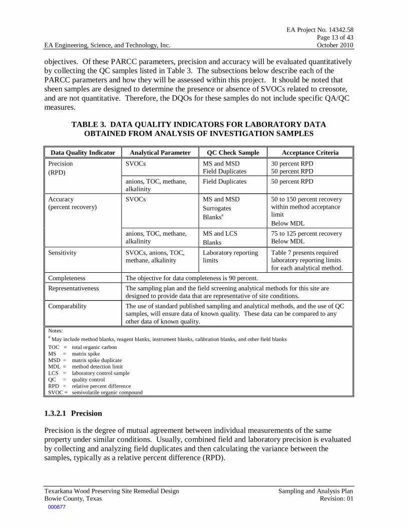
objectives. Of these PARCC parameters, precision and accuracy will be evaluated quantitatively by collecting the QC samples listed in Table 3. The subsections below describe each of the PARCC parameters and how they will be assessed within this project. It should be noted that sheen samples are designed to determine the presence or absence of SVOCs related to creosote, and are not quantitative. Therefore, the DQOs for these samples do not include specific QA/QC measures.
TABLE 3. DATA QUALITY INDICATORS FOR LABORATORY DATA OBTAINED FROM ANALYSIS OF INVESTIGATION SAMPLES
Data Quality Indicator Analytical Parameter QC Check Sample Acceptance Criteria Precision (RPD)
SVOCs MS and MSD Field Duplicates
30 percent RPD 50 percent RPD
anions, TOC, methane, alkalinity
Field Duplicates 50 percent RPD
Accuracy (percent recovery)
SVOCs MS and MSD Surrogates Blanksa
50 to 150 percent recovery within method acceptance limit Below MDL
anions, TOC, methane, alkalinity
MS and LCS Blanks
75 to 125 percent recovery Below MDL
Sensitivity SVOCs, anions, TOC, methane, alkalinity
Laboratory reporting limits
Table 7 presents required laboratory reporting limits for each analytical method.
Completeness The objective for data completeness is 90 percent. Representativeness The sampling plan and the field screening analytical methods for this site are
designed to provide data that are representative of site conditions. Comparability The use of standard published sampling and analytical methods, and the use of QC
samples, will ensure data of known quality. These data can be compared to any other data of known quality.
Notes: a May include method blanks, reagent blanks, instrument blanks, calibration blanks, and other field blanks TOC = total organic carbon MS = matrix spike MSD = matrix spike duplicate MDL = method detection limit LCS = laboratory control sample QC = quality control RPD = relative percent difference SVOC = semivolatile organic compound
1.3.2.1 Precision
Precision is the degree of mutual agreement between individual measurements of the same property under similar conditions. Usually, combined field and laboratory precision is evaluated by collecting and analyzing field duplicates and then calculating the variance between the samples, typically as a relative percent difference (RPD).
000877

EA Project No. 14342.58 Page 14 of 43 EA Engineering, Science, and Technology, Inc. October 2010
Texarkana Wood Preserving Site Remedial Design Sampling and Analysis Plan Bowie County, Texas Revision: 01
RPD is calculated as follows:
( ) 100%2BA
BARPD ×
+
−=
where A = First duplicate concentration. B = Second duplicate concentration. Field sampling precision is evaluated by analyzing field duplicate samples. For every 10 samples collected, 1 blind duplicate sample will be collected. Laboratory analytical precision is evaluated by analyzing laboratory duplicates or matrix spike (MS) and matrix spike duplicates (MSD). The results of the analysis of each laboratory duplicate or MS/MSD pair will be used to calculate the RPD as a measure of laboratory precision. 1.3.2.2 Accuracy
A program of sample spiking will be conducted to evaluate laboratory accuracy. This program includes analysis of the MS and MSD samples, laboratory control sample (LCS) or blank spikes, surrogate standards, and method blanks. MS and MSD samples will be prepared and analyzed at a frequency of 5 percent. LCS or blank spikes are also analyzed at a frequency of 5 percent. Surrogate standards, where available, are added to every sample analyzed for organic constituents. The results of the spiked samples are used to calculate the percent recovery for evaluating accuracy.
%100T
CSRecoveryPercent ×−
=
where S = Measured spike sample concentration. C = Sample concentration. T = True or actual concentration of the spike. 1.3.2.3 Representativeness
Representativeness expresses the degree to which sample data accurately and precisely represent the characteristics of a population, variations in a parameter at a sampling point, or an environmental condition that they are intended to represent. For this project, representative data will be obtained through careful selection of sampling locations and analytical parameters. Representative data will also be obtained through proper collection and handling of samples to avoid interference and minimize contamination. Representativeness of data will also be ensured through the consistent application of established field and laboratory procedures. Field blanks (if appropriate) and laboratory blank samples will
000878

EA Project No. 14342.58 Page 15 of 43 EA Engineering, Science, and Technology, Inc. October 2010
Texarkana Wood Preserving Site Remedial Design Sampling and Analysis Plan Bowie County, Texas Revision: 01
be evaluated for the presence of contaminants to aid in evaluating the representativeness of sample results. Data determined, by comparison with existing data, to be non-representative will be used only if accompanied by appropriate qualifiers and limits of uncertainty. 1.3.2.4 Completeness
Completeness is a measure of the percentage of project-specific data that are valid. Valid data are obtained when samples are collected and analyzed in accordance with QC procedures outlined in this SAP, and when none of the QC criteria that affect data usability are exceeded. When all data validation is completed, the percent completeness value will be calculated by dividing the number of useable sample results by the total number of sample results planned for this investigation. Completeness will also be evaluated as part of the data quality assessment process (EPA 2006c, 2006d). This evaluation will help determine whether any limitations are associated with the decisions to be made based on the data collected. 1.3.2.5 Comparability
Comparability expresses the confidence with which one data set can be compared with another. Comparability of data will be achieved by consistently following standard field and laboratory procedures and by using standard measurement units in reporting analytical data.
1.3.2.6 Detection and Quantitation Limits
The method detection limit (MDL) is the minimum concentration of an analyte that can be reliably distinguished from background noise for a specific analytical method. The quantitation limit represents the lowest concentration of an analyte that can be accurately and reproducibly quantified in a sample matrix. Contract-required quantitation limits (CRQLs) are contractually specified maximum quantitation limits for specific analytical methods and sample matrices, such as soil or water, and are typically several times the MDL to allow for matrix effects. CRQLs, which are established by EA in the scope of work for subcontract laboratories, are set to establish minimum criteria for laboratory performance; actual laboratory quantitation limits may be substantially lower. For this project, analytical methods have been selected so that the CRQL for each target analyte is below the applicable regulatory screening criteria, the Maximum Contaminant Levels (MCLs), wherever practical. For this project, samples results will be reported as estimated values if concentrations are less than CRQLs but greater than MDLs. The MDL for each analyte will be listed as the detection limit in the laboratory’s electronic data deliverable. 1.4 SPECIAL TRAINING AND CERTIFICATION
This section outlines the training and certification required to complete the activities described in this SAP and describes the requirements for the field team working onsite.
000879

EA Project No. 14342.58 Page 16 of 43 EA Engineering, Science, and Technology, Inc. October 2010
Texarkana Wood Preserving Site Remedial Design Sampling and Analysis Plan Bowie County, Texas Revision: 01
1.4.1 Health and Safety Training
EA field team personnel who work at hazardous waste project sites are required to meet the Occupational Safety and Health Administration (OSHA) training requirements defined in 29 Code of Federal Regulations (CFR) 1910.120(e). These requirements include: (1) 40 hours of formal offsite instruction, (2) a minimum of 3 days of actual onsite field experience under the supervision of a trained and experienced field supervisor, and (3) 8 hours of annual refresher training. Field personnel who directly supervise employees engaged in hazardous waste operations also receive at least 8 additional hours of specialized supervisor training.
Copies of the field team’s health and safety training records, including course completion certifications for the initial and refresher health and safety training and specialized supervisor training are maintained in project files.
Before work begins at a specific hazardous waste project site, EA personnel are required to undergo site-specific training that thoroughly covers the following areas:
• Names of personnel and alternates responsible for health and safety at a hazardous waste project site
• Health and safety hazards present onsite
• Selection of the appropriate personal protective equipment (PPE)
• Correct use of PPE
• Work practices to minimize risks from hazards
• Safe use of engineering controls and equipment onsite
• Medical surveillance requirements, including recognition of symptoms and signs that indicate overexposure to hazardous substances.
For more health and safety details, see EA’s site-specific HSP (EA 2010).
1.4.2 Subcontractor Training
Subcontractors who work on site will certify that their employees have been trained for work on hazardous waste project sites, except in select instances where the subcontractor is performing work of a limited and non-intrusive nature, such as mowing vegetation. Training will meet OSHA requirements defined in 29 CFR 1910.120(e). Before work begins at the project site, subcontractors will submit copies of the training certification for each employee to EA.
All employees of associate and professional services firms and technical services subcontractors will attend a safety briefing and complete the Safety Meeting Sign-Off Sheet before they conduct onsite work. This briefing is conducted by the EA health and safety officer or other qualified person.
000880

EA Project No. 14342.58 Page 17 of 43 EA Engineering, Science, and Technology, Inc. October 2010
Texarkana Wood Preserving Site Remedial Design Sampling and Analysis Plan Bowie County, Texas Revision: 01
Subcontractors are responsible for conducting their own safety briefings. EA personnel may audit these briefings.
1.5 DOCUMENTS AND RECORDS
The following sections discuss the requirements for documenting field activities and for preparing laboratory data packages. This section also describes reports that will be generated as a result of this project.
1.5.1 Field Documentation
Field personnel will use permanently bound field logbooks with sequentially numbered pages to record and document field activities and will follow Field Technical Procedures and Guidelines, standard operating procedure (SOP) 1.3 (Appendix A). The logbook will list the contract name and number; site name; and names of subcontractors, service client, and project manager. At a minimum, the following information will be recorded in the field logbook:
• Name and affiliation of all onsite personnel or visitors • Weather conditions during the field activity • Summary of daily activities and significant events • Notes of conversations with coordinating officials • References to other field logbooks or forms that contain specific information • Discussions of problems encountered and their resolution • Discussions of deviations from the SAP or other governing documents • Description of all photographs taken.
1.5.2 Laboratory Documentation
The following documentation will be required for full data validation, if applicable:
• Case narratives, which will describe all QC non-conformances that are encountered during the analysis of samples in addition to any corrective actions that are taken
– Statement of samples received – Description of any deviations from the specified analytical method – Explanations of data qualifiers that are applied to the data – Any other significant problems that were encountered during analysis.
• Tables that cross-reference field and laboratory sample numbers
• Chain-of-custody forms, which pertain to each sample delivery group or sample batch that is analyzed
• Laboratory reports, which must show traceability to the sample analyzed and must contain specified information
– Project identification
000881

EA Project No. 14342.58 Page 18 of 43 EA Engineering, Science, and Technology, Inc. October 2010
Texarkana Wood Preserving Site Remedial Design Sampling and Analysis Plan Bowie County, Texas Revision: 01
– Field sample number
– Laboratory sample number
– Dates and times of sample collection, receipt at the laboratory, preparation, and analysis
– Description of analytical method and reference citation
– Results of individual parameters, with mass units, and other confirmatory results, where appropriate
– Quantitation limits achieved
– Dilution or concentration factors.
• Data summary forms and QC summary forms showing analytical results, if applicable
– Samples – Surrogates – Blanks – Field QC samples – LCS – Initial and continuing calibrations – Other QC samples.
1.5.3 Reports Generated
A Data Validation Report and a Data Usability Summary for the Texarkana Site will be prepared at the conclusion of all the field work. The reports will include a summary of the results of the current investigations, field and sampling procedures for the soil and ground water investigation, ground water target analyte concentration and associated QC data, conclusions, and recommendations.
000882

EA Project No. 14342.58 Page 19 of 43 EA Engineering, Science, and Technology, Inc. October 2010
Texarkana Wood Preserving Site Remedial Design Sampling and Analysis Plan Bowie County, Texas Revision: 01
2. DATA GENERATION AND ACQUISITION
This section describes the requirements for the following:
• Sampling process design (Section 2.1)
• Sampling methods (Section 2.2)
• Sample handling and custody (Section 2.3)
• Analytical methods (Section 2.4)
• Quality control requirements (Section 2.5)
• Instrument and equipment testing, inspection, and maintenance requirements (Section 2.6)
• Instrument calibration and frequency (Section 2.7)
• Requirements for inspection and acceptance of supplies and consumables (Section 2.8)
• Data acquisition requirements (Section 2.9)
• Data management (Section 2.10).
2.1 SAMPLING PROCESS DESIGN
The primary objective of this investigation is to collect soil, ground water, surface water and lithologic data in order to: (1) determine the lateral extent of DNAPL and possibly sheen requiring S/S; (2) determine depth to the top of the clay layer separating the IWBZ from the SWBZ in areas requiring S/S; (3) perform full scale demonstration of S/S procedure on contaminated soil to confirm suitability of the remedy; (4) determine if there are indications that natural attenuation is occurring at the site; (5) determine if contamination exists in the IWBZ; and (6) determine whether contamination exists in surface water. It is anticipated that a single month-long mobilization and subsequent shorter mobilizations as necessary will be required.
Sampling methods will include direct-push soil sampling, augered (mixed and stabilized) soil sampling, low-flow ground water sampling, and surface water grab sampling. Sampling methods are described in Section 2.2.
2.1.1 Access Agreements
The proposed sampling locations are located on private property or utility right-of-ways. EA understands that EPA has or can, in a timely manner, obtain valid access agreements for all properties on which sampling will occur.
000883

EA Project No. 14342.58 Page 20 of 43 EA Engineering, Science, and Technology, Inc. October 2010
Texarkana Wood Preserving Site Remedial Design Sampling and Analysis Plan Bowie County, Texas Revision: 01
2.1.2 Underground Utilities Survey
A one-call notification center (Texas 811) will be contacted to provide an underground utilities survey, to clear all soil boring locations before any intrusive activities begin. The survey will include water distribution piping, telecommunications lines, storm sewer lines, sanitary sewer lines, industrial wastewater lines, gas lines, fire water lines, fuel product lines, and electrical lines.
2.1.3 Surveying
The new monitoring wells and direct-push points will be surveyed using a GeoXT™ Global Positioning System (GPS) from Trimble. The following GPS data attributes for each well position will be logged:
• Latitude • Longitude • Collector Name • Collection Method • Datum • Maximum Positional Dilution of Precision • GPS Date and Time • Total Positions Collected (at each well location).
Positional data obtained by the GeoExplorer III will be differentially corrected to remove certain types of error.
Elevations for each monitoring well top of casing will be measured and referenced to a relative benchmark using an auto-balancing laser surveyor.
2.2 SAMPLING METHODS
This section describes the procedures for sample collection, including sampling methods and equipment, sample preservation requirements, decontamination procedures, and management of investigation-derived waste (IDW). Table 4 lists the SOPs that will be implemented during this field program. SOPs and additional operating procedures for sampling equipment are provided in Appendix A.
Sample collection and handling procedures for samples that will be analyzed using CLP will follow CLP protocols as required in the field samplers guide provided in Appendix B.
TABLE 4. STANDARD OPERATING PROCEDURES
SOP Number and Title General Requirements
001 Sample Labels 002 Chain-of-Custody Form 004 Sample Packing and Shipping
000884

EA Project No. 14342.58 Page 21 of 43 EA Engineering, Science, and Technology, Inc. October 2010
Texarkana Wood Preserving Site Remedial Design Sampling and Analysis Plan Bowie County, Texas Revision: 01
SOP Number and Title 016 Surface Water, Groundwater, and Soil/Sediment Field Logbooks 039 Sample Preservation and Container Requirements
Drilling, Trenching and Sampling Soils and Rocks 025 Soil Sampling 019 Monitoring Well Installation Water Sampling
048 Low-Flow Sampling 005 Field Decontamination 007 Surface Water Sampling Bio-Flo – DNA Sampling Protocol Bio‐Trap – Stable Isotope Probing protocol Hach Method 8146 for Ferrous Iron
Air Monitoring 024 Photoionization Detector (Microtip HL-200)
2.2.1 Sampling
Direct-push methodology will be used to collect soil samples from S/S areas. A hollow-stem auger drilling rig will be used to install monitoring wells. Ten monitoring wells in the SWBZ and eight monitoring wells in the IWBZ will be installed as part of this field program at the Site.
The proposed locations for the new monitoring wells are presented on Figure 3. Direct-push methodology will also be used to advance boreholes to determine the extent of DNAPL and sheen, and to determine the depth to the top of the clay layer separating the IWBZ and the SWBZ. Following completion of the S/S demonstration, soil samples will be collected and analyzed for UCS, permeability, and leachability to evaluate suitability of the remedy. Data collection procedures are explained in the following sections.
2.2.1.1 Monitoring Well Installation
Monitoring well construction will be performed by a Texas-licensed well driller under the supervision of a Texas-licensed Geoscientist. Well construction methods are described in SOP No. 019. After the estimated top of the saturated zone is identified by the site geologist, the well bore will be deepened to target depth. The following general specifications will be followed:
1. Well materials will be 4-inch Schedule 40 polyvinyl chloride (PVC) with machine-cut slots and flush-thread joints. Screen and blank casing will be delivered to the Site in sealed packaging.
2. The monitoring wells will span the water table in the SWBZ, screened throughout the water table. Intermediate wells will be advanced far enough into the aquifer, so that each well can be constructed with 20 feet of screen in the IWBZ.
3. Monitoring well screens will have 0.010-inch (e.g., 10-slot) machine-cut slots and 20-40 mesh silica sand filter pack.
000885

EA Project No. 14342.58 Page 22 of 43 EA Engineering, Science, and Technology, Inc. October 2010
Texarkana Wood Preserving Site Remedial Design Sampling and Analysis Plan Bowie County, Texas Revision: 01
PVC casing and screen will be installed in the hollow-stem augers, and the well will be constructed. As the auger flights are withdrawn, sand pack will be placed in the annulus to a point that is about 2 feet above the top of the screen. A 2-foot-thick hydrated sodium bentonite seal will be placed on top of the sand pack, and the remainder of the annulus will be grouted with cement-bentonite grout. The cement-bentonite grout will be placed into the annulus for the remaining 1.5 feet or so.
All of the new wells will have stickup completions (i.e., above grade). All wells will be installed and completed following the State of Texas completion guidelines.
Surface Completions
The monitoring wells will be developed following the correct completion of each well. The wells will be allowed to set 24 hours prior to well development. All down-hole equipment including surge blocks and/or pumps will be decontaminated before and after use. All water derived from decontamination will be collected and temporarily stored at the staging area for characterization.
Well Development
All drilling equipment should be steam cleaned or cleaned using high-pressure water at the completion of the project to ensure that no contamination is transported from the sampling site. Special attention should be given to the thread section of the casings and to the drill rods. Cleaned equipment should not be handled with soiled gloves. Decontamination of the equipment will follow general practices listed in SOP No. 005 (Appendix A). All water derived from decontamination will be collected and temporarily stored at the staging area for characterization. The work area will be screened using a photoionization detector, and any readings will be documented.
2.2.1.2 Soil Borings
Direct push cores will be advanced to the bottom of the creosote layer on the bottom of the aquifer, and the thickness of the creosote will be determined visually. Areas with at least 10 inches of creosote will be identified as areas of “high mass” creosote. Borings will be installed using standard step-out procedures to verify and further delineate the extent of the high mass creosote. The extent of high mass creosote shown in the Focused FS Report (EA 2009) is based on data points from a 100-foot grid. During this field event, the limits of the high mass creosote will be refined by collecting additional information from points between the nodes of the original grid, down to spacings as little as 25 feet apart. Where appropriate and when time permits, the geologist in the field may advance borings at locations off the grid lines to verify or disprove previous interpolations and assumptions related to the extent of high mass DNAPL.
Delineation of DNAPL
All direct push cores will be monitored for soil with a noticeable layer of sheen. Once field samplers determine that a substantial quantity of sheen is present, a 16 in2 hydrophobic
Observation of Sheen
000886
EA Project No. 14342.58 Page 23 of 43 EA Engineering, Science, and Technology, Inc. October 2010
Texarkana Wood Preserving Site Remedial Design Sampling and Analysis Plan Bowie County, Texas Revision: 01
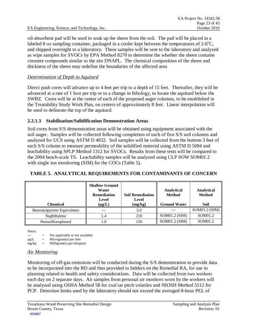
oil-absorbent pad will be used to soak up the sheen from the soil. The pad will be placed in a labeled 8 oz sampling container, packaged in a cooler kept between the temperatures of 2-6oC, and shipped overnight to a laboratory. These samples will be sent to the laboratory and analyzed as wipe samples for SVOCs by EPA Method 8270 to determine the whether the sheen contains creosote compounds similar to the site DNAPL. The chemical composition of the sheen and thickness of the sheen may redefine the boundaries of the affected area
Direct push cores will advance up to 4 feet per trip to a depth of 15 feet. Thereafter, they will be advanced at a rate of 1 foot per trip or to a change in lithology, to locate the aquitard below the SWBZ. Cores will be at the center of each of the proposed auger columns, to be established in the Treatability Study Work Plan, on centers of approximately 8 feet. Linear interpolation will be used to delineate the top of the aquitard.
Determination of Depth to Aquitard
2.2.1.3 Stabilization/Solidification Demonstration Areas Soil cores from S/S demonstration areas will be obtained using equipment associated with the soil auger. Samples will be collected following completion of each of five S/S soil columns and analyzed for UCS using ASTM D 4832. Soil samples will be collected from the bottom 3 feet of each S/S column to measure permeability of the solidified material using ASTM D 5084 and leachability using SPLP Method 1312 for SVOCs. Results from these tests will be compared to the 2004 bench-scale TS. Leachability samples will be analyzed using CLP SOW SOM01.2 with single ion monitoring (SIM) for the COCs (Table 5).
TABLE 5. ANALYTICAL REQUIREMENTS FOR CONTAMINANTS OF CONCERN
Chemical
Shallow Ground Water
Remediation Level (µg/L)
Soil Remediation Level
(mg/kg)
Analytical Method
Ground Water
Analytical Method
Soil
Benzo(a)pyrene Equivalents --- 3.0 --- SOM01.2 (SIM) Naphthalene 1.4 210 SOM01.2 (SIM) SOM01.2
Pentachlorophenol 1.0 150 SOM01.2 (SIM) SOM01.2
Notes: --- = Not applicable or not available µg/L = Microgram(s) per liter mg/kg = Milligram(s) per kilogram
Monitoring of off-gas emissions will be conducted during the S/S demonstration to provide data to be incorporated into the RD and thus provided to bidders on the Remedial RA, for use in planning related to health and safety considerations. Data will be collected from two workers each day on 2 separate days. Air samples from personal air monitors worn by the workers will be analyzed using OSHA Method 58 for coal tar pitch volatiles and NIOSH Method 5512 for PCP. Detection limits used by the laboratory should not exceed the averaged 8-hour PEL of
Air Monitoring
000887

EA Project No. 14342.58 Page 24 of 43 EA Engineering, Science, and Technology, Inc. October 2010
Texarkana Wood Preserving Site Remedial Design Sampling and Analysis Plan Bowie County, Texas Revision: 01
0.2 mg/m3 for coal tar pitch volatiles and 0.5 mg/m3 for PCP. In addition, worker safety will also be monitored with real time indicators as detailed in the RD HSP.
2.2.1.4 Decontamination of Drilling Equipment
All drilling equipment (including the soil auger) will be steam cleaned or cleaned using high-pressure water at the completion of the project to ensure that no contamination is transported from the sampling site. Special attention will be given to the thread section of the casings and to the drill rods. Cleaned equipment will not be handled with soiled gloves. Decontamination of the equipment will follow general practices listed in SOP No. 005 (Appendix A). All water derived from decontamination will be collected and temporarily stored at the staging area for characterization. The work area will be screened using a photoionization detector, and any readings will be documented.
2.2.1.5 Ground Water Sampling The EA field team will collect ground water samples from each newly installed monitoring well and a select number of existing wells. Well completion logs will be reviewed prior to ground water sampling. Each monitoring well will be gauged prior to purging to document the depth to water from top of casing and for pump setting. The EA field team will collect ground water samples from the monitoring wells using low-flow (i.e., micropurge using ground water sampling equipment) sampling techniques, as specified in SOP No. 048 (Appendix A). Low-flow sampling requires that minimal drawdown is maintained throughout purging of the well in order to ensure that the water being purged is in fact entering the pump from the formation, and not as a result of lowering water levels within the well. Water level measurements should be collected periodically to confirm that drawdown is not occurring. Table 6 presents the field water quality parameters to be collected throughout purging and logged for all wells on ground water data sampling sheets.
TABLE 6. WATER QUALITY PARAMETERS TO BE MONITORED
Parameter Field-based Method
Dissolved oxygen YSI 3800 (or equivalent)
pH YSI 3800 (or equivalent)
Specific conductance YSI 3800 (or equivalent)
Water temperature YSI 3800 (or equivalent)
Oxidation-reduction potential
YSI 3800 (or equivalent)
Turbidity YSI 3800 (or equivalent)
Ground water will continue to be purged until measurements of temperature and conductivity have stabilized to within 10 percent, and pH has stabilized to within 0.1 units. Other field parameters will be collected to evaluate natural attenuation parameters, including ORP and DO, but will not be used as stabilizing criteria. Sampling methods and equipment were selected to meet project objectives.
000888

EA Project No. 14342.58 Page 25 of 43 EA Engineering, Science, and Technology, Inc. October 2010
Texarkana Wood Preserving Site Remedial Design Sampling and Analysis Plan Bowie County, Texas Revision: 01
Ground water samples will be collected and analyzed to evaluate whether contamination is present in the IWBZ and to evaluate natural attenuation indicators in the SWBZ. Samples from both water bearing zones will be analyzed for SVOCs. The SWBZ samples also will include analyses for selected inorganics (i.e., nitrate, sulfate, and chloride), total organic carbon (TOC), methane, alkalinity, and microbial identification. In addition, a SIP test will be conducted in the SWBZ to identify specific contaminant degradation. Table 7 specifies the required analytical methods and reporting limits for each analysis. Table 8 specifies sample volume, container type, preservation technique, and holding time for each analysis that is to be conducted on the ground water samples collected. Required containers, preservation techniques, and holding times for field QC samples, such as field duplicates, field blanks, trip blanks, and MS/MSD samples will be the same as for field samples, but will require additional volumes as described Table 9 in Section 2.5.
TABLE 7. METHODS AND REPORTING REQUIREMENTS FOR NATURAL ATTENUATION INDICATORS IN SHALLOW GROUND WATER
Analyte
Minimum Limit of
Quantification Units
Analytical Method/Field Instrument1 Notes
Field Measurements
Dissolved Oxygen 0.2 mg/L YSI 3800 (or equivalent) ORP indicator ORP + or - 300 mV YSI 3800 (or equivalent) ORP indicator
Ferrous iron 0.5 mg/L Hach Method 8146 ORP indicator Temperature 0 o C YSI 3800 (or equivalent) Reaction rate indicator
pH 0.1 units YSI 3800 (or equivalent) Reaction rate indicator
Non-CLP Laboratory Nitrate 0.1 mg/L EPA 300.0 ORP indicator
Total organic carbon 0.1 mg/L EPA 415.1 or 9060 Carbon and energy source Sulfate 5 mg/L EPA 300.0 ORP indicator
Methane 0.5 mg/L Gas chromatograph ORP indicator Alkalinity 50 mg/L SM 2320 B Biodegradation indicator Chloride 1 mg/L EPA 300.0 Biodegradation indicator
CLP Laboratory Pentachlorophenol 0.0002 mg/L CLP SOM01.2 Material released
2,4,5-Trichlorophenol 0.005 mg/L CLP SOM01.2 Possible daughter product 2,4,6-Trichlorophenol 0.005 mg/L CLP SOM01.2 Possible daughter product 2,4-Dichlorophenol 0.005 mg/L CLP SOM01.2 Daughter product
2-Chlorophenol 0.005 mg/L CLP SOM01.2 Daughter product
Microbial Identification
Pentachlorophenol (aerobic) Goal = 100 cells CENSUS qPCR Reporting limit is a goal, not a requirement
Pentachlorophenol (anaerobic) Goal = 100 cells CENSUS qPCR
Reporting limit is a goal, not a requirement
Dehalococcoides spp. Goal = 100 cells CENSUS qPCR Reporting limit is a goal, not a requirement
000889

EA Project No. 14342.58 Page 26 of 43 EA Engineering, Science, and Technology, Inc. October 2010
Texarkana Wood Preserving Site Remedial Design Sampling and Analysis Plan Bowie County, Texas Revision: 01
Analyte
Minimum Limit of
Quantification Units
Analytical Method/Field Instrument1 Notes
Naphthalene (aerobic) Goal = 100 cells CENSUS qPCR Reporting limit is a goal, not a requirement
Notes: 1 Samples from the IWBZ will be analyzed for SVOCs using CLP SOW SOM01.2 only. CLP = Contract Laboratory Program mg/L = milligram per liter mV = millivolt ORP = oxidation/reduction potential qPCR = quantitative polymerase chain reaction SVOC = semivolatile organic compound
TABLE 8. REQUIRED SAMPLE VOLUME, CONTAINERS, PRESERVATIVES, AND HOLDING TIMES
Parameter Method Volume and Container Preservatives Holding Time 1 SVOCs CLP SOM01.2 Two 1-L amber glass bottles store at 4° C in
darkness Extract in 14 days
Anions EPA 300.0 One 1-L high-density polyethylene bottles with polyethylene cap store at 4° C
Nitrate = 48 hours;
sulfate/chloride = 28 days
Methane RSK-175 Two 40-ml glass vials with Teflon-lined septum
HCl to pH <2 and store at 4° C 14 days
Alkalinity SM 2320 B 100-ml high density polyethylene bottle with polyethylene cap store at 4° C 14 days
Microbial Identification
CENSUS qPCR Filter provided by the laboratory store at 4° C 48 hours
Stable Isotope Probing
GC-IRMS Bio-trap provided by the laboratory store at 4° C 48 hours
Notes:
1 Holding time is measured from the time of sample collection to the time of sample extraction and analysis.
GC-IRMS = gas chromatography-isotope ratio monitoring mass spectrometry HCl = hydrochloric acid L = liter ml = milliliter qPCR = quantitative polymerase chain reaction SVOC = semivolatile organic compound 2.2.1.4 Surface Water Sampling Surface water samples will be grab samples collected from the approximate middle of the flow of Days Creek or from ponded areas if conditions are dry. Care will be taken to avoid collecting stream sediments, surface scum or sheens, and/or turbid water. If water is not flowing, samples will be collected near the bank to avoid disturbing the sediment by wading in the water. Sampling will begin at the furthest downstream location and proceed upstream. Samples are to be analyzed for SVOCs; Table 8 specifies required sample volume, container type, preservation
000890

EA Project No. 14342.58 Page 27 of 43 EA Engineering, Science, and Technology, Inc. October 2010
Texarkana Wood Preserving Site Remedial Design Sampling and Analysis Plan Bowie County, Texas Revision: 01
technique and holding time. Approximate locations are indicated on Figure 4, but locations may be adjusted in the field for reasons such as facilitation of access or incorporation of water which has sheen on its surface.
2.2.1.5 Decontamination All equipment utilized during the various tasks under this SAP will decontaminated prior to and after use. A decontamination pad with water supply will be set up at a designated location. For decontamination of drilling equipment, a sump pump will be utilized to drum all water and prevent offsite runoff.
2.2.1.6 Management of Investigation-Derived Waste All decontamination and purge water generated during the various phases of work will be suitably disposed. Any necessary IDW characterization samples will be analyzed using an EA-subcontracted laboratory.
2.3 SAMPLE HANDLING AND CUSTODY
Each sample collected by the EA field team will be traceable from the point of collection through analysis and final disposition to ensure sample integrity. Sample integrity helps to ensure the legal defensibility of the analytical data and subsequent conclusions. Ground water sample handling will follow CLP protocols as required in EPA’s Contract Laboratory Program Guidance for Field Samplers (EPA 2007) (Appendix B).
EA will use EPA’s data management system, known as “Forms II Lite,” to produce all chain-of-custody records in the field. Applicable copies of generated Forms II Lite files will be delivered to EPA data management personnel as required by CLP protocols.
For samples that will be analyzed in the field, the following general guidelines should be followed as discussed in the sections below.
2.3.1 Sample Documentation
Documentation during sampling is essential to ensure proper sample identification. EA personnel will adhere to the following general guidelines for maintaining field documentation:
• Documentation will be completed in permanent ink.
• All entries will be legible.
• Errors will be corrected by crossing out with a single line and then dating and initialing the lineout.
• Any serialized documents will be maintained at EA and referenced in the site logbook.
• Unused portions of pages will be crossed out, and each page will be signed and dated.
000891

EA Project No. 14342.58 Page 28 of 43 EA Engineering, Science, and Technology, Inc. October 2010
Texarkana Wood Preserving Site Remedial Design Sampling and Analysis Plan Bowie County, Texas Revision: 01
The EA field team leader is responsible for ensuring that sampling activities are properly documented.
2.3.1.1 Sample Labels
A sample label will be affixed to each sample container. The label will be completed with the following information written in indelible ink:
• Project name and location • Sample identification number • Date and time of sample collection • Sample collector’s initials • Analysis required.
2.3.1.2 Chain-of-Custody
EA will use standard sample custody procedures to maintain and document sample integrity during collection, transportation, storage, and analysis. A sample will be considered to be in custody if one of the following statements applies:
• It is in a person’s physical possession or view.
• It is in a secure area with restricted access.
• It is placed in a container and secured with an official seal such that the sample cannot be reached without breaking the seal.
Chain-of-custody procedures provide an accurate written record that traces the possession of individual samples from the time of collection in the field to the time of acceptance at the laboratory. The chain-of-custody record will be used to document all samples collected and the analysis requested. Information that the field personnel will record on the chain-of-custody record includes:
• Project name and number
• Sampling location
• Name and signature of sampler
• Destination of samples (laboratory name)
• Sample identification number
• Date and time of collection
• Analysis requested
000892

EA Project No. 14342.58 Page 29 of 43 EA Engineering, Science, and Technology, Inc. October 2010
Texarkana Wood Preserving Site Remedial Design Sampling and Analysis Plan Bowie County, Texas Revision: 01
• Signatures of individuals involved in custody transfer, including the date and time of transfer
• Airbill number (if applicable)
• Project contact and phone number.
Unused lines on the chain-of-custody record will be crossed out. Field personnel will sign chain-of-custody records that are initiated in the field, and the airbill number will be recorded. The record will be placed in a waterproof plastic bag and taped to the inside of the shipping container used to transport the samples. Signed airbills will serve as evidence of custody transfer between field personnel and the courier, and between the courier and the laboratory. Copies of the chain-of-custody record and the airbill will be retained and filed by field personnel before the containers are shipped.
The following procedures will be implemented when samples collected during this project are shipped to analytical laboratories (with shipping considerations applicable to laboratories other than geotechnical laboratories):
• The shipping box will be filled with bubble wrap, sample bottles, and packing material. Sufficient packing material will be used to prevent sample containers from breaking during shipment.
• The chain-of-custody records will be placed inside a plastic bag. The bag will be sealed
and taped to the inside of the cooler lid. The airbill, if required, will be filled out before the samples are handed over to the carrier. The laboratory will be notified if the sampler suspects that the sample contains any substance that would require laboratory personnel to take safety precautions.
• The shipping box will be closed and taped shut with strapping tape around both ends. • Signed and dated custody seals will be placed on the front and side of each shipping box.
Wide clear tape will be placed over the seals to prevent accidental breakage. • The chain-of-custody record will be transported within the taped sealed shipping box.
When the shipping box is received at the analytical laboratory, laboratory personnel will open the shipping box and sign the chain-of-custody record to document transfer of samples.
Sample handling procedures for geotechnical samples will be in accordance with the relevant ASTM methods. 2.4 ANALYTICAL METHODS
The source of analytical services to be provided will be determined in part by DQOs and the intended use of the resulting data. EA will use EPA-approved methods for laboratory analyses of the ground water and surface water samples. Ground water samples from all wells and
000893

EA Project No. 14342.58 Page 30 of 43 EA Engineering, Science, and Technology, Inc. October 2010
Texarkana Wood Preserving Site Remedial Design Sampling and Analysis Plan Bowie County, Texas Revision: 01
surface water samples will be analyzed for SVOCs; ground water samples from selected wells in the SWBZ also will be analyzed for the other constituents and parameters indicated on Table 7.
EA will follow the analytical services request procedures that are outlined EA’s Analytical Services Delivery Plan (EA 2005). If an analytical system fails, the QA officer will be notified, and corrective action will be taken. In general, corrective actions will include stopping the analysis, examining instrument performance and sample preparation information, and determining the need to re-prepare and reanalyze the samples.
2.4.1 Field Analytical Methods
Water quality parameters, including pH, temperature, specific conductivity, ORP, DO, and turbidity will be monitored using an YSI 3800 (or equivalent) meter during the collection of ground water samples (Table 7). Additionally, ground water samples will be analyzed for ferrous iron using Hach Method 8146 (Appendix A). The field team will follow manufacturer recommended procedures for operating field equipment.
2.4.2 Laboratory Analytical Methods
Fixed laboratory analyses will be conducted by the EPA Region 6 Laboratory, a designated CLP laboratory, or a subcontract non-CLP laboratory as indicated in Table 7. All samples submitted to the analytical laboratory will be analyzed for SVOCs using CLP SOW SOM01.2 or SOM01.2 (SIM), anions (i.e., nitrate, sulfate, and chloride) using EPA 300.0, methane by gas chromatography (GC), alkalinity using SM 2320B, microbial identification using CENSUS qPCR, and stable isotope analysis using GC-isotope ratio monitoring mass spectrometry (IRMS). Modifications to analytical method that may be required to handle atypical matrices or to achieve low quantitation limits are presented in this section. Decisions regarding the use and type of method modifications will be made during the procurement of laboratories, as different laboratories have equipment and SOPs that produce varying quantitation limits.
The EPA quick reference fact sheet which lists the CRQLs for CLP SOW SOM01.2 is presented in Appendix C.
2.5 QUALITY CONTROL REQUIREMENTS
Various field and laboratory QC samples and measurements will be used to verify that analytical data meet the QA objectives. Field QC samples and measurements will be collected to assess the influence of sampling activities and measurements on data quality. Similarly, laboratory QC samples will be used to assess how the laboratory’s analytical program influences data quality. This section describes the QC samples that are to be analyzed during the Texarkana Site sampling activities for (1) each field and laboratory environmental measurement method, and (2) each sample matrix type. Table 9 presents the frequency of QC samples to be collected at the site.
000894

EA Project No. 14342.58 Page 31 of 43 EA Engineering, Science, and Technology, Inc. October 2010
Texarkana Wood Preserving Site Remedial Design Sampling and Analysis Plan Bowie County, Texas Revision: 01
TABLE 9. FREQUENCY OF FIELD QUALITY CONTROL SAMPLES
Field Quality Control Sample Frequency for Aqueous Matrix 1
Field blank 1 per day if site conditions render this sample necessary Field duplicate 1 per 10 samples (SVOCs) Equipment rinsate blank 1 per non-dedicated equipment type per day or 1 per
20 samples Matrix spike/matrix spike duplicate 2 (organics only)
1 per 20 samples
Matrix spike/matrix duplicate
(inorganics only) 1 per 20 samples
Temperature blank 1 per cooler Notes: 1 The quality control sample collection frequency applies to samples collected for field and laboratory analyses. 2 Matrix spike, matrix spike duplicate, and matrix duplicate analyses are technically not field quality control samples; however,
they generally require that the field personnel collect additional volume of sample, and are therefore included on this table for easy reference.
2.5.1 Field Quality Control Requirements
Field QC samples will be collected and analyzed to assess the quality of data that are generated by sampling activities. These samples will include laboratory QC samples collected in the field, field duplicates, equipment rinsates, MS/MSDs, and temperature blanks. QC samples collected in the field for fixed-laboratory analysis are presented in Table 9.
Contamination can be introduced from many external sources during collection of field samples. Field blanks will be collected based on field conditions—that is, if either winds or construction that create dust are encountered during sampling.
Field duplicates are independent samples that are collected as close as possible, in space and time, to the original investigative sample. Field duplicates can measure the influence of sampling and field procedures on the precision of an environmental measurement. They can also provide information on the heterogeneity of a sampling location. Field duplicates will be collected at a frequency of one for every 10 aqueous samples, as listed in Table 9. Immediately following collection of the original sample, the field duplicates are collected using the same collection method.
Equipment rinsate blanks are collected when non-dedicated or non-disposable sampling equipment is used to collect samples and put the samples into containers. These blanks assess the cleanliness of the sampling equipment and the effectiveness of equipment decontamination. Equipment rinsate blanks are collected by pouring analyte-free water over the decontaminated surfaces of sampling equipment that contacts sampling media. Equipment rinsate blanks are collected after sampling equipment has been decontaminated, but before the equipment is reused for sampling. If non-dedicated or non-disposable equipment is used, equipment rinsate blanks will be collected at a frequency as listed in Table 9.
MS and MSD samples are laboratory QC samples that are collected for organic methods. MS and laboratory duplicate samples are typically collected for analysis of inorganics. For aqueous
000895

EA Project No. 14342.58 Page 32 of 43 EA Engineering, Science, and Technology, Inc. October 2010
Texarkana Wood Preserving Site Remedial Design Sampling and Analysis Plan Bowie County, Texas Revision: 01
samples, MS/MSDs require double or triple the normal sample volume, depending on analytical laboratory specifications. Each MS and laboratory duplicate sample is one sample, usually collected from one location at double the normal sample volume. In the laboratory, MS/MSDs and MSs are split and spiked with known amounts of analytes. Analytical results for MS/MSDs and MSs and laboratory duplicate samples are used to measure the precision and accuracy of the laboratory’s organic and inorganic analytical programs, respectively. Each of these QC samples will be collected and analyzed at a frequency of one for every 20 investigative samples for CLP laboratories or subcontract non-CLP laboratories.
Temperature blanks are containers of deionized or distilled water that are placed in each cooler shipped to the laboratory. Their purpose is to provide a container to test the temperature of the samples in the respective cooler.
2.5.2 Laboratory Quality Control Requirements
All laboratories that perform analytical work under this project must adhere to a QA program that is used to monitor and control all laboratory QC activities. Each laboratory must have a written QA manual that describes the QA program in detail. The laboratory QA manager is responsible for ensuring that all laboratory internal QC checks are conducted in accordance with EPA methods and protocols, the laboratory's QA manual, and the requirements of this SAP.
Many of the laboratory QC procedures and requirements are described in EPA-approved analytical methods, laboratory method SOPs, and method guidance documents.
The EPA methods specify the preparation and analysis of QC samples, and may include, but are not limited to, the following types: (1) LCS, (2) method blanks, (3) MS and MSD samples, (4) surrogate spikes, and (5) standard reference materials or independent check standards. The following subsections discuss the QC checks that will be required for this project.
2.5.2.1 Laboratory Control Sample
LCSs are thoroughly characterized, laboratory-generated samples that are used to monitor the laboratory’s day-to-day performance of analytical methods. The results of LCS analyses are compared to well defined laboratory control limits to determine whether the laboratory system is in control for the particular method. If the system is not in control, corrective action will be implemented. Appropriate corrective actions will include (1) stopping the analysis, (2) examining instrument performance or sample preparation and analysis information, and (3) determining whether samples should be re-prepared or reanalyzed.
2.5.2.2 Method Blanks
Method blanks, which are also known as preparation blanks, are analyzed to assess the level of background interference or contamination in the analytical system and the level that may lead to elevated concentration levels or false-positive data. Method blanks will be required for all laboratory analyses and will be prepared and analyzed at a frequency of one method blank per every 20 samples or one method blank per batch, if the batches consist of fewer than 20 samples.
000896

EA Project No. 14342.58 Page 33 of 43 EA Engineering, Science, and Technology, Inc. October 2010
Texarkana Wood Preserving Site Remedial Design Sampling and Analysis Plan Bowie County, Texas Revision: 01
A method blank consists of reagents that are specific to the analytical method and are carried through every aspect of the analytical procedure, including sample preparation, cleanup, and analysis. The results of the method blank analysis will be evaluated in conjunction with other QC information to determine the acceptability of the data generated for that batch of samples. Ideally, the concentration of a target analyte in the method blank will be below the reporting limit for that analyte. For some common laboratory contaminants, a higher concentration may be allowed.
If the method blank for any analysis is beyond control limits, the source of contamination must be investigated, and appropriate corrective action must be taken and documented. This investigation includes an evaluation of the data to determine the extent of the contamination and its effect on sampling results. If a method blank is within control limits, but analysis indicates a concentration of analytes that is above the reporting limit, then an investigation should be conducted to determine whether any corrective action could eliminate an ongoing source of target analytes.
For organic and inorganic analyses, the concentration of target analytes in the method blank must be below the reporting limit for that analyte for the blank to be considered acceptable. An exception may be made for common laboratory contaminants (e.g., methylene chloride, acetone, 2-butanone, and phthalate esters) that may be present in the blank at up to five times the reporting limit. These compounds are frequently detected at low levels in method blanks from materials that are used to collect, prepare, and analyze samples for organic parameters.
2.5.2.3 Matrix Spikes and Matrix Spike Duplicates
MSs and MSDs are aliquots of an environmental sample to which known concentrations of target analytes and compounds have been added. The MS is used to evaluate the effect of the sample matrix on the accuracy of the analysis. If there are many target analytes, they will be divided into two to three spike standard solutions. Each spike standard solution will be used alternately. The MS, in addition to an unspiked aliquot, will be taken through the entire analytical procedure, and the recovery of the analytes will be calculated. Results will be expressed in terms of percent recoveries and RPD. The percent recoveries of the target analytes and compounds are calculated and used to determine the effects of the matrix on the precision and accuracy of the method. The RPD between the MS and MSD results is used to evaluate method precision.
The MS/MSD is divided into three separate aliquots, two of which are spiked with known concentrations of target analytes. The two spiked aliquots, in addition to an unspiked sample aliquot, are analyzed separately, and the results are compared to determine the effects of the matrix on the precision and accuracy of the analysis. Results will be expressed as RPD and percent recovery and compared to control limits that have been established for each analyte. If results fall outside control limits, corrective action will be performed.
2.5.2.4 Surrogate Spikes
Surrogates are organic compounds that are similar to the analytes of interest in chemical properties but are not normally found in environmental samples. Surrogates are added to field and QC samples, before the samples are extracted, to assess the efficacy of the extraction
000897

EA Project No. 14342.58 Page 34 of 43 EA Engineering, Science, and Technology, Inc. October 2010
Texarkana Wood Preserving Site Remedial Design Sampling and Analysis Plan Bowie County, Texas Revision: 01
procedure and to assess the bias that is introduced by the sample matrix. Results are reported in terms of percent recovery. Individual analytical methods may require sample reanalysis based on surrogate criteria.
The laboratory will use surrogate recoveries mainly to assess matrix effects on sample analysis. Obvious problems with sample preparation and analysis (e.g., evaporation to dryness or a leaking septum) that can lead to poor surrogate spike recoveries must be eliminated before low surrogate recoveries can be attributed to matrix effects.
2.5.3 Common Data Quality Indicators
This section describes how QA objectives for precision, accuracy, completeness, and sensitivity are measured, calculated, and reported.
2.5.3.1 Precision
Precision of many analyses is assessed by comparing analytical results of MS and MSD sample pairs for organic analyses, field duplicate samples, laboratory duplicate samples, and field replicate measurements. If precision is calculated from two measurements, it is normally measured as RPD. If precision is calculated from three or more replicates, relative standard deviation is calculated.
2.5.3.2 Accuracy
The accuracy of many analytical methods is assessed by using the results of MS and MSD samples for organic analyses, MS samples for inorganic analyses, surrogate spike samples, LCSs, standard reference materials, independent check standards, and measurements of instrument responses against zero and span gases.
For measurements in which spikes are used, percent recovery will be calculated.
2.5.3.3 Completeness
Completeness is a measure of the percentage of project-specific data that are valid. Valid data are obtained when samples are collected and analyzed in accordance with QC procedures outlined in this SAP, and when none of the QC criteria that affect data usability are exceeded.
When all data validation is completed, the percent completeness value will be calculated by dividing the number of useable results by the total number of sample results planned for this investigation.
Completeness will also be evaluated as part of the data quality assessment process (EPA 2000). This evaluation will help determine whether any limitations are associated with the decisions to be made based on the data collected.
000898

EA Project No. 14342.58 Page 35 of 43 EA Engineering, Science, and Technology, Inc. October 2010
Texarkana Wood Preserving Site Remedial Design Sampling and Analysis Plan Bowie County, Texas Revision: 01
2.5.3.4 Sensitivity
The achievement of MDLs depends on instrument sensitivity and matrix effects. Therefore, it is important to monitor the instrument sensitivity to ensure data quality and to ensure that analyses meet the QA objectives that have been established for sensitivity (Section 1.3.2).
2.6 INSTRUMENT AND EQUIPMENT TESTING, INSPECTION, AND MAINTENANCE REQUIREMENTS
This section outlines testing, inspection, and maintenance procedures for field equipment and instruments and for laboratory instruments.
2.6.1 General Requirements
Testing, inspection, and maintenance methods and frequency will be based on (1) the type of instrument; (2) the instrument’s stability characteristics; (3) the required accuracy, sensitivity, and precision of the instrument; (4) the instrument’s intended use, considering project-specific DQOs; (5) manufacturer’s recommendations; and (6) other conditions that affect measurement or operational control. For most instruments, preventive maintenance is performed in accordance with procedures and schedules recommended in (1) the instrument manufacturer’s literature or operating manual, or (2) SOPs associated with particular applications of the instrument.
In some cases, testing, inspection, and maintenance procedures and schedules will differ from the manufacturer’s specifications or SOPs. This can occur when a field instrument is used to make critical measurements or when the analytical methods that are associated with a laboratory instrument require more frequent testing, inspection, and maintenance.
2.6.2 Field Equipment and Instruments
Leased field equipment and instruments will be used to conduct ground water sampling activities. The vendor will be responsible for thoroughly checking and calibrating field equipment and instruments before they are shipped or transported to the field. Copies of testing, inspection, and maintenance procedures will be shipped to the field with the equipment and instruments.
After the field equipment and instruments arrive in the field, they will be inspected for damage. Damaged equipment and instruments will be replaced or repaired immediately. Battery-operated equipment will be checked to ensure full operating capacity; if needed, batteries will be recharged or replaced.
EA field staff will calibrate field equipment on a daily basis prior to ground water sampling activities. Calibration parameters will be recorded on the EA Micropurge Sample Data Forms for each respective monitoring well.
Following use, field equipment will be decontaminated properly before being returned to the source. When the equipment is returned, copies of any field notes regarding equipment problems will be included so that problems are not overlooked and any necessary equipment repairs are performed.
000899

EA Project No. 14342.58 Page 36 of 43 EA Engineering, Science, and Technology, Inc. October 2010
Texarkana Wood Preserving Site Remedial Design Sampling and Analysis Plan Bowie County, Texas Revision: 01
2.6.3 Laboratory Instruments
All laboratories that analyze samples collected under the EPA Region 6 Remedial Action Contract (RAC) program must have a preventive maintenance program that addresses (1) testing, inspection, and maintenance procedures, and (2) the maintenance schedule for each measurement system and required support activity. This program is usually documented by an SOP for each analytical instrument that is to be used. Typically, the program will be laboratory-specific; however, it should follow requirements outlined in EPA-approved guidelines. Some of the basic requirements and components of such a program are as follows:
• As a part of its QA/QC program, each laboratory will conduct a routine preventive maintenance program to minimize instrument failure and other system malfunction.
• An internal group of qualified personnel will maintain and repair instruments, equipment, tools, and gauges. Alternatively, manufacturers’ representatives may provide scheduled instrument maintenance and emergency repair under a repair and maintenance contract.
• The laboratory will perform instrument maintenance on a regularly scheduled basis. The scheduled service of critical items should minimize the downtime of the measurement system. The laboratory will prepare a list of critical spare parts for each instrument. The laboratory will request the spare parts from the manufacturer and will store the parts.
• Testing, inspection, and maintenance procedures described in laboratory SOPs will be performed in accordance with manufacturer’s specifications and the requirements of the specific analytical methods that are used.
• All maintenance and service must be documented in service logbooks (or the site-specific log book) to provide a history of maintenance records. A separate service logbook should be kept for each instrument; however, due to the limited scope of this project, the service records will be maintained in the site-specific field log book. All maintenance records will be traceable to the specific instrument, equipment, tool, or gauge.
• The laboratory will maintain and file records that are produced as a result of tests, inspections, or maintenance of laboratory instruments. These records will be available for review by internal and external laboratory system audits that are conducted under the EPA Region 6 RAC program.
2.7 INSTRUMENT CALIBRATION AND FREQUENCY
This section describes the procedures for maintaining the accuracy of field equipment and laboratory instruments that are used for field tests and laboratory analyses. The equipment and instruments should be calibrated before each use or, when not in use, on a scheduled periodic basis.
2.7.1 Field Equipment
EA will perform calibration of field equipment during the field activities specified herein. Equipment will be maintained and calibrated with sufficient frequency and in such a manner that
000900

EA Project No. 14342.58 Page 37 of 43 EA Engineering, Science, and Technology, Inc. October 2010
Texarkana Wood Preserving Site Remedial Design Sampling and Analysis Plan Bowie County, Texas Revision: 01
the accuracy and reproducibility of results are consistent with the manufacturer’s specifications and with project-specific DQOs. Upon arrival of the field sampling and measurement equipment, EA field personnel will examine it to verify that it is in good working condition. The manufacturer’s operating manual and instructions that accompany the equipment will be consulted to ensure that all calibration procedures are followed. Measuring and testing equipment may be calibrated either internally—by using in-house reference standards—or externally—by agencies, manufacturers, or commercial laboratories. Calibration records will contain a reference identifying the source of the procedure and, where feasible, the actual procedure. Each piece of measuring and testing equipment will also be accompanied by an equipment use log. The equipment use log (which may be contained within the site-specific field log book) will be kept current and may contain the following information: (1) date of use, (2) times of use, (3) operating and assisting technicians, (4) calibration status, and (5) comments.
2.7.2 Laboratory Instruments
All laboratory equipment that is used to analyze samples collected under the EPA Region 6 RAC program will be calibrated on the basis of written SOPs that are maintained by the laboratory. Calibration records (including the dates and times of calibration and the names of the personnel performing the calibration) will be filed at the location at which the analytical work was performed and maintained by the laboratory personnel who performed QC activities. Subcontractor laboratories may conduct laboratory work under the EPA Region 6 RAC program. The laboratory QA manager is responsible for ensuring that all laboratory instruments are calibrated in accordance with the requirements of this SAP.
The laboratories will follow the method-specific calibration procedures and requirements for laboratory measurements. Calibration procedures and requirements will also be provided, as appropriate, for laboratory support equipment, such as balances, mercury thermometers, pH meters, and other equipment that is used to take chemical and physical measurements.
2.8 REQUIREMENTS FOR INSPECTION AND ACCEPTANCE OF SUPPLIES AND CONSUMABLES
The EA project manager is responsible for identifying the types and quantities of supplies and consumables that are needed for collecting the samples for this Task Order. The project manager is also responsible for determining acceptance criteria for these items. Supplies and consumables can be received at either an equipment distribution center or a site. When supplies are received, the EA field personnel will sort the supplies according to vendor, check packing slips against purchase orders, and inspect the condition of all supplies before the supplies are accepted for use on a project. If the supplies do not meet the acceptance criteria, deficiencies will be noted on the packing slip and purchase order. In addition, a form will be completed describing the problem and circumstances, and noting the purchase order number of the item. Afterward, the item will be returned to the vendor for replacement or repair.
2.9 DATA ACQUISITION REQUIREMENTS (NON-DIRECT MEASUREMENTS)
For this project, EA anticipates acquiring data from non-direct measurements such as databases, spreadsheets, and literature files.
000901

EA Project No. 14342.58 Page 38 of 43 EA Engineering, Science, and Technology, Inc. October 2010
Texarkana Wood Preserving Site Remedial Design Sampling and Analysis Plan Bowie County, Texas Revision: 01
2.10 DATA MANAGEMENT
Data for this project will be obtained from a combination of sources, including field measurements and fixed laboratories. The data-gathering process requires a coordinated effort and will be conducted by project staff members in conjunction with all potential data producers. The data will be obtained from the analytical service provider, when appropriate, in the form of an electronic data deliverable, in addition to the required hard copy analytical data package. Formal verification (or validation) of data will be conducted before associated results are presented or are used in subsequent activities.
Data tracking is essential to ensure timely, cost-effective, and high-quality results. Data tracking begins with sample chain-of-custody. When the analytical service provider receives custody of the samples, the provider will send a sample acknowledgment to EA. The sample acknowledgment will confirm sample receipt, condition, and required analyses. The EPA tracking software (Forms II Lite) will contain all pertinent information about each sample and can track the data at each phase of the process. The tracking software carries the data through completion of the data validation.
EA will validate 10 percent of the investigative analytical data received from subcontract laboratories (other than the EPA Region 6 Laboratory or CLP laboratories) to ensure that the confirmatory data are accurate and defensible, as described in Section 4.2 of this SAP. A partial review will be conducted on the remaining 90 percent of the data received from subcontract laboratories. All data will be evaluated for usability by EA.
As a part of the data validation process, electronic data deliverables will be reviewed against hard copy deliverables to ensure accurate transfer of data. In addition, the hard copy will be evaluated for errors in the calculation of results. After the data validation, qualifiers can be placed on the data to indicate the usability of the data. These qualifiers will be placed into an electronic data file. Upon approval of the data set with the appropriate data qualifiers, the electronic data will be released to the project manager for reporting.
000902

EA Project No. 14342.58 Page 39 of 43 EA Engineering, Science, and Technology, Inc. October 2010
Texarkana Wood Preserving Site Remedial Design Sampling and Analysis Plan Bowie County, Texas Revision: 01
3. ASSESSMENT AND OVERSIGHT
This section describes the field and laboratory assessments that may be conducted during this project, the individuals responsible for conducting assessments, corrective actions that may be implemented in response to assessment results, and how quality-related issues will be reported to EA and EPA.
3.1 ASSESSMENT AND RESPONSE ACTIONS
Under the EPA Region 6 RAC program, performance and system audits of field and laboratory activities may be conducted to verify that sampling and analysis are performed in accordance with the following:
• Performance and system audits
– Audit personnel – Audit scope of work – Audit frequencies – Audit reports
• Corrective action
– Sample collection and field measurements – Laboratory analyses.
Nonconforming items and activities are those that do not meet the project requirements, procurement document criteria, and approved work procedures. Nonconformance may be detected and identified by the following personnel:
• Project personnel—During field operations, supervision of subcontractors, and field inspections
• Testing personnel—During preparation for and performance of tests, equipment calibration, and QC activities
• QA personnel—During the performance of audits, surveillance, and other QA activities.
Each nonconformance that affects quality will be documented by the person who identifies or originates the nonconformance. Documentation of nonconformance will include the following components:
• Description of nonconformance
• Identification of personnel who are responsible for correcting the nonconformance and, if verification is required, for verifying satisfactory resolution
000903

EA Project No. 14342.58 Page 40 of 43 EA Engineering, Science, and Technology, Inc. October 2010
Texarkana Wood Preserving Site Remedial Design Sampling and Analysis Plan Bowie County, Texas Revision: 01
• Method(s) for correcting the nonconformance (corrective action) or description of the variance granted
• Proposed schedule for completing corrective action and the corrective action taken.
Nonconformance documentation will be made available to the project manager, QA manager, and subcontractor (e.g., non-CLP subcontract laboratories) management personnel, as appropriate.
The field personnel and QA personnel, as appropriate, are responsible for notifying the project manager and the QA manager of the nonconformance. In addition, the project manager and the project staff, as appropriate, will be notified of significant nonconformances that could affect the results of the work. The project manager is responsible for determining whether notification of EPA is required.
The completion of corrective actions for significant nonconformances will be documented by QA personnel during future auditing activities. Any significant recurring nonconformance will be evaluated by project and QA personnel, as appropriate, to determine its cause. Appropriate changes will be instituted, under corporate or project procedures, to prevent recurrence. When such an evaluation is performed, the results will be documented.
3.2 REPORTS TO MANAGEMENT
Effective management of environmental data collection operations requires timely assessment and review of measurement activities. It is essential that open communication, interaction, and feedback be maintained among all project participants, including (1) the EA QA manager, program manager, project manager, technical staff, and laboratory subcontractors; and (2) the EPA Region 6 TOM and QA officer. EA prepares monthly progress reports for each task order that is conducted under the EPA Region 6 RAC program. These reports address any QA issues that are specific to the task order and facilitate timely communication of such issues.
At the program level, the QA manager prepares quarterly status reports of QA issues that are related to EA’s work on the EPA Region 6 RAC program. These reports are distributed to EA’s president, corporate QA manager, RAC program manager, and, upon request, the EPA Region 6 project officer. QA status reports address the following areas:
• Results of QA audits and other inspections, including any quality improvement opportunities that have been identified for further action
• Instrument, equipment, or procedural problems that affect QA
• Subcontractor performance issues
• Corrective actions
• Status of previously reported activities and continuous quality improvement initiatives
• Work planned for the next reporting period.
000904

EA Project No. 14342.58 Page 41 of 43 EA Engineering, Science, and Technology, Inc. October 2010
Texarkana Wood Preserving Site Remedial Design Sampling and Analysis Plan Bowie County, Texas Revision: 01
4. DATA VALIDATION AND USABILITY
This section describes the procedures that are planned to review, verify, and validate field and laboratory data. This section also discusses procedures for verifying that the data are sufficient to meet DQOs and measurement quality objectives for the project.
4.1 DATA REVIEW AND REDUCTION REQUIREMENTS
This section focuses on data review and reduction requirements for work conducted under the EPA Region 6 RAC program. Section 4.2 addresses data validation and verification methods. Section 4.3 addresses reconciliation with DQOs.
Data reduction and review are essential functions for preparing data that can be used effectively to support project decisions and DQOs. These functions must be performed accurately and in accordance with EPA-approved procedures and techniques. Data reduction includes all computations and data manipulations that produce the final results that are used during the investigation. Data review includes all procedures that field or laboratory personnel conduct to ensure that measurement results are correct and acceptable in accordance with the QA objectives that are stated in this SAP. Field and laboratory measurement data reduction and review procedures and requirements are specified in previously discussed field and laboratory methods, SOPs, and guidance documents.
Field personnel will record, in a field logbook and/or on the appropriate field form, all raw data from chemical and physical field measurements. The EA field staff will have the primary responsibility for (1) verifying that field measurements were made correctly, (2) confirming that sample collection and handling procedures specified in this project-specific SAP were followed, and (3) ensuring that all field data reduction and review procedures requirements are followed. The EA field staff is also responsible for assessing preliminary data quality and for advising the data user of any potential QA/QC problems with field data. If field data are used in a project report, data reduction methods will be fully documented in the report.
The Region 6 Houston laboratory, CLP laboratories, and/or subcontracted non-CLP laboratories will complete data reduction for chemical and physical laboratory measurements and will complete an in-house review of all laboratory analytical results. The laboratory QA manager will be responsible for ensuring that all laboratory data reduction and review procedures follow the requirements that are stated in this SAP. The laboratory QA manager will also be responsible for assessing data quality and for advising the EA QA manager of possible QA/QC problems with laboratory data.
4.2 VALIDATION AND VERIFICATION METHODS
All data that are used to support activities under the EPA Region 6 RAC program must be valid for their intended purposes. This section outlines the basic data validation procedures that will be followed for all field and laboratory measurements. The following subsections identify personnel who are responsible for data validation and the general data validation process and EPA data validation guidance that will be followed.
000905

EA Project No. 14342.58 Page 42 of 43 EA Engineering, Science, and Technology, Inc. October 2010
Texarkana Wood Preserving Site Remedial Design Sampling and Analysis Plan Bowie County, Texas Revision: 01
4.2.1 Data Validation Responsibilities
When analytical services are provided by laboratories subcontracted by EA, EA is responsible for data validation. The QA manager has primary responsibility for coordinating EA’s data validation activities. EA will conduct full validation on 10 percent of all subcontracted laboratory data for investigation samples. Partial validation will be conducted on the remaining 90 percent of all subcontracted laboratory data. Data validation and review will be completed by one or more experienced data reviewers. When data are generated by the EPA Region 6 laboratory in Houston, Texas, it will be used as received from the laboratory, with no further validation. Data from CLP laboratories are validated by EPA’s Environmental Services Assistance Team.
4.2.2 Data Validation Procedures
The validity of a data set is determined by comparing the data with a predetermined set of QC limits. EA data reviewers will conduct a systematic review of the data for compliance with established QC limits (e.g., sensitivity, precision, and accuracy), on the basis of spike, duplicate, and blank sampling results that are provided by the laboratory. The data review will identify any out-of-control data points or omissions. EA data reviewers will evaluate laboratory data for compliance with the following information:
• Method and project-specific analytical service requests
• Holding times
• Initial and continuing calibration acceptance criteria
• Field, trip, and method blank acceptance criteria
• Surrogate recovery
• Field duplicates and MS and MSD acceptance criteria
• LCS accuracy
• Other laboratory QC criteria specified by the method or on the project-specific analytical service request form
• Compound identification and quantitation
• Overall assessment of data, in accordance with project-specific objectives.
EA will follow the most current EPA CLP guidelines (EPA 1999, 2005) for completing data validation for all applicable test methods. General procedures in the CLP guidelines will be modified, as necessary, to fit the specific analytical method that is used to produce the data. In all cases, data validation requirements will depend on (1) DQO levels that are defined in Section 1.3, (2) reporting requirements that are defined in Section 1.5, and (3) data deliverables that are requested from the laboratory, as discussed in Section 1.5.
000906

EA Project No. 14342.58 Page 43 of 43 EA Engineering, Science, and Technology, Inc. October 2010
Texarkana Wood Preserving Site Remedial Design Sampling and Analysis Plan Bowie County, Texas Revision: 01
4.3 RECONCILIATION WITH DATA QUALITY OBJECTIVES
After environmental data have been collected, reviewed, and validated, the data will undergo a final evaluation to determine whether the DQOs specified in this SAP have been met. EA will follow EPA’s data quality assessment (DQA) process to verify that the type, quality, and quantity of data that are collected are appropriate for their intended use (EPA 2006c, 2006d).
The DQA process involves (1) verifying that the data have met the assumptions under which the data collection design and DQOs were developed, (2) taking appropriate corrective action if the assumptions have not been met, and (3) evaluating the extent to which the data support the decision that must be made so that scientifically valid and meaningful conclusions can be drawn from the data. To the extent possible, EA will follow DQA methods and procedures that have been outlined by EPA (2006c, 2006d).
To the extent possible, EA will follow EPA’s data quality assessment process to verify that the type, quality, and quantity of data collected are appropriate for their intended use (EPA 2006c, 2006d). The data quality assessment process includes five steps: (1) review the DQOs and sampling design, (2) conduct a preliminary data review, (3) select a statistical test, (4) verify the assumptions of the statistical test, and (5) draw conclusions from the data. When the five-step data quality assessment process is not completely followed because the DQOs are qualitative, EA will systematically assess data quality and data usability. This assessment will include:
• A review of the sampling design and sampling methods to verify that these were implemented as planned and are adequate to support project objectives.
• A review of project-specific data quality indicators for PARCC and quantitation limits to
determine whether acceptance criteria have been met.
• A review of project-specific DQOs to determine whether they have been achieved by the data collected.
• An evaluation of any limitations associated with the decisions to be made based on the
data collected. For example, if data completeness is only 90 percent compared to a project-specific completeness objective of 95 percent, the data may still be usable to support a decision, but at a lower level of confidence.
000907

EA Project No. 14342.58 References, Page 1 of 2 EA Engineering, Science, and Technology, Inc. October 2010
Texarkana Wood Preserving Site Remedial Design Sampling and Analysis Plan Bowie County, Texas Revision: 01
REFERENCES
American Public Health Association (APHA). 1992. Standard Methods for the Examination of Water and Wastewater. 18th ed. American Public Health Association. Washington, DC.
EA. 2005. Analytical Services Delivery Plan for EPA Region 6 Remedial Action Contract 2
Full Service. August. EA. 2009. Texarkana Wood Preserving Company Superfund Site. Focused Feasibility Study.
December.
EA. 2010. Health and Safety Plan, Texarkana Wood Preserving Company Superfund Site Remedial Design. June.
EPA. 1999. U.S. EPA Contract Laboratory Program National Functional Guidelines for
Organic Data Review. EPA 540/R-99/008. Office of Solid Waste and Emergency Response (OSWER). Washington, DC. October.
EPA. 2000. Guidance for the Data Quality Objectives Process, EPA QA/G-4. EPA/600/R-96/055. Office of Environmental Information (OEI). Washington, DC. August.
EPA. 2001. EPA Requirements for Quality Assurance Project Plans, EPA QA/R-5.
EPA/240/B-01/003. OEI. Washington, DC. March. EPA. 2002. Guidance for Quality Assurance Project Plans: EPA QA/G-5.
EPA/240/R-02/009. OEI. Washington, DC. December. EPA. 2005. Contract Laboratory Program National Functional Guidelines for Superfund
Organic Methods Data Review. Draft Final. EPA-540-R-04-001. OSWER. Washington, DC. January.
EPA. 2006a. Guidance on Systematic Planning Using the Data Quality Objectives Process, EPA QA/G-4. EPA/240/B-06/001. OEI. Washington, DC. February.
EPA. 2006b. Systematic Planning: A Case Study for Hazardous Waste Site Investigations (QA/CS-1). February.
EPA. 2006c. Data Quality Assessment: A Reviewer’s Guide (QA/G-9R). EPA/240/B-06/002. OEI. Washington, DC. February.
EPA. 2006d. Data Quality Assessment: Statistical Methods for Practitioners (QA/G-9S).
EPA/240/B-06/003. OEI. Washington, DC. February. EPA. 2007. Contract Laboratory Program Guidance for Field Samplers. EPA/540/R-07/06
OSWER. Washington, DC. July.
000908

EA Project No. 14342.58 References, Page 2 of 2 EA Engineering, Science, and Technology, Inc. October 2010
Texarkana Wood Preserving Site Remedial Design Sampling and Analysis Plan Bowie County, Texas Revision: 01
EPA. 2009. National Recommended Water Quality Criteria. Office of Science and Technology.
EPA. 2010. RAC II Statement of Work for Remedial Design for Texarkana Wood Preserving Company, Texarkana, Bowie County, Texas. April 7.
000909