sample test data report 60204-1 - assist ce inc. · microsoft word - sample test data report...
TRANSCRIPT

TDRF-170527W00 Assist CE Inc.
Test Data Report TDR-yymmddWrr
Type Name
Model Number
Tested by: Date: yyyy-mm-dd
Reviewed by: Date: yyyy-mm-dd
Assist CE Inc. 101, 1-7-9, Omorihoncho, Ota-ku, Tokyo
143-0011 Japan
tel: 03-4405-5112
Unless otherwise stated the results shown in this test report refer only to the sample(s) tested. Full or
partial of this report shall not edit, shall prohibit unauthorised reproduction and not release in public. This
report may be copyed in full, partial reproduction may only be made with the written consent of the writer.

Test Data Report
TDRyymmddWrr
Page: 2 of 14
TDRF-170527W00 Assist CE Inc.
Contents
No Test Items Attached
1 General notes on tests Form A1
2 Safety function test Form C1
3 Sound pressure measurement Form D1
4 Leakage current measurement Form E1
5 Residual voltage measurement Form F1
6 Continuity of protective circuit test Form G1
7 Insulation resistance measurement Form N1
8 Voltage withstanding test Form O1
Test Data Report
TDRyymmddWrr
Page: 3 of 14
TDRF-170527W00 Assist CE Inc.
General notes on tests Form A1
1 of 1
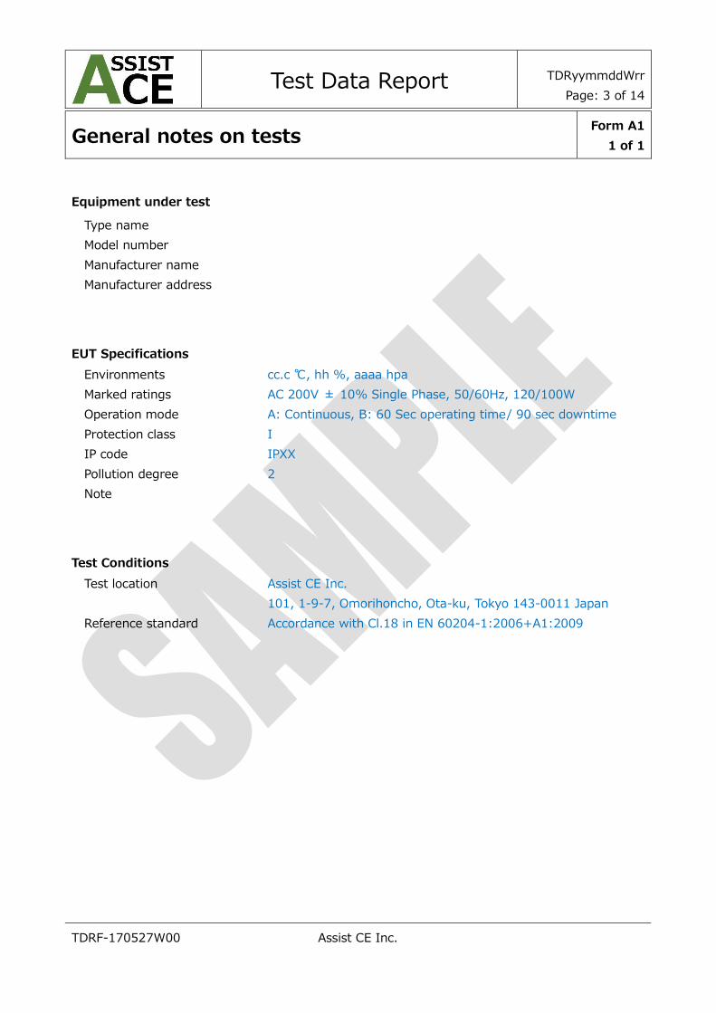
Equipment under test
Type name
Model number
Manufacturer name
Manufacturer address
EUT Specifications
Environments cc.c ℃, hh %, aaaa hpa
Marked ratings AC 200V ± 10% Single Phase, 50/60Hz, 120/100W
Operation mode A: Continuous, B: 60 Sec operating time/ 90 sec downtime
Protection class I
IP code IPXX
Pollution degree 2
Note
Test Conditions
Test location Assist CE Inc.
101, 1-9-7, Omorihoncho, Ota-ku, Tokyo 143-0011 Japan
Reference standard Accordance with Cl.18 in EN 60204-1:2006+A1:2009

Test Data Report
TDRyymmddWrr
Page: 4 of 14
TDRF-170527W00 Assist CE Inc.
Safety function test Form C1
1 of 2
Description Accordance with Cl.18 in EN 60204-1:2006+A1:2009
EUT Specifications
Marked ratings AC 200V ± 10% Single Phase, 50/60Hz, 120/100W
Operation mode A: Continuous, B: 60 Sec operating time/ 90 sec downtime
Test Conditions
Environments cc.c ℃, hh %, aaaa hPa
Input Voltage AC 200V, 50Hz
Test Method Power Meter
Test Points Following table
Test time 1 min
No. Test Point Result
Interlocking switch
/ Front door of processing room
When the door is open, the machine cannot activate
power circuits relevant to moving parts.
During the machine activate, the door cannot be
opened if the power source cut off. The machine
cannot restart without initializing process by voluntary
action.
[photo]
FAIL
The locking device releases immediately when the OFF
button is pushed and the mode switch turned to
maintenance, whether the spindle rotates still high.
Mode change switch
/ operation panel
FAIL
AS soon as the mode select switch turn to manual
mode, it is possible that operator releases the interlock
device on the door, whether the spindle rotetes still
high.
[photo]
EMO switch
/ operation panel, nearby front
door of processing room
All moving parts stop immediately. MCxx, MCxx are
opened.
The machine cannot restart unless initializing with
voluntary action.
[photo]

Test Data Report
TDRyymmddWrr
Page: 5 of 14
TDRF-170527W00 Assist CE Inc.
Item Equipment/Model, Manufacturer Serial No. Calibration Due Note
― ― ― ― ―
Date yyyy-mm-dd Tested by S. Watanabe

Test Data Report
TDRyymmddWrr
Page: 6 of 14
TDRF-170527W00 Assist CE Inc.
Sound pressure measurement Form D1
1 of 2
Description Accordance with Annex I of Machinery Directive
EUT Specifications
Marked ratings AC 200V ± 10% Single Phase, 50/60Hz, 120/100W
Operation mode A: Continuous, B: 60 Sec operating time/ 90 sec downtime
Test Conditions
Environments cc.c ℃, hh %, aaaa hPa
Input Voltage AC 200V, 50Hz
Test Method Sound level meter
Measurement Points Following figure and table
Measurement distance 1 m from surface of EUT
Measurement height 1.6 m
Measurement time 120 s
No. Measurement
Point
Operation
mode
Input
Voltage
[V]
Input
Frequency
[Hz]
LA [dB(A)] LCpk [dB]
1 A A 220 60
2 B A 220 60
3 C A 220 60
4 D A 220 60
Note: LA: A-weighted emission sound pressure level
LCpk: The peak C weighted instantaneous sound pressure level

Test Data Report
TDRyymmddWrr
Page: 7 of 14
TDRF-170527W00 Assist CE Inc.
Sound pressure measurement Form D1
2 of 2
[photo]
Item Equipment/Model, Manufacturer Serial No. Calibration Due Note
1 Sound Level Meter / NL52EX, RION 932279 2017-11 SL1
Date yyyy-mm-dd Tested by S. Watanabe
EUT
Point
A
Point
B
Point
C
Point
D

Test Data Report
TDRyymmddWrr
Page: 8 of 14
TDRF-170527W00 Assist CE Inc.
Leakage current measurement Form E1
1 of 2
Description For Cl.8.2.8 in EN 60204-1:2006+A1:2009
EUT Specifications
Marked ratings AC 200V ± 10% Single Phase, 50/60Hz, 120/100W
Operation mode A: Continuous, B: 60 Sec operating time/ 90 sec downtime
Test Conditions
Environments cc.c ℃, hh %, aaaa hPa
Input Voltage AC 200V
Input Frequency 50Hz
L-N condition Normal / Reverse
Abnormal condition ―: (Normal), A: Open PE
Measurement Method Leakage Current Meter / Current Clamp (ground current)
Measurement Points Following table
Measurement time 1 min
No. Measurement Point
Test Condition
Measured
[mA] Input
Voltage
[V]
Input
Frequency
[Hz]
L-N
Condition
Abnormal
Condition
1 Mains earth 220 60 Normal ―
2 Mains earth 220 60 Reverse ―
3 Enclosure 220 60 Normal ―
4 Enclosure 220 60 Reverse ―
5 Enclosure 220 60 Normal A
6 Enclosure 220 60 Reverse A
Test Data Report
TDRyymmddWrr
Page: 9 of 14
TDRF-170527W00 Assist CE Inc.
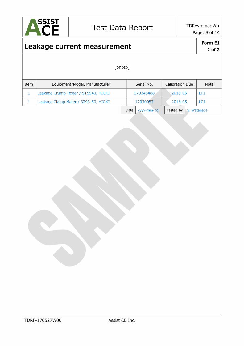
Leakage current measurement Form E1
2 of 2
[photo]
Item Equipment/Model, Manufacturer Serial No. Calibration Due Note
1 Leakage Crump Tester / ST5540, HIOKI 170348488 2018-05 LT1
1 Leakage Clamp Meter / 3293-50, HIOKI 17030057 2018-05 LC1
Date yyyy-mm-dd Tested by S. Watanabe

Test Data Report
TDRyymmddWrr
Page: 10 of 14
TDRF-170527W00 Assist CE Inc.
Residual voltage measurement Form F1
1 of 2
Description Accordance with Cl.18 in EN 60204-1:2006+A1:2009
EUT Specifications
Marked ratings AC 200V ± 10% Single Phase, 50/60Hz, 120/100W
Operation mode A: Continuous, B: 60 Sec operating time/ 90 sec downtime
Test Conditions
Environments cc.c ℃, hh %, aaaa hPa
Input Voltage AC 200V, 50Hz
Measurement Method Oscilloscope, Probe
Measurement Points Following table
Measurement time 1 s, 5 s, 10 s
No. Measurement Point
Working
Voltage
[V]
Measurement Voltage
10 s after
[V]
5 s after
[V]
1 s after
[V]
1 L1 to PE / MAIN 220 ― ―
2 L2 to PE / MAIN 220 ― ―
3 L3 to PE / MAIN 220 ― ―
4 L1 to L2 / MAIN 220 ― ―
5 L2 to L3 / MAIN 220 ― ―
6 L3 to L1 / MAIN 220 ― ―

Test Data Report
TDRyymmddWrr
Page: 11 of 14
TDRF-170527W00 Assist CE Inc.
Residual voltage measurement Form F1
2 of 2
[photo]
Item Equipment/Model, Manufacturer Serial No. Calibration Due Note
1 Digital Oscilloscope / TDS3014, TEKTRONIX B012142 2018-05
2 Probe (100:1) / 701947, YOKOGAWA ― 2018-05 ACE-P1
3 Probe (100:1) / 701947, YOKOGAWA ― 2018-05 ACE-P2
4 Probe (100:1) / 701947, YOKOGAWA ― 2018-05 ACE-P3
Date yyyy-mm-dd Tested by S. Watanabe

Test Data Report
TDRyymmddWrr
Page: 12 of 14
TDRF-170527W00 Assist CE Inc.
Continuity of protective circuit test Form G1
1 of 2
Description Accordance with Cl.18 in EN 60204-1:2006+A1:2009
Test Conditions
Environments cc.c ℃, hh %, aaaa hPa
Test Method Earth continuity tester
Test Points Following table
Test Current 25 A
Test Frequency 60 Hz
Measurement time 120 s
No. Test Point
Cross
Section
Size of PE
Conductor
Max.
Permitted
Resistance
[Ω]
Resistance
[Ω]
Voltage
[V]
Result
Pass/Fail
1 Left door of control
panel ― ―
2 Right door of control
panel ― ―
3 Interconnection box 1 ―
4 M1 ―
Continuity of protective circuit test Form G1
2 of 2
[photo]
Item Equipment/Model, Manufacturer Serial No. Calibration Due Note
1 Earth Continuity Tester / TOS6210, KIKUSUI XD001323 2018-05 EC1
Date yyyy-mm-dd Tested by S. Watanabe

Test Data Report
TDRyymmddWrr
Page: 13 of 14
TDRF-170527W00 Assist CE Inc.
Insulation resistance measurement Form N1
1 of 1
Description Accordance with Cl.18 in EN 60204-1:2006+A1:2009
Test Conditions
Environments cc.c ℃, hh %, aaaa hPa
Test Voltage Following Teble
Test Time 1 min
Devices disconnected Z1 for MAINS
No. Test Point
Test
Voltage
[Vdc]
Measured
[MΩ]
Result
Pass/Fail
1 L1, L2, L3 / MAIN – PE 500 >100
2 U1, V1, W1 / MC1 - PE 500 >100
[photo]
Item Equipment/Model, Manufacturer Serial No. Calibration Due Note
1 Insulation Tester / IR4042-11, HIOKI 170324334 2018-05 IT1
Date yyyy-mm-dd Tested by S. Watanabe

Test Data Report
TDRyymmddWrr
Page: 14 of 14
TDRF-170527W00 Assist CE Inc.
Voltage withstanding test Form O1
1 of 1
Description Accordance with Cl.18 in EN 60204-1:2006+A1:2009
Test Conditions
Environments cc.c ℃, hh %, aaaa hPa
Test Voltage Following Table
Test Frequency 60 Hz
Test Time 1 s
Devices disconnected Z1 for MAINS
No. Test Point - Refer to Test Points Table for details
Test
Voltage
[V]
Result
Pass/Fail
1 L1, L2, L3 / MAIN – PE
2 U1, V1, W1 / MC1 - PE
[photo]
Item Equipment/Model, Manufacturer Serial No. Calibration Due Note
1 Voltage Withstand Tester / TOS5301 , KIKUSUI WM001177 2018-05
Date yyyy-mm-dd Tested by S. Watanabe