samand - ikco-club
TRANSCRIPT
SAMAND (XU7JPL3)
Service Manual
Cooling, Manifold and Exhaust
Система охлаждения двигателя
Система выпуска отработавших газов

Chapter:
Section:
Product: SAMAND XU7JPL3
Cooling,Manifold and Exhaust
I
SAMAND Service Manual
Foreword:
This Service Manual contains descriptions of the following categories for the Samand:
Cooling , Manifold and Exhaust
This manual should be used as service manual and s workbook for training instructors and technicians. We reserve the right to introduce change without prior notice.

Contents
Cooling system . . . . . . . . . . . . . . . . . . . . . . . . . . . . . . . . . . . . . . . . . . . . . . . . . . . . . . 1
Technical data
Thermostat . . . . . . . . . . . . . . . . . . . . . . . . . . . . . . . . . . . . . . . . . . . . . . . . . . . . . . . . . . . . . 3
Cooling system . . . . . . . . . . . . . . . . . . . . . . . . . . . . . . . . . . . . . . . . . . . . . . . . . . . . . . . . . . 3
Hoses . . . . . . . . . . . . . . . . . . . . . . . . . . . . . . . . . . . . . . . . . . . . . . . . . . . . . . . . . . . . . . . . . 3
Torque settings . . . . . . . . . . . . . . . . . . . . . . . . . . . . . . . . . . . . . . . . . . . . . . . . . . . . . . . . . . 4
Special tools
Coolant filling cylinder . . . . . . . . . . . . . . . . . . . . . . . . . . . . . . . . . . . . . . . . . . . . . . . . . . . . . 5
Electronic measuring tool . . . . . . . . . . . . . . . . . . . . . . . . . . . . . . . . . . . . . . . . . . . . . . . . . . 5
Crankshaft pulley extractor . . . . . . . . . . . . . . . . . . . . . . . . . . . . . . . . . . . . . . . . . . . . . . . . . 5
Camshaft setting rods . . . . . . . . . . . . . . . . . . . . . . . . . . . . . . . . . . . . . . . . . . . . . . . . . . . . . 6
Flywheel stop . . . . . . . . . . . . . . . . . . . . . . . . . . . . . . . . . . . . . . . . . . . . . . . . . . . . . . . . . . . 6
Technical description
System overview . . . . . . . . . . . . . . . . . . . . . . . . . . . . . . . . . . . . . . . . . . . . . . . . . . . . . . . . . 7
Cooling system description . . . . . . . . . . . . . . . . . . . . . . . . . . . . . . . . . . . . . . . . . . . . . . . . . 8
Adjustment and replacement
General precautions . . . . . . . . . . . . . . . . . . . . . . . . . . . . . . . . . . . . . . . . . . . . . . . . . . . . . . 9
Cooling system hoses . . . . . . . . . . . . . . . . . . . . . . . . . . . . . . . . . . . . . . . . . . . . . . . . . . . . . 10
- Radiator hoses . . . . . . . . . . . . . . . . . . . . . . . . . . . . . . . . . . . . . . . . . . . . . . . . . . . . . . . 10
- Conventional hose connections . . . . . . . . . . . . . . . . . . . . . . . . . . . . . . . . . . . . . . . . . . . 11
Draining filling and bleeding . . . . . . . . . . . . . . . . . . . . . . . . . . . . . . . . . . . . . . . . . . . . . . . . 12
Thermostat remove and refit . . . . . . . . . . . . . . . . . . . . . . . . . . . . . . . . . . . . . . . . . . . . . . . . 14
Cooling pump remove and refit . . . . . . . . . . . . . . . . . . . . . . . . . . . . . . . . . . . . . . . . . . . . . . 15
Water outlet elbow remove and refit . . . . . . . . . . . . . . . . . . . . . . . . . . . . . . . . . . . . . . . . . . . 22
Radiator remove and refit . . . . . . . . . . . . . . . . . . . . . . . . . . . . . . . . . . . . . . . . . . . . . . . . . . 23
Exhaust system and manifold . . . . . . . . . . . . . . . . . . . . . . . . . . . . . . . . . 25
Technical data
Torque settings . . . . . . . . . . . . . . . . . . . . . . . . . . . . . . . . . . . . . . . . . . . . . . . . . . . . . . . . . . 27
Technical description
System overview . . . . . . . . . . . . . . . . . . . . . . . . . . . . . . . . . . . . . . . . . . . . . . . . . . . . . . . . . 29

Adjustment and replacement
Exhaust pipes remove and refit . . . . . . . . . . . . . . . . . . . . . . . . . . . . . . . . . . . . . . . . . . . . . . 31
- Front pipe . . . . . . . . . . . . . . . . . . . . . . . . . . . . . . . . . . . . . . . . . . . . . . . . . . . . . . . . . . . . 31
- Intermediate pipe and centre silencer . . . . . . . . . . . . . . . . . . . . . . . . . . . . . . . . . . . . . . . 32
- Rear pipe and main silencer . . . . . . . . . . . . . . . . . . . . . . . . . . . . . . . . . . . . . . . . . . . . . . 33
Exhaust system complete remove and refit . . . . . . . . . . . . . . . . . . . . . . . . . . . . . . . . . . . . . 34
Exhaust heat shield remove and refit . . . . . . . . . . . . . . . . . . . . . . . . . . . . . . . . . . . . . . . . . . 35
Exhaust manifold remove and refit . . . . . . . . . . . . . . . . . . . . . . . . . . . . . . . . . . . . . . . . . . . . 36

Cooling System
1

Technical data
Thermostat
Starts to open at - 88°c
Fully open at -100°c
Cooling system
Capacity - 7 litres
Antifreeze
28% mixture protection down to - 15°c
50% mixture protection down to - 30°c
Hoses
Hose connection to the radiator is with a bayonet
type connector which seals connection with an
'O' ring.
W74S002
W74S003
W74S004

Torque settings
W74S001
2
1
1. Thermostat housing bolts 15 Nm. 2. Coolant pump bolts 18Nm.

Special tools
Coolant filling cylinder
(-).0173
Electronic measuring tool
SEEM C. Trionic 87
Crankshaft pulley extractor
(-).174
T.(-).0173
T.SEEM87
T.(-).0174

Camshaft setting rod
(-).0132R
Crankshaft setting rod
(-).0153G
Flywheel stop
9765.54
T.(-).0132R
T.(-).0153G
T.9765.54
6 Special tools

Technical description
System overview
W74D001
6
9
8
1
7
3
95
1. Radiator (incorporating expansion tank
2. Coolant Pump
3. Water Outlet
4. Thermostat Housing
5. Heater
6. Top Radiator Hose
7. Bottom Radiator Hose
8. Heater Hose (Feed)
9. Heater Hose (Return)

Cooling system description
The cooling system is of pressurised type, comprising a coolant pump driven by the timing belt, an aluminium crossflow
radiator with integral expansion tank, electric cooling fans, a thermostat, heater matrix, and all associated hoses and
switches.
The system functions as follows. Cold coolant in the bottom of the radiator passes through the bottom hose to the
coolant pump, where it is pumped around the cylinder block and head passages. After cooling the cylinder bores,
combustion surfaces and valve seats, the coolant reaches the underside of the thermostat, which is initially closed. The
coolant passes through the heater, and is returned via the cylinder block to the coolant pump.
When the engine is cold, the coolant circulates only through the cylinder block, cylinder head, and heater. When the
coolant reaches a predetermined temperature, the thermostat opens, and the coolant passes through the top hose to
the radiator. As the coolant circulates through the radiator, it is cooled by the inrush of air when the car is in forward
motion. The airflow is supplemented by the action of the electric cooling fans when necessary. Upon reaching the
bottom of the radiator, the coolant has now cooled, and the cycle is repeated.
When the engine is at normal operating temperature, the coolant expands, and some of it is displaced into the
expansion tank, incorporated in the side of the radiator. Coolant collects in the tank, and is returned to the radiator
when the system cools.
The electric cooling fans mounted in front of the radiator are controlled by a thermostatic switch. At a predetermined
coolant temperature, the switch/sensor actuates the fan.

Adjustment and replacement
General Precautions
W74R001
Warning: Do not attempt to remove the expansion tank
filler cap, or to disturb any part of the cooling system,
while the engine is hot, as there is a high risk of
scalding. If the expansion tank filler cap must be
removed before the engine and radiator have fully
cooled (even though this is not recommended), the
pressure in the cooling system must first be relieved.
Cover the cap with a thick layer of cloth, to avoid
scalding, and slowly unscrew the filler cap until a
hissing sound is heard. When the hissing has stopped,
indicating that the pressure has reduced, slowly
unscrew the filler cap until it can be removed; if more
hissing sounds are heard, wait until they have stopped
before unscrewing the cap completely. At all times,
keep well away from the filler cap.
Do not allow antifreeze to come into contact with your
skin, or with the painted surfaces of the vehicle. Rinse
off spills immediately, with plenty of water. Never leave
antifreeze lying around in an open container, or in a
puddle on the garage floor. Antifreeze can be fatal if
ingested.
If the engine is hot, the electric cooling fan may start
rotating even if the engine is not running. Be careful to
keep your hands, hair, and any loose clothing well clear
when working in the engine compartment.

W74R002
10 Adjustment and replacement
Cooling system hoses
Important
Refer to the warnings given on page 9 of this book,
before proceeding. Hoses should only be disconnected
once the engine has cooled sufficiently to avoid
scalding.
If inspection of the system reveals a faulty hose, it must
be renewed as follow. First drain the cooling system. If
the coolant is not due for renewal, it may be re-used,
providing it is collected in a clean container.
To disconnect a hose, proceed as follows, according to
the type of hose connection.
Radiator hoses
Removal
The radiator hoses are connected to the radiator using
a plastic bayonet-type connection. To disconnect, twist
the end of the hose (with the connector) anti-clockwise
until the clips on the connector are clear of the retaining
lugs on the radiator stub, then pull the end of the hose
from the radiator. Recover the �O� ring from the end of
the hose connector.

11Adjustment and replacement
W74S004
W74R004
To fit
Fit a new �O� ring to the hose connector, then reconnect
the hose.
Twist the end of the hose fully clockwise to ensure that
the retaining clips are engaged with the lugs on the
radiator stub.
Conventional hose connections
To disconnect a hose, use a screwdriver to slacken or
release the clips, then move them along the hose, clear
of the relevant inlet/outlet. Carefully work the hose free.
The hoses can be removed with relative ease when
new - on an older car, they may have stuck.
If a hose proves to be difficult to remove, try to release
it by rotating its ends before attempting to free it. Gently
prise the end of the hose with a blunt instrument (such
as a flat-bladed screwdriver), but do not apply too much
force, and take care not to damage the pipe stubs or
hoses. Do not use excessive force when attempting to
remove the hose. If all else fails, cut the hose with a
sharp knife, then slit it so that it can be peeled off in two
pieces. Check first, however, that a new hose is readily
available.
When fitting a hose, first slide the clips onto the hose,
then work the hose into position. Use standard worm-
drive clips when refitting the hose. If the hose is stiff,
use a little soapy water as a lubricant, or soften the
hose by soaking it in hot water. Do not use oil or
grease, which may attack the rubber.
Work the hose into position, checking that it is correctly
routed, then slide each clip back along the hose until it
passes over the flared end of the relevant inlet/outlet,
before tightening the clip securely.
Refill the cooling system with reference to page ?
Check thoroughly for leaks as soon as possible after
disturbing any part of the cooling system.

W74R005
1
W74R006
1
W74R007
12 Adjustment and replacement
Draining, filling and bleeding
The Cooling System
see precautions page 9
Special tool
1 Filling cylinder (-) 0173
1 With engine completely cold remove the
expansion tank filler cap. Turn cap anti clockwise
until it reaches the first stop. Wait for any pressure
to release. Turn cap anti-clockwise to second stop
and remove.
2 Drain radiator by turning tap anti-clockwise. Tap is
located at the bottom right of the radiator. Fit tube
to collect coolant into container.

13Adjustment and replacement
W74R008
3
W74R010
2
W74R011
3
3 To assist draining it may be necessary to open
bleed screws located on thermostat housing.]
4 When the flow of coolant stops reposition
container below the cylinder block at the plug on
the front of the cylinder block.
Remove plugs and allow coolant to drain into
container.
Filling
1 Close radiator and cylinder block drain plugs.
2 Open bleed screw at the top of the radiator.
3 Fit the filling cylinder (-)0173 to the expansion tank.
Note: Keep the filling cylinder full to the maximum.
Close the bleed valves as soon as the coolant flow from
them is continuous without bubbles.
Remove the filling cylinder.
Fit the expansion tank cap tighten to the second notch.
Start the engine (engine speed 1500 rpm).
Maintain this speed for three cooling cycles (fans
starting and stopping).
Allow the engine run at idling speed for a few minutes.
Stop the engine.
Wait for at least 10 minutes.
Remove the filler cap carefully.
Top up the coolant lever.
Fit the expansion tank cap. Tighten to second notch.

W74R012
4
4
W74R013
5
W74R014
14 Adjustment and replacement
Thermostat remove and refit
To remove
1 Disconnect battery negative terminal.
2 Drain cooling system.
3 Release any wiring or hoses to improve access to
housing.
4 Remove two bolts securing thermostat housing.
5 Lift thermostat from the housing, noting which way
it is fitted.
6 Test thermostat for opening and closing within
temperatures shown in technical data. If faulty
renew.
If correct check the rubber sealing ring for
damage or deterioration.
To fit
Refitting is a reversal of the removal procedure.
Bleed cooling system.

15Adjustment and replacement
W74R0211 3 2
4 5
W74R024
W74R0156
5
Coolant pump remove and refit
To remove
Special Tools
1 Camshaft gear setting rod (-).0132R.
2 Crankshaft setting rod (-).0153G.
3 Flywheel stop. 9765.54.
4 Belt tension measuring equipment seem c. Trionic
type 105.5.
5 Crankshaft pulley extractor (-).0174.
1 Drain the cooling system.
2 Raise vehicle and support securely and remove
front right hand road wheel.
3 Remove wheel arch liner.
Note: Radiator bottom hose is fixed to liner with two
plastic ties.
4 Remove accessory drive belt.
5 Release clips and remove fuel pipes from the
upper timing belt cover.
6 Remove two bolts at the base of the cover and
remove cover.

W74R016
7
W74R025
8
9
8
W74R017
10
16 Adjustment and replacement
7 Rotate the crankshaft pulley until the timing hole
in the camshaft sprocket is aligned with its
corresponding hole in the cylinder head.
Note: that the holes are aligned when the sprocket hole
is in the 8 �O� clock position. Insert setting rod
(-).132R into camshaft and setting rod (-).153G into
crankshaft.
The crankshaft and camshaft are now locked in
position, preventing unnecessary rotation.
8 Remove clutch housing bottom closing plate.
9 Lock flywheel with stop 9765.54 and remove
crankshaft setting rod.
10 Remove centre cover. Remove two upper screws,
move cover up to release from locating screws
which retains lower cover.

17Adjustment and replacement
W74R018
11
W74R019
12
W74R020
13
11 Remove crankshaft pulley using pulley extractor
(-).0174.
12 Remove lower cover. If auxiliary equipment, such
as air conditioning is fitted, it may be necessary to
remove the auxiliary drivebelt tensioner. This will
assist the removal of the lower cover.
13 Loosen the timing belt tensioner pulley retaining
bolt. Pivot the pulley clockwise using a square
section key and tighten the retaining bolt. Support
engine with a jack.
W74R022
14
15
W74R023
16
W74R056
1
18 Adjustment and replacement
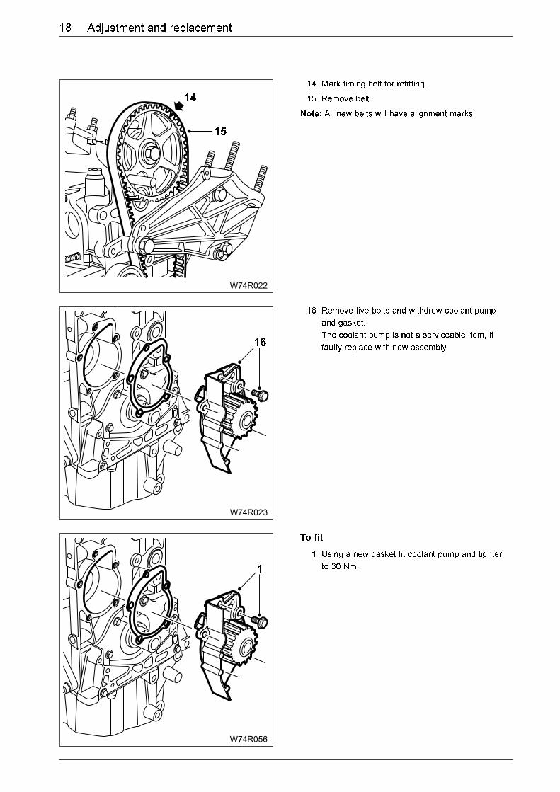
14 Mark timing belt for refitting.
15 Remove belt.
Note: All new belts will have alignment marks.
16 Remove five bolts and withdrew coolant pump
and gasket.
The coolant pump is not a serviceable item, if
faulty replace with new assembly.
To fit
1 Using a new gasket fit coolant pump and tighten
to 30 Nm.

19Adjustment and replacement
W74R026
W74R027
4
4
W74R028
5
2 Ensure that the camshaft setting tool is in
position.
3 Temporarily refit crankshaft and insert setting tool
to ensure crankshaft is correctly positioned. If
correct remove setting tool and remove crankshaft
pulley.
Note: Check timing belt for wear or damage. Renew if
there is the slightest doubt about its condition or if the
vehicle has covered more than 60,000 Km with the
existing belt, renew as a matter of course.
4 Fit timing belt into position ensuring that any
arrows are positioned in the direction of rotation.
If existing belt is being reused, line up marks.
Ensure the front run is taut and any slack is on
the tensioner pulley side.
5 Loosen the tensioner pulley retaining bolt. Using
the square-section key, pivot the pulley
anti-clockwise to remove all free play from the
timing belt.

W74R029
8
7
6
W74R030
W74R033
10
10
20 Adjustment and replacement
6 Remove camshaft setting rod. The special belt
tension measuring equipment should be fitted to
the �front run� of the timing belt. The tensioner
roller should be adjusted so that the initial belt
tension is 30 ± 2 units.
7 Tighten the pulley retaining bolt to 20 Nm.
8 Refit the crankshaft pulley again, tightening
retaining bolt by hand only.
Rotate the crankshaft through at least two
complete rotations in a clockwise direction
(viewed from the right-hand end of the engine).
Do not at any time rotate the crankshaft anti-
clockwise. Both camshaft and crankshaft timing
holes should be aligned so that the locking pins
can be easily inserted. This indicates that the
valve timing is correct.
9 The final belt tension on the �front run� of the belt
should be between 42 to 46 seem units. Readjust
the tensioner pulley position as required, then re-
tighten the retaining bolt to 20 Nm. Rotate the
crankshaft through a further two rotations
clockwise, and re-check the tension. Repeat this
procedure as necessary until the correct tension
reading is obtained after rotating the crankshaft.
Remove crankshaft pulley.
10 Refit lower cover.

21Adjustment and replacement
W74R034
11
W74R035
12
W74R03113
11 Coat the bolt with a threadlock compound, refit
crankshaft pulley, tighten 110 Nm.
12 Fit centre cover. Ensure bottom fixing is retained
by pushing down onto lower cover screws.
Tighten two upper bolts to 8 Nm.
13 Refit upper cover. Tighten 8 Nm. Refit pipes to
upper cover. Refit wheel arch liner.
Note: Fit new cable ties (bottom hose to wheel arch liner).
14 Tighten the wheel bolts to 85Nm.

W74R032
3
3
4
4
W74R036
5
5
6
22 Adjustment and replacement
Water outlet elbow
To remove
1 Raise vehicle and support securely.
2 Drain coolant system.
3 Remove two front nuts from the engine undertray.
4 Support tray and remove three rear bolts and
lower and remove undertray.
5 From underneath vehicle remove hose to lower
radiator and hose to heater outlet.
6 Remove two bolts and remove water outlet elbow.
Collect sealing ring.
To fit
1 Refitting is a reversal of the removal procedure.
Ensure that the mating surfaces are clean and
check condition of and renew if necessary the
sealing ring. Tighten outlet elbow bolts to .15 Nm.
Refit hoses and fill and bleed the coolant system.

23Adjustment and replacement
W74R037
3
3 2
W74R038
4
W74R039
5
5
6
6
Radiator remove and refit
To remove
1 Drain cooling system. See page 12
2 Remove air intake hose.
3 Remove 2 screws and move map sensor
complete with bracket connector and hose.
4 Disconnect the upper radiator hose.
5 Raise vehicle and remove two nuts at the front of
the body undertray.
6 Support the undertray and remove three bolts
from the rear of the undertray. Remove undertray.

W74R040
7
8
W74R041
24 Adjustment and replacement
7 From underneath vehicle remove lower coolant
hose to radiator.
Note: this operation can be difficult.
8 Release two wire clips at each end of the radiator
and push toward engine slightly and lift up and
out of the vehicle.
To fit
Refitting is a reversal of the removal procedure.
Note: ensure the lower lugs are correctly engaged with
the mounting rubbers in the body panel. Check �O� rings
on hose connections to radiator and renew if necessary.
Refill and bleed coolant system.

Exhaust system and manifold
25

Technical data
Torque settings
W74S005
4
5
2
3
1
1 Exhaust manifold to cylinder head 35 Nm
2 Heat shield to exhaust manifold (long bolts) 10 Nm
3 Heat shield to exhaust manifold (short bolts) 10 Nm
4 Exhaust front pipe to exhaust manifold 10 Nm
5 Front pipe/intermediate pipe/rear pipe clamping rings 20 Nm

Technical description
System overview
W74S002
Exhaust Manifold & Exhaust Pipes
The exhaust system consists of 3 parts.
1 Front pipe.
2 Intermediate pipe and centre silencer.
3 Rear pipe and main silencer.
The front pipe is of the spring loaded ball type to allow
for movement in the exhaust system.
All other joints are secured with clamp rings.
The system is secured throughout it length with rubber
mountings.
An earth strap is fitted from the exhaust pipe to the
body at the front pipe to centre silencer clamp fixing.
A heat shield is fitted underneath the fuel tank.

Adjustment and replacement
Exhaust pipes remove and refit
W74R042
W74R043
Each section of the exhaust can be removed
individually or the complete system can be removed as
a unit if one part needs attention it is easier to remove
the whole system and separate section on a bench.
Front pipe
1 Raise vehicle and support securely.
2 Remove nuts securing front pipe to exhaust
manifold. Recover spring cups and springs.
3 Remove nuts, washers and bolts from front pipe
to intermediate pipe clamp rings.
Note: That the earthing strap is fixed to clamp bolt.

W74R044
4
W74R045
1
W74R046
2
32 Adjustment and replacement
4 Remove front pipe and collect exhaust ball head.
Intermediate pipe and centre silencer
1 Remove nuts, washers and bolts from front pipe
to intermediate pipe clamp rings.
Note: That the earthing strap is fixed to clamp bolts.
2 Remove nuts, washers and bolts from the
intermediate pipe to the rear pipe clamping rings.

33Adjustment and replacement
W74R047
3
W74R048
1
W74R049
3 Release mounting rubber and remove
intermediate pipe.
Rear pipe & main silencer
1 Remove nuts, washers and bolts from the rear
pipe to the intermediate pipe clamp rings.
2 Release rear pipe and main silencer from the two
retaining rubbers and remove rear pipe.

W74R050
2
2
W74R051
3
W74R052
34 Adjustment and replacement
Exhaust system complete remove and refit.
To remove
1 Raise vehicle and support securely.
2 Remove nuts securing front pipe to exhaust
manifold. Recover spring cups and springs.
3 Remove earth strap at the body fixing point.
4 Remove two rubber mountings from rear pipe and
main silencer.

35Adjustment and replacement
W74R053
5
W74R055
2
1
1
1
1
5 Remove rubber mounting at the intermediate pipe
and remove exhaust system complete.
To fit
Refitting is a reversal of the removal procedure.
Exhaust heat shield remove and refit
1 Remove four fixing screws to fuel tank.
2 Remove shield from behind exhaust pipe.
To fit
Refitting is a reversal of the removal procedure.

W74R0573
W74R058
44
44
4
W74R059
7
6
5
36 Adjustment and replacement
Exhaust manifold remove and refit
To remove
Note: To remove the exhaust manifold care must be
taken as it is a difficult operation to undertake because
the upper heat shield is also the manifold gasket.
1 Disconnect battery earth cable.
2. Raise vehicle.
3. Remove exhaust front pipe from exhaust
manifold. Recover spring cups and springs.
Remove four lower nuts fixing manifold to cylinder
head
4 Lower vehicle. Remove air intake pipe. Release
two clips and remove two screws, remove air filter
cover.
5 Remove three pipes from cylinder head cover.
6 Release and move two fuel pipes aside.
7 Release pipe.
Note: The pipe is fixed also at ignition coil bracket.

37Adjustment and replacement
W74R060
9 5 1 4 8
10 6 2 3 7
W74R061
9
9
10
10
10
W74R06111
8 Remove ten bolts in the sequence shown and
remove cylinder head cover/air cleaner assembly.
9 Remove two long bolts and washers from heat
shield/gasket assembly. Collect spacers.
10 Remove two bolts from both ends of the lower
heat shield and withdraw heat shield.
11 Carefully lift upper heat shield gasket and remove
four upper nuts fixing manifold to cylinder head.
To fit
Refitting is a reversal of the removal procedure. Check
condition of heat shield/gasket assembly and renew if
necessary.

Technical Department Subject:
Cooling , Manifold & Exhaust Page: 35 of 41
Ref. No :1303R01802681/1
Cooling,Manifold & Exhaust IKCO Export after sales services department

Technical Department Subject:
Cooling , Manifold & Exhaust Page: 36 of 41
Ref. No :1303R01802681/1
Cooling,Manifold & Exhaust IKCO Export after sales services department

Technical Department Subject:
Cooling , Manifold & Exhaust Page: 37 of 41
Ref. No :1303R01802681/1
Cooling,Manifold & Exhaust IKCO Export after sales services department