sam-e & mini sam-e short absorption manifold engineering...
TRANSCRIPT

1503529-B
SAM-eSAM-e & mini SAM-e Short Absorption Manifold
Engineering Manual

2008-07-18
PROPRIETARY NOTICEThis document and the information disclosed herein are proprietary data of WALTER MEIER LTD. Neither this document nor the information contained herein shall be reproduced used, or disclosed to others without the written authorization of WALTER MEIER LTD., except to the extent required for installation or maintenance of recipient’s equipment. All references to the NORTEC name should be taken as referring to WALTER MEIER LTD.
LIABILITY NOTICENORTEC does not accept any liability for installations of humidity equipment installed by unqualified personnel or the use of parts/components/equipment that are not authorized or approved by NORTEC.
COPYRIGHT NOTICECopyright 2008, WALTER MEIER LTD. All rights reserved.
RECORD OF REVISIONSFor each revision, put the revised pages in your manual and discard the superseded pages. Write therevision number and revision date, date put in manual, and the incorporator’s initials in the applicablecolumns on the Record of Revisions.
Revision Number
Revision Date
Date Put In Manual By
Revision Number
Revision Date
Date Put In Manual By

2008-07-18
TABLE OF CONTENTSSubject Page
10-00 INTRODUCTION
1. INTRODUCTION. . . . . . . . . . . . . . . . . . . . . . . . . . . . . . . . . . . . . . . . . . . . . . . . . . . . . . . . 22. FEATURES . . . . . . . . . . . . . . . . . . . . . . . . . . . . . . . . . . . . . . . . . . . . . . . . . . . . . . . . . . . . 2
10-10 STEAM ABSORPTION
1. DETERMINING THE STEAM ABSORPTION DISTANCE . . . . . . . . . . . . . . . . . . . . . . . . 62. STATIC AIR PRESSURE . . . . . . . . . . . . . . . . . . . . . . . . . . . . . . . . . . . . . . . . . . . . . . . . . 93. CONDENSATE LOOSES . . . . . . . . . . . . . . . . . . . . . . . . . . . . . . . . . . . . . . . . . . . . . . . . . 94. CORRECT CHOICE OF PRODUCT APPLICATIONS (WITHIN SAM-E). . . . . . . . . . . . 10
10-20 PRODUCT SELECTION
1. SAM-E HEADER SELECTION . . . . . . . . . . . . . . . . . . . . . . . . . . . . . . . . . . . . . . . . . . . . 142. STEAM TUBE SELECTION . . . . . . . . . . . . . . . . . . . . . . . . . . . . . . . . . . . . . . . . . . . . . . 193. SAM-E STEAM INLET CONFIGURATION SELECTION . . . . . . . . . . . . . . . . . . . . . . . . 224. MINI SAM-E . . . . . . . . . . . . . . . . . . . . . . . . . . . . . . . . . . . . . . . . . . . . . . . . . . . . . . . . . . 235. SELECT OPTIONS . . . . . . . . . . . . . . . . . . . . . . . . . . . . . . . . . . . . . . . . . . . . . . . . . . . . . 24
10-30 TYPICAL INSTALLATION DRAWINGS1. . . . . . . . . . . . . . . . . . . . . . . . . . . . . . . . . . . . . . . . . . . . . . . . . . . . . . . . . . . . . . . . . . . . . 25
10-40 SPECIFICATION
1. GENERAL . . . . . . . . . . . . . . . . . . . . . . . . . . . . . . . . . . . . . . . . . . . . . . . . . . . . . . . . . . . . 342. PRODUCTS . . . . . . . . . . . . . . . . . . . . . . . . . . . . . . . . . . . . . . . . . . . . . . . . . . . . . . . . . . 353. EXECUTION . . . . . . . . . . . . . . . . . . . . . . . . . . . . . . . . . . . . . . . . . . . . . . . . . . . . . . . . . . 36
APPENDIX 1 - INLET ADAPTER CONFIGURATIONS1. . . . . . . . . . . . . . . . . . . . . . . . . . . . . . . . . . . . . . . . . . . . . . . . . . . . . . . . . . . . . . . . . . . . . 39
WARRANTY
2008-07-18
LIST OF FIGURESFigure Page
10-00 INTRODUCTIONFigure 1. SAM-e . . . . . . . . . . . . . . . . . . . . . . . . . . . . . . . . . . . . . . . . . . . . . . . . . . . . . . . . . . 3Figure 2. Cross Section of Distributor Pipe . . . . . . . . . . . . . . . . . . . . . . . . . . . . . . . . . . . . . 3
10-10 STEAM ABSORPTIONFigure 1. Absorption Distance 3” Centers . . . . . . . . . . . . . . . . . . . . . . . . . . . . . . . . . . . . . . 8Figure 2. Absorption Distance 6” Centers . . . . . . . . . . . . . . . . . . . . . . . . . . . . . . . . . . . . . . 8Figure 3. Absorption Distance 9” Centers . . . . . . . . . . . . . . . . . . . . . . . . . . . . . . . . . . . . . . 8Figure 4. Absorption Distance 12” Centers . . . . . . . . . . . . . . . . . . . . . . . . . . . . . . . . . . . . . 8Figure 5. SAM-e General Dimensions . . . . . . . . . . . . . . . . . . . . . . . . . . . . . . . . . . . . . . . . 10Figure 6. mini SAM-e General Dimensions . . . . . . . . . . . . . . . . . . . . . . . . . . . . . . . . . . . . 11
10-20 PRODUCT SELECTIONFigure 1. Header . . . . . . . . . . . . . . . . . . . . . . . . . . . . . . . . . . . . . . . . . . . . . . . . . . . . . . . . 15Figure 2. SAM-e Stand. . . . . . . . . . . . . . . . . . . . . . . . . . . . . . . . . . . . . . . . . . . . . . . . . . . . 15Figure 3. mini SAM-e Tube Insulation . . . . . . . . . . . . . . . . . . . . . . . . . . . . . . . . . . . . . . . . 19
10-30 TYPICAL INSTALLATION DRAWINGSFigure 1. SAM-e Exploded View . . . . . . . . . . . . . . . . . . . . . . . . . . . . . . . . . . . . . . . . . . . . 26Figure 2. SAM-e Insulated Exploded View. . . . . . . . . . . . . . . . . . . . . . . . . . . . . . . . . . . . . 27Figure 3. mini SAM-e Insulated Exploded View . . . . . . . . . . . . . . . . . . . . . . . . . . . . . . . . . 28Figure 4. Typical SAM-e Installation for Pressurized Steam Applications . . . . . . . . . . . . . 29Figure 5. Typical SAM-e Installation for Atmospheric Steam Applications. . . . . . . . . . . . . 30Figure 6. Typical mini SAM-e Installation for Pressurized Steam Applications . . . . . . . . . 31Figure 7. Typical mini SAM-e Installation for Atmospheric Steam Applications . . . . . . . . . 32
APPENDIX 1Figure 1. KIT - Header and Adapter Configuration. . . . . . . . . . . . . . . . . . . . . . . . . . . . . . . 40Figure 2. KIT 1 - Header and Adapter Configuration . . . . . . . . . . . . . . . . . . . . . . . . . . . . . 41Figure 3. KIT 2 - Header and Adapter Configuration . . . . . . . . . . . . . . . . . . . . . . . . . . . . . 42Figure 4. KIT 3 - Header and Adapter Configuration . . . . . . . . . . . . . . . . . . . . . . . . . . . . . 43Figure 5. KIT 4 - Header and Adapter Configuration . . . . . . . . . . . . . . . . . . . . . . . . . . . . . 44Figure 6. KIT 5 - Header and Adapter Configuration . . . . . . . . . . . . . . . . . . . . . . . . . . . . . 45Figure 7. KIT 6 - Header and Adapter Configuration . . . . . . . . . . . . . . . . . . . . . . . . . . . . . 46Figure 8. KIT 7 - Header and Adapter Configuration . . . . . . . . . . . . . . . . . . . . . . . . . . . . . 47Figure 9. KIT 8- Header and Adapter Configuration. . . . . . . . . . . . . . . . . . . . . . . . . . . . . . 48Figure 10. KIT 23 - Header and Adapter Configuration . . . . . . . . . . . . . . . . . . . . . . . . . . . . 49Figure 11. KIT 24 - Header and Adapter Configuration . . . . . . . . . . . . . . . . . . . . . . . . . . . . 50Figure 12. KIT 25 - Header and Adapter Configuration . . . . . . . . . . . . . . . . . . . . . . . . . . . . 51Figure 13. KIT 26 - Header and Adapter Configuration . . . . . . . . . . . . . . . . . . . . . . . . . . . . 52Figure 14. KIT 27 - Header and Adapter Configuration . . . . . . . . . . . . . . . . . . . . . . . . . . . . 53Figure 15. KIT 28 - Header and Adapter Configuration . . . . . . . . . . . . . . . . . . . . . . . . . . . . 54Figure 16. KIT 29 - Header and Adapter Configuration . . . . . . . . . . . . . . . . . . . . . . . . . . . . 55Figure 17. KIT 30 - Header and Adapter Configuration . . . . . . . . . . . . . . . . . . . . . . . . . . . . 56

2008-07-18
LIST OF TABLESTable Page
10-10 STEAM ABSORPTIONTable 1. Air Pressure Loss in AHU / Duct . . . . . . . . . . . . . . . . . . . . . . . . . . . . . . . . . . . . . . 9Table 2. Condensate Loss . . . . . . . . . . . . . . . . . . . . . . . . . . . . . . . . . . . . . . . . . . . . . . . . . 9
10-20 OPERATION
Table 1. SAM-e Stand . . . . . . . . . . . . . . . . . . . . . . . . . . . . . . . . . . . . . . . . . . . . . . . . . . . . 14Table 2. SAM-e Header - 3” Centers. . . . . . . . . . . . . . . . . . . . . . . . . . . . . . . . . . . . . . . . . 16Table 3. SAM-e Header - 6” Centers. . . . . . . . . . . . . . . . . . . . . . . . . . . . . . . . . . . . . . . . . 17Table 4. SAM-e Header - 9” Centers. . . . . . . . . . . . . . . . . . . . . . . . . . . . . . . . . . . . . . . . . 18Table 5. SAM-e Header - 12” Centers. . . . . . . . . . . . . . . . . . . . . . . . . . . . . . . . . . . . . . . . 18Table 6. 304 Stainless Steel Tubes. . . . . . . . . . . . . . . . . . . . . . . . . . . . . . . . . . . . . . . . . . 20Table 7. 409 Stainless Steel Tubes. . . . . . . . . . . . . . . . . . . . . . . . . . . . . . . . . . . . . . . . . . 21Table 8. Inlet Configuration For Pressure Steam Units. . . . . . . . . . . . . . . . . . . . . . . . . . . 22Table 9. Inlet Configuration For Atmospheric Steam Units . . . . . . . . . . . . . . . . . . . . . . . . 22Table 10. mini SAM-e Headers - 3” Centers . . . . . . . . . . . . . . . . . . . . . . . . . . . . . . . . . . . . 23Table 11. mini SAM-e Headers - 6” Centers . . . . . . . . . . . . . . . . . . . . . . . . . . . . . . . . . . . . 23Table 12. mini SAM-e Tubes. . . . . . . . . . . . . . . . . . . . . . . . . . . . . . . . . . . . . . . . . . . . . . . . 23Table 13. mini Inlet Configurations - For Pressure Steam Units . . . . . . . . . . . . . . . . . . . . . 23Table 14. mini Inlet Configurations - For Atmospheric Steam Units . . . . . . . . . . . . . . . . . . 23
10-00 Page 1 2008-07-18
10-00 INTRODUCTION

10-00 Page 2
2008-07-18
1. INTRODUCTION (1) NORTEC’s best performing steam absorption system for use in Air Handling Units
and duct systems where short steam absorption distance is critical.
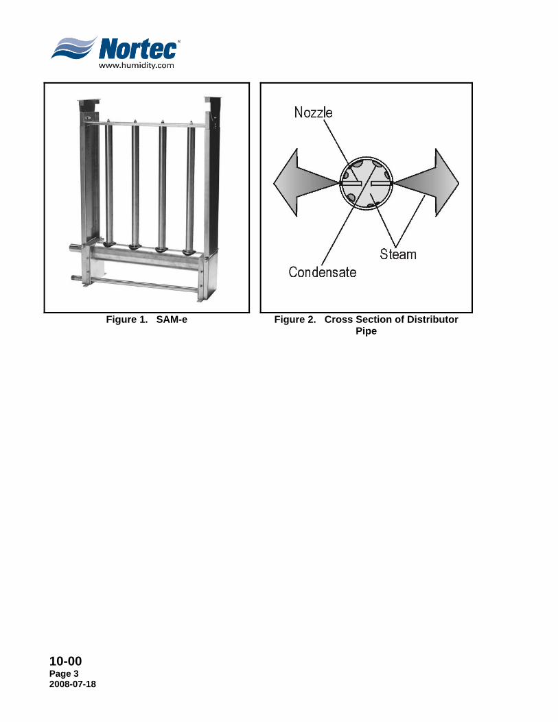
(2) The SAM-e distributes clean steam, precisely controlled, uniformly into the entire air stream, void of any condensate spray. Steam distribution takes place via distributor tubes with integrated nozzles. The steam is kept dry as condensate is drained through the main header.
(3) The stainless steel distribution tubes are typically mounted vertically but can also be mounted horizontally (10º slope) for vertical airflow applications. The distribution tubes come equipped with evenly spaced stainless steel nozzles providing optimum steam distribution, over the entire length of the tube.
(4) The nozzles extend into the center of the distribution tube ensuring only condensate-free steam is released. Condensate drains out of the distribution tubes, through the header, eliminating the need for jacketed tubes. A permanent bond between the nozzle and distribution tube is made when the nozzle is pressed into the tube. The nozzles and tubes have the same thermal expansion characteristics guaranteeing a permanent union. The precise manufactured orifices ensure consistent output from each nozzle.
2. FEATURES (1) Inlets/Outlets located on same side, one access point required. (2) All stainless steel distributors and nozzles ensure permanent bond. (3) Stainless steel header with rubber grommet seals for easy installation of
distribution tubes. (4) Tubes available in 409 or 304 stainless steel to fit every budget. (5) Available with optional stainless steel insulating shielding for increased energy
efficiency and decreased condensate losses. (6) Adjustable mounting frame available for quick and easy installation. (7) Available with 3", 6", 9”, or 12” center to center distributor spacing – (SAM-e). (8) Available in 3” and 6” center to center distributor spacing - (mini SAM-e). (9) Atmospheric or pressure steam source. (10) Two year limited warranty.
10-00 Page 3 2008-07-18
Figure 1. SAM-e
Figure 2. Cross Section of Distributor Pipe

10-00 Page 4
2008-07-18
THIS PAGE INTENTIONALLY LEFT BLANK

10-10 Page 5 2008-07-18
10-10 STEAM ABSORPTION

10-10 Page 6
2008-07-18
1. DETERMINING THE STEAM ABSORPTION DISTANCE NOTE
Visit www.humidity.com to download our Humidification Engineering & Loadsizing Program (H.E.L.P.) to help you calculate the absorption distance.
A. Injecting steam into the air requires a certain amount of time before the steam is absorbed completely.
B. In a moving air stream, this time results in the steam moving a fixed distance from the manifold before it is fully absorbed.
C. The absorption distance is the distance that is required for steam to be fully absorbed by the airstream. Knowing this distance is essential to ensure that unabsorbed steam does not condense on any downstream components.
D. The system should be designed to eliminate the possibility of wetting internal components by positioning the manifold in the optimum location and to use the full extent of the available distance for the steam to be absorbed.
E. Shorter absorption is not always desirable. Sizing a SAM-e to produce unnecessarily short absorption distances may result increased condensate losses and require a larger humidifier to compensate. It is important to balance available absorption distance with the capacity of the SAM-e.
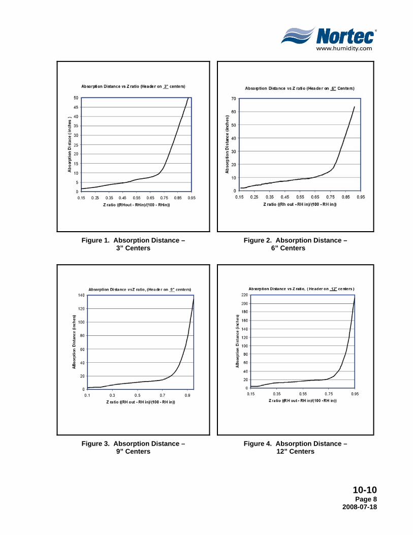
F. The absorption distance can be calculated using the Z ratio. The Z ratio and the following method may be used as a guide to calculate the absorption in various air handlers, and ducts with different conditions. It can be calculated as follows.
Z= (RHah - RHbh)
(100 - RHbh)
RHah = Percentage of relative humidity after humidification. RHbh = Percentage of relative humidity before humidification.
Example:
• 55ºF (12.8ºC)/ 12% RH - Conditions before humidification.
• 20000 CFM (33980 m3 /h)
• 400 lbs/hr (181 kg/hr) load
Using the H.E.L.P. Software or a psychometric chart you can find that the humidity conditions after adding 400 lbs/hr (181 kg/h) of steam, are 55ºF (12.8ºC) 61% rh.
Thus giving:
RHbh = 12% RHah = 61%
Z= (61 - 12) / (100 - 12) = 0.56
Absorption Distances:
3” centers = 7” (18 cm)
6” centers = 9” (23 cm)

10-10 Page 7 2008-07-18
9” centers = 12” (31 cm)
12” centers = 18” (46 cm)
NOTE Reference the Figure 1 through 4 to determine the center to center spacing required.
G. Additional Information
(1) This absorption distance data is based on 55ºF (13ºC) minimum temperature before humidification.
(2) Data is based on velocities between 200 fpm (101 cm/s) and 2500 fpm (1270 cm/s).
(3) Available absorption distance: This is the distance between the SAM-e and the first obstruction (coil, elbow, damper, etc.) steam may contact. Traces of steam may pass this obstruction, but will not condense, leaving obstructions dry.
(4) The absorption distance is a function of various conditions in the duct including; duct temperatures, duct humidity levels, duct static pressures, and air flow rates. Changes in duct geometry, flow rates, or flow conditions will require a recalculation of the SAM-e performance. It is always recommended to size the SAM-e to “worst case” conditions.
10-10 Page 8
2008-07-18
Figure 1. Absorption Distance – 3” Centers
Figure 2. Absorption Distance – 6” Centers
Figure 3. Absorption Distance – 9” Centers
Figure 4. Absorption Distance – 12” Centers

10-10 Page 9 2008-07-18
2. STATIC AIR PRESSURE A. Table 1 shows the static pressure loss created by a SAM-e in various velocities.
Table 1. Air Pressure Loss in AHU / Duct
Air Velocity
fpm (cm/s)
Air Pressure Loss (inches of water column)
SAM-e Tube Spacing
3” (7.6 cm)
6” (15.2 cm)
9” (22.7 cm)
12” (30.5 cm)
500 (255) 0.01 (0.02) 0.01 (0.02)
No measurable data
750 (383) 0.03 (0.08) 0.01 (0.02)
1000 (510) 0.05 (0.013) 0.02 (0.05)
1250 (638) 0.07 (0.18) 0.03 (0.08)
1500 (765) 0.09 (0.23) 0.04 (0.10) 0.01 0.01
1750 (893) 0.10 (0.25) 0.06 (0.15) 0.01 0.01
2000 (1020) 0.12 (0.30) 0.08 (0.20) 0.01 0.01
3. CONDENSATE LOSSES A. The SAM-e will condense some of the steam generated by the NORTEC humidifiers. To
compensate for this loss in capacity, the calculated humidification load must be increased accordingly. Please refer to Table 2.
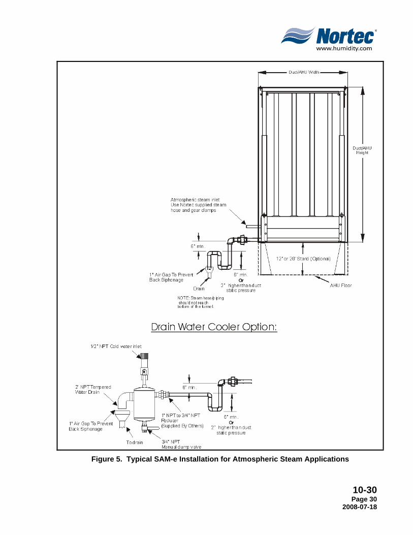
B. Nortec recommends the installation of a condensate drain on the steam line run prior to entering the SAM-e. This will prevent any condensate from the lines from entering the SAM-e.
Table 2. Condensate Loss for Uninsulated SAM-e Air Velocity fpm (cm/s)
Condensate Losses (% of Max. Cap.)
Atmos. Steam Pressurized Steam
55ºF 70ºF 55ºF 70ºF
500 (255) 15% 12% 8% 5%
1000 (510) 20% 15% 10% 7%
NOTE These values may increase or decrease due to many unknown conditions or variables. This is only a guideline.
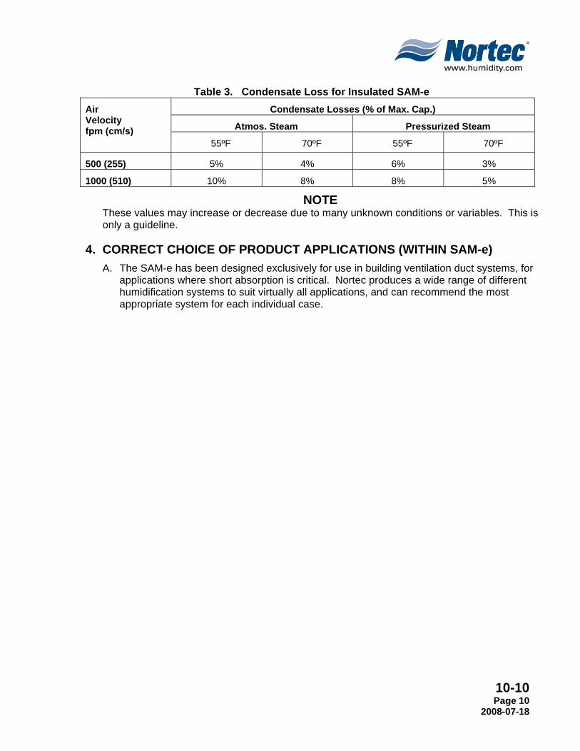
C. The SAM-e is available with optional stainless steel insulation which covers both the headers and the tubes. Insulating the SAM-e has many desirable effects including; reduced air-stream heat gain, reduced condensate losses, and improved energy efficiency. Please refer to Table 3 when estimating condensate losses with insulated SAM-e’s.
10-10 Page 10
2008-07-18
Table 3. Condensate Loss for Insulated SAM-e Air Velocity fpm (cm/s)
Condensate Losses (% of Max. Cap.)
Atmos. Steam Pressurized Steam
55ºF 70ºF 55ºF 70ºF
500 (255) 5% 4% 6% 3%
1000 (510) 10% 8% 8% 5%
NOTE These values may increase or decrease due to many unknown conditions or variables. This is only a guideline.
4. CORRECT CHOICE OF PRODUCT APPLICATIONS (WITHIN SAM-e) A. The SAM-e has been designed exclusively for use in building ventilation duct systems, for
applications where short absorption is critical. Nortec produces a wide range of different humidification systems to suit virtually all applications, and can recommend the most appropriate system for each individual case.
10-10 Page 11 2008-07-18
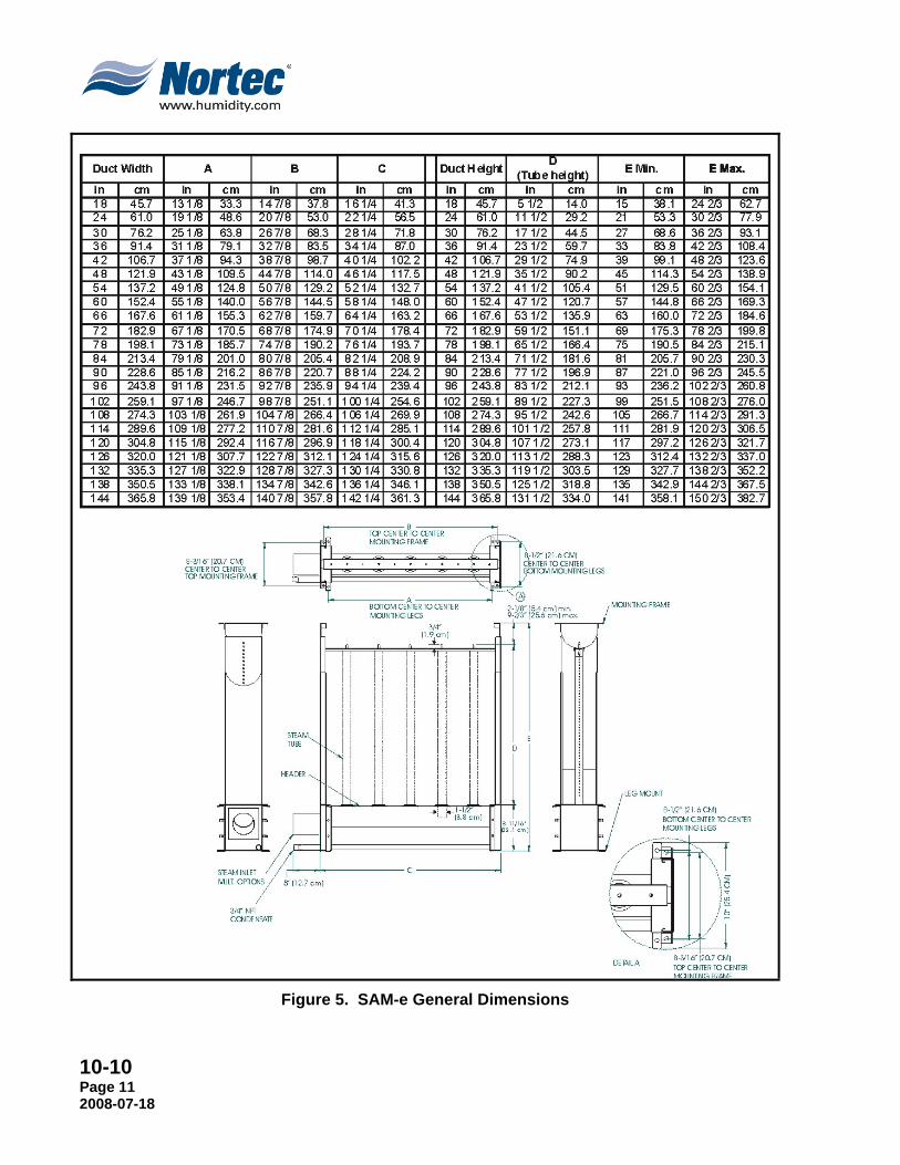
Figure 5. SAM-e General Dimensions

10-10 Page 12
2008-07-18
Figure 6. General mini SAM-e Dimensions

10-20 Page 13 2008-07-18
10-20 PRODUCT SELECTION

10-20 Page 14
2008-07-18
1. STEP 1 - SAM-E HEADER SELECTION A. NORTEC offers different ranges of manifolds to cover capacities and duct sizes. The
absorption distance and capacity required will determine the center-to-center spacing between each steam tube on the header. There are four options: 3” (7.6 cm) or 6” (15.2 cm) or 9” (22.9 cm) or 12” (30.5 cm) (mini SAM-e’s are only available with 3” and 6” spacing). The smaller the spacing, the more tubes the header can accommodate, thus giving a better absorption distance and greater capacity, at the cost of higher condensate losses.
B. The header remains the same for in-duct or outside duct mounting, for atmospheric or pressurized steam, and for vertical or horizontal flow applications.
C. Atmospheric manifolds with a capacity over 801 lbs/hr (362 kg/hr) will include a second steam inlet on the header. Consult factory submittal drawings for specific details.
D. Select the header part number associated with your duct or air handling unit’s width.
E. For example if the duct width is: 80” (198.11 cm), select part number 1503279 for 3” (7.6 cm) center to center spacing.
F. Some smaller duct sizes are too small to fit a full-size SAM-e. In these cases a mini SAM-e is used. As a rule of thumb, when duct width is less than 30” a mini SAM-e is the best choice.
G. Air Handling Unit (AHU) Installation
(1) In some LiveSteam installations where an there is no available room to install steam components such as F&T traps, separator, etc., a stand can be ordered. Stands are available in 12 or 20 inch heights, and allow traps and components to be installed into the duct along with the SAM-e. If a stand is required, the overall height of the SAM-e must be reduced by the height of the selected stand. This will enable the proper steam tube selection. As well, the width of the SAM-e should be reduced enough to allow components to fit into the duct beside the SAM-e. Please refer to the LiveSteam Engineering Manual for component sizes.
Table 1. SAM-e Stand Kits “A” Dimension Inches (cm) Part Number 12" (30.5) 1509947 20" (50.8) 1509948
NOTE
Refer to SAM-e submittal drawings for more information. All stand kits are complete with both left and right stands and required fasteners.
10-20 Page 15 2008-07-18
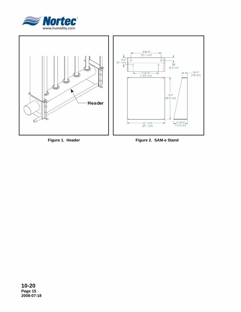
Figure 1. Header
Figure 2. SAM-e Stand

10-20 Page 16
2008-07-18
Duct Width inches (cm)
Steam Tubes Qty
Header Part
Number Max. Capacity Atmospheric Steam lbs/hr (kg/hr)
Max. Capacity Pressure Steam lbs/hr (kg/hr)
A B B+ C A B B+ C
18 (45.7) 3 1503269 45 (20) 105 (48) 165 (75) 225 (102) 45 (20) 105 (48) 165 (75) 225 (102) 24 (61.0) 5 1503270 75 (34) 175 (79) 275 (125) 375 (170) 75 (34) 175 (79) 275 (125) 375 (170) 30 (76.2) 7 1503271 105 (48) 245 (111) 385 (175) 525 (238) 105 (48) 245 (111) 385 (175) 525 (238) 36 (91.4) 9 1503272 135 (61) 315 (143) 495 (225) 675 (306) 135 (61) 315 (143) 495 (225) 675 (306)
42 (106.7) 11 1503273 165 (75) 385 (174) 605 (274) 800 (363) 165 (75) 385 (174) 605 (274) 825 (374) Double Inlet 1503291 - - 825 (374) - - - -
48 (121.9) 13 1503274 195 (88) 455 (206) 715 (324) 800 (363) 195 (88) 455 (206) 715 (324) 975 (442) Double Inlet 1503292 - - - 975 (442) - - -
54 (137.2) 15 1503275 225 (102) 525 (238) 800 (363) - 225 (102) 525 (238) 825 (374) 1125 (510) Double Inlet 1503293 - - 825 (374) 1125 (510) - - -
60 (152.4) 17 1503276 255 (116) 595 (270) 800 (363) - 255 (116) 595 (270) 935 (424) 1275 (578) Double Inlet 1503294 - - 935 (424) 1200 (544) - - -
66 (167.6) 19 1503277 285 (129) 665 (301) 800 (363) - 285 (129) 665 (301) 1045 (474) 1425 (646) Double Inlet 1503295 - - 1045 (474) 1200 (544) - - -
72 (182.9) 21 1503278 315 (143) 735 (333) 800 (363) - 315 (143) 735 (333) 1155 (524) 1575 (713) Double Inlet 1503296 - - 1155 (524) 1200 (544) - - -
78 (198.1) 23 1503279 345 (156) 800 (363) - - 345 (156) 805 (365) 1265 (574) 1745 (790) Double Inlet 1503297 - 805 (365) 1200 (544) - - - - -
84 (213.4) 25 1503280 375 (170) 800 (363) - - 375 (170) 875 (396) 1375 (624) 1875 (849) Double Inlet 1503298 - 875 (396) 1200 (544) - - - - -
90 (228.6) 27 1503281 405 (183) 800 (363) - - 405 (183) 945 (428) 1485 (674) 2025 (917) Double Inlet 1503299 - 945 (428) 1200 (544) - - - - -
96 (243.8) 29 1503282 435 (197) 800 (363) - - 435 (197) 1015 (460) 1595 (723) 2175 (985) Double Inlet 1503300 - 1015 (460) 1200 (544) - - - - -
102 (259.1) 31 1503283 465 (211) 800 (363) - - 465 (211) 1085 (492) 1705 (773) 2325 (1053)Double Inlet 1503301 - 1085 (492) 1200 (544) - - - - -
108 (274.3) 33 1503284 495 (224) 800 (363) - - 495 (224) 1155 (523) 1815 (823) 2475 (1121)Double Inlet 1503302 - 1155 (523) 1200 (544) - - - - -
114 (304.8) 35 1503285 525 (238) 800 (363) - - 525 (238) 1225 (555) 1925 (873) 2625 (1189)Double Inlet 1503303 - 1200 (544) - - - - - -
120 (304.8) 37 1503286 555 (251) 800 (363) - - 555 (251) 1295 (587) 2035 (923) 2775 (1257)Double Inlet 1503304 - 1200 (544) - - - - - -
126 (320.0) 39 1503287 585 (265) 800 (363) - - 585 (265) 1365 (618) 2145 (973) 2925 (1325)Double Inlet 1503305 - 1200 (544) - - - - - -
132 (335.3) 41 1503288 615 (279) 800 (363) - - 615 (279) 1435 (650) 2255 (1023) 3075 (1393)Double Inlet 1503306 - 1200 (544) - - - - - -
138 (350.5) 43 1503289 645 (292) 800 (363) - - 645 (292) 1505 (682) 2365 (1073) 3200 (1450)Double Inlet 1503307 - 1200 (544) - - - - - -
144 (365.8) 45 1503290 675 (306) 800 (363) - - 675 (306) 1575 (713) 2475 (1123) 3200 (1450)Double Inlet 1503308 - 1200 (544) - - - - - -
144+ (365.8) Consult Factory
Table 2. SAM-e Header – 3” Centers

10-20 Page 17 2008-07-18
Duct Width inches (cm)
Steam Tubes Qty
Header Part
Number Max. Capacity Atmospheric Steam lbs/hr (kg/hr)
Max. Capacity Pressure Steam lbs/hr (kg/hr)
A B B+ C A B B+ C
18 (45.7) 2 1503309 30 (14) 70 (32) 110 (50) 150 (68) 30 (14) 70 (32) 110 (50) 150 (68)
24 (61.0) 3 1503310 45 (20) 105 (48) 165 (75) 225 (102) 45 (20) 105 (48) 165 (75) 225 (102)
30 (76.2) 4 1503311 60 (27) 140 (63) 220 (100) 300 (136) 60 (27) 140 (63) 220 (100) 300 (136)
36 (91.4) 5 1503312 75 (34) 175 (79) 275 (125) 375 (170) 75 (34) 175 (79) 275 (125) 375 (170) 42 (106.7) 6 1503313 90 (41) 210 (95) 330 (150) 450 (204) 90 (41) 210 (95) 330 (150) 450 (204) 48 (121.9) 7 1503314 105 (48) 245 (111) 385 (175) 525 (238) 105 (48) 245 (111) 385 (175) 525 (238) 54 (137.2) 8 1503315 120 (54) 280 (127) 440 (200) 600 (272) 120 (54) 280 (127) 440 (200) 600 (272) 60 (152.4) 9 1503316 135 (61) 315 (143) 495 (225) 675 (306) 135 (61) 315 (143) 495 (225) 675 (306) 66 (167.6) 10 1503317 150 (68) 350 (159) 550 (249) 750 (340) 150 (68) 350 (159) 550 (249) 750 (340)
72 (182.9) 11 1503318 165 (75) 385 (174) 605 (274) 800 (363) 165 (75) 385 (174) 605 (274) 825 (374)
Double Inlet 1503331 - - - 825 (374) - - - -
78 (198.1) 12 1503319 180 (82) 420 (190) 660 (299) 800 (363) 180 (82) 420 (190) 660 (299) 900 (408)
Double Inlet 1503332 - - - 900 (408) - - - -
84 (213.4) 13 1503320 195 (88) 455 (206) 715 (324) 800 (363) 195 (88) 455 (206) 715 (324) 975 (442)
Double Inlet 1503333 - - 975 (442) - - -
90 (228.6) 14 1503321 210 (95) 490 (222) 770 (349) 800 (363) 210 (95) 490 (222) 770 (349) 1050 (476)
Double Inlet 1503334 - - - 1050 (476) - - - -
96 (243.8) 15 1503322 225 (102) 525 (238) 800 (363) - 225 (102) 525 (238) 825 (374) 1125 (510)
Double Inlet 1503335 - - 825 (374) 1125 (510) - - - -
102 (259.1) 16 1503323 240 (109) 560 (254) 800 (363) - 240 (109) 560 (254) 880 (399) 1200 (544)
Double Inlet 1503336 - - 880 (399) 1200 (544) - - - -
108 (274.3) 17 1503324 255 (116) 595 (270) 800 (363) - 255 (116) 595 (270) 935 (424) 1275 (578)
Double Inlet 1503337 - - 935 (424) 1200 (544) - - - -
114 (304.8) 18 1503325 270 (122) 630 (271) 800 (363) - 270 (122) 630 (271) 990 (449) 1350 (612)
Double Inlet 1503338 - - 990 (449) 1200 (544) - - - -
120 (304.8) 19 1503326 285 (129) 665 (301) 800 (363) - 285 (129) 665 (301) 1045 (474) 1425 (646)
Double Inlet 1503339 - - 1045 (474) 1200 (544) - - - -
126 (320.0) 20 1503327 300 (136) 700 (317) 800 (363) - 300 (136) 700 (317) 1100 (499) 1500 (680)
Double Inlet 1503340 - - 1100 (499) 1200 (544) - - - -
132 (335.3) 21 1503328 315 (143) 735 (333) 800 (363) - 315 (143) 735 (333) 1155 (524) 1575 (713)
Double Inlet 1503341 - - 1155 (524) 1200 (544) - - - -
138 (350.5) 22 1503329 330 (149) 770 (349) 800 (363) - 330 (149) 770 (349) 1210 (549) 1650 (748)
Double Inlet 1503342 - - 1200 (544) - - - - -
144 (365.8) 23 1503330 345 (156) 805 (365) 800 (363) - 345 (156) 805 (365) 1265 (574) 1725 (782)
Double Inlet 1503343 - - 1200 (544) - - - - -
144+ (365.8) Consult Factory
Table 3. SAM-e Header – 6” Centers

10-20 Page 18
2008-07-18
Duct Width inches (cm)
Steam Tubes Qty
Header Part
Number
Max. Capacity Atmospheric Steam lbs/hr (kg/hr) Max. Capacity Pressure Steam lbs/hr (kg/hr)
A B B+ C A B B+ C
36 (91.4) 3 1506789 45 (20) 105 (48) 165 (75) 225 (102) 45 (20) 105 (48) 165 (75) 225 (102) 48 (121.9) 5 1506790 75 (34) 175 (79) 275 (125) 375 (170) 75 (34) 175 (79) 275 (125) 375 (170) 60 (152.4) 6 1506791 105 (48) 245 (111) 385 (175) 525 (238) 105 (48) 245 (111) 385 (175) 525 (238) 72 (182.9) 7 1506792 135 (61) 315 (143) 495 (225) 675 (306) 135 (61) 315 (143) 495 (225) 675 (306) 84 (213.4) 9 1506794 165 (75) 385 (174) 605 (274) 800 (363) 165 (75) 385 (174) 605 (274) 825 (374) 96 (243.8) 10 1506795 195 (88) 455 (206) 715 (324) 800 (363) 195 (88) 455 (206) 715 (324) 975 (442)
108 (274.3) 11 1506796 225 (102) 525 (238) 800 (363) - 225 (102) 525 (238) 800 (363) 1125 (510)
Double Inlet 1506807 - - 825 (374) 1125 (510) - - - -
120 (304.8) 13 1507729 255 (116) 595 (270) 800 (363) - 255 (116) 595 (270) 800 (363) 1275 (578)
Double Inlet 1506808 - - 935 (424) 1200 (544) - - - -
132 (335.3) 14 1507730 285 (129) 665 (301) 800 (363) - 285 (129) 665 (301) 800 (363) 1425 (646)
Double Inlet 1506809 - - 1045 (474) 1200 (544) - - - -
144 (365.8) 15 1507731 315 (143) 735 (333) 800 (363) - 315 (143) 735 (333) 800 (363) 1575 (713)
Double Inlet 1507732 - - 1155 (524) 1200 (544) - - - -
144+ (365.8) Consult Factory
Table 4. SAM-e Header – 9” Centers
Duct Width inches (cm)
Steam Tubes Qty
Header Part
Number
Max. Capacity Atmospheric Steam lbs/hr (kg/hr) Max. Capacity Pressure Steam lbs/hr (kg/hr)
A B B+ C A B B+ C
36 (91.4) 3 1506797 45 (20) 105 (48) 165 (75) 225 (102) 45 (20) 105 (48) 165 (75) 225 (102) 48 (121.9) 4 1506798 60 (27) 140 (63) 220 (100) 300 (136) 60 (27) 140 (63) 220 (100) 300 (136) 60 (152.4) 5 1506799 75 (34) 175 (79) 275 (125) 375 (170) 75 (34) 175 (79) 275 (125) 375 (170) 72 (182.9) 6 1506800 90 (41) 210 (95) 330 (150) 450 (204) 90 (41) 210 (95) 330 (150) 450 (204) 84 (213.4) 7 1506801 105 (48) 245 (111) 385 (175) 525 (238) 105 (48) 245 (111) 385 (175) 525 (238) 96 (243.8) 8 1506802 120 (54) 280 (127) 440 (200) 600 (272) 120 (54) 280 (127) 440 (200) 600 (272)
108 (274.3) 9 1506803 135 (61) 315 (143) 495 (225) 675 (306) 135 (61) 315 (143) 495 (225) 675 (306) 120 (304.8) 10 1506804 150 (68) 350 (159) 550 (249) 750 (340) 150 (68) 350 (159) 550 (249) 750 (340)
132 (335.3) 11 1506805 165 (75) 385 (174) 605 (274) 800 (363) 165 (75) 385 (174) 605 (274) 825 (374) Double Inlet 1506810 - - - 825 (374) - - - -
144 (365.8) 12 1506806 180 (82) 420 (190) 660 (299) 800 (363) 180 (82) 420 (190) 660 (299) 900 (408) Double Inlet 1506811 - - - 900 (408) - - - -
144+ (365.8) Consult Factory
Table 5. SAM-e Header – 12” Centers

10-20 Page 19 2008-07-18
2. STEP 2 – STEAM TUBE SELECTION A. Constructed of 1.5” (3.81 cm) O.D. 304 (or optional 409) stainless steel tubing, the steam
tubes can accommodate duct heights between 18” (45.72 cm) - 144” (365.76 cm) for in-duct header mounting. For smaller duct applications, a mini SAM-e can accommodate sizes starting at 12” (30.5 cm) wide x 8” (20.3 cm) high. There are four types of steam tubes available, each with a different quantity of stainless steel nozzles to achieve different capacities. The nozzles draw hot, dry steam from the center of the tube, eliminating the need for jacket heating or a temperature switch. All condensate drains vertically down the walls of the tube into the main header, where it is removed through the condensate drain port. NORTEC’s unique “slip in” installation method makes for a very quick and effortless assembly.
B. Selection (1) There are 4 types of steam tubes. Each type has a different capacity, tubes are
selected to meet a load by multiplying the number of tubes for a given header spacing by their respective capacity. Ensure that the total steam tube capacity is sized to closely match the calculated load requirements, as opposed to the maximum humidifier capacity, to minimize condensate losses. (a) Type A 15 lbs/hr (7 kg/hr) (b) Type B 35 lbs/hr (16 kg/hr) (c) Type B+ 55 lbs/hr (25 kg/hr) (d) Type C 75 lbs/hr (34 kg/hr)
Figure 3. mini SAM-e Tube Insulation

10-20 Page 20
2008-07-18
Table 6. 304 Stainless Steel Tubes
*In-Duct Height
Including Header in (cm)
TYPE A 15 lbs/hr (7 kg/hr)
TYPE B 35 lbs/hr (16 kg/hr)
TYPE B+ 55 lbs/hr (25 kg/hr)
TYPE C 75 lbs/hr (34
kg/hr)
“L” Dimension
in (cm)
In-duct Optional Mounting
Frame
Outside-Duct
Optional Mounting
Frame
Steam Tube Profile
18 (45.7) 1503388 N/A N/A N/A 5.5 (14.0) 1504697 1504697
24 (61.0) 1503389 1503411 N/A N/A 11.5 (29.2) 1503469 30 (76.2) 1503390 1503412 1509391 N/A 17.5 (44.5) 1503469 36 (91.4) 1503391 1503413 1509392 1503440 23.5 (59.7)
1503470 42 (106.7) 1503392 1503414 1509393 1503441 29.5 (74.9)
1503470 48 (121.9) 1503393 1503415 1509394 1503442 35.5 (90.2)
54 (137.2) 1503394 1503416 1509395 1503443 41.5 (105.4)
60 (152.4) 1503395 1503417 1509396 1503444 47.5 (120.7)
1503471
66 (167.6) 1503396 1503418 1509397 1503445 53.5 (136.9)
1503471
72 (182.9) 1503397 1503419 1509398 1503446 59.5 (151.1)
78 (198.1) 1503398 1503420 1509399 1503447 65.5 (166.4)
84 (213.4) 1503399 1503421 1509400 1503448 71.5 (181.5)
90 (228.6) 1503400 1503422 1509401 1503449 77.5 (196.9)
96 (243.8) 1503401 1503423 1509402 1503450 83.5 (212.1)
102 (259.1) 1503402 1503424 1509403 1503451 89.5 (227.3)
1503472
108 (274.3) 1503403 1503425 1509404 1503452 95.5 (242.6)
1503472
114 (289.6) 1503404 1503426 1509405 1503453 101.5 (257.8)
120 (304.8) 1503405 1503427 1509406 1503454 107.5 (273.1)
126 (320.0) 1503406 1503428 1509407 1503455 113.5 (288.3)
132 (335.3) 1503407 1503429 1509408 1503456 119.5 (303.5)
138 (350.5) 1503408 1503430 1509409 1503457 125.5 (318.8)
144 (365.8) 1503409 1503431 1509410 1503458 131.5 (334.0)
*Add 6" to In-Duct Height for Outside-Duct Mounting of Header.

10-20 Page 21 2008-07-18
Table 7. 409 Stainless Steel Tubes *In-Duct Height
Including Header
in (cm)
TYPE A 15 lbs/hr (7 kg/hr)
TYPE B 35 lbs/hr
(16 kg/hr)
TYPE B+55 lbs/hr
(25 kg/hr)
TYPE C75 lbs/hr
(34 kg/hr)
"L" Dimension
in (cm)
In-Duct Optional Mounting
Frame
Outside-Duct
OptionalMounting
Frame
Steam Tube
Profile
18 (45.7) 2533935 N/A N/A N/A 5.5 (14.0) 1504697 1504697
24 (61.0) 2533936 2533957 N/A N/A 11.5 (29.2) 1503469 30 (76.2) 2533937 2533958 2534011 N/A 17.5 (44.5) 1503469 36 (91.4) 2533938 2533959 2534012 2533982 23.5 (59.7)
1503407 42 (106.7) 2533939 2533960 2534013 2533983 29.5 (74.9)
1503470 48 (121.9) 2533940 2533961 2534014 2533984 35.5 (90.2) 54 (137.2) 2533941 2533962 2534015 2533985 41.5 (105.4) 60 (152.4) 2533942 2533963 2534016 2533986 47.5 (102.7)
1503471
66 (167.6) 2533943 2533964 2534017 2533987 53.5 (136.9)
1503471
72 (182.9) 2533944 2533965 2534018 2533988 59.5 (151.1) 78 (198.1) 2533945 2533966 2534019 2533989 65.5 (166.4) 84 (213.4) 2533946 2533967 2534020 2533990 71.5 (181.5) 90 (228.6) 2533947 2533968 2534039 2533991 77.5 (196.9) 96 (243.8) 2533948 2533969 2534021 2533992 83.5 (212.1) 102 (274.3) 2533949 2533970 2534022 2533993 89.5 (227.3)
1503472
108 (274.3) 2533950 2533971 2534023 2533994 95.5 (242.6)
1503472
114 (289.6) 2533951 2533976 2534024 2533995 101.5 (257.8) 120 (304.8) 2533952 2533977 2534025 2533996 107.5 (273.1) 126 (320.0) 2533953 2533978 2534026 2533997 113.5 (288.3) 132 (335.3) 2533954 2533979 2534027 2533998 119.5 (303.5) 138 (350.5) 2533955 2533980 2534028 2533999 125.5 (318.8) 144 (365.8) 2533956 2533981 2534029 2534000 131.5 (334.0) *Add 6" to In-Duct Height for Outside-Duct Mounting of Header.
10-20 Page 22
2008-07-18
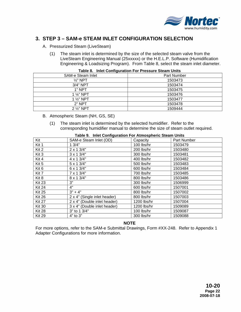
3. STEP 3 – SAM-e STEAM INLET CONFIGURATION SELECTION A. Pressurized Steam (LiveSteam)
(1) The steam inlet is determined by the size of the selected steam valve from the LiveSteam Engineering Manual (25xxxxx) or the H.E.L.P. Software (Humidification Engineering & Loadsizing Program). From Table 8, select the steam inlet diameter.
Table 8. Inlet Configuration For Pressure Steam Units SAM-e Steam Inlet Part Number
½” NPT 1503473 3/4” NPT 1503474 1” NPT 1503475
1 ¼” NPT 1503476 1 ½” NPT 1503477
2” NPT 1503478 2 ½” NPT 1509444
B. Atmospheric Steam (NH, GS, SE)
(1) The steam inlet is determined by the selected humidifier. Refer to the corresponding humidifier manual to determine the size of steam outlet required.
Table 9. Inlet Configuration For Atmospheric Steam Units Kit SAM-e Steam Inlet (OD) Capacity Part Number Kit 1 1 3/4” 100 lbs/hr 1503479 Kit 2 2 x 1 3/4" 200 lbs/hr 1503480 Kit 3 3 x 1 3/4" 300 lbs/hr 1503481 Kit 4 4 x 1 3/4" 400 lbs/hr 1503482 Kit 5 5 x 1 3/4" 500 lbs/hr 1503483 Kit 6 6 x 1 3/4" 600 lbs/hr 1503484 Kit 7 7 x 1 3/4" 700 lbs/hr 1503485 Kit 8 8 x 1 3/4" 800 lbs/hr 1503486 Kit 23 3" 300 lbs/hr 1506999 Kit 24 4" 600 lbs/hr 1507001 Kit 25 3" + 4" 800 lbs/hr 1507002 Kit 26 2 x 4" (Single inlet header) 800 lbs/hr 1507003 Kit 27 2 x 4" (Double inlet header) 1200 lbs/hr 1507004 Kit 30 3 x 4" (Double inlet header) 1200 lbs/hr 1509089 Kit 28 3" to 1 3/4" 100 lbs/hr 1509087 Kit 29 4” to 3” 300 lbs/hr 1509088
NOTE For more options, refer to the SAM-e Submittal Drawings, Form #XX-248. Refer to Appendix 1 Adapter Configurations for more information.
10-20 Page 23 2008-07-18
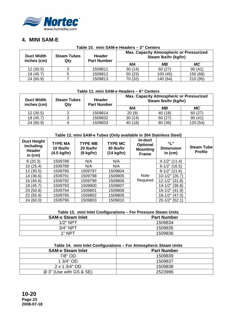
4. MINI SAM-E Table 10. mini SAM-e Headers – 3” Centers
Duct Width inches (cm)
Steam Tubes Qty
Header Part Number
Max. Capacity Atmospheric or Pressurized Steam lbs/hr (kg/hr)
MA MB MC 12 (30.5) 3 1509811 30 (14) 60 (27) 90 (41) 18 (45.7) 5 1509812 50 (23) 100 (45) 150 (68) 24 (60.9) 7 1509813 70 (32) 140 (64) 210 (95)
Table 11. mini SAM-e Headers – 6” Centers
Duct Width inches (cm)
Steam Tubes Qty
Header Part Number
Max. Capacity Atmospheric or Pressurized Steam lbs/hr (kg/hr)
MA MB MC 12 (30.5) 2 1509814 20 (9) 40 (18) 60 (27) 18 (45.7) 3 1509832 30 (14) 60 (27) 90 (41) 24 (60.9) 4 1509833 40 (18) 80 (36) 120 (54)
Table 12. mini SAM-e Tubes (Only available in 304 Stainless Steel)
Duct Height Including Header in (cm)
TYPE MA 10 lbs/hr
(4.5 kg/hr)
TYPE MB 20 lbs/hr (9 kg/hr)
TYPE MC 30 lbs/hr (14 kg/hr)
In-duct Optional Mounting
Frame
“L” Dimension
in (cm)
Steam Tube Profile
8 (20.3) 1509788 N/A N/A
Note Required
4-1/2" (11.4) 10 (25.4) 1509789 N/A N/A 6-1/2" (16.5) 12 (30.5) 1509790 1509797 1509804 8-1/2" (21.6) 14 (36.6) 1509791 1509798 1509805 10-1/2" (26.7) 16 (40.6) 1509792 1509799 1509806 12-1/2" (31.8) 18 (45.7) 1509793 1509800 1509807 14-1/2" (36.8) 20 (50.8) 1509794 1509801 1509808 16-1/2" (41.9) 22 (55.9) 1509795 1509802 1509809 18-1/2" (47.0) 24 (60.0) 1509796 1509803 1509810 20-1/2" (52.1)
Table 13. mini Inlet Configurations – For Pressure Steam Units SAM-e Steam Inlet Part Number
1/2" NPT 1509834 3/4" NPT 1509835 1" NPT 1509836
Table 14. mini Inlet Configurations – For Atmospheric Steam Units SAM-e Steam Inlet Part Number
7/8" OD 1509839 1 3/4" OD 1509837
2 x 1 3/4" OD 1509838 O 3” (Use with GS & SE) 2523996 /
10-20 Page 24
2008-07-18
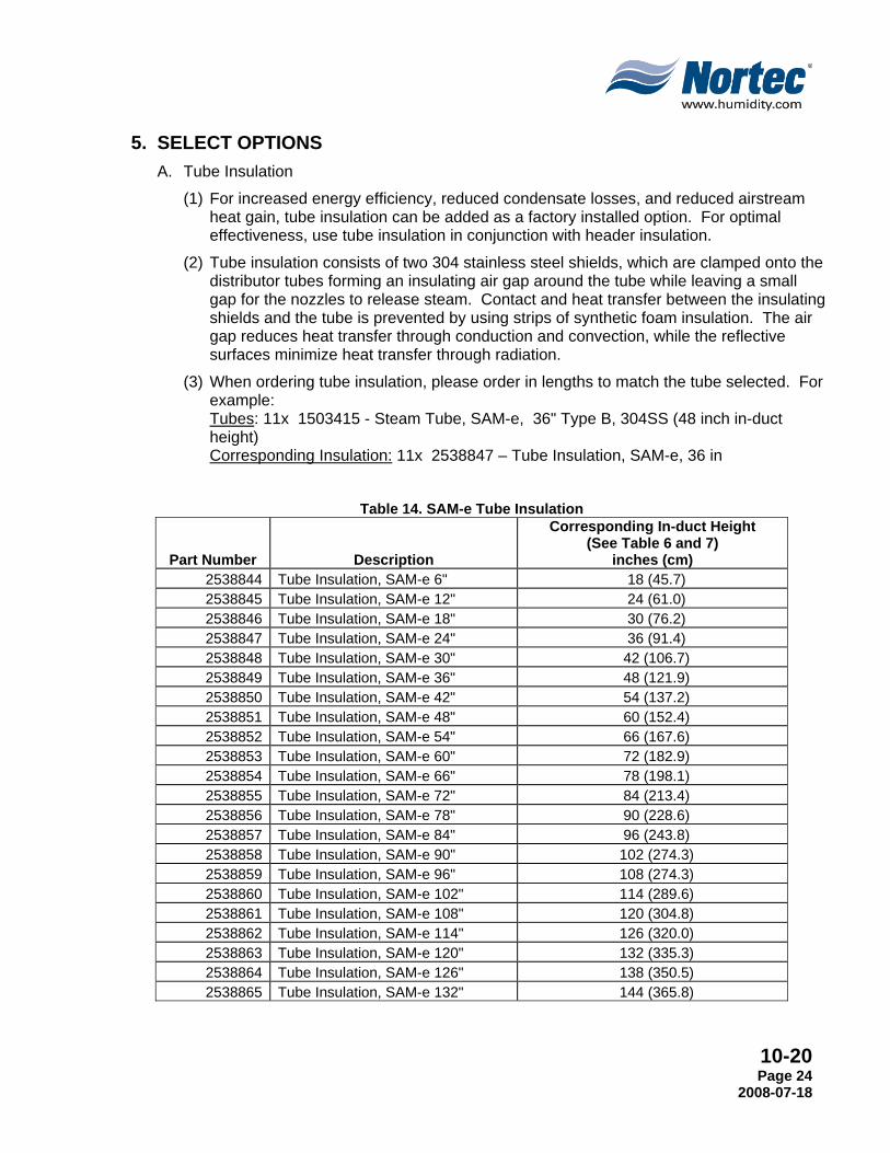
5. SELECT OPTIONS A. Tube Insulation
(1) For increased energy efficiency, reduced condensate losses, and reduced airstream heat gain, tube insulation can be added as a factory installed option. For optimal effectiveness, use tube insulation in conjunction with header insulation.
(2) Tube insulation consists of two 304 stainless steel shields, which are clamped onto the distributor tubes forming an insulating air gap around the tube while leaving a small gap for the nozzles to release steam. Contact and heat transfer between the insulating shields and the tube is prevented by using strips of synthetic foam insulation. The air gap reduces heat transfer through conduction and convection, while the reflective surfaces minimize heat transfer through radiation.
(3) When ordering tube insulation, please order in lengths to match the tube selected. For example: Tubes: 11x 1503415 - Steam Tube, SAM-e, 36" Type B, 304SS (48 inch in-duct height) Corresponding Insulation: 11x 2538847 – Tube Insulation, SAM-e, 36 in
Table 14. SAM-e Tube Insulation
Part Number Description
Corresponding In-duct Height (See Table 6 and 7)
inches (cm) 2538844 Tube Insulation, SAM-e 6" 18 (45.7) 2538845 Tube Insulation, SAM-e 12" 24 (61.0) 2538846 Tube Insulation, SAM-e 18" 30 (76.2) 2538847 Tube Insulation, SAM-e 24" 36 (91.4) 2538848 Tube Insulation, SAM-e 30" 42 (106.7) 2538849 Tube Insulation, SAM-e 36" 48 (121.9) 2538850 Tube Insulation, SAM-e 42" 54 (137.2) 2538851 Tube Insulation, SAM-e 48" 60 (152.4) 2538852 Tube Insulation, SAM-e 54" 66 (167.6) 2538853 Tube Insulation, SAM-e 60" 72 (182.9) 2538854 Tube Insulation, SAM-e 66" 78 (198.1) 2538855 Tube Insulation, SAM-e 72" 84 (213.4) 2538856 Tube Insulation, SAM-e 78" 90 (228.6) 2538857 Tube Insulation, SAM-e 84" 96 (243.8) 2538858 Tube Insulation, SAM-e 90" 102 (274.3) 2538859 Tube Insulation, SAM-e 96" 108 (274.3) 2538860 Tube Insulation, SAM-e 102" 114 (289.6) 2538861 Tube Insulation, SAM-e 108" 120 (304.8) 2538862 Tube Insulation, SAM-e 114" 126 (320.0) 2538863 Tube Insulation, SAM-e 120" 132 (335.3) 2538864 Tube Insulation, SAM-e 126" 138 (350.5) 2538865 Tube Insulation, SAM-e 132" 144 (365.8)

10-20 Page 25 2008-07-18
Table 15. mini Tube Insulation
Part Number Description
Corresponding In-Duct Height See Table 12 inches (cm)
2538866 Tube Insulation, mini SAM-e 5” 8 (20.3)
2538867 Tube Insulation, mini SAM-e 7” 10 (25.4)
2538868 Tube Insulation, mini SAM-e 9” 12 (30.5)
2538869 Tube Insulation, mini SAM-e 11” 14 (36.6)
2538870 Tube Insulation, mini SAM-e 13” 16 (40.6)
2538871 Tube Insulation, mini SAM-e 15” 18 (45.7)
2538872 Tube Insulation, mini SAM-e 17” 20 (50.8)
2538873 Tube Insulation, mini SAM-e 19” 22 (55.9)
2538874 Tube Insulation, mini SAM-e 21” 24 (60.0)
B. Header Insulation
(1) For increased energy efficiency, reduced condensate losses, and reduced airstream heat gain, header insulation can be added as a factory installed option. For optimal effectiveness, use header insulation in conjunction with tube insulation.
(2) Header insulation consists of a stainless steel shield that is clamped onto the distributor header, leaving a small gap for the steam tubes to protrude. Contact and heat transfer between the insulating shield and the tube is prevented by using strips of synthetic foam insulation. The resulting air gap around the header reduces heat transfer through conduction and convection, while the reflective surfaces minimize heat transfer through radiation.

10-20 Page 26
2008-07-18
(3) When ordering header insulation for the SAM-e, order insulation lengths to match header lengths. For example: Header: 1503316 - Header SAM-e 60", 6" centers
Insulation: 2538917 – Header Insulation, SAM-e 60” Table 16. SAM-e Header Insulation
Part Number Description
2538910 Header Insulation, SAM-e 18"
2538911 Header Insulation, SAM-e 24"
2538912 Header Insulation, SAM-e 30"
2538913 Header Insulation, SAM-e 36"
2538914 Header Insulation, SAM-e 42"
2538915 Header Insulation, SAM-e 48"
2538916 Header Insulation, SAM-e 54"
2538917 Header Insulation, SAM-e 60"
2538918 Header Insulation, SAM-e 66"
2538919 Header Insulation, SAM-e 72"
2538920 Header Insulation, SAM-e 78"
2538921 Header Insulation, SAM-e 84"
2538922 Header Insulation, SAM-e 90"
2538923 Header Insulation, SAM-e 96"
2538924 Header Insulation, SAM-e 102"
2538925 Header Insulation, SAM-e 108"
2538926 Header Insulation, SAM-e 114"
2538927 Header Insulation, SAM-e 120"
2538928 Header Insulation, SAM-e 126"
2538929 Header Insulation, SAM-e 132"
2538930 Header Insulation, SAM-e 138"
2538931 Header Insulation, SAM-e 144"

10-20 Page 27 2008-07-18
(4) When ordering header insulation for the SAM-e with an atmospheric header 801-1200 lbs per hour (dual inlet), order insulation lengths to match header lengths. For example: Header: 1503336 - Header SAM-e 102" Atmospheric 801-1200 lbs/hr, 6" centers
Insulation: 2539696 – Header Insulation 801-1200, SAM-e 108"
Table 17. Header Insulation for Atmospheric SAM-e 801-1200lbs/hr
Part Number Description
2539685 Header Insulation 801-1200, SAM-e 42"
2539686 Header Insulation 801-1200, SAM-e 48"
2539687 Header Insulation 801-1200, SAM-e 54"
2539688 Header Insulation 801-1200, SAM-e 60"
2539689 Header Insulation 801-1200, SAM-e 66"
2539690 Header Insulation 801-1200, SAM-e 72"
2539691 Header Insulation 801-1200, SAM-e 78"
2539692 Header Insulation 801-1200, SAM-e 84"
2539693 Header Insulation 801-1200, SAM-e 90"
2539694 Header Insulation 801-1200, SAM-e 90"
2539695 Header Insulation 801-1200, SAM-e 102"
2539696 Header Insulation 801-1200, SAM-e 108"
2539697 Header Insulation 801-1200, SAM-e 114"
2539698 Header Insulation 801-1200, SAM-e 120"
2539699 Header Insulation 801-1200, SAM-e 126"
2539700 Header Insulation 801-1200, SAM-e 132"
2539701 Header Insulation 801-1200, SAM-e 138"
2539702 Header Insulation 801-1200, SAM-e 144"

10-20 Page 28
2008-07-18
(5) When ordering header insulation for the mini SAM-e, order header insulation to match the length and tube spacing. For example: Header: 1509812 - Header mini SAM-e 18", 3" centers
Insulation: 2538933 – Header Insulation, mini SAM-e 18"-3 Centers
Table 17. mini SAM-e Header Insulation
Part Number Description
2538932 Header Insulation, mini SAM-e 12"-3 Centers
2538933 Header Insulation, mini SAM-e 18"-3 Centers
2538934 Header Insulation, mini SAM-e 24"-3 Centers
2539632 Header Insulation, mini SAM-e 12"-6 Centers
2539633 Header Insulation, mini SAM-e 18"-6 Centers
2539634 Header Insulation, mini SAM-e 24"-6 Centers
C. Mounting Frames
(1) Mounting frames are required for all vertical duct applications. They provide the necessary support to allow the SAM-e to be mounted in a vertical flow duct.
(2) Mounting frames may also be desirable in horizontal flow duct applications with high velocities, where additional support is desired, or where it is only possible to affix secure the SAM-e to the ceiling and floor.
(3) When ordering mounting frames, order the frames that covers a range that your SAM-e tube length (see Table 6 & 7 “Dimension L”) falls into. Mounting frames are available in galvanized and 304 stainless steel.
Table 18. SAM-e Mounting Frames
Part Number Description
1504697 Mounting Frame, SAM-e 9" to 15"
1503469 Mounting Frame, SAM-e 16" to 27"
1503470 Mounting Frame, SAM-e 28" to 51"
1503471 Mounting Frame, SAM-e 52" to 99"
1503472 Mounting Frame, SAM-e 100" to 147"
2521402 Mounting Frame, SAM-e 9" to 15", SS
2521403 Mounting Frame, SAM-e 16" to 27", SS
2521404 Mounting Frame, SAM-e 28" to 51", SS
2521405 Mounting Frame, SAM-e 52" to 99", SS
2521406 Mounting Frame, SAM-e 100" to 147", SS

10-20 Page 29 2008-07-18
D. Cover Plates
(1) Cover plates are required when mounting the header below the duct. The cover plates seal the holes around the tubes and include provisions to bolt the header to the bottom of the duct.
(2) Cover plates are ordered according to header spacing. Multiple plates are required to cover most header lengths; this is accomplished by overlapping plates as necessary.
Table 19. SAM-e Cover Plates
Part Number Description
1505419 Cover Plates, SAM-e, 3" centers 27" long
1505420 Cover Plates, SAM-e, 3" centers 51" long
1505421 Cover Plates, SAM-e, 6" centers 27 " long
1505422 Cover Plates, SAM-e, 6" centers 51" long
1508180 Cover Plates, SAM-e, 9" centers 48 " long
1508181 Cover Plates, SAM-e, 12" centers 39" long
2539853 Cover Plate, SAM-e Insulated, 3" Centers
2539854 Cover Plate, SAM-e Insulated, 6" Centers
2539855 Cover Plate, SAM-e Insulated, 9" Centers
2539856 Cover Plate, SAM-e Insulated, 12" Centers

10-20 Page 30
2008-07-18
THIS PAGE INTENTIONALLY LEFT BLANK

10-30 Page 25 2008-07-18
10-30 TYPICAL
INSTALLATION DRAWINGS

10-30 Page 26
2008-07-18
Figure 1. SAM-e Exploded View

10-30 Page 27 2008-07-18
Figure 2. SAM-e Insulated Exploded View
10-30 Page 28
2008-07-18
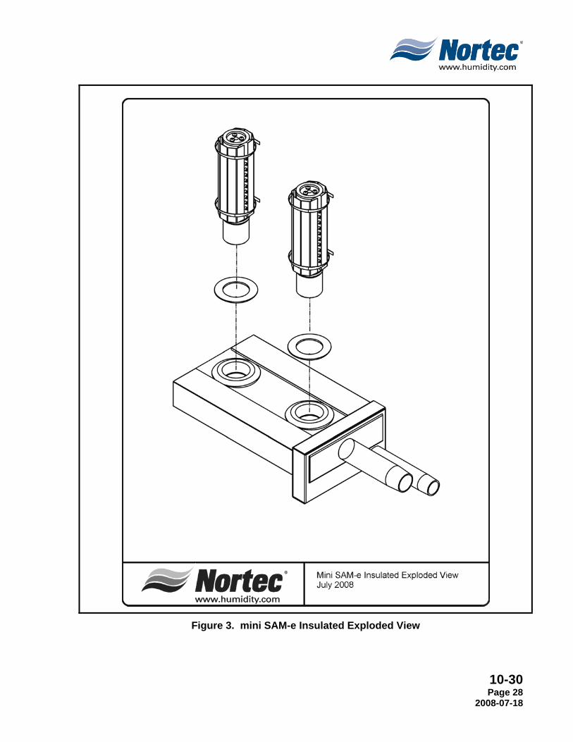
Figure 3. mini SAM-e Insulated Exploded View
10-30 Page 29 2008-07-18
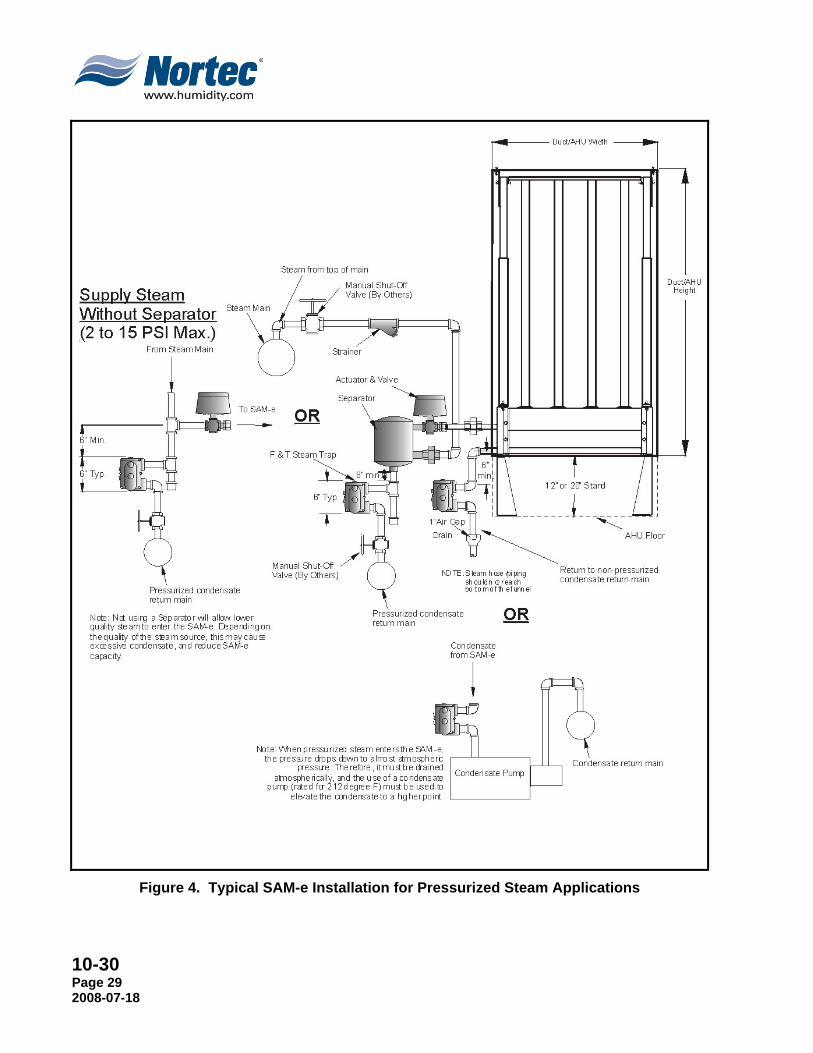
Figure 4. Typical SAM-e Installation for Pressurized Steam Applications
10-30 Page 30
2008-07-18
Figure 5. Typical SAM-e Installation for Atmospheric Steam Applications
10-30 Page 31 2008-07-18
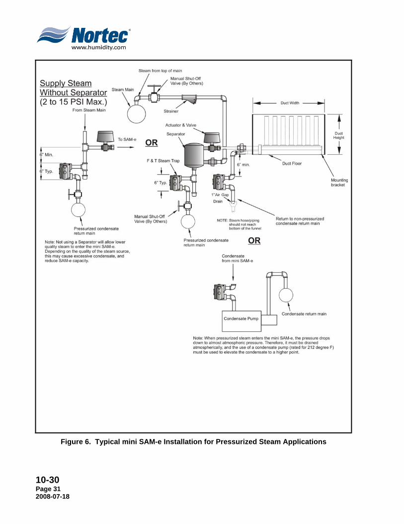
Figure 6. Typical mini SAM-e Installation for Pressurized Steam Applications

10-30 Page 32
2008-07-18
Figure 7. Typical mini SAM-e Installation for Atmospheric Steam Applications

10-40 Page 33 2008-07-18
10-40 SPECIFICATION

10-40 Page 34
2008-07-18
1. GENERAL A. Work Included
(1) NORTEC Short Absorption Manifold (Humidifier Steam Dispersion Panel) - SAM-e Humidifier[s], and mini Short Absorption Manifold (Humidifier Steam Dispersion Panel) – mini SAM-e Humidifier[s] as indicated on drawing[s] and as indicated on schedule[s].
(2) Complete and operable humidification system [which meets applicable building codes].
(3) Equipment start-up and project inspection by qualified factory trained representative.
B. Quality Assurance (1) Manufacturer: For each product specified, provide components by same
manufacturer throughout.
(2) Electrical Components, Devices, and Accessories: Listed and labeled as defined in NFPA 70, Article 100, by a testing agency acceptable to authority having jurisdiction, and marked for intended use.
(3) Comply with ARI 640, “Standard for Commercial and Industrial Humidifiers.”
(4) Products shall be supported with a warranty that ensures the product will be free from defects in materials and workmanship for a period of two years after shipment.
(5) Commissioning of a system or systems specified in this section is part of the construction process. Documentation and testing of these systems, as well as training of the Owner’s operation and maintenance personnel, is required in cooperation with the Commissioning Authority. Project Closeout is dependent on successful completion of all commissioning procedures, documentation, and issue closure. Refer to Project Closeout, Section 01700, for substantial completion details. Refer to Section 01810, Commissioning, for detailed commissioning requirements.
(6) Products specified below are to be manufactured is an ISO 9001-2000 certified facility.
C. Submittals (1) Submit product data under provisions of Section 15010. Include product
description, model, dimensions, component sizes, rough-in requirements, service sizes, and finishes. Include rated capacities, operating weights, furnished specialties, and accessories.
(2) Submit manufacturer’s installation instructions.
(3) Submit operation and maintenance data.
(4) Submit coordination drawings. Detail fabrication and installation of humidifiers. Include piping details, plans, elevations, sections, details of components, and dispersion tubes. Detail humidifiers and adjacent equipment. Show support locations, type of support, weight on each support, and required clearances.

10-40 Page 35 2008-07-18
(5) Submit wiring diagrams including power, signal, and control wiring. Differentiate between manufacturer-installed and field-installed wiring.
(6) Submit minimum water quality requirements and water pressure requirements. D. Extra Material
(1) Furnish extra materials described below that match products installed and that are packaged with protective covering for storage and identified with labels describing contents.
E. References (1) ANSI/NFPA 70 - National Electrical Code.
F. Coordination (1) Coordinate location and installation of humidifiers in ducts and air-handling units.
Revise locations and elevations to suit field conditions and to ensure proper humidifier operation.
XXXXX OR XXXXX
(2) Coordinate location and installation of humidifier in the space it serves with the electrical, mechanical, and plumbing contractors.
2. PRODUCTS A. Short Absorption Manifold
(1) Short Absorption Manifold designed for atmospheric steam humidifiers or pressurized steam from a boiler, to directly inject the steam into ducted air for humidification.
(a) Absorption distance characteristic shall prevent water accumulation on any in-duct surfaces beyond ___in (___mm) downstream of the steam dispersion panel. (Refer to distance calculated in H.E.L.P. Software).
(b) Steam dispersion panel consisting of a (one) horizontal stainless steel header supplying steam to a bank of closely spaced 3” (7.6 cm) OR 6” (15.2 cm) OR 9” (22.9 cm) OR 12” (30.5 cm) vertical tubes (3” (7.6 cm) OR 6” (15.2 cm) for mini SAM-e), as necessary to meet absorption distance requirements, and to reduce condensation losses.
(c) Single horizontal stainless steel header to provide steam to vertical distributor tubes and to reduce condensation losses. Dual header systems creating unnecessary condensation, or systems needing to be installed on a partition or requiring blank off plates are not acceptable.
(d) Header design is primarily round tube to minimize pressure drop. Square headers are not acceptable. (Full size SAM-e only).
(e) Slim profile rectangular profile header design minimizes pressure drop. (Mini SAM-e only).
10-40 Page 36
2008-07-18
(f) Steam inlet and condensate return located on the same side and at the bottom of the header to allow single point entry and floor mounting.
(g) Headers are 304 stainless steel construction.
(h) Vertical stainless steel distribution tubes to promote condensate evacuation. Horizontal distributor tubes are not accepted.
(i) Distribution tubes shall include threaded standoffs for trouble free attachment to factory supplied support bracket.
(j) All tubes are available in either 409 or 304 stainless steel construction.
(k) Stainless steel nozzle inserts ensure condensate free steam is discharged from the center of the distribution tubes. Systems without nozzle inserts, or other than stainless steel, are not acceptable.
(l) Stainless steel nozzle inserts shall have metered orifices, sized to provide even distribution of the discharged steam, spaced for optimum steam absorption.
(m) Tubes and headers shall accommodate factory installation or field retrofit of optional insulation for increased energy efficiency.
(2) Options
(a) Tube and header insulation constructed from 304 stainless steel shielding for increased energy efficiency and reduced airstream heat gain. Stainless steel shields to be isolated from distributor using plenum rated synthetic foam strips. Insulation to provide air-gap to minimize conduction and convection, as well provide reflective surface to minimize radiating heat transfer. (Patent Pending). Uninsulated headers, or simple foam insulation not accepted.
(b) Adjustable mounting frame available for quick and easy installation. (Does not apply for mini SAM-e).
(3) Standard of acceptance: Nortec SAM-e.
3. EXECUTION A. Examination
(1) Examine ducts, air-handling units, and conditions for compliance with requirements for installation tolerances and other conditions affecting performance.
(2) Examine roughing-in for piping systems to verify actual locations of piping connections before humidifier installation.
(3) Proceed with installation only after unsatisfactory conditions have been corrected.
B. Installation (1) Install humidifiers and steam dispersion panels per manufacturers’ instructions.
(2) Seal humidifier dispersion-tube duct penetrations with flange.
(3) Install with required clearance for service and maintenance.
C. Testing

10-40 Page 37 2008-07-18
(1) System verification testing is part of the commissioning process. Verification testing shall be performed by the Contractor and witnessed and documented by the Commissioning Authority. Refer to section 01810, Commissioning, for system verification tests and commissioning requirements.
XXXXX OR XXXXX
(2) Manufacturer’s Field Service: Engage a factory-authorized service representative to inspect field-assembled components and equipment installation, including piping and electrical connections. Report results in writing.
(a) Leak Test: After installation, charge system and test for leaks. Repair leaks and retest until no leaks exist.
(b) Operational Test: After electrical circuitry has been energized, start units to confirm proper unit operation. Remove malfunctioning units, replace with new units, and retest.
(c) Test and adjust controls and safeties. Replace damaged and malfunctioning controls and equipment.
D. Training (1) Training of the Owner’s operation and maintenance personnel is required in
cooperation with the Commissioning Authority. Provide competent, factory authorized personnel to provide instruction to operation and maintenance personnel concerning the location, operation, and troubleshooting of the installed systems. The instruction shall be scheduled in coordination with the Commissioning Authority after submission and approval of formal training plans. Refer to System Demonstrations, section 01670, for contractor training requirements. Refer to section 01810, Commissioning, for further contractor training requirements.
XXXXX OR XXXXX
(2) Engage a factory-authorized service representative to train Owner’s maintenance personnel to adjust, operate, and maintain humidifiers.
(a) Train Owner’s maintenance personnel on procedures and schedules for starting and stopping, troubleshooting, servicing, and maintaining equipment and schedules.
(b) Review data in maintenance manuals. Refer to Division 1 Section “Contract Closeout.”
(c) Review data in maintenance manuals. Refer to Division 1 Section “Operation and Maintenance Data.”
(d) Schedule training with Owner, through Architect, with at least seven days advance notice.
10-40 Page 38
2008-07-18
THIS PAGE INTENTIONALLY LEFT BLANK

Appendix 1 Page 39 2008-07-18
APPENDIX 1 INLET ADAPTER
CONFIGURATIONS

Appendix 1 Page 40
2008-07-18
Figure 1. KIT - Header and Adapter Configuration
Appendix 1 Page 41 2008-07-18
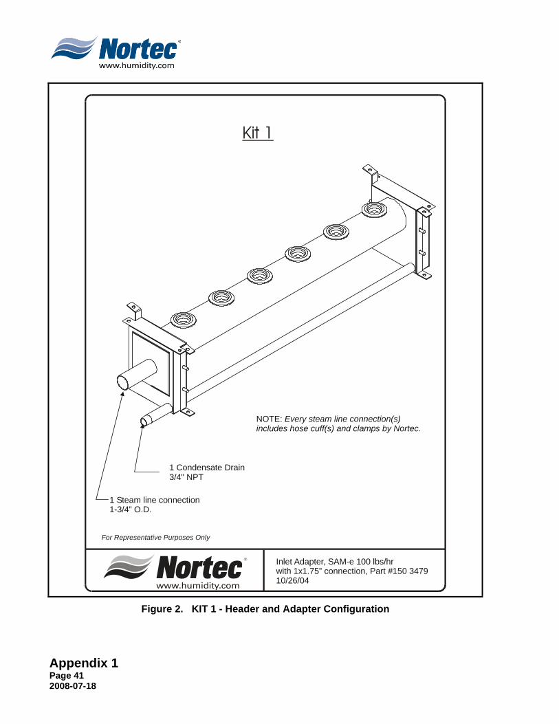
Inlet Adapter, SAM-e 100 lbs/hr with 1x1.75” connection, Part #150 347910/26/04
1 Steam line connection1-3/4” O.D.
1 Condensate Drain3/4" NPT
For Representative Purposes Only
NOTE: Every steam line connection(s)includes hose cuff(s) and clamps by Nortec.
Kit 1
Figure 2. KIT 1 - Header and Adapter Configuration
Appendix 1 Page 42
2008-07-18
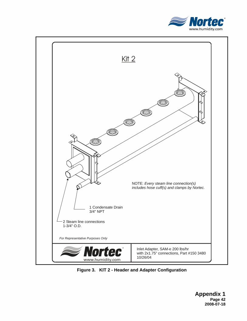
Inlet Adapter, SAM-e 200 lbs/hr with 2x1.75” connections, Part #150 348010/26/04
2 Steam line connections1-3/4” O.D.
1 Condensate Drain3/4" NPT
For Representative Purposes Only
NOTE: Every steam line connection(s)includes hose cuff(s) and clamps by Nortec.
Kit 2
Figure 3. KIT 2 - Header and Adapter Configuration

Appendix 1 Page 43 2008-07-18
Inlet Adapter SAM-e 300 lbs/hr with 3x1.75" connections, Part #150 348110/26/04
1 Condensate Drain3/4" NPT
For Representative Purposes Only
3 Steam line connections1-3/4” O.D.
NOTE: Every steam line connection(s)includes hose cuff(s) and clamps by Nortec.
Kit 3
Figure 4. KIT 3 - Header and Adapter Configuration

Appendix 1 Page 44
2008-07-18
Inlet Adapter SAM-e 400 lbs/hr with 4x1.75" connections, Part #150 348210/26/04
1 Condensate Drain3/4" NPT
For Representative Purposes Only
4 Steam line connections1-3/4” O.D.
NOTE: Every steam line connection(s)includes hose cuff(s) and clamps by Nortec.
Kit 4
Figure 5. KIT 4 - Header and Adapter Configuration

Appendix 1 Page 45 2008-07-18
Inlet Adapter SAM-e 500 lbs/hr with 5x1.75" connections, Part #150 348310/26/04
4” Hose Cuff c/w 2 Clamps
2 Condensate Drains
For Representative Purposes Only
5 Steam line connections1-3/4” O.D.
NOTE: Every steam line connection(s)includes hose cuff(s) and clamps by Nortec.
Kit 5
Figure 6. KIT 5 - Header and Adapter Configuration

Appendix 1 Page 46
2008-07-18
4” Hose Cuff c/w 2 Clamps
Inlet Adapter SAM-e 600 lbs/hr with 6x1.75" connections, Part #150 348410/26/04
For Representative Purposes Only
2 Condensate Drains3/4” NPT (Not Shown)
6 Steam line connections1-3/4” O.D.
NOTE: Every steam line connection(s)includes hose cuff(s) and clamps by Nortec.
Kit 6
Figure 7. KIT 6 - Header and Adapter Configuration
Appendix 1 Page 47 2008-07-18
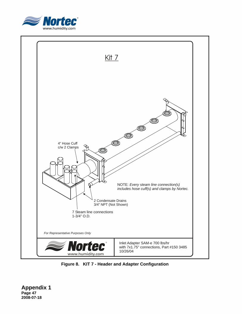
4” Hose Cuff c/w 2 Clamps
Inlet Adapter SAM-e 700 lbs/hr with 7x1.75" connections, Part #150 348510/26/04
For Representative Purposes Only
2 Condensate Drains3/4” NPT (Not Shown)
7 Steam line connections1-3/4” O.D.
NOTE: Every steam line connection(s)includes hose cuff(s) and clamps by Nortec.
Kit 7
Figure 8. KIT 7 - Header and Adapter Configuration

Appendix 1 Page 48
2008-07-18
4” Hose Cuff c/w 2 Clamps
Inlet Adapter SAM-e 800 lbs/hr with 8x1.75" connections, Part #150 348610/26/04
For Representative Purposes Only
2 Condensate Drains3/4” NPT (Not Shown)
8 Steam line connections1-3/4” O.D.
NOTE: Every steam line connection(s)includes hose cuff(s) and clamps by Nortec.
Kit 8
Figure 9. KIT 8 - Header and Adapter Configuration
Appendix 1 Page 49 2008-07-18
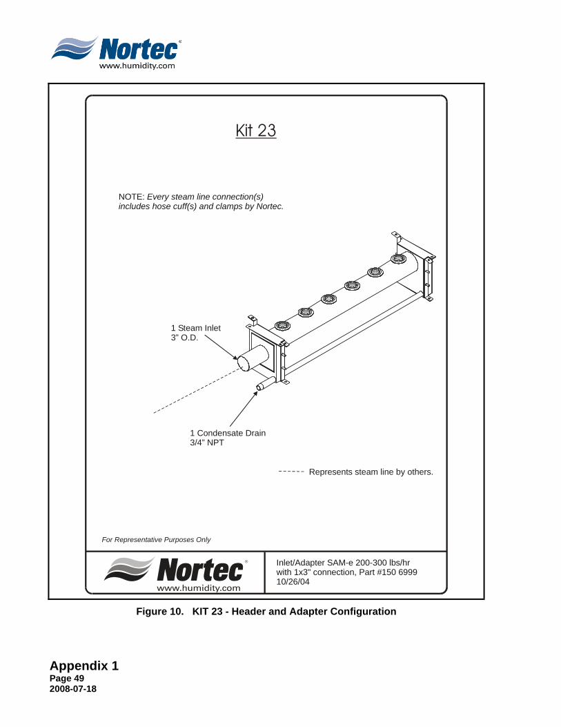
Inlet/Adapter SAM-e 200-300 lbs/hr with 1x3" connection, Part #150 699910/26/04
For Representative Purposes Only
1 Condensate Drain3/4” NPT
1 Steam Inlet3” O.D.
Represents steam line by others.
NOTE: Every steam line connection(s)includes hose cuff(s) and clamps by Nortec.
Kit 23
Figure 10. KIT 23 - Header and Adapter Configuration

Appendix 1 Page 50
2008-07-18
Inlet Adapter SAM-e 400 - 600 lbs/hr with 1x4" connection, Part #150 700110/26/04
For Representative Purposes Only
Condensate Drain3/4” NPT
Steam Inlet4” O.D.
Represents steam line by others.
NOTE: Every steam line connection(s)includes hose cuff(s) and clamps by Nortec.
Kit 24
Figure 11. KIT 24 - Header and Adapter Configuration
Appendix 1 Page 51 2008-07-18
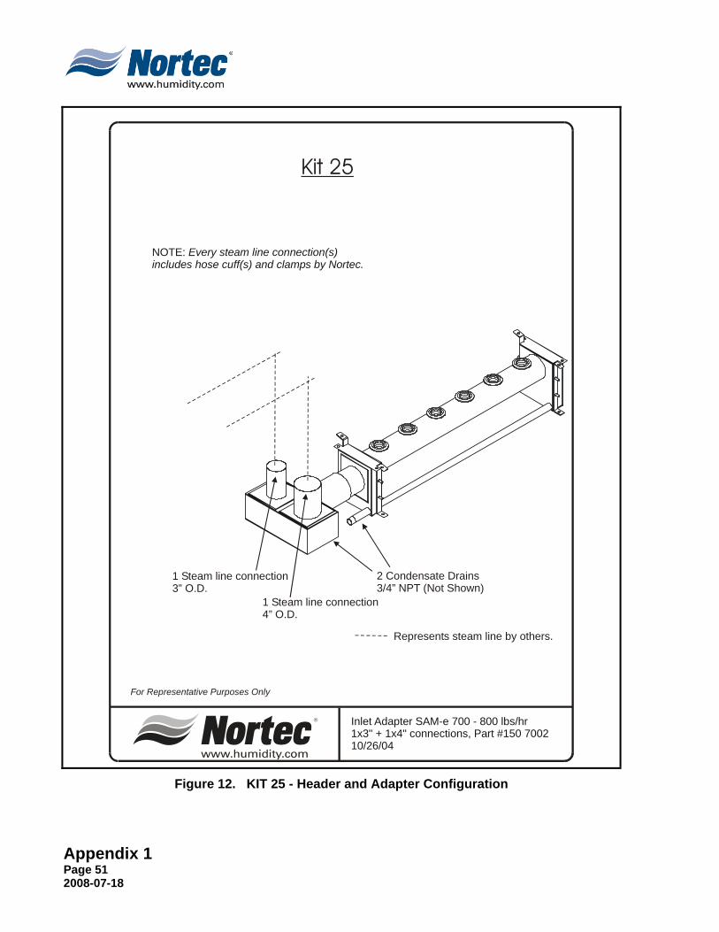
Inlet Adapter SAM-e 700 - 800 lbs/hr 1x3" + 1x4" connections, Part #150 700210/26/04
1 Steam 3” O.D.
line connection
1 Steam 4” O.D.
line connection
For Representative Purposes Only
2 Condensate Drains3/4” NPT (Not Shown)
Represents steam line by others.
NOTE: Every steam line connection(s)includes hose cuff(s) and clamps by Nortec.
Kit 25
Figure 12. KIT 25 - Header and Adapter Configuration
Appendix 1 Page 52
2008-07-18
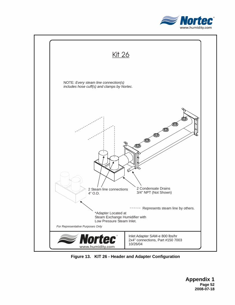
Inlet Adapter SAM-e 800 lbs/hr 2x4" connections, Part #150 700310/26/04
2 Steam 4” O.D.
line connections
For Representative Purposes Only
2 Condensate Drains3/4” NPT (Not Shown)
Represents steam line by others.
NOTE: Every steam line connection(s)includes hose cuff(s) and clamps by Nortec.
Kit 26
*Adapter Located at Steam Exchange Humidifier withLow Pressure Steam Inlet.
Figure 13. KIT 26 - Header and Adapter Configuration

Appendix 1 Page 53 2008-07-18
Inlet Adapter SAM-e 801-1200 lbs/hr with 2x4" connections, Part #150 700410/26/04
2 Steam 4” O.D.
line connections
For Representative Purposes Only
Condensate Drain3/4” NPT
Represents steam line by others.
NOTE: Every steam line connection(s)includes hose cuff(s) and clamps by Nortec.
Kit 27
Figure 14. KIT 27 - Header and Adapter Configuration
Appendix 1 Page 54
2008-07-18
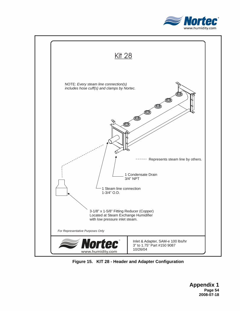
Inlet & Adapter, SAM-e 100 lbs/hr Part #150 9087
10/26/043” to 1.75”
1 Steam line connection1-3/4” O.D.
1 Condensate Drain3/4" NPT
For Representative Purposes Only
3-1/8” x 1-5/8” Fitting Reducer (Copper)Located at Steam Exchange Humidifier with low pressure inlet steam.
Represents steam line by others.
NOTE: Every steam line connection(s)includes hose cuff(s) and clamps by Nortec.
Kit 28
Figure 15. KIT 28 - Header and Adapter Configuration
Appendix 1 Page 55 2008-07-18
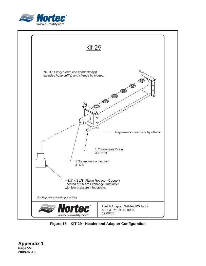
Inlet & Adapter, SAM-e 300 lbs/hr 4” to 3” Part #150 908812/08/05
1 Steam line connection3” O.D.
1 Condensate Drain3/4" NPT
For Representative Purposes Only
4-1/8” x 3-1/8” Fitting Reducer (Copper)Located at Steam Exchange Humidifierwith low pressure inlet steam.
Represents steam line by others.
NOTE: Every steam line connection(s)includes hose cuff(s) and clamps by Nortec.
Kit 29
Figure 16. KIT 29 - Header and Adapter Configuration
Appendix 1 Page 56
2008-07-18
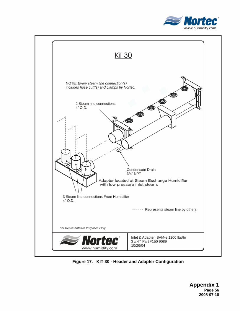
Inlet & Adapter, SAM-e 1200 lbs/hr 3 x 4”” Part #150 908910/26/04
For Representative Purposes Only
Represents steam line by others.
3 Steam 4” O.D.
line connections From Humidifier
2 Steam 4” O.D.
line connections
Condensate Drain3/4” NPT
NOTE: Every steam line connection(s)includes hose cuff(s) and clamps by Nortec.
Kit 30
Figure 17. KIT 30 - Header and Adapter Configuration

Appendix 1 Page 57 2008-07-18
THIS PAGE INTENTIONALLY LEFT BLANK

WARRANTY(1) WALTER MEIER INC. and/or WALTER MEIER LTD. (hereinafter collectively referred
to as THE COMPANY), warrant for a period of two years after installation or 30 months from manufacturer’s ship date, whichever date is earlier, that THE COMPANY’s manufactured and assembled products, not otherwise expressly warranted (with the exception of the cylinder), are free from defects in material and workmanship. No warranty is made against corrosion, deterioration, or suitability of substituted materials used as a result of compliance with government regulations.
(2) THE COMPANY’s obligations and liabilities under this warranty are limited to furnishing replacement parts to the customer, F.O.B. THE COMPANY’s factory, providing the defective part(s) is returned freight prepaid by the customer. Parts used for repairs are warranted for the balance of the term of the warranty on the original humidifier or 90 days, whichever is longer.
(3) The warranties set forth herein are in lieu of all other warranties expressed or implied by law. No liability whatsoever shall be attached to THE COMPANY until said products have been paid for in full and then said liability shall be limited to the original purchase price for the product. Any further warranty must be in writing, signed by an officer of THE COMPANY.
(4) THE COMPANY’s limited warranty on accessories, not of the companies manufacture, such as controls, humidistats, pumps, etc. is limited to the warranty of the original equipment manufacturer from date of original shipment of humidifier.
(5) THE COMPANY makes no warranty and assumes no liability unless the equipment is installed in strict accordance with a copy of the catalog and installation manual in effect at the date of purchase and by a contractor approved by THE COMPANY to install such equipment.
(6) THE COMPANY makes no warranty and assumes no liability whatsoever for consequential damage or damage resulting directly from misapplication, incorrect sizing or lack of proper maintenance of the equipment.
(7) THE COMPANY retains the right to change the design, specification and performance criteria of its products without notice or obligation.
INSTALLATION DATE (MM/DD/YYYY)
MODEL #
SERIAL #
U.S.A.Walter Meier (Climate USA) Inc.826 Proctor AvenueOgdensburg, NY 13669TEL: 1-866-NORTEC-1EMAIL: [email protected]: www.humidity.com
CANADAWalter Meier (Climate Canada) Ltd.2740 Fenton RoadOttawa, ON K1T 3T7TEL: 1-866-NORTEC-1FAX: (613) 822-7964
Authorized Agent: