salt lake city, utah 84112 integrated oxygen production ... library/events/2017/co2...
TRANSCRIPT

155 South 1452 East Room 380 Salt Lake City, Utah 84112 1-801-585-1233
Project DE-FE0025076
Kevin J. Whitty and JoAnn S. Lighty*
The University of Utah*Now at Boise State University, Idaho
Integrated Oxygen Production and CO2Separation through Chemical Looping Combustion with Oxygen Uncoupling
2017 NETL CO2 Capture Technology Project Review MeetingPittsburgh, PA
August 21-25 2017

2
Outline
Project overview
Technology background
Technical approach / project scope
Progress and current status of project
Future plans

3
Project Overview
Participants:
Source University of Utah Amaron Energy TOTAL
DOE $ 1,597,665 $ 282,655 $ 1,880,320
Cost share $ 399,416 $ 70,664 $ 470,080
TOTAL $ 1,997,081 $ 353,319 $ 2,350,400
AmaronEnergy
Funding:
Project Dates: September 1, 2015 – September 30, 2018
Objectives: Advance chemical looping combustion with oxygen uncoupling (CLOU) technology to pilot scale (NETL TRL 5) through system scale-up, operation of a 200 kW process development unit, process modeling and reactor simulation

4
Technology Background: Chemical Looping Combustion (CLC)
CLC achieves in situ air separation by using a metal to transport oxygen from air reactor to fuel reactor
Fuel (e.g. natural gas, coal) fed to fuel reactor is indirectly combusted by oxygen on oxidized metal
Metal returns to reduced state in fuel reactor and “loops” back to air reactor
Overall balance same as for conventional combustion
Economic evaluations indicate CLC yields lowest COE of any CO2-capture technology
Air
H2OCO2O2-depleted air
Reducedmetal
Steam/CO2
Oxidizedmetal
Fuelreactor
Airreactor
Fuel(CxHy)
CO2
H2O
4
5
6
7
8
9
0 10 20 30 40 50
Without Capture
IGCC
MEA
Oxy-fuel
Oxygen trans. membrane
Chemical looping
Chilled Ammonia
Cos
t of E
lect
ricity
(cen
ts/k
Wh)
Cost of CO2 ($/ton)
(Marion, 2004)

5
Technology Background: Fundamental ScienceChemical Looping with Oxygen Uncoupling (CLOU)
Copper is one of few metals for which oxidation equilibrium (Cu2O/CuO) lies within CLC operating temperatures.
Cu 2O is oxidized in air reactor
CuO spontaneously releases O 2in fuel reactor due to low O2partial pressure
Released O 2 reacts with solid coal char, converting more than 50x faster than with non-CLOU oxygen carriers
Air Reactor Fuel Reactor
2 Cu2O + O2 ➙ 4 CuO
4 CuO ➙ 2 Cu2O + O2
C + O2 ➙ CO2(EXOthermic)
(ENDOthermic)
(EXOthermic)
CuO
Cu2OC + 4 CuO ➙ 2 Cu2O + CO2
(EXOthermic)
N2, O2
Air
CO2, H2O
Steam + Coal (C)
Cu2O(s) + ½ O2(g) ⇄ 2 CuO(s)

6
Technology Background: Previous R&D at University of Utah
CLC intensively researched worldwideUofU researching since • 2007
Oxygen carrier developmentFocus on • inexpensive copper-based carrierswith scalable productionDozens of alternatives tested•Baseline • is CuO-on-SiC/SiO2
Reactor and process developmentFundamental studies of CLOU reaction•kineticsLab• -scale experiments of coal conversionDesign and • preparation of 200 kW PDU
Process modeling and reactor simulationAspen Plus modeling of CLC system•Barracuda VR® modeling of integrated•fluidized bed system
0
0.1
0.2
0.3
0.4
0.5
0.6
0.7
0.8
0.9
1
0 10 20 30 40 50 60
Conv
ersi
on
Time (minutes)
750775800825850875900925950
0
0.2
0.4
0.6
0.8
1
0 1 2 3 4 5Time (minutes)
FUEL-REA
DECOMPBURN
GAS-SOL1
AIR-REAC
GAS-SOL2
AIR-COOL
GAS-SOL3
LOSS
GAS-COOL
CUO-HEAT
AIR-HEATAIR-COMP
REC-COMP
SPLITTER
REC-HEAT
IN-CUO
COAL
Q-FUEL
INBURN
HOT-COMB
Q-DECOMP
Q-BURNQ
CU-SOL
O2
AIR
ARX-PROD
Q-AIRQ
CUO-REC
AIR-OUT
COLD-AIR
Q-EXHAUS
Q
ASH
COMB-GAS
CU-SOL2
Q
COLD-GAS
Q
HOT-CUO
Q-CUO
Q
Q-AIRHOTQ
HOT-AIR
COMBPURG
RECYCLE
FAST-AIR
FAST-REC
HOT-REC
Q-RECYC
Q

7
Technology Background: Advantages and Challenges of CLOU
Advantages• CLOU can convert coal char up to 50 times faster than conventional CLC
- Carbon conversion > 99.9% has been achieved in bench-scale tests- CO2 capture > 99% has been achieved in bench-scale tests- High conversion in fuel reactor eliminates need for carbon stripper
• Fast reactions reduce reactor size and oxygen carrier inventory• High conversion and CO2 capture improves economics
Challenges• Operation of dual fluidized bed
- Circulation, temperature control, particle retention• Oxygen carrier production
- Balance copper availability, reactivity, physical strength • CLOU carriers are comparatively expensive
- Physical robustness and retaining activity are especially important

8
Technical Approach
Three major research areasScale up of CLOU oxygen carrier 1.productionCLOU Experiments2.
200 – kW PDU10 – kW bench-scale
System modeling and reactor 3.simulation
Performance targetsCO• 2 capture (target min. 90%)CO• 2 purity (target min. 95%)Coal conversion (target min. • 99%)
Work plan / TasksProject management1.
Construction of pilot2. -scale rotary kiln for oxygen carrier production
Complete construction/initial testing of 3.pilot-scale CLC system
Evaluation of carbon conversion in CLOU 4.environment
CLOU system modeling5.
Production and characterization of CLOU 6.carrier particles
Evaluation of CLOU performance and CO7. 2capture at pilot scale
Carbon stripper 8. design and modeling
Design 9. of pilot/demo scale CLOU reactors
✔
✔
✔
9
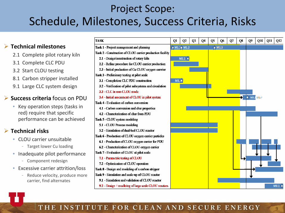
Project Scope:Schedule, Milestones, Success Criteria, Risks
Technical milestones2.1 Complete pilot rotary kiln3.1 Complete CLC PDU3.2 Start CLOU testing8.1 Carbon stripper installed9.1 Large CLC system design
Success criteria focus on PDUKey operation steps (tasks in •red) require that specific performance can be achieved
Technical risksCLOU carrier unsuitable•
Target lower Cu loading-Inadequate pilot performance•
Component redesign-Excessive carrier attrition/loss•
Reduce velocity, produce more -carrier, find alternates

10
Progress and Current Status:Scale-up of CLOU Oxygen Carrier Production
Equipment0.1 • kg lab scale rotovap1 • kg lab scale10 • kg bench scale100 • kg pilot built (Amaron)
ManufactureWet or dry impregnation•Support material is key•
strong-inert-reasonable surface area-
Complexes and stabilizers•Calcining•
nitrate decomposition-
System Type Capacity Heating Max T Length Diam
RV-1 Rotary evap 1 kg Water bath 95°C n/a 0.15 m
RK-1 Rotary kiln 1 kg Elec Inductive 800°C 0.15 m 0.1 m
RK-10 Rotary kiln 10 kg Elec radiative 350°C 0.8 m 0.2 m
RK-100 Rotary kiln 100 kg Natural gas 500°C 1.4 m 0.4 m
RK-100 oxygen carrier production kiln
RK-10 bench-scale rotary kiln
RK-1 lab-scale induction kiln

11
Progress and Current Status:Improvement of CLOU Oxygen Carriers
StatusOver • 55 carriers testedBaseline support: SiC•
cheap but poor Cu distribution-New supports: SiO• 2, MgAl2O4
also with stabilizers-Test • batches of 50 kg producedGood • cyclability in small fluid bed
CharacterizationTGA: oxygen • loading/ratesBET: surface • areaSEM: morphology, Cu distribution•Crush strength•Lab• -scale fluidized bed for long-term performance in a cycling fluidized bed reactor
Lab-scale fluidized bed system
Silica support 1 addition 1 addition calcined 2 additions calcined

12
Progress and Current Status:CLOU Experiments and Process Development
10 kW Bench ScaleApprox• 1.5 kg/hrTwo bubbling beds•All electrically heated•Screening studies•
200 kW PDUTwo interconnected • CFBs0.25• m ID, 5m tallAir for AR, steam for FR•Refractory• -linedElectric + gas • air/steam preheatApprox. • 175 kg bed inventoryBaghouse filters•

13
Preliminary testingCold flow circulation rates•Hot flow circulation rates•Ilmenite as oxygen carrier•
Operation progressionCLC of natural gas•
ilmenite-Cu- -on-Al2O3
iG• -CLC of coalilmenite-Cu- -on-Al2O3
CLOU of coal•CLOU carrier-
Progress and Current Status:PDU Operation

14
Progress and Current Status:PDU Operational Experience
StatusConstruction • completeShakedown complete•
Gas flow + preheat-Controllable coal feed-Circulation rates > - 10 ton/hr
Over • 600 hours of hot circulationTemps to • 1700°F achieveOperators comfortable•
ChallengesPreheat•
electric, burners, propane, -nat gas
Cyclones and bed loss•Geometry - vs wall roughnessLoop seal operation-Loop seal sensors-Particle size-
“Normal” things•Leaks, etc.-

15
Progress and Current Status:Process Modeling and Simulation
Experimental modeling • Plexiglas cold flow system• Scaled properly to represent
PDU• 60% scale• Air for fluidization• Glass beads• Pressure profiles• Circulation rates
Computational simulation• CPFD Barracuda VR®
Cold-flow model of UofU PDU

16
Progress and Current Status:Chemical Looping Reactor Simulation
Models of 10 kW bench-scale, 200 kW pilot-scale reactors, and cold-flow unitSimulations include
hydrodynamics•heat transfer•Chemistry/kinetics•
Oxygen carrier-Coal combustion -Gas phase -
Understanding from simulations valuable for interpreting behavior of pilot-scale system

1

18
Progress and Current Status:Significant Accomplishments
Successful scale -up of CLOU oxygen carrier productionCan now produce enough material for PDU operation•Initial batches of well• -performing carrier to 20% CuO loading produced
Successful commissioning of 200 kW PDUAll systems now function properly•Measured oxygen carrier circulation rates exceed design•Already • 600+ hours of hot operation with circulationInitial CLC experience with natural gas•
Successful development of PDU simulation modelIncorporation of kinetics for oxygen carrier reactions•Incorporation and improvement of coal combustion reaction kinetics•Over • 50 different conditions have been simulated, each with at least 60 seconds of operation

19
Future Plans
This projectContinue improving CLOU carrier performance•
Improve physical and chemical stability-Eventually target - 50+ % CuO to increase load
Parametric testing of PDU with CuO (CLOU) carrier and coal•Vary coal, coal particle size, air reactor flow rate (circulation rate), -Measure CO- 2 capture, CO2 purity, fuel conversion, overall performanceDesign, install and test carbon stripper to improve coal conversion and -CO2 capture.
Advance computational simulation•Validate simulation of PDU with operational data-Simulate larger (e.g. - 10 and 100 MW) reactors
Future developmentContinued operation and experience with PDU•Pursue opportunities for larger pilot (• 3-10 MW) system
20
Acknowledgments
This material is based upon work supported by the Department of Energy under Award DE-FE0025076.
University of Utah Chemical Looping team
Amaron Energy
Disclaimer: This presentation was prepared as an account of work sponsored by an agency of the United StalesGovernment. Neither the United States Government nor any agency thereof, nor any of their employees, makes anywarranty, express or implied, or assumes any legal liability or responsibility for the accuracy, completeness, orusefulness of any information, apparatus, product, or process disclosed, or represents that its use would not infringeprivately owned rights. Reference herein to any specific commercial product, process, or service by trade name,trademark, manufacturer, or otherwise docs not necessarily constitute or imply its endorsement, recommendation, orfavoring by the United States Government or any agency thereof. The views and opinions of authors expressed hereindo not necessarily state or reflect those of the United States Government or any agency thereof.

Please join us in 2018 at the 5th International
Chemical Looping ConferencePark City, Utah
24-27 September 2018