[email protected] † owner's manual manual.pdf · move the crusher to its installation...
TRANSCRIPT

Vestil Manufacturing Corporation2999 North Wayne Street, P.O. Box 507
Angola, Indiana 46703 USAPhone (260) 665-7586 • Fax (260) 665-1339
[email protected] • www.vestil.com
Revised 06/15
A company dedicated to solving ergonomic and materialhandling problems since 1955.
OWNER'SMANUALHYDRAULIC DRUM CRUSHER/COMPACTOR MODELS HDC-900 & HDC-905
WARNINGS & SAFETY INSTRUCTIONSRead owner's manual completely before operating unit!• Do not service unit unless power is disconnected.• Do not operate drum crusher/compactor unless all cover
plates are in place and all components are in proper workingorder.
• Do not clean out drum crusher unless power isdisconnected.
• Do not bypass the safety interlocks.• Keep hands and feet outside the unit at all times when
operating.• Do not allow personnel to stand on drum crusher.• Do not stand in front of drum crusher door.• Do not operate this unit with loading door open. **(Do not
operate if safety switch is not functioning properly.)• Do not change pressure relief valve setting.• Do not clamp hydraulic cylinder in a vise as you may distort
the drum.• Use only maintenance parts either supplied or approved by
the manufacturer.•
DO NOT modify the drum crusher in any way without firstobtaining written authorization from VESTIL.Unauthorized modification(s) automatically void theLimited Warranty and might make the crusher unsafe touse.
•
Do not use brake fluids or jack oils. Use AW-32 Hydraulicoil or equal.
• Report all safety problems immediately.•
Make sure all labels (see Label placement diagram, p. 12)and machine guards are in place & readable or functioning.
HYDRAULIC DRUM CRUSHER/COMPACTOR MODELS HDC-900 & HDC-905
ContentsWarnings and Safety Instructions..................... 1Receiving Instructions ...................................... 1Warnings and Safety Instructions..................... 2Operating Instructions ...................................... 3Installation Instructions ..................................... 4Loading Instructions ......................................... 4Periodic Maintenance Instructions ................... 5Exploded Parts Drawings....................... 6A & 6BBills of Materials..................................... 6A & 6B
Power Unit: Diagram & Parts List .........7A-7BPressure Switch & Valve Settings..........7C-7EElectrical Circuit Diagram ............................. 8Electrical System Specifications................... 9Hydraulic Circuit Diagram........................... 10Label Placement Diagram .......................... 11Limited Warranty (Standard Units) ...........12ALimited Warranty (Wash-down Units)........12B
RECEIVING INSTRUCTIONS After delivery, IMMEDIATELY remove the packaging from the product in a manner that preserves the packaging and maintains the orientation of the product in the packaging; then inspect the product closely to determine whether it sustained damage during transport. If damage is discovered during the inspection, immediately record a complete description of the damage on the bill of lading. If the product is undamaged, discard the packaging.
SERIAL NUMBER AND CAPACITY The serial number and capacity are inscribed on the nameplate (See p. 12 for location). Please remember to include these numbers in any correspondence with your dealer or the factory.
ENGLISH
ESPANOL
FRANÇAIS
Page 1
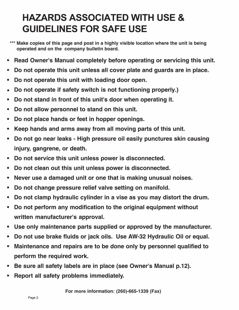
HAZARDS ASSOCIATED WITH USE & GUIDELINES FOR SAFE USE
*** Make copies of this page and post in a highly visible location where the unit is being operated and on the company bulletin board.
For more information: (260)-665-1339 (Fax)
• Read Owner's Manual completely before operating or servicing this unit.
• Do not operate this unit unless all cover plate and guards are in place.
• Do not operate this unit with loading door open.
Do not operate if safety switch is not functioning properly.)
• Do not stand in front of this unit's door when operating it.
• Do not allow personnel to stand on this unit.
• Do not place hands or feet in hopper openings.
• Keep hands and arms away from all moving parts of this unit.
• Do not go near leaks - High pressure oil easily punctures skin causing
injury, gangrene, or death.
• Do not service this unit unless power is disconnected.
• Do not clean out this unit unless power is disconnected.
• Never use a damaged unit or one that is making unusual noises.
• Do not change pressure relief valve setting on manifold.
• Do not clamp hydraulic cylinder in a vise as you may distort the drum.
• Do not perform any modification to the original equipment without
written manufacturer's approval.
• Use only maintenance parts supplied or approved by the manufacturer.
• Do not use brake fluids or jack oils. Use AW-32 Hydraulic Oil or equal.
• Maintenance and repairs are to be done only by personnel qualified to
perform the required work.
• Be sure all safety labels are in place (see Owner's Manual p.12).
• Report all safety problems immediately.
•
Page 2

OPERATING INSTRUCTIONS The HDC-900 is equipped with a momentary contact control. This relieves the operator from having
to hold the "Start" button while the unit cycles.
Sequence of Operation: To operate the crusher: 1) select the appropriate platen configuration (see "Platen configurations"
on p. 4); 2) place a drum inside the crusher; 3) close the door; 4) lock the door latch handle; 5) turn the key switch to the appropriate mode; 6) select “CRUSH” or “COMPACT”; 7) pull out the Emergency Stop button; 8) momentary press the cycle “START” button to activate the crush/compact cycle.
The direction of the platen's travel will be determined by its starting position -- if it is fully raised to the top of the cabinet, the platen will move down to crush a drum; otherwise, the cylinder will raise the platen until it finally is all the way up and in its starting ("home") position, at which point the power unit will turn off. Pressing the cycle start button again will cause the platen to move downward. The operator must hold the button for a few seconds to latch the circuit.
When the crusher is in its "home" position and the cycle start button is pressed, the cylinder pushes the platen down onto (or into) the drum. In order to achieve a short cycle time, both sections of the pump in the power unit drive oil to the cylinder until the cylinder pressure reaches approximately 1000 PSI. At that time, the higher-displacement section recycles oil to the reservoir while the low-displacement, high-pressure section continues to pump oil to the cylinder, i.e. a typical High-Low circuit.
As the platen crushes or compacts the drum to a height of about 6 inches, the cylinder pressure increases until it reaches the set-point of the appropriate pressure switch. The valve shifts to center and a timer activates to control the period of decompression. Once the period ends the directional valve shifts and reverses the direction of oil flow to the cylinder. Reversing the flow of oil raises the platen to its starting, or "home" position. When the cylinder returns the platen all the way to the top of the cabinet, the power unit turns off. At this point, the cabinet door can be opened to remove the drum.
If the unit needs to be stopped at any point during its cycle, the operator can depress the red emergency stop button located on the control panel. This stops the motor and prevents the unit from cycling any further. To return the platen to its starting ("home") position, pull the emergency stop button out to release it and depress the cycle start button again. This will cause the platen to ascend back to the starting position. To cycle the unit again, simply depress the cycle start button.
RESPONSIBILITIES OF OWNERS/USERS It is the responsibility of the owner/user for the following:
1.) Inspected and maintain this product according to the guidelines in this manual. 2.) Any unit not in normal operating condition should immediately be removed from service and remain out-of-service until it is returned to normal operating condition.
Unsafe conditions include, but are not limited to, the following: hydraulic fluid leakage, missing pins, or fasteners, any cracked or deformed structural members, cut or frayed hydraulic or electric lines, and damaged controls or safety devices. All repairs and maintenance must be performed by qualified personnel. 3.) Unit should only be used by authorized personnel. All operators must read and understand all operating procedures and safety guidelines in this manual prior to using the crusher for the first time.
4.) Operator should verify that all safety features function properly before each use.
5.) Any modifications to the unit must be approved in writing by the manufacturer.
Ordering Replacement & Spare Parts
Our company takes pride in using the finest available parts for our equipment. We are not responsible for equipment failure resulting from the use of unapproved replacement parts. To order parts for your equipment, contact Customer Service (see contact information on the cover page). In any correspondence with the factory please include the Serial Number which is included on label 287 (see "Label placement diagram" on p. 11). Use only the part numbers provided in this Owner's Manual. When ordering parts for AC power units, please indicate the motor phase as well as the operation voltage of the equipment.
Page 3
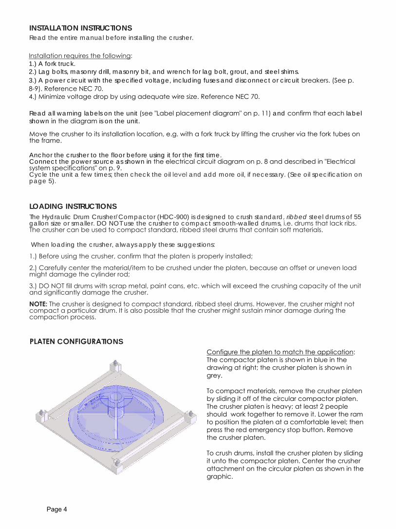
INSTALLATION INSTRUCTIONS Read the entire manual before installing the crusher.
Installation requires the following: 1.) A fork truck. 2.) Lag bolts, masonry drill, masonry bit, and wrench for lag bolt, grout, and steel shims. 3.) A power circuit with the specified voltage, including fuses and disconnect or circuit breakers. (See p. 8-9). Reference NEC 70. 4.) Minimize voltage drop by using adequate wire size. Reference NEC 70.
Read all warning labels on the unit (see "Label placement diagram" on p. 11) and confirm that each label shown in the diagram is on the unit.
Move the crusher to its installation location, e.g. with a fork truck by lifting the crusher via the fork tubes on the frame.
Anchor the crusher to the floor before using it for the first time. Connect the power source as shown in the electrical circuit diagram on p. 8 and described in "Electrical system specifications" on p. 9. Cycle the unit a few times; then check the oil level and add more oil, if necessary. (See oil specification on page 5).
LOADING INSTRUCTIONS The Hydraulic Drum Crusher/Compactor (HDC-900) is designed to crush standard, ribbed steel drums of 55 gallon size or smaller. DO NOT use the crusher to compact smooth-walled drums, i.e. drums that lack ribs. The crusher can be used to compact standard, ribbed steel drums that contain soft materials.
When loading the crusher, always apply these suggestions:
1.) Before using the crusher, confirm that the platen is properly installed;
2.) Carefully center the material/item to be crushed under the platen, because an offset or uneven load might damage the cylinder rod;
3.) DO NOT fill drums with scrap metal, paint cans, etc. which will exceed the crushing capacity of the unit and significantly damage the crusher.
NOTE: The crusher is designed to compact standard, ribbed steel drums. However, the crusher might not compact a particular drum. It is also possible that the crusher might sustain minor damage during the compaction process.
Page 4
PLATEN CONFIGURATIONS Configure the platen to match the application:The compactor platen is shown in blue in the drawing at right; the crusher platen is shown in grey.
To compact materials, remove the crusher platen by sliding it off of the circular compactor platen. The crusher platen is heavy; at least 2 people should work together to remove it. Lower the ram to position the platen at a comfortable level; then press the red emergency stop button. Remove the crusher platen.
To crush drums, install the crusher platen by sliding it unto the compactor platen. Center the crusher attachment on the circular platen as shown in the graphic.
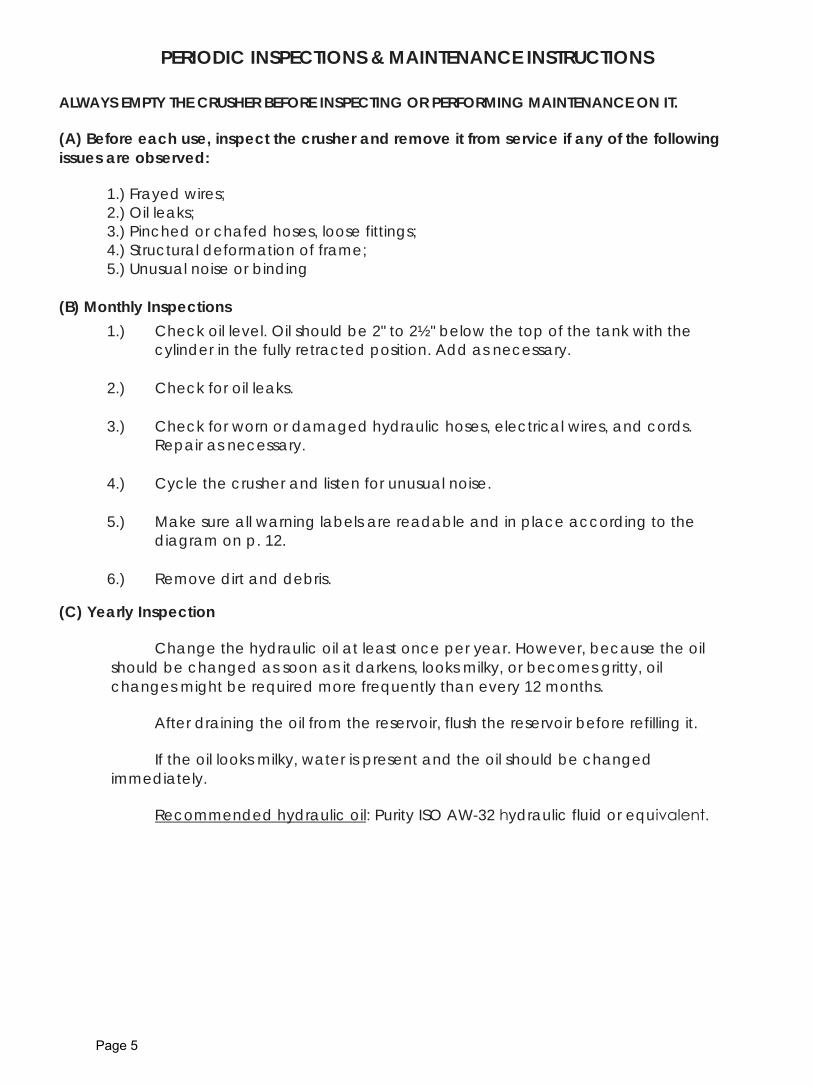
PERIODIC INSPECTIONS & MAINTENANCE INSTRUCTIONS
ALWAYS EMPTY THE CRUSHER BEFORE INSPECTING OR PERFORMING MAINTENANCE ON IT.
(A) Before each use, inspect the crusher and remove it from service if any of the following issues are observed:
1.) Frayed wires; 2.) Oil leaks; 3.) Pinched or chafed hoses, loose fittings; 4.) Structural deformation of frame; 5.) Unusual noise or binding
(B) Monthly Inspections 1.) Check oil level. Oil should be 2" to 2½" below the top of the tank with the
cylinder in the fully retracted position. Add as necessary.
2.) Check for oil leaks.
3.) Check for worn or damaged hydraulic hoses, electrical wires, and cords. Repair as necessary.
4.) Cycle the crusher and listen for unusual noise.
5.) Make sure all warning labels are readable and in place according to the diagram on p. 12.
6.) Remove dirt and debris.
(C) Yearly Inspection
Change the hydraulic oil at least once per year. However, because the oil should be changed as soon as it darkens, looks milky, or becomes gritty, oil changes might be required more frequently than every 12 months.
After draining the oil from the reservoir, flush the reservoir before refilling it.
If the oil looks milky, water is present and the oil should be changed immediately.
Recommended hydraulic oil: Purity ISO AW-32 hydraulic fluid or equivalent.
Page 5

1137030
1/2"-13 NYLO
N IN
SERT LOC
K NUT
110
11212H
HC
S #2 Z PLA
TED, 1/2 - 13 UN
C x 2 1/4 LG
.1
936114
HEX N
UT Z-PLATED
, Ø5/8 - 11 UN
C1
899-021-926
CYLIN
DER, 4 X 36 X 2.5
17
22-037-005W
ELDA
BLE PEAR LIN
K1
622-037-006
LOC
K, AD
JUSTING
ROD
1
522-037-004
AD
JUSTABLE YO
KE END
14
22-024-003G
UARD
, PLASTIC
CO
VER, PO
WER UN
IT1
322-023-004
RESERVO
IR, PLASTIC
12
22-514-008RO
UND
/SQUA
RE DRUM
CRUSH
ER OPTIO
N1
122-514-002
FRAM
E, SUBASSEM
BLY1
ITEM N
O.
PART N
UMBER
DESC
RIPTION
QTY.
8
4
3
1
2
5
6
79
10
11
FIG. 1: H
DC
-900 Exploded parts D
iagram &
Bill of M
aterials
Page 6A
fork tube

1510371
3/4 - 10 X 4 1/2 HH
CS #
2 PLAIN
1
1433630
3/4 lock wa
sher1
1336116
3/4-10 HEX NUT
112
370301/2"-13 N
YLON
INSERT LO
CK N
UT4
1133011
Ø1/2 USS FLA
T WA
SHER PLA
IN8
1011212
HH
CS #
2 Z PLATED
, 1/2 - 13 UNC
x 2 1/4 LG.
49
37021Ø
5/16-18 NYLO
N LO
CK N
UT, Z-PLATED
, #2
48
11055H
HC
S #2 Z PLA
TED, Ø
5/16 - 18 x 1 LG4
733620
Ø5/16 LO
CK W
ASH
ER Z PLATED
46
33006Ø
5/16 USS Flat W
asher Z Pla
ted4
522-514-024
ROUN
D/SQ
UARE D
RUM C
RUSHER SUB-A
SSEMBLY
14
22-024-003G
UARD
, PLASTIC
CO
VER, PO
WER UN
IT1
322-023-004
RESERVO
IR, PLASTIC
12
99-021-926C
YLIND
ER, 4 X 36 X 2.51
122-514-026
FRAM
E, SUBASSEM
BLY1
ITEM
NO
.PA
RT NUM
BERD
ESCRIPTIO
NQ
TY.
2
431
12
1115
5 1413
87
6
10
9
FIG. 2: H
DC
-905 Exploded P
arts Diagram
& B
ill of Materials
Page 6B
fork tube
Page 7A
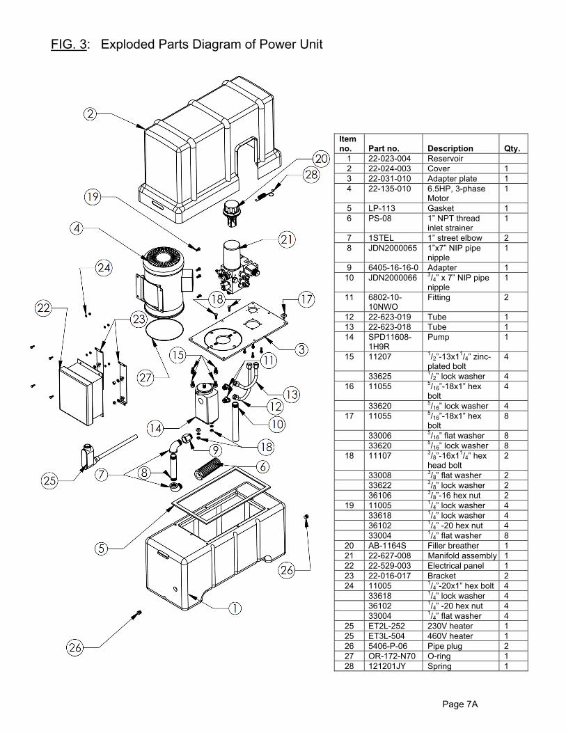
FIG. 3: Exploded Parts Diagram of Power Unit
Item no.
Part no. Description Qty.
1 22-023-004 Reservoir 2 22-024-003 Cover 1 3 22-031-010 Adapter plate 1 4 22-135-010 6.5HP, 3-phase
Motor 1
5 LP-113 Gasket 1 6 PS-08 1” NPT thread
inlet strainer 1
7 1STEL 1” street elbow 2 8 JDN2000065 1”x7” NIP pipe
nipple 1
9 6405-16-16-0 Adapter 110 JDN2000066 3/4” x 7” NIP pipe
nipple 1
11 6802-10-10NWO
Fitting 2
12 22-623-019 Tube 1 13 22-623-018 Tube 1 14 SPD11608-
1H9R Pump 1
15 11207 1/2”-13x11/4” zinc-plated bolt
4
33625 1/2” lock washer 4 16 11055 5/16”-18x1” hex
bolt 4
33620 5/16” lock washer 4 17 11055 5/16”-18x1” hex
bolt 8
33006 5/16” flat washer 8 33620 5/16” lock washer 8
18 11107 3/8”-16x11/4” hex head bolt
2
33008 3/8” flat washer 2 33622 3/8” lock washer 2 36106 3/8”-16 hex nut 2
19 11005 1/4” lock washer 4 33618 1/4” lock washer 4 36102 1/4” -20 hex nut 4 33004 1/4” flat washer 8
20 AB-1164S Filler breather 1 21 22-627-008 Manifold assembly 1 22 22-529-003 Electrical panel 1 23 22-016-017 Bracket 2 24 11005 1/4”-20x1” hex bolt 4 33618 1/4” lock washer 4 36102 1/4” -20 hex nut 4 33004 1/4” flat washer 4
25 ET2L-252 230V heater 1 25 ET3L-504 460V heater 1 26 5406-P-06 Pipe plug 2 27 OR-172-N70 O-ring 1 28 121201JY Spring 1

FIG. 4: Detailed Parts Breakdown of Manifold Assembly (Item No. 21 on p. 7A)
11
14
5
9
10
3
12
13
17
18
2
7
8
4
16
15
9
1
6
19
8
Item no. Part no. Description Quantity1 22-127-008 Manifold 1 2 22-031-007 Filter 1 3 99-153-028 Unloading valve 1 4 SHD-03G-3C60-A24D 4-way valve 1 5 99-153-037 Relief valve 1 6 99-022-004 Pressure switch 1 7 1710 PO check 1 8 99-153-035 Check valve 2 9 6408-H-04 Plug 2
10 1808-25 25psi check valve 1 11 6400-10-10 Fitting 1 12 99-153-015 2-way valve 1 13 99-034-008 24VAC coil 1 14 6400-10-08-0 Fitting 1 15 2-154 O-ring 4 16 23209 ¼ in. – 20 x 1 ½ in. SHCS bolt 4 17 6400-16-12 Fitting 1 18 10/10/6802 Fitting 1 19 99-022-005 Pressure switch 1
Page 7B

FIG. 5: Front view FIG. 6: Rear view
FIG. 7: Left side view FIG. 8: Right side view
Pressure switch #2 (port PS2)
Pressure switch (port PS1)
Gauge port (GA); install 3,000psi pressure gauge
Gauge port (UL GA); install 3,000psi pressure gauge
Set screw on knurled knob of pressure switch 1 [NOTE: The knurled knob of PS1 also has a set screw.]
Filter
Directional valve
Directional valve
Lower pressure switch (PS1)
Upper pressure
switch (PS2)
Filter
Adjusting Pressure Switch and Hydraulic Valve SettingsThe manifold assembly shown in Figures 1 – 4 below corresponds to item no. 21 on p. 7A & 7B.
Adjustment hex flats of relief valve
Sequence valve
Page 7C
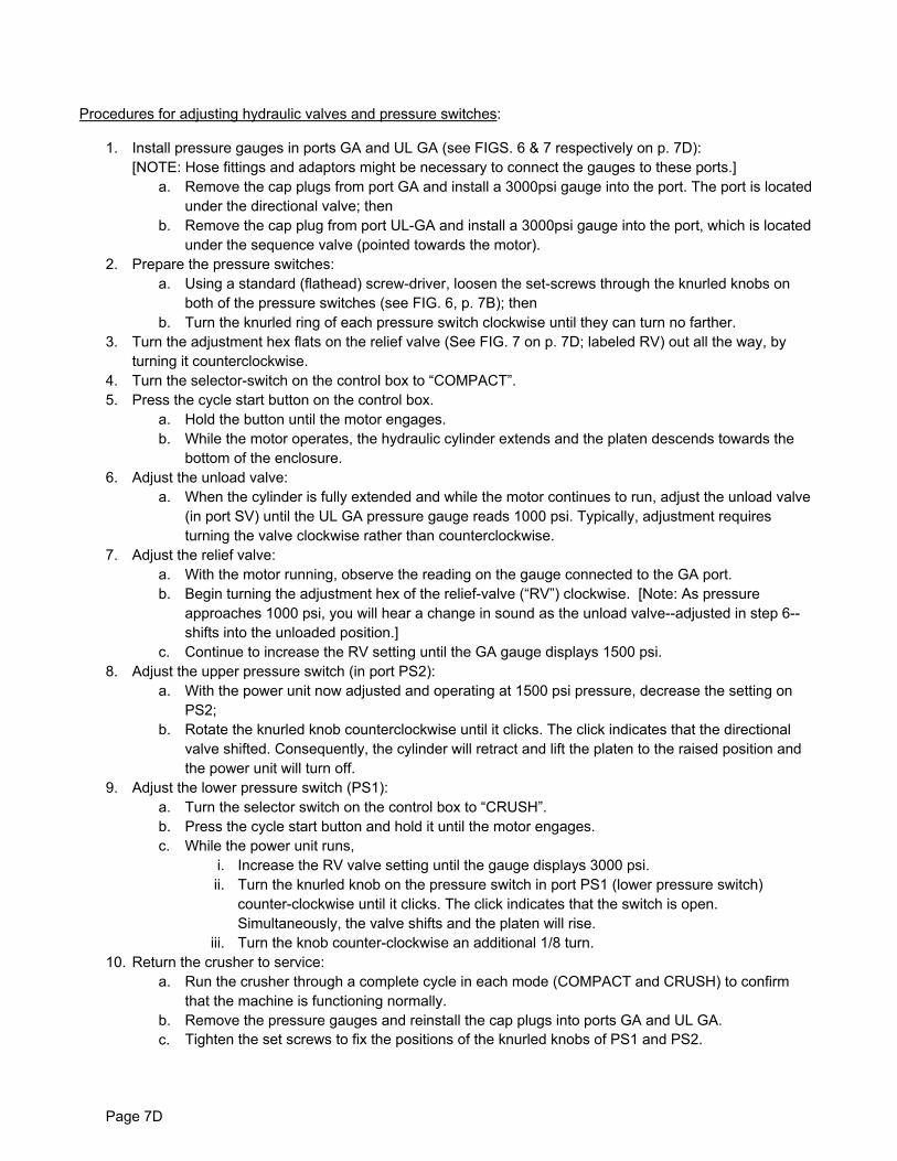
Procedures for adjusting hydraulic valves and pressure switches:
1. Install pressure gauges in ports GA and UL GA (see FIGS. 6 & 7 respectively on p. 7D):[NOTE: Hose fittings and adaptors might be necessary to connect the gauges to these ports.]
a. Remove the cap plugs from port GA and install a 3000psi gauge into the port. The port is locatedunder the directional valve; then
b. Remove the cap plug from port UL-GA and install a 3000psi gauge into the port, which is locatedunder the sequence valve (pointed towards the motor).
2. Prepare the pressure switches:a. Using a standard (flathead) screw-driver, loosen the set-screws through the knurled knobs on
both of the pressure switches (see FIG. 6, p. 7B); thenb. Turn the knurled ring of each pressure switch clockwise until they can turn no farther.
3. Turn the adjustment hex flats on the relief valve (See FIG. 7 on p. 7D; labeled RV) out all the way, byturning it counterclockwise.
4. Turn the selector-switch on the control box to “COMPACT”.5. Press the cycle start button on the control box.
a. Hold the button until the motor engages.b. While the motor operates, the hydraulic cylinder extends and the platen descends towards the
bottom of the enclosure.6. Adjust the unload valve:
a. When the cylinder is fully extended and while the motor continues to run, adjust the unload valve(in port SV) until the UL GA pressure gauge reads 1000 psi. Typically, adjustment requiresturning the valve clockwise rather than counterclockwise.
7. Adjust the relief valve:a. With the motor running, observe the reading on the gauge connected to the GA port.b. Begin turning the adjustment hex of the relief-valve (“RV”) clockwise. [Note: As pressure
approaches 1000 psi, you will hear a change in sound as the unload valve--adjusted in step 6--shifts into the unloaded position.]
c. Continue to increase the RV setting until the GA gauge displays 1500 psi.8. Adjust the upper pressure switch (in port PS2):
a. With the power unit now adjusted and operating at 1500 psi pressure, decrease the setting onPS2;
b. Rotate the knurled knob counterclockwise until it clicks. The click indicates that the directionalvalve shifted. Consequently, the cylinder will retract and lift the platen to the raised position andthe power unit will turn off.
9. Adjust the lower pressure switch (PS1):a. Turn the selector switch on the control box to “CRUSH”.b. Press the cycle start button and hold it until the motor engages.c. While the power unit runs,
i. Increase the RV valve setting until the gauge displays 3000 psi.ii. Turn the knurled knob on the pressure switch in port PS1 (lower pressure switch)
counter-clockwise until it clicks. The click indicates that the switch is open.Simultaneously, the valve shifts and the platen will rise.
iii. Turn the knob counter-clockwise an additional 1/8 turn.10. Return the crusher to service:
a. Run the crusher through a complete cycle in each mode (COMPACT and CRUSH) to confirmthat the machine is functioning normally.
b. Remove the pressure gauges and reinstall the cap plugs into ports GA and UL GA.c. Tighten the set screws to fix the positions of the knurled knobs of PS1 and PS2.
Page 7D

Electrical controls sequence of operation:
1) Press “Cycle start” button- 1M energizes; - Aux. contacts 13 and 14 close; - Terminal 8 energizes; - Power at CR2 9&1; - Power reaches 2LS normally open, held closed switch (NO, HC); - Power on 11 to CR1, 13 and 14; - CR1, 5 and 9 close (latch); - CR1, 2 and 10 open (timer); - Energize 2 SOL H (4-way, 3-position); - Ram and platen descend.
2) As the ram and platen descend:- 2 LS normally closed, held open switch (NC, HO) closes; - 2 LS NO, HC opens.
3) At the bottom of the cylinder (ram) stroke:- PS1 (if in “CRUSH” mode) or PS2 (if in “COMPACT” mode) make; - Energizes CR2, 13 and 14; - CR2, 9 and 1 open; - 2 SOL H de-energize; - CR1, 13 and 14 de-energize; - CR1, 2 and 10 close and the timer starts.
4) Timer cycle:- CR1, 3 and 11 close; - Power reaches decompression valve 3 SOL H; - 1-2 second delay; - CR3, 2 and 10 open; - 3 SOL H de-energizes and closes; - CR3, 5 and 9 close; - Power to 1 SOL H causing the ram and platen to ascend.
5) As the cylinder retracts, causing the ram and platen to return to the ready position:- 2 LS normally closed switch opens; and - 1M de-energizes.
Page 7E

Page 8
FIG. 9: E
lectrical system diagram
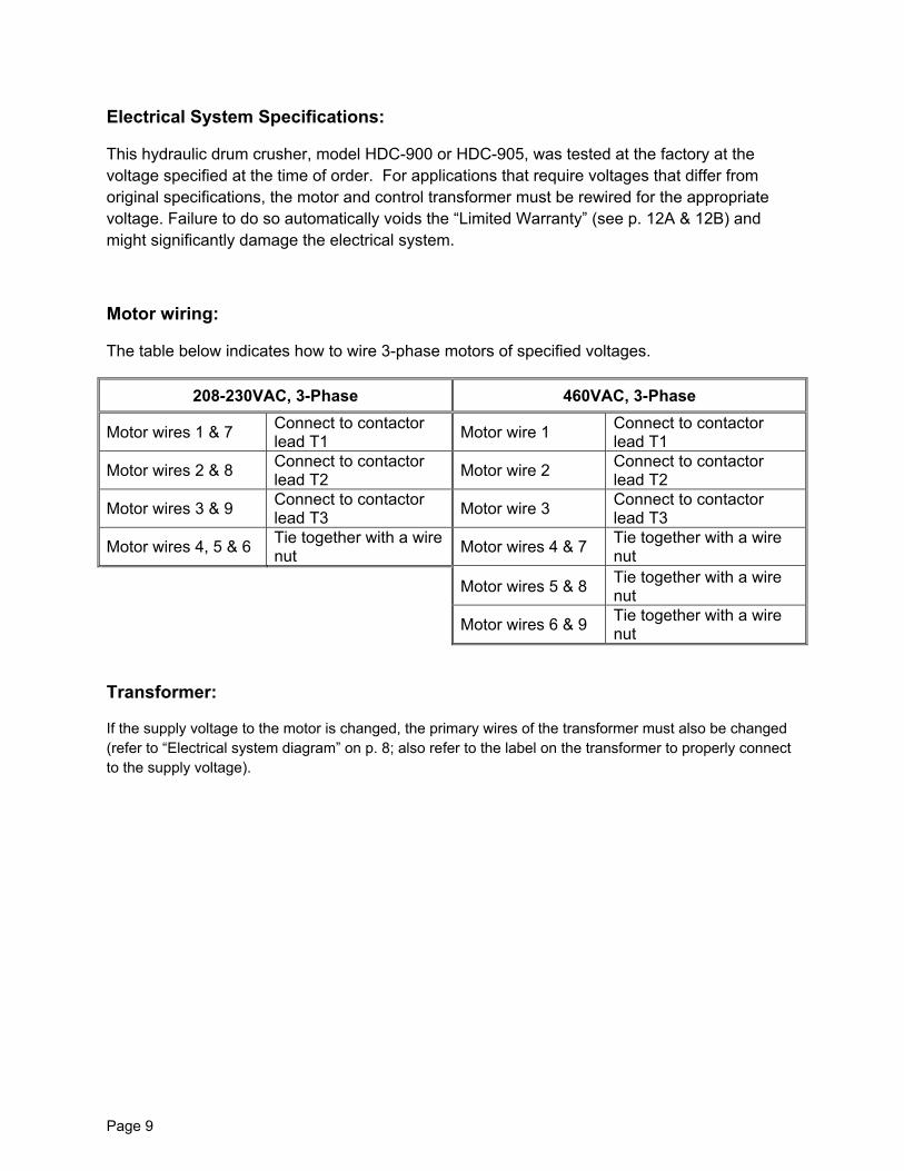
Electrical System Specifications:
This hydraulic drum crusher, model HDC-900 or HDC-905, was tested at the factory at the voltage specified at the time of order. For applications that require voltages that differ from original specifications, the motor and control transformer must be rewired for the appropriate voltage. Failure to do so automatically voids the “Limited Warranty” (see p. 12A & 12B) and might significantly damage the electrical system.
Motor wiring:
The table below indicates how to wire 3-phase motors of specified voltages.
208-230VAC, 3-Phase 460VAC, 3-Phase
Motor wires 1 & 7 Connect to contactor lead T1 Motor wire 1 Connect to contactor
lead T1
Motor wires 2 & 8 Connect to contactor lead T2 Motor wire 2 Connect to contactor
lead T2
Motor wires 3 & 9 Connect to contactor lead T3 Motor wire 3 Connect to contactor
lead T3
Motor wires 4, 5 & 6 Tie together with a wire nut Motor wires 4 & 7 Tie together with a wire
nut
Motor wires 5 & 8 Tie together with a wire nut
Motor wires 6 & 9 Tie together with a wire nut
Transformer:
If the supply voltage to the motor is changed, the primary wires of the transformer must also be changed (refer to “Electrical system diagram” on p. 8; also refer to the label on the transformer to properly connect to the supply voltage).
Page 9
M
14
243
1
1211
78
13
159
6
10
5
16
Page 10
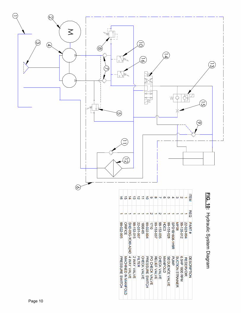
FIG. 10: H
ydraulic System
Diagram
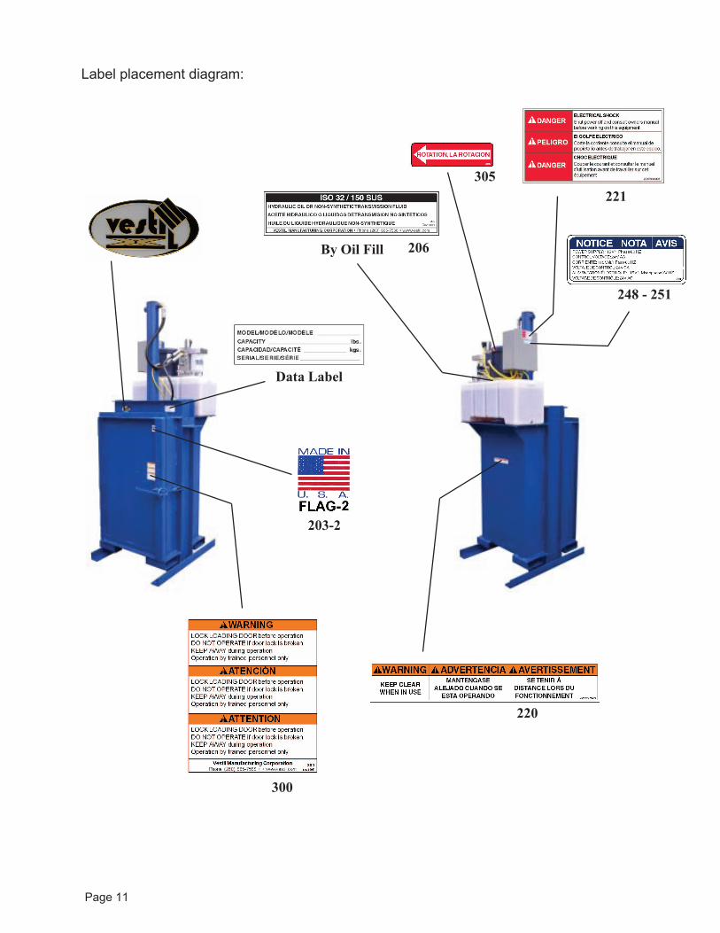
Data Label
221305
206
220
248 - 251
By Oil Fill
300
203-2
Page 11
Label placement diagram:

Rev. 01/2011
LIMITED WARRANTY
Vestil Manufacturing Corporation (“Vestil”) warrants this HDC-900 (excluding “Washdown” model HDC-905-WD, which is covered by a separate warranty) to be free of defects in material and workmanship during the warranty period. Our warranty obligation is to provide a replacement for a defective original part if the part is covered by the warranty, after we receive a proper request from the warrantee (you) for warranty service.
Who may request service? Only a warrantee may request service. You are a warrantee if you purchased the product from Vestil or from an authorized distributor AND Vestil has been fully paid.
What is an “original part”? An original part is a part used to make the product as shipped to the warrantee.
What is a “proper request”? A request for warranty service is proper if Vestil receives: 1) a photocopy of the Customer Invoice that displays the shipping date; AND 2) a written request for warranty service including your name and phone number. Send requests by any of the following methods:
Mail Fax Email Vestil Manufacturing Corporation (260) 665-1339 [email protected] 2999 North Wayne Street, PO Box 507 Phone Angola, IN 46703 (260) 665-7586
In the written request, list the parts believed to be defective and include the address where replacements should be delivered.
What is covered under the warranty? After Vestil receives your request for warranty service, an authorized representative will contact you to determine whether your claim is covered by the warranty. Before providing warranty service, Vestil may require you to send the entire product, or just the defective part or parts, to its facility in Angola, IN. The warranty covers defects in the following original dynamic components: motors, hydraulic pumps, electronic controllers, switches and cylinders. It also covers defects in original parts that wear under normal usage conditions (“wearing parts”): bearings, hoses, wheels, seals, brushes, batteries, and the battery charger.
How long is the warranty period? The warranty period for original components is 1 year. The warranty period begins on the date when Vestil ships the product to the warrantee. If the product was purchased from an authorized distributor, the period begins when the distributor ships the product. Vestil may extend the warranty period for products shipped from authorized distributors by up to 30 days to account for shipping time.
If a defective part is covered by the warranty, what will Vestil do to correct the problem? Vestil will provide an appropriate replacement for any covered part. An authorized representative of Vestil will contact you to discuss your claim.
What is not covered by the warranty? 1. Labor;2. Freight;3. Occurrence of any of the following, which automatically voids the warranty:
Product misuse; Negligent operation or repair; Corrosion or use in corrosive conditions; Inadequate or improper maintenance; Damage sustained during shipping; Accidents involving the product; Unauthorized modifications: DO NOT modify the product IN ANY WAY without first receiving
written authorization from Vestil. Modification(s) might make the product unsafe to use or mightcause excessive and/or abnormal wear.
Do any other warranties apply to the product? Vestil Manufacturing Corp. makes no other express warranties. All implied warranties are disclaimed to the extent allowed by law. Any implied warranty not disclaimed is limited in scope to the terms of this Limited Warranty.
Page 12A
LIMITED WARRANTY
Vestil Manufacturing Corporation (“Vestil”) warrants this HDC-905-WD drum crusher to be free of defects in material and workmanship during the warranty period. Our warranty obligation is to provide a replacement for a defective original part if the part is covered by the warranty, after we receive a proper request from the warrantee (you) for warranty service.
Who may request service? Only a warrantee may request service. You are a warrantee if you purchased the product from Vestil or from an authorized distributor AND Vestil has been fully paid.
What is an “original part”? An original part is a part used to make the product as shipped to the warrantee.
What is a “proper request”? A request for warranty service is proper if Vestil receives: 1) a photocopy of the Customer Invoice that displays the shipping date; AND 2) a written request for warranty service including your name and phone number. Send requests by any of the following methods:
Mail Fax Email Vestil Manufacturing Corporation (260) 665-1339 [email protected] 2999 North Wayne Street, PO Box 507 Phone Angola, IN 46703 (260) 665-7586
In the written request, list the parts believed to be defective and include the address where replacements should be delivered.
What is covered under the warranty? After Vestil receives your request for warranty service, an authorized representative will contact you to determine whether your claim is covered by the warranty. Before providing warranty service, Vestil may require you to send the entire product, or just the defective part or parts, to its facility in Angola, IN. The warranty covers defects in the following original dynamic components: motors, hydraulic pumps, electronic controllers, switches and cylinders. It also covers defects in original parts that wear under normal usage conditions (“wearing parts”): bearings, hoses, wheels, seals, brushes, batteries, and the battery charger.
How long is the warranty period? The warranty period for original components is 30 days. The warranty period begins on the date when Vestil ships the product to the warrantee. If the product was purchased from an authorized distributor, the period begins when the distributor ships the product. Vestil may extend the warranty period for products shipped from authorized distributors by up to 30 days to account for shipping time.
If a defective part is covered by the warranty, what will Vestil do to correct the problem? Vestil will provide an appropriate replacement for any covered part. An authorized representative of Vestil will contact you to discuss your claim.
What is not covered by the warranty? 1. Labor;2. Freight;3. Occurrence of any of the following, which automatically voids the warranty:
Product misuse; Negligent operation or repair; Corrosion or use in corrosive conditions; Inadequate or improper maintenance; Damage sustained during shipping; Accidents involving the product; Unauthorized modifications: DO NOT modify the product IN ANY WAY without first receiving
written authorization from Vestil. Modification(s) might make the product unsafe to use or mightcause excessive and/or abnormal wear.
Do any other warranties apply to the product? Vestil Manufacturing Corp. makes no other express warranties. All implied warranties are disclaimed to the extent allowed by law. Any implied warranty not disclaimed is limited in scope to the terms of this Limited Warranty.
Page 12B