safety suite device configurator user guide - honeywell · safety suite device configurator...
TRANSCRIPT

Safety Suite Device Configurator
USER GUIDE
© 2020 Honeywell Inc Rev. J, Jan 2020
Contents
1 Introduction ............................................................................................................................ 6
2 Requirements ......................................................................................................................... 6
2.1 Hardware ...................................................................................................................... 6
2.2 Software ........................................................................................................................ 6
3 Installation .............................................................................................................................. 6
4 First Time Start-Up ............................................................................................................... 10
4.1 Username ................................................................................................................... 12
4.2 Password .................................................................................................................... 12
4.3 Security Questions ...................................................................................................... 12
4.4 Software Registration .................................................................................................. 14
5 Logging In ............................................................................................................................ 16
5.1 Password Recovery for Non-Administrators ................................................................ 18
5.2 Password Recovery for Administrators ........................................................................ 18
5.3 Password expiry. ......................................................................................................... 19
5.4 Login Process ............................................................................................................. 22
6 Supported Instruments ......................................................................................................... 23
6.1 IntelliDoX & MicroDock II ............................................................................................. 23
6.2 IntelliDoX ..................................................................................................................... 23
6.3 MicroDock II ................................................................................................................ 23
6.4 BW IR Dongle ............................................................................................................. 23
6.5 AutoRAE 2 & Travel Charger ...................................................................................... 23
6.6 Direct USB .................................................................................................................. 23
6.7 Migration from Existing software ................................................................................. 24
6.7.1 Fleet Manager ............................................................................................... 24
6.7.2 ProRAE Studio II ........................................................................................... 24
6.7.3 IQ Management Software Suite ..................................................................... 24
7 Connecting an Instrument to Your Computer ........................................................................ 24
7.1 Connection via IntelliDoX ............................................................................................ 24
7.2 Connection via AutoRAE 2 .......................................................................................... 25
7.3 Connection via MicroDock II ........................................................................................ 25
7.4 Download IntelliDox / GA Micro5 data ......................................................................... 25
7.5 View/Save IntelliDox Configuration File ....................................................................... 26
7.6 Microdock-view/save config from file ........................................................................... 29
7.7 Load Default MicroDock Configuration ........................................................................ 32
7.8 Load Default IntelliDox Configuration .......................................................................... 33

3
8 Security ................................................................................................................................ 35
8.1 Data Security .............................................................................................................. 36
8.2 Wireless Security Warning .......................................................................................... 36
9 Starting Safety Suite Device Configurator from the Desktop ................................................. 36
10 Title Bar/Quick-Access Toolbar ............................................................................................ 37
10.1 Registrations ............................................................................................................. 37
10.2 Devices ..................................................................................................................... 37
10.3 Notifications .............................................................................................................. 38
10.4 Role Information ........................................................................................................ 38
10.4.1 Role Name ................................................................................................ 39
10.4.1.1 Role Names and Access Levels ..................................................... 39
10.4.2 Edit Profile ................................................................................................. 39
10.4.2.1 Update Profile Picture .................................................................... 40
10.4.2.2 Personal Information ..................................................................... 41
10.4.2.3 Change Password ......................................................................... 41
10.4.2.4 Update Security Questions ............................................................ 41
10.4.3 Sign Out .................................................................................................... 41
10.4.4 Settings ..................................................................................................... 42
10.4.4.1 System Settings ............................................................................ 42
10.4.4.2 Manage and Assign Locations ....................................................... 45
10.4.4.3 Email Settings ............................................................................... 47
10.4.4.4 Network Settings ........................................................................... 48
10.4.5 User Role List ............................................................................................ 49
10.5 Help .......................................................................................................................... 49
11 Views ................................................................................................................................... 50
11.1 Devices ..................................................................................................................... 50
11.1.1 Device Hierarchy ....................................................................................... 51
11.1.2 Manage Columns ...................................................................................... 52
11.1.3 Refresh ...................................................................................................... 52
11.1.4 List View .................................................................................................... 52
12 Assign Device to Worker .................................................................................................... 53
13 Filter by .............................................................................................................................. 54
13.1 Connection ................................................................................................................ 55
13.2 Devices ..................................................................................................................... 56
13.3 Assigned Worker ....................................................................................................... 57
13.4 Last Download .......................................................................................................... 57
13.5 Last Bump ................................................................................................................. 58
4
13.6 Last Calibration ......................................................................................................... 58
13.7 Device Status ............................................................................................................ 59
14 Device List View ................................................................................................................. 59
14.1 Download data .......................................................................................................... 61
14.2 Set Parameters ......................................................................................................... 61
14.3 Event Log .................................................................................................................. 63
14.4 Bump/Cal Results ..................................................................................................... 64
14.5 Datalogs .................................................................................................................... 64
15 Actions ............................................................................................................................... 65
15.1 Device Details ........................................................................................................... 65
15.1.1 Instruments ............................................................................................... 66
15.1.2 Docking Stations ....................................................................................... 67
15.1.2.1 Menu Passcode ............................................................................. 69
15.1.2.2 Edit Gas Cylinder Configuration .................................................... 69
15.2 Device History ........................................................................................................... 70
15.2.1 Filters ........................................................................................................ 72
15.3 Sensors ..................................................................................................................... 76
15.4 Settings ..................................................................................................................... 78
15.5 Archive Device .......................................................................................................... 79
15.6 Network Passcode .................................................................................................... 79
16 Custom fields in Device Configurator .................................................................................. 80
17 Scheduled data import ........................................................................................................ 85
18 Bulk Data log export ........................................................................................................... 88
19 User List ............................................................................................................................. 91
19.1 Sort by....................................................................................................................... 92
19.2 Manage Columns ...................................................................................................... 92
19.3 Actions ...................................................................................................................... 93
19.4 Add A User ................................................................................................................ 93
19.5 Profile Picture ............................................................................................................ 94
19.6 Filter By ..................................................................................................................... 95
19.6.1 Status ........................................................................................................ 95
19.6.2 Name......................................................................................................... 97
19.6.3 Device Assigned ........................................................................................ 98
19.6.4 User Role .................................................................................................. 98
19.6.5 Username .................................................................................................. 99
19.7 Download/Upload Bulk User Import File .................................................................. 100
20 Generate Report ............................................................................................................... 104

5
20.1 Multidevice reports-Eventlog(Multidevice event report) ........................................... 106
20.2 Custom Report ........................................................................................................ 108
20.2.1 Create Custom Report .............................................................................. 108
20.2.2 Template type ........................................................................................... 109
20.2.3 Scheduler ................................................................................................. 111
21 BW Solo Connectivity over Bluetooth to SSDC ................................................................. 116
21.1 Pre-requisites .......................................................................................................... 116
21.2 Pairing BW Solo over Bluetooth in Windows ........................................................... 117
21.3 Working with BW Solo in Safety Suite ..................................................................... 120
22 Uninstall Safety Suite Device Configurator ....................................................................... 122
22.1 Device Configurator Data Backup ........................................................................... 123
22.2 Delete Instrument Data (Optional) ........................................................................... 126
22.2.1 Uninstall Microsoft SQL Server 2012 ........................................................ 126
22.2.2 Device configurator Data Restore ............................................................. 131
23 Migrating ProRAE Studio Database to Safety Suite Device Configurator ......................... 139
24 Migrating Fleet Manager Database to Safety Suite Device Configurator ......................... 142
25 Migrating IQ Manager Database to Safety Suite Device Configurator .............................. 145
25.1 Backup of Source Files ........................................................................................... 147
26 Device Configurator FAQs .................................................................................................. 148
26.1 General Questions .................................................................................................. 148
26.2 Installation ............................................................................................................... 150
26.3 Login ....................................................................................................................... 154
26.4 Device Inventory ..................................................................................................... 156
26.5 Device Data Download ............................................................................................ 158
26.6 Device Configuration ............................................................................................... 159
26.7 Device History ......................................................................................................... 160
26.8 User Management ................................................................................................... 161
26.9 Data Migration ......................................................................................................... 162
26.10 Firmware ............................................................................................................... 164
26.11 Passcode .............................................................................................................. 167
26.12 Language Support ................................................................................................. 167
26.13 Device Registration ............................................................................................... 168
26.14 Event Report ......................................................................................................... 168

6
1 Introduction
Safety suite Device Configurator software allows data logs and configuration
settings from supported Honeywell instruments to be downloaded to a
computer, and configurations to be uploaded from a computer to the
instruments. Templates can be created, saved, and edited, as well as
user/instrument references.
Safety suite Device Configurator communicates with supported instruments via
supporting docking stations and USD direct connection when configuring them
or retrieving their data logs or event logs. Refer to your product’s manual for
details on connecting with a computer, as well as all safety requirements.
This version of the software allows you to:
• Download data logs
• Download configuration settings
• Change and upload new configurations settings
• Update firmware
• Download reports
• Create, edit, store, and upload templates
• Upload historical data from Fleet Manager
2 Requirements
2.1 Hardware
CPU :1GHz or better
Monitor :Color Monitor with resolution of at least 1024 x 768,16-bit color
Memory (RAM) :2GB
Disk Space :At least 4GB of free space
2.2 Software
Operating System: Windows 7 (32-bit and 64-bit), and Windows 10 (64-bit).
3 Installation
Download Safety Suite Device Configurator from
https://pages8.honeywell.com/safetysuite-device-configurator.html#download
1. Double-click on the filename, and start the installation process. During
installation of Device Configurator, the user can select the appropriate locale
7
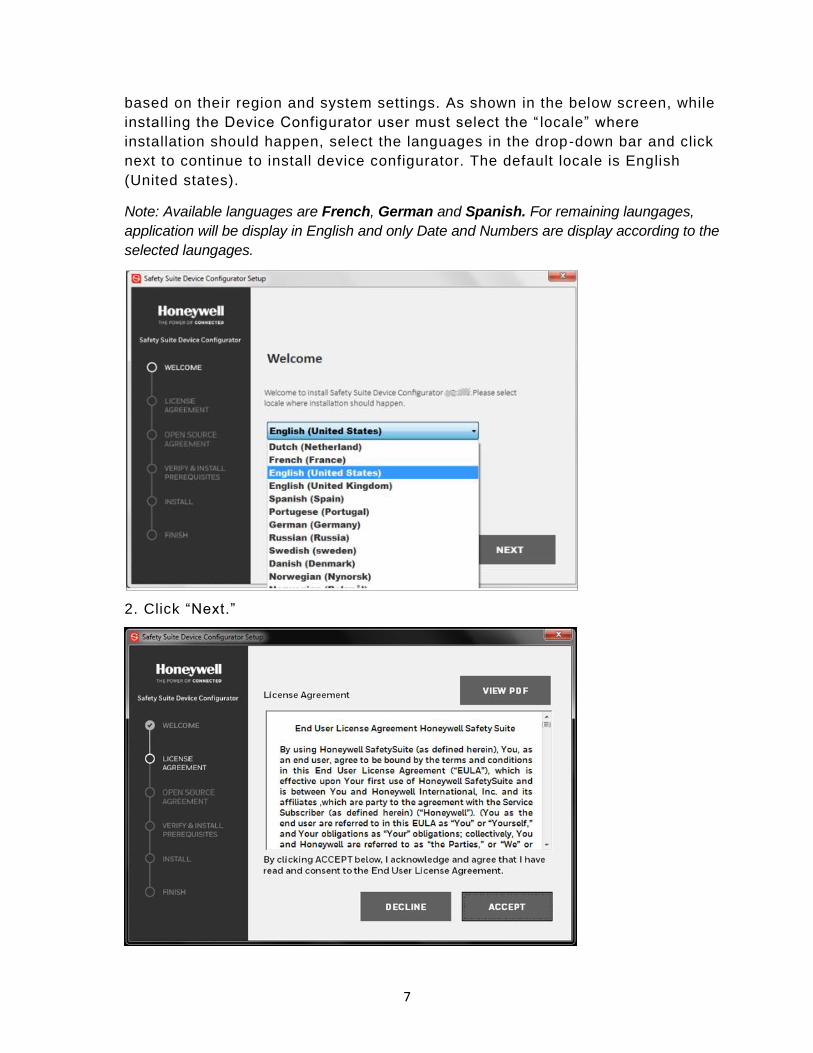
based on their region and system settings. As shown in the below screen, while
installing the Device Configurator user must select the “ locale” where
installation should happen, select the languages in the drop-down bar and click
next to continue to install device configurator. The default locale is English
(United states).
Note: Available languages are French, German and Spanish. For remaining laungages,
application will be display in English and only Date and Numbers are display according to the
selected laungages.
2. Click “Next.”
8
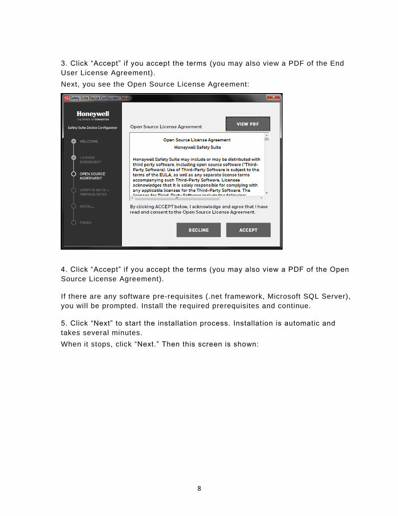
3. Click “Accept” if you accept the terms (you may also view a PDF of the End
User License Agreement).
Next, you see the Open Source License Agreement:
4. Click “Accept” if you accept the terms (you may also view a PDF of the Open
Source License Agreement).
If there are any software pre-requisites (.net framework, Microsoft SQL Server),
you will be prompted. Install the required prerequisites and continue.
5. Click “Next” to start the installation process. Installation is automatic and
takes several minutes.
When it stops, click “Next.” Then this screen is shown:

9
6. Click “Next” to begin the second part of installation.
7. Next, it shows this window to let you know configuration is going on.
When the installation is complete, this window appears:
10
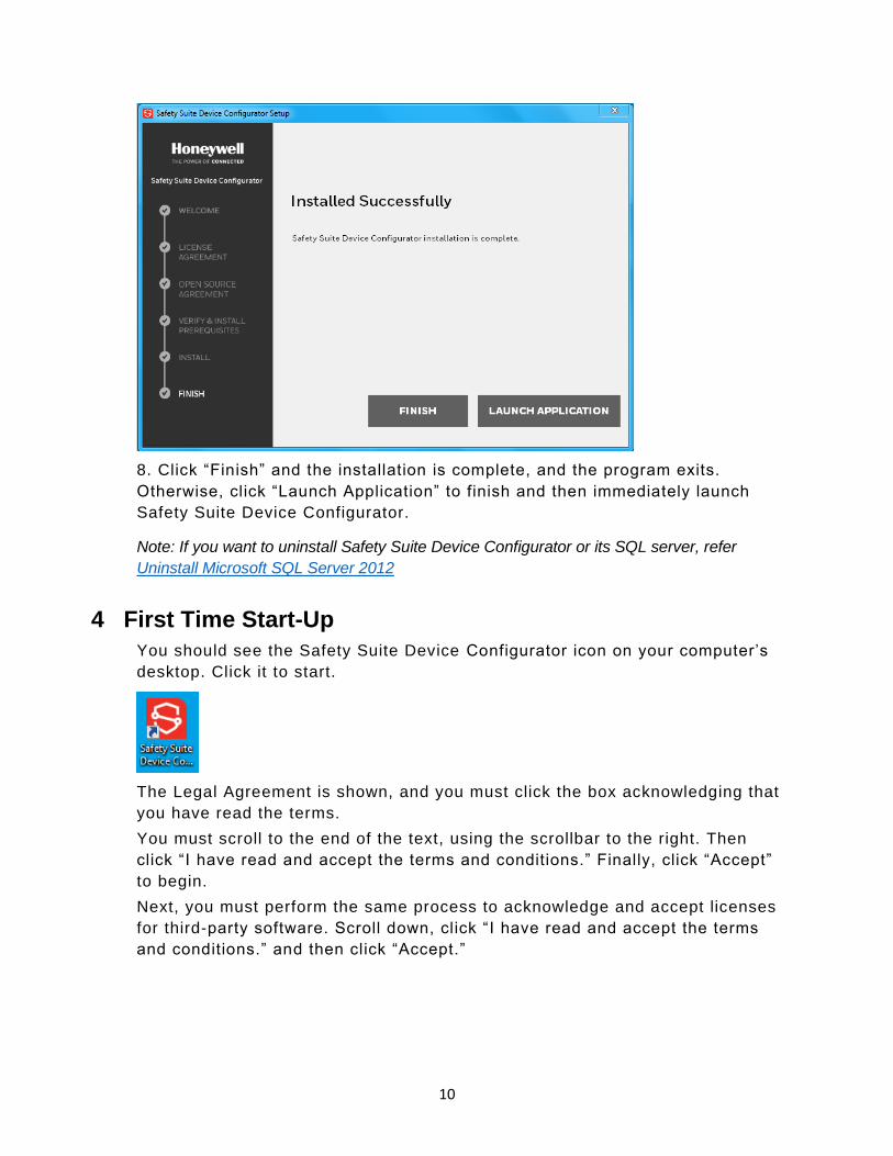
8. Click “Finish” and the installation is complete, and the program exits.
Otherwise, click “Launch Application” to finish and then immediately launch
Safety Suite Device Configurator.
Note: If you want to uninstall Safety Suite Device Configurator or its SQL server, refer
Uninstall Microsoft SQL Server 2012
4 First Time Start-Up
You should see the Safety Suite Device Configurator icon on your computer’s
desktop. Click it to start.
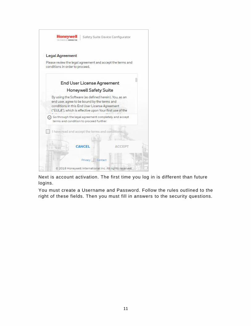
The Legal Agreement is shown, and you must click the box acknowledging that
you have read the terms.
You must scroll to the end of the text, using the scrollbar to the right. Then
click “I have read and accept the terms and conditions.” Finally, click “Accept”
to begin.
Next, you must perform the same process to acknowledge and accept licenses
for third-party software. Scroll down, click “I have read and accept the terms
and conditions.” and then click “Accept.”
11
Next is account activation. The first time you log in is different than future
logins.
You must create a Username and Password. Follow the rules outlined to the
right of these fields. Then you must fil l in answers to the security questions.

12
Be sure to scroll down and complete the process.
4.1 Username
You must create a username, which will be used each time your login to Safety
Suite Device Configurator.
4.2 Password
You should change the password every 90 days. You must supply the current
password and then type the new password. The password must follow these
rules:
• The password must have a minimum of 8 characters.
• The password must include at least one character from all the following
types:
✓ UPPERCASE
✓ lowercase
✓ Number: 0 1 2 3 4 5 6 7 8 9
✓ Special character, including: ! @ # $ % ^ * ( )
4.3 Security Questions

13
In case you ever forget your password and want to reset it, you will have to
answer security questions. Here is where you put the answers that must be
matched if you want to regain access after forgetting your password.
1. Select a security question from each pull-down list.
2. Type in an answer for each of the questions.
3. Click “Update”.
In case you should ever forget your password, you will have to answer security
questions for access. Here is where you put the answers to the security
questions.
1. Select a security question from each pull-down list.
2. Type in an answer for each of the questions.
After you establish a username and password, type the letters showing in the
box, following the same format of capital and lower-case letters. You can
refresh this by clicking the circle/arrow image to its right.
Scroll down and fill in the rest of the information, including typing the case-
sensitive text in the Captcha.

14
If all information is accepted and you submit the correct letters, then the
“Continue” button is highlighted.
Click the “Continue” button .
4.4 Software Registration
Register your software before you begin using Safety Suite Device
Configurator.

15
Fill in the information, and then scroll down to complete the process. Make sure
you fill in all information in fields marked with an asterisk (*).

16
When you have provided sufficient information, the “Register” button is b lue.
You can now click it to register.
Once registration is complete, this message is shown:
Safety Suite Device Configurator is ready to use.
5 Logging In
After your initial setup and registration procedure, you may simply login To
Safety Suite Device Configurator using your Username and Password. If you
wish to remain connected until you log out, click the “Keep me signed in” box.
Otherwise, Safety Suite Device Configurator locks any signed-in user out of the
system after 15 minutes of inactivity.

17

18
5.1 Password Recovery for Non-Administrators
If you forgot your password, click the link and follow instructions for resetting
the password.
5.2 Password Recovery for Administrators
If you have Administrator access and forgot your password, follow these steps:
1. Click the “Windows” icon on the lower left side of your screen.
2. Click “All apps.”

19
3. Scroll down until you see “Honeywell.” Click the downward arrow to see “Unlock
Administrator Account.”
4. When the “Windows Security” window appears, type in your Administrator password
for the PC.
5. Click “OK.” An activation code is shown.
6. Use this activation code to login to Safety Suite Device Configurator.
5.3 Password expiry.
The expiry date for each password is 90 days from the day it is set or changed,
When your password approaches the expiry date (85 – 90 th day), a warning pop
up will appear on the screen to remind you to change the password.

20
Click on “CHANGE PASSWORD” and change your password.
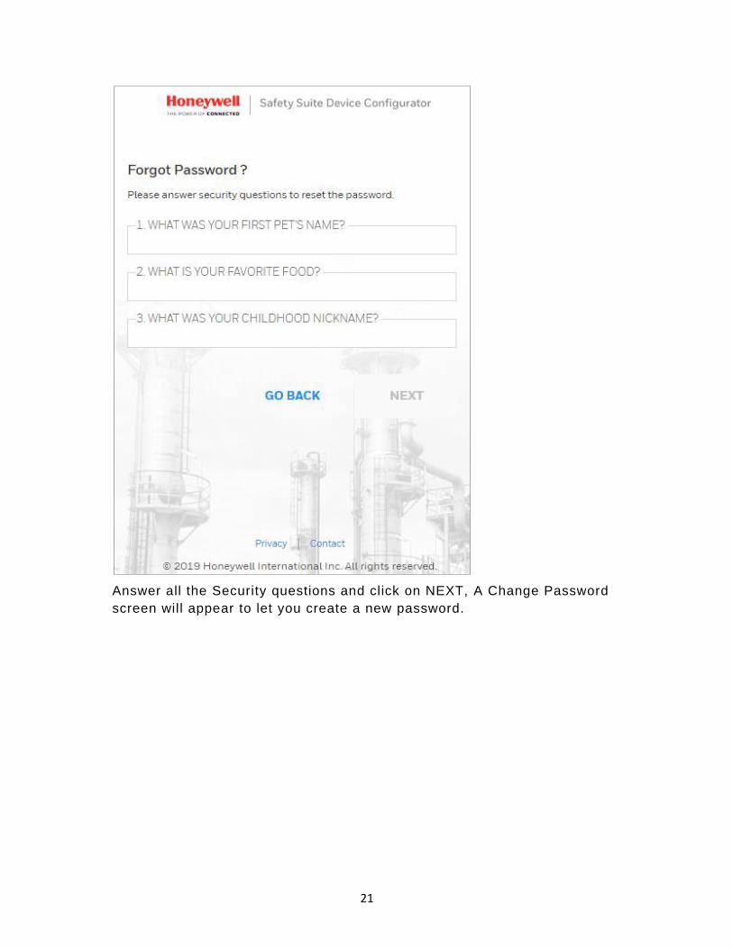
If your password expired, then click on “CHANGE PASSWORD” and answer the
security questions.
21
Answer all the Security questions and click on NEXT, A Change Password
screen will appear to let you create a new password.

22
5.4 Login Process
During login, Safety Suite Device Configurator checks whether you have
registered your software. If it has not been registered, then this window
appears to prompt you. You can fill in the fields and click “Register” to send
your registration.
The main screen is shown in its default state, with Devices selected in List View.
Note: You may not see the list until you have used the Settings page.

23
For details on navigating and using Safety Suite Device Configurator features,
click the “Help” button at the upper right corner of the screen .
6 Supported Instruments
6.1 IntelliDoX & MicroDock II
• BW Clip & BW Clip Real Time
• BW MicroClip XL & BW MicroClip X3
6.2 IntelliDoX
• BW Clip4
• BW Solo
• BW Ultra
6.3 MicroDock II
• BW MaxXT II
• BW Quattro
• GasAlertMicro 5
6.4 BW IR Dongle
• BW MaxXT II
• BW MicroClip XL & BW MicroClip X3
• BW Quattro
• BW Ultra
6.5 AutoRAE 2 & Travel Charger
• MicroRAE
• MiniRAE 3000 & MiniRAE Lite
• MultiRAE, MultiRAE Lite & MultiRAE Pro
• ppbRAE 3000
• QRAE 3
• ToxiRAE Pro, ToxiRAE Pro CO2, ToxiRAE Pro LEL & ToxiRAE Pro PID
• UltraRAE 3000
6.6 Direct USB
24
• AreaRAE Plus & AreaRAE Pro
6.7 Migration from Existing software
6.7.1 Fleet Manager
• BW Clip & BW Clip Real Time
• BW Clip4
• BW MaxXT II
• BW MicroClip XL & BW MicroClip X3
• BW Quattro
• BW Ultra
• GasAlert Extreme
• GasAlertMicro 5
6.7.2 ProRAE Studio II
• AreaRAE Plus & AreaRAE Pro
• MicroRAE
• MiniRAE 3000 & MiniRAE Lite
• MultiRAE, MultiRAE Lite & MultiRAE Pro
• ppbRAE 3000
• QRAE 3
• ToxiRAE Pro, ToxiRAE Pro CO2, ToxiRAE Pro LEL & ToxiRAE Pro PID
• UltraRAE 3000
6.7.3 IQ Management Software Suite
• ToxiPro
7 Connecting an Instrument to Your Computer
Your instrument must be connected via wire (USB or Serial) to the computer,
turned on, and in communication mode to transmit and receive data via Safety
Suite Device Configurator.
Different instruments require different connection methods to connect to a PC.
Follow the instructions in the user’s guide that accompanies the instrument,
ensuring that you use the correct cable and communication method. In addition,
you should make sure the instrumen t’s battery is charged.
7.1 Connection via IntelliDoX

25
Follow this procedure for reading data from an IntelliDoX:
1. Connect one end of an Ethernet cable (refer to the IntelliDoX User’s
Guide for connection and configuration information) to the
IntelliDoX and the other end to a PC running Safety Suite Device
Configurator software or the local network in case the dock needs
to communicate with the software over the network .
2. Make sure the IntelliDoX has power and is turned on.
3. Start Safety Suite Device Configurator software on the PC.
4. Add IntelliDoX IP to Safety Suite Device Configurator using the
settings option. For more information, please refer the “Product
Services” section.
5. Network Passcode is applicable/available on IntelliDoX device
having firmware 9.0 and above only. So, before you perform the
next step please set a passcode. For more information please refer
“Network Passcode” section.
7.2 Connection via AutoRAE 2
Follow this procedure for reading data from an AutoRAE 2 Controller:
1 Connect a USB cable (or use an Ethernet cable or Wi-Fi; refer to
the AutoRAE 2 User’s Guide for connection and configuration
information) to the AutoRAE 2 Controller and to a PC running
Safety Suite Device Configurator software.
2 Make sure the AutoRAE 2 Controller has power and is turned on.
3 Start Safety Suite Device Configurator software on the PC.
4 Add AutoRAE IP (if connected through network) to Safety Suite
Device Configurator using the settings option. For more
information, please refer the “Product Services” section.
7.3 Connection via MicroDock II
Follow this procedure for reading data from a MicroDock II :
1 Connect a USB cable to the MicroDock II and to a PC running
Safety Suite Device Configurator software.
2 Make sure the MicroDock II has power and is turned on.
3 Start Safety Suite Device Configurator on the PC.
7.4 Download IntelliDox / GA Micro5 data
Click on Download IntelliDox / GA Micro5 data in Devices options as shown
in the below screen.

26
Click on SELECT FOLDER and select the Data file from external devices (Pen
drive/Data card) to download the Data into Safety Suite Device configurator.
7.5 View/Save IntelliDox Configuration File
This is the configuration settings for IntelliDox devices. You can easily view,
edit and save the configuration file. To view the configuration file, click on
View/Save IntelliDox Configuration File from the top right-hand side menu
dropdown as shown below.
After clicking on View/Save IntelliDox Configuration File, below screen will
appear to select the intelliDox configuration file (Download from IntelliDox).
27
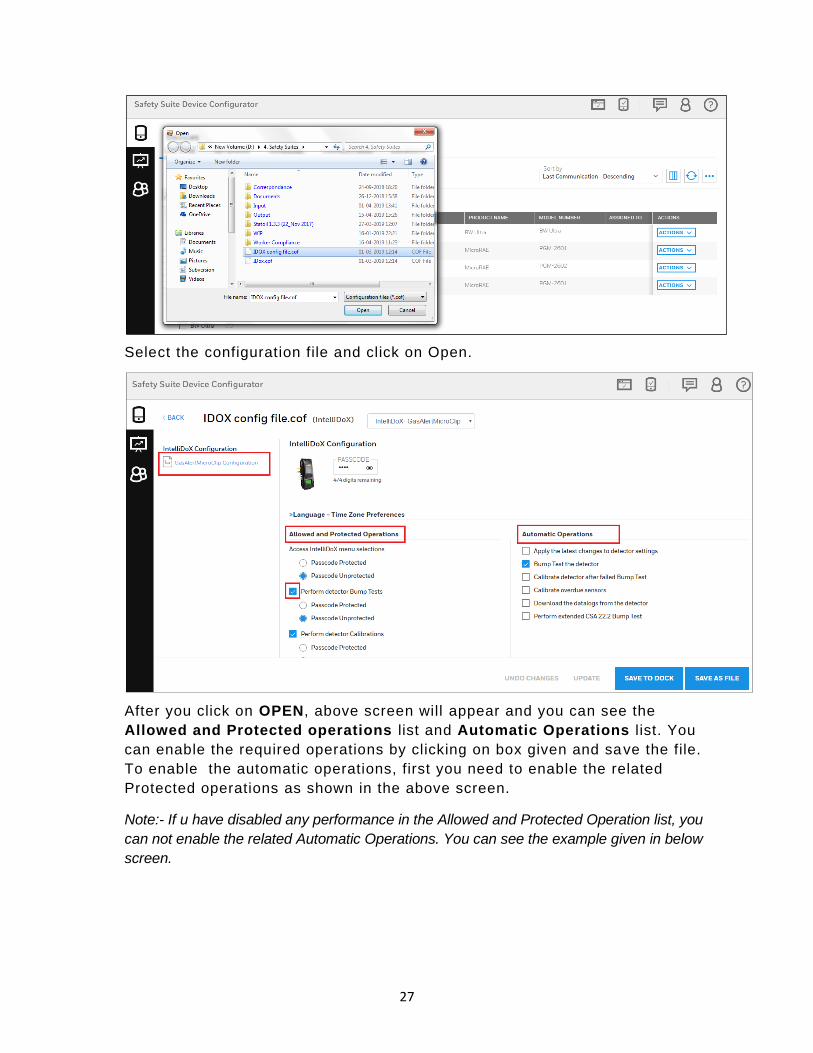
Select the configuration file and click on Open.
After you click on OPEN, above screen will appear and you can see the
Allowed and Protected operations list and Automatic Operations list. You
can enable the required operations by clicking on box given and save the file.
To enable the automatic operations, first you need to enable the related
Protected operations as shown in the above screen.
Note:- If u have disabled any performance in the Allowed and Protected Operation list, you
can not enable the related Automatic Operations. You can see the example given in below
screen.
28
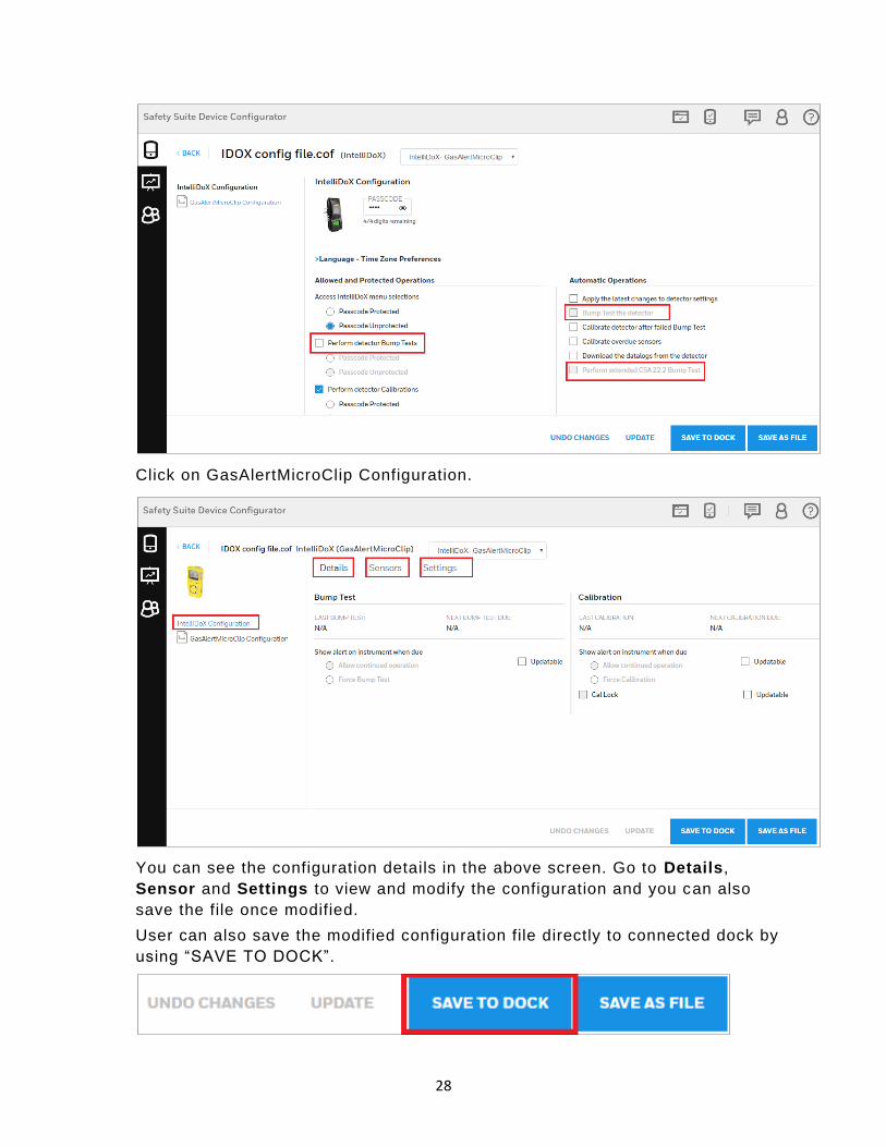
Click on GasAlertMicroClip Configuration.
You can see the configuration details in the above screen. Go to Details,
Sensor and Settings to view and modify the configuration and you can also
save the file once modified.
User can also save the modified configuration file directly to connected dock by
using “SAVE TO DOCK”.
29
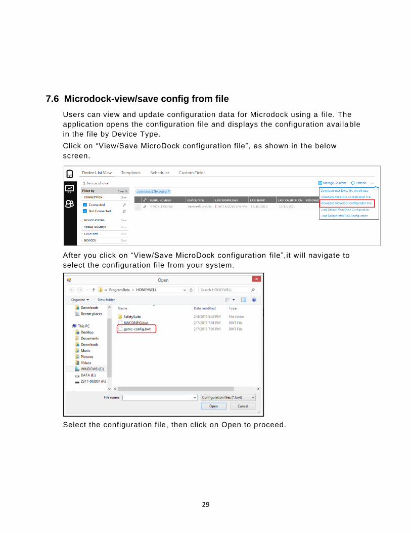
7.6 Microdock-view/save config from file
Users can view and update configuration data for Microdock using a file. The
application opens the configuration file and displays the configuration available
in the file by Device Type.
Click on “View/Save MicroDock configuration file”, as shown in the below
screen.
After you click on “View/Save MicroDock configuration file”,it will navigate to
select the configuration file from your system.
Select the configuration file, then click on Open to proceed.
30
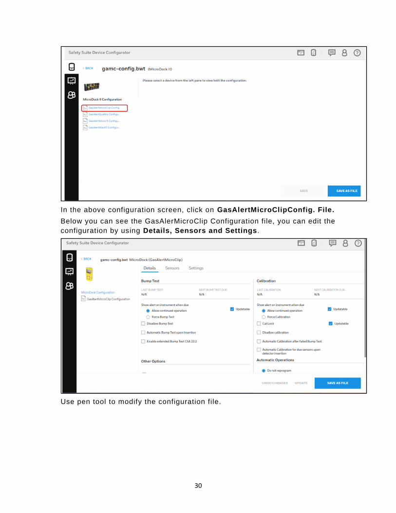
In the above configuration screen, click on GasAlertMicroClipConfig. File.
Below you can see the GasAlerMicroClip Configuration file, you can edit the
configuration by using Details, Sensors and Settings .
Use pen tool to modify the configuration file.

31
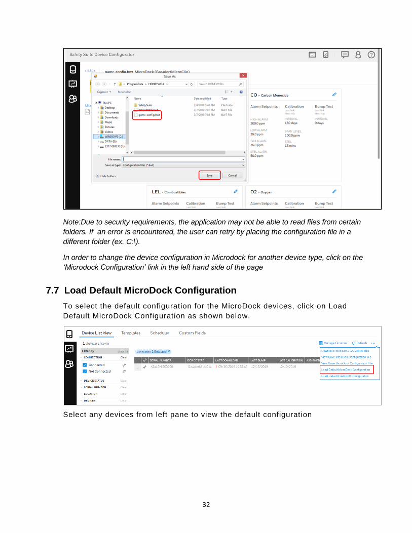
Below screen you can see the H2S gas configuration, Click on the update
check box to modify the settings and click on SAVE AS FILE to save the file.
Settings can be updated across sensors and devices. Once all changes are
completed the file can be saved at the user’s desired location.
32
Note:Due to security requirements, the application may not be able to read files from certain
folders. If an error is encountered, the user can retry by placing the configuration file in a
different folder (ex. C:\).
In order to change the device configuration in Microdock for another device type, click on the
‘Microdock Configuration’ link in the left hand side of the page
7.7 Load Default MicroDock Configuration
To select the default configuration for the MicroDock devices, click on Load
Default MicroDock Configuration as shown below.
Select any devices from left pane to view the default configuration
33
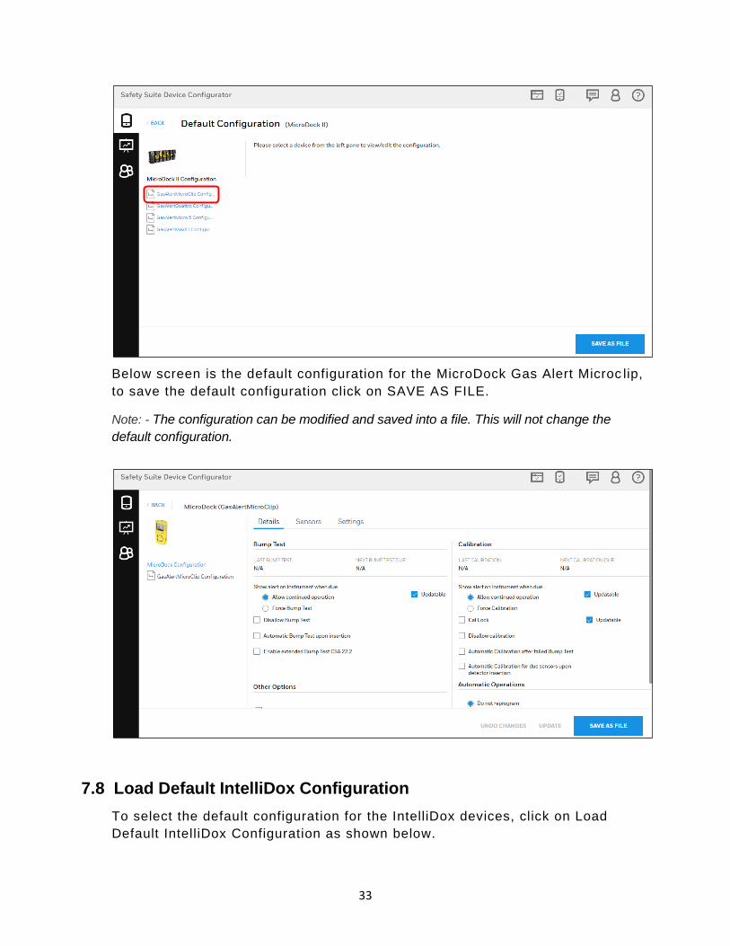
Below screen is the default configuration for the MicroDock Gas Alert Microc lip,
to save the default configuration click on SAVE AS FILE.
Note: - The configuration can be modified and saved into a file. This will not change the
default configuration.
7.8 Load Default IntelliDox Configuration
To select the default configuration for the IntelliDox devices, click on Load
Default IntelliDox Configuration as shown below.

34
Select any devices from left pane to view the default configuration
Below screen is the default configuration for the IntelliDox Gas Alert Microclip,
to save the default configuration click on SAVE AS FILE.
Here user can edit the configuration and create new configuration file or modify
the configuration and directly save that configuration to connected Dock.
35
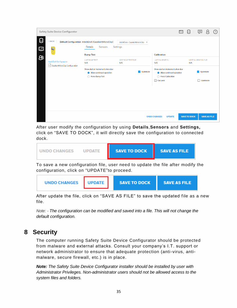
After user modify the configuration by using Details,Sensors and Settings,
click on “SAVE TO DOCK” , it will directly save the configuration to connected
dock.
To save a new configuration file, user need to update the file after modify the
configuration, click on “UPDATE”to proceed.
After update the file, click on “SAVE AS FILE” to save the updated f ile as a new
file.
Note: - The configuration can be modified and saved into a file. This will not change the
default configuration.
8 Security
The computer running Safety Suite Device Configurator should be protected
from malware and external attacks. Consult your company’s I.T. support or
network administrator to ensure that adequate protection (anti -virus, anti-
malware, secure firewall, etc.) is in place.
Note: The Safety Suite Device Configurator installer should be installed by user with
Administrator Privileges. Non-administrator users should not be allowed access to the
system files and folders.

36
8.1 Data Security
1. Make sure that the computer running Safety Suite Device Configurator is
properly configured if it is used on a LAN connected to an external network.
Firewalls and routers are configured to not drop required packet types (for
example, ICMP, SYN). This is to prevent external users from flooding the
internal network. Check with your local network administrator on how to
configure the firewall and router.
2. Have the local network administrator configure the local firewall or routers to
block all traffic from the RFC 1918 address space. Properly configuring
boundary protection devices like firewalls or routers prevents attackers from
using spoofed IP addresses that cannot be traced back.
3. Install anti-malware software on the computer.
4. Make sure any SD Card or USB memory drive connected to the machine that
accesses Safety Suite software is controlled and is scanned for Malware.
5. Log out of the application after the required actions in Safety Suite Device
Configurator are completed.
6. The Safety Suite Device Configurator installer/software is not decompiled or
modified.
8.2 Wireless Security Warning
Wireless data transmission by instruments and docking stations can extend
beyond your walls and can be received by anyone with a compatible adapter .
Without proper protection, data can be compromised. Use the security features
of all wireless equipment in your network.
Wireless devices typically have a default name and password. You should
change these to personalize them upon first installation, which decreases the
potential security risk that an unauthorized user can change the configuration .
IMPORTANT!
Other Wi-Fi devices may transmit specific Wi-Fi messages that interfere with
some wireless devices in a wirelessly networked system. You should not allow
any untrusted Wi-Fi transmitters inside the area of location and in its proximity
(approximately 50 meters).
9 Starting Safety Suite Device Configurator from the Desktop
With your computer and device connected via cable, you are ready to start
communication.
1. Follow the instructions in your monitor’s User’s Guide. This includes turning
the monitor on and making sure it is connected either directly via cable, or
through a cradle that is connected to the computer via a cable. Some
37
monitors automatically sense the computer and software, and place
themselves in communication mode. Check your instruments’ User’s Guide
for details.
2. Double-click the Safety Suite Device Configurator icon on your desktop to
start the program.
3. The program starts and a login dialog box appears:
Note: There are four access levels. The following sections cover the Administrator level,
since it has the greatest functionality. For more information on roles and access levels, refer
to page 39.
Enter the User Name and Password, and click “OK”.
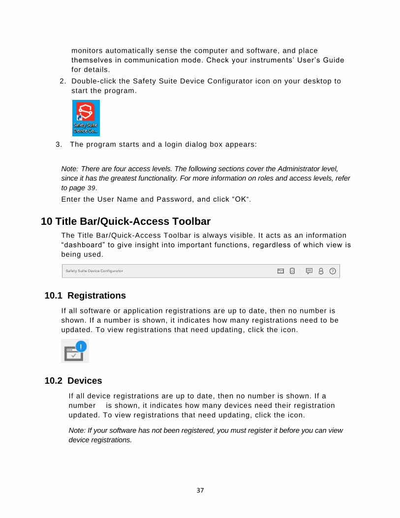
10 Title Bar/Quick-Access Toolbar
The Title Bar/Quick-Access Toolbar is always visible. It acts as an information
“dashboard” to give insight into important functions, regardless of which view is
being used.
10.1 Registrations
If all software or application registrations are up to date, then no number is
shown. If a number is shown, it indicates how many registrations need to be
updated. To view registrations that need updating, click the icon.
10.2 Devices
If all device registrations are up to date, then no number is shown. If a
number is shown, it indicates how many devices need their registration
updated. To view registrations that need updating, click the icon.
Note: If your software has not been registered, you must register it before you can view
device registrations.

38
10.3 Notifications
Notification shows, whether updates are being downloaded and its status. If a
number is shown, it indicates the number of downloads pending. If there is no
number and you click on the icon, a message says, “No download in progress”.
If a number is shown, click on the icon for details :
For more information, click “VIEW”:
If no download is in progress, there is no number on the icon, and if you click it,
this message is shown:
Note: When a download is in progress, performing an action with a device will not work.
However, you can perform other activities.
10.4 Role Information
Role Information provides insight and management of the current logged-in
user’s role and settings.

39
Click the icon to view the role’s name, as well as to Edit Profile, Sign Out,
review/change Settings, or view the User Role List.
10.4.1 Role Name
The Role Name tells you the role of the person logged in. Default values
include Standard User, Advanced User, Administrator, and Worker. Each user
must be assigned one or more roles. Click the appropriate box or boxes.
10.4.1.1 Role Names and Access Levels
The following definitions explain the four roles and their access:
• Administrator – Access to all the features of the application
• Advanced User – Access to all Device Management features and Reporting,
except User Management
• Standard User – Access to Data Download, Device History and Reporting.
• Worker – No access to any software features, only what are defined in the system
for tracking worker device assignments
10.4.2 Edit Profile
The profile includes details about the role/person currently logged in. Details
can be viewed and changed.

40
10.4.2.1 Update Profile Picture
Click the icon to open the dialog for uploading an image for the profile. The
image can be either a .jpg or .png file, but it must be less than 1MB.
To upload an image:
1. Click the blue button.
2. Click “Upload Photo.”
3. Locate an image on your computer and select it.
4. Click “Open.”
5. When the image appears, move it around with your mouse and/or change its
size by adjusting with the slide control.

41
6. When you are satisfied, click “Confirm”.
Note: Click “Cancel” if you decide not to change the picture, or “Remove” to remove an
existing picture.
10.4.2.2 Personal Information
View the personal information attached to this role. All aspects can be changed
except the username.
10.4.2.3 Change Password
You can change the password. You must supply the current password and then
type the new password. The password must follow these rules:
• The password must have a minimum of 8 characters.
• The password must include at least one character from all the following types:
✓ UPPERCASE
✓ lowercase
✓ Number: 0 1 2 3 4 5 6 7 8 9
✓ Special character, including: ! @ # $ % ^ * ( )
• The new password must not match any of the last five passwords that have been
used.
10.4.2.4 Update Security Questions
In case you forget your password and want to reset it, you will have to answer
security questions. Here is where you put the answers that must be matched if
you want to regain access after forgetting your password.
7. Select a security question from each pull-down list.
8. Type in an answer for each of the questions.
9. Click “Update.”
10.4.3 Sign Out
Click here to sign out.
Note: If you sign out, you will have to sign in again for access to Safety Suite Device
Configurator.

42
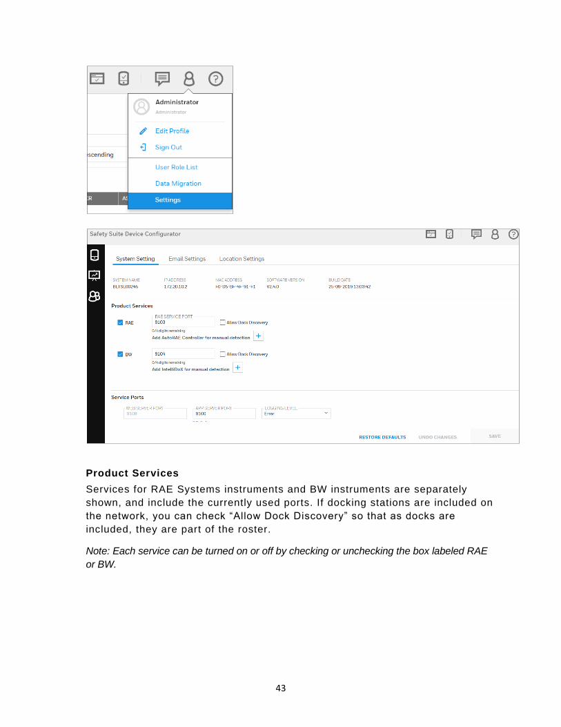
10.4.4 Settings
System Settings is an overview of the System Name, IP Address, MAC
Address, and Software Version. It also lists Product Services and Service
Ports.
Note: After you make changes to settings, you must go back to the Device list and select
“Manual Refresh.”
• Click “Save” to save any changes you make.
• Click “Undo Changes” to undo them.
• Click “Restore Defaults” to clear all changed values and revert to default values
that are supplied with the software.
Note:If you choose to restore default values, your customized settings are deleted and
cannot be retrieved.
10.4.4.1 System Settings
43
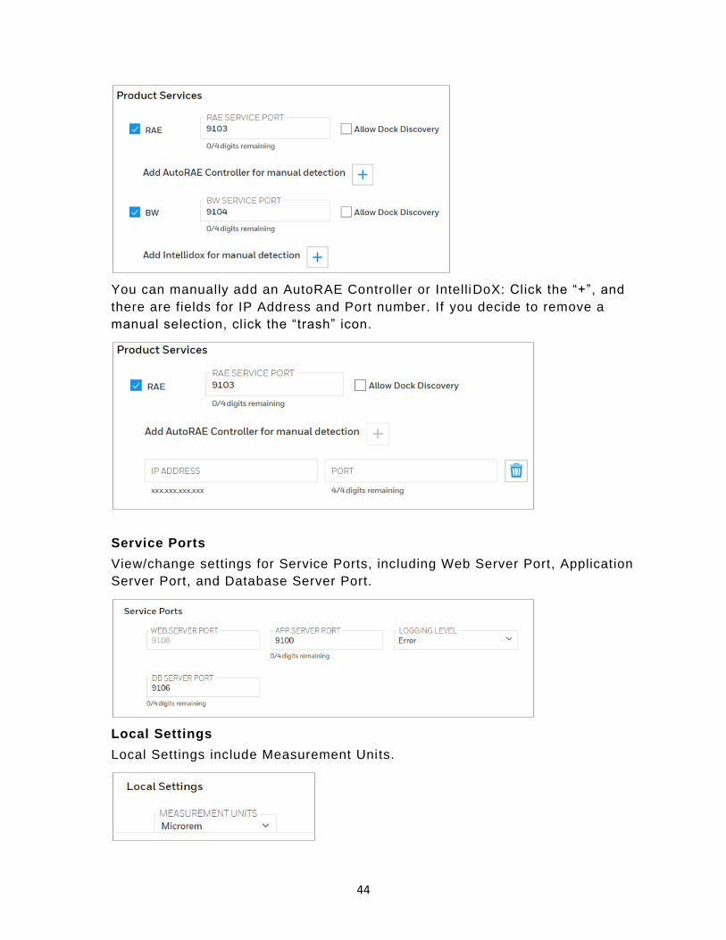
Product Services
Services for RAE Systems instruments and BW instruments are separately
shown, and include the currently used ports. If docking stations are included on
the network, you can check “Allow Dock Discovery” so that as docks are
included, they are part of the roster.
Note: Each service can be turned on or off by checking or unchecking the box labeled RAE
or BW.
44
You can manually add an AutoRAE Controller or IntelliDoX: Click the “+”, and
there are fields for IP Address and Port number. If you decide to remove a
manual selection, click the “trash” icon.
Service Ports
View/change settings for Service Ports, including Web Server Port, Application
Server Port, and Database Server Port.
Local Settings
Local Settings include Measurement Units.

45
10.4.4.2 Manage and Assign Locations
This will help to assign different location to different devices and docks. Follow
the below steps to Configure the Locations.
Configure the Locations.
Step 1: - Open Safety Suite Device Configurator and go to User profile and
click on Settings as shown in below screen.
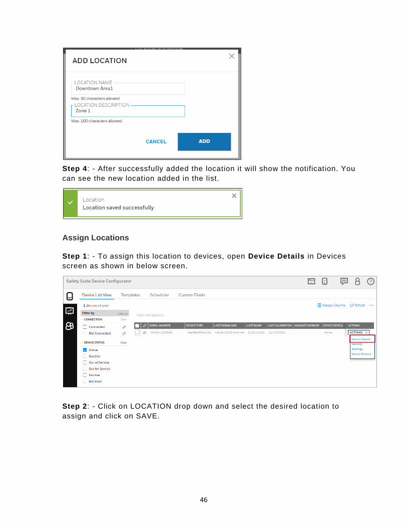
Step 2: - Click on ADD LOCATION.
Step 3: - Fill the required information in LOCATION NAME and LOCATION
DESCRIPTION, then click on ADD to save the location.
46
Step 4: - After successfully added the location it will show the notification. You
can see the new location added in the list.
Assign Locations
Step 1: - To assign this location to devices, open Device Details in Devices
screen as shown in below screen.
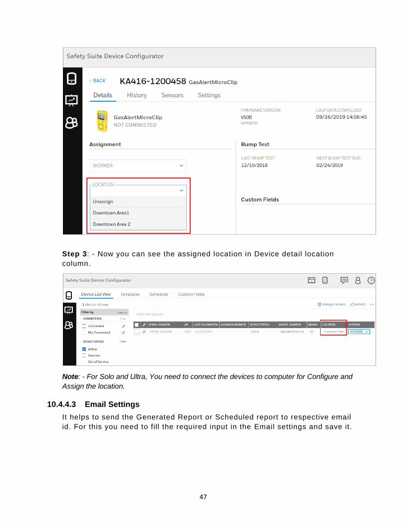
Step 2: - Click on LOCATION drop down and select the desired location to
assign and click on SAVE.
47
Step 3: - Now you can see the assigned location in Device detail location
column.
Note: - For Solo and Ultra, You need to connect the devices to computer for Configure and
Assign the location.
10.4.4.3 Email Settings
It helps to send the Generated Report or Scheduled report to respective email
id. For this you need to fill the required input in the Email settings and save it.

48
10.4.4.4 Network Settings
User can update the Firmware and software registration by using Network
settings.
Below you can see the network setting screen.
49
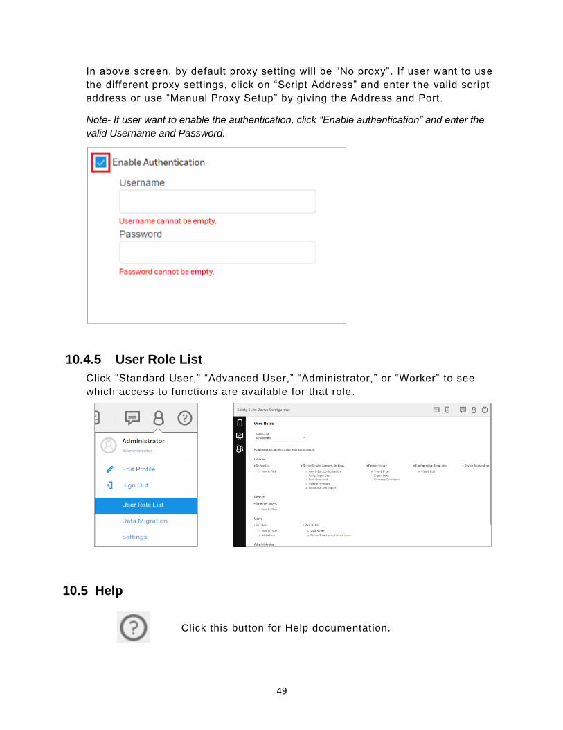
In above screen, by default proxy setting will be “No proxy”. If user want to use
the different proxy settings, click on “Script Address” and enter the valid script
address or use “Manual Proxy Setup” by giving the Address and Port.
Note- If user want to enable the authentication, click “Enable authentication” and enter the
valid Username and Password.
10.4.5 User Role List
Click “Standard User,” “Advanced User,” “Administrator,” or “Worker” to see
which access to functions are available for that role .
10.5 Help
Click this button for Help documentation.

50
11 Views
Safety Suite Device Configurator has two primary screens: Devices and User
List.
• Devices provides insight based on the devices in use.
• User List focuses on the users and the devices assigned to or associated with.
Devices view Generate Report view User List view
Here is the hierarchy of functions in Safety Suite Device Configurator:
11.1 Devices
When you select “Devices,” the main screen is shown with Devices selected, in
the List View.
List View Templates
Filter by: Connection Status Serial Number Devices Assigned To Last Communication First Communication Actions: Device Details Device History Archive Device
Filter By: Product Templates Actions: Edit Delete
Generate Report
Filter by: Status Name Device Assigned User Role Username Actions: User Details

51
11.1.1 Device Hierarchy
The relationship of instruments to docking stations and their controllers is
shown under “Product Name. ”
Note:This “parent/child” hierarchy is reflected in the “Filter by” section.
If a controller is connected to multiple docks or cradles, and if there are
multiple instruments, the hierarchy is extended to reflect the relationships.
Instruments that are not associated with a docking station or controller are
simply shown as individual list items.
The cradle or docking station is connected to
the controller.
The instrument is associated with the cradle
or docking station.

52
11.1.2 Manage Columns
Click “Manage Columns” to open a menu where you can select columns you
want to appear on the screen:
A check mark in a box indicates that you have selected this column to be
shown. Boxes/names in light gray indicate that their visibility cannot be
changed.
11.1.3 Refresh
Click Refresh to update the information on the screen. It is important to do this
whenever you connect a new device to the computer running Safety Suite
Device Configurator.
11.1.4 List View
When the list of instruments is shown, you can manage it in a variety of ways
using filters.
At the top, the total number of devices shown is indicated. Also indicated is the
number of filters, shown by filter category.

53
12 Assign Device to Worker
Device view allows you to assign the device to the worker, the device only
assigns with the user which has Worker Role defined, for more info rmation
about defining Roles refer section Role Name.
To Assign the device to a worker.
1. Go to the “Device” from main screen menu .
2. Switch to “List View” and “Clear Filer” to view all devices
3. Select the Device that needs to be assign to the worker.
4. Click on the “Action” dropdown list and select “Device Details”.
5. Select the registered Worker’s Name from Assignment dropdown list.

54
6. Click on “Save” to changed Settings.
Note: Multiple device can be assign to a single worker, but single device cannot be assigned
to more than one person.
13 Filter by
Several filters are included so that you can expand or pare down the data. This
is especially valuable when you are managing many instruments.
Filters include:
• Connection
• Device Status
• Serial Number
• Location
• Devices
• Assigned Worker
• Last Download
• Last Bump
• Last Calibration
As filters are selected, they are shown above the list, and the list updates to
reflect your choices. You can remove a filter directly in the “Filter by” menu or
by clicking the “x” in a filter shown above the list.

55
13.1 Connection
Click “Connected” or “Not Connected,” or both to include instruments that are
connected to the PC running Safety Suite Device Configurator and those in the
roster that are not connected.
Status
Click “Archived” to see any instruments that are archived.
Serial Number
Search for devices by serial number. Type in the serial number of a device in
the roster, or select from the list that appears when you start typing or mouse
over the box.
Your choice is shown in the box.

56
You can select multiple serial numbers, too:
Your choice is shown in the list, along with indication of how many devices are
shown:
You can clear all the selections by clicking “Clear” or you can select which ones
you want to clear by clicking on the “X” in an individual tag.
13.2 Devices
Two choices of devices are available: Instruments and Docks. You can select
all instruments or all docks (docking stations) by clicking Instruments or Docks,
57
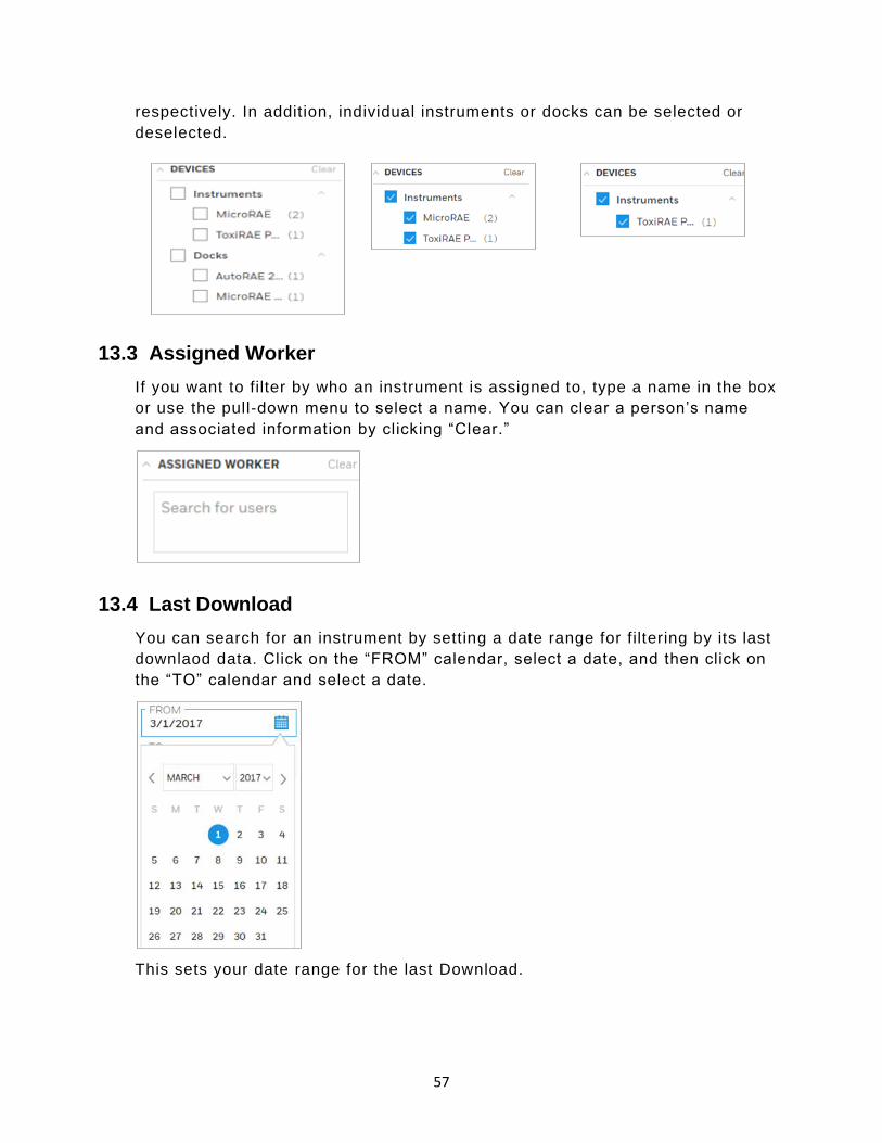
respectively. In addition, individual instruments or docks can be selected or
deselected.
13.3 Assigned Worker
If you want to filter by who an instrument is assigned to, type a name in the box
or use the pull-down menu to select a name. You can clear a person’s name
and associated information by clicking “Clear.”
13.4 Last Download
You can search for an instrument by setting a date range for filtering by its last
downlaod data. Click on the “FROM” calendar, select a date, and then click on
the “TO” calendar and select a date.
This sets your date range for the last Download.

58
Click “Clear” to clear the selected “TO” and “FROM” dates.
13.5 Last Bump
You can search for an instrument by setting a date range for filtering by its Last
Bump. Click on the “FROM” calendar, select a date, and then click on the “TO”
calendar and select a date.
This sets your date range for the first communication.
Click “Clear” to clear the selected “TO” and “FROM” dates.
13.6 Last Calibration
You can search for an instrument by setting a date range for filtering by its Last
Calibration. Click on the “FROM” calendar, select a date, and then click on the
“TO” calendar and select a date.

59
This sets your date range for the first communication.
Click “Clear” to clear the selected “TO” and “FROM” dates.
13.7 Device Status
Filter the Devices by using “Device Status”, click on Device Status Dropdown
and you will see the below screen. Click on the check box to select the status
and if you want to update the device status, please refer Set Parameters.
14 Device List View
User can view the list of devices under Device List view. For each device/dock
Serial number, Model number, Device type, Assigned worker, Last Download,
Last Bump, Last calibration, Asign Worker, Location and status of devices can
be viewed for both Offline and Online.

60
Note- User can add/remove fields using the 'Manage Columns' option .
To perform actions such as Download data, view Bump/Cal results, view Event
and Data logs, user can select the devices from the device list. Click on
checkbox to select the devices, as shown below. After you select the devices,
all the quick actions will be highlighted on the screen.
Below screens are for single and multi device selection.

61
14.1 Download data
To download data from online devices, select the devices on Device inventory
screen, then click on hilighted to strat the download process.
After you click on Download Data, notificaton will pop up on screen saying
“Data download started”
14.2 Set Parameters
You can qickly set the parameters like Status and Location for the devices by
clicking on .

62
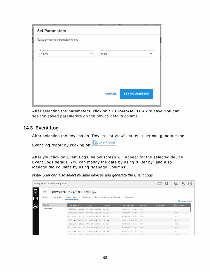
After you click on the Set Parameter it will navigate to the below screen.
Select the Status and Location by clicking the drop down.
63
After selecting the parameters, click on SET PARAMETERS to save.You can
see the saved parameters on the device details colums.
14.3 Event Log
After selecting the devices on “Device List View” sc reen, user can generate the
Event log report by clicking on .
After you click on Event Logs, below screen will appear for the selected device
Event Logs details. You can modify the date by using “Filter by” and also
Manage the columns by using “Manage Columns”.
Note- User can also select multiple devices and generate the Event Logs.
64
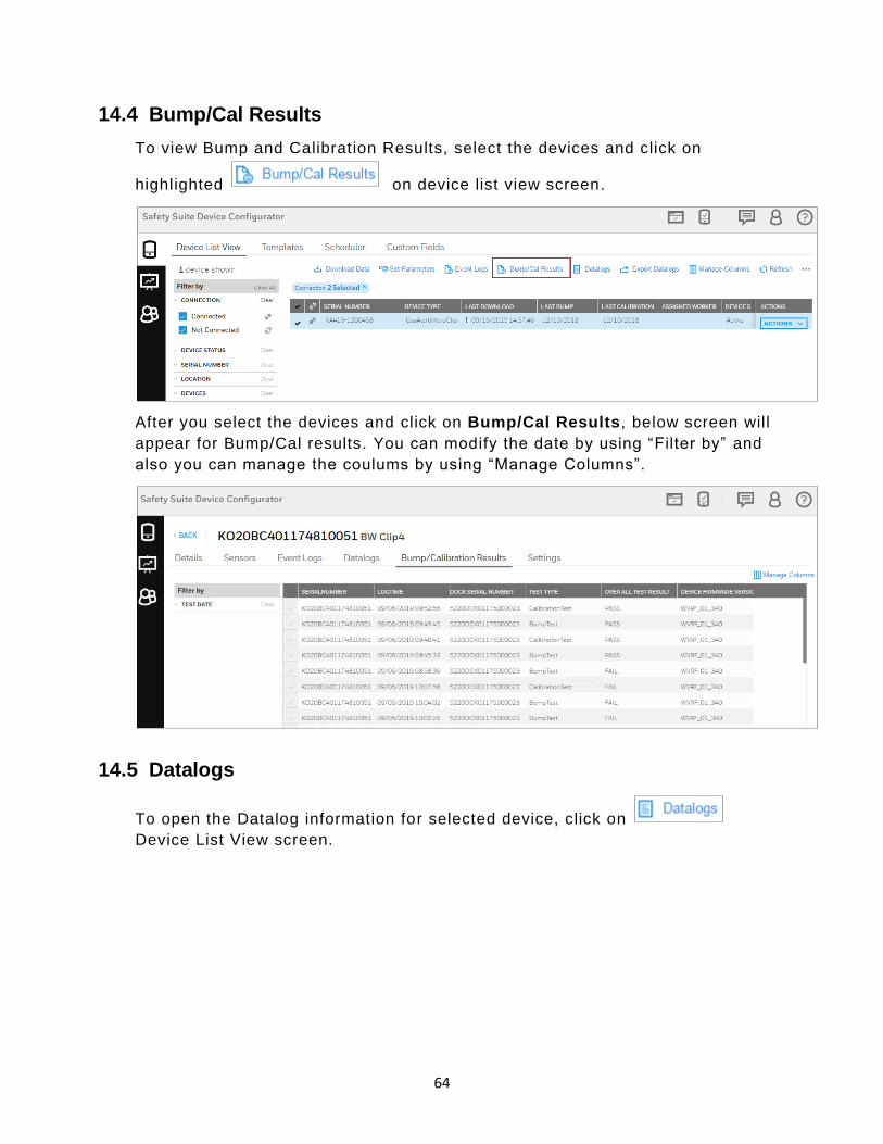
14.4 Bump/Cal Results
To view Bump and Calibration Results, select the devices and click on
highlighted on device list view screen.
After you select the devices and click on Bump/Cal Results, below screen will
appear for Bump/Cal results. You can modify the date by using “Filter by” and
also you can manage the coulums by using “Manage Columns”.
14.5 Datalogs
To open the Datalog information for selected device, click on
Device List View screen.

65
You can see the Datalogs information on below screen. Modify the Date and
Columns by using “Filter by” and “Manage Columns”.
15 Actions
Actions consist of things you can do with each device’s data.
15.1 Device Details
Device Details include details of the device, including history, i nstalled sensors,
and settings.
To view the device details in Devices, List View click on ACTIONS drop down list, then click
on “Device Details”.

66
In device details user can view current Firmware Version of the device or
update latest version if available, view or schedule Bump Test and Calibration
of the device, user can also updated/change the device assigned worker and
location of the device.
Once all the fields are filled and selected, click on SAVE to update the
changes.
15.1.1 Instruments
Instruments such as gas monitors are profiled with details of bump tests,
calibration, assignment, and connection with cradles and controller s. You can
update the firmware, check history, sensors, and settings, and make/save
changes.

67
Note: If an instrument is not currently connected to the computer, under Details it says, “Not
Connected-View Only”. This tells you that you cannot change settings or perform updates.
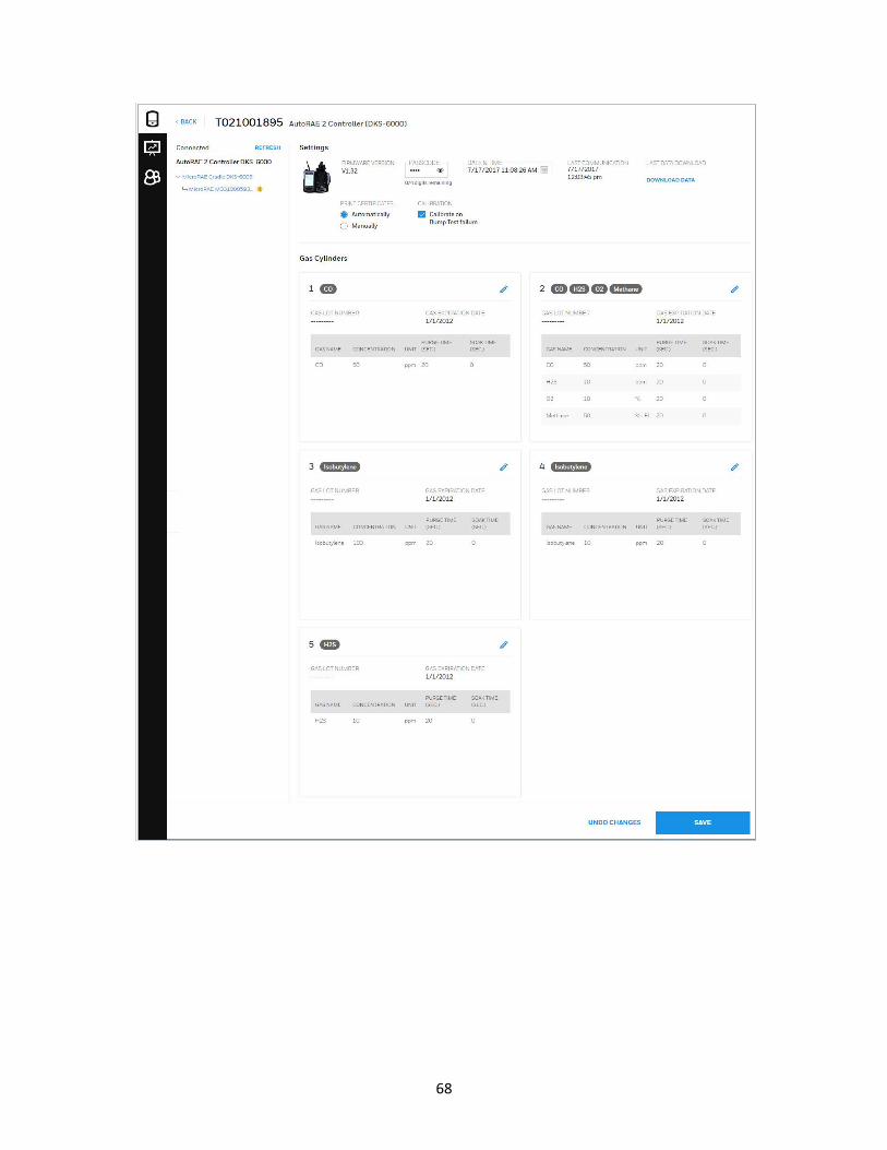
15.1.2 Docking Stations
Device Details for a docking station include information about gases, as well as
settings. In addition, you can update the firmware version, set the Menu
passcode, set date and time, and download data. You can also print calibration
certificates either automatically or manually and tell the docking s tation to
calibrate instruments if they fail a bump test.
68

69
15.1.2.1 Menu Passcode
Menu Passcode is required to access the settings menu in the physical
IntelliDoX Device.
Note: User can not Set or Update/Modify Menu passcode from IntelliDoX device and can
only enter this passcode to authenticate to access the IntelliDoX settings menu. The user
can View or Set/Update the passcode from Device Configurator.
15.1.2.2 Edit Gas Cylinder Configuration
To edit a gas cylinder’s configuration, click the “Edit” icon:
The configuration window is shown, and you can make changes to the Lot
Number, Expiry (expiration date), the gas, and its attributes.

70
Important!
If you change any details of the configuration’s gases, make sure they match
the information printed on the gas cylinder. This is especially crit ical for the
Gas Type, Concentration (and units, such as ppm), Lot Number and Expiry
date.
Add another gas (if this is a multi-gas mix) by clicking the “+” icon. Then add
the details of the new gas.
If you want to remove a gas from the list, click the “Delete” icon:
When you are done with the configuration, click “SAVE.” If you do not want to
save these changes, click “Undo Changes”.
15.2 Device History
71
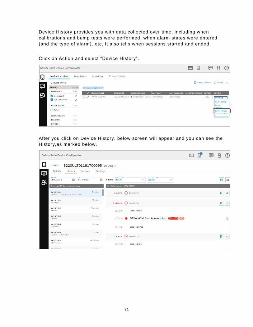
Device History provides you with data collected over time, including when
calibrations and bump tests were performed, when alarm states were entered
(and the type of alarm), etc. It also tells when sessions started and ended.
Click on Action and select “Device History”.
After you click on Device History, below screen will appear and you can see the
History,as marked below.
72
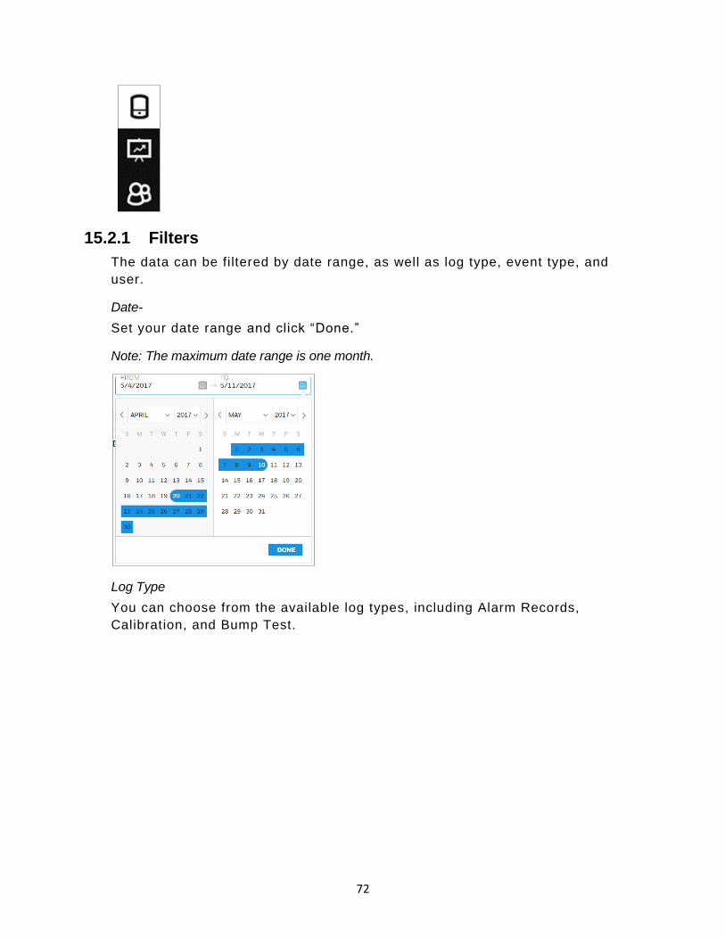
15.2.1 Filters
The data can be filtered by date range, as well as log type, event type, and
user.
Date-
Set your date range and click “Done.”
Note: The maximum date range is one month.
Log Type
You can choose from the available log types, including Alarm Records,
Calibration, and Bump Test.

73
Click on the Gas alarm and you can see the UNIT STATUS and Sensor details
in perticuler alarm.
To see the UNIT STATUS, Move your cursor on below marked time stamp.
To see the Sensor details, Move your cursor on below marked sensor unit.

74
Event Type
Filter according to the type of event that is of interest.
Users
Filter according to the names of users.
Summaries
There are two ways to view summaries of a device’s history.
Summary for The Day opens a window with all the day’s
session information, organized by session.
Export Day Info opens a window that lets you choose data
elements and summary information and then export it. You can
print it or save it as a CSV file for opening in a spreadsheet
program such as Microsoft Excel.
Log
To view a log of a device, click the arrow icon at the right of the column:

75
This opens the Log window for viewing.
You can also view information about the session and calibration details:
Export
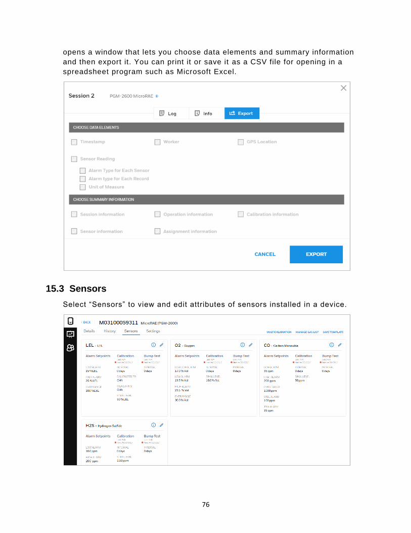
76
opens a window that lets you choose data elements and summary information
and then export it. You can print it or save it as a CSV file for opening in a
spreadsheet program such as Microsoft Excel.
15.3 Sensors
Select “Sensors” to view and edit attributes of sensors installed in a device.
77
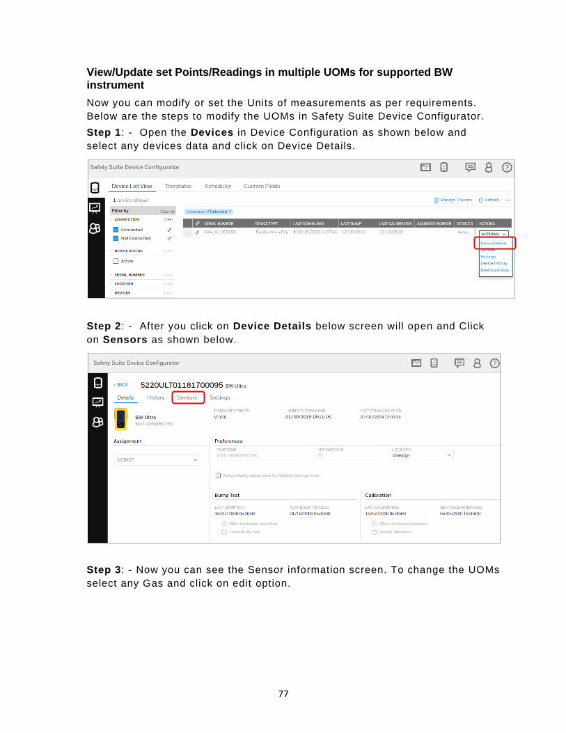
View/Update set Points/Readings in multiple UOMs for supported BW instrument
Now you can modify or set the Units of measurements as per requirements.
Below are the steps to modify the UOMs in Safety Suite Device Configurator.
Step 1: - Open the Devices in Device Configuration as shown below and
select any devices data and click on Device Details.
Step 2: - After you click on Device Details below screen will open and Click
on Sensors as shown below.
Step 3: - Now you can see the Sensor information screen. To change the UOMs
select any Gas and click on edit option.

78
Step 4: - Below screen is the edit screen information for CO gas, you can
change the UOMs by clicking on DISPLAY UNITS dropdown. Select the
required Units and save the file.
15.4 Settings
View and manage settings in a device. You can save these as a file or as a
template.

79
15.5 Archive Device
Click this choice to de-assign a device from a user and make it invisible to the
default device list.
15.6 Network Passcode
The Network Passcode is required to access IntelliDoX to perform any ACTION,
the passcode is defined to access and operate or change setting in IntelliDoX
over the network.

80
Network Passcode is applicable/available on IntelliDoX device having firmware
9.0 and above only.
Note: The user can not Set or Update/Modify passcode from Device Configurator and can
only enter this passcode to authenticate and access the IntelliDoX to perform any
ACTION.The user can View or Set/Update the Network passcode in IntelliDoX Device.
16 Custom fields in Device Configurator
User can add new Custom fields (User defined fields) to capture additional
information about devices.
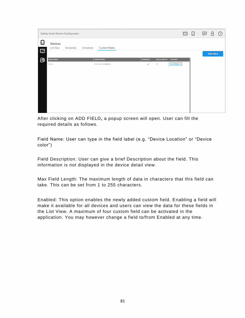
To add new Custom fields, Open the Devices tab and click on “Custom fields”
then you can see the “ADD FIELD” option to add the new Custom field.
81
After clicking on ADD FIELD, a popup screen will open. User can fill the
required details as follows.
Field Name: User can type in the field label (e.g. “Device Location” or “Device
color”)
Field Description: User can give a brief Description about the f ield. This
information is not displayed in the device detail view.
Max Field Length: The maximum length of data in characters that this field can
take. This can be set from 1 to 255 characters.
Enabled: This option enables the newly added custom field. Enabling a field will
make it available for all devices and users can view the data for these fields in
the List View. A maximum of four custom field can be activated in the
application. You may however change a field to/from Enabled at any time.
82
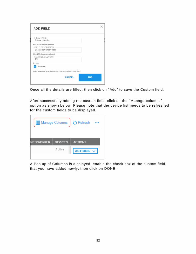
Once all the details are filled, then click on “Add” to save the Custom field.
After successfully adding the custom field, click on the “Manage columns”
option as shown below. Please note that the device list needs to be refreshed
for the custom fields to be displayed.
A Pop up of Columns is displayed, enable the check box of the custom field
that you have added newly, then click on DONE.

83
To view the newly added custom field scroll the grid coulmn towards right -end
side.
To view or edit the custom field values for a specific instrument, click on the
“Action” dropdown list and select “Device Details”.

84
After clicking on “Device Details” below screen will open and enter the custom
field value and click on SAVE.
Now open the Device view and click on “List view”, the below screen you can
see the value for custom field that you updated.

85
17 Scheduled data import
User can Schedule automatic import/download data from docking stations.
Below are the steps to be followed to set up the scheduled data import.
Step 1- Click on “Devices” icon and select the “Scheduler” option to set the
time.
Note-Before making your selection, please refresh the docking station
connectivity status by clicking the refresh button.
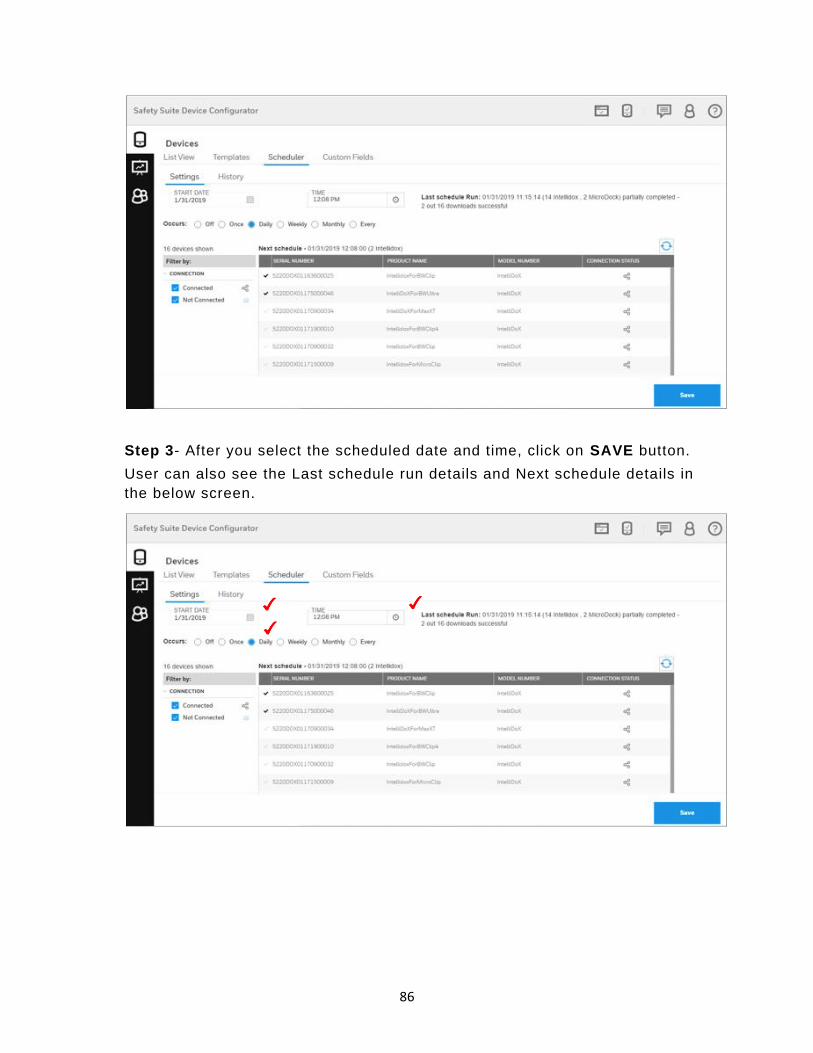
Step 2- Set the START DATE and TIME by clicking on the Settings tab and
select the OCCURS options when user want to run the download.
Note-Make sure Schedule Start Date Time should be greater than current date time.
86
Step 3- After you select the scheduled date and time, click on SAVE button.
User can also see the Last schedule run details and Next schedule details in
the below screen.

87
Step 4- When scheduled time approaches, it will show the scheduled progress
details and if user want to cancel the scheduled progress, click on cancel
button.
Step 5- After completing the scheduled run process, click on History and check
the scheduled run status. User can also check the older data details by
changing the Date Range option.
Step 6- If user want to export the data, click on below shown red marked box
and export the data to CSV file.
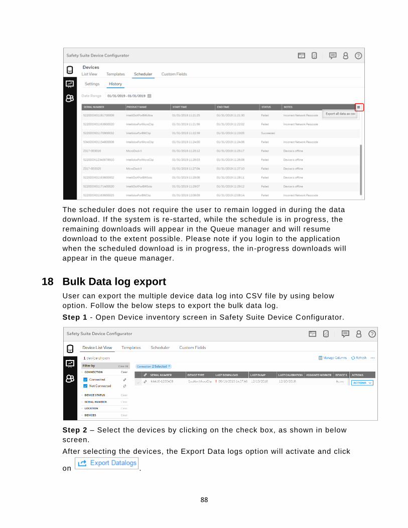
88
The scheduler does not require the user to remain logged in during the data
download. If the system is re-started, while the schedule is in progress, the
remaining downloads will appear in the Queue manager and will resume
download to the extent possible. Please note if you login to the application
when the scheduled download is in progress, the in-progress downloads will
appear in the queue manager.
18 Bulk Data log export
User can export the multiple device data log into CSV file by using below
option. Follow the below steps to export the bulk data log.
Step 1 - Open Device inventory screen in Safety Suite Device Configurator.
Step 2 – Select the devices by clicking on the check box, as shown in below
screen.
After selecting the devices, the Export Data logs option will activate and click
on .

89
Step 3 – Below you can see the Export Datalogs screen.
Step 4 – Select the date range by clicking on the DATE RANGE tab, as shown
below.

90
Step 5 – Click on Browse and select the location to save the CSV file.

91
Step 6 – After selecting the location, click on EXPORT CSV. The notification
will pop up on screen saying “Datalog export started successfully”.
Step 7 – Wait for the export to complete. You can check the status in the
notification area.
Step 8 – Go to selected location and open the generated CSV file.
Now you can see the CSV file below.
19 User List
The User List shows all users registered with Safety Suite Device
Configurator, regardless of whether they are Active Users, Locked Users, or
Deactivated Users. The roster can be filtered in a variety of ways for
organization or searching.

92
19.1 Sort by
Use this pulldown menu to sort your templates for quicker searching, greatest
current relevance, or other ways that suit your workflow.
Username – Ascending
Phone Number – Descending
Phone Number – Ascending
Username – Descending
Email – Descending
Email – Ascending
User Role – Descending
User Role – Ascending
Device Assigned – Descending
Device Assigned – Ascending
Name – Descending
Name – Ascending
19.2 Manage Columns
Click “Manage Columns” to open a menu where you can select columns you
want to appear on the screen:
Click a box to show a check mark, which indicates that you have selected this
column to be shown. Boxes/names in light gray indicate that their visibility
cannot be changed. When you have finished with your selections, click “Done”
to save your choices or “Cancel” to keep your current choices.

93
19.3 Actions
Depending on the user’s role, actions can include User Details, Activate User
(or Deactivate User), or Delete User.
User Details is the default view. It shows each user according to filter settings,
as well as all details defined in the Columns settings.
Activate User/Deactivate User gives control over who can be considered an
active user. An active user is someone who has access to a device, whereas a
deactivated user is not granted access (whether temporarily or permanently). A
deactivated user can be re-activated.
Delete User is where you remove a user from the roster, such as when an
employee leaves a company, is transferred elsewhere, etc. Note: If a user is
deleted, their profile is deleted. This is permanent, so you cannot restore a
deleted user to an active user status.
19.4 Add A User
Click the “+” button to open a page where you fill in information and create the
profile for a new user.

94
You must provide a First Name, Last Name, Email address, and Username,
plus you must select a role (or roles). All other information is optional. Once
you have provided the necessary information and selected a role, “Add” is
highlighted. Click this to add the new user to the roster. If you do not want to
save it, click “Cancel.”
After you add a new user, a message is shown that tells you the new user must
provide an activation code during their first login.
19.5 Profile Picture
Click the icon to open the dialog for uploading an image for the profile. The
image can be either a .jpg or .png file, but it must be less than 1MB.
To upload an image:
95
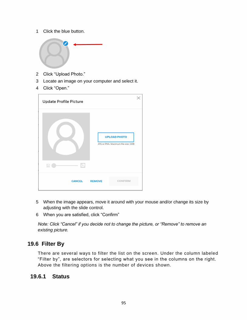
1 Click the blue button.
2 Click “Upload Photo.”
3 Locate an image on your computer and select it.
4 Click “Open.”
5 When the image appears, move it around with your mouse and/or change its size by
adjusting with the slide control.
6 When you are satisfied, click “Confirm”
Note: Click “Cancel” if you decide not to change the picture, or “Remove” to remove an
existing picture.
19.6 Filter By
There are several ways to filter the list on the screen. Under the column labeled
“Filter by”, are selectors for selecting what you see in the columns on the right.
Above the filtering options is the number of devices shown.
19.6.1 Status

96
The status of a user can be used as a filter, so that, for example, only active
users are included in the list, or only deactivated users are shown. You can
clear a status type and associated information by clicking “Clear” or the “X” in
the “Status” above the list.
Active Users
An active user is one who is in the current roster of users who can participate
in the system’s use, and is associated with a role and an instrument. An active
user’s status can be changed to “deactivated” or the user can be deleted from
the roster.
Note: If you delete a user, the data cannot be recovered.
Locked Users
As a security feature, if a user tries to log in and provides an incorrect
password three times, they are locked out and must contact the administrator to
restore access.
When logging in, if an incorrect password is provided twice, this message is
shown:
If three attempts are incorrect, then the user is locked out. This message is
shown:

97
Someone with administrator privileges can unlock the user’s status by pulling
down the “Actions” menu and clicking “Unlock User.”
This message is shown:
Click “Unlock” to unlock the user’s status.
Deactivated Users
A deactivated user has a profile but is not included in the active roster. A
deactivated user’s status can be changed to “active” or the user can be deleted
from the roster.
Note:If you delete a user, the data cannot be recovered.
19.6.2 Name
Search for a user in the User List by name. Either type in a name or select one
of the names in the list.
If a match is made, the person’s name is then shown in the box:

98
You can add multiple names to the filter by clicking in the box again and
selecting a name. The name appears below the previously selected name.
• Click “Clear” to clear all names.
• Click “X” next to a person’s name to clear them from the list.
If you type a name and there is no match, then “No matches found” is shown.
As names are added to the filter, corresponding rows to the right are filled with
each person’s information. The columns are determined by the Columns
setting.
19.6.3 Device Assigned
Filter by devices that are assigned or unassigned, or to see all (regardless o f
assignment), click both boxes.
19.6.4 User Role
Each user must be assigned one or more roles. Click the appropriate box or
boxes.
99
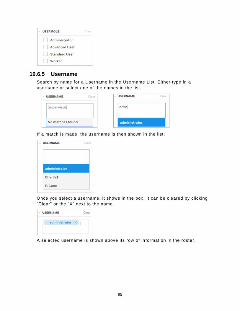
19.6.5 Username
Search by name for a Username in the Username List. Either type in a
username or select one of the names in the list.
If a match is made, the username is then shown in the list:
Once you select a username, it shows in the box. It can be cleared by clicking
“Clear” or the “X” next to the name.
A selected username is shown above its row of in formation in the roster.

100
19.7 Download/Upload Bulk User Import File
Now users can import the file into Safety Suite Device Configurator in bulk by
using an excel template. Follow the below steps to Download and upload the bulk user file.
Download Bulk User Import Template
Step 1: - Open Safety Suite Device Configurator and click on USER LIST from
side menu bar.
Step 2: - In USER LIST screen click on Option tab as sown in below screen and
select Download Bulk User Import Template to download the templates file.

101
Step 3: - After u click on Download Bulk User Import Template, below screen
will open to save the file at user desired location.
Select the location to save the file and click on Save.
Step 4: - Go to the location where you saved the file and open it.
Now you can see the User information sheet template. Fill the required input in
all the columns and save the file.
Note: - Before you fill the information please read ReadME sheet in excel(Sheet1).
Upload Bulk User Import Template
Step 1: - Click on Upload Bulk User Import file in user list option as shown in
below screen.

102
Step 2: - After you click on Upload Bulk User Import file, below screen will
open to select the downloaded template file.
Step 3: - Click on BROWSE option and select the User information file from
saved location.
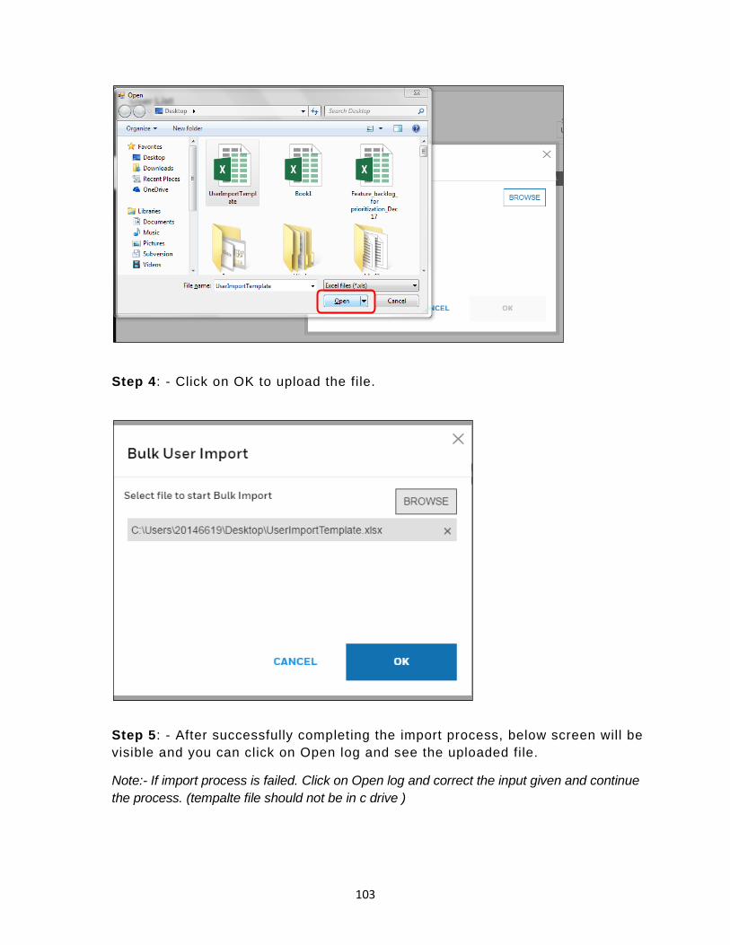
103
Step 4: - Click on OK to upload the file.
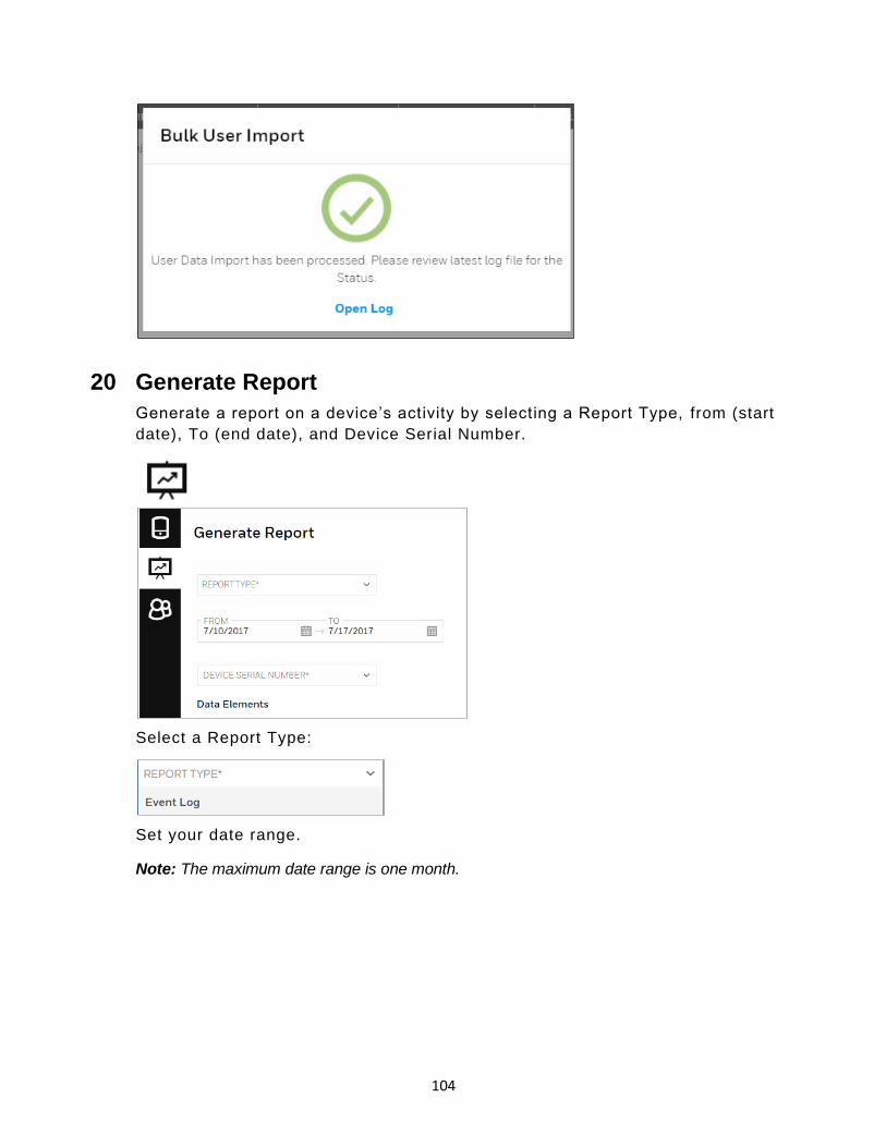
Step 5: - After successfully completing the import process, below screen will be
visible and you can click on Open log and see the uploaded file.
Note:- If import process is failed. Click on Open log and correct the input given and continue
the process. (tempalte file should not be in c drive )
104
20 Generate Report
Generate a report on a device’s activity by selecting a Report Type, from (start
date), To (end date), and Device Serial Number.
Select a Report Type:
Set your date range.
Note: The maximum date range is one month.

105
Next, select a device’s serial number, followed by the Data Elements you want
to include. Two can be selected or de-selected.
Click “Generate” to create a report based on your criteria.
Note:If you click “Reset”, it clears all fields.
When the Event Log Report is created, an alert appears, telling you that an
event log report has been generated and is available. Click “OPEN” to view it.

106
The Event Log Report can be printed or exported to PDF format for later
reference, emailing, etc.
Note: The Event Log Report shows as a single page on the screen, but it is typically longer
than one page (the scroll bar along the right side indicates multiple pages’ worth of data).
Therefore, if you are printing, make sure your printer has adequate paper to accommodate
the document.
When you are done, click the “X” in the upper right corner to close the window.
20.1 Multidevice reports-Eventlog(Multidevice event report)
User can generate the gas alarm report for the multiple devices.
Below are the steps to follow how to generate multidevice event report.
Step1- Open “Generate report” view in Safety Suite Device Configurator and
select the “Create report” option to create the report.
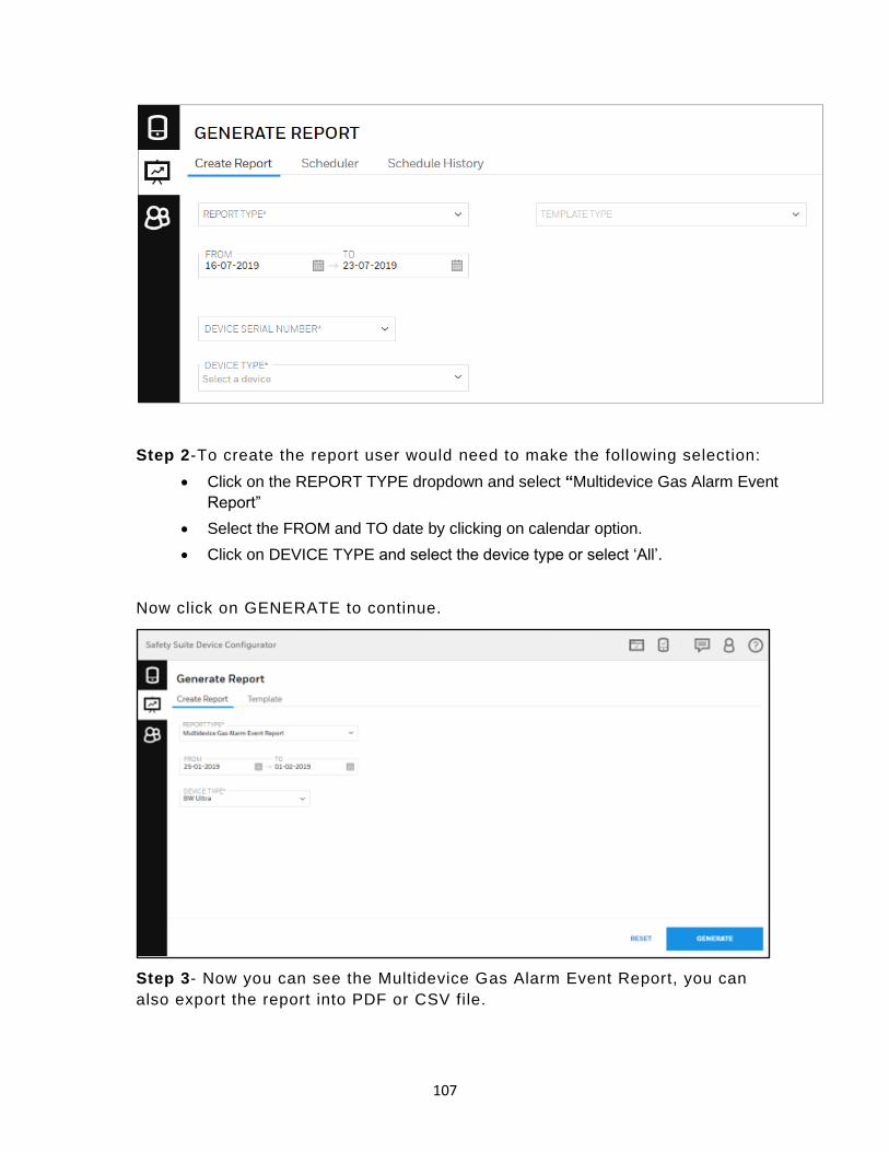
107
Step 2-To create the report user would need to make the following selection:
• Click on the REPORT TYPE dropdown and select “Multidevice Gas Alarm Event
Report”
• Select the FROM and TO date by clicking on calendar option.
• Click on DEVICE TYPE and select the device type or select ‘All’.
Now click on GENERATE to continue.
Step 3- Now you can see the Multidevice Gas Alarm Event Report, you can
also export the report into PDF or CSV file.

108
20.2 Custom Report
You can customize the generating report by creating the new template and you
can also get the report through mail.
20.2.1 Create Custom Report
To create the report, Open “Generate report” view in Safety Suite Device
Configurator and select the “Create report”.
In the above screen, you need to fill the required parameters.
• Click on the REPORT TYPE dropdown and select the report type.
• Select the FROM and TO date by clicking on calendar option .
• Click on DEVICE TYPE and select the device type.

109
• Click ok TEMPLATE TYPE dropdown and select the template.
Click on GENERATE to continue.
20.2.2 Template type
When you are creating the Custom Report, you can select the template by
clicking on TEMPLATE TYPE dropdown and select Default template or Create
new template.
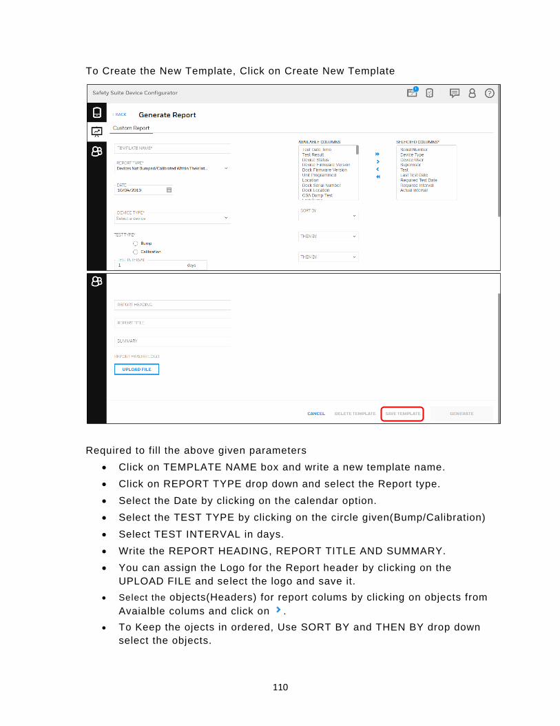
110
To Create the New Template, Click on Create New Template
Required to fill the above given parameters
• Click on TEMPLATE NAME box and write a new template name.
• Click on REPORT TYPE drop down and select the Report type.
• Select the Date by clicking on the calendar option.
• Select the TEST TYPE by clicking on the circle given(Bump/Calibration)
• Select TEST INTERVAL in days.
• Write the REPORT HEADING, REPORT TITLE AND SUMMARY.
• You can assign the Logo for the Report header by clicking on the
UPLOAD FILE and select the logo and save it.
• Select the objects(Headers) for report colums by clicking on objects from
Avaialble colums and click on .
• To Keep the ojects in ordered, Use SORT BY and THEN BY drop down
select the objects.

111
After completing the all parameters, Click on SAVE TEMPLATE to save the
template.
20.2.3 Scheduler
User can schedule a Report and Datalog by following below steps.
Open Scheduler in Safety Suite Device Configurator, as shown below.
Click on CREATE SCHEDULE and it will navigate to below screen.
You can see two type of Schedule in above screen,
1. Report.
2. Datalog
1. Schedule Report and Email Notification
Follow the below steps to Schedule a Report and Email notification.
Step 1- Click Report from Schedule type.

112
Step 2- After you click on Report, below screen will appear and you need to
select the below required input.
• Report Type
• Select Template(Default or Custom Template)
• Schedule Start Date and Time
• Set Recurrence(Off, Once, Weekly and Monthly)
Step 3- In below screen, User can receive report details through Email by using
REPORTING METHODS.
Click on Email check box, then it will ask Email Id to send the generated report.

113
User can also send sub report to respective address, click on “Send sub report”
check box and select the user and email subject.
Step 4- If user want to save the scheduled report in specific folder, click on
check box “Save to specific folder”.
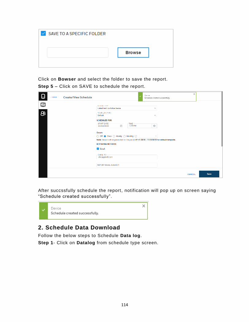
114
Click on Bowser and select the folder to save the report.
Step 5 – Click on SAVE to schedule the report.
After succssfully schedule the report , notif ication will pop up on screen saying
“Schedule created successfully”.
2. Schedule Data Download
Follow the below steps to Schedule Data log.
Step 1- Click on Datalog from schedule type screen.

115
Step 2– In below screen, enter the SCHEDULER NAME, Set Recurrence
interval and START DATE &Time, and Device Type by clicking on drop down.
Note- If user want to save the generated data log in specific folder, click on browse to select
the folder to save the data log.
Step 3- After selecting all the required input in the above screen, click
SCHEDULE to proceed.

116
After successfully create the schedule, notification will pop up on screen.
21 BW Solo Connectivity over Bluetooth to SSDC
21.1 Pre-requisites
Before you connect BW Solo to SSDC, verify the following prerequisite for
support of Bluetooth:
S.No Pre-requisites for BW Solo
BLE support
How to Check Action required if pre-
requisite not met
1 Bluetooth module
firmware in the BW Solo
device should be 1.02B or
higher
Can be seen in the BW Solo Device
Display
Update the BW Solo
Bluetooth FW using the
Safety Communicator
App on the Apple app
store/play store
2 Window’s 10 OS version
should be equal to 1809 or
higher
From the Computer, go to Command
prompt -> Settings -> Systems ->
About
Update the operating
system (to Win 10
V1809) or reach out to
your IT team to get it
upgraded.
3 System should have Intel
Bluetooth driver that to
equal or above 21.40.0.1.
(Software will attempt to
install this driver if not
present)
From the Computer, go to Command
prompt -> Device Manager ->
Bluetooth -> Intel Wireless
Bluetooth -> Properties -> Driver
This would be checked automatically
during SSDC installation and attempt
will made to upgrade. Due to
hardware limitations some systems
may not be upgradable.
Please reach out to your
IT team.
Note: This driver may not
be compatible to some
systems and in such
cases, Bluetooth will not
be supported on SSDC

117
21.2 Pairing BW Solo over Bluetooth in Windows
After verifying the above prerequisite (which is also automatically checked
during installation), follow the below steps to connect BW Solo to your
computer.
• Open Bluetooth connectivity settings on your system and turn ON the
Bluetooth, then click on “Add Bluetooth or other device”.
• On below screen, click on Bluetooth option to add Bluetooth devices.

118
• On below screen, you can see the available nearby Bluetooth devices to
pair.
• Click on available BW Solo device to pair.

119
• After you click on the BW Solo device, below screen will appear to enter
the PIN.
You can see the PIN number on BW Solo device and enter the correct
PIN, then click Connect to proceed.
• After successfully pairing the device, below screen will appear.

120
21.3 Working with BW Solo in Safety Suite
After pairing the BW Solo over bluetooth(section 21.2)
• Open Safety Suite Device Configurator on your system.
• Open “Device list view” screen on Device configurator and you can see the
paired BW Solo device on screen.
Note- Please click on refresh button to see the newly connected devices.
Note: BW Solo connectivity through Bluetooth would require ‘Allow Discovery on Bluetooth’
setting to be turned on. Go to settings and enable “Allow Discovery on Bluetooth” as shown
below.

121
Note- Bluetooth connectivity on Safety Suite needs-
• Windows 10 version 1809 or above.
• Intel Bluetooth Driver 21.60.0.4 or above.
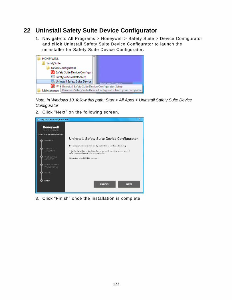
122
22 Uninstall Safety Suite Device Configurator
1. Navigate to All Programs > Honeywell > Safety Suite > Device Configurator
and click Uninstall Safety Suite Device Configurator to launch the
uninstaller for Safety Suite Device Configurator.
Note: In Windows 10, follow this path: Start > All Apps > Uninstall Safety Suite Device
Configurator
2. Click “Next” on the following screen.
3. Click “Finish” once the installation is complete.

123
22.1 Device Configurator Data Backup
To take Data backup, follow the instructions below.
Step 1- Go to windows run command (Win+R) and type SSMS (SQL Server
Management Studio) and click “OK”.
Note- Please download and install SSMS (available from Microsoft), if it is not already
installed on your computer.
Step 2- It will open SQL server management studio, Select server name as
‘SOTERAEXPRESS ’ and Authentication as ‘Windows Authentication ’, click on
“Connect”.

124
Step 3- After clicking on “Connect” you will see the below screen. Expand the
object with name SOTERAEXPRESS (SQL Server).
Step 4- Expand Database by clicking on ‘+ ’ symbol, you will be able to see the
SoteraExpress Database.

125
Step 5- Right click on the “SoteraExpress” and select as shown → Tasks →
Backup
Step 6- Please review the backup path, click “OK” to take the back up.
Step 7- Once complete, the following message will be shown.
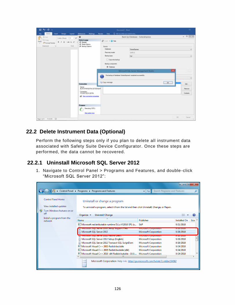
126
22.2 Delete Instrument Data (Optional)
Perform the following steps only if you plan to delete all instrument data
associated with Safety Suite Device Configurator. Once these steps are
performed, the data cannot be recovered.
22.2.1 Uninstall Microsoft SQL Server 2012
1. Navigate to Control Panel > Programs and Features, and double -click
“Microsoft SQL Server 2012”:

127
2. Click “Remove” to init iate the removal of Microsoft SQL Server 2012:

128
3. When the next screen is shown, click OK
4. Select Safety Suite Device Configurator from the drop-down menu, and click
“Next”

129
5. Click “Select All” followed by “Next”
6. When the new screen appears, click “Next”

130
7. Click on “Remove”
8. The removal progress is shown by a progress bar:
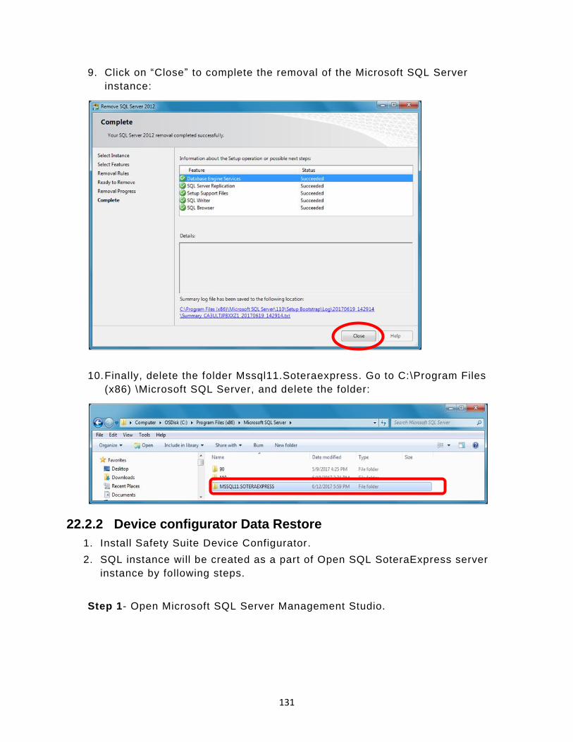
131
9. Click on “Close” to complete the removal of the Microsoft SQL Server
instance:
10. Finally, delete the folder Mssql11.Soteraexpress. Go to C:\Program Files
(x86) \Microsoft SQL Server, and delete the folder:
22.2.2 Device configurator Data Restore
1. Install Safety Suite Device Configurator.
2. SQL instance will be created as a part of Open SQL SoteraExpress server
instance by following steps.
Step 1- Open Microsoft SQL Server Management Studio.
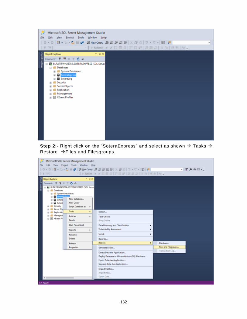
132
Step 2:- Right click on the “SoteraExpress” and select as shown → Tasks →
Restore →Files and Filesgroups.
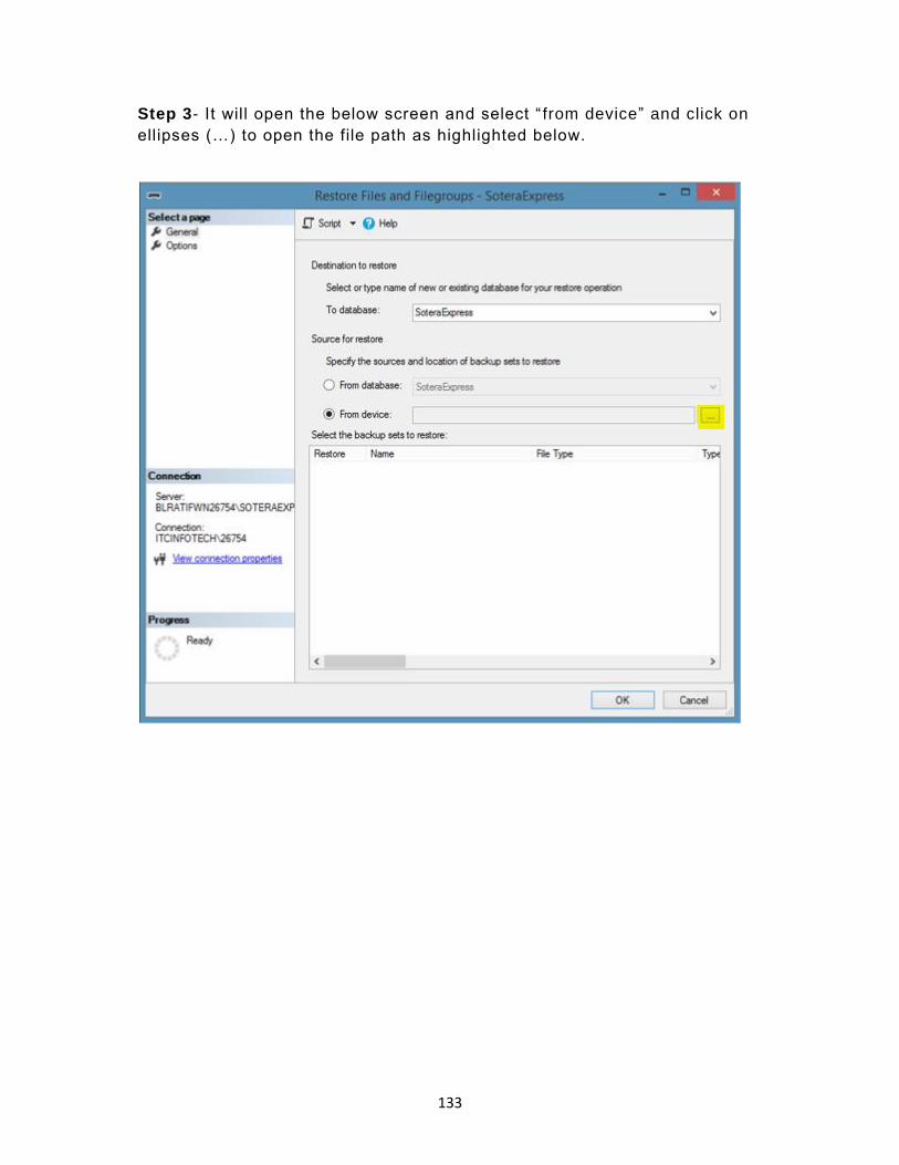
133
Step 3- It will open the below screen and select “ from device” and click on
ellipses (…) to open the file path as highlighted below.
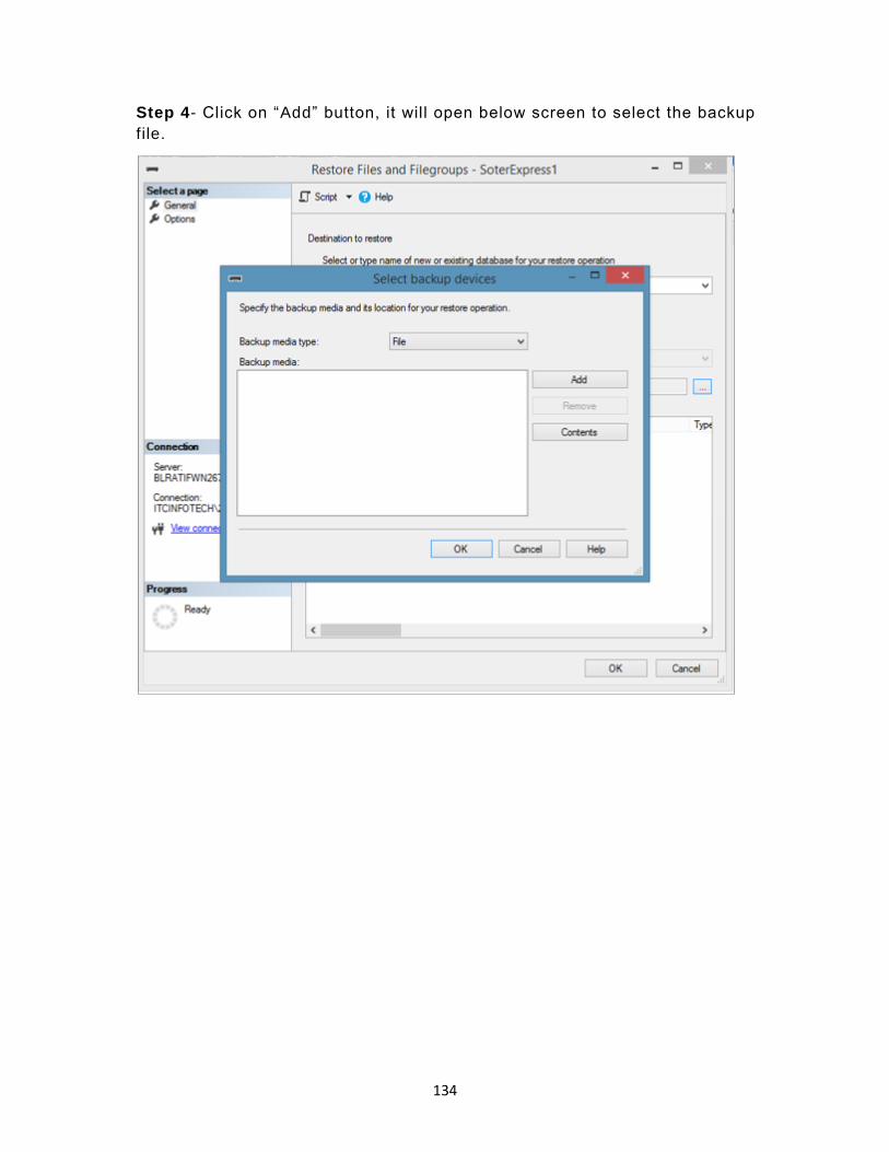
134
Step 4- Click on “Add” button, it will open below screen to select the backup
file.

135
Step 5: - Select the Backup as shown in below screen and click on “OK”.
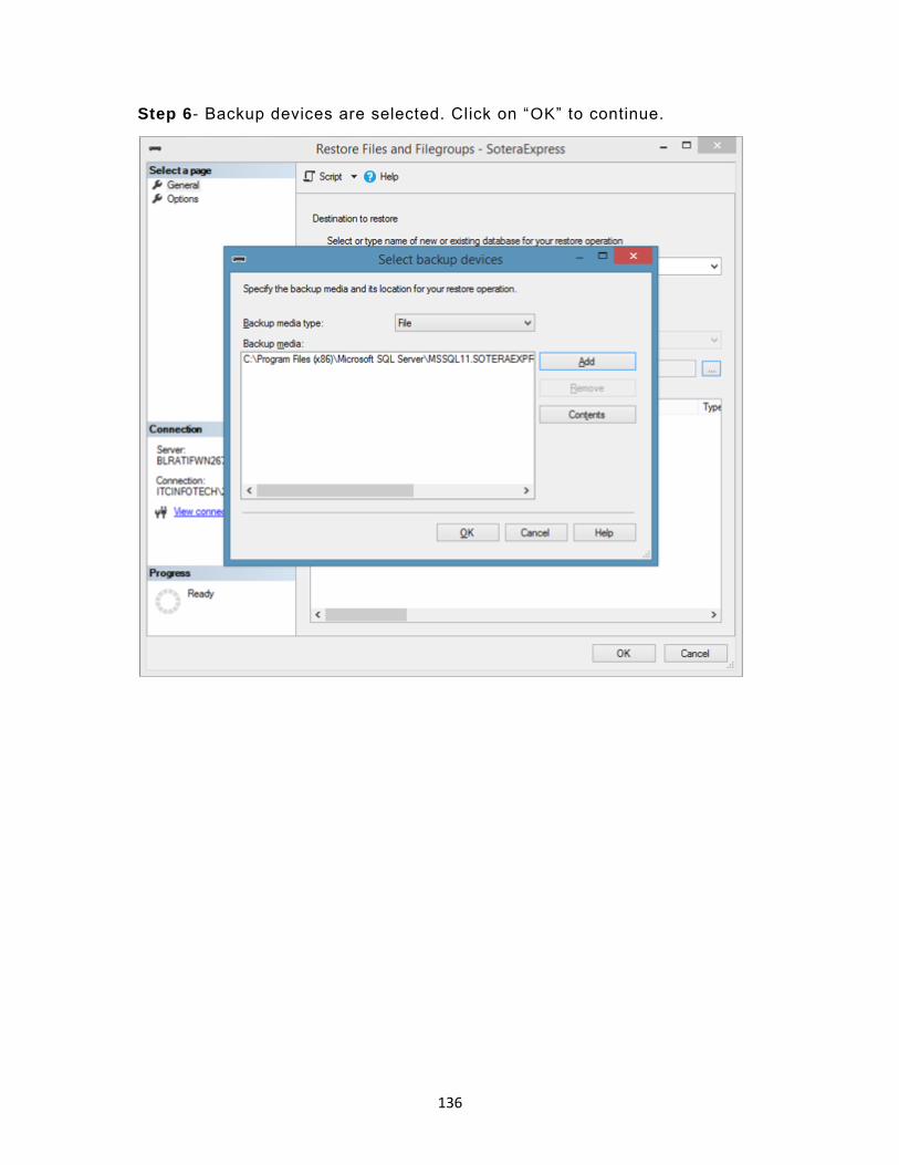
136
Step 6- Backup devices are selected. Click on “OK” to continue.
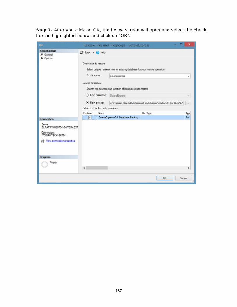
137
Step 7- After you click on OK, the below screen will open and select the check
box as highlighted below and click on “OK”.
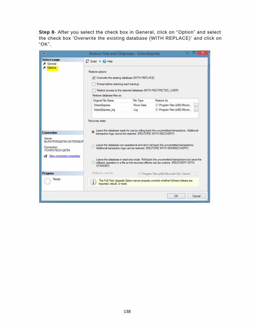
138
Step 8- After you select the check box in General, click on “Option” and select
the check box ‘Overwrite the existing database (WITH REPLACE) ’ and click on
“OK”.

139
Step 9- After you click on “OK”, the Database “SoteraExpress” will be restored
successfully.
23 Migrating ProRAE Studio Database to Safety Suite Device Configurator
You can migrate your existing ProRAE Studio database to Safety Suite Device
Configurator. This database contains historical data about RAE instruments.
IMPORTANT!
You must install Safety Suite Device Configurator before you perform the
transfer.
1. Identify ProRAE Studio database folders for migration and copy those folders
to the system where Safety Suite Device Configurator is installed.
2. Log into Safety Suite Device Configurator. The first time you do this, the
screen shown here will appear:

140
Note: This dialog is shown every time you log in until the migration is performed. If you do
not want to see this message, uncheck the option labeled “Remind me during next login”. At
the next login, under “Administrator”, select “Data Migration” from the menu and follow the
instructions in the dialog box:
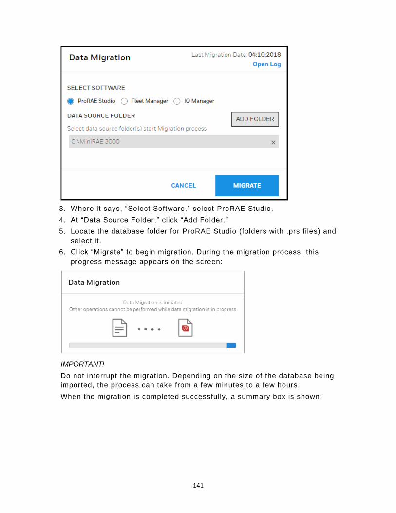
141
3. Where it says, “Select Software,” select ProRAE Studio.
4. At “Data Source Folder,” click “Add Folder.”
5. Locate the database folder for ProRAE Studio (folders with .prs files) and
select it.
6. Click “Migrate” to begin migration. During the migration process, this
progress message appears on the screen:
IMPORTANT!
Do not interrupt the migration. Depending on the size of the database being
imported, the process can take from a few minutes to a few hours.
When the migration is completed successfully, a summary box is shown:
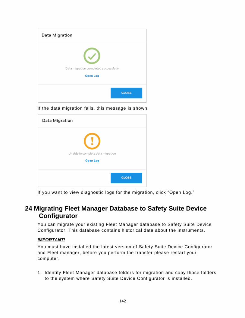
142
If the data migration fails, this message is shown:
If you want to view diagnostic logs for the migration, click “Open Log.”
24 Migrating Fleet Manager Database to Safety Suite Device Configurator
You can migrate your existing Fleet Manager database to Safety Suite Device
Configurator. This database contains historical data about the instruments.
IMPORTANT!
You must have installed the latest version of Safety Suite Device Configurator
and Fleet manager, before you perform the transfer please restart your
computer.
1. Identify Fleet Manager database folders for migration and copy those folders
to the system where Safety Suite Device Configurator is installed.

143
2. Log into Safety Suite Device Configurator. The first time you do this, the
screen shown here will appear:
Notes: This dialog is shown every time you log in until the migration is performed. If you do
not want to see this message, uncheck the option labeled “Remind me during next login.” At
the next login, under “Administrator,” select “Data Migration” from the menu and follow the
instructions in the dialog box:
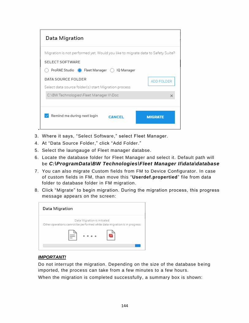
144
.
3. Where it says, “Select Software,” select Fleet Manager.
4. At “Data Source Folder ,” click “Add Folder.”
5. Select the laungauge of Fleet manager databse.
6. Locate the database folder for Fleet Manager and select it. Default path will
be C:\ProgramData\BW Technologies\Fleet Manager II\data\database
7. You can also migrate Custom fields from FM to Device Configurator. In case
of custom fields in FM, than move this “Userdef.propertied” file from data
folder to database folder in FM migration.
8. Click “Migrate” to begin migration. During the migration process, this progress
message appears on the screen:
IMPORTANT!
Do not interrupt the migration. Depending on the size of the database being
imported, the process can take from a few minutes to a few hours.
When the migration is completed successfully, a summary box is shown:

145
If the data migration fails, this message is shown:
If you want to view diagnostic logs for the migration, click “Open Log.”
Notes: After successful database migration, you are now able to view details for Gas Alert
Micro Clip and BW Clip instrument data in the database.
Safety Suite Device Configurator accepts the Fleet Manager Databases created
using Fleet Manager version v4.4.2. Any databases created using Fleet
Manager versions prior to this must first be upgraded using Fleet Manager.
25 Migrating IQ Manager Database to Safety Suite Device Configurator
You can migrate your existing IQ Manager database for ToxiPro devices to
Safety Suite Device Configurator. This database contains historical data about
the instruments.
IMPORTANT!

146
You must install Safety Suite Device Configurator before you perform the
transfer.
1. Log into Safety Suite Device Configurator. The first time you do this, the
screen shown here will appear:
Note: This dialog is shown every time you log in until the migration is performed. If you do
not want to see this message, uncheck the option labeled “Remind me during next login.” At
the next login, under “Administrator,” select “Data Migration” from the menu and follow the
instructions in the dialog box:
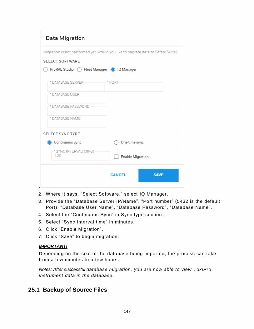
147
.
2. Where it says, “Select Software,” select IQ Manager.
3. Provide the “Database Server IP/Name”, “Port number” (5432 is the default
Port), “Database User Name”, “Database Password”, “Database Name”.
4. Select the “Continuous Sync” in Sync type section.
5. Select “Sync Interval time” in minutes.
6. Click “Enable Migration” .
7. Click “Save” to begin migration.
IMPORTANT!
Depending on the size of the database being imported, the process can take
from a few minutes to a few hours.
Notes: After successful database migration, you are now able to view ToxiPro
instrument data in the database.
25.1 Backup of Source Files
148
After completion of migration, the source files are available in this folder:
In case the Fleet Manager database includes data for instruments other than
BW Clip or Gas Alert Micro Clip, do not delete these files.19 Device
Configurator FAQs
26 Device Configurator FAQs
26.1 General Questions
➢ Do I have to purchase Honeywell Safety Suite Device Configurator before I can use it?
Honeywell Safety Suite Device Configurator is offered free of charge to all Honeywell
customers who purchase Honeywell Gas instruments.
➢ What are the minimum software and hardware requirements for Honeywell Safety Suite Device Configurator?
Hardware
o CPU, 1.0 GHz or higher
o Color monitor (1366x768 or higher resolution or higher, 16-bit color)
o 2 GB RAM
o 4 GB of free hard disk space
o USB port for instrument/dock connection
o LAN connection for network-connected docks
Software
o Microsoft Windows 7 SP1 (32 bit/64 bit) or Microsoft Windows 10 (64 bit)
o .Net Framework v4.6.1 or above
➢ Does Honeywell Safety Suite Device Configurator support data migration for Fleet Manager II, ProRAE Studio II and IQ Management Software Suite?
Honeywell Safety Suite Device Configurator supports data migration from Fleet Manager
II for all the supported instruments. In addition, it supports data migration for GasAlert
Extreme. Existing Fleet Manager II instances should be upgraded to the latest version
before initiating data migration. The software also supports data migration from ProRAE
Studio II for all supported RAE instruments. Data migration from IQ Management
Software Suite is Supported for ToxiPro.
➢ Can Honeywell Safety Suite Device Configurator manage both BW & RAE Systems instruments?
Yes, Honeywell Safety Suite Device Configurator is a single software solution designed
to support both BW & RAE Systems instruments and manage these devices though a
common interface and a central data repository which resides on the local system.

149
➢ What instrument connectivity options are currently supported by Honeywell Safety Suite Device Configurator?
Honeywell Safety Suite Device Configurator currently supports instrument connectivity
through IntelliDoX, MicroDock II and AutoRAE 2 for BW & RAE Systems instruments.
BW Instruments can connect directly through IR Dongle wherever applicable. RAE
instruments can also connect directly through the Travel Charger.
➢ What instruments are supported by Honeywell Safety Suite Device Configurator?
The following is a list of currently supported instruments.
IntelliDoX & MicroDock II
o BW Clip & BW Clip Real Time
o BW MicroClip XL & BW MicroClip X3 IntelliDoX
o BW Clip4
o BW Solo
o BW Ultra MicroDock II
o BW MaxXT II
o BW Quattro
o GasAlertMicro 5
IR Dongle
o BW MaxXT II
o BW MicroClip XL & BW MicroClip X3
o BW Quattro
o BW Ultra
AutoRAE 2 & Travel Charger
o MicroRAE
o MiniRAE 3000 & MiniRAE Lite
o MultiRAE Family (Benzene & Wing Tank model support in future releases)
o ppbRAE 3000
o QRAE 3
o ToxiRAE Pro Family
o Ultra 3000
Direct USB
o AreaRAE Plus & AreaRAE Pro
➢ Does Honeywell Safety Suite Device Configurator require administrative privileges on the windows operating system?
Yes, Honeywell Safety Suite Device Configurator does require administrative privileges
on the operating system.
➢ What Fleet Manager features are not supported by Honeywell Safety Suite Device Configurator?
150
Honeywell Safety Suite Device Configurator has streamlined the tasks performed by
Fleet Manager and greatly improves the overall user experience. However, it does not
support user- defined fields and custom reporting features of Fleet Manager.
➢ What should I do when Device Configurator does not respond?
Try to sign out and close the application. If does not work, kill the application using Task
Manager from the taskbar.
➢ Does Device Configurator work without Internet connection?
Device Configurator works without Internet connection. Automatic Firmware upgrade
does not work without Internet connection, user must select the firmware file to upgrade
the firmware.
➢ Where can I find Device Configurator user guide/ help document?
Help document is available the Device Inventory page. After login, you can see a
question icon on right corner of the top header, click on the icon and click on the “Help” to
see the help document.
26.2 Installation
➢ What all Windows version are supported for Device Configurator?
Device Configurator supports Windows 7(32bit,64bit) and Windows 10(64 bit).
➢ How to troubleshoot sql server issue during Device Configurator installation?
Please follow the steps for SQL server installation related issues.
o Go to user’s temp directory to get sql exe.
o This will look like C:\Users\(userid)\AppData\Local\Temp

151
o Click on file with 7zxxxxxx.tmp and it will open below screen
o Click on CD folder and will open below screen. Copy the path by clicking on the
folder at address bar.
o It will be looks like C:\Users\XXXX\AppData\Local\Temp\7zS55B0.tmp\cd

152
o Open command prompt as administrator and copy the sql path in cmd screen and
hit enter:
o cd C:\Users\xxxxxx\AppData\Local\Temp\7zS2286.tmp\cd
o After hitting enter button, cmd screen looks like below image.

153
o Copy the blow line and paste in cmd screen to uninstall SQL package completely.
o SQLEXPR_x86_ENU.exe /ACTION="unInstall"
/INDICATEPROGRESS="TRUE"/FEATURES=SQLENGINE,
REPLICATION,FULLTEXT,BIDS,CONN,IS,BC,SDK,BOL,SSMS,ADV_SSMS
o After copying the above line to cmd press enter button, this will uninstall package
completely.
o if any errors are coming continue with uninstallation and after that run the above
command again.
o To make sure all files removed, go to below path and delete all folders at -
C:\Program Files (x86)\Microsoft SQL Server

154
Both can be installed on same machine. While installing DM over DC, if you encounter
error that BW Device is already running then click on retry and continue with
installation.
➢ What all Honeywell Device Application should not be running when using Device Configurator?
Fleet Manager, ProRAE Studio, IQ Manager and ProRAE Guardian can be installed but
should not be running when using Device Configurator.
➢ What should I do when I see notification to reboot my machine repeatedly?
It means that SQL server is not installed properly and there is some issue in installing
SQL server. Please refer the question for SQL installation related issue.
➢ Device Configurator installed SQL server for its back-end database, is it possible to use a database on a shared server rather than a localized one on the PC?
The software is designed for local use on a PC. Each PC needs its own local copy.
➢ Device Configurator IIS does that mean the functions of the software are available via a webpage or does each PC that uses Fleet Manager need this software installing?
The software is designed for local use on a PC. Each PC needs its own local copy.
➢ The pre-requisites imply Device Configurator is a desktop app, but could this run on a server?
It should most likely be able to run on server. However, we have certified it only on
Windows 7 & Windows 10.
➢ How to deploy Device Configurator in a Firewalled environment? If they all use the installed SQL server database how would multiple installs work?
Each install uses its own SQL instance. You cannot share on SQL instance across
multiple installs.
➢ What happens if I do not create password immediately after the installation?
When user login next time, it ‘ll ask to create password.
26.3 Login
➢ I have installed Device Configurator but not able to login. What should I do?
A) Check the mentioned services are running, Open Services.msc in run window.
o SafetySuite.DCBWDeviceService
o SafetySuite.DCDatabaseService
o SafetySuite.DCMainService
o SafetySuite.DCRAEDeviceService

155
o SQL Server (SOTERAEXPRESS)
If not, please restart those services.
B) Check the files in the below location,
C:\Program Files (x86)\Microsoft SQL
Server\MSSQL11.SOTERAEXPRESS\MSSQL\DATA\
o SoteraExpress.mdf
o SoteraLog.mdf
are available.
➢ How can I reset Device Configurator application password?
If you have Administrator access and forgot your password, follow these steps -
o Click the “Windows” icon on the lower left side of your screen.
o Click “All apps.”
o Scroll down until you see “Honeywell.” Click the downward arrow to see “Unlock
Administrator Account.”
o When the “Windows Security” window appears, type in your Administrator
password for the PC.
o Click “OK.” An activation code is shown.
o Use this activation code to login to Safety Suite Device Configurator.
➢ How can I log on to the software if I have forgotten my password?
You can reset your password by clicking the “Forgot Password” link on the Login Screen.
Once you answer the security questions, you will be allowed to reset the password.
➢ How can I log on to the software if I have locked myself out of the default administrator account?
You can invoke the “Unlock Administrator Account” utility that is installed with the
software to unlock the default administrator account.
For security purposes, you will be prompted to provide the Windows administrator User
ID and password before you can unlock the Honeywell Safety Suite Device Configurator
administrator account.
Follow the steps to unlock the account –
o Click the “Windows” icon on the lower left side of your screen.
o Click “All apps.”
o Scroll down until you see “Honeywell.” Click the downward arrow to see “Unlock
Administrator Account.”
o When the “Windows Security” window appears, type in your Administrator
password for the PC.
o Click “OK.” An activation code is shown.
o Use this activation code to login to Safety Suite Device Configurator.
156
➢ How to check IIS is running on the machine?
Follow the steps to check if IIS is running-
o Click on Windows icon. Type “run” in search tab and press Enter.
o Type “inetmgr” and press enter.
o Check if “World Wide Web Publishing Service” is running.
o If not, Check answer to the question “How to enable IIS”.
➢ How to enable IIS?
Follow the instructions at - https://msdn.microsoft.com/en-
us/library/ms181052(v=vs.80).aspx to enable IIS.
➢ What is the default username and password for Honeywell Safety Suite Device Configurator?
The default Username is “administrator”. You are required to create a password for the
administrator account when you log into the application for the first time.
➢ I have entered correct username and password and clicked on login. I am still on login page.
Check if Device Configurator Database Service is running.
Steps to check and restart the service –
o Click on Windows icon.
o Type run and select run.
o In run windows, type services and press enter.
o Search SafetySuite.DCDataBaseServiceis and check if service status is running.
If not, do right click and select restart.
26.4 Device Inventory
➢ How do I see my instruments in the Device Inventory list?
For BW instruments connected through IntelliDoX, MicroDock II or IR Dongle, the
instrument data should be downloaded for the instruments to show up in the Device
Inventory. Make sure the filter option “Not Connected” is selected to view the instruments
in the Device Inventory List for which data has been downloaded. For RAE Systems
instruments connected through the AutoRAE 2, Travel Charger or Direct USB the
software should be able to communicate to the instruments to show up in the Device
Inventory list. In addition, instrument data should be downloaded to view the RAE
Systems instruments in the inventory after the instrument is disconnected from the
software. The filter option “Not Connected” should be selected to view RAE Systems
instruments in the Device Inventory List for which data has been downloaded but are
currently not connected to the software.
➢ What are the different options to connect Docking Stations to the software?
157
IntelliDoX can connect to the software over the network. MicroDock II can connect to the
software using direct USB connection. AutoRAE 2 can connect to the software either
over the network or using direct USB connection.
➢ I have connected the docking station over the network. However, I am not able to see the docking station in the software?
First, make sure the software is set up to scan for the RAE Systems and/or BW docking
stations by checking the appropriate box for “Allow Dock Discovery” under system
Settings. If the docking station is in a network path different than the software, the
software may not be able to see the docking station. In order for the software to see the
Docking Station, add the Docking Station manually to the software using “Add AutoRAE
Controller for manual detection” for AutoRAE 2 and “Add IntelliDoX for manual detection”
for IntelliDoX under the system Settings menu option using the IP Address of the Docking
Station.
➢ I have connected the docking station. However, it is not appearing online in the software.
The software periodically scans the USB ports and network to check the online status of
the docking station/instruments. However, the online status of the docking station might
not be reflected right away in the software. If you are unable to see the docking station
status online, you can click the Refresh button in the Device Inventory view to see the
online status of the docking station.
➢ Can I use the same package to update the firmware for the devices on Honeywell Safety Suite Device Configurator that I use to update the firmware with ProRAE Studio II and Fleet Manager II?
Honeywell Safety Suite Device Configurator uses digitally signed packages to update the
device firmware as a security mechanism to verify the integrity of firmware update
packages. As a result, it cannot use the same packages used by ProRAE Studio II and
Fleet Manager II. Firmware packages designated for Honeywell Safety Suite Device
Configurator should only be used to update device firmware through Honeywell Safety
Suite Device Configurator.
➢ What should be done if devices are connected and not appearing in device inventory list.
Sometimes the devices might take some time ( ~ 1-2 mins). If still the problem persists,
follow the below steps
o Check if the device is connected correctly.
o Disconnect and Reconnect the device.
o Now wait for 2-3 mins.
o If still the device doesn’t appear, use the manual refresh on the device inventory
page
o If still the problem persists, run the services.msc on the Command window and
restart all the services related to the Safety Suite.
o If not, kindly contact the tech support.

158
➢ How can I see only connected or only disconnected devices?
Use the filter provided on the Left-hand side of the screen and Select the “Connected” or
“Disconnected” to filter out the required devices list.
➢ What mode should the RAE device be to communicate to Device Configurator?
Make the RAE in “Communication Mode” to communicate with the Device Configurator.
Otherwise the RAE devices won’t communicate.
➢ Do I need driver to connect IR devices in Device Configurator?
Driver is required to connect IR device. When Device Configurator is installed first time, it
asks you to install IR driver while installation. Select yes to install the driver.
➢ Do I need driver to connect RAE device Configurator?
Driver is required to connect RAE device. When Device Configurator is installed first
time, it asks you to install AutoRAE driver while installation. Select yes to install the
driver.
➢ Do I need driver to connect IntelliDox device in Device Configurator?
Driver is not required to connect IntelliDox device.
➢ How do I check device connected previously?
From the LHS filter select the “Disconnected” devices to show all the devices which were
connected previously.
➢ How can I archive a device?
This is a feature whose implementation is still in progress. Expect it in future release of
the Application.
26.5 Device Data Download
➢ Does the software download existing data from the Docking Stations?
The software downloads all the historical data stored in the docking station. The
download time can vary depending on the size of the data, network bandwidth and
processing speed of the computer.
➢ I do not see the option to select a start and an end date for data downloaded in Honeywell Safety Suite Device Configurator.
The software utilizes a smart download manager to incrementally download the data to
optimize the download time. The software compares the existing downloaded data
against the latest logged data and downloads only the incremental data since the last
download.
➢ Does Honeywell Safety Suite Device Configurator support data download from IntelliDox USB connector?

159
The software supports data download via the USB connector on the IntelliDoX using a
USB storage device for BW Clip, BW Clip Real Time, BW MicroClip XL & BW MicroClip
X3, BW Clip4, BW Solo, BW Ultra.
➢ Can I download data of multiple devices at a time in Device Configurator?
Currently, you can only perform data download for one device at a time. You must wait
for the current operation to complete before performing another data download.
➢ How does data Download happen? Do I have initiate it or it happens when devices are discovered in Device Configurator?
Data download does not happen automatically, it must be initiated by user after
connecting devices to the application. RAE device, IntelliDox Device and IR should be
connected to Device Configurator to initiate data download. When you see the device in
Device Inventory, filter the device using serial no and click on “Actions” button. Click on
“Download Data” from the options.
➢ How long should I wait for Data Download to Complete?
If user downloads data first time, it depends on the amount of data available in the
device. If user downloads data of the same device again, it downloads the new data only.
➢ What happens if I disconnect device while data download is in progress?
Device must be connected till data download completes. If device is disconnected while
data download is in progress, complete data will not get downloaded and data down
failed notification will appear on the screen.
26.6 Device Configuration
➢ Why am I not able to save the Dock/Device Configuration?
To perform the Dock/Device Configuration, the Dock /Device needs to be connected to
the computer and appear online to the software.
➢ Can I download data and configure a device at the same time?
Currently, you can only perform one device action at a time. You must wait for the current
operation to complete before performing another action. Consequently, if you are
performing a data download, you must wait for the data download to complete before
performing a device configuration.
➢ For BW devices, unlike Fleet Manager, I do not see the Updatable option against each of the sensor parameters. Why?
Honeywell Safety Suite Device Configurator has a streamlined user interface to make it
easier to manage configuration parameters. As a result, a common Updatable option is
provided for all the configuration parameters, including the sensor settings, under the
Settings tab.
➢ For RAE Systems devices, can I update the Lot Number of the gas cylinder in the software?

160
You can navigate to the AutoRAE 2 details and edit the gas inlet configuration details for
the attached gas cylinder in order to update the Lot Number of the gas cylinder.
➢ For RAE Systems devices, can I update the Sensor Serial No. after installing a new sensor?
Yes, you can update the Sensor Serial No. of RAE devices after installing a new sensor
for the instruments that support this option under the Sensors tab for the corresponding
instruments if they are currently online and connected to the software.
➢ Does Honeywell Safety Suite Device Configurator support instrument configuration use IntelliDox USB connector?
The software supports instrument configuration via the USB connector on the IntelliDoX
using a USB storage device for BW Clip, BW Clip Real Time, BW MicroClip XL & BW
MicroClip X3, BW Clip4, BW Solo, BW Ultra.
➢ I am unable to save configuration in MicroDock. What should I do?
PC where MicroDock is connected must have write access to USB connected devices.
Verify if you have the access. MicroDock creates a temporary drive on the PC when
connected and read and write operation happens on the same drive.
26.7 Device History
➢ What information is presented in Device History?
Device History provides a comprehensive view of all the data related to the lifecycle of
the selected instrument. This includes test data for calibration and bump tests. This also
includes the instrument event data, along with the corresponding data logs.
➢ Are all device-related data logs, event logs and test data logs shown in the Device History?
All information related to device data logs, event logs and test logs is shown in the
Device History, with the exception of IntelliDoX & MicroDock II data logs and BW
instrument test logs for bump and calibration operations performed outside of the
IntelliDoX & MicroDock II.
➢ Why can’t I see the Device History?
Make sure that you have downloaded the data from the docking station corresponding to
the selected instrument before viewing the Device History. Once the data has been
downloaded, you can view the history for the selected device.
➢ Can I export the data log corresponding to the events captured by the instrument?
Yes, you can export the instrument data log in csv (comma-separated value) format,
which can be opened in Microsoft Excel for further analysis.
➢ Can I delete the data log for an instrument once it has been imported into the software?

161
We do not allow data logs to be deleted once they have been downloaded to the
software.
➢ What is the maximum date range in I can select in calendar to see Device History?
The maximum date range that can be selected in calendar is 1 year, at any given point of
time. However, the user can select any date range of maximum one year up to current
date. For ex: User can select the date range of 1-1-2013 to 31-12-2013 in Calendar.
26.8 User Management
➢ What are the different roles I can assign to a user?
You can assign one or more of the following roles to a user:
Administrator – A user with the administrator role has access to all the features and
functionality within the system.
Advanced User – A user with the advanced role can perform all the device operations.
However, the user does not have access to user management.
Standard User – A user with the standard role can perform all device operations except
device configuration and firmware updates.
Worker – A user with the worker role has no access to the software. However, the user
can be assigned/unassigned instruments.
➢ I want to assign an instrument to an individual. However, I do not want to provide the individual with access the software.
You can assign a user the “Worker” role if you want to just assign instruments to the
user.
➢ What is the purpose of deactivating a user account?
If you want to suspend user access to the system, you can do that by deactivating the
user account.
➢ Can I change the username of the admin user in Device Configurator?
No, username of the admin user cannot be updated.
➢ How do I update the admin user profile?
Follow the steps to update the profile -
o Login to the application. Click on the User icon available on the right side of the
top header.
o Select “Edit Profile”.
o Update the user profile fields which are updatable.
o To save the updated profile, click Save button.
➢ How do I update user profile of the user’s other than the admin user?
Follow the steps to update the profile -

162
o Login to the application. Click on the User icon available on the left-hand side bar
on the Inventory page.
o Filter the user with username or name of the user.
o Click on “Actions” button of the username. Select “User details”.
o Update the user profile fields which are updatable.
o To save the updated profile, click Save button.
26.9 Data Migration
➢ Can BW device data be migrated when both FM and Device Configurator Running?
No, we cannot migrate the data when FM and Device Configurator are running. We can
migrate data to Device configurator after closing FM.
➢ Can I migrate IntelliDox and MicroDock data log in Device Configurator?
No, we cannot Migrate IntelliDox and MicroDock data log in Device configurator. Data log
of the devices docked in IntelliDox and MicroDock can only be migrated.
➢ Does a device which has no data get migrated?
We cannot migrate a device which does not have any data.
➢ Why do I see the difference in date and time of the data logs in FM and Device Configurator?
FM shows the data in UTC format, in Device Configurator the data is shown in the local
time zone of the computer where it is installed.
➢ How can I migrate custom fields from FM to Device Configurator?
Yes, we can migrate custom fields from FM to Device Configurator. In case of custom
fields in FM then move this “Userdef.propertied” file from data folder to database folder in
FM migration.
➢ How can I migrate data log, event log and results from PRS to Device Configurator?
Launch the Device configurator and login as Administrator.
o Navigate to “Data migration” dropdown option in the User tab\option in top right
menu of the application.
o Select the software "ProRae Studio”.
o In the “Data Source Folder”: Click “ADD FOLDER”
o Now select the path of the PRS files folder. (Note: keep the files in the path other
than Desktop)
o Then “MIGRATE” Button will be enabled.
o Click “MIGRATE”
o The Migration process starts and the user will be notified after the migration is
completed.
163
➢ How can I migrate data log, event log and results from FM to Device Configurator?
Launch the Device configurator and login as Administrator.
o Navigate to “Data migration” dropdown option in the User tab\option in top right
menu of the application.
o Select the software "Fleet Manager”.
o In the “Data Source Folder”: Click “ADD FOLDER”
o Now select the path of the Root folder where all the FM Device files are placed.
(Note: keep the files in the path other than Desktop)
o Then “MIGRATE” Button will be enabled.
o Click “MIGRATE”
o The Migration process starts and the user will be notified after the migration is
completed.
➢ How can I migrate data log, event log and results from IQ Manager to Device Configurator?
Launch the Device configurator and login as Administrator.
o Navigate to “Data migration” dropdown option in the User tab\option in top right
menu of the application.
o Select the software "IQ Manager”.
o In the “Data Source Folder”: Click “ ADD FOLDER”
o Now select the path of the IQ Manager DB Server details.
o Then “MIGRATE” Button will be enabled.
o Click “MIGRATE”
o The Migration process starts and the user will be notified after the migration is
completed.
➢ Can I do selective data migration of users only, data log only, custom field only?
There is no option to select a type of data for migration. Complete data is migrated when
migration is done.
➢ FM is installed but I do not see FM data folder, what should I do to access the data folder?
Data folder is hidden. To see the folder, follow the steps -
o Navigate to computer drive “C:\ “and set “show hidden files and folders” in view.
o Then Programdata folder will be visible, the files can be seen in below path.
o “C:\ProgramData\BW Technologies\Fleet Manager II\data\database” folder
➢ Where should I keep data migration files for successful migration?
The Data files should be placed in a folder other than the Desktop or the path where the
Folder has the permissions to get retrieved by Device Configurator.
➢ How long should I wait for Data Migration to complete?

164
Depends on the Data present in the files. (Max 4 hours.)
➢ What files are supported for Data Migration?
Files supported for Data Migration are
o Properties, .Script, .Data, .fmdl extension files are supported for FM.
o .prs for Proraestudio.
o IQ manager connects to DB directly.
➢ What different type of data can be migrated from FM to Device Configurator?
We can migrate Data log, Test log, Event log, Users, Custom fields.
➢ What different type of data can be migrated from PRS to Device Configurator?
We can migrate Data log, Test log, Event log fields.
➢ What different type of data can be migrated from IQ Manager to Device Configurator?
We can migrate Data log, Test log, Event log.
➢ I am not able to select the folder for data migration. What should I do?
Check the folder has permissions to be selectable, once permissions are given the folder
will be selectable.
➢ Can I migrate data from Device Configurator to Device Manager, FM, PRS, IQ Manager?
No, we cannot migrate.
➢ Notes for Data Migration –
o In case of custom fields in FM then move this “Userdef.propertied” file from data
folder to database folder in FM migration.
o Close FM before initiating the DB migration.
o Recommended that if there are any data log file then archive then migrate.
o Do not perform any other operations like data download while data migration is in
progress.
o Large file migration – need to check at service side about segregation.
o Default Intellidox Date/Time UTC, same will be shown when downloaded in FM.
Hence data shown in FM assumed as UTC and get converted to locale date/time
in DC/DM.
o FM: Intellidox and Microdock data also appears against the respective devices.
o Devices having data and Users assigned with devices alone will get migrated.
o IQ Manager data migration – First time migration does the full migration,
subsequent migration do only delta data based on set interval.
26.10 Firmware

165
➢ What all firmware versions are supported in RAE?
Device Firmware Version supported in Safety Suite.
Product Name Version Name
AreaRAE Pro v1.08
AutoRAE 2 Controller v1.38
MicroRAE Cradle v1.38
MultiRAE (Pumped) Cradle v1.38
MultiRAE Cradle v1.38
QRAE 3 Cradle v1.38
ToxiRAE Pro Cradle v1.38
MicroRAE v1.12
MultiRAE v1.50
MultiRAE Lite v1.50
MultiRAE Pro v1.50
ppbRAE 3000 v2.20.A
MiniRAE 3000 v2.20.A
MiniRAE Lite v2.20.A
UltraRAE 3000 v2.20.A
ToxiRAE Pro CO2 v1.84
ToxiRAE Pro v1.84
ToxiRAE Pro LEL v1.84
ToxiRAE Pro PID v1.84
QRAE 3 v2.16A
➢ What all firmware versions are supported in BW?
Device Firmware Version supported in Safety Suite.
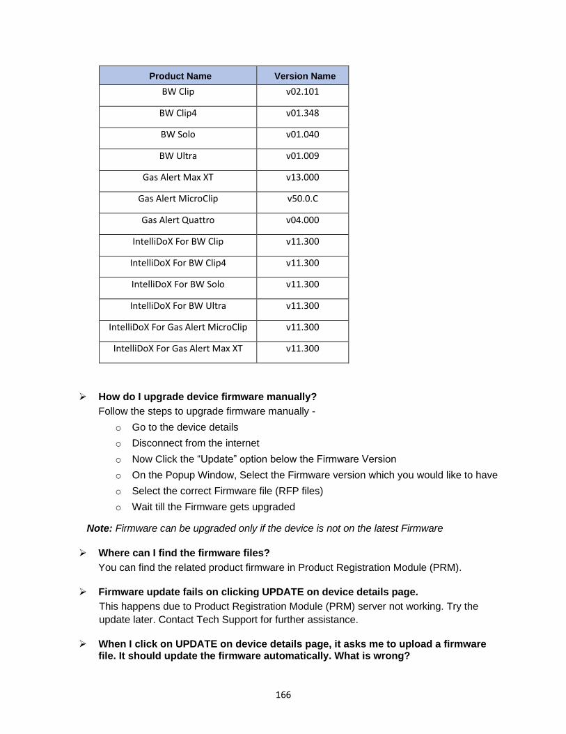
166
Product Name Version Name
BW Clip v02.101
BW Clip4 v01.348
BW Solo v01.040
BW Ultra v01.009
Gas Alert Max XT v13.000
Gas Alert MicroClip v50.0.C
Gas Alert Quattro v04.000
IntelliDoX For BW Clip v11.300
IntelliDoX For BW Clip4 v11.300
IntelliDoX For BW Solo v11.300
IntelliDoX For BW Ultra v11.300
IntelliDoX For Gas Alert MicroClip v11.300
IntelliDoX For Gas Alert Max XT v11.300
➢ How do I upgrade device firmware manually?
Follow the steps to upgrade firmware manually -
o Go to the device details
o Disconnect from the internet
o Now Click the “Update” option below the Firmware Version
o On the Popup Window, Select the Firmware version which you would like to have
o Select the correct Firmware file (RFP files)
o Wait till the Firmware gets upgraded
Note: Firmware can be upgraded only if the device is not on the latest Firmware
➢ Where can I find the firmware files?
You can find the related product firmware in Product Registration Module (PRM).
➢ Firmware update fails on clicking UPDATE on device details page.
This happens due to Product Registration Module (PRM) server not working. Try the
update later. Contact Tech Support for further assistance.
➢ When I click on UPDATE on device details page, it asks me to upload a firmware file. It should update the firmware automatically. What is wrong?

167
This happens due to Product Registration Module (PRM) server not working. Try the
update later or update the firmware with the supported firmware file. Contact Tech
Support for further assistance.
➢ Device firmware version is latest, and I see “UPDATE” button enabled on device details page. Do I need to upgrade the firmware?
This happens due to Product Registration Module (PRM) server not working. Contact
Tech Support for further assistance.
26.11 Passcode
➢ What is the purpose of Network Passcode, Menu Passcode and IntelliDox Web passcode?
o Network Passcode: To Secure the IntelliDoX data from unauthorized access in
the Safety Suite.
o Menu Passcode: To Secure the IntelliDoX Menu from unauthorized access in
the IntelliDoX.
o IntelliDoX Web Passcode: To View and Modify the Network Parameters and
IntelliDox Information of IntelliDoX.
➢ When passcode is required for IntelliDox?
Passcode is required to access the IntelliDoX for version 9.0 or above.
➢ How does Passcode work when IntelliDox firmware is upgraded?
Passcode would be retained even if the IntelliDoX firmware is upgraded.
➢ Why am I not able to perform “Device Details” and “Data Download” options in the instrument list view for some of the IntelliDox?
To perform “Device Details” and “Data Download” in the instrument list view, you should
provide the network passcode to IntelliDoX for version 9.0 or above.
➢ Where can I view the network Passcode in Device Configurator?
You cannot view the Passcode in Device Configurator.
➢ Can I configure network Passcode through Device Configurator?
Yes, you can configure the Network Passcode.
o After the IntelliDoX is visible as Connected in Device Discovery Page
o Go to the Actions drop-down and Select the “Set Passcode”.
o Provide the same passcode as the one in IntelliDoX and click Continue.
o The Message will appear, whether the provided passcode is correct, or not.
o After this the operation remains the same as before.
26.12 Language Support

168
➢ Does Device Configurator application text appear in languages other than English?
No, Currently Device Configurator application will display text only in English irrespective
of the base OS Language or Locale/ Chrome browser settings being set.
➢ Can I give data inputs in language other than English?
No, currently data inputs can be given only as per US English language format.
Ex: Decimal notation will be “.” So sensor values will be in the form “12.7”.
➢ If I my PC OS is not English, Can I use Device Configurator?
Yes, even if PC OS is not in English, Device Configurator application can be launched
and used. The language inputs and text will still be in English though.
➢ What languages are currently supported by Honeywell Safety Suite Device Configurator?
Currently only English language is being supported by Safety Suite Device Configurator.
26.13 Device Registration
➢ How do I register a device in Device Configurator?
Follow the steps to register a device:
o Login to the Device Configurator.
o Inventory page header has a device icon. Click on the icon.
o The devices connected will appear in the registration window.
o Click on the register button to register the devices.
Note: To register devices automatically, select checkbox “Register new devices
automatically”.
26.14 Event Report
➢ How do I generate event report?
Follow the below steps:
o Go to the Reporting Tab on the LHS on the Device Inventory page
o Select the “Event Log” in the Report type
o Select the date range for which the report needs to be generated
o Then select the Device Serial number from the drop-down and click Generate.
o A pdf file of the report will be generated in the Notification.
➢ What is the maximum date range I can select to generate report?
The maximum date range that can be selected in calendar is 1 year, at any given point of
time. However, the user can select any date range of maximum one year up to current
date.
For ex: User can select the date range of 1-1-2013 to 31-12-2013 in Calendar

For more information www.honeywellanalytics.com www.raesystems.com
Europe, Middle East, Africa Life Safety Distribution GmbH Tel: 00800 333 222 44 (Free phone number) Tel: +41 44 943 4380 (Alternative number) Fax: 00800 333 222 55 Middle East Tel: +971 4 450 5800 (Fixed Gas Detection) Middle East Tel: +971 4 450 5852 (Portable Gas Detection) [email protected]
Americas Honeywell Analytics Distribution Inc. Tel: +1 888 749 8878 Fax: +1 817 274 8321 [email protected] Honeywell RAE Systems Phone: 408 952 8200 Toll Free: 1 888 723 4800 Fax: 408 952 8480
Asia Pacific Honeywell Analytics Asia Pacific Tel: +82 (0) 2 6909 0300 Fax: +82 (0) 2 2025 0328 India Tel: +91 124 4752700 [email protected]
Technical Support [email protected] 1-833-556-3515