safety requirements for the use, care and protection of ... scope and definitions.pdf · 1 american...
TRANSCRIPT

1
AMERICAN NATIONAL STANDARD ANSI B7.1-2010
American National Standard
Safety Requirements for the Use, Care and Protection of Abrasive Wheels
1 Scope and definitions
1.1 Scope
This safety standard sets forth requirements for the safe use, care and protection of abrasive wheels and the machines for which they are designed. Included in this standard are the requirements for safety guards, flanges, chucks and proper storage, handling and mounting techniques.
exclusions from this standard are natural sand-stone, pulpstone and coated abrasive products. This standard also does not apply to machines using loose abrasives.
1.2 Definitions
1.2.1 abrasive wheel/grinding wheel:* An abrasive wheel is a grinding tool consisting of abrasive grains held together by organic or in-organic bonds. Diamond and reinforced wheels are included under this definition.
1.2.2 actuating controls: Operator controls used to initiate machine motion (see trip).
1.2.3 arbor: A shaft, mandrel, spindle or axle.
1.2.4 barrier: A physical boundary to a haz-ard.
1.2.5 base [frame] [head] [housing] [stand]: The basic and primary structure of the ma-chine.
1.2.6 blade tensioning: Steel centered super abrasive cut-off wheels are “tensioned” when manufactured to neutralize the residual stresses within the steel center so that the wheels will run true at the speed for which they are in-tended.
* Definition taken from ANSI B11.9.
E 1.2.1 abrasive wheel/grinding wheel
Illustration 1 – Examples of the various types of abrasive wheels included in this standard
E 1.2.6 blade tensioning
various residual stresses are imparted to the wheel’s steel center during manufacture of steel, during manufacture of the wheel center and during manufacture of the wheel itself. These stresses tend not to be evenly distributed throughout the core. Therefore, in operation, the wheel tends to not run true, i.e. it tends to wobble or flutter.
explanatory Information(NOT PART OF ANSI STANDARD)
2
ANSI B7.1-2010
1.2.7 blotters: Compressible discs or wash-ers usually of blotting paper stock, plastic, cardboard or gasket material, used between the wheel and flanges when mounting. See section 5.6.
1.2.8 bushing, reducing: See reducing bush-ings.
1.2.9 center: A part that supports a workpiece on its axis of rotation.
1.2.10 chuck: A fixture designed to hold abra-sive segments or certain types of abrasive wheels and is mounted on a machine spindle or machine face plate.
1.2.11 coated abrasive tool:* A coated abrasive tool consists of a layer of abrasive particles firmly attached to a paper, cloth or fiber back-ing, or other flexible bonding material by means of a bonding agent.
1.2.12 collet (collet chuck): A holder for grip-ping a workpiece or tool.
1.2.13 component: A constituent part.
1.2.14 configuration: A functional arrange-ment.
1.2.15 control, operator: An operator activated push button, switch, lever, hand wheel or other device that initiates, cycles, controls or stops motion of the machine.
1.2.16 control system: Sensors, manual input and mode selection elements, interlocking and decision-making circuitry and output ele-ments to the machine operating devices and mechanisms.
1.2.17 coolant: A fluid that is directed on the material or a workpiece and tool to dissipate heat and to provide lubrication for the cutting process (machining process) (material removal process).
1.2.18 cover, movable: An attachment that shields the opening of the work station, but can be moved to provide access.
1.2.19 design: Develop and plan machine construction to meet the intended purpose and function.
* Definition taken from ANSI B11.9.

3
ANSI B7.1-2010
1.2.20 device: A piece of equipment or a mechanism designed to serve a special pur-pose or perform a special function. (See device, safety.)
1.2.21 device, auxiliary: A device that by itself does not safeguard hazards but is required to ensure the proper operation of the safeguarding (guards, safety devices or methods).
1.2.22 device, safety: A means that detects or prevents inadvertent access to a hazard (see safeguarding).
1.2.23 discrete parts or assemblies: Separate or distinct units or elements that are consid-ered output or work in progress of an industrial machine or manufacturing system.
1.2.24 dressing:* Dressing is the process of removing bond material from around the cut-ting grains or diamonds in order to expose new, sharp cutting edges and to provide chip clearance for the material removal process. (See truing.)
1.2.25 enclosure, additional: Additional en-closure is protection which isolates the opera-tion from people in the surrounding area. (See splash shield.)
1.2.26 exhaust zone: The effective area of the ventilation system used for control of dust and fumes.
1.2.27 flanges: Flanges are collars, discs or plates between or against which wheels are mounted and are referred to as adaptor, sleeve, straight relieved or straight unrelieved types.
1.2.28 frame: See base.
1.2.29 grind cycle: The period of time, either continuous or intermittent, during which the grinding tool is engaged to remove material from the workpiece.
1.2.30 grinding machine:* A grinding machine, designed primarily for metal removal, presents a grinding tool against a workpiece, producing a change in shape, size, and surface finish. It may also be used for grinding material other than metals such as glass, ceramics, plastics, and rubber.
* Definition taken from ANSI B11.9.

4
ANSI B7.1-2010
1.2.31 grinding surface or face: The grinding surface or face is the surface of the abrasive wheel upon which grinding is properly per-formed.
1.2.32 grinding tool: See section 1.2.1.
1.2.33 guard:* A barrier that prevents entry into the point of operation or other hazard area.
1.2.34 guard, adjustable barrier: A guard with provisions for adjustment to accommodate vari-ous jobs or tooling setups.
1.2.35 guard, fixed barrier: A guard affixed to the frame, bolster or other surface in such a manner so as to enclose all or part of the point of operation or other hazard area.
1.2.36 guard, interlocked: A fixed or movable barrier or section of a barrier interlocked with the machine control system to (1) prevent normal machine actuation when the barrier is open or (2) prevent opening of the barrier or section of the barrier while the machine is in motion.
1.2.37 guard, wheel safety: See safety guard, wheel.
1.2.38 hazard: A condition or set of circum-stances that can cause physical harm to ex-posed personnel.
1.2.39 hazardous motion: Motion of equipment or release of energy that poses a hazard.
1.2.40 head: See base.
1.2.41 headstock (horizontal lathe or grind-er): The machine component that houses one or more spindles on which a chuck, grinding wheel, table, or work holding device is mounted.
1.2.42 honing tool: A honing tool contains one or more abrasive tools, mounted in a holder, that has a provision for moving the abrasive cutting tools against a workpiece.
1.2.43 housing: See base.
* Definition taken from ANSI B11.9.
E 1.2.31 grinding surface or face
GRINDINGSURFACE
TD
H
Type 1 straight wheel
T
W
E
J
DK
H
GRINDINGSURFACE
Type 11 flaring-cup wheel
Illustration 2 – Grinding surfaces are as indicated

5
ANSI B7.1-2010
1.2.44 inorganic bonded wheels: Inorganic wheels are bonded by means of inorganic material such as clay, glass, porcelain sodium silicate, magnesium oxychloride, or metal. Wheels bonded with clay, glass, porcelain or related ceramic materials are characterized as “vitrified bonded wheels.”
1.2.45 installer:* An installer is an individual, partnership or corporation that is responsible for the placement and preparation for use of a grinding machine.
1.2.46 integrator: A supplier that designs, pro-vides, manufactures or assembles a machine, its associated machines or equipment, the safeguarding, control interfaces, and intercon-nections of the control system into a machine production system. (See supplier.)
1.2.47 interlock: A means or device that al-lows a hazardous condition to exist only when a predetermined set of conditions is met.
1.2.48 machine cycle:* A machine cycle is the period of time that encompasses the grind cycle and all other machine functions required in the operation before and after the grind cycle. loading and unloading of the part either manually or automatically may be included in the cycle.
1.2.49 machine supplier: (a) Any individual, person, partnership, corporation or other form of enterprise engaged in the development and/or manufacture of any type of machine which uses an abrasive wheel. (b) One who converts, changes or otherwise alters the original design of such machines.
1.2.50 maintenance: To keep in an existing state (of repair).
1.2.51 manufacturer:* (a) machine manufactur-er — Any individual, partnership, corporation, or other form of enterprise which is engaged in the development, manufacture, alteration, repair, or rebuilding of any type of grinding machine that falls within the scope of this standard. (b) wheel manufacturer — Any individual, partnership, corporation or other form of enterprise which manufacturers any kind of abrasive wheel or which alters or repairs, other than normal truing or dressing, an abrasive wheel.
* Definition taken from ANSI B11.9.

6
ANSI B7.1-2010
1.2.52 mechanism: An arrangement of compo-nents to accomplish a given function.
1.2.53 modification (modify): To make a change to the machine/abrasive wheel or sys-tem that changes its original purpose, function, intended use, capacity, operation or safeguard-ing requirements.
NOTE: For the purposes of this standard, modifi-cation includes any effects that the change(s) has on other portions of the machine/abrasive wheel or system, including safeguarding, not directly a part of the modification.
1.2.54 modifier: Anyone that changes the original purpose, intended use, function or capacity of the machine or system by design or construction. (See supplier.)
1.2.55 mount down: Wheels marked with the “Mount Down” designation, shall be mounted onto the horizontally positioned grinding spindle with the “Mount Down” mark pointing down.
1.2.56 mount up: Wheels marked with the “Mount Up” designation shall be mounted onto the horizontally positioned grinding spindle with the “Mount Up” mark pointing up.
1.2.57 normal operation: The operating condi-tion where the manufacturing system, cell or machines and related equipment perform their intended tasks automatically or unattended with infrequent manual intervention.
1.2.58 nose, spindle: The portion of the spindle on which are mounted either internal or external workholding devices such as chucks.
1.2.59 operator:* An individual who performs production work and who controls machines.
1.2.60 organic bonded wheels: Wheels that are bonded by means of organic material such as resin, rubber, shellac, or other similar bond-ing agents.
1.2.61 owner: See user.
* Definition taken from ANSI B11.9.
E 1.2.55 mount down
By mounting the wheel as indicated it will be located in the same position as used while be-ing manufactured. This position will ensure best concentric running accuracy and balance. This mark is used on grinding wheels that are not normally dressed before use. Consult individual wheel manufacture for complete explanation.
E 1.2.56 mount up
By mounting the wheel as indicated it will be located in the same position as used while being manufactured. This position will ensure best concentric running accuracy and balance. This mark is used on grinding wheels normally larger than 14″ in diameter that are mounted between flanges on horizontal spindles. Con-sult individual wheel manufacture for complete explanation.

7
ANSI B7.1-2010
1.2.62 peripheral member: A peripheral mem-ber is the front portion of a self closing guard on a floorstand grinder. See illustration 51, page 60.
1.2.63 personnel, instructed: Personnel who are instructed in the performance of a specific task(s).
1.2.64 personnel, skilled: Personnel with technical knowledge or sufficient experience to recognize potential hazards involved in the performance of their assigned task(s).
1.2.65 pin, drive: A dowel, secured to the fixed or inner flange, of sufficient length to extend through a corresponding clearance hole in the abrasive and/or diamond saw blade and into the outer flange.
1.2.66 point of operation:* A point of opera-tion is the area of the grinding machine where material is positioned and work performed by the grinding tool.
1.2.67 rebuilder (reconstructor): Any indi-vidual, person, partnership, corporation or other form of enterprise which restores the machine or system to its original design, purpose, capacity and function. (See manufacturer.)
1.2.68 rebuilding (reconstruction): Restoring or rebuilding the machine or system to its origi-nal design, purpose, capacity and function.
NOTE: Rebuilding (reconstruction) involves the restoration or replacement of major components of the machine or system and is not considered a maintenance or repair activity.
1.2.69 reducing bushings: Reducing bush-ings are inserts or devices used to reduce the hole size in a grinding wheel so that it can be mounted on a smaller diameter spindle.
* Definition taken from ANSI B11.9.
E 1.2.69 reducing bushings
Illustration 3 – One type of reducing bushing com-monly used to reduce an abrasive wheel
hole size

9
ANSI B7.1-2010
1.2.78 shall and should: The word “Shall” where used is to be understood as manda-tory, “Should” as advisory and “May” denotes a permissible course of action within the limits of the standard.
1.2.79 shield:* A barrier used to keep chips or coolant within the confines of the machine; a barrier used to reduce the potential of tooling parts or workpieces from being ejected from the machine.
1.2.80 splash shield: A barrier used to keep chips or coolant within the confines of the machine.
1.2.81 spindle: A power-driven shaft-like mem-ber mounted on bearings.
1.2.82 stand: See base.
1.2.83 station, work: The area on the ma-chine where grinding, cutting-off or honing is performed.
1.2.84 steel rings: Steel rings are circular bands of steel usually of round cross section which may be incorporated into abrasive wheels by the manufacturer.
1.2.85 supervised: A means or method where the user can exercise permissive control over the operation of the machine.
1.2.86 supervisor: An individual who is autho-rized by and acts on behalf of the employer and directs activities of other employees.
1.2.87 supplier: An individual, corporation, partnership or other legal entity or form of business. For the purposes of this standard, a supplier provides, or makes available for use, all or part of the machine, or wheels. A supplier can be any one of the following entities such as defined under manufacturer, reconstructor, modifier, installer and integrator.
* Definition taken from ANSI B11.9.
E 1.2.78 shall and should
The sketches and photographs used in this publication are classified as “Figures” or “Il-lustrations.” The items listed as “Figures” are applicable to the standard regulations, while those listed as “illustrations” apply to the ex-planatory information.
E 1.2.84 steel rings
Steel rings, when used, act mainly to add rigidity to the wheel as it approaches discard size and to help retain the pieces of the wheel should accidental breakage occur at stub size.

10
ANSI B7.1-2010
1.2.88 surface feet per minute: Surface feet per minute (SFPM) is the distance in feet any one abrasive grain on the peripheral surface of an abrasive wheel travels in one minute. Surface feet are calculated based on the free running speed of the machine spindle.
Surface Feet Per Minute =
3.1416 x diameter in inches x RPM12
~ or ~
.262 x diameter in inches x RPM
Example:
24″ diameter wheel, 1000 revolutions per minute
Surface Feet Per Minute = .262 x 24 x 1000
= 6288 SFPM
1.2.89 tape or wire winding: Tape or wire wind-ing used on the periphery of cylinder or disc wheels to help retain the pieces of the wheel should accidental breakage occur.
1.2.90 threaded bushings: Cup back, inserted type, round knurled and prong anchor bushings (as shown in illustration 6) are generally molded on Type 6 and 11 organic bonded cup wheels. Bushings of round, square or similar de-signs may be cemented or molded into the wheel holes, including cone and plug wheels. The full cup back bushings shall, under no circumstances, be considered a substitute for a safety guard as defined in section 4.
1.2.91 transmission: The mechanical drive components, which may include speed chang-ing means, by which power is transmitted from the source (driving) to the output (driven) members.
1.2.92 traverse, rapid: The lateral movement of equipment or material.
1.2.93 trip (tripping): The momentary actua-tion of the machine control or mechanism to initiate the machine cycle stroke.
E 1.2.90 threaded bushings
Illustration 6 – Prong anchor, round knurled and full cup back bushings
E 1.2.88 surface feet per minute
Surface feet per minute (SFPM) is the distance in feet any one abrasive grain on the cutting surface travels in one minute. In illustration 7 the point “x” on the cutting surface travels, for every complete turn, a distance equal to the circumference (3.1416 x diameter). Since the diameter of an abrasive wheel is usually indi-cated in inches, it is necessary to divide the result by 12 in order to obtain the number of “surface feet per minute.” To convert surface feet per minute (SFPM) to meters per second (m/sec), use the following table:
SFPM ÷Conversion
Factor=
Meters/Second
6,500 ÷ 196.85 = 33.02
8,500 ÷ 196.85 = 43.18
9,500 ÷ 196.85 = 48.26
12,500 ÷ 196.85 = 63.50
16,000 ÷ 196.85 = 81.28
or conversion formula:
SFPM x 0.00508 = m/sec

11
ANSI B7.1-2010
1.2.94 truing: The process of forming the abra-sive wheel cutting surfaces in order to eliminate runout; to form the geometrical shape and to expose new sharp cutting edges of the abrasive grains (see dressing).
Some truing tools are as follows:
(1) single point diamond
(2) cluster diamond
(3) diamond roll
(4) steel roll
(5) crush roll
1.2.95 unintended operation (actuation): An inadvertent cycle of the machine not intention-ally initiated by the operator.
1.2.96 user:* An entity that utilizes machines, systems and related equipment.
1.2.97 wheel operating speed: Wheel speed shall be computed from the free running speed of the machine spindle.
1.2.98 work support or table: The part of the machine on which material or workpieces are positioned.
1.2.99 workpiece:* A workpiece is any article that is altered in shape, size, or surface finish as a result of contact with an abrasive tool.
1.2.100 zone exhaust system:* A zone or area exhaust system provides for exhausting the work area in which a machine or machines are located. The exhausting may be in the nature of a downdraft, updraft or backdraft system for removal and control of particulate material. Or-dinarily, no special connection to the machine tool is necessary.
* Definition taken from ANSI B11.9.
E 1.2.97 wheel operating speed
In table 23, page 99, wheel speeds are classi-fied in surface feet per minute (SFPM). Machine spindle speeds, however, are usually indicated in revolutions per minute. Therefore, one must have a clear understanding of how these two are related.
Illustration 7 – Point “X” has traveled a dis-tance equal to the circumference of the wheel
(3.1416 x diameter)

12
ANSI B7.1-2010
1.3 Usage definitions
1.3.1 ball grinding: The precision grinding of preformed or “headed” balls using plate mounted wheels or discs in combination with rill plates containing ball tracks or grooved pressure rings.
1.3.2 bench grinder: A bench mounted off-hand grinding machine with either one or two wheels mounted on a horizontal spindle.
1.3.3 centerless o.d. grinding: The precision grinding of the outer surface of cylindrical work-pieces which are rotated and supported by a regulating wheel or a magnetic chuck and are resting on a work blade or shoes.
1.3.4 concrete sawing: Cutting or slotting of concrete, asphalt, or other similar surfaces where the sawing machine rides upon the surface being sawed.
1.3.5 contour grinding: Grinding operation in which the grinding wheel and/or part follows a machine generated contour.
1.3.6 creep feed grinding: In the creep feed grinding process, the machine tool plunges a soft, open structure wheel deep into the work piece to remove a large amount of material in one pass.
Creep feed grinding is characterized by a deep cut at low table speeds and a larger arc of contact between the grinding surface and the work piece that is not possible with other conventional grinding processes. The greater the depth of cut, the slower the table speed. Thus the name “creep feed.”
1.3.7 cutting-off: The slicing or parting of any material or part.
E 1.3.3 centerless o.d. grinding
Illustration 8
E 1.3.7 cutting-off
Illustration 9
1.3.8 cylindrical o.d. grinding: The precision grinding of the outer surface of any cylindrical workpiece which is supported at one or both ends.

13
ANSI B7.1-2010
1.3.9 floorstand grinder: A floor mounted, off-hand grinding machine with one or two wheels, normally 24″ or 30″ diameter, mounted on a horizontal spindle to perform snagging opera-tions such as grinding gates, risers, flashings, fins and parting lines on castings.
1.3.10 internal grinding: The precision grind-ing of the inside surface of a hole in a work-piece.
1.3.11 lapidary: The shaping by cutting-off and/or grinding of precious or semi-precious gem-like materials.
1.3.12 masonry cutting: Cutting-off, notching or slotting units of brick, tile, block, refractory shapes or similar materials where the workpiece is brought to the machine.
1.3.13 off-hand grinding: The grinding of any material or part which is held in the operator’s hand.
1.3.14 pedestal grinder: An off-hand grinding machine similar to a bench grinder, having one or two horizontal spindles for the use of grinding wheels and mounted on or otherwise attached to a floor mounted pedestal.
E 1.3.10 internal grinding
Illustration 10 – Internal grinding of a large bore cylinder
E 1.3.13 off-hand grinding
Illustration 11 – Bench grinder used for off-hand grinding

14
ANSI B7.1-2010
1.3.15 pistol grip pneumatic sander: A popular low cost, high speed, unguarded, light weight portable tool designed for 5″ and smaller coated abrasive discs.
1.3.16 precision grinding: Grinding opera-tions performed by machines used to finish work parts to specified dimensions and finish requirements.
1.3.17 regulating wheel: In centerless grind-ing, the workpiece is introduced between two wheels, the grinding wheel and the regulat-ing wheel, both rotating in the same direction but at different speeds. At the same time, the workpiece is supported from below by a fixed work-rest blade. The grinding force component acting in the horizontal direction forces the part against the regulating wheel, which will control the part rotation. The part will rotate at the speed of the regulating wheel, times the ratio of the regulating wheel diameter over the part diameter. Regulating wheels typically operate at speeds of 10 to 600 RPM. The regulating wheel controls the rotational speed of the workpiece and is not considered a grinding wheel and therefore is not subject to the design limitations associated with a grinding wheel.
1.3.18 rotary tool (burr) grinding: Forming “file like” cutting surfaces on steel or carbide, either mechanically or off-hand.
E 1.3.15 pistol grip pneumatic sander
Most pistol grip pneumatic sanders are rated for 14,000 to 25,000 rpm @ 90 psi., but due to the ungoverned design of most, if not all machines, speeds in excess of the rated speed are attainable by simply increasing the air pressure and volume. Mounting systems are comprised of an inner flange for 5″ and smaller coated abrasive discs with a concave unrelieved mounting surface keyed or otherwise permanently affixed to a direct drive air motor. The outer flange is designed with a 7/8″ diam-eter pilot and a convex unrelieved mounting surface. Herein, the danger lies in that 4 1/2″ through 9″ diameter Type 27 wheels and Type 28 wheels with a 7/8″ hole can be incorrectly mounted on these machines. The high speed, coupled with the lack of a guard, is a recipe for disaster. UNDeR NO CIRCUMSTANCeS ARe PISTOl GRIP PNeUMATIC SANDeRS TO Be USeD WITH GRINDING WHeelS.
E 1.3.17 regulating wheel
Illustration 12 – A schematic drawing of a center-less grinding operation showing the relationship between the abrasive wheel and regulating wheel

15
ANSI B7.1-2010
1.3.19 saw gumming: The shaping and/or sharpening of saw teeth by grinding.
1.3.20 saws – portable: A machine designed to be hand-held while performing the functions of sawing with a circular metal blade or cutting with a reinforced cutting-off wheel.
1.3.21 slotting: The grinding of a slot or groove in any material or part.
1.3.22 snagging: Grinding which removes relatively large amounts of material without regard to close tolerances or surface finish requirements.
1.3.23 surface grinding: The precision grinding of a plane surface.
1.3.24 tool and cutter grinding: The precision grinding or sharpening of various types of multi-tooth cutters and single point cutting tools.
1.3.25 tuck pointing: Removal by grinding, of cement, mortar or other nonmetallic jointing material.
E 1.3.19 saw gumming
Illustration 13 – Sharpening teeth (saw gumming) on a large band saw
E 1.3 24 tool and cutter grinding
Illustration 14 – Grinding a shell end mill
E 1.3.25 tuck pointing
Illustration 15 – Tuck pointing using a reinforced organic bonded abrasive wheel

16
ANSI B7.1-2010
1.3.26 wall sawing: Cutting or slotting of con-crete, brick, block or other similar surfaces where the sawing machine rides upon a track which is securely bolted to the surface being sawed.
1.3.27 users of wheels and machines: Any individual, person, partnership, corporation or other form of enterprise which uses abrasive wheels and machines.
1.3.28 valve: A device to control the flow of coolant, grinding fluid or air.
1.3.29 wheel safety guard:* A wheel guard is an enclosure designed to restrain the pieces of the abrasive wheel and furnish all possible protection to personnel in the event that the wheel is broken in operation.
1.4 Definitions and limitations of wheel shapes
The following wheel shape definitions and limi-tations are safety standard recommendations for general use and should be used wherever possible. Wheel dimensions or shapes differ-ing from the standard recommendations below may be used on specific machines but shall require the approval of the wheel and machine manufacturer.
1.4.1 Abrasive disc wheels
Definition: A grinding disc or cylinder type disc used in single or double disc surface grinders, with a shape similar to a Type 1 straight wheel or a Type 2 cylinder wheel. The entire circular, flat side, opposite the mounting surface, is used for grinding. (See sections 3.9, page 39 and 3.10, page 41.)
a. Anchor mounted discs These discs are mounted with bolts or screws to a machine supporting plate by several means such as,
* Definition taken from ANSI B11.9.
E 1.3.26 wall sawing
Illustration 16 – Securely mounted wall saw
E 1.4 Definitions and limitations of wheel shapes
Using nonstandard wheels can create special problems in mounting, guarding and operation. Therefore, it is advisable for the user to consult the machine builder and the wheel manufacturer for their recommendations.
E 1.4.1 Abrasive discs (wheels)
Illustration 17 – Typical example of the various types of abrasive discs

17
ANSI B7.1-2010
but not limited to, imbedded nuts and washers in the back of the disc.
b. Plate mounted discs These discs are mounted to a machine supporting plate by a cemented-on steel backplate having tapped holes and/or projecting studs or other means for mounting.
E 1.4.4 Type 1 straight wheels
GRINDINGSURFACE
TD
H
Illustration 18 – Type 1 straight wheel
Peripheral grinding wheel having a diameter, thick-ness and hole.
Illustration 17a – Typical anchor type mounting
Illustration 17b – Typical plate type mounting
1.4.4 Type 1 straight wheels
Definition: Type 1 straight wheels have diameter, thickness and hole size dimensions and grinding should be performed on the periphery. This does not preclude their use for applications such as shoulder contour and form grinding where it is recognized that a limited amount of side grinding will be performed. extreme caution should be exercised not to use excessive side pressure. Type 1 wheels shall be mounted between equal flanges of the appropriate design as specified in section 5, page 72.
Limitation: Hole dimension (H) should not be greater than two-thirds of the full size wheel diameter dimension (D) for precision, cylindrical, center-less or surface grinding applications. Maximum hole size for all other applications should not exceed one-half the wheel diameter. Inorganic wheels used in snagging operations should have a maximum hole size of not more than one-quarter of the wheel diameter.
1.4.2 Corner clearance (‘C’ dimension)
The corner clearance is defined as the junction between the inner wall of a recess and the flat (‘K’ Dimension).
1.4.3 Recess diameter (‘P’ dimension)
The recess diameter is defined as:
P = K + (2 x C)
See illustration 20.

18
ANSI B7.1-2010
1.4.5 Type 2 cylinder wheels
Definition: Type 2 cylinder wheels have diameter, wheel thickness and rim thickness dimensions. Grind-ing shall be performed on the rim surface only, dimension W. Cylinder wheels may be plain, plate mounted, inserted nut or of the project-ing stud type.
Limitation: Rim height, T dimension, is equal to or greater than rim thickness, W dimension.
1.4.6 Type 5 recessed one side wheels
Definition: Type 5 recessed one side wheels have diam-eter, thickness and hole size dimensions and in addition also have recess diameter and depth dimensions.
Limitation: Type 5 wheels are subject to the same limita-tions of hole size, use and mounting as Type 1 wheels, definition 1.4.4, above, and section 6, page 87. In addition, recess depth, F dimension, should not exceed 50% of wheel thickness, T dimension. The inside flat K dimension, shall be large enough to accommodate a suitable flange as recommended in section 5, page 72.
1.4.7 Type 6 straight cup wheels
Definition: Type 6 cup wheels have diameter, thickness, hole size, rim thickness and back thickness dimensions. Grinding should be performed on rim surface, W dimension.
Limitation: Minimum back thickness, e dimension, should not be less than 1/4 T dimension. In addition, when unthreaded hole wheels are specified, the inside flat, K dimension, shall be large enough to accommodate a suitable flange. See flange recommendations, section 5, page 72.
E 1.4.5 Type 2 cylinder wheels
T
WD GRINDING
SURFACE
Illustration 19 – Side grinding wheel having a diam-eter, thickness and wall
E 1.4.6 Type 5 recessed one side wheels
TEF
H
K
DP
C
GRINDINGSURFACE
Illustration 20 – Type 5 wheel, recessed one side
Peripheral grinding wheel having one side straight or flat and the opposite side recessed. Recessed wheels allow a wider faced abrasive wheel to be used when the available mounting thickness (e) is less than the required overall thickness (T). The recess allows grinding clearance for the nut and flange.
E 1.4.7 Type 6 straight cup wheels
D
T
W
E
H
GRINDINGSURFACE
P
KC
Illustration 21 – Type 6 straight cup wheel
Side grinding wheel having a diameter, thickness and hole with one side straight or flat and the opposite side recessed. This type, however, differs from Type 5 in that the grinding is performed on the wall of the abrasive created by the difference between the diameter of the recess and the outside diameter of the wheel. Therefore, the wall thickness “W” takes precedence over the diameter of the recess as an essential intermediate dimension to describe this shape type.
19
ANSI B7.1-2010
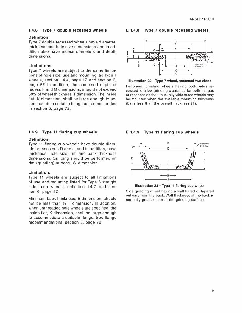
1.4.8 Type 7 double recessed wheels
Definition: Type 7 double recessed wheels have diameter, thickness and hole size dimensions and in ad-dition also have recess diameters and depth dimensions.
Limitations: Type 7 wheels are subject to the same limita-tions of hole size, use and mounting, as Type 1 wheels, section 1.4.4, page 17, and section 6, page 87. In addition, the combined depth of recess F and G dimensions, should not exceed 50% of wheel thickness, T dimension. The inside flat, K dimension, shall be large enough to ac-commodate a suitable flange as recommended in section 5, page 72.
1.4.9 Type 11 flaring cup wheels
Definition: Type 11 flaring cup wheels have double diam-eter dimensions D and J, and in addition, have thickness, hole size, rim and back thickness dimensions. Grinding should be performed on rim (grinding) surface, W dimension.
Limitation: Type 11 wheels are subject to all limitations of use and mounting listed for Type 6 straight sided cup wheels, definition 1.4.7, and sec-tion 6, page 87.
Minimum back thickness, e dimension, should not be less than 1/4 T dimension. In addition, when unthreaded hole wheels are specified, the inside flat, K dimension, shall be large enough to accommodate a suitable flange. See flange recommendations, section 5, page 72.
E 1.4.8 Type 7 double recessed wheels
TE
F
GK
D
K
H GRINDINGSURFACE
P
P
C
C
Illustration 22 – Type 7 wheel, recessed two sides
Peripheral grinding wheels having both sides re-cessed to allow grinding clearance for both flanges or recessed so that unusually wide faced wheels may be mounted when the available mounting thickness (e) is less than the overall thickness (T).
E 1.4.9 Type 11 flaring cup wheels
T
W
E
J
DK
H
GRINDINGSURFACE
Illustration 23 – Type 11 flaring cup wheel
Side grinding wheel having a wall flared or tapered outward from the back. Wall thickness at the back is normally greater than at the grinding surface.

20
ANSI B7.1-2010
1.4.10 Type 12 dish wheels
Definition: Type 12 dish wheels have diameter, thickness, rim thickness and back thickness dimension. In addition, Type 12 wheels always have a sur-face thickness, U dimension. Grinding may be performed on both A and U dimensions.
Limitation: Minimum back thickness, e dimension, should be equal to or greater than 1/2 wheel thickness, T dimension, J and K dimensions shall be large enough to accommodate a suitable flange. See flange recommendations, section 5, page 72.
1.4.11 Type 13 saucer wheels
Definition: Type 13 saucer wheels have diameter, thick-ness, hole size and back thickness dimensions. Grinding shall be performed on wheel periphery, U dimensions, only.
Limitation: J and K dimensions shall be large enough to accommodate suitable flanges, see section 5, page 72. In addition, wheel thickness shall always equal e dimension.
E 1.4.11 Type 13 saucer wheels
R
T
U
E
K
D
H
J
GRINDINGSURFACE
R= U2
Illustration 25 – Type 13 saucer wheel
Peripheral grinding wheel known as a saucer, differ-ing from a Type 12 in that the cross-section is equal throughout (U=e). The grinding surface is always half-round with R=U/2.
E 1.4.10 Type 12 dish wheels
T
UA
EHJ
K
DGRINDINGSURFACE
Illustration 24 – Type 12 dish wheel
Side grinding wheel known as a dish, differing from a Type 11 in that the Type 12 always has a “U” di-mension. The “W” dimension of a Type 11 becomes the “A” dimension of a Type 12. The grinding may be performed on both the “A” and “U” surfaces.

21
ANSI B7.1-2010
1.4.12 Types 16, 17, 18, 18R and 19 cone and plug wheels
Definition: Type 16 cones have a curved side with a nose radius. Type 17 cones have straight sides with or without a nose radius. Type 18 and 18R plug wheels are cylindrical in shape with either a square or curved grinding end. Type 19 cone wheels are a combination of cone and plug type shapes and are usually specified where base dimension D in a Type 17 cone would not provide an adequate cross section of abrasive. All types of cone and plug wheels are manu-factured with blind hole threaded bushings and may be used on all surfaces except the flat mounting surface D.
Limitation: Cone and plug type wheels are mounted by being screwed onto a threaded machine spindle so that surface D seats firmly against an unrelieved, flat back-up flange. (See sec-tion 3.3.4, page 33.) The maximum volume of type 16 through 19 cones and plugs shall not be greater than 35 cubic inches (example: a 3″ diameter, 5″ thick (T) type 18 plug wheel). Also, the thickness shall not be less than the base diameter. (example: a 2″ diameter wheel shall not be less than 2″ thick.)
Exception: valve seat wheels, where the mounting spindle is an integral part of the pilot used to align the wheel with the valve seat surface during grinding, need not be mounted as described above.
E 1.4.12 Types 16, 17, 18, 18R and 19 cone and plug wheels
Type 16 — Cone, curved side. Type 17 — Cone, straightside, square tip.
Type 18 — Plug, square end. Type 18R — Plug, round end.
Type 19 — Plug, conical end, square tip.
R1 GRINDINGSURFACE
R
H
B
D
T
GRINDINGSURFACE
J
HD
TB
GRINDING SURFACE
DH
TB
RGRINDING SURFACE
DH
BT
GRINDINGSURFACE
HD
JBS
T
Illustration 26 – Various types of cone and plug wheels

22
ANSI B7.1-2010
1.4.13 Types 20, 21, 22, 23, 24, 25, 26 re-lieved and/or recessed wheels
Definition: Types 20 through 26 relieved and/or recessed wheels have diameter, thickness, hole size, recess diameter and depth dimensions, and in addition may have tapered relief on one or both sides.
Limitation: Types 20 through 26 wheels are subject to the same limitations of use and mounting as Type 1 wheels, definition 1.4.4, page 17 and section 6, page 87.
Tapered relief depths shall be considered as recesses and added to straight recess depth or depths for determination of total wheel recess depth. Total recess depths should not exceed 50% of wheel thickness, T dimension. Dimen-sion K shall be large enough to accommodate a suitable flange as recommended in section 5, page 72.
1.4.14 Types 27 and 28 depressed center wheels
Definition: Types 27 and 28, depressed center wheels, have diameter, thickness and hole size di-mensions. Both types are reinforced, organic bonded wheels having depressed centers which permit grinding without interference with the mounting.
Type 27 wheels are manufactured with flat grinding rims or faces and are designed for side grinding, when used at a slight angle to the workpiece, or peripheral grinding, including small cutting-off and shallow notching opera-tions. When grinding masonry and concrete surfaces, such as ceilings and walls, they may be used flat. Such wheels have deeper than normal depressed centers for flat blending.
Type 28 wheels have saucer-shaped grinding rims and are designed for corner grinding and side grinding, and shall not be used for cutting-off or notching operations.
E 1.4.13 Types 20, 21, 22, 23, 24, 25, 26 relieved and/or recessed wheels
K
T
A
E
F N
GO
DK
H
*GRINDINGSURFACE
Type 26 — Relieved and recessed both sides.
T
F NA
E OK
K
H
D
*GRINDINGSURFACE
Type 25 — Relieved and recessed one side, relieved other side.
* T
NF
E
A
G H
K
K
D
GRINDINGSURFACE
Type 24 — Relieved and recessed one side, recessed other side.
*T
NFA
E
KD
HGRINDINGSURFACE
Type 23 — Relieved and recessed same side.
Type 22 — Relieved one side, recessed other side.
* T
E N A
F
DK
HK
GRINDINGSURFACE
Type 21 — Relieved two sides.
TE
NA
O HK
DK
GRINDINGSURFACE
Type 20 — Relieved one side.
T
AN
E
D
H
K
GRINDINGSURFACE
* For details of relationship between “P” (recess di-ameter) and “K” (inside flat) see illustration 20, page 18.
Illustration 27 – Various types of relieved and/or recessed wheels
E 1.4.14 Types 27 and 28 depressed center wheels
Type 27
Type 28U = E
U
V1E O
K
D
J
HY
GRINDINGSURFACE
GRINDINGSURFACE
U = E
U
OE
K
D
YH
Illustration 28 – Types 27 and 28 wheels, depressed center
Wheels are generally used on right angle head portable grinders.

23
ANSI B7.1-2010
Limitation: Special supporting, back adaptor and inside flange nuts are required for the proper mount-ing of these types of wheels, see section 6.15, page 96.
Mounts which are affixed to the wheel by the manufacturer may not require an inside nut and shall not be reused.
It is the user/owner’s responsibility to ensure wheels with this type mount fit inside the guard according to section 4.
1.4.15 Type 27 abrasive flap disc wheels
Construction consists of a reinforced organic bonded wheel shape with a depressed center metal reinforced arbor hole. Grinding portion consists of abrasive coated cloth pieces which are layered and glued on the peripheral portion of the bottom side.
Common shapes have flat and tapered layered coated abrasive grinding surfaces.
1.4.16 Type 27A depressed center wheels
Definition: Type 27A depressed center, cutting-off wheels have diameter, thickness and hole size dimen-sions. They are reinforced, organic bonded, off-set hub type wheels, usually 16″ diameter and larger, specially designed for use on cutting-off machines where mounting nut or outer flange interference cannot be tolerated.
Limitation: See section 5.1, page 72, and illustration 30 for mounting details.
1.4.17 Type 29 wheels
Definition: Type 29 grinding wheels have reversed saucer shaped grinding rims and are designed for blending (stock removal which leaves a smooth finish). They shall not be used for cutting off or notching applications.
E 1.4.16 Type 27A depressed center wheels
Illustration 30 – Type 27A wheel showing typical mounting details
E 1.4.17 Type 29 wheels
DH
K
GrindingSurface
U
Illustration 31 – Type 29 wheels
E 1.4.15 Type 27 abras ive f lap d isc wheels
GRINDINGSURFACE
Illustration 29 – Type 27 abrasive flap disc wheels, tapered and flat grinding surfaces

24
ANSI B7.1-2010
1.4.18 Cutting-off wheels
Definition: Cutting-off wheels have diameter, thickness, and hole size dimensions. They may be metal or organic bonded abrasives of the non-rein-forced, reinforced, heavily reinforced or metal center type.
(a) Non-reinforced cutting-off wheels are de-signed to withstand only centrifugal, radial and tangential cutting forces in the plane of the wheel.
(b) Reinforced cutting-off wheels are strong in the plane of the wheel and are better able to withstand some lateral and twisting forces.
(c) Heavily reinforced wheels have greater amounts of reinforcement than category (b) and are intended for use on heavy duty, high speed applications where the cutting plane is not fixed.
(d) Metal centered wheels may be used on any of the aforementioned cutting-off opera-tions.
Limitation: Cutting-off wheels are subject to all limitations of mounting and use listed for Type 1 wheels, definition 1.4.4, page 17, and section 6, page 87. In addition, cutting-off wheels are recommended only for use on specially designed and guarded machines and are subject to the following maxi-mum thickness and hole size limitations.
Wheel Diameter Maximum Thickness
4″ and Smaller 1/8″larger than 4″ to 6″ 3/16″larger than 6″ to 12″ 1/4″larger than 12″ to 23″ 3/8″larger than 23″ to 48″ 1/2″larger than 48″ 5/8″
Maximum hole size for cutting-off wheels should not be larger than 1/4 wheel diameter.
E 1.4.18 Cutting-off wheels
(a) Wheels with webbing, fabric or filament around the flange area only are classified as non-reinforced wheels. Non-reinforced cutting-off wheels are intended for use on standard speed machines where the cutting plane is controlled and the workpiece is se-cured to prevent movement. Non-reinforced cutting-off wheels are not designed for use on portable machines.
(b) Reinforced cutting-off wheels may be used on the same applications as non-reinforced wheels as well as other standard speed low horsepower applications where the cutting plane is not fixed such as hand-held por-table electric saws and grinders.
(c) Typical applications for heavily reinforced cutting-off wheels are swing frame or locked-down-head-chop saws and especially high-speed gasoline powered saws.
(d) Metal centered cutting-off wheels may be steel or powdered metal centers with con-tinuous or segmental abrasive rims.
Illustration 32 – A sample of a wet machine used for horizontal cutting-off

25
ANSI B7.1-2010
1.4.19 Mounted wheels
Definition: Mounted wheels, usually 2″ diameter or smaller, and of various shapes, may be either organic or inorganic bonded abrasive wheels. They are secured to plain or threaded mandrels.
Limitation: See section 10, page 117, for safe operation and speeds for mounted wheels.
1.4.20 Threaded hole cup wheels
Definition: Threaded hole cup wheels Types 6 and 11 are designed for use on vertical, right angle head, or flexible shaft portable grinders. They have one central threaded bushing, securely anchored in place. They are mounted by being screwed onto a threaded machine spindle so that the wheel back seats firmly against an unrelieved flat back flange.
Limitation: Threaded hole cup wheel mounting should not be used with wheels larger than 6″ diameter for portable applications. However, it is recog-nized that some swing frame applications do require larger than 6″ diameter threaded hole cup wheels. Back flanges used in mounting threaded hole cup wheels shall be flat and unrelieved.
Grinding should be performed on the grinding surface only.
1.4.21 Tuck pointing wheels
Definition: Tuck pointing wheels are Type 1 reinforced organic bonded wheels and have diameter, thickness and hole size dimensions.
Limitation: Tuck pointing wheels are subject to the same limitations of use and mounting as Type 1 wheels, definition 1.4.4, page 17, and section 6, page 87.
E 1.4.19 Mounted wheels
Illustration 33 – Typical examples of grinding wheels known as mounted wheels
E 1.4.20 Threaded hole cup wheels
Grinding surface
Illustration 34 – A cup wheel with a prong anchor bushing (anchor prong bushing)
Grinding surface
Illustration 35 – A cup wheel with a full back bushing

26
ANSI B7.1-2010
1.4.22 Modified Types 6 and 11 wheels (terrazzo)
Definition: Some Types 6 and 11 cup wheels used in the terrazzo trade have tapered K dimensions to match a special tapered flange furnished by the machine builder.
Limitation: These wheels shall be mounted only with a special tapered flange.
1.5 Abrasive wheels for use on portable air grinding machines
Abrasive wheels for use on portable air grind-ing machines shall conform in type and di-mension to the specifications listed in ANSI B186.1 Safety Code for Portable Air Tools, latest edition.
Exception: It is recognized that wheels other than those listed exist or may evolve through technology. Such wheels shall be used only if either of the following conditions are met:
(1) Where, after consultation and recommen-dation from the wheel manufacturer and the grinding machine manufacturer, safety provisions consistent with this standard are made.
(2) Where the grinding machine is designed and rated for the specific wheel, and proper safety provisions consistent with this stan-dard are used.
E 1.4.22 Modified Types 6 and 11 wheels (terrazzo)
Tapered “K” Dimension Tapered “K” Dimension
Type 6 Wheel (Terrazzo) Type 11 Wheel (Terrazzo)
Illustration 36 – Typical examples of modified Types 6 and 11 wheels (terrazzo) showing tapered
K dimensions