safety reports series no.30 - publications - international atomic
TRANSCRIPT

S a f e t y R e p o r t s S e r i e sN o. 3 0
Accident Analysisfor Nuclear Power Plants
with Pressurized Water Reactors

IAEA SAFETY RELATED PUBLICATIONS
IAEA SAFETY STANDARDS
Under the terms of Article III of its Statute, the IAEA is authorized to establish standardsof safety for protection against ionizing radiation and to provide for the application of thesestandards to peaceful nuclear activities.
The regulatory related publications by means of which the IAEA establishes safetystandards and measures are issued in the IAEA Safety Standards Series. This series coversnuclear safety, radiation safety, transport safety and waste safety, and also general safety (thatis, of relevance in two or more of the four areas), and the categories within it are SafetyFundamentals, Safety Requirements and Safety Guides.
Safety Fundamentals (blue lettering) present basic objectives, concepts and principles ofsafety and protection in the development and application of nuclear energy for peacefulpurposes.
Safety Requirements (red lettering) establish the requirements that must be met to ensuresafety. These requirements, which are expressed as ‘shall’ statements, are governed bythe objectives and principles presented in the Safety Fundamentals.
Safety Guides (green lettering) recommend actions, conditions or procedures for meetingsafety requirements. Recommendations in Safety Guides are expressed as ‘should’ state-ments, with the implication that it is necessary to take the measures recommended orequivalent alternative measures to comply with the requirements.
The IAEA’s safety standards are not legally binding on Member States but may beadopted by them, at their own discretion, for use in national regulations in respect of their ownactivities. The standards are binding on the IAEA in relation to its own operations and on Statesin relation to operations assisted by the IAEA.
Information on the IAEA’s safety standards programme (including editions in languagesother than English) is available at the IAEA Internet site
www-ns.iaea.org/standards/or on request to the Safety Co-ordination Section, IAEA, P.O. Box 100, A-1400 Vienna,Austria.
OTHER SAFETY RELATED PUBLICATIONS
Under the terms of Articles III and VIII.C of its Statute, the IAEA makes available andfosters the exchange of information relating to peaceful nuclear activities and serves as anintermediary among its Member States for this purpose.
Reports on safety and protection in nuclear activities are issued in other series, inparticular the IAEA Safety Reports Series, as informational publications. Safety Reports maydescribe good practices and give practical examples and detailed methods that can be used tomeet safety requirements. They do not establish requirements or make recommendations.
Other IAEA series that include safety related publications are the Technical ReportsSeries, the Radiological Assessment Reports Series, the INSAG Series, the TECDOCSeries, the Provisional Safety Standards Series, the Training Course Series, the IAEAServices Series and the Computer Manual Series, and Practical Radiation Safety Manualsand Practical Radiation Technical Manuals. The IAEA also issues reports on radiologicalaccidents and other special publications.

ACCIDENT ANALYSISFOR NUCLEAR POWER PLANTS
WITH PRESSURIZED WATER REACTORS

The following States are Members of the International Atomic Energy Agency:
The Agency’s Statute was approved on 23 October 1956 by the Conference on the Statuteof the IAEA held at United Nations Headquarters, New York; it entered into force on 29 July 1957.The Headquarters of the Agency are situated in Vienna. Its principal objective is “to accelerate andenlarge the contribution of atomic energy to peace, health and prosperity throughout the world’’.
© IAEA, 2003
Permission to reproduce or translate the information contained in this publication may beobtained by writing to the International Atomic Energy Agency, Wagramer Strasse 5, P.O. Box 100,A-1400 Vienna, Austria.
Printed by the IAEA in AustriaNovember 2003STI/PUB/1162
AFGHANISTANALBANIAALGERIAANGOLAARGENTINAARMENIAAUSTRALIAAUSTRIAAZERBAIJANBANGLADESHBELARUSBELGIUMBENINBOLIVIABOSNIA AND
HERZEGOVINABOTSWANABRAZILBULGARIABURKINA FASOCAMEROONCANADACENTRAL AFRICAN
REPUBLICCHILECHINACOLOMBIACOSTA RICACÔTE D’IVOIRECROATIACUBACYPRUSCZECH REPUBLICDEMOCRATIC REPUBLIC
OF THE CONGODENMARKDOMINICAN REPUBLICECUADOREGYPTEL SALVADORERITREAESTONIAETHIOPIAFINLANDFRANCEGABONGEORGIAGERMANYGHANA
GREECEGUATEMALAHAITIHOLY SEEHONDURASHUNGARYICELANDINDIAINDONESIAIRAN, ISLAMIC REPUBLIC OF IRAQIRELANDISRAELITALYJAMAICAJAPANJORDANKAZAKHSTANKENYAKOREA, REPUBLIC OFKUWAITKYRGYZSTANLATVIALEBANONLIBERIALIBYAN ARAB JAMAHIRIYALIECHTENSTEINLITHUANIALUXEMBOURGMADAGASCARMALAYSIAMALIMALTAMARSHALL ISLANDSMAURITIUSMEXICOMONACOMONGOLIAMOROCCOMYANMARNAMIBIANETHERLANDSNEW ZEALANDNICARAGUANIGERNIGERIANORWAYPAKISTANPANAMA
PARAGUAYPERUPHILIPPINESPOLANDPORTUGALQATARREPUBLIC OF MOLDOVAROMANIARUSSIAN FEDERATIONSAUDI ARABIASENEGALSERBIA AND MONTENEGROSEYCHELLESSIERRA LEONESINGAPORESLOVAKIASLOVENIASOUTH AFRICASPAINSRI LANKASUDANSWEDENSWITZERLANDSYRIAN ARAB REPUBLICTAJIKISTANTHAILANDTHE FORMER YUGOSLAV
REPUBLIC OF MACEDONIATUNISIATURKEYUGANDAUKRAINEUNITED ARAB EMIRATESUNITED KINGDOM OF
GREAT BRITAIN AND NORTHERN IRELAND
UNITED REPUBLICOF TANZANIA
UNITED STATES OF AMERICAURUGUAYUZBEKISTANVENEZUELAVIETNAMYEMENZAMBIAZIMBABWE

SAFETY REPORTS SERIES No. 30
ACCIDENT ANALYSISFOR NUCLEAR POWER PLANTS
WITH PRESSURIZED WATER REACTORS
INTERNATIONAL ATOMIC ENERGY AGENCYVIENNA, 2003
IAEA Library Cataloguing in Publication Data
Accident analysis for nuclear power plants with pressurized waterreactors. — Vienna : International Atomic Energy Agency, 2003.
p. ; 24 cm. — (Safety reports series, ISSN 1020–6450 ; no. 30)STI/PUB/1162ISBN 92–0–110603–3Includes bibliographical references.
1. Pressurized water reactors. 2. Nuclear power plants — Accidents.I. International Atomic Energy Agency. II. Series.
IAEAL 03–00333

FOREWORD
Deterministic safety analysis (frequently referred to as accident analysis) isan important tool for confirming the adequacy and efficiency of provisions withinthe defence in depth concept for the safety of nuclear power plants (NPPs).Owing to the close interrelationship between accident analysis and safety, ananalysis that lacks consistency, is incomplete or of poor quality is considered tobe a safety issue for a given NPP. Developing IAEA guidance publications foraccident analysis is thus an important step towards resolving this issue.
Requirements and guidance pertaining to the scope and content ofaccident analysis have, in the past, been partially described in various IAEAreports. Several guidance documents relevant to water moderated, watercooled power reactors (WWERs) and high power boiling reactors withpressurized channels of Russian design known as RBMKs have beendeveloped within the IAEA’s Extra-budgetary Programme on the Safety ofWWER and RBMK Nuclear Power Plants. To a certain extent, accidentanalysis is also covered in several publications of the revised NUSS Series, forexample, in the Safety Requirements on Safety of Nuclear Power Plants:Design (NS-R-1) and in the Safety Guide on Safety Assessment andVerification for Nuclear Power Plants (NS-G-1.2). For consistency with thesepublications, the IAEA has developed a series of Safety Reports on AccidentAnalysis for Nuclear Power Plants. Many experts have contributed to thedevelopment of these Safety Reports. In addition to several consultants’meetings, comments were collected from more than fifty selectedorganizations. These reports were also reviewed at the IAEA TechnicalCommittee Meeting on Accident Analysis held in Vienna from 30 August to3 September 1999.
These Safety Reports aim to provide practical guidance for performingaccident analysis. The guidance is based on present good practice worldwide.The reports cover all the steps required for accident analyses, i.e. selection ofinitiating events and acceptance criteria, selection of computer codes andmodelling assumptions, preparation of input data and presentation of thecalculation results. The reports also discuss the various aspects that need to beconsidered to ensure that an accident analysis is of acceptable quality.
The first volume of the series is intended to be as generally applicable aspossible to all reactor types.The specific features of individual reactor types aretaken into account in the subsequent reports in the series. The reactor types tobe covered include pressurized water reactors (PWRs), boiling water reactors(BWRs), pressurized heavy water reactors (PHWRs) or more specificallyPHWRs of Canadian design known as CANDU, and RBMKs. The presentreport is devoted to specific guidance for PWRs.
The report is intended for use primarily by analysts co-ordinating,performing or reviewing accident analysis for NPPs, on both the utility and theregulatory sides. The report will also be used as a background publication forrelevant IAEA activities, such as training courses and workshops.
The IAEA staff member responsible for this publication was J. Mišák ofthe Division of Nuclear Installation Safety.
EDITORIAL NOTE
Although great care has been taken to maintain the accuracy of information con-tained in this publication, neither the IAEA nor its Member States assume any responsi-bility for consequences which may arise from its use.
The mention of names of specific companies or products (whether or not indicatedas registered) does not imply any intention to infringe proprietary rights, nor should it beconstrued as an endorsement or recommendation on the part of the IAEA.
CONTENTS
1. INTRODUCTION . . . . . . . . . . . . . . . . . . . . . . . . . . . . . . . . . . . . . . . . . 1
1.1. Background . . . . . . . . . . . . . . . . . . . . . . . . . . . . . . . . . . . . . . . . . . . 11.2. Objective . . . . . . . . . . . . . . . . . . . . . . . . . . . . . . . . . . . . . . . . . . . . . 21.3. Scope . . . . . . . . . . . . . . . . . . . . . . . . . . . . . . . . . . . . . . . . . . . . . . . . 21.4. Structure . . . . . . . . . . . . . . . . . . . . . . . . . . . . . . . . . . . . . . . . . . . . . 3
2. INITIATING EVENTS AND THEIR CATEGORIZATION . . . . 4
3. ACCEPTANCE CRITERIA . . . . . . . . . . . . . . . . . . . . . . . . . . . . . . . . . 8
3.1. Acceptance criteria for transients . . . . . . . . . . . . . . . . . . . . . . . . 83.2. Acceptance criteria for design basis accidents . . . . . . . . . . . . . . 83.3. Acceptance criteria for all accidents leading to
containment pressurization . . . . . . . . . . . . . . . . . . . . . . . . . . . . . . 93.4. Acceptance criteria for pressurized thermal shock
analysis of accidents . . . . . . . . . . . . . . . . . . . . . . . . . . . . . . . . . . . . 103.5. Acceptance criteria for accidents occuring during shutdown . . 103.6. Acceptance criteria for severe accidents . . . . . . . . . . . . . . . . . . . 10
4. SELECTION OF INITIAL AND BOUNDARY CONDITIONS . . 11
5. ANALYSIS OF CORE COOLING AND SYSTEM PRESSURE FOR REACTIVITY INDUCED ACCIDENTS . . . . . . . . . . . . . . . . 14
5.1. Control rod ejection . . . . . . . . . . . . . . . . . . . . . . . . . . . . . . . . . . . . 145.2. Control rod withdrawal . . . . . . . . . . . . . . . . . . . . . . . . . . . . . . . . . 165.3. Control rod malfunction . . . . . . . . . . . . . . . . . . . . . . . . . . . . . . . . 175.4. Incorrect connection of an inactive
reactor coolant system loop . . . . . . . . . . . . . . . . . . . . . . . . . . . . . 185.5. Boron dilution . . . . . . . . . . . . . . . . . . . . . . . . . . . . . . . . . . . . . . . . . 195.6. Inadvertent loading of a fuel assembly into
an improper position . . . . . . . . . . . . . . . . . . . . . . . . . . . . . . . . . . . 20
6. ANALYSIS OF CORE COOLING AND SYSTEM PRESSURE FOR A DECREASE OF REACTOR COOLANT FLOW . . . . . . . 21
6.1. Single or multiple MCP trip . . . . . . . . . . . . . . . . . . . . . . . . . . . . . 21
6.2. Inadvertent closure of a main isolation valve in a reactor coolant system loop . . . . . . . . . . . . . . . . . . . . . . . . . . . . 22
6.3. Seizure of one main circulation pump or shaft break of one main circulation pump . . . . . . . . . . . . . . . . . 22
6.4. Coolant flow blockage in a fuel assembly . . . . . . . . . . . . . . . . . . 23
7. ANALYSIS OF SYSTEM PRESSURE FOR INCREASE OF REACTOR COOLANT INVENTORY . . . . . . . . 23
7.1. Inadvertent actuation of the emergency core cooling system . . 237.2. Malfunctions in the chemical and volume control systems . . . 24
8. ANALYSIS OF CORE COOLING AND SYSTEM PRESSURE FOR INCREASE OF HEAT REMOVAL BY THE SECONDARY SIDE . . . . . . . . . . . . . . . . . . . . . . . . . . . . . . . 25
8.1. Steam line breaks . . . . . . . . . . . . . . . . . . . . . . . . . . . . . . . . . . . . . . 258.2. Inadvertent opening of steam relief valves . . . . . . . . . . . . . . . . . 278.3. Secondary pressure control malfunction with an
increase of steam flow rate . . . . . . . . . . . . . . . . . . . . . . . . . . . . . . 288.4. Feedwater system malfunction . . . . . . . . . . . . . . . . . . . . . . . . . . . 28
9. ANALYSIS OF CORE COOLING AND SYSTEM PRESSURE FOR DECREASE OF HEAT REMOVAL BY THE SECONDARY SIDE . . . . . . . . . . . . . . . . . . . . . . . . . . . . . . . 29
9.1. Feedwater line break . . . . . . . . . . . . . . . . . . . . . . . . . . . . . . . . . . . 299.2. Feedwater pump trip . . . . . . . . . . . . . . . . . . . . . . . . . . . . . . . . . . . 309.3. Reduction of steam flow from steam generator
for various reasons . . . . . . . . . . . . . . . . . . . . . . . . . . . . . . . . . . . . . 31
10. ANALYSIS OF CORE COOLING FOR LOCAs . . . . . . . . . . . . . . . 31
10.1. Initiating events and safety aspects . . . . . . . . . . . . . . . . . . . . . . . 3110.2. Specific suggestions for analysis . . . . . . . . . . . . . . . . . . . . . . . . . . 33
11. ANALYSIS OF PRIMARY TO SECONDARY SYSTEM LEAKAGE . . . . . . . . . . . . . . . . . . . . . . . . . . . . . . . . . . . . . . . 35
11.1. Initiating events and safety aspects . . . . . . . . . . . . . . . . . . . . . . . 3511.2. Specific suggestions for analysis . . . . . . . . . . . . . . . . . . . . . . . . . . 36

12. ANALYSIS OF ANTICIPATED TRANSIENTS WITHOUT SCRAM . . . . . . . . . . . . . . . . . . . . . . . . . . . . . . . . . . . . . . . . 38
12.1. Initiating events and safety aspects . . . . . . . . . . . . . . . . . . . . . . . 3812.2. Specific suggestions for analysis . . . . . . . . . . . . . . . . . . . . . . . . . . 39
13. ANALYSIS OF BORON DILUTION ACCIDENTS . . . . . . . . . . . . 41
13.1. Initiating events and safety aspects . . . . . . . . . . . . . . . . . . . . . . . 4113.2. Specific suggestions for analysis . . . . . . . . . . . . . . . . . . . . . . . . . . 42
14. ANALYSIS OF PRESSURIZED THERMAL SHOCKS . . . . . . . . 43
14.1. Initiating events and safety aspects . . . . . . . . . . . . . . . . . . . . . . . 4314.2. Specific suggestions for analysis . . . . . . . . . . . . . . . . . . . . . . . . . . 44
15. ANALYSIS OF RESIDUAL HEAT REMOVAL DEGRADATION DURING SHUTDOWN OPERATIONAL MODES . . . . . . . . . . . . . . . . . . . . . . . . . . . . . . . . . . 46
15.1. Initiating events and safety aspects . . . . . . . . . . . . . . . . . . . . . . . 4615.2. Specific suggestions for analysis . . . . . . . . . . . . . . . . . . . . . . . . . . 47
16. ANALYSIS OF PRESSURE–TEMPERATURE TRANSIENTS IN THE CONTAINMENT . . . . . . . . . . . . . . . . . . . . 50
16.1. Short term containment pressurization . . . . . . . . . . . . . . . . . . . . 5016.2. Long term pressure–temperature transients . . . . . . . . . . . . . . . . 52
17. ANALYSIS OF RADIOACTIVITY TRANSPORT DURING DESIGN BASIS ACCIDENTS . . . . . . . . . . . . . . . . . . . . . 55
17.1. Initiating events and safety aspects . . . . . . . . . . . . . . . . . . . . . . . 5517.2. Specific suggestions for analysis . . . . . . . . . . . . . . . . . . . . . . . . . . 55
18. ANALYSIS OF SEVERE ACCIDENTS . . . . . . . . . . . . . . . . . . . . . . . 57
18.1. Initiating events and safety aspects . . . . . . . . . . . . . . . . . . . . . . . 5718.2. Specific suggestions for analysis . . . . . . . . . . . . . . . . . . . . . . . . . . 58
19. SUGGESTIONS ON REPORTING OF RESULTS . . . . . . . . . . . . . 60

REFERENCES . . . . . . . . . . . . . . . . . . . . . . . . . . . . . . . . . . . . . . . . . . . . . . . . . 63CONTRIBUTORS TO DRAFTING AND REVIEW . . . . . . . . . . . . . . . . 65

1. INTRODUCTION
1.1. BACKGROUND
Consistent with the revised Safety Standards Series, in particular with theSafety Requirements on Safety of Nuclear Power Plants: Design [1] and theSafety Guide on Safety Assessment and Verification [2], the IAEA hasdeveloped a Safety Report on Accident Analysis of Nuclear Power Plantscontaining a comprehensive description of the general methodology foraccident analysis [3]. The objective of that Safety Report is to establish a set ofpractical suggestions based on the best practice worldwide for performingaccident analysis for nuclear power plants (NPPs). The following items arecovered in that report:
(1) Classification of initiating events and acceptance criteria;(2) Methodology used for the analysis;(3) Types of accident analysis;(4) Computer codes;(5) User effects on the analysis;(6) Input data preparation;(7) Presentation and evaluation of results;(8) Quality assurance.
Annexes to Ref. [3] provide examples of the practical application ofaccident analysis; they specify and characterize the main steps in performingaccident analysis, provide more discussion on and examples of uncertaintyanalysis, give a practical example of the preparation of input data for analysisand of the production of the corresponding documents. The annexes alsocontain references to the typical computer codes, provide an extensive list ofcodes for accident analysis and include explanations of technical terms used inthe main report and its appendices. That Safety Report [3] is general in natureand does not focus exclusively on any single reactor type.
More specific guidance on performing accident analysis depends on thecharacteristics of the NPP in question and can only be developed for specificreactor designs or, in a more general manner, for a group of reactor designs.Such design specific guidance documents are being developed as separateSafety Reports. The reactor types to be covered include pressurized waterreactors (PWRs), boiling water reactors (BWRs), pressurized heavy waterreactors (PHWRs) or, more specifically, PHWRs of Canadian design known as
1
CANDUs, and high power boiling reactors with pressurized channels (ofRussian design) known as RBMKs.
1.2. OBJECTIVE
The objective of the present report is to provide specific guidance foraccident analysis for NPPs with PWRs, taking into account the specific designfeatures of these reactors. This guidance contains a detailed list of initiatingevents with their direct causes and an overview of the safety aspects of theevent leading to potential degradation of the barriers against release of theradioactive material. Licensing type safety analyses, aimed at demonstration ofsufficient safety margins, are mainly addressed. The analysis methodology forthe various events differs mainly in the selection of the acceptance criteria andin the level of conservatism required in the analysis. Examples of acceptancecriteria are also provided. Conservative assumptions (i.e. those leading to morepessimistic results) for typical initial parameters and boundary conditions areindicated. Suggestions on the selection of acceptance criteria as well as initialconditions and boundary conditions are provided. Specific methodologicalinstructions on how to perform the analysis of individual events are given. Listsof output parameters to be presented for various events are suggested.
This report is mostly based on the experience of the experts involved,with considerable use of other relevant IAEA documents [4–9] and nationaldocuments [10–16].
1.3. SCOPE
In a similar way to the first volume of this series, Ref. [3], this PWRspecific volume also deals only with ‘internal’ events originating in the reactoror in its associated process systems. It does not cover originating eventsaffecting broad areas of the plant (often called internal and external hazards),such as fires, floods (internal and external), earthquakes and aircraft crashes.However, analysis of the consequences of these events from a thermohydraulicpoint of view is partially covered by the present guidance. The emphasis in thisguidance is on the transient behaviour of the reactor and its systems, includingthe containment and/or confinement.
The main focus of the analyses is towards the thermohydraulic aspects ofthe transients considered. The neutronic and radiological aspects are alsocovered to some extent. Limited consideration is given to structural(mechanical) aspects.
2
This report deals with both best estimate and conservative accidentanalyses. Although originally all the NPPs were licensed using a fully conser-vative approach (conservative code and conservative input data), such anapproach can be misleading in a number of applications. Thus the use of bestestimate computer codes and tools is encouraged, but always in such a way thatsufficient safety margins are ensured for all applications aimed at the demon-stration of plant safety.
The report covers both design basis accident (DBA) and beyond designbasis accident (BDBA) situations; however, BDBA events are covered to amuch lesser extent, since specific guidance documents are envisaged to coverthe complex area of severe accidents (SAs) with significant core damage.
The information provided by this report is intended primarily for codeusers performing accident analysis. Regulatory bodies are encouraged to usethis report as the basis for their national requirements. It may also be used byanalysts as a reference for contacts with the national regulatory body or for theformulation of detailed company procedures for analysts.
This report in the series, along with all the other design specific reports, isintended to be, to a large extent, a self-standing publication. Nevertheless, toavoid repetition of suggestions included already in the general guidance, it isadvisable for users to read the first volume in the series, Ref. [3], before usingany of the design specific guidance reports.
1.4. STRUCTURE
The structure of the present report is consistent with that of the firstSafety Report in the series, Ref. [3]. Naturally, the content of the sections andthe level of detail take into account the design specific features of PWRs.Whenever considered to be important, reference is made to the generalguidance given in Ref. [3]. In addition to this introductory section, there are 18sections in this report.
Section 2 deals with the proper selection and categorization of initiatingevents. The characteristic physical phenomena are the basis for the selectionand classification of the events. According to the frequency of their occurrence,initiating events are put into one of two categories, either anticipatedoperational occurrences (AOOs), also known as transients (Ts) or accidents(As). Accidents are further subdivided into DBAs, BDBAs and SAs. Anappropriate grouping of events, for which a similar approach can be used, isprovided.
In Section 3 the acceptance criteria for accident analysis applicable toPWRs are presented. Different sets of criteria for different categories of events
3

are given. Since setting up acceptance criteria rests with national regulatoryauthorities, the criteria provided in this report can only be understood asexamples.
Section 4 provides a short description of ways to ensure sufficient safetymargins by proper selection of the initial conditions and some boundaryconditions for the accident analysis. Suggestions are provided in relation to howthe various conditions should be transferred to the code input decks, inparticular for the conservative specification of initial and boundary conditions.
More detailed suggestions for analysis of different initiating events aredescribed in Sections 5–18. These suggestions are formulated for groups ofevents with similar phenomena occurring during the course of an event. Thelevel of detail is chosen in such a way as to avoid entering into features specificto individual plants. For each of the groups, initiating events and their safetyaspects are identified and specific suggestions for analysis are formulated.
Section 19 provides a list of the calculated parameters to be reported thatare specific to the different accident scenarios.
2. INITIATING EVENTS AND THEIR CATEGORIZATION
According to their frequency of occurrence [3], initiating events caneither be considered as AOOs, also called transients (Ts), or accidents (As).Accidents can be further subdivided into DBAs, BDBAs and SAs. Themethodology of analysis for various events differs mainly in the use ofdiverging acceptance criteria and also in the level of conservatism in theanalysis assumptions.
A typical categorization for groups of initiating events [3] can beproposed, consistently with Ref. [4], as follows:
(a) Reactivity induced accidents (RIAs):— Control rod (CR) ejection (A);— CR withdrawal (T);— CR malfunction (T);— Incorrect connection of an isolated reactor coolant system (RCS) loop,
if applicable (A);— Boron dilution due to a chemical and volume control system (CVCS)
malfunction (T);— Inadvertent loading of a fuel assembly into an improper position (A).
(b) Decrease of reactor coolant flow:
4

— Single or multiple reactor coolant pump (RCP) trips (T);— Inadvertent closure of a main isolation valve (MIV) in an RCS loop, if
applicable (T);— Seizure of one RCP (A);— Shaft break for one RCP (A);— Coolant flow blockage in the fuel assembly.
(c) Increase of reactor coolant inventory:— Inadvertent actuation of the emergency core cooling system (ECCS)
(T);— Malfunction of CVCS leading to reactor coolant inventory increase
(T).(d) Increase of heat removal by the secondary side:
— Steam line breaks (A);— Inadvertent opening of steam relief valves (T);— Secondary pressure control malfunction with increase of steam flow
rate (T);— Feedwater system malfunction leading to increase of heat removal (T).
(e) Decrease of heat removal by the secondary side:— Feedwater line break (A);— Feedwater pump trips (T);— Reduction of the steam flow from the steam generator (SG) (T).
(f) Decrease of reactor coolant inventory:— Inadvertent opening of the primary system isolating valves (A);— Spectrum of postulated pipe breaks — loss of coolant accidents
(LOCAs) (A);— Leaks from the primary to the secondary side of the SG (A);
(g) Anticipated transients without SCRAM (ATWS).
During the course of a transient or an accident, a number of differenteffects may challenge the integrity of the barriers against uncontrolled releaseof radioactivity, by affecting the three fundamental safety functions (control ofreactivity, removal of heat from the fuel and confinement of radioactivematerials). These effects are also called ‘safety aspects’ of the accident. Somepotential safety aspects are listed below, following the sequence of the foursuccessive barriers, covering the full spectrum of consequences, from transientsto DBAs to SAs:
— Reactor power excursions due to reactivity insertion;— Reactor re-criticality (local or global) after shutdown;— Fuel enthalpy and temperature rise;— Local fuel melting;
5
— Reduction of the departure from nucleate boiling ratio (DNBR) due toreduced coolant flow or due to increased temperature or decreasedpressure;
— Boiling crisis due to loss of coolant inventory;— Overheating of fuel cladding;— Zirconium–water reaction of the cladding;— Deformation of and/or damage to the fuel cladding;— Hydrogen production;— Major fuel melting and core degradation;— Primary or secondary system pressurization;— Pressure waves formed inside the reactor system acting on reactor
internals;— Pressurized thermal shock;— Reactor vessel melt-through;— Mechanical impact of the escaping coolant jet and the corresponding
reaction forces on plant components and systems;— Environmental impact of the escaping coolant on system and component
qualification requirements (humidity, temperature and radiation);— Direct coolant radioactivity releases due to containment bypass;— Containment pressurization;— Radioactivity releases from the containment;— Containment basemat melt-through.
Any initiating event may be analysed with respect to these safety aspects.Acceptance criteria, as discussed in Section 3, are basically related to thesesafety aspects. More details on safety aspects are also provided in Sections5–18.
As already discussed in the first Safety Report in this series, Ref. [3],different safety aspects may be related to a single internal initiating event. Forexample, various LOCAs lead to the degradation of core cooling and possiblyto fuel overheating. At the same time, LOCAs lead to containment pressurebuildup, radioactivity transport and possibly environmental releases. Undercertain conditions, safety injection may cause a significant temperaturereduction in the downcomer region of the reactor vessel, thus leading to apotential pressurized thermal shock (PTS). The boiling condensing regimeduring a LOCA may result in boron dilution by creating a slug of coolant of lowboron concentration in the primary circuit. Such a case would have thepotential for a reactivity accident. In some countries, complete failure ofreactor scram in the case of LOCAs is required to be studied as an ATWSsequence. For primary to secondary leakage accidents, which are a special caseof LOCAs, radioactive fission products can be directly transported to the
6

environment through the secondary side steam relief paths, thus leading to acontainment bypass. Each of these safety aspects requires differentassumptions for the analysis, at least a partially different methodology andoften even a different computer code.
For practical reasons, safety aspects and dominant phenomena are used asa basis to group the suggestions about methodologies in this report.Consequently, for each group it is possible to use the same computer code, toselect similar acceptance criteria and/or similar initial conditions, applyingsimilar methodologies with the results being presented in similar form.
The groups selected for this guidance are as follows:
— Analysis of core cooling and system pressure for various events;— Analysis for core cooling for LOCAs;— Analysis of containment bypass due to primary to secondary side leakage
accidents;— Analysis of ATWS;— Analysis of boron dilution;— Analysis of PTS;— Analysis of residual heat removal (RHR) degradation during shutdown
operational modes;— Analysis of pressure–temperature transients in containments;— Analysis of radioactivity transport during DBAs;— Analysis of SAs; in the present report, only very short guidance is
provided since separate guidance documents will be issued by the IAEAfor SAs.
For each group of events listed above, a more detailed list of initiatingevents is given in Sections 5–18 with their direct causes, categorized accordingto their frequency of occurrence. Safety aspects of the event leading to apotential degradation of barriers are summarized, and suggestions on theselection of acceptance criteria as well as of initial conditions are provided.Finally, some specific methodological instructions on how to perform theanalysis of individual events are provided.
Some suggestions, in particular the conservative selection of initial andother conditions for accident analysis, are mainly applicable to conservativeanalysis, which is typical for design or licensing analysis. The majority of theother suggestions is also applicable to best estimate analysis.
It is emphasized that most of the information given in this report is meantas examples of good practices, based on experience from several countries. Theguidance may not automatically apply to all the individual reactor designs,computer codes and selected approaches used in accident analysis.
7

3. ACCEPTANCE CRITERIA
The applicable acceptance criteria used in accident analysis typicallydepend on the objective of the analysis (e.g. design or licensing), on thefrequency of the initiating events, on the related safety aspects and on theexisting high level limits for accident consequences.Thus, different criteria existfor AOOs, for DBAs and for BDBAs or SAs. Acceptance criteria for accidentsare further differentiated for LOCAs, for ATWS and for other types ofaccident. Typical examples of acceptance criteria are given below.
3.1. ACCEPTANCE CRITERIA FOR TRANSIENTS
For transients it has to be demonstrated that the intrinsic features of thedesign and the systems automatically actuated by the instrumentation, particu-larly the reactor trip system, are sufficiently effective to ensure that:
(1) The probability of a boiling crisis anywhere in the core is low. This crite-rion is typically expressed by the requirement that there is a 95% proba-bility at the 95% confidence level that the fuel rod does not experience adeparture from nucleate boiling (DNB).The DNB correlation used in theanalysis needs to be based on experimental data that are relevant to theparticular core cooling conditions and fuel design.
(2) The pressure in the reactor coolant and main steam systems is maintainedbelow a prescribed value (typically 110% of the design pressure).
(3) There is no fuel melting anywhere in the core.
3.2. ACCEPTANCE CRITERIA FOR DESIGN BASIS ACCIDENTS
For DBAs it has to be demonstrated that the design specific engineeredsafety features are sufficiently effective to ensure that:
(4) The radially averaged fuel pellet enthalpy does not exceed the prescribedvalues (the values differ significantly among different reactor designs anddepend also on fuel burnup) at any axial location of any fuel rod. This cri-terion ensures that fuel integrity is maintained and energetic fuel disper-sion into the coolant will not occur (specific to RIAs).
(5) The fuel rod cladding temperature does not exceed a prescribed value(typically 1480°C). This criterion ensures that melting and embrittlementof the cladding are avoided.
8
(6) Fuel melting at any axial location of any fuel rod is limited (typically, nofuel melt is allowed or a maximum 10% melt of the fuel volume at the hotspot is accepted). This criterion ensures that substantial volumetricchanges of fuel and a release of radioactive elements will not occur.
(7) The pressure in the reactor coolant and in the main steam system is main-tained below a prescribed value (typically 135% of the design value forATWSs and 110% for other DBAs). This criterion ensures that the struc-tural integrity of the reactor coolant boundary is maintained.
(8) Calculated doses are below the limits for DBAs, assuming an event gen-erated iodine spike and an equilibrium iodine concentration for contin-ued power operation, and considering actual operational limits and con-ditions for the primary and secondary coolant activity.
In addition to criteria (4)–(8), particularly for design basis LOCAs, shortterm and long term core coolability should be ensured by fulfilling thefollowing five criteria:
(9) The fuel rod cladding temperature should not exceed a prescribed value(typically 1200°C); the value is limiting from the point of view of claddingintegrity following its quenching and is also important for avoiding astrong cladding–steam reaction, thus replacing criterion (5) which is validfor other accidents.
(10) The maximum local cladding oxidation should not exceed a prescribedvalue (typically 17–18% of the initial cladding thickness before oxida-tion).
(11) The total amount of hydrogen generated from the chemical reaction ofthe cladding with water or steam should not exceed a prescribed value(typically 1% of the hypothetical amount that would be generated if allthe cladding in the core were to react).
(12) Calculated changes in core geometry have to be limited in such a way thatthe core remains amenable to long term cooling, and the CRs need toremain movable.
(13) There should be sufficient coolant inventory for long term cooling.
3.3. ACCEPTANCE CRITERIA FOR ALL ACCIDENTS LEADING TOCONTAINMENT PRESSURIZATION
In addition to the relevant criteria given above, the following criteriaapply:
9

(14) The calculated peak containment pressure needs to be lower than thecontainment design pressure and the calculated minimum containmentpressure needs to be higher than the corresponding acceptable value.
(15) Differential pressures, acting on containment internal structuresimportant for containment integrity, have to be maintained at acceptablevalues.
3.4. ACCEPTANCE CRITERIA FOR PRESSURIZED THERMALSHOCK ANALYSIS OF ACCIDENTS
Specific acceptance criteria for PTS analysis should apply, as follows:
(16) There will be no initiation of a brittle fracture or ductile failure from apostulated defect of the reactor pressure vessel (RPV) during the plantdesign life for the whole set of anticipated transients and postulated acci-dents.
3.5. ACCEPTANCE CRITERIA FOR ACCIDENTS OCCURRINGDURING SHUTDOWN
The operational modes considered have several barriers partiallydegraded (reactor pressure vessel closed or open, containment closed or open).Besides generally applicable criteria, such as (8), the following specific (morestringent in the case of degraded barriers) criteria have to apply:
(17) If both the reactor and the containment are closed, the fuel cladding tem-perature and oxidation have to be limited to the same values as those fora LOCA.
(18) If one of the barriers (either reactor or containment) is open while theother is closed, uncovery of the fuel in the reactor needs to be avoided.
(19) If both barriers (reactor and containment) are open, both coolant boilingin the core and fuel uncovery need to be avoided.
3.6. ACCEPTANCE CRITERIA FOR SEVERE ACCIDENTS
Acceptance criteria for SAs are less prescriptive than the criteria forDBAs. Typically, the criterion is considered in relation to the very lowprobability associated with an SA.
10

Examples of more specific criteria applicable for SAs with non-negligibleprobability are as follows:
(20) There should be no failure of the containment because of pressure andtemperature loads.
(21) There should be no immediate health effects on the population.(22) For long term effects the 137Cs release limit needs to be below the pre-
scribed value (e.g. 100 TBq), and all the other nuclides together are not tocause a larger danger after the time period specified (e.g. three months).
4. SELECTION OF INITIAL AND BOUNDARY CONDITIONS
There are a number of input parameters for analysis, corresponding to theNPP status prior to the accident, which have a major influence on the results;they are often called key parameters. Among them, plant initial conditions andpossible bounding values for some process variables play an important role.Initial and boundary conditions have to be selected, either realistically orconservatively (depending on the approach selected), from a range dependingon the plant operational mode and on the parameter uncertainties. Theseuncertainties include technically acceptable tolerances, calculation uncer-tainties or measurement inaccuracies.
A typical set of initial conditions, to be specified for thermohydraulic andneutronic calculations, is shown in Table I. For each parameter, the conservativedirection (maximum/minimum) is indicated for two basic types of analysis: forconservative analysis of core cooling (leading to a low value of the DNBR) andfor conservative analysis of pressure in the primary system (leading to a highvalue of the system pressure).
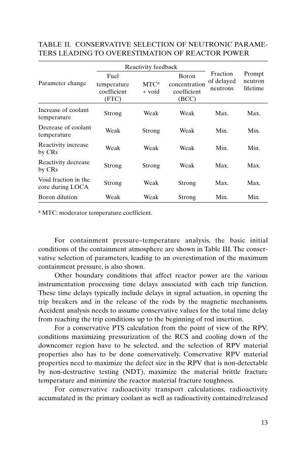
The results of an analysis depend also on the neutronic characteristics ofthe core, which determine the reactor power behaviour during the course ofaccidents.The conservative approach typically aims to overestimate the reactorthermal power, which is strongly dependent on reactivity feedback coefficientsand on the change of core parameters. Reactivity feedback depends on thedirection of the change (increase or decrease) of the parameter under consid-eration. The direction may change during the course of the accident, andtherefore the influence of feedback coefficients may also vary during theprocess.
A conservative selection of the reactivity feedback coefficients for atypical change of parameters is shown in Table II. For more complicated
11

processes it is suggested that parametric analyses to evaluate the influence ofthe coefficients be performed. In selecting the coefficients, there should be,however, no intermixing of values belonging to different operational states(beginning of fuel cycle (BOC); end of fuel cycle (EOC)).
In Table II, ‘weak’ means minimum absolute value of a feedbackcoefficient and ‘strong’ means maximum absolute value of a feedbackcoefficient. Table II is only illustrative. The selected parameters need to bechecked carefully for their influence on the results of the analysis, case by casebefore each application.
A significant influence on reactor power comes also from theassumptions associated with scram reactivity. The negative reactivity insertionfollowing a reactor trip is a time function of the rod position itself and of thevariation in rod worth with position in the core. For accident analysis, the keyparameter is typically the time of insertion up to ‘dashpot entry’ (around 85%of CR assembly travel). The selected value needs to be conservatively higherthan the measured values for any of the fuel loadings. Conservative values alsohave to be selected for the integral value for scram reactivity.
12
TABLE I. TYPICAL INITIAL CONDITIONS FOR PLANT ACCIDENTANALYSIS
ParameterConservative direction
Core cooling System pressure
Reactor power Max. Max.Reactor residual heat Max. Max.Reactor coolant flow Min. Min.Reactor core bypass Max. Min.Reactor coolant temperature Max. Min.Reactor coolant pressure Min.a Max.Steam generator level Min. Min.Steam pressure Max. Max.Feedwater flow N/A (consistent N/A (consistent
with power) with power)Pressurizer level Min. Max.Power peaking factor Max. Max.CR worth available for reactor scram Min. Min.
a For LOCA analysis, a maximum value should be selected. For ATWS and SA analysis,best estimate plant initial conditions are typically acceptable, even for design and licens-ing type analyses.
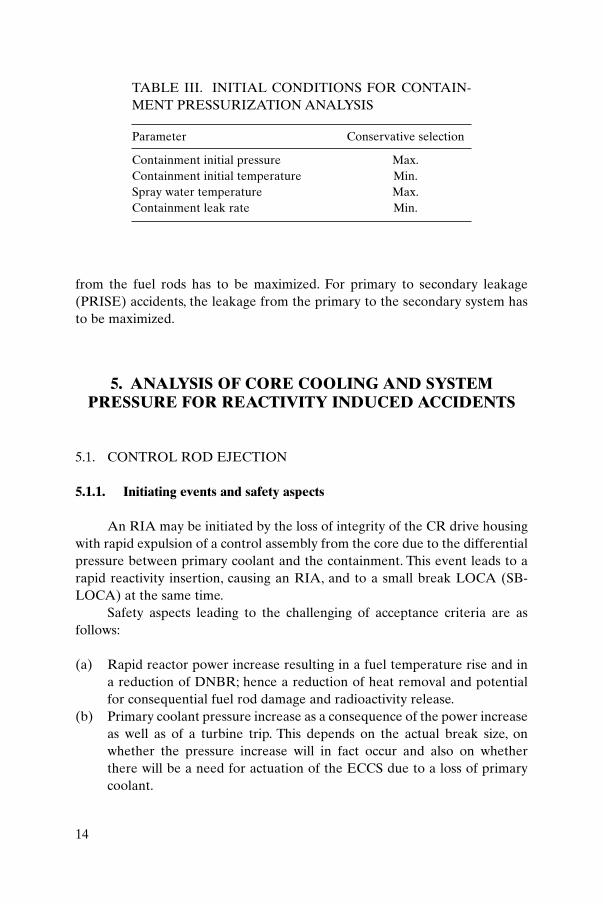
For containment pressure–temperature analysis, the basic initialconditions of the containment atmosphere are shown in Table III. The conser-vative selection of parameters, leading to an overestimation of the maximumcontainment pressure, is also shown.
Other boundary conditions that affect reactor power are the variousinstrumentation processing time delays associated with each trip function.These time delays typically include delays in signal actuation, in opening thetrip breakers and in the release of the rods by the magnetic mechanisms.Accident analysis needs to assume conservative values for the total time delayfrom reaching the trip conditions up to the beginning of rod insertion.
For a conservative PTS calculation from the point of view of the RPV,conditions maximizing pressurization of the RCS and cooling down of thedowncomer region have to be selected, and the selection of RPV materialproperties also has to be done conservatively. Conservative RPV materialproperties need to maximize the defect size in the RPV that is non-detectableby non-destructive testing (NDT), maximize the material brittle fracturetemperature and minimize the reactor material fracture toughness.
For conservative radioactivity transport calculations, radioactivityaccumulated in the primary coolant as well as radioactivity contained/released
13
TABLE II. CONSERVATIVE SELECTION OF NEUTRONIC PARAME-TERS LEADING TO OVERESTIMATION OF REACTOR POWER
Parameter change
Reactivity feedbackFraction Prompt
of delayed neutron Fuel Boron
neutrons lifetimetemperature MTCa concentration coefficient + void coefficient
(FTC) (BCC)
Increase of coolant temperature
Strong Weak Weak Max. Max.
Decrease of coolant temperature
Weak Strong Weak Min. Min.
Reactivity increase by CRs
Weak Weak Weak Min. Min.
Reactivity decrease by CRs
Strong Strong Weak Max. Max.
Void fraction in the core during LOCA
Strong Weak Strong Max. Max.
Boron dilution Weak Weak Strong Min. Min.
a MTC: moderator temperature coefficient.
from the fuel rods has to be maximized. For primary to secondary leakage(PRISE) accidents, the leakage from the primary to the secondary system hasto be maximized.
5. ANALYSIS OF CORE COOLING AND SYSTEMPRESSURE FOR REACTIVITY INDUCED ACCIDENTS
5.1. CONTROL ROD EJECTION
5.1.1. Initiating events and safety aspects
An RIA may be initiated by the loss of integrity of the CR drive housingwith rapid expulsion of a control assembly from the core due to the differentialpressure between primary coolant and the containment. This event leads to arapid reactivity insertion, causing an RIA, and to a small break LOCA (SB-LOCA) at the same time.
Safety aspects leading to the challenging of acceptance criteria are asfollows:
(a) Rapid reactor power increase resulting in a fuel temperature rise and ina reduction of DNBR; hence a reduction of heat removal and potentialfor consequential fuel rod damage and radioactivity release.
(b) Primary coolant pressure increase as a consequence of the power increaseas well as of a turbine trip. This depends on the actual break size, onwhether the pressure increase will in fact occur and also on whether there will be a need for actuation of the ECCS due to a loss of primarycoolant.
14
TABLE III. INITIAL CONDITIONS FOR CONTAIN-MENT PRESSURIZATION ANALYSIS
Parameter Conservative selection
Containment initial pressure Max.Containment initial temperature Min.Spray water temperature Max.Containment leak rate Min.
(c) Containment pressure and differential pressures increase, leading to pres-sure loading of the containment walls; owing to the smaller break size, thisaspect is usually much less important.
(d) Radiological consequences due to a loss of primary coolant, potentiallyalso due to a loss of cladding integrity or fuel disintegration.
The suggestions provided in the following are relevant for the first safetyaspect mentioned above; other aspects need to be considered separately(Sections 10, 16 and 17). Relevant acceptance criteria are Nos (4)–(8) inSection 3.
5.1.2. Specific suggestions for analysis
Several cases need to be considered in the analysis. These include BOCand EOC, hot full power (HFP) and hot zero power (HZP), as well as inter-mediate power levels. The BOC case is the minimum feedback case since ittypically has the least negative moderator temperature coefficient (MTC). TheEOC case has a slightly smaller Doppler coefficient but a much largermoderator feedback effect. This causes the EOC transient to be less severethan the BOC transient for the same reactivity excursion (measured in USdollars). However, for EOC the reactivity in US dollars may be larger due tothe reduction of the fraction of delayed neutrons with increasing core lifetime.Both these cases therefore have to be analysed to sufficiently cover the rangeof expected conditions. Sometimes intermediate stages between BOC andEOC have also to be considered to ensure conservatism of results.
For the purpose of the analysis, the accident may be simulated by linearlyintroducing reactivity up to the ejected rod worth within a sufficiently shorttime span (e.g. 0.1 s). This linear reactivity addition is a calculation conveniencerather than an attempt to simulate the actual ejection of a rod. Such anassumption is acceptable since the 0.1 s ejection time is rapid enough comparedwith the non-linear feedback effects, so that the calculation is not sensitive tothe expected S shape of the reactivity versus distance curve.
The value of the reactivity to be inserted during the accident is to befound by means of three dimensional (3-D) steady state neutronics calculationsthat incorporate all possible reactor states and all possible CR positionsallowed by the operational limits and conditions of the NPP.
It is also preferable that a transient 3-D neutronic analysis be performed.Optionally, a combination of a 3-D steady state power distribution analysis witha transient point kinetics calculation of the total reactor power is acceptable.For the latter case, the steady state power distribution has to be calculated atleast for two operational states: for the initial reactor state before the accident
15

and for the state after CR ejection (at the same power level). For the transientanalysis with a fixed power distribution, the distribution with a higher peakingfactor needs to be chosen. The neutron flux power peaking factor canoptionally be linearly increased from its initial steady state value to the finalvalue within the time for the rod to be ejected.
Core inlet coolant temperature, core flow and coolant pressure may be keptconstant for the analysis of the reactor power increase due to the fact that changesof these parameters are not substantial during the short time interval analysed.
Conservative values of reactor trip reactivity (conservative time delayand reactivity versus CR position dependence) are used, typically assuming astuck CR in addition to the ejected rod. The stuck rod selected is the highestworth rod at HZP with all rods inserted except the ejected rod, and will usuallybe a rod adjacent to the ejected rod.This assumption is made to account for thepossibility of the ejected rod causing damage to an adjacent rod drive housingand preventing that rod from tripping.
A weighting factor is applied to the calculated Doppler feedback toaccount for the expected increase in feedback as a result of the skewed powerdistribution after the CR has been ejected. The Doppler weighting has to beconservatively calculated.
In applying the single failure criterion, considering that the first signal toactuate the reactor trip system has to come from an excessive increase rate ofthe neutron flux, a potential failure in a reactor power measurement channelalso needs to be taken into consideration.
5.2. CONTROL ROD WITHDRAWAL
5.2.1. Initiating events and safety aspects
For analysis of CR withdrawal, the uncontrolled withdrawal of a bank ofCRs either at subcritical/zero power conditions or at full power is considered.The accident is caused either by a control system failure or by an erroneousoperator action.
Control rod withdrawal results in a power excursion accident with areduction in DNBR. The core thermal limit, i.e. the DNB, can be exceeded. Thepower excursion is limited by temperature feedback effects and/or by reactortrip. The excursion also leads to an increase in both the primary and thesecondary system pressure. Owing to the fact that CRs are withdrawn at thenormal operational velocity, the reactivity insertion rate, and consequentlythe power excursion, is significantly slower than in the rod ejection case.
Relevant acceptance criteria are Nos (1)–(3) in Section 3.
16
5.2.2. Specific suggestions for analysis
Both zero power and full power conditions have to be considered toverify the effectiveness of feedback effects and the reactor trip system inlimiting the power excursion. Other initial conditions will be selected similarly,as for the CR ejection accident.
The maximum reactivity insertion rate may be calculated by a 1-D or a 3-D code. Other conditions are the same as for a CR ejection accident. For aconservative calculation, conservative values of the time when reactor tripoccurs (from which parameter the reactor scram is activated) and of thereactivity of withdrawn CRs have to be used.
Selection of a single failure criterion needs to be made depending on theacceptance criterion considered. For example, a failure in the pressurizer reliefvalve, which is conservative for the primary system pressurization, is notnecessarily conservative from the point of view of minimum DNBR.
5.3. CONTROL ROD MALFUNCTION
5.3.1. Initiating events and safety aspects
Three possible events are typically considered in this group:
— Drop of one CR,— Withdrawal of one CR,— Misalignment of one CR.
As a consequence of any of these events, there is a distortion in the corepower distribution with potential reduction of DNBR. For a CR withdrawal,there is also a global reactor power increase, which is reduced later by thereactor power control.
A potentially relevant safety aspect comes from the case when a roddrops into the core and the CR system is in automatic mode. In this case, therods will be moved out to compensate for the sudden power decrease. Beforeachieving a new equilibrium power, a transient overshoot on nuclear power canbe expected, coincident with a significant distortion in radial power distributioncaused by the dropped rod. High local peaking factors together with anovershoot in power may violate the limits on fuel power density.
Applicable criteria for these events are Nos (1)–(3) in Section 3, sincethose cases are categorized as AOOs. Optionally, a withdrawal of one CR canbe also categorized as an accident, with relevant acceptance criteria to be used.
17
5.3.2. Specific suggestions for analysis
A dropped CR or withdrawal of one CR has to be analysed as a transientproblem. Misalignment of a CR can be analysed as a steady state problem. Achange in core power distribution during an accident needs to be adequatelydealt with (see Section 5.1.2 for the case of ejection of one CR).
For the dropped rod case, a sensitivity study has to be performed tosearch for different possible combinations of rods that drop and various singlefailures in reactor trip actuation. A 3-D neutronic calculation has to beperformed to estimate the effect on the ex-core neutron detectors used toactuate the reactor trip system, or a conservative approach needs to considerthe case in which no reactor trip is directly caused by the rate of change inneutron flux. These cases will maximize the combined effect of local fluxdistortion and total nuclear power. Additionally, for transient cases with thecontrol system in automatic mode, adequate modelling of such a system has tobe considered.
Loss of off-site power is usually not considered in combination with thisinitiating event.
5.4. INCORRECT CONNECTION OF AN INACTIVE REACTOR COOLANT SYSTEM LOOP
5.4.1. Initiating events and safety aspects
Such an event is typical, although not exclusively, of WWER-440 reactorswith an MIV installed in both the hot and cold legs of all circulation loops. Thereactor, in accordance with operational limits and conditions, may be inoperation at reduced power, with one of the loops isolated by an MIV. Coolanttemperature and boron concentration can be reduced in the isolated loop. Thereduced values are limited by the plant operational limits and conditions.
The event may be initiated by:
— Startup of the main circulation pump (MCP) in an isolated loop, followedby opening of MIVs;
— Startup of the MCPs in an inoperable non-isolated loop, either notequipped with an MIV or with the MIV remaining in the open position;
— Inadvertent opening of an MIV.
Both causes result from an erroneous operator action. The accident isdeveloping into an RIA due to feedback through the MTC, either due to lower
18

core inlet temperature or due to higher core mass flow rate. Consequently,reactivity insertion leads to a power excursion and a reduction in DNBR.
The event is classified as an accident and therefore acceptance criteriaNos (4)–(7) apply, although a DNB (applicable for an AOO) can usually beavoided. Criterion No. (7) (maximum primary pressure) is not challenged inthis case.
5.4.2. Specific suggestions for analysis
The course of the accident is mostly influenced by the MTC. For conser-vative evaluation, the highest possible negative value of the MTC has to beselected, which is typical for the EOC.At the same time, weak fuel temperaturefeedback needs to be considered. The high power peaking factor is another keyparameter for the analysis.
As the accident may lead to an asymmetry in the core power distribution,coolant mixing in the lower reactor plenum needs to be based either onexperiments or on operational data. Low coolant mixing in the downcomer andin the lower plenum is a conservative assumption. Adequate consideration oftiming for the MIV opening and MCP startup has to be made in connectionwith mixing and the time development of the process. If mixing is not provento be sufficient at the core inlet, the 3-D core neutron kinetics model and the3-D thermohydraulic model are suggested for the analysis.
Selection of initial parameters, such as reactor power, coolanttemperature, number of operating loops and boron concentration in theisolated loop, has to be made in accordance with plant operational limits andconditions.
It is acceptable not to consider loss of off-site power for the analysis. Asingle failure needs to be typically considered in the systems influencing thecore power limitation.
5.5. BORON DILUTION
Boron dilution events are featured by an inadvertent decrease of theboron concentration in the primary coolant.
Homogeneous dilution may occur due to CVCS malfunction whenoperation of primary pumps or natural circulation of coolant is sufficient foruniform mixing in the whole primary circuit. The process is slow and theoperator usually has enough time to take corrective measures. Homogeneousdilution is usually classified as an AOO.
19

Inhomogeneous or local boron dilution takes place if a slug of non-borated water or water with low boron concentration is formed in the primaryloop.There is a potential for rapid core power increase if the slug is transportedwithout sufficient mixing to the reactor core, due to pump startup or forexample to re-establishment of natural circulation.The slug could be formed bynon-borated water injection by the CVCS to stagnant loops or due to leakagesinto the primary system from other systems. These sequences are calledexternal dilution cases and they are classified as accidents.
During accidents with decreased reactor coolant inventory, such as SB-LOCA, PRISE and ATWS, there is a possibility for an inherent dilution whenthe reactor enters into boiling–condensing mode. During this mode, the steamproduced in the core condenses in the SGs and the non-borated condensedwater is collected in the loop seal, forming a diluted water slug. Inherentdilution is one of the safety aspects to be analysed during the correspondingaccidents. These aspects are further discussed in Section 13.
5.6. INADVERTENT LOADING OF A FUEL ASSEMBLY INTO ANIMPROPER POSITION
5.6.1. Initiating events and safety aspects
Such a situation may be caused by inadvertent loading of one or morefresh fuel assemblies into an improper position or incorrect assembly rotationin the core due to human error during the core reloading procedure. The corepower distribution can be consequently distorted, leading to high powerpeaking factors with potential violation of the core thermal limits, which meansa DNBR.
The event is classified as an accident and acceptance criteria Nos (4)–(7)should apply. Criterion No. (7) (high primary pressure) is not particularlychallenged.
5.6.2. Specific suggestions for analysis
The analysis needs to be performed for BOC conditions, corresponding tothe HFP state of the reactor. A combination with other failures is not relevant.Representative combinations of core loading mistakes have to be considered,including wrong positioning of fresh and partially burned fuel assemblies withdifferent burnups.
Owing to the nature of the event, a steady state calculation is adequatefor the analysis. The analysis should prove that either distortion of the core
20

power distribution is detected by the in-core instrumentation or that thechange of the reactor power distribution is acceptable for long term reactoroperation (i.e. it is within acceptable values for power peaking factors).
6. ANALYSIS OF CORE COOLING AND SYSTEM PRESSURE FOR A
DECREASE OF REACTOR COOLANT FLOW
6.1. SINGLE OR MULTIPLE MCP TRIP
6.1.1. Initiating events and safety aspects
An MCP trip due to an interruption of the power supply or failure of thecontrol system is the most typical cause for a reduction of primary coolant flow.Reduction of the primary flow leads to an imbalance between the heatproduced by the fuel and the heat removed from the core, potentiallyexceeding core thermal limits, which means a DNBR. Thermal imbalance alsoleads to an overall pressure–temperature transient, typically resulting in a shortterm pressurization of both the primary and the secondary circuit.
MCP trips are typically categorized as anticipated operationaloccurrences, therefore acceptance criteria Nos (1)–(3) of Section 3 apply.
6.1.2. Specific suggestions for analysis
The flow distribution between the core flow and the bypass flow needs tobe conservatively considered. Selection of an adequate DNBR correlation isessential. A statistical analysis (validation combined with a definition ofuncertainty against experimental data) is required.
Three dimensional effects of coolant mixing in the reactor downcomerand the RPV lower plenum are required to be taken into account or conser-vative assumptions have to be adopted, except for the case when all the MCPsare tripped simultaneously. For an analysis of individual pump trips, fourquadrant pump characteristic curves are needed. A combination of the eventwith loss of power supply is not required.
The single failure criterion typically considers a failure to open either asecondary steam bypass station or the pressurizer relief valves.
21
For reactors equipped with a special power control system designed tocope with MCP trips, consideration of this control system is acceptable.Optionally, a failure of this system might be analysed.
6.2. INADVERTENT CLOSURE OF A MAIN ISOLATION VALVE IN AREACTOR COOLANT SYSTEM LOOP
6.2.1. Initiating events and safety aspects
Such an event is possible for reactor designs with MIVs (gate valves)installed in circulating loops.The MIV closure time is typically several tenths ofa second, resulting in a relatively slow reduction of the core flow. The event canbe initiated by an erroneous manual operator action. Safety aspects andapplicable criteria are the same as in the case of an MCP trip.
6.2.2. Specific suggestions for analysis
Events can be modelled by introducing an input function for thehydraulic resistance of the MIV in the corresponding primary loop. Othersuggestions are the same as for MCP trips (Section 6.1.2).
6.3. SEIZURE OF ONE MAIN CIRCULATION PUMP OR SHAFT BREAK OF ONE MAIN CIRCULATION PUMP
6.3.1. Initiating events and safety aspects
The cause of such an event can be mechanical damage. The event itselfleads to a very sharp reduction of the flow in the corresponding loop, typicallywithin a time shorter than 1 s. In the case of MCP seizure, it is assumed that thesupport components are designed to withstand transient mechanical loadswithout the failure of primary piping.
The event is categorized as an accident, and therefore acceptance criteriaNos (4)–(8) apply.
6.3.2. Specific suggestions for analysis
The same additional suggestions are valid as provided for MCP trips(Section 6.1.2).
22
6.4. COOLANT FLOW BLOCKAGE IN A FUEL ASSEMBLY
6.4.1. Initiating events and safety aspects
Such an event is typically caused by the presence of debris in the primarycircuit following a refuelling/maintenance period. They lead to total or partialcoolant flow reduction and sudden disproportion between heat generation inthe fuel assembly and heat removal from the fuel assembly. Owing to thesefacts the local coolant temperature increases, the cladding temperature alsoincreases and, consequently, the DNBR decreases.This two phase flow typicallytakes place in the fuel assembly. However, the impact on the overall plantbehaviour can still be insignificant.
The event is categorized as an accident, and therefore acceptance criteriaNos (4)–(8) apply.
6.4.2. Specific suggestions for analysis
A subchannel or 3-D thermohydraulic computer code is required for thisanalysis. Parameters in the lower plenum and the upper plenum of the reactorcan be specified as boundary conditions for detailed core analysis.
7. ANALYSIS OF SYSTEM PRESSURE FOR INCREASE OF REACTOR COOLANT INVENTORY
7.1. INADVERTENT ACTUATION OF THE EMERGENCY CORECOOLING SYSTEM
7.1.1. Initiating events and safety aspects
Such an event can be initiated either by control system malfunction or byoperator error, often during testing of the ECCS.
The safety aspects of the event are as follows:
(a) There is a pressurization of the primary system due to an increase of thecoolant inventory.
(b) Emergency injection of cold coolant may lead to non-symmetrical reduc-tion of the coolant temperature at the RPV inlet, potentially affectingvessel integrity.
23
(c) In the case of overfilling of the pressurizer, the accident could lead to thepressurizer safety valve becoming stuck in the open position and a LOCAdeveloping.
(d) In the case of loss of integrity of the pressurizer relief tank, containmentpressurization will take place.
For aspect (a), which is mainly considered in this section, the applicableacceptance criterion is No. (2) (Section 3). Aspect (b) needs to be analysed bythe methodology for PTS (Section 14). Aspect (c) has to be analysed inaccordance with Section 10 and aspect (d) in accordance with Section 16.
7.1.2. Specific suggestions for analysis
Application of a single failure criterion has to take a failure in thepressurizer relief (safety) valves into consideration. The integrity of thepressurizer relief tank also needs to be analysed. Such events are typically notcombined with a loss of off-site power.The maximum capacity of the ECCS hasto be used as a conservative assumption in the analysis.
7.2. MALFUNCTIONS IN THE CHEMICAL AND VOLUMECONTROL SYSTEMS
7.2.1. Initiating events and safety aspects
The event may be initiated by a failure in the control system of the CVCS,which leads to an increase of the reactor coolant inventory. Safety aspects arethe same as for the startup of the ECCS. Moreover, there is a potential forinjecting non-borated water, which would cause an RIA (Sections 5 and 13).For other aspects, the relevant acceptance criterion is No. (2) in Section 3.
7.2.2. Specific suggestions for analysis
The same suggestions as provided for the actuation of the ECCS apply(Section 7.1.2).
24
8. ANALYSIS OF CORE COOLING AND SYSTEM PRESSURE FOR INCREASE OF
HEAT REMOVAL BY THE SECONDARY SIDE
8.1. STEAM LINE BREAKS
8.1.1. Initiating events and safety aspects
Such accidents can be initiated by a partial or full steam line rupture,which may occur either inside or outside the containment. The limiting size fora break (typically located outside the containment) is rupture of the mainsteam header (if relevant) up to its full size break.
The accident leads simultaneously to depressurization (cooling down) ofthe secondary circuit and loss of the secondary coolant, leading also toovercooling of the RCS.Typically, the effect of cooling down dominates, leadingto a non-symmetrical cooling of the RPV wall, to a positive reactivity insertion,to a potential recriticality and to a reactor power increase in some situationsregardless of scram.
Safety aspects of this accident, with possible violation of acceptancecriteria, are as follows:
(a) Possible reactor power increase or reactor recriticality after its shutdowndue to a substantial decrease of the core inlet temperature, typically inone section of the core adjacent to the affected loop. In the case of a coin-cident loss of power supply (MCP coastdown), the DNBR is reduced anda boiling crisis can occur in the reactor core.
(b) Loss of secondary coolant due to steam outflow; this is usually less signif-icant than the cooling effect of depressurization.
(c) Significant and rapid non-symmetrical reduction of coolant temperatureat the RPV inlet followed by high pressure emergency coolant injection,potentially affecting the vessel integrity.
(d) Containment pressure and sub-compartment differential pressureincrease, leading to pressure loading of the containment structure (in thecase of a break inside the containment).
(e) Containment temperature loading (usually higher than during primarycircuit LOCAs).
(f) Loss of secondary coolant can lead to SG tube bundle uncovery, primarycircuit temperature increase and high pressure injection system (HPIS)activation. This situation can lead to an increase of primary pressure, fill-ing of the pressurizer and overpressurization of the primary circuit.
25

Aspects (b)–(e) above have to be analysed by a special methodology(Sections 9, 14 and 16). Therefore, the rest of this section is applicable only toaspects (a) and (f). Such events belong to the category of accidents, andtherefore acceptance criteria Nos (4)–(8) in Section 3 apply. For some designsit is, however, possible to comply even with the more stringent criteria,Nos (1)–(3), for this type of accident.
8.1.2. Specific suggestions for analysis
Typically, the analysis needs to be performed for both HFP and HZPoperational states, with and without MCPs running. Reactivity feedback coeffi-cients (in absolute values) are to be selected for the EOC with the aim ofmaximizing the possibility of returning to criticality.
The break location and flow model for steam release have to be selectedin such a way that the break outflow is maximized. Consideration of the flowmeasuring nozzles and valves installed in the steam lines is, however, importantfor the calculation of the break outflow. The most severe case for a steam linebreak is typically a break upstream of the main steam isolation valve (MSIV).Breaks downstream of the MSIV will be stopped when the valve closes (if notdamaged).
It should be considered that at the reactor trip the most effective CR wasstuck in its upper position. It has to be assumed that the stuck rod is located inthe cold section of the reactor core adjacent to the affected loop.
The influence of HPIS needs to be analysed parametrically with respect tothe cooldown rate and the change in primary circuit boron concentration.Different numbers of ECCS pumps, pump characteristics and possible non-uniform injection into individual main coolant loops have to be considered in thisanalysis.
In the case of a recriticality, in particular when a point kinetics model isused, maximum power peaking factors possibly occurring during the wholeprocess have to be considered for the DNBR calculations. Xenon decay afterreactor scram may be neglected for processes with durations of severalminutes. Boron addition is allowed to be considered during the accident, but itstime delay needs to be considered conservatively high and its mixing has to beconsidered conservatively low.
DNBR calculations should be performed by a subchannel approach. Forsimplicity, steady state calculations are acceptable at time points chosen conser-vatively along the transient.
Specific requirements for the computer code to be used are as follows:
26

(a) A complex computer code capable of adequately simulating the behav-iour of both the primary and secondary systems as well as neutron kine-tics is needed.
(b) A 3-D dynamic neutronics model is preferred. If this is not available, it isnecessary to combine a conservative 3-D steady state neutronics modelwith a 1-D thermohydraulics model for integral calculations.
(c) A model of non-ideal coolant mixing in the reactor plenum is preferred.If such a model is not available, conservative assumptions on coolant mix-ing need to be used.
(d) The code used has to be able to consider water carry-over by steam flow-ing out of the secondary circuit; otherwise, a conservative approach is tobe chosen to maximize the loss of secondary coolant, also considering,however, the next requirement.
(e) The SG secondary side mixture level has either to be calculated by thebest estimate approach, or a conservative approach needs to be taken tomaximize the cooldown rate.
For the single failure criterion, the following failures are typicallyconsidered:
— CR stuck in the upper position;— Failure of one of the steam leak isolating valves.
The failure of one of the steam leak isolating valves, however, may also occuras a dependent consequential failure due to forces induced by the steam linebreak.
8.2. INADVERTENT OPENING OF STEAM RELIEF VALVES
8.2.1. Initiating events and safety aspects
Such an event can be initiated by a control system failure, by an instru-mentation failure (e.g. sensor failure) or by an operator error, leading toinadvertent opening of or failure to close the valves, and a subsequent releaseof steam from the secondary circuit (SG safety valves, steam dump to theatmosphere or steam bypass to the condenser).
The safety aspects of the event are similar to those for the steam linebreak, except for the containment pressurization. In addition, owing to consid-erably lower steam outflow, the change of all the parameters is slower. The
27
event is categorized as an AOO, therefore acceptance criteria Nos (1)–(3)(Section 3) apply.
8.2.2. Specific suggestions for analysis
The suggestions made in Section 8.1.2 are generally valid for these eventsas well, but less stringent requirements on the computer code may apply.Typically, the 1-D neutronics model, ideal coolant mixing in the reactorplenums, no special model for water-carry over by steam outflow and a conser-vative approach for the SG mixture level model are acceptable.
8.3. SECONDARY PRESSURE CONTROL MALFUNCTION WITH ANINCREASE OF STEAM FLOW RATE
Such events are initiated by a secondary pressure controller malfunction.Safety aspects, acceptance criteria and specific suggestions for analysis are thesame as provided for inadvertent opening of the steam relief valves (Section8.2).
8.4. FEEDWATER SYSTEM MALFUNCTION
8.4.1. Initiating events and safety aspects
Two types of event are considered:
— Malfunctions that increase feedwater flow (a failure of a feedwatercontrol valve);
— Malfunctions that decrease feedwater temperature (a failure of afeedwater preheater).
Both events lead to an increase of heat removal by the secondary side,thus reducing primary coolant temperature and increasing the reactor powerdue to reactivity feedback. Reduction of the DNBR is the main issue, andacceptance criterion No. 1 (Section 3) applies.
8.4.2. Specific suggestions for analysis
The analysis needs to be performed for both HFP and HZP. The event istypically not combined with a loss of off-site power.
28

9. ANALYSIS OF CORE COOLING AND SYSTEM PRESSURE FOR DECREASE OF
HEAT REMOVAL BY THE SECONDARY SIDE
9.1. FEEDWATER LINE BREAK
9.1.1. Initiating events and safety aspects
Feedwater line breaks are typically caused by a material degradation ofthe secondary circuit piping, leading to a partial or full rupture of a pipe in thefeedwater system. Corresponding to the break location, the feedwater supplycan be interrupted in one or several SGs. In the case of a main feedwaterheader rupture, the feedwater supply will be interrupted in all SGs.
The accident differs from steam line breaks due to the fact that the wateroutflow leads to a rapid decrease of the affected SG secondary side water level.Thus, the secondary side heat removal capability is reduced, while cooling, dueto energy outflow, is not so high.
Safety aspects that challenge the acceptance criteria are as follows:
(a) Reduction or loss of secondary side heat removal leads to overheating ofthe primary coolant, with its corresponding expansion and pressurizationof the primary circuit.
(b) For the longer term, heat removal from the core may also be threatened,leading to fuel rod overheating.
(c) In the case of a long term loss of secondary side heat removal, the pres-surizer relief or safety valves may stay opened. The consequences wouldbe similar to those for the corresponding (in size) primary circuit rupture,a LOCA, resulting in the release of radioactivity into the containment.
(d) Outflow of the secondary coolant, and possibly also the primary coolant,leads to containment pressurization.
(e) Injection of cold water on previously uncovered SG tubes by recoveredfeedwater pumps may threaten the structural integrity of the boundarybetween the primary and secondary circuits.
This section deals only with the first two aspects of the accident; otheraspects are partially dealt with in Sections 10, 16 and 17. The event belongs tothe category of DBAs, therefore acceptance criteria Nos (4)–(8) (Section 3)apply.
29
9.1.2. Specific suggestions for analysis
The position of the break has to be selected so as to maximize the loss ofsecondary coolant. The secondary coolant outflow model has to maximize thebreak flow. The accident is typically analysed for both cases, with and withoutloss of external power supply. The single failure criterion is typically applied toemergency feedwater pumps and pressurizer relief or safety valves.
9.2. FEEDWATER PUMP TRIP
9.2.1. Initiating events and safety aspects
Feedwater pump trip, typically due to an interruption in electric powersupply, leads to loss of secondary coolant inventory and, consequently, to areduction of secondary side heat removal. Owing to the imbalance betweenheat production and its removal by the SG secondary side, the temperatureand consequently also the pressure increase in both the primary and thesecondary circuits. These are the dominant effects for such events. The marginto the limiting value of the DNBR will also be reduced due to the temperaturerise of the reactor coolant and, for some events, also due to primary coolantflow reduction, although a bulk boiling crisis is typically not expected in thecore.
Auxiliary and/or emergency feedwater pumps are used to supply water tothe SG after the normal feedwater pump trip.
The event is categorized as an AOO; acceptance criteria Nos (1)–(3)(Section 3) apply.
9.2.2. Specific suggestions for analysis
Loss of off-site power is usually not considered for this type of event.Conservative conditions for reactivity feedback typically occur at the BOC.
Depending on the selected acceptance criterion (short term or long termcooling objectives), application of a single failure criterion needs to take intoaccount potential failures in auxiliary feedwater pumps, pressurizer relief orsafety valves, SG safety valves and steam dump stations.
30
9.3. REDUCTION OF STEAM FLOW FROM STEAM GENERATORFOR VARIOUS REASONS
9.3.1. Initiating events and safety aspects
Reduction of the secondary side heat removal capability can also becaused by an increase of the SG secondary side pressure and temperature as aconsequence of steam flow reduction. The steam flow reduction and/or loss ofa heat sink may be caused by one of the following events:
— Reduction of the steam flow extracted from the SGs due to controlsystem malfunction;
— MSIV closure;— Turbine trip, with corresponding admission valve closure, due to many
different possible failures;— Loss of external electrical load;— Loss of condenser vacuum.
The safety aspects of these events are similar to those for a feedwaterpump trip. All these events are categorized as AOOs and acceptance criteriaNos (1)–(3) apply.
Typically, a simultaneous complete loss of electric supply to the MCPs ispostulated, creating additional concern about the achieved minimum DNBR inthe reactor core during the transient.
9.3.2. Specific suggestions for analysis
All the suggestions made in Section 9.2.2 are also valid for these events.
10. ANALYSIS OF CORE COOLING FOR LOCAs
10.1. INITIATING EVENTS AND SAFETY ASPECTS
A LOCA is caused by loss of integrity of the primary circuit or itsassociated pipes and devices. The direct cause of such an accident is a materialdefect, material fatigue, an external impact (internal missiles or heavy loads) ora device failure during the operation of the plant. Inadvertent opening of thepressurizer valves or any other isolation valve on the primary system boundary
31

can also be analysed as a LOCA. The spectrum of postulated leakage sizeswithin the reactor coolant pressure boundary has been divided in various waysdepending on the selection of the acceptance criteria. In this report, thesubdivision is made into two groups, namely large break LOCAs (LB-LOCAs)and small break LOCAs (SB-LOCAs).
LB-LOCAs mainly include a full or partial rupture of the maincirculation line, typically with break areas higher than 25% of the cross-sectionof the main circulation line. Ruptures of the major pipes connected to theprimary circuit, such as the pressurizer surge line or the accumulator dischargelines, can also be considered as LB-LOCAs. In the case of an LB-LOCA, theloss of primary coolant cannot be compensated for by the ECCS prior tosubstantial depressurization and loss of coolant inventory from the primarycircuit.
SB-LOCAs include such breaks, smaller in size in comparison with LB-LOCAs, which cannot, however, be compensated for by the make-up systemand thus require activation of the ECCS.
All LOCA events are classified as accidents.Loss of primary coolant into the secondary circuit, for example due to the
rupture of the SG tubes, requires special consideration and is discussedseparately in Section 11.
LOCAs have various safety aspects leading to potential violation of theacceptance criteria, as follows:
(a) The high velocity stream of the escaping primary coolant generates jetforces and reaction forces (leading to pipe whip) that endanger other sys-tems close to the ruptured pipe and containment internals. Similarly,mechanical damage can be caused by the MCP rotor overspeed inducedby a very high primary coolant flow directed to the break.
(b) Pressure wave propagation in the primary circuit at the very initial stageof the accident leads to pressure differences across the reactor internalswith large forces acting on the internals.
(c) Loss of coolant resulting in core dry-out leads to loss of coolability of thecore in spite of reactor shutdown; fuel rods are heated, claddingmechanical properties are degraded and the integrity of the cladding canbe lost due to internal fission gas overpressure or thermally inducedstresses.
(d) Cladding ballooning and geometrical distortions of the fuel assembliesmay endanger the long term coolability of the reactor core.
(e) At high temperatures, the cladding material reacts with the steam in anexothermic reaction, with hydrogen as a by-product. This reaction repre-sents an additional heat source for the cladding and can cause further
32

degradation of the cladding material due to oxidation, and the potentialfor hydrogen burning or explosions inside the containment.
(f) High energy coolant outflow into the containment leads to pressurizationof the containment.
(g) Containment pressurization together with high radioactivity in the con-tainment atmosphere (due to fuel damage) leads to leakages into theenvironment with potential radiological consequences.
This section deals mainly with safety aspect (c), and partially with aspects(d) and (e).
Aspects (a) and (b) require special methodologies not covered by thisreport.Aspects (f) and partially (g) are dealt with in Sections 16 and 17, respec-tively.
As already emphasized several times, the selection of acceptance criteriaand consequently also the selection of conservative conditions differs consid-erably depending on the safety aspect under consideration. Generally, differentcalculations have to be performed for an analysis of different aspects of theaccident.
The relevant acceptance criteria typically corresponding to the safetyaspects under consideration are Nos (6), (8) and (9–13) (Section 3).
10.2. SPECIFIC SUGGESTIONS FOR ANALYSIS
The break location varies along the primary circuit and the break size hasto be selected to maximize core heat-up; maximum core heat-up is usuallyobtained for a break size smaller than a full size break.
All sources of generated and stored energy in the RCS and in thesecondary side have to be adequately considered, with a realistic timing foreach of the sources. Selection of a conservative power distribution in the coredepends on the break size. For an LB-LOCA the power distribution shape isnot so important and it is mainly the power peaking factor that plays a crucialrole. For an SB-LOCA with core uncovery, the top skewed power distributionis usually conservative, which is typical for EOC. Conservative conditions foran SB-LOCA may be found by parametric calculations taking into accountcore power shape changes and fuel element properties. All metallic structureshave to be adequately modelled to account for the accumulated heat.
Conservatively low characteristics (low efficiency, low capacity and a longdelay before action is taken) need to be used for reactor scram, and for bothhigh and low pressure ECCS pumps. A sensitivity study with respect to thehydraulic resistance of the hydro-accumulator discharge lines needs to be
33
performed to maximize core heat-up. The flow distribution into the parallelcore channels, particularly distribution of the ECCS coolant from the upperplenum into the fuel channels, and the flow intake from both ends of the fuelchannel have to be considered.Three dimensional effects in the RPV, especiallyin the reactor upper plenum and the downcomer, need to be adequatelymodelled; the applicability of 1-D models with an appropriate (preferablyexperimentally based) selection of nodalization and pressure loss coefficients isnot, however, excluded for this purpose.
Attention has to be paid to proper modelling of the MCP characteristicsat a very high flow rate in the affected loop; the pump characteristics for theturbine flow regime are needed.
LOCAs are typically analysed with the assumption of loss of off-sitepower. Consequently, failure of a diesel generator is a typical assumption forthe single failure to minimize safety injection. For LB-LOCAs, the loss of off-site power is usually assumed to be coincident with the break, but for SB-LOCAs parametric studies may be necessary to find the bounding case.
The long term behaviour of LOCAs, such as the loop seal effect (blockingof steam outflow by water plugs in the circulation loops), may causeoverheating of the core: such cases can be analysed with sufficiently detailedmodels.
The tolerance of the core to the residual insulation material and otherdebris in the ECCS water during recirculation needs to be studied. Possibleboron precipitation problems in the reactor during long term boiling also haveto be studied.
Adequate selection of nodalization is crucial for the quality of theanalysis. Therefore, the nodalization needs to be carefully verified andvalidated [3]. Sufficiently detailed nodalization has to be selected particularlyin the vicinity of the break. This should adequately account for removal ofECCS water out of the break (vessel bypass). Consideration has to be given todetailed modelling of dead ends (e.g. the reactor upper head and CR guidetubes), mainly regarding coolant temperature stratification.These ends may actas pressure maintaining components during the accident. For SB-LOCAanalysis, sufficiently detailed nodalization needs to be applied for loop sealsand SGs in order to adequately consider steam binding and primary tosecondary heat transfer, which strongly influence the course of accidents andcore heat-up.
Generally, the analysis for all LOCAs has to show how a plant is broughtinto a safe controlled state, for example into cold shutdown conditions.
34
11. ANALYSIS OF PRIMARY TO SECONDARY SYSTEM LEAKAGE
11.1. INITIATING EVENTS AND SAFETY ASPECTS
Primary to secondary system (PRISE) leakages are caused by a single ormultiple SG tube rupture or, in addition, for WWER designs with horizontalSGs, by an SG collector break or an SG primary collector cover lifting off. Theaccident may be initiated by fatigue failure of the SG tube wall, material defectsproduced during manufacture or, as a special case, as an induced failure fromanother initiating event (e.g. steam line break or injection of cold feedwater onthe hot SG tubes).
Owing to the large number of SG tubes, the probability of SG tuberupture is relatively high.This accident type is therefore normally considered inthe design. The likelihood of a large PRISE leakage due to a collector breakitself was not included in the original design of WWER reactors. However,operating experience and in-service inspections have demonstrated thepotential for large SG leaks for this design.
The safety aspects associated with a PRISE accident are as follows:
— Direct radioactivity release to the environment, bypassing thecontainment via steam dumps and/or via the SG safety valves;
— Reduced core cooling (short and medium term);— PTS of the RPV due to cooldown and subsequent re-pressurization
following break isolation on the primary side (typical for WWER-440s);— Boron dilution and reactivity insertion due to reverse flow (from
secondary to primary side) through the break;— Potential for an SA initiator because of long term loss of ECCS water
inventory.
The main feature of PRISE leakage is containment bypass resulting in adirect radioactivity release to the environment and an irreversible loss ofprimary coolant. The primary water becomes radioactive during reactoroperation due to the activation of corrosion products and the presence offission products. The water in the secondary system may also contain someradioactive material.
Typically, the short term core cooling during PRISE accidents is assuredeven with a minimum design ECCS configuration. However, in the case of lateleak isolation, the ECCS tanks can be completely depleted and long term coreheat-up may occur.
35
The safety aspects associated with PTS, boron dilution and core cooling(LOCAs) are described in other sections (10, 13 and 14) and are therefore notreflected here. Only the radioactivity release and long term loss of ECCS waterare considered in the following text.
PRISE leakages are categorized as accidents. The main acceptancecriterion relevant for these events is No. (8) (Section 3). It is also required thatthe ECCS water resources be sufficient to cope with the accident without earlyendangerment of the core cooling, assuming maximum PRISE leakage and lateoperator interventions.
11.2. SPECIFIC SUGGESTIONS FOR ANALYSIS
The radioactivity release to the environment depends on the followingfactors:
— Quantity of coolant released to the atmosphere;— Primary coolant activity;— Secondary coolant activity;— Spiking of the iodine isotopes and the noble gases;— Degradation of fuel rods due to high temperatures;— Position of the tube rupture in the broken SG and the decontamination
factor;— Initial power level of the plant.
The radiological consequences of PRISE leakages are usually analysed intwo sequential steps:
(1) System analysis using system thermohydraulic codes;(2) Analysis of radiological consequences using the results of the thermo-
hydraulic calculation as boundary conditions.
The process of radioactivity transport is closely related to the two phaseoutflow of the primary coolant. Some computer codes offer the possibility tocalculate the transport of radioisotopes (including radioactive decay) in bothwater and steam phases of the coolant in addition to the two phase flowmodelling. If needed for separation of the processes of radioactivity transportand coolant transport, a conservative approach has to be used (e.g. notconsidering the dilution of the active primary coolant due to ECCS injection orthe mixing of the primary coolant with the secondary coolant in the SGaffected).
36

The maximum primary to secondary side leak and the maximum activityof the primary coolant are conservative assumptions. To assume of the fullconfiguration of the ECCS and the make-up system may lead to a higher lossof coolant. In addition, the loss of off-site power and the application of thesingle failure criterion can make the process more severe as only limited meansare available for mitigation of the accident.
The primary coolant activity used in the analysis needs to be estimatedaccording to plant operational limits and conditions. The spiking effect causedby the increased release of water soluble products from micro-defects in thefuel cladding into the coolant has to be considered in the estimation of thecoolant activity. This effect varies significantly and quite irregularly for thesame reactor.The spiking effect has been noticed most clearly for 131I.A typicalupper estimate for the spiking factor (SF) for iodine isotopes is SF = 100(activity increased by a factor of 100 during transient conditions as opposed tothe iodine activity during a steady state operation). The average value duringthe first half hour is typically SF = 50. The most conservative value for thespiking factor is 500. The spiking of noble gases is comparatively small and hasa completely different time trend. The spiking factor proposed in the literaturefor noble gases is SF = 10, Ref. [10].
The possibility that secondary side SG safety valve(s) or steam dump(s)to the atmosphere are stuck open after their actuation has to be considered, inparticular if these devices are not qualified for two phase flow. Generally, thesystems not qualified for relevant accident conditions need to be considered tofail, particularly if such a failure leads to a worsening of the consequences(especially failure of isolation devices to close).
A single failure in safety systems, for example failure to close one steamdump valve to the atmosphere or an SG safety valve in the affected SG, has tobe considered. However, if the SG safety valves are not qualified for two phaseflow or water flow operation, their failure to close under such conditions shallbe considered. The analysis is to be performed until the final safe condition ofthe plant is reached, for example with the primary pressure below the set pointsof the steam dumps to the atmosphere and the SG safety valves in the case oftheir proper operation, or until the primary system is depressurized toatmospheric pressure.
In the case when the accumulator pressure is higher than the set points ofthe secondary side safety relief valves, the isolation of the accumulators needsto be considered only in the case where this is clearly stated in existingemergency operating procedures.
Operator interventions are essential for the termination of a PRISE leakand mitigation of the radiological consequences. These interventions are to beconsidered after a sufficient time, which is typically 30 min but in any case not
37

shorter than 10 min after the initiating event. It should be demonstrated thatthis time is sufficient for reliable identification of the affected SG by plantoperators.
National limits placed on releases of radioactivity, individual doses andcollective doses shall be used in the analysis.
Final safe conditions of the plant can also be assumed after reachingconditions for operation of the RHR system.
12. ANALYSIS OF ANTICIPATED TRANSIENTS WITHOUT SCRAM
12.1. INITIATING EVENTS AND SAFETY ASPECTS
The initiating event for ATWS is an AOO combined with a reactor scramfailure when required to actuate. It is typically assumed that the scram signalfails or the CRs do not move for mechanical reasons. Typical initiating eventsto be analysed are to be selected from a group of initiating events with higherprobability (except the probability of reactor scram) and may be summarizedas follows:
(a) Failure of main heat sink:— loss of condenser vacuum;— closure of MSIVs;— turbine trip.
(b) Increase of steam flow:— opening of turbine bypass valves;— opening of steam line safety valves.
(c) Loss of main feedwater supply.(d) Loss of alternate circuit (AC) power.(e) Inadvertent CR withdrawal:
— at a particular power level;— at subcritical or low power startup conditions.
(f) Loss of load.
Usually, generic studies are designed to identify which of these initiatingevents are the limiting cases. Very often, loss of the main feedwater gives themost adverse consequences.
38

The safety aspects of these accidents, leading to challenging of acceptancecriteria, are as follows:
(a) Primary coolant temperature rise as a consequence of inadequate heattransfer to the ultimate heat sink;
(b) Primary coolant pressure rise as a consequence of primary coolant expan-sion;
(c) Possible rise of pressurizer water level to the valve nozzles, with ‘solidwater’ being discharged to the pressurizer relief tank;
(d) Fuel cladding temperature rise as a consequence of possible DNB;(e) Formation of a low boron concentration water plug in loop seals as a con-
sequence of a possible primary coolant boiling–condensing cooling modedue to degradation of the primary coolant level below the hot leg eleva-tion;
(f) Radiological consequences due to loss of primary coolant via the pres-surizer safety valves in conjunction with a loss of fuel cladding integrity.
This section deals mainly with the first four aspects of the list above. Theremaining aspects are dealt with separately (Sections 13 and 17). Acceptancecriteria Nos (4)–(8) apply for this type of accident. Of course, these criteriaapply only if ATWS are included among the DBAs. However, ATWS aretypically considered as BDBAs, which are either excluded from the analysis or,if not, a best estimate approach is accepted for the analysis. It is thereforesuggested that detailed conditions for the analysis are agreed upon between theanalyst and the user of the results.
12.2. SPECIFIC SUGGESTIONS FOR ANALYSIS
The level of conservatism for this type of accident is typically subject tospecific national requirements, but usually a best estimate analysis isacceptable. Owing to the very low probability of coincidence of the initiatingevent and a reactor scram failure, it is acceptable to consider that other plantsystems, including the plant control systems, will operate in accordance with thedesign requirements if they are qualified for post-accident conditions. Thisspecifically means that all trains of safety systems can be considered operable,i.e. the single failure criterion may not be adopted. Loss of power is also notconsidered. There are, however, other approaches which assume a similarchoice of calculation parameters and of failures in safety systems as for conser-vative analyses of other accidents [12].
39

It is acceptable to use realistic data for the Doppler reactivity and CReffectiveness if they are derived from experiments or adequately validatedcodes. It is, however, recommended to use reasonably conservative values forother parameters including CR position, fuel temperature, hot channel peakingfactor and local linear heat rate.
As CRs are not considered to stop the generation of fission power, theboron injection system is an essential means for shutting down the reactor (inaddition to coolant boiling). The minimum injection flow of this system needsto be considered. For analysis, transport of boron has to be assumed for theliquid phase only.
If reactor coolant pumps are stopped following the event, naturalcirculation is needed, together with the boron injection system, to transportboron into the reactor and to shut it down. The code used to analyse ATWSevents must be capable of calculating natural circulation under the corre-sponding operating conditions. This includes both one phase and two phasenatural circulation models.
Steam generator modelling has to be such that the heat transfer from theprimary circuit to the secondary circuit is calculated as realistically as possible. This means that when the heat transfer tubes are uncovered as thelevel drops, there is a resultant decrease in the heat transfer rate to thesecondary side.
If the boiling–condensing cooling mode takes place during the accident asa result of excessive loss of coolant inventory, the boron concentrationincreases in the core area. However, during this phase a water plug with verylow boron concentration may be formed in the cold legs, especially for designswith the potential for formation of loop seals. If the water plug for any reasondeparts from the loop, there is a chance that it may enter the core without anymajor mixing during its transport to the core and cause a recriticality of thecore. The diluted slugs formed during the boiling–condensing mode can causelarge reactivity changes. ATWS events should also be analysed taking intoaccount this phenomenon.
Attention has to be paid to an adequate modelling of the pressurizer toaccount for pressurization of the primary circuit, for the possibility ofcompletely filling the pressurizer with water and for water discharge throughthe pressurizer valves.
Preferably a 3-D reactor kinetics calculation capability, and at least a 1-Dcapability, is required in most ATWS event analyses. The capability for hotchannel analysis needs to be available. A detailed nodalization needs to beselected in particular for the core, both the reactor plenums and the SGs onboth the primary and secondary sides.
40
13. ANALYSIS OF BORON DILUTION ACCIDENTS
13.1. INITIATING EVENTS AND SAFETY ASPECTS
Boron dilution events are caused by an inadvertent decrease of the boronconcentration of the primary coolant. The boron dilution process can behomogeneous or inhomogeneous.
Homogeneous dilution may occur due to CVCS maloperation when theprimary pumps or natural circulation are sufficient for uniform mixing of thewhole primary circuit. The process is slow and the operator usually hassufficient time for corrective measures. It is usually classified as an AOO.
Inhomogeneous or local dilution takes place if a slug of non-boratedwater or low boron concentration water is formed in the primary loop. There isa potential for rapid core power increase if the slug can be transported withoutsufficient mixing to the reactor core by pump startup or by re-establishingnatural circulation.The slug could be formed by non-borated water injection ofCVCS into stagnant loops or through leakages from other systems. The processof slug formation could appear during different modes of operation. Thesesequences are called external dilution cases and they are classified as accidents.
During accidents with decreased reactor coolant inventory such as SB-LOCAs, PRISE leaks and ATWS there is a possibility for an inherent dilutionwhen the boiling–condensing cooling mode occurs. During this mode, the steamproduced in the core condenses in the SG and the non-borated condensatecollects in the loop seal, forming a diluted slug.
In SB-LOCA and ATWS events the liquid level in the RPV may decreasebelow the hot leg elevation. As a consequence, steam begins to flow to the SGand condenses there. Because the steam carries practically no boron, the boronconcentration in the cold leg loop seals begins to decrease. If for some reasonthis water plug with low boron concentration begins to flow towards the coreand enters there without any major mixing with the borated coolant, the eventresults in a positive reactivity insertion.
During a PRISE leakage the primary pressure during the accident maydecrease below the affected SG pressure, reversing the break flow. Water witha low boron concentration flows from the affected SG to the primary circuitand further to the core. The situation becomes worse if feedwater isolation hasfailed.
Generally, the course of boron dilution accidents strongly depends on:
— The formation of a slug with reduced boron concentration;
41
— Mixing of the slug with the primary coolant during its transport to thecore;
— Reactor power excursion due to propagation of the slug into the core.
Inadvertent positive reactivity insertion to the core may lead to recriti-cality and a power increase in the core.The course of such an accident is similarto those of other types of reactivity accidents, either slow (i.e. CR withdrawal)or rapid (i.e. CR ejection).While for slow accidents there is typically a sufficienttime margin for a timely isolation of the source of non-borated water from theprimary circuit, for rapid accidents the power increase and its consequences canbe serious, even if reactor scram occurs.
If boron dilution occurs during the course of another initiating event (e.g.a LOCA or ATWS) then the safety aspects of this particular event are alsorelevant.
For accidents with pure water injection from an external source, therelevant acceptance criteria may be as follows:
(a) For inhomogeneous external boron dilution events with the MCP startupaccelerating the slug into the core, the acceptance criterion could be thatno recriticality of the core (after reactor scram) is allowed.
(b) For inherent boron dilution events, where the slug is typically transport-ed by re-establishment of natural circulation, the acceptance criteria haveto be combined with the acceptance criteria of the initial accident con-cerning the fuel heat-up.
13.2. SPECIFIC SUGGESTIONS FOR ANALYSIS
For a conservative analysis, the initial boron concentration and mass flowof injected non-borated water has to be maximized, while the circulatingvolume of primary coolant, as well as the estimated mixing of non-boratedwater with primary coolant, has to be minimized.
For slow processes with sufficiently high flow rates in the primary circuit,a simplified approach with uniform coolant mixing may be used.
For a sudden reactivity insertion the process is very complex and has stillnot been fully investigated. Modelling needs to cover the following aspects ofthe accident:
— Overall system response;
42
— Process of diluted boron mixing in the RPV downcomer and in the lowerplenum, by application of a 3-D thermohydraulic computer code withturbulent mixing;
— 3-D neutron kinetics;— Mechanical response of the fuel.
Various aspects of the accident may be analysed in several separate stepsusing different computer codes.
14. ANALYSIS OF PRESSURIZED THERMAL SHOCKS
14.1. INITIATING EVENTS AND SAFETY ASPECTS
PTS represents one aspect of a variety of accident scenarios, charac-terized by overcooling of the RPV wall (typically non-uniform), occurringunder high pressure in the primary circuit. PTS results in high temperaturegradient induced stresses, threatening the integrity of the RPV wall. Conditionscould be worsened by RPV repressurization. PTS aspects have to beconsidered for all accidents with ECCS cold water injection and for accidentsleading to cooldown of the downcomer, such as rapid depressurization of thesecondary circuit.
Consequently, the following groups of initiating events need to beconsidered:
— LOCAs, especially small and medium breaks;— Stuck open pressurizer safety or relief valves;— PRISE leaks;— Large secondary circuit leaks;— Inadvertent actuation of high pressure injection or make-up systems;— Accidents resulting in cooling down of the RPV from the outside; this
reflects flooding of the reactor cavity, for example by the ECCS or spraysystem.
Rapid cooldown, typically non-uniform, of the RPV wall is caused by acold water plume in the reactor downcomer or by external flooding of the RPV.The conditions are further worsened if the primary circuit pressure is high. TheResulting thermal stresses in the RPV wall may potentially threaten itsintegrity.
43
Other aspects of relevant accident scenarios, such as loss of primary orsecondary coolant inventory or of containment pressurization, are of secondaryimportance from the reactor integrity point of view and they are not consideredhere. The relevant acceptance criterion for PTS is No. (16) (Section 3).
14.2. SPECIFIC SUGGESTIONS FOR ANALYSIS
Owing to the complexity of the PTS, the compliance with criterion No.(16) is typically analysed in the following consecutive steps:
(1) Neutron fluence calculation for the period of the reactor operation;(2) System thermohydraulic calculation;(3) Fluid–fluid mixing calculation;(4) Structural analysis.
This guidance does not deal with the neutron fluence calculation, whichrequires a special methodology, usually not considered as corresponding to theterm ‘accident analysis’. Other steps of the analysis are interrelated as follows:
(a) The system thermohydraulic calculation should provide the followingparameters as a function of time for the RPV wall temperature and stresscalculations:— Downcomer coolant temperature distribution;— Coolant to wall heat transfer coefficients in the downcomer;— Primary circuit pressure.
(b) The objective of the structural analysis is to calculate the temperature andstress fields in the RPV and to evaluate the stress intensity factors for pos-tulated cracks loaded by thermohydraulic transients. The results of theanalysis for the structure are typically as follows:— Temperature distribution;— Stress–strain distribution;— Loading of postulated defects in terms of stress intensity factor.
The sources of uncertainties in the analysis are associated mainly with thefollowing aspects:
— Thermohydraulic transient analysis (prediction of flow stagnation, coldcoolant injection rate, cooldown rate and pressure behaviour);
— Fluid temperature distribution and coolant to wall heat transfercoefficients distribution in the RPV downcomer;
44
— Assumptions of the structural analysis model including boundary (thecoolant temperature distribution) and initial conditions;
— RPV material properties including fracture toughness in initial as well asend of life states;
— Neutron fluence;— Method of calculation of the stress intensity factors;— Crack geometry and size with respect to NDT effectiveness;— Operator action.
Therefore, careful consideration needs to be given to the aspects above andcorresponding sensitivity studies have to be carried out.
In the analysis, attention is to be paid to scenarios leading to flowstagnation, which causes a higher cooldown rate and formation of cold plumesin the downcomer. Reliable prediction of the flow stagnation is verycomplicated but essential for a PTS analysis. Various phenomena influence theonset of flow stagnation, such as coolant discharge, ECCS injection, SG heattransfer and coolant mixing in the downcomer. Nodalization of SGs and of thedowncomer plays an important role in predicting the occurrence of flowstagnation. Typically, earlier prediction of the flow stagnation represents aconservative direction. Particularly for the time period close to the primaryflow stagnation, the existence of downcomer cold plumes, causing thetemperature and heat transfer coefficient distributions to be non-uniform andasymmetric, should be taken into account.
For cases with subcooled water in the whole primary circuit, modelling ofthe discharge flow (selection of the critical flow model and specification of thehydraulic resistance of the discharge tube) may have a significant effect on theresults. For conservative analysis, the ECCS injection flow rate and thesecondary system cooling capacity have to be maximized, while the ECCSwater temperature and thermal mixing of the ECCS water with primarycoolant have to be minimized.
Modelling of the natural circulation is typically validated for the steadystate conditions during normal operation of an NPP. In many cases theconditions during accidents differ significantly from normal operation, and thevalidity of modelling needs to be carefully considered. The same considerationalso applies for the discharge flow through the safety valves, for which theequivalent size is defined for the single phase steam outflow. For complexaccident situations with water and a two phase discharge, the flow also dependson the model of the critical outflow applied.
In PTS analysis, the various aspects to be analysed (overall cooldown ofthe RPV and asymmetric plumes along the RPV wall) may require differentsets of conservative assumptions. The final judgment about the conservatism
45

may often not be made on the basis of thermohydraulic analysis alone, sincestructural analysis is needed for such a judgment as well.
Failure of the normal operating system needs only to be considered if itleads to a more severe PTS loading.
In addition to modelling of the internal coolant behaviour, a detailedmodelling of the coolant thermal stratification (the fluid–fluid mixingcalculation) in the primary loops is also required.
The stresses due to internal pressure, temperature gradients (as well asthe residual stresses for both), cladding and welds have to be taken intoaccount. Plasticity effects should preferably be considered. Temperaturedependent material properties for base/weld materials and cladding, andchanges of the material properties due to neutron irradiation also have to beincluded. For the selection of the location of the postulated surface orsubsurface cracks (including their orientation) in the limiting areas of thevessel, consideration needs to be given to the stress level, to the materialdegradation and to the results of NDT.
15. ANALYSIS OF RESIDUAL HEAT REMOVAL DEGRADATION
DURING SHUTDOWN OPERATIONAL MODES
15.1. INITIATING EVENTS AND SAFETY ASPECTS
The loss of RHR during shutdown operational modes can typically occurdue to:
— Reduced coolant inventory;— Degradation of primary coolant circulation;— Failures of RHR equipment;— Failures of support systems.
The main events which may cause loss of core cooling due to thedegradation of primary coolant circulation, resulting from manipulationsduring shutdown modes, are the following:
— Excessive RCS draining, for example due to erroneous opening of drainvalves or by a malfunction of the letdown lines;
46

— Erroneous nitrogen injection into the RCS from the nitrogen supplysystem or from the isolated loops through leaky MIVs (for reactorsequipped with such a feature);
— Primary depressurization following a rapid cooldown, leading to bubbleformation in the RCS.
The main events which cause loss of core cooling due to support systemand RHR equipment failure are:
— Loss of power supply during reactor shutdown conditions, which could bemore likely because of the reduced number of available power sourcesunder such conditions;
— Loss of component cooling water, which could lead to failures of somesafety system components that perform the core cooling function, such aslow pressure ECCS pumps;
— Loss of essential service water, which leads to the loss of the heatexchanger cooling capability;
— Cavitation due to failure of RHR pumps or malfunction of control valvesand/or orifices; these events are more probable with the primary waterlevel under the hot leg elevation.
For a loss of RHR, there is a potential for heating the coolant in the coreto its boiling point. Once boiling begins, the RPV water level decreases, leadingto a possibility for uncovering the fuel assemblies. Finally, fuel damage mayoccur if the situation continues. If the containment function is also degraded,radioactivity can be released to the environment. For these types of event,acceptance criteria Nos (8), (12), (17), (18) and (19) apply (Section 3).
It should be noted that boiling in the primary circuit does not always leadto a dangerous decrease of the core water level. If RCS integrity is maintainedand the SGs are available for heat removal, the core may remain covered andthe residual heat is extracted by natural circulation or in reflux condensing heattransfer mode. If the primary circuit is open, core uncovery takes place only ifthere is no automatic action or no operator action in a sufficiently short time.
15.2. SPECIFIC SUGGESTIONS FOR ANALYSIS
The computer codes used for system thermohydraulics have to includespecial features required for adequate modelling of relevant physicalphenomena, in particular:
47
— Heat transfer in the natural circulation mode.— Adequate modelling of SGs in the natural circulation mode.— Adequate modelling of heat losses from both primary and secondary
circuits.— Proper consideration of changes in pressure loss coefficients due to
possible changes in coolant flow directions and flow regimes.— Internal coolant circulation in the reactor through the fuel channel and
core bypass.— Water carryover by steam at low primary system pressure.— Interfacial friction correlations between steam and water; these are
supposed to be well known for high pressure states in different two phaseflow regimes; their range of validity needs to be checked and/or extendedto low pressure.
— Modelling of water entrainment; it can strongly influence the time touncover the core, depending on the size of the openings in the primarycircuit during some shutdown states.
— Accumulation of non-condensable gases in some parts of the primarycircuit.
— Qualification of SG water reflux, as a condensing mode of cooling,particularly when the non-condensable gas inventory is large enough tolimit heat removal by the SG.
In cold shutdown conditions, special models of the primary circuit may beneeded due to the fact that openings (access holes) can be intentionally openedin the pressurizer or in SGs and that a free water level exists when the RPVhead is removed. An intermediate water level in the hot leg may exist undershutdown conditions for some plants. For such states, detailed modelling isneeded. This could possibly be done by existing codes with a sufficientlymodular structure. The sensitivity to the nodalization needs to be checked.
Attention should be paid to the input data with regard to pressuredifferences developing in the primary circuit during the initial states ofshutdown conditions. Pressure differences are of great importance indetermining flow rates and water levels in the loops.
The presence of non-condensable gases influences the physical processduring shutdown modes, particularly when the primary circuit is open throughthe venting lines. Nitrogen can accumulate in some parts of the primary circuitand leads to unexpected re-pressurization. Thus, system computer codes needto be capable of taking non-condensable gases into account.
For an analysis of events occurring during operation at reactor power, therequired level of conservatism is further achieved by adoption of certainmodelling assumptions, for example by neglecting some physical processes and
48
by selecting bounding rather than realistic correlations. An overconservativecombination of assumptions can, on the one hand, assure sufficient safetymargins regarding acceptance criteria, but, on the other hand, may lead to acompletely unrealistic view of the course of an accident. The above mentionedoverconservatism can be particularly counterproductive in an analysis ofaccidents during shutdown modes, where the correct operator action plays adecisive role and the time margin to perform such action often represents themain result of this analysis. It is therefore important that the computer codesused, as well as the various code options, be of the best estimate type. A bestestimate analysis is recommended whenever a calculation is used to provide thebasis for the specification of adequate operator action. A reasonableuncertainty is afterwards added to provide a time margin in which to performthe required action.
During shutdown modes, several protective barriers against radioactivityreleases are partly or fully degraded. On the other hand, the time available untilloss of safety functions is usually sufficiently long to perform recovery actions,using redundant, alternate or diverse systems, components and methods.External equipment (e.g. power sources) can also be considered as an optionfor temporary replacement of a standard component, provided that measuresare taken for the possibility of its quick installation.
For recovery actions, such systems and components can be consideredwhich are designed to operate under shutdown modes and which, inaccordance with procedures, either are in service or can be placed in service(including repair) by manual or automatic actuation within an acceptable timeinterval. This time interval has to consist of both diagnosis and responsecomponents. Any consideration of manual action is to be based on carefullychecked and verified procedures. A system under maintenance can beconsidered as an option for recovery only if the maintenance time is shortenough in comparison with the duration of the particular plant operationalmode.
In the analysis, consideration needs to be given to the fact that some ofthe instruments may not be operable or may produce misleading information.This is particularly important if operator diagnosis and response are based oninstrument readings. Unavailability of instruments can be caused either by theirdisconnection in accordance with operating procedures or by damage causedby an erroneous manipulation. Another reason for the unavailability ofinstruments can be an interruption of power supply to the instruments.Misleading or confusing information can easily be obtained if an instrument isworking outside its measurement range or under unexpected operatingconditions. An example is the temperature difference measurement in the loopwith negative natural circulation flow or with stagnant fluid. Special attention
49
has to be devoted to such devices, which are essential to monitor RHR, such asinstruments that monitor primary coolant temperature, natural circulation flowand RPV level.
16. ANALYSIS OF PRESSURE–TEMPERATURE TRANSIENTS IN THE CONTAINMENT
16.1. SHORT TERM CONTAINMENT PRESSURIZATION
16.1.1. Initiating events and safety aspects
Pressure and temperature loadings of the containment structure are oneof the consequences of a LOCA, a steam line break or a feedwater line breakwithin the containment boundary. ‘Short term’ refers here to the initial periodof the accident encompassing the largest release rate of the primary/secondarycoolant, during which the maximum containment pressure is reached. Thecontainment pressurization in its short term phase results mostly from therelease of the stored energy of the RCS.
Owing to the post-accident pressure buildup in the containment, therelease of radioactivity occurs with a potential radiological impact on theenvironment. The integrity of the containment as the last barrier againstradioactivity releases is endangered by:
— Local effects of the accident, such as jet impingement, pipe whip andinternal missiles;
— Combined pressure and temperature loads acting on the internalstructures of the containment and on the containment steel wall itself.
Only the combined pressure and temperature loads will be dealt with inthis section. Other aspects of primary or secondary leaks, such as core coolingor PTS, are partly covered by other sections of this report.
The relevant acceptance criteria for the containment analysis are Nos(14) and (15) (Section 3). It should be noted here that conservative conditionsrelevant to these acceptance criteria differ substantially from the conditionsrelevant to criteria for other safety aspects (see Section 10 on LOCA analysis).
50

16.1.2. Specific suggestions for analysis
The initial atmospheric conditions within the containment and its sub-compartments need to be selected so as to maximize the peak containmentpressure. The allowable ranges of the temperature, pressure and humidity priorto the accident have to be considered.
The mass and energy released to the containment (including their timevariation) need to be considered conservatively high, including all sources ofstored and generated energy such as heat removed by accumulators of theECCS and water spilled into the containment, heat transfer from the secondarycircuit, residual heat and heat generated from metal–water reactions. For allheat sources and heat sinks, a realistic timing has to be taken into account inorder to avoid too unrealistic results. The effect of timing differs considerablyfor different types of containment. Specific attention needs to be given tomodelling metal structures in the containment, since they may represent asignificant heat sink during short term pressurization.
Pressure propagation at the very initial stage of the accident is to beinvestigated taking into account post-accident water–steam–air mixture inertia,to confirm that pressure oscillations in the containment internal volume and/orits compartments do not endanger the containment integrity. Uncertainties inthe prediction of pressure and pressure differences need to be evaluated, forexample, by parametric analysis of the following factors which have a stronginfluence on the results:
— Nodalization;— Flow resistances (often represented by flow contraction coefficients) for
the openings between subcompartments;— Heat exchange with solid heat absorbing/releasing structures;— Water carry-over through openings.
Subcompartment nodalization schemes have to be chosen in such a waythat there is no substantial pressure gradient within a node. The nodalizationscheme needs to be verified by a sensitivity study that includes increasing thenumber of nodes until the calculated peak pressures converge to smallresultant changes (nodalization sensitivity study). However, this approach isnot applicable for consideration of local phenomena, for example vortexes.
If flow paths (flow channels, corridors, flaps and openings) are presentwhich are not open at the time of pipe rupture, then the flow area and flowresistance, as a function of time after the break, have to be based on adequateanalysis.
51

Pressure suppression containments require additional code capabilities tomodel the effectiveness of the pressure suppression function.
For conservative calculation of the maximum pressure in the compart-ments, the calculation of the flow rate through all the flow paths within themodel has to be based on a conservative assumption regarding waterentrainment. If not proven otherwise by experiments, a homogenous mixture inthermal equilibrium, with 100% water entrainment, needs to be assumed.
Appropriate safety margins have to be considered if thermal non-equilibrium and non-uniformities in the containment atmosphere compositionare not sufficiently modelled.
16.2. LONG TERM PRESSURE–TEMPERATURE TRANSIENTS
16.2.1. Initiating event and safety aspects
Long term pressure–temperature transients cover the continuation intime of the short term containment pressurization following a loss of coolant,as described in Section 16.1. Long term behaviour is typically analysed for atime period of several hours until the containment internal overpressure issufficiently minimized and radioactive releases substantially reduced. Duringthis period, the containment pressure is typically decreasing, with fewtemporary exceptions.
The pressure–temperature behaviour of the post-accident containmentatmosphere results from an imbalance between heat sources and heat sinks,namely:
(a) Heat sources:— Reactor residual heat released typically by evaporation of the coolant;— Accumulated heat in structures of both primary and secondary
circuits;— Heat released by potential hydrogen burning or explosions (more
typical for SAs).(b) Heat sinks:
— Heat absorption in the containment walls and other heat absorbingstructures;
— Spray system operation;— Fan and vent cooler operation;— Pressure suppression heat sinks (water pools, water trays and ice
baskets);
52
— ECCS operation; the ECCS strongly influences the ways of removingreactor residual heat and often also affects the containment spraywater temperature.
The safety aspects of the accidents are as follows:
— Internal containment overpressure together with radioactivity in thecontainment leads to radioactivity releases through containmentleakages.
— Hydrogen explosions inside the containment may endanger its integrity.
— Containment integrity or its leaktightness may also be affected by thecontainment underpressure resulting from the heat sinks.
Relevant acceptance criteria are Nos (8), (14) and (15) (Section 3).
16.2.2. Specific suggestions for analysis
For long term transients with a strong non-homogeneous energy andmass distribution in the containment, the use of a best estimate code is veryimportant. This is due to the strong coupling between the main parameters andthe occurrence of various local effects. In such cases, a conservative approachcould lead to an overestimation of the influence of one parameter in relationto the others, thus providing misleading results.
The selection of the degree of nodalization and the selection of nodeshave to be made depending on the phenomena that are expected to occur (gasplumes, stratified conditions and a non-homogeneously or only homogeneouslymixed atmosphere).
A realistic timing of the heat sources and heat sinks needs to be takeninto account to avoid misleading results. The containment walls and internalshave to be investigated carefully for their effect on containment pressurereduction. Thermal resistances and capacities, including various heat transfermodes and low conductivity coatings, need to be properly addressed. Thecooling capacity of the spray system has to be minimized for a conservativeanalysis. For such an analysis, heat exchange with the containment walls hasalso to be minimized, whereas the containment leakages have to be maximized(for the calculation of releases). The capacity of the vent and fan coolers has tobe minimized. An adequate assessment of the ECCS performance has to bemade in order to determine the containment heat sources resulting from theresidual heat and additional boiling of the primary coolant.
53
In the determination of the containment spray system (both active andpassive) heat removal capability, the following factors need to be taken intoconsideration:
— Location of the spray headers relative to the internal structures;— Spray patterns due to the arrangement of nozzles;— Spray drop size spectrum as a function of the differential pressure across
the nozzle;— Effect of the drop residence time and drop size on the heat removal
effectiveness.
The consideration of hydrogen sources for the containment atmosphereneeds to include:
— Release of hydrogen from the escaping coolant;— Radiolysis of the coolant in the sump;— Metal–water reaction in the core;— Chemical reactions of spray water with materials in the containment.
Thermal non-equilibrium, especially for compartments with high liquidcontent, needs to be adequately accounted for. Superheating of thecontainment atmosphere during stem line breaks inside the containment has tobe accounted for when analysing temperature loads.
For the analysis of long term processes, which consequently determinesthe measures needed for SA management, a very detailed nodalization isrequired.
The equipment needed during an accident has to be qualified towithstand the conditions during the accident; thus, a reasonable equipmentcapability needs to be assumed in the analysis.
The results of a best estimate analysis require as a measure of theircredibility specification of their uncertainties.
54
17. ANALYSIS OF RADIOACTIVITY TRANSPORT DURING DESIGN BASIS ACCIDENTS
17.1. INITIATING EVENTS AND SAFETY ASPECTS
Radioactivity release is one of the safety aspects for several DBAscenarios. The following cases may be examples of such events:
— LOCAs with radionuclides escaping into the containment and releasesinto the environment through containment leakages;
— Accidents with leaks from the primary circuit bypassing the containment,such as instrument line rupture and PRISE leaks;
— Leaks from the primary circuit during maintenance, refuelling or otheroutages.
This report does not deal with transport of radioactivity originatingoutside the RCS, such as that due to damage to a system containing radioactivegases or liquids.
With all the other safety aspects described in the corresponding sections,this group of accidents, moreover, leads to radioactivity releases from the fueland the reactor coolant, their transport through the primary circuit, theirrelease and transport to the containment and to the radiological source termreleased into the environment. The relevant acceptance criterion is No. (8)(Section 3).
17.2. SPECIFIC SUGGESTIONS FOR ANALYSIS
At the time when the reactor power starts to change significantly (todecrease or increase), increases in the iodine, caesium and other radioactivesubstance concentrations need to be assumed as they are the most extensiveincreases in connection with power changes that have been observed with thetype of plant in question (see also Section 11).
The primary coolant leak rate and the time until the potential isolation ofthe leak takes place have to be estimated as high, i.e. conservatively. If actionsaffecting the isolation of a leak or the dispersion of radioactive substances areautomatic and designed to cope with a single failure, these actions can beassumed to be effective.
Radioactivity releases which are caused by the liquid part of the leakingcoolant and those which are caused by the gaseous part need to be examined
55

separately. It can be assumed that the concentration of radioactive materials inthe gaseous part is lower than that in the liquid coolant in the immediatevicinity of the leak.The dispersion coefficient has to be justified by reference topractical observations or test results. As an exception to this, it will be assumed,however, that all the noble gases in the leaking coolant are always fullydischarged into the environment.
If the leak occurs with a direct outflow into the environment and thecoolant is in liquid form just in front of the leak, all the radioactive substancesin the escaping coolant have to be taken into account when calculating off-sitedoses.
Steam and its radioactive contents which have leaked into the plantsystems should be assumed to be transferred into the environment in a waywhich corresponds to the normal functioning of the ventilation systems.
Part of the iodine which has mixed with the steam needs to be assumedto be gaseous. The distribution of iodine into gas and aerosol portions has to bejustified.
If filters are placed in the ventilation systems, the retention factors of thefilters need to be selected conservatively.
The time of failure of fuel rods and the number of failed rods have to beselected conservatively, taking into account the results of analyses related toplant behaviour. The number of fuel rods having failed during a LOCA can beobtained from the relevant analysis. However, a conservative assumption of100% fuel failures for LB-LOCAs is often prescribed by national require-ments. The amount of radioactivity released from the failed rods also has to bechosen conservatively. A certain share of the radioactive substances releasedfrom failed rods to the primary coolant enters the containment atmospheredirectly. The air–steam and liquid volume distribution pattern needs to bejustified.
An additional release of radioactive substances from the failed rods hasto be assumed later when cooling water enters the rods and carries fissionproducts out from the fuel. This share of radioactive substances, which initiallyends up in the water, needs to be justified by experiments, or the assumptionshave to be conservative.
Assumptions on the transport of radioactive substances within thecontainment can be based on experiments if the results are applicable to thesituation in question. Alternatively, a conservative model may be used whichgives a slower normal release of radioactive substances from the gaseousvolume of the containment.
If air is discharged from the containment during normal plant operation,the mixing of radioactive substances with the discharged air needs to beestimated conservatively. The isolation of ventilation systems may be assumed
56
to take place according to the design of the plant system so that any changes inthe parameters, used as protection limits during accidents, are assessed conser-vatively. Before isolation, ventilation has to be assumed to function in thenormal way. After isolation, radioactive substances have to be assumed to mixwith the gaseous volume of the whole containment. The containment leak ratehas to be selected taking into account the tightness requirement set up for thecontainment and the containment overpressure calculated during the analysisof postulated accidents. Appropriate safety margins need to be employed forthe selection.
The halogens which have leaked from the containment should beassumed to be partly in inorganic compounds and partly in organic compounds.The distribution into the various kinds of compound needs to be justified.
The releases caused by the leaks and the potential malfunctions of theECCS and the leaks of the containment cooling systems outside thecontainment boundary have to be taken into account conservatively.
The ventilation of the space surrounding the containment has to beassumed to function in the way designed for accident conditions, and thereleases arising from a containment leak need to be calculated accordingly. Ifthe ventilation system is used in the normal way with the filters bypassed, thetime spent in the possible switch over to the filters has to be justified.
18. ANALYSIS OF SEVERE ACCIDENTS
18.1. INITIATING EVENTS AND SAFETY ASPECTS
Severe accidents may be caused by any of the accident initiators discussedin the preceding sections in the case of extraordinary equipment failures orhuman errors, such as initiating events not considered in the design or multipleequipment failure beyond the single failure criterion. Severe accidents aretypically identified through probabilistic safety assessments performed for eachplant.
Examples of accident initiators include:
— Complete loss of power supply for an extended period of time;— Complete loss of feedwater for an extended period of time;— LOCA combined with failure of the ECCS;— LOCA combined with failures of long term RHR or recirculation water
systems.
57
External events which result in one or more of the preceding initiators arealso considered in the probabilistic safety assessments. As indicated above,initiating events involving power excursions or overpower accidents whichresult in fuel melting or cladding failure are not normally considered, since theprobability of such accidents has been shown to be relatively low comparedwith that of initiators involving loss of cooling. The notable exception may beconsideration of the influence of a recriticality of the core associated with theliquefaction of core control materials in combination with the addition ofunborated or insufficiently borated water.
Severe accidents can lead to a failure of the barriers for fission productrelease to the environment, including containment overpressure due to thecombustion of flammable gases in the containment, direct heating of thecontainment atmosphere due to the high pressure ejection of molten coriumfrom the vessel, or direct thermal attack of the containment wall by moltencorium. Severe accidents can also include the release of radioactive materialsinto the environment through the failure of system components bypassing thecontainment boundaries.
The acceptance criteria for SAs are typically less prescriptive than thecriteria developed for DBAs. In general terms, the probability and/or the conse-quences of SAs must be shown to be extremely small. In some cases, SA policystatements define the overall goals for core melt and the risk to the populationin probabilistic terms. Directly measurable criteria, similar to the peak claddingtemperature limits defined for LOCAs, are basically not included. In othercases, the goals are defined in more absolute terms, although probabilisticassessments are still considered. As an example, acceptance criteriaNos (20)–(22) (Section 3) can be used for the analysis.
18.2. SPECIFIC SUGGESTIONS FOR ANALYSIS
The influence of plant initial conditions is less significant for SAconditions since these accidents generally occur over a relatively long period oftime compared with DBAs. It is typically assumed that the core operates for along time at full power and under equilibrium conditions to maximize thedecay heat and fission product inventory. In some cases, for example in theassessment of the response of a passive reactor design to SA conditions, aconservative estimate for decay power is required. However, owing to the non-linear nature of the response of the plant, assigning a maximum core decay heatmay not result in the most conservative values for the consequences of anaccident.
58

The design of the plant and, in particular, of the reactor core is much moreimportant for SA conditions. For example, chemical interactions betweendifferent materials in the core can have a significant influence on theprogression of core damage and on the release of hydrogen and radionuclidesinto the containment. Chemical interactions between fuel and cladding,between grid spacers and cladding, and in CR/blade structures can change theliquefaction and relocation of core materials over a wide range of temperaturesand conditions. The rate of core heating, which is influenced by the decay heatin the core and the thermohydraulics of the system, is also much moreimportant than in other accident sequences and can have a significant impacton the progression of damage, the chemical form of the radionuclides releasedinto the containment, and the amount of hydrogen produced. As in thepreceding example of decay heat, it is not possible to establish conservativedesign or physical parameters, due to the non-linearity of the plant response.
Best estimate approaches are used almost exclusively to describe theoverall response of the plant during SA conditions. In some cases, conservativeassumptions are used for some portion of the analysis to evaluate a specificresponse of the plant. For example, in evaluations of direct containmentheating of US reactor designs, conservative assumptions were used incombination with detailed best estimate calculations to establish that directcontainment heating was not a significant contributor to the risk ofcontainment failure under loss of plant electric power. However, the sameassumptions resulted in non-conservative estimates of the hydrogen release tothe containment and thus could not be used to evaluate the risk of containmentfailure due to hydrogen combustion.
The analysis of SAs requires consideration of a much wider range ofphysical phenomena than that of DBAs. In addition to the assessment of thethermohydraulic response of the system required for DBAs, it is necessary toanalyse phenomena including the heating and melting of the core, steamexplosions, melt–concrete interactions, hydrogen and other non-condensablegas combustion, and fission product behaviour.
The analysis of SAs typically uses a multi-tiered approach with multiplecodes, including the detailed system and containment analysis codes, moresimplified risk assessment codes and other ‘separate effects’ codes. In mostcases, detailed multidimensional system calculations are required to describethe response of the reactor coolant system, including multi-dimensional calcu-lations to account for natural circulation flow patterns in the vessel and reactorcoolant system piping, the initial failure and relocation of fuel rod andCR/blade materials, the growth of molten pools in the core and lower plenumregions, and the heat-up and failure of the reactor vessel.
59
Owing to the complexity of SAs, special guidance documents are beingprepared for their analysis.
19. SUGGESTIONS ON REPORTING OF RESULTS
Detailed suggestions for evaluation and presentation of results have beenpresented in Ref. [3]. Only specific suggestions concerning selection of theparameters to be presented are included in this report. The presentation ofresults of an analysis for any individual event should include a set of keyparameters, which are plotted as a function of time. Selection of the set needsto reflect the nature and the complexity of the process analysed. The basicrequirements for selection of the set include:
— Good understanding and interpretation of the course of the accident;— Possibility for checking of each acceptance criterion;— Coverage of the key phenomena expected to occur during the course of
the accident;— Coverage of the process until stabilization of the safe condition.
The final selection of plots has to be made taking the applicability of theabove suggestions into account.
For scenarios with a single phase coolant in the primary circuit, typicalsets of parameters to be plotted are:
— Core thermal power;— Total core reactivity, as well as partial contributions from Doppler
reactivity, moderator temperature and voids;— Pressurizer pressure;— SG secondary side pressures;— Core entrance and exit coolant temperatures;— Pressurizer water level;— Boron concentration in the core;— Core mass flow rate;— Mass flow rate in individual loops;— Heat flux to the coolant in the core;— Heat transfer rate to the secondary side;— Primary to secondary leak mass flow rate;— ECCS injection mass flow rate;— Make-up system injection mass flow rate;
60
— Boron injection system mass flow rate;— Break flow and enthalpy; if applicable (LOCAs, breaks of feedwater or
steam lines);— Main and auxiliary/emergency feedwater injection mass flow rate;— Steam mass flow rate to turbine, through turbine bypass, and through
secondary side relief and safety valves;— SG mixture and liquid levels;— MCP speed;— Maximum fuel temperature on average and in the hot fuel rod;— Maximum cladding temperature;— Minimum DNB margin;— Peaking factor above which rods experience DNB, if it occurs;— Maximum radially averaged fuel pellet enthalpy;— Total primary circuit coolant inventory;— Mass flow rate through pressurizer safety and relief valves;— Pressure in the pressurizer relief tank;— Coolant outflow and enthalpy from the pressurizer relief tank (in the case
of loss of tank integrity).
For scenarios with a two phase coolant in the primary circuit, besides allthe plots already indicated above, plots of the following parameters are to beadded:
— Pressure in the reactor upper plenum, near the break, in the SG and in themain steam header;
— Coolant temperature at the outlet from all the loops to the reactor, in thedowncomer, in the lower plenum, in the upper plenum, and the saturationtemperature corresponding to the pressurizer pressure;
— Total liquid volume in the primary circuit;— Mixture and collapsed levels in the pressurizer, downcomer, lower
plenum, core, upper plenum, hot and cold leg loop seals in individualloops and SGs;
— Total mass of coolant in the primary and secondary circuits, and totalmass of coolant loss from the primary circuit;
— Maximum thickness of oxide layer on the cladding;— Total amount of hydrogen produced;— Number of fuel rods damaged;— Fuel rod deformations;— Cladding temperature at different axial positions of hot fuel rods during
reflooding;— Internal fuel rod gas pressure.
61
For analysis of the containment pressurization, the following parametersshould be typically reported in addition:
— Mass flow rate and enthalpy of the coolant outflow;— Maximum containment pressure and temperature;— Differential pressures between compartments;— Post-accident temperatures in various compartments;— Mixture flows through selected openings;— Thermal power released from various energy sources into the
containment;— Containment temperature and composition of the atmosphere (air and
hydrogen content) in various compartments;— Leakages/releases from the containment into the environment;— Sump water temperature;— Thermal power removed by the spray system, heat absorption and other
heat sinks.
If radioactivity transport is involved in the analysis, the list of reportedparameters needs to further include:
— Concentrations of radionuclides in the fuel, the coolant and their depositson the RCS structures;
— Concentrations of radionuclides in the containment atmosphere and indeposits on the containment structures;
— Quantity, composition and time period for the discharge of radioactivematerials to the environment.
For specialized PTS analysis, besides all the parameters relevant for theoverall thermohydraulic behaviour of the systems, the following additionalparameters need to be reported:
— Coolant temperature in the reactor inlet nozzle as a function of time;— Coolant temperature in the downcomer as a function of position and
time;— Coolant to wall heat transfer coefficient field;— Temperature distribution in the RPV wall in analysed areas as a function
of time;— Stress field through the RPV wall in analysed areas as a function of time;— Postulated defect characteristics;— Stress intensity factors for postulated defects with respect to crack front
location;
62
— Crack depth and shape as functions of temperature and time.
Finally, for analysis of SAs, additional parameters reflecting degradationof the core and potentially also of the containment need to be reported:
— RCS temperatures, flow rates and pressures; including natural circulationflow patterns in the vessel and system piping;
— Core, vessel and RCS structure temperatures;— Changes in core geometry, including the melting and relocation of core
structures, the formation of debris beds associated with collapse of thecore or core reflood, and the formation, growth and collapse of moltencore materials;
— Oxidation of core structures, including the production of hydrogen;— Concentration of radionuclides in the fuel, coolant and deposits on RCS
structures;— Containment atmosphere temperatures, flow rates and pressures;— Concentrations of hydrogen and other non-condensable gases in the
containment atmosphere;— Concentrations of radionuclides in the containment atmosphere and
deposits on the containment surfaces;— Changes in molten core/containment floor geometry due to
core–concrete interactions.
REFERENCES
[1] INTERNATIONAL ATOMIC ENERGY AGENCY, Safety of Nuclear PowerPlants: Design, Safety Standards Series No. NS-R-1, IAEA, Vienna (2000).
[2] INTERNATIONAL ATOMIC ENERGY AGENCY, Safety Assessment andVerification for Nuclear Power Plants, Safety Standards Series No. NS-G-1.2,IAEA, Vienna (2001).
[3] INTERNATIONAL ATOMIC ENERGY AGENCY, Accident Analysis forNuclear Power Plants, Safety Reports Series No. 23, IAEA, Vienna (2002).
[4] INTERNATIONAL ATOMIC ENERGY AGENCY, Guidelines for AccidentAnalysis of WWER Nuclear Power Plants, Rep. IAEA-EBP-WWER-01, IAEA,Vienna (1995).
[5] INTERNATIONAL ATOMIC ENERGY AGENCY, Guidelines on thePressurized Thermal Shock Analysis for WWER Nuclear Power Plants, Rep.IAEA-EBP-WWER-08, IAEA, Vienna (1997).
63
[6] INTERNATIONAL ATOMIC ENERGY AGENCY, Anticipated Transientswithout Scram for WWER Reactors, Rep. IAEA-EBP-WWER-12, IAEA,Vienna(1998).
[7] INTERNATIONAL ATOMIC ENERGY AGENCY, Guidelines for WWER440/213 Containment Evaluation, Rep. IAEA-TA-7488, WWER-SC-170, IAEA,Vienna (1996).
[8] INTERNATIONAL ATOMIC ENERGY AGENCY, Procedures for Analysis ofAccidents in Shutdown Modes for WWER Nuclear Power Plants, Rep. IAEA-EBP-WWER-09, IAEA, Vienna (1997).
[9] INTERNATIONAL ATOMIC ENERGY AGENCY, Primary to SecondaryLeaks in WWER Nuclear Power Plants, Rep. IAEA-EBP-WWER-13, IAEA,Vienna (2000).
[10] NUCLEAR REGULATORY COMMISSION, Standard Format and Content ofSafety Analysis Reports for Nuclear Power Plants (LWR Edition), RegulatoryGuide 1.70, US Govt Printing Office, Washington, DC (1979).
[11] NUCLEAR REGULATORY COMMISSION, Standard Review Plan for theReview of Safety Analysis Reports for Nuclear Power Plants, Rep. NUREG-0800,US Govt Printing Office, Washington, DC (1982).
[12] RADIATION AND NUCLEAR SAFETY AUTHORITY, YVL 2.2 Transientand Accident Analysis for Justification of Technical Solutions at Nuclear PowerPlants, STUK, Helsinki (1996).
[13] ENERGOATOMIZDAT, General Regulations for Nuclear Power Plant Safety(OPB-88), Rep. PNAE G-1-011-89, Energoatomizdat, Moscow (1990) (inRussian, English translation available).
[14] ENERGOATOMIZDAT, Standard Format of Technical Substantiation ofNuclear Power Plant Safety (TS TOB AS-85), Rep. PNAE G-1-01-85,Energoatomizdat, Moscow (1987) (in Russian).
[15] ELECTRICITÉ DE FRANCE, FRAMATOME, Design and Construction Rulesfor System Design of 900 MW(e) PWR Nuclear Power Plants, Rule SIN 3130/84,Rev. 4, Ministry of Industry and Research, Paris (1991).
[16] FEDERAL MINISTRY OF THE INTERIOR, Compilation of Information forReview Purposes under Licensing and Supervision Procedures for Nuclear PowerPlants, RSK Guideline, FMI, Bonn (1982).
64
CONTRIBUTORS TO DRAFTING AND REVIEW
Allison, C. Innovative Systems Software, United States of America
Balabanov, E. ENPRO CONSULT Ltd, Bulgaria
D’Auria, F. University of Pisa, Italy
Jankowski, M. International Atomic Energy Agency
Mišák, J. International Atomic Energy Agency
Munhoz-Camargo, C. International Atomic Energy Agency
Salvatores, S. Electricité de France, France
Snell, V. Atomic Energy of Canada Limited, Canada
Consultants Meetings
Vienna, Austria: 9–13 June 1997, 17–21 November 1997, 12–16 January 1998,5–9 October 1998, 27 September–2 October 1999
Technical Committee Meeting
Vienna, Austria: 30 August–3 September 1999
65