safety of amusement devices: design
TRANSCRIPT

Amusement Device Safety Council
Developed in partnershipwith the
Health and Safety executive
Safety of Amusement Devices:Design
- 1 -
Safety of Amusement Devices:Design

- 2 -
© ADSC 2006
Applications for reproduction should bemade in writing to:
ADIPS, Business & Innovation Centre,Enterprise Park East,
SUNDERLAND, SR5 2TA.
First edition published 2003
Second edition published 2006
ISBN 0-9554117-1-8
ISBN (2007) 978-0-9554117-1-7
All rights reserved. No part of thispublication may be reproduced, stored in aretrieval system, or transmitted in any formor by any means (electronic, mechanical,photocopying, recording, or otherwise)without the prior written permission of thecopyright owner.
This guidance is issued by ADSC on behalf ofthe industry associations listed in theForeword. It is endorsed by the Health andSafety Executive. Following the guidance isnot compulsory and you are free to takeother action. But if you do follow theguidance you will normally be doingenough to comply with the law. Healthand safety inspectors seek to securecompliance with the law and may refer to thisguidance as illustrating good practice.
- 3 -
Safe ty o f Amusement Devices :Design
Contents
Foreword 5
Chapter 1: Design risk assessment 7
Chapter 2: Principles of dynamic analysis 19
Chapter 3: Calculating loadings 23
Chapter 4: Assessment of fatigue 29
Chapter 5: Specifying materials 35
Chapter 6: Designing foundations, supports and structures 39
Chapter 7: Mechanical systems 43
Chapter 8: Controls: general requirements 47
Chapter 9: Safety related control systems 49
Chapter 10: Passenger units and containment 71
Chapter 11: Physical guards, barriers, fencing, etc. 85
Chapter 12: Electrical systems 87
Chapter 13: Information to be provided by Designers 97
Appendix 1: Common amusement device hazards 103
Appendix 2: Electrical safety of dodgem rides 107
Appendix 3: Variations from EN 13814 115
Index

- 4 -
LEAVE BLANK

- 5 -
Foreword
This guidance sets out what the Joint Advisory Committee on Fairgrounds andAmusement Parks considers are appropriate measures for those involved in design,and others in the industry, to work safely and comply with the law. The followingindustry associations, in alphabetical order, together with the Health and SafetyExecutive (HSE) are represented on the Committee:
The Amusement Catering Equipment Society (ACES) 1 Delamere Road, Turf Hill,ROCHDALE, 01-16 4XD. Tel: 01706 869841
The Association of Independent Showmen (AIS) 53 Lowick Gardens, Westwood,Peterborough, PE3 7HD
The Association of Leisure Equipment Suppliers of the United Kingdom (ALES) 1st Floor,74 Kilbury Drive, WORCESTER, WR5 2NG. Tel. 01905 360169 Fax. 01905 360172
The British Amusement Catering Trade Association (BACTA) Alders House,Aldergate LONDON, EC1A 4JA Tel: 020 7726 9826 Fax: 020 7726 9822
The British Association of Leisure Parks, Piers and Attractions (BALPPA) 57 - 61Newington Causeway, LONDON, SE1 6613. Tel: 0207 7403 4455 Fax: 0207 74034022 www.balppa.org
Health & Safety Executive (HSE) 375 West George Street, GLASGOW, G2 41-W.Tel: 0141 275 3000 Fax: 0141 275 3015 www.hse.gov.uk
The National Association for Leisure Industry Certification (NAFLIC) PO Box 752,SUNDERLAND, SR3 1XX. Tel: 0191 5239498 Fax: 0191 5239498 www.naflic.org.uk
The Showmen's Guild of Great Britain (SGGB) 41 Clarence Street, STAINES,TW18 4SY. Tel: 01784 461805 Fax: 01784 461732
The Society of Independent Roundabout Proprietors (SIRPS) 66 Carolgate,RETFORD, DN22 6EF. Tel: 01777 702872
This publication has been written taking into account the contents of the European StandardEN 13814: 2004, modified where necessary to conform to British legislation and theamusement industry's agreed and accepted practices (see Appendix 3).

- 6 -
LEAVE BLANK

- 7 -
Chapter 1Design risk assessment
General
1. Design Risk Assessment (DRA) is the process of assessing the hazards that thedesign of a piece of fairground equipment1 may pose, the likelihood of those hazardscausing a risk and the control measures that are necessary to adequately control thoserisks2. Designers should assess the significant risks that arise from its subsequentassembly/disassembly, transport, inspection, maintenance and operation. This Chapterhas been prepared as guidance for designers and others, such as persons importing orsupplying amusement devices, on what information a DRA should contain.
2. Effective safety management emphasizes the need to assess and control risk. InGreat Britain this principle is laid out in the Management of Health and Safety at WorkRegulations 1999 and in the accompanying Approved Code of Practice and Guidance.
3. The Regulations require employers and self-employed persons to carry outassessments of risks to the health and safety of themselves (in the case of self-employed),their employees, and others.
4. In addition to this general duty to assess risk, there is also an explicit duty placedupon those who design fairground rides to ensure that they are safe3. Safe in this contextmeans safe for the operators, attendants and those who inspect and maintain anamusement device as well as the members of the public who ride them. Bearing in mindthat risks are typically heavily dependent on decisions made at the design stage, the processof design risk assessment is crucial to confirming the safety integrity of the ride.
5. The Health and Safety Executive and fairground industry associations in GreatBritain have produced guidance “Fairgrounds and Amusement Parks–Guidance on SafePractice (HSG175)”. This introduced the idea of “Design Review” for amusement devices. This is the process where an inspection body registered with ADIPS, and independent of theoriginal design, reviews the safety critical aspects to ensure the integrity of the design
1 An “article of fairground equipment' means any fairground equipment or any article designed for use as a component in any such equipment.2 A “Hazard” means anything that can causeharm (e.g. chemicals, electricity, working at height, machinery, etc).The “Risk” is the chance, high or low, that somebody will be harmed by the hazard.
3 The legal duty to ensure that the design of a fairground ride is safe is contained within The Health andSafety at Work etc Act 1974 (as amended by the Consumer Protection Act 1987), and associatedRegulations which apply in Great Britain. In particular in Section 6(1A) & 2 of the Act, which states:
(1A) It shall be the duty of any person who designs, manufactures, imports or supplies any article offairground equipment'—a. to ensure, so far as is reasonably practicable, that the article is so designed and constructed that it will
be safe and without risks to health at all times when it is being used for or in connection with theentertainment of members of the public;
b. to carry out or arrange for the carrying out of such testing and examination as may be necessary forthe performance of the duty imposed on him by the preceding paragraph;
c. ……….d. ……….
(2) It shall be the duty of any person who undertakes the design or manufacture of an article for use at work or ofany article of fairground equipment to carry out or arrange for the carrying out of any necessary research with aview to the discovery and, so far as is reasonably practicable, the elimination or minimisation of any risks tohealth or safety to which the design or article may give rise."

- 8 -
assumptions (see Chapter 13).
6. If a designer does not directly arrange for "Design Review” to be done, the industry agreed guidance HSG 175 makes it clear that it will be necessary for him to provideadequate data to the manufacturer, importer or supplier as appropriate so that they can haveit done. The designer's risk assessment is a crucial element of this data.
7. Fairground equipment is largely excluded from European Directives and isspecifically excluded from the Machinery Directive. There are however a number of helpfulEuropean and International Standards dealing with issues of hazard and risk which havebeen used as source material in the following paragraphs of this Chapter. The principle ofmaking use of such sources is to maintain some consistency with other types of machineryand structures, where this is justifiable.
8. The advice in this publication is based in part on the (British and) EuropeanStandard EN 10504 - Safety of machinery. Principles for risk assessment. This is aStandard which many European designers of fairground equipment consider to beappropriate when designing amusement devices. Risk assessment principles for machineryare also developed in ISO 1412145. Much of the content of these Standards can also besatisfactorily applied to other equipment such as structures, although it is recognized thatsome variations are necessary in the application of machinery standards to amusementdevices.
9. For international terminology relating to hazard, risk and related matters, ISO/IECGuide 7356 provides definitions.
More than one Designer - Responsibilities
10. It is normal for an amusement device design to combine a number ofdifferent technical disciplines (e.g. structural, mechanical, hydraulics, electrical, lighting,and control systems) which may involve input from different designers. Even within onediscipline there may be good reason for more than one designer to be used (e.g. somework may be subcontracted). There may even be more than one designer associated witheach single component - for instance, one designer may prepare a passenger containmentlayout, another may do the structural calculations, and yet another may carry out theergonomic assessment of it.
11. Where multiple designers are used effective assessment of all relevant risks willneed effective management to ensure completeness.
12. Responsibilities are determined, at least in part, by allocation down the contractualchain or chain of command. For instance, where subcontracts (which are often verbal) areplaced to carry out parts of the design or modifications to an amusement device, eachperson in the chain needs to consider what risks relate to his specific undertaking and whatneeds to be done to control them. The extent of the risk assessment work that each ofthese various subcontractors needs to undertake depends on the extent of their contracts orinstructions.
13. This duty is created and its limits defined by The Health & Safety at Work etc Act1974 S6, subsection 6(7), which says that:
4 EN 1050 Safety of machinery. Principles for risk assessment5 ISO 14121 Safety of machinery. Principles of risk assessment6 ISO / IEC Guide 73 Risk management. Vocabulary. Guidelines for use in standards.

- 9 -
(a) "Any duty imposed on any person by any of the preceding provisions of this sectionshall extend only ... to matters within his control."
14. For example, in the case of a single component (in the absence of specificinstructions to the contrary) it would not be expected that the designer would have to assessrisks that only arise when the component is combined with other components which weredesigned elsewhere. But as the individual components come together there is aresponsibility on the person higher up the contractual chain or chain of command whobrings these items together to ensure that the associated risks are properly assessed andcontrolled. He, since he may not personally have the required expertise, is at liberty toallocate or subcontract the risk assessment of the combined assemblage of components,but he may not avoid the responsibility for ensuring that it is done.
15. The intricacies of the relationships and the allocation of responsibilities may becomplex where amusement devices are concerned. Subsection 6(8) of the HSW Actrecognizes this complexity and the limits of responsibility :-
(a) "(8) Where a person designs ... an article of fairground equipment and does so for or toanother on the basis of a written undertaking by that other to take specified stepssufficient to ensure, so far as is reasonably practicable, that the article will besafe and without risks to health at all such times as are mentioned in paragraph (a) ofsubsection (1) or, as the case may be, in paragraph (a) of subsection (1) or (1A) above, theundertaking shall have the effect of relieving the first-mentioned person from the dutyimposed by virtue of that paragraph to such extent as is reasonable having regard to theterms of the undertaking."
16. This means that a person higher up the contractual chain or chain of commandmay take responsibility (in writing) for the safety of work that he has undertaken to do onbehalf of another which would otherwise have fallen on that person. But note the words "tosuch extent as is reasonable having regard to the terms of the undertaking." The intent is notto avoid safety responsibilities but to clarify the process when more than one person isinvolved. Furthermore, there will remain a duty on the first person to pass adequateinformation about his work up the chain.
17. HSG 175, Appendix 2 outlines that, in managing the design process it may berelevant to "identify the people, departments and organisations responsible for carrying outand reviewing safety-related activities". Bearing in mind subsection 6(8) of the HSW Actquoted above, it may be necessary for this, or some of it, to be in writing - it would certainlybe good practice.
18. It may be appropriate for a person commissioning design work, or a person whoimports or supplies an amusement device, to appoint a person to co-ordinate the work(which may be himself if he has appropriate competence) and to inform the relevant partiesin writing. That person should check the way in which the elements of the design combineand have the final responsibility for making sure that every safety-related aspect has beencovered
Amusement Devices - Risk Assessment in Great Britain
19. The information in this Chapter draws on knowledge and experience of design,operation, incidents, accidents and resultant harm associated with fairground andamusement park machinery and structures. Some known hazards are identified forconsideration in a standardised assessment process, but any DRA may need to take intoaccount additional hazards not mentioned here.
- 10 -
20. As noted at the beginning of this Chapter, the term “hazard” means anything that has the potential to cause harm (e.g. , electricity, working at height, machinery, chemicals,etc). Risk is the probability, high or low, that somebody will be harmed by the hazard.
21. The Court of Appeal, in R v. Board of Trustees of the Science Museum7 held thatthe term "risk" in s.3, HSWA, means the possibility of danger rather than actual danger. Inthe case in point a failure to adequately chemically disinfect a water cooling tower hadpotentially exposed the public to legionella bacteria and a risk of contracting legionnaire’s disease. The question of whether or not there had been actual harm imposed (e.g.exposure to legionella bacteria) was found to be irrelevant. Designers should bear this inmind when considering the risks that their design may pose to others in the DRA.
22. When there is significant hazard potential for serious injury, the designer will beexpected to demonstrate suitably low risk. It is at the design stage that most can be done toensure that persons are adequately protected.
23. A designer is expected to consider as far as reasonably practicable hazards thatmay occur as a result of his design. Decisions on whether or not additional measures arerequired to mitigate the hazard should be based on an assessment of the severity of thepossible harm associated with the hazard and the probability of its occurrence (the risk).
24. The term “reasonable practicability” may raise questions amongst designers who are uncertain as to how far they need to go to comply with their duty. A designer mustbalance the level of risk against the measures needed to avert the risk, whether in money,time or trouble. A key British criminal case which provides a steer on this matter is EdwardsV National Coal Board8 . In this case, the Court of Appeal considered whether or not it wasreasonably practicable to make the roof and sides of a road in a mine secure. Theyconcluded that;
"... in every case, it is the risk that has to be weighed against the measures necessaryto eliminate the risk. The greater the risk, no doubt, the less will be the weight to begiven to the factor of cost."
and
"'Reasonably practicable' is a narrower term than 'physically possible' and seems tome to imply that a computation must be made by the owner in which the quantum ofrisk is placed on one scale and the sacrifice involved in the measures necessary foraverting the risk (whether in money, time or trouble) is placed in the other, and that, if itbe shown that there is a gross disproportion between them - the risk being insignificantin relation to the sacrifice - the defendants discharge the onus on them."
The Risk Assessment process
25. The technique of risk assessment formalizes the intuitive process by whichdesigners and safety engineers use their experience to identify hazards, estimate risk andselect appropriate control measures.
7 R v Trustees of the Science Museum [1993] 3 All ER 853,8 Edwards V National Coal Board [1949] 1 KB 704; [1949] 1 All ER 743

- 11 -
Figure 1.1 the design risk assessment process
Hazard identification
26. Because of the nature of fairground rides some of the hazards encountered inamusement devices are different from those associated with machinery in general,such as those shown in Table A.1 of EN 1050: 1996. For example the fact that the publicinteract with amusement devices changes the normal design procedure of removing peoplefrom machinery proximity. A list of some of the more common hazards encountered in
Yes
Start
HazardIdentification
RiskEstimation
RiskEvaluation
RiskAdequatelyControlled
End
See Paragraphs 29 -66
No
RiskReduction
See Paragraphs 26-28

- 12 -
fairground and amusement park machinery and structures is shown in Table A.1 (Appendix1).
27. A designer should consider the hazards posed by the limits of the amusementdevice e.g.:
(a) the different aspects of the amusement device's life (e.g. build-up / pull down,maintenance, inspection, test and operation for use by the public);
(b) The effectiveness of measures to ensure that the motion envelope does not pose ahazard to passengers or others.
(c) foreseeable wear and tear and the effects that may have on integrity;
(d) the intended use (both the correct use and operation of the machinery as well as theconsequences of reasonably foreseeable misuse or malfunction);
(e) the full range of reasonably foreseeable uses (and abuses) of the amusementdevice by passengers identified, as appropriate, by sex, age limit, height limit, andlimiting mental and physical abilities. (Human reliability analysis techniques may beusefully applied to fully understand the range of uses and abuses possible);
(f) reasonably foreseeable exposure of other members of the public (e.g. passers by)to the hazards of the amusement device.
28. The following chapters provide advice on many of the hazards identified in TableA.1, and where they are mentioned the associated Chapters and paragraphs are identifiedin the right hand column of the Table. However, amusement park devices and structuresare diverse and the extensive variants precludes specific advice on them all within thisguidance. Hazards which are identified and which are not listed in Table A.1 should also beassessed in accordance with the procedures described in this Chapter. Particular careshould be taken in identifying non-standard circumstances and assessing whether controlmeasures are needed.
Risk Estimation
29. Risk estimation should be carried out for every potential consequence or accidentthat is reasonably foreseeable from each identified hazard by assessing the two elements ofrisk
(a) The severity of the harm
(b) The probability of the occurrence of that harm
30. The severity of harm is normally measured by the likely severity of injuries (i.e. slight,serious or fatal) in combination with the extent of harm (i.e. the number of persons that wouldbe harmed if the hazardous event were to happen). The probability of occurrence of theharm is a function of the frequency and duration of the exposure of persons to the hazard,the probability of occurrence of the hazardous event, and the technical and humanpossibilities to avoid or limit the harm.
31. Information for risk estimation and any qualitative and quantitative analysis shouldinclude the following, as appropriate:
(a) limits of the amusement device (see paragraph 27);
(b) design drawings or other means of establishing the nature of the amusementdevice;

- 13 -
(c) information concerning sources of energy;
(d) any accident and incident history (where available).
32. Comparisons between similar hazardous situations associated with different typesof amusement device are often possible, provided that sufficient information about hazardsand accident circumstances in those situations is available. The absence of an accidenthistory, a small number of accidents or low severity of accidents for a particular model ofamusement device should not be taken as an automatic presumption of a low risk.
33. For quantitative analysis, data from data bases, handbooks, laboratories andmanufacturers' specifications may be used provided that there is confidence in the suitabilityof the data. Uncertainty associated with this data should be identified in the completeddocumentation. Data based on the consensus of expert opinion derived from experiencemay be used to supplement qualitative data.
34. Several methods are available for the systematic analysis of these elements inrelation to complex combinations of events (this only applies to a small number of hazardousevents associated with amusement devices). Examples are given in Annex B of EN1050:1996.
35. When estimating the probability of occurrence of harm the frequency and duration ofexposure to risk can be influenced by :
(a) need for access to the danger zone (e.g. for normal operation, maintenance orrepair);
(b) time spent in the danger zone
(c) the proportion of time for which the danger exists
(d) the number of people requiring access
(e) the frequency of access
36. However to avoid high risk situations becoming hidden by rigid application of the“time at risk” argument it is generally accepted that risks for such activities should be presented both with and without the application of time at risk factors, to enable the fullimplications of the arguments to be properly considered. An example of this is where a liftdoor might only affect someone passing through it for a very brief moment; however due tothe high hazard nature and the number of affected persons, the time at risk has littlerelevance.
37. The accuracy of estimation of the probability of occurrence of a hazardous event,whether of a technical nature or resulting from human behaviour, may be improved in somecircumstances if:
(a) there is applicable reliability and other statistical data available;
(b) there is relevant accident history;
(c) risk comparison with similar situations is possible).
38. If the probability distribution of time-to-failure is non-linear, there may be a need tocarry out more than one estimate of the probability of occurrence of a hazardous event inorder to determine the worst relevant case.
39. Two failure modes in particular, i.e. early mortality failures (often associated withinitial defects), and aging or wear failures, may require more than one estimate of theprobability of occurrence of a hazardous event.

- 14 -
40. The third main failure mode, random failure, should be treated in accordance withthe principles of probability theory. (e.g. an extreme wind load is equally likely to occur atany point during the lifetime of the device, as are many electrical / electronic componentfailures, particularly when combined in circuits involving many components)
41. The possibility of avoiding or limiting harm may be influenced by matters such as:
(a) staff training;
(b) public awareness of risk enhanced by general information, by direct observation, orthrough warning signs and indicating devices;
(c) the human possibility of avoidance or limiting harm (e.g. reflex, agility, possibility ofescape) - this may be possible, possible under certain conditions, or impossible;
(d) by practical experience and knowledge of the machinery, or of similar machinery(although the lack of such experience should be the default assumption).
42. Risk estimation should take into account all persons exposed to the hazards. Thisincludes members of the public (including passengers on rides), operators, attendants,inspection / maintenance staff, installers of fixed equipment, those involved in build-up / pulldown of travelling devices, and any other persons for whom it is reasonably foreseeable thatthey could be affected by the amusement device.
43. The estimation of the exposure to the hazard under consideration requiresanalysis of, and should account for, all modes of operation of the amusement device andmethods of working. In particular this affects the need for access during build-up / pull down,training, passenger loading / unloading, cleaning, fault finding and maintenance. Riskestimation should account for situations when it may be necessary to suspend or overridesafety functions (e.g. during maintenance).
44. The relationship between an exposure to a hazard and its effects should be takeninto account. The effects of accumulated exposure and synergistic effects shall also beconsidered. Risk estimation when considering these effects shall, as far as practicable, bebased on appropriate recognized data. Note that accident data may be available to indicatethe probability and severity of injury associated with the use of a particular type ofamusement device with a particular type of safety measure.
45. Human factors can affect risk and shall be taken into account in the risk estimation.This includes, for example:
(a) interaction of persons with the amusement device;
(b) interaction between persons;
(c) psychological aspects;
(d) ergonomic effects;
(e) capability of persons to be aware of risks in a given situation (e.g. in relation to rideoperators or maintenance staff) depending on their training, experience and ability.
46. The estimation of the ability of exposed staff shall take into account the followingaspects:
(a) application of ergonomic principles in the design of the device;
(b) natural or developed ability to execute the required tasks;
(c) awareness of risks;

- 15 -
(d) level of confidence in carrying out the required tasks without intentional orunintentional deviation;
(e) temptations to deviate from prescribed and necessary safe working practices.
47. Training, experience and ability might reduce the risk but none of these factorsshould be used as a substitute for risk reduction by design or safeguarding where suchsafety measures can be reasonably practicably implemented. Due to the exposure of largenumbers of members of the public, inappropriate reliance should not be placed on rideoperators / attendants having to develop an unreasonable degree of skill or acquiredknowledge to ensure public safety.
48. Risk estimation should take into account the reliability of components and systems.
49. When more than one safety-related device or system is to be provided to give adegree of redundancy, consideration needs to be given to dependent or common modefailures .
50. When safety measures include:
(a) work organisation,
(b) correct behaviour,
(c) diligence,
(d) application of personal protective equipment,
(e) skill or training,
The relatively low reliability of such measures, as compared to proven technical safetymeasures, should be taken into account in the risk estimation. Where it is reasonablypracticable to employ technical and or physical safety measures this should be done inpreference to relying upon those measures listed above.
51. Risk estimation may need to take into account the likelihood that safety measuresmight be defeated or circumvented. for example where:
(a) the safety measure slows down throughput, or interferes with any other activities orpreferences being carried out;
(b) the safety measure is difficult to use;
(c) the safety measure is not recognized as such, or is not accepted as suitable for itsfunction.
Risk Evaluation & Reduction
52. Risk evaluation should be carried out to determine if risk reduction is required orwhether safety has been achieved.
53. If risk reduction is required, then appropriate safety measures should be selectedand applied, and the procedure repeated (see figure 1).
54. The following hierarchical principles of prevention should be considered whenevaluating risk:9
(a) Avoiding risks
9 Management of Health and Safety at Work Regulations 1999, Schedule 1 General Principles ofPrevention as set out in Article 6(2) of Council Directive 89/391/EEC)34

- 16 -
(b) Evaluating risks which cannot be avoided
(c) Combating risks at source.
(d) Adapting to technical progress
(e) Replacing the dangerous by the non-dangerous or the less dangerous
(f) developing a coherent overall prevention policy which covers technology,organisation of work, working conditions, social relationships and the influence offactors relating to the working environment
(g) giving collective protective measures priority over individual protective measures;and
(h) giving appropriate instructions to employees
55. During this process, it is important for designers to check whether additional hazardsare created when new safety measures are applied. If additional hazards do occur, theyshould be added to the list of identified hazards and the risk reassessed.
(a) Where control measures include safeguarding (provision of guards, barriers,restraints, etc.) then the assessment should consider if :-
(b) the safeguarding selected provides a safe situation for the intended use;
(c) the type of safeguarding selected is appropriate for the application in terms of:
i. probability of defeat or circumvention;
ii. severity of harm;
iii. hindrance to the execution of the required task (in the case of hazards affectingstaff);
56. If after risk reduction, some residual risk remains, further mitigation measuresrequired should be clearly communicated to the ride controller.
Documentation of Design Risk Assessment
57. At the end of the design process there is a need to record some information aboutthe design risk assessment, not least so that others having a legitimate interest may seewhat has been done and what the residual risks might involve.
58. The risk assessment document should include when relevant:
details of the amusement device design for which the assessment has been made(e.g. unique reference numbers, specifications, limits, intended use);
any relevant assumptions which have been made (e.g. loads, strengths, safetyfactors) which differ from or are additional to recommendations in this publication;
the hazards identified.
The control measures and any further action required
Residual risks.
59. In Great Britain, this information - the documented design risk assessment - has togo forward to the process known as Design Review carried out by an ADIPS RegisteredInspection Body. More details of what this should include, and information to be provided toothers, are given in Chapter 13.

- 17 -
Relevant Standards & Other Publications
ISO/IEC Guide 73: 2002 ISO 14121 Risk management - Vocabulary -Guidelines for use in standards Safety ofmachinery. Principles of risk assessment
EN 1050 Safety of machinery. Principles for riskassessment
HSC13REV1 Health and Safety Regulation: A shortguide. HSE Books; 2003.
HSG 175Fairgrounds and Amusement Parks -Guidance on Safe Practice HSE Books;1997.
R2P2 Reducing Risks, Protecting People(HMSO; first published 2001)
Review of Fairground Safety, Report tothe Health and Safety Commission;August 2001

- 18 -

- 19 -
Chapter 2Principles of Dynamic Analysis
General
1. Many amusement devices may be considered dynamic devices. They arespecifically designed to cause the passenger to experience changes in position, velocity andacceleration.
2. The loads thus imposed are examples of dynamic loads. The dynamic response ofa structural system depends on the load, natural frequency and damping and theparticipating mass of the system.
3. Variations in acceleration, cause variations in forces and component stresses whichcan lead to fatigue. Indeed experience shows that most structural failures and damageoccurring in dynamic amusement devices result from fatigue. Experience also shows thatthere are common failings in the methods and accuracy of dynamic analysis of amusementdevices - hence the need for this part of the Guidance.
4. Special methods are required for the fatigue analysis of particular design featuresand these influence the requirements of dynamic analysis. The calculation of fatigue liferequires a knowledge of the stress history of the design detail; i.e. the variation of the stressmust be calculated. This, of course, means that the dynamic forces and moments should, ingeneral, also be evaluated as functions of time.
5. If the forces, moments and stresses are not calculated as functions of time thenworst case stress magnitudes and ranges will need to be justified and demonstrated to besuitably pessimistic. The designer will be aware that this can lead to over-elaboratestructures and mechanisms.
Vector Analysis
6. Since velocities, accelerations and forces are vector quantities, i.e. having bothmagnitude and direction, the principles of vector analysis should be applied. Manyamusement devices involve motions in three space dimensions and the use of threedimensional Cartesian (or other) vector notation is often the only realistic means of rideanalysis.
Rigid Body Dynamics
7. The basis of dynamic analysis is Newton's Laws of Motion. In their simplest formthese laws apply to particles having finite mass but infinitesimal size. But amusementdevices contain components of finite size and the extensions of Newton's Laws into RigidBody Dynamics must be used. That is to say that, for many ride components, moments andproducts of inertia are important.
8. While it is sometimes true that reasonable results may be obtained byapproximating ride components by a reduced set of point masses, it is also true that, in otherinstances, large errors may result. Thus, if the moments and products of inertia of a ridecomponent are not used (in determining its rate of change of angular momentum) it isimportant that an error estimation be carried out to justify the approximation.

- 20 -
Devices having One or More Degrees of Freedom
9. In amusement devices, as with other dynamic systems, the input controls impartknown time or position dependent variations to the dependent variables. So, for instance,one might specify the time history of a rotational speed in a simple rotating device, or therelease position and velocity of a roller coaster train.
10. In the simplest devices (e.g. Twist), once the input parameters are specified, theaccelerations and forces may be calculated using basic differential calculus. In morecomplicated devices there may be additional degrees of freedom (e.g. Matterhorn car swing)which require the solution of complex differential equations of motion before all of therequired force and moment vectors can be calculated.
11. In many of these more complicated devices the additional degrees of freedom havebeen deliberately introduced and are an important feature of the ride. As such the variationsin the dependent variables are not small in magnitude and the differential equations are non-linear containing time and position dependent coefficients. Differential equations of this typeexhibit regions of instability. Indeed the feature of many rides of this type is that they operatein regions of instability or near-instability in order to achieve the desired effect (e.g. thespinning of Octopus cars or the large swing angles of Matterhorn cars).
12. Realistic modelling of most devices of this type is unlikely to be achievable withoutthe use of rigid body dynamics and appropriate computer software. The analyticalassessment of component fatigue lives is, of course, dependent on the dynamic model andits solution being of sufficient accuracy.
Devices having Zero Degrees of Freedom –General
13. The analysis of simpler amusement devices not requiring the integration ofdifferential equations also has some common pitfalls. The design engineer must rememberthat gyroscopic moments are dependent on the angle between the two interacting axes. So,for instance, on a Trabant the angle between the rotor spin axis and the vertical is relevant.Another occasional error is to reverse the direction of a gyroscopic moment vector, which willaffect the stress analysis of some of the dependent components.
14. An even simpler class of amusement device has zero degrees of freedom (i.e. nodifferential equations to solve) and all motions remaining parallel to a plane (i.e. twodimensional motion). A typical example would be a Twist. Although simpler methods canoften be employed for rides in this class they are not without their pitfalls. Two typical errorsresult from making assumptions about the position of a rigid body's instantaneous centre ofrotation from the position diagram; and ignoring or miscalculating Coriolis accelerations. Thefirst of these snags can be avoided by drawing the velocity and acceleration diagrams. Thesecond is avoided only by careful procedure as with the calculation of other components ofacceleration.
Unwanted Vibrations
15. The large swinging motion of, for example, a Matterhorn car is a designed-invibration. However, there is often a need to design light, economical structures which are, asexplained above, subject to varying positions, velocities, accelerations and forces. Thesevariables may excite unwanted, small amplitude, structural vibrations.
16. Vibration is particularly likely to be a problem at or near resonance when a periodicexcitation occurs at a frequency close to a structural natural frequency. In order to avoid

- 21 -
problems it is necessary to form an approximation, to be refined if necessary, of theexcitation frequencies and any natural frequencies likely to be significantly excited. So, forinstance, in track-following rides excitation may arise from passing over track supports or railjoints and in rotating rides the basic rotational frequency may be the source of excitation.
17. These are, perhaps, obvious sources of excitation but it is important to rememberthat, as Fourier Series expansion will show, the dynamic excitations in many rotatingamusement rides can contain higher harmonics of rotation speed. The designer musttherefore be aware that sub-harmonic resonances can occur and structures may needstiffening to make the lowest natural frequency much higher than the basic rotationalfrequency.
18. An often mentioned source of vibration, and hence additional dynamic forces, is themotion of wheels over rail or tram joints. In this connection it is worth noting that, while slightgaps between adjacent rails are not of great significance, any misalignment causing aneffective "step" up or down which the wheel must climb may cause significant vibratorydynamic loading. At very slow speeds this loading becomes small, but otherwise and whenthe tyre provides the only flexibility the maximum additional load is given by the step heightmultiplied by the tyre stiffness of a complete axle (i.e. normally four tyres). Clearly calculationof this additional load may be used in assessing component strength, but it also may beused as a guide in the selection of tyres or the setting of misalignment tolerances.
19. Further dynamic magnification results from lateral track to side or guide wheelclearance on roller coasters. It is very common for designers to underestimate thismagnitude at the design stage and, if subsequent accelerometer or other measurements arenot used for confirmation purposes, it may be necessary to presume that wheel cluster andaxle fatigue will occur and that a regular inspection programme for such components mustbe specified.
Use of Dynamic Analysis Software Packages
20. Designers should ensure that the software is suitable for the purpose for which it isemployed.
21. When using such software it is important that the specification of the input motions isrealistic. For instance, the designer may use an input data assumption of constantacceleration, from start-up, followed by steady motion at maximum speed, when this may beunrealistic after due consideration of the torque / speed characteristics of the drive andcontrol system.
22. Dynamic analysis software may include options to analyse natural frequencies ofvibration. This having been said, it is common practice for designers to account for vibrationby use of nominal, non-specific, factors. The latter are not always conservative however and,if it is thought that significant natural frequencies might exist, the designer should considercarrying out the extra analysis offered by the software package.
23. For the reasons expressed in the preceding 3 paragraphs, and for other reasons,output results can be significantly affected by the input assumptions. It is therefore importantthat the designer ensures that a full record of input data is associated with any set of outputresults. This would be essential for archiving purposes, but also essential for others (such asinspection bodies carrying out design review) who might have to make subsequentreference to the results.

- 22 -

- 23 -
Chapter 3
Calculating loadings
1. This part deals with the calculation of loadings for use in other assessments, e.g.fatigue lives.
Foreseeable loadings
2. These will include:
(a) Static loadings. - These should include the weights of both the static and movingparts of the structure (BS 6399-1 and EN 1991-1-1 include advice on weights ofmaterials). The weights of passengers should also be included (see below). Table3.1 shows typical values which may be assumed, in the absence of more specificdata, in relation to the loading of floors and barriers. (Special consideration needs tobe given if extreme crush loading can occur. It is not included in the table).
Table 3.1 Imposed loadings on floors and barriers etc.Horizontal imposed loads
Location Vertical imposedloads Top rail Intermediate
railFloors, stairways. landings,ramps, entrances, exits of ridesand structures
3. 5 kN/m2 0.5 kN/m 0.1 kN/m
Grandstands (including stairwaysetc.) and parts of rides /structures subject to densecrowds
5.0 kN/m2 1.0 kN/m 0.15 kN/m
Moving & fixed platforms of rideswalked on during loading andunloading but not subject toqueues or crowds
The leastfavourable of 2.0kN/m2 or 2 x fullpassenger loaddistributed over arealistic area
03 kN/m 0.1 kN/m
No public access
The leastfavourable of 1.5kN/m2 or 1.5kNpoint load
0.3 kN/m 0.1 kN/m
(b) dynamic loadings - (taking account of operating speed, frequency, magnitude anddirection of load cycles and the effects of braking, including emergency braking).See also Chapter 2 on Principles of dynamic analysis.
(c) bracing loads - resulting from passengers bracing themselves against restraintsand other parts of the containment (e.g. footrests).
(d) out of balance loadings - (from foreseeable misuse). In the absence of morespecific data the unbalanced loadings for use with rotating devices (or parts ofdevices) may be considered as follows :

- 24 -
i. General stress analysis (as well as considering full load): - A sector comprising1/4 or 3/4 of the circle occupied;
ii. Overturning analysis: - A sector comprising 1/6 of the circle occupied;
iii. Fatigue analysis: - A sector comprising 1/6 or 5/6 of the circle occupied.
(e) environmental loadings (e.g. wind, snow). Useful guidance is given in :
i. Snow loads: BS 6399 -3 & DD ENV 1991-1-3:2003
ii. Wind loads: BS 6399 -2 & DD ENV 1991-1-4:2005
Assessments should consider both in-service and out-of-service conditions. The windiestgeographic and topographic locations should be considered when assessing out-of-serviceconditions. A suitable reduced wind gust speed (at 10 m above ground) of 15 m/s may beassumed for in-service calculations.
(f) It will normally be appropriate to ignore wind loading when calculating fatigue lives,however there are some occasions when wind loading might invoke fatigue loading,particularly for static devices.
3. The minimum passenger weights for calculating static and dynamic loadings shouldbe:
(a) 1.0 kN for each device or part designed to carry one person (exceptfor fatigue calculations). When designed to carry more than one person, or whencarrying out fatigue calculations, at least 0.75kN should be used.
(b) 0.40 kN may be used where devices are designed specifically and solely forpersons under 1400mm in height and provided this limitation is clearly stated inboth the design specification and the Operations Manual.
4. Loads resulting from passengers pushing / pulling or bracing themselves need to betaken into account when designing passenger restraints and other parts of the containment(e. g. footrests), railings and bracing devices within the passenger unit. All significantsituations during the ride cycle including loading, unloading and emergency situations mayneed to be considered.
5. The magnitudes of maximum bracing forces are dependent upon the detaileddesign of the containment and its relationship to the passengers' body positions and theparts of the body which are exerting force. However, if strength data is not to be taken from areputable source, bracing forces used in any calculations should never be less than 500 Nper person without additional justification.
Wind loading assessment
General;
6. In general wind loads should be based on DD ENV 1991-1-4:2005 or BS 6399 -2.For certain countries outside Europe with extreme meteorological conditions there may beadditional local requirements to be taken into account.
7. It should be remembered that the geographical location of an amusement device ofnearly any type is not fixed throughout its lifetime. Calculations will normally need to bebased on the British (or European) locations having the highest average wind speeds. In theterminology of EN 1991-2-4, an appropriate value for vref,0 is 28 m/s for the reference wind

- 25 -
velocity (i.e. the mean velocity at 10 m above ground of terrain category II averaged over aperiod of 10 minutes, and having an annual probability of exceedance of 0.02 - commonlyreferred to as having a mean return period of 50 years). For devices or parts of deviceswhich clearly cannot be re-located an appropriate lower value of reference wind velocity maybe abstracted from the Standard.
8. For rides or structures which are less than 20 metres high, if either
(a) the associated risks are not severe; or
(b) a scheme for temporary on-site protection, strengthening or sheltering isspecified and verified by the designer for inclusion in the Operations Manual; then
the basic value of the reference wind velocity may be modified by the assumption of a 5 yearreturn period and a reduced temporary factor, i.e
(c) vref(p) = 0.85 vref,0 and;
(d) cTEM= 0.80
9. For the normal case when the ride or structure (or the particular component beingassessed) is not susceptible to dynamic response a value of cd = 0.90 may be used.
10. Where the conditions in the two preceding paragraphs apply, the modifiedpressures q,,f shown in Table 2.2 result for
(a) cDIR = 1.0
(b) cALT= 1.0
(c) ct = 1.0
(d) terrain category III
Wind loads may then be evaluated using the following formula
(e) Fw= q ref . cf . Aref
Table 3.2
Pressure q ref = qref x ce(z) x cd (kN/m2)
for ref wind speedHeight of the
structurevref ≤15m/s(in service)
vref,0≤28 m/s(out of service)
0≤8 m 0.21 0.358≤20 m 0.29 0.5020≤50 m 0.40 0.95
11. For rides or structures where:
(a) the associated risks may be severe; and
(b) an adequate scheme for temporary on-site protection, strengthening orsheltering has not been specified and verified by the designer for inclusion in theOperations Manual
the values in Table 3.2 may need to be revised.
- 26 -
Revision will also need to be considered for locations for which:
(a) the basic value of the reference wind velocity exceeds 28 m/s; or
(b) the ride or structure (or the particular component being assessed) is susceptible todynamic response; or
(c) height above sea level is such that the altitude factor exceeds 1.0; or
(d) topography is affected by an isolated hill, escarpment, valley or feature causingfunnelling effects; or
(e) the terrain category exceeds III, such as at exposed coastal or open sites.
12. Since pressure increases with height above ground z, overall forces andoverturning moments will need to be calculated either by integration over the surface areaor by a suitable piecewise approximation based on pessimistic assumptions. For instance,the total force on an area is safely overestimated by using the wind force per unit areacalculated at the highest point of this surface. A corresponding safe overestimate of theoverturning moment is found by multiplying this force by the height above ground of thecentroid of the surface.
Reduced Wind Loads
13. If the primary assessment shows that the device is not stable or structurallysound under extreme conditions of wind loading then reduced wind loads may beacceptable in the calculations, depending upon the provision of temporary protection orstrengthening to the device. These must be demonstrated to be capable of resisting the fullwind loading. Instructions regarding this protection strengthening should be included in theOperations Manual
14. It will be necessary to calculate a limiting value of mean wind speed for the device atwhich the protection / strengthening scheme must be invoked. Advice onrecognising or measuring the danger limit should be given.
In Service Wind Loads
15. Parts of some amusement devices may be exposed to more significant windloading whilst giving rides to the public (e.g. the overturning moment caused bywind loading on the seating unit of a Miami Trip is worse when it is at top dead centre thanat bottom dead centre). Since it is customary to close down operations when winds becomehigh, reduced values of wind load may be applied to those configurations which are onlyexperienced in service.
16. In-service conditions may be calculated using a value of 15 m/s for vref (the referencewind velocity).
(a) This is approximately the mid point of Force 7 on the Beaufort scale (ModerateGale) when whole trees will be in motion and inconvenience is felt when walkingagainst the wind.
The associated modified pressures q ref shown in the middle column of Table 3.2 apply inthese circumstances.

- 27 -
Relevant Standards and Other Publications
EN 1991 Eurocode 1. Actions on structures
EN 1991-1-1 Eurocode 1. Actions on structures. General actions.Densities, self-weight, imposed loads for buildings.
EN 1991-1-3 Eurocode 1. Actions on structures. General actions.Snow loads.
EN 1991-1-4 Eurocode 1. Actions on structures. General actions.Wind actions.
BS 6399 Loading for buildings.
BS 6399-1 Loading for buildings. Code of practice for dead andimposed loads.
BS 6399-2 Loading for buildings. Code of practice for wind loads.
BS 6399-3 Loading for buildings. Code of practice for imposed roofloads.
Note: When using Eurocodes designers should ensure that theyrefer to the current UK national annexe. Eurocodes should notbe used unless a current UK national annexe is available.

- 28 -
LEAVE BLANK
- 29 -
Chapter 4Assessment of fatigue
1. Many amusement devices are designed with the purpose of subjecting thepassengers to significant variations in acceleration. This means that lots of safety-criticalstructural and mechanical ride components experience significant stress fluctuation suchthat fatigue is the dominant failure mode. For this reason, for such components it is essentialthat the assessment of fatigue is realistic. It is conventional in Britain, because all equipmentis subject to a regime of annual third-party inspections which may involve NDT, to assessfatigue lives. On the basis of the fatigue life, designers and inspection bodies may ensurethat component inspection programmes are sensibly tailored
Fatigue life assessment
2. The safety assessment should determine fatigue lives, in terms of ride operatinghours, of individual safety critical components which will be repeatedly subjected to stressfluctuations of a magnitude and frequency which could result in fatigue damage.
3. Information on fatigue life assessment is given in:
Table 4.1 Fatigue Standards
BS 7608
ENV 1993 1 9for steel structures
BS 8118-1EN 1999-2
for aluminium structures
BS 2573-2 (=ISO 4301/1) for machined components
4. In these Standards, to aid fatigue analysis, many welds and other physical featureshave been grouped into classes according to their construction.
5. Fatigue lives may be determined either by calculation (for those features covered bya suitable method) or by accelerated life tests. When the detail is not identical to one of thestandard types, Finite Element Analysis may be a useful technique for calculating stress incomplex structural details. [If doubt about the accuracy of calculated stress magnitudes orfrequencies in a safety-critical component remains, the designer may need to considerconfirmation by test]. Fatigue lives associated with these calculated stresses for non-standard details may then be derived using the "geometric stress range" or "hot spot stressrange" as appropriate.
6. An appropriate inspection programme must be devised for all safety criticalcomponent details which do not have a fatigue life at least twice the foreseeable operatinglife of the device. Alternatively, component replacement at or before half of the fatigue lifemay be specified - however, the designer may need to consider the risks associated withnon-compliance.
7. As a guide, fatigue calculations will be needed where the stress magnitude in acomponent varies with time by more than 10% and the number of repetitions of this variationduring its design life is likely to be greater than 20,000. In such cases, the designer mayneed to take account of:
(a) the maximum value of the nominal principal stress and whether it is compressive or

- 30 -
tensile,
(b) the minimum value of nominal principal stress and whether it is compressive ortensile,
(c) the number of times the stress will vary between these extreme values per operatinghour.
8. If the same component is also likely to have a significant number of repetitions inone or more smaller stress ranges, the designer should carry out a statistical analysis todetermine the effect these smaller stresses is likely to have on the component's fatigue life.
9. The additive effects of different stress cycles should be considered.
10. Since fatigue life is calculated in cycles, a means of readily identifying the number ofin-service stress cycles should be specified. (Cycle counters are on the market). Any suchsystem should be tamper-proof and either measure stress cycles directly or provideinformation from which stress cycles can be easily calculated. Conversion factors for relatingcycles to operating hours should be provided.
Designing to increase fatigue life
Minimising stress concentration
11. Fatigue strength is a local rather than a systemic property of a component. Abruptchanges of section should be avoided, particularly in pins and shafts as they act as stressraisers and significantly reduce fatigue life. If a change of diameter or section is unavoidable,it should be made gradually with large fillet radii or run out (15 degree max) to limit the stressconcentration.
12. The following are important, but do not make up an exhaustive list of measures toconsider when designing to reduce stress concentration:
(a) Mechanical components which have to abut a shoulder with a fillet radius may beprovided with a chamfer to eliminate contact with the radius. The chamferingalleviates stress concentration and fatigue damage from fretting.
(b) Slots and grooves e.g. keyways and lubrication grooves may be provided withgenerous run-out radii, with fillet radii in all corners. Accordingly keys and splinesshould have chamfers to avoid damaging the radii.
(c) Lugs, brackets, clips, holes, etc. for transportation, stowing, carrying pipes, cablesand similar services should be specified at the design stage and positioned tominimise their effect on fatigue life. All effects of these attachment points on fatiguelife should be determined.
(d) Other factors to be considered include surface/weld profile, joint configuration,threads etc.
13. Potential stresses involved in frequent erection, dismantling and transportation ofmobile devices should be taken into account. Where necessary, the assembly procedureshould be specified to reduce the risk of overstressing structural and other componentsthrough using inappropriate assembly sequences or practices
14. The importance of, and reasons for, these features should be emphasised and thefeatures toleranced accordingly. For mechanical components the designer should calculatefor each design feature a theoretical stress concentration factor value (Kt). Data sheets

- 31 -
giving Kt values for many fundamental geometric parameters such as diameters, fillet radiietc are available (see bibliography)
Specifying surface finish
15. Smooth surfaces may improve the fatigue life of components. Therefore surfacefinish should be considered in the designer's calculation of fatigue life and may need tofeature in the specification. For instance where flame cut blanks are to be used in fatigue-sensitive areas, the specification may not only require the edges to be ground but might alsoidentify the type and direction of the finish required because the direction of grinding canaffect fatigue life.
Protecting against corrosion
16. Defects caused by corrosion may act locally as stress concentrators and / or mayinitiate and accelerate crack propagation. The design should therefore seek to minimise theeffects of the environment. Corrosion due to the retention of rainwater or salt water can bereduced by providing drainage and alerting end users to clear drainage areas and holeswhere necessary.
17. Corrosion may be limited by provision of protective coatings. See, for instance, ISO12944 and ISO 14713.
18. In some instances, electro-deposition of metals (e.g. hard chrome plating) or hot dipgalvanising onto medium and high tensile steels can lead to reduction in fatigue life of theparent metal. The loss in fatigue strength can be largely avoided by shot-peening thematerial before plating. It is essential that the necessary pre- and post- stress relievingtreatments are done whenever there are such risks.
19. The fatigue properties of the materials required and the fabrication techniques to beused should be considered at an early stage in the design process. Materials withoutstanding fatigue resistant properties cannot compensate for a poorly designed product.However, the fatigue resistant properties of an otherwise superior design can beundermined by an incorrect choice of material.
20. Where fatigue is a dominant design criterion, which is very often the case withamusement ride components, the specification should take account of material propertiessuch as ductility and notch sensitivity, together with their effect on crack propagation.
21. When British and European Standards relating to fatigue are employed, such asthose listed in Table 3.1, conditions on the selection of materials are incorporated and shouldbe followed.
22. For machined components a wider selection of materials is available and thedesigner should choose one with a (proof stress)/(tensile strength) ratio optimally at 0.75, lownotch sensitivity, and adequate elongation, usually not less than 10%
Choosing the fabrication method
23. Fusion welds e.g. gas flame or metal-arc can reduce the fatigue life of componentswhen, for example:
(a) the weld is a cast structure and may have fatigue properties inferior to the parentmetal;

- 32 -
(b) the parent metal microstructure can be affected by a wide heat affected zone eachside of the weld (Some stainless grades of steel may suffer from weld decay,depletion of chromium at the grain boundaries, which can reduce the physical orcorrosion resistant properties);
(c) both the weld metal and the surrounding material may be prone to defects e.g. hotcracks, slag inclusions if the welding process used is inappropriate or incorrectlyperformed ;
(d) the thermal gradients induced can cause residual stresses leading to reduction infatigue strength;
(e) the shape of the weld and connected parts may act as a geometric stress raiser,locally increasing stresses.
24. Where welded assemblies may be subject to repeated stresses, carefulconsideration may need to be given to the siting of welds because welded joints will haveshorter fatigue life. The designer may need to specify post-weld heat treatments in order tominimise the effects of welding on fatigue life. The designer should consider having safety-critical components made from a single piece of parent material where it is practicable to doso. The Standards listed in Table 4.1 incorporate more advice on these issues.
Making it easy to examine and test safety-critical components in-service
25. Good design should make it easy to inspect and maintain an amusement device insafe condition once it has entered service. The designer should therefore consider verycarefully how it is to be examined, tested and maintained. It is particularly important thatsafety-critical component details, particularly those having calculated fatigue, corrosion orwear lives less than twice the specified replacement life of the component, are:
(a) accessible - there have been many unacceptable cases where safety-criticalcomponents have not been examined, tested or maintained because of the amountof dismantling needed to reach them. In some instances, they have been housedinside welded structures
(b) clearly identified in the Operations Manual with lifespan and all requirements formaintenance, examination and testing precisely specified. For visual examinationand NDT this should include:
i. the maximum period before first examination or test
ii. the subsequent frequency of examination or test
iii. the purpose of the test (type of defect to look for and its likely location);
iv. significant acceptance/rejection criteria.
v. Additionally for NDT this should include:
vi. method and relevant technique;
vii. specification of any initial NDT to be done by the manufacturer to providereference material in the Operations Manual, e.g. ultrasonic traces or x-rayresults showing the original condition of components or structures.
26. While even the best designed devices may have component details which requireNDT to give assurance of their continued fitness for purpose, the need for frequent orextensive NDT may indicate a lack of attention to fatigue prevention, or an over-reliance on

- 33 -
tolerance rather than prevention.
Relevant Standards & Other Publications
ISO 12944 Paints and varnishes. Corrosion protection of steelstructures by protective paint systems
ISO 14713 Protection against corrosion or iron and steel instructures. Zinc and aluminium coatings. Guidelines.
EN 1993-1-1 Eurocode 3. Design of steel structures. General rules forbuildings.
EN 1999-1-1 Eurocode 9. Design of aluminium structures. Generalrules. General rules and rules for buildings.
BS EN 13001-2 Crane safety. General design. Load effects
BS 7608 Code of practice for fatigue design and assessment ofsteel structures.
BS 8118-1 Structural use of aluminium. Code of practice for design.
Note: When using Eurocodes designers should ensure that theyrefer to the current UK national annexe. Eurocodes should notbe used unless a current UK national annexe is available.

- 34 -
LEAVE BLANK

- 35 -
Chapter 5Specifying materials
Steels
1. Supporting frameworks should be made from weldable structural steels to BS 7668,EN 10025; or EN 10210. If other steels are used, they should have properties at leastcomparable to those Standards. Design recommendations for the use of structural steel inbuildings are given in BS 5950 and ENV 1993 and their supplements and addenda. These,when used in conjunction with fatigue standards (see Chapter 4) contain useful guidancewhich is relevant to fairground structures.
2. The deterioration of steel components may be inhibited by providing protectionagainst corrosion using one of the methods described in ISO 12944 or ISO 14713. Hollowsection structural steel will be subject to internal corrosion, and the designer should specifywhat internal corrosion allowance has been used. He should consider whether to specifythat the ends be permanently closed to prevent ingress of corrosive fluids. Where excessivecorrosion could weaken safety critical parts of the structure, the designer should specify therecommended method and frequency of inspection and this should be entered in theOperations Manual.
Aluminium alloys
3. Particular care should be taken when specifying aluminium alloys for structural use,including decking and lighting features. BS 8118 and ENV 1999 give recommendations forthe use of aluminium in all types of structure, including advice on material, loading, design,testing, fabrication and erection, and protection. Suitable weldable alloys are included.
4. The strength of some popular alloys is highly dependent on the heat treatment towhich it has been subjected and can be severely diminished by application of heat in themanufacturing process. For safety critical components the designer should specify anyrestrictions to be applied during manufacture.
5. The designer should keep a record of which alloy has been specified for eachcomponent in case repair or replacement is required.
6. Care should be taken when using aluminium with steel because of cathodiccorrosion. BS 8118 and ENV 1999 give advice.
Timber
7. Structural use of timber for safety critical components should be limited to thespecies listed in BS 5268-2 or EN 1995. Both of these Standards also contain designrecommendations. Bearing in mind the trade-off between material choice and resistance todecay, the designer needs to take into account where the structure is to be located. Heshould also advise on categories of materials suitable for repair.
8. Bracing should be provided to ensure that transverse deflections under load do notcause secondary bending stresses in structural members.
9. Connections using nails should not be made in any location where load magnitudeor fluctuation is significant. Joints in main trestles and for the secondary members betweentrestles should be bolted. The holes in the timber should be the same size as the bolts,which should be driven home to ensure a tight fit to minimise water penetration which can

- 36 -
lead to rot.
10. Timber guard rails should be designed to BS 6180.
Plastics and composites
11. Plastics and composites are used, particularly in passenger units, because they givethe designer the freedom to make complex shapes.
12. Designers will be aware of the difficulty of designing (and confirming the designsafety of) plastic composite safety critical components for structural applications. It istherefore usual to base the design of such components on a steel (or other) framework. Ifthe strength of the framework can be shown to be sufficient on its own, no structural analysisor testing of the plastic shell is required. However, the design specification should, wherenecessary, allow access for inspection of the framework.
13. The designer may need to take account of:
(a) the properties of the material;
(b) the likely variability created by the manufacturing method, particularly if thecomposites are hand-laid;
(c) the likely deterioration in the material in service;
(d) the thermal expansion properties (which are relatively large for composites);
(e) the design of the supporting structure to prevent excessive loads at the points ofsupport, taking loading and expansion into account;
(f) the type of fastening most appropriate to the composite used e.g. bolts, rivets,moulded-in inserts or adhesive bonding;
(g) the likely effects of corrosion on attached or moulded-in reinforcing
(h) the possibility of fatigue where there are fluctuating loads.
14. The strength and fatigue properties of plastics are increased by reinforcement. Thestrength of a composite depends on the strength, orientation, proportion and type of fibreand resin. For instance, the addition of 30% of glass fibres may increase the strengthtwofold. The maximum fatigue resistance is obtained using laminates with unidirectionalfibres. Lesser improvements are achieved with (in order of decreasing effectiveness) 85%unidirectional, cross ply, glass fabric, random short fibre. BS 4994 gives useful guidance forspecifying reinforced plastic structures.
15. Plastics and composites differ from metals in a number of significant properties. Inparticular, they can be significantly affected by both time and temperature, while their visco-elastic nature makes their behaviour under stress more complex. Unreinforced plasticsusually have non-linear stress-strain curves up to the yield point while glass reinforcedplastics (GRP) are practically linear up to 0.3% strain. Plastics also have much higher creepthan metals. Therefore, components under constant load should be designed against creepstrength rather than yield strength.
16. The designer should obtain adequate information on the plastics, additives andreinforcements to be used and if necessary consult the manufacturer or another authoritativesource of information on the properties of the materials before finalising the specification.
17. Where components made of composites are safety-critical, the designer shouldmake clear that they should only be fabricated by manufacturers who have the facilities,

- 37 -
personnel and procedures to maintain the necessary quality. In particular, the process needsto be adequately specified and controlled to ensure consistent properties in the finishedarticle. The requirements for initial and in-service examinations also need to be specified atthe design stage. Particular attention should be given to points of potential high stresscreated by the shape of the structure and the presence of fittings.
Relevant Standards and Other Publications
ISO 12944 Paints and varnishes. Corrosion protection of steelstructures by protective paint systems
ISO 14713 Protection against corrosion or iron and steel instructures. Zinc and aluminium coatings. Guidelines.
EN 1993 Eurocode 3.Design of steel structuresEN 1995 Eurocode 5. Design of timber structures.EN 1999 Eurocode 9. Design of aluminium structures.EN 10025 Hot rolled products of non-alloy structural steels.
General delivery conditions.EN 10210 Hot finished structural hollow sections of non-alloy and
fine grain steels. Tolerances, dimensions and sectionalproperties
BS 4994 Specification for design and construction of vessels andtanks in reinforced plastics.
BS 5268-2 Structural use of timber. Code of practice for permissiblestress design, materials and workmanship.
BS 5950 Structural use of steelwork in building.BS 6180 Barriers in and about buildings. Code of practice.BS 7668 Weldable structural steels. Hot finished structural hollow
sections in weather resistant steels. Specification.BS 8118 Structural use of aluminium.
Note: When using Eurocodes designers should ensure that theyrefer to the current UK national annexe. Eurocodes should notbe used unless a current UK national annexe is available.

- 38 -
Page left blank

- 39 -
Chapter 6Designing foundations, supports and structures
General design requirements
1. The following paragraphs refer to a number of British and European Standardswhich are normally the most appropriate for use in the UK. The designer may need toconsider other national standards and codes for structural design, of which there are many.
2. General information on designing structures is given in ENV 1991, BS 5950 and EN1993 for steel; and BS 8118 and EN 1999 for aluminium; BS 8110 and EN 1992 forconcrete; BS 5268 and EN 1995 for timber.
Foundations
3. Where there are to be purpose made foundations, the designer should consult theprospective controller to determine the siting of the structure. From that he may establishappropriate site-specific loading and environmental conditions. The designer will need todecide the extent of any site investigations. The designer should calculate the direction andmagnitude of the forces which will be applied to the ground by the supporting structure. Thefoundations shall be designed, in accordance with BS 8004 or EN 1997-1, to withstandthese forces. Where the designer and foundation constructor are from different countries,account must be taken of potential confusion from different units of measurement, drawingprojections and other conventions (e.g. compass bearings).
Support and Stability
4. Outriggers or other means may need to be used to maintain the stability of thedevice. Calculations and / or tests should demonstrate, in the worst operational and non-operational conditions including during erection, the ability to resist overturning, sliding andlifting. (Suitable calculation loads are given in Chapter 3 above). Advice, to be included in theOperations Manual, on minimum ground bearing areas for each designated point of supportshould be based on the above calculations taking into account likely ground conditions.
5. The designer should supply information on the designated positions at whichpressure is to be transferred from the device to the ground and on the size and direction ofthe forces imposed. He should also give recommendations for levelling, packing andsecuring of the device as appropriate. These matters should form part of the instructions forsafe erection, to be included in the Operations Manual.
6. The use of packing should be minimised. Where it is permitted, the maximumpacking height at various points should be specified, together with any necessaryprecautions. Calculations (and subsequent tests) should investigate the likelihood ofmovement of the device off its packing. Where this could be a problem, advice onprecautions, e.g. anchorage, should be included in the Operations Manual.
7. Hydraulic jacks should not be used as supports, except during buildup, unlesscompensation for leakage can be guaranteed. The permissible out of level tolerance shouldbe specified by the designer and included in the Operations Manual, together with the otheradvice given above.
8. Where a trailer with road wheels and running gear forms part of the device,provision should be made to ensure that no part of the dead, imposed or dynamic loads is

- 40 -
transmitted to the foundations by the wheels or running gear.
9. Where a vehicle or trailer chassis forms all or part of the stationary framework, thedesigner should make sure that it will withstand both the static and fluctuating stressesimparted during erection, use, dismantling and transportation. The fatigue life of criticalchassis components should be established and the methods and frequency of examinationspecified.
Structures
10. The designer should calculate the fatigue lives of all safety critical components of thestructure. Recommended methods and frequencies of examination should be based on thecalculated fatigue lives and included in the Operations Manual.
11. Normal structural design methods should be used for those parts which are notdominated by fatigue.
Ancillary equipment
12. The design should ensure that ancillary equipment and structures will be safe underforeseeable operating conditions. For example, calculations should demonstrate thatbackdrops and lighting displays will be strong and serviceable enough to withstandpredictable wind loadings, wear and tear associated with regular assembly and dismantlingwhere appropriate, and capable of being adequately secured at all times. Guidance on theassessment of wind effects is given in Chapter 3, paragraphs 5 to 15.
Joining the parts
Non-welded joints
13. Bolts for structural connections should conform with EN 1993-1-1.
14. The designer should determine the maximum loads arising in bolted joints andspecify on the assembly drawings and maintenance schedules the pre-load torque to whichthey should be tightened. This is particularly important for load-bearing rotating assembliessuch as slewing rings. Nuts on critical assemblies should have a suitable locking device.
15. Safety critical bolts which are subjected to repeated stress fluctuations should beassessed with respect to fatigue life. Recommended methods and frequencies ofexamination and / or replacement should be based on the calculated fatigue lives andincluded in the Operations Manual. (Bolts, studs and rivets are difficult to inspect by NDT insitu and replacement is a safer way of ensuring continued suitability for service).
Welded joints
16. Load-bearing welds in steel structural parts should be designed in accordance withBS 7608 or EN 1993-1-9. Where fluctuating loads are not significant BS 5950 may be used.Welding of steels not covered by these Standards, e.g. wear-resistant or hardenable steelsused in specific applications, such as pins, shafts and tracks should not be specified unlessconsideration has been given to the metallurgical effects. Where the resultant quality of awelded joint in steel could be significant then ISO-25817 could be relevant.
17. Load-bearing welds in aluminium structural parts should be designed in accordancewith BS 8118 or ENV 1999. Where the resultant quality of a welded joint in aluminium could

- 41 -
be significant then ISO-10042 could be relevant.
18. Weld specifications (certainly of every safety critical component) should always beshown on manufacturing drawings. Symbolic representation should comply with EN 22553.
19. Welding procedures, when safety critical components are involved, should beapproved in accordance with ISO 15607 - ISO 15614 and welders approved in accordancewith EN 287-1 or ISO 9606-2.
Relevant Standards & Other Publications
ISO 5817 Welding. Fusion-welded joints in steel, nickel, titaniumand their alloys (beam welding excluded). Quality levelsfor imperfections.
ISO 10042 Arc-welded joints in aluminium and its weldable alloys.Guidance on quality levels for imperfections.
EN 287-1 Qualification testing of welders. Fusion welding. Steels
EN 1991 Eurocode 1. Actions on structures.
EN 1992 Eurocode 2. Design of concrete structures.
EN 1993 Eurocode 3. Design of steel structures.
EN 1993 -1-1 Eurocode 3. Design of steel structures. General rulesand rules for buildings.
EN 1995 Eurocode 5. Design of timber structures.
EN 1997-1 Eurocode 7. Geotechnical design. General rules.
EN 1999-1-1 Eurocode 9. Design of aluminium structures. Generalrules. General rules and rules for buildings.
EN 22553 Welded, brazed and soldered joints. Symbolicrepresentation on drawings.
BS 5268 Structural use of timber.
BS 5950 Structural use of steelwork in building.
BS 7608 Code of practice for fatigue design and assessment ofsteel structures.
BS 8004 Code of practice for foundations.
BS 8110 Structural use of concrete.
BS 8118 Structural use of aluminium.
Note: When using Eurocodes designers should ensure that theyrefer to the current UK national annexe. Eurocodes should notbe used unless a current UK national annexe is available.

- 42 -
Page left blank

- 43 -
Chapter 7Mechanical systems
Hydraulic and pneumatic
General
1. The designer should assess all modes of failure which could affect passengersafety, taking particular account of all the forces acting on cylinders, hoses and othercomponents during normal use, erection, dismantling, maintenance and repair.
(a) Advice on hydraulic systems is given in ISO 4413 and EN 982.
(b) Advice on pneumatic systems is given in ISO 4414 and EN 983
(c) Principles and presentation for mechanical, hydraulic, pneumatic and otherdiagrams are given in BS 5070-3.
(d) Graphic symbols and circuit diagrams for fluid power systems (both hydraulic andpneumatic) and components should be in accordance with ISO 1219-1 (identical toBS 2917-1) and ISO 1219-2.
2. The design specification should meet the following general requirements wherenecessary:
(a) all components should operate within the manufacturer's specification
(b) all parts of the system should be protected against overpressure
(c) components requiring maintenance should be accessible
(d) where operating pressures and flow rates are safety critical they should be specifiedby the designer and set by the manufacturer so that they can only be adjusted withina pre-set range
(e) pressure gauge ports (or gauges protected from in-service damage) should be fittedin order to allow monitoring of the system
(f) flexible hoses should be of suitable length to prevent over-stress and should beprotected from accidental damage
(g) fluid level indicators should be fitted.
Specific requirement for hydraulic systems
3. The risk of fluid contamination and heat build up should be minimised by carefullysiting pumps, enclosing fluid reservoirs and providing efficient strainers, filters and coolers.
4. Hose rupture valves or restrictor valves should be provided directly on the supportside of all cylinders where a rupture could affect the safety of the device, particularly wherehydraulic pressure is used to raise any part of it. Hose rupture valves should not causeshock loads which could overstress the structure.
5. Other facilities should be provided to allow the elevated part to be lowered safelyafter operation of a hose rupture valve.

- 44 -
Specific requirements for pneumatic systems
6. Pneumatic systems operating above 0.5 bar over atmospheric pressure may fallwithin the scope of the Pressure Equipment Regulations 1999 or the Pressure SystemsSafety Regulations 2000. There is an Approved Code of Practice to the Regulations andHSE has also published guidance. The Simple Pressure Vessels Regulations 1991(amended in 1994) may also be relevant.
7. Where necessary on safety-critical circuits a filter, drain, regulator and lubricatorshould be provided in the supply line and additional drain taps provided where condensatecan be collected and released safely.
8. Where necessary, pressure relief valves, hose rupture valves and / or air fusesshould be provided to protect the system from over-pressurisation. The operation of thesevalves should not lead to unsafe operation of the device or to other danger.
9. Exhaust ports should be positioned or fitted with silencers such that the escaping airdoes not lead to danger.
Couplings
Rotating shaft couplings
10. These should have an adequate service factor to transmit the design power reliably.This should take account of the anticipated daily operating hours together with anyforeseeable shock loadings. A torsional analysis should be made before specifyingcouplings which may be subject to substantial shock, vibration or torque fluctuations.
11. Where proprietary flexible couplings are used, the specification should be consistentwith the manufacturers' instructions.
12. Suitable protective devices should be provided if failure of a coupling could lead toinjury - for instance, covers should be provided if there is a risk of ejection of parts orentanglement.
13. Where the calculated risk of a coupling failure which could cause loss of control of apassenger unit is unacceptable, a secondary system may be fitted or an inspection andreplacement programme specified. Any secondary system should not come under loadduring normal operation and should be designed to withstand any breakaway loadingswhich may result from the coupling failure.
Hinge pin pivot couplings
14. Where a coupling consists of a pivot pin (or shaft), the pin should be an interferencefit in one of the components only, allowing the other components(s) to rotate on the fixed pin.This has the advantage that one of the components does not need a bearing surface. (ForISO limits and fits see ISO 286). Alternative means (i.e. other than by an interference fitrequiring some precision) of stopping pin rotation with respect to one of the coupledcomponents may be used.
15. If the risk of coupling failure cannot be reduced to an acceptable level, othersecondary means (e.g. a back up retaining device) should be provided.
16. All bearing surfaces should be provided with a means by which the bearing can beadequately lubricated.
17. A pivot pin supported at both ends experiences smaller bending stresses than in a
- 45 -
cantilever design. In both types the detail of the design should be carefully considered andcalculation of bending as well as shear stresses should be carried out. Fluctuating stressesneed to be assessed for fatigue life. This recommendation also applies to wheels of trackguided rides which are likely to be mounted on stub axles and to be subjected to largeforces. (EN 1993-1-8 gives advice on bending stresses in pin joints).
18. If failure of a single axle on a track guided ride would result in a passenger unitleaving the track, the specification should ensure (either by providing adequate design life,by an inspection and replacement programme, or otherwise) that failure in service cannotoccur.
Ball and socket couplings
19. Many of the proprietary ball and socket couplings available are designed for towingtrailers behind vehicles. However, some manufacturers have test data covering fatigueloading in a variety of circumstances. Before using proprietary couplings, the designershould check with the manufacturer supplier that they will be suitable for the intended use.
20. If the risk of coupling failure cannot be reduced to an acceptable level, othersecondary means (e.g. a back up retaining device) should be provided.
21. Couplings should be designed to have provision for effective lubrication of thebearing surface.
22. When replacing ball and socket couplings, the complete assembly should berenewed to prevent the possibility of mismatch due to wear or incorrect sizing.
23. Some proprietary ball and socket couplings have in-built, readily visible, weargauges. Where using types in which this is not present, the designer should specify the safewear limits and the means and frequency of checking them.
Relevant Standards and Other Publications
ISO 286 ISO system of limits and fits
ISO 1219-1 Graphic symbols and circuit diagrams for fluid powersystems and components. Specifications for graphicsymbols.
ISO 1219-2 Fluid power systems and components. Graphic symbolsand circuit diagrams.
ISO 4413 Hydraulic fluid power. General rules relating to systems.
ISO 4414 Pneumatic fluid power. General rules relating tosystems.
EN 982 Safety of machinery. Safety requirements for fluid powersystems and their components. Hydraulics.
EN 983 Safety of machinery. Safety requirements for fluid powersystems and their components. Pneumatics.
EN 1993 -1-8 Eurocode 3. Design of steel structures. Design of joints.
BS 5070-3 Engineering diagram drawing practice.Recommendations for mechanical/fluid flow diagrams.

- 46 -
Page left blank

- 47 -
Chapter 8Controls: general requirements
1. All operating controls should be:
(a) clearly visible to the Operator
(b) easily distinguishable from each other
(c) readily accessible to the Operator
(d) easy to operate
(e) clearly marked to show the function and mode of operation. All markings should bepermanent and conform to recognised standards. Written markings should be in alanguage agreed between the user and the supplier.
2. The Operator's working position should be:
(a) be safe (and have safe access)
(b) make it easy to control the ride
(c) have adequate illumination
(d) give, where possible, an unobstructed view of all areas of operation.
(e) take into account environmental aspects e.g. temperature, vibration and noise
3. The design also should take account of any need for the operator and attendants tocommunicate, between themselves and where necessary with the public e.g.
(a) visibly
(b) by phone/ intercom
(c) public address
(d) through the ride control system (such as 2-button operating systems).
4. Controls designed to be operated by passengers should:
(a) be clearly marked, in a language agreed with the controller, to show their functions;
(b) be accessible to all passengers within the designated size limits;
(c) not present a risk to passengers through their positioning or use.
(d) should not be foreseeably capable of causing injury to passengers either directly(e.g. by trapping hands or fingers, electric shock, etc) or by causing any controlleddevice to malfunction or operate inappropriately
(e) only be operable by passengers when it is safe for them to do so
(f) never override an operator selected control input where it would be unsafe to do so.
(g) Be able to be muted or over-ridden by the operator if necessary.
5. The designer should anticipate how controls could fail or be misused as well as thepossibility of operator error and ensure that there is no significant risk from such events.
6. The design should indicate how equipment is to be protected, installed and operatedto prevent danger.
7. Controls located in public areas and accessible to the public should be tamper -

- 48 -
proof where necessary to prevent misuse.
8. Any necessary diagrams and instructions should be provided in the OperationsManual.
9. Guidance on control panels, displays etc. is given in EN 894.
10. Design of stop controls is given in Chapter 9.
Relevant Standards & Other Publications
EN 894-1 Safety of machinery. Ergonomics requirements for thedesign of displays and control actuators. General principlesfor human interactions with displays and control actuators
EN-894-2 Safety of machinery. Ergonomics requirements for the designof displays and control actuators. Displays
EN 894-3 Safety of machinery. Ergonomics requirements for the designof displays and control actuators. Control actuators
- 49 -
Chapter 9
Safety-related control systems
Introduction
1. Most amusement devices contain control systems, the fundamental elements ofwhich are input sensors such as switches and proximity devices, control logic for processinginput signals and determining output signals, and output actuators such as brakes andmotors. Many of these control systems perform functions such as emergency stop,interlocking on passenger restraints and access gates, block-zone control, and braking.
2. A control system in an amusement device should be regarded as being safety-related if its correct functioning contributes to reducing any risk to a tolerable level, or isnecessary to maintain or achieve safety. The functions carried out by a safety-related controlsystem are therefore termed ’Safety Functions’. Generally, safety functions maintain or achieve a safe state by preventing the initiation of a hazardous situation, or by detecting itsonset and initiating an appropriate response .
3. This aspect of overall safety associated with a control system operating correctly inresponse to its input signals is known as ‘Functional Safety’. It is distinct from safety associated with exposure to the energy source (e.g. electricity) used in the control andpower systems of an amusement device,
4. Safety-related control systems should be designed and configured to:
(a) perform the safety functions that are necessary to maintain or achieve a safe state(or mitigate the consequences of a hazardous situation) ; and
(b) perform each safety function with sufficient integrity (bearing in mind theconsequences of any failure)
5. The principles covered by this Chapter apply to safety-related control systemsimplemented in a range of technologies, including electrical, electronic, programmableelectronic, mechanical, pneumatic, hydraulic and manual systems. It describes the generalprinciples that should be adopted in the design of safety-related control systems, and alsodiscusses application of the following relevant standards:
(a) IEC 62061–Safety of machinery–Functional safety of safety-related electrical,electronic and programmable electronic control systems
(b) EN 954–1–Safety of machinery–Safety-related parts of control systems–Part 1.General principles for design.
(c) IEC 61508–Functional safety of electrical/electronic/programmable electronicsafety-related systems (Parts 1-7)
6. Brief reference is also made to the future ISO 13849-1–Safety of machinery–Safety-related parts of control systems–Part 1: General principles for design, which wasbeing developed at the time of publication.
7. Regardless of which particular standard is applied, the designer should take fullaccount of the level of risk reduction that the safety-related control system is required toachieve. This is because the required level of risk reduction will have a significant influenceon the design techniques needed to ensure that the performance in terms of reliability andtolerance to faults is adequate.

- 50 -
8. Failures that occur in a safety–related control system can be classified as eitherrandom hardware failures or systematic failures. Random hardware failures arise as a resultof degradation mechanisms within the hardware, which as their name suggests occur at anunpredictable point in time. Systematic failures on the other hand are associated withdeficiencies built in to the hardware or software, typically caused by errors in therequirements specification, or due to inappropriate selection, design or implementation ofhardware or software. As systematic errors are deterministic to a certain cause, simulatingthe failure cause should repeatedly induce them.
General Principles
9. The design characteristics for reliability and fault tolerance of a safety-related controlsystem should stem from the design risk assessment carried out on the amusement devicein accordance with Chapter 1. This assessment will identify aspects of the device’s operation that create risks that may need to be reduced to a tolerable level.
10. Designers may implement a range of protective measures to reduce the risk, manyof which will not involve the use of safety-related control systems. For example, the physicaldimensions of passenger restraints are important factors in minimizing the risk of passengerejection, and the provision of platforms and walkways will reduce the risk of falls from height.However, in many cases risks cannot be reduced to tolerable levels without incorporatingsafeguards that rely on the correct operation of safety-related control systems. In this case,the designer needs to understand and assess the amount of risk reduction that thesesystems are required to contribute, and their consequential reliability and fault tolerancecapability.
11. The more critical the role played by a safety-related control system, the more reliableandresistant to faults it should be. This property is described as the ‘Safety Integrity’ of the system, which is an indication of the degree of assurance or confidence that it will performthe required safety function(s) under all stated conditions within a stated period of time. Anadequate level of safety integrity may be achieved by a combination of:
(a) the reliability of the hardware, software, and human operator; and
(b) the way the parts are combined in the design of the control system; and
(c) the use of diagnostic and proof testing techniques; and
(d) the use of other design techniques that avoid systematic failures and/or controlsystematic faults.
12. The designer should identify all safety functions that are to be performed by thesafety-related control systems and then determine the required safety integrity of each. Thisspecification is known as the ‘Safety Requirements Specification’ and is fundamental to the achievement of safety by design. The overall process is illustrated in Figure 9.1
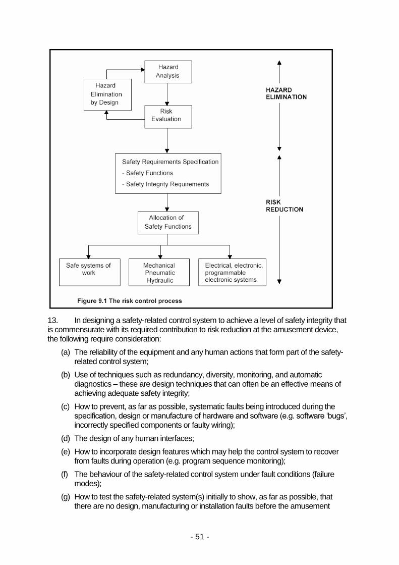
- 51 -
13. In designing a safety-related control system to achieve a level of safety integrity thatis commensurate with its required contribution to risk reduction at the amusement device,the following require consideration:
(a) The reliability of the equipment and any human actions that form part of the safety-related control system;
(b) Use of techniques such as redundancy, diversity, monitoring, and automaticdiagnostics–these are design techniques that can often be an effective means ofachieving adequate safety integrity;
(c) How to prevent, as far as possible, systematic faults being introduced during thespecification, design or manufacture of hardware and software (e.g. software ‘bugs’, incorrectly specified components or faulty wiring);
(d) The design of any human interfaces;
(e) How to incorporate design features which may help the control system to recoverfrom faults during operation (e.g. program sequence monitoring);
(f) The behaviour of the safety-related control system under fault conditions (failuremodes);
(g) How to test the safety-related system(s) initially to show, as far as possible, thatthere are no design, manufacturing or installation faults before the amusement

- 52 -
device is put into operation;
(h) How to design periodic test and inspection procedures for the safety-related controlsystem(s) for the lifetime of the amusement device to show that no part (includingboth hardware and software) has changed or deteriorated beyond reasonable limits.
14. These issues should be taken into account for all elements of the safety-relatedcontrol system, including hardware, software, the way that parts are combined duringintegration, and any humans on whom the functionality of the system may rely. It should berecognised that all these elements may contribute towards the safety integrity of theindividual safety functions and the performance of each element therefore needs to beconsidered when assessing safety integrity.
15. The following points aim to assist in the process of designing safety-related controlsystems for amusement devices. They are applicable to new devices, devices beingrefurbished to present day standards and to older devices being reassessed for the purposeof improving safety.
(a) Identify the hazards occurring at the device, taking into account the hazards thatarise in normal operation, during maintenance, and in foreseeable abnormalconditions such as break-down.
(b) Assess the risks from the device. If the risks are determined to be unacceptable,consider designing them out. If this is not possible, determine the risk reductionmeasures required to reduce the risks to a tolerable level (see Chapter 1).
(c) Allocate safety functions to appropriate combinations of risk-reduction measures,such as positioning, fixed guards, passenger restraints, speed and accelerationcontrol, anti-collision mechanisms, and emergency stops.
(d) Determine which of these risk reduction measures require a safety-related controlsystem.
(e) For each safety function, determine the contribution required from the safety-relatedcontrol system to achieve the necessary level of risk reduction.
(f) Draw up the safety requirements specification that assigns a required safety integrityto each of the safety functions. The required safety integrity is a measure of thetarget dangerous failure rate, which is based on the tolerable risk determined as partof the risk assessment process.
(g) Design the safety-related control system. The design process should includeconsideration of the consequences of failures, which may require the application ofreliability analysis techniques such as Failure Mode and Effects Analysis (FMEA),reliability block diagrams, cause consequence analysis, and fault tree analysis. Thedesign should consider failures within purpose built control units, such as electronicmotor drives, as well as those in circuitry external to the drives.
(h) Validate the design to ensure that it meets the requirements of the SafetyRequirements Specification. Document the process so that anyone who needs tocan understand how and why the system meets the safety requirements.
16. Designers should provide information on an appropriate in-service maintenanceregime incorporating inspections, tests and any required component replacementschedules. To maintain safety integrity, all safety-related control systems should be testedregularly as part of a preventative maintenance strategy.
17. For any particular safety-related control system, the frequency of testing should be

- 53 -
determined taking into account:
(a) the safety integrity requirements;
(b) the target dangerous failure rate;
(c) the reliability of the component parts;
(d) the degree of fault tolerance; and
(e) the diagnostic capabilities of the safety-related control system.
Programmable Safety-Related Control Systems
18. Some amusement devices have control systems that incorporate programmableelectronic systems such as programmable logic controllers (PLC), embeddedmicrocontrollers and microprocessors, and smart sensors. The cost, flexibility andconfiguration advantages of using such devices are well known, but considerable careshould be taken if it is proposed to use programmable electronic systems for implementingsafety functions.
19. As with any safety-related control system on an amusement device, those thatincorporate a programmable electronic system need to perform the required safety functionswith a suitable degree of safety integrity. This will be influenced to a large extent by theprogrammable electronic system’s susceptibility to random hardware failures, and also to systematic failures within its hardware and software (operating and application).
20. As the failure modes of programmable electronic systems are not well defined andtheir behaviour under fault condition cannot be readily determined, safety-related controlsystems incorporating such technology must be regarded as complex systems. Thisclassification is a fundamental factor in the selection of which standard to apply to the designof the safety-related control system (see fig.8.2).
21. Although they may be adequate for performing non-safety-related control functionson amusement devices, general-purpose programmable electronic systems such as PLCsshould not be assumed to be suitable for use in safety-related control systems. To determinetheir suitability for implementing safety functions, the performance of the overall safety-related control system would need to be assessed against relevant standards, which mightindicate that the required safety integrity can only be achieved by adopting additionalmeasures to protect against failure of the hardware and software of the programmableelectronic system. Alternatively, the safety functions could be performed by supplementarycontrol circuits that do not depend on the correct operation of the PLC.
22. In the absence of additional measures being used, the safety integrity of any PLC orsimilar programmable electronic system used in a safety-related application should equal orexceed to that of the most critical safety function that it performs. This also applies to theapplication software (e.g. ladder logic, function blocks) or configuration of such devices.
23. Programmable electronic systems are available that have been specificallydesigned and assessed for use in safety-related applications by following a rigorous andsystematic design approach such as that offered by IEC 61508 . Their designs typicallyincorporate enhanced redundancy, diagnostic and monitoring techniques to reduce thelikelihood and impact of random hardware failures, and diversity to reduce the likelihood ofsystematic errors inducing common cause failures.
24. Measures should be taken to ensure that software for programmable electronicsystems used in safety-related applications does not contain systematic faults. Since it is

- 54 -
generally recognised that software cannot be tested with sufficient confidence to detect allsuch faults, software developers should minimise the likelihood of errors being introducedduring the specification and development of the software by ensuring that the project is wellmanaged within a structured framework. This will include progressive verification, validationand testing of the software components throughout the development cycle including anyfinal development work during commissioning activities. Compliance with IEC 62061 andIEC 61508-3 (Software requirements) will demonstrate that good practice has beenfollowed.
25. Within this framework, the accuracy and completeness of the initial specification forthe requirements for safety performance in the control system is of fundamental importance -if the initial specification is deficient, the follow-on stages in the development cycle may notprevent systematic faults from being inadvertently introduced.
26. If the end-user has the facility to alter the application software, rigid procedures tocontrol, assess and validate any changes are crucial. Although programmable electronicsystems can make the physical task of modifying a safety-related control system relativelyeasy compared to wiring modifications in a hard-wired safety-related control system, skillsand competencies in machinery safety issues are still vital. Modifications should only beundertaken by persons who possess the competencies that enable them to understand theimplications of their actions.
27. If a field-bus system is to be incorporated into a safety-related control system, theoverall system should satisfy the safety integrity requirements of each safety function. Field-bus systems suitable for transmitting safety-related data would have typically been designedand assessed for use in safety-related applications by following a rigorous and systematicdesign approach such as that of IEC 61508. The safety integrity capability of a field-bussystem should equal or exceed that of the most critical safety function for which it transmitssafety-related data.
28. Although a programmable electronic system that has been designed and assessedspecifically for use in a safety-related control system may be certified to a particular safetyintegrity, it is the risk reduction capability of the overall safety-related control system thatshould be checked against the Safety Requirements Specification during validation. Acomponent part intended for use in a safety-related control system is only effective if theoverall system has been appropriately designed, integrated and validated, all of whichrequire specific competencies.
29. It is essential that work on the specification, design and development ofprogrammable safety-related control systems takes full account of the concepts of capturingsafety requirements; safety validation; safety-related system architecture design, hardwareand software realisation; and project safety assurance.
Non-Programmable Safety-Related Control Systems
30. This type of safety-related control system does not contain programmable electronicsystems, although it is recognised that systems implemented in non-programmabletechnologies can actually be quite complex in nature. They include electromechanical relay-based systems, hydraulic and pneumatic systems, and mechanical systems that can beassessed using deterministic principles.
31. The general principles for the design of these systems are similar to those used forprogrammable electronic systems. This is because the requirements should be based on afundamental assessment of the risks created by the device and the extent to which the

- 55 -
safety-related control system is needed to reduce those risks to a tolerable level, taking intoaccount all other measures taken to control the level of risk.
32. In many cases a safety-related control system based on programmable electronicsystems will also comprise non-complex electrical and electronic parts such as interlockingswitches and interposing relays. Prior to integrating such parts, the system designer must beable to fully determine whether their application will achieve the appropriate level of safetyintegrity.
Use of Standards for Safety-Related Control Systems
33. Guidance on the processes and procedures appropriate to the design anddevelopment of electrical, electronic and programmable electronic (E/E/PE) technologybased safety-related control systems is set out in the basic safety publication IEC 61508,which is regarded as the authoritative good practice in this field. It uses the Safety Lifecyclemodel to indicate the measures that should be applied from the conceptual design phasethrough to decommissioning, describing both quantitative and qualitative methods of controlsystem analysis. Although IEC 61508 has been formally adopted across Europe, it is notactually harmonised to a specific Directive.
34. As a basic safety publication, IEC 61508 is intended to be used by IEC technicalcommittees during the development of sector or product standards that have E/E/PE safety-related system considerations. IEC 62061, which is a machinery sector implementation ofIEC 61508, provides a framework for designers of E/E/PE safety-related control systems formachines to achieve functional safety. The scope of IEC 62061 is applicable to E/E/PEsafety-related control systems of any complexity, including high complexity systems thatincorporate programmable electronic systems. As with IEC 61508, it has also been adoptedacross Europe, but in addition it has been harmonised under the Machinery Directive.
35. EN 954–1, which is also harmonized under the Machinery Directive, providescriteria by which the safety-related parts of control systems based on all operating media canbe categorised according to their fault resistance and behaviour under fault conditions.Although the scope of EN 954-1 does not exclude complex safety-related control systemssuch as those incorporating programmable electronic systems, the standard is mostapplicable to low complexity safety-related control systems, i.e. those in which the failuremodes of components are well defined and the behaviour of the system under faultconditions can be completely determined.
36. Further justification for restricting the application of EN 954-1 to low complexitysystems is based on the fact that it does not consider systematic failures, which tend to beincreasingly significant in complex systems. Also, it does not provide information onvalidation techniques for when programmable electronics are used in the design of safety-related parts of control systems, instead referring to other standards such as IEC 61508.
37. Although the exclusion of amusement devices from the scope of the MachineryDirective means that harmonised standards such as EN 954-1 and IEC 62061 have noformal status, they are nevertheless a useful source of guidance for the design of safety-related control systems for amusement devices. Amusement device designers shouldtherefore decide on the appropriate standard that can be applied to the safety related controlcircuits, with the flow chart in Figure 8.2 aiding this decision.
EN 954-1
38. This Standard categorises safety-related control systems, in total or in part,
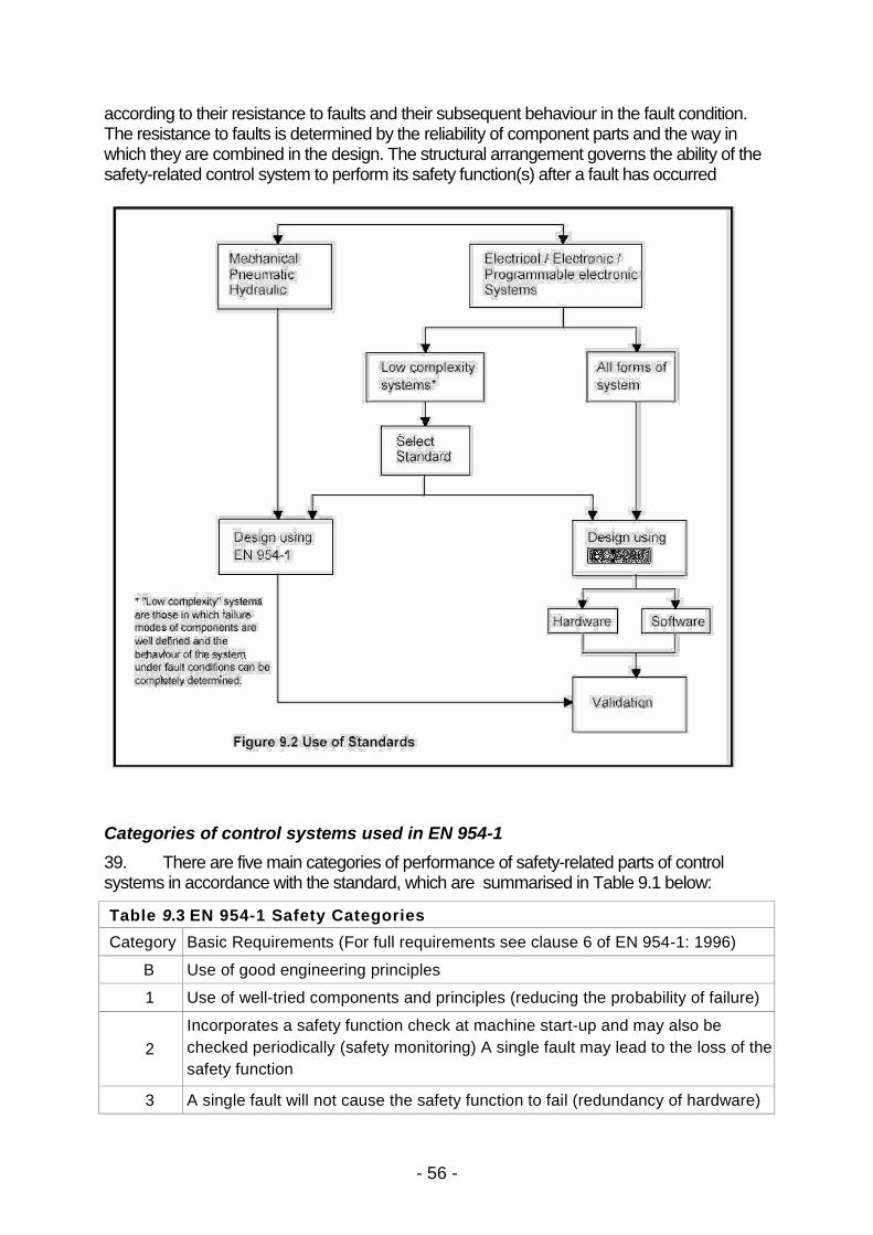
- 56 -
according to their resistance to faults and their subsequent behaviour in the fault condition.The resistance to faults is determined by the reliability of component parts and the way inwhich they are combined in the design. The structural arrangement governs the ability of thesafety-related control system to perform its safety function(s) after a fault has occurred
Categories of control systems used in EN 954-1
39. There are five main categories of performance of safety-related parts of controlsystems in accordance with the standard, which are summarised in Table 9.1 below:
Table 9.3 EN 954-1 Safety Categories
Category Basic Requirements (For full requirements see clause 6 of EN 954-1: 1996)
B Use of good engineering principles
1 Use of well-tried components and principles (reducing the probability of failure)
2Incorporates a safety function check at machine start-up and may also bechecked periodically (safety monitoring) A single fault may lead to the loss of thesafety function
3 A single fault will not cause the safety function to fail (redundancy of hardware)

- 57 -
Table 9.3 EN 954-1 Safety Categories
4A single fault will not lead to a loss of the safety function. The single fault isdetected at or before the next demand upon the safety function, or anaccumulation of faults will not lead to a loss of the safety function.
Application of EN 954-1
40. It is important to bear in mind that safety-related parts of control systems may notneatly fit into a single category, particularly if they use different energy sources - a controlsystem can incorporate electrical, electronic, programmable electronic, pneumatic orhydraulic devices.
41. Categories should not be regarded as hierarchical with regard to safety. Forexample, a single positively operated safety switch element that has been manufactured to apublished safety standard might, itself, meet the requirements of Category 1, but not thecriteria for higher categories. However, its level of safety performance could be considered atleast as high as technologies with structures that meet Categories 2 and 3, but for which thecomponent reliability is inferior in comparison. The selection of categories for the safetyfunctions listed in the rest of this Chapter is therefore a matter of judgment that should bepart of a risk assessment (see Chapter 1) and failure analysis.
42. The technical report PD CR 954-100: 1999 provides further guidance on use andapplication of EN 954-1, whilst ISO 13849-2 (effectively part 2 of EN 954) covers the processof validation of the safety-related parts of control systems of the machine.
Future of EN 954-1
43. EN 954-1 will at some point in the future be replaced by ISO 13849-1, which alsoapplies to safety-related parts of control systems based on all operating media.
44. ISO 13849-1 introduces the concept of a ‘Performance Level’, which is a hierarchical and quantitative measure of the ability of a safety-related part of a controlsystem to perform its associated safety function.
45. There are 5 discreet performance levels (a-e), each corresponding to a range ofprobability of dangerous failure per hour of the safety-related part of the control system.
46. The Performance Level of a safety-related part of a control system is a function ofseveral parameters, including structure (EN 954-1 category classification), component failurerates and diagnostic capability.
IEC 62061
47. Guidance on the processes and procedures appropriate to the specification, designand validation of machinery safety-related control systems implemented in E/E/PEtechnologies is published in IEC 62061, which applies the principles of IEC 61508 tomachinery applications.
48. IEC 62061 contains advice on the system hardware and software architecturesaimed at achieving an adequate level of safety integrity. A quantitative analysis concept thatwas first introduced in IEC 61508 is that of Safety Integrity Levels (SILs), which specify thetarget failure values in terms of probability of a dangerous failure per hour and probability offailure to perform on demand.

- 58 -
49. Although IEC 61508 considers SILs ranging from SIL1 to SIL4, the scope of IEC62061 does not extend to SIL4 - the highest level of safety integrity - as it is not consideredrelevant to the risk reduction requirements normally associated with machinery.
50. Furthermore, IEC 62061 quantifies SILs solely in terms of a failure rate (forcontinuous mode and high demand rate safety functions) and not in terms of a probability offailure on demand (for low demand rate safety functions), since the low demand mode ofoperation is not considered to be relevant for machinery applications.
51. Table 9.4 shows the range of probability of dangerous failure per hour for eachvalue of SIL relevant to IEC 62061.
Table 9.4 IEC 62061 Safety Integrity Levels
SIL Probability of a dangerous failure per hour
4 Not applicable
3 ≥ 10-8 to <10-7
2 ≥ 10-7 to <10-6
1 ≥ 10-6 to <10-5
52. The required SIL of a safety function is determined by the initial risk assessment, theanalysis of the amusement device safety requirements and the level of risk consideredtolerable in the specific application. The safety function will need to have a SIL value thatreduces the initial risk to a level that is at least as low as this tolerable risk. It is essential thatthis analysis is undertaken by a competent person.
53. Examples of methods for assigning SILs to safety functions can be found in IEC62061 (Annex A) and IEC 61508-5. When applying techniques such as these, it should beremembered that the acceptable probability of occurrence for a particular hazardous event isspecific to the application. Determining the tolerable risk for a particular situation thereforerequires many factors to be considered. It is only when this tolerable risk has been decidedthat the SIL required to adequately reduce the risk to this level can be determined.
54. A SIL is assigned to each safety function in a safety-related control system and hasa strong influence on the requirements that have to be taken into account during the designand integration of a safety-related control system. These measures, together with thecalculation of failure rates for the safety-related control systems, are an integral part of theprocess of achieving a safe design.
55. Central to IEC 62061 are the Safety-Related Electrical Control System (SRECS)and the Safety-Related Control Function (SRCF). These relate to the E/E/PE elements of amachine’s safety-related control system and the control function to be performed by it.
56. A SRCF will be specified in terms of its particular role or function and the safetyintegrity associated with the performance of this function. Where a SRECS is used toimplement one or more SRCFs, its hardware and software must achieve a SIL consistentwith the highest safety integrity requirements of the individual SRCFs.
57. The SIL that can be claimed for a SRECS consisting of one or more subsystems willbe constrained by the lowest SIL Claim Limit of any subsystem and by their combinedprobability of dangerous random hardware failure. The SIL Claim Limit of a SRECS

- 59 -
subsystem determines the maximum SIL that can be claimed in relation to its architecturalconstraints and its systematic safety integrity (extent to which systematic failure avoidancemeasures have been applied). For a SRCF to achieve a particular SIL, the SIL Claim Limitof each SRECS subsystem must therefore equal or exceed it, and their combined probabilityof dangerous random hardware failure must not exceed the target failure value for that SIL.The example of a SRECS design covered by Annex B of IEC 62061 illustrates this concept.
Comparing SILs and Categories
58. The fact that categories in EN 954-1 and SILs in IEC 62061 both share allocatednumbers 1 to 3 does not mean that there is a direct relationship between them. Bothstandards are written from different perspectives and so SILs and Categories are notcomparable measures. Categories are not to be assumed as hierarchical measures for allapplications” with “a hierarchical measure across technologies, whereas SILs arehierarchical because they relate to probabilities of failure.
59. A safety-related control system comprised entirely of components meeting therequirements of EN 954-1 category 4 may reasonably be expected to meet the target failurevalue (probability of dangerous failure of the SRCF per hour) associated with SIL 3 .However, no assumption should be made about the target failure measure achieved bysafety-related systems which include components to EN 954-1 categories B, 1, 2 or 3,because EN 954-1 has no quantified requirements on the likelihood of dangerous failure forthese categories. Whereas the category of a safety-related control system relates chiefly toits structure, and therefore its hardware fault tolerance, its SIL is based on its probability ofdangerous random hardware failure and the constraining effect of the maximum SIL ClaimLimit (see para. 57).
60. For low complexity subsystems that have been designed in accordance with EN954-1 and validated in accordance with ISO 13849-2 (effectively part 2 of EN 954), IEC62061 provides a methodology for integrating them into a SRECS. The Category, SafeFailure Fraction10 and Diagnostic Coverage11 of the subsystem are used to derive amaximum SIL Claim Limit based on architectural constraints only, and a threshold value forprobability of dangerous failure. Consideration of the systematic safety integrity aspectsenables an overall maximum SIL Claim Limit to be determined.
61. This maximum SIL Claim Limit based on architectural constraints is a function of thecategory (hardware fault tolerance) and Safe Failure Fraction combination, whilst thethreshold value for probability of dangerous failure is determined by the combination ofcategory (hardware fault tolerance) and Diagnostic Coverage. Consideration of thesystematic safety integrity aspects enables an overall maximum SIL Claim Limit to bedetermined, which in conjunction with the probability of dangerous failure indicates the SILfor a complete safety-related control system.
62. The Performance Levels used by ISO 13849-1, which are derived in part from EN954-1 categories, will be more comparable with SILs, as they are both quantitative andhierarchical measures of performance.
Safety Functions and Detailed Requirements for Amusement Devices
10 Fraction of the overall failure rate of a subsystem that does not result in a dangerous failure.11 Percentage decrease in the probability of dangerous hardware failures resulting from the operation of theautomatic diagnostic tests.

- 60 -
Stop and associated functions
63. When necessary (as decided by the risk assessment) the safety-related controlsystem should provide the facility for, safety stopping and emergency stopping of theamusement device. Operational stopping, for example for loading and unloadingpassengers, is implemented by the primary control system
64. Stop functions should have priority over related start functions.
65. Stop functions may be provided in separate systems or in a single systemdepending upon the risk.
Safety stop function12
66. This function is intended to avert actual or impending danger and may be activatedeither manually or automatically. It should stop the relevant parts of the amusement deviceso as to reduce the overall risk to an acceptable level as quickly as possible.
67. A safety stop function should override operational stop functions but not emergencystop functions.
68. After a safety stop has been initiated, a restart may not take place until the cause forthe stop has been removed.
69. The relevant parts of the amusement device should reach standstill in the shortesttime commensurate with avoiding hazardous conditions with due regard to all safetyrequirements including:
(a) general integrity of the machine and structure;
(b) safe accommodation of passengers; and
(c) decelerations.
Emergency stop function
70. Provision should be made, where indicated by the risk assessment, for a manuallyinitiated emergency stop. The emergency stop should conform with the requirements of EN418 and should function as either a stop category 0 or stop category 1 as defined in EN60204 -1, depending upon the outcome of the risk assessment.
(a) A category 0 stop is caused by immediate removal of power
(b) A category 1 stop is a controlled stop with power available to the machine actuatorsto achieve the stop and then automatic removal of power when the stop is achieved.
71. Manual emergency stop actuators should be placed in positions that are easilyaccessed by appropriate operators, attendants, maintenance personnel, and in somecircumstances passengers, who may need to stop the device for safety reasons.
72. Subject to risk assessment and operational considerations, the amusement deviceshould reach standstill in the shortest time commensurate with avoiding hazardousconditions with regard to all safety requirements including:
(a) general integrity of the machine and structure;
12 In some applications, a safety or emergency stop may result in such problems as difficult recovery ofpassengers and / or restart. If a stop could arrest the ride in other than the normal operating stop position, meansshould be provided, e.g. by fixed platform, so that the passengers may be disembarked safely

- 61 -
(b) safe accommodation of passengers; and
(c) decelerations.
73. After an emergency stop has been initiated, a restart may not take place until afterthe cause for the stop has been removed. An emergency stop may be over-ridden to allowthe safe recovery of passengers by trained personnel who should follow a safe system ofwork, but this should not allow the ride to be operated in normal operational mode while therecovery operation is taking place
Other safety functions
74. Single mechanically-actuated sensing devices (e.g. limit switches) on interlockingand / or monitoring systems should be actuated in the positive mode or where this is notreasonably practicable be monitored so that any failure that may lead to danger is detectedand acted upon to ensure safety as determined by risk assessment.
(a) Subject to risk assessment, unmonitored negative mode devices should not beused.
(b) The risk assessment may also determine that positive mode switches may still needto be monitored so that any failure that may lead to danger is detected
75. Where the risk assessment shows it to be necessary, interlocking and monitoringdevices should be selected and positioned so that they are not easily or accidentallydefeated or interfered with by persons riding in or on the amusement device.
76. In block zone systems any paired (providing redundancy) sensors should normallybe configured so that:
(a) For entry to the block either one sets the block as occupied (OR in logic terms).
(b) For exit from the block both are required to reset the block to free (AND in logicterms).
77. The designer should specify, for inclusion in the Operations Manual, the limits of anyadjustments and any necessary checks and / or tests needed to confirm the correctadjustment and operation of the interlocking and / or monitoring system.
Safety related parameters
General
78. Means should be provided to ensure that the values of the safety relatedparameters stay within predetermined levels defined by the risk assessment. A safety-related parameter is a variable which may be adjusted manually or as part of normaloperation and which, if it moves outside predetermined boundaries, may lead to danger.
Speed
79. Speed is an important safety critical parameter for amusement devices whereaccelerations, and consequently forces, are dependent on the speed of amusement rideelements. Therefore, speed control can prevent hazardous effects on structures andpassengers.
80. The following speeds should be considered.

- 62 -
(a) Minimum operational speed: The minimum speed necessary to ensure, for astated operational condition, the safe containment of passengers and the intendedfunction and the integrity of the amusement device.
(b) Normal operational speeds: Speeds at which the device will normally runand which will be between the minimum operational speed and the maximumoperational speed. The speed may vary during the ride cycle.
(c) Maximum operational speed: The maximum speed at which, for a statedoperational condition, the safe containment of passengers and the intended functionand the integrity of the amusement device are ensured during repeated or sustaineduse.
(d) Maximum achievable speed: The maximum value of speed achievable by anamusement device element, without any restriction of control.
81. For a particular part of the ride cycle there may be different operating speeds. Inparticular, subject to the penultimate sentence of this paragraph and paragraph 54 below,the following safety functions should apply to prevent the amusement device operatingoutside the design parameters.
(a) The control system should control the speed between the minimum and maximumoperational speeds for that part of the ride cycle.
(b) If the device either fails to achieve a minimum operational speed after apredetermined time, or the speed falls below the minimum operational speed, thenthe control system should perform a safety stop.
(c) If the speed of the device rises above the maximum operational speed, then thecontrol system should perform a safety stop.
In some cases, risk assessment may show that one or more of these safety functions is notrequired. In others, it should be used to justify the safety category or safety integrity level.
82. The risk assessment should evaluate the effects on the structure and/or machineand passengers due to any achievable speeds.
83. If the maximum achievable speed is lower than or equal to the maximumoperational speed, the control system does not require additional speed limiting circuits. Butif the maximum achievable speed is greater than the maximum operational speed, takinginto account foreseeable fault conditions, additional means may be necessary to ensure thatthe maximum operational speed is not exceeded. Also if the machine does not reach, orfalls below, the minimum operational speed, additional means may be needed to ensure thatthe minimum operational speed is achieved or a safety stop is performed.
84. In some amusement devices (e.g. those in which a multiple passenger unit is madeto swing and/or rotate about a horizontal axis) the instantaneous positions, speeds andaccelerations may be very dependent upon the design of the control circuits. Full details ofcontrol, including feedback characteristics, need to be available for use in the stressanalysis.
Passenger restraint device status and behaviour
85. Where a control system is involved in the operating, interlocking or monitoring ofpassenger restraint devices, its safety function and required safety integrity should bedetermined from the risk assessment.

- 63 -
86. Guidance on the principles for the design and selection of interlocking devices ispublished in EN 1088, and guidance on their incorporation into safety related controlsystems is also available in BS PD 5304. These two standards relate specifically to guardingof machinery. However they do contain some useful advice applicable to interlockingsystems on amusement devices. Interlocking systems are not always necessary,appropriate, or practical to be installed on an amusement device.
87. The following guidelines should be taken into account. Any departures from theseguidelines should be detailed and justified in the risk assessment.
(a) Positioning for starting
i. Closure and locking of restraints should be confirmed either by personnel orautomatic systems before starting the ride cycle.
ii. This confirmation need not be automatic.
(b) Enabling of release
i. Control systems should not allow the release of the restraint devices unless it issafe to do so or unsafe not to do so.
(c) Alarms and warnings
i. Where an operator relies on audible alarms or visible indications as evidence thatrestraint devices are locked in the closed position, such alarms or indicationsshould have the necessary safety integrity as indicated by the risk assessment inaccordance with Chapters 1 and 10 of this Guidance.
(d) Loss of power supply should not:
i. allow the automatic release of restraint devices unless such release would notendanger the passengers or a suitable system of work is in use to ensurepassenger safety.
ii. prevent the intentional release of restraint devices when required to ensure thesafety of the passenger or for operational purposes, e.g. manual release.
(e) Monitoring of position
i. The need for the monitoring of the position of passenger restraint devices andtheir interlock latches should be determined by the risk assessment incompliance with Chapters 1 and 10 of this Guidance.
Inhibiting or bypassing of safety functions
88. The inhibiting or bypassing of safety functions should not result in any person beingexposed to hazardous situations. When safety functions are inhibited or bypassed, safeconditions should be provided by other means. Removal of inhibits or bypasses shouldresult in all safety functions of the safety-related parts of the control system beingautomatically reinstated.
89. If it is necessary to manually suspend safety functions, e.g. for set up, adjustments,maintenance, and repair, the following criteria should be applied:
(a) reinstatement of the safety functions of the safety-related parts of the control systembefore normal operations can be continued;
(b) effective and secure means to prevent manual suspension in those operating
- 64 -
modes where it is not allowed;
(c) depending upon the risk assessment, consideration should also be given to theprovision of a mode selection device or means capable of being secured (e.g.locked) in the desired mode so as to prevent automatic operation. In addition,consideration may need to be given to the provision of one or more of the following:
i. initiation of motion by a hold–to - run device or by a similar control device;
ii. a portable control station (e.g. pendant) with an emergency stop device and,where appropriate, an enabling device. Where a portable station is in use, motionmay be initiated only from that station;
iii. limitation of the speed or the power of motion.
Control modes
90. Control systems should have one or more control modes relevant for theirapplication. Control modes can be divided into:
(a) pre-operating modes (without passengers) such as for setting, adjustment,programming, testing, cleaning, maintenance, trouble shooting and repair;
(b) operating modes such as manual, semi-automatic and automatic cycle, foroperation with passengers. There may be variations and combinations of operatingcycles;
(c) non operating modes where the pre-operating or normal operating mode is notpossible due to abnormal circumstances.
Change of control mode
91. A change of control mode should not cause a hazardous condition. It may benecessary to:
(a) bring the ride to a stop, requiring an operator start command to restart the ride,following a change of control mode;
(b) prevent inadvertent change of control mode, including unexpected start-up; or
(c) bring a change of control mode to the attention of the operator.
92. The following requirements should also be adopted where necessary:
(a) the appropriate mode selector should be so located that it can be operated safely;
(b) when a hazardous condition can result from a mode selection, such selectionshould be prevented by suitable means (e.g. key operated switch, access code);
(c) mode selection by itself should not lead to initiation of motion of any passenger unit–a separate action should be required;
(d) safeguarding should remain effective for all operating modes;
(e) indication of the selected operating mode should be provided (e.g. the position of amode selector, the provision of an indicating light, a visual display indication).
Pre-operating mode
93. When in pre-operating mode the amusement device should operate only by a

- 65 -
separate action of the operator. The following conditions should be met:
(a) An authorised person should be in overall control.
(b) Depending on the risk assessment, the control of more than one subsystem whichcould cause a hazard should either be prevented by the safety-related controlsystem or be under the sole control of a single operator.
(c) Depending on the risk assessment, safety functions should either continue tooperate or be under the sole control of a single operator.
(d) All system emergency stops should remain effective.
Operating modes
94. There may be more than one operating mode. The amusement device shouldoperate only after an initiation by the operator or under his supervision.
95. These modes are the only control modes which are allowed for normal operationwith passengers, and all the safety functions should be in use.
96. In general, operating modes can include:
(a) manual, if all operating cycles are under the control of the operator;
(b) semi-automatic, if part of the operating cycle is controlled by means of one or moreautomatic program;
(c) automatic, if all operating cycles are controlled by means of one or more automaticprogram.
97. In operating modes, the following requirements should be met;
(a) The cycle should be initiated by the operator apart from special cases, such ascontinuous loading and unloading, and providing the risk assessment allows it;
(b) Means should be provided if necessary to prevent the ride time exceeding apredetermined value based on passenger discomfort;
(c) The selection of other operating modes or programs should not cause a hazard;
(d) During passenger loading or unloading mode, when the ride is at rest, it should notbe possible for the ride to start, or move inadvertently, unless the operator hassignalled the control system to do so. The required safety integrity level of this safetyfunction should be determined from the risk assessment.
(e) Amusement devices in which loading and unloading occur without the devicecoming to a stop should be provided with a built-in device or procedures to ensurethat the operator maintains his supervision of the ride. The speed of the deviceduring loading and unloading should be treated as a safety-related parameter.
Non-operating mode
98. The amusement device, either whole or in part, is considered to be in a non-operating mode if, for example, any of the following occurs:
(a) Loss of power
(b) Restoration of power
(c) Actuation of an emergency stop

- 66 -
(d) Initiation of a safety stop
99. The safety related control system should ensure that:
(a) at any point in time, the state of the amusement device in non operational conditionsdoes not lead to a hazard; and
(b) any safety critical parameters and data in the control system (preset or otherwise)should be maintained even during the course of operation resulting from safety oremergency stop or an equivalent event. If this is not possible, alternative meansshould be specified in order to ensure safety.
100. During the slowing and the stopping of the ride:
(a) a safe sequence of events should be followed; and
(b) the constraints set by the minimum operational speed and/or deceleration forces,applicable at the time, should be complied with.
101. Where loss of power could result in a dangerous condition, a reserve of energyshould be available to provide the power necessary to enable the ride to be brought to restand remain at rest, or other means should be provided to ensure safety.
102. Any reinstatement of power after a power loss should not automatically restart theride without a command by the operator.
103. In the non-operational mode the following conditions should be met in addition tothose required for the pre-operating mode:
(a) Operations, whose combination could simulate the operating mode or could lead tohazardous conditions, should be allowed only in confirmed discrete steps by thesafety-related control system. Suitable means should be provided to ensure thateach separate operation is deliberately actuated.
(b) Notwithstanding a) above safety functions should remain effective in thoseoperations where, if overridden, a more hazardous condition could occur.
(c) If the only way to recover passengers is to use the built-in override of a safetyfunction, this special procedure should be performed by an authorized operator andbe visually monitored either by that operator or by a subordinate in goodcommunication with him.
Collision prevention by control systems
104. Where required by a risk assessment a means of preventing unintentional collisionsshould be provided. An example of such means, a block-zone system, is provided.

- 67 -
Block-zone control system
A block-zone control system consists of the partial or complete subdivision of the ride circuit intosections, called block-zones, each of which should not be occupied by more than one passengerunit or train at the same time, except as allowed below.
The number of block-zones into which the ride circuit is subdivided should be sufficient to preventunsafe collisions. In some devices dependent on the risk assessment more than one passenger unitmay be allowed into, or to overlap into, one or more of the block-zones with safety being assured byother means. For example, speed may be restricted and / or buffering may be provided to allowpassenger units to come into contact with each other at station areas or immediately before a lift ina log flume.
A block-zone control system normally includes the following elements:
a means of signalling the occupied status of a block-zone e.g. occupancy sensors; a means of signalling the clear status of a block-zone (clearance sensors); control logic; devices which can stop the passenger unit when necessary within the required distance to
prevent collisions (e.g. stopping devices).
Subject to risk assessment, the control system should perform a safety stop in the case ofequipment failure which could lead to an increase in the risk to passengers; e.g. the failure of oneout of a set of redundant sensors, or loss of power. The risk assessment should determine whether itis safer to allow unaffected passenger units, such as those ahead of a failed sensor, to carryonwards to a suitable disembarkation point, or even the normal disembarkation point.
On restoration of power (including electrical, hydraulic or pneumatic), if there is no automaticsystem to ensure the safe restart of block-zone operation, the system should prevent the opening ofbrakes or the initiation of movement except under a manual system of work. If an automatic restartis provided, it should be initiated manually.
In any block-zone, clearance sensors should be so located that if the passenger unit stops for anyreason as soon as it leaves the block-zone, the following unit should be prevented from collidingwith it even if stopped in the most unfavourable condition possible.
Sensors should be so located and / or control logic designed such that a block-zone is recognised asoccupied before the previous block-zone is cleared.
Requirements for stopping devices
105. All brake or stopping systems should conform to the following requirements:
(a) The total required number of stopping units within a group should be determined byrisk assessment.
(b) For a group of redundant brakes or stopping units, loss of power from or componentfailure of any brake or stopping unit, or a defined number of units as decided by therisk assessment, should not reduce the ability of the remaining stopping units withinthe group to bring a passenger unit to a safe halt.
(c) Stopping devices should be located so that, after a stop, the passenger unit, innormal conditions, can be restarted safely.
(d) The brake system should operate, when demanded to do so for safety reasons,within a time that will enable a ride to be brought to a halt within the requireddistance, no matter what the environmental or operational conditions.
(e) The control of final actuating systems of stopping devices (whether electrical,electronic, mechanical, pneumatic or hydraulic) should either:

- 68 -
i. cause the passenger carrying device to stop within safe limits in their de-energised state; or
ii. if any elements are energised to cause the stop, then an adequate level of safetyshould be provided by means such as redundancy and/or diversity.
106. Powered lifting or shifting devices may be used as stopping devices under thefollowing conditions:
(a) The device should have the ability positively to halt the passenger unit or train insuch a position that it is not possible for any external influence such asenvironmental conditions or change in load to cause it to continue.
(b) The device should be de-energised by suitable means, such as contactors, and thepassenger unit or train effectively should be prevented from reversing in adangerous manner by an anti-rollback device.
(c) An electronic device may be used to bring any device or motor speed to zero.However, if the speed does not reduce to zero within a safe distance, or if theelectronic device restarts, then the supply to the final actuator or motor should bephysically interrupted, e.g. by means of contactors, or other diverse means.
(d) The device, as well as any control circuits, whether electrical, electronic, pneumaticor hydraulic, should either:
i. cause the passenger carrying device to stop within safe limits in de-energisedstates, or
ii. if any elements are energised to cause the stop, then an adequate level of safetyshould be provided by means such as redundancy and/or diversity.
107. When a device is used to trim the speed of the passenger unit or train and also as astopping device and if the trimming or stopping function has safety implications, then thesensors, control logic and the devices should be considered as part of the safety-relatedsystem and treated accordingly. In cases where trimming has no safety implications this partof the control system need not be safety-related.

- 69 -
Relevant Standards & Other Publications
EN 418 Safety of machinery: Emergency Stop Equipment.EN 954-1 Safety of machinery–Safety Related Parts of Control
Systems Part 1: General Principles of DesignISO 13849-2 Safety of machinery–Safety-related parts of control
systems–Part 2: ValidationPD CR 954-100 Safety of machinery–Safety-related parts of control
systems–Part 100: Guide on the use and application ofEN 954-1:1996
EN 1050 Safety of machinery–Principles of Risk Assessment.EN 1088 Safety of machinery–Interlocking devices associated
with guards. Principles for design and selectionPD 5304 Safe use of machinery.EN 60204-1 Safety of machinery–Electrical equipment of machines.
Specification for general requirementsIEC 61508 Functional safety of electrical / electronic /
programmable electronic safety-related systemsIEC 62061 Safety of machinery–Functional safety of safety-related
electrical, electronic and programmable electroniccontrol systems

- 70 -

- 71 -
Chapter 10
Passenger Units and Containment
General principles
1. The passenger units13 should be designed to contain safely all passengers for whomthe Operations Manual states that the ride is suitable. To achieve this the designer needs tospecify the target population for the ride, e.g. maximum and minimum size / weight and otherphysical limitations.
2. The sizing criteria for passengers should be such that they can be measured anddistinguished easily by the ride attendants with minimal or no ambiguity.
3. The designer needs to provide secure and safe accommodation for passengers atall stages during the ride cycle and foreseeable emergency situations e.g. the application ofemergency brakes.
4. Safe and secure accommodation includes minimising the risk of injury from thefollowing causes:
(a) physical injury within the confines of the passenger unit
(b) injury due to forces that result in adjacent passengers being pushed together
(c) moving14 into a position of danger, i.e. from where there is an unacceptable risk ofpassengers falling or being injured by contact with static or moving parts
(d) injury on boarding or leaving ejection
(e) injury from powered restraints
5. Some of the potential risks are discussed in the following paragraphs.
Passenger Accelerations
6. The accelerations and higher derivatives of velocity experienced by the targetpassenger range needs to be calculated by the designer and subsequently confirmed bymeasurement. Bearing in mind that there can be significant variations from passenger topassenger (e.g. according to position in a roller coaster train), it may be necessary to carryout these calculations and measurements for head, stomach and foot positions for eachpassenger, in each seat, of each car.
7. The variations of acceleration over the ride cycle should be such that they do notcause significant nausea, skeletal injury, etc.
Safety Envelopes
8. The design should specify the "safety envelopes" for the ride i.e. the minimumspaces around the moving parts necessary to prevent any part of a passenger or spectatorfrom coming into contact with anything that could cause injury. This could be a moving part
13 Passenger unit - Any car, carriage or other fixture, on which a person sits, stands, etc., being part of anamusement device.14 Whilst the above is intended primarily to deal with involuntary or unintentional movement, risk assessment maydemonstrate the need for measures to control foreseeable, intentional movement.

- 72 -
of the ride or a stationary part which is too close to a moving part, e.g. barriers and items ofthemeing. The most important envelope to consider is that around the path of the passengerunits.
9. The dimensions of safety envelopes should be based on anthropometric data,taking into account the style of containment. An example demonstrating changes in reachdistances in relation to containment is given below. Where appropriate, the envelopesshould be based on dynamic rather than static measurements since passengers orspectators may try to reach towards places of danger.
10. The type of object that is likely to be collided with may also alter the risk, as forexample an extended hand or finger coming into contact with a soft or rounded structuremight present a lower level of hazard than the same extremities colliding with a sharp orsquare object. The collision speed will also be a factor in determining the risk of injury.
11. Whenever design situations involve a real risk of injury and depending on thefindings of a risk assessment, the extreme percentile dimensions indicated byanthropometric data may be used to calculate safe clearance envelopes.
12. Additional safety tolerances may also need to be added to the bare reach distancesto ensure absolute clearance.
13. As examples of extreme percentiles (99.99th %iles) that might be used given the riskof an irreversible injury, and with no mitigating control measures the following anthropometricdata may be useful.15 These measurements do not contain any added safety tolerances assuggested in paragraph 10 above.
(a) Overhead fingertip reach–sitting (from base of seat to highest reach point)
i. 99.99th %ile 1626 mm
(b) Sideways fingertip reach–Shoulder16 (acromion) to furthest reach point sideways
i. 99.99th %ile 930 mm17
Unrestrained upper body, raised seat side.Reach envelope for adult leaning over
Example as used in para. 11(b) page 72
15 US adults 18 to 64–PeopleSize 2000 - Open Ergonomics Ltd.16 Due to scarcity of relevant anthropometric data the measurement given here is from the acromion (the bony tipof the shoulder) rather than the underarm.17 This measurement assumes no unrestrained ability to reach further out due to low seat sides.

- 73 -
Unrestrained upper body, low seat side.Reach envelope for adult leaning over
Examples of dynamic anthropometry reach envelopes given differing seat arrangements(These examples are not to scale)
Counterweighted Passenger Units
14. Where parts of the moving structure have counterweights to balance the passengerunits, the designer should make sure that the passenger unit cannot move under the actionof the counterweight unless it is safe to do so. This is likely to involve provision of suitableparking brakes and may involve interlocking.
Passenger Containment
15. The containment system shall be designed around the target passenger population.The designer shall consider how the following factors could affect passenger safety:
(a) static factors - the relationship between the dimensions of the passenger andthe dimensions of the containment system
(b) dynamic factors - the relationship between the forces imposed on the passengerby the ride motion and the voluntary and involuntary responses of the passengers tothose forces
(c) psychological factors - the passengers' likely perceptions of the ride andresponses to it. As well as normal use, passenger behaviour which couldreasonably be expected should also be considered18
16. In specifying the form of the containment the designer needs to :
(a) determine the size and direction of forces which will be exerted by elements ofcontainment on the passengers (and vice versa)
(b) assess the risks arising from the forces
(c) identify the parts of the passengers' bodies which require support for each
18 The following footnote is based on an extract taken from Community legislation on machinery–Comments onDirective 98/37/EC; 1999 Ed: European CommissionThe designer is required to foresee only "reasonable" situations, i.e. based on logic, rational usage, and commonsense. In any event, the concept of "reasonably foreseeable" precludes the irrational (e.g. drying the cat in themicrowave). The foreseeability of the danger includes evaluating the complexity and plausibility of thecombination of circumstances which would need to occur for the potential of harm to be realised. Considerationwill need to be given to foreseeable situations in which the passenger's expected actions, as a result of not beingable to fully perceive the danger, may expose him to an increased risk

- 74 -
anticipated force
(d) using body size data appropriate to the target population19, identify the maximumand minimum dimensions of the containment system necessary to containpassengers safely.
(e) lay out the design so as to contain safely all passengers who will be permitted by theOperations Manual to use the ride.
17. Any component that plays a role in directly protecting a riding passenger from thehazards identified in paragraph 3 (above) shall be considered part of the containmentsystem. The following examples should be taken into account along with any others thatmight present a hazard:
(a) Loads resulting from passengers bracing themselves when designing passengerrestraints and other parts of the containment (e. g. footrests), railings and bracingdevices within the passenger unit.
(b) The potential for injury due to inertial forces that result in adjacent passengers beingforced together. This could be particularly likely in the case of rotating equipmentand exacerbated by inappropriate (i.e. low friction) seat materials
(c) All significant situations during the ride cycle including loading, unloading andemergency situations. The magnitudes of maximum bracing forces are dependentupon the detailed design of the containment.
18. All passengers within the size limits specified in the Operations Manual shall be ableto reach comfortably all parts of the containment system necessary for their safety. Typicalparts and their requirements are :
(a) seating - shall be based on ergonomic criteria and provide support for all body partssusceptible to injury
(b) footwells - shall permit all passengers to brace themselves using their feet wherethe risk assessment shows this to be necessary
(c) grab-rails -shall be suitably designed and positioned for use by the targetpopulation. Where a risk assessment shows that there is a foreseeable risk of injurycaused by contact with the grab-rail (e.g. during an emergency stop), the designershould consider the need for re-design, padding or restraints
(d) head rests or head restraints - appropriate to the ride motion should be included inthe design where there is a foreseeable risk of whiplash injury
(e) restraint systems - shall be designed as an integral part of the containmentsystem.
19. Where passengers ride in a sitting position, the seat is one of the most importantparts of the containment system. Besides considering the size and shape of the seat, thedesigner should consider carefully the materials to be used for the surface.
(a) Hard materials, e.g. fibreglass, wear well but offer little comfort or protection to thepassenger. Also they often have a smooth surface which provides minimal frictionbetween the passenger and the seat. This can allow passengers to slide on the seatas the unit changes direction.
19 Tables 10.1 to 10.3 indicate some of the important dimensions. Published anthropometric data for childrenis based on age, while it is normal to restrict use of amusement rides on the basis of passenger height.British data converted to a height basis is given in Table 10.4

- 75 -
(b) Hard finishes should only be specified if they do not put passengers at significantadditional risk. If they are specified, the designer may need to consider techniquesfor reducing the likelihood of passengers sliding.
20. On rides carrying standing passengers the designer should take account of how thepassengers are to be contained e.g.:
(a) standing and restrained
(b) standing and unrestrained
(c) held in place by ride forces
21. Depending on the containment requirements for standing passengers, the designermay need to take account of:
(a) the positions of passengers' centres of gravity
(b) the forces they are subjected to and the reaction forces they are expected to exert
(c) their gripping reach.
22. Where the risk assessment shows it to be necessary, the containment should bedesigned to prevent ejection and to prevent passengers from being able to move bodilyabout on the device except where it is stationary or where there is a clear intention for thepassengers to move. Under such conditions the design should ensure that risk of injury islow and ample bracing and handholds should be provided.
23. The designer should ensure that he provides adequate information about the height(or other) limits on which the risk assessment and the design of the containment system arebased. This will need to be included in the Operations Manual supplied with the ride.
Structure of passenger units
24. The design should specify how the passenger units will be secured to the main partof the device and demonstrate that the attachment will be strong enough to withstand theforces and moments which will be imposed. Where the risk assessment has identified theneed for a secondary means of holding the unit if the main attachment fails, it is necessary todemonstrate that this secondary attachment is capable of withstanding the loadings(including "snatch" loadings) which may result from the failure of the main attachment.
25. Every passenger unit should be strong enough to withstand the forces imposed. It isnormally reasonably pessimistic to ignore plastic or composite materials and base structuraldesign calculations on the underlying steel framework. However, the localised strength ofsuch shells may still need to be assessed.
26. All equipment involved in passenger containment, including bars, belts, harnesses,handholds, footrests, locks, catches, hinges and other attachment points should be of goodconstruction and adequate strength to withstand the forces likely to be placed upon them bypassengers (for example when bracing themselves) as well as by the ride forces.
27. All parts of the containment system should be free from sharp edges, projectionsand obstructions. Fixtures and fittings should not cause injury e.g. armrests should besmooth and continuous with the rest of the seat wherever possible.
28. Appropriate padding should be used on any part of the containment system againstwhich the passenger may be forced by the motion of the ride to the extent that is necessaryto adequately control the risk. This particularly needs to be assessed in relation to fittings

- 76 -
which may also benefit from careful positioning and adjustment.
29. Materials which will not become dangerous in use, e.g. through splintering, arepreferred for passenger units. This is particularly important on slides where the wholerunning surface forms the passenger unit. The alternative is expensive inspection andmaintenance programmes which the designer should specify.
30. Any running gear (e.g. wheels, rollers etc.) should be designed to absorb all forceslikely to lead to derailment or lift-off. Devices to prevent lift-off should be designed to supportloads equal to at least 50% of the fully loaded unit unless calculations indicate that greaterforces or fatigue may be involved.
Passenger restraints
31. Normally the following principles will apply to the provision of passenger restraintson new rides.
(a) Where the risk assessment indicates that a restraint is required, it should be ofappropriate design and construction (see Figure 10.2), with safety criticalcomponents accessible for maintenance.
(b) Where the risk assessment indicates that a restraint is required, there should beconfirmation of safe closure, by personnel and / or by automatic systems.
(c) Where the risk assessment shows it to be necessary, the release should not beoperable by the passengers unless the ride is in a suitable state for disembarkation.(This permits those catches which can be opened by passengers only when the unitis stopped in the unloading position)
i. The principle in the above may be achieved by releases which are shrouded, outof reach, or remote (e.g. electrical).
(d) The risk assessment should decide whether the restraint should be designed to befail-safe open (or openable) or fail-safe locked. (For example, it is generally thoughtbetter, because of fire risk, for restraints to fail open, or openable, in the case ofGhost Train types in enclosed structures).
Restraint Construction
32. Some of the design / construction implications of the above may be :
(a) springs which have not been designed with infinite fatigue life;
(b) wear of latches and plungers;
(c) fatigue of restraint bars and other structural and mechanical components, forinstance in the locking mechanism;
(d) short circuits and cross-talk in control systems.
Where there is a significant risk associated with these considerations the designer may beable to ensure safety by specifying an appropriate inspection and maintenance scheduleconsistent with the fatigue or wear lives of the components.
33. It is normally possible to estimate by measurement the maximum bracing forceswhich may be imposed on a restraint by the passengers and dynamic loadings will also becalculable. However, there is normally an absence of data on actual restraint force variationsin service (needed for the assessment of fatigue). In this case it will be necessary for the
- 77 -
designer to:
(a) carry out testing to establish appropriate design loads; or
(b) otherwise justify design loads; or
(c) issue written guidance on the safe monitoring / inspection of relevant restraintcomponents.
34. Anchor devices for seat belts and harnesses and the structures to which they attachshould be designed to cater for the static and dynamic loads which will be imposed.
Restraint Closure/ Locking / Release
35. If human confirmation that a restraint is properly closed and secured is to be reliedupon for safety then this should be clearly stated in the operating manual. The provision ofappropriate training for attendants should also be recommended. It should not be forgottenthat there may be some advantages to manual (rather than solely automatic) checking ofclosure. For instance, the attendant is effectively carrying out a functional test of the restraintevery time a passenger rides.
36. It is important to assess whether an automatic system for checking restraint closurecan provide a satisfactory level of confirmation and reliability. For manual checking, thedesigner should consider the ergonomics of the system to ensure that safe closure andlocking can be confirmed readily by the attendant / operator.
37. If it is possible for a ride to operate with the restraints in unoccupied passenger unitsstill open, then it must be confirmed that this does not present any hazard (e.g. protrudingparts/ejected components) and that the device will not suffer damage in this configuration(e.g. due to higher than expected loads on unrestrained components)
38. A release should require a definite action by an operator or attendant to open it or ifautomatic operation is used, be interlocked with the ride control system, so that it opens onlywhen it is safe for passengers to alight (e.g. in the station).
Other Restraint Design Issues
39. Restraints should be designed to be easily fitted to the passenger, comfortable inuse and not likely to cause injury in normal operation or emergencies. Where a hazard mayarise from ejection or movement of the passengers, the restraint should be capable ofadjustment to suit each passenger, or there should be further individual adjustment devicesprovided on the restraint. Where it is designed to fit more than one passenger it should beable to safely contain any combination of passengers who are within the permitted sizerange.
40. Power operated restraints should not act with excessive force on any sensitive orfragile part of the body - forces exceeding 0.15 kN at the point of restraint application arenormally undesirable. The restraint should retract in response to an obstruction before thereis sufficient force to cause injury.
41. Powered restraints should not be used where there is a risk to passengers from fireunless another suitable means of escape is provided. There should be a means of openingin emergency e.g. power failure.
42. Restraint catches and locking devices should be designed not to work loose (e.g. asa result of vibration or the forces imposed by the ride) where a significant risk would result.

- 78 -
43. Seat belts or harnesses should
(a) if adjustable, have self-locking adjustments
(b) prevent passengers approaching a place of danger where a risk assessment showsthis to be necessary
44. Guidance on the technical basis of conventional vehicle seat belt specifications maybe found in Annex I of the European Directive 2000131EC and, for children, in UN-ECERegulation 44.03
45. There may sometimes be more than one independent restraint (e.g. lap bar plusover- shoulder restraint). In such circumstances there may be a safety advantage indesigning independent release mechanisms (and control systems) for the differentrestraints.
46. For rides on which there is a risk of the passenger unit stalling (e.g. with thepassenger units steeply banked or even upside down), the restraints should be designed toprevent them falling. Alternatively, they may be fully enclosed in a cage. In this case, anyrestraint should protect them from normally coming in contact with the walls of the cage if thiscould lead to injury.
47. Designers should specify appropriate operation, inspection and maintenanceinstructions.

- 79 -

- 80 -
Table 10.2 - Body dimensions and suggested ranges
Measurement Body dimension Adjustable
or not
Percentile range
a Shoulder to crown x 95th
b Sitting shoulder height x 95th
c Popliteal height x 5th
d Buttock popliteal length x 5th
e Bi-deltoid x 95th
f Head width x 95th
g Sitting shoulder height (deltoid) x 95th
h g/2 x 95th
i Buttock - popliteal x 95th
j Shoulder breadth (bi-deltoid) x 95th
k Abdominal depth √ 5th - 95th
I Thigh clearance √ 5th - 95th
m Forward reach √ (x) 5th - 95th (50th)
n Grip diameter x 5th
o Knee height √ 5th - 95th
p Foot length, Heel ball length x 95th
q Hip height x 95th
r Foot breadth, hip breadth x 95th
s Sitting shoulder height (x) 5th - 95th
t Chest depth 5th - 95th
u Sitting shoulder height - thighclearance (x) 5th
v Head breadth x 95th
w Interacromion x 50th
x Shoulder length (to acromion) x 95th

- 81 -
Table 10.3 Body DimensionsMeasurement Body Dimensions
a Shoulder - crownb Sitting shoulder heightc Popliteal heightd Buttock - popliteal lengthe Shoulder breadth (bi-
deltoid)f Head widthg Sitting shoulder height
(deltoid)h g/2i Buttock - popliteal lengthj Shoulder breadth (bi-
deltoid)k Abdominal depthl Thigh clearancem Forward reachn Grip diametero Knee heightp Foot length, Heel ball
lengthq Hip heightr Foot breadth, hip breadths Sitting shoulder heightt Chest depthu = b - l Sitting shoulder height-
Thigh clearancev Head widthw Interacromionx Shoulder length (to
acromion)y Thigh to toe length

82
Table 10.4 - Body dimensions' associated with heights Figures are 5th / 50th / 95th percentiles for British adults and childrenMeasurement Body dimension Adult male Height 1400 Height 1300 Height 1200 Height 1100
a Shoulder to crown 265 / 315 / 365 242 / 262 / 282 237 / 256 / 275 235 / 252 / 269 225 / 240 / 255b Sitting shoulder height 540 / 595 / 650 435 / 460 / 495 400 / 430 / 460 375 / 400 / 425 350 / 375 / 400c Popliteal height 390 / 440 / 490 335 / 361 / 390 305 / 333 / 360 280 / 305 / 330 250 / 272 / 295d Buttock popliteal length 440 / 495 / 550 355 / 385 / 410 320 / 350 / 380 290 / 315 / 340 260 / 282 / 305e Bi-deltoid 420 / 465 / 510 290 / 335 / 380 280 / 325 / 370 250 / 288 / 325 240 / 273 / 305f Head width 145/155/165 132/146/160 130/145/160 123/123/123 123/123/123g Sitting shoulder height (deltoid) 540 / 595 / 650 435 / 460 / 495 400 / 430 / 460 375 / 400 / 425 350 / 375 / 400h g/2 270 / 298 / 325 212 / 230 / 248 200 / 215 / 230 187 / 200 / 213 175 / 187 / 200
i Buttock - popliteal 440 / 495 / 550 355 / 385 / 410 320 / 350 / 380 290 / 315 / 340 260 / 282 / 305j Shoulder breadth (bi-deltoid) 420 / 465 / 510 290 / 335 / 380 280 / 325 / 370 250 / 288 / 325 240 / 273 / 305k Abdominal depth 220 / 270 / 320 145 / 185 / 220 135/175/215 135 / 160 / 185 135 / 155 / 175
l Thigh clearance 135 / 160 / 185 95/117/140 90/113/135 75/ 95/120 72/ 93/114m Forward reach 835 / 890 / 945 545 / 580 / 620 500 / 540 / 580 475 / 508 / 540 435 / 470 / 505n Grip diameter 45/ 52 / 59 38/44/50 35/ 41 / 47 33/ 39 / 45 31 / 37 / 43o Knee height 495 / 545 / 595 415 / 445 / 475 380 / 410 / 440 345 / 370 / 395 305 / 330 / 355p Foot length,
Heel ball length240 / 265 / 290
170/190/210194 / 218 / 242
151/168/184185 / 210 / 235
145/160/175165/187/210140/155/170
155 / 173 / 190130/148/165
q Hip height 840 / 920 / 1000 690 / 740 / 790 630 / 680 / 730 565 / 613 / 660 500 / 540 / 580r Foot breadth,
Hip breadth85/ 95/105
310 / 360 / 41077/86/95
210 / 255 / 30075/ 85/ 95
200 / 245 / 29065/ 75/ 85
185 / 217 / 25062 / 70/ 78
180 / 207 / 235
s Sitting shoulder height 540 / 595 / 650 435 / 460 / 495 400 / 430 / 460 375 / 400 / 425 350 / 375 / 400t Chest depth 215/250/285 125/165/200 115/155/195 110/140/170 110/135/160
u = b - I Sitting shoulder ht. - thigh clearance 385 / 435 / 485 313 / 346 / 380 285 / 318 / 350 275 / 305 / 335 255 / 282 / 310v Head breadth 145/155/165 132/146/160 130/145/160 130/140/150 130/140/150w Interacromion 365 / 400 / 435 270 / 303 / 335 265 / 297 / 330 235 / 265 / 295 220 / 247 / 275x Shoulder length (to acromion) 145 / 170 / 195 127 / 150 / 174 120 / 145 / 170 115/140/165 110/133/155y Thigh to toe length - / - /740 - / - /575 - / - /530 - / - /490 - / - /440Grip diameter figures in row "n" and thigh to toe length in row "y" have been estimated only from data for adult males. Otherwise the Table valueshave been calculated from the age groups having average height nearest to the height to which the column relates. For methods used see'Regression" and "Combination dimensions" on pages 60 and 61 in the Appendix of BSI PP7310.
Dimensions in mm, sources BSI PP7310 and "PeopleSize software, Open Ergonomics Ltd 1994-9". For example, the 5th percentile poplitealheight associated with a height limit of 1200 mm would be 280 mm.

83
Relevant Standards and other Publications
European Directive2003/3/EC
Adapting to technical progress Council Directive77/541/EEC relating to safety belts and restraint systemsof motor vehicles.
UN-ECE Regulation44.03
Uniform Provisions concerning the Approval ofRestraining Devices for Child Occupants of Power-Driven Vehicles (“Child Restraint System”)
PeopleSize Software, Open Ergonomics Ltd 1994-9
BSI PP7317, 1987 ISBN0 580 15391 6
Adult data The handbook of adult anthropometric and strengthmeasurements - Department of Trade and Industry,Government Consumer Safety Research, 1998
Child data The handbook of child measurements and capabilities -Department of Trade and Industry, GovernmentConsumer Safety Research, 1995

84

85
Chapter 11Physical guards, barriers, fencing etc.
1. The design should specify the protection required from all dangerous parts of machinery,including transmission machinery. Further information is given in PD 5304, ISO 12100, EN 294, EN 349,EN 811, EN 953 and in the guidance to the Provision and Use of Work Equipment Regulations 1998(abbreviated to PUWER).
2. Safeguarding of electrical equipment should comply with the Electricity at Work Regulations1989, the Electrical Equipment (Safety) Regulations 1994 and relevant guidance. Workplaces shouldcomply with the Workplace (Health, Safety and Welfare) Regulations 1992.
3. Where danger may occur from direct contact with live electrical parts the requirements of EN60204 -1: 1998 paragraph 6.2 should be met.
4. Where a hazard exists, mechanical transmission machinery should be enclosed within guardsor provided with other suitable means of preventing access while it is in motion.
5. A risk assessment should be made where the dimensions or arrangements of stairs, handrails,landings, ramps, or platforms cannot conform to relevant British or International Standards ref 5395.Slip-resistant surfaces should be considered, particularly for any parts which could become wet in use.20
6. Guidance on some aspects of barrier design, whether to protect against falls from height oragainst access to dangerous parts, is given in BS 6180. Although this relates to barriers in and aboutbuildings, some of the advice may be useful for amusement devices.
7. Barriers, fencing or other measures needed to prevent access to dangerous parts should bespecified where people may risk injury. Particular attention should be given to places where peoplecould penetrate the safety envelope around moving parts of the device. Minimum barrier heights shouldbe based on Table 11.1.
8. The design of stand alone fences round such rides as grass cutter Twist, Octopus, Big Wheel,should require the fence to be positioned so that, if it falls due to crowd pressure, persons will not fall intodanger.
9. Every platform from which a person is liable to fall more than 600mm should be protected by abarrier (except at places where access is provided). The barrier should be at least 1000 mm high,securely fixed and provided with enough infilling to prevent people being trapped or falling underneath.
10. The design should provide for the safe evacuation of passengers including any stranded atremote positions. Barriers etc. on evacuation routes should comply with the preceding paragraphs andshould be designed to meet the strength requirements in an appropriate category in Table 3.1.
20 For further information see Chapter 1–Risk Assessment and Appendix 1

86
Table 11.1
Height of the barrier, b2400 2200 2000 1800 1600 1400 1200 1000
Height aboveground of the
danger source, a Horizontal distance between barrier and danger source, c
2400 - 100 100 100 100 100 100 100
2200 - 250 350 400 500 500 600 600
2000 - - 350 500 600 700 900 1100
1800 - - - 600 900 900 1000 1100
1600 - - - 500 900 900 1000 1300
1400 - - - 100 800 900 1000 1300
1200 - - - - 500 900 1000 1400
1000 - - - - 300 900 1000 1400
800 - - - - - 600 900 1300
600 - - - - - - 500 1200
400 - - - - - - 300 1200
200 - - - - - - 200 1100
Relevant Standards and Other Publications
ISO 12100 Safety of machinery. Basic concepts, general principles fordesign.
EN 294 Safety of machinery. Safety distances to prevent dangerzones being reached by the upper limbs.
EN 349 Safety of machinery. Minimum gaps to avoid crushing ofparts of the human body.
EN 811 Safety of machinery. Safety distances to prevent dangerzones being reached by the lower limbs.
EN 953 Safety of machinery. Guards. General requirements for thedesign and construction of fixed and movable guards.
EN (IEC) 60204-1 Safety of machinery. Electrical equipment of machines.General requirements.
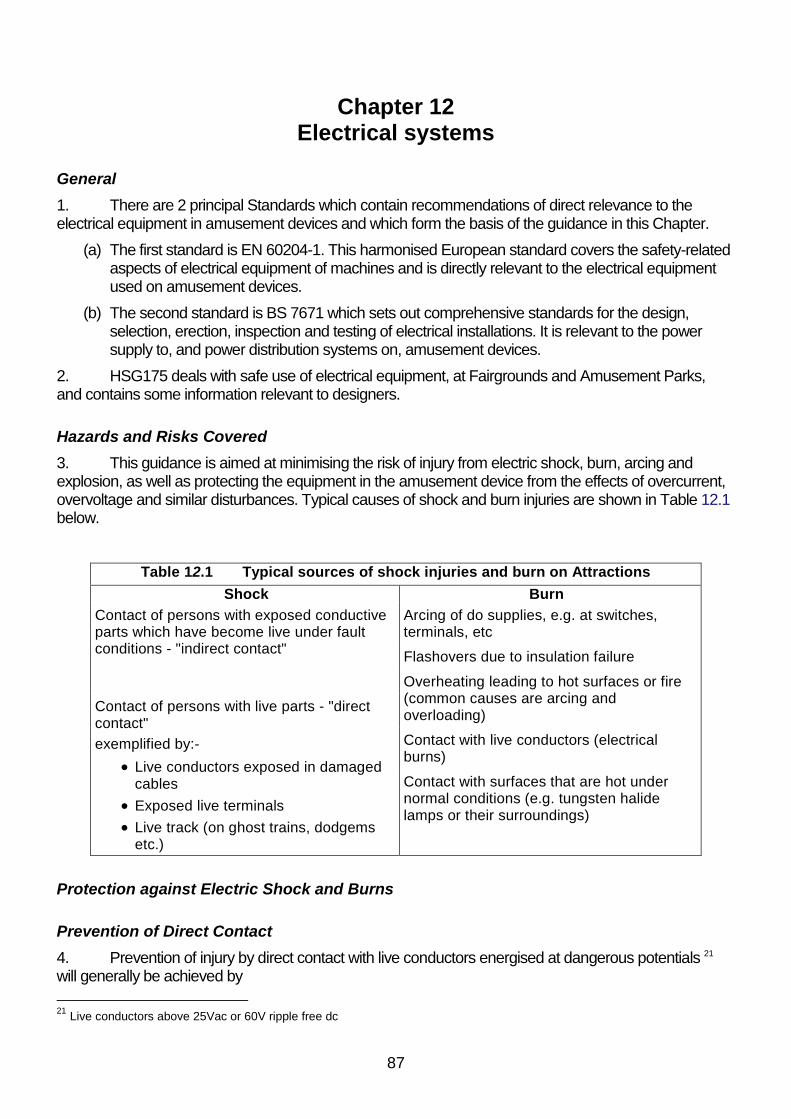
87
Chapter 12Electrical systems
General
1. There are 2 principal Standards which contain recommendations of direct relevance to theelectrical equipment in amusement devices and which form the basis of the guidance in this Chapter.
(a) The first standard is EN 60204-1. This harmonised European standard covers the safety-relatedaspects of electrical equipment of machines and is directly relevant to the electrical equipmentused on amusement devices.
(b) The second standard is BS 7671 which sets out comprehensive standards for the design,selection, erection, inspection and testing of electrical installations. It is relevant to the powersupply to, and power distribution systems on, amusement devices.
2. HSG175 deals with safe use of electrical equipment, at Fairgrounds and Amusement Parks,and contains some information relevant to designers.
Hazards and Risks Covered
3. This guidance is aimed at minimising the risk of injury from electric shock, burn, arcing andexplosion, as well as protecting the equipment in the amusement device from the effects of overcurrent,overvoltage and similar disturbances. Typical causes of shock and burn injuries are shown in Table 12.1below.
Table 12.1 Typical sources of shock injuries and burn on AttractionsShock Burn
Arcing of do supplies, e.g. at switches,terminals, etc
Flashovers due to insulation failure
Contact of persons with exposed conductiveparts which have become live under faultconditions - "indirect contact"
Overheating leading to hot surfaces or fire(common causes are arcing andoverloading)
Contact with live conductors (electricalburns)
Contact of persons with live parts - "directcontact"exemplified by:-
Live conductors exposed in damagedcables
Exposed live terminalsLive track (on ghost trains, dodgems
etc.)
Contact with surfaces that are hot undernormal conditions (e.g. tungsten halidelamps or their surroundings)
Protection against Electric Shock and Burns
Prevention of Direct Contact
4. Prevention of injury by direct contact with live conductors energised at dangerous potentials 21
will generally be achieved by
21 Live conductors above 25Vac or 60V ripple free dc

88
(a) covering the conductors with suitably-rated insulation which is protected against mechanicaldamage, or
(b) by placing the conductors in positions that will prevent them being touched, or
(c) by providing enclosures to prevent access to them.
5. It is foreseeable that access may be gained to any electrical enclosure on an amusementdevice by persons (e.g. operators / attendants) who do not have the required level of competence toensure electrical safety. There are also extra risks, such as falls from height, or restricted accessassociated with the sometimes difficult access to panels on amusement devices which may also affectcompetent persons.
(a) In order to prevent injury by persons touching uninsulated live conductors inside the enclosures,equipment should be designed so that controls and devices which may need to be reset, suchas circuit breakers and motor overloads, are readily accessible without exposing live parts whichmay be dangerous by, for example, putting these switches or controls in a separate enclosurewith no live parts exposed or by using finger proof terminals and fully insulated conductors for allother items in the same enclosure.
6. Suitable measures to prevent direct contact with conductors energised at hazardous voltagesmay include a combination of
(a) components that have finger proof terminals (Ingress protection rating of IP2X as defined in BSEN 60529)
(b) conductors including busbars that are individually sleeved or insulated; or
(c) the placing of non-conducting barriers or shields (perspex, polycarbonate, etc.);
(d) interlocking the door of an electrical enclosure with an isolator so that the door can only beopened when the isolator is off and the isolator can only be turned on when the door is closed.
i. All parts inside the enclosure that remain live after the isolator has been turned off shall beprotected against direct contact to at least IP2X.
ii. The interlock may need to be overridden to allow testing and fault finding work to be carriedout, in which case the following provisions apply:
a. defeating the interlock must only be carried out by electrically qualified personnel with thecompetencies required for undertaking live work; advice on this and the associatedsafety precautions must be contained in the instruction manual.
b. it must be possible for the isolator easily and readily to be turned off while the interlock isdefeated. It is preferable that, in addition, there should be an alternative means ofisolation in the power circuit up stream of the enclosure in which the interlock is defeated.
The above list is not exhaustive and reference may be made to Standards and otherguidance material for further information.
7. If a screen or barrier is used to protect a group or number of items it should be designed in sucha way that the switchgear and control gear that requires manual operation can be operated without theremoval of the screen or barrier.
8. Designers should take steps to prevent foreseeable misuse of electrical equipment by, forexample, providing robust locking facilities on enclosure doors and ensuring that equipment is of robustconstruction.
9. Where devices such as slip rings, live rails and pick-ups allow access to live exposedconductors they should be protected to a minimum standard of not less than IP2X except when rails,

89
conductive floors and ceilings are part of a Protective Extra Low Voltage (PELV) or Separated ExtraLow Voltage (SELV) system.
Protective Extra Low Voltage (PELV) or Separated Extra Low Voltage (SELV)
10. PELV is defined in BS EN 60204-1 and both PELV and SELV are defined in BS 7671.
11. Sources for SELV must not have any connection between the output connections and anyprotective earthing circuit, even accidentally, and must have the maximum voltage restricted to 25 V a.c.or 60 V d.c. with a maximum ripple of 10% rms.
12. PELV sources are also restricted to a maximum voltage of 25 V a.c. or 60 V d.c. with amaximum ripple of 10% rms and they can only be used in dry locations and when large area contact oflive parts with the human body is not expected, unless the maximum voltage is restricted to 6 V a.c. or15 V d.c.
13. PELV sources have one side of the circuit connected to the protective bonding circuit therefore,in circumstances where it is foreseeable that faults may occur which can lead to the protective conductorbecoming energised at voltages in excess of 25 V a.c. or 60 V d.c., SELV systems, are preferred.
14. The electrical risks, and recommended protective measures, associated with the operation ofdodgems where voltages in excess of PELV and SELV are used are discussed in the specific annex.
Prevention of Injury by Indirect Contact
15. Precautions should be taken to prevent injury from exposed metalwork of the attractionbecoming live under fault conditions at voltages and for lengths of time that may cause injury.
16. In a.c. systems this is commonly achieved by providing a system of earthed equipotentialbonding and automatic disconnection of supply (EEBADS). This necessitates coordination between thetype of electrical supply, the earthing system, the impedance of the different elements of the protectiveearthing and bonding system, and the characteristics of the devices such as fuses and circuit breakersused to detect excess of current and automatically to disconnect the supply.
17. Traditionally, many amusement devices with d.c. equipment have been supplied fromgenerators which are not referenced to earth, i.e. where neither pole of the d.c. supply is deliberatelyconnected to earth.
18. Key points for designers of attractions are
(a) There should be a terminal provided on the amusement device where the electrical supply isbrought in to allow the circuit protective conductor from the source of supply to be connected tothe bonding conductors which connect together all exposed conductive parts of the attraction.
(b) The minimum cross sectional area of the protective and bonding conductors should be selectedaccording to the guidance in EN 60204
(c) Metallic structures of attractions and parts of attractions, including items such as pay boxes,chassis and frames, should be electrically connected (bonded) together.
(d) Bolted or similar mechanical connecting methods on the rides and / or structures may be usedto provide continuity of the bonding conductor, provided that these mechanical connectors donot contain any insulating insert and are tight and free of corrosion.
(e) The conductivity of these parts of the ride and / or structure should be verified on initialmanufacture and, if necessary, additional bonding conductors should be provided. Where theelectrical risk justifies it, flexible conductors should be used to connect across discontinuities

90
such as slotted joints, hinges and pins.
(f) Where slip rings are used to transmit power, an earth slip ring should be provided and used;bearings are not suitable for this purpose
(g) Where protective devices such as HRC fuses and circuit breakers are used to provideautomatic disconnection on attractions that use the EEBADS technique, they should beinstalled and rated to ensure that
i. fixed equipment is disconnected from the supply under short circuit and earth faultconditions, in a disconnection time not exceeding 5 secs; and
ii. portable and handheld equipment is disconnected in a time not exceeding 0.4 sec.
(h) The excess current circuit protection should be installed in
i. all phase conductors of referenced a.c. systems;
ii. the live conductor of 2-pole referenced d.c. systems; and
iii. all live conductors of unreferenced a.c. and d.c. systems but not circuit protective conductors.
19. As an alternative to earthed equipotential bonding and automatic disconnection, amusementdevice designers may provide protection by
(a) the use of Class II equipment with double or reinforced insulation; or
(b) the use of electrical separation and PELV / SELV systems.
Residual Current Devices
20. For supplementary protection against electric shock on a.c. systems the designer should specifya residual current device (RCD), with a maximum sensitivity of 30 mA, no adjustable time delay, anddisconnection time not exceeding 40 ms for a residual operating current of five times the sensitivityrating (i.e. for a 30 mA RCD this would be 150 mA) on earth-referenced systems supplied at a voltageexceeding 100 V a.c., which in turn supply:
(a) circuits which are likely to be used to supply portable equipment outdoors.
(b) socket outlets on an amusement device.
(c) theme lighting, although advice should be sought from the manufacturer of the RCD if dimmerand solid state control of the lighting is used since these may interfere with the operation of theRCD. RCD supplementary protection is only necessary where the luminaires are within reach ofmembers of the public or by operators and attendants going about their normal duties.
21. The hazards and risks arising from loss of supply to lighting and motive power, as a result ofdisconnection by unwanted tripping of RCDs should be considered. (see later paragraphs referring toemergency lighting.)
22. More than one RCD may need to be specified to provide discrimination, and in particular toprevent power to the entire attraction being disconnected as a result of a single fault. Discrimination cannormally be achieved by using RCDs with suitable time delays. Each RCD should be:
(a) as close as practicable to the supply of the circuit it protects
(b) easily accessible
(c) easily reset
Protecting systems against fault currents

91
23. Each system and its constituent parts should be designed to withstand without danger theeffects of overcurrent and the maximum fault current which could occur as a result of short circuit orearth faults. Table 12.2 shows the differences between overload and short circuit faults.
Table 12.2 Typical differences between overload and short circuit fault currents
Example for a system with a 240 V ac supply, with cables rated at 30 amps, and amaximum load current of 20 amps
Overload Short circuitLikely cause Too many appliances on
circuit or a stalled motorDirect connection betweenlive-live, live-neutral or live-earth
Magnitude ofcurrent dependsmainly on
Number and rating ofappliances connected or,in the case of the stalledmotor, the circuitimpedance.
For earth faults, the earth fault loopimpedanceFor short circuit faults, the overall circuitimpedance.In both cases, the lower the impedance,the higher the fault current.
Likely effect Slow burnout of circuit –may cause fire
Rapid burnout of circuit–may beexplosive
What to specifyon circuitprotective device
Nominal rating of device tobe between 20 and 30amps.Current causing effectiveoperation of the device tobe less than or equal to43.5 amps (1.45 x 30)
Nominal rating of device to be between 20and 30 amps.Current causing effective operation of thedevice to be less than or equal to 43.5amps (1.45 x 30).Fault breaking capacity (i.e. the currentthe protective device can safelydisconnect) to be greater than theprospective short circuit current.
24. There are two things the designer needs to consider in protecting against fault currents - systemprotection and coordination as described in paragraph 22, and the correct rating of the switchgear,equipment and cables protected.
25. System protection is achieved by specifying HRC fuses and / or circuit breakers to interrupt thesupply if there is a fault or overload. The designer should make sure that both the nominal rating andfault breaking capacity of each protective device are specified and are sufficient for the intended use.
26. The current carrying capacity of switchgear, cables and equipment should be greater than therating of the protective devices on the circuits supplying them. Protective switchgear should be ratedsuch that it can withstand the maximum through fault for either 1 second or 3 seconds, depending uponthe design specification of the installation or system. Note that changing the specification of a cable maynot only change the fault current rating of the installation but, because the earth loop impedance is likelyto be altered, also the value of the fault current itself.
Means of disconnecting (isolating) and functional switching of the supply
27. All attractions should be designed with means to disconnect (isolate) the supply to all liveconductors. Suitable means of disconnection are listed in EN 60204-1. When used for achievingisolation, the disconnecting device should have a means permitting it to be locked in the off (isolated)position (e.g. by padlocks). Also, devices used for isolation must have a visible gap or a positionindicator that conforms with IEC 60947-3.

92
28. Functional switching and disconnection for isolation should apply as a minimum to the followingconductors :
Table 12.3 Disconnection of conductors for isolation
three phase all three phases
three phase and neutral all three phases22
single phase referenced to earth phase and neutral
single phase not referenced to earth both phases
single phase centre tapped both live conductors at the supply and ateach individual consuming unit.
d.c. not referenced to earth positive and negative
d.c. referenced to earth positive
29. Where the means of switching the supply is by way of a plug and socket, the circuit protectiveconductor should make first and break last and the rating of plug and socket should not exceed 16 A.
30. For a.c. and d.c. systems not connected to earth, the means of cutting off the supply must breakboth poles, e.g. if a knife switch is used for disconnection, it must be a double knife. (Domestic switchesare normally single pole only and are therefore unsuitable for this purpose).
31. Each motor circuit should be designed to contain a readily accessible isolator which may beused to cut off power to the motor and all associated equipment, including any automatic circuit breaker.(Not all switches, switch fuses, circuit breakers are capable of being used as isolators.Electromagnetically operated or semi-conductor contactors or motor starters are not isolators).
32. Isolators are needed at :-
(a) the point of supply
(b) other locations where equipment can be conveniently isolated
(c) each item of equipment where it cannot be isolated as a group
33. In considering the location of such isolators, the following should be considered :-
(a) The distance of the isolator away from the motor.
(b) The risk of persons not isolating due to the distance required to get to the isolator.
(c) The risk of persons not isolating due to difficult, or time consuming access to the isolator, suchas when it is located at the bottom of a roller coaster or log flume escalator, when the relevantmotor is at the top.
Ingress Protection class of equipment and components
34. The degree of ingress protection of plugs, sockets, connectors, conduit, trunking, enclosures,fittings and other equipment shall not be less than IP2X when installed in closed rooms or whereprotected from the effects of the weather, although IP44 shall be specified where there is a possibility ofthe equipment and components being subjected to moisture or dust.
35. Equipment and components installed in all other areas should have ingress protection of not
22 Neutral may also be disconnected but it should break after or at the same time as the phase conductor and be remadebefore or at the same time as the phase conductor

93
less than IP65
Protection against effects of lightning, static discharges and switching surges
36. On most attractions no additional provisions for lightning protection are required. However, inthis respect designers should consult BS 6651 or ENV 61024-1 for guidance on how to carry outlightning risk assessments and on precautions that may need to be taken.
37. Some amusement devices suffer from static discharge, as passengers leave or enter thedevice, due to the composition of some types of running gear etc. Normal earthing procedures shouldeliminate this; however it may be necessary to fit extra earthing arrangements to devices such as non-powered roller coasters, that would not normally have any earth connection. Such arrangements mayonly need to be activated immediately prior to disembarkation or embarkation, subject to riskassessment.
38. Where electrical equipment may be subject to transient overvoltages due to switching surges,the designer should consider the need for overvoltage suppression devices to be fitted to the incomingterminals of the supply disconnector.
Generators, rectifiers and transformers
39. Designers of amusement devices need to take account of the nature of the electrical supply tothe device and must provide information to the users of the device on the nature of the requiredelectrical supply and earthing arrangements.
40. Permanent supplies from electricity companies will normally have an associated earthconductor connected to the star point of the company's distribution transformer, either directly or as partof a combined neutral / earth conductor. Provision should be made on an amusement device likely touse external supplies to connect the incoming earth to the device's main earth terminal.
41. On a.c. generators supplying amusement devices, the star point (or neutral) should beconnected to the frame of the generator and the circuit protective conductors and bonding conductorsconnected to the frame. Where practicable, the frame should be connected to earth using suitable earthelectrodes or mats.
42. Small single phase generators rated at less than 5 kVA and supplying single amusementdevices such as bouncy castles via short lengths of cable (less than 10 metres) may be used asunreferenced isolated supplies, provided that the cables are suitably protected against mechanicaldamage and that the exposed metalwork of the amusement device is bonded to the frame of thegenerator.
43. D.C. generators are normally operated as unreferenced supplies, but the protective andbonding conductors for the connected attractions should where possible be connected through to theframe of the generator.
44. Equipment used to provide d.c. supplies should be configured so as to limit the ripple on thesupply to the levels specified for PELV and SELV systems, but see Annex 1 for the requirementsrelating to dodgems.
45. Adequate measures should be provided at the generator output distribution point in order toprotect all outgoing cables against overload and short circuit. Any such protection should take account ofthe actual size of conductors used to supply equipment, and be in accordance with BS7671.
46. Any circuit breaker or fuse device should not have a current rating higher than the ratedmaximum current carrying capacity of any cable connected to that circuit breaker or fuse.

94
47. It should be ensured that the earth loop impedance, of any distribution system or ride feedersystem, is co-ordinated with the associated generator output circuit breaker or fuse, so that themaximum disconnection times required by BS 7671 are not exceeded.
48. Secure mountings should be specified for the generator including, if necessary, anti-vibrationmountings on the generator or immediately adjacent.
49. Adequate ventilation should be specified for enclosures to contain rectifiers or transformers.
50. It is necessary to ensure that there is clearly visible information marked on generators (this mayinclude information necessary to the user e.g. voltage, connection information, minimum cable sizes,correct fuses, maximum load, frequency and earthing requirements).
Motors
51. Motors should be provided with readily accessible means of starting and stopping, including inemergency. Motors driving rides should be fitted with systems to prevent them restarting automatically,either when power is restored after an interruption to the supply or when resetting circuit breakers oroverload protection devices.
Lighting and audio systems
52. All parts of an amusement device around which persons may circulate, including access andegress, should be provided with sufficient illumination to ensure safety, bearing in mind the intendedtimes and locations at which the device may be used.
53. In locations where amusement device controls are to be operated, and in electrical switch-rooms, there must be adequate and sufficient lighting available at all times.
54. Light fittings and speakers should be designed :-
(a) to be securely attached to the structure, battens or support wire intended to carry them, i.e. thesupport structures and the equipment should be sufficiently strong in all foreseeableenvironmental conditions (including wind);
(b) not to rely on electric cable conductors to carry their weight, inclusive of any attachments, unlessthe cable is specifically designed for this purpose;
(c) not to be exposed to moisture unless designed for such exposure;
(d) to be placed out of reach unless precautions are taken to protect against shock and burn (e.g. inthe event of broken fittings leaving filaments exposed);
(e) to be protected against damage in attractions where projectiles are used
Emergency lighting
55. All parts of an amusement device around which persons may circulate, including access andegress, should be provided with sufficient emergency escape lighting, bearing in mind the intendedtimes and locations at which the device may be used.
56. In the case of devices deliberately designed to be operated in dark conditions, emergencyescape lighting should be provided which should comply with BS 5266-1 and EN 1838.
57. If at any time there is a failure of the lighting in a structure containing amusement devices, theparts of the structure affected, including any exit signs, should immediately be illuminated by emergencyescape lighting.

95
58. Emergency escape lighting may be supplied from the same source as the normal lighting, butshould also be capable of being powered by an independent supply. The independent supply should bebrought into operation immediately and automatically in the event of failure of the normal supply.
59. Where batteries are specified as the means of powering emergency escape lighting, thedesigner should provide instructions for checking and ensuring that adequate charge will be available atall necessary times.
60. Any area entered or used by operators or attendants shall be provided with standby and / orescape illumination as above.
Additional requirements for water rides
61. Water rides that use electrical systems such as electrically driven water pumps have thepotential for increased risk of electrical injury and, as a consequence, special precautions must be taken.BS 7671 and its supporting Guidance Note 7 Special Locations provide comprehensive guidance on themeasures that should be taken in locations where the presence of water increases the risk of electricalinjury. Designers of water rides and similar amusement devices should refer to these publications.
Provision of Information about Supply Requirements
62. The following data should be marked on a plate at the point of connection of supply to anamusement device and repeated in the Operations Manual
(a) Minimum / Maximum power requirements
(b) Voltage
(c) If AC, the number of phases, the frequency in Hz, and whether or not a neutral connection isrequired.
(d) Maximum allowable Ze (earth loop impedance at that point).
Relevant Standards and Other Publications
BS EN 1838 Lighting applications. Emergency lighting.
BS EN 60204-1 Safety of machinery. Electrical equipment of machines.
BS EN 60529 Specification for degrees of protection provided byenclosures (IP code).
ENV 61024-1 Protection of structures against lightning. Generalprinciples.
BS 5266-1 Emergency lighting. Code of practice for the emergencylighting of premises
BS 6651 Code of practice for protection of structures againstlightning.
BS 7671 Requirements for electrical installations. IEE WiringRegulations. Sixteenth edition.
HSG 175 Fairgrounds and amusements parks: Guidance on safepractice.
96
Chapter 13Information to be provided by Designers
General
1. So far as the safety of a particular design of amusement device is concerned, the Health andSafety at Work etc Act 1974 (as amended particularly by the Consumer Protection Act 1987), andassociated Regulations, apply in Great Britain. Under section 6(1A) of the Act :-
(a) “ It shall be the duty of any person who designs, manufactures, imports or supplies any article of fairground equipment'23
(b) ... ;24
(c) ...
(d) to take such steps as are necessary to secure that persons supplied by that person with thearticle are provided with adequate information about the use for which the article is designed orhas been tested and about any conditions necessary to ensure that it will be safe and withoutrisks to health at all times when it is being used for or in connection with the entertainment ofmembers of the public; and
(e) to take such steps as are necessary to secure, so far as is reasonably practicable, that personsso supplied are provided with all such revisions of information provided to them by virtue of thepreceding paragraph as are necessary by reason of its becoming known that anything givesrise to a serious risk to health or safety.”
2. The industry associations that endorse this guidance, with the support of the Health and SafetyExecutive, are concerned that the law shall be followed and, to help to demonstrate that it is, they haveput in place some amusement device safety principles which must be followed by their members if theyare to operate in Great Britain. One of the fundamental safety principles is that :
(a) The significant risks associated with safety-related work potentially affecting an amusementdevice are formally checked and thereby require the agreement of an independent party thatthe primary duty holders (designers, in this case) have adequately controlled any associatedrisks.
3. Safety-related aspects of designers' duties are independently checked in a process known as"Design Review". A second fundamental principle relates to those persons carrying out the checks :-
(a) Such individuals, and the firm or business for whom they work (known as an "inspection body"),are required to meet specified competence requirements, including minimum qualifications,experience and training appropriate to the particular types of work for which they claim compe-tence. The details have to be registered annually with an agreed registration body which carriesout a range of appropriate checks on their validity.
4. Then, a third fundamental principle relates to the independence of the inspection body and theirpersonnel from those whose work they are checking :-
(a) The inspection body shall be independent of other parties involved.
23 "article of fairground equipment" means any fairground equipment or any article designed for use as a component inany such equipment.Note also that section 6(1) includes similar duties regarding safety during installation, maintenance etc.
24 Subsections 6 (1A) (a) & (b) have been omitted here for reasons of clarity.

97
(b) The inspection body, and its staff responsible for carrying out the inspection (in this case the"Design Review") shall not be the designer, manufacturer, supplier, installer, purchaser, owner,user or maintainer of the items which they inspect, nor the authorized representative of any ofthese parties.
(c) The inspection body and its staff shall not engage in any activities that may conflict with theirindependence of judgement and integrity in relation to their inspection activities. In particularthey shall not become directly involved in the design, manufacture, supply, installation, use ormaintenance of the items inspected.
5. The industry believes that its commitment to these 3 principles - of double-checking, registrationof competence of those carrying out checks, and independence from conflicting influences on theirchecking work - helps to ensure greater public safety.
6. Where a design combines a number of different disciplines and / or persons, any personcommissioning design work, or any person who imports, should appoint a design project safety co-ordinator (which may be himself if he has appropriate competence) and inform the relevant parties inwriting. That person should check the way in which the elements combine and should ensure that everysafety-related aspect has been covered.
7. In order for the necessary checks to be carried out and for controllers of amusement devicesand their staff to be able to maintain and operate their equipment in a way which ensures safety,appropriate documentation must be made available. This needs to be in English and the language ofthe controller. The main elements of this should be as follows below:
Information to be used in Design Review
8. Designers need to make technical information available to enable Design Review to be carriedout. More details about this process may be found in a sister publication25 but it should be noted that theinspection bodies carrying out this work are required to ensure confidentiality of commercially-sensitiveinformation which does not need to be divulged for safety reasons.
9. The information that needs to be passed on to the amusement device controller should beincluded but needs to be supplemented by the following more specialised technical information :-
(a) design risk assessment documentation (see Chapter 1);
(b) assessments, or checks that have been carried out, relating to functional safety, installation,testing, commissioning
(c) details of any modifications to the original design together with details of checks that have beenmade regarding such modifications;
(d) information on the correct configuration of equipment and computer systems;
(e) description and relevant up-to-date drawings of the components used, how they should becorrectly assembled and the correct setting of adjustable features;
(f) instructions for installation and commissioning;
(g) instructions provided for the user which specify the actions necessary to maintain safety duringoperation and maintenance, including details of when operational and proof checks should bedone;
25 Safety of amusement devices: Inspection; to be published by ADSC on behalf of the industry associationsendorsing the British guidance documents (i.e. ACES, AIS, ALES, BACTA, BALPPA, SGGB, SIRP, NAFLIC) inpartnership with the HSE.

98
(h) in-service NDT schedules based on calculated fatigue lives (NDT schedule);
(i) information on possible fault conditions and their significance for safety.
Information to be used by the controller in the Operations Manual
Information on design and manufacture
10. The manual needs to contain certain specific information on design, including:
(a) a summary of salient safety features;
(b) a summary of design and required manufacturing standards (materials, quality control, etc);
(c) the design specification, including, where possible:
i. the grade and dimensions of any bolts, screws and rivets whose failure could cause danger;
ii. specifications and manufacturers' names for proprietary assemblies such as motors, gearboxes, pumps, hydraulic cylinders, etc.
Relevant drawings or diagrams
11. The manual needs to contain relevant drawings or diagrams, including:
(a) outline drawings, showing the main dimensions of the device when assembled and therecommended safe clearance distances when in motion;
(b) a plan showing the weight distribution and recommended packing points, together with themaximum permitted load at each point and any foundations required;
(c) the interrelationship of regularly assembled parts, with each part identified by a unique numberwhere appropriate;
(d) diagrams of all control systems (hydraulic, pneumatic, electrical) according to ISO standardstogether with program listings, etc, for all programmable and non programmable electronicsystems (PLCs, drive parameters, etc).
Replacement parts
12. The manual needs to contain a full list of replacement parts and their reference numbers.
Information on transport, installation, erection, dismantling
13. The manual needs to contain information on transport, installation, erection and dismantling,including:
(a) diagrams to show the correct assembly of the component parts;
(b) a key to the identification of non-interchangeable parts;
(c) information on the correct use of any special equipment required for assembly;
(d) procedures for setting up and dismantling the device correctly including, where relevant, detailsof:
i. any safe systems of work required;
ii. advice on ground or foundation preparation;
iii. order of assembly / disassembly of component parts;

99
iv. any temporary measures needed to support a partially completed device;
v. torque settings essential to the safety of screws or bolts;
vi. any procedures needed to prevent or relieve stress concentration during assembly /disassembly;
vii. jacking and packing points and procedures, including selection of materials, load spreadingand ballasting where relevant;
viii. levelling and out-of-level tolerances;
ix. physical guards, barriers, fencing, etc;
x. mechanical and electrical power requirements;
xi. correct methods for connecting electrical equipment to the power supply;
xii. grounding for lightning protection;
(e) the following data regarding electrical requirements, which should be identical to that marked onthe plate at the point of connection of supply to an amusement device :
i. Minimum / maximum power requirement
ii. Voltage
iii. If AC, the number of phases, the frequency in Hz, and whether or not a neutral connection isrequired
iv. Maximum allowable Ze (earth loop impedance at that point).
(f) any checks or testing needed to make sure the device has been assembled correctly and isfunctioning in the intended manner.
Information on safe use
14. The manual needs to contain information on:
(a) safe use, including:
i. a description of the normal functioning of the device (including the function and motion of themajor components);
ii. the normal safe operating procedure (including the functions and responsibilities of theoperator and attendants);
iii. details of operating speeds. The maximum or limiting speed should not be based solely onthe forces that the device can withstand but should also take account of the need to preventinjury to users;
(b) loading which should specify:
i. the maximum working loads;
ii. maximum passenger numbers;
iii. permissible out of balance loading;
iv. order of passenger loading;
(c) limitations to use, e.g.
i. passenger dimension (size, weight), medical condition,

100
ii. adverse environmental conditions (particularly wind speed);
(d) details of any passenger containment system and guidance on its use;
(e) information on relative positioning of passengers in the same car;
(f) detailed explanation of the controls and their function;
(g) safe passenger access;
(h) limitations required to prevent overload of the structure in waiting areas;
(i) faults and fault finding, including indications of malfunction and the action to be taken;
(j) emergency procedures.
(k) evacuation procedures.
Instructions and guidance on any maintenance and inspection
15. The information needs to cover:
(a) components which require regular lubrication including information on suitable lubricants andthe frequency required;
(b) components which require regular replacement and the period between replacement;
(c) components which require inspection for wear and fatigue, correct setting etc, together withdetails of the correct settings and allowable tolerances;
(d) electrical equipment together with any checks to be done by the user and details of safeisolation procedures;
(e) maintenance and testing of controls and interlocks.
Information relating to Examination and testing of the device once in use
16. Safety-critical components need to be identified and estimates given of their likely life. It isimportant that the documentation is adequate (e.g. by the inclusion of drawings or photographs) toidentify the safety-critical regions of these components to those who will subsequently have to inspectthem.
(a) Inspection or examination intervals need to be specified as well as the type of techniques to beused, e.g. visual or NDT, and criteria for acceptance / rejection.
(b) Where appropriate reference material relating to the original condition can be included, e.g. theresults of original NDT or measures of the performance of safety-critical components orsystems. Guidance should also be given on the parts which should be covered by the daily andother periodic checks.
17. A NDT schedule should be prepared by the designer, which should take account of calculatedfatigue lives, revised in the light of information received from inspection, testing, operation, etc. Forfurther information see Chapter 4.
18. It is important to record as much information as possible about the original as-built condition ofthe device for two principal reasons.
(a) Firstly, such information can be critical to the accuracy of initial design assumptions and it is vitalthat this information is fed back to the designer and design reviewer so that the accuracy ofthese assumptions can be checked.

101
i. Any necessary alterations to, for example, fatigue life assessments and consequent NDTschedules can then be implemented (eg. as a result of unexpected secondary accelerationscaused by variations in accuracy of a ride track or play in rotating elements, etc).
(b) Secondly, it provides a benchmark of the condition of the device, which is vital for futureinspections in terms of determining the amount of wear, degradation of components, etc (e.g.the amount of play in slewing rings, bearings, bushes, etc, under prescribed, repeatable testconditions, the settings of adjustable parameters, etc).
i. It is important that this information is considered in relation to the design parameters andassumptions, its significance to those parameters and assumptions is carefully assessedand the designer alters any information they need to provide accordingly. Any such alterationto this information also needs to be subject to Design Review.

102
Appendix 1Common amusement device hazards
1. The following Table A.1 lists some of the more common hazards associated with fairground andamusement park machinery and structures.
2. The right hand column indicates Chapter numbers in this publication which contain text relatingto the particular hazard.
3. Chapter 1 explains the process by which risk assessment associated with a particular hazardshould be carried out.
4. The Table is not claimed to include every amusement device hazard that may exist, nor doesthis publication address all of those listed. The designer should identify any additional significant hazardsfor risk assessment in accordance with Chapter 1.
Table A.1 Some hazards associated with amusement devices
Hazards Refer to Chapter
Falls of persons (also slips and trips)
On flat (e.g. poor surfaces, inadequate lighting) 11
From one level to another 11
Persons (including employees and bystanders) struck by falling or ejected objects
Passengers' belongings
Mechanical / structural or other parts coming unfastened or failing inservice (including backdrops, scenery, light fittings, speakers) 4,6
Tools
Ejected passengers / employees 2,10
Persons (including employees and bystanders) struck by other objects
Airgun pellets
Arrows / darts
Other projectiles
Hazards arising from raised anxiety states affecting vulnerable persons
Persons with heart problems
Pregnant women
Mentally impaired passengers
Hazards arising from forces of motion on passengers
Nausea 2
Physical damage resulting from intensity, direction and duration ofaccelerations and jerks (i.e. change of accelerations) 2,10
Hazards associated with passenger containment
Ejection of passenger 2,10
Effect of forces exerted by elements of containment 2,10
Movement of passenger unit while loading / unloading 8,9
Hazards from impact/ collision

103
Table A.1 Some hazards associated with amusement devices
Hazards Refer to Chapter
Collision of passenger unit with pedestrians (land trains etc.)
Collision of passenger unit with structures
Collision with another vehicle (e.g. Dodgems, multiple unit rollercoasters)
9
Hazards from motion relative to, contact with, or proximity to, machinery
Squeezing / crushing 10
Cutting / severing 10
Shear traps 10
Entangling (including ride passengers' hair and clothing)
Struck while moving / reaching into or out of 11
Asphyxiation / poisoning / nausea etc. from contact with or inhalation ofdust, fluids, gases, mists, fumes, vapours
Burning by high temperature surfaces 11
Electric shock 12
Hearing or other damage from high noise levels
Positional instability of amusement device including wind effects
Overturning (including the possibility of inadequate foundations orpacking) 6
Sliding off packing 6
Lifting off 6
Structural / mechanical breakage
Static failure following from :-
Loadings not properly accounted for; including overloading, excessive out-of-balance loading, wind and snow loading (earthquake not relevant inUK)
3,6
Calculation error
Fatigue failure following from :-
Inadequate dynamic analysis or stress analysis 2, 3, 4
Structural / mechanical vibrations unaccounted for 2
Secondary dynamic effects unaccounted for 2
Inspection regime not consistent with calculated fatigue life 4
Failure or seizure as a result of wear, corrosion or rot
Escape of liquids / gases under pressure (hydraulic / pneumatic systems)as a result of poor design or in-service deterioration 7
Hazards associated with electricity
Electric shock or burn by direct contact with live parts 12
Electric shock or burn by contact with parts which have become live underfault conditions 12
Arcing 12
Static discharge 12

104
Table A.1 Some hazards associated with amusement devices
Hazards Refer to Chapter
Explosion 12
Lightning strike 12
Fire risk 12
Hazards associated with controls / control systems
Over/under speed 9
Inadequate braking 8,9
Excessive braking 8,9
Inadequate operational, safety, or emergency stops 9
Insufficient safety integrity 9
Software errors 9
Over-reliance on operator / attendant judgement or skill
Unauthorised tampering (e.g. resetting by staff, access by members ofpublic)
8
Hazards due to poor use of ergonomic principles (operators / attendants)
Resulting from :-
Inadequate design, location or identification of manual controls 8
Inadequate design or location of visual displays 8
Insufficient visibility of significant parts of the device from operator /attendant position
8
Inadequate local lighting 12
Excessive physical effort
Effect of exposure to noise (e.g. music)
Noise interference with speech communication, acoustic signals etc.
Additional hazards associated with water (ponds, pools, log flumes, water parks, rapids rides)
Drowning of member of public
Biological or microbiological (e.g. viral or bacterial) - water quality
Hazards associated with underwater maintenance and inspection
Hazards associated with use of electricity 12
Additional hazards associated with crowds
Crushing due to crowd pressure
Emergency situations
Fire 11
Evacuation of members of public from enclosures (including issues suchas lighting, pinch points, etc.) 11,12
Evacuation of passengers from remote locations (e.g. following ridebreakdown) 11

105

106

- 107 -
Appendix 2Electrical safety of dodgem rides
Introduction
1. This appendix provides design guidance on the electrical safety of dodgem rides supplied in theUK. The electrical safety features of this type of ride are unusual because of the characteristic largeareas of exposed live conductors on the floor and the net which are normally, respectively, the negativeand positive poles of the d.c. supply to the dodgem cars. The main complication is that the power andcurrent requirements of the cars, and the need to keep current-carrying cable sizes to manageabledimensions, are such that it is not feasible to restrict the supply voltage to a maximum of 60 Vd.c. Thesupply therefore cannot satisfy the SELV or PELV requirements that apply to other types of ride thatfeature exposed live conductors.
2. It is accepted that dodgem rides may be supplied at voltages exceeding the recommendedlimits for other fairground devices with exposed live conductors. However, in the light of this, care mustbe taken to ensure that users and operators of the rides and other members of the public are notexposed to unacceptable levels of risk of electrical injury. This guidance explains how this can beachieved for rides supplied from 2 types of power source; firstly, a transformer / rectifier unit and,secondly, a d.c. generator.
Basic Principles
3. A generalised configuration of a dodgem ride is shown in Figure A2.1, which is an elevationdrawing showing the floor, net and support structure. In most modern ride designs the support structureis metallic, typically steel poles or lattice towers, and is electrically connected to the floor of the ride, asillustrated in the diagram. Older rides may have support structures made of wood or other insulatingmaterial.
Figure A2.1 Basic Configuration of Ride (in elevation)
4. The overriding design requirement for the d.c. supply to the ride is that its mean value must notexceed 110 V and that its peak value taking account of ripple must not exceed 120 V. This voltage isgenerally recognised to be sufficiently low to prevent serious or irreversible electrical injury (shock andburn injuries arising from current flowing through the body) in dry conditions for the large majority ofpeople. This is reinforced by the history of accidents on dodgems–in essence, there is no evidence that

- 108 -
the presence of large areas of exposed conductive parts energised at this voltage has led to injury fromelectric shock or bums.
5. In addition to restricting the voltage in the way described, the risk of injury from simultaneouscontact between the floor and the net can be further reduced by ensuring that distance D1 in FigureA2.1 is as high as possible; typically, it will be in the order of 2 metres. Furthermore, direct contactbetween the 2 poles of the d.c. supply should be prevented by constructing the ride in a way that makesit difficult for persons to climb the vertical metallic members and reach over to the net.
6. On some designs of car it may be possible to contact opposite poles of the supply whilst in thecar, for example by reaching under the dashboard and touching the positive connection to the motorabove the front wheel whilst also touching metalwork which is at negative potential. This should beprevented by either insulation of the connection or by physical barriers.
7. Measures must also be taken to ensure that the power collectors on the top of the insulatedpoles on the cars cannot bridge the gap between the net and the metallic structure. If this happens,considerable arcing can occur, creating molten spatter that can cause thermal burn injuries to peopleusing the ride. This can be prevented by ensuring that distance D2 is greater than the length of thecollectors or by providing an insulating barrier between the net and the supports.
8. The design of the car should be such that it should not be possible for the pole to becomedisplaced, so that a short circuit at the base of the pole is not possible. Such incidents have been knownto happen, causing burn injuries to the riders.
Rides supplied from transformer/rectifier units
9. The general configuration of this supply arrangement is depicted in Figure A2.2, which illustratesa Class I transformer / rectifier unit fed at low voltage. The Figure excludes the start, stop and othercontrols for the ride. Most units of this type will be supplied at 400 V a.c. 50 Hz 3 - phase from a TNsource, as shown. For clarity, later diagrams will show single phase supplies, but the safety principlesapply to both three phase and single phase supply arrangements.
10. The supply into the transformer rectifier assembly must be configured as either a TN-S source,as depicted, or a TT source for the reason described later in this section.
11. It will be noted that Figure A2.2 incorporates a 'dotted' earth symbol. This has been included toshow that in many applications there will be a fortuitous connection of the metallic structure to earthbecause the structure may be standing on the ground. For this reason, the d.c. supply to the ride shouldbe configured as an isolated supply, meaning that there should be no deliberate connection of eitherpole at the point of supply on the secondary side of the transformer to a reference point, including earth;this includes the metal casing of the assembly. This will prevent return current flowing back to thetransformer secondary windings through fortuitous earth paths.
12. In normal operation the configuration shown in Figure A2.2 will be safe. However, additionalfeatures are required to take account of foreseeable faults that may occur and which may lead todanger.

- 109 -
13. Multiple connections may be used to both the net and to the track to ensure equipotential.However, the cross-sectional area of each of the individual conductors should be equal to the mainsupply cable.
FigureA2.2
General
arrangement of transformer/rectifier unit supplying a ride
14. Overcurrent protective devices should be inserted in both poles of the supply on the secondaryside of the transformer to cater for conditions where excess of current will flow. This may include, forexample, faults in the car motors and a short circuit fault between the net and the floor or supportstructures.
(a) The prospective short circuit current from the transformer will often be lower than the currentcarrying capacity of the cables connected to the ride, but means still need to be taken to protectagainst excess current flowing for extended periods of time.
(b) The rating and tripping characteristics of the overcurrent devices should be selected to takeaccount of the maximum prospective short circuit current and factors such as stalled motorcurrents that will flow into the motor loads at start up and during stalled conditions.
15. In those cases where the transformer assembly is not constructed to meet the safety isolatingtransformer requirements set out in EN 60742 there is the possibility of inter-winding faults that maycreate a conducting path between the primary and secondary windings of the transformer.
(a) This would lead to dangerous a.c. voltages being present on the exposed conductive andaccessible parts of the ride. To reduce the risk of danger from this type of fault, the exposedmetalwork of the floor and support structure should be bonded to the exposed metalwork of thetransformer / rectifier unit which, in turn, should be earthed by the protective conductor of theexternal supply.
(b) Note that this reinforces the need to ensure that no connection is made between the secondaryside of the transformer and the casing of the unit–if such a connection were to be made, aproportion of the return current would flow through the bonding conductor and any earth pathsthat may exist.
(c) The cross sectional area of the bonding conductor should be at least half the cross sectionalarea of the d.c. cables supplying the ride.
16. In those circumstances where the transformer does satisfy the requirements of a safety isolatingtransformer, the bonding connection should still be made.
17. The configuration described in the foregoing paragraphs is depicted in Figure A2.3.

- 110 -
Figure A2.3 Recommended basic configuration26
18. In many circumstances there will be theme lighting and other equipment attached to the ride'ssupport structure, as depicted in Figure A2.4.
(a) Preferably, the supplies to this equipment should be SELV but, where they exceed extra lowvoltage (as exemplified in Figure A2.4 for equipment supplied at 230 V a.c.), alternativeprecautions against both direct and indirect shock must be taken.
19. It is preferable for the equipment to be of Class II construction.
(a) Where the equipment is Class I with exposed conductive parts, there should be asupplementary bonding conductor connected between those parts and any metallic parts on thestructure of the ride.
(b) The bonding conductor should be the same size as the protective conductor on the supply tothe equipment.
(c) Lighting and other electrical equipment supplied with a.c. power, other than lighting provided toilluminate the ride for safety reasons (e.g. emergency exit lighting), should be protected by anRCD, or combination of RCDs, rated to trip at a residual operating current of 30 mA.
FigureA2.4
Recommended configuration with Class 1 apparatus installed on structure
20. This configuration of earthing and bonding means that the a.c. supply to the transformer mustnot be of the TN-C-S variety (also known as protective multiple earthing, PME, with a combined neutralearth, CNE). This is because an open circuit neutral fault on the supply could lead to the ride's exposedconductive and accessible parts becoming live at the supply's phase voltage, which would be adangerous condition. For this reason, the supply must be either TN-S, as depicted, or TT.
21. Where a TN-C-S supply is provided by, for example, a power distribution company, thesupplier's earth must not be used as the main earth connection to the ride, in which case a local earthelectrode should be used as the main earth. In these circumstances, the supply to the transformer /rectifier assembly should have earth leakage protection installed in addition to the usual excess currentprotection.
26 For clarity, this and later diagrams illustrate a single phase supply to the transformer assembly; in most cases the supply willbe 3-phase.

- 111 -
Rides supplied from generators
22. The general configuration of this supply arrangement is depicted in Figure A2.5, which illustratesthe dodgem ride being supplied directly at 110 V dc from a d.c. generator set. The figure does notillustrate any of the control devices needed to operate the ride.
23. The d.c. source should be operated as an isolated supply, with no deliberate connectionbetween the windings and the frame of the generator. This prevents the flow of return current throughearth paths. The only other main precaution is the provision of overcurrent protection in both poles of thesupply–this is normally in the form of fuses or thermal overloads.
24. Although not essential, it is advisable to connect a bonding conductor between the live floorplates of the ride and the frame of the generator. The bonding conductor should have a cross sectionalarea at least half the cross sectional area of the d.c. cables supplying the ride. The main purpose of thisis to maintain the floor and support structure at the same potential as the generator's frame.
Figure A2.5 General arrangement of ride supplied directly by d.c.. from generator
25. Where the design of the ride incorporates theme lighting and other electrical equipment,precautions must be taken against direct and indirect shock injuries. Preferably, the supplies to thisequipment should be SELV but, where they have to exceed extra low voltage for sound engineeringreasons, alternative precautions against both direct and indirect shock must be taken. The bondingconductor connecting the exposed metalwork of the a.c. equipment to the structure of the ride should bethe same size as the a.c. system's protective conductor
26. Class II equipment is preferred, but Figure A2.6 illustrates the situation where an item of Class Iequipment such as theme lighting is supported on the metallic structure of the ride. This equipment issupplied at 230 Vac from a separate a.c. generator. In this case, the a.c. supplies are referenced toearth and to the a.c. generator frame, so the a.c. generator supply must be treated as a TN source.

- 112 -
Figure A2.6 Dodgem supplied from d.c. generator with theme and other equipment supplied from a.c.generator (other than SELV and PELV supplies)
27. In some cases the a.c. and d.c. generators are mounted in the same generating set in a so-called piggy-back configuration. In these circumstances the frames of the d.c. and a.c. sets areelectrically bonded together. An insulation failure between the windings of the d.c. generator and itsframe can lead to d.c. fault current flowing through the bonding conductor and the a.c. system'sprotective conductor, as depicted in Figure A2.7. For this reason, in such piggy-back configurations, thebonding conductor and the protective conductors must be sized to carry the maximum prospective faultcurrent of the a.c. or d.c. system, whichever is the larger
Figure A2.7 Dodgem supplied from d.c. generator with theme and other equipment suppliedfrom ‘piggy-back’ a.c. generator, illustrating fault current flowing in the event of winding-to-frame fault on the d.c. set
Coin ejection mechanisms
28. Many dodgem rides have automatic token mechanisms in the cars. These incorporate amechanical latching arrangement that maintains the token on a switch for the duration of the ride. Thetoken is then ejected at the end of the ride, commonly by a momentary reversal of the polarity of the d.c.supply.
(a) From an electrical safety perspective, this facility does not present any additional hazards so

- 113 -
long as the earthing and bonding arrangements are not affected by the temporary polarityreversal. Where this type of coin ejection technique is used, no other equipment should sharethe same d.c. supply as the dodgem track.

- 114 -

- 115 -
Appendix 3Variations from EN 13814
1. The following text provides some explanation of supplementary safety provisions in GreatBritain in addition to those contained in the European Standard EN 13814 - "Fairground andamusement park machinery and structures - safety".
2. The original proposals for revisions to the text of EN 13814, submitted by BSI in 2000,numbered approximately 128, of which about 57 were either adopted wholesale or dealt with in otherways in the final Standard dated December 2004. Unfortunately, there remain some serious issues. Forinstance, we believe there are cases of "requirements" which :-
(a) include matters which are not permitted in or consistent with other EN Standards;
(b) could be insufficiently safe, unsafe or dangerous; or
(c) break British or European law.
3. While we are pleased that the Standard has been published and that much of it is satisfactory,we have identified the following main points of objection which will necessitate additional or differentsafety measures to be followed for amusement devices that are to be used in Great Britain27
4. The Standard includes many references to types of inspection, approval, etc. which areinconsistent with current practice in Great Britain.
5. A consequence of the current state of the text is that compliance with the Standard would notnecessarily be sufficient to satisfy British expectations. It is our view that designers etc. would need tofulfil additional conditions or variations imposed by ADIPS (the Amusement Device InspectionProcedures Scheme), the Health and Safety Executive's publication HSG 175, and this ADSCpublication. Indeed, the amusement industry associations in Great Britain expect these to be followed.We consider that paragraphs numbered 3.2 - 3.7, 5.1.1, 5.1.4.2, 6.4.2.4.3.2, 6.4.2.4.3.3, 6.5, 6.6, 7 andAnnex H may in some aspects conflict with or be insufficient to satisfy British expectations in thisrespect.
6. It has been British practice for over 20 years to expect that fatigue life assessments ofcomponents are to be carried out by designers. Unfortunately, EN 13814 does not require the designerto pass on any information regarding fatigue lives exceeding 35000 hours, nor to cross check thatinspection / maintenance instructions are consistent with any of the calculated lives. We believe that thiswould be inconsistent with Section 6 of the Health and Safety at Work, etc., Act 1974. Indeed in relationto assessment of risks affecting workers (in contrast to the public), on which the European Union hascommon requirements, we believe that it would also break the law in the other member states.
7. For this and related reasons we consider that paragraphs numbered 5.6.1, 5.6.3 (includingTable 6), 6.4.3.1.4 and Annex A may in some aspects conflict with British requirements, and dutyholders would need to carry out fatigue life calculations for all safety-related components and, for each ofthose which are seen to have a life which is shorter than the maximum anticipated lifetime of the device,prepare maintenance and inspection schedules which are consistent with the results, including details ofmethod and frequency that each procedure is to be carried out. Please note that there is a requirementin Great Britain for a written inspection / NDT schedule, often produced in tabular form for clarity, to be inplace in the Operations Manual. Paragraphs 1 - 9 of Chapter 4 above are relevant.
8. Great Britain has recently introduced specific electromechanical safety advice for dodgemswhich covers some issues not addressed in EN 13814. We therefore consider that paragraph
27 Note that if, as a duty holder, you follow the steps outlined here in addition to EN 13814 you will normally be doing enough tocomply with British law. If you do otherwise you will need to demonstrate and justify equally effective compliance.

- 116 -
numbered 6.2.4.1.6 may in some aspects conflict with or fail to satisfy British expectations. Duty holdersshould refer to Appendix 2 above for more information.
9. EN 13814 now contains several references which tell the designer to apply partial safety factorsfor ultimate limit states even when carrying out fatigue life assessment. This is inconsistent with otherStandards (e.g. EN 1993-1-9) and may result in underestimates of fatigue lives, onerous inspectionregimes or, if re-design is carried out, unnecessarily heavy structures. We therefore consider thatparagraphs numbered B.1.1, B.2.1 and B.3 may in some aspects conflict with British expectations. Inaccordance with British and European Standards covering fatigue (see, for instance, those listed inChapter 4 above), input loads need not be factored when calculating fatigue lives and preparingassociated inspection schedules.
10. Great Britain has recently updated and extended safety advice for amusement device electricaland control system design safety. We therefore consider that Annex D may in some aspects conflictwith or fail to satisfy British expectations. Duty holders should refer to Chapters 9 and 12 above for moreinformation.
11. British requirements for the assessment of design safety of passenger containment are moreextensive than those in EN 13814. (For instance, there have been recent prosecutions of duty holdersfor not making proper use of anthropometric data in assessing safety). We therefore consider that 6.1.6and Annex E (which is, in any case, only "informative") may in some aspects conflict with or fail to satisfyBritish requirements. Duty holders should refer to Chapters 9, 10 and 11 above for more information.These contain, amongst other things, anthropometric data associated with common passenger heightlimits. Such data, arranged by height, is not available in European or ISO Standards and is commonlymiscalculated by designers.
12. It is also the British view that passenger reach distances, as required in the standard, do nottake sufficient note of available anthropometric data and should be increased accordingly. The existingvalues will not prevent passenger’s extremities from coming into contact with external objects(passenger clearance envelope)
13. Unlike earlier draft versions of EN 13814, there is no longer any reference to the need for designrisk assessment to be carried out (formerly in a paragraph then numbered 6.1.3, immediately following6.1.2, now deleted; see also Annex 1). Failure to do this assessment conflicts with British regulations.Indeed in relation to assessment of risks affecting workers (in contrast to the public), on which theEuropean Union has common requirements, we believe that it would also fail to meet the law in theother member states. Design duty holders would need to ensure that a design risk assessment iscarried out. This should form part of the package supplied to the ADIPS - registered inspection bodyresponsible for its Design Review.
14. Paragraph 6.3.8.2.1.6 specifies safety factors for ropes and chains which are much smaller thanthose recommended by the Machinery Directive (98/37/EC). Although the Directive and relatedRegulations and ACOPs will not apply in many cases it may in some. Duty holders would need toconsider whether to apply the larger safety factors.
15. In addition to these broad difficulties, we are aware of a number of specific details in EN 13814(e.g. formulae) which we believe to be incorrect and which could lead to lack of safety. We identify thefollowing :-
16. Wind loading (5.3.3.4.1) - British designers, inspection bodies, etc. are already expected toassess structural shape factors in accordance with BS 6399-2 and EN 1991-1-4. Figure 1 in EN 13814is not consistent with either of these or with any other European or ISO Standard, so far as we canascertain. Shape factors which accord with BS 6399-2 or EN 1991-1-4 should be used.
17. The third paragraph of 5.4.3.5 contains unsafe recommendations about when anti-rollback

- 117 -
devices may be dispensed with. Duty holders will need to assess whether the rollback of a roller coastercar or train through the station can be accomplished with minimal risk to passengers and others in thestation area before omitting safety devices against running back.
18. The second paragraph of 5.7.3 does not deal with all the safety issues of which we are awarerelating to open hooks. That is to say that, in the absence of other justification, the risk assessmentshould assume that in-service primary failure of a member having an open hook termination will lead tounhooking. The consequences of striking or spearing passers-by etc. should be considered.
19. Paragraph 6.1.4.5 does not deal adequately with all the known hazards associated with fencesand railings having horizontal members. The following objectives should be satisfied where anassociated unacceptable risk might result :-not permitting climbing (up, under or through); and notpermitting trapped heads
20. Paragraph 6.1.6.1.7 no longer (compared with earlier drafts of the Standard) warns the designerabout the risk of entrapment of body parts between the outside of the passenger containment and anyobject. Nor is there any mention of this in the subsection 6.1.6.1. It is our view that this will lead to agreater number of unsafe interpretations of the Standard and some non-compliance with Regulation 11of the Provision and Use of Work Equipment Regulations 1998. Unguarded clearance distances in theStandard may be unacceptable for use in Great Britain where dangerous shear traps, etc., have notbeen removed. Duty holders should take account of Chapter 11 above or take other equally effectiveprecautions to ensure compliance with British law.
21. Paragraphs A.4.2 and A.4.3 contain incorrect formulae numbered A.24 and A.31 which couldresult in unsafe results. Calculations involving these formulae will not be acceptable. Since thecalculation of "equivalent constant amplitude stress range" is not a necessary step in the determinationof fatigue life, we do not propose the use of any alternative formulae.
22. Annex G, which in any case is only an informative annex, has some remaining unresolvedproblems which could be unsafe. Duty holders should therefore be aware that compliance with thisannex will not automatically imply that safety requirements have been satisfied.
23. For help in complying with British requirements, inspection bodies registered to carry out DesignReview may be contacted.

- 118 -
Leave blank

- 119 -

- 120 -
IndexAacceleration 20, 21, 22, 31, 56, 76ADIPS 1, 9, 18, 123, 124aluminium 31, 35, 37, 39, 41, 43, 44analysis 13, 14, 15, 20, 21, 23, 26, 31, 32,38, 47, 56, 59, 61, 62, 67, 111ancillary equipment 42article of fairground equipment 104Assessment of fatigue 3, 31audio systems 101
Bball and socket48barriers 3, 17, 25, 77, 91, 94, 107, 116Big Wheel 91block-zone 53, 71, 72bracing loads 25burn 93, 101, 111, 112, 116
CCalculating loadings 3, 25centre of rotation 21Common amusement device hazards 3, 110control modes 68, 69control panels 52control systems 3, 9, 53, 54, 56, 57, 58, 59,60, 61, 62, 63, 67, 71, 74, 82, 83, 106, 112controls 21, 51, 52, 94, 101, 108, 109, 112,116Controlsgeneral requirements 3, 51Coriolis21Coriolis accelerations 21couplings 47, 48
Ddegrees of freedom 21Design Review9, 104Design risk assessment 3, 8Design Risk Assessment (DRA) 8Designing foundations, supports and structures
3, 41differential calculus 21differential equations 21
displays 42, 52, 112documentation 14, 105, 109
Dodgems 111dynamic 3, 20, 21, 22, 25, 26, 27, 28, 42,77, 78, 82, 111dynamic analysis 3, 20, 25, 111dynamic loadings 25, 26, 82early mortality failures 15
EElectrical safety of dodgem rides 4, 115electrical systems 102Electrical systems 3, 93emergency lighting 97, 102emergency stop function 64EN 1050 18environmental 26, 41, 51, 72, 73, 101, 108error estimation 21
FFairgrounds and Amusement Parks –Guidanceon Safe Practice (HSG175). 9fatigue 3, 20, 21, 22, 25, 26, 31, 32, 33, 34, 35,37, 38, 42, 44, 48, 81, 82, 106, 109, 111, 123,124, 125fault currents 97, 98fencing3, 91, 107floors 25, 95forces 20, 21, 22, 26, 28, 41, 46, 48, 66, 70, 76,78, 79, 80, 81, 82, 83, 108, 110foundations 3, 41, 42, 44, 106, 111
Ggenerators 95, 100, 101, 119, 120geometric stress range 31guards 3, 17, 56, 74, 91, 92, 107
HHazard8hot spot stress range 31HSC13REV1 18HSG 175 9, 10, 18, 103, 123Human reliability analysis techniques 13hydraulic systems 46
IInformation on design and manufacture 106Information on safe use 108Information on transport, installation, erection,dismantling 107

- 121 -
Information relating to Examination and testing ofthe device once in use 109Information to be provided by Designers 3,104Information to be used by the controller in theOperations Manual 106Information to be used in Design Review 105input data 22, 23inspection 8, 9, 13, 15, 22, 23, 31, 37, 38, 47,48, 56, 81, 82, 84, 93, 104, 105, 108, 109, 112,123, 124, 125inspection bodies 23, 31, 105, 125Instructions and guidance on any maintenanceand inspection 108ISO 141214 9ISO/IEC Guide 73: 2002 ISO 14121 18ISO/IEC Guide 735 9
Jjoints 22, 34, 42, 43, 44, 48, 49, 96
Llife 13, 20, 31, 32, 33, 34, 42, 48, 82, 109,111, 123, 124, 125lighting 9, 37, 42, 97, 101, 102, 110, 112, 118,120Lighting 101, 102, 118lightning 99, 102, 107loadings 3, 25, 26, 42, 47, 81
MMachinery Directive 9Management of Health and Safety at WorkRegulations 1999 8materials 3, 25, 33, 37, 39, 79, 80, 81, 106,107Matterhorn 21, 22mechanical systems 59Mechanical systems 3, 46moments 20, 21, 28, 81motors 53, 106, 117
Nnatural frequencies 22, 23NDT schedule 106, 109, 124non-linear 15, 21, 38
OOctopus 21, 91on evacuation routes 91
Operations Manual 26, 27, 28, 34, 35, 37, 41,42, 43, 52, 66, 76, 79, 80, 102, 106, 124out of balance 26, 108out of balance loadings 26overturning 28, 41
Ppassenger containment 9, 81, 108, 110,124, 125passenger restraints 26, 53, 54, 56, 79, 81passenger units 38, 72, 76, 77, 78, 80, 81,83Passenger units and containment 3passenger weights 26passengers 13, 15, 25, 26, 31, 51, 64, 65, 66,67, 68, 69, 71, 72, 76, 77, 78, 79, 80, 81, 82, 83,91, 99, 108, 110, 111, 113, 124, 125Physical guards, barriers, fencing, etc. 3pneumatic systems 46, 47, 59, 111point masses 20position diagram 21Principles of dynamic analysis 3, 25probability distribution 15probability of occurrence 15programmable 53, 57, 58, 59, 61, 74, 106
Qqualitative and quantitative analysis 14
RR2P2 18Relevant drawings or diagrams 106Replacement parts 107resonance 22Review of Fairground Safety, Report to theHealth and Safety Commission; August 2001 18rigid body dynamics 21Risk 8risk assessment 3, 8, 9, 10, 12, 18, 54, 56,61, 62, 64, 65, 66, 67, 68 , 69, 70, 71, 72, 76, 77,79, 80, 81, 82, 83, 91, 99, 100, 105, 110, 124,125risk assessment documentation 105risk estimation 14, 15, 16Risk estimation 13, 15, 16
Ssafety envelopes 77safety functions 15, 53, 54, 56, 57, 61, 62,65, 66, 67, 68, 69, 71
- 122 -
Safety of amusement devices: Inspection 105Safety related control systems 3safety related parameters 66safety stop function 64shock 46, 47, 51, 93, 96, 101, 111, 112, 116,118, 120snow 26, 111Specifying materials 3, 37Standards 9, 18, 29, 31, 33, 3 4, 35, 37, 39,41, 43, 48, 52, 59, 74, 89, 91, 92, 93, 94, 102,123, 124static discharge 99steels 33, 37, 39, 43stop functions 64stopping devices 72, 73stress history 20stresses 20, 31, 32, 34, 37, 42, 48structures 3, 9, 11, 13, 20, 22, 25, 27, 28, 29,31, 34, 35, 37, 38, 39, 41, 42, 43, 44, 49, 61, 66,82, 96, 101, 102, 110, 111, 115, 117, 123, 124
Ttimber 37, 38, 39, 41, 43, 44Trabant 21Twist 21, 91
VVariations from EN 13814 4, 123vector analysis20vector quantities 20
Wwater rides 102welded 34, 42, 43wind 15, 26, 27, 28, 29, 42, 101, 108, 111
Zzero 21, 7

- 123 -