safety management of automotive rechargeable energy
TRANSCRIPT

DOT HS 812 556 November 2018
Safety Management of Automotive Rechargeable Energy Storage Systems: The Application of Functional Safety Principles to Generic Rechargeable Energy Storage Systems
Notice
This document is disseminated under the sponsorship of the U.S. Department of Transportation, National Highway Traffic Safety Administration, in the interest of information exchange. The opinions, findings, and conclusions expressed in this publication are those of the authors and not necessarily those of the Department of Transportation or the National Highway Traffic Safety Administration. The U.S. Government assumes no liability for use of the information contained in this document.
This report does not constitute a standard, specification, or regulation.
If trade or manufacturers’ names or products are mentioned, it is because they are considered essential to the object of the publication and should not be construed as an endorsement. The United States Government does not endorse products or manufacturers. Trademarks or manufacturers’ names appear herein only because they are considered essential to the objective of this document.
Suggested APA Format Citation:
Brewer, J., Nasser, A., Hommes, Q. V. E., Najm, W., Pollard, J., & Jackson, C. (2018, November). Safety management of automotive rechargeable energy storage systems: The application of functional safety principles to generic rechargeable energy storage systems (Report No. DOT HS 812 556). Washington, DC: National Highway Traffic Safety Administration.

i
REPORT DOCUMENTATION PAGE Form Approved OMB No. 0704-0188
Public reporting burden for this collection of information is estimated to average 1 hour per response, including the time for reviewing instructions, searching existing data sources, gathering and maintaining the data needed, and completing and reviewing the collection of information. Send comments regarding this burden estimate or any other aspect of this collection of information, including suggestions for reducing this burden, to Washington Headquarters Services, Directorate for Information Operations and Reports, 1215 Jefferson Davis Highway, Suite 1204, Arlington, VA 22202-4302, and to the Office of Management and Budget, Paperwork Reduction Project (0704-0188), Washington, DC 20503. 1. AGENCY USE ONLY (Leave blank) 2. REPORT DATE
November 2018 3. REPORT TYPE AND DATES COVERED
Final Report; September 2012 throughJune 2014
4. TITLE AND SUBTITLE Safety Management of Automotive Rechargeable Energy Storage Systems: The Applicationof Functional Safety Principles to Generic Rechargeable Energy Storage Systems
5a. FUNDING NUMBERS HS2BA1
6. AUTHORS John Brewer , Ahmad Nasser, Qi Van Eikema Hommes, Wassim Najm, and ChristopherJackson
5b. CONTRACT NUMBER DTNH22-12-V-00090
7. PERFORMING ORGANIZATION NAME AND ADDRESS U.S. Department of TransportationJohn A Volpe National Transportation Systems Center55 BroadwayCambridge, MA 02142-1093
8. PERFORMING ORGANIZATION REPORTNUMBER
DOT-VNTSC-NHTSA-15-01
9. SPONSORING/MONITORING AGENCY NAME AND ADDRESS National Highway Traffic Safety AdministrationElectronic System Safety Research Division, NSR-3301200 New Jersey Avenue SE.Washington, DC 20590
10. SPONSORING/MONITORING AGENCY REPORT NUMBER
DOT HS 812 556
11. SUPPLEMENTARY NOTESNHTSA Program Manager: David V. Freeman
12a. DISTRIBUTION/AVAILABILITY STATEMENT Document is available to the public from the National Technical Information Service, www.ntis.gov.
12b. DISTRIBUTION CODE
13. ABSTRACTTwo approaches, Hazard and Operability Analysis and System Theoretic Process Analysis, were used to evaluate hazards associated with automotive rechargeable energy storage systems (RESSs). The analyses began with the construction of an appropriate block diagram of RESS functions and the identification of potential malfunctions. The risks associated with the hazards were assessed with the Hazard Analysis and Risk Assessment protocols, and automotive safety integrity levels were assigned. The analyses considered RESS thermal events, cell venting and release of explosive and/or toxic chemicals, high-voltage exposure (possible electrocution), and loss of high-voltage power leading to unintended deceleration. The analyses also considered other potential issues but determined that some would only occur through an external failure not directly attributable to the RESS and was therefore out of scope. The functional safety components of the ISO 26262 process were used to develop “Functional Safety Requirements” (one output of the ISO 26262 process) to help analyze and prevent/mitigate hazards.
14. SUBJECT TERMS Rechargeable Energy Storage Systems, RESS, high voltage, battery, pack, ISO 26262, hazard analysis, STPA
15. NUMBER OF PAGES83
16. PRICE CODE
17. SECURITY CLASSIFICATION OF REPORT
Unclassified
18. SECURITY CLASSIFICATION OF THIS PAGE
Unclassified
19. SECURITY CLASSIFICATION OF ABSTRACT
Unclassified
20. LIMITATION OF ABSTRACTUnlimited
NSN 7540-01-280-5500 Standard Form 298 (Rev. 2-89) Prescribed by ANSI Std. 239-18
298-102
ii
Foreword
NHTSA’s Automotive Electronics Reliability Research Program The mission of the National Highway Traffic Safety Administration is to save lives, prevent injuries, and reduce economic costs due to road traffic crashes. As part of this mission, NHTSA researches methods to ensure the safety and reliability of emerging safety-critical electronic control systems in motor vehicles. The electronics reliability research area focuses on the body of methodologies, processes, best practices, and standards that are applied to ensure the safe operation and resilience of vehicular systems. More specifically, this research area studies the mitigation and safe management of electronic control system failures and operator response errors. Analogous to the cybersecurity research program, NHTSA has established five research goals for the electronics reliability research program to ensure the safe operation of motor vehicles equipped with advanced electronic control systems. This program covers various safety-critical applications deployed on current generation vehicles, as well as those envisioned on future vehicles that may feature more advanced forms of automation and connectivity. These goals are:
1. Expand and share the knowledge base to establish comprehensive research plans for automotive electronics reliability and develop enabling tools for applied research in this area;
2. Strengthen and facilitate the implementation of safety-effective voluntary industry-based standards for automotive electronics reliability;
3. Foster the development of new system solutions for ensuring and improving automotive electronics reliability;
4. Research the feasibility of developing potential minimum vehicle safety requirements pertaining to the safe operation of automotive electronic control systems; and
5. Gather foundational research data and facts to inform potential future NHTSA policy and regulatory decision activities.
This Report This publication is the first in a series of reports that describe NHTSA’s initial work in the automotive electronics reliability program. This research specifically supports the first, second, fourth, and fifth goals of NHTSA’s electronics reliability research program by gaining understanding on both the technical safety requirements for rechargeable energy storage systems (RESS) control systems and how the industry standard may enhance safety. Specifically, this report describes the research effort to assess the functional safety and derive safety requirements related to a generic RESS. The analysis described in this report follows the Concept Phase of the ISO 26262 standard.

iii
Table of Contents 1. Introduction ............................................................................................................................................ 1
1.1 NHTSA’s Automotive Electronics Reliability Research Program ............................................... 1 1.2 Related Reports on Functional Safety Processes .......................................................................... 1 1.3 Scope for This Report ................................................................................................................... 2 1.4 Limitations on Application of This Report ................................................................................... 3
2. Analytical Approach for this Project .................................................................................................... 4 2.1 Overview of Analytical Methodology and Comparison of Techniques ....................................... 4 2.2 Analysis Steps ............................................................................................................................... 5 2.3 Hazard and Safety Analysis Methods ........................................................................................... 5
2.3.1 Hazard and Operability Study ............................................................................................... 5 2.3.2 Functional Failure Modes and Effects Analysis ................................................................... 6 2.3.3 Fault Tree Analysis ............................................................................................................... 7 2.3.4 System Theoretic Process Analysis ...................................................................................... 7
2.4 Automotive Safety Integrity Level ............................................................................................... 9 2.5 Functional Safety Concepts ........................................................................................................ 11 2.6 Functional Safety Requirements ................................................................................................. 11 2.7 Diagnostics and Prognostics ....................................................................................................... 12 2.8 Validation Testing ....................................................................................................................... 13
3. Results: Hazard Analysis and Risk Assessment ................................................................................ 14 3.1 Results for Hazard Analyses ....................................................................................................... 14
3.1.1 System Block Diagrams ...................................................................................................... 14 3.1.2 Functions and Malfunctions (HazOp) ................................................................................. 16 3.1.3 Control Actions and Unsafe Control Actions (STPA) ........................................................ 16
3.2 Results for Losses, Hazards, Failures, and Faults ....................................................................... 16 3.2.1 Vehicle-Level Hazards or Losses........................................................................................ 16 3.2.2 Intermediate and Component-Level Faults and Failures .................................................... 18 3.2.3 Causal Factors and Faults ................................................................................................... 21
3.3 Results for Risk Assessment ....................................................................................................... 21 3.3.1 Hazards and Scope .............................................................................................................. 21 3.3.2 Relative Risk and ASIL Ratings ......................................................................................... 22
4. Results: Functional Safety Concepts ................................................................................................... 27 4.1 Results for Functional Safety Goals ............................................................................................ 27 4.2 Results for Functional Safety Strategy ........................................................................................ 28
4.2.1 Fault Detection and Failure Mitigation ............................................................................... 28 4.2.2 Safe States and System Operation Degradation Strategy .................................................... 29 4.2.3 Operator Warning Strategy ................................................................................................. 29
4.3 Results for Functional Safety Requirements ............................................................................... 31 4.3.1 General Fault Detection and Failure Mitigation Requirements .......................................... 31 4.3.2 Requirements for Thermal Event Safety Goal .................................................................... 33 4.3.3 Requirements for Chemical Release or Explosive Event Safety Goal ................................ 36 4.3.4 Requirements for Electric Shock Safety Goal .................................................................... 37 4.3.5 Requirements for Unintended Deceleration Safety Goal .................................................... 38

iv
4.4 Results for Diagnostics and Prognostics ..................................................................................... 38 4.4.1 Metrics for Diagnostics and Prognostics ............................................................................. 38 4.4.2 Diagnostic Trouble Codes for Rechargeable Energy Storage Systems .............................. 40
4.5 Results for Communications and Messaging .............................................................................. 48 4.5.1 Operator Needs for Diagnostic and Prognostic Information ............................................... 48 4.5.2 Tiered Warning Approach .................................................................................................. 52 4.5.3 Review of Current Messaging Methods .............................................................................. 52
4.6 Results for Testing Requirements ............................................................................................... 53 4.6.1 Types of Testing.................................................................................................................. 53 4.6.2 RESS Safety Goal Validation Testing ................................................................................ 54
5. Summary and Conclusions .................................................................................................................. 59 5.1 Cell Overcharging and Over-Discharging .................................................................................. 59
5.1.1 Prevention and Mitigation ................................................................................................... 59 5.1.2 Communication and Messaging .......................................................................................... 60 5.1.3 Diagnostics and Prognostics ............................................................................................... 60 5.1.4 Testing Requirements ......................................................................................................... 60
5.2 Thermal Management ................................................................................................................. 60 5.2.1 Prevention and Mitigation of Thermal Excursions ............................................................. 61 5.2.2 Communication and Messaging .......................................................................................... 62 5.2.3 Diagnostics and Prognostics ............................................................................................... 62 5.2.4 Testing Requirements ......................................................................................................... 62
5.3 Release of Hazardous Chemicals ................................................................................................ 63 5.3.1 Prevention and Mitigation of Chemical Release ................................................................. 63 5.3.2 Communication and Messaging .......................................................................................... 63 5.3.3 Diagnostics and Prognostics ............................................................................................... 64 5.3.4 Testing Requirements ......................................................................................................... 64
5.4 Electric Shock ............................................................................................................................. 64 5.4.1 Prevention of Electric Shock ............................................................................................... 64 5.4.2 Communication and Messaging .......................................................................................... 65 5.4.3 Diagnostics and Prognostics ............................................................................................... 65 5.4.4 Testing Requirements ......................................................................................................... 65
5.5 Unintended Deceleration ............................................................................................................. 65 5.5.1 Prevention and Mitigation of Unintended Deceleration ..................................................... 66 5.5.2 Communication and Messaging .......................................................................................... 66 5.5.3 Diagnostics and Prognostics ............................................................................................... 66 5.5.4 Testing Requirements ......................................................................................................... 66
5.6 Method Comparison .................................................................................................................... 66 References ……………………………………………………………………………………................. 69

v
List of Figures Figure 2-1: Safety Analysis and Requirements Development Process ............................................4 Figure 2-2: HazOp Study Process ....................................................................................................6 Figure 2-3: STPA Process ................................................................................................................7 Figure 2-4: Generic Hierarchical Control System ...........................................................................8 Figure 2-5: Guidewords for Unsafe Control Actions ......................................................................9 Figure 2-6: Relationships and Derivation of Functional Safety Requirements (Soden, 2011) .....11 Figure 3-1: Schematic of Rechargeable Energy Storage System With External Interfaces ..........15
vi
List of Tables Table 2-1: ISO 26262 Exposure Ratings .......................................................................................10 Table 2-2: ISO 26262 Severity Ratings .........................................................................................10 Table 2-3: ISO 26262 Controllability Ratings ...............................................................................10 Table 2-4: Assignment of ISO 26262 Automotive Safety Integrity Level
Based on Exposure, Severity, and Controllability Ratings ................................................10 Table 3-1: Examples of Hazard and Operability Analysis ............................................................16 Table 3-2: Example of STPA Unsafe Control Action ...................................................................16 Table 3-3: Intermediate-Level Faults, Failures, and Unsafe Control Actions ...............................19 Table 3-4: Examples of Hazard Analysis and Risk Assessment for Hazardous Scenarios ...........23 Table 3-5: Summary of Risk Assessment From HazOp/HARA Analyses ....................................25 Table 4-1: Safety Goals for Rechargeable Energy Storage Systems .............................................27 Table 4-2: Operator Warning Levels and System Mitigation Response .......................................30 Table 4-3: Evaluation of Selected SAE J2012 Diagnostic Trouble Codes ....................................41 Table 4-4: Possible Additional Diagnostic Trouble Codes............................................................44 Table 4-5: Distribution of RESS Diagnostic Trouble Codes by Source for ..................................46 Table 4-6: Distribution of RESS Diagnostic Trouble Codes by System for .................................46 Table 4-7: Distribution of RESS BMS Diagnostic Trouble Codes by Subsystem for ..................47 Table 4-8: Correlation of Suggested Diagnostic Trouble Codes to Actual Codes ........................47 Table 4-9: Recommendations for Warning Format .......................................................................49 Table 4-10: Test Descriptions ........................................................................................................55

vii
List of Acronyms and Abbreviations ALU arithmetic logic unit ASIL automotive safety integrity level BEV battery electric vehicle BMS battery management system CAN controller area network CF causal factor CSD compensated synchronous detection CPU central processing unit DC direct current DTC diagnostic trouble code ECU electronic control unit E/E electrical and electronics EEPROM electrically erasable programmable read-only memory EIS electrochemical impedance spectroscopy EMI electromagnetic interference EMC electromagnetic compatibility EV electric vehicle FMEA functional failure modes and effects analysis FSC functional safety concept FSR functional safety requirement FTA fault tree analysis FTT fault tolerant time GFD ground fault detection HARA hazard analysis and risk assessment HazOp hazard and operability HCSD harmonic compensated synchronous detection HEV hybrid electric vehicle HIL hardware in the loop HVIL high-voltage interlock loop HV high voltage HW hardware ICE internal combustion engine IEC International Electro-technical Commission INL Idaho National Laboratory I/O input/output ISO International Standards Organization IVHM integrated vehicle health management LFL lower flammability limit LOS low operating strategy
viii
LPH liters per hour LV low voltage MIL malfunction indicator light ms millisecond OBD II on board diagnostics standard – version 2 OEM original equipment manufacturer PHEV plug-in hybrid electric vehicle PHM prognostics and health management PDU power distribution unit QM quality management RESS rechargeable energy storage system RPT reference performance test RUL remaining useful life SAE Society of Automotive Engineers SCI serial communication interface SOC state of charge SOH state of health SPI serial peripheral interface STPA system theoretic process analysis SW software
Ta transitional temperature of a RESS design at which its self-heating might exceed the capacity of the cooling system
Tonset temperature at which self-heating of a RESS can commence Tr thermal runaway temperature UCA unsafe control action USABC United States Automotive Battery Consortium Volpe Volpe National Transportation Systems Center

ix
Executive Summary The Volpe National Transportation Systems Center of the United States Department of Transportation, by support from the National Highway Traffic Safety Administration, analyzed the safety of a generic automotive rechargeable energy storage system. This analysis is the first in a series of studies applying functional safety processes, such as ISO 26262, to key automotive electronic control systems. A functional safety process is an analytical method that system designers can use to analyze the safety implications of their design choices. ISO 26262 is a voluntary standard that specifically considers safety issues related to automotive electronics. The primary purpose of this work is to study and analyze the potential hazards that could result from cases of electrical or electronic failures impacting the functions of vehicles equipped with a RESS. The study then follows the ISO 26262 process to identify the integrity requirements of these functions at the concept level, independent of implementation variations. This study also considers potential causes that could lead to such functional failures and documents the technical requirements the ISO 26262 process suggests with respect to the identified automotive safety integrity level of the item under consideration. While this study does not go into implementation strategies to achieve these ASIL levels, the ISO 26262 process provides a flexible framework and explicit guidance for manufacturers to pursue different methods and approaches to do so. Manufacturers employ a variety of techniques, such as ASIL decompositions, driver warnings, fault detection mechanisms, plausibility checks, redundancies, etc. to achieve the necessary ASIL levels that effectively mitigate the underlying safety risks. Application of Functional Safety Processes This research effort investigates the information generated by the application of functional safety processes and illustrates the potential for variability in functional safety results due to method details and engineering judgement. Three research teams applied functional safety approaches to generic RESS designs as characterized in this research. Specifically, two separate teams applied the hazard and operability (HazOp) analysis referenced in the ISO 26262 standard. One team consisted of Volpe researchers and another team consisted of professional consultants. Both teams have industry experience in ISO 26262 and RESS design. In addition to the two HazOp teams, an additional Volpe team applied the system theoretic process analysis method to their generic RESS configuration. Each research team defined a generic RESS system and its functions to serve as a basis for the analysis. The generic RESS designs are generally representative of real-world RESSs for functional safety analyses. Nonetheless, this process analyzes only the basic RESS functions and not the design details of a specific RESS. Consequently, any conclusions and functional safety requirements derived in this report may not be directly applicable to specific RESSs without additional system-specific knowledge and analysis. Therefore, they do not represent any policy or proposed rulemaking by NHTSA. Instead, the research output is useful for prioritizing areas of emphasis to help ensure future automotive RESS safety. Unlike many standards used to assess safety in the automotive industry, the functional safety process does not explicitly establish objective tests with performance requirements to determine whether a piece of automotive equipment has a “sufficient” level of safety. In the application of functional safety processes to a generic system, researchers use their engineering judgment to identify aspects of the design that might create safety issues. This deliberate approach to identifying safety issues can serve as a judicious precursor to the traditional approach of developing performance tests. Nonetheless, reasonable engineering minds can differ on how safety issues might arise in a generic system, how severe they might be, and what tests and mitigations might be necessary. Thus, an important portion of this research is to evaluate how sensitive the outputs of functional safety processes can be to engineering judgement.

x
The three hazard analyses exhibited reasonable variability in their characterizations of the vehicle-level hazards and their associated significance. Nonetheless, the vehicle-level hazards are substantially the same and vary primarily in the aspects with which they are described and the examples which are chosen. For example, all the analyses considered the generation of hazardous gases, though the focus varied from toxic gases to explosive mixtures of electrolyzed hydrogen and oxygen. Regardless, it was deemed important to prevent their generation. However, if they were generated, it was then important to keep them out of the passenger compartment. Thus, all analyses implied the importance of containment integrity, efficient venting away from the passenger compartment, and prevention of thermal events. A key difference between the HazOp and STPA approaches is the characterization of inadequate system performance. HazOp focuses on component function while STPA considers control actions issued (or not issued) by system controllers. At a fundamental level, either approach can be used to describe virtually any problem, though clearly some are more easily depicted by one than the other. Thus, while an insufficient control algorithm is conveniently characterized by STPA and an actuator malfunction is easily defined using HazOp, neither analysis would fail to identify either system issue. Identification of Potential Areas of Safety Risks Beyond simply comparing applications of functional safety process by different teams, the output from those teams identifies potential areas of safety risks that might help guide NHTSA’s further research efforts on automotive RESS safety. The goals of this portion of the research are analogous to a traditional automotive safety research project in which researchers run tests to discover potential safety implications of certain technologies. However, in this research, the researchers use functional safety process analyses to develop generally qualitative results rather than a matrix of physical tests of a specific design. The output of this research contributes to NHTSA’s more comprehensive research plan for automotive RESSs. Each analysis began with the definition of a generic RESS. A schematic block diagram was constructed and system and component functions were determined. In the HazOp analysis, the effects of “malfunctions” (e.g., too little, too much, or poor timing of the associated functions) were examined. In contrast, the STPA assessment evaluated the control functions within the RESS and how unsafe control actions (UCAs) might result. Malfunctions and UCAs were assessed in terms of their ability to cause vehicle-level hazards and losses. Potentially hazardous scenarios could lead to four primary vehicle-level safety issues.
• Thermal event • Cell venting and chemical release • Electric shock • Unintended deceleration due to loss of high-voltage power
Functional Safety Requirements Following ISO 26262, the four vehicle-level hazards were assessed for their overall likelihood to result in an unsafe situation. The Functional Safety Concept defined four safety goals that would help address each of these hazards. Through the Hazard Analysis and Risk Assessment process, Functional Safety Requirements were derived that would inhibit the progression of these hazardous scenarios. Functional Safety Requirement is a term of art that refers to the output requirements of the Concept Phase of the ISO 26262 functional safety process. These requirements are generally qualitative and not quantitative performance requirements such as those found in a Federal Motor Vehicle Safety Standard. Furthermore, the Functional Safety Requirements were derived for generic automotive RESS systems defined for the purposes of this report. Thus, these requirements are not generally applicable to specific RESS designs without appropriate additional research and analysis.
xi
Effective RESS management depends on the system’s ability to control the alteration of the microstructural and electrochemical attributes of the RESS to store and deliver energy. The battery management system works to prevent and/or mitigate faults that can produce hazardous scenarios. The BMS controls the charge at the cell and pack level so as to avoid premature aging and dangerous microstructural anomalies that can form in an undercharged or overcharged RESS or one that is charged outside the proper temperature range. The BMS carefully controls heat generation during charging and use. Other vehicle-level hazards such as unintended acceleration scenarios do not occur without additional malfunctions of components outside of the RESS and their associated control systems. Thus, the researchers did not fully analyze these failures. However, the ability of the RESS enclosure to isolate the RESS from exposure to dangerous substances (e.g., water that may electrolyze into molecular hydrogen) and to route toxic chemicals away from occupants were important considerations.

1
1. Introduction
1.1 NHTSA’s Automotive Electronics Reliability Research Program The Volpe National Transportation Systems Center of the United States Department of Transportation, by support from the National Highway Traffic Safety Administration, conducted this research to analyze the safety of a generic automotive rechargeable energy storage system. This research is one part of NHTSA’s larger program to investigate the potential safety impacts of electronics reliability. In general, this larger program investigates potential methods to ensure the safety and reliability of emerging safety-critical automotive electronic control systems. NHTSA has established five research goals for electronics reliability to help identify potential methods to ensure the safe operation of motor vehicles equipped with advanced electronic control systems. This program covers various safety-critical applications deployed on current generation vehicles, as well as those envisioned on future vehicles that may feature more advanced forms of automation and connectivity. These goals are:
(1) Expand and share the knowledge base to establish comprehensive research plans for automotive electronics reliability and develop enabling tools for applied research in this area;
(2) Strengthen and facilitate the implementation of safety-effective voluntary industry-based standards for automotive electronics reliability;
(3) Foster the development of new system solutions for ensuring and improving automotive electronics reliability;
(4) Research the feasibility of developing potential minimum vehicle safety requirements pertaining to the safe operation of automotive electronic control systems; and
(5) Gather foundational research data and facts to inform potential future NHTSA policy and regulatory decision activities.
This research considers methods and standards within and outside the automotive industry. Researchers seek to identify potential hazards that may arise from the increasing use of electronics and electronic control systems in modern automobiles as well as identify potentially effective mitigation strategies.
1.2 Related Reports on Functional Safety Processes This publication is part of a series of reports on functional safety processes and their application to a variety of automotive electronic control systems. Subsequent to the present report, this research program intends to apply the functional safety processes to a variety of automotive electronic systems. This series of reports will not only give NHTSA insight into the application of specific functional safety processes, but also produce analyses that support further safety research on those systems. The current research project uses three different expert groups to apply two distinct functional safety process analyses to a generic automotive RESS. This approach not only enables our research to investigate the application of functional safety processes (and the potential variability in that application), but it also helps increase our understanding of both the technical safety criteria for RESS systems and how conducting these types of analyses may enhance safety of electronic control systems in general. This project will be the only one to directly compare variability across the two methods and among several teams. Thus, subsequent research reports in this series will similarly apply functional safety processes to other automotive systems, but typically with one consistent team. That is, those reports will focus solely on the comprehensive application of multiple functional safety processes to an automotive system and not on the comparison between the results of those different functional safety processes.
2
1.3 Scope for This Report An automotive RESS, such as a lithium-ion battery-based system, can pose non-traditional risks to operators and occupants which are different from those in a vehicle powered solely by an internal combustion engine. These risks can range from an unintentional loss of power to a “thermal runaway” event that could lead to a vehicle fire or explosion. This report uses functional safety processes to examine these risks for a generic RESS. NHTSA chose to prioritize the analysis of the automotive RESS in part because the deployment of RESSs (e.g., lithium-ion battery packs) is increasing in the automotive industry. A RESS can be a complex network of electronic, electrical, mechanical, and electrochemical components. The range of possible risks from a RESS can be extensive depending on how the problem is bounded. Therefore, the definition of scope in this research is important. For the purpose of this project, the analytical results will be limited to those involving:
• Components that directly provide electrochemical energy, • Devices that sense, evaluate, or control those components, and • Devices within the RESS that conduct or control the energy that those components provide to the
rest of the vehicle. The primary purpose of this work is to study and analyze the potential hazards that could result from cases of electrical or electronic failures impacting the functions of vehicles equipped with a RESS. The study then follows the ISO 26262 process to identify the integrity requirements of these functions at the concept level, independent of implementation variations. This study also considers potential causes that could lead to such functional failures and documents the technical requirements the ISO 26262 process suggests with respect to the identified automotive safety integrity level of the item under consideration. While this study does not go into implementation strategies to achieve these ASIL levels, the ISO 26262 process provides a flexible framework and explicit guidance for manufacturers to pursue different methods and approaches to do so. Manufacturers employ a variety of techniques, such as ASIL decompositions, driver warnings, fault detection mechanisms, plausibility checks, redundancies, etc. to achieve the necessary ASIL levels that effectively mitigate the underlying safety risks. In essence, other vehicle systems that connect to the RESS are considered in this analysis only to the extent that their malfunction could lead to a hazard. For example, a low-voltage bus (typically 12 volts) will usually provide power to the electronics comprising the BMS. While the analyses in this report will not examine how this bus might fail, they will consider how the loss of this power might result in an unsafe vehicle state. Similarly, cooling system failures, environmental conditions, and crash scenarios are considered for their possible effects on BMS and RESS function and overall vehicle safety. The failure of another system that results in a RESS-related hazard is out of scope for this research. For example, although a RESS could theoretically provide “too much high voltage power” to the vehicle propulsion system (i.e., unintended acceleration), this would require a malfunction or UCA outside the bounds of the RESS. Therefore, such a scenario is not a RESS failure and will not be examined in detail in this study. This report discusses the results of three complementary hazard analyses carried out as part of a comprehensive assessment of the risks associated with RESS-equipped automobiles as well as the diagnostics and messaging requirements for these vehicles. The analyses considered input from subject matter experts with industry experience with electronic control of RESSs, relevant technical literature, confidential business information, the researchers’ personal experience in applying the techniques to electronic control systems, and the insights provided by peer reviewers from academia and several Government agencies.

3
1.4 Limitations on Application of This Report This report describes the application of various hazard analyses and functional safety principles to notional generic automotive RESSs. Such analytical processes result in the generation of Functional Safety Goals, Functional Safety Concepts, and Functional Safety Requirements. This report is meant to illustrate how these principles might be applied, but it is not intended to be a complete or definitive analysis applicable to every system configuration. Thus, the “requirements” and other conclusory statements provided in this report are research results applicable only to the notional systems described herein and do not represent NHTSA policy or proposed rulemaking for general RESSs.

4
2. Analytical Approach for this Project 2.1 Overview of Analytical Methodology and Comparison of Techniques
Figure 2-1 illustrates the safety analysis and safety requirements development process in this project, which is adopted from the Concept Phase (Part 3) of the ISO Standard 26262, titled “Road vehicles – Functional safety” (2011). ISO 26262 is a functional safety process adapted from the International Electrotechnical Commission Standard 61508, and is intended for application to electrical and electronic systems in motor vehicles (Introduction in Part 1 of ISO 26262). The most relevant section for this research is the Concept Phase (ISO 26262 – Part 3) where the Hazard Analysis and Risk Assessment and Functional Safety Concept are described in detail.
HazOp: Hazard and Operability analysis STPA: System Theoretic Process Analysis
• STPA Step 1: Identify Unsafe Control Actions • STPA Step 2: Identify Causal Factors
FMEA: Failure Modes and Effects Analysis Figure 2-1: Safety Analysis and Requirements Development Process
Note: ISO 26262 does not recommend or endorse a particular method for hazard and safety analyses. Other comparable and valid hazard and safety analysis methods may be used at the discretion of the analyst.
5
This research performed independent hazard analyses of generic RESSs using two analytical techniques — HazOp analysis and STPA. A Volpe team and a consultant team separately applied the HazOp method in order to assess the consistency of the results from different experts. Both teams also conducted the HARA to assign ASILs to the identified hazards and formulated FSCs for automotive RESSs, following the ISO 26262 standard. In addition, a Volpe expert in STPA analysis applied that technique and leveraged the systems expertise of several technical experts to identify potential RESS hazards and possible causal factors. Beyond an assessment of the hazards related to RESS, these three analyses (two HazOp implementations and one STPA implementation) provided input to diagnostics communication and messaging criteria.
2.2 Analysis Steps As depicted in Figure 2-1, this project involves the following steps:
1. Define the system. Each of these three analyses in this report began by defining a generic RESS and then sought to analyze functional safety of that generic system. The analyses were informed by industry experience with electronic control of RESSs, by relevant literature and confidential business information, and by experts’ personal experience applying the techniques to electronic control systems.
a. Identify the system boundary. Clearly state what components and interactions are within the system boundary, and how the system interacts with other components and systems outside of the system boundary.
b. Understand and document how the system functions. c. Develop system block diagrams to illustrate these understandings and to assist in the rest
of the analysis. 2. Carry out hazard analysis using both the HazOp study (International Electrotechnical
Commission, 2001) and the STPA method (Leveson, 2012). The output of the hazard analysis is a list of vehicle-level hazards.
3. Apply the ISO 26262 risk assessment approach to the identified vehicle-level hazards, and assign an ASIL as defined in ISO 26262 to each hazard.
4. Generate vehicle-level safety goals that are vehicle-level safety requirements based on the identified vehicle-level hazards. The ASIL associated with each hazard is transferred directly to the vehicle-level safety requirements.
5. Perform safety analyses on the relevant system components and interactions as defined in Step 1 above.
6. Follow the ISO 26262 process to develop a functional safety concept and functional safety requirements at the RESS system and components level, based on analytical results, ISO 26262 guidelines, and industry best practice experience.
2.3 Hazard and Safety Analysis Methods This research uses multiple analysis methods to generate a list of hazard and safety analysis results. These methods are described in this section.
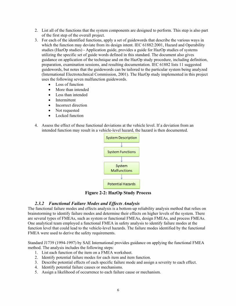
2.3.1 Hazard and Operability Study This research uses the HazOp study as one of the methods for identifying vehicle-level hazards. Figure 2-2 illustrates the analytical steps of the HazOp study:
1. Define the system of study and the scope of the analysis. Draw a block diagram to illustrate the system components, system boundary, and interfaces. This step is part of the first step of the overall project (described in Section 2.2).
6
2. List all of the functions that the system components are designed to perform. This step is also part of the first step of the overall project.
3. For each of the identified functions, apply a set of guidewords that describe the various ways in which the function may deviate from its design intent. IEC 61882:2001, Hazard and Operability studies (HazOp studies) - Application guide, provides a guide for HazOp studies of systems utilizing the specific set of guide words defined in this standard. The document also gives guidance on application of the technique and on the HazOp study procedure, including definition, preparation, examination sessions, and resulting documentation. IEC 61882 lists 11 suggested guidewords, but notes that the guidewords can be tailored to the particular system being analyzed (International Electrotechnical Commission, 2001). The HazOp study implemented in this project uses the following seven malfunction guidewords.
• Loss of function • More than intended • Less than intended • Intermittent • Incorrect direction • Not requested • Locked function
4. Assess the effect of these functional deviations at the vehicle level. If a deviation from an
intended function may result in a vehicle-level hazard, the hazard is then documented.
Figure 2-2: HazOp Study Process
2.3.2 Functional Failure Modes and Effects Analysis
The functional failure modes and effects analysis is a bottom-up reliability analysis method that relies on brainstorming to identify failure modes and determine their effects on higher levels of the system. There are several types of FMEAs, such as system or functional FMEAs, design FMEAs, and process FMEAs. One analytical team employed a functional FMEA in safety analysis to identify failure modes at the function level that could lead to the vehicle-level hazards. The failure modes identified by the functional FMEA were used to derive the safety requirements. Standard J1739 (1994-1997) by SAE International provides guidance on applying the functional FMEA method. The analysis includes the following steps:
1. List each function of the item on a FMEA worksheet. 2. Identify potential failure modes for each item and item function. 3. Describe potential effects of each specific failure mode and assign a severity to each effect. 4. Identify potential failure causes or mechanisms. 5. Assign a likelihood of occurrence to each failure cause or mechanism.

7
6. Identify current design controls that detect or prevent the cause, mechanism, or mode of the failure.
7. Assign a likelihood of failure detection to the design control. This study applies the first four steps listed above for the functional FMEA. Since this study is implemented at the concept phase and is not based on a specific design, the FMEA does not assume controls or mitigation measures are present; there is no data to support Steps 5 through 7. The completed functional FMEA worksheet is intended to be a living document that is updated continually throughout the development process.
2.3.3 Fault Tree Analysis The fault tree analysis approach is a top-down method described by the International Electrotechnical Commission in its standard IEC 61025 (2006-12). It assumes a top-level failure or loss of functionality (in this case, a vehicle-level hazard) and evaluates the causal chain of events that can produce that failure. At each level of the tree, there may be multiple potential causes that contribute to the failure. The next higher level of failure may result from a range of combinations of failures connected through Boolean gates (e.g., AND, OR). For example, Event X might happen only if precursor Event A occurs AND (Event B occurs OR Event C occurs). This approach is particularly useful for probabilistic studies if the probabilities of the underlying events can be determined, as the mathematical techniques for the Boolean analysis are well understood. A separate fault tree must be constructed for each vehicle-level hazard.
2.3.4 System Theoretic Process Analysis The application of the STPA method to automotive electronic control systems is relatively new. Unlike HazOp, FTA, and Functional FMEA, a standard approach has not yet been defined and published for STPA. Therefore, this report provides more descriptions in order to better explain how the analysis was performed. The STPA is a top-down systems engineering approach to system safety (Leveson, 2012). In STPA, the system is modelled as a dynamic control problem, where proper controls and communications in the system ensure the desired outcome for emergent properties such as safety. In the STPA framework, a system will not enter a hazardous state unless an unsafe control action is issued by a controller or a control action needed to maintain safety is not issued. Figure 2-3 shows a process flow diagram for the STPA method.
Figure 2-3: STPA Process
STPA uses a representation of a hierarchical control structure to describe the system and the scope of the analysis. Figure 2-4 shows a generic hierarchical control structure in the format of a feedback control
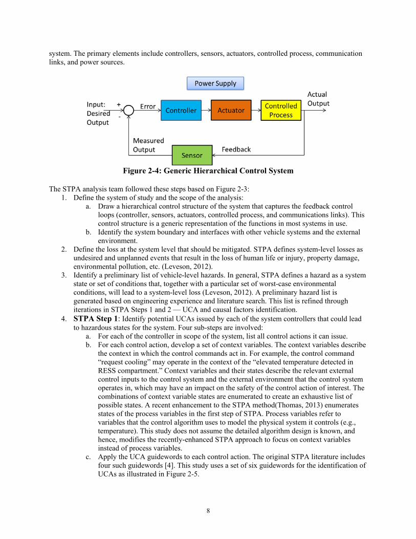
8
system. The primary elements include controllers, sensors, actuators, controlled process, communication links, and power sources.
Figure 2-4: Generic Hierarchical Control System
The STPA analysis team followed these steps based on Figure 2-3:
1. Define the system of study and the scope of the analysis: a. Draw a hierarchical control structure of the system that captures the feedback control
loops (controller, sensors, actuators, controlled process, and communications links). This control structure is a generic representation of the functions in most systems in use.
b. Identify the system boundary and interfaces with other vehicle systems and the external environment.
2. Define the loss at the system level that should be mitigated. STPA defines system-level losses as undesired and unplanned events that result in the loss of human life or injury, property damage, environmental pollution, etc. (Leveson, 2012).
3. Identify a preliminary list of vehicle-level hazards. In general, STPA defines a hazard as a system state or set of conditions that, together with a particular set of worst-case environmental conditions, will lead to a system-level loss (Leveson, 2012). A preliminary hazard list is generated based on engineering experience and literature search. This list is refined through iterations in STPA Steps 1 and 2 — UCA and causal factors identification.
4. STPA Step 1: Identify potential UCAs issued by each of the system controllers that could lead to hazardous states for the system. Four sub-steps are involved:
a. For each of the controller in scope of the system, list all control actions it can issue. b. For each control action, develop a set of context variables. The context variables describe
the context in which the control commands act in. For example, the control command “request cooling” may operate in the context of the “elevated temperature detected in RESS compartment.” Context variables and their states describe the relevant external control inputs to the control system and the external environment that the control system operates in, which may have an impact on the safety of the control action of interest. The combinations of context variable states are enumerated to create an exhaustive list of possible states. A recent enhancement to the STPA method(Thomas, 2013) enumerates states of the process variables in the first step of STPA. Process variables refer to variables that the control algorithm uses to model the physical system it controls (e.g., temperature). This study does not assume the detailed algorithm design is known, and hence, modifies the recently-enhanced STPA approach to focus on context variables instead of process variables.
c. Apply the UCA guidewords to each control action. The original STPA literature includes four such guidewords [4]. This study uses a set of six guidewords for the identification of UCAs as illustrated in Figure 2-5.

9
Figure 2-5: Guidewords for Unsafe Control Actions
For each control action, assess each of the six guidewords against each of the context variable combinations to determine if it could lead to vehicle-level hazards. If a new hazard were identified, add it to the vehicle-level hazard list initiated in the previous step.
d. Apply logical reduction to the resulting UCA matrix using the Quine-McCluskey minimization algorithm (Coudert, 1994) in order to reduce the number of UCA statements.
STPA Step 1 produces a list of UCAs that can be used to derive Functional Safety Requirements for software control logic and initiate the STPA Step 2 analysis.
5. STPA Step 2: Determine CFs for each UCA identified in STPA Step 1. Each component and connection in the control structure representation of the system is analyzed to determine if the component or the connection may contribute to one of the UCAs identified in STPA Step 1. STPA literature provides 17 guidewords to assist the analyst in identifying CFs (Leveson, 2012). This project used an expanded list of 26 guidewords for identifying CFs.
Please note as discussed above, there are two main analysis steps in STPA (Figure 2-3). This project applies STPA Step 1 in the hazard analysis stage of the study and STPA Step 2 as part of the safety analysis stage illustrated in Figure 2-1.
2.4 Automotive Safety Integrity Level In the final step of the HARA, an ASIL classification is assigned to each potential hazard. The five ASIL categories are QM (that is, a scenario that can be addressed through quality management methods), A, B, C, and D, with D being the most severe. The ASIL rating is a function of three parameters: Exposure, Severity, and Controllability. ISO 26262 defines the parameters as follows:
1. Exposure: “State of being in an operational situation that can be hazardous if coincident with the failure mode under analysis.” Assigned based on the percentage of the overall operating time of the vehicle during which the hazard can occur or as a frequency of the exposure to the operating scenario.
2. Severity: “Estimate of the extent of harm to one or more individuals that can occur in a potentially hazardous situation.”
3. Controllability: “Ability to avoid a specific harm or damage through the timely reactions of the persons involved, possibly with support from external measures.”

10
ISO 26262 (2011) defines standards for rating the exposure, severity, and controllability of vehicle level hazards on the basis of the details of malfunction scenarios that can create the hazard. The ASIL classification of a hazard is taken as the most severe of the ratings for all the scenarios that can generate that hazard. For example, if two distinct malfunction scenarios can generate a particular hazard and one produces an ASIL B classification while the other produces an ASIL C classification, the hazard is to be treated as an ASIL C. Exposure is rated using the five-level scale from ISO 26262, as shown in Table 2-1.
Table 2-1: ISO 26262 Exposure Ratings Class E0 E1 E2 E3 E4
Description Incredible Very low probability (not specified)
Low probability (less than 1% of average operating time)
Medium probability (1% to 10% of average operating time)
High probability (More than 10% of average operating time)
ISO 26262 defines Severity and Controllability on four-level scales as shown in Table 2-2 and Table 2-3.
Table 2-2: ISO 26262 Severity Ratings Class S0 S1 S2 S3
Description No injuries Light and moderate injuries
Severe and life-threatening injuries (survival probable)
Life-threatening injuries (survival uncertain), fatal injuries
Table 2-3: ISO 26262 Controllability Ratings Class C0 C1 C2 C3
Description Controllable in general
Simply controllable; 99% or more of all drivers or other traffic participants are usually able to avoid a specific harm
Normally controllable; 90% or more of all drivers or other traffic participants are usually able to avoid a specific harm
Difficult to control or uncontrollable; Fewer than 90% of all drivers or other traffic participants are usually able to avoid a specific harm
Once a hazard is assigned exposure, severity, and controllability ratings, an ISO 26262 ASIL is assigned based on Table 2-4. Whenever a hazard is rated as E0, S0, or C0, no ASIL classification is assigned to the hazard. Note that only the most severe combination of all three ratings results in an ASIL D classification.
Table 2-4: Assignment of ISO 26262 Automotive Safety Integrity Level Based on Exposure, Severity, and Controllability Ratings
C1 C2 C3
S1 E1 QM QM QM E2 QM QM QM E3 QM QM A E4 QM A B
S2 E1 QM QM QM E2 QM QM A

11
C1 C2 C3
E3 QM A B E4 A B C
S3 E1 QM QM A E2 QM A B E3 A B C E4 B C D
2.5 Functional Safety Concepts The ISO 26262 analyses use the ranked hazards resulting from the HARA to define Safety Goals and related FSCs. As stated above, the Safety Goals are derived from the identified hazards (i.e., that they do not occur). The FSCs are used in conjunction with the safety goals to derive the Functional Safety Requirements and to allocate them to the preliminary architectural elements of the system or to external risk reduction measures in order to achieve that level of safety. These relationships are depicted schematically in Figure 2-6.
Figure 2-6: Relationships and Derivation of Functional Safety Requirements (Soden, 2011)
2.6 Functional Safety Requirements This research used the Hazard and Operability (HazOp) analysis referenced in the International Standards Organization 26262 standard as well as the System Theoretic Process Analysis. One Volpe team and one consultant team separately performed the HazOp analysis and subsequent Hazard Analysis and Risk Assessment that resulted in the assignment of Automotive Safety Integrity Levels to the identified hazards and the formulation of Functional Safety Concepts for automotive RESSs. ASIL ratings involve some degree of analytical judgment especially as applied to generic systems. Another Volpe team applied the STPA method and consulted with subject matter experts with specific technical systems expertise. Beyond an assessment of the hazards related to the RESS, these analyses provided input to diagnostics communication and messaging requirements for electronic systems in general. ISO 26262 recommends that the “Functional Safety Strategy” include three crucial parts.
• Fault detection and failure mitigation • Safe states, including system operation degradation strategy • Operator warning strategy
12
The goal in generating “Functional Safety Requirements” is to establish methods that can ensure that the parameters monitored by the system components are validated1 and correct,2 and that the actions taken by the system components are correct and confirmed. These requirements also include methods, in case of a hazardous event, to ensure that the system transitions into the correct safe state within the correct time and that the driver is properly informed. A robust system could be designed such that more than two fully independent failures would be required to defeat the safety strategy and create the possibility of a safety-critical event. That is, any single fault or dual-point fault of an element should not lead to a safety-critical event. When any single or dual-point system fault is detected, the safety strategy is to bring the system to a safe state that can ensure the safety of the vehicle occupants and others. A safe state can be a degraded performance state of the system. When a fault requiring transition to a safe state is detected, appropriate diagnostic trouble codes are set and appropriate data are logged such as the actual time required to reach the defined safe state. Warnings to the operator may contribute significantly to overall vehicle safety. Such warnings are designed to balance the need to avoid distracting and overwhelming drivers with the requirement to inform operators of hazards that require their attention to maintain the safety of the vehicle, its occupants, and others. Section 4.3 provides a list of general “Functional Safety Requirements.”
2.7 Diagnostics and Prognostics This report addresses diagnostics and prognostics that are limited to the sensing and evaluation of elements of the RESS itself. That is, while external interfaces may be amenable to diagnostic or prognostic evaluation, this report focuses on methodologies for identifying existing and potential problems with the battery pack, the battery management system, and any power distribution components. For example, there is no quantitative assessment of methodologies to predict consequences for RESS health if there were a detected failure of a cooling system. Many diagnostic functions are characterized by detecting when a key parameter strays out of its normal operating range. In any electronic system, short-term anomalies are possible in both the sensor and the communications network. The hazard analysis identified Fault Tolerant Times over which a fault had to be identified and mitigated. The FTTs for many serious malfunctions are significantly less than one second. ISO 26262 recommends that diagnostics covering the safety-related functionality should be instituted with a level of coverage corresponding to the ASIL of the safety goal that is affected. Diagnostics are important for significant failure modes of the RESS, such as those in Section 4.4. There are recommendations for safety-related diagnostics corresponding to the ASIL of the safety goal that is affected. Prognostics research supports predicting when RESSs are at risk of becoming unacceptably vulnerable to hazardous scenarios.
1 “Validated” in this context means that the value of a parameter or the state of an element falls within a valid range of values or states. 2 “Correct” means that the value of a parameter is accurate within the valid range.
13
2.8 Validation Testing Standards such as ISO 26262 recommend safety validation testing to confirm that the RESS safety goals are achieved. A validation approach could include appropriate tests using one or more of the following methods.
• Analysis • Simulation • User tests under real-world conditions • Fault injection tests • Stress tests • Highly accelerated life tests
Each test procedure ideally would contain quantitative measures of the following metrics, where appropriate.
• Vehicle controllability • Appropriate fault mitigation • Fault tolerant time • Issuance of appropriate operator warning • Achievement of appropriate low operating strategy • Setting of appropriate diagnostic trouble code • Accurate and appropriate data logging
Vehicle-specific quantitative pass/fail criteria might be developed.

14
3. Results: Hazard Analysis and Risk Assessment The backbone of this research is the determination and analysis of the potential vehicle-level hazards that can occur in a RESS-equipped vehicle and associated determination of the relative risk levels that these hazards might pose to vehicles in the fleet. This chapter describes the application of the functional safety methodologies used to establish and assess these hazards. General results are presented and detailed analyses are provided in the appendices.
3.1 Results for Hazard Analyses The technical approach for this effort included a comprehensive, multifaceted hazard analysis. Two teams, one from Volpe and one with expert consultants, employed the HazOp approach. An additional Volpe team with RESS industry experience as well as expertise in the STPA process used that technique to produce an additional hazard analysis.
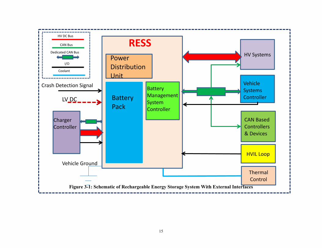
3.1.1 System Block Diagrams In all three hazard analyses, the team developed a block diagram of a generic RESS to characterize the system, its functions, the control hierarchy, and the interactions of its components. The teams included a graphical depiction of the external interfaces with which the RESS connects. These figures are useful for defining the scope of the analysis, particularly in identifying those components outside of RESS, which may contain malfunctions or UCAs that the RESS control system would face. Figure 3-1 is a representative high-level diagram of a generic RESS and its interfaces with other vehicle systems. Analysts generated more detailed diagrams in their analyses. At a basic level, a RESS includes energy storage components (e.g., battery packs and modules), components for receiving (i.e., charging) and distributing stored electro-chemical energy, sensors, and an electronic control system (e.g., BMS), along with interfaces that communicate with other vehicles systems, provide environmental control (i.e., heating and cooling), and provide basic safety functions (e.g., high voltage interlock loop).
15
Figure 3-1: Schematic of Rechargeable Energy Storage System With External Interfaces
Battery
Pack
Power
Distribution
Unit
Battery
Management System
Controller
Vehicle Systems Controller
HV Systems
CAN Based
Controllers & Devices
HVIL Loop
Charger Controller
RESS
Vehicle Ground
HV DC Bus
CAN Bus
I/O
Coolant
LV DC
Crash Detection Signal
Dedicated CAN Bus
Thermal Control

16
3.1.2 Functions and Malfunctions (HazOp) The HazOp teams investigated functions of the system and its components and the hazards that might be associated with possible malfunctions such as functions:
• Not happening at all • Happening when it should not • Happening to the wrong degree (too much, too little, wrong direction) • Happening with the wrong timing (too early, too late, or intermittent)
An example for one function is shown in Table 3-1. Functions and malfunctions for the two HazOp analyses are described in Appendices B and C.
Table 3-1: Examples of Hazard and Operability Analysis
RESS Function Malfunction Potential Vehicle Hazard
Accepts and stores high-voltage electrical energy from both on-board and off-board chargers
Does not accept energy None Excessive acceptance of energy Thermal Event and/or Cell Venting
and Chemical Release Reduced acceptance of energy None Accepts energy when not supposed to
Thermal Event and/or Cell Venting and Chemical Release
Continues to accept energy after reaching full State of Charge (SOC)
Thermal Event and/or Cell Venting and Chemical Release
3.1.3 Control Actions and Unsafe Control Actions (STPA) STPA is based on control system theory and is therefore concerned with the control, feedback, and actuation aspects of system elements. The Volpe STPA team determined that the BMS has 10 control actions that directly affect the safety of the RESS. The 10 control actions and the associated 66 UCAs for the BMS are given in Appendix D. Other controllers (e.g., driver, Vehicle Systems Controller) can also affect the RESS, but this analysis also examines whether the BMS can mitigate the RESS-related UCAs of those controllers through its own actions. Table 3-2 gives an example of an STPA UCA and its relation to hazard and loss.
Table 3-2: Example of STPA Unsafe Control Action UCA If the BMS controller sends the charging request to the hybrid vehicle controller too late, it
may lead to battery cells being over-discharged. Hazard Anode copper current collector is dissolved into the electrolyte Loss Thermal Event and/or Cell Venting and Chemical Release
3.2 Results for Losses, Hazards, Failures, and Faults The three hazard analyses yielded similar results for vehicle level hazards. Differences existed in how the analyses characterized the scenarios that could lead to these events due to the assumptions of the team, as well as the nature and nomenclature of the analyses. For reference, definitions of key terms for the two hazard analytical approaches are given in Appendix E.
3.2.1 Vehicle-Level Hazards or Losses The three hazard analyses identified four vehicle-level hazards relevant to the functions and control actions of the BMS.
• Thermal event • Cell venting and chemical release
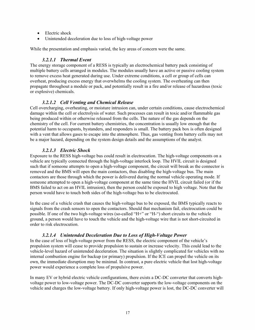
17
• Electric shock • Unintended deceleration due to loss of high-voltage power
While the presentation and emphasis varied, the key areas of concern were the same.
3.2.1.1 Thermal Event The energy storage component of a RESS is typically an electrochemical battery pack consisting of multiple battery cells arranged in modules. The modules usually have an active or passive cooling system to remove excess heat generated during use. Under extreme conditions, a cell or group of cells can overheat, producing excess energy that overwhelms the cooling system. The overheating can then propagate throughout a module or pack, and potentially result in a fire and/or release of hazardous (toxic or explosive) chemicals.
3.2.1.2 Cell Venting and Chemical Release Cell overcharging, overheating, or moisture intrusion can, under certain conditions, cause electrochemical damage within the cell or electrolysis of water. Such processes can result in toxic and/or flammable gas being produced within or otherwise released from the cells. The nature of the gas depends on the chemistry of the cell. For current battery chemistries, the concentration is usually low enough that the potential harm to occupants, bystanders, and responders is small. The battery pack box is often designed with a vent that allows gases to escape into the atmosphere. Thus, gas venting from battery cells may not be a major hazard, depending on the system design details and the assumptions of the analyst.
3.2.1.3 Electric Shock Exposure to the RESS high-voltage bus could result in electrocution. The high-voltage components on a vehicle are typically connected through the high-voltage interlock loop. The HVIL circuit is designed such that if someone attempts to open a high-voltage component, the circuit will break as the connector is removed and the BMS will open the main contactors, thus disabling the high-voltage bus. The main contactors are those through which the power is delivered during the normal vehicle operating mode. If someone attempted to open a high-voltage component at the same time the HVIL circuit failed (or if the BMS failed to act on an HVIL intrusion), then the person could be exposed to high voltage. Note that the person would have to touch both sides of the high-voltage bus to be electrocuted. In the case of a vehicle crash that causes the high-voltage bus to be exposed, the BMS typically reacts to signals from the crash sensors to open the contactors. Should that mechanism fail, electrocution could be possible. If one of the two high-voltage wires (so-called “H+” or “H-“) short circuits to the vehicle ground, a person would have to touch the vehicle and the high-voltage wire that is not short-circuited in order to risk electrocution.
3.2.1.4 Unintended Deceleration Due to Loss of High-Voltage Power In the case of loss of high-voltage power from the RESS, the electric component of the vehicle’s propulsion system will cease to provide propulsion to sustain or increase velocity. This could lead to the vehicle-level hazard of unintended deceleration. The situation is slightly complicated for vehicles with no internal combustion engine for backup (or primary) propulsion. If the ICE can propel the vehicle on its own, the immediate disruption may be minimal. In contrast, a pure electric vehicle that lost high-voltage power would experience a complete loss of propulsive power. In many EV or hybrid electric vehicle configurations, there exists a DC-DC converter that converts high-voltage power to low-voltage power. The DC-DC converter supports the low-voltage components on the vehicle and charges the low-voltage battery. If only high-voltage power is lost, the DC-DC converter will

18
cease to function, but the low-voltage battery should continue to support the safety functions of the vehicle, including allowing the BMS to open the main contactors. The RESS is typically designed to require power to “close” the main contactors (that is, enable the high-voltage bus from the battery pack). In case of a catastrophic failure where all power on the vehicle is lost, the main contactors are designed to open, yielding a safe state under failure conditions (“fail safe”). Some critical vehicle safety modules (e.g., the crash detection module) have an internal power supply that can keep them functioning long enough to activate the appropriate safety mechanisms of the vehicle. Nonetheless, a loss of multiple electronic vehicle systems in conjunction with reduced propulsion will affect the controllability of the hazard.
3.2.2 Intermediate and Component-Level Faults and Failures The interactions of the electronic, electrochemical, and mechanical components of the RESS can lead to complex fault and failure scenarios. The severity and effects of the faults are influenced by the details of the design. For example, as designs feature electrochemical cells which are larger and/or more tightly arranged in a pack, it may be more likely that a local failure (e.g., over-temperature) can adversely affect nearby cells and more quickly result in cascading failure scenarios. The following sections of this report examine intermediate level faults, which are defined as issues that can occur at levels between the vehicle level and the component level and can lead to vehicle-level hazards. The intermediate level faults identified in this analysis can be categorized into four broad groups.
• Charge management • Thermal management • Chemical generation and enclosure integrity • Power management
A consolidated list of relevant intermediate-level component faults and failures, and/or UCAs is provided below.
3.2.2.1 Charge Management Typical RESS cells have a defined range of acceptable charge (often measured in terms of available cell voltage). For Li-ion batteries, these ranges can be quite narrow. There are electrochemical implications for excursions outside the acceptable range. Small variations from optimum can affect the effectiveness of the RESS by affecting its ability to store and release energy. More severe variations can have direct safety implications. Overcharging Li-ion cells can result in deposition of metallic lithium within the cell, resulting in the formation of metallic dendrites that can puncture the cell’s separator. This can, in turn, lead to localized resistive heating. The formation of metallic dendrites may be exacerbated by charging when the cell is at a temperature below the normal charging temperature range. Over-discharge of a Li-ion cell could lead to damage of the copper anode current collector and possibly puncture the cell’s separator as well. To manage the charge globally, the RESS charge level is typically monitored by the BMS, which can call for charging if the global charge level is in danger of falling too low and/or disallow charging if the global charge level is in danger of going too high. The charge of the individual cells is typically managed by cell balancing. If there were no compensation mechanism for variations in cell manufacturing, minor differences in internal resistance would be exacerbated by repeated charging, resulting in rapid degradation of some cells. Cell balancing can be active or passive. Active control is more complex to design and manufacture, but likely more efficient in terms of reduced energy dissipation. In comparison, passive balancing is cheaper and simpler, but it does rely on dissipation of voltage differences through resistive heating.

19
For these reasons, any malfunctions or UCAs that lead to improper overcharging or over-discharging can be expected to have negative effects on the health of the RESS and the safety of the vehicle occupants. These malfunctions and UCAs are included in Table 3-3 and include all insufficient implementations of component behaviors and control actions intended to sense, control, and actuate maintenance of appropriate charge levels. That is, Table 3-3 provides a consolidated list of intermediate-level faults, failures, and unsafe control actions from the three analyses that might lead to the vehicle-level hazards in Section 3.2.1. The entries ascribe whether they might affect RESS charge level, RESS temperature level, the RESS’s ability to enclose and contain hazardous chemicals, and the RESS’s ability to control high-voltage power.
Table 3-3: Intermediate-Level Faults, Failures, and Unsafe Control Actions Fault, Failure, or Unsafe Control Action Charge Thermal Enclosure Power
BMS commands/allows overcharge X X X X BMS commands/allows over-discharge X X X X BMS allows/commands charging while RESS too cold X X X X Improper active or passive cell balancing X X X X Internal cell short circuits X X X Internal pack short circuits X X X External short circuit or ground fault X X X X Faulty or corrupt communication – command X X X X Faulty or corrupt communication – sensor X X X X Faulty temperature sensor X X X Faulty voltage sensor X X X X Faulty current sensor X X X X BMS allows/commands too much cooling or heating X X X BMS allows/commands too little cooling or heating X X X Faulty cooling system X X X BMS allows/commands improperly open contactors X BMS allows/commands improperly closed contactors X X X X System state requiring open contactors X BMS allows/commands improperly open pre-charge contactor
X X X X
BMS allows/commands improperly closed pre-charge contactor
X X X X
Undetected or otherwise unmitigated moisture intrusion X Mechanical failure of the RESS enclosure – crash X X Mechanical failure of the RESS enclosure – age, abuse, or defect
X X
BMS allows/commands too much current X X X X BMS allows/commands too little current X X X X PDU allows/commands too much current X X X X PDU allows/commands too little current X X X X Faulty cell or pack X X X Faulty HVIL X Faulty ground detection X

20
3.2.2.2 Thermal Management Typical RESS cells also have a defined range of acceptable temperature. Li-ion cells tend to function best in the temperature range in which humans are comfortable. Once again, the adverse effects of being out of the nominal temperature range have more immediate consequences for the durability of the cell than the safety of the vehicle. However, over time, instabilities can arise that might lead to thermal events. High temperatures within a Li-ion cell can result in breakdown of the cathode as it reacts with the electrolyte, resulting in generation of oxygen, breakdown of the passivation layer (solid electrolyte interface or SEI) in which the anode reacts with the electrolyte in a self-heating reaction, or other chemical reactions involving the breakdown of electrolyte and release of heat. A general thermal model is considered for thermal management of the RESS. The specific threshold temperatures would be dependent on the details of the RESS design. As the temperatures of individual cells in the RESS increase, they can eventually reach a point, Tonset, where self-heating can commence. That is, once a cell temperature exceeds Tonset, even if the electric load were removed from the cell, its temperature may continue to increase unless cooling were applied. An active cooling system (and some passive cooling systems, depending on design) may be able to prevent further temperature increase. A transitional temperature, Ta, can be defined for a particular RESS design at which the self-heating phenomenon is in danger of exceeding the cooling capability of the cooling system. At this temperature, an eventual thermal event becomes probable. The “thermal runaway” temperature, Tr, is that temperature at which a thermal event has commenced and further damage is uncontrollable and unavoidable. The design of Li-ion cells typically includes a permeable separator which can melt into an impermeable layer upon reaching a critical temperature. This process will render a cell useless but may limit the heat released in an otherwise unstable thermal event. Design details will dictate whether a scenario in which a separator melts will result in significant loss of propulsive power. For these reasons, any malfunctions or UCAs, including the failure to compensate for extreme environmental conditions, which lead to improper temperatures, can be expected to have adverse effects on the health of the RESS and the safety of vehicle occupants. These malfunctions and UCAs are listed in Table 3-3 and include all insufficient implementations of component behaviors and control actions intended to sense, control, and actuate maintenance of appropriate temperature levels, as well as those effects from improper charge levels.
3.2.2.3 Chemical Generation and Enclosure Integrity A RESS is designed to be chemically stable and not release explosive, toxic, or otherwise hazardous chemicals. Part of that design typically includes an enclosure for the electrochemical components (in part) to address any thermal or electrochemical malfunction or UCA that results in the generation of toxic or otherwise hazardous chemicals. In particular, any mechanisms resulting in significant accumulation of moisture within the enclosure that could come in contact with the high-voltage bus could be hazardous. Any overheating or overcharging scenarios can contribute to these hazards. Finally, any mechanical failure or RESS penetration that might result from a dynamic event such as a crash or from long-term use and wear could enable such hazards. These faults, failures, and UCAs are included in Table 3-3.
3.2.2.4 Power Management The RESS is intended to provide high-voltage power to enable propulsion while safeguarding occupants and others. Even in a carefully considered mitigation sequence in which high-voltage propulsive power is disrupted for immediate safety reasons (such as to inhibit thermal runaway or electric shock), there is some danger if the disruption significantly and adversely affects the propulsive function of the RESS or

21
other key vehicle functions. Electric vehicles with no internal combustion engine have no alternative source of propulsion in situations where the RESS can no longer deliver power. If the vehicle design uses the RESS to provide non-propulsive primary vehicle functions (e.g. lighting, power steering), any loss of RESS could create other hazards as well. For these reasons, any malfunctions or UCAs which can lead to the loss of RESS power may imperil overall vehicle safety. These malfunctions and UCAs are listed in Table 3-3.
3.2.3 Causal Factors and Faults Causal factors are problems with the electronic control system components (controller, sensor, actuator, communication links, and power supply), interactions among these components, their interactions with the rest of the vehicle, and their interactions with the external environment that may cause the controller to issue a potential UCA and lead to a vehicle hazard. The causal factors from the STPA analysis are enumerated in Appendix F. ISO 26262 defines faults as abnormal conditions that can cause an element or an item to fail. For example, intermittent sensor or communication issues might cause the BMS to miscalculate the state of charge (SOC), state of health, or degree of cell imbalance within the RESS. Under those conditions, the BMS might issue control actions that could lead to a higher level failure. A list of possible faults was generated in the first implementation of HazOp and is given in Appendix G. The causal factors for the faults, failures, and UCAs in Table 3-3 can be divided into three general categories. The first is a hardware failure—a device (e.g., sensor, communication path, actuator) which physically does not operate or perform as intended and, under normal circumstances, can. This non-performance could be an issue of manufacturing, maintenance (including normal but unmitigated component degradation), electromagnetic interference (see Appendix H), abuse (e.g., physical interference, environmental exposure), or defect. It might also result from an improperly initialized or calibrated system component. The failure of the low-voltage power supply may effectively result in the failure of some sensors and systems. The second possibility is a potential software or algorithm design or implementation issue. In this category, the sensors provide the appropriate timely data, the actuator and physical system behave in a predictable manner, but the commanded actuation is not appropriate for the conditions. This could be a simple software bug or it could be an incorrect or insufficiently robust control algorithm. Finally, the system may not physically behave as modeled in the control system. This might be the effect of environmental conditions (e.g., extreme temperature, electromagnetic interference) or simply a control model based on an insufficient understanding of the physical system. This differs from an insufficient algorithm that incorporates a sufficient physical model.
3.3 Results for Risk Assessment 3.3.1 Hazards and Scope
The four vehicle level hazards enumerated in Section 3.2.1 can each arise from different scenarios. In the following section, researchers used the ASIL risk assessment metric to evaluate those various scenarios. All of the scenarios considered focus on the performance of the systems and components of the generic RESS and its BMS, and can be instigated by failures either within or outside of the RESS (e.g., cooling system failure). In this analysis, the scope was generally limited to the safety considerations of vehicle occupants, but some plausible incidents in which non-occupants (crash responders, service technicians, occupants of a residence in which unattended charging was occurring in an enclosed garage) were

22
considered. The risk scenarios were rated and functional safety concepts developed in accordance with the ASIL ratings.
3.3.2 Relative Risk and ASIL Ratings In ISO 26262, prioritization of vehicle-level hazards is accomplished through the ASIL rating. The process of assigning an ASIL to a hazard is prescriptive to the extent possible, as shown in Table 2-4. Threshold values of the likelihoods of Exposure, Severity, and Controllability are used to determine scores for those attributes. Exposure is often quantified in terms of rate of occurrence during “operational time.” For RESS-equipped vehicles, operational time may be presumed to include both time with the vehicle on and time with the vehicle charging, even if unattended. SAE Standard J2980 recommends that quantitative data should be used whenever possible. However, sufficiently accurate and precise data to justify a rating may be hard to find. In those cases J2980 recommends using conservative estimates. For example, since Exposure data for rare events and new technologies may not be statistically significant, analysts may choose a conservative approach and simply presume that the event will occur. Similarly, Severity and Controllability are difficult to quantify precisely and consistently. Thus, the assignment of ASIL levels is necessarily a function of the analyst’s judgment. ASIL ratings are assigned to hazards early in the design process, and are meant to guide designs. Therefore, they are not design dependent by definition. Nonetheless, Exposure, Severity, and Controllability can be affected if the designer chooses to employ state-of-the-art design concepts in the system definition. For example, including an HVIL will affect exposure to electric shock in most cases, but may not for extreme crash scenarios. Similarly, a system concept in which the RESS is defined as not within the occupant compartment can affect the presumed exposure to chemical release. For this reason, it is important to assess whether final designs conform to the assumed system definition. While analysts may not agree on final ratings, erring on the conservative side and investigating all scenarios help improve the validity of the final analysis. To illustrate the types of scenarios that need to be evaluated, Table 3-4 details one analytical example for each of the four identified vehicle hazards that could result from particular malfunctions.
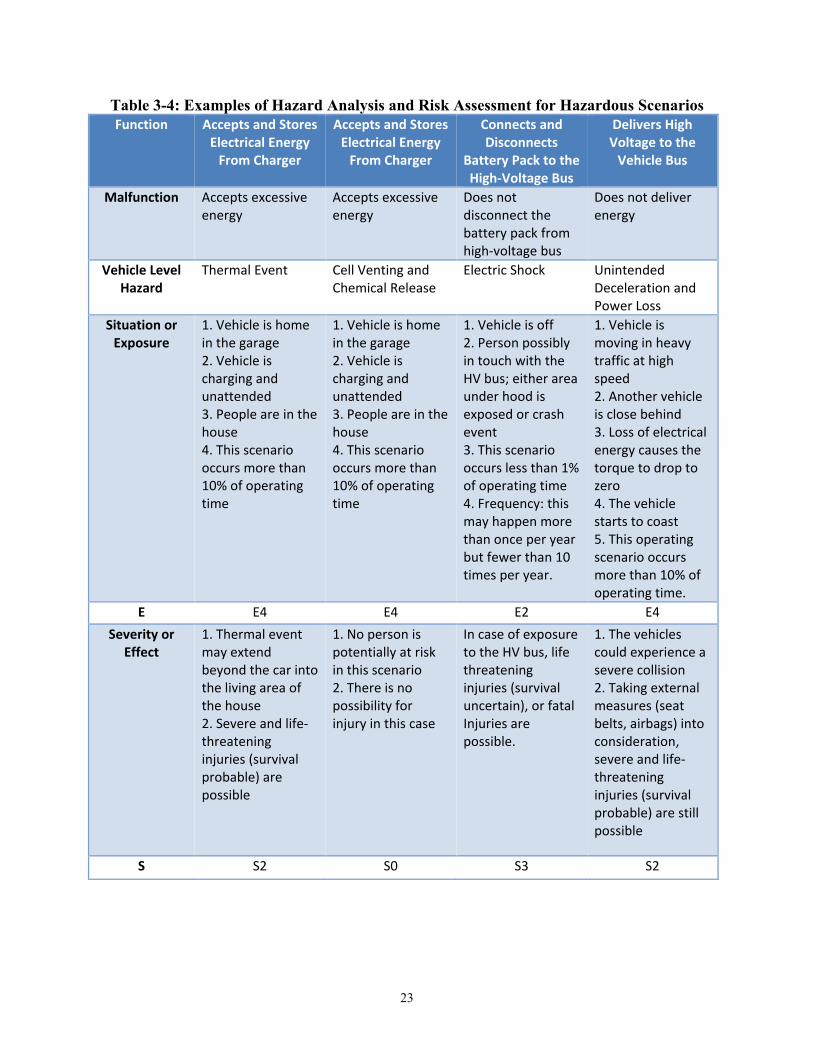
23
Table 3-4: Examples of Hazard Analysis and Risk Assessment for Hazardous Scenarios Function Accepts and Stores
Electrical Energy From Charger
Accepts and Stores Electrical Energy
From Charger
Connects and Disconnects
Battery Pack to the High-Voltage Bus
Delivers High Voltage to the
Vehicle Bus
Malfunction Accepts excessive energy
Accepts excessive energy
Does not disconnect the battery pack from high-voltage bus
Does not deliver energy
Vehicle Level Hazard
Thermal Event Cell Venting and Chemical Release
Electric Shock Unintended Deceleration and Power Loss
Situation or Exposure
1. Vehicle is home in the garage 2. Vehicle is charging and unattended 3. People are in the house 4. This scenario occurs more than 10% of operating time
1. Vehicle is home in the garage 2. Vehicle is charging and unattended 3. People are in the house 4. This scenario occurs more than 10% of operating time
1. Vehicle is off 2. Person possibly in touch with the HV bus; either area under hood is exposed or crash event 3. This scenario occurs less than 1% of operating time 4. Frequency: this may happen more than once per year but fewer than 10 times per year.
1. Vehicle is moving in heavy traffic at high speed 2. Another vehicle is close behind 3. Loss of electrical energy causes the torque to drop to zero 4. The vehicle starts to coast 5. This operating scenario occurs more than 10% of operating time.
E E4 E4 E2 E4 Severity or
Effect 1. Thermal event may extend beyond the car into the living area of the house 2. Severe and life-threatening injuries (survival probable) are possible
1. No person is potentially at risk in this scenario 2. There is no possibility for injury in this case
In case of exposure to the HV bus, life threatening injuries (survival uncertain), or fatal Injuries are possible.
1. The vehicles could experience a severe collision 2. Taking external measures (seat belts, airbags) into consideration, severe and life-threatening injuries (survival probable) are still possible
S S2 S0 S3 S2
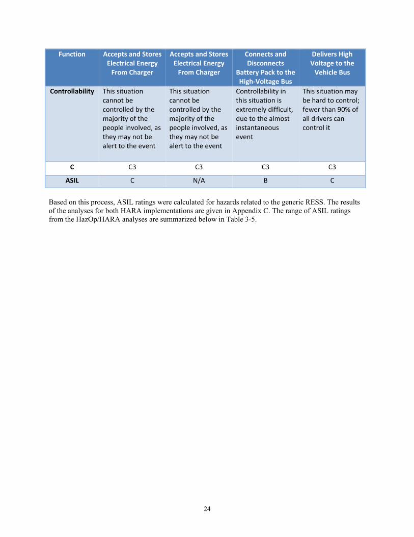
24
Function Accepts and Stores Electrical Energy
From Charger
Accepts and Stores Electrical Energy
From Charger
Connects and Disconnects
Battery Pack to the High-Voltage Bus
Delivers High Voltage to the
Vehicle Bus
Controllability This situation cannot be controlled by the majority of the people involved, as they may not be alert to the event
This situation cannot be controlled by the majority of the people involved, as they may not be alert to the event
Controllability in this situation is extremely difficult, due to the almost instantaneous event
This situation may be hard to control; fewer than 90% of all drivers can control it
C C3 C3 C3 C3
ASIL C N/A B C
Based on this process, ASIL ratings were calculated for hazards related to the generic RESS. The results of the analyses for both HARA implementations are given in Appendix C. The range of ASIL ratings from the HazOp/HARA analyses are summarized below in Table 3-5.
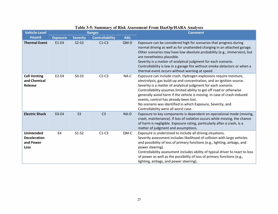
25
Table 3-5: Summary of Risk Assessment From HazOp/HARA Analyses Vehicle-Level
Hazard Ranges Comment
Exposure Severity Controllability ASIL Thermal Event E1-E4 S2-S3 C1-C3 QM-D Exposure can be considered high for scenarios that progress during
normal driving as well as for unattended charging in an attached garage. Other scenarios may have low absolute probability (e.g., immersion), but are nonetheless plausible. Severity is a matter of analytical judgment for each scenario. Controllability is low in a garage fire without smoke detectors or when a thermal event occurs without warning at speed
Cell Venting and Chemical Release
E2-E4 S0-S3 C2-C3 NA-C Exposure can include crash. Hydrogen explosions require moisture, electrolysis, gas build-up and concentration, and an ignition source. Severity is a matter of analytical judgment for each scenario. Controllability assumes limited ability to get off road or otherwise generally avoid harm if the vehicle is moving. In case of crash-induced events, control has already been lost. No scenario was identified in which Exposure, Severity, and Controllability were all worst case.
Electric Shock E0-E4 S3 C3 NA-D Exposure to key components is dependent on operational mode (moving, crash, maintenance). If loss of isolation occurs while moving, the chance of harm is negligible. Exposure rating, particularly after a crash, is a matter of judgment and assumptions.
Unintended Deceleration and Power Loss
E4 S1-S2 C1-C3 QM-C Exposure is understood to include all driving situations. Severity assessment includes likelihood of collision with large vehicles and possibility of loss of primary functions (e.g., lighting, airbags, and power steering). Controllability assessment includes ability of typical driver to react to loss of power as well as the possibility of loss of primary functions (e.g., lighting, airbags, and power steering).
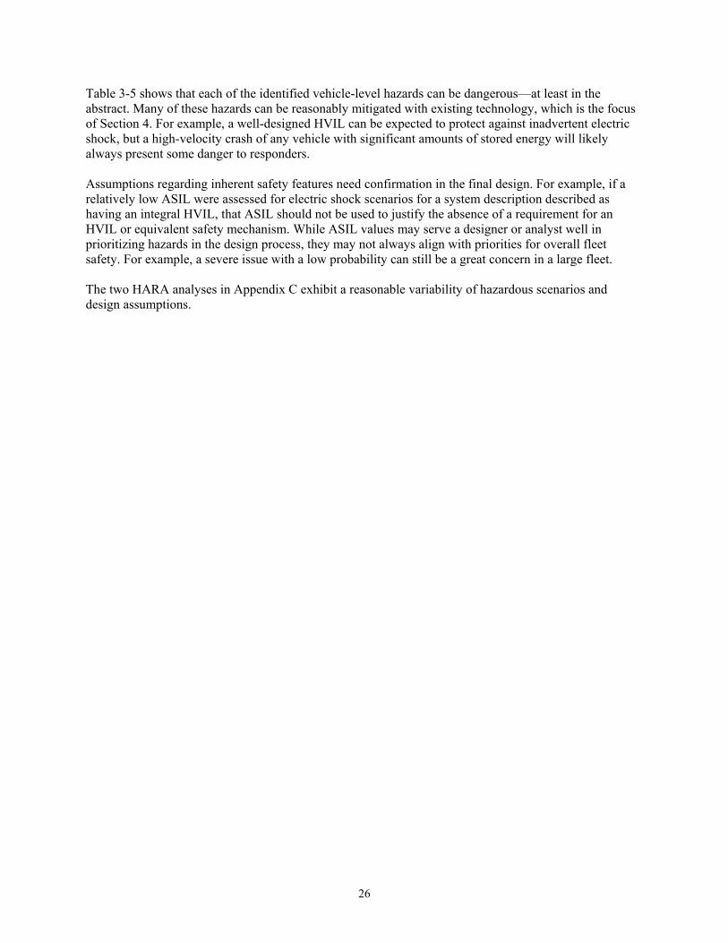
26
Table 3-5 shows that each of the identified vehicle-level hazards can be dangerous—at least in the abstract. Many of these hazards can be reasonably mitigated with existing technology, which is the focus of Section 4. For example, a well-designed HVIL can be expected to protect against inadvertent electric shock, but a high-velocity crash of any vehicle with significant amounts of stored energy will likely always present some danger to responders. Assumptions regarding inherent safety features need confirmation in the final design. For example, if a relatively low ASIL were assessed for electric shock scenarios for a system description described as having an integral HVIL, that ASIL should not be used to justify the absence of a requirement for an HVIL or equivalent safety mechanism. While ASIL values may serve a designer or analyst well in prioritizing hazards in the design process, they may not always align with priorities for overall fleet safety. For example, a severe issue with a low probability can still be a great concern in a large fleet. The two HARA analyses in Appendix C exhibit a reasonable variability of hazardous scenarios and design assumptions.
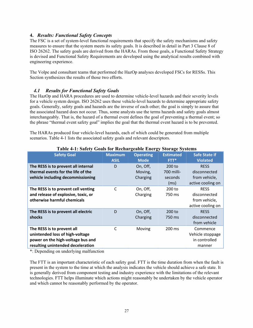
27
4. Results: Functional Safety Concepts The FSC is a set of system-level functional requirements that specify the safety mechanisms and safety measures to ensure that the system meets its safety goals. It is described in detail in Part 3 Clause 8 of ISO 26262. The safety goals are derived from the HARAs. From those goals, a Functional Safety Strategy is devised and Functional Safety Requirements are developed using the analytical results combined with engineering experience. The Volpe and consultant teams that performed the HazOp analyses developed FSCs for RESSs. This Section synthesizes the results of those two efforts.
4.1 Results for Functional Safety Goals The HazOp and HARA procedures are used to determine vehicle-level hazards and their severity levels for a vehicle system design. ISO 26262 uses these vehicle-level hazards to determine appropriate safety goals. Generally, safety goals and hazards are the inverse of each other; the goal is simply to assure that the associated hazard does not occur. Thus, some analysts use the terms hazards and safety goals almost interchangeably. That is, the hazard of a thermal event defines the goal of preventing a thermal event; so the phrase “thermal event safety goal” implies the goal that the thermal event hazard is to be prevented. The HARAs produced four vehicle-level hazards, each of which could be generated from multiple scenarios. Table 4-1 lists the associated safety goals and relevant descriptors.
Table 4-1: Safety Goals for Rechargeable Energy Storage Systems Safety Goal Maximum
ASIL Operating
Mode Estimated
FTT* Safe State if
Violated The RESS is to prevent all internal thermal events for the life of the vehicle including decommissioning
D On, Off, Moving, Charging
200 to 700 milli-seconds
(ms)
RESS disconnected from vehicle,
active cooling on The RESS is to prevent cell venting and release of explosive, toxic, or otherwise harmful chemicals
C On, Off, Charging
200 to 750 ms
RESS disconnected from vehicle,
active cooling on The RESS is to prevent all electric shocks
D On, Off, Charging
200 to 750 ms
RESS disconnected from vehicle
The RESS is to prevent all unintended loss of high-voltage power on the high-voltage bus and resulting unintended deceleration
C Moving 200 ms Commence Vehicle stoppage
in controlled manner
*: Depending on underlying malfunction The FTT is an important characteristic of each safety goal. FTT is the time duration from when the fault is present in the system to the time at which the analysis indicates the vehicle should achieve a safe state. It is generally derived from component testing and industry experience with the limitations of the relevant technologies. FTT helps illuminate which actions might reasonably be undertaken by the vehicle operator and which cannot be reasonably performed by the operator.

28
For a particular hazard in a particular RESS, the relevant faults identified from the safety analysis are ideally monitored via diagnostics. The time from the detection of a fault until the system completes the reaction to it is called the fault reaction time. The idea is that the vehicle has a design that enables it to achieve the safe state within the FTT. The FTT may be limited by the technology and physical processes involved in reaching the safe state. When there are limitations to the direct test data, FTTs are generally estimated from the best available relevant data.
4.2 Results for Functional Safety Strategy ISO 26262 recommends an overarching control strategy to guide the development of “Functional Safety Requirements,” which includes at least the following three aspects.
• Fault detection and failure mitigation • Safe states, including system operation degradation strategy • Operator warning strategy
4.2.1 Fault Detection and Failure Mitigation
Functional Safety Requirements for the RESS should ensure that the parameters monitored by the system components are validated and correct, that the actions taken by the system components are correct and confirmed, that in case of a hazardous event the system transitions into the correct safe state within the correct time, and the driver is properly informed. “Validated” in this context means that the value of a parameter or the state of an element falls within a valid range of values or states. “Correct” means that the value of a parameter is accurate within the valid range. The Volpe team and the consultant team applied the principles in ISO 26262, along with their subject matter expert opinion, to generate the following key elements of a fault detection and failure mitigation strategy for the generic RESS.
• Validate the sensors inputs using an auxiliary processor • Validate the charging current using an auxiliary processor • Validate the status of the main contactors using an auxiliary processor • Validate the status of the pre-charge contactors using an auxiliary processor • Validate the health of the main controller using an auxiliary processor • Ensure that the SOC estimation is accurate • Ensure the validity and correctness of the critical communication inside and outside the RESS • Ensure that low-voltage power is available until the safe state is reached under all failure
conditions • Ensure that active cooling (if design appropriate) is available under all operating modes • Mitigate safety hazards when an unsafe condition is detected. This is done in subsequent design
phases where detailed safety analysis for hardware and software are carried out and the sources of unsafe conditions are defined in terms of the specific failure modes of hardware and software elements.
The two research teams also recommend that the BMS should employ protective strategies that depend upon fail-safe detection of safety-critical faults. Fail-safe monitoring can be implemented through either physical or analytical redundancy. Physical redundancy is based on different electronic components in two or more fully independent functional paths. Redundant computation of the same fault detection algorithms and leveraging physical redundancy inherent in the RESS and BMS system architecture can provide analytical redundancy. It may be possible to provide analytical redundancy without redundant electronics. ISO 26262 recommends that designers should employ appropriate safety mechanisms. A safety mechanism is defined by ISO 26262 as a “technical solution implemented by E/E functions or elements, or by other technologies, to detect faults or control failures in order to achieve or maintain a safe state.”

29
For example, safety mechanisms to prevent RESS thermal events might include: • Thermal design of the RESS that ensures dissipation of the heat from individual cells, especially
during the Vehicle-Off mode • Active cooling enabled during both Vehicle-On and Vehicle-Off modes if design appropriate • Ensuring the health of the main BMS controller (for example, “three-level monitoring” as
described in Appendix J) • A log in the BMS that tracks cell internal impedance changes during the vehicle’s life • Qualification of critical information transfer between cell temperature sensors, cell voltage
sensors, and the battery pack current sensor • Qualification of the critical communication signals between the BMS, the coolant system, and the
charging controller • Qualification of the main contactors status information • High-voltage bus current limiting mechanism • Temperature sensors diagnostics • Cell voltage sensors and diagnostics • Current sensor diagnostics • Ground fault detection circuit diagnostics
Monitoring and evaluation of data from appropriate sensors is necessary to keep hazards in check. In particular, the BMS must be able to assess faults and malfunctions in cell balancing, temperature excursions, and cooling systems. To the extent possible, monitoring signs of system aging as a prognostic methodology for adjusting the acceptable limits of system parameters could improve RESS safety management.
4.2.2 Safe States and System Operation Degradation Strategy According to ISO 26262, no single fault of a system element should lead to a safety-critical event. That is, a system should be designed such that the safety strategy cannot be defeated without two fully isolated and independent RESS failures. When the system detects any single system fault, the BMS should bring the RESS to a “safe state” into which it can transition to ensure the safety of the vehicle occupants and others. When a fault requiring transition to a safe state is detected, the analytical teams recommended that the BMS should also set appropriate DTCs and log appropriate data such as the actual FTT required to reach the defined safe state (rather than the time prescribed in the functional safety concept). For some hazards, one potential safe state might be a degraded performance state of the system. In such a case, a safe state is to be defined in terms of a system operation degradation strategy (Low Operating Strategy (LOS)). LOS possibilities include:
• Disconnection of the RESS from the vehicle (open contactors) • Degraded RESS power delivery (“limp home mode”) • Degraded RESS charging strategy
Appendix I lists examples of safe states for the safety goals investigated by the Volpe HazOp team.
4.2.3 Operator Warning Strategy Warnings to the operator may contribute significantly to overall vehicle safety. ISO 26262 recommends that systems ensure driver warnings are delivered when an unsafe condition is detected. The HazOp teams suggested a preliminary set of operator warnings and system degradation responses in Table 4-2. Each of these conditions minimally requires the setting of a DTC for reference. Note that the details of warnings for certain conditions might vary depending on whether or not the vehicle has an internal combustion engine for backup propulsion (i.e., plug-in HEV (PHEV) and HEV versus pure EV).
30
Table 4-2: Operator Warning Levels and System Mitigation Response
Condition Operator Warning Mitigation Vehicle Effect (PHEV/HEV)
Vehicle Effect (EV)
Normal Operating Limits Reached
None None None None
Normal Operating Limits Exceeded, Potential Violation of Safety Goal
Amber Service Indicator
None if potential for harm is low in current operating mode
None None
Maximum Operating Limits Reached, Potential Violation of Safety Goal, Probability of Hazard Is High
Red Service Indicator plus Message and Audible Chime or Audible Message, Cellular communications if appropriate*, Service Mandatory
Degradation in RESS Energy and Power Provided to Vehicle
RESS Degraded (possibly no detectable change in performance)
Perceptible Vehicle Performance Degradation (“get home mode”)
Maximum Operating Limits Exceeded, Likely Violation of Safety Goal, Probability of Hazard Is High
Red Service Indicator plus Message and Audible Chime or Audible Message, Cellular communications if appropriate*, Service Mandatory
Removal or Major Reduction in RESS Energy and Power Provided to Vehicle
RESS Not Available (“get home mode” relying entirely on internal combustion engine)
Significant Vehicle Performance Degradation (“limp home mode” -minimal RESS performance)
Vehicle Safety Limits Exceeded, Hazard Exists, Safety Goal Violated
Red Service Indicator plus Message (possibly “Exit Vehicle Warning) and Audible Chime or Audible Message, Cellular communications if appropriate*, Service Mandatory
RESS Disconnected from Drive Train
Disabled Vehicle Disabled Vehicle
*: Cellular communication may be appropriate in the case of an unattended vehicle (e.g., unattended charging) or if there is a reasonable possibility of a driver being disabled by the scenario. Note that vehicles employing plug-in or otherwise unattended charging (EV and PHEV) can be considered to be operating while charging, even if unattended. If a safety-critical event (e.g., a thermal event) occurs while unattended, the BMS should be able to respond appropriately, including issuing
31
warnings. External warning options (e.g., sounding horn, sending a cell phone alert, enabling the notification of emergency responders if warranted) might be considered.
4.3 Results for Functional Safety Requirements Functional Safety Requirements are requirements to prevent the vehicle from entering an unsafe state, maintain a safe state, or move the vehicle into a safe state from an unsafe state. The functional safety concept is a set of implementation-independent safety requirements that are derived using guidance from ISO 26262 Part 3 Clause 8 as well as engineering judgment. Functional Safety Requirements can be general in nature or they can be specifically targeted to prevent a particular hazard or group of hazards. This section lists a harmonized set of general requirements derived from the functional safety process followed in this study. Note that many requirements address several threats and are only mentioned once. For example, requirements that prevent RESS overcharging will directly inhibit several modes of thermal runaway and indirectly inhibit various forms of chemical release. The following subsections present the synthesized lists of FSRs developed by the two HazOp teams.
4.3.1 General Fault Detection and Failure Mitigation Requirements Fault detection and failure mitigation requirements capture system-level faults that could lead to violations of the safety goals, and the actions the system could take in order to detect and mitigate the resultant failures. The synthesized list of FSRs includes:
• The BMS is to transition the RESS into a safe state in the event of any failure that violates a safety goal within the FTT interval. This requirement applies to all functions of the BMS.
• The BMS input/output pins must be monitored for short circuits or grounds. • The RESS is to transition into a safe state in case of loss of low-voltage power from the vehicle’s
low-voltage power system. • The RESS is to transition into a safe state when a crash detection signal is received from the
vehicle. • A fail-safe means for the BMS to stop current flow to and from the RESS, typically in the form of
a mechanical or semiconductor contactor, is necessary. The RESS should be able to reach a safe state in the event of power loss in either the high-voltage system or the low-voltage system. The power loss may be incidental (e.g., failure of the low voltage system) or catastrophic (e.g., post-crash). The main contactors should be designed to open (i.e., stop current flow) in the absence of low-voltage power. The time frame for contactors to isolate the RESS should be on the order of milliseconds in order to provide safety in crash events. Designers may consider incorporating an internal backup power supply for the BMS that keeps it alive after the loss of low-voltage power. During this time, the BMS should be able to bring the RESS to the required safe state and log and store critical system data relevant to the event, preferably in a format that can be interpreted by responders.
• The BMS is to control the opening and closing of the main contactors • The main contactors correct status is to be validated in all operating modes. • Main contactors chatter (i.e., fast intermittent opening and closing of contactors) is to be
prevented. • In case of a contactor sticking condition, the RESS is to transition into a safe state within the
established fault tolerant time, currently estimated to be 200 ms. • In case of a contactor welded condition, the RESS is to transition into a safe state within the
established fault tolerant time, currently estimated to be 200 ms.

32
• In case of a contactor unintended opening condition, the RESS is to transition into a safe state within the established fault tolerant time, currently estimated to be 200 ms.
• The BMS is to control the opening and closing of the pre-charge contactors. The pre-charge contactors are used at start up in order to allow the bus voltage to rise while limiting the peak current; this is implemented to reduce the electrical stress on the components of the systems and improve reliability.
• The pre-charge contactors status is to be verified. • The BMS is to be able to detect a contactor stuck open condition. • In case of fault in the main contactors operation (open when they should be closed, closed when
they should be open, or stuck open or closed), the BMS is to transition the system into a safe state within the established fault tolerant time, currently estimated to be 200 ms and send a warning to the driver.
• The health of the BMS main controller is to be ensured. An auxiliary processor is typically used to fulfill this requirement in other vehicle systems. The auxiliary processor independently checks the calculations and decisions made by the main controller. It may also use the “Questions and Answers”-based methodology to ensure the health and sanity of the main controller. In case of failure, the auxiliary processor is to force the system into a safe state within the established fault tolerant time, currently estimated to be 200 ms.
• The operating parameters of a RESS will change under repeated use and as it otherwise ages. An appropriate state of health of the cells of a RESS should be continually assessed as an input to other critical systems.
• The BMS is to estimate battery cell characteristics especially the cell’s internal impedance, and it is to update its estimates throughout the life of the RESS.
• The output of the BMS algorithms that estimates the relevant RESS life characteristics are to be validated. The BMS is to adjust the battery pack SOC estimation algorithm accordingly. The BMS is to adjust the battery pack charging profile accordingly.
• If the BMS detects any potential or actual cell internal short circuit, it is to transition the BMS into a safe state within the established fault tolerant time, currently estimated to be 200 ms, and send a warning to the driver.
• The parameters that govern the SOH (e.g., internal impedance of the cell) are to be established through correlation of electrical and/or thermal measurements to the change in the parameters due to aging. The BMS is to validate the values of these parameters and establish SOH.
• The output of the BMS algorithms for cell internal impedance SOH monitoring is to be validated. This may be based on understanding the thermal profile of a good cell vis-a-vis an internally short-circuited cell.
• The BMS is to employ fail-safe monitoring of impedance between cells (i.e., real-time voltage-based monitoring) to detect localized resistive heating between cells.
• Additional detection may be necessary based on specific cell design and BMS complexity. • In the case of a detected external short-circuit current, the BMS is to transition the RESS into a
safe state within the established fault tolerant time, currently estimated to be 100 ms. • The communication and/or data transfer between the BMS and the power distribution unit must be
qualified for validity and correctness. • The current sensor is to measure the battery pack current at all times, including the vehicle off
mode. • Current sensor values are to be validated for correctness and validity. • The current sensor is to report the battery pack current to the BMS. • The current sensor is to have self-diagnostics to detect failures in its ability to measure and
communicate the measured current values.
33
• In case of an internal failure, the current sensor is to communicate the failure information to the BMS.
• The BMS is to detect and prevent all current overload conditions external to the RESS. • In case of current demand by the system that exceeds the capacity of the RESS, the BMS is to be
provided by a priority strategy by the vehicle system controller. • In case of any overload current conditions and in the absence of a priority strategy from the vehicle
system controller, the BMS is to open the main contactors. • The current limiters are to disconnect the RESS from the vehicle system in case of excessive
current draw. • In case of failure of the current limiters to disconnect the RESS from the vehicle system when
necessary, the RESS is to transition into a safe state within the established fault tolerant time, currently estimated to be 200 ms. The battery back current sensor can be used to ensure correct operation of the current limiters.
• The status of the current limiters is to be reported to the BMS. • The BMS is to communicate the RESS capacity to the vehicle system controller. • The sensor data transmission channels are to be monitored for open or short-circuit conditions. • The BMS is to institute a failure mode effect management strategy to ensure the safety of the
RESS in case of a failure in any critical communications signal. • The strategy is to define the RESS behavior in case of a detected critical signal failure; this
behavior is to include transition to a safe state and FTT. • All communications signals that lead a violation of a safety goal when they fail are considered
critical signals. • All RESS-related critical communications are to be qualified by the sending module and the
receiving module. • The CAN bus is to support the communication of the RESS with the rest of the vehicle systems in
order to support the safe operation of the RESS. • The CAN bus is to support the qualification of all critical CAN signals between the RESS and the
interfacing vehicle systems. • The CAN bus is to support the prevention of the corruption of the critical CAN signals during
transmission between the RESS and the interfacing vehicle systems. • In case of malfunction of the CAN bus or CAN module, the CAN communication system is to
inform the BMS. • The BMS is to log and save the following data every time a transition to a safe state is executed
due to a violation of a safety goal: o The diagnostics information of the faults including the time at which the fault was
detected and the nature of the fault. o The fault tolerant time (from the detection of the fault to reaching a safe state). o The time the system degradation strategy started, including the start and end of each
phase, if applicable, and the values of the system metrics for each phase. o The time the driver warning strategy started, including the start and end of each phase, if
applicable, and the values of the system metrics for each phase. o The data are to be retained until it is accessed by authorized personnel.
4.3.2 Requirements for Thermal Event Safety Goal
The first safety goal is the prevention of thermal events within the RESS. The analytical teams recommend that the RESS should be designed to allow for the proper dissipation of heat from the cells under all operating conditions in order to prevent the cells from reaching the thermal runaway condition. The teams anticipated that the temperature of cells within the RESS would be maintained within a relatively tight range during normal operation. Excursions beyond this range would likely affect the economic life of the RESS and generate maintenance DTCs before they become a direct safety hazard.
34
Nonetheless, when an unmaintained or damaged RESS experiences rapid temperature changes into dangerous temperature ranges, the FSC should contain specific thresholds to take defined actions. The general model of a thermal event discussed in Section 3.2.2.2 is used below to define these thresholds and frame the requirements for this safety goal. The following subsections discuss malfunction results that can lead to a thermal event and an associated list of FSRs.
4.3.2.1 Malfunction Result: Overcharged RESS Overcharging a RESS can lead to internal short circuits and faults that can promote internal heating and thermal events. RESS packs typically allow for passive or active cell voltage balancing to avoid overcharging on a cell-by-cell basis. Since extreme temperature affects operation as well as safety, the BMS needs to be aware of the temperature field within the RESS and engage cooling, as appropriate. Beyond the general requirements above, the synthesized list of FSRs for this malfunction result include:
• The RESS is to measure or correctly estimate the voltage of every battery cell. The cell voltage is to be reliably communicated to the BMS. The correctness and validity of the cell voltage measurements are to be ensured.
• The SOC estimation by the BMS is to be validated. • The voltage sensor is to have self-diagnostics to detect failures in its ability to measure the cell
voltage and report it correctly to the BMS. • The SOC algorithm critical parameters are to be checked for validity and correctness at specified
intervals. • The communication of the SOC relevant parameters to the BMS is to be qualified for validity and
correctness. • The communication and data transfer between the BMS and the charger must be qualified for
validity and correctness. • In case of any failure in the conditions for safe charging with regard to correct grounding, the
BMS is to command the opening of the charging contactors within the established fault tolerant time, currently estimated to be 200 ms, and send a warning to the vehicle operator.
• The BMS is to prevent the overcharging of the cells over the maximum allowable cell voltage; the output of the BMS algorithm for cell overcharging prevention is to be validated.
• The BMS is to continuously optimize the charging cycle profile to prevent overcharging of the cells based on the SOH of the cells. This may be based on cell characteristics as a function of age.
• The charging system is to communicate to the BMS when all conditions are safe to start charging, including proper electrical grounding.
• The charger is to charge the battery pack based on the charging profile provided by the BMS. • If a failure occurs in the charger, it is to communicate the fault to the BMS and transition to its
own defined safe state. • The regenerative braking system is to deliver electric power to the RESS only when approved by
the BMS in order to prevent cell overcharging. • If a failure causes unauthorized regenerative braking energy to be delivered to the RESS, the BMS
is to transition to a safe state within the established fault tolerant time, currently estimated to be 200 ms.
• In case of an internal failure, the cell voltage sensor is to communicate the failure information to the BMS.
• The RESS is to maintain cell balancing within prescribed limits in all operating modes. • The RESS must be able to prevent or detect and mitigate the overcharging of individual cells,
regardless of operating mode. In particular, this function must operate in the Vehicle-Off mode and (presumably unattended) charging mode in addition to the Vehicle-On mode. This requires reliable cell voltage sensors, accurate and reliable data transfer between the voltage sensors and the BMS, reliable charging controls, and robust SOC calculations.

35
• The SOC algorithm should be able to update the values of its critical parameters (e.g., cell impedance) as they vary with time, temperature cycles, charging cycles, and miles driven.
• The RESS is to estimate the charging cutoff voltage of the cells vs. operational life and adjust the battery pack charging strategy accordingly.
• The RESS is to measure or correctly and reliably estimate the temperature of every battery cell. • The BMS is to validate the communications and data from the cell temperature sensors. • The temperature sensor is to have self-diagnostics to detect failures in its ability to measure the
cell temperature and report it correctly to the BMS. • The RESS is to prevent or detect and mitigate all cell over-temperature under all operating modes
and conditions whenever the temperature of any cell exceeds Tonset. • If after commanding active cooling, the temperature of any cell stays above Tonset for a defined
length of time or if the temperature of any cell exceeds Ta, the BMS is to transition the RESS into a safe state within the established fault tolerant time, currently estimated to be 500 ms, and send a warning to the driver.
• The RESS is to detect coolant system faults relevant to the battery pack cooling and transition into a safe state if necessary. The cooling system is to detect any blockage or leak in the RESS cooling channels. In the case of a failure, the cooling system is to notify the BMS.
• Critical communications between the BMS and the vehicle cooling system are to be qualified for validity and correctness.
• The RESS is to provide a high level of validated protection against any propagation of a cell-level thermal event into a system-level thermal event. This will typically include mechanical design features to conduct heat, flame, sparks, and hot gases out of the cell while minimizing contact with other cells.
• A fail-safe means to protect against a high-impedance current path is necessary. Should the impedance increase substantially at one point in the current path, the heat created could create thermal problems with the potential for driving neighboring cells into thermal runaway.
• The RESS is to detect and mitigate all internal and external short circuit currents conditions. • The RESS is to prevent the cascading effect of cell short circuit into other cells. • The RESS is to prevent and mitigate the cascading hazardous effects of cell short circuit into the
rest of the system. • The fault tolerant time for the internal cell short circuit is to be defined and validated.
4.3.2.2 Malfunction Result: Over-Discharged RESS
The hazard severity associated with an over-discharge event may be influenced by RESS chemistry. Many issues with an undercharged RESS are similar to those from the overcharge scenario. The fundamental difference is that the fault may be latent. The latent fault may manifest itself after the RESS had been recharged to a higher SOC. Since the higher SOC would likely correspond to a higher severity event when it did manifest, the worst-case assessment of the potential hazard of an over-discharged RESS is to assume that the potential energy release is equivalent to the energy release associated with overcharge. Thus, an over-discharged RESS must be assumed to be damaged, with the potential for the associated fault to manifest itself at any time. Dendrites must be assumed to have been formed, yielding the potential for parasitic conductive current paths. The likelihood of a hazardous event may be elevated by additional charging, particularly in a plug-in charging scenario for an EV or PHEV. The following synthesized list of Functional Safety Requirements, beyond those listed for overcharging above, apply to manifestations of over-discharging:
• The RESS is to prevent or detect and mitigate all cell over-discharging conditions, regardless of operating mode.
• If an over-discharge event is detected, the RESS must be assumed to be significantly damaged. Service is required. An identified over-discharge event of specified magnitude should warrant a

36
“get home” mode for a PHEV or HEV and “limp home” mode for an EV. It is presumed that the severity is the same as for the overcharge case.
4.3.2.3 Malfunction Result: RESS Over-Temperature The hazard associated with lost or reduced cooling capacity, including a coolant leak internal to the RESS, is similar to the over-temperature stages in the scenario progression in the overcharge and over-discharge cases above. The possible differences are that the cooling capacity of the interface system has changed and that a conductive coolant might promote cell heating and/or chemical release. The additional FSRs for this type of thermal event as synthesized from the two HazOp teams are:
• Fail-safe method of fluid sensing inside RESS. This is also relevant to ingress of non-coolant fluids (e.g., water immersion) despite that being unlikely during normal service.
• Manage contactor controls in manner that is fail-safe in the presence of ingress of conductive fluid.
4.3.3 Requirements for Chemical Release or Explosive Event Safety Goal 4.3.3.1 Malfunction Result: Formation of Hydrogen Gas
The failure modes leading to formation of hydrogen gas are liquid coolant leaks or other water intrusion into the RESS. These can result in electrolysis of any water-based liquid in contact with the high-voltage surfaces. It should be noted that hydrogen gas can also be formed during other scenarios, depending on RESS chemistry and event severity. The formation of hydrogen gas in excess of 18 percent concentration in air is necessary for an explosive event to be possible. Any concentration of hydrogen gas in excess of 4 percent (the lower flammability limit in air) can sustain flames upon ignition. The ignition event is a secondary event independent to the formation of hydrogen gas and is treated separately in the analyses. Protection from these failure modes and the resulting risk of hydrogen gas may be provided through both mechanical and functional safety means. The mechanical means may be supplemented with electronic controls and sensing. The additional FSRs as synthesized from the two HazOp teams include features such as:
• Sealing against liquid ingress, • Detection of liquid inside the RESS, • Active control of venting system and/or egress valves, • Protective coating for sensitive electrical areas, • Active control of the internal RESS cooling system (if applicable), and • Prevention of a source of ignition.
The teams recommend sound design principles be followed to minimize the probability of ignition, such as sealed contactors, robust mechanical interfaces (e.g., connectors, bus bars), and prudent circuit layout design (e.g., separation, tolerances).
4.3.3.2 Malfunction Result: Exposure to Hazardous Gases or Other Chemicals The degree of hazard associated with the release of hazardous gases or other chemicals from a Li-ion battery or from an individual Li-ion cell depends on several factors, such as the chemistry of the cells. The chemistry influences the toxicity of substances that might be released. The chemicals could conceivably be benign or could disable the driver. Unless demonstrably otherwise, the analysis should assume the worst case. The release of hazardous gases or other chemicals can occur either at the RESS multi-cell level or involve only a single cell. While it may be possible for a RESS and BMS to be designed such that the probability of a chemical release due to thermal runaway is so small that the associated requirements for this threat are fully met, the teams determine that there is an otherwise necessary Functional Safety Requirement:
• RESS cells must be isolated from the passenger compartment by mechanical means.
37
4.3.3.3 Malfunction Result: RESS Internal Mechanical Failure or Rupture Resulting in Leakage of Battery Fluids During Normal Operation, Unattended Charging, or Crash
Although mechanical failure of critical components is technically outside the scope of ISO 26262, a high severity can be assigned to them in the Design FMEA. Relevant FSRs are included for completeness. The additional FSRs as synthesized from the two teams include:
• Nontoxic chemicals (i.e., RESS chemistries which will not produce gases or liquids which present a significant hazard to occupants, even in a thermal runaway event.)
• Mechanical isolation of the passenger compartment from chemical and gas releases (e.g., venting manifolds, which assure that by-products are directed away from the passenger compartment, or filtration systems to neutralize chemicals).
• While ultimate protection is not available for every crash, standard industry crash testing must validate the ability of the vehicle to sustain a specified crash event without a safety hazard resulting.
• Emergency responders should be trained in how to manage specific types of RESS installations.
4.3.4 Requirements for Electric Shock Safety Goal 4.3.4.1 Malfunction Result: Lack of or Reduced Electrical Isolation
The electric shock hazard concerns the risk of human contact with lethal voltages (in excess of 60V DC). Such situations are more common to service technicians and first responders than to vehicle occupants during normal driving conditions. Nonetheless, RESS designs generally account for protection against this hazard both for service technicians and responders as well as for operators who might investigate the RESS during charging or other operation. In any case, the BMS should be able to monitor the isolation resistance or impedance of the RESS to the enclosure or vehicle chassis and be able to determine when it has definitively dropped below a minimum threshold. The additional FSRs as synthesized from the two teams are:
• The RESS is to monitor all intrusions into the high-voltage power circuit and is to open the main contactors and disable the high-voltage bus within the established fault tolerant time, currently estimated based on industry practices to be 200 ms, when the HVIL circuit is violated.
• The HVIL status communication with the BMS is to be validated. • The BMS is to monitor the ground fault detection system status all time; in case of a fault, the
BMS is to transition into a safe state within the established fault tolerant time, currently estimated to be 200 ms.
• The communication and data transfer between the BMS and the ground fault system are to be validated.
• The ground fault detection circuit is to monitor the impedance between the high-voltage bus and the vehicle ground at all time.
• The GFD circuit is to validate the impedance value between the high-voltage bus and vehicle ground.
• The GFD circuit is to communicate the correct impedance values to the BMS continually. • The GFD circuit is to have self-diagnostics to detect failures in its ability to measure the
impedance and report any failure to the BMS. • Implementation of independent connection methods (contactors) for both HV+ and HV- potentials
to the vehicle. • Appropriate labeling and color coding of high-voltage elements. • “Finger safe” high-voltage connectors.

38
• Proper consideration for spacing of high-voltage elements (clearance and creepage), and assembly process and environmental variation (temperature, humidity, shock, and vibration).
4.3.5 Requirements for Unintended Deceleration Safety Goal 4.3.5.1 Malfunction Result: Unavailability or Reduced Availability of High-Voltage
Electrical Energy to Vehicle With Resultant Loss of Torque A serious malfunction result is the immediate and full loss of torque from the disconnection of the RESS from the vehicle. This would typically result from open contactors, although other faults (e.g., incorrect reporting of SOC) might result in a partial loss of torque. Partial loss of torque is, of course, less hazardous. Nonetheless, while this malfunction result is more critical for EVs, it should be carefully considered for both HEVs and battery electric vehicles. The opening of contactors could result from several faults of electrical or electronic components, including microprocessor control, actuation circuits, wiring, and the contactors themselves. Given that the contactors provide the ability to disconnect the RESS from the vehicle as a critical fail-safe element of other hazard mitigation strategies, there is some tension between mitigation of other high-level hazards (e.g., thermal event) and the unintended deceleration that results from disconnection of the RESS. One appropriate approach when contactors are opened may be, therefore, to warn the operator and, if necessary, surrounding vehicles. The additional FSRs for significant loss of propulsive power as synthesized from the two teams are:
• The RESS is to prevent or detect and mitigate all loss of high-voltage power. • The RESS is to inform the vehicle systems controller and the vehicle propulsion system (directly
or indirectly) in case of loss of high-voltage power or the disconnection of the high-voltage power from the vehicle high-voltage bus.
• When the BMS determines that the contactors must be opened due to an impending critical event, (e.g., a thermal event), the RESS should provide sufficient warning to the operator.
• In the event of a likely loss of significant propulsive power, the BMS should enable appropriate notification to surrounding operators (e.g., horn, brake lamps).
4.4 Results for Diagnostics and Prognostics 4.4.1 Metrics for Diagnostics and Prognostics
Diagnostics and prognostics in this report will be limited to the sensing and evaluation of elements of the RESS itself. That is, while external interfaces may be amenable to diagnostic or prognostic evaluation, this report focuses on methodologies for identifying existing and potential problems with the battery pack, the BMS, and any power distribution components. For example, there is no quantitative assessment of methodologies to predict consequences for RESS health in the event a cooling system failure were detected. Key components are typically monitored by sensors. Many diagnostic functions are characterized by detecting when a key parameter strays out of its normal operating range. In any electronic system, short-term anomalies are possible in both the sensor and the communications network. The hazard analysis identified FTTs over which a fault had to be identified and mitigated. These FTTs for many serious malfunctions are significantly less than 1 second. Therefore, the BMS continually rechecks abnormal readings as a check to verify diagnostic system integrity. It might also use three-level monitoring, as described in Appendix J. Diagnostics covering the safety-related functionality of the BMS should be instituted with a level of coverage corresponding to the ASIL of the safety goal that is affected. The BMS design is to adhere to
39
ISO 26262 diagnostics coverage guidelines. Diagnostics coverage levels are associated with the number of failure modes detected by the specific technique. For the example of a sensor, diagnostics coverage for out of range and stuck in range conditions might be considered low level. Diagnostics coverage for out of range, stuck in range, and offsets is considered medium level. Diagnostics coverage for out of range, stuck in range, offsets, and oscillations might be considered high level. Diagnostics coverage support several metrics in ISO 26262, including the hardware architectural metrics, and the evaluation of the violations of safety goals due to random hardware failures. Diagnostics covering the safety-related functionality of temperature sensors, voltage sensors, harnesses, and connectors should be instituted with a level of coverage corresponding to the ASIL of the safety goal that is affected. The battery pack design is to adhere to ISO 26262 diagnostics coverage guidelines. Diagnostics covering the potential failure modes in the following components should be considered.
• Main controller central processing unit • Main controller processor memory • Main controller Arithmetic Logic Unit • Main controller registers • Main controller analogue to digital converter • Main controller software program execution • Main controller connections (I/O) faults (short or open circuits) • Main controller power supply • Auxiliary controller central processing unit • Auxiliary controller processor memory • Auxiliary controller Arithmetic Logic Unit • Auxiliary controller registers • Auxiliary controller analogue to digital converter • Auxiliary controller software program execution • Auxiliary controller connections (I/O) faults (short or open circuits) • Auxiliary controller power supply • Wiring harnesses and connectors for open and short circuits • Critical CAN messages • Critical messages • Cell temperature sensor:
o Integrated circuit faults o Short or open circuits o Stuck on the same reading o Out of range o Offset o SOH
• Cell Voltage Sensor o Integrated circuit faults o Short or open circuits o Stuck on the same reading o Out of range o Offset
• Ground Fault Detection Circuit o Short or open circuits o Stuck on the same reading

40
o Out of range o Offset
• Harnesses and Connectors o Short or open circuits
Prognostics in automotive RESSs generally concern the SOH. The previous section described the need to monitor and update key parameters (e.g., battery cell impedance) in order to appropriately adjust functions such as charging profile. RESS prognostic algorithms can of course be proprietary, but basic research in the field of prognostics is under constant development. Appendix K details important aspects of current prognostic research to assess the SOH in RESSs.
4.4.2 Diagnostic Trouble Codes for Rechargeable Energy Storage Systems 4.4.2.1 Assessment of Selected Generic Diagnostic Trouble Codes
DTCs are typically part of a safety system that senses, diagnoses, and controls situations, using driver warnings when appropriate. Some RESS-related DTCs were selected from the SAE standard J2012 for review. SAE standard J2012 uses a five-digit format for DTCs. Powertrain codes always start with the letter “P,” whereas network codes start with “U” and body system codes start with “B.” The second digit is numeric: typically 0, 1, 2, or 3. Predefined (i.e., “controlled” non-OEM-specific) powertrain codes have a 0 or 2 as the second digit. OEM-defined powertrain codes have a 1 or 3 in the second digit. Thus, P0XXX and P2XXX are SAE-controlled powertrain codes while P1XXX and P3XXX are unique to the manufacturer. Predefined network codes and body system codes have a 0 as the second digit whereas OEM-specific network codes and body system codes have a 1 or 2 as the second digit. Thus, the first two digits can generally be used to determine whether the RESS DTCs are SAE-controlled codes (or their derivatives if, for example, the vehicle has more than the default number of temperature sensors). Table 4-3 summarizes important aspects of the selected DTCs. The codes were characterized by the phenomenon they represent, any anticipated malfunction indicator light, and appropriate system responses and/or safe states. Some DTCs indicate an existing or emerging hazardous state while others indicate a situation that requires attention to prevent the system from moving toward an unsafe state, such as initiating the possibility of internal short circuits by charging at too low a temperature.
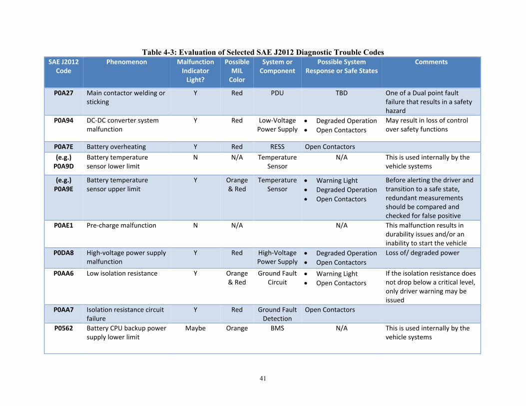
41
Table 4-3: Evaluation of Selected SAE J2012 Diagnostic Trouble Codes SAE J2012
Code Phenomenon Malfunction
Indicator Light?
Possible MIL
Color
System or Component
Possible System Response or Safe States
Comments
P0A27 Main contactor welding or sticking
Y Red PDU TBD One of a Dual point fault failure that results in a safety hazard
P0A94 DC-DC converter system malfunction
Y Red Low-Voltage Power Supply
• Degraded Operation • Open Contactors
May result in loss of control over safety functions
P0A7E Battery overheating Y Red RESS Open Contactors (e.g.)
P0A9D Battery temperature sensor lower limit
N N/A Temperature Sensor
N/A This is used internally by the vehicle systems
(e.g.) P0A9E
Battery temperature sensor upper limit
Y Orange & Red
Temperature Sensor
• Warning Light • Degraded Operation • Open Contactors
Before alerting the driver and transition to a safe state, redundant measurements should be compared and checked for false positive
P0AE1 Pre-charge malfunction N N/A N/A This malfunction results in durability issues and/or an inability to start the vehicle
P0DA8 High-voltage power supply malfunction
Y Red High-Voltage Power Supply
• Degraded Operation • Open Contactors
Loss of/ degraded power
P0AA6 Low isolation resistance Y Orange & Red
Ground Fault Circuit
• Warning Light • Open Contactors
If the isolation resistance does not drop below a critical level, only driver warning may be issued
P0AA7 Isolation resistance circuit failure
Y Red Ground Fault Detection
Open Contactors
P0562 Battery CPU backup power supply lower limit
Maybe Orange BMS N/A This is used internally by the vehicle systems

42
SAE J2012 Code
Phenomenon Malfunction Indicator
Light?
Possible MIL
Color
System or Component
Possible System Response or Safe States
Comments
P0B3B Cell voltage sensor malfunction
N N/A Cell Voltage Sensor
If a safety hazard results • Degraded Operation • Open Contactors
One point of a dual point fault failure that results in a safety hazard
P0B26 Battery over voltage Y Orange & Red
Battery Voltage Sensor
• Warning Light • Open Contactors
Warning light of lower threshold reached; open contactors if safety critical threshold is exceeded.
P0AC2 State of Charge upper limit N N/A Battery Voltage Sensor
N/A Used internally by the vehicle systems
P0AC1 State of Charge lower limit N N/A Battery Voltage Sensor
N/A Used internally by the vehicle systems
P0A7F Battery capacity lower limit
Y Orange N/A
P0B0F Abnormalities in SOC offset
N N/A N/A Used internally by the vehicle systems
P0AC0 Battery current sensor abnormalities in offset
N N/A N/A Information is used internally by the vehicle systems
P06B1 Current sensor power supply malfunction
N N/A Battery Current Sensor
N/A Current sensor for use in estimation of SOC by the BMS
P0602 The program is not written in battery Electronic Control Unit
N N/A Open Contactors If software is missing or the version is not confirmed, the vehicle usually does not start
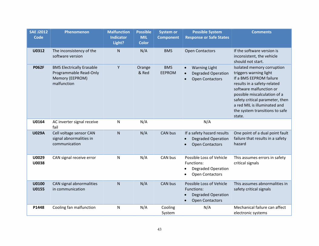
43
SAE J2012 Code
Phenomenon Malfunction Indicator
Light?
Possible MIL
Color
System or Component
Possible System Response or Safe States
Comments
U0312 The inconsistency of the software version
N N/A BMS Open Contactors If the software version is inconsistent, the vehicle should not start.
P062F BMS Electrically Erasable Programmable Read-Only Memory (EEPROM) malfunction
Y Orange & Red
BMS EEPROM
• Warning Light • Degraded Operation • Open Contactors
Isolated memory corruption triggers warning light If a BMS EEPROM failure results in a safety-related software malfunction or possible miscalculation of a safety critical parameter, then a red MIL is illuminated and the system transitions to safe state.
U0164 AC inverter signal receive fail
N N/A N/A
U029A Cell voltage sensor CAN signal abnormalities in communication
N N/A CAN bus If a safety hazard results • Degraded Operation • Open Contactors
One point of a dual point fault failure that results in a safety hazard
U0029 U0038
CAN signal receive error N N/A CAN bus Possible Loss of Vehicle Functions: • Degraded Operation • Open Contactors
This assumes errors in safety critical signals
U0100 U0155
CAN signal abnormalities in communication
N N/A CAN bus Possible Loss of Vehicle Functions: • Degraded Operation • Open Contactors
This assumes abnormalities in safety critical signals
P1448 Cooling fan malfunction N N/A Cooling System
N/A Mechanical failure can affect electronic systems

44
4.4.2.2 Suggested Additional Generic Diagnostic Trouble Codes The analysts preparing the HARAs earlier in this section used those analyses to suggest additional DTCs. Those DTCs are listed in Table 4-4. These 27 DTCs are safety-related and are strong candidates to warrant illuminating a MIL. Note that two of the DTCs are recommended to illuminate an amber rather than red MIL because the associated fault is unlikely to lead to immediate danger, leaving the operator an opportunity to seek service for the affected system. The communication DTCs may be special cases of existing SAE J2012 DTCs.
Table 4-4: Possible Additional Diagnostic Trouble Codes Phenomenon System or
Component Possible
MIL Color
Possible General Industry Safe States
BMS Main Processor CPU Fault BMS Red • Degraded Operation • Open Contactors
BMS Main Processor Memory Fault BMS Red • Degraded Operation • Open Contactors
BMS Main Processor Analogue/Digital Converter Fault
BMS Red • Degraded Operation • Open Contactors
BMS Main Processor Input/Output Connection Fault (Open/Short)
BMS Red • Degraded Operation • Open Contactors
BMS Main Processor Power Supply Fault BMS Red • Degraded Operation • Open Contactors
BMS Main Processor SOH Fault BMS Red • Degraded Operation • Open Contactors
BMS SOC Algorithm Execution Fault BMS Amber • Degraded Operation • Open Contactors
BMS Auxiliary Processor CPU Fault BMS Red • Degraded Operation • Open Contactors
BMS Auxiliary Processor Memory Fault BMS Red • Degraded Operation • Open Contactors
BMS Auxiliary Processor Analogue/Digital Converter Fault
BMS Red • Degraded Operation • Open Contactors
BMS Auxiliary Processor Input/Output Connection Fault (Open/Short)
BMS Red • Degraded Operation • Open Contactors
BMS Auxiliary Processor Power Supply Fault BMS Red • Degraded Operation • Open Contactors
BMS Auxiliary Processor SOH Fault BMS Red • Degraded Operation • Open Contactors
Cell Voltage Sensor Fault Cell Voltage Sensor
Red Open Pre-Charge Contactors
Pack Voltage Sensor Fault Pack Voltage Sensor
Red Open Pre-Charge Contactors

45
Phenomenon System or Component
Possible MIL
Color
Possible General Industry Safe States
Pack Current Sensor Fault Pack Current Sensor
Amber Degraded Operation
Communication Line Fault (Open/Short) BMS Red • Degraded Operation • Open Contactors
Loss of Communication BMS Red • Possible loss of vehicle functions
• Maintain last system state
• Degraded Operation • Open Contactors
Pack Cooling System Fault Battery Pack Cooling
Red • Degraded Operation • Open Contactors
High-Voltage Interlock (HVIL) Fault HVIL Red • Degraded Operation (if vehicle is moving)
• Open Contactors
High-Voltage Interlock Intrusion HVIL Red Open Contactors
Loss of High-Voltage Power RESS Red None
Pre-Charge Contactor Stuck Closed Red None
Main Contactor Chatter PDU Red • Degraded Operation • Open Contactors
Cell Short Circuit Battery Cell Red • Degraded Operation • Open Contactors
Pack Short Circuit Battery Pack Red • Degraded Operation • Open Contactors
Excessive Current Draw Vehicle Systems
Red • Degraded Operation • Open Contactors
Excessive Power Demand Vehicle Systems
Red
Crash Detection Signal Fault BMS Red
4.4.2.3 Diagnostic Trouble Codes of Current Vehicles Original equipment manufacturers publish user and repair manuals that contain DTCs for the purpose of evaluating issues and anomalies in a vehicle’s performance and subsequently repairing the vehicle. The distribution of DTCs was examined in order to gain general insight on the issues OEMs consider most important. Volpe conducted a review of electronic versions of appropriate manuals for three vehicles (two PHEVs and one EV). As a result, Volpe identified the DTCs related to the proper functioning of the RESS and its BMS, and further categorized the distribution of those DTCs by subsystem and component.
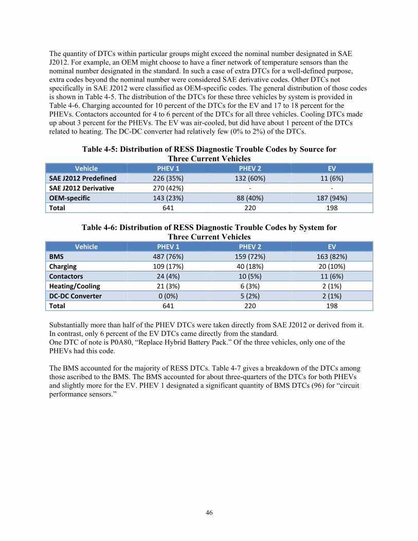
46
The quantity of DTCs within particular groups might exceed the nominal number designated in SAE J2012. For example, an OEM might choose to have a finer network of temperature sensors than the nominal number designated in the standard. In such a case of extra DTCs for a well-defined purpose, extra codes beyond the nominal number were considered SAE derivative codes. Other DTCs not specifically in SAE J2012 were classified as OEM-specific codes. The general distribution of those codes is shown in Table 4-5. The distribution of the DTCs for these three vehicles by system is provided in Table 4-6. Charging accounted for 10 percent of the DTCs for the EV and 17 to 18 percent for the PHEVs. Contactors accounted for 4 to 6 percent of the DTCs for all three vehicles. Cooling DTCs made up about 3 percent for the PHEVs. The EV was air-cooled, but did have about 1 percent of the DTCs related to heating. The DC-DC converter had relatively few (0% to 2%) of the DTCs.
Table 4-5: Distribution of RESS Diagnostic Trouble Codes by Source for Three Current Vehicles
Vehicle PHEV 1 PHEV 2 EV SAE J2012 Predefined 226 (35%) 132 (60%) 11 (6%) SAE J2012 Derivative 270 (42%) - - OEM-specific 143 (23%) 88 (40%) 187 (94%) Total 641 220 198
Table 4-6: Distribution of RESS Diagnostic Trouble Codes by System for
Three Current Vehicles Vehicle PHEV 1 PHEV 2 EV
BMS 487 (76%) 159 (72%) 163 (82%) Charging 109 (17%) 40 (18%) 20 (10%) Contactors 24 (4%) 10 (5%) 11 (6%) Heating/Cooling 21 (3%) 6 (3%) 2 (1%) DC-DC Converter 0 (0%) 5 (2%) 2 (1%) Total 641 220 198 Substantially more than half of the PHEV DTCs were taken directly from SAE J2012 or derived from it. In contrast, only 6 percent of the EV DTCs came directly from the standard. One DTC of note is P0A80, “Replace Hybrid Battery Pack.” Of the three vehicles, only one of the PHEVs had this code. The BMS accounted for the majority of RESS DTCs. Table 4-7 gives a breakdown of the DTCs among those ascribed to the BMS. The BMS accounted for about three-quarters of the DTCs for both PHEVs and slightly more for the EV. PHEV 1 designated a significant quantity of BMS DTCs (96) for “circuit performance sensors.”

47
Table 4-7: Distribution of RESS BMS Diagnostic Trouble Codes by Subsystem for Three Current Vehicles
Vehicle PHEV 1 PHEV 2 EV Temperature Sensors 53 (11%) 52 (33%) 10 (6%) Voltage Sensors 269 (55%) 44 (28%) 131 (80%) SOC/Capacity 0 (0%) 25 (16%) 0 (0%) Internal Resistance Sensor
0 (0%) 12 (8%) 1 (<1%)
Current Sensor 7 (1%) 9 (6%) 7 (4%) Sensor Module 0 (0%) 3 (2%) 0 (0%) Regeneration 0 (0%) 1 (<1%) 0 (0%) Safety Interlock 0 (0%) 0 (0%) 5 (3%) BMS Other 158 (32%) 13 (8%) 9 (6%) Total 487 159 163 The non-SAE J2012 DTCs suggested in the previous subsection were compared to the actual vehicle DTCs. Table 4-8 depicts the correlation between the suggested DTCs and those actually observed in vehicles. While many of the suggested DTCs were implemented in the vehicles, very few were implemented by all three.
Table 4-8: Correlation of Suggested Diagnostic Trouble Codes to Actual Codes Suggested DTC PHEV 1 PHEV 2 EV
BMS Main Processor CPU Fault Memory Fault Analog- Digital Converter Fault Input/Output Connection Fault (Open/Short) Power Supply Fault State of Health Fault
X
BMS Auxiliary Processor CPU Fault Memory Fault Analog- Digital Converter Fault Input/Output Connection Fault (Open/Short) Power Supply Fault State of Health Fault
BMS State of Charge Algorithm Execution Fault X Cell Voltage Sensor Fault Pack Voltage Sensor Fault X X Pack Current Sensor Fault X Communication line Fault (Open/Short) Loss of Communication X X Pack Cooling System Fault X X High-Voltage Interlock Fault X X High Voltage Interlock Intrusion Loss of High-Voltage Power

48
Suggested DTC PHEV 1 PHEV 2 EV
Pre-Charge Contactor Stuck Closed X X X Main Contactor Chatter Cell Short Circuit Battery Pack Short Circuit X Excessive Current Draw X X X
4.5 Results for Communications and Messaging 4.5.1 Operator Needs for Diagnostic and Prognostic Information
Human factors issues related to operator awareness and response to communications and messages from the BMS exist that can, in turn, relate to the safety of a RESS-equipped vehicle. Alternative messaging methods, such as those involving wireless technologies, may hold promise in communicating safety-critical information about the RESS to vehicle owners and operators, as well as advice regarding appropriate responses to malfunctions. In two surveys of U.S. EV owners, RESS safety issues were not mentioned (J. D. Power, 2012; California Center for Sustainable Energy, 2012). Some insight on owner’s perceptions about unmet information needs was gained through discussion threads on online forums for EV owners and through limited formal survey research on owner information needs. These sources suggest that anxiety regarding range and recharging availability are principle owner and driver concerns. The most common were:
• Range sufficiency for current route (topography included) at the current charge level • Recharging options (i.e., cost and location of public stations) when range is known to be
insufficient • Availability at public charging stations
While there is a relative lack of consumer demand for RESS safety information, much of the hardware needed to deliver better RESS safety information is already being included in new vehicle models to serve other functions, primarily to serve infotainment demands.
4.5.1.1 RESS-Specific Information Needs To some extent, all batteries exhibit degradation in charge capacity as a function of such variables as age, number of discharge cycles, depth of discharges, fraction of capacity utilized in recharging, and temperature. Some EV owners may wish to know the extent of this degradation and to have it automatically factored into range estimates. When one current EV manufacturer displayed such information on the instrument panel, it resulted in numerous consumer complaints when the maximum estimated range decreased predictably with age.
4.5.1.2 Operator Warning Needs for RESS Malfunctions The operators’ primary needs for RESS-related information relate to immediate threats to vehicle and occupant safety (e.g., elevated RESS temperatures, exposed high voltage) and other threats to safe operation (e.g., loss of high-voltage traction power). All current EVs and PHEVs generate CAN bus data regarding these hazards and use it to trigger MILs, audible warnings, and text warnings. Drivers should ideally be informed not only about current malfunctions, but also about imminent hazards. Current EVs and PHEVs exhibit warning protocols similar to those described in Table 4-2, with the possible exception of the exit vehicle warning. However, there are inconsistent strategies regarding what issues should be conveyed to the operator. Operators are not always informed when sensor readings depart from the normal operating range, or even when the RESS is due for inspection or replacement.

49
Operators expect a full charge and maximum range when a vehicle is left to charge overnight. Telematics might be used to inform the operator if that is not possible due to improper charging cable connection or even extreme environmental conditions (e.g., extreme temperature). Advanced warnings beyond charge status or hazard in progress (e.g., declining RESS state of health) may require advances in prognostics as described in Appendix K. Warning systems that issue alerts whenever variables deviate from the “guaranteed-safe” range will ensure that users are always warned of malfunctions as early as possible, but they risk exposing operators to so many false-positive warnings that warnings are generally discounted. The design of warning systems has been studied most extensively in aviation; the guiding principles listed below have been adapted from FAA Advisory Circular 25.1322-1 (Federal Aviation Administration, 2010):
• An alerting system should attract the attention of the driver to certain abnormal system conditions and external events that require immediate corrective action, and advise the driver regarding possible measures to address these conditions.
• The alerting system should embody a consistent philosophy for alerting conditions, urgency, prioritization, and presentation. All of these should be explained to drivers through appropriate training materials.
• Use logic-based, integrated alerting systems to ensure that system elements are synchronized and provide the appropriate alert presentation format for each urgency level. This is especially important when multiple warning conditions occur simultaneously. Non-safety-critical warnings may be suppressed until the vehicle has been restored to a safe, stable condition.
The choice of auditory or visual warnings is often conflicted. Table 4-9 shows recommendations for the appropriate situations for the use of each (Deathrage, 1972).
Table 4-9: Recommendations for Warning Format Use auditory presentation if: Use visual presentation if:
The message is simple. The message is complex. The message is short. The message is long. The message will not be referred to later. The message will be referred to later. The message deals with events in time. The message deals with locations in space. The message calls for immediate action. The message does not call for immediate action. The visual system is overburdened, The auditory system is overburdened. The receiving location is too bright or dark
adaptation is required The receiving location is too noisy
In many instances in which malfunction warnings are needed, the recommendations in Table 4-9 will be in conflict; this conflict is usually resolved by providing both types of warnings. Five desired attributes for warnings (Sorensen, 2000) are:
• Specificity, • Consistency, • Accuracy, • Certainty, and • Clarity.

50
Accordingly, OEMs have chosen to warn drivers about RESS malfunctions in much the same way as other malfunctions. At present, the most urgent warnings most vehicles can provide include a flashing red master warning light, a brief text description in the variable message display, and a warning chime or beeper. Only one EV manufacturer included an explicit “Exit Vehicle” icon. Experiments and experience in aviation have shown that the quickest response to such emergencies is achieved through the combined use of a flashing warning light, a text message, and prerecorded verbal warnings employing a one- or two-word problem descriptor with a recommended action, e.g., “TERRAIN – PULL UP.” Many current vehicles already have the necessary hardware installed to produce verbal warnings in reaction to urgent DTCs. In fact, some cars had verbal warnings as early as the 1970s. The challenge lies in developing software to analyze real-time sensor data, accurately predict imminent malfunctions, and present the information to operators in a comprehensible fashion. Vehicles with RESS may be subject to a special warning situation: the possibility of a thermal event or other hazard in an unoccupied vehicle. Such a hazard could pose a threat to human life if it were to occur in an attached garage. BMSs are typically in an “always-on” state so that the vehicle owner can check on charging remotely as well as be warned of both major hazards and more mundane issues, such as the disconnection of a charging cord. Remote warning of dangerously high RESS temperatures could be accomplished by at least three methods:
• Sounding the vehicle horn or theft alarm, • DTCs for overheated components transmitted to a telematics service provider (along with vehicle
ID and GPS coordinates), presuming the service provider could notify the owner and the local fire department,
• Direct message to owner’s phone or “smart house” system. Note that not all phones have a capability to generate an emergency ring-tone that will wake a sleeping owner if the phone is set to silent mode.
While the hardware and “always-on” cellular communications link needed to implement the last two methods are standard on recent EVs and PHEVs, no such remote warnings are known to be implemented at present.
4.5.1.3 Emerging Alternatives for Operator Warnings Most vehicles manufactured since the 1950s come equipped with MILs. From the original four indicator lights (oil pressure, coolant temperature, battery charge, and low fuel), the number has grown to where some vehicles now have more than 20. Anecdotal comments suggest that substantial numbers of drivers ignore or fail to notice illuminated MILs. Such behavior is expected to be more likely when:
• Warnings appear and disappear for no obvious reason, • Warnings appear, but no apparent adverse event ensues, or • Warnings are presented in a cluster of tiny icons with no obvious meaning and/or tiny, unfamiliar
abbreviated text. As electronic sensors, controllers, and actuators proliferate in automobiles, so do the opportunities to provide additional information to the operator about the vehicle’s state of health. Most malfunctions or abnormal operating conditions that can occur will result in the generation of a DTC. The DTC is transmitted over the vehicle’s CAN bus. It is possible that enabled wireless devices on the CAN bus could be programmed to send a message to the operator or a third party or display extensive technical information about the problem. SAE developed the DTC coding convention for queries and responses. The second generation of the On-Board Diagnostics convention is known as OBDII.

51
The recent trend toward providing more extensive infotainment features in cars has brought larger video screens to the center console information displays. Many are now conceivably large enough to display information content as rich as a searchable owner’s manual, although that function is not yet available and would violate NHTSA’s Driver Distraction Guidelines (78 FR 24817, 2013, and NHTSA, 2012) if displayed to the operator of a moving vehicle. OEMs have been offering telematics service subscriptions to new car buyers since the mid-1990s. These subscriptions offer bundled services to customers including remote diagnostics, so that operators at the telematics call centers can read DTCs, explain what they mean to the motorist, provide advice as to appropriate actions, and schedule a service appointment or send a tow truck. Operators can also open doors, start engines, and reboot controllers remotely. OnStar offers users the options of receiving information about malfunctions via an application on their smart phones, or by email, or as part of a monthly overall vehicle health status report. For owners who don’t want any of this technical information, OnStar can also be configured to simply inform a designated General Motors dealer about malfunctions, leaving the task of setting up a service appointment to the staff of that dealer. EV OEMs typically include a wireless modem as standard equipment. The remote telematics functions available on EVs commonly include:
• SOC and estimated range, • Timing of charging, • Notification of completion of charging, and • Preheating or cooling the vehicle while still connected to utility power so as to maximize range.
In addition to charge management, telematics software applications (“apps”) for BEVs commonly provide such functions as:
• Charging station finders, • Vehicle finders, and • Guidance on maximizing range.
Drivers’ needs for diagnostic and prognostic information about vehicular malfunctions are being addressed by several new approaches. These offerings range from free (advertiser-supported) to low-cost apps to subscriptions for a bundle of services including diagnostics. Although the free apps for EVs and the subscription telematics services do not currently include RESS diagnostics, their utility and relatively low-implementation cost should eventually make them more common. Drivers who do not wish to pay subscription costs to maintain telematics service, or who have vehicles that did not include a telematics option at the time the vehicle was built, have other options to access and interpret DTCs. Apps are available that can read and interpret stored DTCs. An interface between the OBDII port and the phone is required. After installing and configuring the app and interface, it can identify and explain any applicable DTC, recall notice, or technical service bulletin. Laptop computers running diagnostic software have been common in commercial repair garages for nearly two decades. In recent years, the interfaces and software have become less expensive. Independent repair garages and enthusiasts who want more information than can be typically displayed on a smart phone can find a variety of packages including both the interface hardware and the software. There are many websites related to automotive diagnostics. Most can be readily found with a search engine and most are free. Many are focused on a specific make and model and include a forum where

52
users can post questions to seek advice from others who may have relevant experience. Others serve the enthusiast community with much more detailed technical information. Some manufacturers also offer their own software and interface cables to provide more advanced diagnostic information. This feature can be especially important for vehicles in which some CAN bus data are encrypted.
4.5.2 Tiered Warning Approach The tiered warning approach discussed in Table 4-2 is an example of the type of operator warning system that could help maintain safety in RESS-equipped automobiles. This system balances the need to avoid distracting and overwhelming drivers with every system anomaly with the requirement to inform operators of hazards that require their attention to maintain safety of the vehicle, its occupants, and others nearby.
4.5.3 Review of Current Messaging Methods Electronic versions of recent EV and PHEV owner’s manuals were obtained. These manuals provide explanations of vehicle functionality and range maximization techniques in a format designed for laymen. As such, the clarity, organization, accuracy, and overall design of a manual provides insight into the information’s content and structure which contributes to the driver’s mental model. Evaluation of the architecture of driver-targeted vehicle information provided by the manufacturer may help identify potential safety and performance concerns resulting from knowledge (or lack thereof) on the part of the operator. Of particular significance is the increase in the number of methods by which the driver is informed and “trained.” As manuals are now released in electronic form, the potential for interactive formats and regular updates is substantial. A key issue for assessing the utility of vehicle warnings was to differentiate between a) warnings used to indicate a subsystem malfunction, and b) warnings used to alert the driver of impending battery charge depletion. The review of manuals has revealed significant overlap between the icons used for these issues in a given vehicle model. In addition, due to the complexity associated with some of these new automation systems, the differences between subsystem malfunctions, automation failures, and automation transitions must be carefully assessed. Considerable diversity exists in EVs and PHEVs as to what kinds of information and RESS malfunction warnings are presented to the driver. All vehicle models reviewed were capable of displaying at least three or four warning icons or messages related to RESS malfunctions in addition to those related to the SOC and range. There is a lack of consistency across manufacturers as to what information about RESS malfunctions is presented to drivers and the icons and messages used to convey it. A trend in the more recently designed cars is to user fewer single-function warning lights and rely more on video message displays. As video displays grow larger, it has become feasible to display more detailed information about malfunctions and what corrective actions to take. Currently, apps for EVs provide substantial information about and control over charging the RESS, but do not provide warnings about RESS faults such as overheating. Finally, the proliferation of new technologies has resulted in the inclusion of so many MILs in the limited instrument panel area that most are now rather small. This necessitates the use of abbreviations (or just initials), the meanings of which may not be obvious to drivers, and increases the chances of their being overlooked.
53
4.6 Results for Testing Requirements 4.6.1 Types of Testing
ISO 26262 recommends that safety validation testing be conducted to confirm that safety goals are achieved. The testing strategy should consist of the validation of the safety measures and the appropriate evaluation of controllability. Appropriate tests using one or more of the following methods could help validate that a RESS meets the Functional Safety Requirements defined through the functional safety processes.
4.6.1.1 Analysis Safety analyses examine the consequences of faults and failures on the functions, behavior, and design of items and elements. They provide information on conditions and causes that could lead to the violation of a safety goal or safety requirement. They also support the identification of additional requirements for verifying that the functional safety concept complies with safety goals and safety requirements, including safety-related vehicle testing. The most widely used analysis methods in the automotive industry are FMEA, FTA, common cause analysis, dependent failure analysis, and, to a lesser extent, the Event Tree Analysis. Most of these methods lend themselves to quantitative as well as qualitative approach. While a quantitative analysis predicts the frequency of failures, qualitative analysis identifies failures but does not predict their frequency.
4.6.1.2 Simulation Simulation relies on modeling of the system or part of the system using mathematical modeling tools. The simulation can assess the system response to faulty inputs or faulty components. Model-based fault injection is often employed when fault injection testing at the hardware product level is particularly difficult. Software simulation usually manipulates critical inputs and parameters. The behavior of the software is checked to ensure that it reacts properly and does not lead to a violation of any safety goal.
4.6.1.3 User Tests under Real World Conditions Long-term tests and user tests under real-world conditions are similar to tests derived from field experience. These use a large sample size of average users as testers and do not have predefined test scenarios. Instead they are performed under conditions of everyday use. These tests are intended to validate system safety under true-life conditions. This type of testing is one of the most relevant test methodologies if a large enough sample size and a long enough test period are used.
4.6.1.4 Fault Injection Tests Some system-safety mechanisms relate to rare events and therefore may not be exercised during normal operation. Fault injection tests are often used in these cases to improve the coverage of the safety requirements. A fault-injection test uses special means to introduce faults into the test object during runtime. This is usually done within the software via a special test interface or specially prepared hardware. For example, a device might be inserted into the input pins of the BMS which can provide a data stream that indicates a particular malfunction under particular conditions (e.g., an over-temperature situation at highway speeds). The system can then be monitored for an appropriate response (i.e., required transition to the correct safe sate, FTT, driver warning, DTC, and data logging).
4.6.1.5 Stress Tests Stress testing is intended to verify correct operation under high operational loads or environmental demands. Tests with high loads are carried out to validate that in the event of random failures the safety mechanism still operates correctly and prevents violations of safety goals.

54
4.6.1.6 Highly Accelerated Life Tests
In this testing method, environmental stresses are applied to the system at levels significantly beyond those expected during normal use in order to accelerate any system fatigue and induce any “weak links” to emerge. System failures that would usually require a long operational time should be exposed. The system behavior is monitored to ensure that the safety mechanisms continue to operate properly and no violations of safety goals occur.
4.6.2 RESS Safety Goal Validation Testing Tests relevant to the safety goal are tabulated in Table 4-10 below. Note that the general thermal event model described in Section 3.2.2.2 is used for reference. Each test procedure would benefit from being developed with a quantitative measure of the following metrics, as appropriate:
• Vehicle controllability • Appropriate fault mitigation • FTT • Issuance of appropriate operator warning • Achievement of appropriate low operating strategy • Setting of appropriate DTC • Accurate and appropriate data logging
Vehicle-specific pass/fail criteria might be developed in a table like that in Appendix I. For example, in a test for the performance of the safety mechanism where the cell temperature exceeds Ta, the pass criteria could be: for the contactors to open within 500 ms, the warning to the driver includes a red light, a chime, and an audible message of Exit Vehicle, the DTC of Battery Overheating should be recorded, and the data logged should show the FTT of 500 ms or less and the temperature measured by the temperature sensor. An exception may be an appropriately analyzed “small” failure (e.g., a single-cell failure in a many-celled RESS). For larger (multi-cell) thermal events, even if subsequently controlled, it could be necessary to keep the vehicle in a disabled state until the damage to the RESS can be evaluated. The test environments described in the table include simulation tools, laboratories, Hardware in the Loop (HIL), and vehicle. Simulation tools include computer tools; examples of simulation tools used in the industry include Matlab and Stateflow. The laboratory environment usually consists of equipment that exercise the system using a specified duty cycle, environmental chambers (e.g., thermal cycling, vibration) and data collection equipment. If a full vehicle is used, it may be necessary to test system responses at speed. For example, testing the efficacy of air cooling may require vehicle motion. Similarly, the fact that HVIL intrusion is unlikely in a moving vehicle may require confirmation that no HVIL warnings are given even at low speeds (e.g., 5 km/h). HIL is methodology that uses simulated sensors and other components or system inputs to validate the system under test. To simulate the inputs, hardware simulators are used. A computer model is used to simulate the test setup, and to control the inputs to the system. System under test actual hardware and software is used. This methodology is very close to actual on-vehicle testing. The full vehicle is the preferred test environment. It should be used whenever practical to validate the safety goals. Representative interfacing systems to the system under test should be used. The specific details of individual tests will need to be developed as technology is developed and designs are finalized. Parameters in the thermal model (e.g., Ta) will need to be determined experimentally. Research will be required to establish robust procedures that adequately assess the effectiveness of safety mechanisms within the range of reasonable design options.
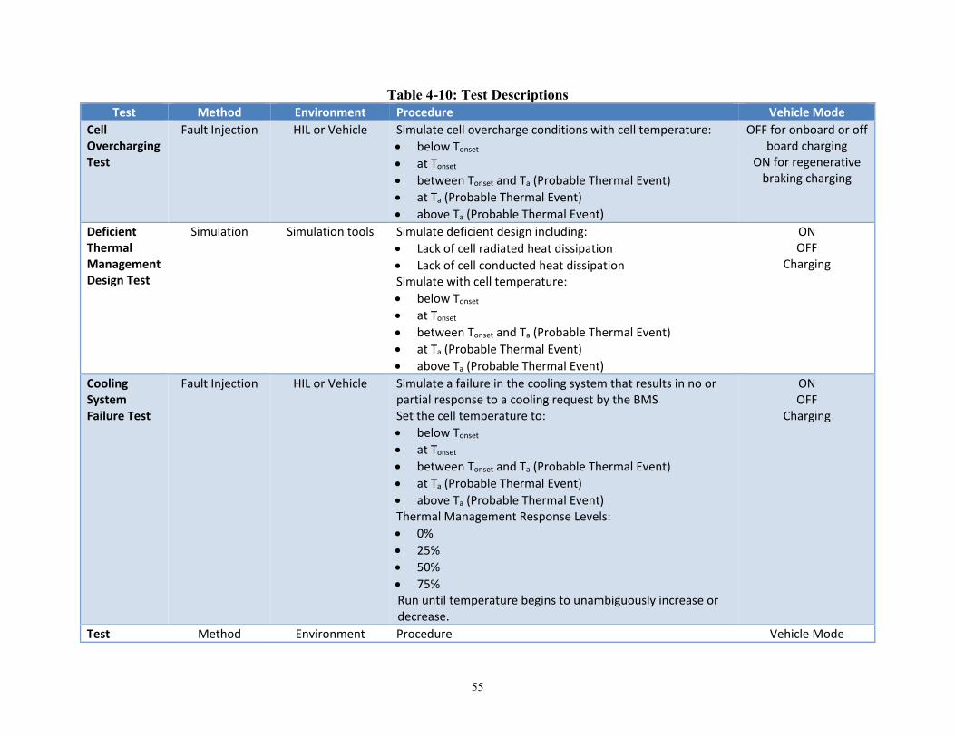
55
Table 4-10: Test Descriptions Test Method Environment Procedure Vehicle Mode
Cell Overcharging Test
Fault Injection HIL or Vehicle Simulate cell overcharge conditions with cell temperature: • below Tonset • at Tonset • between Tonset and Ta (Probable Thermal Event) • at Ta (Probable Thermal Event) • above Ta (Probable Thermal Event)
OFF for onboard or off board charging
ON for regenerative braking charging
Deficient Thermal Management Design Test
Simulation Simulation tools Simulate deficient design including: • Lack of cell radiated heat dissipation • Lack of cell conducted heat dissipation Simulate with cell temperature: • below Tonset • at Tonset • between Tonset and Ta (Probable Thermal Event) • at Ta (Probable Thermal Event) • above Ta (Probable Thermal Event)
ON OFF
Charging
Cooling System Failure Test
Fault Injection HIL or Vehicle Simulate a failure in the cooling system that results in no or partial response to a cooling request by the BMS Set the cell temperature to: • below Tonset • at Tonset • between Tonset and Ta (Probable Thermal Event) • at Ta (Probable Thermal Event) • above Ta (Probable Thermal Event) Thermal Management Response Levels: • 0% • 25% • 50% • 75% Run until temperature begins to unambiguously increase or decrease.
ON OFF
Charging
Test Method Environment Procedure Vehicle Mode

56
Test Method Environment Procedure Vehicle Mode Cell Internal Short Circuit Test
Fault Injection HIL or Vehicle Simulate a short circuit in a single battery cell. Set the cell temperature: • below Tonset • at Tonset • between Tonset and Ta (Probable Thermal Event) • at Ta (Probable Thermal Event) • above Ta (Probable Thermal Event)
ON OFF
Charging
Cell Internal Short Circuit Test: Cascading Failure
Simulation/ Fault Injection
Simulation tools, Laboratory, HIL or
Vehicle
Simulate a cell internal short circuit with associate cascading failure. Select one cell as the starting point. As the cell temperature reaches a predetermined temperature representative of an internal short circuit, simulate a rise in the adjacent cells to mimic a cascading failure.
ON OFF
Charging
Battery Pack Short Circuit Test
Simulation/ Fault Injection
Laboratory, HIL or Vehicle
Simulate a short circuit in one or more battery modules. Set the battery pack voltage appropriately. Set the cell temperature: • below Tonset • at Tonset • between Tonset and Ta (Probable Thermal Event) • at Ta (Probable Thermal Event) • above Ta (Probable Thermal Event)
ON OFF
Charging
External Short Circuit Test
Simulation/Fault Injection
Laboratory, HIL or Vehicle
Simulate an external short circuit where excessive current draw occurs. Set the cell temperature: • below Tonset • at Tonset • between Tonset and Ta (Probable Thermal Event) • at Ta (Probable Thermal Event) • above Ta (Probable Thermal Event)
ON OFF
Charging

57
Test Method Environment Procedure Vehicle Mode
BMS Failure Test
Simulation/ Fault Injection
HIL or Vehicle Simulate relevant BMS failures in: • Charging Controls • Thermal Management Controls • Over Current Detection • Ground Fault Monitoring Set the cell temperature: • below Tonset • at Tonset • between Tonset and Ta (Probable Thermal Event) • at Ta (Probable Thermal Event) • above Ta (Probable Thermal Event)
ON OFF
Charging
Crash Detection Failure Test
Fault Injection HIL or Vehicle Simulate a lost or corrupted crash detection signal ON Charging
HVIL Circuit Failure Test
Fault Injection HIL or Vehicle Simulate an HVIL intrusion while vehicle is moving: • Above 5 km/h • Between 0 and 5 km/h
ON
HVIL Circuit Intrusion Test
Fault Injection HIL or Vehicle Simulate an HVIL intrusion while vehicle is not moving ON OFF
Charging PDU Failure Test
Fault Injection HIL or Vehicle Simulate a main contactor stuck closed or welded condition ON Charging
Ground Fault Test
Simulation/ Fault Injection
HIL or Vehicle Simulate a ground fault condition with isolation resistance: • at pre-determined minimum allowable • below predetermined minimum allowable At vehicle speeds: • above 5 km/h • below 5 km/h • at 0 km/h (not moving)
ON OFF
Charging

58
Test Method Environment Procedure Vehicle Mode PDU Failure Test: Contactors Stuck Open
Fault Injection HIL or Vehicle Simulate a main contactor stuck open condition ( OFF Charging
PDU Failure Test: Contactor Shudder
Fault Injection HIL or Vehicle Simulate a main contactor shudder condition ON OFF
Charging
PDU Failure Test: Unintended Contactor Opening
Fault Injection HIL or Vehicle Simulate a main contactor unintended opening ON Charging
Battery Pack Failure Test: Total Power Loss
Fault Injection HIL or Vehicle Simulate a battery pack failure that results in total loss of power at predetermined low , medium, and high speeds
ON
Battery Pack Failure Test: Partial Power Loss
Fault Injection HIL or Vehicle Simulate a battery pack failure that results in partial loss of power at predetermined low, medium, and high speeds. The pack voltage should simulate the failure of one or more complete battery pack modules.
ON
BMS Failure Test
Simulation/Fault Injection
HIL or Vehicle Simulate relevant BMS failures of: • Temperature signal interpretation and control • HVIL signal interpretation and control • Ground fault interpretation and control • Main contactors control • Crash detection interpretation At vehicle speeds: • above 5 km/h • below 5 km/h
ON

59
5. Summary and Conclusions General fault detection, failure mitigation, degradation strategies, and operator warning strategies described in Sections 4.2 through 4.3.1 would improve the electronics reliability of automotive RESSs. These reflect global best practices (e.g., validation of communications, validation of sensor function, and tiered operator warnings) for assuring overall system integrity and that the component functions and required control actions are supported. The following five sections show the conclusions for each important fault and failure conditions. The last section of this chapter discusses potential future research.
5.1 Cell Overcharging and Over-Discharging 5.1.1 Prevention and Mitigation
The functional safety of the RESS can be endangered by overcharging or over-discharging at the cell, pack, or system level. These conditions should be prevented to the extent reasonable under all operating conditions. Continual evaluation of the health of the BMS, validation of the current and voltage sensors, and the cell balancing system can all help reduce hazardous RESS scenarios. The parameters that characterize the SOH of the RESS must also be reliably understood, updated, and integrated as appropriate into the control functions of the BMS. The core of this process is the accurate estimation and validation of the voltage and SOC of every cell. As the BMS monitors the condition of the RESS, it should have the capacity to recognize improper conditions developing and implement corrective actions. The BMS must communicate to the Vehicle Systems Controller when further charging or discharging is inappropriate. Conditions such as excessive internal impedance or excessive current flow will require mitigation in the form of isolating RESS components (e.g., cell packs or modules) or the entire RESS (via the contactors). If the contactors are determined to be malfunctioning (welding, sticking, chattering), the RESS will need to be able to transition to a safe state within the appropriate fault tolerant time. The contactors will need to function in a time frame on the order of milliseconds in order to provide protection in crash events. Contactor design should consider the potential loss of low-voltage power in hazardous situations and thus be able to transition to open state in case of low-voltage power loss. Overcharging a RESS can lead to internal short circuits and faults that can promote internal heating and thermal events. The hazard severity associated with an over-discharge event may be influenced by RESS chemistry. Many issues with an over-discharged RESS are similar to those from the overcharge scenario, with the fundamental difference that the fault may be latent. The latent fault may manifest itself after the RESS had been recharged to a higher SOC. Since a RESS at that higher SOC would likely be susceptible to a higher severity event if and when it did manifest, the worst-case assessment of the potential hazard of an over-discharged RESS must assume that the potential energy release is equivalent to the energy release associated with overcharge. Thus, an over-discharged RESS must be assumed to be damaged, with the potential for the associated fault to manifest itself at any time. The likelihood of a hazardous event may be elevated by additional charging, particularly in an unattended plug-in charging scenario for an EV or PHEV. The BMS will need to use the estimated SOH of the RESS to continuously optimize the charging cycle profile to prevent overcharging and over-discharging in all operational modes. The BMS must control the charging process and be able to detect a malfunction of the charging system, including charging through regenerative braking. In the case of a ground fault that could result in unsafe charging conditions, the BMS should command the opening of the charging contactors within the established fault tolerant time, currently estimated to be 200 ms, and send a warning to the vehicle operator.

60
5.1.2 Communication and Messaging If the BMS detects that the RESS is overcharged or over-discharged or if it loses the capacity to assess and verify the SOC due to component failure (e.g., sensor fault, processor, or algorithm failure), the system must move to a safe state. This strategy may employ a degraded operation mode (e.g., “limp home mode”) or disconnect the RESS by opening the contactors. In either case, the driver must be alerted to the change in system status in a manner that encourages immediate and appropriate response. Similarly, if the BMS determines that the RESS is in danger of being over-discharged (e.g., excessive power demand or current draw), the operation of the RESS must be degraded or stopped and the driver informed. If an actual over-discharge event is detected, the RESS must be assumed to be significantly damaged. Service is required. An identified over-discharge event of specified magnitude should warrant a “get home” mode for a PHEV or HEV and “limp home” mode for an EV. It should be presumed that the severity of an over-discharge event is the same as for the overcharge case. In the case of a contactor malfunction, the RESS typically defaults to an open contactor state. The driver must be informed of the failure of a main contactor. A driver should also be informed of the failure of a pre-charge contactor as it will eventually result in the loss of function of the RESS and will require service.
5.1.3 Diagnostics and Prognostics Diagnostics covering the safety-related functionality of the BMS or related RESS components and sensors should be instituted with a level of coverage corresponding to the ASIL of the safety goal that is affected. In particular, diagnostics should assess and record anomalies in integrated circuit functions; short or open circuits within the RESS and its sensors; and sensor readings with unreasonable offsets outside the reasonable range or stuck on an identical reading. Diagnostics coverage should support meeting the targets for hardware architectural metrics and the evaluation of the violations of safety goals due to random hardware failures. Diagnostics should be implemented that cover hardware failures— including current, temperature, and voltage sensors, as well as main and pre-charge contactors. When the assessed state of the RESS (SOC or SOH) is entering a dangerous range, DTCs should be set. Prognostics in automotive RESSs generally concern the SOH. Key parameters (e.g., battery cell impedance) must be monitored and kept current in order to appropriately adjust functions such as charging profile. RESS prognostic algorithms may be proprietary, but basic prognostics research is under constant development.
5.1.4 Testing Requirements Table 4-10 offers an array of tests that can be performed to provide confidence that a RESS-equipped vehicle can provide an appropriate level of safety in critical situations. Particularly important for the overcharge and over-discharge conditions are the BMS failure tests, the PDU failure tests, and the cell overcharging tests. These tests should be assessed for appropriate responses across the array of vehicle modes (especially unattended charging and regenerative braking) and cell temperatures. The BMS failure tests for charging controls and over current detection are of particular importance.
5.2 Thermal Management An essential safety goal is the prevention of RESS thermal events. The RESS should be designed to allow for the proper dissipation of heat from the cells under all operating conditions in order to prevent the cells from reaching the thermal runaway condition. It is anticipated that the temperature of cells within the RESS will be maintained within a relatively tight range during normal operation. Excursions beyond this range will likely affect the economic life of the RESS and generate maintenance DTCs before they

61
become a direct safety hazard. Nonetheless, when an unmaintained or damaged RESS experiences rapid temperature changes into dangerous temperature ranges, the BMS must respond appropriately with defined actions. Lost or reduced cooling capacity, including a coolant leak internal to the RESS, can materially affect the ability of the BMS to maintain a safe temperature range.
5.2.1 Prevention and Mitigation of Thermal Excursions The RESS should prevent or detect all cell over-temperature under all operating modes and conditions. The actions required to assure this requirement will likely be more significant whenever the temperature of any cell exceeds Tonset. A primary defense against thermal events is the detection of conditions that will cause rapid heating. Internal (cell or battery pack) or external (high-voltage bus) short circuits are obvious candidates. Any malfunction that allows for an excessive current draw from the RESS can also be dangerous, both in terms of heat generation within the RESS and the risk of over-discharge. In case of current demand by the system that exceeds the capacity of the RESS, the BMS and vehicle systems controller should, if capable, reduce total current draw from the RESS and prioritize its distribution using a predetermined strategy enforced by the vehicle system controller. Otherwise, these conditions must be mitigated by isolating the current from those circuits. If no means exist to identify and isolate specific malfunctioning sub-circuits, the contactors may need to be opened for the entire RESS. In the case of failure of the contactors or current limiters to disconnect the RESS from the vehicle system when necessary, the RESS should transition into a safe state within the established fault tolerant time, currently estimated to be 200 ms. The RESS should measure or correctly estimate the temperature of every battery cell. If the temperature sensor is determined to be faulty and there are no other indications that a thermal event is underway, it may be acceptable to inform the driver of the condition and allow degraded performance sufficient to allow access to appropriate service. The parameters that govern the SOH (e.g., internal impedance of the cell) should be established through experimental correlation of electrical and/or thermal measurements to the change in the parameters due to aging. The BMS should validate the values of these parameters and establish SOH. The output of the BMS algorithms that use cell internal impedance for SOH monitoring should be validated. This may incorporate an understanding of the differences in thermal profile between nominal cells and those with known internal short circuits. The failure or degradation of the cooling system while not a RESS fault per se, must be recognized by the BMS and defined action taken (degraded service or open contactors, as appropriate) until the cooling capacity can be properly serviced and restored. The RESS should mitigate all cell over-temperature under all operating modes and conditions whenever the temperature of any cell exceeds Tonset. In particular, the RESS thermal management system will need to provide a high level of validated protection against any propagation of a cell-level thermal event into a system-level thermal event. The RESS must prevent and mitigate the cascading hazardous effects of cell short circuit into the rest of the system, which will require careful thermal analysis and testing. If after commanding active cooling, the temperature of any cell stays above Tonset for a defined length of time or if the temperature of any cell exceeds Ta, the BMS is to transition the RESS into a safe state within the established fault tolerant time, currently estimated to be 500 ms, and send a warning to the driver. One aspect of the concept to identify and mitigate a potential thermal event is to determine, define, and validate the fault tolerant time for the internal cell short circuits. If the BMS detects any potential or actual cell internal short circuit, it should transition the BMS into a safe state within the established fault tolerant time, currently estimated to be 200 ms, and send a warning to the driver.

62
5.2.2 Communication and Messaging The BMS must warn the driver when conditions indicate the potential for or the existence of a thermal event. In particular, a warning message is to be sent to the driver when the battery cell temperature enters the thermal acceleration region and elevated if it enters the thermal runaway region. A warning message should be sent to the driver when the BMS detects internal or external short circuits that are causing excessive heating or current draw. The driver should be instructed to seek appropriate service. Vehicles with RESS may be subject to a special warning situation: the possibility of a thermal event or other hazard in an unoccupied vehicle. Such a hazard could pose a threat to human life if it were to occur in an attached garage. Fortunately, BMSs are typically either in an “on” state or in a sleep mode from which it can readily transfer into the on state when a command, request, or notification is received. Thus, the vehicle owner can check on charging remotely as well as be warned of both major hazards and more mundane issues such as the disconnection of a charging cord. Remote warning of dangerously high RESS temperatures could be accomplished by at least three methods:
• Sounding the vehicle horn or theft alarm • DTCs for overheated components transmitted to a telematics service provider (along with vehicle
ID and GPS coordinates) presuming the service provider could notify the owner and the local fire department
• Direct message to owner’s phone. Note that not all phones have a capability to generate an emergency ringtone that will wake up a sleeping owner if the phone is set to silent mode.
5.2.3 Diagnostics and Prognostics The temperature sensor should have self-diagnostics to detect failures in its ability to measure the cell temperature and report it correctly to the BMS. In particular, diagnostics should assess and record anomalies in integrated circuit functions, short or open circuits within the RESS and its sensors, and sensor readings with unreasonable offsets, outside the reasonable range, stuck on an identical reading. Diagnostics coverage should support meeting the targets of the hardware architectural metrics and the evaluation of the violations of safety goals due to random hardware failures. Diagnostics should be implemented that cover hardware failures, including current, temperature, and voltage sensors, as well as main and pre-charge contactors. When the assessed temperature of the RESS or its components is entering a dangerous range, DTCs should be set. Temperatures that are too high for nominal operation or too cold for charging should be flagged. States that cause excessive heating (identified short circuits and excessive current draw) should be identified. Finally, the BMS must be aware through diagnostics of any indication of a compromised cooling system including leaking coolant, excessively hot coolant, and malfunctions of the cooling fan or other heat transfer component. Prognostics in automotive RESSs generally concern the SOH. Key parameters (e.g., battery cell impedance) must be monitored and kept current in order to appropriately adjust functions such as charging profile. RESS prognostic algorithms may be proprietary, but basic prognostics research is under constant development.
5.2.4 Testing Requirements Table 4-10 suggests an array of tests that can be performed to provide confidence that a RESS-equipped vehicle can provide an appropriate level of safety in critical situations. Those particularly important for the temperature management functions conditions are the deficient thermal management design test, the cooling system failure test, and the relevant segments of the BMS failure tests.
63
5.3 Release of Hazardous Chemicals The degree of hazard associated with the release of hazardous gases or other chemicals from a Li-ion battery or from an individual Li-ion cell depends on several factors, such as the chemistry of the cells. The chemistry influences the toxicity of substances that might be released. The chemicals could conceivably be benign or could disable the driver. The release of hazardous gases or other chemicals can occur either at the RESS (multi-cell) level or involve only a single cell. Unless demonstrated to be otherwise, the analysis should assume the worst case. Hydrogen gas can form via electrolysis from liquid coolant leaks or other water intrusion into the RESS if a water-based liquid comes in contact with the high-voltage surfaces. Hydrogen gas might also be formed during other scenarios, depending on RESS chemistry and event severity. The formation of hydrogen gas in excess of 18 percent concentration in air is necessary for an explosive event to be possible. Any concentration of hydrogen gas in excess of 4 percent (the lower flammability limit in air) can sustain flames upon ignition. The ignition event is a secondary event independent to the formation of hydrogen gas. Since a coolant leak internal to the RESS can produce lost or reduced cooling capacity, it can both materially affect the ability of the BMS to maintain a safe temperature range and generate liquid water for electrolysis. Therefore, there must be a fail-safe method of fluid sensing inside RESS.
5.3.1 Prevention and Mitigation of Chemical Release While it may be possible for a RESS and BMS to be designed such that the probability of a chemical release due to thermal runaway is small, there is an otherwise necessary functional safety requirement that RESS cells be isolated from the passenger compartment by mechanical means. The passenger compartment should be mechanically isolated from chemical and gas releases (e.g., venting manifolds which assure that by-products are directed away from the passenger compartment or filtration systems to neutralize chemicals.) Designers should also consider to the extent practical the use of nontoxic chemicals (i.e., RESS chemistries which will not produce potentially hazardous gases or liquids, even in a thermal runaway event.) The FSRs to prevent the production of hydrogen gas include features such as:
• Sealing against liquid ingress, • Detection of liquid inside the RESS, • Active control of venting system and/or egress valves, • Protective coating for sensitive electrical areas, and • Active control of the internal RESS cooling system (if applicable).
It is also prudent to minimize the possibility of ignition of hydrogen gas or any other potentially flammable or explosive gas. There are sound design principles that minimize the probability of ignition, such as sealed contactors, robust mechanical interfaces (e.g., connectors, bus bars), and prudent circuit layout design (e.g., separation, tolerances).
5.3.2 Communication and Messaging The BMS needs to warn the driver when conditions exist that indicate the potential for or the existence of a release of hazardous chemicals. In particular, a warning message is to be sent to the driver when there are indications of liquid ingress into the RESS or any indication of a thermal event. The driver should be instructed to seek appropriate service. If plausible, designers might consider methods for notifying responders if the possibility of hazardous chemical release exists.
64
5.3.3 Diagnostics and Prognostics Any liquid ingress detection sensor should have self-diagnostics to detect failures in its ability to detect and correctly report liquid ingress or coolant leak to the BMS. In particular, diagnostics should assess and record anomalies in integrated circuit functions, short or open circuits within the sensors, and sensor readings with unreasonable offsets, outside the reasonable range, stuck on an identical reading. Diagnostics coverage should support meeting the targets of the hardware architectural metrics and the evaluation of the violations of safety goals due to random hardware failures. The BMS must be aware through diagnostics of any indication of a compromised cooling system including leaking coolant, excessively hot coolant, and malfunctions of the cooling fan or other heat transfer component. Prognostics do not apply as directly for the case of hazardous chemical release. Such an event is the result of some other malfunction (coolant leak, water ingress, thermal event) and as such would be handled in the prognostics for avoiding those events.
5.3.4 Testing Requirements Table 4-10 suggests an array of tests that can be performed to provide confidence that a RESS-equipped vehicle can provide an appropriate level of safety in critical situations. Those particularly important for the hazardous chemical release conditions are the relevant segments of the BMS failure tests and possibly the crash detection failure test if the crash detection signal will generate an appropriate warning to operators and responders.
5.4 Electric Shock The electric shock hazard concerns the risk of human contact with lethal voltages (in excess of 60V DC). Such situations are more likely for service technicians and first responders than for vehicle occupants during normal driving conditions. Nonetheless, prudent design should include protection against this hazard both for service technicians and responders as well as for operators who might investigate the RESS during charging or other operation. It should be noted that high-voltage shocks must be prevented; there is no practical or effective “mitigation” action that the vehicle system can effect once a shock has occurred.
5.4.1 Prevention of Electric Shock A fail-safe means for the BMS to stop current flow to and from the RESS, typically in the form of a mechanical or semiconductor contactor, is necessary to protect operators, occupants, and responders from electric shock. Designers may consider incorporating an internal back up power supply for the BMS that keeps it alive after the loss of low-voltage power. During this time, the BMS should be able to bring the RESS to the required safe state and log and store critical system data relevant to the event, preferably in a format that can be interpreted by responders. The RESS should monitor all intrusions into the high-voltage power circuit and is to open the main contactors and disable the high-voltage bus within the established fault tolerant time, currently estimated to be 200 ms, when the HVIL circuit is violated. The BMS is to monitor the ground fault detection system status and the isolation resistance or impedance of the RESS at all time; in case of a fault, the BMS is to transition into a safe state within the established fault tolerant time, currently estimated to be 200 ms. The RESS should implement independent connection methods (contactors) for both HV+ and HV- potentials to the vehicle. There should be appropriate labeling and color coding of high-voltage elements
65
as well as “finger safe” high-voltage connectors. There should be proper consideration for spacing of high-voltage elements (clearance and creepage), and assembly process and environmental variation (temperature, humidity, shock, and vibration). Main contactor faults that result in unintended closing of the main contactors are to be prevented. The risk to crash responders is sufficient that the BMS should open the main contactors when a crash signal is received from the relevant vehicle modules.
5.4.2 Communication and Messaging The BMS needs to warn the driver when conditions exist that indicate the potential for electric shock. While this is exceptionally unlikely while the vehicle is moving, it may be possible when the vehicle is being “operated” (e.g., charged) in a garage. In particular, warning message should be sounded when electric shock is possible, even in the vehicle off or charging modes. The operator should first be instructed to step away from the vehicle and then seek appropriate service from a trained technician. If plausible, designers might consider methods for notifying responders if the possibility of electric shock exists, especially if a ground fault, isolation fault, contactor fault, HVIL fault, or crash fault is detected. As contact with the vehicle is particularly dangerous under such conditions, electronic notification (e.g., via wireless communication) may be especially appropriate for such faults.
5.4.3 Diagnostics and Prognostics Any impedance, ground fault detection, or HVIL sensor should have self-diagnostics to detect failures in its ability to detect and correctly report possible electric shock conditions to the BMS. In particular, diagnostics should assess and record anomalies in integrated circuit functions, short or open circuits within the sensors, and sensor readings with unreasonable offsets, outside the reasonable range, stuck on an identical reading. Diagnostics coverage should support meeting the targets of the hardware architectural metrics and the evaluation of the violations of safety goals due to random hardware failures. Prognostics do not apply as directly for the case of human exposure to electric shock. Such an event is seldom the direct result of some BMS electronic malfunction and as such would be difficult to handle in the prognostics sense.
5.4.4 Testing Requirements Table 4-10 suggests an array of tests that can be performed to provide confidence that a RESS-equipped vehicle can provide an appropriate level of safety in critical situations. Those particularly important for the exposure to electric shock are the HVIL intrusion test, the HVIL circuit failure test, the ground fault test, the relevant segments of the BMS failure tests, and possibly the crash detection failure test if the crash detection signal will generate an appropriate warning to operators and responders.
5.5 Unintended Deceleration A serious malfunction result is the immediate and full loss of torque from the disconnection of the RESS from the vehicle. This would typically result from open contactors, although other faults (e.g., incorrect reporting of SOC) might result in a partial loss of torque. Partial loss of torque is of course less hazardous. Nonetheless, while this malfunction result is most critical for EVs, it should be carefully considered for both HEVs and BEVs. The opening of contactors could result from several faults of electrical or electronic components, including microprocessor control, actuation circuits, wiring and the contactors themselves. Given that the contactors provide the ability to disconnect the RESS from the vehicle as a critical fail-safe element of
66
other hazard mitigation strategies, there is some tension between mitigation of other high level hazards (e.g., thermal event) and the unintended deceleration that results from disconnection of the RESS. An appropriate approach when contactors are opened is therefore to warn the operator and if necessary surrounding vehicles.
5.5.1 Prevention and Mitigation of Unintended Deceleration The RESS should prevent or detect and mitigate all loss of high-voltage power unless it is required to mitigate a significant vehicle hazard. The RESS should inform the vehicle systems controller and the vehicle propulsion system (directly or indirectly) about the loss of high-voltage power, or the intended or unintended disconnection of the high-voltage power from the vehicle high-voltage bus. The unintended opening of the main contactors by the BMS or other vehicle modules should be prevented. In case of any failure resulting in loss of high-voltage power on the high-voltage bus, the RESS should go to the safe state. All RESS electrical subsystem and component failures that lead to loss of the power of the HV bus should be detected and mitigated.
5.5.2 Communication and Messaging The BMS needs to warn the driver when the high-voltage bus is completely or partially compromised. This is particularly important in EVs in which the high-voltage bus is the only source of propulsive power. In such a situation, it may be prudent to inform other drivers as well, such as through automatic engagement of hazard lights. In any condition in which the high-voltage bus is providing power to enable other safety systems (e.g., power steering, airbags) through a DC-DC converter, the operator must be informed immediately. If the vehicle configuration is such that loss of high-voltage power can limit performance (e.g., “limp home mode”), the operator must be informed and encouraged to seek vehicle service immediately.
5.5.3 Diagnostics and Prognostics Any sensor that evaluates the health of the high-voltage bus should have self-diagnostics to detect failures in its ability to detect and correctly report high-voltage malfunctions to the BMS. In particular, diagnostics should assess and record anomalies in integrated circuit functions, short or open circuits within the sensors, and sensor readings with unreasonable offsets, outside the reasonable range, stuck on an identical reading. Diagnostics coverage should support meeting the targets of the hardware architectural metrics and the evaluation of the violations of safety goals due to random hardware failures. The BMS must be aware through diagnostics of any indication of high-voltage power loss, including those implemented by the BMS to mitigate vehicle level hazards. Prognostics do not apply as directly for the case of high-voltage power loss. Such an event would typically be the result of some other malfunction and as such would be handled in the prognostics for avoiding those events.
5.5.4 Testing Requirements Table 4-10 suggests an array of tests that can be performed to provide confidence that a RESS-equipped vehicle can provide an appropriate level of safety in critical situations. Those particularly important for conditions in which high-voltage power is lost are the relevant segments of the BMS failure tests and the battery pack partial and total power loss tests.
5.6 Method Comparison The three hazard analyses exhibited reasonable variability in their characterizations of the vehicle level hazards and their associated significance. Nonetheless, the vehicle-level hazards are substantially the

67
same and vary primarily in the aspects with which they are described and the examples which are chosen. For example, all the analyses considered the generation of hazardous gases, though the focus varied from toxic gases to explosive mixtures of electrolyzed hydrogen and oxygen. Regardless, it was deemed important to prevent their generation but, once generated, to keep them out of the passenger compartment. Thus, all analyses implied the importance of containment integrity, efficient venting away from the passenger compartment, and prevention of thermal events. A key difference between the HazOp and STPA approaches is the characterization of inadequate system performance. HazOp focuses on component function while STPA considers control actions issued (or not issued) by system controllers. At a fundamental level, either approach can be used to describe virtually any problem, though clearly some are more easily depicted by one than the other. Thus, while an insufficient control algorithm is conveniently characterized by STPA and an actuator malfunction is easily defined using HazOp, neither analysis would fail to identify either system issue.

68
References 78 FR 24817 (Apr. 26, 2013). California Center for Sustainable Energy [now called the Center for Sustainable Energy]. (2012). California
Plug-in Electric Vehicle Owner Survey. San Diego: Author. Available at https://energycenter.org/sites/default/files/docs/nav/policy/research-and-reports/California%20Plug-in%20Electric%20Vehicle%20Owner%20Survey%20Report-July%202012.pdf
Christophersen, J., Morrison, J., Morrison, W., & Motloch, C. (2012). Rapid Impedance Spectrum Measurements
for State-of-Health Assessment of Energy Storage Devices. Warrendale, PA: SAE International Journal of Passenger Cars – Electronic and Electrical Systems, 5(1). DOI:10.4271/2012-01-0657.
Coudert, O. (1994). Two-Level Logic Minimization: An Overview. Integration, the VLSI Journal, 17-2, p. 97-
140. Deathrage, Bruce H. (1972). Auditory and Other Sensory Forms of Information Presentation. In H. Van Cott &
R. Kinkaide (eds), Human engineering guide to equipment design. Washington, DC: American Institutes for Research. Retrieved from www.dtic.mil/dtic/tr/fulltext/u2/758339.pdf
Guttowski, S., Weber, S. Hoene, E., John, W., & Reichl, H. (2003, May). EMI in Electric Vehicles. Nuremberg,
Germany: Fraunhofer Institute for Reliability and Microintegration. Available at www.stefan-peter-weber.de/publikationen/pcim03.pdf
Holland, S. W. (2012, January). The Prognosis for Automotive IVHM. First Indo-US Workshop on IVHM and
Aviation Safety, Bangalore, India, January 9 & 10, 2012. Holland, S. W., Barajas, L. G., Salman, M., & Zhang, Y. (2010, October). PHM for Automotive Manufacturing
and Vehicle Applications. 2010 Annual Conference of the Prognostics and Health Management Conference, Portland Oregon, October 10-14, 2010.
International Electrotechnical Commission. (2001). IEC 61882: Hazard and Operability Studies (HAZOP
Studies) - Application Guide, 2001-05, Edition 1.0. Geneva: Author. International Electrotechnical Commission. (2006-2012). IEC 61025, second edition. Fault Tree Analysis (FTA).
Geneva: Author. ISO 26262 Road Vehicles - Functional Safety, Final Draft (FDIS), 2011. J. D. Power (2012, November 8). J. D. Power and Associates 2012 Electric Vehicle Ownership Experience
Study. Westlake Village, CA: Author. Leveson, N. (2012). Engineering a safer world. Cambridge, MA: MIT Press. National Highway Traffic Safety Administration, Visual-Manual NHTSA Driver Distraction Guidelines for In-
Vehicle Electronic Devices, Docket NHTSA-2010-0053, February 15, 2012. Available at www.nhtsa.gov/staticfiles/rulemaking/pdf/Distraction_NPFG-02162012.pdf
SAE J1739: Potential Failure Mode and Effects Analysis in Design and Potential Failure Mode and Effects
Analysis in Manufacturing and Assembly Processes, 1994-07. Warrendale, PA: Society of Automotive Engineers.

69
Soden, M. (2011). ISO 26262 for Safety-Related Automotive E/E Development – Introduction and Concept
Phase. Rome: Intecs SpA. Sorenson, J. (2000). Hazard Warning Systems: Review of 20 Years of Progress. Natural Hazards Review, 119-
125. Thomas, J. (2013). Extending and Automating a Systems-Theoretic Hazard Analysis for Requirements
Generation and Analysis (Ph.D. dissertation). Cambridge, MA: Massachusetts Institute of Technology.

DOT HS 812 556 November 2018