safety instrumented functions
TRANSCRIPT

Safety Instrumented Functions: from risk analysis to PLC implementation
F. Havart, T. Ladzinski, P. Ninin, F. Valentini (BE-ICS)
EDMS: 1977744 1
Control & Safety Solutions workshop – 22th June 2018

2
OutlineSystem Requirements
(Risk Assessment)SIF: from conceptual to
formal definition
PLC Code ImplementationPLC Code Verification/
Validation
Closing remarks
EDMS: 1977744

EDMS: 1977744 3
Risk Assessment
• What are the most relevant outcomes.
• What is the link between Safety Functions and R.A.
• How it shall be presented in practice.

Relevant information from the Study
EDMS: 19777444
SEVERITY
Consequen
ces or cost
of the
related
accident
situation.
A, B, C, D
Risk AssessmentE/E/PE Control Measures Other control measures
RCM-1:Safety action
implemented by the SIS to prevent
the occurrence of one specific
Initiating Event.
RCM-2:Safety action implemented by
the SIS.
RCM-3:Safety action implemented
by the SIS.
M-1: Any other preventive engineering
control, rules or procedure not part of
the SIS.
Initiating Event
(Hazard)
Initiating Event
(Hazard)
Initiating Event
(Hazard)
ACCIDENT SITUATIONUndesirable event that is direct
cause of a physical damages or
property loss.
λ1
M-1
CERN safety Guideline OHS-1-0-1. EDMS: 1144042.
λ2
λ3

EDMS1975444v1 5
Example from a real use case

EDMS1975444v1 6
Typical outcomes from Risk Assessment
Safety Instrumented Functions – Conceptual Description
TYPE 1: “Interlock SOMETHING with SOMETHING ELSE”
AON
BOFF
BON
AOFF
TYPE 2: “Shutdown SOMETHING if Condition is TRUE”
TYPE 3: “Prevent SOMETHING to start until Condition is TRUE”

EDMS1975444v1 7

To be considered @ this stage
EDMS1975444v1 8
o Very good synthesis of hundred of pages of R.A.’s
prescriptions: it summarizes all SIS critical objectives;
o SIF are mostly expressed in natural language: ambiguities are
possible;
o Lack of details about the physical Input / Outputs: how the
conditions shall precisely be computed?
o Different SIF can act on the same actuator (output);
o Many possible ways to code the SIF into PLC code;
o Final system validation can be difficult if the PLC code does
not follow the SIF specification structure.

9
OutlineSystem Requirements
(Risk Assessment)SIF: from conceptual to
formal definition
PLC Code ImplementationPLC Code Verification/
Validation
Closing remarks
EDMS: 1977744

EDMS: 1977744 10
Safety Instrumented FunctionsFrom conceptual to logic design
• What they are for, main purpose of SIF.
• What are the main properties.
• What formalism to use.
• Impact of different design approaches.

EDMS1975444v1 11
Safety Functions definition
Safety Logic Solver
SIF-1
SIF-2
SIF-3
Chain 1
Chain 2
Chain 3

EDMS1975444v1 12
Main desirable properties for SW coding
Completeness:
It should be possible to proof that very risk control measure from Risk
Assessment has been taken into the account.
Correctness & Consistency:
The SIF modelling strategy defining the safety behaviour of the system shall
ensure:
• The construction of a set with the strictly minimum number of SIF to reach
the safety mission of the system.
• The absence of redundant rules.
• The absence of not reachable rules.
• The absence of conflicting rules.
Unambiguity:
A formal language shall be adopted in order to express in a synthetic and not
ambiguous formalism the role of every SIF.

EDMS1975444v1 13
Main desirable properties for SW coding
Safety action uniqueness:
FIS_x
FIS_y
Outputs
…
FIS_x
FIS_y
Outputs
…

EDMS1975444v1 14
Main desirable properties for SW coding
Independency:
FIS_x
FIS_z
Outputs
…
FIS_y
FIS_k
1. Avoid too complex structures
FIS_x FIS_z
Outputs
…FIS_k
2. Avoid cycling rules

EDMS1975444v1 15
Normalization Process for Safety Functions
Interlock A with B if condition1
Shutdown A if condition2
Prevent A to start if condition3
C1 C2 C3 A B
0 0 0 ON OFF
0 0 1 OFF OFF
0 1 0 OFF OFF
0 1 1 OFF OFF
1 0 0 OFF ON
1 0 1 OFF ON
1 1 0 OFF ON
1 1 1 OFF ON
SIF-1: if (cond1==0 & cond2==0 & cond3==0) then A ON
SIF-2: if (cond1==1) then B ON

To be considered @ this stage
EDMS1975444v1 16
o Not all outcomes from R.A. needs to be implemented in safety;
o The added value for implementing a given R.A. outcome as a
SIF shall be demonstrable by the study of the Hazardous
Event failure scenario.
o Specific risk reductions (>10) can be obtained via a SIL rated
SIF but also via several independent layers of protection;
o Include into the SIS design ONLY what is not practicable to
cover otherwise;
o Especially: avoid mix control with critical safety functionalities.
Maintain a clear separation (PROS/CONS … to discuss).

EDMS1975444v1 17
A practical example: ATRAP Experiment

EDMS1975444v1 18
A practical example: ATRAP Experiment
Laser Room Equipment
Local Control Console
Operational Modes

EDMS1975444v1 19
A practical example: SIF Logic Model
Laser states [1..10]
Enclosure positions [1..10]
Door 1 position
Door 2 position
Door Lock 1
Door Lock 2
Laser Shutters

Edms: 1731580 20
A practical example: SIF Logic Model
EDMS1975444v1 21
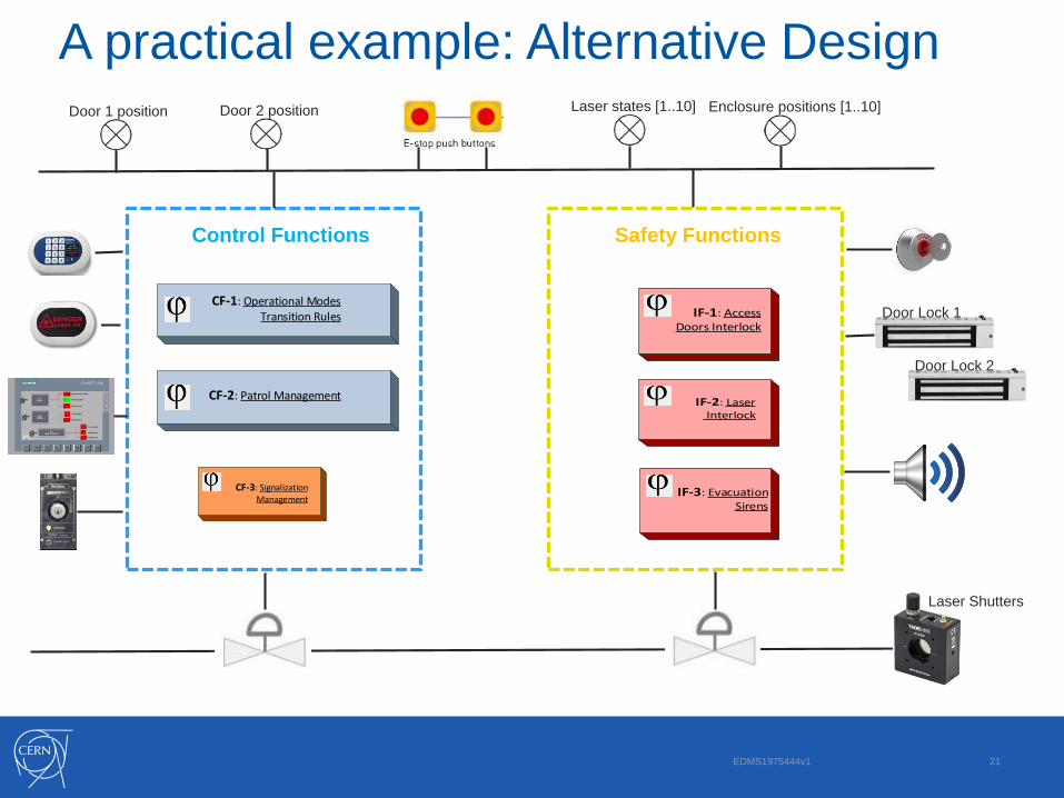
A practical example: Alternative DesignLaser states [1..10] Enclosure positions [1..10]Door 1 position Door 2 position
Control Functions Safety Functions
CF-1: Operational Modes Transition Rules
CF-2: Patrol Management
CF-3: SignalizationManagement
IF-1: AccessDoors Interlock
IF-2: Laser Interlock
Door Lock 1
Door Lock 2
IF-3: Evacuation Sirens
Laser Shutters

22
OutlineSystem Requirements
(Risk Assessment)SIF: from conceptual to
formal definition
PLC Code ImplementationPLC Code Verification/
Validation
Closing remarks
EDMS: 1977744

EDMS: 1977744 23
PLC Code Implementation
• What properties shall have the PLC software.
• How to pass from the SIF logic model to the PLC code.
• What development strategy can be employed

EDMS1975444v1 24
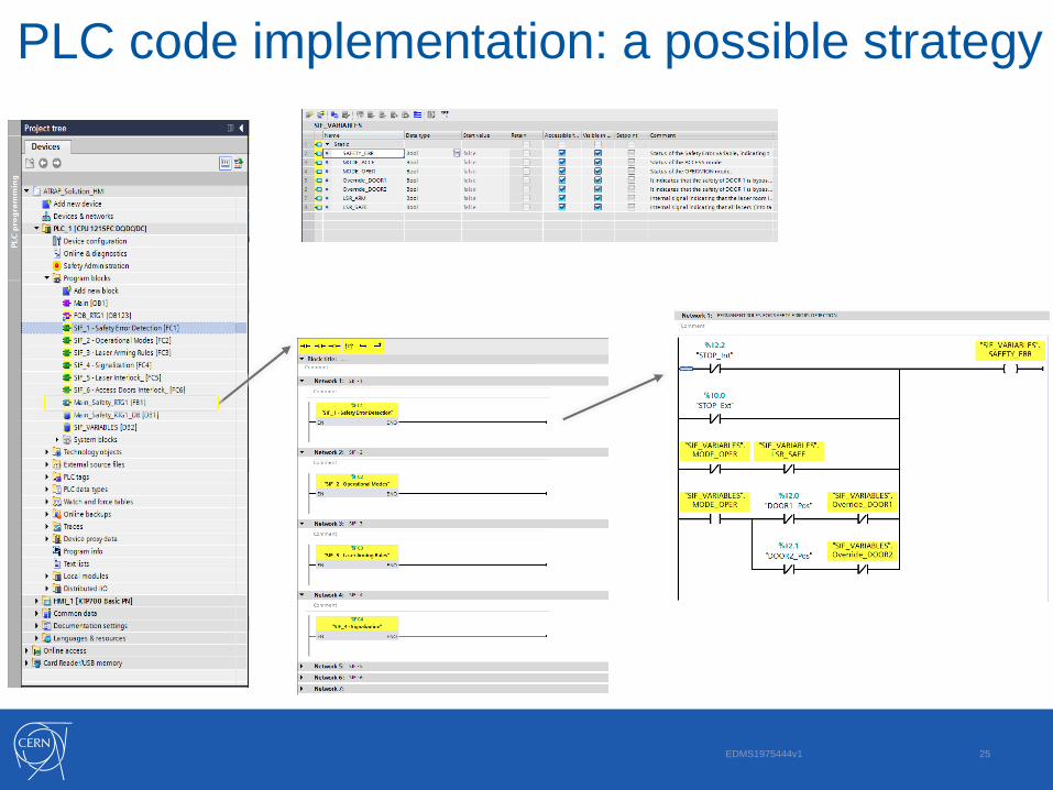
PLC code implementation: main properties
Coherence with specs:
The code’s blocks functionalities shall be clearly identifiable in respect of the
requirements of the functional specification.
Testability:
The code structure shall allow to easy identify relevant test UNITS and make it
easily possible to test them: e.g. every unit shall be testable independently
from the others.
Maintainability:
Different PLC systems developed inside the same organization shall have the
same code structure and the same coding convention.
EDMS1975444v1 25
PLC code implementation: a possible strategy

26
OutlineSystem Requirements
(Risk Assessment)SIF: from conceptual to
formal definition
PLC Code ImplementationPLC Code Verification/
Validation
Closing remarks
EDMS: 1977744

EDMS: 1977744 27
PLC Code Verification & Validation
• How to define PLC software unit tests?
• How to ensure that unit tests are relevant for the validation of a
specific SIF?
• How to ensure the system does what it is supposed to?
• How to estimate the quality of the tests: test coverage?
• Practical tests execution.

EDMS1975444v1 28
PLC code V & V: main properties

EDMS1975444v1 29
PLC code V & V: main properties
Test Criterion:Verify FIS outputs for all possible events triggering the FIS
interlock actions.
𝝎 ∶
TEST CASE
MODEL
TEST
CRITERION
TEST CASE
RESTRICTIONS
TEST CASES
GENERATION
ALGORITHM

EDMS1975444v1 30
PLC code V & V: main properties
Test Instances auto-generated by MATLAB:
PROFINET
Siemens PLC S7-1500
Siemens SIMBA BoxTIA Portal
Test Control PC
TCP/IP
PLC Test
Script
Unit Test Report
(SIF blocks)

31
OutlineSystem Requirements
(Risk Assessment)SIF: from conceptual to
formal definition
PLC Code ImplementationPLC Code Verification/
Validation
Closing remarks
EDMS: 1977744
Closing Remarks
SIL VERIFICATION
• FTA approach: typically thousands of nodes are needed to model a
complex systems.
• Large usage of approximating hypotheses: failure rates of
components, probability distribution, calculations, system design.
• Impact of these approximations on final results is not easily
accountable, but it grows with the complexity of the system.
EDMS: 1977744 32

Closing Remarks
EDMS: 1977744 33

Closing Remarks
EDMS: 1977744 34

Closing Remarks
EDMS: 1977744 35

Closing Remarks
KEYPOINTS FOR COMPLEX SYSTEMS DESIGN
• Keep a clear separation between Safety and Standard control.
• Make the safety part as simple as possible: do not include in the
SIS functionalities what can be done in standard if NO added
value. It makes easy to proof SIL and to validate SIS.
• Norm 61511 is helpful for systems of reduced/average scale,
however for complex systems nuclear norm 61513 can bring real
added value focusing more on other aspects than SIL:
Usage of redundancy and diversity of SIS devices;
Prescriptions against external aggressions;
Guidelines to avoid common causes & modes of failures.
EDMS: 1977744 36

THANK YOU FOR YOUR ATTENTION
Any Questions?
EDMS: 1977744 37
