safety in motion bzfm v7
TRANSCRIPT

safety in motion
Stromag Dessau
BZFM V7BZFM V7

Electromagnetic Spring Applied BrakeProtection IP 44 BZFM V7 Stromag Dessau
safety in motion
Spring Applied Brake BZFM V7 – 01.06.2009 1
Brake series for mounting to standard electric motors as general industrial brake.
Standard Features Coil Body with coil thermal class 155 (F), special surface protection Friction lining carrier Rigidly fixed on motor shaft via fitting key, zinc coated Friction Lining Axially flexible friction pads in the friction lining carrier allow
a high tolerance when fixing friction lining carrier on the shaft thus simplifying the mounting on brake assembly
Adjusting Ring a simple reduction of the brake torque up to a value of 55 % is possible Adjusting screws several possible screw – type wear re-adjustment Armature Plate Special protection: nitrocarburated Brake disc Special protection: nitrocarburated Fixings screws included in delivery, zinc coated Flying Leads 0,5 metre long
Optional Extra’s Hand release lever
Micro switch to monitor switching states (from size 6,3) Micro switch for wear monitoring (from size 6,3)
Switching modules
Half wave Full wave Quick switching units
Applications

Electromagnetic Spring Applied BrakeProtection IP 44 BZFM V7 Stromag Dessau
safety in motion
Spring Applied Brake BZFM V7 – 01.06.2009 2
Advantages
Torque range 2,7 -380 Nm.
Simple assembly to motor, no dismantling of brake required.
Completely pre-mounted and adjusted.
All surfaces are corrosion resistant.
Compact, simple construction with high heat capacity.
The fitted friction pads form an interrupted friction face thus resulting in good air circulation and heat dissipation.
Less wear due to high stability of the friction material.
Delivered in run-in and torque tested condition.
Simple torque adjustment with adjusting ring.
As a standard, prepared for hand lever mounting – retrofit possible without any problems.
Free from axial loads when braking and running.
Suitable for vertical mounting, please consult Stromag Dessau GmbH.
Proven reliable design.
Protection IP 44 by rubber collar and seal ring on through-going shaft
Voltages available
Standard 24 V DC, 103 V DC, 190 V DC and 207 V DC, 240 V DC Other voltages on request. Coils available to suit: AC – supplies with Half and Full wave rectification. We suggest the following alternative - Customer to take standard voltage with rectifier which Stromag Dessau can provide.

Electromagnetic Spring Applied BrakeProtection IP 44 BZFM V7 Stromag Dessau
safety in motion
Spring Applied Brake BZFM V7 – 01.06.2009 3
Designation of individual components 01 Coil body 02 Armature disc 03 Brake disc (counter friction face) 04 Friction lining carrier 05 Friction lining 06 Coil 07 Spring 12 Adjusting ring 13 Seal ring 14 Rubber collar
Brake operation
The brake BZFM V7 is a spring loaded electromagnetic double-face brake which brakes without current and is released electromagnetically. The coil body (01) contains a coil (06) which is potted with an synthetic resin compound in accordance with thermal class 155, (max. limit of temperature 155°C). If the coil (06) is not excited, the springs (07) which are situated in the internal and external pole, press the armature disc (02) against the floating formatted friction lining carrier (04). Thus is firmly clamped between the torsion-protected armature disc (02) and the brake disc (03) and thus prevented from rotating. The braking effect is transmitted from the friction lining via the carrier with friction lining (04) and a feather key to the shaft.
06
01
02
04
12
03
07
05
13
14

Electromagnetic Spring Applied BrakeProtection IP 44 BZFM V7 Stromag Dessau
safety in motion
Spring Applied Brake BZFM V7 – 01.06.2009 4
If the coil (06) is connected to a direct voltage as specified on the identification plate or about a Stromag rectifier set to a alternating voltage, the magnetic force will draw the armature disc (02) to the coil body (01) against the spring pressure (07). The friction lining is released, the braking is cancelled and the brake is released.
Micro Switch standard option available from size 6,3 up to 25, Inboard Proving Switch, one common contact, one normally open contact and one normally closed contact.
This can be interlocked with motor contactor for parking brake duty, i.e. brake release before starting motor.
Brake termination Flyaway leads, usually 0,5 meter long. Please note that when the brake is electrically connected to an AC motor and switched on the AC side, care must be taken so that the load does not drive back into the motor and generate a voltage that may hold the brake off, i.e. in hoist and lift applications. If in doubt please contact the Stromag Dessau GmbH.
Emergency release by means of hand lever release
Optionally the brake can be equipped with a hand release lever allowing the manual release by means of a hand lever. The brake is prepared for hand lever mounting –
retrofit is possible without any problems.
Brake flange Counter-friction face mounted to the motor on B-side.
Adjusting ring A simple reduction of the brake torque up to a value of 55 % is possible.
Adjusting screws The airgap of the brake can be re-adjusted several times until the lower wear limit of the friction lining is achieved.
Example of designation
BZFM 10 V7 103 VDC 38H7 MS
Brake typeBrake sizeBrake variantNominal voltageBore diameter with key wayWith micro switch


Electromagnetic Spring Applied BrakeProtection IP 44 BZFM V7 Stromag Dessau
safety in motion
Spring Applied Brake BZFM V7 – 01.06.2009 5
Calculations
Full Load Torque = FLT Load torque = Nm
Torque = Nm Power = kW
Constant = 9550 Speed = rpm
Initial Torque, size of brake = FLT x Factor (25% - 200%)
Calculating Maximum Stops per Hour using Braking Tables Example:
Motor = 4 kW; 3000 rpm J = Total inertia of Load + motor = 0,0245 kgm
2
ML = Load Torque = 20 Nm MSN = Brake Torque = 100% FLT
Motor FLT = kW x 9550
rpm = 4 x 9550
3000 = 12.7 Nm
Brake selection = BZFM 10 V7 (113 Nm)
KJ per switching
= J x n2
182000 x
MSN MSN ± ML
= 0,0245 x 30002
182000 x
113 113 + 20
= 1,21 x 113 133
2,06 kJ per switching
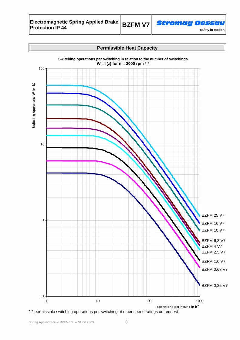
From BZFM V7 Table “Permissible heat capacity”, at 3000 rpm BZFM V7 Brake will stop approx. 350 times per hour.
To Calculate Stopping Time
Stopping Time = J x rpm 9.55 x (MSN ± ML)
Example:
Brake = BZFM 10 V7 (113 Nm) Motor = 4 kW; 3000 rpm
J = Total inertia of load + motor = 0.0245 kgm2
TL = Load Torque = 20 Nm
Stopping Time = 0.0245 x 3000 9.55 x (113+20)
Stopping Time = 58 ms + Brake response time
Electromagnetic Spring Applied BrakeProtection IP 44 BZFM V7 Stromag Dessau
safety in motion
Spring Applied Brake BZFM V7 – 01.06.2009 6
Permissible Heat Capacity
Switching operations per switching in relation to the number of switchings W = f(z) for n = 3000 rpm * *
* * permissible switching operations per switching at other speed ratings on request
0,1
1
10
100
1 10 100 1000
operations per hour z in h-1
Switc
hing
ope
ratio
ns W
in
kJ
BZFM 25 V7
BZFM 16 V7
BZFM 10 V7
BZFM 6,3 V7 BZFM 4 V7BZFM 2,5 V7
BZFM 1,6 V7
BZFM 0,63 V7
BZFM 0,25 V7

Electromagnetic Spring Applied BrakeProtection IP 44 BZFM V7 Stromag Dessau
safety in motion
Spring Applied Brake BZFM V7 – 01.06.2009 7
Our Address
Stromag Dessau GmbH Dessauer Str. 10 D-06844 Dessau-Roßlau Tel.: +49 (340) 2190-203 Fax: +49 (340) 2190-201 E-Mail: [email protected] Internet: http://www.stromag-dessau.de