safety function: cable pull switch application...
TRANSCRIPT
Application Technique
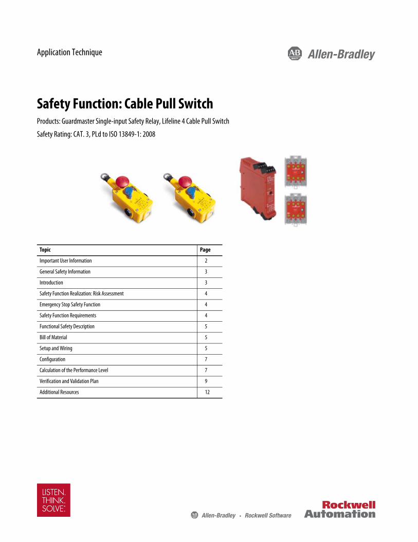
Safety Function: Cable Pull SwitchProducts: Guardmaster Single-input Safety Relay, Lifeline 4 Cable Pull Switch
Safety Rating: CAT. 3, PLd to ISO 13849-1: 2008
Topic Page
Important User Information 2
General Safety Information 3
Introduction 3
Safety Function Realization: Risk Assessment 4
Emergency Stop Safety Function 4
Safety Function Requirements 4
Functional Safety Description 5
Bill of Material 5
Setup and Wiring 5
Configuration 7
Calculation of the Performance Level 7
Verification and Validation Plan 9
Additional Resources 12

Safety Function: Cable Pull Switch
Important User Information
Read this document and the documents listed in the additional resources section about installation, configuration, and operation of this equipment before you install, configure, operate, or maintain this product. Users are required to familiarize themselves with installation and wiring instructions in addition to requirements of all applicable codes, laws, and standards.
Activities including installation, adjustments, putting into service, use, assembly, disassembly, and maintenance are required to be carried out by suitably trained personnel in accordance with applicable code of practice.
If this equipment is used in a manner not specified by the manufacturer, the protection provided by the equipment may be impaired.
In no event will Rockwell Automation, Inc. be responsible or liable for indirect or consequential damages resulting from the use or application of this equipment.
The examples and diagrams in this manual are included solely for illustrative purposes. Because of the many variables and requirements associated with any particular installation, Rockwell Automation, Inc. cannot assume responsibility or liability for actual use based on the examples and diagrams.
No patent liability is assumed by Rockwell Automation, Inc. with respect to use of information, circuits, equipment, or software described in this manual.
Reproduction of the contents of this manual, in whole or in part, without written permission of Rockwell Automation, Inc., is prohibited.
Throughout this manual, when necessary, we use notes to make you aware of safety considerations.
Labels may also be on or inside the equipment to provide specific precautions.
WARNING: Identifies information about practices or circumstances that can cause an explosion in a hazardous environment, which may lead to personal injury or death, property damage, or economic loss.
ATTENTION: Identifies information about practices or circumstances that can lead to personal injury or death, property damage, or economic loss. Attentions help you identify a hazard, avoid a hazard, and recognize the consequence.
IMPORTANT Identifies information that is critical for successful application and understanding of the product.
SHOCK HAZARD: Labels may be on or inside the equipment, for example, a drive or motor, to alert people that dangerous voltage may be present.
BURN HAZARD: Labels may be on or inside the equipment, for example, a drive or motor, to alert people that surfaces may reach dangerous temperatures.
ARC FLASH HAZARD: Labels may be on or inside the equipment, for example, a motor control center, to alert people to potential Arc Flash. Arc Flash will cause severe injury or death. Wear proper Personal Protective Equipment (PPE). Follow ALL Regulatory requirements for safe work practices and for Personal Protective Equipment (PPE).
2 Rockwell Automation Publication SAFETY-AT088B-EN-P - May 2016

Safety Function: Cable Pull Switch
General Safety Information
Contact Rockwell Automation to learn more about our safety risk assessment services.
Safety Distance Calculations
Non-separating safeguards provide no physical barrier to prevent access to a hazard. Publications that offer guidance for calculating compliant safety distances for safety systems that use non-separating safeguards, such as light curtains, scanners, two-hand controls, or safety mats, include the following:
EN ISO 13855:2010 (Safety of Machinery – Positioning of safeguards with respect to the approach speeds of parts of the human body)
ANSI B11:19 2010 (Machines – Performance Criteria for Safeguarding)
Separating safeguards monitor a moveable, physical barrier that guards access to a hazard. Publications that offer guidance for calculating compliant access times for safety systems that use separating safeguards, such as gates with limit switches or interlocks (including SensaGuard™ switches), include the following:
EN ISO 14119:2013 (Safety of Machinery – Interlocking devices associated with guards - Principles for design and selection)
EN ISO 13855:2010 (Safety of Machinery – Positioning of safeguards with respect to the approach speeds of parts of the human body)
ANSI B11:19 2010 (Machines – Performance Criteria for Safeguarding)
In addition, consult relevant national or local safety standards to assure compliance.
Introduction
This safety function application technique explains how to wire and configure two cable pull switches to a Guardmaster™ single-input safety relay. When one of the two cable pull switches is pulled, the relay responds by opening its safety contacts and removing 24V DC from the coils of the two 100S safety contactors. The 100S contactors open and remove power from the hazardous motion. The hazardous motion coasts to a stop (stop category 0).
IMPORTANT This application example is for advanced users and assumes that you are trained and experienced in safety system requirements.
ATTENTION: Perform a risk assessment to make sure that all task and hazard combinations have been identified and addressed. The risk assessment can require additional circuitry to reduce the risk to a tolerable level. Safety circuits must consider safety distance calculations, which are not part of the scope of this document.
ATTENTION: While safety distance or access time calculations are beyond the scope of this document, compliant safety circuits must often consider a safety distance or access time calculation.
Rockwell Automation Publication SAFETY-AT088B-EN-P - May 2016 3

Safety Function: Cable Pull Switch
Safety Function Realization: Risk Assessment
The required performance level is the result of a risk assessment and refers to the amount of the risk reduction to be conducted by the safety-related parts of the control system. Part of the risk reduction process is to determine the safety functions of the machine. In this application, the performance level required (PLr) by the risk assessment is Category 3, Performance Level d (CAT. 3, PLd), for each safety function. A safety system that achieves CAT. 3, PLd, or higher, can be considered control reliable. Each safety product has its own rating and can be combined to create a safety function that meets or exceeds the PLr.
Emergency Stop Safety Function
This application technique includes one safety function: the removal of power from the hazard when the safety system detects that the cable pull switch has been actuated.
ISO 13849-1 directs that when devices are connected in series, such as the two cable pull switches in each segment in this safety function application, the function of each device is evaluated as a separate safety function.
In this safety function application, the two cable pull switches are evaluated as two identical E-stop safety functions.
Safety Function Requirements
Pulling any one of the two series-wired cable pull switches stops and prevents hazardous motion by removal of power to the motor. When the cable pull switches are reset, hazardous motion and power to the motor does not resume until a secondary action (start button depressed) occurs. Faults at the switch, wiring terminals, or safety controller are detected before the next safety demand. This emergency stop function is complementary to any other safeguards on the machine and does not reduce the performance of other safety-related functions. The safety function in this example is capable of connecting and interrupting power to motors rated up to 9A, 600V AC. The safety function meets the requirements for Category 3, Performance Level d (CAT. 3, PLd), per ISO 13849-1 and control reliable operation per ANSI B11.19.
From: Risk Assessment (ISO 12100)
1. Identification of safety functions
2. Specification of characteristics of each function
3. Determination of required PL (PLr) for each safety function
To: Realization and PL Evaluation
4 Rockwell Automation Publication SAFETY-AT088B-EN-P - May 2016

Safety Function: Cable Pull Switch
Functional Safety Description
Two cable pull switches are connected in series to the Guardmaster single-input safety relay. One channel runs through the two cable pull switches between pulsed output S11 and input S12, and the other channel between pulsed output S21 and input S22. The safety relay monitors the pulse stream at each input to confirm that each cable pull switch channel is in a proper state. When any cable pull switch is pulled, these two circuits are interrupted. The relay responds to this circuit interruption by opening its safety contacts (13…14 and 23…24), and de-energizing the coils of K1 and K2. With power removed, hazardous motion coasts to a stop (stop category 0). Hazardous motion cannot be restarted until the cable pull switches are released and the reset button is pressed and released.
To confirm the proper state of the two 100S safety contactors before permitting a start or reset, 24V DC is run in series through an N.C. auxiliary contact on each 100S contactor to the Reset button of the safety relay. If a safety contact of one or both 100S contactors is welded closed, the corresponding auxiliary N.C. contact is held open, breaking the 24V DC circuit to the Reset button.
The safety relay in this application is configured for Automatic/Manual Start. When the inputs of the cable pull switch are in the proper state, and the two 100S contactors are properly de-energized, turning the Reset button of the cable pull switch results in the safety relay energizing the two 100S safety contactors.
Bill of Material
This application technique uses these products.
Setup and Wiring
For detailed information on how to install and wire, refer to the publications listed in the Additional Resources.
System Overview
The pulsed outputs of the Guardmaster single-input safety relay (terminals S11 and S21) are run separately through the contact strings of the two cable pull switches (cable pull 1 to cable pull 2) to input terminals S12 and S22, respectively. This configuration enables the safety relay to detect a loose wire, a short to 24V DC, a short to GND, and cross-channel faults. There is the possibility that a contact in one of the cable pull switches could fail closed and that this failure could be masked by the operation of the other cable pull switch. For this reason, the two cable pull switches in the string are calculated as having a Category 3 structure.
The safety relay responds to the inputs of the cable pull switches and detected circuit faults of the cable pull switches by opening its safety contacts (13…14 and 23…24), thus de-energizing the coils of K1 and K2. The safety relay cannot be reset until the cable pull switch is released, or the fault is corrected. In some cases, the cable pull switch must be pulled and released before the safety relay can be reset. After some faults, before it can be reset, the safety relay must be power-cycled once the fault is cleared.
Cat. No. Description Quantity
440E-L13137 440E emergency stop device – Lifeline™ 4 cable pull switch 2
440R-S12R2 Guardmaster single-input safety relay, one dual-channel universal input, one N.C. solid-state auxiliary output 1
100S-C09ZJ23C Modular control system 100S-C safety contactor, 9A, 24V DC 2
Rockwell Automation Publication SAFETY-AT088B-EN-P - May 2016 5

Safety Function: Cable Pull Switch
The safety relay monitors itself for any internal faults. When a fault is detected, the safety relay responds by opening its safety contacts (13…14 and 23…24) and de-energizing the coils of K1 and K2. Some internal faults can be cleared by power-cycling the safety relay. In other cases, the safety relay must be replaced.
The safety relay monitors the 100S contactors for welded contacts via two N.C. contacts in series, one from each 100S contactor, in its reset circuit. If a contact of a 100S contactor is welded, the N.C. contact is held open, which breaks the reset circuit.
Electrical Schematic
A1 A2
SIS11
S12
S21
S22
S34
13
23 24
24V 0V
M
K1
K2
K1
K2
0
AM
MM
Reset
WIRING
External SwitchedStop/Start Circuit
Y32
14
Statusto PLC
Statusto PLC
Statusto PLC
Statusto PLC
K1a K2a
Status to PLC
K1b
K2b
Statusto PLC
11 11 1212
21 2122 22
33 3433 34
A1 A2
A1 A2
24V 0V Wiring
Reset
External Switched Stop/Start Circuit
Status to PLC
Status to PLC
Status to PLC
Status to PLC
Status to PLC
Status to PLC
6 Rockwell Automation Publication SAFETY-AT088B-EN-P - May 2016

Safety Function: Cable Pull Switch
Configuration
Follow these steps to configure the relay.
1. With power off, turn the rotary switch to position 0, and apply power.
The PWR status indicator flashes red.2. Turn the rotary switch to the desired position.
The IN 1 status indicator blinks to acknowledge the new setting. The position is set when the PWR status indicator is solid green.
3. Lock in the configuration by cycling power to the relay.The configuration must be confirmed before operation. Use the white space on the front of the device to record the unit setting.
Calculation of the Performance Level
When properly implemented, each of the two E-stop safety functions of this safety system (emergency stop of hazardous motion that is initiated by the cable pull switch) can achieve a safety rating of Category 3, Performance Level d (CAT. 3, PLd), according to ISO 13849-1: 2008, as calculated by using the Safety Integrity Software Tool for the Evaluation of Machine Applications (SISTEMA).
Rockwell Automation Publication SAFETY-AT088B-EN-P - May 2016 7

Safety Function: Cable Pull Switch
The individual subsystem values for one of the E-stop functions are shown in the graphic.
The entire E-stop project can be modeled as follows.
The SISTEMA values and the block diagram model are the same for the second E-stop function.
Because the cable pull switches are electromechanical devices, certain data must be provided for evaluation of expected performance, which need not be provided for electronically based devices, such as a safety relay, when used in a safety function.
This data includes:• Fault Exclusion (FE)• Mean Time to Failure, dangerous (MTTFd)• Diagnostic Coverage (DCavg)• Common Cause Failure (CCF)
The functional safety evaluations of the electromechanical devices include the following:• How frequently they are operated• Whether they are effectively monitored for faults• Whether they are properly specified and installed
Because the cable pull switches are electromechanical devices, a fault exclusion must be considered when calculating a safety rating. A fault exclusion subsystem is added to the SISTEMA calculation to reflect this. EN-ISO 13849-2:2012, Annex D, allows a fault exclusion for mechanical aspects of emergency stop (complementary) devices in accordance with IEC 60947-5-5, when the estimated maximum number of cable pull switch (E-stop) operations is not excessive. Such an
Cable Pull 1 S1
Fault Exclusion
GSR SI
100S-C K1
Cable Pull 1 S1
100S-C K2
Subsystem 1 Subsystem 2 Subsystem 3 Subsystem 4
Input Logic Output
Cable Pull 1 S1
Cable Pull 1 S2
Fault Exclusion
Guardmaster Single-input Safety Relay
100S-C K1
100S-C K2
Subsystem 1 Subsystem 2 Subsystem 3 Subsystem 4
8 Rockwell Automation Publication SAFETY-AT088B-EN-P - May 2016

Safety Function: Cable Pull Switch
allowed fault exclusion has no effect on the Category or Performance Level achieved by the cable pull switch (E-stop) safety functions. To reflect this configuration in the SISTEMA project calculations, the Category and Performance Level of the fault exclusion subsystem were manually entered as Category 4 and Performance Level e.
SISTEMA calculates the MTTFd by using B10d data for the electromechanical devices provided in the Rockwell Automation SISTEMA library, along with the estimated frequency of use, entered during the creation of the SISTEMA project. In this application, the estimated frequency of use for each cable pull switch was 365 times a year.
The DCavg (60%) for the cable pull switch (E-stop) was entered manually to take into account that they are connected in series. Masking, due to series connection, reduces the ability of the system to detect faults.
The DCavg (99%) for the contactors is selected from the Output Device table of ISO 13849-1:2006, Annex E, Direct Monitoring.
The CCF value was generated by using the scoring process outlined in Annex F of ISO 13849-1. The complete CCF scoring process must be performed when actually implementing an application. A minimum score of 65 must be achieved. A CCF of 65 was entered for practical purposes in each case to satisfy SISTEMA requirements.
Verification and Validation Plan
Verification and validation play important roles in the avoidance of faults throughout the safety system design and development process. ISO 13849-2 sets the requirements for verification and validation. The standard calls for a documented plan to confirm that all safety functional requirements have been met.
Verification is an analysis of the resulting safety control system. The Performance Level (PL) of the safety control system is calculated to confirm that the system meets the required Performance Level (PLr) specified. The SISTEMA software is typically used to perform the calculations and assist with satisfying the requirements of ISO 13849-1.
Validation is a functional test of the safety control system to demonstrate that the system meets the specified requirements of the safety function. The safety control system is tested to confirm that all safety-related outputs respond appropriately to their corresponding safety-related inputs. The functional test includes normal operating conditions and potential fault injection of failure modes. A checklist is typically used to document the validation of the safety control system.
Before validating the system, confirm that the Guardmaster safety relay has been wired and configured in accordance with the installation instructions.
Rockwell Automation Publication SAFETY-AT088B-EN-P - May 2016 9

Safety Function: Cable Pull Switch
Verification and Validation Checklist
General Machinery Information
Machine Name/Model Number
Machine Serial Number
Customer Name
Test Date
Tester Name
Schematic Drawing Number
Guardmaster Safety Relay 440R-S12R2
Safety Wiring and Relay Configuration Verification
Test Step Verification Pass/Fail Changes/Modifications
1 Visually inspect the safety relay circuit to verify that it is wired as documented in the schematics.
2 Visually inspect the rotary switch settings of the safety relay to verify that they are correct as documented.
Normal Operation Verification - The safety system responds properly to all normal Start, Stop, E-stop, and Reset inputs.
Test Step Verification Pass/Fail Changes/Modifications
1Confirm that the system is powered up, that the E-stop is not pressed, and that the cable is properly tensioned (not tripped). Confirm that the OUT status indicator on the safety relay is green.
2 Press the external Start button. Hazardous motion begins.
3 Press the external Stop button. Hazardous motion stops.
4 Press the external Start button to resume hazardous motion.
5While hazardous motion continues to run, press the E-stop on cable pull switch 1. The safety relay de-energizes its safety outputs, and this action de-energizes the contactors. Hazardous motion stops.
6 Press the external Start button. Hazardous motion remains stopped.
7 Turn the blue lever to release the E-stop, and reset the cable pull switch. The OUT status indicator on the safety relay is green.
8 Press and release the Start button. Hazardous motion begins.
9While hazardous motion continues to run, pull the cable of cable pull switch 1. The safety relay de-energizes its safety outputs, and this action de-energizes the contactors. Hazardous motion stops.
10 Press the external Start button. Hazardous motion remains stopped.
11 Turn the blue lever to reset the cable. The OUT status indicator on the safety relay is green.
12 Press and release the Start button. Hazardous motion begins.
13 Repeat steps 5…12 by using cable pull switch 2 in place of cable pull switch 1.
Validation of Safe Response to Abnormal Operation - The safety system responds properly to all foreseeable faults with corresponding diagnostics.
Cable Pull Switch, E-stop Input Tests
Test Step Validation Pass/Fail Changes/Modifications
Note: Steps 1…5 validate proper E-stop/cable pull operation in both the case of one loose wire and in the case of one channel failing to open when the E-stop is pressed or the cable is pulled.
1While hazardous motion continues to run, remove the wire on terminal S12 of the safety relay. The safety relay de-energizes its safety outputs, and this action de-energizes the contactors. Hazardous motion stops.
10 Rockwell Automation Publication SAFETY-AT088B-EN-P - May 2016

Safety Function: Cable Pull Switch
2 Reconnect the wire to terminal S12. The green OUT status indicator remains OFF.
3 Press the external Start button. Hazardous motion does not begin.
4Press E-stop 1, turn the blue lever to release the E-stop, and reset the cable pull switch to cycle the safety relay input. The OUT status indicator of the safety relay is green.
5 Press the external Start button. Hazardous motion begins.
6 Repeat steps 1…5 by using terminal S22 of the safety relay in place of terminal S12 and E-stop 2 in place of E-stop 1.
7
While hazardous motion continues to run, briefly jump 24V to terminal S12 of the safety relay. The safety relay de-energizes its safety outputs, and this action de-energizes the contactors. Hazardous motion stops. The PWR/Fault status indicator on the safety relay is steady red.
8 Press and release the external Start button. The safety relay does not respond. Hazardous motion remains stopped.
9 Cycle power to the safety relay. When the OUT status indicator on the safety relay turns green, press the external Start button. Hazardous motion begins.
10 Repeat steps 7…9 by using terminal S22 on the safety relay in place of terminal S12.
11
While hazardous motion continues to run, briefly jump 0V to terminal S12 of the safety relay. The safety relay de-energizes its safety outputs, and this action de-energizes the contactors. Hazardous motion stops. The PWR/Fault status indicator on the safety relay is steady red.
12 Press and release the external Start button. The safety relay does not respond. Hazardous motion remains stopped.
13 Cycle power to the safety relay. When the OUT status indicator on the safety relay turns green, press the external Start button. Hazardous motion begins.
14 Repeat steps 11…13 by using terminal S22 on the safety relay in place of terminal S12.
15
While hazardous motion continues to run, briefly jump terminal S12 of the safety relay to terminal S22. The safety relay de-energizes its safety outputs. and this action de-energizes the contactors. Hazardous motion stops. The PWR/Fault status indicator on the safety relay blinks red.
16 Press and release the external Start button. The safety relay does not respond.
17 Cycle power to the safety relay. When the OUT status indicator on the safety relay turns green, press the external Start button. Hazardous motion begins.
Validation of Safe Response to Abnormal Operation - The safety system responds properly to all foreseeable faults with corresponding diagnostics.
Guardmaster Single-input Safety Relay, Logic Setting Fault Tests
Test Step Validation Pass/Fail Changes/Modifications
1
While hazardous motion continues to run, turn the RESET rotary switch on the safety relay from the proper AM position to position MM. The PWR/Fault status indicator blinks red-green twice, pauses steady green, and repeats. Hazardous motion continues to run.
2 Confirm that the response of the safety relay to an E-stop input continues to be normal.
3Return the RESET rotary switch setting of the safety relay to AM. The red-green blinking stops. The PWR/Fault status indicator is steady green. The system continues to operate normally.
Verification and Validation Checklist
Rockwell Automation Publication SAFETY-AT088B-EN-P - May 2016 11

Safety Function: Cable Pull Switch
Additional Resources
These documents contain more information about related products from Rockwell Automation.
You can view or download publications at http://www.rockwellautomation.com/literature/. To order paper copies of technical documentation, contact your local Allen-Bradley distributor or Rockwell Automation sales representative.
Validation of Safe Response to Abnormal Operation - The safety system responds properly to all foreseeable faults with corresponding diagnostics.
Guardmaster Single-input Safety Relay Tests
Test Step Validation Pass/Fail Changes/Modifications
1 While hazardous motion continues to run, remove the wire on terminal S34 of the safety relay. Hazardous motion continues to run.
2 Press an E-stop button. The safety relay de-energizes its safety outputs, and this action de-energizes the contactors. Hazardous motion stops.
3 Press the external Start button. Hazardous motion remains stopped.
4 Turn the blue lever to release the E-stop and reset the cable pull switch. The OUT status indicator on the safety relay remains OFF.
5Reconnect the wire to terminal S34 of the safety relay. The OUT status indicator turns green. Start hazardous motion. Press the external Start button. Hazardous motion begins.
Resource Description
Guardmaster Safety Relay SI–Monitoring Safety Relay Installation Instructions, publication 440R-IN042
Provides guidance on how to install, commission, operate, and maintain a Guardmaster 440R-S12R2 single-input safety relay.
Lifeline 4 Installation Instructions, publication 440E-IN001 Provides instructions on how to install a Lifeline 4 cable pull switch.
Industrial Automation Wiring and Grounding Guidelines, publication 1770-4.1 Provides general guidelines on how to install a Rockwell Automation® industrial system.
Safety Products Catalog, publication S117-CA001Website http://www.rockwellautomation.com/rockwellautomation/catalogs/overview.page
Provides information about Rockwell Automation safety products.
Product Certifications Website, http://www.rockwellautomation.com/global/certification/overview.page Provides declarations of conformity, certificates, and other certification details.
Verification and Validation Checklist
12 Rockwell Automation Publication SAFETY-AT088B-EN-P - May 2016

Safety Function: Cable Pull Switch
Notes:
Rockwell Automation Publication SAFETY-AT088B-EN-P - May 2016 13

Allen-Bradley, Guardmaster, Lifeline, LISTEN. THINK. SOLVE, Rockwell Automation, Rockwell Software, and SensaGuard are trademarks of Rockwell Automation, Inc. Trademarks not belonging to Rockwell Automation are property of their respective companies.
Publication SAFETY-AT088B-EN-P - May 2016
Rockwell Automation SupportUse the following resources to access support information.
Documentation FeedbackYour comments will help us serve your documentation needs better. If you have any suggestions on how to improve this document, complete the How Are We Doing? form at http://literature.rockwellautomation.com/idc/groups/literature/documents/du/ra-du002_-en-e.pdf.
Technical Support Center Knowledgebase Articles, How-to Videos, FAQs, Chat, User Forums, and Product Notification Updates. www.rockwellautomation.com/knowledgebase
Local Technical Support Phone Numbers Locate the phone number for your country. www.rockwellautomation.com/global/support/get-support-now.page
Direct Dial CodesFind the Direct Dial Code for your product. Use the code to route your call directly to a technical support engineer.
www.rockwellautomation.com/global/support/direct-dial.page
Literature Library Installation Instructions, Manuals, Brochures, and Technical Data. www.rockwellautomation.com/literature
Product Compatibility and Download Center (PCDC)
Get help determining how products interact, check features and capabilities, and find associated firmware.
www.rockwellautomation.com/global/support/pcdc.page
Rockwell Otomasyon Ticaret A.Ş., Kar Plaza İş Merkezi E Blok Kat:6 34752 İçerenköy, İstanbul, Tel: +90 (216) 5698400
Rockwell Automation maintains current product environmental information on its website at http://www.rockwellautomation.com/rockwellautomation/about-us/sustainability-ethics/product-environmental-compliance.page.
For more information onSafety Function Capabilities, visit:http://marketing.rockwellautomation.com/safety/en/safety_functions
Supersedes Publication SAFETY-AT088A-EN-P - June 2013 Copyright © 2016 Rockwell Automation, Inc. All rights reserved. Printed in the U.S.A.