safety considerations - utcccs-cdn. · pdf filedo not install modification kits with power...
TRANSCRIPT
Manufacturer reserves the right to discontinue, or change at any time, specifications or designs without notice and without incurring obligations.Catalog No. 04-53190033-01 Printed in U.S.A. Form 19/23-6SS Pg 1 8-15 Replaces: 19/23-4SS
Start-Up and Service InstructionsSAFETY CONSIDERATIONS
Centrifugal and screw compressor liquid chillers aredesigned to provide safe and reliable service when oper-ated within design specifications. When operating thisequipment, use good judgment and safety precautionsto avoid damage to equipment and property or injury topersonnel.
Be sure you understand and follow the proceduresand safety precautions contained in the chiller instruc-tions as well as those listed in this guide.
DANGER
Failure to follow these procedures will result in severe per-sonal injury or death.ONLY QUALIFIED electrical personnel familiar with theconstruction and operation of this equipment and the haz-ards involved should install, adjust, operate, or service thisequipment.READ AND UNDERSTAND this manual and other appli-cable manuals in their entirety before proceeding. Failureto observe this precaution could result in severe bodilyinjury or loss of life.DO NOT install modification kits with power applied tothe drive. Disconnect and lock out incoming power beforeattempting such installation or removal. Failure to observethis precaution could result in severe bodily injury or lossof life.UNUSED WIRES in conduit must be grounded at bothends to avoid a possible shock hazard caused by inducedvoltages. Also, if a drive sharing a conduit is being servicedor installed; all drives using this conduit should be disabledto eliminate the possible shock hazard from cross-coupledmotor leads. Failure to observe these precautions couldresult in bodily injury.DO NOT VENT refrigerant relief valves within a building.Outlet from rupture disc or relief valve must be vented out-doors in accordance with the latest edition of ANSI/ASHRAE 15 (American National Standards Institute/American Society of Heating, Refrigerating, and Air-Con-ditioning Engineers). The accumulation of refrigerant in anenclosed space can displace oxygen and cause asphyxia-tion.PROVIDE adequate ventilation in accordance with ANSI/ASHRAE 15, especially for enclosed and low overheadspaces. Inhalation of high concentrations of vapor is harm-ful and may cause heart irregularities, unconsciousness, ordeath. Misuse can be fatal. Vapor is heavier than air andreduces the amount of oxygen available for breathing.Product causes eye and skin irritation. Decompositionproducts are hazardous.DO NOT USE OXYGEN to purge lines or to pressurize achiller for any purpose. Oxygen gas reacts violently withoil, grease, and other common substances.(Dangers continued in next column.)
DANGER
NEVER EXCEED specified test pressures, VERIFY theallowable test pressure by checking the instruction litera-ture and the design pressures on the equipment nameplate.DO NOT USE air for leak testing. Use only refrigerant ordry nitrogen.DO NOT VALVE OFF any safety device.BE SURE that all pressure relief devices are properlyinstalled and functioning before operating any chiller.THERE IS A RISK OF INJURY OR DEATH by electro-cution. High voltage may be present on the motor leadseven though the motor is not running. Open the power sup-ply disconnect before touching motor leads or terminals.
WARNING
Failure to follow these procedures may result in personalinjury or death.DO NOT USE TORCH to remove any component. Systemcontains oil and refrigerant under pressure. To remove a component, wear protective gloves and gog-gles and proceed as follows:a. Shut off electrical power to unit.b. Recover refrigerant to relieve all pressure from sys-
tem using both high-pressure and low pressure ports.c. Traces of vapor should be displaced with nitrogen
and the work area should be well ventilated. Refrig-erant in contact with an open flame produces toxicgases.
d. Cut component connection tubing with tubing cutterand remove component from unit. Use a pan to catchany oil that may come out of the lines and as a gagefor how much oil to add to the system.
e. Carefully unsweat remaining tubing stubs when nec-essary. Oil can ignite when exposed to torch flame.
DO NOT work on high-voltage equipment unless you are aqualified electrician.DO NOT WORK ON electrical components, includingcontrol panels, switches, VFD, or oil heater until you aresure ALL POWER IS OFF and no residual voltage canleak from capacitors or solid-state components.LOCK OPEN AND TAG electrical circuits during servic-ing. IF WORK IS INTERRUPTED, confirm that all cir-cuits are de-energized before resuming work.AVOID SPILLING liquid refrigerant on skin or getting itinto the eyes. USE SAFETY GOGGLES. Wash any spillsfrom the skin with soap and water. If liquid refrigerantenters the eyes, IMMEDIATELY FLUSH EYES withwater and consult a physician.(Warnings continued on next page.)
19XRV, 23XRVwith PIC III Controls
Rockwell PowerFlex 755 VFD Option

2
CONTENTSPage
SAFETY CONSIDERATIONS . . . . . . . . . . . . . . . . . . . . 1,2INTRODUCTION . . . . . . . . . . . . . . . . . . . . . . . . . . . . . . . . . . 2ABBREVIATIONS AND EXPLANATIONS . . . . . . . . . . 3Required Publications . . . . . . . . . . . . . . . . . . . . . . . . . . . . 3Getting Assistance from Rockwell Automation . . . 3IDENTIFYING DRIVE COMPONENTS . . . . . . . . . . . 3-6Opening the VFD Access Door . . . . . . . . . . . . . . . . . . . 3Drive Assembly Catalog Number . . . . . . . . . . . . . . . . . 4Components and Physical Data . . . . . . . . . . . . . . . . . . 4START-UP . . . . . . . . . . . . . . . . . . . . . . . . . . . . . . . . . . . . . . 7-9Alternate Wire Lugs . . . . . . . . . . . . . . . . . . . . . . . . . . . . . . 7Verify Installation. . . . . . . . . . . . . . . . . . . . . . . . . . . . . . . . . 7Configure the VFD. . . . . . . . . . . . . . . . . . . . . . . . . . . . . . . . 8Commissioning the Unit. . . . . . . . . . . . . . . . . . . . . . . . . . 8Check Internal Jumpers . . . . . . . . . . . . . . . . . . . . . . . . . . 8SERVICE . . . . . . . . . . . . . . . . . . . . . . . . . . . . . . . . . . . . . 10-20Troubleshooting the Drive . . . . . . . . . . . . . . . . . . . . . . . 10• ICVC ALERT CODES• ICVC ALARM CODES• TEST EQUIPMENT NEEDED TO TROUBLESHOOT• VERIFYING THAT DC BUS CAPACITORS ARE DIS-
CHARGED• HIGH TEMPERATURE ALARMS• MAIN CONTROL BOARD (MCB) COMPONENTSChecking Power Modules and Motor Input with Input Power Off . . . . . . . . . . . . . . . . . . . . . . . . . . 14Servicing the Drive . . . . . . . . . . . . . . . . . . . . . . . . . . . . . . 15• REMOVING THE DRIVE• RIGGING THE ENCLOSURE• REPLACING THE GATEWAY (A-B20-750-20COMM
OPTION CARD)• CHILL PLATE FAN AND INTERNAL FAN
REPLACEMENTPart Identification and Location . . . . . . . . . . . . . . . . . 18APPENDIX A — WIRING SCHEMATICS . . . . . . . 21-27
INTRODUCTIONThe Carrier VFD option Start-Up and Service Manual is in-
tended for trained and qualified service personnel, and is to beused during start-up, operation, and maintenance of Rockwell/Allen-Bradley PF755L drive.
WARNING
DO NOT ATTEMPT TO REMOVE fittings, covers, etc.,while chiller is under pressure or while chiller is running.Be sure pressure is at 0 psig (0 kPa) before breaking anyrefrigerant connection.
CAUTION
Failure to follow these procedures may result in personalinjury or damage to equipment.TO AVOID an electric shock hazard, verify that the voltageon the bus capacitors has discharged completely before ser-vicing. Check the DC bus voltage at the power terminalblock by measuring between the +DC and -DC terminals,between the +DC terminal and the chassis, and between the-DC terminal and the chassis. The voltage must be zero forall three measurements.THE USER is responsible to conform with all applicablelocal, national, and international codes. Failure to observethis precaution could result in damage to, or destruction of,the equipment.THIS DRIVE contains ESD (electrostatic discharge) sensi-tive parts and assemblies. Static control precautions arerequired when installing, testing, servicing or repairing thisassembly. Component damage may result if ESD controlprocedures are not followed. For static control procedures,reference Rockwell publication Guarding Against Electro-static Damage, or any other applicable ESD protectionhandbook.DO NOT alter the setting of any jumper. Failure to observethis precaution could result in damage to, or destruction of,the equipment.USE OF power correction capacitors on the output of thedrive can result in erratic operation of the motor, nuisancetripping, and/or permanent damage to the drive. Removepower correction capacitors before proceeding. Failure toobserve this precaution could result in damage to, ordestruction of, the equipment.MOST CODES require that upstream branch circuit pro-tection be provided to protect input power wiring. If fusesare chosen as the protection method, refer to the PowerFlex750 user manual. Failure to observe this precaution couldresult in damage to, or destruction of, the equipment. DO NOT route signal and control wiring with power wir-ing in the same conduit. This can cause interference withdrive operation. Failure to observe this precaution couldresult in damage to, or destruction of, the equipment.DISTRIBUTION SYSTEM short circuit capacity shall notexceed the rating of the drive. Failure to observe this pre-caution could result in damage to, or destruction of, theequipment.DO NOT STEP on refrigerant lines. Broken lines can whipabout and release refrigerant, causing personal injury.DO NOT climb over a chiller. Use platform, catwalk, orstaging. Follow safe practices when using ladders.USE MECHANICAL EQUIPMENT (crane, hoist, etc.) tolift or move inspection covers or other heavy components.Even if components are light, use mechanical equipmentwhen there is a risk of slipping or losing your balance.BE AWARE that certain automatic start arrangementsCAN ENGAGE THE VFD, TOWER FAN, OR PUMPS.Open the disconnect ahead of the VFD, tower fans, orpumps.(Cautions continued in next column.)
CAUTION
USE only repair or replacement parts that meet the coderequirements of the original equipment.PERIODICALLY INSPECT all valves, fittings, and pipingfor corrosion, rust, leaks, or damage.DO NOT re-use compressor oil or any oil that has beenexposed to the atmosphere. Dispose of oil per local codesand regulations. DO NOT leave refrigerant system open to air any longerthan the actual time required to service the equipment. Sealcircuits being serviced and charge with dry nitrogen to pre-vent oil contamination when timely repairs cannot be com-pleted.

3
ABBREVIATIONS AND EXPLANATIONSFrequently used abbreviations in this manual include:
Required Publications — The Carrier VFD optionStart-Up and Service Manual must be used with the followingmanuals:• Latest version of the PowerFlex 755 AC Drives manuals• Latest revision of the Start-Up, Operation, and Mainte-
nance Instructions for the 19XRV or 23XRV with PIC IIIControls
Getting Assistance from Rockwell Automa-tion — Contact the local Rockwell Automation sales officewith any questions or problems relating to the products de-scribed in this manual. For technical support on drives, call theHVAC Hotline at 1-888-926-6786, Option 1.
Before calling, have the following information availablefrom the Allen-Bradley data nameplate located inside the en-closure on the right wall. See Fig. 1.• Allen-Bradley ID or CAT. NO.• Carrier VFD Code (Carrier Part Number)• Allen-Bradley serial number
IDENTIFYING DRIVE COMPONENTSChiller control schematics and VFD schematics are includ-
ed in Appendix A.
Opening the VFD Access Door
1. Using recommended screwdriver (6.4 mm [0.25 in.] flator T20 star), open access door. See Fig. 2.
2. Check to be sure that the voltage between DC+ and DC-and from each DC terminal to the chassis is zero beforeproceeding. See Fig. 3.
CCM — Chiller Control ModuleDC — Direct CurrentDPI — Drive Peripheral InterfaceENET — EthernetICVC — International Chiller Visual ControllerIGBT — Insulated Gate Bipolar TransistorI/O — Inputs/OutputsIP — Internet ProtocolMCB — Main Control BoardMOV — Metal Oxide VaristorPE — Protective Earthing ConductorPIC — Product Integrated ControlPWM — Pulse Width ModulationSIO — Sensor Input/OutputSTS — StatusVFD — Variable Frequency Drive
ID No.: 21P-104773-40Input Rating: 480VAC 454A 60Hz 3PHOutput Rating: 0-460VAC 477A 0-325Hz 3PHShort Circuit Rating: 65kA, 480V Max.Interrupt Capacity Rating: 100kAICEnclosure Type: TYPE 1Coolant Type: Refrigerant R134aDesign Pressure: 185 PSIGCarrier Part Number: 19XVR0445335A1FVFD Serial Number: XXXXXXXXXCarrier Dwg. Number: 19XV04021001Mfd. On: 08-13-10FAC.LOC.: 1100
Max. Ambient Temperature: 40°C
ORDER NO: 0001772838-00001
Fig. 1 — Allen Bradley Data Nameplate
A19-1830
WARNING
DC bus capacitors retain hazardous voltages after inputpower has been disconnected. After disconnecting inputpower, wait five (5) minutes for the DC bus capacitors todischarge and then check the voltage with a voltmeter ratedfor the DC bus voltage to ensure the DC bus capacitors aredischarged before touching any internal components. Fail-ure to observe this precaution could result in severe bodilyinjury or loss of life.An isolated multimeter will be needed to measure DC busvoltage and to make resistance checks. The drive’s DC buscapacitors retain hazardous voltages after input power hasbeen disconnected.
WARNING
Before removing the drive enclosure, open access door andverify that the DC bus voltage has dropped to zero bychecking the terminals behind the access door. Failure toobserve this precaution could result in severe bodily injuryor loss of life.
Fig. 2 — Opening Access DoorA19-1831

4
Drive Assembly Catalog Number — See Fig. 4and 5 for examples of the Rockwell Automation Drive Assem-bly Catalog Number.
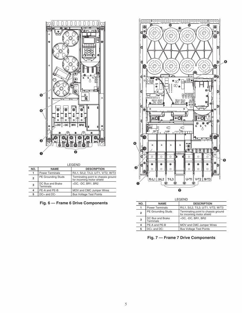
Components and Physical Data — The 19XRVchillers use the Allen-Bradley PF755 Frame 6 drive for the230-amp rated application (Carrier Part No. 19XVR0230...).See Fig. 6.
The Allen-Bradley PF755 Frame 7 drive is used for the335-amp and 445-amp rated application (Carrier Part No.19XVR0335... and 19XVR0445...). See Fig. 7.
See Fig. 8 for the dimensions of Frames 6 and 7 for 19XRVchillers.
The 23XRV chiller uses the Frame 7 drive for 335-amp and455-amp rated applications (Carrier Part No. 23XVR0335...and 23XVR0445...). Frame 6 is not used.
See Fig. 9 for the dimensions of Frame 7 for 23XRVchillers.
1 L1 L2 L3
O
I
2DC+ DC–
0V
0V
LOCKOUT/TAGOUT
MULTIMETER
DC BUS TEST TERMINALSLOCATED INSIDEACCESS DOOR
Fig. 3 — Check DC Bus TerminalsA19-1814
21P - 1 0248 - 3 0
21P - 19XRV Std Tier
Voltage Code1 – 480 vac, 60 Hz2 – 380 vac, 50 Hz3 – 380 vac, 60 Hz4 – 400 vac, 50 Hz5 – 400 vac, 60 Hz6 – 415 vac, 50 Hz7 – 415 vac, 60 Hz
Full Load Amp Rating(Maximum Continuous Amps)*0248 – 2480361 – 3610477 – 477
5
Enclosure4 – Unit Mount Type 1/IP23 Liquid Cooled5 – Unit Mount Type 1/IP23 Liquid Cooled/Air Filter
Input Device3 – 65 KAIC Capacity Breaker4 – 100 KAIC Capacity Breaker
Meter Option0 – No Meters2 – Digital Meter
a19-2380
Fig. 4 — Rockwell Automation Drive Assembly Catalog Number Nomenclature: 19XRV Units
* For Carrier applications, maximum continuous amp ratingsare 230, 335, and 445.
21PB - 1 0248 - 3 0
21PB - 23XRV Std Tier
Voltage Code1 – 480 vac, 60 Hz2 – 380 vac, 50 Hz3 – 380 vac, 60 Hz4 – 400 vac, 50 Hz6 – 415 vac, 50 Hz7 – 415 vac, 60 Hz
Full Load Amp Rating(Maximum Continuous Amps)*0248 – 2480361 – 3610477 – 477
4
Enclosure1 – Unit Mount Type 1/IP23 Air Cooled/Filter4 – Unit Mount Type 1/IP23 Liquid Cooled
Input Device3 – 65 KAIC Capacity Breaker4 – 100 KAIC Capacity Breaker
Meter Option0 – No Meters2 – Digital Meter
a19-2381
0
Control Power0 – Standard1 – High
0
CE (Conformité Européenne)0 – No1 – Yes
Fig. 5 — Rockwell Automation Drive Assembly Catalog Number Nomenclature: 23XRV Units
* For Carrier applications, maximum continuous amp ratingsare 230, 335, and 445.
5
LEGEND
Fig. 6 — Frame 6 Drive Components
NO. NAME DESCRIPTION1 Power Terminals R/L1, S/L2, T/L3, U/T1, V/T2, W/T3
2 PE Grounding Studs Terminating point to chassis groundfor incoming motor shield
3 DC Bus and Brake Terminals
+DC, -DC, BR1, BR2
4 PE-A and PE-B MOV and CMC Jumper Wires5 DC+ and DC- Bus Voltage Test Points
A19-1832
LEGEND
Fig. 7 — Frame 7 Drive Components
NO. NAME DESCRIPTION1 Power Terminals R/L1, S/L2, T/L3, U/T1, V/T2, W/T3
2 PE Grounding Studs Terminating point to chassis ground for incoming motor shield
3 DC Bus and Brake Terminals
+DC, -DC, BR1, BR2
4 PE-A and PE-B MOV and CMC Jumper Wires5 DC+ and DC- Bus Voltage Test Points
A19-1833

6
CL
50.0
0 R
EF
54.0
0
36.00 REF
40.00
FRONT VIEW
CL
30.0
0
22.00
a19-2379
SIDE VIEW
Fig. 8 — 19XRV Enclosure Dimensions — Frames 6 and 7
NOTE: Dimensions shown in inches.
Fig. 9 — 23XRV Enclosure Dimensions — Frame 7
a19-2011
NOTE: Dimensions shown in inches.
7
START-UP
Alternate Wire Lugs — If the incoming power wiresize does not fit the standard lug, alternate lugs may be used.See Table 1. Note that lugs rated for a higher current than thecircuit breaker may be used.
Table 1 — Wire Lugs
Verify Installation — Record the following jobinformation:
1. Job Name2. Job Number3. City4. State5. Zip Code
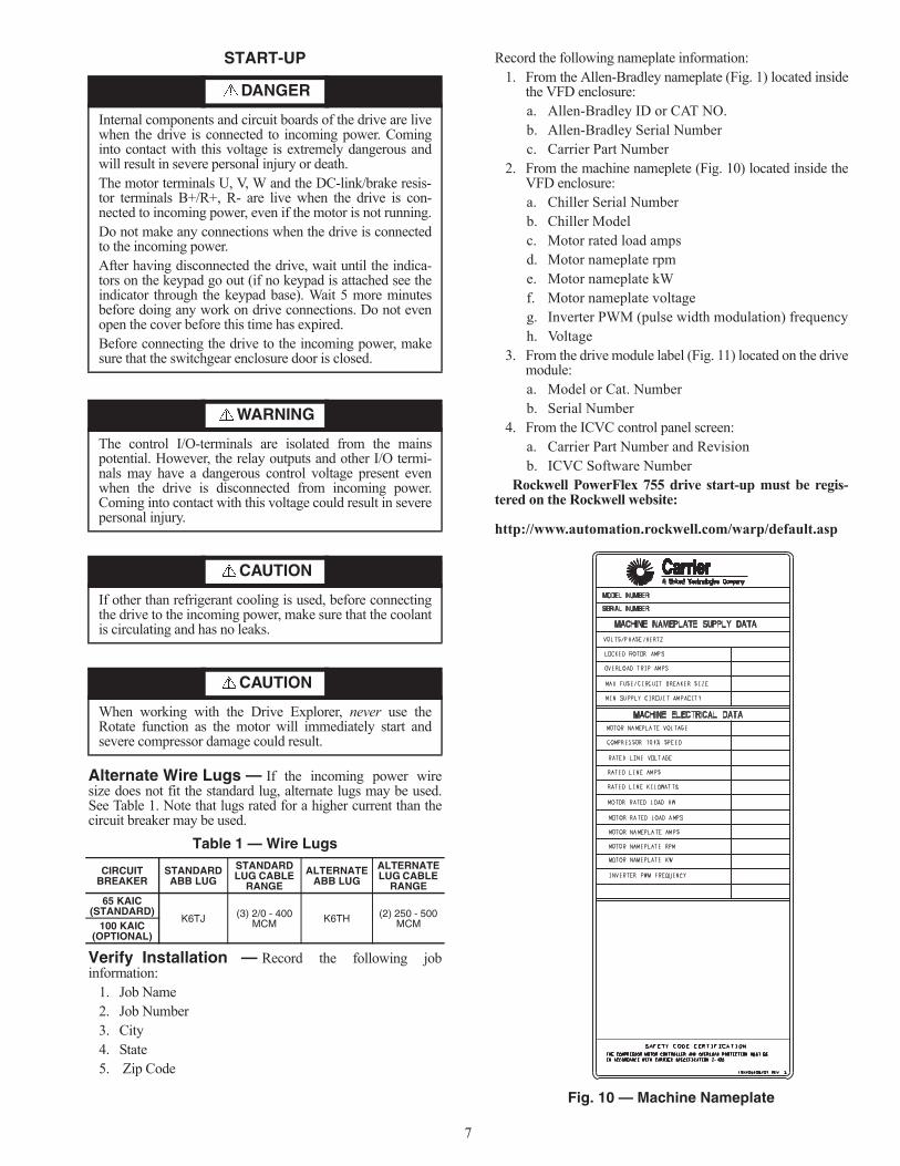
Record the following nameplate information:1. From the Allen-Bradley nameplate (Fig. 1) located inside
the VFD enclosure:a. Allen-Bradley ID or CAT NO.b. Allen-Bradley Serial Numberc. Carrier Part Number
2. From the machine nameplete (Fig. 10) located inside theVFD enclosure:a. Chiller Serial Numberb. Chiller Modelc. Motor rated load ampsd. Motor nameplate rpme. Motor nameplate kWf. Motor nameplate voltageg. Inverter PWM (pulse width modulation) frequencyh. Voltage
3. From the drive module label (Fig. 11) located on the drivemodule:a. Model or Cat. Numberb. Serial Number
4. From the ICVC control panel screen: a. Carrier Part Number and Revisionb. ICVC Software Number
Rockwell PowerFlex 755 drive start-up must be regis-tered on the Rockwell website:
http://www.automation.rockwell.com/warp/default.asp
DANGER
Internal components and circuit boards of the drive are livewhen the drive is connected to incoming power. Cominginto contact with this voltage is extremely dangerous andwill result in severe personal injury or death.The motor terminals U, V, W and the DC-link/brake resis-tor terminals B+/R+, R- are live when the drive is con-nected to incoming power, even if the motor is not running.Do not make any connections when the drive is connectedto the incoming power.After having disconnected the drive, wait until the indica-tors on the keypad go out (if no keypad is attached see theindicator through the keypad base). Wait 5 more minutesbefore doing any work on drive connections. Do not evenopen the cover before this time has expired.Before connecting the drive to the incoming power, makesure that the switchgear enclosure door is closed.
WARNING
The control I/O-terminals are isolated from the mainspotential. However, the relay outputs and other I/O termi-nals may have a dangerous control voltage present evenwhen the drive is disconnected from incoming power.Coming into contact with this voltage could result in severepersonal injury.
CAUTION
If other than refrigerant cooling is used, before connectingthe drive to the incoming power, make sure that the coolantis circulating and has no leaks.
CAUTION
When working with the Drive Explorer, never use theRotate function as the motor will immediately start andsevere compressor damage could result.
CIRCUIT BREAKER
STANDARDABB LUG
STANDARD LUG CABLE
RANGE
ALTERNATE ABB LUG
ALTERNATE LUG CABLE
RANGE65 KAIC
(STANDARD)K6TJ (3) 2/0 - 400
MCM K6TH (2) 250 - 500 MCM100 KAIC
(OPTIONAL)
Fig. 10 — Machine Nameplate
a19-1846

8
Configure the VFD — All configurations required bythe VFD are supplied by the ICVC through the VFD Gateway.19XRV, 23XRV Std Tier VFD can operate with PIC III ICVCand above. Any configuration changes necessary and possibleare made on the ICVC screens. A complete set of configura-tions is transmitted to the VFD each time the controls are pow-ered up.
Table 2 lists parameters displayed on the 19XRV, 23XRVPIC ICVC screen. Parameters in italics are to be entered orconfirmed at start-up. Parameters in bold are to be changedonly after consulting with Carrier service engineering.
Table 2 — VFD Configurations
* Parameters marked with an * are not downloadable to the VFD but are usedin other calculations and algorithms in the ICVC.† Parameters marked with a † may not be available with PIC-IV ICVC.NOTES:
1. Parameters in italics are to be entered or confirmed at start-up.2. Parameters in bold are to be changed only after consultation with ser-
vice engineering.
Commissioning the Unit — The commission proce-dure is as follows:
1. If the chiller has been stored outdoors, allow at least 24hours room temperature stabilization prior to commis-sioning. Ensure any condensation that occurs as a resultof the ambient temperature is allowed to evaporate.
2. Enter parameters in the VFD_CONF screen.3. Install surge suppression devices if required.4. Review the power wiring and grounding to ensure that it
has been properly connected.5. Visually examine the inside of the drive enclosure to:
a. Look for signs of corrosion or moisture residue. b. Remove any dirt or debris. c. Make sure all vents are clear.
6. Apply power to the drive and take thermal measurementsof the capacitor bank and power connections. Do thisagain before start-up.
7. Measure and record the incoming line voltage. Line-to-line voltages should be balanced within 3% as calculatedby Rockwell’s procedure below:
Measure voltages phase-to-phase and phase-to-ground.
Vmax = Maximum measured phase-to-phase voltage (A to B, B to C, C to A)
Vmin = Minimum measured phase-to-phase voltage Imbalance Calculation Formula
8. Take a final thermal measurement of the capacitor bankand power after finalizing the installation to ensure allconnections are good.
9. If a ground fault occurs, then do the following:a. Check for a ground in the motor or motor wiring.b. Check for damage to wiring insulation and that
wiring is dry.c. Verify the motor wiring is separated from ground
and there is no connection between phases.d. Check for failed IGBTs.
10. If an overcurrent fault occurs, then do the following:a. Check for excessive load and verify load limit set-
tings on the ICVC.b. Check motor and wiring insulation.c. Check parameter settings on VFD_CONF screen
in the ICVC.
Check Internal Jumpers — On the Main VFD Con-trol board there are two jumpers labeled J1 HARDWARE EN-ABLE and J2 SAFETY ENABLE. J1 should be removed andJ2 should be in place. See Fig. 12.
Two jumper wires connect a particular terminal to chassisground. The MOV and AC EMI jumper should be connectedto the PE-A terminal. The COMMON MODE CAPACITORSto GROUND jumper should be connected to a standoff ratherthan the PE-B terminal.
Use the recommended tools as follows when connectingjumper wires in Frame 6 and in Frame 7:• Recommended torque (screws and nuts) = 1.36 N·m
(120.0 lb·in.) • Recommended hex socket = 7 mm• Recommended screwdriver = T20 star type
PARAMETER DEFAULT VALUE
MOTOR NAMEPLATE VOLTAGE 460COMPRESSOR 100% SPEED LINE FREQ=60 HZ? (NO=50) YESRATED LINE VOLTAGE* † 460RATED LINE AMPS* † 200RATED LINE KILOWATTS* † 100MOTOR RATED LOAD KW* 100MOTOR RATED LOAD AMPS* 200MOTOR NAMEPLATE AMPS 100MOTOR NAMEPLATE RPM 3456MOTOR NAMEPLATE KW 100INVERTER PWM FREQUENCY (0 = 4 KHZ,1 = 2 KHZ) 1
SKIP FREQUENCY 1 (HZ) 20.0SKIP FREQUENCY 2 (HZ) 20.0SKIP FREQUENCY 3 (HZ) 20.0SKIP FREQUENCY BAND LINE (HZ) 0.0VOLTAGE % IMBALANCE 10LINE VOLT IMBALANCE TIME (SEC)† 10LINE CURRENT % IMBALANCE† 40LINE CURRENT IMBAL TIME (SEC)† 10MOTOR CURRENT % IMBALANCE 40MOTOR CURRENT IMBAL TIME 10INCREASE RAMP TIME (SEC) 30DECREASE RAMP TIME (SEC) 30SINGLE CYCLE DROPOUT (DSABLE/ENABLE) DSABLE
Fig. 11 — Drive Module Label
a19-1924
Vavg = (VAB + VBC + VCA)3
Imbalance % = (Vmax – Vmin) x 100Vavg

9
See Fig. 13 and Fig. 14 for the correct positions of thejumpers.
Fig. 12 — PF755 Main Control Board
TB1 I/O TERMINAL DESIGNATIONSFIXED I/O TERMINAL NAME DESCRIPTION
Di 0ac Digital Input 120V AC Connections for AC power supply.
Di C Digital Input Common Digital input common
Di 0dc Digital Input 24V DC Connections for DC power supply.
+24V +24 Volt Power Connections for drive supplied 24V power.
24VC 24 Volt Common
IMPORTANT: Wiring to pluggable terminal block connectorsshould be supported by wire ties or other means to help pre-vent unintentional disconnection.
Di 0ac
Di C
Di 0dc
+24V
24VC
a19-1921
LEGENDNO. NAME DESCRIPTION
1 HIM (HumanInterface Module)Connector
DPI Port 1 (HIM Cradle) connection.
2 Fan Connector Power supply for internal cooling fan (Frames 2 and 3).
3
BatteryReceptacle
User installed CR1220 lithium coin cell battery provides power to the Real Time Clock (Optional, notsupplied).
4 DPI Port 2 Cable connection for handheld and remote HIM options.
5Embedded Ethernet/IP Address Selectors
Rotary switches for setting lowest octet of Ethernet address (forces address to 192.168.1.xxx).
6 Embedded Ethernet/IP Connector
Network cable connection.
7
Jumper J2 SAFETY ENABLE
Safety enable jumper. Removed when safety option is installed. For additional information, refer to the Check Internal Jumpers section on page 8.
8
Jumper J1 HARD-WARE ENABLE
Hardware enable jumper. Removed when a hardware enable configura-tion is utilized. For additional infor-mation, refer to the Check Internal Jumpers section on page 8.
9 TB1 I/O terminal block.
CONNECTED DISCONNECTED
COMMON MODE
MOV
A19-2325
Fig. 13 — Jumper Wire Locations — Frame 6
CONNECTED DISCONNECTED
COMMON MODE
MOV
A19-2326
Fig. 14 — Jumper Wire Locations — Frame 7

10
SERVICE
Troubleshooting the Drive — The drive can displaytwo kinds of error codes on the ICVC called Alert and Alarmcodes. These codes signal a problem detected during self tun-ing or drive operation. Note the following differences betweenCarrier and Allen-Bradley terminology:• A warning message on the ICVC is an ALERT.• The same warning viewed with Rockwell Drive Explorer
is a VFD ALARM. • A failure resulting in a shutdown is seen as an ALARM
on the ICVC and as a VFD FAULT when viewed withDrive Explorer.CONDITION CODESICVC ALERT = VFD ALARMICVC ALARM = VFD FAULTSee Tables 3-4 and Fig. 15.
ICVC ALERT CODES — An alert condition is indicated bya message at the top of the ICVC default screen. In addition, anexclamation point (!) will appear next to any affected point onan ICVC display screen. The drive will continue to operateduring the alert condition. Investigate the cause of the alert toensure it does not lead to a fault condition. The alert code willautomatically be cleared from the ICVC when the conditioncausing the alert no longer exists. See the 19XRV or 23XRVStart-Up, Operation and Maintenance Instructions for ICVCalert codes.
ICVC ALARM CODES — An alarm condition is also indi-cated by a message at the top of the ICVC default screen. If analarm occurs, the drive coasts to stop. The STS (status) light onthe drive will turn from Green to Red or Yellow (see Table 3).The detected fault message is maintained on the display until itis cleared by pressing the RESET softkey. See the 19XRV or23XRV Start-Up, Operation and Maintenance Instructions forICVC alarm codes.TEST EQUIPMENT NEEDED TO TROUBLESHOOT —An isolated multimeter adequately rated for the DC bus volt-age will be needed to measure DC bus voltage and to makeresistance checks. Note that dedicated troubleshooting testpoints are not provided.
Table 3 — Drive Status Indicator Descriptions
NOTES:1. A Type 1 alarm indicates that a condition exists. Type 1 alarms
are user configurable.
2. A Type 2 alarm indicates that a configuration error exists andthe drive cannot be started. Type 2 alarms are not configurable.
WARNING
DC bus capacitors retain hazardous voltages after inputpower has been disconnected. After disconnecting inputpower, wait five (5) minutes for the DC bus capacitors todischarge and then check the voltage with a voltmeter toensure the DC bus capacitors are discharged before touch-ing any internal components. Failure to observe this pre-caution could result in severe bodily injury or loss of life.
2
8
5
7 9
1 3
4 6
Allen-Bradley
Fig. 15 — Drive Status Indicator
A19-1815
NAME COLOR STATE DESCRIPTION
STS (Status)
Green Flashing Drive ready but not running, and no faults are present.Steady Drive running, no faults are present.
Yellow Flashing Drive is not running. A type 2 (non-configurable) alarm condition exists and the drive cannot be started.
Steady Drive is not running, a type 1 alarm condition exists. The drive can be started.Red Flashing A major fault has occurred. Drive cannot be started until fault condition is
cleared.Steady A non-resettable fault has occurred.
Red/Yellow Flashing Alternately A minor fault has occurred. When running, the drive continues to run. System is brought to a stop under system control. Fault must be cleared to continue. Use parameter 950 [Minor Flt Config] to enable. If not enabled, acts like a major fault.
Green/Red Flashing Alternately Drive is flash updating.
ENET
None (Unlit) Off Adapter and/or network is not powered, adapter is not properly connected to the network, or adapter needs an IP address.
Red Flashing An Ethernet/IP connection has timed out.Steady Adapter failed the duplicate IP address detection test.
Red/Green Flashing Alternately Adapter is performing a self-test.Green Flashing Adapter is properly connected but is not communicating with any devices on
the network.Steady Adapter is properly connected and communicating on the network.
LINKNone (Unlit) Off Adapter is not powered or is not transmitting on the network.Green Flashing Adapter is properly connected and transmitting data packets on the network.
Steady Adapter is properly connected but is not transmitting on the network.

11
VERIFYING THAT DC BUS CAPACITORS ARE DIS-CHARGED — The drive’s DC bus capacitors retain hazard-ous voltages after input power has been disconnected. Performthe following steps before touching any internal components:
1. Turn off and lock out input power. Wait five minutes.2. Verify that there is no voltage at the drive’s input power
terminals.3. Measure the DC bus potential with a voltmeter while
standing on a non-conductive surface and wearing insu-lated gloves (1000 V). Measure the DC bus potential. SeeFig. 6 for the 248-amp drive and Fig. 7 for the 361 and477-amp drives. The voltage between DC+ and DC-, andfrom each DC terminal to the chassis must be zero beforeproceeding.
4. Once the drive has been serviced, reapply input power.HIGH TEMPERATURE ALARMS — Coolant flowthrough the cold plate is controlled by an orifice in the refriger-ant line leaving the cold plate. The orifice looks like one of theO-ring face seal connectors and in fact is used as one of theconnections on the coolant tubing. If the orifice is present andcondenser liquid flow is present, the liquid will flash to coolertemperature at the orifice. This temperature difference is greatenough to be easily felt.MAIN CONTROL BOARD (MCB) COMPONENTS —Figure 16 shows the drive module with the cover removed. Toaccess the control boards, loosen the screw on the face of thekeypad mount and swing the keypad mount upward.
The components on the main control board (MCB) areshown in Fig. 17. Note the location of the terminals labeledMCB I/O. The high-pressure switch is wired to these terminalsas shown in Fig. 18. In the event of a high condenser pressurealarm, the connections at these terminals should be checkedand tightened if necessary.
Typical wiring schematics are shown in Appendix A.
SWING UP KEY PADMOUNT TO ACCESSCONTROL BOARDS
Fig. 16 — Drive Module with Cover Removed
a19-1843
DPI PORT 02 (COMPUTER PORT)
DIGITAL INPUT TERMINAL BLOCKS (SLOTS 04 & 05)
ETHERNET/IP ADDRESS SWITCHES
DIGITAL OUTPUT TERMINAL BLOCKS (SLOTS 04 & 05)
EMBEDDED ETHERNET/IP PORT
MCB I/O TERMINALS (AUX FAULT / HIGH PRESSURE FAULT / ENABLE INPUT)
Fig. 17 — MCB (Main Control Board) Components
a19-1844
*Located outside of starter; connected by field wiring.
Fig. 18 — High Pressure Switch Wiring
a19-1925

12
Table 4 — Powerflex 755 Fault Code Descriptions and Corrective Actions
VFD FAULT CODE
ON VFD HIST
SCREEN
ICVC FAULT STATE
FAULT TYPE DESCRIPTION CORRECTIVE ACTION
NONE 206 Processor memory fault Consult VFD manual to resolve generic fault.0 No Entry
2 207 Auxiliary Input Input is open.
Check Compressor Discharge High Pressure switch wiring and accuracy.Check for high condenser water temperatures, low water flow, fouled tubes.Check for division plate/gasket bypass. Check for noncondensables in refrigerant.
3 210 Power Loss Line voltage dropout Temporary loss of voltage. Disable Single Cycle Dropout in VFD_CONF sceen.
4 215 Undervoltage Low DC bus voltageVerify phase-to-phase and phase-to-ground linevoltage. VFD Circuit Board malfunction.Contact Carrier Service.
5 166 Overvoltage High DC bus voltageVerify phase to phase and phase to ground linevoltage. Monitor AC line for high transient volt-age conditions.
7 217 Motor Overload An internal electronic overload trip has occurred.
Any phase current > 106% RLA. Can result fromsignificant load side current imbalance whenrunning at full load.Check entering condenser water temperatureand water flow rate.Check Motor Rated Load Amps in VFD_CONFscreen.
8 219 Heat Sink Over-temp
Heat sink temperature has exceeded maximum operating temperature.
Check that VFD refrigerant isolation valves are open.Check VFD refrigerant cooling orifice and refrig-erant strainer.Check for proper VFD cooling fan operation and air flow blockage.
9 219 Transistor Over-temp
The output transistors have exceeded maximum operating temperature.
Check that VFD refrigerant isolation valves are open.Check VFD refrigerant cooling orifice and refrig-erant strainer.Check for proper VFD cooling fan operation and air flow blockage.
12 286 HW Overcurrent The drive output current has exceeded hardware current limit.
Check for high entering water temperature or low condenser water flow. Check current settings in VFD_CONF screen.
13 220 Ground Fault A current path to earth ground greater than 25% of drive rating has occurred.
Check the motor, motor terminals, and external wiring to the drive output terminals for a grounded condition.
14 206 Ground Warning The ground current has exceeded the level set in P467. —
15 206 Load Loss If this fault appears, there may be a problem with software configuration.
To reset the processor, cycle power to chiller, check ICVC VFD_CONF settings and save set-tings when exiting VFD_CONF screen. Check VFD parameters with Drive Explorer.
17 216The DC bus ripple has exceeded a preset level.
Line Voltage imbalanceCheck phase-to-phase and phase-to-ground dis-tribution bus voltage. Increase Line Voltage % Imbalance in VFD_CONF screen.
20 206 TorqPrv Spd Band See VFD Fault Code 15 See VFD Fault Code 15
21 225 Output PhaseLoss The current in one or more phases has been lost or remains below a preset level.
Check Motor Current % Imbalance in VFD_CONF screen.
24 204 Decel Inhibit The drive is not following a commanded decelera-tion because it is attempting to limit bus voltage.
Verify input voltage is within drive specifiedlimits.Verify system ground impedance follows proper grounding techniques.Disable bus regulation P186 and/or add dynamic brake resistor and/or extend deceleration time P537 and P538.
33 206 AuRsts Exhausted See VFD Fault Code 15 See VFD Fault Code 15
36 286 SW Overcurrent The drive output current has exceeded the 1 ms current rating.
Check for excess load, improper DC boost set-ting, DC brake volts set too high.

13
Table 4 — Powerflex 755 Fault Code Descriptions and Corrective Actions (cont)
VFD FAULT CODE
ON VFD HIST
SCREEN
ICVC FAULT STATE
FAULT TYPE DESCRIPTION CORRECTIVE ACTION
38
220
Phase U to Gnd
GROUND FAULT
Check wiring between drive and motor. Check motor for grounded phase. Check motor terminals.Replace drive.
39 Phase V to Gnd
40 Phase W to Gnd
41246
Phase UV ShortGROUND FAULT
Check wiring between drive and motor. Check motor terminals. Replace drive.
42 Phase VW Short43 Phase WU Short
44 206 Phase UNot
GROUND FAULT (no LF2 equivalent)Check wiring between drive and motor. Check motor terminals. Replace drive.
45 206 Phase VNot
46 206 Phase WNot
55 NONE Inverter Overtemp The temperature sensor on the main control board detected excessive heat.
Check that VFD refrigerant isolation valves are open. Check VFD refrigerant strainer.
61 206 Shear Pin 1 See VFD Fault Code 15 See VFD Fault Code 1562 206 Shear Pin 2 See VFD Fault Code 15 See VFD Fault Code 15
64 206 Drive Overload Drive is overloaded.Check for high entering water temperature or low condenser water flow. Check current settings in VFD_CONF screen.
65 206 OW TrqLvlTimeout See VFD Fault Code 15 See VFD Fault Code 1577 206 IR Volts Range See VFD Fault Code 15 See VFD Fault Code 15
78 206 FluxAmpsRef Rang See VFD Fault Code 15 See VFD Fault Code 15
79 206 Excessive Load Motor did not come up to speed in the allotted time.
Check that guide vanes are closed completely. Check for high entering water temperature or low condenser flow. Repeat Autotune
80 206 AutoTune Aborted See VFD Fault Code 15 See VFD Fault Code 15
87 206 IXo VoltageRange Ixo voltage calculated from motor nameplate data is too high.
Re-enter motor nameplate data in VFD_CONF screen.
91 206 Pri VelFdbk Loss See VFD Fault Code 15 See VFD Fault Code 1593 206 HW Enable Check See VFD Fault Code 15 See VFD Fault Code 1594 206 Alt VelFdbk Loss See VFD Fault Code 15 See VFD Fault Code 1595 206 Aux VelFdbk Loss See VFD Fault Code 15 See VFD Fault Code 1596 206 PositionFdbkLoss See VFD Fault Code 15 See VFD Fault Code 1597 206 Auto Tach Switch See VFD Fault Code 15 See VFD Fault Code 15
100 206 Parameter Chk-sum
The checksum read from the board does not match the checksum calculated.
Press ICVC reset. Check VFD_CONF parameters. Cycle power to the drive.
107 NONE Replaced MCB-PB The main control board was moved to a different power structure. Data set to default values.
Press ICVC reset. Check VFD_CONF parameters. Cycle power to the drive.
113 206 Tracking DataErr Internal data error Press ICVC reset. Cycle power to the drive.
124 206 App ID Changed Application firmware changed. Verify application version.141 206 Autn Enc Angle P78 [Encdrlss AngComp] is out of range. See VFD Fault Code 15142 206 Autn Spd Rstrct See VFD Fault Code 15 See VFD Fault Code 15143 206 Autotune CurReg See VFD Fault Code 15 See VFD Fault Code 15144 206 Autotune Inertia See VFD Fault Code 15 See VFD Fault Code 15145 206 Autotune Travel See VFD Fault Code 15 See VFD Fault Code 15

14
Table 4 — Powerflex 755 Fault Code Descriptions and Corrective Actions (cont)
Checking Power Modules and Motor Inputwith Input Power Off — Use the following procedureto check the drive’s power module circuitry with power off:
1. Turn off and lock out input power. Wait five minutes.2. Verify there is no voltage at the drive’s input power termi-
nals.3. Using a voltmeter, check the DC bus potential as de-
scribed in the section Verifying That Dc Bus CapacitorsAre Discharged on page 11 to ensure the DC bus capaci-tors are discharged.
4. Disconnect the motor from the drive.5. Check all AC line and DC bus fuses.6. Use a multimeter to check the input diodes and output
IGBTs if a fuse is open. See Table 5.7. Check motor impedance.8. Reconnect the motor to the drive.9. Reapply input power.
Table 5 — Diode Checks
NOTE: Digital meters require a special diode check functionbecause the current sourced by the meter during a normal resis-tance (Ohms) test is too low to accurately test a diode. Make surethe meter is set to the diode test function. Voltage readings may notbe exact as shown in above table, but look for consistency duringeach of the 4 tests. When performing a test that should return infinity(OL) as shown in above table, you may see a value slowly climbingtoward infinity. This is a result of the meter charging a capacitor andis normal.
VFD FAULT CODE
ON VFD HIST
SCREEN
ICVC FAULT STATE
FAULT TYPE DESCRIPTION CORRECTIVE ACTION
168 206 HeatSinkUnder-Tmp
Heatsink temperature sensor is reporting a value below –18.7 C (–1.66 F) or the sensor feedback circuit is open.
Check heat sink temperature sensor. Check heat sink temperature.
210 206 HW En Jumper Out See VFD Fault Code 15 See VFD Fault Code 15
211 206 Safety Brd Fault See VFD Fault Code 15 See VFD Fault Code 15213 206 Safety Jumper In See VFD Fault Code 15 See VFD Fault Code 15291 206 HSFan Lifwe See VFD Fault Code 15 See VFD Fault Code 15292 206 InFan Life See VFD Fault Code 15 See VFD Fault Code 15293 206 MtrBrg Life See VFD Fault Code 15 See VFD Fault Code 15294 206 MtrBrg Lube See VFD Fault Code 15 See VFD Fault Code 15295 206 MachBrg life See VFD Fault Code 15 See VFD Fault Code 15296 206 MachBrg Lube See VFD Fault Code 15 See VFD Fault Code 15315 206 Excess Psn Error See VFD Fault Code 15 See VFD Fault Code 15
WARNING
DC bus capacitors retain hazardous voltages after inputpower has been disconnected. After disconnecting inputpower, wait five (5) minutes for the DC bus capacitors todischarge and then check the voltage with a voltmeter toensure the DC bus capacitors are discharged before touch-ing any internal components. Confirm that the DC bus hasdischarged before performing diode checks. Failure toobserve this precaution could result in severe bodily injuryor loss of life.
METER LEADMETER READING
(+) (-)
RDC+ 0.5 VDC- Infinite (OL)
SDC+ 0.5 VDC- Infinite (OL)
TDC+ 0.5 VDC- Infinite (OL)
UDC+ 0.5 VDC- infinite (OL)
VDC+ 0.5 VDC- Infinite (OL)
WDC+ 0.5 VDC- Infinite (OL)
DC+
R
Infinite (OL)
STUVW
DC-
R
0.5 V
STUVW

15
Servicing the Drive
1. Using recommended screwdriver (6.4 mm [0.25 in.] flator T20 star), open access door. See Fig. 19.
2. Check to be sure that the voltage between DC+ and DC-and from each DC terminal to the chassis is zero beforeproceeding. See Fig. 20.
3. Remove the enclosure. See Fig. 21.REMOVING THE DRIVE — The dimensions and weightsspecified must be taken into consideration when removing thedrive. All lifting equipment and lifting components (hooks,bolts, lifts, slings, chains, etc.) must be properly sized and ratedto safely lift and hold the weight of the drive while removing it.For 19XRV chillers, see Fig. 22. For 23XRV chillers, seeFig. 23. The drive weights are as follows:• Drive weight for Frame 6: 85 lb.• Drive weight for Frame 7: 160 - 249 lb.
When replacing the drive, reverse the procedures and tight-en to the torques for Frames 6 and 7 power terminal block list-ed in Table 6.
Table 6 — Frames 6 and 7 Power Terminal Block
RIGGING THE ENCLOSURE — Where overhead roomand/or clearance in front of the drive enclosure is insufficient toallow the drive to be safely removed from the enclosure, theentire enclosure may have to be removed from the chiller.
The dimensions and weights specified must be taken intoconsideration when removing the enclosure. For 19XRV chill-ers, the total weight for Frames 6 and 7, including drive weightand enclosure, is 720 lb. The 23XRV chiller enclosure, includ-ing all components, weighs 975 lb. All lifting equipment andlifting components (hooks, bolts, lifts, slings, chains, etc.) mustbe properly sized and rated to safely lift and hold the weight ofthe enclosure and drive while removing. See Fig. 24 andFig. 25.
WARNING
To guard against possible personal injury and/or equipmentdamage:
1. Inspect all lifting hardware for proper attachment be-fore lifting drive.
2. Do not allow any part of the drive or lifting mecha-nism to make contact with electrically charged con-ductors or components.
3. Do not subject the drive to high rates of accelerationor deceleration while transporting to the mounting lo-cation or when lifting.
Do not allow personnel or their limbs directly underneaththe drive when it is being lifted and mounted.
WARNING
DC bus capacitors retain hazardous voltages after inputpower has been disconnected. After disconnecting inputpower, wait five (5) minutes for the DC bus capacitors todischarge and then check the voltage with a voltmeter toensure the DC bus capacitors are discharged before touch-ing any internal components. Failure to observe this pre-caution could result in severe bodily injury or loss of life.
Fig. 19 — Open Access Door
A19-1831
FRAME MAXIMUM LUG WIDTH
RECOMMENDED TORQUE
TERMINAL BOLT SIZE
6 34.6 mm (1.36 in.) 11.3 N·m (100 in.-lb) M8 x 1.257 43.5 mm (1.71 in.) 11.3 N·m (100 in.-lb) M8 x 1.25
1 L1 L2 L3
O
I
2DC+ DC–
0V
0V
LOCKOUT/TAGOUT
MULTIMETER
DC BUS TEST TERMINALSLOCATED INSIDEACCESS DOOR
Fig. 20 — Check DC Bus Terminals
A19-1814
90°
SLIDEENCLOSUREFORWARDLOOSEN
ENCLOSUREFASTENERS
Fig. 21 — Removing Enclosure
A19-1816

16
DRIVE RIGGING ACCESSDRIVE WIDTH + 4 IN.
FRONT VIEW
SIDE VIEW
DRIVE RIGGINGACCESS
2 IN.2 IN.
DRIVE POSITIONED FORVERTICAL LIFT
SUPPORT FROMBELOW
DRIVE EXTENDSBEHIND MAINENCLOSURE
Fig. 22 — 19XRV Enclosure Accessfor Removing Drive
A19-1818
a19-1817
DRIVE EXTENDS BEHINDMAIN ENCLOSURE
SUPPORT FROMBELOW
DRIVE POSITIONED FORVERTICAL LIFT
ENCLOSURE TOPIS REMOVABLEFRONT CORNER OF
DRIVE COMPARTMENTIS REMOVABLE
SIDE VIEW
Fig. 23 — 23XRV Enclosure Access for Removing Drive
A19-2012
>1/2 A
A
<45°
Fig. 24 — Rigging the Enclosure, Frame 6
A19-1837
>1/2 A
A
<45°
Fig. 25 — Rigging the Enclosure, Frame 7
A19-1838

17
REPLACING THE GATEWAY (A-B20-750-20COMMOPTION CARD) — Follow these steps for removing and re-placing the existing gateway:
1. Disconnect power to the drive. Before removing the en-closure, open the access door on the front of the drive. See Fig. 19.
2. Check to be sure that the voltage between DC+ and DC-and from each DC terminal to the chassis is zero beforeproceeding. See Fig. 20.
3. Remove the enclosure. See Fig. 21.4. Remove the 2 screws securing the mounting plate and re-
move the mounting plate and COMM card. See Fig. 26.5. Mount the new COMM card and mounting plate and at-
tach with the 2 screws removed in Step 4. See Fig. 27.6. Use the shorter ribbon cable to connect the plug on the
COMM card to the connector on the mounting plate. SeeFig. 26.
7. Install the enclosure. See Fig. 21.
CHILL PLATE FAN AND INTERNAL FAN REPLACE-MENT — Follow these steps to replace the chill plate fan andinternal fan in Frames 6 and 7.Frame 6 (chill plate fan kit Z1P-FAN-A6-A):
1. Disconnect power to the drive. Before removing the en-closure, open the access door on the front of the drive. See Fig. 19.
2. Check to be sure that the voltage between DC+ and DC-and from each DC terminal to the chassis is zero beforeproceeding. See Fig. 20.
3. Remove the enclosure. See Fig. 21.4. Remove and replace the chill plate fan. See Fig. 28.5. Remove and replace the internal fan. See Fig. 29.6. Install the enclosure. See Fig. 21.
0.45-0.67 N-m (4.0-6.0 lb.-in.)
3 PLACES
MOUNTING PLATE
GATEWAY
RIBBON CABLE
Fig. 26 — COMM Card
A19-1819
MOUNTING PLATE
GATEWAY
Fig. 27 — Mount COMM Card Plate to Drive
A19-1820
T20
2.6 N•m (23 lb•in.)
CHILL PLATEFAN POWERCONNECTION
CHILL PLATE FAN
Fig. 28 — Chill Plate Fan, Frame 6
A19-1839

18
Frame 7 (chill plate fan kit Z1P-FAN-A7-A):1. Disconnect power to the drive. Before removing the en-
closure, open the access door on the front of the drive. See Fig. 19.
2. Check to be sure that the voltage between DC+ and DC-and from each DC terminal to the chassis is zero beforeproceeding. See Fig. 20.
3. Remove the enclosure. See Fig. 21.
4. Remove and replace the chill plate and internal fans. SeeFig. 30.
5. Install the enclosure. See Fig. 21.
Part Identification and Location — See Fig. 31-34for parts descriptions and locations.
T20
2.6 N•m(23 lb•in.)
T202.6 N•m(23 lb•in.)
INTERNAL FAN
Fig. 29 — Internal Fan, Frame 6
A19-1840X 2
T20
5.20 N•m(46 lb•in.)
T15
2.6 N•m (23 lb•in.)
T15
INTERNAL FANS
CHILL PLATE FANS2.6 N•m (23 lb•in.)
Fig. 30 — Chill Plate and Internal Fans, Removal and Replacement, Frame 7
A19-1841
3PKTK/FNQ-R
30A
1 1 1
2 2 2
12
34
56
78
910111213 1415161718 19202122232425
TB4
262728293031 32333435363738394041424344 4546474849505152 5354555657 5859606162636465666768697071 7273747576777879808
76
54
32
19141211 10 13
CR1
87
65
43
219
141211 10 13
CR2
87
65
43
219
141211 10 13
CR3
87
65
43
219
141211 10 13
CR4
87
65
43
219
141211 10 13
CR5
87
65
43
219
141211 10 13
CR6
EA1
CB1
CABLE ACCESS CUTOUT
SECONDARY SIDE
PT1
CB
12
34
56
78
9101112131415 16171819202122 2324 25
TB4
262728293031 32333435 363738 39404142 434445 4647484950515253 545556 57585960616263 6465666768697071727374 7576 7778 79808
76
54
32
19141211 10 13 CR1
87
65
43
219
141211 10 13 CR2
87
65
43
219
141211 10 13 CR3
87
65
43
219
141211 10 13 CR4
87
65
43
219
141211 10 13 CR5
87
65
43
219
141211 10 13 CR6
PT1SECONDARYSIDE TOWARD DOOR
CB2
FRONT VIEWDOOR REMOVED
LEFT SIDEWALLVIEW FROM INSIDE
1
80
LINE-PE
6
53
2
4
1
TB1,TB2,FU1-FU3
TB4
CR1
CR6
DIST.SIDE
TB1 TB2FU2
FU1 FU3
Fig. 31 — 19XRV Assembly Parts
LEGEND1 — Power Module2 — Input Circuit Breaker3 — 15 Amp Control Circuit Breaker4 — Control Transformer5 — Control Fuses6 — Control Relays (CR1 - CR6)
a19-1847

19
FRONT VIEW – DOORS REMOVED RIGHT SIDEWALL INSIDE VIEW
21 3
4
5
7
8
6
Fig. 32 — 23XRV Assembly Parts
LEGEND1 — Input Circuit Breaker2 — Power Module3 — Control Relays (CR1 - CR6)4 — Control Fuses5 — 120V Control Transformer6 — 120V Vaporizer Heater Transformer7 — 15 Amp Control Circuit Breaker8 — Cooling Fan
a23-1653

20
LEGEND1 — PF750 Series, Precharge Kit2 — PF750 Series, Gate Interface3 — PF750 Series, Power Interface4 — PowerFlex 750 Series, Flange Gasket5 — PF755 Main Control Board6 — PF750 Series, Backplane Interface7 — PF750 Series, Type 4X/12 Chill Plate (Heatsink) Fan Kit8 — Chill Plate Fan
NOTE: When replacing the Main Control Board (Item No. 5) the jumpermarked “J1 HARDWARE ENABLE” must be removed and the jumpermarked “J2 SAFETY ENABLE” must be left in place.
a19-1848
Fig. 33 — Frame 6 Parts
Fig. 34 — Frame 7 Parts
LEGEND
NOTE: When replacing the Main Control Board (Item No. 10) thejumper marked “J1 HARDWARE ENABLE” must be removed andthe jumper marked “J2 SAFETY ENABLE” must be left in place.
1 — Slot for Gateway (Gateway Not Shown)2 — PF750 Series, Backplane Interface3 — PF750 Series, Type 4X/12 Heatsink Fan Kit4 — PF750 Series, Power Interface5 — PF750 Series, Bus Cap Assembly6 — PF750 Series, Power Interface Cable7 — PF750 Series, Current Transducer Kit8 — PF750 Series, Precharge Kit9 — Slot for 24V I/O Module (24V I/O Module Not Shown)
10 — PF755 Main Control Board
a19-1849

21
APPENDIX A — WIRING SCHEMATICS19XRV CHILLER CONTROL SCHEMATIC
a19-2378
LE
GE
ND
CB
—C
ircui
t Bre
aker
CC
M—
Chi
ller
Con
trol
Mod
ule
HG
BP
—H
ot G
as B
ypas
sIC
VC
—In
tern
atio
nal C
hille
r V
isua
l Con
trol
ler
UP
C—
Uni
vers
al P
roto
col C
ontr
olle
r
Den
otes
Con
trol
Pan
el T
erm
inal
Den
otes
Oil
Pum
p T
erm
inal
Den
otes
Pow
er P
anel
Ter
min
al
**
Den
otes
Mot
or S
tart
er P
anel
Con
n
Den
otes
Com
pone
nt T
erm
inal
Wire
Spl
ice
Den
otes
Con
duct
or M
ale/
Fem
ale
Con
nect
or
Opt
ion
Wiri
ng

22
APPENDIX A — WIRING SCHEMATICS (cont)23XRV CHILLER CONTROL SCHEMATIC
a23-1731
NO
TE
S:
1.Li
quid
flo
w c
ircui
t: to
ins
tall
optio
nal
flow
dev
ice,
wire
as
show
n (N
.O.)
and
rep
lace
jum
per
with
a 4
.3k
resi
stor
.2.
For
TP
com
pres
sor,
the
cond
ense
r flo
w s
witc
h m
ust b
e in
stal
led
in s
erie
s w
ith th
e co
oler
flow
sw
itch.
Do
not c
onne
ct c
onde
nser
flow
sw
itch
to J
3 (L
ower
) 23
and
24.
3.F
or T
P c
ompr
esso
r, re
mov
e 4.
3k r
esis
tor
betw
een
J3 (
Low
er)
20 a
nd 2
1.

23
APPENDIX A — WIRING SCHEMATICS (cont)ROCKWELL POWERFLEX 755 WIRING SCHEMATIC (Typical)
19XRV (Typical)
a19-2327
SEE METER OPTIONDETAIL
See Legend on page 24.

24
APPENDIX A — WIRING SCHEMATICS (cont)ROCKWELL POWERFLEX 755 WIRING SCHEMATIC (Typical) (cont)
19XRV (Typical) (cont)
a19-2331LEGEND
CAP — CapacitorCB — Circuit BreakerCOM — CommonCOMM — CommunicationCOND — CondenserCR — Control RelayDPI/SI — Internal Communication Protocols
ConnectionsEA — Electrical AssemblyEMI — Electro-Magnetic InterferenceEVAP — EvaporatorFU — FuseGND — GroundJMPR — JumperM — MotorNC — Normally ClosedNO — Normally OpenPE — Potential Earth (Ground)POD — I/O Card Mounting Board SlotREM — RemoteRO — Relay OutputROC — Relay Output CommonSHLD — ShieldTB — Terminal Block

25
APPENDIX A — WIRING SCHEMATICS (cont)ROCKWELL POWERFLEX 755 WIRING SCHEMATIC (Typical) (cont)
23XRV (Typical)
a19-2328
See Legend on page 26.

26
APPENDIX A — WIRING SCHEMATICS (cont)ROCKWELL POWERFLEX 755 WIRING SCHEMATIC (Typical) (cont)
23XRV Typical (cont)
a19-2329
LEGENDCAP — CapacitorCB — Circuit BreakerCOM — CommonCOMM — CommunicationCOND — CondenserCR — Control RelayDPI/SI — Internal Communication Protocols
ConnectionsEA — Electrical AssemblyEMI — Electro-Magnetic InterferenceEVAP — EvaporatorFU — FuseGND — GroundJMPR — JumperM — MotorNC — Normally ClosedNO — Normally OpenPE — Potential Earth (Ground)POD — I/O Card Mounting Board SlotREM — RemoteRO — Relay OutputROC — Relay Output CommonSHLD — ShieldTB — Terminal Block
27
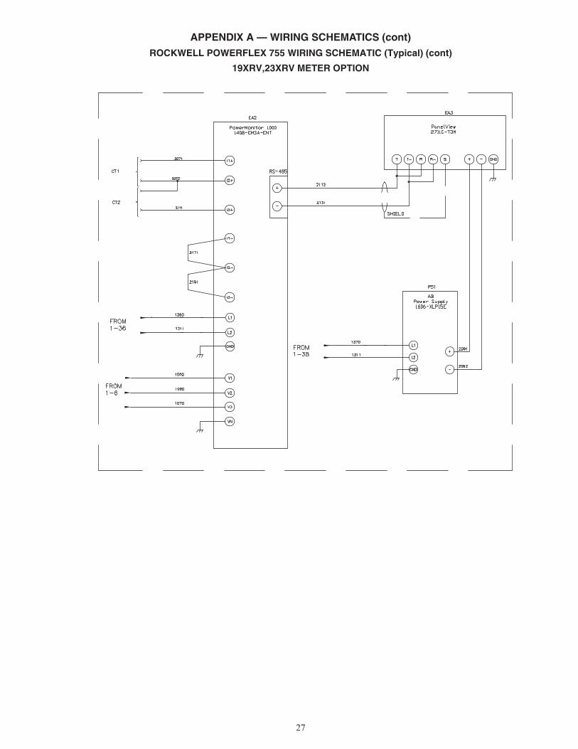
APPENDIX A — WIRING SCHEMATICS (cont)ROCKWELL POWERFLEX 755 WIRING SCHEMATIC (Typical) (cont)
19XRV,23XRV METER OPTION
a19-2330

Manufacturer reserves the right to discontinue, or change at any time, specifications or designs without notice and without incurring obligations.Catalog No. 04-53190033-01 Printed in U.S.A. Form 19/23-6SS Pg 28 8-15 Replaces: 19/23-4SS
© Carrier Corporation 2015