safety cautions - inverter & plcprogramming... · safety cautions (you must read these cautions...
TRANSCRIPT

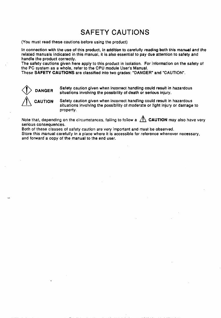
SAFETY CAUTIONS (You must read these cautions before using the product)
In connection with the use of this product, in addition to carefully reading both this manreal and the related manuals indicated in this manual, it is also essential to pay due attention to safety and handle the product correctly. The safety cautions given here apply to this product in isolation. For information on the safety of the PC system as a whole, refer to the CPU module User’s Mamral. These SAFETY CAUTIONS are classified into two grades: “DANGER” and “CAUTION”.
Safety caution given when incorrect handling could resutt in hazardous @ DANGER situations involving the possibility of death or serious injury. A CAUTION Safety caution given when incorrect handling could result in hazardous situations involving the possibility of moderate or light injury or damage to property.
Note that, depending on the circumstances, failing to follow a /A CAUTION may also have very serious consequences. Both of these classes of safety caution are very important and must be observed. Store this manual carefully in a place where it is accessible for reference whenever necessary, and forward a copy of the manual to the end user.

[System Design Precautions]
@ DANGER
Safety circuits shwM be installed external to the programmable controller to ensure that'the system as a whole will continue to operate safefy in the event of an external power supply malfunction or a pro,grammable controller failure. Erroneous outputs and operation could result in an accident. 1) The following circuitry should be installed outside the programmable
controller: Interlock circuitry for the emergency stop circuit protective circuit, and for reciprocal operations such as forwardreverse, etc., and interlock circuitry for upper/lower positioning limits, etc., to prevent machine damage.
processing is stopped and all outputs are switched OFF. This happens in the following cases:
When the power supply module's over-current or over-voltage protection
When an error (watchdog timer error, etc.) is detected at the PC CPU by
Some errors, such as input/output control errors, cannot be detected by the PC CPU, and there may be cases when all outputs are turned ON when such errors occur. In order to ensure that the machine operates safely in such cases, a failsafe circuit or mechanism should be provided outside the programmable controller. Refer to the CPU module user's manual for an example of such a failsafe circuit.
3) Outputs may become stuck at ON or OFF due to an output module relay or transistor failure. An external circuit should therefore be provided to monitor output signals whose incorrect operation could cause serious accidents.
2) When the programmable controller detects an abnormal condition,
device is activated.
the self-diagnosis function.
A circuit should be installed which permits the external power supply to be switched ON only after the programmable controller power has been switched ON. Accidents caused by erroneous outputs and motion could result i f the external power supply is switched ON first.
When a data link communication error occurs, the status shown below will be established at the faulty station. In order to ensure that the system operates safely at such times, an interlock circuit should be provided in the sequence program (using the communication status information). Erroneous outputs and operation could result in an accident. 1) The data link data which existed prior to the error will be held. 2) All outputs will be switched OFF at MELSECNET (11 , /B, / lo ) remote I/O
3) At the MELSECNET/MINI-S3 remote I/O stations, all outputs will be stations.
switched OFF or output statuses will be held, depending on the E.C. mode setting.
For details on procedures for checking faulty stations, and for operation statuses when such errors occur, refer to the appropriate data link manual.

[System Design Precautions ] r A CAUTION
Do not bundle control lines or communication wires together with main circuit or power lines, or lay them close to these lines. As a guide, separate the lines by a distance of at leas: 100 mm, otherwise malfunctions may occur due to noise.
[Cautions on Mounting]
/f\ CAUTION
Use the PC in an environment that conforms to the general specifications in the manual. Using the PC in environments outside the ranges stated in the-general specifications will cause electric shock, fire, malfunction, or damage to/deterioration of the product.
Make sure that the module fixing projection on the base of the module is properly engaged in the module fixing hole in the base unit before mounting the module. Failure to mount the module properly will result in malfunction or failure, or in the module falling.
Extension cables should be securely connected to base unit and module connectors. Check for loose connection after installation. A poor connection could result in contact problems and erroneous inputs/outputs.
Plug the memory cassette firmly into the memory cassette mounting connector. Check for loose connection after installation. A poor connection could result in erroneous operation.
Plug the memory firmly into the memory socket. Check for loose connection after installation. A poor connection could result in erroneous operation.
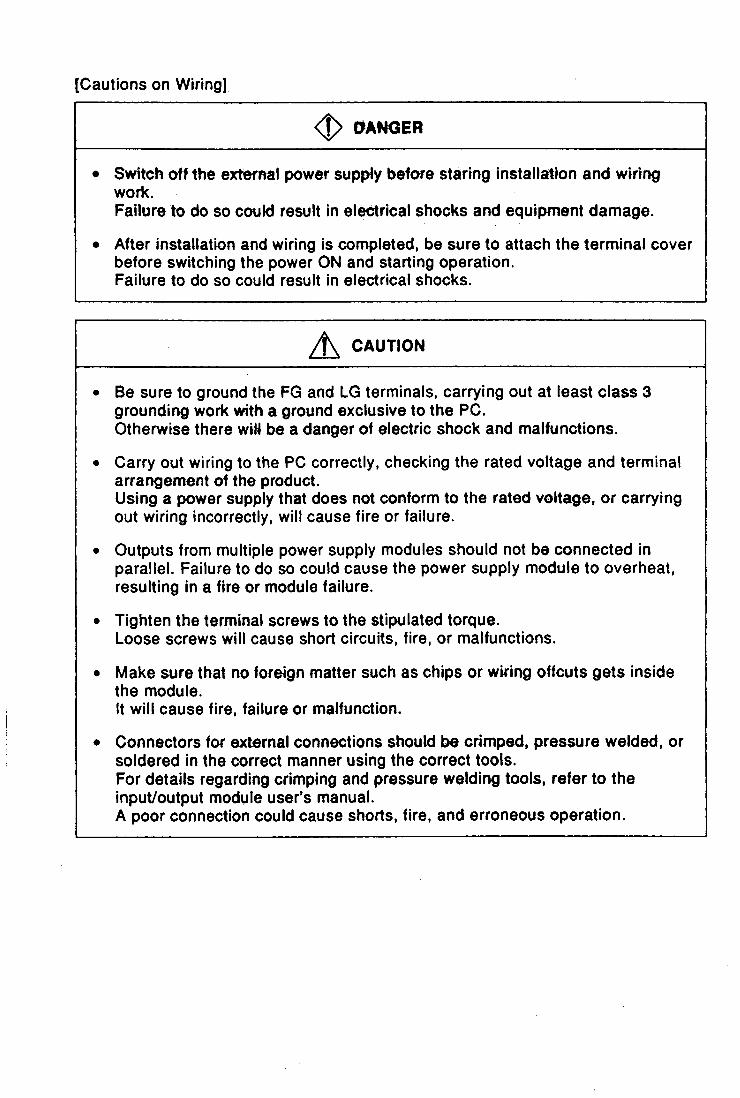
[Cautions on Wiring]
0 @ANGER
Switch off the external power supply before staring installation and wiring work. Failure to do so could result in electrical shocks and equipment damage.
After installation and wiring is completed, be sure to attach the terminal cover before switching the power ON and starting operation. Failure to do so could result in electrical shocks.
A CAUTION
Be sure to ground the FG and LG terminals, carrying out at least class 3 grounding work with a ground exclusive to the PC. Otherwise there wiH be a danger of electric shock and malfunctions.
Carry out wiring to the PC correctly, checking the rated voltage and terminal arrangement of the product. Using a power supply that does not conform to the rated voltage, or carrying out wiring incorrectly, will cause fire or failure.
Outputs from multiple power supply modules should not be connected in parallel. Failure to do so could cause the power supply module to overheat, resulting in a fire or module failure.
Tighten the terminal screws to the stipulated torque. Loose screws will cause short circuits, fire, or malfunctions.
Make sure that no foreign matter such as chips or wiring offcuts gets inside the module. It will cause fire, failure or malfunction.
Connectors fo r external connections should be crimped, pressure welded, or soldered in the correct manner using the correct tools. For details regarding crimping and pressure welding tools, refer to the input/output module user’s manual. A poor connection could cause shorts, fire, and erroneous operation.

[Cautions on Startup and Maintenance]
@ DANGER
Do not touch termiriats while the power is ON. This will cause malfunctiqns.
Make sure that the battery is connected properly. Do not attempt to charge or disassemble the battery, do not heat the battery or place it in a flame, and do not short or solder the battery. Incorrect handling of the battery can cause battery heat generation and ruptures which could result in fire or injury.
Switch the power off before cleaning or re-tightening terminal screws. Carrying out this work while the power is ON will cause failure or malfunction of the module.
/i\ CAUTION
In order to ensure safe operation, read the manual carefully to acquaint yourself with procedures for program changes, forced outputs, RUN, STOP, and PAUSE operations, etc., while operation is in progress. Incorrect operation could result in machine failure and injury.
Do not disassemble or modify any module. This will cause failure, malfunction, injuries, or fire.
Switch the power OFF before mounting or removing the module. Mounting or removing it with the power ON can cause failure or malfunction of the module.
When replacing fuses, be sure to use the prescribed fuse. A fuse of the wrong capacity could cause a fire.
[Cautions on Disposal]
A CAUTION
Dispose of this product as industrial waste.

REVISIONS 'The manual number is given on the bottom left of the back cover.
*Manual Number
IB (NA) 66619-A
Ravisbni First edition

1 . GENERAL MSCFHPTION ............................................ 1 - 1 . 1 - 11
1.1 Description of SFC Program . . . . . . . . . . . . . . . . . . . . . . . . . . . . . . . . . . . . . . . . . . . . . . 1 - 2 1.2 SFC (MELSAP3) Features . . . . . . . . . . . . . . . . . . . . . . . . . . . . . . . . . . . . . . . . . . . . . . . 1 - 4
3 . SPECIFICATIONS .................................................. 3 - 1 - 3 - 1 0
3.1 Performance Specifications Related to SFC Programs ......................... 3 - 1 3.2 DeviceLi st . . . . . . . . . . . . . . . . . . . . . . . . . . . . . . . . . . . . . . . . . . . . . . . . . . . . . . . . . . . . 3 - 3
3.4 Calculating the SFC Program Capacity . . . . . . . . . . . . . . . . . . . . . . . . . . . . . . . . . . . . . 3 - 9 3.3 Processing Time for SFC Program .. . . . . . . . . . . . . . . . . . . . . . . . . . . . . . . . . . . . . . . 3 - 5
4 . SFC PROGRAM CONFtGURAnON .................................... 4 . 1 . 4 . 78
4.1 List of SFC Diagram Symbds . . . . . . . . . . . . . . . . . . . . . . . . . . . . . . . . . . . . . . . . . . . . . 4 - 2 4.2 Steps . . . . . . . . . . . . . . . . . . . . . . . . . . . . . . . . . . . . . . . . . . . . . . . . . . . . . . . . . . . . . . . 4 - 4
4.2.1 Step0 (without step attribute) . . . . . . . . . . . . . . . . . . . . . . . . . . . . . . . . . . . . . . 4 - 4 4.2.2 Initial steps ................................................... 4 - 6 4.2.3 Dummy step Ix] . . . . . . . . . . . . . . . . . . . . . . . . . . . . . . . . . . . . . . . . . . . . . . . . . . 4 - 6 4.2.4 Coil HOLD s t e p m . . . . . . . . . . . . . . . . . . . . . . . . . . . . . . . . . . . . . . . . . . . . . 4 - 7 4.2.5 Operation HOLD step (without transition c h e c k ) l ..................... 4 - 9 4.2.6 Operation HOLD step (with transition check)m ...................... 4 - 11 4.2.7 Reset s t e p m .. . . . . . . . . . . . . . . . . . . . . . . . . . . . . . . . . . . . . . . . . . . . . . . . 4- 12 4.2.8 Block START step (with END Check) ............................. 4 - 14 4.2.9 Block START step (Without END check) H ........................... 4 - 15 4.2.10 BlockEND . . . . . . . . . . . . . . . . . . . . . . . . . . . . . . . . . . . . . . . . . . . . . . . . . . . . . 4-16
4.3 Transition Condition . . . . . . . . . . . . . . . . . . . . . . . . . . . . . . . . . . . . . . . . . . . . . . . . . . . 4 - 17 4.3.1 Serial transition . . . . . . . . . . . . . . . . . . . . . . . . . . . . . . . . . . . . . . . . . . . . . . . . . 4 - 17 4.3.2 Selection transition . . . . . . . . . . . . . . . . . . . . . . . . . . . . . . . . . . . . . . . . . . . . . . 4 - 19 4.3.3 Parallel transition . . . . . . . . . . . . . . . . . . . . . . . . . . . . . . . . . . . . . . . . . . . . . . . 4 - 22 43.4 Jump transition . . . . . . . . . . . . . . . . . . . . . . . . . . . . . . . . . . . . . . . . . . . . . . . . . 4 - 25 4.3.5 Transition processing with multiple initial steps ........................ 4 - 26 4.3.6 Precautions when creating sequence programs
for operation wtputs (m and.- Wtions . . . . . . . . . . . . . . . . . . . 4 - 27 4.4 Controlling SFC Programs by Instructions (SFC Control I n s t r u c t i o n s ) ............. 4 - 31
4.4.1 Step operation status check instructions (LD, LDI, AND, ANI, OR, O R I ) . . . . . 4 - 35 4.4.2 Forced transition check instruction .................................. 4 - 37 4.4.3 Block operation status check im&udon-(€Un) ........................ 4 - 39 4.4.4 Active step batch readout instructions (MOV, DMOV) . . . . . . . . . . . . . . . . . . . 4 - 40 4.4.5 Active step batch readout (BMOV) .................................. 4 - 42
4.4.7 Block STOP & RESTART instructions (PAUSE, RSTART) . . . . . . . . . . . . . . . 4 - 46 4.4.8 Step START & END instructions (SET, RST) ........................... 4 - 48 4.4.9 Forced transition EXECUTE & CANCEL ins&ructicms (SET, RST) . . . . . . . . . . 4 - 50
4.4.6 Block START & END bWN&nS~ ($ET, RST) ......................... 4 - 44
......... , ....................................................... .-.....--....-.... ....... . . . . - ...

4.4.10 ActiiestepchangeinstNctbR(SQM9) .............................. 4-52 4.4.1 1 Block switching instruction (BRSET) . . . . . . . . . . . . . . . . . . . . . . . . . . . . . . . . . 4-53 4.4.1 2 Program operation status check instruction . . . . . . . . . i .. , ............... 4-55 4.4.1 3 Subroutine call instruction’ (XCLL) . . . . . . . . . . . . . . . . . . . . . . . . . . . . . . . . . 4-56 4.4.14 Time check instruction (TMCHK) . . . . . . . . . . . . . . . . . . . . . . . . . . . . . . . . . . . 4-58
4.5 SFC Information Registers 4-59 4.5.1 Block STARTEND bit . . . . . . . . . . . . . . . . . . . . . . . . . . .,. .. - ............ 4-60 4.5.2 Step transition bd 4-62 4.5.3 Block STOP/RESTART bit . . . . . . . . . . . . . . . . . . . . . . . . . . . . . . . . . . . . . . . . 4-64 4.5.4 Block STOP mode bit . . . . . . . . . . . . . . . . . . . . . . . . . . . . . . . . . . . . . . . . . . . . 4-66 4.5.5 Continuous transitiin H . . . . . . . . . . . . . . . . . . . . . . . . . . . . . . . . . . . . . . . . . . 4-67 4.5.6 ‘Number of active steps” register . . . . . . . . . . . . . . . . . . . . . . . . . . . . . . . . . . . 4-68
4.6 Step Transition Watchdog Timer . . . . . . . . . . . . . . . . . . . . . . . . . . . . . . . . . . . . . . . . . . 4-69 4.7 SFC Operation Mode Setting . . . . . . . . . . . . . . . . . . . . . . . . . . . . . . . . . . . . . . . . . . . . 4-71
4.7.1 SFC program START mode ....................................... 4-72 4.7.2 Block 0 START condition . . . . . . . . . . . . . . . . . . . . . . . . . . . . . . . . . . . . . . . . . 4-72 4.7.3 Output mode at M o c k STOP .. . . . . . . . . . . . . . . . . . . . . . . . . . . . . . . . . . . . . . 4-73 4.7.4 Periodic execution bled< setting . . . . . . . . . . . . . . . . . . . . . . . . . . . . . . . . . . . . 4-74 4.7.5 Operation mode at double block START .. . . . . . . . . . . . . . . . . . . . . . . . . . . . 4-75
. . . . . . . . . . . . . . . . . . . . . . . . . . . . . . . . . . . . . . . . . . . . . . . . > a i ..
. . . . . . . . . . . . . . . . . . . . . . . . . . . . . . . . . . . . . . . . . . . . . . .
4.7.6 Operation mode at transition to active step (double step START) . . . . . . . . . . 4-76
5 . SFC PROGRAM PROCESSING SEQUENCE ............................. 5 . 1 . 5 . 14
5.1 Overall Program Processing . . . . . . . . . . . . . . . . . . . . . . . . . . . . . . . . . . . . . . . . . . . . . . 5 - 2 5.1.1 Program processing sequence . . . . . . . . . . . . . . . . . . . . . . . . . . . . . . . . . . . . . . 5 - 2 5.1.2 Execution type designation by instructions ............................. 5 - 4 5.1.3 SFC program for program execution management ...................... 5 - 6
5.2 SFC Program Processing Sequence . . . . . . . . . . . . . . . . . . . . . . . . . . . . . . . . . . . . . . . 5 - 8 5.2.1 SFC program execution cycle . . . . . . . . . . . . . . . . . . . . . . . . . . . . . . . . . . . . . . . 5-8 5.2.2 Block execution sequence ......................................... 5 - 9 5.2.3 Step execution sequence . . . . . . . . . . . . . . . . . . . . . . . . . . . . . . . . . . . . . . . . - 5 -10 5.2.4 Continuous transition OWOFF operation ............................. 5-12
6 . SFC PROGRAM EXECUTION ......................................... 6 . 1 . 6 . 12
6.1 SFC Program START and END ........................................... 6 - 1 6.1.1 SFC program rewmptive START procecbre ........................... 6 - 2
6.2 BlockSTARTandEND ................................................. - 6 - 4 6.2.1 BlodcSTARTmethods ............................................ 6 - 4 6.2.2 BlockENDmethods ............................................. - 6 - 5
6.3 Block Temporary Stop & Restart Methods ................................... 6 - 6 6.3.1 BlockSTOPmethod~ ............................................. 6 - 6 6.3.2 Restarting a stopped block ......................................... 6 - 8
6.4 Step START (Activate) and END (Deactivate) Methods . . . . . : . . . . . . . . . . . . . . . . . . . 6 - 9 6.4.1 Step START (activate) methods ..................................... 6 - 9 6.4.2 Step END (deactivate) metkds .................................... 6-11 6.4.3 C h m g h an active step status ..................................... 6-12
f
1 1
#
. 1
1

APPENDIX 1 SfEClAL RELAY AND SPEClM REGISTER LIST ...................... APP . 1 1.1 " S " ' ~ f R 8 4 ~ ................................................. APP-1 1.2 "SD*Special Rmm . . . . . . . . . . . . . . . . . . . . . . . . . . . . . . . . . . . . . . . . . . . . . . . APP-4
APPENDIX 2 MELSAP-II AND MELSAP3 COMPARISON . . . . . . . . . . . . . . . . . . . . . . . . . . . . APP - 6
. C

1 GENERAL DESCRIPTION MELSEC-QnA
This manual diseudses the specifications, functions, instructions, and pro- gramming procedures used to program the MELS€G= QW-Sl , 03A, and Q4ACPU (hereafter referred to as QnACPU) with an SFC program using the MELSAP3 function. "SFC" is an abbreviation for 'Sequential Function Chart", and represents a program format in which a sequence of control operations is split into a se- ries of steps, enabling a clear expression of the program execution se- quence and execution conditions. MELSAP3 conforms to the IEC standard for SFC. In this manual, the se- quential function chart is referred to as 'SFC" (program, diagram).
IRelated Manuals1
Manual Name I Manual Number
QnACPU Guidebook Aimed at people using QnACPU for the first time. Describes procedures for everything from creating programs and writing created programs to the CPU, to debugging. Also describes how to use the QnACPU most effectively. QPA(Sl)IQSA/Q4ACPU User's Manual Describes the performance, functions, and handling of the Q2ACPU(S1), Q3ACPU, and Q4ACPU, and the specifications and handling of memory cards and base units. (Purchased separately) QnACPU Programming Manual (Common Instructions) Describes how to use sequence instructions, basic instructions, and application instruc- tions. (Purchased separately)
18-66606
18-66608
18-666 1 5
QnACPU Programming Manual (Special Function) Describes the dedicated instructions for special function modules available when using the Q2ACPU(S1), QBACPU, and Q4ACPU. (Purchased separately) QnACPU Programming Manual (AD57 instructions) Describes the dedicated instructions for controlling an AD57(S1) type CRT controller module available when using the Q2ACPU(S1), QSACPU, or Q4ACPU. (Purchased separately) QnACPU Programming Manual (PID Control instructions)
Q2ACPU(S1), WACPU, or Q4ACPU. Describes the dedicated instructions for PID control available when using the 18-66618
(Purchased separately) MELSECNET/lO Network System (for QnA) Reference Manual Describes the general concept, specifications, and part names and settings, for MEL- SECNETI10. (Purchased separately) Type SWOIVD-GPPQ GPP Function Operating Manual (OFFLINE) Describes the how to create programs and print out data when using SWOIVD-GPPQ, and the offline functions of SWOIVD-GPPQ such as file maintenance. (Supplied with the product) Type SWOIVD-GPPQ GPP Function Operating Manual (ONLINE) Describes the online functions of SWOIVD-GPPQ, including the methods for monitoring and debugging. (Supplied with the product) Type SWOIVD-GPPQ GPP Function Operating Manual (SFC) Describes the system configuration, performance specifications, functions, system startup procedure, SFC program editing method, monitoring method, printout method, 18-66625 and error messages, for MELSAP-3. (SUDDlied with the DrOdUCtl
18-666 16
18-666 1 7
18-66620
18-66623
18-66624
1 - 1
1 .,.GEblER.AL. - j.. A I , DESCRIPTION
1.1 Deecriptbon of SFC Program
M L S E G & A
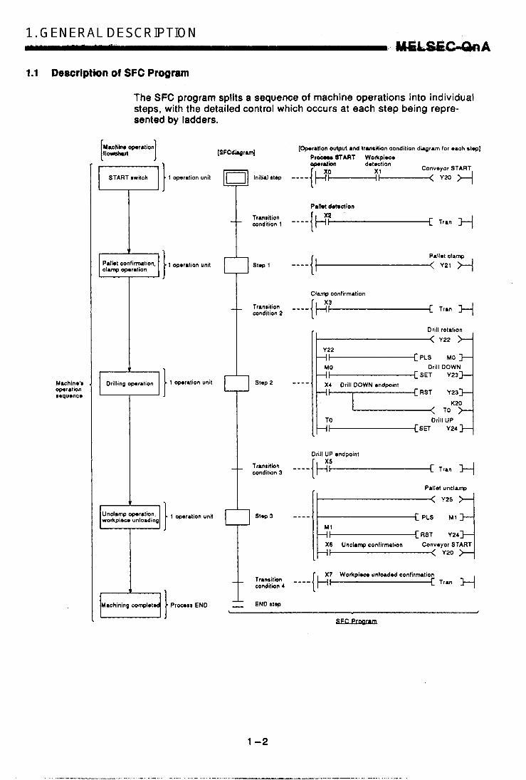
The SFC program splits a sequence of machine operations into individual steps, with the detailed control which occurs at each step being repre- sented by ladders.
Machine'$ operation sequence
[;soperation] [SFCdiqrw [Cpmratlon oulpvt and transition condition diagram for each step]
Conveyor START START switch 1 operation unit [Dl Initial atop ----{I-$-?-< Y20 H I
I
PI- START W0rlrpi.c. CQWrlion detoction
Cam ddedion _ _ ~rmraion ---_I b m condition 1 I-[ Tran
v Palbt confirmation, 1 step1 ----{ clamp operation
1 , yl;;lampH
Clamp confirmalion
_ _ Transilion ----[I 7; [ T~~~ -+/ condition 2
Drill rotation
I-[ SET Y23
\-=RST Y23
c;'-'sEl Y24 4 Drill UP
t X7 Workpiece unloaded confirmation Transition - - - - [ I-[ Tran -+/ condition 4
1- - ENDrtep L
EuKwam

The SFC program performs a sequence of!opsrtHbbei .beginahgrimm'%he "initial" step, proceeding to each subsequent step as the transition condi- tions are satisfied, grid pfiding'at the MEW" stap.
(1) When the SFC program is starteditha 'initial" step is executed first.
(2) Execution of the initial step continues until transition condition 1 is satisfied, When this translfion condition is satisfied, execution of the initial step is stopped, and processing proceeds to the step which follows the initial step.
Processing of the SFC program continues from step to step in this manner until the END step has been executed.
I i
1-3

1. GENERALSDESCRIPTION . E ~ . . . , ' , , \ . * . 8 . . . . - .
1.2 SFC (MELSAP3) Features
(1) Easy to design and. maintain systems
n control unit for
Step transition
w o r d process
Because control of the overall system and, each station, as well as the machines themselves, corresponds on a one-to-one basis with the blocks and steps of the SFC program, systems can be designed and maintained even by those with relatively little sequence program expe- rience. Moreover, programs designed by other programmers using this format are much easier to decode than sequence programs.
F l conlrol unit control unit control unit
I Transfer machine I I ' I
Overall system (SFC program)
Station 2 coMmt vnit (block 2)
Station 3 control unit
(2) Requires no complex interlock circuitry
Interlock circuits are uqed only in the operation output programs for each step. Because intertocks between steps are not required, it is not necessary to consider'interlocks with regard,to the overall system.
1 T L
I I i LS-D I I
I I - #.
Cy w m / (Hdslodc RETRACT (Machining (Machining (Curiago ADVANCE endpoint) START) END) endpoint) (Carriage RETRACT wdpoint)
LS10
I LSQ LS1 LS2 LS-F LS-R I
1 - 4

T
+ I
SFC program
A. chol*n in tho SFC p q p m at IoH. tho rt.pr roquire no 'op.r.tion compktrd' intorlock contact with tho W o u r 8t.p. With a sonvontiond soquonco program carriago FORWARD (Y20) and dam DOWN (Y21) inlodock conlacto would k roquirod a1 the ladder u r d for lho hoadrtock ADVANCE.
(3) Block and step configurations can easily be changed for new control applications
A total of 320 blocks can be used in an SFC program, with 512 steps in each block. A total of 4k sequence steps can be created in each block of the ladder diagram programs for operation outputs and transition conditions. Reduced tact times, as well as easier debugging and trial run operations are possible by dividing the blocks and steps so as tq obtain the optimum configuration for system-of-units used for machine operation.
320 blocks
Operation output program
.. ,
912 Mmps
4k sequence steps per block for operation outputs and transition conditions
i
I
c
Block 1 Block 3 19 + step 1 + +
9 step 2 9 Step 2
1 -5
1. * I GEN,.EFJAL DESCRIPTION . c.&hii&SGOaA
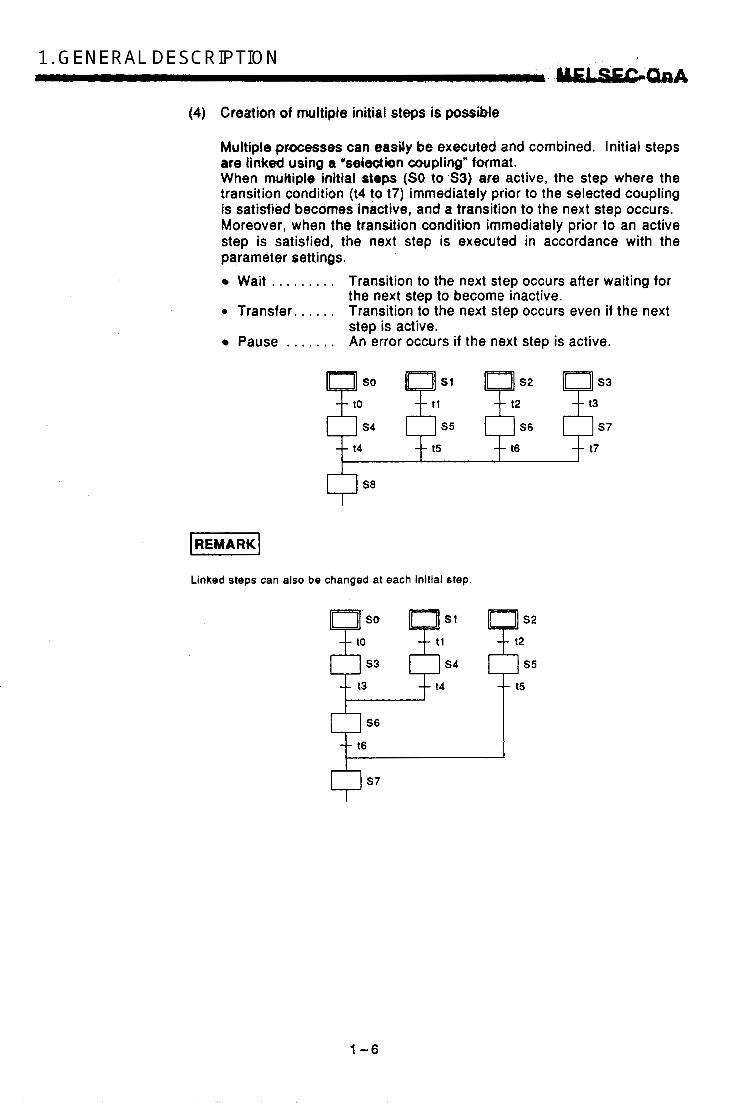
(4) Creation of multiple initial steps is possible
Multiple pmcesses can easily be executed and combined. Initial steps are linked using a 'selec4ion coupling" format. When multiple initial steps (SO to S3) are active, the step where the transition condition (14 to 17) immediately prior to the selected coupling is satisfied becomes inactive, and a transition to the next step occurs. Moreover, when the transition condition immediately prior to an active step is satisfied, the next step is executed in accordance with the parameter settings.
Wait . . . . . . . . . Transition to the next step occurs after waiting for
0 Transfer. . . . . . Transition to the next step occurs even if the next
Pause . . . . . . . An error occurs if the next step is active.
the next step to become inactive.
step is active.
so
s4 -- t4
S8
Linked steps can also be changed at each initial step.
1 -6
I

(5) Prggram design is m y due to a weaith.ef stepattributes
.,A verietly d,rtep attributes carr.kassigned to each step. Used singly -.for:a g" aonW -ation, oeinimbinalion, these attributes greatly
0 .&$of GOLD $tgps, wy',t&ir.'operations a) Coil'HOLD'4t44p {W) ' '
/ ' dm@@ prog&mge$ign-~proccrbutW: . .
, . . , . - . 0 Whm the transition condition is p-.ylo d satisfied, the coil output status is
I maintained regardless of the 1 a q - n ON/OFF status of the interlock "'416 J: cdndition (XO). [Tr.ns%n condition sat is f i ) 0 Transition will not occur even if
the transition condition is satis-
c Step which is active due t ~ n r i l i oondhion k g
fied again. d) 0 Convenient for maintaining an output until the block in question i 6 . d
t is completed (hydraulic motor output, pass confirmation signal,
4
i I
t
etc.). b) Operation HOLD step (no transition check) ( m)
Operation output processing K- ~ 1 0 4 continues even after a step tran-
xo (Y10) ONOFF switching occurs sition occurs, and coil output
Y10 J-t-Jl- in accordance with the interlock condition (XO) ON/OFF status.
0 Transition will not occur if the transition condition is satisfied
0 Convenient for repeating the same operation (cylinder ad- vancdretract, etc.) while the relevant block is active.
1-7
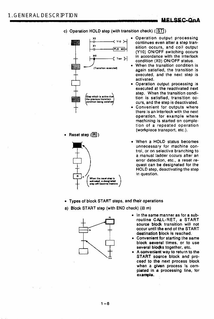
1. . ’ , , G.ErJEWL. i. DESCRIPTION . , uAEm c) Operation HOLD step (with transition check) (I)
Operation output processing continues even after a step tran- sition occurs, and coil output (Y10) ON/OFF switching occurs in accordance with the interlock condition (XO) ON/OFF status.
0 When the transition condition is again satisfied, the transition is executed, and the next step is activated. Operation output processing is executed at the reactivated next step. When the transition condi-
_li
0
MO m [ TrUl
(Transition oxocvtd)
Slop which is activo duo lho pWioU8 lrrnrilion tion is satisfied, transition oc- condition being salhfiod curs, and the step is deactivated.
Convenient for outputs where there is an interlock with the next operation, for example where machining is started on comple- t ion of a repeated operation (workpiece transport, etc.).
Reset step (m ) When a HOLD status becomes unnecessary for machine con- trol, or on selective branching to a manual ladder occurs after an error detection, etc., a reset re- quest can be designated for the HOLD step, deactivating the step in question.
When the r o a d stop is . b i v r t d . a d u p n W step d l kcanw iruttiv.
.I.
Types of block START steps, and their operations a) Brock START step (with END check) (e m)
VIm t I I ,
1-8
In the same manner as for a sub- routine CALL-RET, a START sowce blodk transition will not occur untll the end of the START destination block is reached. Convenient for starting the same block several times, or to use several w s together, etc.
0 A.mvenient way to return to the START source block and pro- ceed t p the next process block when a g i k n process is com- pleted in a processing line, for example.

b) Block START step (Without END check) (€I m) Even if the START destination block is active, a START source block transition will occur if the transition conditions for the block START step are satisfied. At such times, processing of the START destination block will be continued to the block END.
0 By starting another block at a
tion block can be controlled inde- pendently and asynchronously with the START source block un- til processing of the current block is completed.
- given step, the START destina-
(6) A given function can be controlled in a variety of ways according to the application in question
Block functions such as START, END, temporary stop, restart, and forced activation and ending of specified steps can be controlled by SFC diagram symbols, SFC control instructions, or by SFC information registers. 0 Control by SFC diagram symbob
, . . . . Convenient for control of automatic operations with easy sequential control.
0 Control by SFC instructions . , . . . Enables requests from program files other than the SFC, and
is convenient for error processing, for example after emergency stops, and interrupt control.
Control by SFC information registers . . . . . Enables control of SFC peripheral devices, and is convenient
for partial operations such as debugging or trial runs. Functions which can be controlled by these 3 methods are shown below.
I-- Control Method Function Control I SFC Information Register8
Block START Mlth END wait) B m - -
1
glock SiART 1 B m I SET BLm 1 Block STARTIEND bit 1Mtbut END wait) ON
Block END I RST BLm 1 Block STARTIEND bit OFF
Block $TOP I PAUSE BLrn I Block STOPIRESTART bit ON
1 RSTART BLm 1 Block STOPIRESTART bit OFF
foiceiditep SET Sn acWaUon
- SCHG Kn -
Forced step END RST Sn SCHG Kn
1-9


2. SYSTEM ,CONFIGURATION UlSEGUnA 2. SYSTEM CONFIGURATION
(1) Applicabte CPU models
MELSAP3 (SFC program) can be run by the following CPU modek.
. -
Q2ACPU QPACPU-S1 Q3ACPU Q4ACPU
(2) Peripheral devices for the SFC program
SFC program creation,, editing, and monitoring operations are conducted at the following peripheral devices.
I Peripheral Device Software Yodel Name Package Name I Remarks I
I I I For details regarding the system I I IBM PClAT SWO,VD-GPPQ configuration and environment settings,
etc., refer to the ‘GPPO Operating Manual’ (OFFLINE). I
(3) Memory card
The memory card shown below is required for SFC trace operations.
, -,, ., . 0 1 M E N - L J L A L J
T Memory type Memory size
For details regarding the memory card, refer to the QnACPU Users Manual.
3. SPECIFICATIONS
The performance specifications lor SFC programs are described in this section.
3.1 Perfomence Specificatians Related to SFC Programs
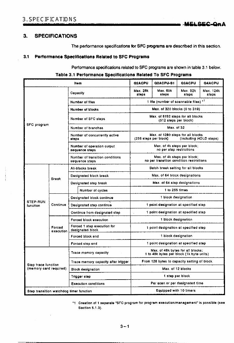
Performance specifications related to SFC programs are shown in table 3.1 below. Table 3.1 Performance Specifications Related To SFC Programs
Item
Capacity
Number of files 1 file (number of scannable files) *’ Max. of 320 blocks (0 to 319) Number of blocks
Number of SFC steps Max. of 8192 steps for all blocks (512 steps per block)
SFC program Max. of 32
Max. of 1280 steps for all blocks (256 steps per block) (including HOLD steps)
Number of branches
Number of concurrently active steps
Number of operation output sequence steps
Max. of 4k steps per block; no per step restrictions
Number of transition conditions sequence steps
Max. of 4k steps per block; no per transition condition restrictions
All-blocks break I Batch break setting for all blocks
Designated block break Max. of 64 block designations
Designated step break Max. of 64 step designations
~~ ~ ~~ ~ ~~ ~
Break
I Number of cycles I 1 to 255 times
Designated block continue I 1 block designation STEP-RUN function
-r
Designated step continue
Continue from designated step
1 point designation at specified step
1 point designation at specified step
Continue
c: Forced block execution I 1 block designation
Forced 1 step execution for designated block 1 point designation at specified step Forced
execution Forced block end
1 point designation at specified step Forced step end
1 block designation
Trace memory capacity Max. of 48k bytes for all blocks; 1 to 48k bytes per block (1 k byte units)
I
Trace memory capacity after trigger From 128 bytes to capacity setting of block Step trace function (memory card required) Block designation I Max. of 12 blocks
Trigger step ~ ~~
I 1 step per block
Execution conditions ~~~
Per scan or per designated time
SteD transition watchdog timer function I Equipped with 10 timers
‘1 Creation of 1 separate ’SFC program for program executionlmanagement’ is possible (see Section 5.1.3).
3-1

3. SPECIFICATIONS MELSIEG-UnA
,
The relationship between the CPU memory's program capecity and the number of files is shown below.
I
1 T T l I i e (no Multiple SFC program programs) fi les possible
I I I I I I I I I I I I I I I I I I
I I I I
I
I I I I I I I I I I I I I I 1 I I I I
I I
WAIT program
I I I I I I
1 1 I Low-speed I program
e Multiple program files possible I (no SFC pr6grams)
I I I
I
0 Max. total of 124 programs possible. (Registration is by parameter setting)
0 The program capacity varies according to the CPU type as shown below.
0 Q2ACPU.. . . . . . . . . Max. of 28k steps. e Q2ACPU-SI.. . . . . . Max. of 60k steps. 0 Q3ACPU.. . . . . . . . . Max. of 92k steps. 0 Q4ACPU. . . . . . . . . . Max. of 124k steps.
The SFC program can execute only 1 file. To o x w t e an SFC program whicb,is in Ye wait status, switctr the SFC pragrem being scanned to the wait btatus, then scaa tbo pogram in question.
3 - 2

3.2 Device List
Devices which can be used.for the SFC program's transition conditions and operation outputs are shown in table 3.2 below.
Table 3.2 Dsttice List
Internal system
Argument input Bll FXO €o FX15
Argument output Bit FYO to FY15
Argument register Word FDO to FD4 Fixed
1 Special relay 1 811 1 SMO to SM2047 I Special register Word SDO to SD2047
1 Latch relay 1 Bit 1 LO to L8192 I Annunciator FO to F2047
1 1 I I
Edge triggered I relav I VO to V2047 t I t I
Link relay I I BO to BlFFF Variable
internal user Data register Llnk register
. I Word DO to 12287
wards 28.75 K WO to WlFFF total of ' within a
I Normal timer I Bit, word TO to T2047 .. -. --
Retentive timer
co to c1023 Bit, word Counter
ST0 to ST2047
I Special link relav I I SBO to SBlFF
L I c I 1 1 Bit I SWO to SWlFF I Speclal link register
I I SO to S51111 block Step relay (8192 points for all
blocks)
Bit
Link input JO\XO to JO\XlFFF
Link output JO\YO to JO\YlFFF
Unk direct (NETl10) Link special
Link relay
relay
JO\BO to JO\BlFFF
register Llnk specid
JO\WO to J o w l FFF Link register
JO\SBO to JO\SBlFF Fixed
Word JO\SWO to JO\SWlFF
unit I Butler reglOler I Word I UO\GO to U0\016383 I Fixed direct
index r8glster I Index r e g b t e r I ' Word I 20 to 215 I
Rem8rks
Sub-routine with argument
Sub-routine with argument (1 point, 4 words)
Direct orocessincl at DX Direct processing at DY
T and ST by parameter
Contact and coil by bit.
Contact and coil by bit.
setting.
Exclusively for SFC program
Present at each link unit
Present at each installed soeclal unit
3-3

3. SPECIFICATIONS I .
3 .!M€l.SEGOnA
Claralf lcat lon
File register
Other
Constants
Dovlce TY P I
File register Word
SFC block SFC transition device Network No. 110 No. Decimal constant Hexadecimal constant - Real number constant Character string constant
Bit
-
Exprrrr lon Remarks
I FIX& used RO to R32767 When block switching is
ZRO to ZR1042431 I For serial Nos. -1 Fixed 1 Exclusively for SFC program BtO to EL319
TRO to TR511
'ABC123', etc. I
. . -.
..3 - 4

3.3 Processing time for SFC Program
The time required to process the SFC program is discussed below.
(1) Method for calculating the SFC program processing time
The processing time for the SFC program comprises the processing time for operation outputs and transition condition instructions, and the sys- tem processing time. SFC program ration oulput/transition condition system processing processing time = ( Z m c t b processing time ) + (time
(a) Processing time for operation output & transition condition instruc- tions
Operation outpWtransition condition instructions processing time
(Only when transition condition is satisfied)
0 Processing time for operation output instructions . . . . . . . . . . . . . . . . . . . . . . . . Total processing time for
instructions used for operation outputs at all active steps.
0 Processing time for transition condition instructions . . . . . . . . . . . . . . . . . . . . . . . . Total processing time for
instructions used for transition conditions at all .active steps.
For details regarding the processing times for operation outputs and transition condition instructions, refer to the QnA Program- ming Manual (Common Instructions).
(b) Method for calculating the system processing time System processing time =
[SFC END processing time] + [active block processing time] x [number of active blocks] + [processing time for inactive blocks] x [number of inactive blocks] + [processing time for nonexistent blocks] x [number of nonexistent blocks] + [active step processing time] x [number of active steps] + [processing time for active step transition conditions] x [number of active step transition conditions] + [processing time for steps where transition conditions are satisfied] x [number of steps where transition conditions are satisfied] Number of active blocks. . . . Total number of active blocks. Number of inactive blocks . . Total number of inactive blocks.
0 Number of nonexistent blocks ........................ Total number of parameter-
designated blocks which have no programs.
.3-5
3. SPECIFICATIONS . - . .? 1 ” .
J JI11ELSEGQnA Number of active steps .... Total number of active steps in all
blocks. Number of active step transition conditions
. . . . . . . . . . . . . . . . . . . . . . . . Total number of transition conditions for all active steps in all blocks.
Number of steps where transition conditions are satisfied ........................ Number of steps (in all blocks) where
the transition conditions have been satisfied, resulting in an operation output OFF.
(2) CPU models and corresponding system processing times
Item I Q4ACPU I Q3ACPU I QPACPU
Active block processing I 20.3 pS I 40.5 pS I 54.0 pS ~ -~~~~
Inactive block processing
19.6 pS 14.7 pS 7.4 ps Processing,of active step transition conditions
8.4 ps 6.3 pS 3.2 pS Actlve step processing
5.5 ps 4.1 pS 2.1 ps Nonexistent Mock processing
10.5 pS 7.9 ps 4.0 pS
Processing of steps
satisfied conditions are
step designation where transition Without a HOLD 7.8 ps
5.6 pS 4.2 pS 2.1 ps
20.8 ps 15.6 pS
With a HOLD step designation
At initial START
260.0 pS 195.0 pS 97.5 ps At resumptive START
38.0 pS 28.5 pS 14.3 ps SFC END processing
‘HOLD steps’ include both coil HOLD steps and operation HOLD steps (with or without transition checks).
Example of SFC system processing time calculation
Using the Q4ACPU as an example, the processing time for the SFC system is calculated as shown below, given the following conditions.
Designated at initial START 0 Number of active blocks: 30
(active blocks at SFC program) Number of inactive blocks: 70 (inactive blocks at SFC program) Number of nonexistent blocks: 50 (number of blocks between 0 and the max. created block No. which have no SFC program) Number of active steps: 60
- (active steps within active blocks) Active step transition conditions: 60
3 -6

0 Steps with satisFied-transni~coRditions: 10 (active steps (no HOLD steps) with satisfied transition conditions) SFC system process time;= 14.3 + (20.3 x 30) + (4.0 x 70) + (2.1 x 50) +
+ (3.2 X 60) + (7.4 X 60) + (7.8 X 10) = = 1722.3 pS = 1.72 ms
In this,case, oakutation using the equation shown above results in an SFC system processing time of 1.72 ms. With the Q3ACPU, given the same conditions, the processing time would be 3.41 ms, and with the mACPU, it would be 4.56 ms. The Scan time is the total of the following times: SFC system processing time, main sequence program processing time, SFC active step transi- tion condition ladder processing time, and CPU END processing time. The nurnbac of. active steps, the. numb-er of transition conditiws,. and the number of steps with satisfied transition conditions varies according to the conditions shown below. 0 When transition condition is unsatisfied 0 When transition condition is satisfied (without continuous transition) 0 When transition condition is satisfied (with continuous transition) The method for determining the number of the above items is illustrated in the SFC diagram below.
b step 1 Transition condition 1
stop 2 Step 6
Transition Transition condition 2 condition 5
( t l step 3 step 7 Transition condition 6 Step 8
Transition condition 7 Step 9
I Transition condition 8
step 10
1
I
I
3-7

3. SPECIFICATIONS -. . . . . . . . M€LS€C?QnA
a) When transition condition is not satislfied If steps 2 and 6 are both active, but transition conditions 2 and 5 are. not satisfied:
Number of active steps. . . . . 2 (steps 2 & 6) Transition conditions. . . . . . . 2 (transition conditions 2 & 5 ) Number of steps with satisfied transition conditions
........................ 0
b) When transition conditions are satisfied If steps 2 and 6 are active, transition conditions 2 and 5 are satisfied, and transition conditions 3 and 6 are not satisfied: (With continuous transition) Number of active steps . . . . 2 (steps 2 & 6) Number of transition conditions
Number of steps with satisfied transition conditions (with continuous transition)
Number of active steps . . . . 4 (steps 2, 3, 6, 7) Number of transition conditions
........................ 2 (transition conditions 2 & 5 )
. . . . . . . . . . . . . . . . . . . . . . . . 2 (steps 2 & 6)
. . . . . . . . . . . . . . . . . . . . . . . . 4 (transition conditions 2, 3, 5 , 6)
........................ 2 (steps 2 & 6) Number of steps with satisfied transition conditions
If steps 2 and 6 are active, and transition conditions 2,3,6,7 are all satisfied (without continuous transition): Number of active steps . . . . 2 (steps 2 & 6) Number of transition conditions
Number of steps with satisfied transition conditions (with continuous transition)
Number of active steps . . . . 6 (steps 2 to 4 & 6 to 8 ) Number of transition conditions
Number of steps with satisfied transition conditions
........................ 2 (transition conditions 2 & 5 )
........................ 2 (Steps 2 & 6)
........................ 6 (transition conditions 2 to 4 & 5 to 7)
........................ 4 (steps 2,3,6,7)
3-8 .

3.4 Calculating the SFC P m g m Caproity
In order to express the SFC diagram using instructions, the memory capacity shown betow is required. The method for calculating the SFC program capacity and the number of steps when the SFC diagram is expressed by SFC dedicated instructions is described in this section.
(1) Method for calculating the SFC program capacity
SFC program capacity = 2 + 8 Xmax* lock 0 cmacity) + Mock 1 capacity) +...+ (block n camcity1
T [ block NO.+ 1 Number of blocks being used
L SFC program START (SFCP) an6 ENb (SFCPEND) instructions
Capacity of blocks = 2 + by sFc mtd W C diagram instructions 1s + (operation output total for all steps) + T + (total number of transition conditions)
I '
L I As shown below
Block START (BLOCK BLm) andEND {BEND) instructions
Number of steps where SFC diagram is expressed by SFC dedi- cated instructions
------- + I 0 Step (0, €I ) I I
~~
3 sequence steps (+) for step START (STEP: l Sn) and END (SEND) instruc- . - - - - - - , - - - - - - I tions.
Transition conditions (+) - - - - - - - - - - - - - L - - - - - - + a) For serial transition or selective branching coupling
4 sequence steps for transition START instruction (TRAN; z TRn) and tran- sition destination instruction (TSET Sn).
b) For parallel branching Total number of steps for the transition START instruction (TRAN; TRn), and transition destination instructions (TSET Sn) for the number of parallel branches in question.
_- - - - - - - - - - - - - I I.------+
-------* c) For parallel cpupling - - - - - - - - - - - - - - I Total number of steps for the transition START instruction (TRAN; l TRn), and
the transition destination instructions (TSET Sn) and coupling check instruc- tions (TAND S h ) for the (number of parallel branchings in question) - 1. - - - - - - - - - - - - - - , -
.------ * Jump &), block end (I) Calculated as step 0 because it is included in the previous transition condition.
Operation outputs for each step: The capacity per step is as follows e 0 Total number of sequence steps for all instructions. i
(For detalls regarding the number of sequence steps for each instruction, refer tothe QnA Programming Manual (Common Instructions)
0 Transition conditions: The capacity per transition condition is as follows
(Foi Walk regardlng the number of sequence steps for each instruction, refer to the QnA Programming Manual (Common Instructions)
!
Total number of sequence steps for all instructions.
3-9

3. SPECIFICATIONS 1. I UIELSEC-QnA
(2) Number of steps required for expressing the SFC diagram 85 SFC dedicated instructions
The following table shows the number of steps required for expressing the SFC diagram as SFC dedicated instructions.
Name Required Number of Steps Descrlptlon Ladder Expression
SFCP START
END Number of steps = 1 instruction per program Indicates the SFC program [SFCPEND] SFCP END START Number of steps = 1 instruction , per program Indicates the SFC program [SFCP]
Block START [BLOCK BLm] instruction 1 Number of s tem - 1 I Indicates the block START I 1 per block
Block END instruction
[BEND] Number of steps = 1 indicates the block END 1 per block
Step START instruction
[STEP: si] In,d,icates the step START Number Of steps the step attribute)
(gL , varies according to 1 per step
Indicates the transition Transition START instruction
START [TRAN; TRj] (*: varies according to Number of steps = 2 1 per transition condition
I the step attribute) - Coupling check
per parallel coupling occurs at parallel coupling Number of steps = 2 instruction '[Number of parallel couplings] - [I ] ' "Coupling completed" check [TAND Si]
I I I For serial transitions and selection Transition transitions, 1 per transition condition; designation
number of steps is the same as the instruction for parallel branching transitions, the Designates the transition [TSET Si]
Number of steps = 2 destination step number of parallel couplings
1 per step Stop END instruction
Indicates the step (L [SEND] transition EIQD Number of steps - 1
3-10

The SFC program symbols, control instructions, and information registers which comprise an SFC program h ~ 8 discussed in this section.
(1) 4s S~OYR!?Q!Q~, , a n SFC program consists. of a.n i*iti,a!,, s,tep, transition conditions, intermediate steps, and an END step. The datalbeqhning from the initial step and ending at the END step is referred to as a block.
,
- Initial step
Transition condition 1
--- Transition
condition condition 2 -- c-- Transttion Transition
Step 1 Step
condition
step 2 step
I I
-- END step i d
+ Block
,
(2) SFC program operation begins at the initial step, and proceeds to each of the successive 'bps as each transition condition is satisfied. This operation sequence ends when t h e END step is reached.
(a) When the SFC program is started, the initial step is executed first. During initial step processing, the next transition condition ("transi- tion condition 1" in the above illustration) is checked to determine whether or not it is satisfied.
(b) Initial step processing continues until transition condition 1 is satisfied. When transition condition 1 is satisfied, initial step processing stops, and processing of the next step ("step 1" in the above illustration) begins. During step 1 processing, the next transition condition ("transition condition 2" in the above illustration) is checked to determine whether or not it is satisfied.
and processing of the next step ("step 2" in the above illustration) begins.
(c) When transition condition 2 is satisfied, step 1 processing stops,
Processing of the SFC program continues in this manner, executing the steps in order until the END step is reached.
4-1

4. SFC PROGRAM I. 1 . CONFIGURATION . I "c-
4.1 List of SFC Diagram Symbols
Class
Step
Name
Initial step
Dummy initial step
Coil HOLD initial step When step
Operation HOLD step (without No. is '0' transition check) initial step Operation HOLD step (with transition check) initial step
Reset initial step
Initial step Dummy initial step I
I
Operation HOLD step (with transition check) initial step
Coil HOLD step
Operation HOLD step (without Steps other
Operation HOLD step (with than 'initial'
transition check) step
Block START step (with END
Block START step (without E N D check)
SFC Diagram Symbol Quanllly
1 of these steps per block
m i I
Max. of 31 steps per block
I
Max. of 512 steps per block, including initial step
E i BLm I i BLm I
4-2

4. SFC PROGRAM CONFIGURATION . I
. , .‘+ru-
CI.88
Transition
Block END
Name
ierial transition
Moctive branching
Selective branching - parallel branching
Selection coupling
Selection coupling - parallel branching
Parallel branching
Parallel coupling
Parallel coupling - parallel brenchlng
Parallel coupling - selective branching
Parallel coupling - selective coupling
Jump
Block END
f a
Can be used more than once Der block

4. SFC PROGRAM CONFIGURATION U M S E C l O n A
4.2 Steps
Steps are the basic units which comprise a block, and they represent the units in which the SFC program is executed.
(1) Each step consists of operation outputs. A maximum of 512 steps per block can be designated (total of 8192 steps for all blocks).
(2) Step numbers are assigned to the steps (either automatically or by user designation) when the SFC program is created. The step numbers are used for monitoring step processing, and for designating a forced START or END by SFC control instruction.
4.2.1 Step (without step Pittribute)
During processing of steps without attributes, the next transition condition is constantly monitored, with transition to the next step occurring when the condition is satisfied.
(1) The operation output status of each step (n) varies after a transition to the next step (n + l ) , depending on the instruction used.
When the OUT instruction is used (excluding OUT C: 3: After a transition to the next step (n + l ) , step un" becomes inactive, resulting in an automatic output OFF in accordance with the OUT instruction. The same processing occurs for timers, with the present value be- ing cleared and the contact switched OFF.
When transition condition "m" be- comes satisfied at the step "n"
(in accordance with the OUT in- struction), YO is automatically
Example:
Step 'nw - - - - - t+ 1 operation output where YO is ON x1
Transition
Step 'n+t' switched OFF.
0 When a SET, Basic, or Application instruction is used: Even though step "n" becomes inactive after a transition to the next step (n + l), the ON status or present value is held. If switched OFF, an RST instruction, etc., will be required to exe- cute another step.
Example: When transition condition "m" be- comes satisfied at the step "n"
Step 'n' 1 SET^ YO operation output where YO is ON Transition (by SET instruction), the YO ON
status will be maintained even af- Step 'n+l' ter the transition to step "n + 1".
4 - 4

When the OUT C:; instruction is used: I . . If the execution conditions for the counter at step %” are already ON when.Jmnsmn oo&i!ion,uqf is s a t i s f i e d , the Counter’s count will incrgasaby ,1 when step ‘h“ becomes active.
Example: -c Step On-1‘
candinon ‘rn’ Transition Y
Step TI’ 9 t
If X10 is already ON at step un” while step “n-1” is active, the counter’s (CO) count will increase by 1 when the transition to step
KI0 “n” occurs after transition condi- a tion ‘m” is satisfied.
If a transition to the next step occur8 before the counter is reset, the counter’s present value and the contact ON status (if ON) will be maintained even after step “no becomes inactive. In order to reset the counter m a t another step, an RST instruction, etc., will be required.
When the counter (CO) is reset at ~1~ step “n+l” (or subsequent step), a the present value will be cleared,
and the contact will be switched OFF.
Step ‘n” Transition
Step’n+l’ C o d
t (2) When a PLS or: ; P instruction is used at a step’s operation output, the
instruction will be executed when the step’s status changes from inactive to active, even though the execution conditidn contact is always ON.
I I
Example: Always ON
Step ’n’ - - - - - kl I-[PLS YON Step ‘n+l’ 6
I I
The ladder shown above is actu- ally executed as shown below. Because the step conditions con- tact is ON when the step is active and OFF when the step is inac- tive, the PLS or ;;P instruction will be executed when the step becomes active, even though the execution condition contact is al- ways ON.
Leading edge (+) and trailing edge (+) PLS instructions are executed in the same manner as the PLS, : P instructions described above.
4 -5

AM CONFIGURATION w l - 4.2.2 Initial step 0
The initial step represents the beginning of a block. Up to 32 initial steps per block can be designated. Initial step processing occurs in the same manner as other steps.
(1) When multiple initial steps are used, the step statuses (active/inactive) are determined by the block START request as shown below.
START Method Start by block START R step 8. When an initlal step is
At Program START Start by block START designated by a step
BLm\Sn) Block No. Stsrt by block START
Block 0 All steps active
Other than block 0
(9ET SM321) Instruction (SET BLm).
END bit.
START instruction (SET
All steps active Only designated step is active
(2) Processing of initial steps with attributes occurs in the same manner as for other steps.
Refer to section 4.3.5 for details regarding transition processing when multiple initial steps are used.
4.2.3 Dummy step ISI
A dummy step is a waiting step, etc., which contains no operation output program.
(1) The next transition condition is constantly checked during execution of a dummy dep, and the operation proceeds to the next step when the condition is satisfied.
(2) “0 ” is displayed if a ladder is created at a dummy step.

A coil HOC0 step is.a step where the coil output status is maintained in the transition to the next step. (The mil ourput is switched ON by the OUT instruction when the transition condition is satisfied.)
(1) During normal SFC program operation, the coil ON status (switched ON by OUT instdtion when transition condition is satisfied) is automatically switched OFF before proceeding to the next step. By designating an operation output step, as a "coil HOLD, step", the coil ON status will remain in effect when proceeding to the next step.
When designated as a coil HOLD step When not designated as a coil HOLD step
1 1
(Transition condition satisfied)
At a designated coil HOLD step, 0 At steps not desi nated as coil "Y10" (switched ON by OUT instruc- HOLD ste s, "Y 0" (switched tion) will remain ON even when the ON by OU instruction is auto- transition condition is satisfied. matical!y switched 0 2 F when
the transition condition is satis- fied.
f B
(2) No ladder processing occurs following a transition- to the next step. Therefore, the coil output status will remain unchanged even if the input conditions are changed.
(3) When a coil ON status (at coil HOLD step) has been maintained to the next step, the coil will be switched OFF at any of the following times:
When the END step of the block in question is executed. When an SFC control instruction (RST, BLm) designates a forced
0 When an SFC control instruction (RST, BLm\Sn, RSTSn) desig-
When a reset occurs at the device designated as the SFC informa-
0 When a reset step for resetting the step in question becomes active. 0 When the SFC START/STOP command (SM321) is switched OFF. 0 When the coil in question is reset by the program.
END at the block in question.
nates a reset at the block in question.
tion register's block START/END device.
4-7
.-
4. SFC . I , _ . , , PROGRAM . , . . . CONFIGURATION MELSEGQnA
(4) Precautions when designating coil HOLD steps
(a) PLS instruction When the transition condition is satisfied at the same scan where a PLS output condition is satisfied (resukingin a PLS output), the PLS contact will remain ON until the OFF condition described at item 3) above is satisfied.
(b) PLF instruction The PLF output occurs when the OFF condition described at item 3) above is satisfied.
(c) Counter If the counter coil is ON when the transition condition becomes satisfied, counting will not occur even if input condition ON/OFF switching is executed after the transition to the next step.
(d) Timer If the timer coil is ON when the transition condition becomes satis- fied, the timer will continue to run (until the designated ”time-up” setting is reached) even if a step transition occurs.
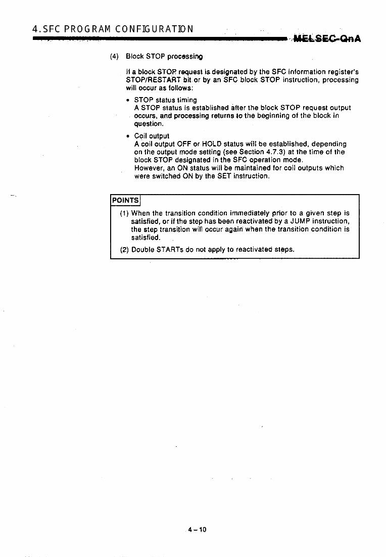
(e) Block STOP processing If a block STOP request is designated by the SFC information register’s STOP/RESTART bit or by an SFC block STOP instruction, the step in question wilt become inactive, with processing occurring as fotlows: 0 Step becomes inactive after the block STOP request occurs,
Q All coil outputs except those which were switched ON by the and processing returns to the beginning of the block.
SET instruction will switch OFF.

An operation HOLD step (without transition check) is a step where Operation output l a m ! , ' p r g o e s s i n g continues men aft,er a transition to the next step. HOW-@, transitm,prwepsing will not be executed when the transition condition-is satisfied again,
(1) During normal SFC programpperation, the coil ON status (switched ON by OUT instruction when transttidh conditMn is satisfied) is automatically switched O F F before proceeding tQ the next step. By designating an operation output step as an "operation HOLD step" (without transition check), that step will remain active even after a transition to the next step occurs,' ahd processing of its operation output ladder wiH continue. Therefore, the coil status will .bel&nged if the input conditions are changed.
(2) As no transition condition check occurs when the next step becomes active, no step transition will occur when the transition conditions for the step in question are again satisfied.
POINT I The difference between an "operaticm HOLD step (without transition check)" and a 'coil HOLD step" is that processing continues even after the step transition with the former, and does not with the latter.
No subsequent transition
9 [ satisfied 1 Step activated by : ..,. '.: v .. previous transition :@$$ji; condition being
(3) An operation HOLD step (without transition check) becomes inactive when any of the following occur:
When the END step of the block in question is executed. When an SFC control instruction (RST BLm) designates a forced
0 When an SFC control instruction (RST BLm\Sn, RSTSn) designates
0 When a reset occurs at the device designated as the SFC informa-
0 When a reset step for resetting the step in question becomes active. 0 When the SFC START/STOP command (SM321) is switched OFF.
END at the block in question.
a reset at the block in question.
tion register's block START/END device.
I 4-9
-. .
4. SFC PROGRAM CONFIGURATION
(4) Block STOP processing
I f a block STOF! request is designated by the SFC information register’s $TOP/RESTART,bi! or by an SFC block STOP instruction, processing will occur as follows:
STOP status timing A STOP status is established after the block STOP request output occurs, and processing returns lo the beginning of the block in question. Coil output A coil output OFF or HOLD status will be established, depending on the output mode setting (see Section 4.7.3) at the time of the block STOP designated in the SFC operation mode. However, an ON status will be maintained for coil outputs which were switched ON by the SET instruction.
(1) When the transition condition immediately prior to a given step is satisfied, or i f the step has been reactivated by a JUMP instruction, the step transition will occur again when the transition condition is satisfied. ,
(2) Double STARTS do not apply to reactivated steps.

4.2.6 Operation HOLD step (with transition check)
An operation HOLD step (with transilion ch,eck) is a step where operation output ladder processing continues even after a transition to the next step, with the next step being reactivated when the transition condition is again satisfied.
(1) During normal SFC program operation, the coil ON status (switched ON by OUT instruction when transition condition is satisfied) is automatically switched OFF before proceeding to the next step. By designating an, operation output step as an "operation HOLD step" (with transition'check), that stepwill remain active even after a transition to the next step occurs, proc.q$sing of' its operation output ladder will continue, and a transition condition check will be executed. If the transition condition is satisfied again, a transition to the next step will occur with that step being activated, while the current step remains active (repeated operation).
'OINTS I (1) A pulse (PLS) format should be used for the transition condition.
If a pulse format is not used, scan transition processing will occur each time a condition is satisfied.
(2) If a double START occurs due to the transition destination step being active when thmansition condition is satisfied, processing will be according to the parameter setting. Refer to Section 4.7.6 for details regarding parameter settings and the processing for each setting.
(3) The difference between operation HOLD steps with and withoU transition checks is as follows: At operation HOLD steps with transition checks, the next step is activated when the transition condition is again satisfied. At operation HOLD steps without transition checks, the next step is not activated when the transition condition is again satisfied.
A (Transition oxwuled again)
4
4-11

4. SFC PROGRAM . . . _ . CONFIGURATION J M E C S G Q n A
(2) An operation HOLD step (with transition check) becomes inactive when any of the following occur:
0 When the END step of the block in question is executed. When an SFC control instruction (RST BLm) designates a forced
When an SFC control instruction (RST BLm\Sn, RST Sn) desig-
When a reset occurs at the device designated as the SFC informa-
When a reset step for resetting the step in question becomes active. When the SFC START/STOP command (SM321) is switched OFF.
END at the block in question.
nates a reset at the block in question.
tion register's block START/END device.
(3) Block STOP processing
If a block STOP request is designated by the SFC information register's STOP/RESTART bit or by an SFC block STOP instruction, processing will occur as follows:
STOP status timing A STOP status is established after the block STOP request output occurs, and processing returns to the beginning of the block in question. Coil output A coil output OFF or HOLD status will be established, depending on the output mode setting (see Section 4.7.3) at the time of the block STOP designated in the SFC operation mode. However, an ON status will be maintained for coil outputs which were switched ON by the SET instruction.
4.2.7 Reset step ml A reset step is a step which designates a forced deactivation of another specified step (operation output).
(1) When the reset step is activated, a specified step within that block will be reset (deactivated). If "999" is designated as the step to be reset, all coil HOLD, operation HOLD (without transition check), and operation HOLD (with transition check) steps within that block will be reset.
(2) In addition to designating the step to be reset (1 step, or all HOLD steps), a reset step possesses the same functions as a normal step (no step attributes).
4-.12

Only HOLD steps can be reset (deactivated) by a reset step. Resets areimpossible for acthe WkU steps where a HOLD status is not in effect, and for steps not designated\ as HOLD steps.
.b ,: -1 , . ,
. .
4-43
4. SFC I .. _.. PROGRAM -,I .,& < . , ~ . CONFIGURATION I
... .--
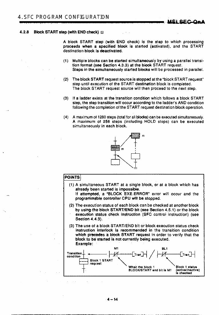
4.2.8 Block START step (with END check) E
A bhck START step (with END check) is the step to which processing proceeds when a specified block is started (activated), and the START destination block is deactivated.
(1) Muttiple blocks can be started simultaneously by using a parallel transi- tion format (see Section 4.3.3) at the blook START request. Steps in the simultaneously started blocks will be processed in parallel.
(2) The block START request source.is stopped at the "block START request'' step until execution of the START destination block is completed. The block START request source will then proceed to the next step.
(3) If a ladder exists at the transition condition which follows a block START step, the step transition will occur a W d i n g to the ladder's AND condition following the completion of the START request destination block operation.
(4) A maximum of 1280 steps (total for all bbcks) can be executed simuttaneously. A maximum of 256 steps (including HOLD steps) can be executed simultaneously in each block.
m
'OMTSI
(1) A simultaneous START at a single block, or at a block which has already been started is impossible. If attempted, a 'BLOCK EXE.ERROR" error will occur and the progremrnable contdler CPU w i l l be stopped.
(2) The execution status of each block can be checked at another block by usin@ the block STARVENO bit (see Section 4.5.1) or the block executhn s?atus check instrdction (SFC control instruction) (see Sett im 4.4.3).
(3) The use of a block START/END bit or block execution status check instruction interlock is recommended in the transition condition which prWe&s a black START request in order to verify that the Mock to b6 started is not currently being executed. Example:
/ & T r a n H
request \ When the block 1 Block 1 status BLOCUSTART end bit is Ml (activellnactive)
Is checked
'4 -14

4.. SfC,eROQRAM CONFIGURATION
4.2.9 Bbck START step (without END check)
A block START step (without END check) is the step to which processing proceeds when a specified block is started (activated), without waiting for the START destination black to be deactivated.
(1) Transition from the block START request source to the next step occurs when the transition condition which foUows the block START step is satistisd. This transition occurs without waiting for the START destina- tion block execution to be completed. Processing of the START destination sub-block continues without inter- ruption.
(2) Multiple blocks can be started simultaneously by using a parallel transi- tion format (see Section 4.3.3) at the block START request. Steps in the simultaneously started blocks will be processed in parallel.
(3) A maximum of 1280 steps (total for all blocks) can be executed simulta- neously. A maximum of 256 steps (including HOLD steps) can be executed simultaneously in each block.
m
'OINTS I (1) A simultaneous START at a single sub-block, or at a sub-block
which has already been started is impossible. If attempted, a 'BLOCK EXE.ERROR" error will occur and the programmable controller CPU will be stopped.
(2) The execution status of each Mock can be checked at another block by using the block START/END bit (see Section 4.5.1) or the block execution status check instructioq (SFC control instruction) (see Section 4.4.3).
(3) The use of a block START/END bit or block execution status check instruction interlock is recommpnded. in the transition condition which precedes a block START request in order to verify that the block to be started is not currently being executed.
M1 BL1 Transition condition W T r a n I / *-[Trany
&=ART \ 2 request \ \
When the block 1 BLoCWSTART end bit is M1 (activelinactive)
Block 1 status
is checked
4- t 5

4. SFC PROGRAM CONFIGURATION 'h4BabsGW
4.2.10 B W END
(1) A "block END" indicates the end of the processing sequence for a given block.
(2) After a block END execution is completed, operation is restarted by the methods shown below.
Block No. Reslart Mothod
I When block 0 START condition is designated as auto 'START ON' I
At block 0 at ttG SFC parameter setting. When block 0 START condition is designated as 'auto START O F F at the S F C parameter setting.
Processing automatically returns to the initial step and operation is repeated.
A restart is executed when any of the following occurs: (1) When another START request is received from another
(2) When the block START Instruction ( S F C control instruction) I (3) When the block information register's block STARTlEND bit
block(block START step is activated).
is executed.
is forced ON. At all other blocks (other than block 0 )
4-16

4.3 Transition Condition ~ ~ * . ,. , . , . ,
. . A 'ttansition conditkn" is the condition which must be satisfied in order for processing to proceed to the next step.
"Serial transition" is the transition format in which processing proceeds to the step. immediately below the current step when the transition .ccmdition is satisfied.
Step .n* (operation output [A])
Transltlon condition 'b'
Step 'n+l' (operation output [e])
When transition condition 'b' becomes satisfied at step 'n' (operation output [A]) execution, operation output [A] will be deaclivated,'and prcwsbing wHl proceed to step 'n+l' (operation output p H . -
-
Max. of 1536 lines
-
(1) A -maximum of 512 serial transition steps (a 0 ) per block are possible, representing 51 2 serial transitions (+). However, the number of lines is restricted according to the SFC display column setting, as shown below.
When SFC display column setting is '1' or '2'
- -
Max. of 51 2 serial transition:
- -
O Examples of the permissible number of lines corresponding to a few SFC display column setting values are shown below. The SFC dis-
lay column setting value can be designated P reely within a 1 to 32 range.
of lines Number
I
t
Number of columns (max. of 32) * b
Number of lines s Approx. 3000 SFC display column setting value (n)
8FC D1apl.y Cob umn aettlng
Number of Llnes Poaalble
112 32 28 22 16 8
1536 96 108 138 192 384
4-17

4. SFC I. <_ PROGRAM - _I . ,. , . .* ._ CONFIGURATION ..&u!&&wQJ&A (2) Serial transition operation flowchart
Step 1
Transition condition 'b'
Step 2
condition 'c'
Step 3
R Transition condition 'd" - END step
c Operation status 1 1 ' 1
Initial step operation 1 I
1 Transition condition 'a' satisfi
lnltial step operation output deactivated.
1 Step 1 operation output executed. 1
fi Transition condition 'b' satisfied?
1 YES .1
1 Step 1 operation output deactivated. 1
)LJ Transition condition .c' sptisfi
1 YES .1
I Step 2 operation output deactivated. I
I 1
I Transition condition 'dm satisfied
comokted.
'1 For steps with attribute designations, processing occurs in accordance with the attributes.
4-18
4.3.2 Selection transition
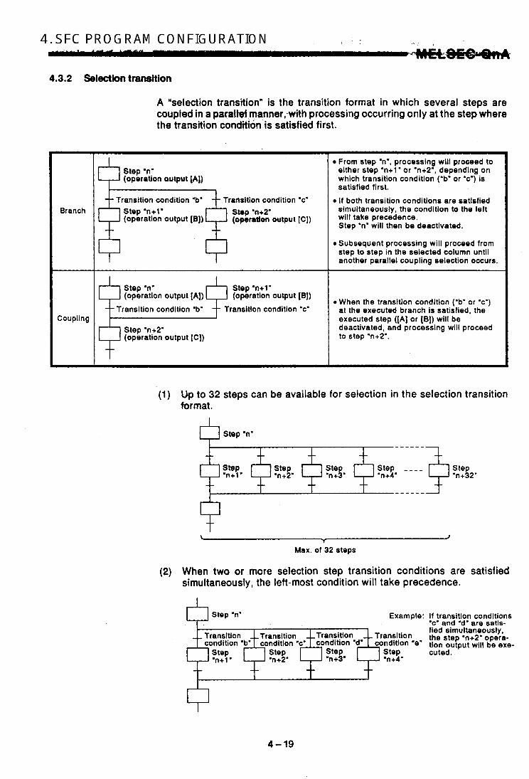
A "selection transition" is the transition format in which several steps are coupled in a paralWmanner,-with processing occurring only at the step where the transition conditbn is satisfied first.
Branch
Step 'n' (operation output [A])
-- Transition condition 'b' ransition condition 'c' Step 'n+l' Stop 'n+2' (operation output [e)) (operation output [C])
I
, Coupling
Step 'n' (operation output [A])
Step 'n+l' (operation output [BJ)
Transition condition 'b' condition 'c'
Step 'n+2' (operatlon output [C])
From step 'n., processing will proceed to either step 'n+l' or 'n+2', depending on which transition condition (.bg or V ) is satisfied first. i f both transition conditions are satisfied simultaneously, the condition to the left will take precedence. Step .ng will then be deactivated.
Subsequent processing wiii proceed from step to step in the selected column until another parallel coupling selection occurs.
When the transition condition (.b* or 'c') at the executed branch is satisfied, the executed step ([A] or [B]) will be deactivated, and processing will proceed to step 'n+2'.
(1) Up to 32 steps can be available for selection in the selection transition format.
Step .n'
+ + + + + L + +
J T
Max. of 32 steps
(2) When two or more selection step transition conditions are satisfied simultaneously, the left-most condition will take precedence.
Step 'n' Example: If transition conditions 'c' and 'd' are satia-
ransition the step .n+2' opera- fied simultaneously,
ndltion '8' tion output will be axe- Step cuted. 'n+4'
n v
4-19

4. SFC PROGRAM CONFIGURATION . .ELSEGWA
(3) The following method of coupling can be omitted when the selection transition format is used.
Q Step 'n'
Transition conditlon 'c'
+step
'n+5'
When transition condition "b" is sa- tisfied at the step "n" operation out- put, processing will proceed in order through steps "n+l", "n+2" and "n+3". When transition condi- tion 'd" is satisfied, processing will jump to step "n". (For details on "jump transitions", see Section 4.3.4.)

(4) Selection transitlan operatian flowchart
Operation status
condition 'd' condition '0'
YES
I Step 1 operation output
doactivatd. deactivated. Fco- 'h' utislied? ~~3 Step 4 operation output , [ step 2 operation output executed. t- 1 V -
Stop 6 operation output
St- 4 owration output
A deadivated.
Tranaition .j. satislid? condition St- 5 operation output st,,&-t-,
Stop 6 op.ration output deactivated. Transition condYion . - sathhd?
Transition condition 'd' satidiad?
Stop 6 operation output Step 3 operation output deactivated.
Stap 7 operation output
doactivrtod.
'1 For steps with attribute designations, processing occurs in accordance with the attributes.
4-21
4. S,FC PROGt%AM CONFIGURATION - 4.3.3 PeFPllel tmrWbn
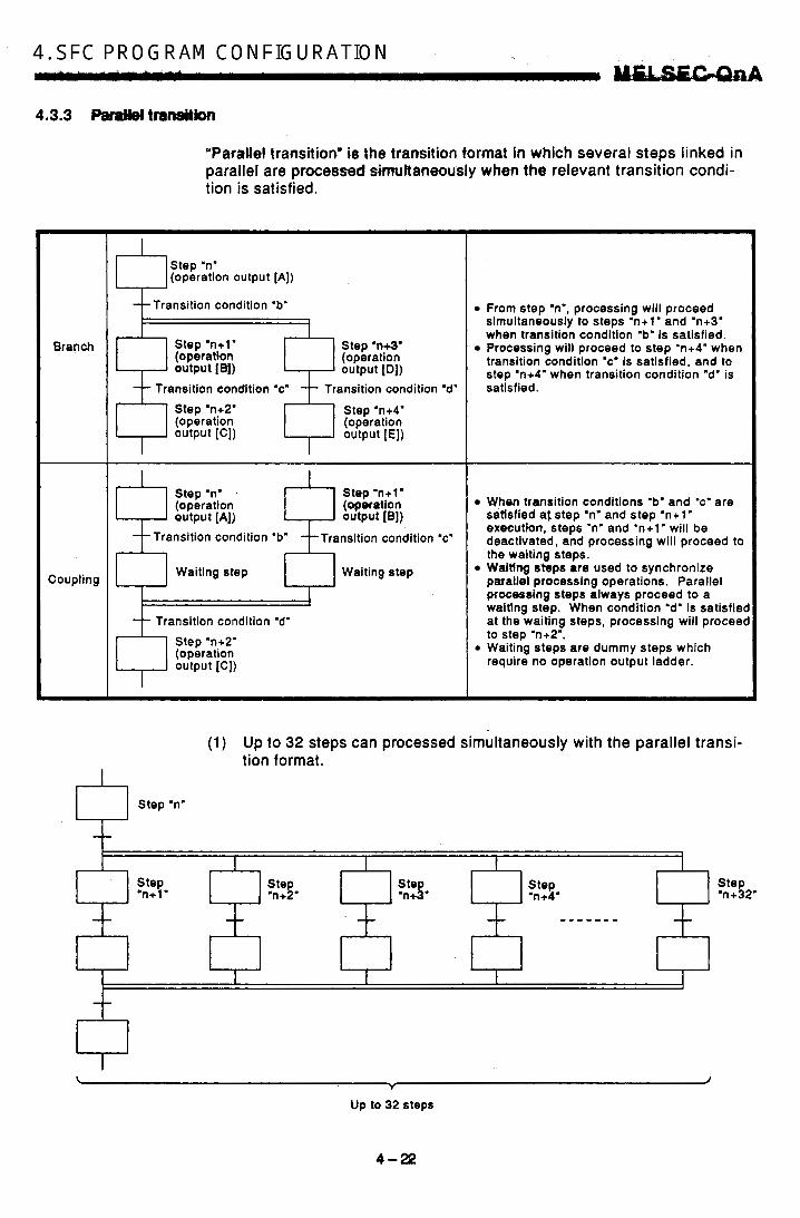
'Parallel transition* is the transition format in which several steps linked in parallel are processed simukaneously when the relevant transition condi- tion is satisfied.
Branch
Coupling
I
I
Step 'n' (operation output [A])
--Transition condition 'b"
Step 'n+l' (operation 1 ' 1 Step 'M' output [el)
(operation output [Dl)
Transition condltion 'c' Transition condition 'd' Slep 'n+2' (operation I Step 'n+4'
(operation output [E]) output [C])
I I Step .no Step 'n+l' (operation output [A])
(qeration output [B])
Transition condition 'b' Transition condition 'c'
I Waiting step Waiting step
I -- Transition condition 'd'
/ , I Step 'n+2' (operatlon output [C])
From step .ng, processing will proceed simultaneously to steps 'n+l' and 'n+3' when transition condition 'b" is satisfied. Processing will proceed to step 'n+4" when transition condition 'c. is satisfied, and to step 'n+4' when transition condition 'd' is satisfied.
When transition conditions 'b' and 'c' are satisfied a t step .n' and step 'n+l' execution, steps 'n' and 'n+l' will b e deactivated, and processing will proceed to the waiting steps. Waiting steps are used to synchronize parallel processing operations. Parallel processing steps always proceed to a waitlng step. When condition 'd' is satisfied at the waiting steps, processing will proceed to step 'n+2'. Waiting steps are dummy steps which require no operation output ladder.
(1) Up to 32 steps can processed simultaneously with the parallel transi- tion format.
I
I
Step 'n'
--
Step 'n+ 1.
Ste an + L '
T
Up to 32 steps
4-2e

g d
(2) If another block is started by the parallel processin$ ope#u&ifbv the START source block and START destination block will be executed si- multaneously. (In the example below, processing from step 'n+l" will be executed. simubnewsly withblock 1 .) Block 0
Step 'n" Transition
0 Step 'n+l' Block 1 START
t condition , Transition Transition condition t When condition "b" is satisfied at
! step "n" execution, Drocessina will I I
proceed to step "n+l" and block 1 wiU be started. Blocks "0" and "1" will then be processed simultane- ously.
t (3) Up to 1280 steps (total for all blocks) can be processed simultane-
ously. If the 1280 limit is exceeded, an error will occur and the PC CPV operation will be stopped. The maximum number of active steps per block is 256.
(4) Couplings must be provided when the parallel transition format is used. Program creation is impossible without couplings. Example: Program without couplings (NG example)
90 t t
e' W' 1
Jump
Each column ends & END step at the END step.
Jump transition (see Section 4.3.4) occurs without coupling - 4
(5) As a rule, a waiting step must be created prior to the coupling. However, in cases such as the example below where each of the par- allel transition columns consist of only 1 step (program without a tran- sition condition between the parallel transition branch and the coupling), a waiting step is not required.
t
4- 23

4. SFC PROGRAM CONFIGURATION . : U E - c t Q a A
(6) Parallel transition operation flowchart
Parallel procowing
Operation rtatur 1
Initial atop operation output
.X.cutd.
I d " " ' r " d . I Step 1 operation output
Step 2 operation output ex.cutd.
Step 3 operation output Step 4 operation output
1 YES
I deactivated. I 1 d e a c t F t d . I L deadvatd . I Step 2 operation output Step 3 operation output Step 4 operation output
c I I
'1 For steps with attribute designations, processing occurs in accordance with the attributes.
4-24
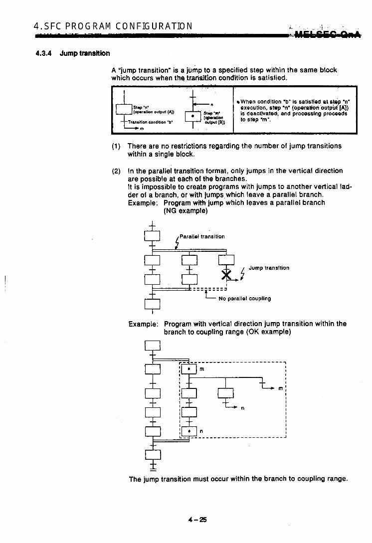
4.3.4 Jump transition
A "jump transition" is a jump to a specified step within the same block which occurs when the trm-si€ion condltion is satisfied.
When condition 'b' is satisfied at spp :n' execution, step h' (operabion otttput'fAf) is deacthrated, and processing proceeds (-ration output [A])
tcoic.tion to m.. Tramition condition 'b' 0;tPul PI)
.!
(1) There are no restrictions regqrding the number of jump transitions within a single block.
(2) In the parallei transition format, only jumps in the vertical direction are possible at each of the branches. It is impossible to create programs with jumps to another vertical lad- der of a branch, or with jumps,which leave a parallel branch. A, ~
Example: Program with jump which leaves a parallel branch 4 v
(NG example)
Paralid transition
8 8 2 j Jump transition
Example: Program with vertical direction jump transition within the branch to coupling range (OK example)
1 --1
I 1 I I I
' m : I I I I I I I
- The jump transition must occur within the branch to coupling range.
I
Y
4-25
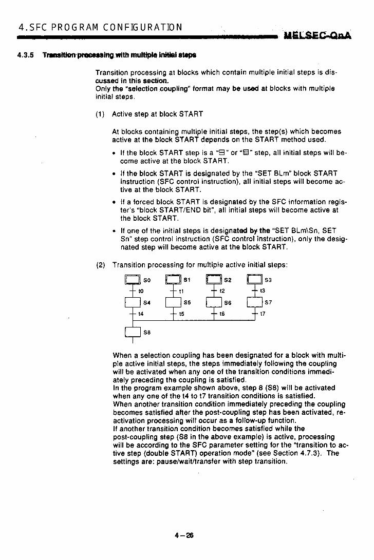
. .=-
4. SFC. P,ROGRAM . 7 1 CONFIGURATION u-
Transition processing at blocks which contain multiple initial steps is dis- cussed in this sedan. Only h e ’selection coupling” format may be used at blocks with multiple initial steps.
Active step at block START
At blocks containing multiple initial steps, the step(s) which becomes active at the block START depends on the START method used.
0 If the block START step is a “E” or “€I” step, all initial steps will be-
If the block START is designated by the “SET BLm” block START come active at the block START.
instruction (SFC control instruction), all initial steps will become ac- tive at the block START. If a forced block START is designated by the SFC information regis- ter’s “block START/END bit”, all initial steps will become active at the block START.
0 If one of the initial steps is designated by the “SET BLm\Sn, SET Sn” step control instruction (SFC controt instruction), only the desig- nated step will become active at the block START.
Transition processing for multiple active initial steps:
-- t4
S8
When a selection coupling has been designated for a block with multi- ple active initial steps, the steps immediately following the coupling will be activated when any one of the transition conditions immedi- ately preceding the coupling is satisfied. In the program example shown above, step 8 (S8) will be activated when any one of the 14 to 17 transition conditions is satisfied. When another transition condition immediately preceding the coupling becomes satisfied after the post-coupling step has been activated, re- activation processing will occur as a follow-up function. If another transition condition becomes satisfied while the post-coupling step (S8 in the above example) is active, processing will be according to the SFC parameter setting for the “tansition to ac- tive step (double START) operation mode” (see Section 4.7.3). The settings are: pause/wait/transfer with step transition.

4.3.6 Recautions when creating sequence pmgmms W.oP#rcbn wtpute(~)and' tmmRion conditions
The points to consider when creatingwea!ion output (step) and transition cond#kn sequence programs are desdribed below.
(1) Sequence program for operation outputs (steps)
(a) Step sequence program expression format A step sequence program using the ladder expression format is shown below.
Condition u n b. omiltd only at the lint ladder b i d
Condition instruction
4
h
v
The lack of a sequence program at a glven step will not result in an error. In such cases, no processing will occur until the transition condition immediately following the step in question is satisfied.
(b) Sequence program capacity A step's sequence program capacity is as follows: 0 Max. of 4K sequence steps per step. 0 Max. of 4K sequence steps per block.
4- 27
1
t

4. SFC , . PROGRAM ..y >.' .., CONFIGURATION r L r = l _ s s ; . c i a a A
Class
Master control
END
Program branch
Structuring
Debugging failure diagnosis
SFC dedicated instructions
- . I
(c) instructions used All instructions except for those shown below may be used.
Prohibited Instruction List Insirucilon
Code Symbol Remarks Funstlon
MC
Sequence program END END END
Main routine program END FEND FEND
Master control reset MCR N u MC R
Master control set MC N O No.1-D
,C J I C J P O I Condition jump I _. . - ~.
SCJ Delay jump SCJ P a Use of label 'P' is also prohibited
JMP
Relative jump RCJ (S) RCJ
Unconditional jump JMP P a
ACJ
Jump to END GOEND GOEND
Absolute jump ACJ (S)
IRET Reset from interrupt program R E T Use of label 'I' Is afsb pkohtblted
BREAK I BREAK (D) po I Forced END to repeat operation I ~ ~ ~~~~~
RET
Begin check pattern change CHKCIR CHKCiR
Prescribed format failure check CHK CHK
CHK Instruction START CHKST CHKST
Reset from subroutine RET
CHKEND
SFC program END SFCPENO SFCPEND
SFC program START SFCP SFCP
End check pattern change CHKEND
~ -~ -~
BLOCK
STEP? (S) STEP?
SFC block END BEND BEND
SFC block START BLOCK (S)
= N, D, SC, SE, ST, R, C, G, I , ID, ISC, ISE, IST, IR
TRAN? 1 TRAN? (S)
= L, 0, OA, OC, OCA, SFC hansition START [ ? A, C, CA, CO, COC
TAN D
TSET (S) TS ET
SFC coupling check TAND (S)
Designate SFC transition destlnation
SEND I SEND I SFC step END I

(2) Sequence program for 2ranshiwl condition
(a) Transition condition sequence program expression format 1 <,! 1 " " , : : , .-:. ,-: ,-: '
A t-sequenaevgram ushrgttrstadderrexpresslon format is shown Below. 7 ,rT+ TmW - is dunmy output
(b) Sequend&'firOgram capacity A transitl0iycgnUition's sequence program capacity is as follows: 0 Max..'tif 4K dequence steps per transition condition. 0 M a x . trf dK;sequence steps per block.
(c) Instructlbir's used Instructions which can be used in a transition condition sequence program . . are listed below.
.- .
CI.88 Inatructlon Code Symbol Function Remarks
LD
L--l+ OR ++ AND
Operation START (NIO contact) H+ Serial connection (NK, contact) Parallel connection (NIO contact)
Contacts Operation START (NIC contact) Serial connection (NIC contact) Parallel connection (NIC contact)
LD P ANDP
H t
Leading edge pulse parallel connection w t + ORP
LDF H 1 E Trailing edge pulse operation START
ANOF -4 ORF
Trailing edge pulse serial connection
ANB Ladder block serial connection ORB Ladder block paratlei connection
INV - Operation result Inverbion
Leading edge pulse operation START f 1 Leading edge pulse serial connection
Contacts
-I+ Trailing edge pulse parallel connection
Coupling MEP MEF
-t- Operation results converted to leading edge pulse (step memory)
pulse (step memory) Operation results converted to leading edge
EGP pulse (memory) EGF --lV -'% Operation results converted to trailing edge
Dulse Imemorv)
- i- Operation results converted to trailing edge
4-29
h W

c-
4. SFC PROG,RAM - . CONFIGURATION 1 , M s u x c a A
Class
Comparison operation
Contacts (program operation status check)
lnstruetlon Code
LD 0 ANDO OR 0
LDD 0 ANDDU ORDO
LDEU ANDEO OREO
LDS 0 AND$ 0 OR$ 0
LDPCH.K ANOPCHK ORPCHK
Symbol
LD 0 A N D O (S l ) (SO) OR 0 0 (=, <>, >, >=, <, <I)
LDD 0 ANDDO (SI) (s2) ORDO O(-, <>. >, >=, <, <=)
LDE 0 ANDEO (SI) (s2) ORE 0 0 (=, <>, >, >=, <, <=)
L D $ O ANDSO (SI) (s2)
0 (I, <>, >, >=, <, <=) O R s 0
H C H e 4 C H e (s) W C H V
Function
BIN16 bit data comparison
BIN32 bit data comparison
I Floating decimal point data comparison
Character string data comparison
Operation START (NIO contact) Serial connectlon (NIO contact) Parallel connection (NIO contact)

4.4 Controlling SFC Programs by Instructions (SFC Control Instructions)
SFC control instructions can be used to check a block or step operation status (active/inactive), or to execute a forced START or END, etc. They can be used in SFC programs for easier SFC program control. The various S f C control instructions and their functions are shown in the table below.
Name I bddu Ixpreraton I Funcllon
Step operation status check nstructionO
[ LDI, ANI, OR1 ] Sn LD, AND, OR, '1 Checks a specified step in a
specified block to determine I f the step is active or inactive.
LDI. ANI. OR1
Forced transition check Instruction
Block operation status check [ LD, AND, OR.] BLm instruction LDI, ANI, OR1
Checks a specified step in a specified block to determine if the transition condition (by transition control instruction) for that step was satisfied forclbly or not.
~~~~ ~ ~ ~~~ ~ ~
Checks a specified block to determine i f i t is actlve or inactive.
MOV( P) BLm\K4Sn (0) Active steps in a specified block
Active steps batch readout instruction are read to a specified device as DMOWP) BLm\KBSn (Dl bit information.
BMOV(P) K4Sn ( 0 ) Kn '1 BMOV(P) BLmu(4Sn (D) Kn
Block START instruction (activated) independently and is SET BLm A specified block is forcibly started
executed from its initial step.
Block END instruction RST BLm A specified block is forcibly ended (deactivated).
Block STOP instruction PAUSE BLm A specified block is temporarily stopped.
Block restart instruction RSTART B Lm
SET Sn '1
SET BLm\Sn
Step control instruction
The temporary stop status at a specified block is canceled, with operation resuming from the STOP step. A specified block is forcibly started (activated) independently and is executed from a specified step.
RST Sn '1 RST BLm\Sn
A specified step at a specified block is forcibly deactivated.
The instruction execution step is SCHG (Dl '2
SET BLm\TRn A specified transition condition at a SET TRmn '1
deactivated, and a specified step is
specified block is forcibly satisfied.
RST TRn '1 The forced transition at a specified
RST BLm\TRn
activated.
Transition control Instruction
transition condition in a specified block is canceled.
Block switching Instruction BRSET (SI Blocks subject to the "1' SFC control instruction are designated.
4-31

4. SFC PROGRAM CONFIGURATION . r l I Z l -
Name
Subroutine call instruction
Program operatlon status check in- slructlon
Time check instruction
Ladder Expresston Function
Whon the instruction execution condition is ON, the subroutine call is executed in a constant manner. When it is switched OFF, the subroutine call occurs only once at that time.
XCALL Pn
(LD, AND, OR) PCHK 'Program name' specified program is being A check occurs to determine i f a
executed. When the designated time period beginning from the point when a
TiMCHK (S I ) (S2) (Dl spedfied condition is satisfied elapses, the designated output device is switched ON.
'1: The block designated by the block switching Instruction (BRSET) becomes subject to the instruction. (The default setting is 'block 0' or 'all blocks') ... see Section 4.4.1 1
'2: Use is permitted only at steps with SFC programs. An error will occur if used at steps with other sequenoe programs.
4-92


4. _, SFC ,- . , PROGRAM L / . , .., CONFIGURATION
Internal (Syrtem, Uror) vlce 1 Bit
I FX, FY, S, SM. X. Y.
Word
A , VD, SD, T, C, D, W, SW, FD, ST
T NET/lO Direct Sp8Cld Function Indox
R Module 2 0 Constant Other
uO\aO I J n\X J o \ Y J n\B J O\SB
J o\W J o \ S W
U n\G z Decimal P, I , hexadecimal J, U, real number . DX, constant DY, character string N, BL, constant TR,
BL\S
When a device name is indicated in the 'constant", "expaaon SFC", or the "other" column, only that device may be used. Example: If "K,H" is indicated in the "constant" column, only a decimal (K) or hexadecimal (H) constant may be used. Real number constants (E) and character string constants ($) may not be used.
(3) ... The data type for the designated device is indicated here. Bit. . . . . . . . . . . . . . . . Indicates a bit data
operation.
value processing. 1 word used.
value processing. 2 words used.
string processing. Variable number of words.
first device processing. Variable number of words.
. BIN16 . . . . . . . . . . . . Indicates 16-bit binary
BIN32 . . . . . . . . . . . . Indicates 16-bit binary
Character string. . . . Indicates character
Device Indicates. . . . device name and
(4) ... The type of program which can be used with the instruction in question is indicated here.
here. (5) ... The request destination for the instruction in question is indicated
4-34

4.4.1 Step opercrdion status check instwtions (LO, LDI, AND, ANI, OR, ORI)
l o 1 I
D.* T l P
Device name
(') Sn only At 'expansion SFC' and 'other' columns, 'm' represents the block No., and On' represents the stepltransition condition No..
LD BLrn\Sn 1 BLm\Sn
LDI BLrnBn 1
Function ,-
( I ) Checks a specified step in a specified.Mock to determine if the step is + active or inactive.
(2) If the step in qcestion is active, the N/O contati instruction switches the contact ON, and the N/C contact instruction switches the contact OFF.
(3) To designate a step in the current block, use 'SN". To designate a step in another block, or to execute an instruction by the sequence program, use 'BLm\Sn".
(4) If the step in question does not exist in the SFC program, it will remain OFF.
4-35

..A.
Program Examples (1)
(2)
The following program switches Y20 ON when !he operation status of step 5 in block 3 is checked, and found to be active.
F Designating a step within the current block
Designating a step In another block
BL3S5
The following program executes a step synchronously with another step of a parallel branch.
'lo 520 Interlock
t t $ 1 s20
I Related Instructions I
t I-'
a) SFC control instructions 0 Block switching instruction (BRSET) . . . . See Section 4.4.1 1. 0 Step control instruction (SCHG) . . . . . . . . See Section 4.4.10. 0 Active step batch readout instruction
(MOV(P), DMOV(P), RMOV(P)). . . . . . . . . See Section 4.4.4.

I u d b Mea 1
At 'expansion SFC' and 'other' columns, 'm' represents the block No., and 'n' represents the step/tramition condition No..
!-TRn%- 'nu it tho trantlion condition No. -
LO TRn e-lA TRn
.OI TRn 7
\NI TRn -- 3RI TRn
ANI BLm\TRn 1
OR1 BLm\TRn
Function (1) A check occurs to determine if a forced transition is designated for a specified transition condition in a specified block.
(2) If a forced transition is designated at the transition condition in question, the N/O contact instruction switches the contact ON, and the N/C contact instruction switches the cyntact OFF.
To designate a step in another block, or to execute an instruction by the sequence program, use "BLm\TRn".
(3) To designate a step in the current block, use 'TRn".
f
i
(4) If the transition condition in question does not exist in the SFC program, it will remain OFF.
4-37
i

4. SFC . . PROGRAM ~ 1 I... CONFIGURATION hkklSEC-QnA Program Examples (1) The following program switches Y20 ON when a f o r c e d , trmsition is
designated for transition condition 5 at block 3. I Designating a transition condition No. within the c u r r e n t block I
I Designating a transition condition No. in another block I
See Section 4.4.9. See Section 4.4.1 1.
(Related Instructions1 a) SFC control instructions
Transition control instructions (SET TRn, SET BLm\TRn, RST TRn, RST BLm\TRn) . . .
0 Block switching instruction (BRSET)
4-38
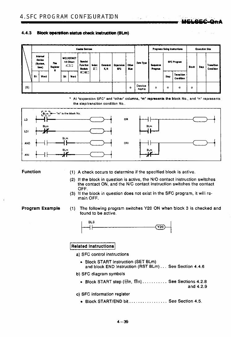
O I o I O I o ( I At 'expansion SFC' and 'other' columns, 'm' repmsents the block No., and 'n' represents the stepltransition condition No..
LD I
Function (1) A check occurs to determine if the specified block is active. (2) If the block in question is active, the N/O contact instruction switches
the contact ON, and the N/C contact instruction switches the contact OFF.
(3) If the block in question does not exist in the SFC program, it will re- main OFF.
Program Example (1) The following program switches Y20 ON when block 3 is checked and found to be active.
I Related Instructions1 a) SFC control instructions
0 Block START instruction (SET BLm) and block END instruction (RST BLm) . . . See Section 4.4.6
b) SFC diagram symbols
0 Block START step (En, €In). . . . . . . . . . . See Sections 4.2.8 and 4.2.9
c) SFC information register Block STARTEND bit.. . . . . . . . . . . . . . . . See Section 4.5.
f V
4-39

4. SFC " . _ , PROGRAM , . L , , CONFIGURATION UELSEGQ~A 4.4.4 Active step betch teadout instructions (MOV, DWV)
I I I I I
Bit W a d Bit W a d
I I I I
(S)
(D) 0
(*I 0 BtN16/ - BIN32
(*) Sn only At 'expansion SFC' and 'other' columns, "m' represents the block No., and 'n' represents the stepltransition condition No..
Function (1) Executes a batch readout of the operation statuses (active/inactive) of steps in a specified block.
(2) The readout results are stored at the "D" device as shown below. b15 b l 4 b13 b12 b l l b10 b9 b8 b7 b6 b5 M b3 b2 b l bo _ . ~ ~~ ~~ ~ . . ~
011 011 011 ot1 011 011 011 011 011 011 011 011 011 011 011 011 b b b
I Step designated at Sn
Sn + step 15 Sn + step 1 0: Step in question is inactive
(3) .If the steps in question do not exist in the SFC program, they will remain OFF.

Program Examples (1) The following program MI read out steps 0 to 32 if! M a 3 when X0 switches ON.
I Dw)anatina a step within the current block I
Designating a step in another block 1 L 1
bt5 b14 b13 b12 bll b10 bQ b8 b7 b6 b5 b4 b3 b2 bl bo
Dl Step Nos.
r31 .30 r2Q r28 r27 r26 a25 624 823 rZ? 821 820 r l 9 sl8 r17 r16
I Related Instructions I a) SFC control instructions
~ ~~~ ~~
0 Block switching instruction (BRSET) . . . . See Section 4.4.1 1. Step operation status check instruction (Sn) ...................... See Section 4.4.1.
0 Active step batch readout instruction (BMOV) . . . . . . . . . . . . . . . . . . . See Section 4.4.5.
I
1
v
4 -41 k
.

4. SFC PROGRAM 'i a, CONFIGURATION U' - - UIELSEC-UaA 4.4.5 Active step batch readout (BMOV)
Inbmrl
Rqbtu
811 W a d
hCX 2: :
I I I
I I ( W 0
h w U k g lhftuctlon twuon Sib
S q U U l C +
Program
SFC Propram Tramition Condition Block 'W
Tnnltion Cmdltlon o.p
0 0 0
h w U k g lhftuctlon twuon Sib
S q U U l C +
Program
SFC Propram Tramition Condition Block 'W
o.p Cmdltlon Tnnltion
(*): Sn only
*: At "expansion SFC" and "other" columns, "m" represents the block No., and "n" represents the .4
stepMansition condition No..
Function (1) A batch readout (designated number of words) of step operation statu- ses is executed at the specified block.
(2) The readout results are stored at the "D" device as shown below. b15 b14 b13 b12 bll b10 b9 b8 b7 b6 b5 b4 b3 b2 bl bo
b b b
Sn +step 15 Sn + step 1 0: Step in question is inactive 1: Slop in question is active
I Sn +31 I I I I I
Sn + 16
Sn + (A x 16 + 15) Sn + (A x 16)
(3) I f the steps in question do not exist in the SFC program, they will remain OFF.
4-42

. . . . . . . . . .
Program Examples (1) When X0 switches ON, the followin&progtam eKecu€es.a9=wacd.read- out (beginning from DO) of block 3 active step statuses.
Do
D l
D2
1 Designating a step within the current block]
BMOVP I K450 I DO I K3
I
F Designating a step in another block
BMOVP 1 BL3SO I DO [ K3
b15 b14 b13 b12 b l l b10 bo b8 b7 b6 b5 b4 b3 b2 b l bo
s15 s14 s13 s12 111 s10 s9 s8 s7 s6 s5 s4 s3 s2 s1 SO \
I l l l l l l l l l l l l l l l I> Step Nos. $31 330 sa s28 $27 s26 $25 324 e23 a22 s21 e20 319 318 s17 s16- /
s47 r48 r45 844 s43 t42 s41 c40 s39 s38 s37 s36 135 r34 s33 132 '
I Related Instructions]
a) SFC control instructions 0 Block switching instruction (BRSET) . . . . See Section 4.4.1 1 0 Step operation status check
0 Active step batch readout instruction (Sn) . . . . . . . . . . . . See Section 4.4.1
instruction (MOD, DMOV). . . . . . . . . . . . . . See Section 4.4.4
4-43
,
i
.

4. SFC ,. r . PROGRAM . CONFIGURATION #ELSE.C-QnA 4.4.6 Bkck START & END instructions (SET, RST)
At ‘expansion SFC’ and ‘other’ columns, ‘m’ represents the block No., and ‘n‘ represents the stepltransition condition No..
Function
Operation Error
Program Examples
7 1 a) A specified block is independently activated forcibly, and is exe-
cuted from its initial step. If multiple initial steps exist, all the ini- tial steps will become active. If the SFC information register “block START/END bit” setting has been designated, the bit device in question will be switched ON.
b) If the specified block is already active when this instruction is exe- cuted, the instruction will be ignored (equivalent to the NOP in- struction), and processing will continue.
p57G- I a) If the SFC information register “block START/END bit” setting has
been designated, the bit device in question will be switched ON.
b) If the specified block is inactive when this instruction is executed, nothing will change.
Error No. 4621 occurs when the specified block does not exist.
When X1 switches ON, the following program forcibly activates block 1. When X2 switches ON, it ends and forcibly deactivates block 1.

I Related Instructions1 1
a) SFC diagram symbols . 1 1 ,
0 Block START step (E, €I) . . . See Sections 4.2.8 and 4.2.9. b) SFC information register
0 Block START/END bit. . . . . . . See Section 4.5.1.

AM CONFIGURATION UELSEC-EQaA
4.4.7 Block STOP & RESTART instructions (PAUSE, RSTART)
At 'expansion SFC' and 'other' columns, 'ma represents the block No., and 'n" represents the step/transition condition No..
I r 'rn' h the block No. I
Function (1) pxiEq a) Executes a temporary stop at the specified block. b) As shown below, processing varies, depending on when the stop
occurs and on the coil output status setting (designated by OUT instruction).
output Status of Mode 5.1- t lng at Pa- Uode'8
rameter Speclal Block STOP
(SM325)
output
ROl8y
Operatlon Descrlptlon Status of I
Block STOP Mode Bit Active Step Other than HOLD Actlve HOLD Step strp
I
After the STOP request, the coil output will be switched OFF the first time processtng occurs at the specified block, and a STOP will occur.
output will be switched OFF when the transitlon condition Is satisfied, and a STOP will occur. If multiple steps are active, the STOP will occur at each of the steps in sequence as their transition conditions are satisfied.
After the STOP request, the coil Coil output OFF,
HOLD coil output
'OFF', or no setting
(immediate stop)
OFF (coil output OFF)
After the STOP request, the coil output will be switched OFF the first time processing occurs at the specified block, and a STOP will occur.
a o ~ ~ ~ ~ l ~ ~ no (immediate
After the STOP request, a c d l output HOLD status will be established the first time processing OCCUrS at the specified block,
stop) and a STOP will occur.
I I I After the STOP reauest. the coil I Coil output
HOLD ON (coil
output HOLD) output HOLD status will be established when the transition condition is satisfied, and a STOP will occur. I f multiple steps are active, the STOP will occur at each of the
After the STOP request, a coil output HOLD status will be established the first time processing occurs at the specified block, and a STOP will occur.
ON (post- transition
STOP)
steps in sequence as their transition conditions are satisfied.
~~~~ .
4-46

CONFIGURATION .. I,
POINTS] (1) The coil HOLD step becomes inactive the first time processing
occurs at tfi-eblock in'quesfion following the STOP requesf.' (2) During SFC program execution, the M325 special relay is switched
OFF when the coil output is OFF, and is switchedON when the coil output is O N , in accordance with the parameter setting. The M325 special relay can also be switched ON and OFF by the user program without regard to the parameter setting.
c) The STOP/RESTART bit switches ON when the SFC control "block STOP" i h h c t i o n (PAUSE BLm) is executed.
a) The block in question is restarted from the step where a STOP oc- curred. An "operation HOLD status" step (with transition check or without transition check) which has been stopped will be restarted with the operation HOLD status in effect. A "coil output HOLD" step cannot be restarted after being stopped as it becomes deactivated at that time.
b) Execution of PLS and P instructions after a block STOP has been canceled varies according to the ON (HOLD) or OFF (all OFF) status of the SM325 special relay (ON: operation output HOLD at block STOP; OFF: all OFF).
SM325 { ON : Not executed OFF : Executed again
c) I f the block restart instruction (RSTART BLm) is executed while the block is stopped, the block STOPIRESTART bit switches OFF.
Operatlon Error Error No. 4621 occurs when the specified block does not exist.
Program Examples (1) Block 1 is stopped when X1 switches ON, and is restarted when X2 switches ON.
I Related hstructions I a) SFC information register
0 Block STOP/RESTART bit ... See Section 4.5.3.
c
4 -47 I i *

4. SFC PROGRAM , ....- CONFIGURATION . - MEESEGQnA
4.4.8 Step START & END instructions (SET, RST)
Function (1) lsETl a) A specified step at a specified block is activated forcibly.
Operation at the block in question varies as follows, depending on whether the block is active or inactive. 0 When the specified block is inactive:
The specified block is activated when the SET instruction is exe- cuted, and processing begins from the specified step. If an SFC information register "block START/END bit" setting has been designated, the bit device in question will switch ON at this time.
If the step is already active when the SET instruction is exe- cuted, the step will remain active and processing will continue, with another step being designated as active. (Multiple step acti- vation, follow-up function.)
When the specified block is active:
b) When multiple initial steps exist, an initial step selection START will occur when a given step is specified and activated.
c) When designating a step located in a parallel branch, all the paral- lel steps should be activated. An inactive parallel branch ladder at such a time will prevent the parallel coupling condition from being satisfied.
d) If a specified step is already active when this instruction is exe- cuted, the instruction will be ignored (equivalent to the NOP in- struction), and processing will continue.

-a) A.qxtcifiedstap. a t . aspacifisd . h l ~ c k ~ i b ~ ~ d ~ ~ ~ ,'CoiL HOLb" and *operation HOLD" steps are subject to this instruction.
b) When the number of active steps at the block in:question -aches "0" dye t9,the execuJion of this RST instructh', bock ENDproces- sing wili ocaw;.arid the b k k wiH be deactivated. If an 8FC informationregisfer 'block START/END bit"' setting has been designated, the bit device in question will switch OFF at this time.
c) If the RST instruction is executed at a step located in a parallel branch, the parallel coupling condition will remain unsatistied.
d) If a specified step is already inactive when this instruction is exe- i' cuted, the instruction will be ignored (equivalent to the NOP in- struction).
c
Operation Error 0 Error No. 4631 occurs when the specified step does not exist. h, ',
Program Examples (1) When X1 switches ON, the following program will select and start step L ) 2 of block 1 which contains multiple initial steps.
1 Designating a step within the current block 1
Designating a step In another block 1
!
(2) The following program deactivates step 5 (HOLD step) when step 10 is activated.
! +
+
4-49
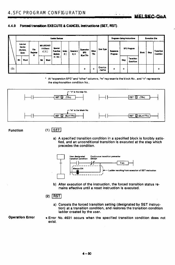
-.
4. SFC , "( _. ... PROGRAM ... * ~ CONFIGURATION . 2 c , hIsiu&G-M 4.4.9 Fotoed transition EXECUTE 6 CAMEL hrstwtkns (SET, R S T ) .
h I I
0 - ' At 'expansion SFC' and 'other' columns, 'm' represents the block No., and 'n' represents
the step/transition condition No..
.n' is the stop No
SET @ (TRn) RST @ (TRn)
I .rn' is tho block No
[SET @ (BLrn\TRn) (RST @ (BLrn\TRn)
I
Function (1) lsETl a) A specified transition condition in a specified block is forcibly satis-
fied, and an unconditional transition is executed at the step which precedes the condition.
User dosignatd Continuous transition proventer
Tran
b) After execution of the instruction, the forced transition status re- mains effective until a reset instruction is executed.
a) Cancels the forced transition setting (designated by SET instruc- tion) at a transition condition, and restores the transition condition ladder created by the user.
Operation Error Error No. 4631 occurs when the specified transition condition does not exist.
4-50
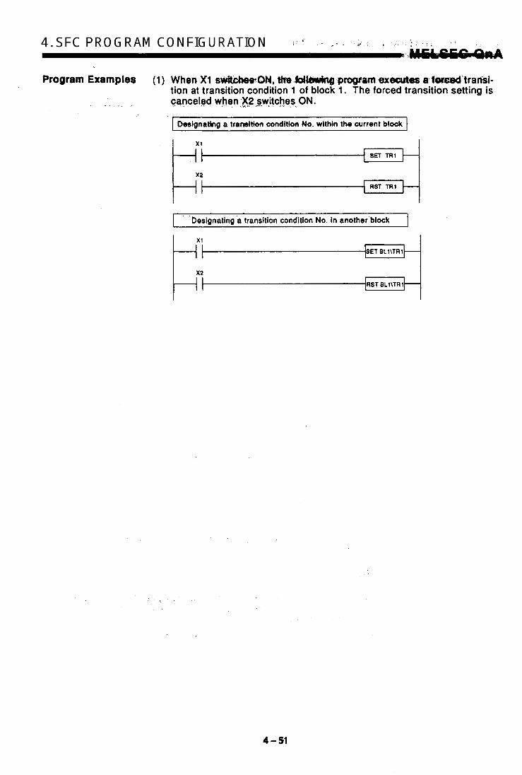
Program Examples (1) When.Xl spvit;cReetCM4, th.WlbWing program exBcutes a folsed'trarlsi- tion at transition condition 1 of block 1. The forced transition setting is
. . , . . canceled when ,X2 yitches . 8. ON.
I Designating a transition condition No. within the current block c
t-' RST TRl
designating a'transition condition No. in another block 1
E:' I-- ET BLl\TRl
-RST L BLl\TRl
4 a
4 - 5.1
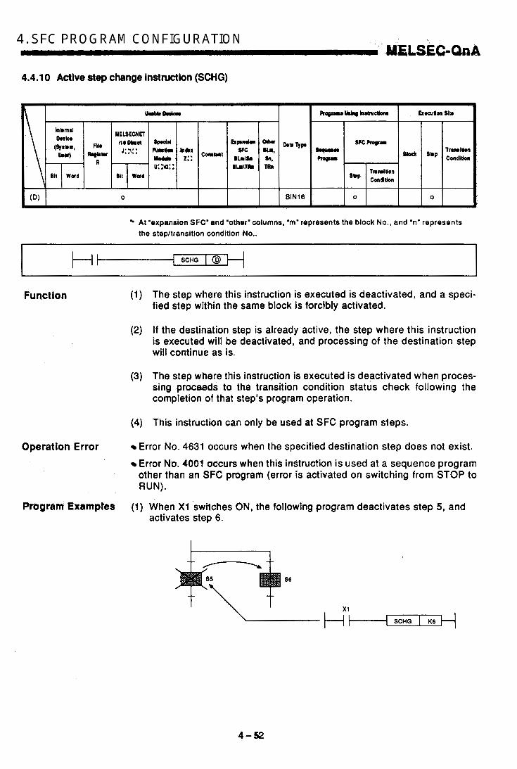
4. SFC r'-* , PROGRAM -. . 5 -> -3 .I CONFIGURATION
4.4.1 0 Active step change instruction (SCHG)
. ' .MELSEC-QnA
AI 'expansion SFC'and 'other'columns, 'm' represents the block No., and .n' represents the stepltransition condition No..
[ SCHG [ @ - Function
Operation Error
.- . .
Prugram Examptes
(1) The step where this instruction is executed is deactivated, and a speci- fied step within the same block is forcibly activated.
(2) If the destination step is already active, the step where this instruction is executed will be deactivated, and processing of the destination step will continue as is.
(3) The step where this instruction is executed is deactivated when proces- sing proceeds to the transition condition status check following the completion of that step's program operation.
(4) This instruction can only be used at SFC program steps.
Error No. 4631 occurs when the specified destination step does not exist. Error No. 4001 occurs when this instruction is used at a sequence program other than an SFC program (error is activated on switching from STOP to RUN).
(1) When X1 switches ON, the following program deactivates step 5, and activates step 6.
S6

4.4.1 1 Bkck switching instruction (BRSET)
0 I I I At 'expansion SFC' and oather' columns, 'm' represents the block No., and 'n' represents the stepltransition condition No..
Function (1) Designates the destination.block number'for an SFC control instruction wtiich specifies only a step (Sm) or transition condition (TRm).
(2) Although 'BLm\Sn" or "BLm\TRn" may be used as the instruction device when designating the destination block number, only a constant (K, H) may be designated at the 'm" of 'BLm", thereby fixing the designation destination. When block switching is executed by this BRSET instruction, a word device can be used for indirect designation, index qualification, etc.
(3) The effective operation range when block switching occurs (by BRSET instruction) varies according to the program being run at the time, as shown below.
a) If the,BRSET instruction is executed at a sequence program, block switching will be effective from the point where the instruction is executed to the END step. At the next scan, the block in question will be designated as 'block 0" (default value) until the point when the BRSET ,instruction is exe- cuted again.
4-53

4. -, SFC ~ . h PROGpRAM . A d Y * CONFIGURATION -. .,. . M€LS€C-.QnA
If the BRSET instruction is executed at sm SFC: prwcam, block switching will be effective only for the step currently being exe- cuted. Even If the step In rfuesflon is the same s t e p , the BRSET instmc- tion must be executed at each block where the Sn and TRn instruc- tions are used. Moreover, within a single step, block switching will be effective from the point where the BRSET instruction is executed to that step's processing END point. When processing is repeated at the next scan following the proc- essing END for that step, the block in question will be designated as the "current block" until the point when the BRSET instruction is executed again.
(Repeated)
Sequence program Sequence program SFC program A EN DIO 0 END Block 'n'
I I I I c ' 0 '0 .c2
I c -
2 z z 2 - - 0'0
2 3 2 z - E 0;
cn X I 5 01 E 2; E 2 ;
b @ cnx b o b o
SnilRn destination Mock
-- L * L - . *~
Block Bfock specif' by inrtruction Current by inslrudion by instruction Current blodc '"lr by instructio?
Block w i 1 i . d B k d r rp.citi.d. BIO~C sp.ci+ibd
Operation Error
- Program Examples
1 scan 1 The block No. designated by the at BLm\Sn or BLm\TRn will be ef- fective regardless of the execution status (ON/OFF) of the BRSET in- struction. When multiple steps are active (at parallel branch, etc.), only the step where the instruction was executed will be effective. To designate blocks at multiple steps, the BRSET instruction must be executed at each of the steps.
Error No. 4621 occurs when the specified block does not exist.
(1) When X1 switches ON, the following program switches the Sn or TRn block number to the block number stored at the DO data register.
Condition
(2) When X2 switches ON, the following program switches the Sn or TRn block number according to the constant at the 21 index register.
1 x 2 I
4-54

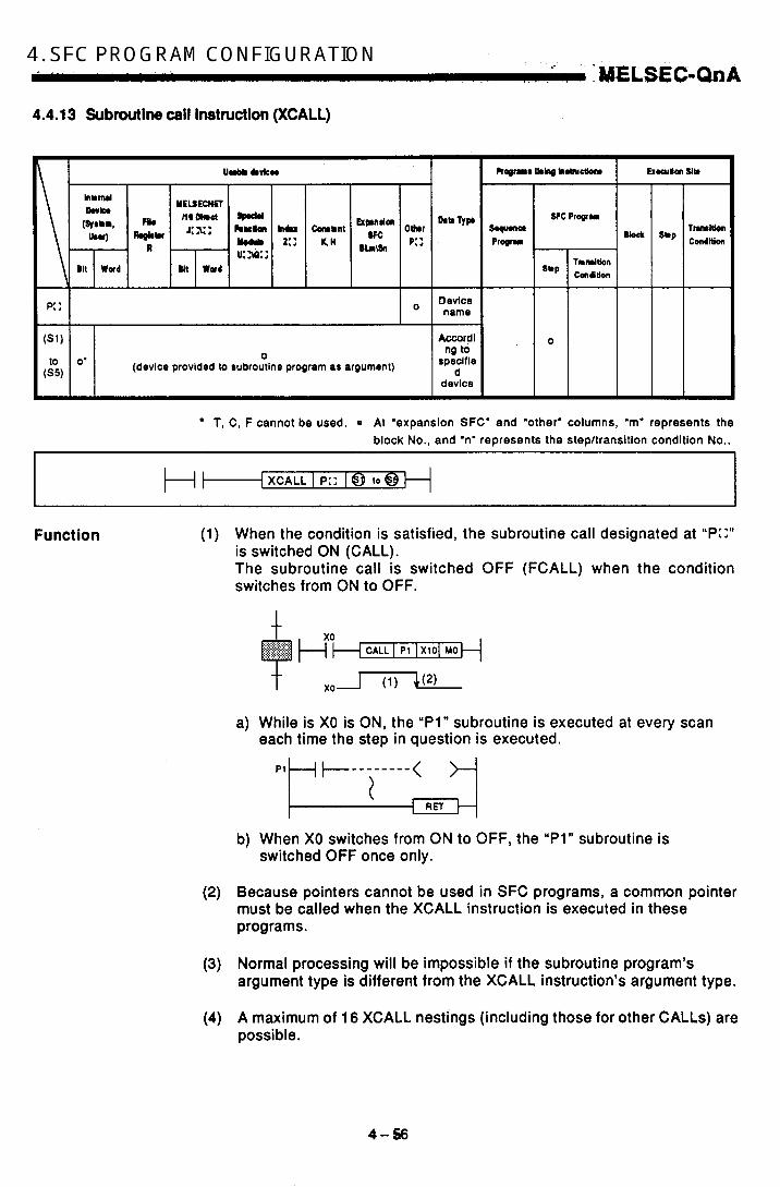
..-
4. SFC PROGRAM CONFIGURATION I ' * 1 , .,*'.; . . ELSEC-OnA 4.4.13 Subroutine c a l l Instruction (XCALL)
T, C, F cannot be used. At 'expansion SFC' and 'other' columns, 'm' represents the block No., and 'n' represents the stepltransition condition No..
I 1 { XCALL I P:: 18 to @
1 I
Function (1) When the condition is satisfied, the subroutine call designated at ''P::'' is switched ON (CALL). The subroutine call is switched OFF (FCALL) when the condition switches from ON to OFF.
a) While is X0 is ON, the "Pl" subroutine is executed at every scan each time the step in question is executed.
J
b) When X0 switches from ON to OFF, the "Pl" subroutine is switched OFF once only.
(2) Because pointers cannot be used in SFC programs, a common pointer must be called when the XCALL instruction is executed in these programs.
(3) Normal processing will be impossible if the subroutine program's argument type is different from the XCALL instruction's argument type.
(4) A maximum of 16 XCALL nestings (including those for other CALLS) are possible.

For details regarding the common pointer and the subroutine program's argument, rq@r to th@ QnACPU Programming Manual (Common Insthctions).
. _ < S I - .. " . L. . I I 1
Operation Error 0 Error No. 4210 . . . . . . . . . . . . occurs.i/.the program for the speci- fied pointer does rioj:qxist. I . '
or STOP instruction is exegpted prior to the RET instruction.
cuted prior to the XCALL instruc- tion.
Error No. 4213 . . . . . . . . , . . . occurs if the number of nestings. ex- ceeds 16.
Enor No. 4211 , . , . . , , . . . . . O C C U ~ S ~ ~ an END, FWD, GOEND,
Error No. 4212 . . . . . . . . . . . . occurs if the RET instruction is exe- .
i
4-!P

4. SFC~ PROGRAM CONFIGURATION AAELSE.GQnA 4.4.1 4 Time check instruction (TIMCHK)
lrumltion Condition
Function
At 'expansion SFC' and 'other' columns, 'm' represents the block No., and 'n" represents the stepltransition condition No..
(1) Measures the condition device ON time, andswitches a specified device ON when the condition device remains ON longer than the designated time setting.
(2) The following devices are used for this instruction. , CoidL- , i' L" TIMCHK 8 @ @
Device switched ON at time-up
Device where measurement set value in stored
Device where memured present value ia stored
Mearurermnt execution condition
(3) When the measurement execution condition switches ON, the device switched ON by the measured present value and the time-up status switches the monitor execution condition OFF. Or, i f the transition condition is satisfied, the status is held. When the present value is cleared to "0" or the device which was ON switches OFF, the measure- ment execution condition will either switch ON again or the program will be reset.
Program Examples (1) The following is a program where the X0 ON time setting is 5 seconds, with the present value stored at device DO, and with device Y10 switch- ing ON when time-up occurs.
t
4-58

4.5 SFC Information Registers
The SI% information registers desiQnated at each block are described in this section. In cases where SFC information register functions are not required, there is no need to designate the register settings when creating the SFC pro- gram. The absence of register settings wit1 not affect SFC program'opera- tion. The devices which can be used for each of the SFC information register types and functions are shown below.
SFC Intormatlon Rogisterr Usable Dovlcea
Block STARTIEND bit Step transition bit Block STOPlRESTART bit Block STOP mode bit Continuous transition bit
'Number of active steps' register D, W, R , ZR
Y , M, L, F, V, B
IRE MARK^ SFC information register settings are designated w h m entering the SFC diagram at the SWOiVD-GPPQ GPP function software package.
4-99

4. SFC PROGRAM CONFIGURATION MElSECFQnA 4.5.1 Block START/END bit
The block START/END bit can be used as a confkmation device when a block is activated by a block START step, or it can be used to execute a forced START or forced END (from sequence program or by peripheral de- vice "test" operation) at a given block.
(1) The block START/END bit can be used for purposes such as providing an interlock when confirming that the sub-block in question is inactive when a sub-block is started by a block START step.
Block 0 Block 5
Block 5's 'block active bit": MO
I
OFF , ,
(2) If the block in question is inactive and is forced ON by the block START/END bit from a peripheral device (test function), that block can be started independently. Moreover, processing of that block can be forcibly ended by executing a forced OFF.
(3) When a forced OFF is executed by the block START/END bit, and the block in question becomes inactive, processing will occur as follows:
0 Execution of the block in question will stop together with all outputs from the step which was being executed. (Devices switched ON by the SET instruction will not switch OFF.) If a START status exists at another block, the STOP will still occur, but the START destination block will remain active and processing will continue. To clear the START destination block at the same time, the START destination's block START/END bit must also be switched OFF.
(4) A block which has been forcibly deactivated is restarted as shown below.
I Relevant Block I Restart Status
When the START condition for
parameter setting. START ON' at the SFC step following END step block 0 is designated as 'auto Operation is restarted from the
parameter setting. END step processing, and block 0 is designated as 'auto
START OFF' at the SFC The is deactivated after When the START condition for
processing. Block 0
processing is restarted from the initial step when another START
I Blocks 1 to 319 I request occurs for that block.

. ..
CONFIGURATION ', . . ' .. - I Related Instructions1 a) SFC control ir)stru,ctiQns
0 Block START instruction (SET BLm), M6ck'END instruction (RST BLm)". : . . . . . . . . . . . . . . . . , . . . . . . . S& Section 4.4.6.
b) SFC diagram symbols 0 Block STAWFstep (e n, EI n) . . , . . . . . . See Sections 4.2.8.
and 4.2.9.
4-61
i
I

. I .
4. SFC PROGRAM , I CONFIGURATION .. .M,US€GOnA
4.6.2 Step trandtkn bit
The step transition bit performs a check to determine if the transition condi- tion for the current step has been satisfied.
Block 'n'
condition 1)
(Transition condition 2)
L r 1 2 t r a n s i t i o n condition 3)
Y3 I
After the operation output at each step is completed, the step transition bit automatically switches ON when the transition condition (for transi- tion to the next step) is satisfied.
A transition bit which is ON will automatically switch OFF when processing of the block in question occurs again.
Example: Step transition bit = M1 ON I ,
If a continuous transition is designated (continuous transition bit ON), the transition bit will remain ON during the next step's operation output after the transition condition is satisfied. It will also remain ON following the execution of multiple steps, even if the transition condition is unsatisfied. In these cases, the transition bit will switch OFF when block execution occurs at the next scan. Example: Step transition bit = M1
"1' ON 1-L OFF -

Tran
sition
con
dition
unt
atisli
ed
Step
'ntl'
Tr
ansit
ion c
ondit
ion u
nsati
sfied
St
ep 'n
t2'
Tran
sition
con
dition
sati
sfied
Othe
r pro
gram
exec
uted
Step
'n'
..
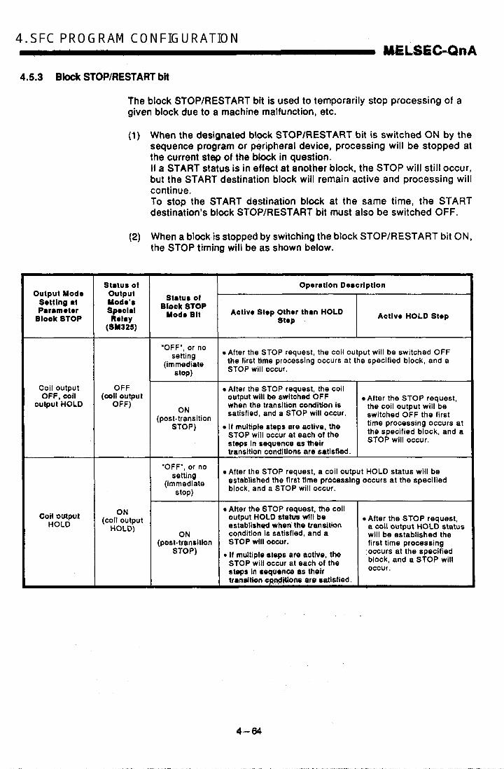
4. SFC PROGRAM CONFIGURATION UELSECLQnA 4.5.3 Block STOP/RESTART bit
The block STOP/RESTART bit is used to temporarily stop processing of a given block due to a machine malfunction, etc.
(1) When the designated block STOP/RESTART bit is switched ON by the sequence program or peripheral device, processing will be stopped at the current step of the ,block in question. If a START status is in effect at another block, the STOP will still occur, but the START destination block will remain active and processing will continue. To stop the START destination block at the same time, the START destination's block STOP/RESTART bit must also be switched OFF.
(2) When a block is stopped by switching the block STOP/RESTART bit ON, the STOP timing will be as shown below.
Output Mode Setting 81 Paramotor
B h k STOP
Coil output OFF, coil
output HOLD
Coil output HOLD
output
Spoclal Yodo'*
(811325) Ri lay
Block STOP Status of
Modo Blt
OFF
OFF) ( c a l l output
'OFF", or no setting
(immediate stop)
ON (post-transition
STOP)
ON (coil output HOLD)
'OFF', or no setting
(immediate stop)
ON (post-transition
STOP)
Operation Deecriptlon
Active Step Other th8n HOLD stop Actlve HOLD Step
After the STOP request, the coil output will be switched OFF the first time Drocessing occurs at the specified block, and a STOP will occur.
- After the STOP request, the coil output will be switched OFF when the transition condition is satisfied, and a STOP will occur.
I f rnultipte steps are active, the STOP will occur at each of the steps in sequence as their transition condltions are satisfied. I After the STOP request,
the coil output will be switched OFF the first time processing occurs at the specified block, and a STOP will occur.
After the STOP request, a coil output HOLD status will be established the first tlme processlng occurs at the specified block, and a STOP will occur.
After the STOP request, the coil output HOLD $ t a m w i l l be establish@ when the transition condition is satisfied, and a STOP will occur.
~ ~~~
After the STOP request, a coil output HOLD status will be established the first time processina

r I (1) The coil, HOLD step hecomes inactiw tha,first time processing
occurs at th+black in qFestion fobwing the STOP request. (2) During SFC program execution, the M325 special relay is switched
OFF wtieh ttre d&ouW' is OFF, a'& is switched ON when the coil output is ON, hr accm#ance.with the parameter setting. The M325, $p&al 'relay e m alsb be switched ON and OFF by the user program without regard to the parameter setting.
(3) Processing el the Mock is restarted from the step where the STOP occufred'when h6 block STOPIRESTART bit is switched OFF at the sequence program or peripheral device. An "operation HOLD status" step (With transitibn check or without tran- sition cheak) which has been stoppedwill be restarted with the operation HOLD status in effect. A "coil output,H.QLD" step cannot be restarted after being stopped as it is deactivated at that time.
(4) Execution of PLS and : Z P instructions after a block STOP has been canceled varies according to the ON (HOLD) or OF$ (all O f F) status of the SM325 special relay (ON: operation output HOLD at block STOP; OFF: all OFF).
SM325 { ON : Not executed O f f : Executed again
(5) When the SFC control "block STOP" instruction {PAUSE BLm) is exe- cuted, the @lock in question is stopped, and the block STOP/RESTART bit switches ON. When the %fo& RESTART" instruction (RSTART BLm) is executed while the block stopped, the block in question is restarted, and the block STOP/RESTART bit switches OFF.
WlNTSl (1) Stopping of program processing by a block STOP/RESTART bit
being switched ON, or by a block STOP instruction, applies only to the specified block.
(2) Even if a block stop is exeuuted for the START destination block, the START source block will not be stopped.
(3) Even if a bkb 's top is executed for the START source block, the START d&#nqtiorl block will not be stopped.
I Related Instructions1
a) SFC information register 0 Block STOP.mode bit . . . . . . . . . . . . . . . . . See Section 4.5.4.
b) SFC control instructions 0 Block STOP instruction (PAUSE BLm) 8 block RESTART instruction
(RSTART BLm) ...................... See Section 4.4.7.
4 ,-%6

4. SFC PROGRAM CONFIGURATION MELSEGUnA 4.5.4 Block STOP mode bit
The block STOP mode bit setting determines when the specified block is stopped after the block STOP/RESTART bit switches ON, or after a stop designation by the block STOP instruction {PAUSE BLm).
(1) The stop timirtg for a block where a STOP request has occurred varies according to the ON/OFF setting of the block STOP mode bit, as shown below.
~ ~~ ~ ~~
Block STOP mode bit OFF
Block STOP mode bit ON
The block is stopped Immediately when the block STOPlRESTART bit switches from OFF to ON, or when a block STOP Instruction is executed. However, It the block STOPlRESTART bit is switched ON within the current block, the STOP will occur when that block is processed at the next scan, or when the instruction is executed. The block is stopped at the step transition which occurs when the transition condition for the current step (active step) Is satisfied. However, the operation output will not be executed for the step following the transition. When multiple steps are active in a parallel branch, the STOP will occur sequentially at each of the steps as their transition conditions are satisfied.
IRelated Instructions1 a) SFC information register
0 Block STOP/RESTART bit . . . . . . . . . . . . . See Section 4.5.3. b) SFC control instruction
0 Block STOP instruction (PAUSE Blm). . . See Section 4.4.7.
4-66

Q W A M I CONFIGURATION 'V
4.5.5 Continuous transition bit
. The continuous transition bit setting determines whether the operation out- put of the next step is to be executed within the same scan after a transi- tion condition is satisfied.
(1) As shown below, SFC program transition processing occurs according to the continuous transition bit setting (ONOFF) designated by the user.
Continuous transition ON . . . . . . . . , . . . . , . When the transition conditions at contiguous steps
are satisfied, all the steps with satisfied transition conditions will be executed at once within a single scan.
0 Continuous transition OFF
Example: Sample program processing n
. . . . . . . . . . . . . . . Steps are executed in a 1-step-per-scan format.
(Block On-) 0 Continuous transition ON
E w e
When the block is activated, all steps are proc- essed within the same scan. The block is then deactivated at the Mock END.
SMUX) H W
i i SM400 0 Continuous transition OFF
Hl-CEDl When the block is activated, steps are proc- essed in a 1-step-per-scan format. The block
SY4W END step is processed at the 3rd scan, and the Ht-C3l block is deactivated. -
(2) A continuous transition can be designated for individual blocks by the continuous transition bit ON/OFF setting, or for all blocks using the batch setting special relay. As shown below, the continuous transition operation (ON/OFF) varies according to the continuous transition bit and special relay (SM323) setting combination.
Special Relay Contlnuou8 Tran8ltlon Bit Status I Status I SFC Program Operation I
Continuous transition bit OFF Operation occurs without continuous transition
SM323 ON No continuous transition bit setting Operation occurs with
' continuous transition Continuous transition bit ON I I
SM323 OFF No continuous transition bit Operation occurs without continuous transition I I Continuous transition bit OFF I I
c
'4 - 67

4. SFC PROGRAM . . . CONFIGURATION MELSEC-QnA
POINT] To shorten tact time, a continuous transition ON status is recommended in order to speed up the step transitions. This will eliminate the waiting time from the point when a transition condition is satisfied untll the point when the transition destination step’s operation output is executed.
4.5.6 “Number of active steps” register
The “number of active steps” value for a given block is stored at this regis- ter.
(1) The “number of active steps” value for a given block is stored.
Specified device
(2) The “number of active steps” value includes normal active steps, coil HOLD steps, operation HOLD steps (with transition check), and opera- tion HOLD steps (without transition check).
4-68

4.6 Step Transition Watchdog Timer
The step transilion watchdpg timer ,is a check function which monitors the time from the'poirii when Bxecufloh Qf a step begins, until the point when transi)ion to the,next step Ocqg,rs, tb'determine'whettwr the transition oc- curred within the pr&ctt'tim'e @tiad; ,
If transition to the next'step:falfs'to'dcCur withirl the designated time period, a preset annLinciaior (FJ'switches ON.
(1) The preset time period and the annunclatbr Q (ON when time-over status occurs) device number are designated at special relays SD90- SD99. The steptransfiion watchdog timer operation begins when these special relays switch ON at the operation outputs of the monitored steps. If the SD90-SD99 special relays switch OFF while a time count is in progress, the time count will be stopped and the timer will be reset.
(2) There are a total of 10 watchdog timers in the SFC program. The special relay and special register allocations for each watchdog timer are shown below.
Watchdog
SM99 SM98 SM97 SM96 SM95 SM94 SM93 SM92 SM91 SM90
Tlnwr 10 T l m r 9 T l m r O T lmr7 n w 6 TlnwrS Tlmr 4 T l m r J T l m r 2 T l m r 1 Watchdog Walchdq Watchdog W l l c b d ~ WaIchdW WrtShdO# WDichdOg Wm4cMog Walchdog
relay
Special register SD90 SD99 SD98 SD97 SD96 SD95 SD94 SD93 SD92 SD91
(3) The setting method at special registers SD90-SD99 is shown below.
b15 to b8 b7 to bO
47 -Time setting
(1 to 255 (setting value x 1 sec))
1 Annunclator (F) (ON when time-over status occurs) device No. setting (0 to 255)
(4) The method for using a watchdog timer is shown below.
t T i m utting...lO x 1 sac - Annunciator (F) No. ... F1
10 '.cI U O V P l c l a l a SDSO
I
"i'i 10 ('=) i 1 #
(a) As shown above, the special relay switches ON at the operation output of the monitored step, and the time count begins.
i
I 4-69
A

.4
4. SFC ~ PROGRAM ~ I" ,.. CONFIGURATION . . ME.-&&..A
(b) If transition condition "a" at the step m question is not satisfied within the designated time (10 secs.) after SM90 switches ON, the F1 annunciator will switch ON. (However, SFC program operation will continue.)
SMQO will switch OFF, the time count will stop, and the timer will be reset.
(c) If transition condition "a" is satisfied within the designated time,
(5) Even i f the annunciator (FO to F255) switches ON, the annunciator's ON detection count and the annunciator number will not be stored at SD62, SD63, or SD64 to SD79.
(6) The same step transition watchdog timer can be used at more than one step provided that the steps are not concurrently active.
Example:
t 4 5 Watchdog timer 1
5 As there is no chance that steps 5 and 6 will be concurrently ac- tive, the same watchdog timer 6 Watchdog timer 2
6 can be used at both steps.
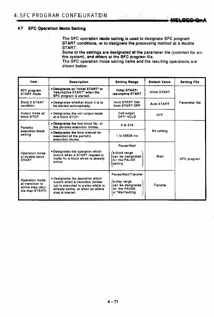
4.7 SFC Owation Mode Setting
Item
SFC program START mode
Block 0 START condition
Output mode at block STOP
Periodic execution block setting
Operation mode at double block START
Operation mode at transition to active step (dou- ble step START)
The SFC operation CrPodB setting is used to designate SFC program START conditions, GM tct designate the processing method at a double START. Some of the settings are designated et the parameter file (common for en- tire system), anti & h s at the SF0 program file. The SFC operation mode setting itehs and'the resulting operations are shown below.
Descrlptlon I Setting Rangr
Designates an 'initial START' of 'resumptive START' when the SFC Prowam is started. I Initial START/
rerumptive START
Designates whether block 0 is to Auto START ON1
at a block STOP. OFF/ HOLD
Destgnates the first block No. of the periodic execution blocks. 0 to 319
Designates the time interval for erecution of the periodic execution blocks.
1 to 65535 ms
Designates the operation which occurs when a START request is made for a block which is already active.
Designates the operation which occurs when a transition (follow- up) is executed to a step which is already active, or when an aktive step is started.
I PauseMait
a block range
[setting ] can be designated for the PAUSE
PauselWaiVTransfer
4 -71
Initial START
No setting
Wait
Transfer
SFC program

P
4. SFC PROGRAM 1 . . , - CONFIGURATION
4.7.1 SFC program START mode
WLBEW
The SFC program START mode setting determines whether an SFC program STAR.T (SM321 OFF + ON) is executed by an initial START, or by a resumptive START from the preceding execution status.
(1) Settings and corresponding operations
The SFC program START format can be designated as an "initial START" or a "resumptive START". As shown below, the operatian which occurs depends on the parameter and special relay (SM322) setting combination.
Setting Operation description SM322 r t a tu r '' Initial START Initial START
(default) ONlOFF When 'auto START ON' is designated fur btock 0: ........ Block 0 is executed from its initial step. , When 'auto START OFF' is dodgn@ted for block 0:
OFF ........ The block started by the SFC control 'block START' instruction is
Resumptive START executed from its initial step.
ON Resumptive START A resumptive START is executed from the previous active status.*2
'1: When CPU STOP 4 RUN switching occurs, SM322 is switched OFF or ON in accordance with the parameter setting (OFF i f an 'initial START' is designated, and ON i f a 'resumptive start' setting is designated).
'2: The 'previous active status' is the status which was active when SM321 was switched OFF during SFC program execution, or when a CPU reset or power OFF occurred.
4.7.2 Block 0 START condition
The block 0 START condition setting determines whether block 0 is auto- matically started and activated when an SFC program START occurs (SM321 OFF 4 ON).
(1) Settings and corresponding operations
An "auto START ON" or "auto START OFF" setting is designated for block 0. Operations which occur at the SFC program START and at the block EN0 are shown below.
Oporaltlon
At SFC Program START At Block END (Block 0 ) Setting
Auto START ON The initial step is automatically activated 0 Block 0 is autbmaticaiiy activated, and is (default) again at the block END. executed from tts initial step.
Block 0 is activated by a START request Auto START Block 0 is deactivated at the block END, resulting from an SFC control 'block
START' instruction or a block START step, in the same manner as other blocks.
and waits for another START request.
4 -72

The *output mcde a? bloak 6 T W setting determines whether an output (designated by,OUT 4iWu&ion) is to remain ON or be switched OFF when a temporay 570PaCmrs at a,given bbxk in response to the SFC informa- tion register's STOP/RESTARJ bit or the SFC control "block STOP" (PAUSE Bdm) instruction.
(1) Settings and corresponding operations
Either an 'output HOLD" or. an 'outpot forced OFF" setting can be des1gnated'ps"the"outpot mode wherva block STOP occurs. As shown betaw, the operatton which OCCUTS depends on the parameter and special relay (SM325) settmg combination.
Coil output 0 FF
(default), coil output ON
1 Block STOP I Oporation SYs25 81atua Clod. Bft I sturc. Actlvo Stopa Othor than
Oporatlon HOLD Stop8 Operation HOLD Steps I
'OFF', or no settfnq '
instruction, and operation stops. (immediab Operation output's coil output switches OFF at the STOP
OFF
OFF)
STOP) (coil output
ON (post-transition
the operation output's coil output switches OFF when the transition condition Is ST0 P)
switches OFF at the STOP
stops. satisfied, and operation stops. instruction, and operation
eAltor the instructbn~ Operation output's coil output
'OFF', Or no Setting
Instruction, and operation stops. (immediate A coil output HOLD status is established at the STOP
ON STOP) (coil output
HOLD) A coil output HOLD status is After the STOP instruction, a ON coil output HOLD status is
(POSt-tranSlHon established when the instruction, and operation transition condition is ST0 P) established at the STOP
satisfied. and omration s t o m
(1) The coil HOLD step becomes inactive the first time processing occurs at the block in question following the STOP request.
(2) When CPU STOP -+RUN switchinguccurs, the SM325 special relay is switched OFF when the coil output kOFF, and is switched ON when the coil output is ON, in accordance with the parameter setting. The SM325 special relay can also be switched ON and OFF by the user program without regard to the parameter setting.
4-73

4. SFC . I . . . PROGRAM " CONFIGURATION ..I- 4bELsEGuAA . ,
4.7.4 Periodic execution block setting
The periodic execution b k k setting designates the execution of a given block at specified time intervals rather than at each scan.
Setting items
Designate the first block number and the time of execution for the periodic execution blocks. When these settings aredesignated, the "first block" and all subsequent blocks will becom'periodic axecution blocks. The execution time interval setting can be designated in 1 ms units within a 1 to 65535 ms range.
Periodic execution block operation method
Periodic execution block operation occurs as shown below.
Execution interval Execution interval (1) Sequence programs executed at each scan (2) Blocks executed at each scan (3) END processing (4) Periodic execution blocks
(a) Until the'specified time interval elapses, only the sequence pro- grams and btodrs designated for execution at each scan will be executed.
(b) When the specified time interval elapses, the periodic execution blocks will be executed following execution of blocks designated for execution at each scan. If the specified time interval is shortgr than.the scan time, the peri- odic execu.fiotr blocks will be exeCuted at each scan in the same manner as €he other brad<$.
manner. &) The specified time in@tvakcountdow is executed in a continuous
4-34
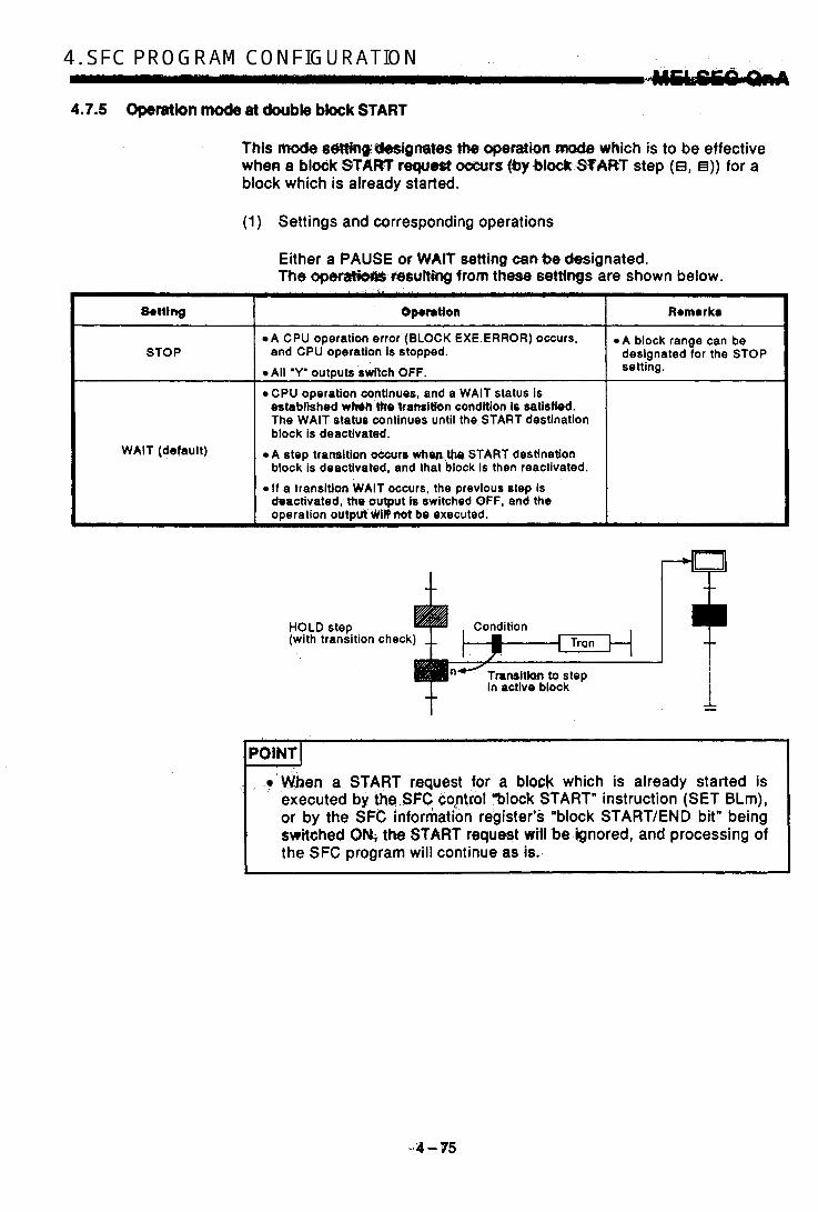
W F r _ l ; i . f l A M CONFIGURATION - 4.7.5 Operetkn mode at double bbck START
This ftmde se#ingWgrtates the operation mode which is to be effective when a blodk'START request ,ocwrs (by .block.S3ART step (e, e)) for a block which is already started.
(1) Settings and corresponding operations
Either a PAUSE or WAtT setting can be designated. The 0pemMm resulting from these setthgs are shown below.
S T 0 P
WAIT (default)
Operatton
A CPU operation error (BLOCK EXE.ERROR) occurs,
All 'Y' OUtDUtS switch OFF. and CPU operation is stopped.
CPU operation continues, and a WAIT status is established wMn Me:'Iransltion condttion is satisfied. The WAIT status continues until the START destination block is deactivated.
block is deactivated, and that block is then reactivated.
deactivated, the output is switched OFF, and the omration outalrt vVilYIsot be executed.
A step transition occur6 whm,t!m START destination
If a transitian WAIT occurs, the previous step is
Remarks
A block range can be designated for the STOP setting.
+ HOLD step Condition (with transition check
I m.-L Tran
POINT~ . e When a START request for a block which is already started is
executed by the.SFC coptcol "block START" instruction (SET BLm), or by the SFC information register's 'block START/END bit" being switched ONi t h e START request wHIsbe:ignored, and processing of the SFC program will continue as is.
' 4
I I

, .-
4. SFC PROG,RAM CONFIGURATION
4.7.6 Operalion mock st transition to acthre step (double gtep START)
-I--
This mode setting designates t h e operation mode which is to be effective when a follow-up function such as an operation HOLD step (with transition check) is used to execute a transition to a step which is already active.
(1) Settings and corresponding operations
A PAUSE, WAIT, or TRANSFER setting can be designated. The operations resulting from these settings are shown below.
~~~ - ~~
Setting Remarka Oporatlon
A CPU operation error (BLOCK EXE.ERROR) occurs,
e All 'Y' outputs switch OFF.
A step range can be PAUSE designated for the STOP and CPU operation is stopped.
setting.
WAIT
CPU operation continues, and a WAIT status is estabtished when the transition condition is satisfied. The WAIT status continues until the START destination step is deactivated.
A step range can be designated for the WAiT
If a transition WAIT occurs, the prevlous step is setting. deactivated, the output is switched OFF, and the operation output will not be executed.
previous step is deactivated and absorbed by the transition destination step.
CPU operation continues, the transition occurs, and the
TRANSFER (default) a Active step Inactive
Setting
PAUSE,
WAIT,
TRANSFER
(2) Transition to HOLD step by double START
The following table shows the transition procedure for transitions to coil HOLD steps, operation HOLD steps (with transition check), and opera- tion HOLD steps (without transition check) which occur when the double START condition is satisfied. These transitions occur without regard to the settings described at item (1) above.
Operation
The TRANSFER setting applies to all operations, regardless of the
At coil HOLD steps setting.
....... The operation output is restarted, and a transition condition check begins.
....... A transition condition check begins.
....... Operation continues as is.
A! operation HOLD steps (withnut transition check),
At operation HOLD steps (with transition check)
Active step Inactivo
Transition condition ratirfid
Coil HOLD stop or *ration output step => (without transition ch.ck) Tranrition condition
(No transition condition check)
4-76
~~
Remarks
Following the double START, execution of all subsequent steps where transition conditions are satisfied will occur according to the step attributes.
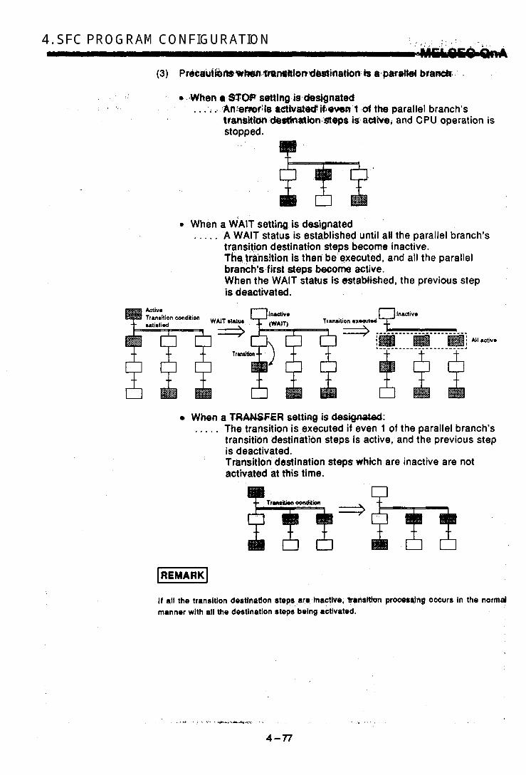
0 When a WAIT setting is designated i
. . . . . A WAIT status is established until all the parallel branch's transition destination steps become inactive. Thq transition is then. be executed, and all the parallel branch's first steps become active. When the WAIT status is established, the previous step is deactivated.
h
L ;
T r d t i o n oxoeutd
i When a TRANSFER setting is desrga;rteb: IC
. . . . . The transition is executed if even 1 of the parallel branch's + transitian destination steps is active, and the previous step l
is deactivated. Transhion destination steps which are inactive are not activated at this time.
U
B i i
t
if all the transition destlnatlon steps are inactive, gnsttion prOCesaing occurs in the normd manner with ail the destination steps being activated. I
*I /I

4. SFC .. .“.” PROGRAM . . . CONFIGUl?“l W L S G C h A
I POINT I The “operation mode at transition to active step (double step START)” setting applies at transitionscaused by satisfied transition conditions, and at forced transitions caused by the SFC control “transition con- trol” instruction (SET TRn). If the SFC control “step control” instruction (SET Sn) is used to request a START at a step which is already active, the request is ignored, and processing continues as is.
4-78

-AM PROCESSING SEQ"X . , .--
5. SFC PROGRAM PROCESSING SEQUENCE
The processing sequence for SFC programs is shown below.
Resumptive start What is the SFC . . . . .
OFF Initial START 0
Is SM322 ON?
I A
System starts automatically at CPU power ON or at STOP -$ RUN switching in order to switch SM321 ON. i f SM321 is switched OFF before SFC program scanning begins, the SFC pro- gram will not be executed until SM321 is switched ON. An SFC program initial START or re- sumptive start setting is designated at 9 [ the SFC parameter setting. When a resumptive start setting is designated, the system switches SM322 ON. i f SM322 is switched OFF before SFC program scanning begins, the initial START setting will be designated.
, \L
Auto START OFF . . . . . A block 0 'auto START ON' or 'auto START OFF' setting is designated in the SFC parameter settings.
Auto START ON If 'auto START ON' is designated, block 0 is executed from its Initial step. I f 'auto START OFF' is designated, operatlon begins from the initial step of the block designated by another pro- gram f i le 's SFC control instruct ion
Has block START
. (START request). Execution from initial ate of Execution from initial step of block designated by STAkT block 0 request
I
Has SM321 switched OFF? + SFC propram execution END
I
, ,
5 - 1 F

5. SFC PROGRAM .~ - . PROCESSING SEQUENCE
5.1 Overall Program Processing
Mt§EC-Qf lA
The overall QnACPU program processing operation is described in this sec- tion. For more detailed information, refer to the QnACPU User's Manual.
5.1.1 Program processing sequence
The QnACPU can store several programs in the program memory and manage them as files; file execution can be designated for a specified file only, or for multiple files simultaneously. The overall operation format is shown below.
I CPU RUN
Initial program
I m Scan program
J
1 I
Started only , (4) 7 1 when required
4 c
program Low-speed
u WAIT program
-1 I Execution time monitoring
END END END CPU RUN processing processing processing
(3) , (1 ) I
t -L -I- -L Initial scan 1 scan 1 scan
0 The longer of the "surplus constant scanning time" or the desig- nated "low-speed program execution time" is adopted for the low- speed program (3).

I Execution Type I Description I S#d Comp8tibility I ' 5 . 1 ,:PI - 9 t :
~ ~ ~~ ~
a 1 scan only h executod at power ON, or at STOP + ~ ~~
(1) Initial program (initial execution) RUN switching. X
1 0 The WAIT program ia wed from that point on. r
(2) Scan program (scan execution) File which is executed at every scan. 0
(3) Low-speed program The execution time for this file is either the surplus constant s.canning time, or the preset low-speed X
4lOW.8Pd * X ~ U t i ~ ) exemuan This file Is fer subroutlnes or interrupt programs, etc.
(4) 0 WAIT program (waiting) Started by. p r q p n start instruction.
(1) The SFC program can execute only one of the 'scan execution' files. To start a WAIT program, the SFC program where scanning is currently in progress must first be designated as a WAIT program. Refer to section 5.1.2 for details regarding the 'scan execution t) WAIT program' switching procedure.
(2) The 'execution type' settings for the program files are designated at the 'program setting' item of the auxiliary parameter setlings.
. . . , . , .
5 - 3
I

h
5. SFC PROGRAM PROCESWO SEQUENCE 1 . , M€LSECICZnA
5.1.2 Execrrtion type designation by instructiocw
The “execution by instruction” function enables the use of instructions to change the execution type designated by the ‘program setting” parameter. Details on execution type designation by instructions are given below.
(1) Instructions and corresponding operations
Imtruation
PSTOP
POFF
PSCAN
PLOW
Oprratlon I SFC Compatlbillty
Designates a WAIT status at the specified block, beginning from the next scan. X
Designates END prooesdng for all blacks of a specified SFC program from the next scan, with a WAIT status established at the 2nd scan following execution of the 0 instruction. Designates scanning of a specified program, beginning from the next scan. If multiple programs are specified, the execution sequence is determined by the
Designates low-speed execution of a specified program, beginning f r o m the next
i f multiple programs are specified, the execution sequence is determined by the
0 ‘program setting’ parameter.
scan.
‘program setting‘ parameter.
X
The following conditions will result in an operation error:
When the specified program does not exist. (error No. 2410).
At execution of the PSCAN or PLOW instruction when scanning or low-speed execution of the specified program is in progress (error No. 241 1).
When an SFC program is designated by the PSCAN instruction while scanning is in progress at another SFC program (error No. 2412).
The SFC control PCHK instruction can be used to check whether or not the specified SFC program is currently being executed. For details regarding the PCHK instruction, refer to Section 4.4.12.
(2) Instruction format
lnslructbn Program name
Character string or word device where character string is stored PSTOP, POFF, PSCAN, PLOW

(3) Processing time requitsd to switch SFC program from.WAiT status to scan status
The processing time required to switch an SFC program from a WAIT status to a scan status Is shown below. Although the scanning time is extended by the amount of the processing time, this wilt .not result in a watchdog timer error detection.
Switching time (pS) = (number of created programs x 20) + (number of created steps x 40) + (SFC program capacity x 2)
Example: Number of created programs: 30, Number of created steps: 1200, SFC program capacity: 20K sequence steps (30 x 20) + (1200 x 40) + (20K x 2) = 89560 pS = 89.56 ms
No system processing time is requlrrd when switching from a scan status to a WAIT status. 4
i I +
4
i
5-5 1
I . t

5. SFC PROGRAM PROCESSiffi SEQUENCE MLSEGQnA
5.1.3 SFC program for program ewecution management
This SFC program can be used to manage the program execution se- quence when multiple program file switching is required. Unlike scan execution SFC programs, this program execution management SFC program can consist of only 1 file with 1 block.
(1) Program execution management SFC program creation procedure
(a) Number of files and blocks Only 1 file with 1 block is possible when created as a scan execution program.
(b) Usable instructions Except for block START step 6, I symbols, all SFC diagram sym- bols, steps, and sequence instructions for transition conditions used at normal SFC programs may be used.
POINT I i
0 A “BLOCK EXE.ERROR” (error No. 4621) will occur if the block START step e , e symbols are used.
(2) Execution procedure
The program is started automatically when registered as a scan execu- tion file. After block END processing, the initial step is reactivated, and processing is repeated.
The setting which determines whether a program is a ‘program execution management SFC program’ or a ‘normal SFC program’ is designated with the SWOIVD-GPPQ programming software package. For details regarding the setting procedure, refer to the GPPQ Operating Manual (SFC).
5-6

(3) Example of program mecutlon management SFC programs
SFCI .QPR;. SFO2QPRmd-WCt3iQPR are assumed to be SFC program files and SQ.QPR is assumed to be a program file for a program other than an SF6 'pagram.
0 Scanning of the 'zero return'. etc., pre- procesbing control SFC program and the constant monitoring sequence Program is executed.
An SFC program WAIT status is estab- lished at the zero return END signal.
When an SFC program (SFC1) WAIT status 1s established, a selection transl- tlon occurs If condition 3 (product type, etc.) is ON.
0 m l n g of SFC program for automatlc operatlon Is executed.
An SFC program WAIT status is estab- llshed when the automatlc operatlon END condition is satisfled by a cycle STOP or emergency STOP, etc.
When condition 4 is satisfled (normal END by cycle STOP), a block END oc- curs, and SO Is reactivated after the van- sltlon condition is satlsfled.
When condition 5 is satlsfled (forced END by emergency STOP, etc.) a seiec- lolr-transltion to 52 occurs after the tran- EM kondltlon 1s satlsfled.
0 Scannlng of the error processing SFC program Is executed.
An SFC program WAIT status Is estab- liehed when condltlon 6 Is satisfled (er- ror processlng END).
When error procesring Is completed and the transition condltlon Is satlsfled, a block END occurs, and SO is reactlvated.
The processing sequence when transition condition t4 is satisfied is the same as that shown above except for a different 'product type'.
i
i
I
5-7 I
i

5.2 SFC Program Processing Sequence
5.2.1 sH= program execuUm cycle
The SFC program execution cycle is one time per scan while the SFC pro- gram STARTBTOP special relay (SM321) is ON. Example: Under the conditions shown below, the execution cycle would be
as follows: Condition (1): Program sequence ABC (sequence) <scan>
designated by <scan> parameter setting <low-speed>
Condition (2): Parameter setting for low-speed program time:
Condition (3): Automatic START designated for SFC program 20 ms
CPU RUN
--------. ABC SFC END XYZ
execution execution execution program execution processing Program program execution processing program ABC SFC END XYZ
foT 20 mr execution for 20 ms
* I scan 1 scan
Refer to Section 6.1 for debits regarding the SFC program STARTISTOP procedure.
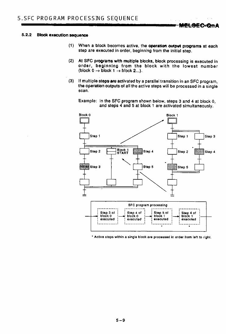
5.2.2 B W execution sequence
When a block becomes active, the operation olttgw? programs at each step are executed in order, beginning from the initial step.
At SFC programs with multiple blocks, block processing is executed in order, beginning f rom the b lock wi th the lowest number (block 0 + block 1 + block'2 ...).
If multiple stepsare activated by a parallel transition in an SFC program, the operation oldputs of all the active steps will be processed in a single scan.
Example: In the SFC program shown below, steps 3 and 4 at block 0, and steps 4 and 5 at block 1 are activated simultaneously.
Block 0 Block 1
+ +
Active steps within a single block are processed in order from left to right.
5-9

5. SFC PROGRAM PROCESStNG SEQUENCE . - . . - I .
. . #,. . I i. i MELSEG.OnA 5.2.3 Step execution sequence
The step operation output programs are executed at each scan while the SFC program START/END special relay (“21) is ON.
(1) Execution sequence from program START to the transition to step 1 of the SFC program
When the SFC program START/END special relay (SM321) is switched ON and a program START occurs, the execution sequence from the initial step to the transition to step 1 occurs as shown below.
CPU RUN END processing END processing END processing
I I
(SM3210N) (SM3210N) (SM3210N) 1 &!;;tion 1 I (0;pepn 1 ] & y p l 1 lnitlai step initial step Step 1
executed) executed) executed) SFC program Block 0 1-1 - -
(Transition condition (Transition conditlon Unsatisfied)
(Transition condition unsatisfied) unsatisfied)
The status of the transition condition for a transition to the next step is checked at the completion of each step’s operation output.
Condition unsatisfied : The same step’s operation output is exe-
Condition satisfied : All outputs of,the executed step are cuted again at the next scan.
switched OFF by that step’s OUT instruc- tion, and the next step’s operation output is executed at the next scan.
When a transition condition is satisfied and SFC program processing proceeds to the next step, the operation output of the previous step is deactivated. The CPU only processes the operation output of the step which is currently active, and the transition condition program for a transi- tion to the next step.
If a step attribute designates a step as a HOLD step, that step will not be deactivated, and processing will continue in accordance with the attribute.
If the continuous transition bit at a give block is set to ON, processing will proceed to the next step when the transition condition is satisfied, without ending the SFC program at the end of each step’s operation output.
CPU RUN END processing END processing I
(“21 ON) (SM3210N)
executed) Initial step (operation Step 1 (operation output executed) output executmj) SFC program Block 0 1-1 I
(Transltlon condition (Trandtion condition (Tran8ltion condition unsatlsfled) unsatisfied) unsatisfied)
5-10
POINTI . ,
The contiwouS;trawition ON setting is recommended for faster tact times and ,441, tf@n&ioqs, A continuous transition ON setting eliminates the waiting time from the point when a transition condition is satiqfied until the point when the operation output for the fransitlon'destination step is executed. For further details, see Section.6.2.4.
5-11
J i

,-
AM PROCESSING S.EWENCE
5.2.4 Conttnuaw tmnsition 0NK)FF opeFetbn
SFC program transition processing can occur with or without a continuous transition, depending on whether t h e continuous transition bit device desig- nated by the SFC information register is set to ON or OFF by the user.
Continuous transition ON . . . . . . . . . . . . . When the transition conditions for contiguous steps
are all satisfied, all these steps will be executed in a single scan.
Continuous transition OFF . . . . . . . . . . . . . 1 step is executed at each scan.
(When multiple steps in a parallel branch are active, the entire parallel branch is executed.)
Example: Sample program and corresponding processing
(Block 'n.)
SM400 }+Ir- When the black became8 active, all steps will be executed in
W h 'continuous transition OH' setting:
a single scan. Block END processing then occurs, and the block is deactivated.
t A , ' r m With 'continuous transition OFF' setting: When the block becomes ective, step execution occurs in a 1-ste -per-- kwmat. Block ZND processing occurs at the 3rd scan, and the block is deactivated.
SM400
SM400 HFG3-I -

(1) Transition processing for %mtiRuous trmsiiionON” setting.
The SFC w a r n prwessing procedure fora ‘uontinuous transition ON” setting is shown bebw.
(1 ) Active step (n) ladder oprratlon I
1 4
(2) Transition condition aallsflrdlunratlsiied check I
When transition condition
(3) END processlng (3)’ The acllve ste (n) Is deactivated. and the coil where me OUf Instruction Is ON is sw i t chd OFF.
(4)’ Step ‘n+l’ is activated, and its ladder operation
I Occurs. 1
(4) Ledder pracesdng tor ihe same atop (n) I I as that at the prevlwr scan. (5) ’ Transition condition satisfiedlunsatisfied check
J
(6) ‘ Subsequent processin Is executed in a continuous manner up to a step wpth an unsatlsfied transition condition.
(7)’ END processing
i f other blocks exist subsequent the block In question. E N D processing will be executed
those blocks have been processed.
(8)’ Ladder operatlon is executed for the step activated by the satisfied condition at the previous scan. I
IPOINT I 0 END processing occurs following the execution of all program files
designated at the program setting parameter as “scan execution” files. For details regarding the processing sequence, etc., refer to the QnACPU User’s Manual.
I
I
i
1
1 1
J
5-13

5. SFC . PROGRAM . ,. * . ,-, - - PROCESSING SEQUENCE 7 . r ' MIELSGGQnA
(2) Transition processing for 'continuous transition OFF" setting
The SFC program processing procedure for a 'continuous transition OFF" setting is shown below.
I t
P
. .,-
(1 ) Actlve step (n) ladder operation
I 1
(2) Transition condition satisfiedlunsatisfied check
(3) END processing (3)' The active ste (n) is deactivated, and h e coil where the O U f Instructlon is ON Is switched OFF.
I (4)' END processing
1 If other blocks exist subsequent h e block in question. END processing will be executed
(4) Ladder procos.lng for the same step (n)
I as that at the previous scan. those blocks have been processed. 1
I I (5) ' Ladder operation is executed for the step activated I by the satisfied condition at the previous scan.
fPOlNTl 1 END processing occurs following the execution of all program files designated at the program setting parameter as "scan execution" files. For details regarding the processing sequence, etc., refer to the QnACPU User's Manual.
5 -14

The SFC program's STARTISTOP special relay (SM321) is automatically switched ON when CPU STOP + 'RUN switching occurs, and the SFC program is automatically started. At other program files, SFC program processing can be temporarily inter- rupted and restarted by switching SM321 OFF and ON.
r I
YES I Was SM321
switched ON or OFF at
file?
A Is SM322 ON?
1 ON
Initial START
5= SFC program execution
I I OFF
1- SFC program not executed
1 I SFC program not Bxocuted I
(1) The processing which occurs when ad SFC program is designated as a WAIT program by the TOFF" instruction is identical to that when "SM321" is switched OFF.
(2) The processing which occurs when an SFC program 'scan execu- tion" status is designated by the "PSCAN" instruction is identical to that for a "CPU RUN" condition.
I I
'6-1
I I

6. SFC PROGRAM EXECUTION .W&SEG-Q##A
6.1.1 SFC program resumptive START procedure
The SFC program START format can be designated as "initial START" or 'resumptive START'. The "resumptive START" setthg procedure as well as some precautions regarding the "resumptive START" format are described below.
(1) Resumptive START setting procedure
An SFC program resumptive START format can be designated at the 'SFC program START mode" item of the SFC parameter setting.
(2) Block operation status resulting from "SFC program START mode" setting
The block operation statuses which correspond to the "SFC program START mode" settings (SfC parameter setting) are shown below.
SFC Program START Mode
Setting Operation Status SM322 Status *'
Initial START ONlOFF Initial START
(default) When 'auto START ON' is designated for block 0: ........ Block 0 Is executed horn RE Initial step. When 'auto START Wf' is desjgnated for block 0 : *'
Resumptive START
OFF ........ The block started by the SFC control 'block START' instruction is executed from its initial step.
ON Resumptive START A resumptive START is executed from the previous active status. *3
'1 : When CPU STOP RUN switching occurs, SM322 is switched OFF or ON in accordance with the parameter setting (OFF i f an "initial START' is designated, and ON i f a 'resumptive start" setting is designated).
'2: The block 0 auto START ON/OFF setting is designated at 'block 0 START condition' item of the SFC parameter settings.
'3: The 'previous active status' is the status which was active when SM321 was switched OFF during SFC program execution, or when a CPU reset or power OFF occurred.
6-2

~OINTS I , .
(1) When a reswptive ST,ART occurs following a PC power OFF or reset, the SFC program's STOP positionwill be maintained (HOLD), but the statuses of the devices used at the operation outputs will not. Therefore, a latch setting must be designated for devices where a HOLD condition is required in addition to execution of a resumptive START.
(2) The special function module is initialized when a PC power OFF or reset occurs. Initial programs for the special function module should be created at constantly active blocks or programs other than SFC programs.
(3) After making SFC program changes (SFC diagram modifications such as step additions or deletions, etc.) while a "resumptive START' setting is in effect, switch to an "initial START" setting, then back to the 'resumptive START" setting in order to register the changes. Failure to do so will result in a START executed from the pre-change step number, causing a mechanical system malfunc- tion.
(4) If a CPU reset occurs during SFC program execution with a "re- sumptive START" format, an 'initial START" status may be desig- nated when the system is restarted due to the reset being interpreted as a 'resumption disabled" condition.
6-3

r”.
.-
6. SFC PROGRAM ,,” ., ..i.l EXECUTION
6.2 Block START and END
- . , \ I W i L S € E 9 n A
6.2.1 Block START method8
The block START methods during SFC program execution are described below. As shown below, there are several block START mathods. Choose the method which is most suitable for the purpose at hand.
START Mothod
4t SFC program START
Auto START ON
Auto START OFF
Block START by SFC jiagram symbol
Block START by SFC control inrtructbn
Block START by SFC inkrmation ngktaf
Operation Dsrcrlpt lon
When the SFC program is started, block 0 is automatically started, and is executed from its initial step.
A START request is designated from another sequence program for a specified block. The specified block is then started and executed from its initial step.
Another block is started by the block START steps (B,B) at each of the SFC program blocks. m
m START occurs
t I
I Using an SFC control instruction, a specified black is forcibly started from an SFC program step (operation output), or from another sequence program. (1) When specified biock is
executed from its initial step:
‘m’ is the block No.
(2) When specified block is executed from a specified step:
Condition
* ’m’ is the block No., .n” is the step No.
A specffied block is started by forcing the ‘block STARTlEND bit’ ON from a program or a peripheral device. The ‘block STARTlEND bit’ is designated at each block as an SFC Information realster.
6-4
Remarks
Convenient when block 0 Is used as a control block. pre-processing block, or a constant monitoring block. Convenient when the started block is to be variable (product type, etc.) when the SFC program is started. A sequence program other than the SFC program must be-designated at the program setting parameter.
Convenient for automatic operations, etc., where the sequence control is clearly detined. There are 2 types of block START: The START source step remains active until the START destination block is ended. The START source transition occurs without waiting for the START destination block to be ended lSFC diaaram svmbol: Rm).
Convenient when starting an error resetting block (when error detection occurs), and for executing interruption processing.
Convenient for debugging and test operations in 1-block units because h e block can be started from a peripheral device without requiring a program.

6.2.2 Bkck END methods
END Method
Block END by SFC diagram symboi
Block END by SFC control instruction
Block START by SFC information register
The methods for ending block operations are described bekw. As shown belop, there are several block END methads. Choose the method which k most suitable for ttie purpose at hand:
Opomtfon Doacilptkn
*BJockpraforskrgiaandedoAdthoblock& deactivated when the block's END step is executed. - ENDstep
Using an SFC control instruction, a specified block Is forcibly ended and deactivated from an SFC program step (operation output), or from another sequence program.
b H G - q Condition
' Om' is the block No. ' Block processing is also ended when the
RST BLrn\Sn Instruction is used to deactivate all steps at a specified block. . A specified block is ended by forcing the
'block STARTIEND bit' OFF from a program or a peripheral device. The 'block START/END bit' Is designated at each block as an SFC information register.
Asmarkr
Convanion! for cycle stops at automatic
Multiple END steps are possible within a
operations, etc.
single block.
Convenient for executing a forced STOP (at emergency stops, etc.) without regard to the operation status.
Convenient for debugging and test operations because block processing can be ended from a peripheral device without requiring a program.
POINTS ~~
(1) A forced end to block processing is possible using a method which is different from that used to start the block. Example: 1. A block started by an SFC diagram symbol (E, e) can
be ended by an SFC control instruction (RST BLm).
2. A block started by an SFC control instruation (SET BLm) can be ended by forcing the SFC information register's 'block START/END bit" OFF.
as shown below.
Block I
When the block 0 START Mock Pfocessing Is condition is as 'auto START ON' started automatically from
ended, processing is
Block 0 the Initial step. Wben the block 0 START After block p r m r d n g Is condition 14 depigaated as ended, the block remains l w t o START OFF' Inactive until a START
v,, I - o c c W ~ , by 4119 of ~ ~ ~ ~ ~ ~ ~ s l d e s c r l b d In
6-6

P
.-.
6. SFC PROGRAM EXECUTION ' i wsE.QcaA 6.3 ' BI& T W ~ t a t y Stop'& Restart Method$
6.3.1 Block STOP methods
. .
The temporary block STOP methods which can be used during SFC program execution are described below.
(1) Block STOP methods
The methads for temporarily stopping a block during SFC program operation are shown below.
STOP W h o d Remarks Operatlon Descrlptlon
Using an SFC control instruction, a Convenient for temporarily stopping specified block is tempwarily stopped from
from another sequence program.
operation (at error detection, etc.) in order to correct the error by manual operation. an sFc program rtep (weram Or
Block STOP by SFC control instruction be placed at another block which is [ / " ~ r i t q , 4 STOPoccurs.
The manual opaation control programcan
PAUSE BLm forciblgordbly startedwhentheblock
'm' is the block No. 1 A specified block is temporarily stopped by
program. each block as an SFC information register. from a peripheral device without requiring a The 'block STARTEND bit' is designated at information register because block processing can be stopped a program or a peripheral device. control at debugging and test operations. forcing the 'block STARTIEND bit' ON from Block STOP by sFc Convenient for confirming operation by Step
(2) Block STOP timing & coil output status when STOP occurs
The STOP timing in response to a block STOP request, and the coil output status during the STOP are as shown below.
Output Mode Ssttlng
at Parameter Block STOP
Status of I I Operation Descrlptlon output
Special Mode's
Relay Block STOP
Status of
Mode Blt Actlve Step Other than HOLD Step Active HOLD Step
(SM325)
Coil output OFF, coil output HOLD
'OFF'@ Or no After the STOP request, the coil output will be switched OFF the setting (immediate stop)
first time processing occurs at the specified block, and a STOP will occur.
OFF
the transition condition is OFF)
After the STOP request, the coil (coil output After the STOP request, output Will be switched OFF when
ON the coil output will be (post-transition
satisfied, and a STOP will occur. time processing occurs at If multiple steps are active, the STOP)
switched OFF the first
transition conditions are satisfied. STOP will occur. steps in sequence as their the specified block, and a STOP will occur at each of the

Output Modo Sottlng
at Paramotor Block STOP
status of output Modo's 8p.clal
:@&$29) Rolay
I -.. . . ~ . Oporatlon Doacrlptlon
., . , .. I * , , , . , . ? I . . . e - . ."
Status of I Block STOP
Modo Blt 1 I Actlvo Step Othor than HOLD Stop Actlvo HOLD Step
'OFF', or no setting (immediate StOD)
t3rt
STOP) (post-transition
After the STOP request, a coil output HOLD status will be established thq first Hnq processing occurs at the specified block, and a STOP will occur.
0 After the STOP reqrrest . the &I output HOLD status will be establlshed when the transition
After the STOP request, a coil output HOLD status
condition is ootidied, and a STOP rrin be m w & h & MS will occur. first time p~ocerping If multiple steps are active, the STOP wit1 occur at each of tne steps In sequenos as their
occurs at the specified block, and a STOP will occur.
I transition o o n d l t i o n s are satisfied. I
L
POINT I 1 0 The coil HOLD step becomes inactive the first time processing oc-
curs at the block in question following the STOP request. A
6-7
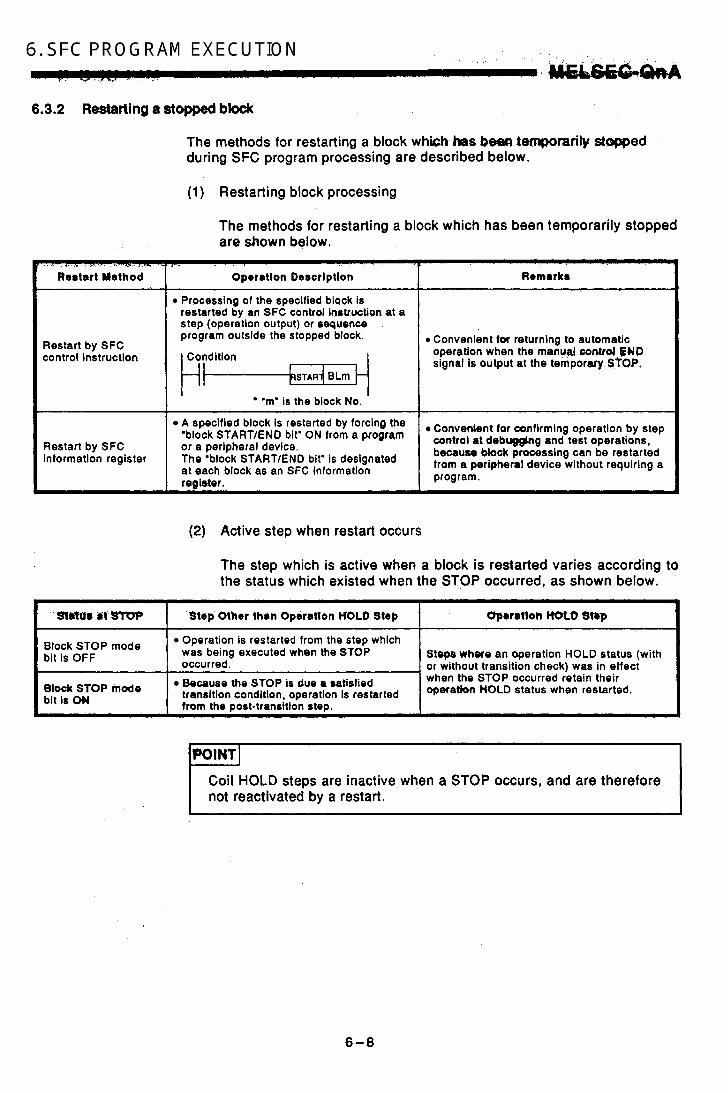
6. SFC PROGRAM .. EXECUTION . . 1 . , . . f
6.3.2 Restarting a stopped blodc
Ma&&&-
The methods for restarting a block whkh has been temporarily s t w e d during SFC program processing are described below.
(1) Restarting block processing
The methods for restarting a block which has been temporarily stopped are shown below.
Restart Method
Restart by SFC control instruction
Oporrtion Descriptlon
Processing of the specified block is restarted by an SFC control inntruction at a step (operation output) or sequence program outside the stopped block.
Condition
Remrrkr
Convenient for returning to automatic operation when the manual contrd SWD signal is output at the temporary STOP.
i I 'm' is the block No.
A spec'fied block is restarted by the
program. register. at each block as an SFC information
because Mock processing can be restarted a device without requiring a The 'block STARTlEND bit' is designated information register
control et debugging and test operations, 'block START/END bit' ON from a prqr4m or a peripheral device. Restart by SFC
Convenient for confirming operation by step
(2) Active step when restart occurs
The step which is active when a block is restarted varies according to the status which existed when the STOP occurred, as shown below.
' s m f t . Z I s T O p Operatlok HOLD Slbp Stap Other than Oprra?lon HOLD Step
Block STOP mode bit is OFF
e,ock mode bit is ON
Because the STOP is due a satisfied
Operation is restarted from the step which was being executed when the STOP
or without transition check) was in effect occurred. Steps where an operation HOLD status (with
from the post-transitlon step. operation 'OLD status when restarted. transition condition, operation is restarted when the STOP occurred retain their
!POINT I 1
I Coil HOLD steps are inactive when a STOP occurs, and are therefore not reactivated by a restart.
6-8

. . 6.4 Step START (Activate) and END (Deactivate) Methods I ' . . ' , : . . , . , ' . , C f
6.4.1: ' -:=ART-*)- I
The methods for activating steps are described below.
,
Step START (Acthrata) Yathod
Step START by SFC diagram symbol
(1) Step START (activate) methods
Steps can be started (activated) by the methods shown below.
OparrUon Dmcrlptlon Ramark8
The step is automaticallystarted (activated) when the preceding trnnsition con(ntibnis satisUld.
Condition
TRAN
condition is satisfied.
~~
Basic SFC program aperatlon
D Using an 6FC control instrucllon, a $podfled step Is forcibly sbrted from' an SFC program step (operation output), or hom another sequence program.
t - l l
'n' is the step No. Condition
%I* is the block No., 'n' is the step No.
Jumps to otborbhck are possible. I f the block where the specified destination step is located is inactive, a forced block START wUI occur. When multiple Initial steps exist, a selection START will occur.
. , L
Step START by SFC control instruction
(2) . Operation at double step START
When a double step START occurs for a step which is already active, operation varies according to the.START method as shown below. (a) Double START by SFC diagram symbol
Operation varies according to the "tran&ion to active step" block parameter setting for the block in question.
When "PAUSE" setting is designated ........................ A CPU operation error occurs, and
CPU operation is stopped. When 'WAIT" setting is designated ........................ The previous step is deactivated
and a WAIT status is established. The transition occurs when the transition destination step becomes inactive. (Transition destination step is reactivated.)
6-8

6. SFC PROGRAM EXECUTION . , , , . .=- A
, -.
0 When “TRANSFER” setting is desigcwbd . . . . , . . . . . , . . . , . . . , . . . . . The transition occurs immediately,
and the previous step is deactivated. (The activation is ab,sorbed.)
(b) Double START by SFC control instruction The instruction is ignored, and processing of the START destination step continues as is. (The instruction is executed in the same way as the NOP instruction.)

6.4.2 Step END (deactiwm)metWds
- 7-4 '
Step END Method , .
END by SFC diagram symbol
END by SFC control instruction
The methods for deactivating steps are described below.
(1) Steps can be ended (deactivated) by the methods shown below.
~. . ~ ~ .~
Operation Dorcriptlon
The step is automat~cal'ty deacthrated by the system when the step's transition condition is satisfied.
If a reset step is designated as the step attribute, the reset (deactivate) step No. must be specified.
t
Using an SFC control instruction, a specified step is forcibly reset (deactivated) from an SFC program step (operation output), or from another sequence program.
t i t Condition
'n' is the step No. . Condition
'm. is the block No., 'n' is the step No.
Remarks
Basic SFC program operation At steps where attributes are specified, operation will occur according to the attribute.
Convenient for resetting HOLD steps during SFC program execution when a machine operation condition is satisfied, or when a parallel branch transition to an error processing step occurs.
the same block. The specified reset step must be located in
Step resets at other blocks are also possible. I f all the block's steps are deactivated by the reset, processing of that block will be ended.
L
c
4

6. SFC PROGRAM EXECUTION w w . .
6.4.3 Changing an active step status
The method for deactivating an active step and aetiiating a specified step is shown below.
ohmgo "hod
Change by SFC c0nCol instruction
Opwation Dewtip4Ion
Active SFC program steps (instruction execution steps) are deactivated, and a forced START is executed for a specified step.
Active step deactivated 3 Specified step
is activated
.. -
6-12
Remarks
Convenient when jump &stinatton vades according to the condition. The change destination step must be located tmthe cwnrnt block. Indirect designation ( 0 0 , K4M0, etc.) of the change destination step is also possible. If multiple instructions exist in a single step, the change destination executed in the same scan will be effective.

APPENDICES , :
APREbl~4~S-S SPEGl,AL W Y ANP.SMClAL.REGISTER U T
The special relays and special registers which can be used in SFC pro- gfams m.*-.., For information regarding dhw special rdgcs and special registers (not used at'SFC program), refer to the QnACPU Programming Manual (Com- mon Instructions).
1.1 'SM" Sljecfal Relays
No. Name
SMO Diagnosis error
I Step transition SMg0 watchdog timer START (corresponds
to SD901 Step transition
START (corresponds
START (corresponds to SD92) Step transition watchdog timer START (corresponds to SD93) Step transition watchdog timer START (corresponds to SD94) Step transition
SM95 watchdog timer START (corresponds to SD951
SM93
SM94
I
Step transition
START (corresponds
START (corresponds
I I SteD transition
START (corresponds
I' Step transition watchdog timer START (corresponds to SD99)
SM99
Content
OFF: normal (no error) ON : abnormal (error)
OFF: Watchdog timer
ON : Watchdog timer reset
START
Doscrlptbn
Switches ON when a diagnosis result error occurs. (Also switches ON at ah external diagnosis error.)
is restored. rn Remains ON even whan normal status
Switched ON to begin the step transition watchdog timer count. Watchdog timer is reset when switched OFF.
APP - 1
OWOFF Control
System (at error
Dccurrence)
User

APPENDICES - - No.
3M32Q
SM321
sM322
SM323
SM324
SM325
-
Name .I Content
1 OFF: SFC program
SFC program ON : SFC program STARTISTOP
STOP
START
SFC program START status : ReMImptive
OFF: Initial START
START
OFF: Continuaw All-blocks continuous
ON : Continuous transition status transition enabled
transition disabled
Continuous transition disable flag
OFF: After transition ON : Before transition
Operation output at block STOP
OFF: Coil output OFF ON : Coil output ON
Dercrlptlon
D Switches ON when the SFC program status is normal, with the parameter prograin setttngs'dedgnated.
Switches ON automatically when an
I f switched OFF by another program file SFC program Is prosent.
prior to SFC program execution, the SFC program will not be executed. SFC program STARTlSTOP control is possible by ONlOFF switching at the USW program.
designated at the parameter's SFC program START mode. When OFF: All execution statuses are
The default value is the value
cleared when the SFC proqbm is stoppod; and a START occurs from the initial step of block 0 .
When ON : A START occurs from the blodc and step which were being executed when the SFC program was stopped.
i An 'ON' settingis only valid when the parameter's SFC program START mode Is set to 'resumptive START".
When the transition conditions of contigums steps are all satisfied, this setting determines whether all those steps will be executed in a single scan. When ON : Continuous e x w t i o n
(contlnuous transition enabled)
1 -step-per-scan format (continuous transition disabled)
When OFF: Steps are executed in a
I When the SFC information register's 'continuous transition bit' setting is designated at each block, those settings will take precedence.
I f the continuous transition status is set to ON, this flag is ON until the continuous transition occurs, and switches OFF when a 1-step transition is completed. A continuous transition for the step in question can be prevented by designating an AND condition for SM324. Designates the operation output which occurs when the block Is stopped. When ON : The coil output ONlOFF
status at the step being executed when the block is stopped is maintained (HOLD).
When OFF: All coil outputs are switched OFF.
(Operation outputs which occur in response to the SET instruction are maintained (HOLD) without regard to the SM325 ONIOFF status.) -
OWOFF Conbot
System
value) (intttal
System (initial value),
User
System (initial value),
User
User
System (for
instruction execution)
System (initial value),
User

I ( '
Content I -. Destrlptlon 1
sMBis ,' stored:dIt(##ll6 and 50817.
completOd2kWin SFC program. ' . 0FF:.D4pbWL''.: .' 'Status &# SFC Svvllcheo Oh 'wheh status check is System
change) infotmation WIU9tV8WitChBd ON, hformlrtbn is ' ' . ON : h q b l M , . ( s 4 h
I 1 . . .. .I
SM820 Step trace ready status I - I OFF: .Nkm ON : Ready
t , , ; :: .. I
I I ' , .
1' I "
! ,%-
Switches ON when a 'ready' status is es~bl isbed&ter&ep . , . trace registration.
Designata the stap trace S T A R n s K l P status. When ON : Step trace function is
started. When OFF: Step tram function is
stopped. i f switched OFF during a trace execution, the trace operation is stopped.
System (status
change)
User
SM822 Step trace wecution ON when step trace execution is in System progress, and OFF when tracing is (status ampleted or stepped. change) flag, ON : Trace active
. . SwitchsS bN when a trigger condition is System
step trace function is being executed. change) SM823 Post-triggar OFF' unsatisfied satisfied at any of the blocks where the (status ON : Trigger satisfied
Switches ON when trigger conditions are satisfied at all blocks where the step trace function is being executed.
Switches ON when step tracing is completed at all the specified blocks, and switches OFF when step tracing beains.
System (status
change)
System (status
change)
' . . -:.i . .
Am.-3
/
i b
I
/
h - ,
i
L
i
,
I

APPENDICES . . ,... / . . , ' ' ..,,.. , t - . .
1.2 'SD" SpWaI Registers -+
- No. -
SDO
-
SD 1
SD3 to
-
SD4
-
SD5
SD15 to
Name
Diagnosis error
Time of diagnosis error occurrence
Error information classification
Error 'common information'
Diagnosis error No.
Time of diagnosis wror occurrence
Error information classification code
Error 'common information'
Omription
1 The No. of the diagnosis error is stored as 4-digit binary
1 When more than one error has occuned, the error with the hiohmst disPlaY Drioritv is stored.
1 The clock data when an SDO update occurs is stored.
,D3 Minute (0 to 59)ISecond (0 to 59
Code which identifies an error as 'information' or 'individual information. is stored.
bl!j - - - - - - b8 b7- - - - - - bo
(BIN 8 bits) : (BIN 8 bits)
I L- 'Common information' codes
0 : None 1 : Unit No. 2: File name
'Individual information' codes
0 : None 1 : 3: Time (senkrg vatue) 2: File name 3: Time (actual count value) 4: Program error location 5: Parameter No. 6: Annunciator F No. 7: CHK instruction Failure No.
4: Program error location
The error 'common information' is stored. When the SFC program is started, data is stored as follows:
File name
SD8
Extend name b 1 5 - - b3 b2 bl bO
SO1 1
SD12 bO ... SFC Mock information
bl:..SFC sten information prese,nt
1 ~ ~ c ~ ~ n I b2 ... SFC transition present '
condition information present

No. I Name
W0.treOcHlpn watchdog timer
SD91 setting
SM911 (corresponding to
(corresponding to sM9-2) Step,-traMbh watchdog timer
SD93 setting
sM931 (corresponding to
Step transition watchdog timer
SM941 (corresponding to
SD94 w w :
SO95
SD96
Step transitbn watchdog timer setting '. (Eonwpadiing to SMQS) Step transition watchdog timer setting (corresponding to S M96 ) Step transition watchdog timer
SD97 setting (kwresponding to SM971
SD98
SD99
Step transition watchdog timer setting (corresponding to SM98) Step transition watchdog timer settine (corresponding to S W )
SD816 . Stat.ui check execution block No.
5081 7 Status check cutecMbm step No.
Content
, 1. , ,
Timer setting value and 'F' Na. at time- over
Status check exeaution bbxk No.
S W S & e h t i o n stop. No.
, ' .. . . I ... , . n _,,.
b Tbmz.:'0dluUUd- There is no 'i4qiyieal information' fox sups originating _ .
: -.,,.. ,".. . *, ... . d , ~ ..
at-SFC programs.
rn The step transition watchdog timer's setting value, and the OF' No. which switches ON when a watchdog timer time- over status occurs are designated.
115 t i b8 b7 t i bo,
Timer limit setting (1 to 255 secb.; designated in 1-sec. units)
OF' NO. setnng
The timer is started when any of these special registers switches ON. I f the next transition condition for the step in question is not satisfied within the designated time, the specified annunciator (F) switches ON.
0 The block No. where a status check (at SFC program) is executed is stored.
Valid onlv when SM816 is ON. The step No. where a status check (at SFC program) is executed is stored.
Valid only when SM816 is ON.
I

c-
._ -
APPENDICES . .
APPENDICES 2 MELSAP-II AND MELSAPB C O M P A S H M
Compared tu MELSAP-tl., the'impraved MELSAP3 bas' adUltlanaf'funHions which facilitate the use 61 9PC programs. MELSAP-II aM"ELSAP3 are compared below.
MELSAP3 improvements and added functions (a) SFC program control by instructions
Using SFC control instructions at a sequence program; the SFG '
program status can be checked, and blockdsteiji can be forcibly started and ended.
possible SFC programs can be expressed as ladders or IMs, and step and transition condition programs (timer (T) and counter (C) setting values, etc.) can be revised at the Q6PU.
MELSAP3 offers many more step attributes, such as the operation HOLD step, reset step, block START step (without END wait), etc. Moreover, machine control by SFC program has been made eas- ier by improvements such as the step follow-up function (activates, multiple steps in a series within a single block), and a control func- tion which allows transitions (at block START requests) without waiting for a block END status at the START destination block (asynchronous control of the START source and destination blocks).
In addition to an increased number of steps and branches per block, the capacity of step and transition condition programs has been increased to 4k sequence steps in order to make program- ming easier.
The amount ot .bbk infotmatlon has been increased, permitting operations such as a contlnqtws transition designation in 1 -block units, and a STOP timing se!ed,ion fimmed,iate, STOP". 01 "STOP when transition condition is satisfied") for block STOP requests. Furthermore, the additional block information simplifies operation by permitting a block START and END to be executed from a sin- gle device.
The SFC program's system processing time has been reduced, resulting in reduced tact times through the efficient combination of the SFC program functions.
Troublesome menu switching operations have been eliminated by permitting SFC comments, steps and transition condition pro- grams to be created concurrently with SFC ladder creation. Moreover, the SFC diagram cut & paste function, and block unit registrationhtilization have been simplified.
(b) Expression of SFC program as a sequence program (tadderllist) i s
(c) Additional step attributes
(d) Expanded memory capacity
(e) Substantial blwk information
(1) Increased processing speed reduces system processing time
(9) Improved operability of SFC software package
For reference purposes, comparisons of the major MELSAP-II and I MELSAP3 functions are shown in the following pages. I

Operation HOLD step (with transition check)
Reaet rtep . , . I
Block START step (with END wait) Block START step (without END, wait)
~ - ~-
a
I
Coupling 8 Branch
' , YELSAPS
o n
IRI
I
P? I
Coupling and branch duplications are possible at a transition condition.

APPENDICES
(2) SFC 'Controt Instructions
The SFC control instruction shown below are available at MELSAP3. MELSAP-It has no SFC control instructions.
Name Wder Exprors,lon 1 Functlon
.1
'inactive) check LD AND OR nstruction
. Executes 8 Oheck to determine i f a specified step at a specified block is active or inactive.
( mi. u c l : mi) B L ~ -
f LDl, MI: oRi) T R ~ LD, AND OR Checks a specified step in a specified block
Forced transition check transition control hetruction) for that step mstruction (0 determlno i f the hansltbn condition (by . was satistied forcibiy or nut. LD, AND OR ( LDI. ANI,' OR;) BLn\TRn
Block operation status active or inactive. [ LDI. ANI, ORI] BLm check instruction Checks a specified block to determine i f It Is LD. AND, OR,
MOV (P) K4Sn (Dl
MOV (P) BLm\K4Sn (D)
.1
Active steps batch readout instruction
DMOV (P) Active steps in a specified block are read to a
DMOV (P)
BMOV (P)
BMOV (P) BLm\K4Sn (D) Kn
specified device as bit information.
A specified block is forcibly started Block START instruction (activated) independently, and is executed SET BLm
from its initial step.
Block END instruction RST BLm A specified block is forcibly ended (dsactivated).
Block STOP instruction I PAUSE BLm I A specified block is temporarily stopped.
The temporary stop status at a specified Block restart instruction block is canceled, with operation resuming RSTART B Lm
from the STOP step.
(activated) independently, and is executed from a specified step.
SET Sn
SET BLm\Sn
0 A specified block is forcibly started
Step control instruction RST Sn ~~
. l A specified step at a specified block is
RST BLm\Sn forcibly deactivated.
The instruction execution step is deactivated, O 2 I and a soecified step is activated.
SET TRmn .1 - A specified transition condition at a specified
Transition control instruction
SET BLm\TRn block is forcibly satisfied.
RST TRn
RST BLm\TRJl
BRSET (D)
.1 The forced transition at a specified transition condition in a specified block is canceled.
Block switching instruction instruction are designated.
Blocks subject to the "1'SFC control
When the instruction execution condition is Subroutine call instruction XCALL Pn
ON, the subroutine call is executed In a constant manner. When switched OFF, the subroutine call occurs oniv once at that time.
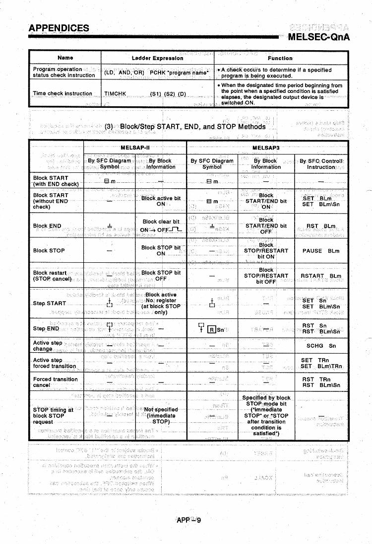

APPENDICES . . . ~ . . .-. . MELSEGOnA
(4) SFC Program Specifications
SFC program
ttam MELSAPI MELSAP-II
Capacity Max. 58K bytes (A3N, A3A, A3U, A4U) Max. 124K bytes (main program only) (Q4ACPU)
-
Number of blocks Max. 320 blocks Max. 256 blocks I I
Number of SFC steps Max. of 255 steps per block Max. of 81 92 steps (total for all blocks),
max. of 51 2 steps per block
Number of branches Max. of 32 Max. of 22
Max. of f280 steps Number of
max. of 22 steps per block concurrently active (total for all blocks), Max. of 1024 steps (total for all blocks),
steps) block (including HOLD steps max. of 256 steps per
Number of operation Max. of 255 sequence steps output sequence steps block, no limit per step I I M a r of 4k steps per
Number of transition condition sequence stem
Max. of 255 sequence steps Max. of 4k steps per block, no limit per step
Step transition watchdog timer function Function exists (8 timers) I Function exists (1 0 timers)
(5) System Processing Times for CPU Types
Item I MELSAP-II MELSAPO 1
AOACPU (F) AOUCPU A4UCPU I AnNCPU-F
AlSCPU Q4ACPU QOACPU
Active block processing I 57.0 pS I 260.0 pS I 20.3 pS I 40.5 ps I Inactive block processing I 14.0 pS I 45.0 pS I 4.0 pS I 7.9 pS I
~~ ~ -~~
Nonexistent block processing
14.7 ps 7.4 ps 100.0 ps 29.5 pS at active step Processing of transition condition
6.3 pS 3.2 pS 355.0 pS 49.5 ps Active step processing
4.1 pS 2.1 ps 25.0 pS 4.0 pS
Processing Of step step designation 17.0 pS 60.0 pS 7.8 pS 15.6 pS with satisfied transition condition With HOLD step 2.4 pS 13.5 pS 2.1 ps 4.2 pS
28.5 pS 14.3 j . 6 28.5 pS
195.0 pS 97.5 ps 195.0 pS
Without HOLD
designation With 'initial START' With 'resumptlve START'
SFC END processing 285.0 pS
APP - 10

