safety and procedures for gas handling for the borexino
TRANSCRIPT
Safety and Procedures for gas handling for the Borexino Source Insertion system. April 9, 2006 Steve Hardy Athans Hatzikoutelis Jonathan Hughes Matthew Joyce Steve Kidner Raju Raghavan R. Bruce Vogelaar Overview This system is designed to allow a source (or optical fiber) to be inserted anywhere within the inner detector and located to within +/- 2 cm. The sources are small quartz spheres similar to those used in the CTF. The insertion mechanism consists of several neutrally buoyant rigid rods that are subsequently coupled together. One section has a hinge, which allows for motion off-axis. The off-axis motion is accomplished by pulling on a ¼” Teflon tube ‘tether’ which will swing the lower rod sections off to one side. The azimuthal position is set by rotating the rod assembly. Care must be taken to not rotate the rod by more than +/- 180 degrees to avoid twisting the tether around the rod. Since mechanical indexing using this method is not precise, an LED is attached near the source which, when lit, can be imaged using the seven cameras mounted on the SSS. Tests have shown that the HV for the phototubes does not need to be turned off during this process. An unusual difficulty arises since the natural PC level in CR4 is set by the filling stations to be about 2 meters above the floor of CR4. To accommodate this, a load-lock method is employed to ensure the ambient pressure above the PC liquid is always sufficient to keep the liquid level from rising. This means that both the insertion rods and the Teflon ‘tether’ tube must pass through sliding seals. The actual level of the PC only needs to be maintained to about +/- 10 cm, even though the pressure in the vessels is regulated much more precisely. This is because the density of the gas above the liquid level is a factor of 1000 less than the liquid. Radon and other gases are prevented from contacting the liquid by means of a glove-box which provides a first-order protection (it’s not hermetic), and ultimately by the sliding seals. The seal around the rod is also purged since there are voids within the rod couplings which make continuous sealing impossible. Since one must couple the ‘tether’ and the rod together below the sliding seals, there is an access cross which acts as a load-lock. This cross is evacuated multiple times, and then backfilled to the required pressure with “low Ar and Kr Nitrogen (LAKN)” before the gate-valve to the inner vessel is opened.

The coupling of the tether tube to the rod end is complicated since the angle between the two depends upon the hinge position. The primary mechanical termination is a pre-compressed Swagelok ferrule which registers into a mating groove in the split coupling (see diagram below). Secondary mechanical coupling is by means of a spring (whose upper end is captured and has a detent that registers and locks the spring into position) and a chemical bond. There are three different tubes which can be used, each with a unique purpose. 1) Fiber optic: sealed by quartz/Teflon bond; 2) normal radioactive source: tube sealed by quartz/Teflon bond; 3) PC collection tube: unsealed, transverse pin through tube as secondary stop. The principle concerns are cleanliness, failure modes where PC would rise into this region, gross overpressure, inadvertent light leakage, inability to retract source due to tangling, and source breakage. Cleanliness is addressed in several fashions. First, the system resides in a Class 10 clean room (CR4) and second the rods are stored within the glove-box after a final cleaning. The glove-box provides an ambient LAKN atmosphere, and has large, conductive, acrylic side plates for viewing. The PC should only be exposed to LAKN using the load-lock system described above. Contaminants on the surface of the inserted components (<2m2) which have perhaps built up are removed by a final acid rinse close to the time of being used. The efficacy of these procedures could in principle be tested in the CTF. Rn emanation from the gaskets is removed by the constant purging of the cross during operation. Whenever the gate-valve to the IV (v1320) is open, valves to the IV (v1321) and IB (v1421) filling stations are closed. The displaced volume (< 20 liters) due to the rod insertion is compensated by the OB filling station operation. However, this means that should pressure in the cross be lost, even though interlocks turn off the OB make-up pump, the volume of the OB header tank could flow into this region. To prevent this, the glass windows are provided with back-up sealed acrylic windows. Likewise, the insertion rod to source coupler has a mechanical stop to prevent it from being accidentally withdrawn completely from the sliding seal, and the ‘tether’ sliding seal has an alternative plug which can be inserted should the tube fail. The ‘tether’ tube itself sometimes could have PC in it (PC collection mode), so it rises to a level above the header tanks before connecting to the laser or other device. There is also a catch basin in CR4. Gross overpressure is avoided by means of a pressure relief valve on the cross, whose operation is tested prior to each insertion. No serious consequences of an overpressure would occur until the liquid level was forced down to the top of the inner vessel. Light leakage is only a concern during the initial and final passage of the source past the gate-valve separating the calibration system from the IV (v1320) when the small viewing ports are uncovered to allow visual inspection. During this time CR4 will only be illuminated by red light. Another possible light leak is presented by the Teflon ‘tether’ tube, which needs to be evaluated by further tests. The liquid-alarm system has a ‘sweep-
arm’ which can be used to insure that there is nothing blocking the gate-valve, meaning that the gate-valve could in principle be closed without the visual inspection step. Possible tangling of the source is minimized by procedures that prohibit the turning of the source system by more than +/- 180 degrees. Rotational alignment is mechanically assured by the method of coupling rods together. Also, the hinge on the source rod can only bend 90 degrees before reaching a mechanical stop. It is also designed to have no protruding edges that could get caught at any steps in the upper pipes. Careful inventory of lengths of rod and tether, coupled with LED imaging, should allow us to keep track of what is going on inside. Should a problem develop, the HV could be turned off and normal photographs inside the SSS will help resolve questions. The excess tube is stored in the glove box side top-hat in alternating right- and left-handed loops to prevent twisting. To help maintain tube orientation and length measurements, it is a clear Teflon which allows one to see fiducial marks within it. The insertion length is also determined with a roller meter. The scintillator sampling tube needs to be clean on the inside, so it will only be used on the vertical axis. Since the insertion rods are neutrally buoyant, only the small additional weight where the source is mounted is available to pull the tether back down when one tries to return the source to the vertical axis. Should this not prove enough, one can actually use the vessel itself to provide a downward force by allowing the source to touch the vessel. Since the lever arm of this contact greatly exceeds that available from the central 4” pipe, and the source is spring mounted, this should not pose undue danger to the vessel (during the CTF operations, the source was also brought into contact with the vessel in this fashion). Each rod will be weighed before and after insertion to check for any possible leaks. The possibility of source breakage is minimized by spring-mounting of the source, and the fact that the source insertion rod is a larger diameter than the source itself. The source is held by the quartz itself, to not stress the quartz-metal seal which is part of the source containment vessel. We are cognizant that sources were both broken (while still above the IV gate valve) and actually dropped into the CTF during the early CTF campaigns. The current design and procedures have been modified to minimize the chances of any such accident. This document provides only a cursory summary of numerous details that have been incorporated into this design, but should provide a reasonable introduction into the issues relating to mechanical and environmental safety of the Borexino detector. The camera control software is integrated with source moving procedures to make logging simple and accurate. Only trained personnel will be allowed to use the source insertion system and camera locating system. Since CR4 potentially has PC fumes in it, extra steps have been taken to eliminate sources of ignition. It should be noted, however, that being a class 10 cleanroom, the

one-pass air exchange in CR4 is very large, so we do not anticipate any fumes to accumulate. Within the glovebox, there will be some PC fumes as source rods are withdrawn, but there is no oxygen present for combustion. Never-the-less, within the glove box there are only two electronic elements: a hermetically sealed strain gauge, and a fully enclosed optical switch. All the control valves and pumps are located in a separate box on the side of the glove-box which is actively purged with air, whose flow is interlocked. If this flow is interrupted, power to the gas control box is disconnected via relays external to CR4. The valves are normally closed with power failure. On the following pages are short descriptions of major components. Following that is a schematic of the gas-flow equipment and then individual flow diagrams for major operations. The major hardware components and their specifications are found in the accompanying “hardware.xls” and “part-specs.pdf” files. Procedures are defined in the accompanying “procedures.xls” file. You can use “View” “Custom Views” in Excel to see predefined views.

Basic configuration. The gloves for the glove box are not shown. The walls are clear plastic. Sealing is accomplished by a rubber gasket, one side covered with Cu tape. This is not truly hermetic, but creates the first level of Rn reduction in the area, and provides mechanical separation for cleanliness. The cut-away view is taken with a plane at the centerline. Notice that the hinged rod is being displayed which accounts for the obvious bend. The top-hat, which projects into the ceiling of CR4, allows the rods to be extracted sufficient distance to be decoupled. All the flanges of the cross are rotateable conflat. The two flanges with conflat windows (and sealed protective covers) are viton sealed to allow easier changing of sources. The cross is continuously purged at a well-regulated pressure, to prevent Rn emanation contamination from the seals. The tether pillbox is designed to ensure that coils do not slip past eachother since they alternate between right- and left-handed loops. Short manual augers feed loops on/off as needed. Box mounts on top of SSS fill tube, and is decoupled mechanically from CR4 for earthquake considerations.

This provides an image of the sliding seals. Compression is provided by three clamps. The rod seal is purged with LAKN at a pressure equal to that within the cross. Thus the pressure gradient across the lower seals is zero during rod and tube adjustment. The o-rings between the seals and the baseplate are not displayed, although the grooves are there. The upper gray ring around the rod is a split Delrin ring used to lock the rod’s insertion depth and orientation. The tether tube sliding seal has a large hole in the baseplate to allow objects mounted to the Teflon tube, but of larger diameter, to be removed. The Teflon tether tube is not displayed.
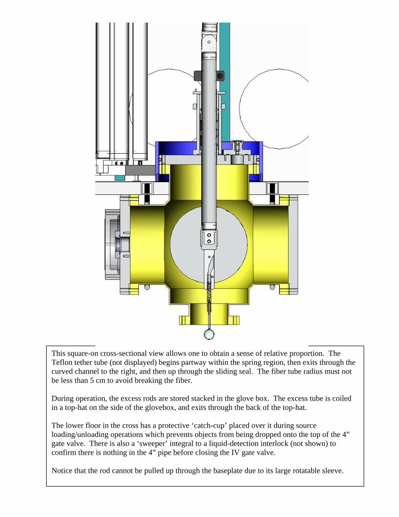
This square-on cross-sectional view allows one to obtain a sense of relative proportion. The Teflon tether tube (not displayed) begins partway within the spring region, then exits through the curved channel to the right, and then up through the sliding seal. The fiber tube radius must not be less than 5 cm to avoid breaking the fiber. During operation, the excess rods are stored stacked in the glove box. The excess tube is coiled in a top-hat on the side of the glovebox, and exits through the back of the top-hat. The lower floor in the cross has a protective ‘catch-cup’ placed over it during source loading/unloading operations which prevents objects from being dropped onto the top of the 4” gate valve. There is also a ‘sweeper’ integral to a liquid-detection interlock (not shown) to confirm there is nothing in the 4” pipe before closing the IV gate valve. Notice that the rod cannot be pulled up through the baseplate due to its large rotatable sleeve.
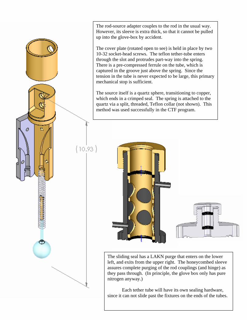
The rod-source adapter couples to the rod in the usual way. However, its sleeve is extra thick, so that it cannot be pulled up into the glove-box by accident. The cover plate (rotated open to see) is held in place by two 10-32 socket-head screws. The teflon tether-tube enters through the slot and protrudes part-way into the spring. There is a pre-compressed ferrule on the tube, which is captured in the groove just above the spring. Since the tension in the tube is never expected to be large, this primary mechanical stop is sufficient. The source itself is a quartz sphere, transitioning to copper, which ends in a crimped seal. The spring is attached to the quartz via a split, threaded, Teflon collar (not shown). This method was used successfully in the CTF program.
The sliding seal has a LAKN purge that enters on the lower left, and exits from the upper right. The honeycombed sleeve assures complete purging of the rod couplings (and hinge) as they pass through. (In principle, the glove box only has pure nitrogen anyway.) Each tether tube will have its own sealing hardware, since it can not slide past the fixtures on the ends of the tubes.
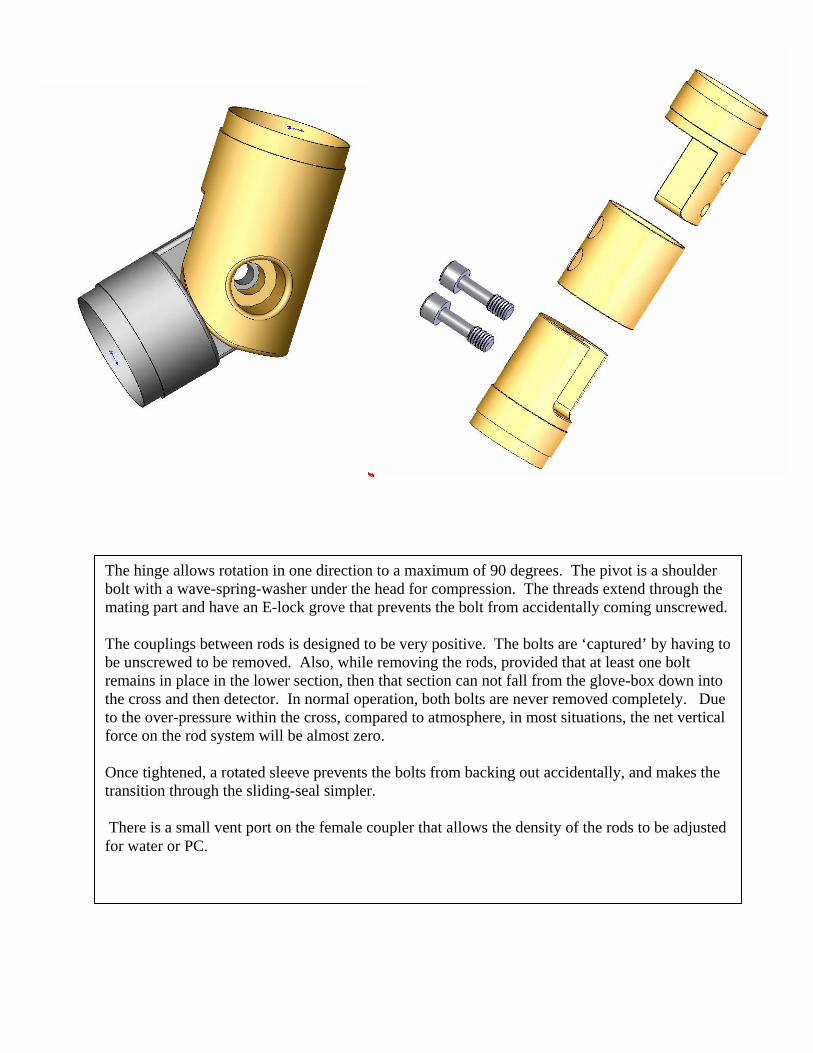
The hinge allows rotation in one direction to a maximum of 90 degrees. The pivot is a shoulder bolt with a wave-spring-washer under the head for compression. The threads extend through the mating part and have an E-lock grove that prevents the bolt from accidentally coming unscrewed. The couplings between rods is designed to be very positive. The bolts are ‘captured’ by having to be unscrewed to be removed. Also, while removing the rods, provided that at least one bolt remains in place in the lower section, then that section can not fall from the glove-box down into the cross and then detector. In normal operation, both bolts are never removed completely. Due to the over-pressure within the cross, compared to atmosphere, in most situations, the net vertical force on the rod system will be almost zero. Once tightened, a rotated sleeve prevents the bolts from backing out accidentally, and makes the transition through the sliding-seal simpler. There is a small vent port on the female coupler that allows the density of the rods to be adjusted for water or PC.

Tether storage top-hat. The two augers are to keep the coils in order. The tether is stored in alternating loops − right handed and left-handed − to keep there from being a net twist. There are three such storage bins, one for each type of tether. The ID is 12” , and the back plane is Lucite, providing excellent visibility.
Tether metering device. It uses a small optical switch, and is only 4.5” in overall length. There are two springs (not shown) which provide tension between the axles. The wire connection will be potted in epoxy at the bottom of the above diagram. The four holes in the measuring wheel have graded gray films in them, so that CW motion gives 1:2:3:4, while CCW motion gives 4:3:2:1.
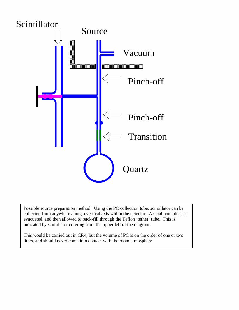
Transition
Pinch-off
Pinch-off
Source
Vacuum
Scintillator
Quartz
Possible source preparation method. Using the PC collection tube, scintillator can be collected from anywhere along a vertical axis within the detector. A small container is evacuated, and then allowed to back-fill through the Teflon ‘tether’ tube. This is indicated by scintillator entering from the upper left of the diagram. This would be carried out in CR4, but the volume of PC is on the order of one or two liters, and should never come into contact with the room atmosphere.

Preliminary fiber optic light source. The quartz housing allows the UV light to propagate several centimeters before being absorbed by the pseudocumene, thus minimizing self-shielding. The Teflon tube for Borexino will be 17 m long and used to pull sources off the vertical axis by actuating a hinge in the insertion rod. This prototype for the CTF does not have the pre-compressed ferrule, required by the new design.

glove box
cross
rods F1
to charcoal filter
V1320 CV4
G2
G3
G5
G6
FS
P1
P2 OM
F2
F3
F4
VM1
VM2
VM3
TM
LC(1-4)
L7
L6
L4
L3
L1
L12
L11
L10
L9
L8
L13
V1
V2
V3
V5
V4
V7
V6
slip lock
C1
C2
hinge
retraction stop
source
¼” Teflon tube
V8
to PC waste
CV3
G4 L5
April 14, 2006
LAKN
V1377
L2
R1
R2
R3
CV1
G1
L14
AFM
Fan and wiring to computer
Overall gas flow schematic.
CV2
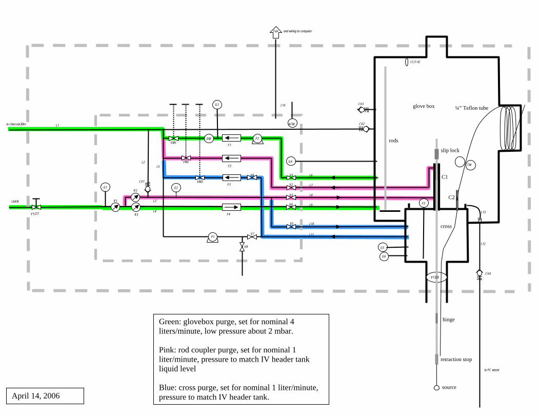
Green: glovebox purge, set for nominal 4 liters/minute, low pressure about 2 mbar. Pink: rod coupler purge, set for nominal 1 liter/minute, pressure to match IV header tank liquid level Blue: cross purge, set for nominal 1 liter/minute, pressure to match IV header tank.
glove box
cross
rods F1
to charcoal filter
V1320 CV4
G2
G3
G5
G6
FS
P1
P2 OM
F2
F3
F4
VM1
VM2
VM3
TM
LC(1-4)
L7
L6
L4
L3
L1
L12
L11
L10
L9
L8
L13
V1
V2
V3
V5
V4
V7
V6
slip lock
C1
C2
hinge
retraction stop
source
¼” Teflon tube
V8
to PC waste
CV3
G4 L5
April 14, 2006
LAKN
V1377
L2
R1
R2
R3
CV1
G1
L14
AFM
Fan and wiring to computer
CV2
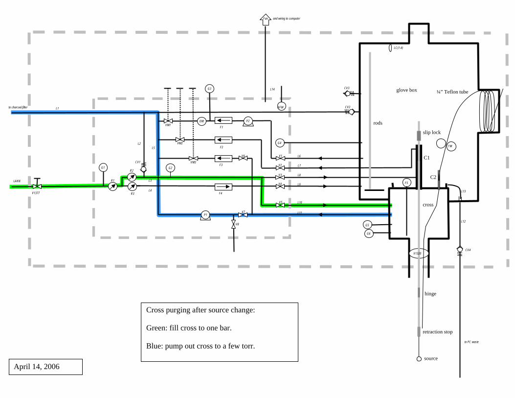
Cross purging after source change: Green: fill cross to one bar. Blue: pump out cross to a few torr.
glove box
cross
rods F1
to charcoal filter
V1320 CV4
G2
G3
G5
G6
FS
P1
P2 OM
F2
F3
F4
VM1
VM2
VM3
TM
LC(1-4)
L7
L6
L4
L3
L1
L12
L11
L10
L9
L8
L13
V1
V2
V3
V5
V4
V7
V6
slip lock
C1
C2
hinge
retraction stop
source
¼” Teflon tube
V8
to PC waste
CV3
G4 L5
April 14, 2006
LAKN
V1377
L2
R1
R2
R3
CV1
G1
L14
AFM
Fan and wiring to computer
CV2
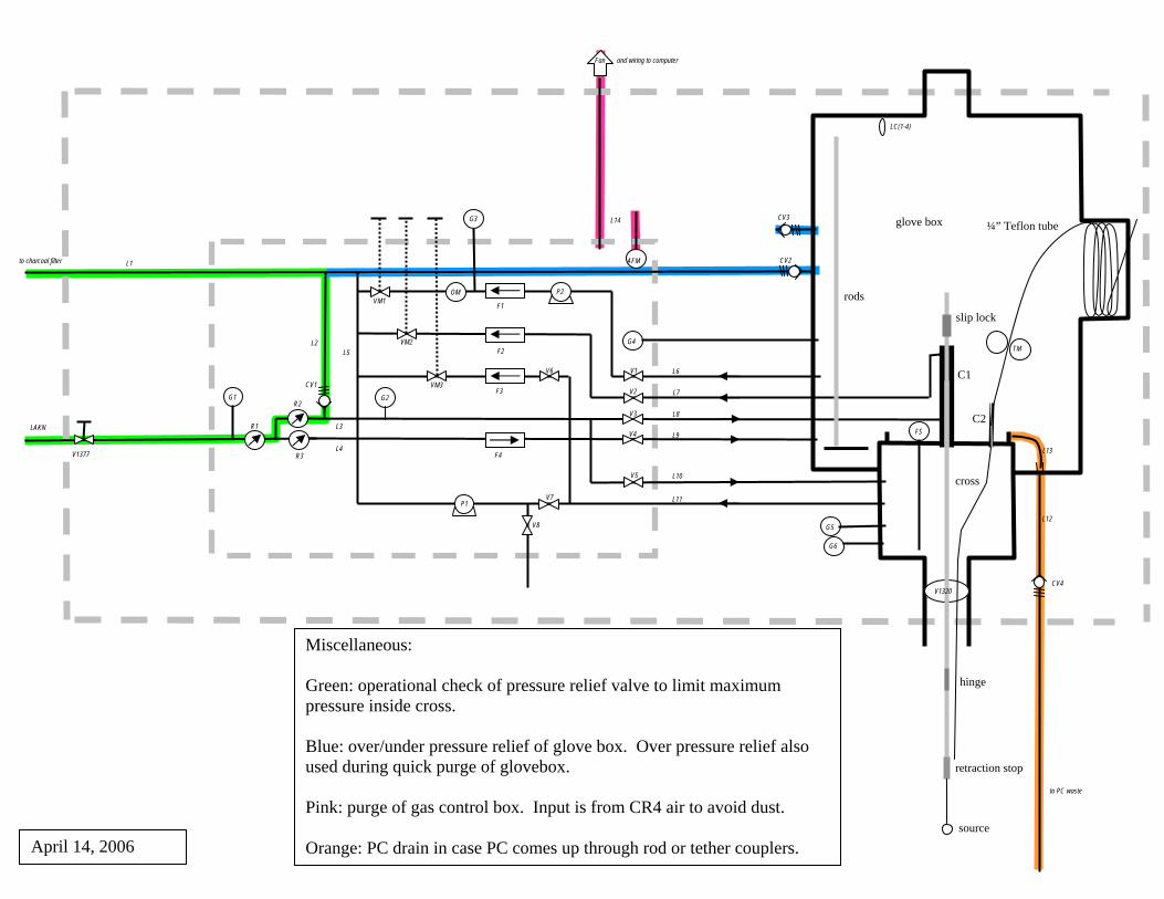
Miscellaneous: Green: operational check of pressure relief valve to limit maximum pressure inside cross. Blue: over/under pressure relief of glove box. Over pressure relief also used during quick purge of glovebox. Pink: purge of gas control box. Input is from CR4 air to avoid dust. Orange: PC drain in case PC comes up through rod or tether couplers.
glove box
cross
rods F1
to charcoal filter
V1320 CV4
G2
G3
G5
G6
FS
P1
P2 OM
F2
F3
F4
VM1
VM2
VM3
TM
LC(1-4)
L7
L6
L4
L3
L1
L12
L11
L10
L9
L8
L13
V1
V2
V3
V5
V4
V7
V6
slip lock
C1
C2
hinge
retraction stop
source
¼” Teflon tube
V8
to PC waste
CV3
G4 L5
April 14, 2006
LAKN
V1377
L2
R1
R2
R3
CV1
G1
L14
AFM
Fan and wiring to computer
CV2