safety advice: precautions against electrostatic ignitions...
TRANSCRIPT
Shell Global Solutions
Shell Research Ltd., Cheshire Innovation Park, P.O. Box 1, Chester CH1 3SH, England. Tel: +44 (0) 151 373 5000
Registered in England No. 539964, Registered Office: Shell Centre, London SE1 7NA
Shell Global Solutions is a trading style used by a network of technology companies of the Royal Dutch/Shell Group
Shell Global Solutions (UK) is a division of Shell Research Ltd.
OG.02.42373
Safety Advice: Precautions against electrostatic ignitions when loading vehicles with bulk fuels
H.L.Walmsley
June 2003
SHELL GLOBAL SOLUTIONS (UK)
Fuels Business Group

OG.02.42373
iii
Contents
1 Introduction, Purpose and Scope............................................................................................ 1 2 Managing the risk of electrostatic ignition when loading road tankers .............................. 2
2.1 Plant requirements.............................................................................................................. 2 2.2 Vehicle requirements.......................................................................................................... 3 2.3 Assurance ........................................................................................................................... 4 2.4 Loading velocity for uncontaminated liquids..................................................................... 5
2.4.1 Method for determining the loading velocity (flow chart) ......................................... 5 2.4.2 Classifying flammability, product conductivity and sulphur content ......................... 7
2.5 Loading velocity for contaminated liquids....................................................................... 10 2.6 Loading procedures .......................................................................................................... 10 2.7 Meter proving................................................................................................................... 10 2.8 People............................................................................................................................... 11
3 Managing the risk of electrostatic ignition when loading rail tankers .............................. 12 3.1 Road/rail differences ........................................................................................................ 12 3.2 Plant requirements............................................................................................................ 12 3.3 Rail track .......................................................................................................................... 12 3.4 Tank car requirements ...................................................................................................... 12 3.5 Loading velocity for uncontaminated liquids................................................................... 13
3.5.1 Method for determining the loading velocity (flow chart) ....................................... 13 3.6 Loading velocity for contaminated liquids....................................................................... 14 3.7 Loading procedures .......................................................................................................... 14 3.8 Meter proving................................................................................................................... 14 3.9 People............................................................................................................................... 14
4 Managing the risk of electrostatic ignition when loading ships or barges ........................ 15 4.1 Background ...................................................................................................................... 15 4.2 Minimum precautions for all products ............................................................................. 15 4.3 Precautions for low conductivity (<50 pS/m) products.................................................... 17 4.4 Other considerations......................................................................................................... 17
4.4.1 Ship/shore insulating, earthing and bonding ........................................................... 17 4.4.2 Ship/shore bonding cables ....................................................................................... 17 4.4.3 Insulating flanges/hose-strings ................................................................................ 17 4.4.4 Inert gas systems ...................................................................................................... 18 4.4.5 Portable equipment .................................................................................................. 18
5 Other containers..................................................................................................................... 19

OG.02.42373
iv
5.1 Small containers (<50 l) and buckets ............................................................................... 19 5.2 Intermediate bulk containers (IBCs) ................................................................................ 19
5.2.1 All metal IBCs .......................................................................................................... 19 5.2.2 IBCs made of non-conductive material with a conductive enclosure ...................... 20 5.2.3 IBCs made of non-conductive material .................................................................... 20
6 Information for 3rd parties or exchange partners .............................................................. 21 Appendix A: Site-specific rules example 1; small site................................................................ 23
A.1 Site Details ........................................................................................................................... 23 A.2 Plant requirements................................................................................................................ 23 A.3 Vehicle requirements............................................................................................................ 23 A.4 Assurance ............................................................................................................................. 24 A.5 Loading velocity for uncontaminated liquids....................................................................... 24 A.6 Loading velocity for contaminated liquids........................................................................... 24 A.7 Loading procedures .............................................................................................................. 24 A.8 Meter proving into a truck via a portable meter prover........................................................ 25 A.9 Small containers (<50 l) and buckets ................................................................................... 25 A.10 People ................................................................................................................................. 25
Appendix B: Site-specific rules example 2; large site ................................................................ 27 B.1 Site Details............................................................................................................................ 27 B.2 Common requirements for all loading points ....................................................................... 27
B.2.1 Plant requirements......................................................................................................... 27 B.2.2 Vehicle requirements ..................................................................................................... 28 B.2.3 Assurance....................................................................................................................... 28 B.2.4 Loading velocity for contaminated liquids .................................................................... 28 B.2.5 Loading procedures: bonding........................................................................................ 28 B.2.6 Meter proving ................................................................................................................ 28 B.2.7 Small containers (<50 l) and buckets ............................................................................ 29 B.2.8 People ............................................................................................................................ 29
B.3 Additional specific requirements for particular loading points: ........................................... 29 B.3.1 Gasoline loading rate .................................................................................................... 29 B.3.2 Low sulphur diesel: bottom loading .............................................................................. 29 B.3.4 Other kerosene, diesel and gasoil: legacy top loading.................................................. 30 B.3.5 Other kerosene diesel and gasoil: bottom loading ........................................................ 31
Appendix C: Site-specific rules example 3; dedicated vehicles ................................................. 33 C.1 Site Details............................................................................................................................ 33 C.2 Common requirements for all loading points ....................................................................... 33
C.2.1 Plant requirements ........................................................................................................ 33 C.2.2 Vehicle requirements ..................................................................................................... 33 C.2.3 Assurance ...................................................................................................................... 34
OG.02.42373
v
C.2.4 Loading procedures: bonding. ...................................................................................... 34 C.2.5 Meter proving ................................................................................................................ 34 C.2.6 Small containers (<50 l) and buckets............................................................................ 34 C.2.7 People ............................................................................................................................. 35
C.3 Loading rates ........................................................................................................................ 35 C.3.1 Relevant loading conditions .......................................................................................... 35 C.3.2 Normal loading velocity ................................................................................................ 35 C.3.3 Loading velocity for contaminated liquids ..................................................................... 35
Appendix D: Procedure to measure the conductivity of gasoils................................................ 37 D.1 In–situ measurements ........................................................................................................... 37 D.2 Measurements on samples.................................................................................................... 37 D.3 In line measurements............................................................................................................ 38
Appendix E: Conductivity meters: which types and how to use............................................... 39 E.1. Introduction ...................................................................................................................... 39 E.2. Emcee conductivity meter ................................................................................................ 39
E.2.1 Calibration...................................................................................................................... 39 E.2.2 Procedure for measuring conductivity of samples.......................................................... 40 E.2.3 Re-calibration and servicing ......................................................................................... 40 E.2.4 Storage of meters ........................................................................................................... 40
E.3. Maihak Conductivity Meter, (Type MLA)....................................................................... 40 E.3.1 Meter calibration ........................................................................................................... 41 E.3.2 Cleaning the cells........................................................................................................... 41 E.3.3 Procedure for measuring conductivity in-situ ............................................................... 41 E.3.4 Re-calibration and servicing ......................................................................................... 42 E.3.4 Storage of meters ........................................................................................................... 42
Appendix F: Recording and analysing conductivity monitoring data ..................................... 43 F.1 Record sheet for monitoring storage tanks............................................................................. 43 F.2 Control charts......................................................................................................................... 43
Appendix G: Procedures for adding static dissipator additive to gasoils ................................ 45 G.1 General ................................................................................................................................. 45
G.1.1 Static Dissipator Additive (SDA): grade to be used....................................................... 45 G.1.2 Preparation of stock solution ......................................................................................... 45
G.2 Process for conductivity checking and additivation .............................................................. 45 Appendix H: Risk factors ............................................................................................................. 51
H.1 General .................................................................................................................................. 51 H.2 Liquid properties .................................................................................................................. 51
H.2.1 Conductivity ................................................................................................................... 51 H.2.2 Sulphur content............................................................................................................... 51 H.2.3 Vapour pressure ............................................................................................................. 51
OG.02.42373
vi
H.2.4 Wetness........................................................................................................................... 52 H.3 Loading system...................................................................................................................... 52
H.3.1 Loading speed ............................................................................................................... 52 H.3.2 Presence of vapour: VRU connections.......................................................................... 52 H.3.2 Filtration ....................................................................................................................... 52
H.4 Vehicle factors...................................................................................................................... 52 H.4.1 Presence of vapour........................................................................................................ 52 H.4.2 Compartment size .......................................................................................................... 52 H.4.3 Compartment shape....................................................................................................... 53 H.4.4 Splash loading ............................................................................................................... 54
H.5 Ambient conditions ............................................................................................................... 55 H.5.1 Temperature ................................................................................................................... 55 H.5.2 Humidity ......................................................................................................................... 56
H.6 People and clothing ............................................................................................................... 56 Appendix I: Additional information............................................................................................ 57
I.1 High speed loading compartments.......................................................................................... 57 I.2 Placement of filters ................................................................................................................. 57 I.3 Earthing................................................................................................................................... 58 I.4 Loading arms, top-loading and splash filling.......................................................................... 58 I.5 vd limits................................................................................................................................... 59
I.5.1 How vd limits arose ......................................................................................................... 59 I.5.2 Background to vd limits for particular operations .......................................................... 59
Appendix J: Flow rate tables and vd equivalents ....................................................................... 63 Appendix K : Plastic materials ..................................................................................................... 67
K.1 Definitions............................................................................................................................. 67 K.2 Size Limits............................................................................................................................. 67
Appendix L: Contacts ................................................................................................................... 69

OG.02.42373
vii
Foreword
When vehicles are loaded with petroleum products there is often a flammable atmosphere in the compartment vapour space. The product flows associated with loading cause the generation of electrostatic charges. This charging is very variable and unless the charges are carefully controlled, sparks may occasionally occur that are capable of ignite any flammable atmosphere that may be present. In the petroleum industry worldwide, the inadequate control of static electricity during loading operations leads every year to serious accidents resulting in death, injury or major equipment damage.
This Safety Advice describes the procedures needed to control static electricity in vehicle loading operations. It is aimed primarily at terminal managers and others with responsibility for the safe conduct of loading operations. Secondary targets are engineers and system designers. Additional technical information more relevant to these groups is given in the later Appendices.
Although the document is long, it need not be read from cover to cover. For example, the essential precautions for road tanker loading are covered in just 8 pages. The rest of the document covers other types of loading, provides non-essential background information (useful for system designers) or offers simplified guidance for specific situations. A full contents list is provided so readers can identify and concentrate on the sections relevant to their own operations.
It is important that the relevant sections of the Advice are understood and followed because the consequences of failing to control static electricity are severe.

OG.02.42373
1
Safety Advice: Precautions against electrostatic ignitions when
loading vehicles with bulk fuels
1 Introduction, Purpose and Scope
This Safety Advice gives the current Shell mandatory requirements for controlling the risk of electrostatic ignitions during vehicle loading operations. It supersedes Safety Advice Document OP.98.42197 and the relevant sections of the Shell Safety Committee publication "Static Electricity - Technical and Safety Aspects" (June 1988). The Advice is aimed primarily at Terminal/Depot Managers and others responsible for supervising loading activities although the later Appendices give explanatory background and additional technical information on risk factors and loading rates that is likely to be of most use to system designers and engineers.
Common loading procedures have recently been agreed between the major oil companies and are now incorporated into industry (IP, EUROPIA) and international (CENELEC, ISGOTT) standards or codes of practice1. With the exception of the road tanker loading rates recommended for gasoline2, this Safety Advice is compatible with these codes and standards. It applies to:
• All flammable petroleum products except aviation fuels. Aviation fuels have distinct quality and handling requirements that are the responsibility of Shell Aviation.
• The loading of road and rail tankers at refineries, terminals and depots,
• Filling product into, or receiving product from, ships or barges at these facilities and
• The use of IBCs for flammable products.
The main text (Sections 2, 3, 4 and 5) gives general operating rules for the above activities with a minimum of explanation. These rules are designed to cover all operational circumstances. For the specific operations at a particular site, it is often possible to define simpler rules that are easier to understand and follow than the general rules (e.g. barge loading need not be covered if only road loading occurs). Appendices A to C give simplified operating rules for three specific site situations. These may be used instead of the more general rules if the specified situations match local conditions. Shell Global Solutions could assist in drawing up alternative simplified advice if required for different sets of specific site conditions.
The remaining Appendices give detailed procedures for conductivity measurement and re-doping with Static Dissipator Additive in addition to the background information mentioned in the first paragraph.
1 Work on the CENELEC standard is still in progress. When complete, the CENELEC document is likely to replace the Shell Safety Committee publication "Static Electricity - Technical and Safety Aspects" (June 1998) as the underlying basis for static electricity safety recommendations within the Shell Group 2 We are trying to get the rates advocated for gasoline in this Safety Advice accepted by CENELEC.
OG.02.42373
2
2 Managing the risk of electrostatic ignition when loading road tankers
2.1 Plant requirements • General earthing or bonding:
All pipes in the loading system must be conductive.
There must be electrical contact between all components of the liquid handling system (pipework, filters, metering, loading arm or hose) and the metalwork of the loading system structure. Where there is direct metal-to-metal contact between a component and the loading system structure (e.g. via flanged joints, bolted or welded brackets etc.) the resistance to the structure must be less than 10 Ω. Where there is not continuous metal-to-metal contact (e.g. across greased swivel joints or with non-metallic pipes) the resistance must be less than 1 MΩ. These levels of resistance will normally be provided inherently by the construction of the system but it may be necessary to provide specific bonding links.
• Swivel joints Generally, swivel joints have a low enough resistance (<1 MΩ) but some greases can be highly insulating and electrical continuity across swivel joints needs to be checked annually or if the grease is changed. Checks should be done for several positions of each joint because the resistance can vary. If continuity over a swivel joint is inadequate, the resistance can be reduced by changing to more conductive grease or by providing a bonding link across the joint.
• Hoses: Flexible hoses are normally used for bottom loading. They must not be used for top loading unless the tanker vehicle is fitted with fill tubes reaching the base of the compartment to avoid splash loading. Flexible hoses used for loading must meet the required standards for fuel hoses including either the conductive or dissipative resistance standards. Conductive hoses must have a resistance of less than 10 Ω and Dissipative hoses must have a resistance per unit length of less than 1 MΩ/m. The condition of hoses must be checked visually every 3 months and the end-to-end (i.e. coupling to coupling) resistance must be measured every 6 months. Both these checks must also be done if the hose may have been damaged (e.g. if it has been run over). Conductive hoses must be discarded if there is a break or any obvious permanent distortion of the external helix or if the end-to-end resistance increases by more than 30%. Dissipative hoses must be discarded if there is obvious damage or if the resistance per unit length exceeds 1 MΩ/m.
• Drop-tubes on top-loading arms: For most top-filling applications (see Footnote3 for exceptions), the drop-tube must be metal and must be long enough to reach the base of all compartments that might be loaded. There should be a tee-piece on the end of the drop-tube to deflect the flow along the base of the compartment. The tee-piece should preferably be made of a dissipative rubber to avoid mechanical damage. Filter socks (as sometimes used for conductive solvents such as alcohols) must not be used on the end of loading arms for hydrocarbon fuels (see Appendix I.2). It is
3 The usual long-tube requirement is for cases where there could be a flammable atmosphere. It may be permissible to use a short drop tube to splash-load flammable liquids of low volatility (e.g. luboils) that are incapable of producing a flammable vapour atmosphere at the maximum handling temperature. However with this approach it is essential that there is no switch-loading, no other possible source of flammable vapour and that the loading process does not produce enough mist or suspended droplets to render the atmosphere flammable.
OG.02.42373
3
particularly important that the drop tube meets the general earthing or bonding requirements outlined above. Where drop tubes are removable from the loading arms, e.g. with camlock fittings, adequate electrical contact across the joint must be established and checked each time the arm is re-connected.
• Plastic materials
Plastic materials can be classified by their electrical resistivity as non-conductive (insulating), dissipative or (rarely) conductive. Definitions are given in Appendix K. The use of dissipative or conductive plastics does not generally give rise to concerns arising from static electricity but the use of insulating plastics needs to be carefully controlled.
o As a general principle, the use of insulating plastics should avoided in hazardous areas including those around vehicle loading points. Despite this they may be acceptable in locations where they would not be subject to any electrostatic charging.
o Within hazardous areas and where the materials could be subjected to electrostatic charging (most commonly by the flow of product but also, possibly, by rubbing) either:
The maximum area of plastic must not exceed the values given in Appendix K or
A larger area may be used provided it is subdivided by a mesh or grid of earthed, conductive or dissipative material on or near the surface. In this case the maximum area enclosed by any cell of the mesh must be less than four times the limits given in Appendix K4.
2.2 Vehicle requirements 1) Bonding of vehicle components:
The resistance between the chassis, the tank and the associated pipes and fittings on the truck must be less than 10 Ω. Pipework should generally be conductive but plastic vapour lines are acceptable.
2) Vehicle type: Where high-speed loading is used (see Section 2.4), it is necessary to verify that each vehicle loaded is suitable for this practice. Table 1 gives a definition of “suitable for high-speed loading” that is valid for ADR5 compliant vehicles. A more general definition is given in Appendix I6. If a vehicle is not ADR compliant, a detailed assessment based on the general definition must be carried out before it can be classified as suitable for High Speed Loading. The designation of a compartment as suitable or unsuitable for high speed loading supersedes the old distinctions between top loading and bottom loading and between bottom loading with and without a central conductor7. Top-loading vehicles must be treated as not suitable for high-speed loading unless a documented risk assessment has been carried out and effective procedures are in place to:
a) ensure that no top-loading vehicles are splash filled and
b) prevent loose items being dropped into the compartment during loading.
4 Larger areas can be tolerated for subdivided sheets because the presence of the earthed mesh holds potentials lower than for a completely isolated piece of plastic of the same size. 5 Accord European Relatif au Transport International des Marchandises Dangereuses par Route, abbreviated to Accord Dangereuse Routiers and usually referred to as 'ADR' 6 See also Appendix H (Sections H.4.2 and H.4.3) for an explanation of the influence of the compartment structure. 7 The new definitions have been introduced partly because they recognize that there are more ways of reducing potentials in a compartment than having a central conductor and partly because it was not possible to obtain general agreement about the relative safety of top and bottom loading.
OG.02.42373
4
Procedures that allow top-loading vehicles to be considered suitable for high-speed loading are given in Appendix H (Section H.4.4) and Appendix B gives an application example. If there is any doubt about the adequacy of procedures and, in particular, about whether the site can guarantee full and vertical insertion of top-loading arms on all occasions, top-loading vehicles must be considered as not suitable for high-speed loading.
3) Compartments clear of debris Conductive debris (cans, buckets or even smaller items such as tools) inside truck compartments can promote electrostatic discharges. It is therefore essential to ensure before loading that all compartments are clear of such debris.
4) Dipsticks Dipsticks should be made of a partly conductive (dissipative) material. The cheapest alternative is wood, which performs well if it has been properly treated to prevent absorption and creep. A suitable example is Canadian Hard Rock Maple, kiln dried to 10 – 12% moisture content and treated with several coats of aniline dye. Slightly more expensive is Glass Reinforced Plastic (GRP) which has a small amount of carbon added to achieve the desired resistivity.
Table 1 ADR compliant vehicles suitable for high speed loading
Vehicle If a vehicle/tanker is to be classed as suitable for High Speed Loading, then all compartments on that vehicle must be High Speed Loading Compartments.
High Speed Loading Compartment
A High Speed Loading Compartment is any compartment, or Chamber, with a capacity ≥ 2,000 l and ≤ 15,000 l equipped with a conductor which is either a) a full height baffle or surge plate, or b) an Internal Tube, or c) a Central Conductor Wire, so that no part of the liquid, in plan view, is >0.8 m from any conducting surface. Larger compartment sizes do not require such a conductor to be classed as High Speed Loading Compartments.
Where a compartment is fitted with an overfill, or other, probe which is ≥ 0.5 m from a "conductor", as defined above, the probe must be fitted with a "probe extender" to be fixed to the probe and located at the floor of the compartment.
Central Conductor
An electrically continuous cable/wire with a diameter ≥ 2 mm and ≤ 10 mm, or ≥ 50 mm, fixed to the roof of the compartment or chamber and located at the floor. The cable/wire must be of stainless steel and have sufficient mechanical integrity to resist normal wear and tear.
Internal Tube Any tube for dipping, service or vapour recovery which is electrically continuous with the shell of a compartment or chamber.
Chamber A chamber is the space created in a compartment larger than 7,500 l when that compartment is subdivided by baffles or surge plates, in accordance with the ADR,, into spaces of smaller capacity.
Footvalve for bottom loading
Bottom-filling arrangements can tend to produce an upwardly directed liquid jet (e.g. because of the location of the footvalve in a well in the base of the tank). For a high-speed loading vehicle, these upward jets must be prevented using a deflector plate if necessary.
2.3 Assurance Programmes of routine monitoring, including pre-loading checks and technical audit on plant and trucks must be used to ensure that the requirements in Sections 2.1 and 2.2 are met.
OG.02.42373
5
2.4 Loading velocity for uncontaminated liquids8
2.4.1 Method for determining the loading velocity (flow chart) The velocity or loading rate at each loading point must be set so that it cannot exceed a limit derived from the flammability of the vapour, the conductivity and sulphur content of the product and the type of vehicle being loaded. The flow chart in Figure 1 shows how to decide the velocity limit for distillate-loading operations with uncontaminated liquids. The limits are expressed in terms of the maximum permissible vd value where vd is the product of the flow velocity, v, in m/s and the pipe diameter, d, in m. The flow rates and velocities corresponding to the vd limits are given in Appendix J for a range of standard pipe diameters.
To derive a vd limit using the flow chart in Figure 1 it is necessary to:
a) Determine whether a flammable atmosphere could occur (over rich atmospheres are considered potentially flammable) and if so whether it is usually too rich (e.g. when loading gasoline).
b) Decide whether any trucks not suitable for high-speed loading could be filled.
c) Classify the product conductivity (≤10 pS/m, ≤50 pS/m, >50 pS/m) or treat it as unknown.
d) (For middle distillates only) Classify the sulphur content (≤50 mg/kg, >50 mg/kg).
Truck classification is covered in Section 2.2, Table 1. The other classifications are covered in Section 2.4.2. Once an appropriate vd limit has been found it should be used along with the pipe diameter and the flow rate tables in Appendix J to determine the maximum permissible flow velocity and volumetric flow rate. The pipe diameter used for this stage of the calculation should normally be the smallest diameter upstream of the loading point. It is, however, acceptable to disregard short sections of reduced diameter provided the diameter of the reduced section is at least 2/3 that of the rest of the line and the reduced section is less than 5 m long.
If there are circumstances in which a higher than normal risk is perceived (e.g. if the melting of winter ice produces an increased risk of water in the system), then additional precautions should be taken such as reducing vd limits below the standard values in Figure 1 or raising the conductivity with SDA. The extra precautions should be used for both middle distillates and gasolines.
8 Contaminated liquids are mixtures of substantially different products or liquids that contain gross amounts of free water or dirt (more than 0.5%v free water or more than 10 mg/l of suspended solids). All other liquids can be regarded as uncontaminated. If a system is, for any reason, expected to be prone to contamination or wetness, it maybe advisable to introduce additional safety measures (e.g. raise the conductivity with SDA or reduce the vd limit below the value specified in Flowchart 1).
OG.02.42373
6
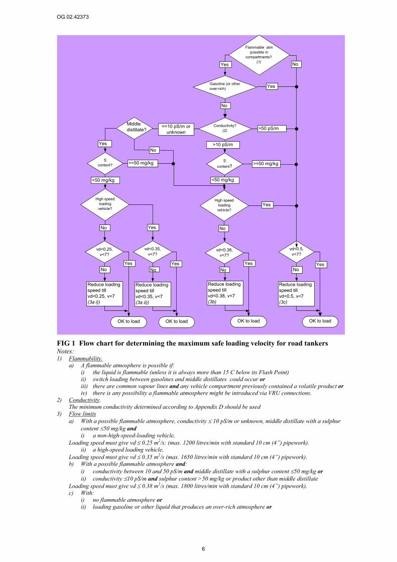
FIG 1 Flow chart for determining the maximum safe loading velocity for road tankers Notes: 1) Flammability.
a) A flammable atmosphere is possible if: i) the liquid is flammable (unless it is always more than 15 C below its Flash Point) ii) switch loading between gasolines and middle distillates could occur or iii) there are common vapour lines and any vehicle compartment previously contained a volatile product or iv) there is any possibility a flammable atmosphere might be introduced via VRU connections.
2) Conductivity. The minimum conductivity determined according to Appendix D should be used
3) Flow limits a) With a possible flammable atmosphere, conductivity ≤ 10 pS/m or unknown, middle distillate with a sulphur
content ≤50 mg/kg and i) a non-high-speed-loading vehicle,
Loading speed must give vd ≤ 0.25 m2/s; (max. 1200 litres/min with standard 10 cm (4”) pipework). ii) a high-speed loading vehicle,
Loading speed must give vd ≤ 0.35 m2/s (max. 1650 litres/min with standard 10 cm (4”) pipework). b) With a possible flammable atmosphere and:
i) conductivity between 10 and 50 pS/m and middle distillate with a sulphur content ≤50 mg/kg or ii) conductivity ≤10 pS/m and sulphur content >50 mg/kg or product other than middle distillate
Loading speed must give vd ≤ 0.38 m2/s (max. 1800 litres/min with standard 10 cm (4”) pipework). c) With:
i) no flammable atmosphere or ii) loading gasoline or other liquid that produces an over-rich atmosphere or
Gasoline (or other over-rich)
Flammable atm possible in
compartments? (1)
vd<0.5,v<7?
Conductivity?(2)
Reduce loading speed till vd<0.5, v<7(3c)
S content?
High speed loading vehicle?
OK to loadOK to load
S content?
High speed loading vehicle?
vd<0.38,v<7?
vd<0.35,v<7?
vd<0.25,v<7?
Reduce loading speed till vd<0.38, v<7(3b)
Reduce loading speed till vd<0.35, v<7(3a ii))
Reduce loading speed till vd<0.25, v<7(3a i))
OK to loadOK to load
>50 pS/m
>10 pS/m
>=50 mg/kg >=50 mg/kg
<50 mg/kg <50 mg/kg
Yes
Yes
No No
Yes Yes YesYesNo No No No
Yes No
Middle distillate?
YesNo
=<10 pS/m or unknown
Yes
No
OG.02.42373
7
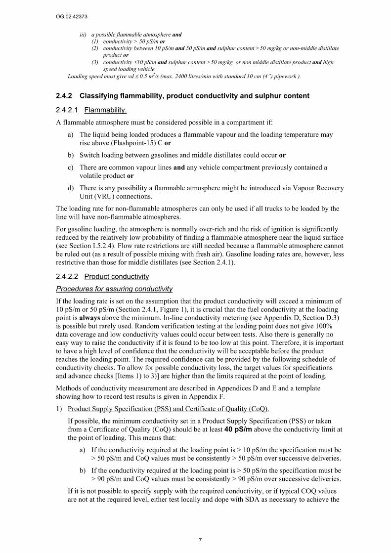
iii) a possible flammable atmosphere and (1) conductivity > 50 pS/m or (2) conductivity between 10 pS/m and 50 pS/m and sulphur content >50 mg/kg or non-middle distillate
product or (3) conductivity ≤10 pS/m and sulphur content >50 mg/kg or non middle distillate product and high
speed loading vehicle Loading speed must give vd ≤ 0.5 m2/s (max. 2400 litres/min with standard 10 cm (4”) pipework ).
2.4.2 Classifying flammability, product conductivity and sulphur content
2.4.2.1 Flammability. A flammable atmosphere must be considered possible in a compartment if:
a) The liquid being loaded produces a flammable vapour and the loading temperature may rise above (Flashpoint-15) C or
b) Switch loading between gasolines and middle distillates could occur or
c) There are common vapour lines and any vehicle compartment previously contained a volatile product or
d) There is any possibility a flammable atmosphere might be introduced via Vapour Recovery Unit (VRU) connections.
The loading rate for non-flammable atmospheres can only be used if all trucks to be loaded by the line will have non-flammable atmospheres.
For gasoline loading, the atmosphere is normally over-rich and the risk of ignition is significantly reduced by the relatively low probability of finding a flammable atmosphere near the liquid surface (see Section I.5.2.4). Flow rate restrictions are still needed because a flammable atmosphere cannot be ruled out (as a result of possible mixing with fresh air). Gasoline loading rates are, however, less restrictive than those for middle distillates (see Section 2.4.1).
2.4.2.2 Product conductivity
Procedures for assuring conductivity If the loading rate is set on the assumption that the product conductivity will exceed a minimum of 10 pS/m or 50 pS/m (Section 2.4.1, Figure 1), it is crucial that the fuel conductivity at the loading point is always above the minimum. In-line conductivity metering (see Appendix D, Section D.3) is possible but rarely used. Random verification testing at the loading point does not give 100% data coverage and low conductivity values could occur between tests. Also there is generally no easy way to raise the conductivity if it is found to be too low at this point. Therefore, it is important to have a high level of confidence that the conductivity will be acceptable before the product reaches the loading point. The required confidence can be provided by the following schedule of conductivity checks. To allow for possible conductivity loss, the target values for specifications and advance checks [Items 1) to 3)] are higher than the limits required at the point of loading.
Methods of conductivity measurement are described in Appendices D and E and a template showing how to record test results is given in Appendix F.
1) Product Supply Specification (PSS) and Certificate of Quality (CoQ).
If possible, the minimum conductivity set in a Product Supply Specification (PSS) or taken from a Certificate of Quality (CoQ) should be at least 40 pS/m above the conductivity limit at the point of loading. This means that:
a) If the conductivity required at the loading point is > 10 pS/m the specification must be > 50 pS/m and CoQ values must be consistently > 50 pS/m over successive deliveries.
b) If the conductivity required at the loading point is > 50 pS/m the specification must be > 90 pS/m and CoQ values must be consistently > 90 pS/m over successive deliveries.
If it is not possible to specify supply with the required conductivity, or if typical COQ values are not at the required level, either test locally and dope with SDA as necessary to achieve the

OG.02.42373
8
required conductivity (see Items 2) and 3) below) or change the operating conditions until the loading rate is appropriate for the conductivity supplied (e.g. reduce the flow rate or use a vehicle suitable for high speed loading, see Figure 1 for details). The normal loading rates should be set so that changes are needed only under exceptional circumstances.
2) Pre-delivery monitoring.
Where possible, monitor the conductivity of every batch immediately prior to accepting delivery at the facility. At this stage the conductivity should have a margin of at least 30 pS/m above the conductivity required at the loading point. Thus:
a) If the conductivity required at the loading point is > 10 pS/m the target value is 40 pS/m.
b) If the conductivity required at the loading point is > 50 pS/m the target value is 80 pS/m.
If the conductivity falls below the target value, adjust it, if possible, by re-doping with SDA (see Appendix G) before receipt into the facility tanks9. If the conductivity cannot be adjusted before receipt, re-measure as soon as possible after receipt and carry out adjustment if necessary and possible [as in Item 3) below]. The need for re-doping may be minimised or eliminated altogether by receiving into tanks that already contain high conductivity product. This approach may be particularly useful if there are no facilities for mixing the product once it is in tankage.
If successive delivery parcels show major conductivity variations there is a risk that future values might fall below the target and the facility manager should give feedback to the supplier.
3) Monitoring in facility tankage.
Monitor the conductivity of product in tankage at the facility (or at the refinery for refinery-based loading facilities fed directly from the refinery). At this stage, the conductivity should have a margin of at least 20 pS/m above the conductivity required at the point of loading. Thus:
a) If the conductivity required at the point of loading is > 10 pS/m the target value is 30 pS/m.
b) If the conductivity required at the point of loading is > 50 pS/m the target value is 70 pS/m.
If the measured conductivity falls below the target value adjust it, if possible, by re-doping with SDA in the facility tankage (see below and Appendix G) and re-check. If re-doping is not possible (e.g. if there is no means mixing the additive), the loading velocity at all loading points fed from the tank must be reduced to a value compatible with the measured conductivity. The normal loading rate should be set so that changes to the operating conditions are needed only under exceptional circumstances. Initially, conductivity monitoring in tankage10 should be done for every fuel batch. Subsequently, if the absence of excessive depletion between the pre-delivery conductivity and the conductivity in tankage has been demonstrated (e.g. by the use of a reliable database of conductivity measurements as described below), it may be possible to reduce the frequency of conductivity monitoring in tankage. However, spot checks are still recommended and, whenever checking prior to receipt is not possible, the conductivity of every batch should be checked in tankage as soon as possible after receipt and recorded as part of the batch release
9 For example, with marine deliveries, conductivity checks should be made and any necessary re-doping carried out in the ship's tanks before discharge. 10 Initially this should be done even when the conductivity has been monitored prior to receipt in order to allow for losses during the transfer into tankage.

OG.02.42373
9
procedure. Checking in tankage should also be done whenever there is any reason (e.g. maintenance activities, installation of new pipework, suspected contact with unusually high amounts of water) for concern about a possible change in the level of depletion.
4) Verification checks at the point of loading.
Perform random conductivity verification checks at the loading point. Initially there should be one test per batch of fuel but the testing frequency may be reduced with confidence in the prior data and a reliable history of verification checks. Ultimately, these checks can be done less frequently than those in tankage. Validation checks must be carried out at the coldest time of normal operations (i.e. early morning or night). If it is not possible to sample at the loading point, a high level of confidence in the conductivity provision is essential and multiple advance checks, as outlined above, have to be conducted and recorded. Post-loading checks involving samples taken from the truck after loading are also recommended.
If the conductivity measured in a verification-check falls below the required minimum, the loading rate must be reduced to a level that is acceptable for the measured conductivity. Loading velocities must be reduced in this way at all loading points for that batch of fuel. Loading at normal speeds must not recommence until conductivity monitoring, both in tankage and at the loading point, has shown that the conductivity is back up to the required level. Because altering the flow rate is often not practical, all effort must be directed to avoiding this situation by careful checks before the product gets to the loading point.
Use of a reliable measurement database to reduce measurement frequency As indicated above, the frequency of measurement both in tankage and at the gantry may be reduced if both the following conditions are met:
a) There is a sound database of combined conductivity and temperature data indicating both:
i. That for this grade and source of product, the conductivity at the gantry, in the facility tankage and on delivery has been consistently above the required levels over a substantial period of time, a relevant range of ambient temperatures and with a consistently high degree of confidence in data accuracy.
ii. The absence of excessive depletion between the upstream location and the measurement point in question.
b) There have been no changes due to new installation, modified distribution path, maintenance activities or increased contact with water that might lead to increased levels of additive depletion.
Any plan for reduced measurement frequency must include at least one measurement (pre-delivery or in tankage) on each batch of fuel.
Combined conductivity and temperature data is essential for building a sound database. The frequency of testing should be restored to its original level if there is a substantial change in product grade or supply route or any known disturbance to the supply chain. The use of control charts (see SMS 1006-91) may provide significant benefits in establishing the reliability of the conductivity supply.
2.4.2.3 Sulphur content The sulphur content can be taken from the maximum value in the product specification. If there is no maximum, the sulphur content can be assumed >50 mg/kg.
OG.02.42373
10
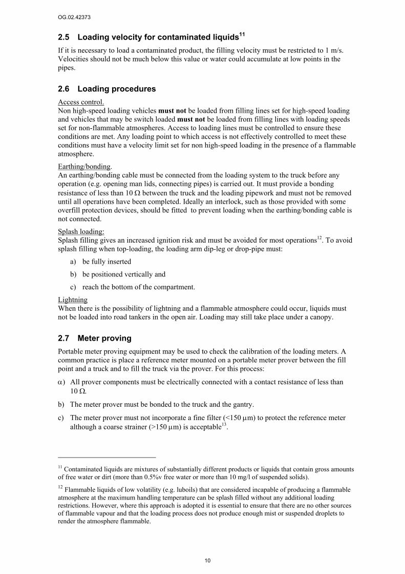
2.5 Loading velocity for contaminated liquids11 If it is necessary to load a contaminated product, the filling velocity must be restricted to 1 m/s. Velocities should not be much below this value or water could accumulate at low points in the pipes.
2.6 Loading procedures Access control. Non high-speed loading vehicles must not be loaded from filling lines set for high-speed loading and vehicles that may be switch loaded must not be loaded from filling lines with loading speeds set for non-flammable atmospheres. Access to loading lines must be controlled to ensure these conditions are met. Any loading point to which access is not effectively controlled to meet these conditions must have a velocity limit set for non high-speed loading in the presence of a flammable atmosphere.
Earthing/bonding. An earthing/bonding cable must be connected from the loading system to the truck before any operation (e.g. opening man lids, connecting pipes) is carried out. It must provide a bonding resistance of less than 10 Ω between the truck and the loading pipework and must not be removed until all operations have been completed. Ideally an interlock, such as those provided with some overfill protection devices, should be fitted to prevent loading when the earthing/bonding cable is not connected.
Splash loading: Splash filling gives an increased ignition risk and must be avoided for most operations12. To avoid splash filling when top-loading, the loading arm dip-leg or drop-pipe must:
a) be fully inserted
b) be positioned vertically and
c) reach the bottom of the compartment.
Lightning When there is the possibility of lightning and a flammable atmosphere could occur, liquids must not be loaded into road tankers in the open air. Loading may still take place under a canopy.
2.7 Meter proving Portable meter proving equipment may be used to check the calibration of the loading meters. A common practice is place a reference meter mounted on a portable meter prover between the fill point and a truck and to fill the truck via the prover. For this process:
α) All prover components must be electrically connected with a contact resistance of less than 10 Ω.
b) Τhe meter prover must be bonded to the truck and the gantry.
c) The meter prover must not incorporate a fine filter (<150 µm) to protect the reference meter although a coarse strainer (>150 µm) is acceptable13.
11 Contaminated liquids are mixtures of substantially different products or liquids that contain gross amounts of free water or dirt (more than 0.5%v free water or more than 10 mg/l of suspended solids). 12 Flammable liquids of low volatility (e.g. luboils) that are considered incapable of producing a flammable atmosphere at the maximum handling temperature can be splash filled without any additional loading restrictions. However, where this approach is adopted it is essential to ensure that there are no other sources of flammable vapour and that the loading process does not produce enough mist or suspended droplets to render the atmosphere flammable.

OG.02.42373
11
The facility manager should ensure that any meter proving equipment brought on to the site conforms with requirements a) and c) and has bonding connection point(s) suitable for the bonding connections required in b).
2.8 People Removal of clothing can generate incendive discharges so overalls or other clothing must not be removed in hazardous Zones.
The flapping of loose clothing can have the same effect as the removal of clothing so overalls should be a good fit and must be fastened whilst working in hazardous Zones.
Operators carrying out top loading in particular should not be permitted to keep items such as keys, tools or spectacles in unsecured top pockets from where they could drop into the compartment being loaded. Dropped items can act as charge collectors and initiate sparks. Consideration should be given to using overall designs that do not have top pockets.
The risk of people becoming charged is greater in dry climates and in particular in cold-dry climates. Where these occur, additional measures may be considered. The most important of these are the use of dissipative footwear and flooring. The use of dissipative gloves and clothing may also be considered. More details are given in Appendix H.
13 This is essential as there will not be an adequate residence time between the meter prover and the truck for the dissipation of any excess charge generated in the prover system. Major fires have occurred when this requirement has not been fulfilled.
OG.02.42373
12
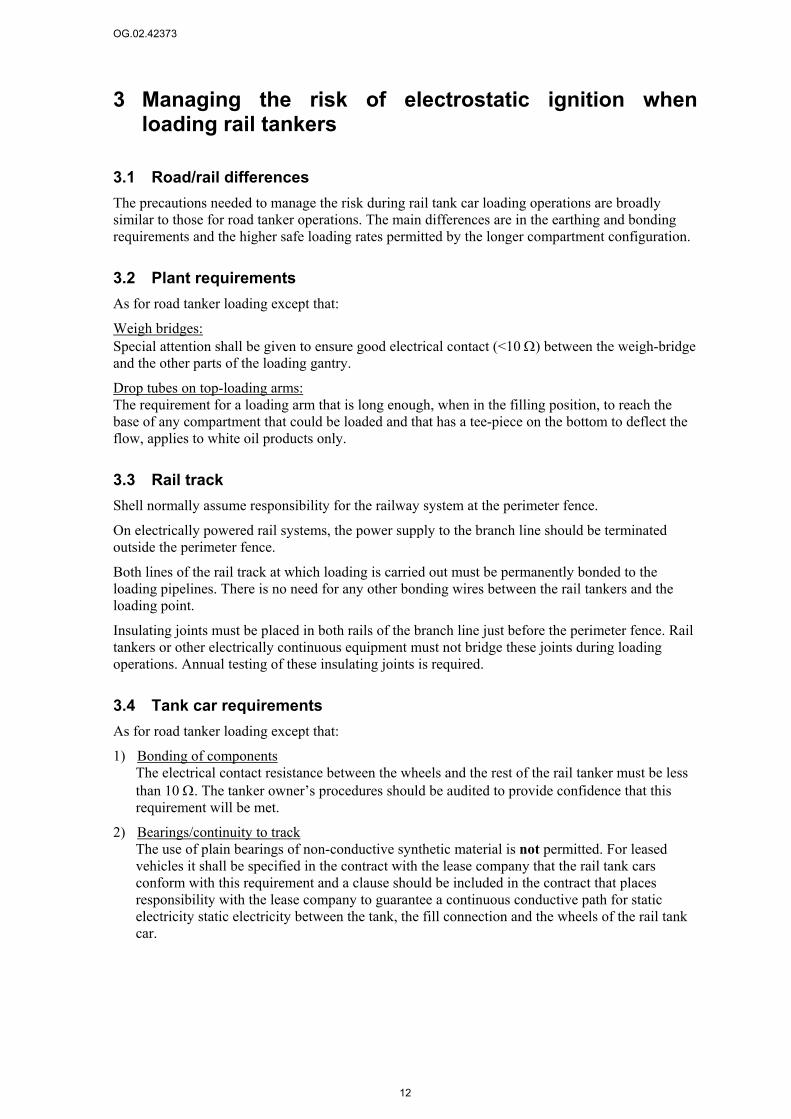
3 Managing the risk of electrostatic ignition when loading rail tankers
3.1 Road/rail differences The precautions needed to manage the risk during rail tank car loading operations are broadly similar to those for road tanker operations. The main differences are in the earthing and bonding requirements and the higher safe loading rates permitted by the longer compartment configuration.
3.2 Plant requirements As for road tanker loading except that:
Weigh bridges: Special attention shall be given to ensure good electrical contact (<10 Ω) between the weigh-bridge and the other parts of the loading gantry.
Drop tubes on top-loading arms: The requirement for a loading arm that is long enough, when in the filling position, to reach the base of any compartment that could be loaded and that has a tee-piece on the bottom to deflect the flow, applies to white oil products only.
3.3 Rail track Shell normally assume responsibility for the railway system at the perimeter fence.
On electrically powered rail systems, the power supply to the branch line should be terminated outside the perimeter fence.
Both lines of the rail track at which loading is carried out must be permanently bonded to the loading pipelines. There is no need for any other bonding wires between the rail tankers and the loading point.
Insulating joints must be placed in both rails of the branch line just before the perimeter fence. Rail tankers or other electrically continuous equipment must not bridge these joints during loading operations. Annual testing of these insulating joints is required.
3.4 Tank car requirements As for road tanker loading except that:
1) Bonding of components The electrical contact resistance between the wheels and the rest of the rail tanker must be less than 10 Ω. The tanker owner’s procedures should be audited to provide confidence that this requirement will be met.
2) Bearings/continuity to track The use of plain bearings of non-conductive synthetic material is not permitted. For leased vehicles it shall be specified in the contract with the lease company that the rail tank cars conform with this requirement and a clause should be included in the contract that places responsibility with the lease company to guarantee a continuous conductive path for static electricity static electricity between the tank, the fill connection and the wheels of the rail tank car.

OG.02.42373
13
3.5 Loading velocity for uncontaminated liquids14
3.5.1 Method for determining the loading velocity (flow chart) The velocity on each loading point must be set below a limit that is determined from the flammability of the vapour and the conductivity and sulphur content of the product.. The flow chart in Figure 2 shows how to determine the velocity limit for distillate-loading operations based on these criteria.
To use the flow chart it is necessary to:
e) Determine whether a flammable atmosphere could occur
f) Classify the product conductivity (≤50 pS/m, >50 pS/m or unknown)
g) Classify the product sulphur content (≤50 mg/kg, >50 mg/kg)
These steps are covered as for road tanker loading (Section 2.4.2).
FIG 2 Flowchart for determining the maximum safe loading velocity for rail tankers Notes:
(1) Flammable atmosphere. A flammable atmosphere should be considered possible if: a) switch loading may occur or b) there are common vapour lines and any vehicle compartment previously contained a volatile product or c) there is any possibility of a flammable atmosphere being introduced via VRU connections.
14 Contaminated liquids are mixtures of substantially different products or liquids that contain gross amounts of free water or dirt (more than 0.5%v free water or more than 10 mg/l of suspended solids). All other liquids may be considered as uncontaminated
Flammable atm possible in
compartments? (1)
v<7?
Conductivity?(2)
Reduce loading speed till v<7(3)
OK to load
S content?
vd<0.75,v<7?
vd<0.53,v<7?
Reduce loading speed till vd<0.75, v<7(3)
Reduce loading speed till vd<0.53, v<7(3)
OK to loadOK to load
c>50 pS/mc=<50 pS/m or unknown
S>=50 mg/kg
<50 mg/kg
Yes YesYesNo No No
Yes No
OG.02.42373
14
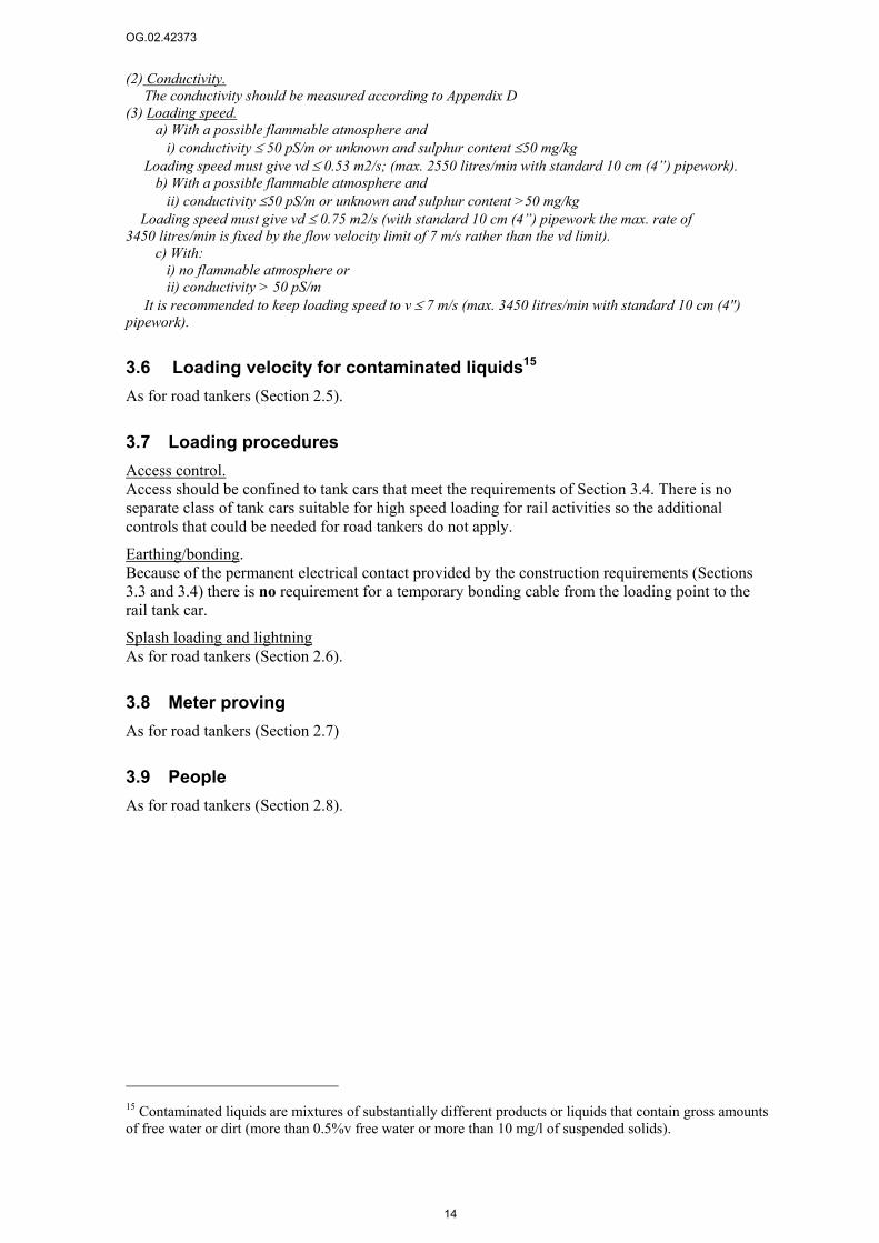
(2) Conductivity. The conductivity should be measured according to Appendix D (3) Loading speed. a) With a possible flammable atmosphere and i) conductivity ≤ 50 pS/m or unknown and sulphur content ≤50 mg/kg Loading speed must give vd ≤ 0.53 m2/s; (max. 2550 litres/min with standard 10 cm (4”) pipework). b) With a possible flammable atmosphere and ii) conductivity ≤50 pS/m or unknown and sulphur content >50 mg/kg Loading speed must give vd ≤ 0.75 m2/s (with standard 10 cm (4”) pipework the max. rate of 3450 litres/min is fixed by the flow velocity limit of 7 m/s rather than the vd limit). c) With: i) no flammable atmosphere or ii) conductivity > 50 pS/m It is recommended to keep loading speed to v ≤ 7 m/s (max. 3450 litres/min with standard 10 cm (4") pipework).
3.6 Loading velocity for contaminated liquids15 As for road tankers (Section 2.5).
3.7 Loading procedures Access control. Access should be confined to tank cars that meet the requirements of Section 3.4. There is no separate class of tank cars suitable for high speed loading for rail activities so the additional controls that could be needed for road tankers do not apply.
Earthing/bonding. Because of the permanent electrical contact provided by the construction requirements (Sections 3.3 and 3.4) there is no requirement for a temporary bonding cable from the loading point to the rail tank car.
Splash loading and lightning As for road tankers (Section 2.6).
3.8 Meter proving As for road tankers (Section 2.7)
3.9 People As for road tankers (Section 2.8).
15 Contaminated liquids are mixtures of substantially different products or liquids that contain gross amounts of free water or dirt (more than 0.5%v free water or more than 10 mg/l of suspended solids).

OG.02.42373
15
4 Managing the risk of electrostatic ignition when loading ships or barges
This section describes the safety precautions and other considerations when delivering or receiving, clean low-viscosity products, such as hydrocarbon fuels and solvents from ships and barges. It is a summary of Sections 4.4, 4.16, 6.5, and 6.10.3 of the Shell Safety Committee publication “Static Electricity - Technical and Safety Aspects” (June 1988).
The “International Safety Guide For Oil tankers & Terminals” (ISGOTT) (currently the 4th Edition, 1996) should be consulted to provide comprehensive guidance on all aspects of ship and marine terminal operations in which liquid products with low electrical conductivity, commonly referred to as ‘static accumulator cargoes’, are handled. This publication is the accepted international industry standard for both ship and marine terminal operations.
STASCO have also issued a “Marine Operations Manual” which has relevant references on this subject in Chapter 8. Further advice on shipping and marine matters can be obtained from STASCO, OTS/41.
4.1 Background In general, shipboard operations take place with cargo tank headspaces maintained in a flammable condition although some larger modern product carriers are equipped with inert gas systems, the proper use of which minimises risks associated with electrostatic charge generation.
Particular attention should be paid to determining the electrical conductivity of product being handled, so that the appropriate safety precautions can be followed. This is of greatest importance when the product conductivity is likely to be below the safety critical value of 50pS/m. As a guide; Crude Oils, Black Diesel Oils, Residual Fuel Oils, Asphalts, many Lubricating Oils and Heavy Gasoils will probably have an electrical conductivity greater than 50pS/m whilst other products e.g. Automotive Gasoils and Gasolines, Jet Fuel, Kerosenes, Naphthas, White Spirits, Base Oils and Re-refined Lubricating Oils, which have been subject to greater refinery processing can have either low (<50 pS/m) or high electrical conductivity depending on the nature of the processing received and what additives are present. Sections 4.2 and 4.3 describe the precautions for the different categories of product.
When loading product into ships and barges, the risk of electrostatic ignition is significantly less than when loading road tank cars and/or rail tankers, because the time taken to fill the cargo hold is much longer than the electrostatic charge relaxation time. Because of this, it is not considered necessary to set different precautions for standard low conductivity products (conductivity <50pS/m, S>50 mg/kg) and products with either very low electrical conductivity (< 10pS/m) or low sulphur content (<50 mg/kg).
Operating Units should review their current operating procedures for the transfer of product against the requirements that follow. In addition, marine terminal operators should be familiar with all aspects of marine operations as documented in ISGOTT.
It is important that strict procedures are followed when handling all static accumulator cargoes (conductivity <50 pS/nm). These procedures will generally address the need to restrict product flow rates and to implement specific precautions when using portable measuring and sampling equipment to gauge ship’s tanks.
4.2 Minimum precautions for all products The following minimum requirements shall be observed when static accumulator cargoes are being handled AND there is the possibility of a flammable atmosphere being formed during the operation.
OG.02.42373
16
• Confirmation from ship or barge that all internal tank pipework, portable measuring, sampling and tank cleaning equipment is in good order and securely earthed to the ships hull (ISGOTT).
• Prior to introducing metallic equipment into a non-inerted cargo tank, ensure that the recommended product relaxation time (30 minutes) for each tank is complied with to allow for settlement of free water and particles and the dissipation of any electrical potential. Exceptions are permitted if the vessel’s cargo tanks are provided with properly fitted sounding pipes.
• Confirm with vessel that the initial low product flow rates are agreed and recorded before transfer operations commence.
• Ensure that all relevant items on the ship/shore safety checklists, including, if relevant, the Crude Oil Washing and Inert Gas sections, are complied with (ISGOTT).
• Confirm with ship’s cargo officer that receiving tanks and lines are well drained or free of water.
• Confirm that ship’s cargo tanks have been cleaned to an agreed standard. It should be noted that third party vessels may not necessarily clean to the requirements laid down in Shell Charterers Instructions Appendix B. (Latest edition February 2002 - Refer STASCO OTO/3). However, ships that are required to clean between grades should do so to an agreed standard.
• Ensure that no loose objects, which could act as insulated conductors, are left in receiving tanks.
• Ensure procedures for line clearing with air/inert gas and connection/disconnection of hoses/arms are agreed (ISGOTT).
• The maximum safe initial filling rate should be established to ensure that the flow rate in any section of the ship and shore cargo pipeline system does not exceed a linear velocity of 1 m/s. (ISGOTT).
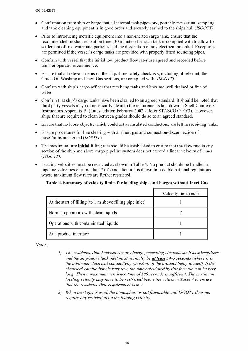
• Loading velocities must be restricted as shown in Table 4. No product should be handled at pipeline velocities of more than 7 m/s and attention is drawn to possible national regulations where maximum flow rates are further restricted.
Table 4. Summary of velocity limits for loading ships and barges without Inert Gas
Velocity limit (m/s)
At the start of filling (to 1 m above filling pipe inlet) 1
Normal operations with clean liquids 7
Operations with contaminated liquids 1
At a product interface 1
Notes :
1) The residence time between strong charge generating elements such as microfilters and the ship/shore tank inlet must normally be at least 54/σ seconds (where σ is the minimum electrical conductivity (in pS/m) of the product being loaded). If the electrical conductivity is very low, the time calculated by this formula can be very long. Then a maximum residence time of 100 seconds is sufficient. The maximum loading velocity may have to be restricted below the values in Table 4 to ensure that the residence time requirement is met.
2) When inert gas is used, the atmosphere is not flammable and ISGOTT does not require any restriction on the loading velocity.
OG.02.42373
17
4.3 Precautions for low conductivity (<50 pS/m) products Follow the Minimum precautions in Section 4.2 and manage the extra risk associated with low conductivity products by considering the adoption of a suitable combination of the following measures, depending on the exact circumstances at the loading/discharge facility and the ship/barge design.
Measures that reduce the risk of ignition by electrostatic discharge
Raise the electrical conductivity of the product to above 50pS/m using Static Dissipator Additive.
Measures that prevent formation of a flammable atmosphere
Use a vessel with an inert gas vapour space.
4.4 Other considerations
4.4.1 Ship/shore insulating, earthing and bonding Refer to ISGOTT.
4.4.2 Ship/shore bonding cables The use of ship/shore bonding cables is not recommended as this safety device is not considered effective and may even be dangerous. However, it is recognised that in some countries National or local regulations may still require the use of a ship/shore bonding cable and in such cases the precautions laid down in ISGOTT should be adhered too.
4.4.3 Insulating flanges/hose-strings Refer to ISGOTT.
In order to provide protection against arcing during connection and disconnection, the terminal operator should ensure that jetty hose connections and metal arms (including vapour return connections) are provided with properly fitted insulating flanges, as detailed in ISGOTT. The flange should be fitted so that the seaward side of the hose or arm is electrically continuous to the ship, and, on the inshore side of the flange, pipelines are earthed to the shore. Insulating flanges must be inspected and tested periodically to ensure that the insulation is clean and in good condition.
As an alternative to insulating flanges, a single length of electrically discontinuous hose should be used in each hose string.
Where ship to ship transfer operations are undertaken under the control of the terminal, the safety precautions outlined above in respect of ship / shore operations should be adhered too including pre-operational safety checks and the use of insulating flanges or single sections of electrically discontinuous hose in each string. If the safety precautions are not being followed on either vessel, the operations must not be started or, if in progress, must be stopped.
Ships using Single Buoy Moorings (SBMs) or Conventional Buoy Moorings (CBMs) should use electrically discontinuous hose strings.
4.4.4 Bunkering The hose requirements for bunkering should be the same as for product loading (i.e. the hoses should have an insulating flange or section). In particular where bunker fuel is supplied from a road vehicle, the vehicle should be bonded to the shore side equipment and the hose connections to the ship should be made via an insulating flange or a hose system with one electrically discontinuous section (see Section 4.4.3).
OG.02.42373
18
4.4.5 Inert gas systems Product tankers of over 20 ktonnes built after 1984 and some European barges are required to be fitted with inert gas systems. Group policy requires that any vessel that is equipped with an inert gas system uses it when loading, discharging or cleaning tanks.
Operations on inerted tankers should be subjected to joint verification by completion of the relevant safety checklist as specified in ISGOTT.
4.4.6 Portable equipment Ship cargo pipelines systems are designed to minimise the generation of electrostatic charges and filling points are located close to tank bottoms. Equipment that may generate electrostatic charges include portable tank cleaning machines and manual dipping, ullaging and sampling equipment. Such equipment must be bonded and securely earthed to the ship’s hull by means of a metallic connection between conductors before entry into any non-inerted cargo tank.

OG.02.42373
19
5 Other containers
5.1 Small containers (<50 l) and buckets It is often necessary to fill small containers or buckets with product. For these operations, the following rules should be applied:
• Containers with a capacity of 5 litres or less may be either conductive or insulating. Special earthing precautions are not essential for simple pouring operations although earthing of the container should be considered if there is a possibility of rapid flow (e.g. when taking samples from lines that may be at a high pressure).
• Containers with a capacity of more than 5 litres must be conductive (usually metal) and earthed unless there has been a detailed risk assessment of the activity taking into account expected levels of charge generation, dissipation and flammability.
• Where drum pumps are used they must be bonded both to the container being emptied and the container being filled.
• If a funnel is used it must be conductive or dissipative (generally metal) and bonded to the container being filled.
The ideal earthing/bonding connection consists of a bonding wire with a robust clip that can pierce rust or paint layers and that will not pull off or break during operations. The bonding wire must ensure good electrical contact (<10 Ω) between the container being filled and the source of the product (another container, a pump or pipework). Specific bonding connections must be used if there is any reason to suspect high charge generation (e.g. tapping off from a flowing system) or any doubt about the ability of the floor material to provide an earth path.
A less reliable approach, which is, nevertheless, often used for low charge-generating operations such as manual decanting, is to rely on the container standing on adequately conductive ground or other surface. Wood or concrete floors are generally sufficiently conductive but plastic or asphalt surfaces are not. Resistances to earth or between items can be verified with an insulation tester (megger) and should be less than 100 MΩ. A specific bonding link must be used if there is any doubt about the floor resistance.
5.2 Intermediate bulk containers (IBCs) Intermediate Bulk Containers (IBCs) are approximately cubic containers of around 1 m3 capacity that can be used for the transport and storage of liquid products. They may be all metal or they may have a plastic (usually HDPE) inner “bottle” with a supporting cubic metal frame (grid). The faces of the cube may be covered with metal sheet.
5.2.1 All metal IBCs These IBCs may be used for any hydrocarbon fuel subject to the following operational requirements.
a) The container must not previously have been used for more readily ignitable materials such as diethyl ether, ethylene oxide, cyclo propane or carbon disulphide.
b) The filling system pipes and fittings must be conductive and must be electrically connected together and to the filling system structure with a electrical contact resistance of less than 10 Ω.
c) Any flexible hoses used in the filling system or to connect to the IBC must be of conductive or dissipative construction. The end-to-end resistance and the mechanical integrity must be checked periodically.

OG.02.42373
20
a) Fill pipes, nozzles or funnels that enter the IBC must be conductive, long enough to reach the bottom of the IBC and bonded to the filling system. The pipework and connecting hoses may provide this electrical contact inherently. If not, a separate bonding connection must be provided.
d) A bonding cable must be provided to link the filling system to the IBC bonding point during filling. The cable must be firmly connected to the loading system and must have a robust clip that is strong enough to resist being pulled off the IBC accidentally during filling.
e) The IBC bonding cable must be connected to the IBC before removing the fill cap or inserting the filling lance and must not be removed until all filling has been completed. It must provide a electrical contact resistance of less than 10 Ω between the IBC and the filling system pipework.
f) Throughout the fill, the filling lance or funnel must be fully inserted so that it reaches the bottom of the container.
g) The filling rate must be less than 200 l/min. and the maximum flow speed must not exceed 7 m/s.
5.2.2 IBCs made of non-conductive material with a conductive enclosure These containers consist of a plastic “bottle” enclosed by metal sheeting or a metal grid. The acceptability of containers of this type for use with flammable hydrocarbons depends on whether the container meets the requirements of CENELEC R044-001 for use with Explosion Group IIa liquids.
5.2.2.1 IBCs with conductive enclosures that meet the CENELEC requirements for use with Explosion Group IIa liquids
IBCs meeting these requirements will be permanently labelled to show that they are suitable. If there is any doubt, confirmation must be sought from the container manufacturer. These containers may be used for all hydrocarbon fuels subject to the following operational requirements.
a) Take all the precautions required for metal IBCs plus the following:
b) The container must not be filled immediately after cleaning, manufacturing etc. when it may be hazardously charged.
c) Loading must not take place in a Zone 0 area.
d) The containers must not be filled more than once per day.
5.2.2.2 IBCs with conductive enclosures that do not meet the CENELEC requirements for use with Explosion Group IIa liquids
These must be treated as IBCs made of non-conductive material (see Section 5.2.3).
5.2.3 IBCs made of non-conductive material Non-conductive IBCs may be used in safe areas only, and may only be filled with non-flammable liquids or flammable liquids that are more than 15 C below their flash points. Filling operations for these liquids are subject to the following requirements:
a) All the precautions for metal IBCs must be followed.
b) The containers must not have previously contained more volatile flammable liquids.
c) Any conductive or dissipative components mounted on the IBC, must be earthed.
d) During filling operations, the liquid in the container must be in good contact with earth, for example, by an earthed metal fill pipe reaching to the bottom of the container.
e) Do not carry out operations, such as fast mixing, stirring or wiping of the surface, that may generate hazardous electrostatic charges

OG.02.42373
21
6 Information for 3rd parties or exchange partners
Operating Units should not undertake to advise 3rd parties on how to manage the risks at their own installations. However they are encouraged to share Shell's current knowledge (as contained in this Safety Advice) and how this knowledge is applied in Shell's own operations.


OG.02.42373
23
Appendix A: Site-specific rules example 1; small site
This Appendix gives an example of how the rules can be simplified if the specific operating circumstances at a particular site are taken into account. The recommendations below are fully compliant with the requirements in the main text but the site rules are expressed more simply because all mention of the factors that are inherently limited by the equipment at the site (e.g. the maximum available flow rate) has been omitted.
The potential for simplifying local rules is greatest at sites that have low loading speeds and no vapour recovery (like the case considered in this Appendix) and sites with dedicated vehicles.
A.1 Site Details • Small terminal, top-loading road tankers with gasoil, diesel and gasolines via jointed metal
loading arms. There is not enough confidence that splash loading can be prevented to permit the use of high-speed loading.
• Switch-loading is possible.
• Deliveries by road only.
• No low sulphur (<50 ppm) middle distillate.
• Maximum available pumping rate 1050 l/min (~4 m/s in a 3” line).
• No VRU.
• Meter proving done by loading a truck via a portable reference meter.
A.2 Plant requirements General earthing or bonding: All pipes in the loading system must be conductive.
All components of the liquid handling system (pipework, filters, metering or loading arm) must be electrically connected to the loading system structure. The electrical contact resistance must be less than 10 Ω for items that are connected metal to metal.
Swivel joints: Swivel joints may not give metal to metal connection. For these it must be verified that the electrical contact resistance is consistently less than 1 MΩ. Normally the resistance across a swivel joint is low enough (a few kΩ) but some greases can be highly insulating and electrical continuity across swivel joints needs to be checked. Checks should be done for several positions of each joint because the resistance can vary. If continuity over a swivel joint is inadequate, the resistance can be reduced by changing to a more conductive grease or by providing a bonding link across the joint.
Drop tubes on top-loading arms: Drop tubes on top-loading arms must be metal and must be long enough to reach the base of all compartments to be loaded. They should have a tee-piece on the bottom to deflect the flow along the base of the compartment.
A.3 Vehicle requirements Bonding of vehicle components: The electrical contact resistance between the chassis, the tank and the associated pipes and fittings on the truck must be less than 10 Ω. Pipework should generally be conductive but plastic vapour lines are acceptable.
Compartments clear of debris Conductive debris (cans, buckets or even smaller items such as tools) inside truck compartments

OG.02.42373
24
can promote electrostatic discharges. It is therefore essential to ensure, before loading, that all compartments are clear of such debris.
A.4 Assurance Programmes of routine monitoring, including pre-loading checks and technical audit on plant and trucks/truck owners must be used to ensure that the requirements in Sections A.2 and A.3 are met.
A.5 Loading velocity for uncontaminated liquids16 The maximum permissible flow rate is 1340 l/min17. The maximum available flow rate for any line on site (limited by the pump and piping characteristics) is only ~1050 l/min which is low enough for safe loading of all the available products in all types of vehicle irrespective of Flammability or Product Conductivity. Thus, flow rate issues need not be considered further and no specific controls are needed.
Flow rates must be reconsidered if the available flow rate in any line is increased above 1340 l/min.
A.6 Loading velocity for contaminated liquids18 If it is necessary to load a contaminated product, the filling velocity must be restricted to 1 m/s (~250 l/min). Velocities should not be much below this value or water could accumulate at low points in the pipes.
A.7 Loading procedures Earthing/bonding. An earthing/bonding cable must be connected from the loading system to the truck before any operation (e.g. opening man lids, inserting loading arms) is carried out. It must provide a electrical contact resistance of less than 10 Ω between the truck and the loading pipework and must not be removed until all operations have been completed. It is recommended that interlocks are provided to prevent loading when the earthing/bonding cable is not connected.
Splash loading: Splash filling gives an increased ignition risk and must be avoided for most operations19. To avoid splash filling when top loading, the loading arm (or dip-leg or drop-pipe) must:
a) be fully inserted
b) be positioned vertically and
c) reach the bottom of the compartment.
16 Contaminated liquids are mixtures of substantially different products or liquids that contain gross amounts of free water or dirt (more than 0.5%v free water or more than 10 mg/l of suspended solids). All other liquids can be regarded as uncontaminated. 17 A flammable atmosphere may exist in the compartments, the product conductivity may be less than 10 pS/m, the sulphur content of all middle distillates at the site exceeds 50 mg/kg and the vehicles are not suitable for high speed loading. For these conditions, the vd value must not exceed 0.38 m2/s (see Figure 1 of the main text). This corresponds to 1340 l/min with the 7.5 cm (3″) pipework installed at the site.. 18 Contaminated liquids are mixtures of substantially different products or liquids that contain gross amounts of free water or dirt (more than 0.5%v free water or more than 10 mg/l of suspended solids). 19 Flammable liquids of low volatility (e.g. luboils) that are considered incapable of producing a flammable atmosphere at the maximum handling temperature can be splash filled without any additional loading restrictions. However, where this approach is adopted it is essential to ensure that there are no other sources of flammable vapour and that the loading process does not produce enough mist or suspended droplets to render the atmosphere flammable.

OG.02.42373
25
Lightning When there is the possibility of lightning and a flammable atmosphere could occur, liquids must not be loaded into road tankers in the open air. Loading may still take place under a canopy.
A.8 Meter proving into a truck via a portable meter prover a) All prover components must be electrically connected with a resistance of less than 10 Ω.
b) Τhe prover must be bonded to the truck and the gantry.
c) The prover must not incorporate a fine filter (<150 µm) to protect the reference meter although a coarse strainer (>150 µm) is acceptable20.
The terminal manager must ensure that any meter proving equipment brought on to the site conforms with requirements a) and c) and has bonding connection point(s) suitable for the bonding connections required in b).
A.9 Small containers (<50 l) and buckets It is often necessary to fill small containers or buckets with product. For these operations, the following rules should be applied:
• Containers with a capacity of 5 litres or less may be either conductive or insulating and no special earthing precautions are needed.
• Containers with a capacity of more than 5 litres must be conductive (usually metal) and earthed via a bonding wire with a robust clip that can pierce rust or paint layers and that will not pull off or break during operations. The bonding wire must ensure good electrical contact (<10 Ω) between the container being filled and the source of the product (another container, a pump or pipework).
• Where drum pumps are used they must be bonded both to the container being emptied and the container being filled.
• If a funnel is used it must be conductive or dissipative (generally metal) and bonded to the container being filled.
A.10 People Removal of clothing can generate incendive discharges so overalls or other clothing must not be removed in hazardous Zones.
The flapping of loose clothing can have the same effect as the removal of clothing so overalls should be a good fit and must be fastened whilst working in hazardous Zones.
Operators carrying out top loading in particular must not be permitted to keep items such as keys, tools or spectacles in unsecured top pockets from where they could drop into the compartment being loaded. Dropped items can act as charge collectors and initiate sparks. Consideration should be given to using overall designs that do not have top pockets.
20 This is essential as there will not be an adequate residence time between the meter prover and the truck for the dissipation of any excess charge generated in the prover system. Major fires have occurred when this requirement has not been fulfilled.


OG.02.42373
27
Appendix B: Site-specific rules example 2; large site
This Appendix gives an example of how the rules can be simplified if the specific operating circumstances at a particular site are taken into account. The potential for simplifying the local rules is less in this example than the others because of high loading speeds and vapour recovery. However, despite the onerous operating conditions, the recommendations for a given loading rack can be expressed more simply than in the main text because choices have been made rather than leaving options open. The recommendations below are fully compliant with the requirements in the main text.
B.1 Site Details • A large, pipeline-fed, road-tanker loading terminal in a temperate climate.
• No rail or barge loading operations.
• Mainly bottom-loading but some legacy top-loading.
• Products handled are gasolines (several grades), gasoil, diesel and kerosenes (includes Jet-A1 but aviation fuel handling is beyond the scope of the present document).
• Risk assessments and procedures are in place to allow top-loading vehicles to be considered suitable for high-speed loading. The loading arms are long enough to comfortably span the length of all vehicles to be loaded with an adequate margin for parking inaccuracy.
• All vehicles taking low sulphur diesel are bottom loading and suitable for high-speed loading. Some vehicles bottom-loading standard middle distillates are not suitable for high-speed loading.
• Switch-loading occurs.
• Low sulphur (<50 ppm ) diesel is handled.
• The maximum available pumping rate exceeds 2400 l/min .
• All loading is via 4″ lines.
• Hoses are made to conductive standards.
• There is a VRU connected to gasoline bottom-loading only.
• Meter proving is done by loading a truck via a portable reference meter.
B.2 Common requirements for all loading points
B.2.1 Plant requirements General earthing or bonding: All pipes in the loading system must be conductive.
All components of the liquid handling system (pipework, filters, metering, loading arm or hose) must be electrically connected to the loading system structure with an electrical contact resistance of less than 10 Ω.
Swivel joints: Swivel joints may not give metal to metal connection. For these it must be verified that the electrical contact resistance is consistently less than 1 MΩ. Normally the resistance across a swivel joint is low enough (a few kΩ) but some greases can be highly insulating and electrical continuity across swivel joints needs to be checked. Checks should be done for several positions of each joint

OG.02.42373
28
because the resistance can vary. If continuity over a swivel joint is inadequate, the resistance can be reduced by changing to a more conductive grease or by providing a bonding link across the joint.
Hoses: The flexible hoses used for bottom loading must meet the required standards for fuel hoses including conductive resistance standards. They must have an end-to-end resistance of less than 10 Ω. The condition of hoses must be checked visually every 3 months and the end-to-end (i.e. coupling to coupling) resistance must be measured every 6 months. Both these checks must also be done if the hose may have been damaged (e.g. if it has been run over). Hoses must be discarded if there is a break or any obvious permanent distortion of the external helix or if the end-to-end resistance increases by more than 30% (care is needed to ensure good contact before concluding there has been a resistance increase).
B.2.2 Vehicle requirements Bonding of vehicle components: The electrical contact resistance between the chassis, the tank and the associated pipes and fittings on the truck must be less than 10 Ω. Pipework should generally be conductive but plastic vapour lines are acceptable.
Compartments clear of debris Conductive debris (cans, buckets or even smaller items such as tools) inside truck compartments can promote electrostatic discharges. It is therefore essential to ensure before loading that all compartments are clear of such debris.
B.2.3 Assurance Programmes of routine monitoring, including pre-loading checks and technical audit on plant and trucks must be used to ensure that the requirements in Sections B.2.1 and B.2.2 are met.
B.2.4 Loading velocity for contaminated liquids21 If it is necessary to load a contaminated product, the filling velocity must be restricted to 1 m/s (~350 l/min). Velocities should not be much below this value or water could accumulate at low points in the pipes. The loading velocities mentioned in Section B.3 are for uncontaminated product only
B.2.5 Loading procedures: bonding. A bonding cable must be connected from the loading system to the truck before any operation (e.g. opening man lids, connecting pipes) is carried out. It must provide a electrical contact resistance of less than 10 Ω between the truck and the loading pipework and must not be removed until all operations have been completed. It is recommended that interlocks are provided to prevent loading when the earthing cable is not connected.
B.2.6 Meter proving a) All prover components must be electrically connected with an electrical contact resistance of
less than 10 Ω.
b) Τhe prover must be bonded to the truck and the gantry.
c) The prover must not incorporate a fine filter (<150 µm) to protect the reference meter although a coarse strainer (>150 µm) is acceptable22.
21 Contaminated liquids are mixtures of substantially different products or liquids that contain gross amounts of free water or dirt (more than 0.5%v free water or more than 10 mg/l of suspended solids).

OG.02.42373
29
The terminal manager must ensure that any meter proving equipment brought on to the site conforms with requirements a) and c) and has bonding connection point(s) suitable for the bonding connections required in b).
B.2.7 Small containers (<50 l) and buckets It is often necessary to fill small containers or buckets with product. For these operations, the following rules should be applied:
• Containers with a capacity of 5 litres or less may be either conductive or insulating and no special earthing precautions are needed.
• Containers with a capacity of more than 5 litres must be conductive (usually metal) and earthed via a bonding wire with a robust clip that can pierce rust or paint layers and that will not pull off or break during operations. The bonding wire must ensure good electrical contact (<10 Ω) between the container being filled and the source of the product (another container, a pump or pipework).
• Where drum pumps are used they must be bonded both to the container being emptied and the container being filled.
• If a funnel is used it must be conductive or dissipative (generally metal) and bonded to the container being filled.
B.2.8 People Removal of clothing can generate incendive discharges so overalls or other clothing must not be removed in hazardous Zones.
The flapping of loose clothing can have the same effect as the removal of clothing so overalls should be a good fit and must be fastened whilst working in hazardous Zones.
Operators carrying out top-loading in particular must not be permitted to keep items such as keys, tools or spectacles in unsecured top pockets from where they could drop into the compartment being loaded. Dropped items can act as charge collectors and initiate sparks. Consideration should be given to using overall designs that do not have top pockets.
B.3 Additional specific requirements for particular loading points:
B.3.1 Gasoline loading rate The rate for all gasoline loading must be fixed according to vd≤0.5 m2/s23. This corresponds to a volumetric rate of ≤2400 l/min (5 m/s) in the 4" piping used at the site. The pumps are capable of delivering more than this rate to each fill point, particularly if only one is active, therefore flow control is needed for each fill point to ensure the maximum is not exceeded.
B.3.2 Low sulphur diesel: bottom loading
B.3.2.1 Relevant loading conditions
• The atmosphere could sometimes be flammable because of switch loading.
• The product conductivity is controlled to be >10 pS/m (see Section B.3.3.3).
22 This is essential as there will not be an adequate residence time between the meter prover and the truck for the dissipation of any excess charge generated in the prover system. Major fires have occurred when this requirement has not been fulfilled. 23 From Figure 1 with gasoline loading. The truck and conductivity factors are irrelevant for gasoline.

OG.02.42373
30
• Access to the low sulphur diesel loading points is restricted to approved high-speed loading vehicles.
B.3.3.2 Normal loading velocity
The loading rate for low sulphur diesel is fixed according to vd≤0.5 m2/s24. This corresponds to a volumetric rate of ≤2400 l/min in the 4" piping used at the site. The pumps are capable of delivering more than this to each fill point, particularly if only one line is active, therefore flow control is needed on each low sulphur diesel arm to ensure the maximum is not exceeded.
B.3.3.3 Conductivity assurance Low sulphur diesel shall be supplied to a specified target conductivity of 50 pS/m.
A conductivity check shall be carried on each batch of product out prior to accepting delivery. The supplier shall be warned if the conductivity falls below 50 pS/m and instructed to ensure an acceptable delivered conductivity with future batches. If the delivered conductivity is below 40 pS/m, the batch must be carefully monitored in tankage and re-doped if necessary to achieve the conductivity level in the following paragraph (30 pS/m).
Even if the delivered conductivity is acceptable, conductivity checks shall be carried out periodically in storage tanks at the site. Initially tests should be done on every batch but the testing frequency may be reduced to monthly with good experience. Re-doping with additional static dissipator additive shall be carried out if the conductivity in tankage is found to be below 30 pS/m. Re-doping procedures are given in Appendix G.
Conductivity verification checks shall be carried out on samples of loaded product. The frequency of checking and re-doping in tankage shall be increased if any conductivity below 10 pS/m is found.
B.3.3.4 Access control Access to the low-sulphur-diesel loading points shall be confined to approved vehicles suitable for high-speed loading. A key card or code system is recommended.
B.3.4 Other kerosene, diesel and gasoil: legacy top loading
B.3.4.1 Relevant loading conditions
• All top-loading vehicles are treated as high-speed loading vehicles. This requires the additional precautions sat out in B.3.4.3.
• The occurrence of flammable atmospheres must be allowed for because of switch loading and because, under hot summer conditions, the temperature will be within 15 C of the kerosene flash point.
• The product conductivity is not controlled
B.3.4.2 Normal loading velocity
The loading rate for these activities is fixed according to vd≤0.5 m2/s25. This corresponds to a volumetric rate of 2400 l/min (5 m/s) in the 4" piping used at the site. The pumps are capable of delivering more than this rate to each fill point, particularly if only one is active, therefore flow control is needed on each arm to ensure that the limit is not exceeded.
24 From Figure 1 with a flammable atmosphere, controlled conductivity >10 pS/m, middle-distillate low S product and a line used by high-speed-loading vehicles only. 25 From Figure 1 with a possible flammable atmosphere, possible low conductivity, non low S or non-middle distillate product and a high-speed-loading vehicle. Use vd≤0.38 m2/s if it is not certain that splash loading will be prevented by precautions such as those in B.3.4.3.
OG.02.42373
31
B.3.4.3 Additional precautions
• Drivers are made aware of the importance of avoiding splash loading and of not dropping any items into the compartment during loading.
• Drivers are made aware of the significance of misaligned (non-vertical) fill pipes for splash loading and hence are aware of the need for careful parking to ensure it is always possible to insert the drop tube vertically. Driver performance in this respect is subject to spot checks.
• Vehicles with a longer span between front and rear compartment manlids than a maximum permissible limit determined from the range of movement of the loading arms may not be loaded.
• Overalls without top pockets must be worn during loading to avoid the risk of dropping items into the compartments.
B.3.5 Other kerosene diesel and gasoil: bottom loading
B.3.5.1 Relevant loading conditions
• Loading is not restricted to dedicated or high-speed loading vehicles.
• The occurrence of flammable atmospheres must be allowed for because of switch loading and because, under hot summer conditions, the temperature will be within 15 C of the kerosene flash point.
• The product conductivity is not controlled
B.3.5.2 Normal loading velocity
The loading rate is fixed according to vd≤0.38 m2/s26. This corresponds to a volumetric rate of 1800 l/min (3.8 m/s) in the 4" piping used at the site. The pumps are capable of delivering more than this rate to each fill point, particularly if only one is active, therefore flow control is needed on each arm to ensure the maximum is not exceeded.
26 From Figure 1 with a possible flammable atmosphere, possible low conductivity, non low S or non-middle-distillate product and a non-high-speed-loading vehicle.

OG.02.42373
33
Appendix C: Site-specific rules example 3; dedicated vehicles
This Appendix gives an example of how the rules can be simplified if the specific operating circumstances at a particular site are taken into account. The potential for simplifying the local rules is greatest at sites with low loading speeds and/or dedicated vehicles and no vapour recovery. The recommendations below take full advantage of this. They are fully compliant with all the requirements in the main text but the site rules can be expressed more simply because it is possible to omit from the specific rules all mention of the factors that are inherently limited by the equipment at the site (e.g. the dedicated vehicles).
C.1 Site Details • Top and bottom loading tankers with gasoil, diesel and gasolines via 4” lines.
• Bottom loading uses conductive hose connections
• Dedicated vehicles only so no switch loading occurs.
• No VRU.
• Meter proving done by loading a truck via a portable reference meter.
C.2 Common requirements for all loading points
C.2.1 Plant requirements General earthing or bonding: All pipes in the loading system must be conductive.
All components of the liquid handling system (pipework, filters, metering, loading arm or hose) must be electrically connected to the loading system structure with a electrical contact resistance of less than 10 Ω.
Swivel joints Swivel joints may not give metal to metal connection. For these it must be verified that the electrical contact resistance is consistently less than 1 MΩ. Normally the resistance across a swivel joint is low enough (a few kΩ) but some greases can be highly insulating and electrical continuity across swivel joints needs to be checked. Checks should be done for several positions of each joint because the resistance can vary. If continuity over a swivel joint is inadequate, the resistance can be reduced by changing to a more conductive grease or by providing a bonding link across the joint.
Hoses: The flexible hoses used for bottom loading must meet the required standards for fuel hoses including conductive resistance standards. Hoses must have an end-to-end resistance of less than 10 Ω. The condition of hoses must be checked visually every 3 months and the end-to-end (i.e. coupling to coupling) resistance must be measured every 6 months. Both these checks must also be done if the hose may have been damaged (e.g. if it has been run over). Hoses must be discarded if there is a break or any obvious permanent distortion of the external helix or if the end-to-end resistance increases by more than 30% (care is needed to ensure good contact before concluding there has been a resistance increase).
C.2.2 Vehicle requirements Bonding of vehicle components: The electrical contact resistance between the chassis, the tank and the associated pipes and fittings

OG.02.42373
34
on the truck must be less than 10 Ω. Pipework should generally be conductive but plastic vapour lines are acceptable.
Compartments clear of debris Conductive debris (cans, buckets or even smaller items such as tools) inside truck compartments can promote electrostatic discharges. It is therefore essential to ensure before loading that all compartments are clear of such debris.
C.2.3 Assurance Programmes of routine monitoring, including pre-loading checks and technical audit on plant and trucks must be used to ensure that the requirements in Sections C.2.1 and C.2.2 are met.
C.2.4 Loading procedures: bonding. A bonding cable must be connected from the loading system to the truck before any operation (e.g. opening man lids, connecting pipes) is carried out. It must provide an electrical contact resistance of less than 10 Ω between the truck and the loading pipework and must not be removed until all operations have been completed.
C.2.5 Meter proving d) All prover components must be electrically connected with a resistance of less than 10 Ω.
e) Τhe prover must be bonded to the truck and the gantry.
f) The prover must not incorporate a fine filter (<150 µm) to protect the reference meter although a coarse strainer (>150 µm) is acceptable27.
The terminal manager must ensure that any meter proving equipment brought on to the site conforms with requirements a) and c) and has bonding connection point(s) suitable for the bonding connections required in b).
C.2.6 Small containers (<50 l) and buckets It is often necessary to fill small containers or buckets with product. For these operations, the following rules should be applied:
• Containers with a capacity of 5 litres or less may be either conductive or insulating and no special earthing precautions are needed.
• Containers with a capacity of more than 5 litres must be conductive (usually metal) and earthed via a bonding wire with a robust clip that can pierce rust or paint layers and that will not pull off or break during operations. The bonding wire must ensure good electrical contact (<10 Ω) between the container being filled and the source of the product (another container, a pump or pipework).
• Where drum pumps are used they must be bonded both to the container being emptied and the container being filled.
• If a funnel is used it must be conductive or dissipative (generally metal) and bonded to the container being filled.
27 This is essential as there will not be an adequate residence time between the meter prover and the truck for the dissipation of any excess charge generated in the prover system. Major fires have occurred when this requirement has not been fulfilled.
OG.02.42373
35
C.2.7 People Removal of clothing can generate incendive discharges so overalls or other clothing must not be removed in hazardous Zones.
The flapping of loose clothing can have the same effect as the removal of clothing so overalls should be a good fit and must be fastened whilst working in hazardous Zones.
Operators carrying out top loading in particular must not be permitted to keep items such as keys, tools or spectacles in unsecured top pockets from where they could drop into the compartment being loaded. Dropped items can act as charge collectors and initiate sparks. Consideration should be given to using overall designs that do not have top pockets.
C.3 Loading rates
C.3.1 Relevant loading conditions
C.3.1.1 Gasoline
• The atmosphere could be flammable (although it will usually be over-rich).
• The products could have low conductivity.
• Some, or all, of the vehicles that bottom-load gasoline at this site are unsuitable for high-speed loading. There are no access restrictions to confine these vehicles to specified low speed lines.
• Top-loading vehicles are not suitable for high-speed loading because additional procedures are not in place.
C.3.1.2 Diesel and gas oil (top and bottom loading)
• The atmosphere above these fuels will not be flammable because there is no switch loading, no VRU connection and the maximum ambient temperature is more than 15 C below the lowest flash point.
• The product conductivity is not controlled and could be low.
C.3.2 Normal loading velocity The rate for loading all products at this site is fixed according to vd≤0.5 m2/s28. This corresponds to a volumetric rate of ≤2400 l/min (5 m/s) in the 4" piping used at the site. Flow control is needed at each fill point to ensure this maximum is not exceeded.
C.3.3 Loading velocity for contaminated liquids29 If it is necessary to load a contaminated product, the filling velocity must be restricted to 1 m/s (~350 l/min). Velocities should not be much below this value or water could accumulate at low points in the pipes.
28 From Figure 1 with either gasoline loading or loading without a flammable atmosphere. The truck and conductivity factors are irrelevant for these cases. 29 Contaminated liquids are mixtures of substantially different products or liquids that contain gross amounts of free water or dirt (more than 0.5%v free water or more than 10 mg/l of suspended solids).

OG.02.42373
37
Appendix D: Procedure to measure the conductivity of gasoils
The recommended types of fuel conductivity meter and their use are covered in Appendix 02.03.06 of the Shell Airport Operations Manual. Fuel conductivity is normally measured by means of a Emcee or Maihak meter in accordance with ASTM method D2624 (IP 274). This Appendix gives a modified version of this method making it also applicable for gasoils.
Whenever possible, conductivity should be measured at the tank either by checking a sample at tank side using an Emcee meter in a sample jar or by lowering the immersion cell of the Maihak meter directly into the bulk fuel contents of a storage tank. In the case of large tanks, measurements should be made or samples drawn at upper, middle and lower levels because of possible stratification.
D.1 In–situ measurements Maihak cells (see E.3) are the most suited to in-situ measurements. Specific operating instructions for these are given in E.3.
To prevent a static electrical discharge between the fuel and a cell lowered into the tank, it is recommended that a minimum of 5, but preferably 30, minutes should elapse after a tank has been replenished to allow for the dissipation of any static charge. The procedure may then continue as follows using a cell of confirmed cleanliness as outlined in Section E.3.2:
1) Bond the earth terminal of the meter to the tank or vessel.
2) Lower the immersion cell to the desired level. Where 3 levels are called for these should be:
a) Top: just under the surface of the fuel (care must be taken to avoid partial immersion of the cell)
b) Middle: the middle depth of the tank contents.
c) Lower: the middle depth of the lower third of the tank contents (care must be taken to avoid contact with the tank bottom that may be dirty or wet)
3) Raise and lower the immersion cell in the fuel as a ‘flushing’ action to remove previous residues from its surfaces.
4) Make the measurement according to the operating instructions for the cell concerned. Instructions for the most common in-situ measuring cell (the Maihak) are given in E.3.
D.2 Measurements on samples Because it has a much smaller probe than the Maihak, the Emcee meter is the most suitable for testing samples drawn out from a storage tank or vehicle. The Maihak can still be used for this purpose if in-situ measurements are impracticable but requires larger samples. The Maihak meter also allows the fuel temperature to be measured. The Emcee meter does not offer this option which means that a separate thermometer is required when fuel temperature has to be recorded (as recommended in Section 2.4.2.2.
The following precautions are generally applicable for testing samples in small containers with either Emcee or Maihak meters:
1) Samples should be as large as practicable and never less than one litre.
2) All sample containers must be thoroughly cleaned and dried. Prior to taking the samples, all containers (including any caps) must be rinsed at least three times with the fuel to be checked.

OG.02.42373
38
3) Either draw a sample from a low point drain or obtain a top, middle or bottom dip sample of at least 1 litre. Wait for a period of at least 2 minutes to allow any static electricity to dissipate before using the meter.
4) If possible, the conductivity should be measured directly in the sample container. Otherwise the sample should be transferred to a suitable measuring vessel that must first be thoroughly cleaned and rinsed 3 times with the sample.
5) If possible, testing should be carried out within a few minutes of sampling otherwise the temperature could change significantly.
6) If storage cannot be avoided before testing, the product temperature should be measured immediately and subsequent measurements done later in temperature-controlled conditions that replicate the product temperature.
7) Care is necessary in the selection of storage containers to avoid significant errors in the results. Polyethylene containers are unsatisfactory and must not be used. If samples are to be kept for more than 24 hours they should be stored in epikote-lined cans. Even with ideal storage, samples kept for more than three weeks may suffer significant changes in conductivity.
8) Conductivity can change significantly if fuel is exposed to daylight or fluorescent lights. Therefore samples should be stored in the dark.
D.3 In line measurements Electrical conductivity can also be measured with an in-line conductivity monitor, such as the Staticon Model 1150. This instrument give a continuous recording of fuel conductivity and also gives an output signal which can be used to activate a high/low level conductivity alarm or to provide feed-back control of an additive injection device. The use of such a system on a bridger loading rack would avoid the need to check the conductivity before release of depot tanks supplied by bridgers doped (by pouring in Stadis 450-mix) during loading.
OG.02.42373
39
Appendix E: Conductivity meters: which types and how to use
E.1. Introduction The electrical conductivity of a liquid indicates its ability to dissipate charge. It is measured with a conductivity meter. The measurement units are picoSiemens/metre (pS/m) which are also known as ‘Conductivity Units’ (CU).
E.2. Emcee conductivity meter The Emcee Conductivity Meter is a light, hand-held, battery operated instrument for measuring the conductivity of small jet fuel samples. It is more suitable for checking fuel samples in cans or other sample containers than for in-situ measurements in storage tanks30. It is easy to calibrate and zero check.
Models 1151A (with analogue display) and 1152 (with digital display) are both approved by Shell Aviation Ltd, London and their use is detailed below. Model 1152 is certified intrinsically safe and is therefore recommended.
E.2.1 Calibration Before each series of measurements, the calibration of the meter must be checked as follows, and adjusted as necessary. These checks are all performed with the probe in air not fuel.
1) Zero checking
a) Attach the probe to the bottom connector on the conductivity meter.
b) Hold the meter with the probe vertical and depress the MEASURE switch M. Within 3 seconds the 1151A pointer should register zero, with no greater deflection than ± 1 division and the 1152 model should indicate a reading of 000 ± 001.
c) If the meter reading is outside these limits, remove the probe and recheck the zero for the meter alone by pressing M again.
i) If the zero reading is outside the limits without the probe, insert a small screwdriver into the hole marked ZERO and adjust whilst the M switch is depressed.
ii) If the zero reading is inside the limits without a probe but outside the limits when a probe is attached, clean the probe by rinsing with isopropyl alcohol or white spirit, allow it to dry and retest. If the meter still does not read 000, ± 001, or zero, ± 1 division, with the probe attached, insert a small screwdriver into the hole marked ZERO and adjust whilst the M switch is depressed.
2) Calibration
a) For model 1151A, set CU RANGE to CAL on the latest version, or to x1 on earlier versions. Depress both the MEASURE and the CALIBRATE switches together and allow the pointer to stabilise. The meter reading should be equal to the cell constant value stamped on the probe (± 1 division). If re-calibration is necessary, insert a small screwdriver in the side panel hole marked CAL, and adjust the meter reading to the value stamped on the probe, whilst keeping the MEASURE and CALIBRATE switches depressed.
b) For other models, hold the meter with the probe vertical and depress the CALIBRATE switch C. The meter reading should be 10 times the cell constant value stamped on the
30 An extension kit is available for use in storage tanks but this is not recommended.
OG.02.42373
40
probe ± 005, e.g. if the cell constant is 40, the meter reading should be in the range 395 to 405. If the meter reading is outside these limits, insert a small screwdriver into the hole marked CALIBRATE, and adjust the meter to 10 times the cell constant, (± 002), whilst keeping the switch C depressed.
E.2.2 Procedure for measuring conductivity of samples The conductivity of bulk stocks of middle distillate fuel may be determined as follows using the Emcee meter with the probe directly attached:
1) Use a sample taken as in Section D.2.
2) Insert the probe vertically into the fuel sample until the fuel level is aligned with the large holes near the top of the probe.
3) For model 1151A, set CU RANGE switch to x10, depress the MEASURE switch, allow the reading to stabilise and proceed as follows:
a) If the meter reading is between 5 and 50, multiply the reading by 10 and record the result.
b) If the meter reading is between 0 and 5, set CU RANGE switch to x1, depress the MEASURE switch, allow the reading to stabilise and record the result.
c) If the meter reading is greater than full scale on the x10 range, raise the probe until the fuel is aligned with the small holes, (half probe length), depress the MEASURE switch and allow the reading to stabilise, Multiply the meter reading by 20 and record the result.
4) For digital model 1152, depress the MEASURE switch M and record the reading after a stabilisation interval of approximately 3 seconds.
5) Measure the temperature of the bulk fuel or that of the sample at the time of the conductivity test.
E.2.3 Re-calibration and servicing Precise data can only be obtained from accurately calibrated meters in good working condition. It is, therefore, essential that instruments are checked prior to taking any readings, and are serviced and re-calibrated annually.
E.2.4 Storage of meters Experience has shown that these meters perform more reliably and with less need for frequent adjustment when the conditions of storage are similar to those that prevail in use. Extreme changes in temperature and humidity, e.g. going from a warm office to a cold storage tank can form condensation and change the calibration as the components adjust to ambient conditions. It is therefore recommended that Emcee meters are stored in conditions that are reasonably close to those that will be experienced in use.
It is recommended that meters are cleaned and dried after use and that their protective carrying case is not saturated in fuel. Malfunction can occur over time due to fuel vapour entering the meter and accumulating as a condensate or film on circuitry and connections.
E.3. Maihak Conductivity Meter, (Type MLA) The Maihak conductivity meter consists of an immersion cell, approximately 13m (40 ft) of cable wound on a reel and an indicating unit complete with scale, battery, and push-button controls. Maihak meters are particularly suitable for the in-situ monitoring of conductivity within storage tanks. They can be used for measuring the conductivity of drawn samples but they need much larger sample volumes than the Emcee meters.
Four model series with different characteristics are in use. The corresponding instrument numbers are:

OG.02.42373
41
Series Instrument Number 1 64001 to 64068, 64070 2 64069, 64071 to 64171 3 Prefix 2- 4 Prefix 3-
Series 2 and 3 instruments subsequently modified with parts supplied by the manufacturer bear the suffix ‘M’ after the instrument number.
E.3.1 Meter calibration The calibration of all Maihak meters should be completed as follows:
1) Ensure that the immersion cell is clean and dry.
2) Place it in the cell housing, ensuring that contact is made with the calibration resistor at the bottom.
3) Press the ‘READ’ button. Series 2m, 3, and 4 meters should read 465 pS/m, (± 10 pS/m) and Series 1 and unmodified Series 2 meters should give a reading of 500 pS/m (full scale).
4) For confirmation, press the ‘2x’ button and then the ‘READ’ button. Series 2m, 3, and 4 meters should now read 232 pS/m ( ± 10 pS/m) and Series 1 and unmodified Series 2 meters should now read 250 pS/m (± 10 pS/m).
5) Check the live zero reading by lifting the measuring cell slightly in its housing to break the contact with the calibration resistor, and press the ‘READ’ button. Repeat the process while pressing the ‘2x’ button.
6) For Series 3 and 4 instruments, a reading of zero should be obtained.
7) For Series 1 and 2 instruments, a positive reading of approximately 10 pS/m to 30 pS/m may be obtained. This must be recorded and subtracted from the indicated conductivity to obtain the final result.
E.3.2 Cleaning the cells Periodically, and particularly after use with a high conductivity liquid, the cell should be checked with a sample of product known to have a low conductivity to verify that low readings are attainable and that the readings are not influenced by contamination. If the cell does not read the expected low conductivity it must be cleaned and retested until it performs properly.
E.3.3 Procedure for measuring conductivity in-situ 1) With the cell in situ as a result of following the procedures in Section D.2, hold the
suspended cable steady, press the ‘READ’ button, and record the highest reading after the needle has recovered from the initial ‘over-swing’ caused by inertia. The initial over-swing should not exceed 20 pS/m, and should last no longer than one second.
2) If the reading is off-scale in the 500 pS/m range press the ‘2x’ button and then the ‘READ’ button. The resultant scale reading, after the initial over-swing, must then be multiplied by 2 to obtain the correct conductivity reading. If it is still off-scale record >1000 pS/m.
3) If Series 1 and 2 instruments are used, any offset readings found during the zero checks must be subtracted from the indicated reading to obtain the final result.
4) The temperature of the fuel at the relevant level for each conductivity reading should also be measured and recorded.

OG.02.42373
42
E.3.4 Re-calibration and servicing Precise data can only be obtained from accurately calibrated meters in good working condition. It is, therefore, essential that instruments are checked prior to taking any readings, and are serviced and re-calibrated annually.
E.3.4 Storage of meters Where possible, the Maihak meter should be stored at a temperature higher than the ambient at the time of taking measurements to avoid condensation on the immersion cell. The cell must be cleaned at intervals, especially if it has been in contact with dirt and/or water, by rinsing with a cleaning solvent and drying in a stream of air. Gross contamination may be removed after unscrewing the centring block.

OG.02.42373
43
Appendix F: Recording and analysing conductivity monitoring data
F.1 Record sheet for monitoring storage tanks
Date Time Tank number
Product temperature
Conductivity Remarks Name of operator
F.2 Control charts The use of Shewhart Control Charts (see SMS 1006-91) provides a systematic way of tracking measurement data and raising warnings if it varies from the norm or approaches specification limits. It is recommended that this approach be considered for the treatment of conductivity monitoring data.


OG.02.42373
45
Appendix G: Procedures for adding static dissipator additive to gasoils
G.1 General
G.1.1 Static Dissipator Additive (SDA): grade to be used Two SDA grades are available, Stadis 450 and Stadis 425. Stadis 450 is the only grade approved for use in Jet Fuels. Stadis 425 is an older version and is no longer aviation-approved. For harmonisation and to prevent misuse, refineries normally use only Stadis 450. At terminals and depots where no Jet Fuel is stored or if misuse can be eliminated by very clear labelling, Stadis 425 may be a useful option as it is about 30% cheaper. The supplier’s (Octel) list price for Stadis 450 is about 20 USD/kg in small 16 kg drums.
G.1.2 Preparation of stock solution Because of the very small quantity of Stadis required in the finished product, it is normally more convenient to make up and use a Stock Solution, i.e. a pre-diluted Stadis solution (often referred to as Stadis 450-mix). Kerosene or toluene are the preferred diluents because gasoil may cause problems in winter. The effect of kerosene on flash point and other properties is minor with common Stock Solution strengths (typically 10%v Stadis) because of the small amounts involved.
The additive amounts specified in the flowcharts of Section G.2, refer to undiluted Stadis 450 or 425. If a Stock Solution is used, the amount of Stock Solution to be added is increased in proportion to the dilution factor of the Stock Solution. Thus for example if the Stock Solution contains 10% additive, 10 mg/l of Stock Solution is required when 1 mg/l of additive is specified.31
G.2 Process for conductivity checking and additivation Flow chart G.1 below gives the steps required to check product conductivity on receipt at a terminal or depot and if necessary adjust additivation. Flow chart G.2 gives the steps required to check and adjust the conductivity of product already in depot tankage.
All dose rates mentioned in the flowcharts refer to undiluted Stadis 450 or 425. If a Stock Solution is used, the corresponding doses of Stock Solution need to be determined from the dilution as noted in Section G.1.2.
31 The specified additivation amounts are guidelines only so rigorous distinctions between mass and volume percents are not important here.

OG.02.42373
46
FIG G.1 Flowchart of procedure for checking and, if necessary, adjusting product conductivity on receipt at a depot
Notes for Flowchart G.1 10: If loading velocities are low enough (see Section 2.4), if product data can be relied upon or if the conductivity is to be
checked and adjusted in tankage there may be no need to check and adjust the conductivity on receipt.
50c required on receipt must be >80 pS/m
40c required on receipt must be >40 pS/m
80Add 1 mg/l
90Add 2 mg/l
100Add 3 mg/l
110In-line doping possible?
120Use in-line doping
140Dope into receiving tank before starting receipt of product
150Measure conductivity at 3 levels after receiving product
10Is conductivity (c) to be
checked/adjusted on receipt?
70What c increase is needed?
160c now above limit at all
tank levels?
<20 pS/m 20< Increase <50 pS/m >50 pS/m
Yes
No
Add data to conductivity recordsYes
60Conductivity above target?
Record data No further action neededYes
Record data and note failure to meet requirements
20Take sample(s) and measure electrical conductivity (c) or measure conductivity in situ
No action neededNo
30what is the min. c for
loading?10 pS/m 50 pS/m
Yes
Proceed
Start
No
130Measure conductivity in receiving tank before doping
170Adjust dosage as in Flowchart G.2
No
OG.02.42373
47
20: Take samples and measure the conductivity or measure the electrical conductivity in situ (see Appendices D and E); “Procedure to measure the conductivity of gasoils” and record the reading.
30: Decide what the minimum conductivity at the point of loading should be. The value adopted must be the highest value associated with any of the loading points.
40: If the conductivity at the point of loading is required to be > 10 pS/m then the conductivity on receipt must be > 40 pS/m 50: If the conductivity at the point of loading is required to be > 50 pS/m then the conductivity on receipt must be > 80 pS/m. 60-100: Depending on the increase required between the reading and the required level the following additive dosing
applies: Increase < 20 pS/m : 1 mg/l or ~ 1 litre per 1000 m3 Increase 20 pS/m to 50 pS/m : 2 mg/l or ~ 2 litres per 1000 m3 Increase > 50 pS/m : 3 mg/l or ~ 3 litres per 1000 m3
110-120: If design permits and costs can be justified, it is preferred to dope the additive via doping equipment into the product line using a pre-diluted stock solution (see G.1.2). The slower the doping rate (stretched throughout the product receipt time) the better the mixing. The use of this approach along with the recommended dose rate will guarantee sufficient high conductivity at the gantry. Conductivity checks in tankage are needed to guard against failure of the injection equipment.
130-150: If in line doping is not feasible the additive must be added to the receiving tank before the receipt of product commences. To enable optimum mixing, the use of a diluted stock solution is recommended (see G.1.2). Even when using a diluted stock solution, additive will not uniformly distribute and, whenever possible, agitation is recommended to ensure a homogeneous blend. After doping an adequate settling time (preferably several hours) should be allowed to ensure good mixing and uniform dispersal of the additive before checking the conductivity.
130, 150: Before and after doping, the conductivity and temperature of the batch should be measured and recorded. These data will be useful to build experience for feed back to the procedure owner or to suppliers as the recommended treat rates may need adjustment.
170: These further adjustments use conductivity measurements made in tankage. The conductivity margins may therefore be reduced from 30 pS/m to 20 pS/m for this step in accordance with Section 2.4. and Flowchart G.2.

OG.02.42373
48
FIG G.2: Flowchart of procedure for checking and, if necessary, adjusting the conductivity of product in depot tankage Notes for Flowchart G.2 10: If loading velocities are low enough (see Section 2.4 or if the conductivity is adequate on receipt there may be no need
to check and adjust the conductivity. 20: Take samples and measure the conductivity or measure the electrical conductivity in situ (See Appendices D and E);
“Procedure to measure the conductivity of gasoils” and record the reading.
50c required in tankage must be >70 pS/m
40c required in tankage must be >30 pS/m
80Add 1 mg/l
90Add 2 mg/l
100Add 3 mg/l
110Dope into tank
120Measure conductivity at 3 levels after doping
10Is conductivity (c) to be checked
and adjusted in tanks?
70What c increase is needed?
130c now above limit at all
tank levels?
<20 pS/m 20< Increase <50 pS/m >50 pS/m
60Conductivity above target?
Record data proceed
20Take sample(s) and measure electrical conductivity (c) or measure conductivity in situ
No action neededNo
30what is the min. c?
10 pS/m 50 pS/m
Yes
Start
No
No
Yes
Yes

OG.02.42373
49
30: Decide what the minimum conductivity at the point of loading should be. The value adopted must be the highest value associated with any of the loading points.
40: If the conductivity at the point of loading is required to be > 10 pS/m then the conductivity on receipt must be > 30 pS/m 50: If the conductivity at the point of loading is required to be > 50 pS/m then the conductivity on receipt must be > 70 pS/m. 60-100: Depending on the increase required between the reading and the required level the following additive dosing
applies: Increase < 20 pS/m : 1 mg/l or ~ 1 litre per 1000 m3 Increase 20 to 50 pS/m : 2 mg/l or ~ 2 litres per 1000 m3 Increase > 50 pS/m : 3 mg/l or ~ 3 litres per 1000 m3
110: To enable optimum mixing, the use of a diluted stock solution is recommended (see G.1.2). Even when using a diluted stock solution, additive will not uniformly distribute and, whenever possible, agitation is recommended to ensure a homogeneous blend.
120: After doping an adequate settling time (preferably several hours) should be allowed to ensure good mixing and uniform dispersal of the additive then the conductivity and temperature of the batch should be measured and recorded at 3 tank levels. These data will be useful to build experience for feedback to the procedure owner or to suppliers as the recommended treat rates may need adjustment.
130: Re-dope if the conductivity is still not right.

OG.02.42373
51
Appendix H: Risk factors
H.1 General The risk of explosion and/or fire occurs when there exists together a flammable fuel vapour in the right concentration range, air (or oxygen) and a source of ignition. The recommendations given in this Safety Advice are based on the principle that the risks can be managed by removing any of the three elements: the ignitable fuel vapour, the source of ignition or the air (oxygen).
H.2 Liquid properties
H.2.1 Conductivity Typically the risk of encountering an ignition source arising from static electricity is highest for conductivities around 1 pS/m. It remains important up to about 10 pS/m in the absence of strong charge generating mechanisms and up to about 50 pS/m in the presence of strong charge generating mechanisms (e.g. microfilters). Static electricity risks are very small in normal loading operations when the liquid conductivity exceeds 50 pS/m although they can occur in unusual circumstances that are normally avoided (e.g. if plastic pipes are used).
The conductivity checks recommended at the loading facility (see Section 2.4) for products that have a required minimum conductivity are an important supplement to conductivity specifications as they provide a safeguard against unexpectedly high additive depletion during shipment. Also, where tanker shipments are received from non-Shell sources, particularly on a random basis, the conductivity checks provide a safeguard against incorrect or inadequate doping by the supplying refinery. If re-doping is regularly needed, it may be possible to arrange for the supply source to dope initially to a higher conductivity level.
H.2.2 Sulphur content In the late 1990s there was a series of electrostatic ignition incidents when switch loading low sulphur AGO into road and rail tankers. In the light of these, Shell Service Company advisers reviewed the safety advice on loading operations. They concluded that very low sulphur (< 50 ppm S) automotive gasoils presented a significantly higher risk than other products. It is thought that the same risks would occur with similar non-automotive products if they were made to similar low sulphur specifications. A similar conclusion was drawn by an Institute of Petroleum study. Initially it was thought that the extra risk was associated with low conductivity but later work indicates that that increased charge generation is likely to be more significant. There is no evidence of increased risk with other low sulphur products such as pure chemicals, solvents or gasolines so the scope of extra precautions for low sulphur products is confined to middle distillates.
To deal with the increased risk that was identified, middle distillate products (IGO, AGO) are now classified on the basis of sulphur content. Products with >50 ppm S are considered to be of standard risk and those with <50 ppm S are considered to be of increased risk. In some operations, (e.g. loading high conductivity products) there have traditionally been large safety margins and it has not been necessary to change operating procedures to control the extra risk associated with low sulphur products. In other areas, notably road tanker loading at very low conductivity (<10 pS/m) the increased risk is unacceptable and additional precautions are required.
H.2.3 Vapour pressure Gasoline vapours are normally over-rich. This cannot be 100% relied upon to keep the atmosphere non-flammable because ingress of air is often possible. Nevertheless, it does provide a measure of risk reduction and allows gasoline to be loaded more quickly than middle distillates for an equivalent risk of ignition. The consequences for vd limits are discussed in Appendix I: Additional Information, Section I.5, vd limits.
OG.02.42373
52
H.2.4 Wetness Fuel containing dispersed water can charge more readily than dry fuel and isolated masses of water can promote discharges by acting as unbonded conductors. Therefore if there is reason to suspect that water could get into a system (e.g. melting ice in springtime in cold climates), it is recommended to take additional precautions above the standard ones in the main document text. These could include raising the conductivity with SDA and reducing the filling velocity (vd limit).
H.3 Loading system
H.3.1 Loading speed The loading speed has a strong influence on the current that is generated by product flow and hence on the potentials that are produced inside tanks during loading. Loading rate restrictions, expressed as vd limits, are imposed to keep potentials to safe values under different loading conditions. Because the potentials generated in a tank vary with the geometry and size of the tank and with the type and conductivity of the product, so also do the vd limits. The limits used in this Safety Advice have been established empirically over the years as providing the boundary of safe operation and are continually under review (e.g. the recent introduction of reduced limits for low sulphur middle distillates).
More background on the setting of vd limits is given in Appendix I.
H.3.2 Presence of vapour: VRU connections Vapour may be introduced into an otherwise vapour-free vehicle by connecting to a vapour recovery line. This is most likely to occur at busy times when there is a high rate of flow to the VRU. With a high rate of vapour flow in the VRU line, the pressure at the vehicle end is increased in order to provide the necessary pressure drop and may exceed the pressure setting on the PV valve of the vehicle. A backflow of vapour can occur out of the vehicle whose PV valve opens first. Backflow of flammable vapours into a vehicle may be possible under these circumstances (e.g. if the PV valve opens on a distillate tanker, vapour from a gasoline tanker could flow out of it).
H.3.2 Filtration Fine filters (particularly <30 µm) are normally located a sufficient distance upstream for any excess charge they generate to be dissipated before the fuel reaches the vehicle. However coarse strainers (>150 µm) do not normally generate much charge and may therefore not be located so far upstream of the vehicle. If a coarse filter becomes partially blocked, the level of charge generated can increase significantly. Therefore coarse filters or strainers should be cleaned or changed frequently if there is a history of blockage or if blockage is suggested by an increased pressure drop.
H.4 Vehicle factors
H.4.1 Presence of vapour Vapour can be introduced by the product being loaded, by switch loading or by the presence of vapour in common vapour lines. Where there is a common vapour line, switch loading should be considered to occur unless the entire vehicle is dedicated to middle distillates on both the current filling and the previous one.
H.4.2 Compartment size It can be shown that the worst-case compartment size (i.e. the size that gives the highest potential) is approximately equal to nFτ where n is a dimensionless number (typically between 4 and 6) that depends on the compartment shape, F is the filling rate (in m3/s) and τ is the relaxation time in seconds. The worst practical case occurs when the conductivity is low and τ is in the range 18 s to
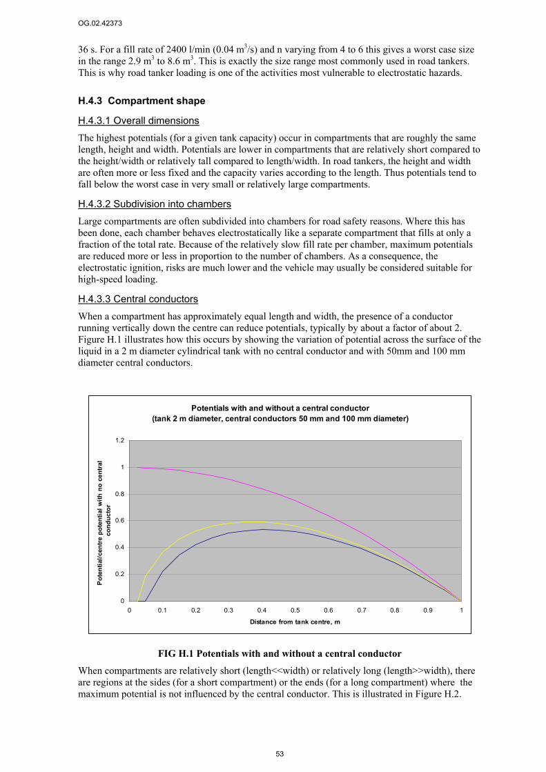
OG.02.42373
53
36 s. For a fill rate of 2400 l/min (0.04 m3/s) and n varying from 4 to 6 this gives a worst case size in the range 2.9 m3 to 8.6 m3. This is exactly the size range most commonly used in road tankers. This is why road tanker loading is one of the activities most vulnerable to electrostatic hazards.
H.4.3 Compartment shape
H.4.3.1 Overall dimensions The highest potentials (for a given tank capacity) occur in compartments that are roughly the same length, height and width. Potentials are lower in compartments that are relatively short compared to the height/width or relatively tall compared to length/width. In road tankers, the height and width are often more or less fixed and the capacity varies according to the length. Thus potentials tend to fall below the worst case in very small or relatively large compartments.
H.4.3.2 Subdivision into chambers Large compartments are often subdivided into chambers for road safety reasons. Where this has been done, each chamber behaves electrostatically like a separate compartment that fills at only a fraction of the total rate. Because of the relatively slow fill rate per chamber, maximum potentials are reduced more or less in proportion to the number of chambers. As a consequence, the electrostatic ignition, risks are much lower and the vehicle may usually be considered suitable for high-speed loading.
H.4.3.3 Central conductors When a compartment has approximately equal length and width, the presence of a conductor running vertically down the centre can reduce potentials, typically by about a factor of about 2. Figure H.1 illustrates how this occurs by showing the variation of potential across the surface of the liquid in a 2 m diameter cylindrical tank with no central conductor and with 50mm and 100 mm diameter central conductors.
FIG H.1 Potentials with and without a central conductor
When compartments are relatively short (length<<width) or relatively long (length>>width), there are regions at the sides (for a short compartment) or the ends (for a long compartment) where the maximum potential is not influenced by the central conductor. This is illustrated in Figure H.2.
Potentials with and without a central conductor(tank 2 m diameter, central conductors 50 mm and 100 mm diameter)
0
0.2
0.4
0.6
0.8
1
1.2
0 0.1 0.2 0.3 0.4 0.5 0.6 0.7 0.8 0.9 1
Distance from tank centre, m
Pote
ntia
l/cen
tre p
oten
tial w
ith n
o ce
ntra
l co
nduc
tor
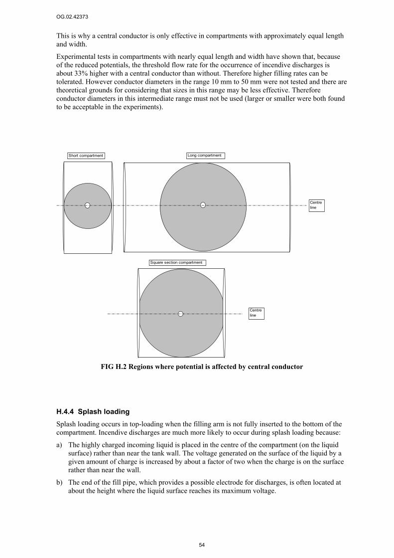
OG.02.42373
54
This is why a central conductor is only effective in compartments with approximately equal length and width.
Experimental tests in compartments with nearly equal length and width have shown that, because of the reduced potentials, the threshold flow rate for the occurrence of incendive discharges is about 33% higher with a central conductor than without. Therefore higher filling rates can be tolerated. However conductor diameters in the range 10 mm to 50 mm were not tested and there are theoretical grounds for considering that sizes in this range may be less effective. Therefore conductor diameters in this intermediate range must not be used (larger or smaller were both found to be acceptable in the experiments).
FIG H.2 Regions where potential is affected by central conductor
H.4.4 Splash loading Splash loading occurs in top-loading when the filling arm is not fully inserted to the bottom of the compartment. Incendive discharges are much more likely to occur during splash loading because:
a) The highly charged incoming liquid is placed in the centre of the compartment (on the liquid surface) rather than near the tank wall. The voltage generated on the surface of the liquid by a given amount of charge is increased by about a factor of two when the charge is on the surface rather than near the wall.
b) The end of the fill pipe, which provides a possible electrode for discharges, is often located at about the height where the liquid surface reaches its maximum voltage.
Long compartmentShort compartment
Centreline
Square section compartment
Centreline
OG.02.42373
55
For these reasons splash loading must be avoided where there is any possibility of a flammable atmosphere (see also Section I.4).
In order to avoid splash loading, the loading-arm drop-tube must reach the bottom of the compartment. As noted in the main text (Section 2.2) this requires that it is:
a) Long enough to reach the bottom of the compartment in all vehicles to be loaded,
b) Fully inserted and
c) Positioned vertically (If a drop-tube does not enter the compartment vertically the end may not reach the base. Typically, if the drop-tube deviates from vertical, the end can be 1/3 of the way up the compartment, even though the arm appears to be fully inserted).
To allow vertical insertion the loading arm must be positioned over the centre of the manlid. Ideally this requires that the swinging horizontal parts of the loading arm are long enough and have enough freedom of movement to reach from the front to the rear manlids on all vehicles. If the horizontal range of the loading arm is too small, it may not be possible to insert the drop tube vertically into both the front and back compartments of long vehicles without moving the vehicle or it may be possible only with very precise vehicle positioning. In these cases drivers must be instructed to reposition the vehicle between loading the front and back compartments to enable the drop tube to be inserted vertically in each. Even when the loading arm is long enough, it is important that the vehicle is parked accurately so that all compartments can be reached with the drop tube vertical.
Top-loading is therefore not considered suitable for high-speed loading unless:
• The loading-arm drop-tube is long enough to reach the bottom of all compartments on all trucks to be loaded.
• The horizontal range of the loading-arm is long enough to enable the drop-tube to be positioned vertically over the centre of all manlids on each truck that is normally to be loaded. The loading arm reach should be long enough to achieve this without the need for unrealistic accuracy in parking the vehicle.
• Drivers are made aware of the importance of avoiding splash loading and of not dropping any items into the compartment during loading.
• Drivers are made aware of the significance of misaligned (non-vertical) fill pipes for splash loading and hence are aware of the need for careful parking to ensure it is always possible to insert the drop tube vertically.
• All vehicles that are too long (in distance between the front and rear compartment manlids) to be comfortably covered by the range of movement of the loading arm must be moved between loading the front and rear compartments to allow vertical insertion of the drop-tube into all compartments.
• Overalls without top pockets must be worn during loading to avoid the risk of dropping items into the compartments.
• Driver performance is monitored by routine spot-checks at an appropriate frequency to ensure timely detection and correction of any malpractice. Particular care should be paid to trucks and drivers new to the gantry.
H.5 Ambient conditions
H.5.1 Temperature Temperature has a significant influence on risks. It affects both the volatility and the electrical conductivity of the product. The volatility affects the flammability of the atmosphere and the conductivity affects the ability of the product to dissipate charge. Conductivity decreases markedly at low temperatures and where there are conductivity targets it is important to ensure that they are met at the lowest temperatures reached by the product during loading.
OG.02.42373
56
H.5.2 Humidity It is often thought that high humidity provides for the dissipation of static charge. This is generally a misconception for liquid handling. Humidity has little effect on the generation or dissipation of charges in liquids.
The misconception probably arises from most people’s experience of static electricity, which is provided for example by school experiments on the charging of solid plastics by flicking them with cats fur. These experiments are strongly influenced by humidity and it is well-known that it is hard to generate any demonstrable level of charge under humid conditions. The role of humidity in this case is to form a conductive film of moisture on the surface of the solid plastic that provides for rapid dissipation. These moisture films do not form on liquid surfaces and a liquid is no more conductive at high humidity than at low. Therefore humidity has little influence on liquid static electricity hazards.
H.6 People and clothing It was noted in the main text that the risks of electrostatic discharge from people may be greater in dry conditions and particularly in cold-dry conditions. To combat this, additional measures may be considered.
The most important supplementary measures are the provision of dissipative footwear and flooring. This combination ensures that the person as a whole is adequately earthed. For dissipative flooring in the present context, a resistance to earth of less than 108 Ω is adequate. Dissipative footwear ensures that a person standing on a conductive or dissipative floor has a resistance to earth of more than 105 Ω but less than 108 Ω.
Many of the conventional flooring materials used in operating environments, for example, bare concrete or steel grids, are conducting enough to be classed as dissipative. However asphalt often is not. In order to remain effective a dissipative floor should not be covered by rubber mats or plastic sheet, etc., and care should be taken to prevent the build-up of contaminants such as resin or other non-conductive substances.
If further protection is sought then the use of dissipative clothing and gloves may also be considered. Dissipative clothing is clothing made from a material with either a surface resistivity of less than 5×10¹⁰ Ω (see EN 1149-1) or good charge decay characteristics (see prEN 1149-3).

OG.02.42373
57
Appendix I: Additional information
I.1 High speed loading compartments A working engineering definition of a high-speed loading compartment for ADR compliant vehicles is given in the main text (Section 2.2). Here we give a more fundamental underlying definition that is not linked to ADR compliance.
To be classed as suitable for high-speed loading, a road tank compartment must have one or more of the following features:
• Length in excess of 4.5 m32.
• The presence of an earthed conductor at, or close to, the centre of the compartment. This may be the loading arm (in top loading), the dip tube (in a compartment so fitted) or a purpose-made central conductor23.
• Division into two or more sub-compartments of nearly equal size by bulkheads that provide good electrostatic shielding whilst having gaps that are large enough for the liquid levels in all sub-compartments to equalise during a fill.
• Top loading compartments can be considered suitable for high speed loading only if there has been a documented risk assessment and procedures have been put in place to ensure splash loading will not occur and that loose items will not be accidentally dropped into the compartments during loading.
I.2 Placement of filters Fine filters (<30 µm) generate much more charge than pipes. To allow this charge to be dissipated before the loading point these filters must be located so that the residence time between the filter outlet and the loading point is at least 54/σ seconds where σ is the lowest possible fuel conductivity that could be encountered in the line in pS/m. This residence time is equivalent to 3τ where τ is the relaxation time (τ=18/σ) associated with the fuel. If the conductivity is unknown or very low, the residence time required by this formula becomes very large. However, it can be shown that it is not necessary to allow more than a maximum of 100 s. A particular warning is given against the use of filter socks on the end of top-loading arms. These are sometimes used when handling extremely conductive chemicals and solvents such as alcohols but they can have very fine pore sizes and their use for low conductivity products has led to at least one accident. There is no residence time available downstream of such devices and therefore they must not be used for low conductivity products such as hydrocarbon fuels.
Moderate filters and strainers (30 µm to 150 µm) also generate more charge than pipework and also need to be located with a residence time of at least 3τ (54/σ) seconds from the loading point. However the charging is less than for fine filters and where the conductivity could be very low there is no need to allow more than a maximum of 30 s of residence time.
32 Although central conductors become less effective in long compartments (see H.4.3.3) it is assumed that the central conductor will be effective for lengths up to about 4.5 m (length to width ratio around 2 for a typical vehicle. This is justified because the declining effectiveness of the central conductor is compensated by the reduced potentials from the increasing compartment length. Above 4.5 m long, the compartment length on its own provides suitability for high speed loading.

OG.02.42373
58
Coarse filters and strainers (>150 µm) are not considered to generate a significant amount of extra charge and there are no specific requirements for their location.
I.3 Earthing 1) The general metalwork of pumps/dispensers etc. must be connected to the earthing of the
associated electrical installation.
2) Pipework should be electrically connected to the tanks. The resistance of the connection path should not exceed 10 Ω. Where bonding conductors are used they must be plastic-covered and terminations should be protected against corrosion and mechanical damage.
3) The bonded tanks and pipes must not be connected directly to the general electrical earthing system because of the possibility of introducing electrical system fault currents via the electrostatic bonding arrangements.
4) Where well-coated underground metal tanks and pipes are employed, an isolating joint (e.g. a plastic insert) must be provided in the pipeline near to each pump/dispenser connection to avoid providing a possible path for electrical fault currents. Such isolating joints will, in any event, be required where tanks and pipework are provided with cathodic protection, which inherently provides a direct connection to the general mass of earth.
5) Instead of direct connection to the general electrical earthing system, the pipes and tanks must be connected to earth by one of the following means:
a) Connection to an earth electrode provided exclusively for the purpose of dissipating electrostatic charge via a plastic-covered copper conductor of not less than 4 mm2 cross-sectional area.
b) Connection to the general electrical earthing arrangements of the installation, via a resistor having a value in the range 105 Ω to 106 Ω and a power rating of not less than 2 W. The connection should use a plastic-covered copper conductor of not less than 4 mm2 cross-sectional area.
c) For isolated well-coated metal tanks and pipes where cathodic protection is not employed, connection to the general electrical earth of the installation via isolating joints that are sufficiently conductive to dissipate electrostatic charge (i.e. joints that have an electrical resistance in the range 105 Ω to 106 Ω).
6) Isolated metal parts on non-conductive tanks and pipework must be electrically bonded together and earthed by one of the following means:
a) Direct connection to an earth electrode exclusive to those parts, for the purpose of dissipating electrostatic charge.
b) Connection via a plastic-covered copper conductor of not less than 4 mm2 cross-sectional area between the bonded isolated metal parts and the general electrical earthing arrangements via a resistor having a value in the range 105 Ω to 106 Ω and a power rating of not less than 2 W (2 watts).
7) Where installations having an existing integrated earthing system are to be segregated, care should be exercised to ensure that each of the segregated installations is within specification after the change.
I.4 Loading arms, top-loading and splash filling Top-loading arms and drop-tubes must be made of a conductive material, preferably metal for robustness. Accidents have occurred where plastic drop tubes have been used. This must not be done.
OG.02.42373
59
Although splash filling must be avoided in top-loading if there could be a flammable atmosphere, it may be acceptable where there is no possibility of a flammable atmosphere (e.g. when loading liquids of low volatility such as luboils that do not produce a flammable vapour atmosphere even at the maximum handling temperature). In this case, however, it is essential to ensure that there are no other sources of flammable vapour and that the loading process does not produce enough mist or suspended droplets to render the atmosphere flammable.
I.5 vd limits
I.5.1 How vd limits arose The use of vd limits began essentially for the following reasons (although maybe the logic was not explicitly stated at the time).
1. There is a threshold potential above which the occurrence of incendive discharges is too frequent to be tolerable.
2. For any given combination of tank conditions, product conductivity etc. there is a maximum tolerable streaming current that can be delivered to the tank before the potential exceeds the threshold.
3. Because the streaming current generated by the flow of liquid through a pipe was once thought to be approximately proportional to (vd)2 the maximum tolerable streaming current was translated to a maximum tolerable value of vd.
4. The vd values required for different combinations of operating conditions were determined by a combination of field trials, experience and experiment.
Later work has suggested that the streaming current probably varies more like v2d than (vd)2 although this is not universally accepted. As vd limits are, by now, a well established approach for setting filling rates, there is not much prospect of agreeing a change of the basis for setting filling rules even if the scientific community were to accept the v2d model. Practically there is not much consequence to keeping vd limits because they are only used for a restricted range of pipe diameters (between 75 mm and 150 mm) and are chosen to give the right empirical result for d= 100 mm. The use of vd limits leads to slightly increased risk (high velocity) in small diameter systems (d<100 mm) and slightly reduced risk (low velocity) in large diameter systems (d>100 mm).
I.5.2 Background to vd limits for particular operations
I.5.2.1 Top-loading
Originally (1970s), Shell advised vd≤0.5 m2/s for top-loading and BP advised vd<0.38 m2/s unless the conductivity was known to be more than 5 pS/m. As conductivity was never measured, the BP recommendation essentially reduced to a universal vd≤0.38 m2/s. There was debate about which value was right and no general industry agreement. Codes of practice at the time (e.g. BS 5958) mentioned both figures.
In the 1980s, following the Avonmouth and Plymouth incidents, Shell revised its top-loading guidance to vd≤0.38 m2/s. The grounds for this were that, whilst there was confidence that vd≤0.5 m2/s was the appropriate limit for top-loading carried out in exact accordance with recommended practice, it was, in reality, very hard to be sure that splash loading would never occur (splash loading was certainly an issue in the Plymouth incident). The move to the lower limit was made to counteract this extra risk. This is the rule that people within Shell have become used to for top-loading prior to this Safety Advice.
Other oil companies (Esso/Exxon in particular) have not agreed that vd≤0.38 m2/s is warranted for top loading. Their stance is that you should control (eliminate) splash loading and apply the higher limit. They think they can eliminate splash loading. To accommodate both viewpoints, industry guidance (IP, CENELEC) advocates vd≤0.5 m2/s as the key limit but advises considering
OG.02.42373
60
vd≤0.38 m2/s unless the site management are completely sure that splash loading can be eliminated. We have adopted this approach in the present Safety Advice in order to maintain compatibility with the external advice. This gives some relaxation from the top-loading rules that people within Shell have previously been used to.
I.5.2.2 Bottom loading When bottom loading was introduced, the limits were adapted from top-loading. The top-loading figure of vd≤0.5 m2/s was retained for compartments with a central conductor (dip tube). A reduced limit of vd≤0.38 m2/s was adopted for compartments without a dip tube. The reduction is needed because, for a given charge density in the compartment, potentials are about 70% higher when there is no conductor (e.g. a dip tube or filling arm) in the middle of the tank (see H..4.3.3).
I.5.2.3 Low sulphur diesel Recently, concern about accidents prompted an investigation of the additional risks associated with low sulphur (<50 ppm) diesel. Analysis of the accident record showed that, for standard loading conditions, the risk of ignition with low sulphur diesel is higher than with standard diesel by about a factor of 30. It is thought that the risk increase arises from hydrotreatment and that it probably applies to all middle distillate products.
Shell data from the 1980s has been used to estimate what reduction in vd limit is needed to counteract the increased ignition risk. It was found that vd≤0.35 m2/s for low sulphur products gives the same estimated level of risk as does vd≤0.5 m2/s for standard products. Similarly vd≤0.25 m2/s for low sulphur products gives the same level of risk as vd≤0.38 m2/s for standard products. These limits are used in the present Safety Advice for low sulphur middle distillates of uncontrolled conductivity. This is compatible with IP, CENELEC etc.
Risks may also be reduced by ensuring a minimum conductivity. If it can be ensured that the conductivity exceeds 10 pS/m, the risks associated with low sulphur products are the same as or less than the risks associated with standard products of uncontrolled conductivity. Thus when the conductivity is controlled, the additional velocity are not needed (see Figure 1).
I.5.2.4 Gasoline loading Gasoline composition and processing are very different from the middle distillate equivalents and there is no evidence of increased electrostatic ignition risks with low sulphur gasolines. Thus the base-case for gasoline loading is the standard one of vd≤0.5 m2/s for compartments suitable for high-speed loading and vd≤0.38 m2/s for compartments not suitable for high-speed loading. The following argument, based on the normal over-richness of gasoline vapour, can be used, however, to show that it is acceptable to simplify this and use vd≤0.5 m2/s for all gasoline loading.
Gasoline loading generally produces an over-rich atmosphere in much of the compartment and the atmosphere near the liquid surface is almost always over-rich even though, with top-loading in particular, there is a flammable zone around the opening. The sparks produced by static electricity when loading according to vd≤0.5 m2/s are only a few cm long at most, thus the static ignition risk is confined to a thin layer close to the surface. It is therefore very unlikely that a static electricity spark will occur in a flammable region during gasoline loading.
Although accidents have been reported in gasoline loading, there are significantly fewer than in middle distillate loading. An API survey covering the period before 1982, reported 39 middle-distillate incidents and just 4 gasoline incidents33. Recently the gasoline market in the USA has been about double the size of the middle distillate market. At the time of the survey relatively more gasoline was sold. Thus the risk per fill at the time of the survey was probably more than 20 times higher with middle distillates than with gasoline. There were no specific differences in loading rate recommended for the two product classes. The increase in risk associated with changing the vd limit from vd≤0.38 m2/s to vd≤0.5 m2/s is estimated to be about a factor of 20. Thus the risk in
33 Incidents associated with earthing faults are not included in these numbers as they cannot be controlled by flow rate limits.
OG.02.42373
61
loading gasoline at vd≤0.5 m2/s is approximately the same as loading a middle distillate at vd≤0.38 m2/s.
Against this background it is judged to be acceptable to load gasoline at vd≤0.5 m2/s into compartments that are not suitable for high speed loading.
By the same argument, compartments that are suitable for high speed loading could be loaded up to a higher limit than vd≤0.5 m2/s. However as there is no demand for such very high speed loading we suggest simplifying the rules for gasoline to an overall limit of vd≤0.5 m2/s irrespective of the geometry of the compartment (i.e. for gasoline, all compartments can be considered suitable for high speed loading). This is the approach that is adopted in this Safety Advice. It is not currently the advice offered by the IP or CENELEC who treat gasoline loading and middle distillate loading in the same way apart from the influence of sulphur content. We shall, however, be lobbying for a modification to the gasoline filling rules on the basis of the arguments just presented.
If there are circumstances in which a higher than normal risk is perceived (e.g. if the melting of winter ice produces an increased risk of water in the system), then additional precautions should be taken such as reducing loading rates below the standard limits or raising the conductivity with SDA. The extra precautions should be used for both middle distillates and gasolines.
I.5.2.4 Rail tanker loading Because rail tankers are larger than road tankers they take longer to fill and there is more time for relaxation during filling. This allows higher vd limits to be used. The standard value for rail tanker loading is vd≤0.75 m2/s. The loading of low sulphur diesel into rail tankers has not been explicitly studied but a reduced rate has been derived by assuming that the vd limit should be reduced in the same proportion as for road tanker loading. With this assumption, the rail tanker loading rate for low sulphur middle distillates is given by vd≤0.53 m2/s.


OG.02.42373
63
Appendix J: Flow rate tables and vd equivalents
This information is based on standard weight (schedule 40) pipeline size. NB=Nominal Bore (in mm) and ID=Inside Diameter (in mm).
Table J.1 Flow rates in cubic metres per hour for different flow speeds and pipe diameters
Flow speed, m/s
1 2 3 4 5 6 7
NB ID Volume, l/m Flow rate, m³/hr
38 40.94 1.3 5 9 14 19 24 28 33
50 52.48 2.2 8 16 23 31 39 47 55
65 62.68 3.1 11 22 33 44 56 67 78
80 77.92 4.8 17 34 52 69 86 103 120
100 102.36 8.2 30 59 89 118 148 178 207
150 154.08 18.6 67 134 201 269 336 403 470
200 202.74 32.3 116 232 349 465 581 697 814
250 254.56 50.9 183 366 550 733 916 1099 1283
300 304.8 73.0 263 525 788 1051 1313 1576 1839
350 336.5 88.9 320 640 960 1281 1601 1921 2241
400 387.3 117.8 424 848 1272 1696 2121 2545 2969
Table J.2 Flow rates in litres per minute for different flow speeds and pipe diameters
Flow speed, m/s
1 2 3 4 5 6 7
NB ID Volume, l/m Flow rate, l/min
38 40.94 1.3 79 158 237 316 395 474 553
50 52.48 2.2 130 260 389 519 649 779 909
65 62.68 3.1 185 370 555 741 926 1111 1296
80 77.92 4.8 286 572 858 1144 1431 1717 2003
100 102.36 8.2 494 987 1481 1975 2469 2962 3456
150 154.08 18.6 1119 2238 3356 4475 5594 6713 7831
200 202.74 32.3 1937 3874 5811 7748 9685 11622 13559
250 254.56 50.9 3054 6107 9161 12215 15268 18322 21376
300 304.8 73.0 4378 8756 13134 17512 21890 26268 30646
350 336.5 88.9 5336 10672 16008 21344 26680 32016 37352
400 387.3 117.8 7069 14137 21206 28275 35343 42412 49481

OG.02.42373
64
Table J.3 Flow velocities corresponding to the vd limits used in this guide for different pipe sizes (subject to an overall 7 m/s limit)
Nominal bore, mm 38 50 65 80 100 150 200 250 300 350 400
vd, m2/s
Velocity corresponding to vd limit, m/s
0.25 6.1 4.8 4.0 3.2 2.4 1.6 1.2 1.0 0.8 0.7 0.6 0.35 7.0 6.7 5.6 4.5 3.4 2.3 1.7 1.4 1.1 1.0 0.9 0.38 7.0 7.0 6.1 4.9 3.7 2.5 1.9 1.5 1.2 1.1 1.0 0.5 7.0 7.0 7.0 6.4 4.9 3.2 2.5 2.0 1.6 1.5 1.3 0.53 7.0 7.0 7.0 6.8 5.2 3.4 2.6 2.1 1.7 1.6 1.4 0.75 7.0 7.0 7.0 7.0 7.0 4.9 3.7 2.9 2.5 2.2 1.9
Table J.4 Volumetric flow rates corresponding to the vd limits used in this guide for different pipe sizes (subject to an overall 7 m/s limit)
Nominal bore, mm 38 50 65 80 100 150 200 250 300 350 400
vd, m2/s
Flow rates corresponding to vd limit, litres/min
0.25 482 618 738 918 1206 1815 2388 2999 3591 3964 4563 0.35 553 866 1034 1285 1688 2541 3344 4199 5027 5550 6388 0.38 553 909 1122 1395 1833 2759 3630 4558 5458 6026 6935 0.5 553 909 1296 1836 2412 3630 4777 5998 7182 7929 9126 0.53 553 909 1296 1946 2557 3848 5064 6358 7613 8404 9673 0.75 553 909 1296 2003 3456 5446 7165 8997 10773 11893 13688
Notes:
1) The flow rates given in Table J.4 are rounded to the nearest integer value. The accuracy of the risk assessments scarcely warrants this level of precision so the values given in the main text are rounded to a multiple of 50. They are rounded down if the remainder is between 0 and 40 and up if it is between 40 and 50.
2) Data are given for pipes up to 400 mm for completeness. The vd limits apply only to truck or rail tanker loading which are unlikely to involve pipes greater than 150 mm or 200 mm.

OG.02.42373
65
FIG J.1 Maximum permissible flow velocity as a function of vd limit (and subject to overall 7 m/s limit) for different pipe sizes
FIG J.2 Maximum permissible flow rate as a function of vd limit (including influence of overall 7 m/s limit) for different pipe sizes
0
1
2
3
4
5
6
7
8
0 0.1 0.2 0.3 0.4 0.5 0.6 0.7 0.8
vd limit, m2/s
Velo
city
lim
it, m
/s
NB=38 NB=50 NB=65 NB=80 NB=100
NB=150
NB=200NB=250NB=300NB=350NB=400
0
1000
2000
3000
4000
5000
6000
7000
8000
9000
10000
0 0.1 0.2 0.3 0.4 0.5 0.6 0.7 0.8vd limit, m2/s
Flow
rate
lim
it, l/
min
NB=38NB=50NB=65
NB=80
NB=100
NB=150
NB=200
NB=250
NB=300NB=350NB=400


OG.02.42373
67
Appendix K : Plastic materials
K.1 Definitions Conductive: Will not retain a significant electrostatic charge when in contact with earth and can transmit electric shocks from power systems. These materials have a volume resistivity lower than or equal to 104 Ωm (for certain items e.g. conductive hose there are special definitions)
Dissipative (previously known as anti-static): Will not retain a significant amount of electrostatic charge when in contact with earth but too resistive to transmit electric shocks from power systems. These materials have a volume resistivity higher than 104 Ωm but equal to or lower than 109 Ωm, or a surface resistivity less than 1010 Ω (or surface resistance less than 109 Ω) measured at ambient temperature and 50 % relative humidity.
Non-conductive (insulating): Neither conductive nor dissipative. Electrostatic charges can accumulate and will not readily dissipate even if part of the material is in contact with earth. These materials have a volume resistivity higher than 109 Ωm, and a surface resistivity more than 1010 Ω (or a surface resistance more than 109 Ω) measured at ambient temperature and 50 % relative humidity. Most common plastics are insulating.
K.2 Size Limits Large areas of plastic can hold enough charge to produce electrostatic discharges capable of igniting flammable materials. To avoid this possibility it is essential that where non-conductive plastics are used in hazardous areas at locations where the plastic could be subject to charging mechanisms (e.g. liquid flow or rubbing) the plastics must not exceed certain size limits. These limits must be adopted unless it can be shown that hazardous electrostatic charges are not to be expected and that charging mechanisms will not occur at any time.
The nature of the size limit depends on the shape of the surface as follows:
a) for sheet materials the limit is defined in terms of the exposed (chargeable) area,
b) for curved objects the limit is defined in terms of the projection of the object that gives the maximum area,
c) for long narrow materials, such as cable sheaths or pipes, the limit is defined as the transverse dimension (i.e. the diameter for a cable sheath or pipe). When the object is coiled it should be treated as a sheet (see item a).
The restrictions depend on the ignitability of the gases and vapours (expressed by the assignment to Group IIA, IIB or IIC, see EN 50014) and the classification of the hazardous area (Zone 0, 1 or 2). Petroleum fuels belong to Group IIA. The Zone 0, 1 and 2 size limits for Group IIA materials are given in Table K.1.
Table K.1 Restriction on size of non-conductive plastics in hazardous areas containing potentially flammable atmospheres of group IIA
Zone Maximum area, cm2 Maximum width, cm
0 50 0.3
1 100 3.0
2 No limit No limit
A sheet of insulating plastic that exceeds the size limits given in Table K.1 may be used if it is subdivided into smaller areas by a closed mesh or grid of earthed conductive or dissipative material at or near the plastic surface. In this case, the maximum area of any cell in the mesh must not exceed 4 times the areas given in Table K.1. (Mesh cell areas can be larger than the areas of isolated pieces of plastic because the presence of the earthed mesh holds potentials down.)


OG.02.42373
69
Appendix L: Contacts
The Fuels Business Group Technical Service Team (Shell GS OGMF/0, CIP, U.K.) may be contacted on:
Tel. +44 (0)151 373 5952 Fax.+44 (0)151 373 5269
Shell GS Oil and Gas Logistics, Crude Oil and Product Quality Group may be contacted on:
Tel. +31 (0)70 377 6268 Fax.+31 (0)70 377 2943,
email. [email protected]
STASCO advisor (OTS/41, Strand, London, U.K.) may be contacted on:
Tel. +44 (0)20 7546 2453.

OG.02.42373 CONFIDENTIAL
71
Administration Page Report Type: Report for publication
Report Number: OG.02.42373
Title: Safety Advice: Precautions against electrostatic ignitions when loading vehicles with bulk fuels
Issue Date: December 2002
Author(s): H.L.Walmsley
Issuing Group: OGMF/2
Contributor(s): -
Reviewed by: M.Brown OGMF/2
Owner / Custodian: L.Clarke- OGMF/0 responsible for approving contents and distribution of report
Project / Budget: SIPC: SHS-Static distrib guid
Activity Code: 53007258
Sponsor / Customer: SIPC -OXD/1 and -OMF/3
Contract Reference: -
Keywords: Static electricity, distribution, vehicle loading, safety advice, petroleum fuels
Electronic File:
Issuing Library: Shell Global Solutions (UK), Cheshire Innovation Park, OGUK-OGXI (Reports Library)
Ownership and Copyright: This document is made available subject to the condition that the recipient will neither use nor disclose the contents except as agreed in writing with the copyright owner. Copyright is vested in Shell Global Solutions International B.V., The Hague.
© Shell Global Solutions International B.V., 2003. All rights reserved.
Neither the whole nor any part of this document may be reproduced or distributed in any form or by any means (electronic, mechanical, reprographic, recording or otherwise) without the prior written consent of the copyright owner.
Security Classification: This is a document. Reference to this document should only be made in documents having the same, or higher, security classification.
Additional distribution: Any distribution beyond the parties listed must be authorised by the owner/custodian.
Restrictions on distribution: None
Original Distribution: Shell Global Solutions (UK), Cheshire Innovation Park OGUK-OGXI Reports Library
OGUK-OGMF M. Booth OGUK-OGMF/2 Sara Lawrence
OGUK-OGMF/2 L.Clarke
SIPC, Shell Centre, London
SIPC-OGUK-OGLD/2 D.Wellington
SIPC-OMF/3 S.Kempsell
Report No: .OG.02.42373Confidential
Safety Advice: Precautions against electrostatic ignitions when loading vehicles with bulk fuels


Report No: .OG.02.42373Confidential
This document is made available subject to the condition that the recipient will neither use nor disclose the contents except as agreed in writing with the copyright owner. Copyright is vested in Shell Global Solutions International B.V., The Hague.
© Shell Global Solutions International B.V., 2003. All rights reserved.
Neither the whole nor any part of this document may be reproduced or distributed in any form or by any means (electronic, mechanical, reprographic, recording or otherwise) without the prior written consent of the copyright owner.
This document is . Any distribution beyond the parties listed must be authorised by the owner/custodian. Reference to this document should only be made in documents having the same, or higher, security classification.
Restrictions: