safe work practices on high voltage overhead lines€¦ · title: safe work practices on high...
TRANSCRIPT

Title: Safe Work Practices on High Voltage Overhead Lines Revision: 1 Page 1 of 32
Safe Work Practices on High Voltage Overhead Lines
Document Summary
This document supports the Power System Safety Rules and its requirements assembled under Overhead Lines and Equipment - Category 6 and describe safe work practices to be followed for the treatment of hazardous situations.
It applies to work practices on all overhead lines and associated apparatus including overhead lines within a substation.
Document Number: GD SR G3 162
Revision: 1
Revision Approval Date: 23 December 2013
Prepared by: J. Mason Safety Rules Coordinator
Reviewed by: B. Fraser Mains Manager / NS&O / Northern Region
T. Howard Process & Systems Manager / NS&O / Southern Region
M. Hoarau Mains Manager / NS&O / Central Region
R. Strobel Mains Manager / NS&O / Southern Region
Approved:
N. Smith General Manager / System Operations
Re-Issued Date: 23 December 2013
A paper copy of this document may be uncontrolled. Please verify it is the latest revision before use by referring to the Wire/Document Centre/Policies & Procedures/Corporate Procedures
Title: Safe Work Practices on High Voltage Overhead Lines Revision: 1 Page 2 of 32
Table of Contents
1. Overview ....................................................................................................................................... 3
1.1 Purpose .................................................................................................................................... 3 1.2 Policy Base ............................................................................................................................... 3 1.3 Reference Documents.............................................................................................................. 3 1.4 Scope ....................................................................................................................................... 3 1.5 Role and Responsibilities ......................................................................................................... 3 1.6 Document Location .................................................................................................................. 3
2. Introduction .................................................................................................................................. 4
3. Overhead Line Hazardous Situations........................................................................................ 5
4. Safe Work Practices .................................................................................................................... 7
4.1 Identification of High Voltage Feeders ..................................................................................... 7 4.1.1 General Procedures for work on all Double Circuit lines .................................................... 7 4.1.2 Identifying the live circuit on a double circuit tower ............................................................. 8 4.1.3 Identifying the live circuit on a single pole structure............................................................ 9 4.1.4 Identifying the live circuit on a double wood pole structure .............................................. 10 4.2 Persons to Keep Clear of Equipment ..................................................................................... 11 4.3 Persons Working at Ground Level ......................................................................................... 11 4.3.1 Persons Working at Ground Level (Other than on Conductors) ....................................... 11 4.3.2 Persons Working on Conductors at Ground Level............................................................ 12 4.3.3 Safeguards for Persons While Working at Ground Level ................................................. 12 4.3.4 Handling Overhead line Conductors at Ground Level (Insulated Work Methods) ............ 14 4.4 Persons Working Aloft ............................................................................................................ 16 4.4.1 Bonded Work Spaces Aloft ............................................................................................... 16 4.4.2 Bonded Work Space –Steel Tower ................................................................................... 16 4.4.3 Bonded Work Space – Wood Pole Structure .................................................................... 17 4.4.4 Bonded Work Space – Elevated Work Platform ............................................................... 18 4.4.5 Insulated Working from an Insulated Elevating Work Platform ......................................... 19 4.5 Making or Breaking Connections on High Voltage Overhead Lines ...................................... 20 4.5.1 Application of a Bridging Lead .......................................................................................... 20 4.6 Large Work Sites .................................................................................................................... 20 4.7 Stringing an Overhead Line Parallel to an In-Service Line .................................................... 20 4.7.1 Work Areas and Equipment .............................................................................................. 20 4.7.2 Standard Safeguards to be applied for Stringing Operations ........................................... 21 4.8 Stringing Conductor on Landing Span to HV Substations ..................................................... 23 4.8.1 Standard Safeguards ........................................................................................................ 23 4.8.2 Outline of Procedure for Stringing landing Spans ............................................................. 24 4.8.3 Special Circumstances ...................................................................................................... 27 4.9 Testing of HV Overhead Lines - Safeguards for Use of Test Instruments ............................. 28
5. Amendments to Previous Issue ............................................................................................... 29
6. Attachment A- Insulating Boots, Gloves and Sheet .............................................................. 30
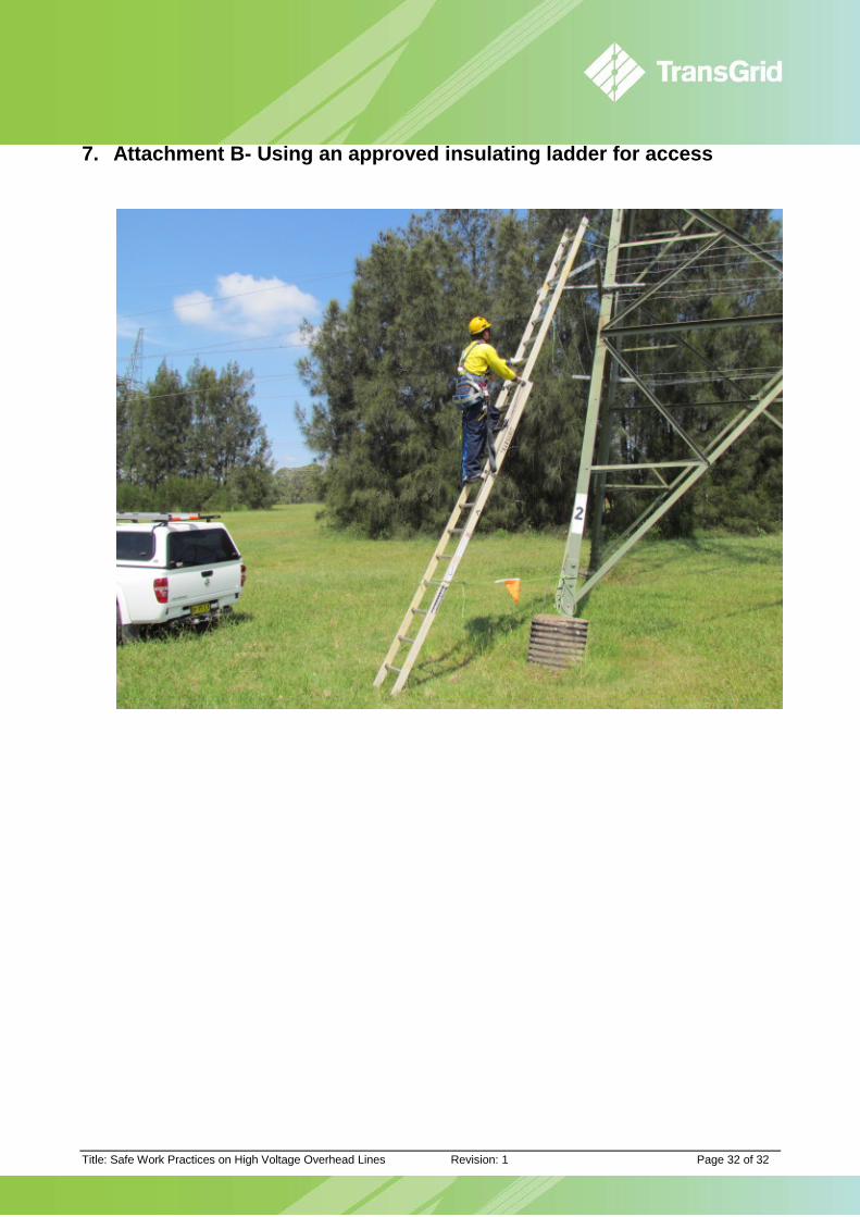
7. Attachment B- Using an approved insulating ladder for access ......................................... 32

Title: Safe Work Practices on High Voltage Overhead Lines Revision: 1 Page 3 of 32
1. Overview
1.1 Purpose This document supports the Power System Safety Rules and its requirements assembled under Overhead Lines and Equipment - Category 6 and describe safe work practices to be followed for the treatment of hazardous situations.
1.2 Policy Base Document No. Document
GD SR G1 100 Power System Safety Rules
1.3 Reference Documents Document No. Document
Proving High Voltage Conductors De-energised
Portable Earthing of High Voltage Conductors
1.4 Scope This standard applies to work practices on all overhead lines and associated apparatus including overhead lines within a substation.
1.5 Role and Responsibilities Responsible person Responsibility
EGM – NS&O Maintenance and ownership of this standard
Mgr – Training Implementation of this standard
Authorised persons Comply with this standard
1.6 Document Location Block diagram showing location of document in relation to others.
Operating Process for Access to HV Apparatus
Power System Safety Rules
Category 5 Category 6 Category 7
Access for Work on HV Substation
Apparatus
Safe Work Practices on HV Overhead Lines
Safe Work Practices on HV
Cables
Supporting Documentation
ProceduresAccess for Work on HV Overhead
Lines
Access for Work on HV
Transmission Cables
Work
Instructions
Safe Work Practices on HV
Substation Apparatus

Title: Safe Work Practices on High Voltage Overhead Lines Revision: 1 Page 4 of 32
2. Introduction This standard was developed as a guide to assist in selecting the correct safe work practices to be used when preforming work on overhead lines. Work may only commence on an overhead line when it has been made safe for work and an access authority has been issued.
The safe work practices contained within this document protect staff from the hazardous occurrences or effects that can develop on or around overhead lines and their support structures, including:
• Lightning; • Induced voltages and currents; • Transfer Voltages; • Voltage Gradients; • Line Energising; and • Neutral and Earthing System Currents
This document sets out a range of hazardous situations, the controls (safeguards) to be implemented and describes the safe work practices which must be observed. The possible safe work practices are referenced for each situation.
This document should be read in conjunction with Portable Earthing of High Voltage Conductors. This document indicates when various practices should be used and indicates what hardware should be used when implementing the nominated practices.
It is the responsibility of all employees engaged in work on high voltage overhead lines to follow all the safe work practices applicable to the work.
These safe work practices are to be used in conjunction with TransGrid’s Health and Safety Risk Assessment process. The process may identify that additional controls are required for particular tasks and situations.
Title: Safe Work Practices on High Voltage Overhead Lines Revision: 1 Page 5 of 32
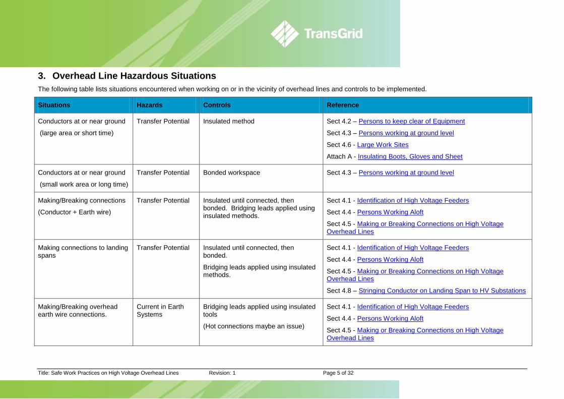
3. Overhead Line Hazardous Situations The following table lists situations encountered when working on or in the vicinity of overhead lines and controls to be implemented.
Situations Hazards Controls Reference
Conductors at or near ground
(large area or short time)
Transfer Potential Insulated method Sect 4.2 – Persons to keep clear of Equipment
Sect 4.3 – Persons working at ground level
Sect 4.6 - Large Work Sites
Attach A - Insulating Boots, Gloves and Sheet
Conductors at or near ground
(small work area or long time)
Transfer Potential Bonded workspace Sect 4.3 – Persons working at ground level
Making/Breaking connections
(Conductor + Earth wire)
Transfer Potential Insulated until connected, then bonded. Bridging leads applied using insulated methods.
Sect 4.1 - Identification of High Voltage Feeders
Sect 4.4 - Persons Working Aloft
Sect 4.5 - Making or Breaking Connections on High Voltage Overhead Lines
Making connections to landing spans
Transfer Potential Insulated until connected, then bonded.
Bridging leads applied using insulated methods.
Sect 4.1 - Identification of High Voltage Feeders
Sect 4.4 - Persons Working Aloft
Sect 4.5 - Making or Breaking Connections on High Voltage Overhead Lines
Sect 4.8 – Stringing Conductor on Landing Span to HV Substations
Making/Breaking overhead earth wire connections.
Current in Earth Systems
Bridging leads applied using insulated tools
(Hot connections maybe an issue)
Sect 4.1 - Identification of High Voltage Feeders
Sect 4.4 - Persons Working Aloft
Sect 4.5 - Making or Breaking Connections on High Voltage Overhead Lines
Title: Safe Work Practices on High Voltage Overhead Lines Revision: 1 Page 6 of 32
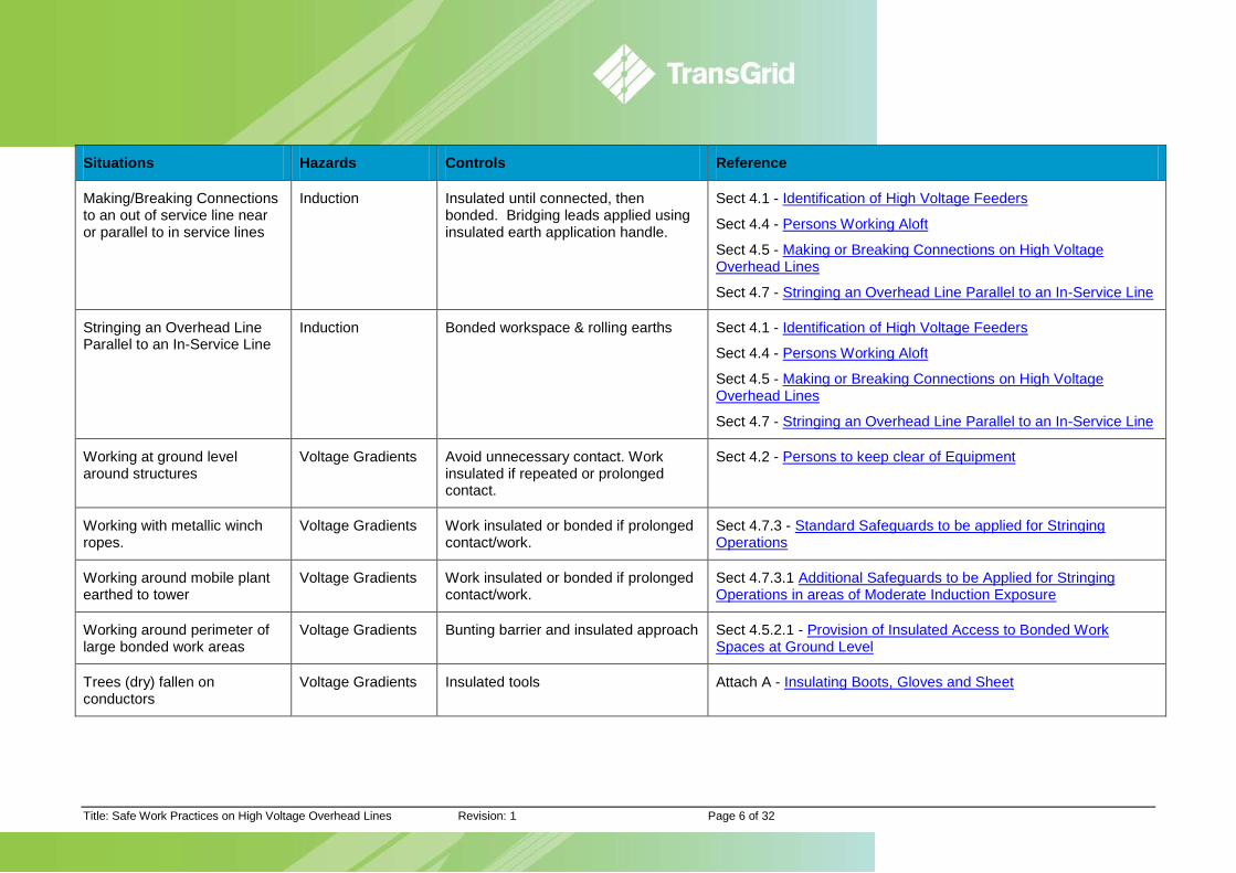
Situations Hazards Controls Reference
Making/Breaking Connections to an out of service line near or parallel to in service lines
Induction Insulated until connected, then bonded. Bridging leads applied using insulated earth application handle.
Sect 4.1 - Identification of High Voltage Feeders
Sect 4.4 - Persons Working Aloft
Sect 4.5 - Making or Breaking Connections on High Voltage Overhead Lines
Sect 4.7 - Stringing an Overhead Line Parallel to an In-Service Line
Stringing an Overhead Line Parallel to an In-Service Line
Induction Bonded workspace & rolling earths Sect 4.1 - Identification of High Voltage Feeders
Sect 4.4 - Persons Working Aloft
Sect 4.5 - Making or Breaking Connections on High Voltage Overhead Lines
Sect 4.7 - Stringing an Overhead Line Parallel to an In-Service Line
Working at ground level around structures
Voltage Gradients Avoid unnecessary contact. Work insulated if repeated or prolonged contact.
Sect 4.2 - Persons to keep clear of Equipment
Working with metallic winch ropes.
Voltage Gradients Work insulated or bonded if prolonged contact/work.
Sect 4.7.3 - Standard Safeguards to be applied for Stringing Operations
Working around mobile plant earthed to tower
Voltage Gradients Work insulated or bonded if prolonged contact/work.
Sect 4.7.3.1 Additional Safeguards to be Applied for Stringing Operations in areas of Moderate Induction Exposure
Working around perimeter of large bonded work areas
Voltage Gradients Bunting barrier and insulated approach Sect 4.5.2.1 - Provision of Insulated Access to Bonded Work Spaces at Ground Level
Trees (dry) fallen on conductors
Voltage Gradients Insulated tools Attach A - Insulating Boots, Gloves and Sheet
Title: Safe Work Practices on High Voltage Overhead Lines Revision: 1 Page 7 of 32
4. Safe Work Practices Safe work practices are applicable to all overhead line working situations and are to be used (as applicable) for all overhead line work.
It is essential when developing safe working procedures to carefully assess the possibility of hazardous voltage rises occurring at the work site and where appropriate, give consideration to the following basic safe working practices and safeguards.
These safeguards (controls) are to be used in conjunction with TransGrid’s Health and Safety Risk Assessment.
4.1 Identification of High Voltage Feeders High Voltage Overhead Line structures are identified by a feeder identification number and structure identification numbers e.g. 30/247 where 30 refers to the overhead line identification number and 247 refers to the structure number.
Double circuit towers have an identification number for each circuit, clearly marked on the appropriate legs of the tower, so that the circuit can be positively identified.
4.1.1 General Procedures for work on all Double Circuit lines
For persons working aloft it is essential to identify the circuit on which work is to be carried out. Identification is assisted by the presence of Access Authority Earths on the isolated circuit.
For persons working at ground level there is a significant hazard from fall ropes which may inadvertently come dangerously close to the live circuit. The procedures detailed below have been developed to minimise the hazard to persons working at ground level as well as providing additional indication of live conductors to persons working aloft:
(a) Ensure that the overhead line description given by the Controller agrees with that on the Request for Access and the identification number on the overhead line structure.
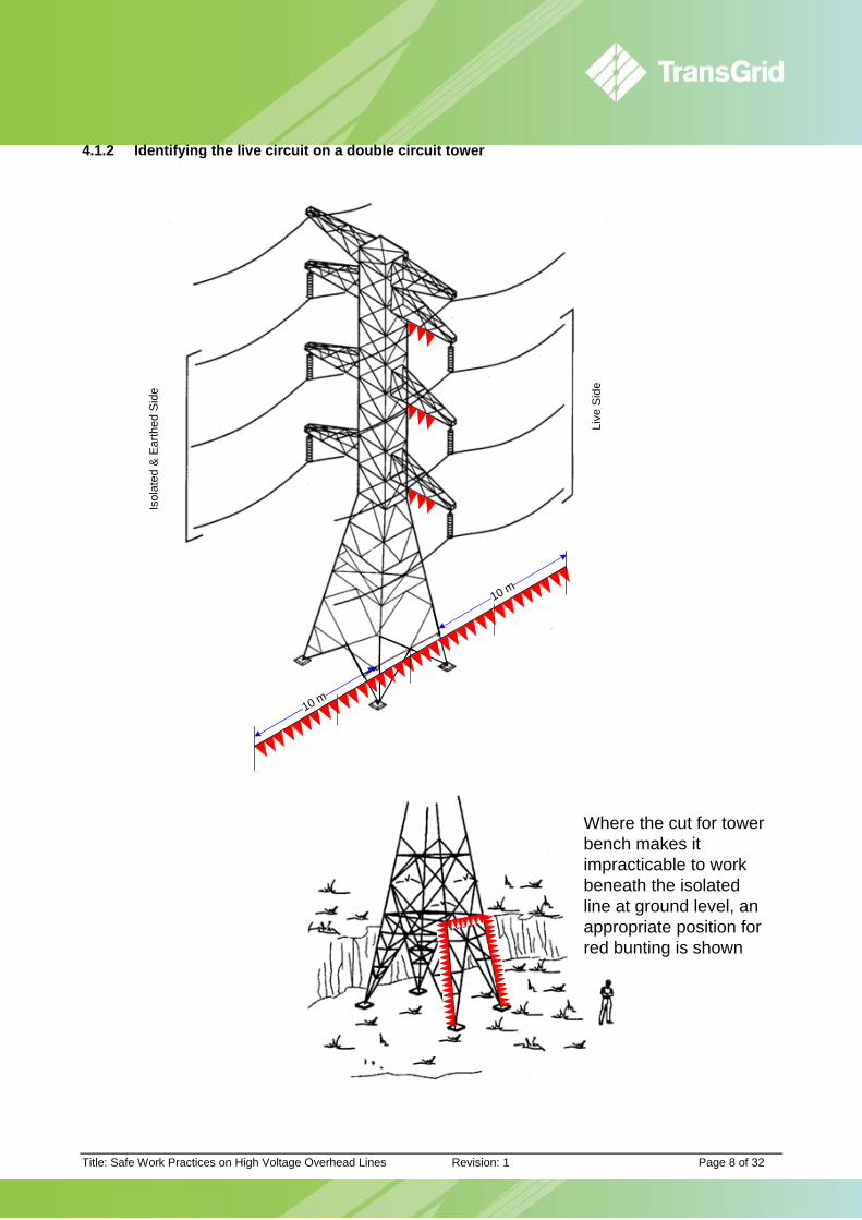
(b) After the circuit has been proved de-energised and Access Authority Earths applied, the in-service side of the double circuit structure is to be identified by a barrier of red flag bunting, set up to extend approximately 10 metres from, and on each side of the structure running parallel to the conductors. Red flags or bunting shall also be draped at the junction of the structure body and each of the three cross-arms of the live circuit in order to clearly indicate the live circuit. Where the climbing pegs and ladder support are on the in-service side of the structure, an opening may be provided in the barrier to allow access to the foot of the ladder.
(c) All plant and equipment on the ground and aloft are to be confined to the side of the structure on which work is being carried out. Where this is impracticable the person in charge of the work shall nominate a person to be a safety observer.
(d) All conducting fall ropes from the structure to the ground shall be brought through snatch blocks near ground level on the side of the structure on which work is being performed.
Sections 4.1.2, 4.1.3 & 4.1.4 show the arrangement of the red bunting and/or flags on double circuit overhead line steel towers, steel poles and wood poles, respectively.
Insets to these sketches show the arrangement of red flag bunting which may be used where the nature of the terrain makes it impracticable to set out the barrier of red flag bunting indicated below.
Title: Safe Work Practices on High Voltage Overhead Lines Revision: 1 Page 8 of 32
4.1.2 Identifying the live circuit on a double circuit tower
10 m
10 m
Isol
ated
& E
arth
ed S
ide
Live
Sid
e
Where the cut for tower bench makes it impracticable to work beneath the isolated line at ground level, an appropriate position for red bunting is shown
Title: Safe Work Practices on High Voltage Overhead Lines Revision: 1 Page 9 of 32
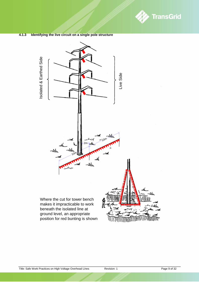
4.1.3 Identifying the live circuit on a single pole structure
Where the cut for tower bench makes it impracticable to work beneath the isolated line at ground level, an appropriate position for red bunting is shown
10m
10m2m
Isol
ated
& E
arth
ed S
ide
Live
Sid
e
Title: Safe Work Practices on High Voltage Overhead Lines Revision: 1 Page 10 of 32
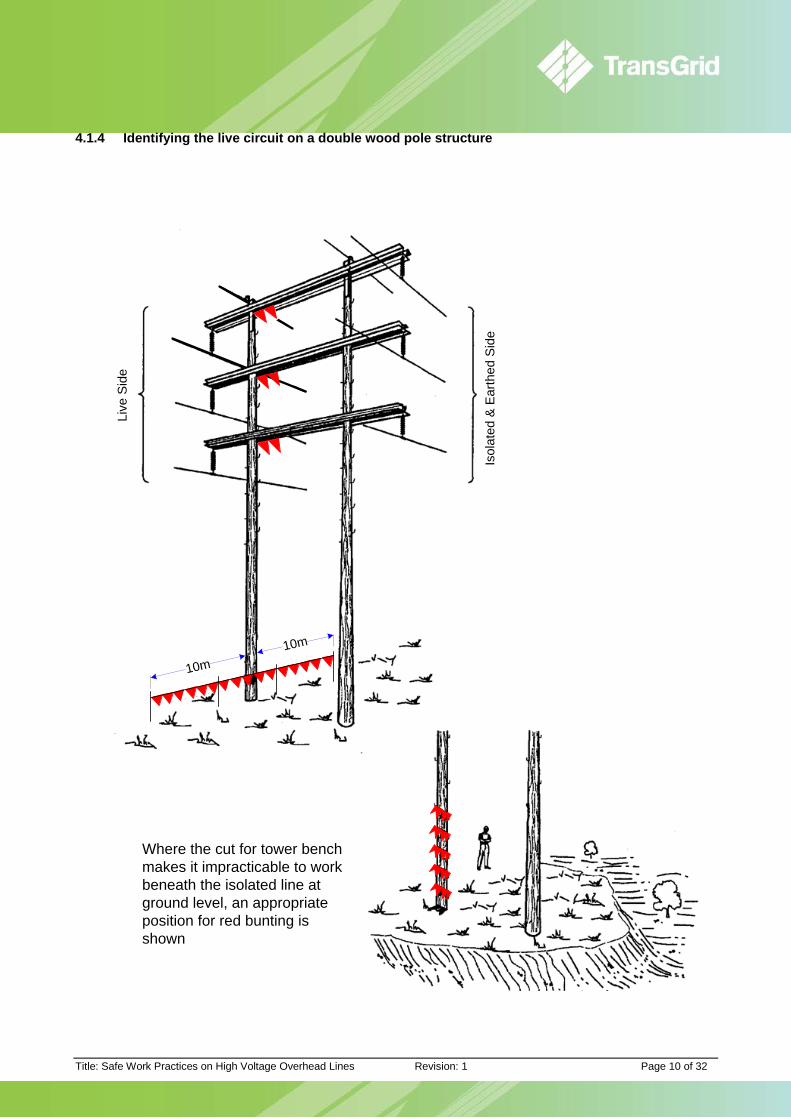
4.1.4 Identifying the live circuit on a double wood pole structure
Where the cut for tower bench makes it impracticable to work beneath the isolated line at ground level, an appropriate position for red bunting is shown
Isol
ated
& E
arth
ed S
ide
Live
Sid
e
10m10m

Title: Safe Work Practices on High Voltage Overhead Lines Revision: 1 Page 11 of 32
4.2 Persons to Keep Clear of Equipment Workers engaged in work on HV overhead lines shall ensure that all persons: (a) Keep clear (at least 3 metres) of structures, plant, and equipment associated with the work. (b) Directly engaged in the work are aware of the specific safeguards applying to the work; and (c) Keep clear of and do not touch conductor near the ground, unless under insulated working
conditions or under bonded work area conditions.
4.3 Persons Working at Ground Level 4.3.1 Persons Working at Ground Level (Other than on Conductors)
For persons working at ground level, other than on conductors, it is essential that:
(a) Safety boots are worn; (b) In wet conditions ‘Wellington‘ type
safety boots are worn; and (c) Prior to application of Access
Authority earths: • Ensure batten on pole earth
wire is in place; and • Locate the standard portable
earthing stake no closer than 1.5m to the pole and place a non-conductive cover (eg non-metallic bucket) over any projecting earth stakes as illustrated right.
(d) After application of access authority earths:
• Avoid unnecessary approach to structure earth system and to the base of the structure (to avoid high step and touch voltages);
• Use an approved insulating ladder for access to both poles and towers. Refer Attachment B.
Access Authority Earth
Structure Earth Wire
Structure Earth Connection Point
Earth WireBatten
Bonding Lead
Earth Stake
Non-metallic Bucket
Title: Safe Work Practices on High Voltage Overhead Lines Revision: 1 Page 12 of 32
4.3.2 Persons Working on Conductors at Ground Level
Bonded work areas at ground level may be used as an alternative to insulated working where higher levels of safeguards are required than could be reasonably obtainable from Insulated Working.
4.3.3 Safeguards for Persons While Working at Ground Level
To protect persons from hazards whilst working at ground level in bonded work areas, the following safeguards shall be adopted:
4.3.3.1 Provision of Insulated Access to Bonded Work Spaces at Ground Level
This can be achieved by:
a) Wearing insulating boots while working; or b) Providing taped barriers around the work area with special insulated access ways.
4.3.3.2 Provision of Bonding and Access Authority Earths to form an Equipotential Work Area
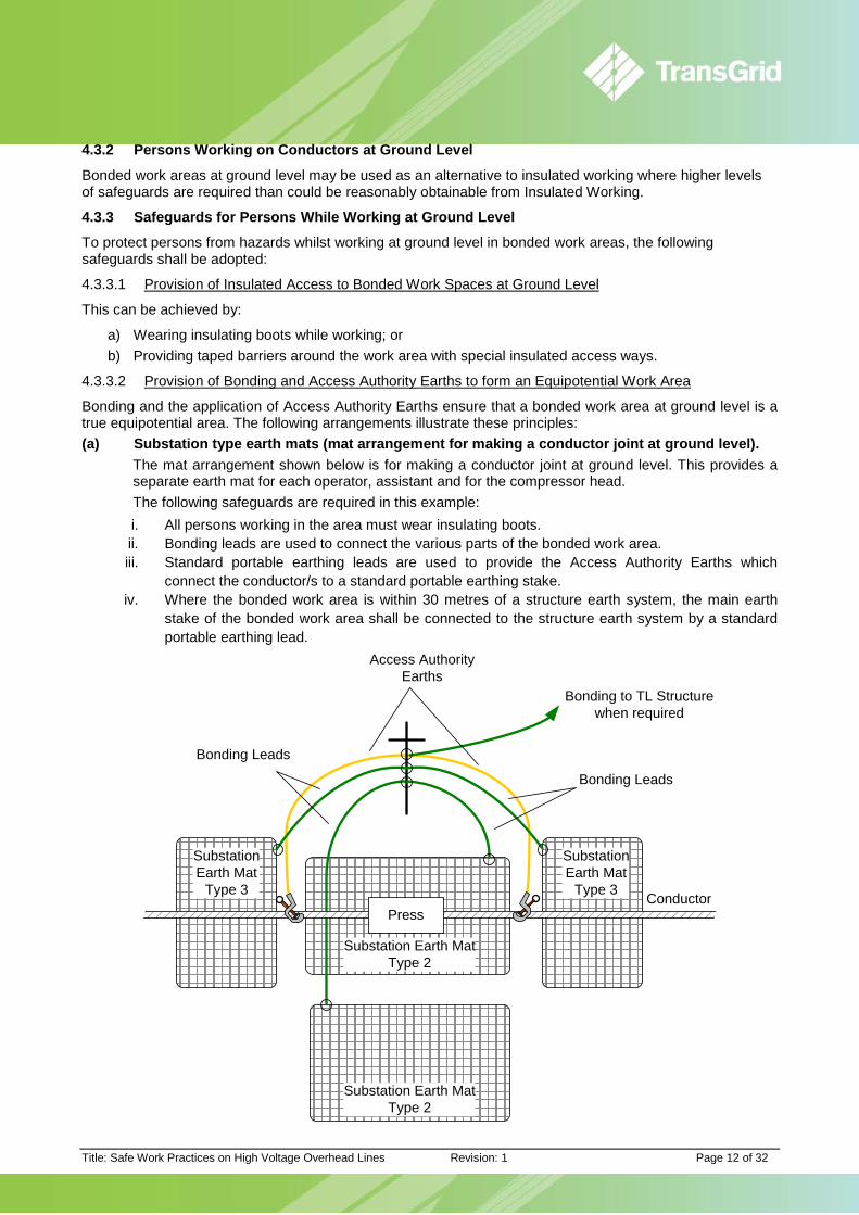
Bonding and the application of Access Authority Earths ensure that a bonded work area at ground level is a true equipotential area. The following arrangements illustrate these principles: (a) Substation type earth mats (mat arrangement for making a conductor joint at ground level).
The mat arrangement shown below is for making a conductor joint at ground level. This provides a separate earth mat for each operator, assistant and for the compressor head. The following safeguards are required in this example: i. All persons working in the area must wear insulating boots. ii. Bonding leads are used to connect the various parts of the bonded work area. iii. Standard portable earthing leads are used to provide the Access Authority Earths which
connect the conductor/s to a standard portable earthing stake. iv. Where the bonded work area is within 30 metres of a structure earth system, the main earth
stake of the bonded work area shall be connected to the structure earth system by a standard portable earthing lead.
PressConductor
Access AuthorityEarths
SubstationEarth Mat
Type 3
SubstationEarth Mat
Type 3
Substation Earth MatType 2
Substation Earth MatType 2
Bonding to TL Structure when required
Bonding Leads
Bonding Leads
Title: Safe Work Practices on High Voltage Overhead Lines Revision: 1 Page 13 of 32
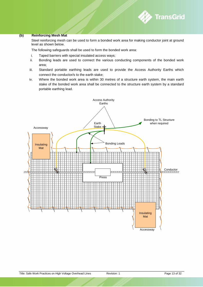
(b) Reinforcing Mesh Mat Steel reinforcing mesh can be used to form a bonded work area for making conductor joint at ground level as shown below.
The following safeguards shall be used to form the bonded work area: i. Taped barriers with special insulated access ways; ii. Bonding leads are used to connect the various conducting components of the bonded work
area; iii. Standard portable earthing leads are used to provide the Access Authority Earths which
connect the conductor/s to the earth stake; iv. Where the bonded work area is within 30 metres of a structure earth system, the main earth
stake of the bonded work area shall be connected to the structure earth system by a standard portable earthing lead.
InsulatingMat
InsulatingMat
Press
Conductor
Bonding to TL Structure when required
Access AuthorityEarths
Earth Stake
Bonding Leads
Accessway
Accessway
Title: Safe Work Practices on High Voltage Overhead Lines Revision: 1 Page 14 of 32
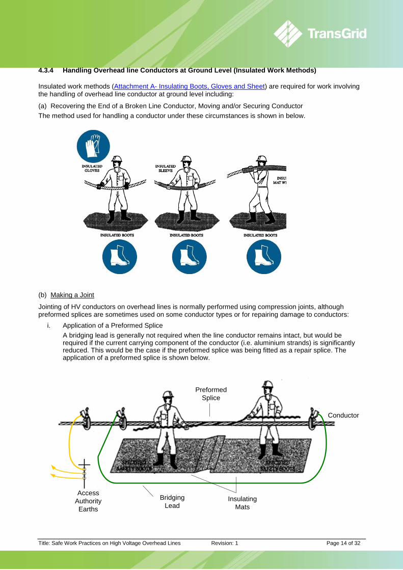
4.3.4 Handling Overhead line Conductors at Ground Level (Insulated Work Methods)
Insulated work methods (Attachment A- Insulating Boots, Gloves and Sheet) are required for work involving the handling of overhead line conductor at ground level including:
(a) Recovering the End of a Broken Line Conductor, Moving and/or Securing Conductor The method used for handling a conductor under these circumstances is shown in below.
(b) Making a Joint
Jointing of HV conductors on overhead lines is normally performed using compression joints, although preformed splices are sometimes used on some conductor types or for repairing damage to conductors:
i. Application of a Preformed Splice A bridging lead is generally not required when the line conductor remains intact, but would be required if the current carrying component of the conductor (i.e. aluminium strands) is significantly reduced. This would be the case if the preformed splice was being fitted as a repair splice. The application of a preformed splice is shown below.
Conductor
Access AuthorityEarths
Preformed Splice
Bridging Lead
Insulating Mats
Title: Safe Work Practices on High Voltage Overhead Lines Revision: 1 Page 15 of 32
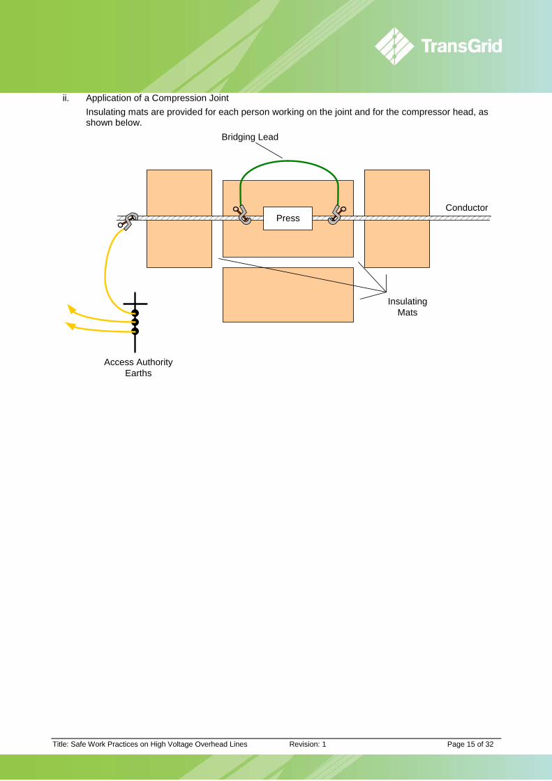
ii. Application of a Compression Joint Insulating mats are provided for each person working on the joint and for the compressor head, as shown below.
PressConductor
InsulatingMats
Bridging Lead
Access AuthorityEarths

Title: Safe Work Practices on High Voltage Overhead Lines Revision: 1 Page 16 of 32
4.4 Persons Working Aloft For persons working aloft it is essential that: (a) Access Authority Earths are to be applied as close as practicable to the point of work, in accordance
with the Power System Safety Rules; (b) A bonded work space is used for all work; and (c) All conducting lines and winch ropes are electrically connected to the bonded spaces.
4.4.1 Bonded Work Spaces Aloft
The bonded work space is the most effective safeguard against electrical hazards for staff working aloft on HV overhead lines. The bonded work space aloft is created by: (a) Application of Access Authority Earths at the point of work; (b) Bonding, using bridging leads, of other conducting parts or systems that are not directly joined within
the Bonded Work Space by the access authority earths.
4.4.2 Bonded Work Space –Steel Tower
Most overhead line steel tower structures are completely bonded around the top of the structure in the "space" of the HV conductors and overhead earthwire when Access Authority Earths are applied as shown below.
Access Authority Earths applied on tower
Title: Safe Work Practices on High Voltage Overhead Lines Revision: 1 Page 17 of 32
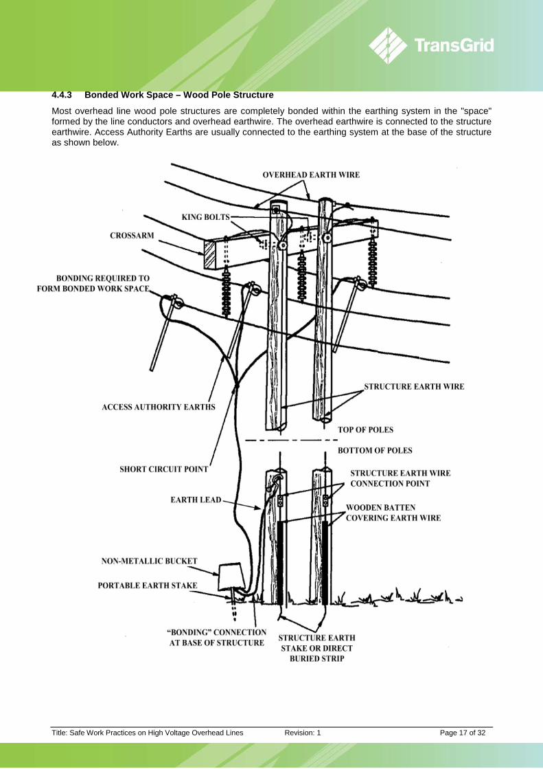
4.4.3 Bonded Work Space – Wood Pole Structure
Most overhead line wood pole structures are completely bonded within the earthing system in the "space" formed by the line conductors and overhead earthwire. The overhead earthwire is connected to the structure earthwire. Access Authority Earths are usually connected to the earthing system at the base of the structure as shown below.

Title: Safe Work Practices on High Voltage Overhead Lines Revision: 1 Page 18 of 32
4.4.4 Bonded Work Space – Elevated Work Platform
When using Elevated Work Platforms (EWPs) for maintenance work on transmission line structures and conductors, a bonded work space must be established.
The figure below illustrates an (EWP) being used for work on conductor spacers.
The figure shows a conductive platform, which is bonded to the conductor through the bonding lead attached to the boom or platform.
With non-conductive platforms, a conductive mat should be placed in the floor of the platform and bonded to the conductor using a bonding lead. In situations of high induced voltages, boots with conductive soles (or conductive leg-straps passing under the soles of the boots), will improve the effectiveness of the bonding.
Persons remaining at ground level and in the vicinity of the EWP vehicle must keep clear of the earth stake and the vehicle unless required to access the vehicle.
If required to access the vehicle precautions shall be taken to avoid high step and touch voltages as described in Section 4.3 Safeguards for Persons While Working at Ground Level.
The earth stake associated with the EWP shall be bonded to the tower (or pole earth) with a standard portable earthing lead in all cases except where:
a) The elevated work platform vehicle and earth stake are more than 30 metres from the nearest tower (or pole); and
b) The EWP platform is not being used for work on the tower (or pole).
Access Authority Earths applied on tower
Bonding Lead
Note: EWP earth must be bonded to structure earth except for work >30m from structure
Title: Safe Work Practices on High Voltage Overhead Lines Revision: 1 Page 19 of 32
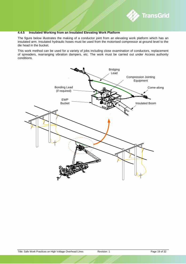
4.4.5 Insulated Working from an Insulated Elevating Work Platform
The figure below illustrates the making of a conductor joint from an elevating work platform which has an insulated arm. Insulated hydraulic hoses must be used from the motorised compressor at ground level to the die head in the bucket.
This work method can be used for a variety of jobs including close examination of conductors, replacement of spreaders, rearranging vibration dampers, etc. The work must be carried out under Access authority conditions.
Bonding Lead (if required)
EWP Bucket
Bridging Lead
Come-along
Insulated Boom
Compression Jointing Equipment

Title: Safe Work Practices on High Voltage Overhead Lines Revision: 1 Page 20 of 32
4.5 Making or Breaking Connections on High Voltage Overhead Lines Persons making or breaking conductors, connections, jumpers, or earthing connections must apply a bridging lead before making or breaking connections.
4.5.1 Application of a Bridging Lead
A Bridging Lead is a conductor which is used to maintain a current path when a conductor is to be broken or disconnected. The lead shall have a current rating which is at least equal to the fault rating of the Access Authority earths used. Details of the lead, clamps and its application are contained in Portable Earthing of High Voltage Conductors.
Two single phase earth leads may be used in lieu of the bridging lead, provided the two earthing leads are connected at the same earthing point.
If a connection in a line conductor or structure earthwire is to be broken and the bridging lead removed, then:
(a) The line conductor or structure earthwire is to be earthed prior to removing the bridge; and
(b) In the case where a structure earthwire is opened at the base of a structure a bridging lead around the break shall be used throughout the work, the end connected to the earth grid shall be insulated or covered by insulating material before the structure earth is handled.
4.6 Large Work Sites Large work sites are those where the particular work process is to be carried out over multiple spans of a HV overhead line, such as where several towers have collapsed or on line construction or rebuild projects.
At large work sites, where work is to be carried out at ground level on conductors or overhead earthwires, hazards may be present due to the existence of connections between the conductors or earthwires being worked on and remote substation earth mats. These hazards may be transferred to various points over the work site whenever sections of conductor or overhead earthwire are removed or replaced. The removal or replacement of conductors may also introduce hazards of induction from nearby live lines. Therefore working methods on large work sites are to be subject to an Engineer's Assessment.
The electrical hazards to persons can be reduced considerably by breaking connections (jumpers) in both the line conductors and the overhead earthwires on each side of the large work site. In addition, it may also be necessary to insert an insulator in the earthwire attachments at the point of breaking connections (jumpers).
4.7 Stringing an Overhead Line Parallel to an In-Service Line Persons working on the stringing of conductors or overhead earthwires on HV overhead lines which run parallel to an in-service HV line can be subject to significant hazards from induced voltages and currents.
4.7.1 Work Areas and Equipment
The stringing process may involve some of the following items of equipment:
a) Draw ropes (non conducting draw wires); b) conductors/earthwires; c) drums - for winding on conductors, earthwires, or draw wires; d) drum stands - which may be fitted with braking or rewinding mechanisms; e) winch - for pulling out conductor/earth wire/draw wires; f) tensioning machines - for tensioning conductor/earth wire during run-out; and g) jointing compressors - for joining conductor/earth wire.
2. Bridge in place
3. Clamp removed
1. Clamp to be removed
4. Bridge removed
Note: Dangerous voltage may exist

Title: Safe Work Practices on High Voltage Overhead Lines Revision: 1 Page 21 of 32
The equipment allocated for the work may be grouped at various locations, the purpose of which can vary with the work method used.
A commonly used arrangement involves a main work-site and a subsidiary work-site. These are described in detail in the following sections:
4.7.1.1 Main Work Site
A main work site could be as large as 100 metres x 30 metres, and include the following equipment:
a) draw rope/wire drums -mounted on stands;
b) conductor drum mounted on stands, with braking;
c) earth wire drums - mounted on stands, with braking;
d) conductor tensioning machines; e) conductor jointing machines -
trailer or truck mounted; f) space adjacent to the work site
for storage of conductor drums and overhead earth wire drums;
g) space adjacent to the work site for vehicles/cranes etc which are not directly involved in the work while the running-out of conductor or earth wire is in progress.
The diagram, at right, shows an example of a main work site. 4.7.1.2 Subsidiary Work Site(s)
A subsidiary work site is established over a small area for intermediate jointing, winching or other work associated with the draw wire or conductor.
The diagram at right shows an example of a subsidiary work site.
4.7.2 Standard Safeguards to be applied for Stringing Operations
Effective earthing of draw wires, earth wires and conductors is to be maintained throughout the duration of the run out. Earthing is to be as follows.
(a) Running out operation where a winching method is used: Two earths are to be applied, one close to the drum site, the other close to the winch site.
(b) Running out operation from a drum carried on a moving vehicle:
A single earth is to be applied close to the commencement point of the section.
This earthing should be carried out using specially

Title: Safe Work Practices on High Voltage Overhead Lines Revision: 1 Page 22 of 32
designed fittings such as rolling earths. When bundled conductor is being run out, each single conductor making up the bundle is to be individually earthed.
After being run out, each phase conductor and earth wire is to be earthed, using a standard portable earthing lead, at intervals of not more than 3 km by connecting the earths to either the structure steelwork or the structure earthing system.
In cases where overhead earth wires have been permanently bonded to the structure or the structure earthing system at an earthing location, earths will only be required on the phase conductors.
The location of all such earthing connections must be recorded so that a check can be made to ensure that they have been removed before the line is energised.
4.7.2.1 Additional Safeguards to be Applied for Stringing Operations in areas of Moderate Induction Exposure
Additional safeguards required are listed below:
a) When a crew of line workers is carrying out work at a structure and there is a possibility that their tools or other items of equipment may make contact with conductors, such conductors are to be connected to the structure steelwork or the structure earth system by means of bonding leads, for the duration of the work. The leads must not be broken during the course of the work. Such connections shall be recorded;
b) While line work, (i.e. running out of conductors and earth wires, stringing and all subsequent work) is being carried out, mobile equipment such as cranes operating at any structure is to be connected to the structure earthing system by means of a standard portable earthing lead.
c) All persons associated with running out, stringing and other line work at ground level, are to work under insulated working conditions and are to be briefed on the hazards associated with the work.
d) Draw wires shall be insulated from pulling vehicles. e) Jumpers between affected sections of the line and jumpers linking these sections to the adjoining
sections shall not be installed until all other overhead line work has been completed.
4.7.2.2 Further Additional Safeguards which may be required for Stringing Operations
The further additional safeguards are detailed below:
a) Main work sites are to be established as a bonded work area. All material and equipment associated with the running out of draw wires, earth wires and conductors are to be bonded to it via a central stake as shown below. Entrance to or exit from the bonded work area is to be via insulating mats, with a taped barrier defining the edges of the bonded work area.
b) Subsidiary work sites are to be established as bonded work areas.
c) No conductor, earth wire or metallic draw wire shall be permitted to come within 2.5 metres of ground level at any location other than at a main
Title: Safe Work Practices on High Voltage Overhead Lines Revision: 1 Page 23 of 32
or subsidiary work site. All connections used in the earthing arrangements under (a) and (b) above are to be made using standard portable earthing leads. For details on bonded work areas at ground level refer to Section 4.3.
The running out of metallic draw wires or conductors from a drum carried on a moving vehicle is not acceptable under these circumstances.
4.8 Stringing Conductor on Landing Span to HV Substations Staff working on the stringing of conductors and overhead earthwires up to the landing span in the substation, i.e. between a HV overhead line and a structure in a HV Substation can be subject to significant hazards from the rise in voltage of the substation earth grid under system fault conditions or system switching activities.
Earth grid voltage rise can be transferred to persons outside the switchyard and may occur at any time.
Similarly, staff working within the switchyard can become connected to a remote earthing system which can lead to a hazardous voltage during a rise in the voltage of the substation earth grid.
4.8.1 Standard Safeguards
a) It is best practice for all work on the HV overhead lines to be completed before the landing span is erected. If this cannot be done it may be necessary to temporarily install a single disc insulator in the overhead earth wire at the first structure and to leave the conductor jumpers completely disconnected or tied back onto the landing spans. These precautions will limit the extent of transfer voltage effects.
a) The connection and disconnection of jumpers is to be carried out using the standard bridging process.
b) All terminations to conductor or overhead earth wire made at ground level in the general vicinity of the landing spans are to be carried out under bonded work area conditions.
c) The person in charge of the work is to ensure that the Controller is advised prior to the commencement and on completion of stringing operations involving landing spans.

Title: Safe Work Practices on High Voltage Overhead Lines Revision: 1 Page 24 of 32
4.8.2 Outline of Procedure for Stringing landing Spans
Access authority procedures must be implemented prior commencement of the work.
Procedures to be followed for stringing landing spans are:
a) A bonded work area shall be established around the first structure and connected to the structure earth (Figure below). Insulating boots are to be worn by all persons working at ground level during the course of the work. (This will be a safeguard from possible step and touch voltage which could arise when the structure is connected to the switchyard earth grid).
b) The first structure shall be bonded to the switchyard earth mat in the following way: i. using a standard portable earthing lead, the lead shall be connected to the first structure outside
the switchyard;

Title: Safe Work Practices on High Voltage Overhead Lines Revision: 1 Page 25 of 32
and then:
ii. under insulated working conditions, the lead shall be run out towards and into the switchyard; iii. under insulated working conditions, persons shall connect the lead to the switchyard earth grid
as shown in the following diagram.
(c) Winches, brakes and other equipment associated with the stringing operation are to be connected to
the switchyard earth mat directly or via the earthing of the first structure. The connection shall be carried out using the procedure outlined in (b) above.
(d) Stringing of each conductor or overhead earthwire shall be carried out in such a way that neither the conductor nor the overhead earthwire makes contact with the switchyard earth grid whilst the conductor is being handled by persons outside the switchyard.
Either of the following options may be used:
Title: Safe Work Practices on High Voltage Overhead Lines Revision: 1 Page 26 of 32
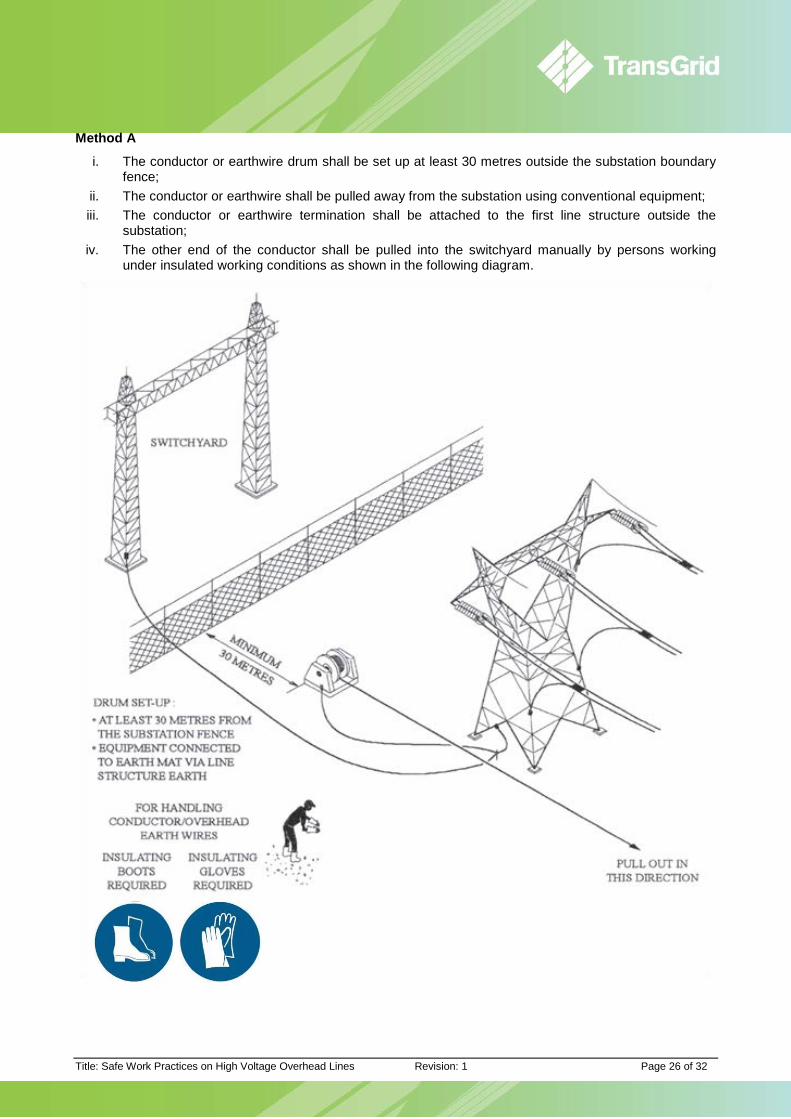
Method A
i. The conductor or earthwire drum shall be set up at least 30 metres outside the substation boundary fence;
ii. The conductor or earthwire shall be pulled away from the substation using conventional equipment; iii. The conductor or earthwire termination shall be attached to the first line structure outside the
substation; iv. The other end of the conductor shall be pulled into the switchyard manually by persons working
under insulated working conditions as shown in the following diagram.
Title: Safe Work Practices on High Voltage Overhead Lines Revision: 1 Page 27 of 32
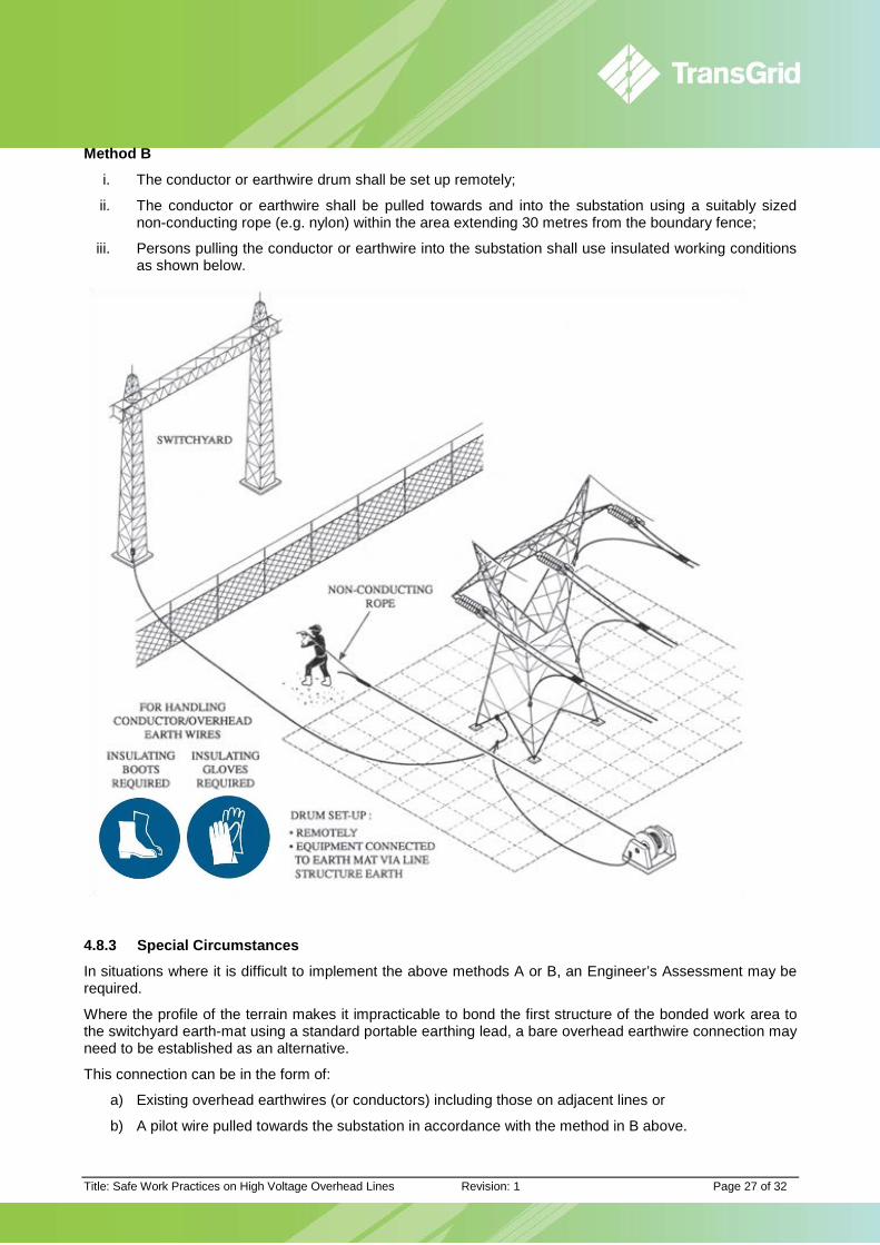
Method B
i. The conductor or earthwire drum shall be set up remotely;
ii. The conductor or earthwire shall be pulled towards and into the substation using a suitably sized non-conducting rope (e.g. nylon) within the area extending 30 metres from the boundary fence;
iii. Persons pulling the conductor or earthwire into the substation shall use insulated working conditions as shown below.
4.8.3 Special Circumstances
In situations where it is difficult to implement the above methods A or B, an Engineer’s Assessment may be required.
Where the profile of the terrain makes it impracticable to bond the first structure of the bonded work area to the switchyard earth-mat using a standard portable earthing lead, a bare overhead earthwire connection may need to be established as an alternative.
This connection can be in the form of:
a) Existing overhead earthwires (or conductors) including those on adjacent lines or
b) A pilot wire pulled towards the substation in accordance with the method in B above.
Title: Safe Work Practices on High Voltage Overhead Lines Revision: 1 Page 28 of 32
4.9 Testing of HV Overhead Lines - Safeguards for Use of Test Instruments Persons using test instruments on high voltage overhead lines may be subjected to high level electrical hazards during the period in which it is necessary to remove safety earths to obtain effective measurements.
The principal hazards are
• induced voltages: where the line under test is closely coupled with other in-service HV lines, resulting in high levels of induced voltages;
• earth mat voltage rise: from system faults or switching surges, which could appear at the testing site through the overhead line conductors or overhead earth wire;
• lightning surges: direct strike or induced, could be directly conducted into the test instruments; and • voltage gradients in the vicinity of the test site could be significant if the line becomes alive while the
safety earths are removed.
The following procedures will provide safeguards for persons conducting tests on HV overhead lines which are subject to routine induction and transfer effects.
Such tests could involve the use of the following devices:
• F.L.O.S. (Fault Locator on System); • Meggers; • Battery with ammeters.
Proposals to carry-out complicated tests or tests in potentially hazardous circumstances, should be discussed with the person responsible for the tests.
To safeguard persons during the tests the following procedures shall be applied in addition to the requirements of the Power System Safety Rules:
a) An Engineer’s Assessment shall be made of the electrical hazards which may be encountered and the working methods to be applied.
b) Where the line to be tested is:
• On a double circuit structure and the other circuit is ‘alive’, or
• Closely parallelled with another in-service line
The proposed working methods must be discussed with a representative of the testing contractor to check the adequacy of the proposed working methods.
c) All testing work shall be under insulated working conditions, involving the use of:
• An insulating mat; • Insulating boots (to safeguard persons while not on mat) d) Electrical supplies for the instruments being used in the tests are to be confined to the Insulated
Work Area.
For example, power for F.L.O.S. tests should come from a battery and inverter -both standing on the insulating mat.
Where it is not possible to carry out tests without external 240V supply an isolating transformer insulated to withstand 15 kV between windings shall be used.
e) A spark gap capable of handling the electrical hazards which may arise shall be provided across the input to the instrument, between the line conductors under test and the earth.
f) Test leads shall not be connected to or disconnected from overhead line conductors unless safety earths are in place at the work site.
g) The conductor under test shall be unearthed for the minimum time necessary to carry out the test.
h) Test leads shall be located at the side of the instrument remote from the person taking the reading.
i) Persons are to be warned immediately prior to removal of Access Authority earth(s) and shall be directed to keep clear of the test leads while they are connected to the unearthed conductor .

Title: Safe Work Practices on High Voltage Overhead Lines Revision: 1 Page 29 of 32
j) Persons carrying out testing must make contact with only one part of the test instrument at a time during the currency of the reading process.
The following figure illustrates a typical layout for the requirements to test HV overhead lines.
ACCESS AUTHORITYEARTHS
5. Amendments to Previous Issue Revision 0:
• Document replaced “Safe Work Practices on High Voltage Overhead Lines - GD SA G2 013”
• Removed basis of hazard theory
• Added Hazardous Situations table
• Added hyperlinks
Revision 1:
• Section 4.4.4 wording revised. Refer INS 1550
• Section 4.6 wording revised
• Document links revised.

Title: Safe Work Practices on High Voltage Overhead Lines Revision: 1 Page 30 of 32
6. Attachment A- Insulating Boots, Gloves and Sheet A1.1 Safety Boots for Line worker
For work on overhead lines at ground level special safety boots are provided to safeguard line workers from electrical hazards. These boots have the following characteristics:
a) Moulded rubber sole;
b) Leather uppers with “smoothed-out” exterior –suede leather is not acceptable;
c) Leather tongue sewn to deter ingress of moisture.
For work under wet conditions, ‘Wellington’ type safety boots are provided which have moulded rubber soles and a safety type steel toe cap, refer figure right.
A1.2 Insulating Boots
Insulating boots are special boots of the “Wellington” or “Half Wellington” type made from plastic or non-conducting rubber with proven levels of insulation. These boots must have been tested to withstand 15 kV AC for 1 minute within the previous 12 months.
Insulating boots are to be used for working in special situations where an Engineer’s Assessment has determined the work site as a hazardous location.
Prior to use, these boots are to be inspected to ensure that they are clean, free from cuts, punctures or metallic pieces lodged in the tread or sides. When not in use insulating boots must be carefully stored and on completion of work, must be cleaned and inspected before returning to storage.
A1.3 Conducting Boots for Live Line Work
Conducting boots used for Live Line Work are NOT suitable for overhead line work at ground level.
A1.4 Insulating Sheet
Insulating sheets are marketed as neoprene sheet and are also known as neoprene rubber or polychloroprene. Minimum sheet thickness is to be 5mm. Insulating sheet may be used singularly or in multiple units and must:
a) be laid on ground which is free of surface water;
b) provide for a minimum overlap of 100 mm where sheets are laid together;
c) be laid on a wooden platform (or planks) in situations where:
• the ground surface prevents direct laying; or
• the sheeting may be damaged during the course of work.
Insulating sheet must be inspected prior to use for general condition and for cuts and punctures and shall have been tested to 15 kV AC within the previous 12 months. Sheeting having significant damage must not be used for insulating purposes. When not in use, sheeting must be carefully cleaned and stored.
A1.5 Insulating Material for Covering Conductors
Where a line conductor is lowered, it may be necessary to provide insulation around the conductor to protect persons working at ground level from possible electrical hazards. (refer Section 4.3.4). Insulating sheet may be used for this purpose.
As an alternative, a spiral split neoprene or non-conductive rubber hose, tested to withstand 15 kV AC for 1 minute within the previous 12 months, may be used for the insulation of lowered conductors. The use of these insulated work methods must only be carried out under the following conditions:
• where a commissioned line is isolated and earthed and Access Authority Earths are applied under Access authority conditions.
• where a line being constructed is isolated and earthed according to the specified requirements of the construction.

Title: Safe Work Practices on High Voltage Overhead Lines Revision: 1 Page 31 of 32
A1.6 Gloves for Insulated Working
Insulating gloves will be used in situations where touch voltage hazards could develop and in situations where the line conductor is to be handled at ground level and voltage transfer hazards could develop.
Generally the need to wear insulating gloves will be determined by the risk assessment process and/or the Engineer’s Assessment. In many such instances insulating gloves will be worn in conjunction with insulating boots.
To protect insulating gloves from mechanical damage, an outer glove made from a suitable durable material must also be worn.
Insulating gloves are made from neoprene or rubber. A glove pair must have been tested to withstand 15 kV AC for one minute within the previous 12 months.
Australian Standard 2225 -1994 stipulates that insulating gloves are to be inspected immediately prior to use to ensure that they are clean and free from abrasions and cuts and then must be air (roll) tested for punctures. A method is outlined in below. Should there be any doubt concerning the condition of insulating gloves, they are to be replaced. The gloves must be cleaned, inspected and air tested before storing.
Title: Safe Work Practices on High Voltage Overhead Lines Revision: 1 Page 32 of 32
7. Attachment B- Using an approved insulating ladder for access