safe-life and damage-tolerant design … · damage tolerance is a safety requirement and equates to...
TRANSCRIPT

SAFE-LIFE AND DAMAGE-TOLERANT DESIGN APPROACHES FOR HELICOPTER STRUCTURES
Harold K. Reddick, Jr. Applied Technology Laboratory
US Army Research and Technolosy Laboratories (A~~RFlDCO!!¶) Ft Eustis, Virginia
https://ntrs.nasa.gov/search.jsp?R=19830025690 2018-07-10T08:46:09+00:00Z

INTRODUCTION
The safe-life and damage-tolerant design approaches presented herein apply to both metallic and fibrous composite helicopter structures. However, to maintain the theme of this workshop, this presentation will emphasize the application of these design approaches to fibrous compos- ite structures.
In the current generation of Army helicopters, such as the UH-60 Black Hawk shown in Figure 1, composite materials make up as high as 17 percent of the airframe and rotor weight. With the advent of major helicopter composite structures R&D projects, such as the Advanced Composite Airframe Program (ACAP), and Manufacturing Methods and Tech- nology (MM&T) projects, such as UH-60 Low Cost Composite Blade Program, it is estimated that within a few years composite materials could be applied to as much as 80% of the airframe and rotor weight of a heli- copter in a production program. Along with this application is the essential requirement that sound, definitive design criteria be developed in order that the composite structures possess high fatigue lives for economy of ownership and good damage tolerance for flight safety.
Safe-life and damage-tolerant criteria are applied to all helicopter flight critical components, which are generally categorized as follows:
- Dynamic components - main and tail rotor system, which includes blades, hub and rotating controls, and drive train which includes trans- mission, and main and interconnecting rotor shafts.
- Airframe - fuselage, aerodynamic surfaces and landing gear.
Figure 1

TYPICAL STRESS SP%CTRA FO'R A HELICOPTER BLAbF ROOT END, AND TRANSPORT' AIRPLANE' ROOT END
The dynamic components previously described tend to be fatigue critical. Although fatigue problems have been known to occur within the helicopter airframe, it for the most part is designed by strength and minimum gage.
Figure 2 shows a typical comparison of the stress history for a trans- port helicopter blade root end and that for a.typical commercial trans- port wing root. The helicopter dynamic components tend to be loaded at frequencies that are a multiple of rotor speed - typically 2 to 20 Hz. This loading rate represents 7 million to 70 million cycles per 1000 operating hours. Thus these components experience a much higher fre- quency of cyclic loading but with a narrower spread of the loading than the fixed wing aircraft component.
HELKOPTER BLADE ROOT END
+ TYPICAL FPEQUEHCY OF CYCLIC LOADING 7000 to 70,OOD CYCLES/HOUR
0 I -
ul TIME - IA
+ GROUND AIR GROUND TRANSPORT AIRPLANE WING ROOT
TYPKAL FREQUEIKY Of CYCLK LOADING 0 '- 100 TO 1000 CYCl;S/HOUR
Figure 2
131

SAFE. LI:FE .P:HI.LOS#PH~Y.
The safe-life design approach is stated in Figure 3. It applies to statistically predictable failures which are those occurring from the random combination of fatigue strength and applied fatigue loads.
ALL FATIGUE CRITICAL COMPONENTS OF THE HELICOPTER ARE DESIGNED TO A SPECIFIC SERVICE LIFE, IN OPERATIONAL HOURS, AND ARE REMOVED FROM SERVICE AT OR BEFORE THIS ELAPSED TWE SO THAT THE PROBABILITY OF A FATIGUE FAILURE IS REMOTE
Figure 3
132

SAFE-LIFE METHODOLOGY
The methodology for the fatigue design of primary structural com- ponents is schematically outlined in Figure 4. The three basic elements of safe-life design include:
- Working Fatigue S-N Curve- developed based upon coupon tests to determine curve shapes, full-scale specimen tests to provide data points for constructing a mean curve, and then a statistical reduction of the mean curve to a "working" curve upon which the damage.calculations are based. A minimum of six,full-scale test specimens are generally required to establish the mean curve. The statistical reduction is made on the stress (and not cycles) for it is the high cycles region of the S-N curve at which fatigue loading occurs.
- Design Loading Spectra - developed from the mission profile which is a prediction of how the aircraft shall be used, and the flight loads which are developed for the various maneuvers and flight condi- tions of the helicopter's mission profile. Obviously in the development of a new helicopter s,ystem, these loads must initially be either pre- dicted or empirically derived from measured loads on similar helicopters.
- Cumulative Damage Theory - the combination of loads and fatigue strength by means of a cumulative damage theory results in the component fatigue life.
The safe-life methodology outlined herein typifies that used by most US and European helicopter manufacturers (references 1 through 3) although specific approaches for analysis of the loads and the material fatigue data vary with the manufacturers.
For the UH-60 Black Hawk and the YAH-64 Apache, the Army's more recent helicopter development programs, the minimum required fatigue life for all dynamic components has been 5,000 and 4,500 flight hours, respectively. Many of the components on these aircraft have exceeded their minimum fatigue life requirement.
Figure 4
133

-FAILURE :RATE VS FId.GHT HOURS
The safe-life design approach, when properly executed, places statistically predictable failures at an extremely remote probability of occurrence. This approach does, however, assume the structure to ' be flaw free. Over the years operational experience has shown (refer- ences 4 through 6) that the safe-life approach by itself is not adequate because of unpredictable failures resulting from such sources as manu- facturing defects and service-induced damage (see Figure 5). Further- more, review of this operational experience has shown these unpredictable failures to far outnumber the predictable ones.
RETIREMENT
E LIFE
2 Unexpected Causes
E (Defects, Damage, etc.)
7 Statistically
Figure 5
134

DAMAGE SOURCES
The statistically nonpredictable failures discussed in the previous figure result from one of three categories of damage - initial, as originating from material defects or manufacturing-induced anomalies, service-induced or ballistic. Examples for each of the damages are presented in Figure 6. Ballistic damage is certainly an in-service occurrence; however, because of the extreme nature of this damage and its associated short residual life requirement (30 minutes to roughly 5 hours), is generally addressed separately from the other damage types, and shall not be discussed herein.
. DESIGN ERRORS
. MATERIAL-AND MANUFACTURING-INDUCED DEFECTS - IMPROPER LAYUP
- INCORRECT/INCOMPLETE CURING
- MACHINING ERRORS
- HANDLING/ASSEMBLING AREAS
. SERVICE INDUCED DAMAGE - FOREIGN OBJECT DAMAGE [FllDI
- MAINTENANCE ERRORS
- GROUNO HANDLING
. BALLISTIC DAMAGE - SMALL ARMS PROJECTILES 17.62mm & 12.7mml - HIGH EXPLOSIVE INCINOIARY 123mm HEI-TI
Figure 6
135

EARLY DAMAGE TOLERANCE REQUIREMENTS
Although damage tolerance as we know it today is a relatively new technology, its importance was recognized as long as four centuries ago. Near the end of the fifteenth century, technical notes were written on what must have been one of the first requirements for damage-tolerant design. They were in the notebook of Leonardo da Vinci in which he discussed the physics of flight and the design of "flying machines," and are shown in Figure 7 (reference 7).
In the early 60's a fail-safe design philosophy began to evolve within the rotory wing industry and has been used in numerous applica- tions for both metallic and fibrous composite structures (references 8 through 10). The safeguard in the fail-safe approach is that damage, induced or fatigue, will be detected by inspection procedures before it grows to such an extent that the residual strength of the structure is reduced below a safe level.
In the early 70's a third design philosophy - damage tolerance - began to evolve. It is similar'to the fail-safe approach but further considers the growth of damage resulting during manufacture or service usage. Therefore, fundamental to the damage-tolerant approach is an understanding of structural performance in the presence of defects or damage.
“IN CONSTRUCTING WINGS ONE SHOULD MAKE ONE CORD TO BEAR THE
STRAIN AN0 A LOOSER ONE IN THE SAME POSITION SO THAT IF ONi
BREAKS UNOER STRAIN THE OTHER IS IN POSITION TO SERVE THE SAME
FUNCTION:
fROM LEOIIARDO DA VIMCI’S KOTEBOOK
OK DESIGN Of “ILVIWG MACHIRES”
ISlEI CENIURV
Figure 7
136
DAMAGE TOLERANCE PHILOSOPHY
Damage tolerance is a safety requirement and equates to the fail- safe design approach employed for flight critical components by the rotary wing industry since the early 60's. Damage tolerance is the ability of the structure to resist failure due to the presence of defects, cracks, or other damage for a time period sufficient to enable their detection.
The essential elements of damage tolerance are presented in Figure 8. In designing to this philosophy, the criteria must address both the static residual strength and damage propagation for the structure under consideration.
The fail-safe and damage tolerance design philosophies each have the common objective of providing structural integrity at a reasonable level of assurance for all safety-of-flight structures, that is struc- ture whose failure could cause direct loss of the aircraft. Reference 5 points out an important distinction between fail safety and damage tolerance. Fail safety as it was defined prior to the evolution of damage tolerance is based upon the premise that one cannot be certain that cracks (or damage) will not initiate at some time during the air- craft life and these cracks must be detected before the strength drops below a certain level. Damage tolerance, on the other hand, assumes the existence of initial flaws in the structure and the structure is designed to retain adequate residual strength until damage is detected and corrective actions taken.
Although the damage-tolerant approach has begun to see a more wide- spread usage within the Army, there is still considerable work to be accomplished in developing specific requirements and procedures for this design approach.
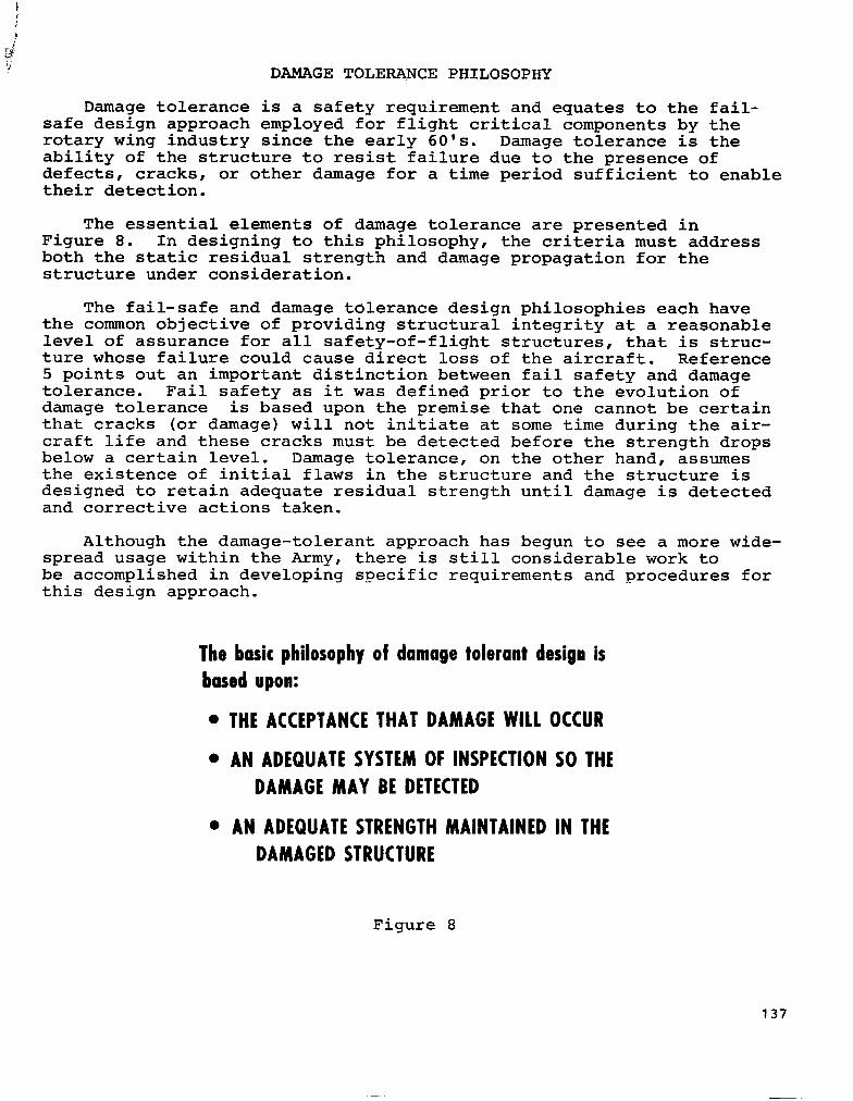
The basic philosophy of damage tolerant design is based upon:
l THE ACCEPTANCE THAT DAMAGE WILL OCCUR
l AN ADEQUATE SYSTEM OF INSPECTION SO THE DAMAGE MAY BE DETECTED
l AN ADEQUATE STRENGTH MAINTAINED IN THE DAMAGED STRUCTURE
Figure 8
137

RESIDUAL STRENGTH AND DAMAGE GROWTH
The damage-tolerant requirement, which is illustrated schematically in Figure 9, addresses both the residual strength and the damage propagation for the structure under consideration.
The residual strength is the amount of static strength available at any time during the service exposure with damage present. Safety is ensured by designing to requirements wherein damage is never allowed to grow and reduce the residual static strength of the structure below a specified value, such as that corresponding to the maximum load to be experienced in service.
The damage growth curve presents damage size as a function of time. The period of time required for damage to grow from a minimum detect- able size, such as by in-service inspection, to a critical size is the detection period. The critical size generally corresponds to the maxi- mum service load residual strength, although. for composites this value could be dictated by stiffness loss to a critical value.
Figure 9
138

DAMAGE TOLERANCE APPROACHES
Damage tolerance may be achieved in one of two different methods as shown in Figure 10. In fail-safe structures, damage tolerance (and their safety) is assured by the allowance of partial structural failure, the ability to detect this failure prior to total loss of the structure, the ability to operate safely with the partial failure prior to ins'pec- tion and the maintenance of specified- static strength throughout the period. Fail-safe structures are usually comprised of multiple elements or load paths such that damage can be safely contained by failing a load path or by arresting a rapidly running crack. In safe crack growth structures, damage tolerance is achieved by sizing the structure, using fracture mechanics or empirical data, such that initial damage will grow at a stable, slow rate and not achieve a size large enough to fail the structure prior to detection. A special case within this category is nonpropagating-defect structures wherein the structure is designed to sufficiently low stress levels for virtually no propagation of the largest defect that would not be detected during a production inspection or that could be incurred in service.
SAFETY OF FLIGHT STRUCTURES
Figure 10
139

SAFE-LIFE AND DAMAGE TOLERANCE REQUIREnENTS FOR ARMY HELICOPTERC
The structural design specification for helicopter MIL-S-8698 imposes requirements for safe-life fatigue design of flight critical structures but not for fail-safe or damage tolerance design (Figure 11). In the more recent major helicopter system procurements, the Army has required fail safety or damage tolerance for the helicopter primary structure. These requirements have been stated in general terms as follows:
"The primary structure shall incorporate materials, stress levels, and structural configurations that will minimize the probability of loss of the aircraft due to damage of a single structural element (including control system or dynamic components), or due to propagation of unde- tected flaws, cracks, or other damage. Slow crack growth, crack arrestment, alternate load paths and systems, and other available design principles shall be used to achieve this capability.---"
Because of the general nature of these requirements, they were successfully applied to both metallic and fibrous composite structures (reference 11). It has been left up to the helicopter manufacturer to define the specifics such as damage or flaw sizes, inspection intervals, etc., subject, of course, to Government approval.
l ML-S-8698, STRUCTURAL DESIGN REQUIREMENTS, HELICOPTERS
- SAFE LIFE DESIGN REQUIREMENTS
- NO FAN SAFE/DAMAGE TOLERANCE DESIGN REQUIREMENTS
' SYSTEM DEVELOPMENT SPECIFICATIONS (UH-60, YAH-641
- FAIL SAFE/DAMAGE TOLERANCE DESIGN REQTS
- REQUIREMENTS ARE GENERAL
- TAILORED TO METALLIC STRUCTURES
Figure 11
140
COMPOSITE llAIN ROTOR BLADES
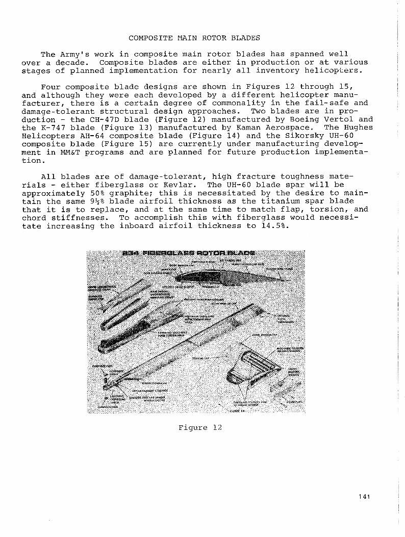
The Army's work in composite main rotor blades has spanned well over a decade. Composite blades are either in production or at various stages of planned implementation for nearly all inventory helicopters.
Four composite blade designs are shown in Figures 12 through 15, and although they were each developed by a different helicopter manu- facturer, there is a certain degree of commonality in the fail-safe and damage-tolerant structural design approaches. Two blades are in pro- duction - the CH-47D blade (Figure 12) manufactured by Boeing Vertol and the K-747 blade (Figure 13) manufactured by Kaman Aerospace. The Hughes Helicopters AH-64 composite blade (Figure 14) and the Sikorsky UH-60 composite blade (Figure 15) are currently under manufacturing develop- ment in MM&T programs and are planned for future production implementa- tion.
All blades are of damage-tolerant, high fracture toughness mate- rials - either fiberglass or Kevlar. The UH-60 blade spar will be approximately 50% graphite; this is necessitated by the desire to main- tain the same 9$% blade airfoil thickness as the titanium spar blade that it is to replace, and at the same time to match flap, torsion, and chord stiffnesses. To accomplish this with fiberglass would necessi- tate increasing the inboard airfoil thickness to 14.5%.
Figure 12

K-747 COMPOSITE BLADE
sir sir 48.00 bb.0
SiA sir 111.40 124.40 lb4.00
l7ACH~flllDtlAllFULlSfAN S GLASS WOUND AROUND ALUMIIIUM1llll11G
fllA,lilll WOUllDItVLAt/t~OXV TlAlllllGtDGl Nflltl OIlGIll
Figure 13
YAH-64 COMPOSITE MAIN ROTOR BLADE
IllDt ROD1 tllD
ROfDt DlANlll = 45 1551 ILAM CIDID = 11 IllClIS IWISI i -I DICIIIS :LADl AllfOIl = W.Ol/MAtA b4AOOb BlA~I WIlG11 = I55 PDYllD5
Figure 14
142

COMPOSITE MAIN ROTOR BLADES (CONTINUED)
All blades have a redundant load path root end except for the CH-47D blade; its single lug root end configuration was dictated by hub interface requirements. Hence fail safety in the root end has generally been achieved through redundancy.
For the constant airfoil section, damage tolerance is achieved with the material selection and relatively low design operating strain levels, typically 1500 pin./in. to'.1860 uin./in.
Two of the blade concepts - the K-747 and AH-64 - also contain structural redundancy of the spar in the airfoil region through a multi-tubular (or cell) concept; this is to a large degree for ballistic tolerance.
In general, the damage tolerance of these blades was developed and demonstrated through subcomponent and full-scale testing. Analysis was generally by classical techniques, with fail safety or damage tolerance assessed by assuming loss of a certain portion of the structure.
WI-60 COMPOSITE MAIN ROTOR BLADE
lOlOt DlAltltl = 53'1"
BLADI CUOlB = 21"
UAW WtlCHl = 211 LBS
UAIUIAClUIIIC PROCESS: WIT FllAU111
WIIIDl1C/C0CU~IIS
Figure 15
143

COMPOSITE ROTOR BLADE DAMAGE TOLERAKE DEMONSTRATED BY HLH ROOT END TEST
Some of t h e e a r l y R&D emphasis on composite b lades c e n t e r e d on t h e r o o t end, f o r t h e succes s of composite a p p l i c a t i o n s t o t h e r o t o r b l a d e hinged t o a l a r g e degree on t h e development of a r o o t end t h a t was s t r u c t u r a l l y e f f i c i e n t , f a i l s a f e , and a t t h e same t i m e p roduc ib le . Resu l t s from damage t o l e r a n c e t e s t i n g on t h e r o o t end of t h e HLH b l ade which was f i b e r g l a s s c o n s t r u c t i o n and weighed 780 l b s a r e summarized i n F igu re 16. A f t e r t e s t i n g t h i s specimen f o r 490 hours t o demonstra te s a f e l i f e , t h e specimen w a s damaged t o vary ing degrees , from s e v e r i n g one of t h e f o u r r o o t end l u g s t o removing a 6" x 12" s e c t i o n , and aga in t e s t e d a s shown i n t h e f i g u r e t o demonstra te i t s f a i l - s a f e p r o p e r t i e s . A t t h e c u t o u t s e c t i o n t h e a x i a l , f l a p , and chord s t i f f n e s s w e r e reduced by approximately 50 pe rcen t , and t o r s i o n w a s reduced by 85 p e r c e n t .
. UNDAMAGED AFTER
240 HOURSAT 1W%OF DESIGN LOADS 250 HOURSAT 3 W O F DESIGN LOADS
SUCCESSFULLY WITHST.000 100%OF DESIGN LOADS
40 HOURS WITH LUG CUT 130 HOURS WITH LUG CUT AND FORWARD UPPER STRAPS SLOTTED (118 IN. SPANWISE BY 6 IN. CHORDWISE) AND THEN
SUSTAINED LIMIT LOAD WITH NO DAMAGE PROPAGATION 30 HOURSWITH LUG CUT AND FORWARD UPPER AND LOWER STRAPSCUT 112 IN. SPANWISE BY 6 IN CHORDWISE1
Figure 16

COMPOSITE ROTOR BLADE DAMAGE TOLERANCE DEMONSTRATED BY UTTAS ROOT END TEST
Investigations have shown that initial deterioration of composites under repeated loading is manifested in a gradual loss of stiffness which is attributable initially to failure or breakdown within the resin. This factor, combined with another important feature that this loss in stiffness can occur, depending upon the stress level, many thousand cycles before static failure, yields the possiblity of inherent damage tolerance for many composite structures.
This detection method of stiffness loss has been demonstrated in full-scale fatigue testing of fiberglass rotor blades. Reference 8 reports that during fail-safe testing of the Boeing Vertol UTTAS rotor blade root end, which was fiberglass/epoxy construction, there was a noticeable decrease in torsional stiffness after approximately 2 x 1~~ cycles at elevated test loads. This testing is summarized in Figure 17. Although the blade still retained its full structural integrity, the change in stiffness was deemed a failure. The loads were dropped to high- speed level-flight values and the equivalent of 30 flight hours was run, with no further measured degradation. Test loads were then increased to the original high level and testing continued until blade deflec- tions exceeded machine capability. Even here there was no structural failure. Dynamic analyses, based upon reduc5d stiffness values, showed that the vibrational levels would have risen to a level noticeable to the pilot, but would still have been within a safe operating range. Additionally, regions of surface delamination became visible along with the stiffness loss. A key issue that must he addressed with this detec- tion procedure is tying the indication, such as increased vibration level, to the correct source.
1.89 LOAD (277% DESIGN TOROUE) TORSION .
3.0 1 I' RATIO: ONE MILLION CYCLESAT BEFLECTION TO 100% DESIGN LOAD INITIAL DEFLECTION '"
1.0
I I I I 0 1.0 2.0 3.0 4.0 5.0
CYCLES X lo-'
Figure 17

UH-6.0 COMPOSITE TAIL ROTOR SPAR
The UH-60 composite tail rotor spar provides a good example of the need for damage tolerance criteria for composites. This component is in:production on the UH-60. It is graphite/epoxy and is highly complex in configuration, being made up of more than 300 individual detailed plies in order to satisfy strength and stiffness distribution require- ments. Because of this complexity and the manufacturing process used, the rejection rate of this component during early production was quite high. Because the effect of manufacturing defects (See Figure 18) had not been quantified for this component, the acceptance criteria was stringent.
Three steps were taken to reduce this unacceptably high rejection rate:
1. Alternate layup
2. Press grade graphite
3. Inspection and acceptance criteria
Out of the three corrective steps, implementation of improved inspection techniques and an improved acceptance criterion, based upon actual testing of specimens with known defects (voids, porosity and inclusions), had the most significant impact.in significantly lowering the rejection rate.
QUAL TEST SPEC #3
Figure 18
146

m-60 COMPOSITE TAIL ROTOR SPAR - ND1
'typical ultrasonic indications in spars that were fatigue tested to determine acceptance criteria are shown in Figure 19.
SPAR NDI INDICATIONS TESTED
E
Figure 19
147

UH-60 COMPOSITE T A I L ROTOR SPAR FATIGUE TEST
F a t i g u e t e s t i n g of a t a i l r o t o r s p a r i s shown i n F i g u r e 20 .
F i g u r e 2 0
UH-60 COMPOSITE TAIL ROTOR SPAR FATIGUE TEST RESULTS
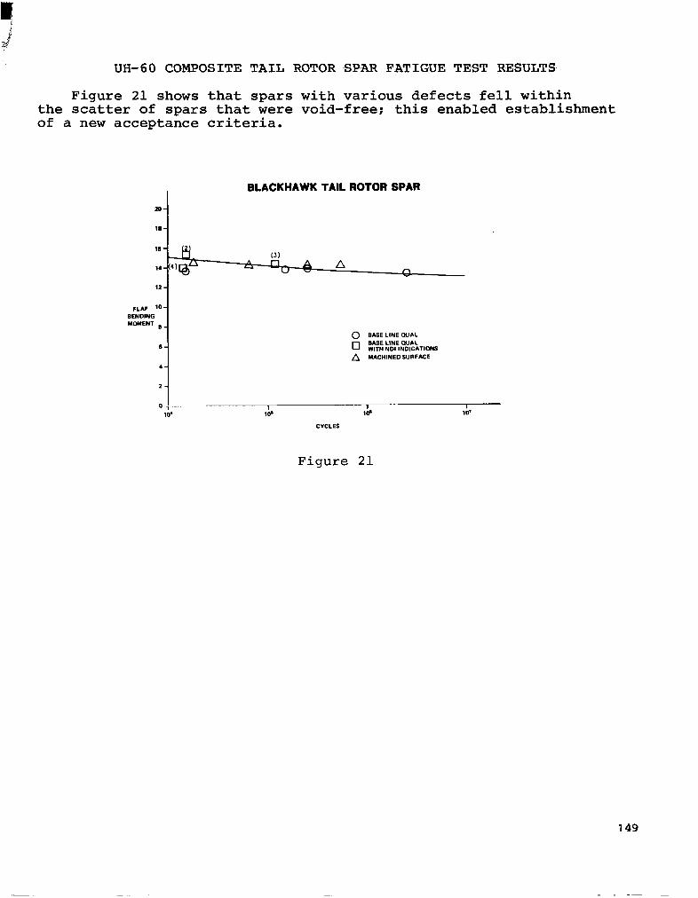
Figure 21 shows that spars with various defects fell within the scatter of spars that were void-free; this enabled establishment of a new acceptance criteria.
BLACKHAWK TAIL ROTOR SPAR
Figure 21

SUMMARY/CONCLUSIONS
Helicopter flight-critical structures, although limited primarily to rotor blades, have been successfully designed for damage tolerance. This has been accomplished through redundancy, use of damage-tolerant materials and sizing to JLOW operating stress levels. Design and demonstration have been based on laboratory testing.
The increased application of composites to more complexly loaded structures, such as bearingless rotor hubs which inherently will operate a$ higher strain levels, further amplifies the need for a sound damage- tolerant criterion. Development of the criterion must address those items listed in the last bullet of Figure 22.
o LABORATORY TESTING THE BASIS FOR DESIGN AND DEVELOPflENT OF DAMAGE TOLERANT COMPOSITE STRUCTURES
o DAMAGE TOLERANT CRITERIA FOR COMPOSITES NEEDED, ESPECIALLY IN LIGHT OF
- COMPOSITES APPLICATION TO MORE COMPLEXLY LOADED COMPONENTS
- INCREASED STRAIN LEVELS
o DAMAGE TOLERANT CRITERIA DEVELOPMENT MUST INCLUDE
- PREDICTIVE CAPABILITY
- DAMAGE SIZE REQUIREMENTS
- NDT CAPABILITY/DAMAGE DETECTABILITY
- DESIGN REQUIREMENTS
- ENVIRONNENTAL EFFECTS
- TEST/QUAL REQUIREMENTS
Figure 22
150
L ‘

1.
2.
3.
4.
5.
6.
7.
a.
9.
10
AA. Weiss, W. L.; and Zola, D. C.: 11 The Application of Fracture Mechanics to the Desgin of Damage Tolerant Components for the UTTAS Helicopter. Paper presented at 30th Annual AHS Forum (Washington, D.C.), May 7-9, 1974.
REFERENCES
Helicopter Fatigue - A Review of Current Requirements and Substan- tiating Procedures. AGARD Report No. 674, Feb. 1979.
Proceedings of the AHS Midwest Region Helicopter Fatigue Method- ology Meeting (St. Louis, MO) .' March 23-25, 1980.
Nobak, R.: State of the Art and Statistical Aspects of Helicopter Fatigue Substantiation Procedures. Helicoptei Fatigue Life Assessment, AGARD Conference Proceedings No. 297, March 1981.
Immen, F. H.: Failsafe vs Safe Life Philosophy in V/STOL Design. J. Am. Helicopter Sot., vol. 14, no. 4, Oct. 1969.
Cansdale, R.: An Evaluation of Fatigue Procedures for UK,Military Helicopters. Helicopter Fatigue Life Assessment, AGARD Confer- ence Proceedings No. 297, March 1981.
Polley, I. M.: Damage Tolerance Design for Helicopter Structural Integrity. Paper presented at Second European Rotorcraft and Power Lift Aircraft Forum (Buckeburg, Germany), September 1976.
Toor, P. M.; and Payne, B. M.: Damage Tolerance Design and Analysis of a Typical Aircraft Wing Strucure (New or Existing). Case Studies in Fracture Mechanics, T. P. Rich and D. J. Cartwright, eds., AMMRC-MS-77-5, Army Materials and Mechanics Research Center, June 1977.
Field, D. M.; Finney, R. H.; and Stratton, W. K.: Achieving Fail Safe Design in Rotors. Paper presented at 28th Annual AHS Forum (Washington, D.C.), May 17-19, 1972.
McCall, C. D.; Field, D. M.; and Reddick, H. K.: Advanced Tech- nology as Applied to the Design of the HLH Rotor Hub. Paper presented at 29th Annual AHS Forum (Washington, D.C.), May 9-11, 1973.
Smith, H. G.: Fail Safe Structural Features of the Hughes OH-6A. Paper presented at Second European Rotorcraft and Power Lift Forun.(Buckeburg, Germany), September 1976.
.
151