safe drinking water for your small water system: an · pdf file · 2017-02-15safe...
TRANSCRIPT

Safe Drinking Water for Your Small Water System: An Operator's Guide

ACKNOWLEDGEMENTS
Publication of this manual was made possible through a grant from the Minnesota
Department of Health, Drinking Water Protection Section to the Minnesota Rural Water Association.
The expertise of many individuals have been utilized to bring together an overview of key
elements of the operation and maintenance of very small water systems. Some of those individuals from the Minnesota Department of Health include; Dave Hokanson, Jerry Smith, Paul Felling, Cindy Cook, Joyce Hedlin, Dan Houg, and Milt Bellin.
Jennifer Lerdahl, Minnesota Rural Water Association, Technical Advisor for the
nontransient noncommunity water systems was the Project Manager and major contributing author for the manual. Other contributors from the Minnesota Rural Water Association include Don Christianson, Lori Blair and Ruth Hubbard.
A special thank you to water industry personnel and professional associations for the use of
photographs, graphics and illustrations for the manual.
i

Disclaimer
Several photographs and illustrative drawings that appear in this manual have been furnished through the courtesy of various product distributors and manufacturers. Any mention of trade name, commercial products or services does not constitute endorsement or recommendation for use by the Minnesota Department of Health or the Minnesota Rural Water Association.
This manual presents a summary of regulations applicable to small drinking water systems. Should the summarized information in this document be inconsistent with a governing rule or statute, the language of the rule or statute shall prevail.
First Publication Date: Summer 2002
Copyright© 2002 Minnesota Department of Health This manual may be reproduced, in whole or in part, for educational purposes only. Please credit the "Minnesota Department of Health/Minnesota Rural Water Association" if any portion of this manual, including photographs, is used in another publication.
Minnesota Department of Health Section of Drinking Water Protection
121 East Seventh Place, Suite 220 P.O. Box 64975
St. Paul, MN 55164-0975 Phone: 651/215-0700
Web: http://www.health.state.mn.us
Minnesota Rural Water Association 1311 Highway 79 East
Elbow Lake, MN 56531 Phone: 800/367-6792
Fax: 218/685-5272 E-mail: [email protected]
Web: http://www.mrwa.com
ii

iii
TABLE OF CONTENTS Introduction....................................................................................................................................... 1 Chapter 1: Key Points in Operating and Maintaining Your Water System............................. 3 Chapter 2: Public Water Systems, Roles and Requirements...................................................... 5 Chapter 3: Drinking Water Contaminants and Sampling Requirements................................. 15 Chapter 4: Groundwater and Wells............................................................................................... 25 Chapter 5: Storage and Pressure Tanks ........................................................................................ 35 Chapter 6: Treatment ...................................................................................................................... 41 Chapter 7: Water Distribution System.......................................................................................... 45 Chapter 8: Cross Connections and Backflow Prevention.......................................................... 49 Chapter 9: Water System Security and Emergency Planning .................................................... 55 Appendix A: Isolation Distances ................................................................................................... 57 Appendix B: Well Disinfection...................................................................................................... 59 Appendix C: Contact Information ................................................................................................ 65 Appendix D: Drinking Water Standards....................................................................................... 79 Appendix E: Record Keeping Requirements .............................................................................. 83 Appendix F: Plan Review............................................................................................................... 85 Appendix G: Sample Lab Result Forms ....................................................................................... 95 Appendix H: Public Notices........................................................................................................... 99 Appendix I: Waterborne Diseases ............................................................................................... 107 Appendix J: Coliform Bacteria Sampling Procedure................................................................. 109 Appendix K: Aesthetic Issues ........................................................................................................ 111 Appendix L: Well Log..................................................................................................................... 113 Appendix M: Well Sealing Log ....................................................................................................... 115

iv
Appendix N: Chapter 4715.2110 Approved Backflow Prevention Devices ........................... 117 Appendix O: Emergency Plan Template ...................................................................................... 119 Appendix P: Funding Resources................................................................................................... 121 Appendix Q: Definitions................................................................................................................. 129 Appendix R: Web Resources ......................................................................................................... 133 Appendix S: References ................................................................................................................. 135

___________________________________________________________________ Introduction
Introduction This manual is intended to provide basic information for the operators of small public water systems, primarily "Class E" nontransient and nonmunicipal public water system operators. It may also be of use for the operators of other small systems. Your water supply is critical to the operation of your facility. It may supply drinking water, water for food preparation, water for washing, process water, or other uses. Whether you operate a system serving a school, business, factory, manufactured housing park, or other facility, an uninterrupted, safe supply of water is necessary for your daily operations. Additionally, state and federal regulations require you to provide a safe and adequate supply of water. Knowing about your water system, operating it properly, and performing preventative maintenance can help avoid unsafe, costly, and inconvenient problems with your water system. This manual has been developed to provide you with some basic information to assist you in operating your water system and serving safe drinking water. The manual also gives you background information on how water systems work and the regulations applied to public water systems. The manual is organized into nine different chapters. The first chapter summarizes some key points in operating your water system and the following chapters address specific regulations and operational issues.
Introduction 1

Introduction ___________________________________________________________________
2 Introduction

_____________________________________________________________________ Chapter 1
Chapter 1 Key Points in Operating and Maintaining Your Water System This chapter contains basic information about what you can do to ensure that your water system remains safe and in good condition. Later chapters provide more detail about these topics. The following are essential elements in the operation of your water system:
Know the location of your well(s) and inspect the well(s) on a routine basis. Inspecting the well will alert you to any deterioration, damage, or other problems.
Provide a secure and intact well cap. Older well caps often do a poor job of keeping insects and dirt out of the well. If possible, replace older caps with an overlapping well cap that includes a compression gasket and screened vent. See the “Well Components” section of Chapter 4 for more information.
Be sure the well casing extends at least one foot above the ground surface to reduce the possibility of surface water or other contaminants entering the well. Avoid landscaping projects that reduce the distance between the ground and the top of the well casing to less than the required minimum distance. If necessary, a licensed well driller can extend the well casing to the proper height. See the “Well Components” section of Chapter 4 for more information.
Direct surface and roof runoff away from the well. Surface water should not collect near the well.
Protect wells from potential vehicle damage. Delivery trucks, lawnmowers, snowmobiles, and other vehicles may damage wells. Sometimes the damage to the well is below ground and not visible from the surface. Water quality degradation, inconvenience, and expensive repairs are often the end result. Direct vehicular traffic away from the well or surround the well casing with rigid posts or large rocks to help protect the well from damage. See the “Well Casing Protection” section of Chapter 4 for more information.
To the extent possible, remove any potential sources of contamination from the area near the well. All new wells must meet the minimum requirements for separation from potential contaminant sources. Required minimum isolation distances are listed in Chapter 4 and in Appendix A.
Key Points in Operating and Maintaining Your Water System 3

Chapter 1 ___________________________________________________________________
Operate and maintain all water treatment devices according to the manufacturer’s specifications. This includes routine replacement of filter cartridges and maintaining an adequate level of salt in the brine tank, if you have a water softener. Poorly maintained treatment devices often lead to water quality problems. See Chapter 6 for more information on water treatment devices.
Eliminate cross connections and dead ends in the plumbing system. A dead end, as the name implies, is a portion of your drinking water piping that does not have water regularly moving through it. Dead ends result in stagnant water that deteriorates and can affect water quality elsewhere in the system. Plumbing cross connections potentially allow contaminants to enter the potable water supply. See Chapter 8 for more information on cross connections.
Always disinfect the plumbing system after repairs or modifications. New fixtures, piping, or other plumbing components can introduce bacterial contamination. All seasonal wells and plumbing systems should be disinfected prior to start-up. Be sure to thoroughly flush all lines before returning to use. Disinfection instructions are available in Appendix B.
Designate an individual (perhaps yourself!) to become the certified water operator for the system. Make sure that individual receives certification from the state and attends continuing education classes. See the “Operator Certification Requirements” section of Chapter 2 for more information.
Prior to making changes to the water system, determine if plan review is needed. If it is, make sure that plans are reviewed and approved by the Minnesota Department of Health (MDH) before proceeding. See the “Plan Review for Public Water Systems” section of Chapter 2 for plan review requirements.
Know whom to contact in case of emergency if there are problems with your water system. This would include MDH staff, a well contractor, and a plumber. See Appendix C for contact information.
These key points will help you in maintaining a safe, reliable source of water. The following chapters will provide you with further information in operating your system and meeting legal requirements. Keep reading to learn more about your water system!
4 Key Points in Operating and Maintaining Your Water System

_____________________________________________________________________ Chapter 2
Chapter 2 Public Water Systems, Roles and Requirements What is a Public Water System? Why is My Facility a Public Water System? If your facility has its own water supply (i.e. a well) and serves 25 or more people for at least 60 days a year, it is considered a “Public Water System” under the Federal Safe Drinking Water Act (SDWA). Keep in mind that “serving water” means that water is used for any of the following purposes: drinking, food preparation, bathing, showering, tooth brushing, or dishwashing. All public water systems are required to meet the legal requirements of the Federal SDWA as it is implemented here in Minnesota. Figure 2.1 on page 6 illustrates the specific types of public water systems defined by the SDWA. What Regulations Apply to Public Water Systems?
The Federal Safe Drinking Water Act (SDWA) is the principal regulation governing public water systems in Minnesota. It defines what a public water system is, sets drinking water quality standards, institutes water sampling and survey schedules, establishes requirements for source water protection and operator certification, and more. Minnesota Rules, Chapter 4720 adopts the SDWA by reference with
some amendments and also includes sections on Wellhead Protection. Other significant Minnesota Rules that apply to public water systems are the Minnesota Plumbing Code (Chapter 4715), Wells and Borings (Chapter 4725), and Water and Wastewater Treatment Operator Certification (Chapter 9400).
Drinking Water Regulations
Federal Safe Drinking Water Act Minnesota Safe Drinking Water Rules
Minnesota Well Code Minnesota Plumbing Code
Minnesota Operator Certification Rules
Rules Available on the Internet
A quick way to look up the regulations that affect your water system is to look on the internet.Here are some resources you can use:
• Minnesota Rules (Safe Drinking Water, Well Code, Plumbing Code, OperatorCertification) are available at www.leg.state.mn.us/leg/statutes.htm
• The Federal Safe Drinking Water Act and related rules (40 CFR 141 and 142) areavailable at www.epa.gov/OGWDW
• For further information, go to the MDH Drinking Water Protection website atwww.health.state.mn.us/divs/eh/water/index.html
Public Water Systems, Roles and Requirements 5

Chapter 2 ___________________________________________________________________
6 Public Water Systems, Roles and Requirements

_____________________________________________________________________ Chapter 2
Responsibilities of the Owner and Operator The owner of a public water system is responsible for meeting all of the legal requirements that apply to the water supply. An operator is a person who conducts day-to-day operational and technical activities related to the operation of a water supply. Although the owner may designate an operator, the owner is ultimately responsible for providing safe drinking water and meeting regulatory requirements. It is important that both the owner and operator work together to ensure that the water system provides safe drinking water and meets all applicable requirements. The ultimate goal for both the owner and operator is to provide safe drinking water to the public. Responsibilities of the Public Water System and MDH in Providing Safe Drinking Water The public water system owner and operator, along with MDH, work together to make sure that safe drinking water is provided to water system users and that all regulatory requirements are met. The charts on the following pages summarize the responsibilities of the public water system and MDH in this partnership. Some of the items listed will be described in more detail later in the manual.
Public Water Systems, Roles and Requirements 7

Chapter 2 ___________________________________________________________________
Meet Drinlegally enfoexceed the and Append
Public Noestablished Chapter 3 fo
Certified Odesignate at“Operator C
Sampling –water systemand monthrequiremen
Source Wapreventing public wateisolation dicommunity MDH staff.
Well Coderequiremeninformation
Plumbing requiremenadditional in
Plan Revietreatment sreview, see
Record Kekept on filepremises. Se
Capacity Dmust demoReview ford
Consumer
evelopmen
quality repowater systeminformationdrinking wamonitoring community water syste
8 Public Water Sy
Public Water System’s Responsibilities in Providing Safe Drinking Water
king Water Standards – The water supplied by the water system must meet all established,rceable drinking water standards. Water testing must show that the water quality does notestablished maximum contaminant level (MCL) for each regulated contaminant. See Chapter 3ix D for more information on drinking water standards.
tification – Each public water system must notify its customers when it does not meet andrinking water standard. See the “Public Notification and Alternative Water Source” section ofr more information.
perator – Each nontransient noncommunity and community public water system must least one water system operator. This operator must be certified by the State of Minnesota. Seeertification Requirements” at the end of this chapter for more information.
Although MDH program staff accomplishes most SDWA compliance monitoring, the public is still responsible for some sampling. This monitoring may include lead and copper sampling
ly/quarterly bacteriological sampling. See Chapter 3 for more information on samplingts.
ter Protection – Source water protection (also known as wellhead protection) involvescontamination of your water supply by effectively managing potential sources of pollutants. Allr systems are required to implement source water protection measures, such as meeting allstances for potential contaminant sources. Additionally, all nontransient noncommunity andpublic water systems will develop a formal wellhead protection plan, with assistance from
See “Source Water Protection” at the end of this chapter for more information.
Compliance – Installation of new wells and modifications of existing wells must meet thets of the Minnesota Well Code (Minnesota Rules, Chapter 4725). See Chapter 4 for additional on well specifications.
Code Compliance – All installation and modification of plumbing components must meet thets of the Minnesota Plumbing Code (Minnesota Rules, Chapter 4715). See Chapters 7 and 8 forformation on plumbing requirements.
w – Plans must be submitted for changes or additions to plumbing, installation of a new waterystem or changes made to an existing treatment system. For more information about plan“Plan Review for Public Water Systems” at the end of this chapter.
eping – Records of sampling, sanitary surveys, and other correspondence from MDH must be by the water system. It is recommended that all information be kept at one location on thee Appendix E for record keeping requirements.
evelopment – All new nontransient noncommunity and community public water systemsnstrate technical, managerial, and financial capacity before beginning operation. See “Plan Public Water Systems” at the end of this chapter for more information about cap
Confidence Report (CCR) – All community water systems must provide an annual wate
t.
rrt called a Consumer Confidence Report (CCR) to their customers. Each year, all community
s will receive a ready-to-go report from MDH. The operator will need to complete some for the report. The goal of the CCR is to provide information to customers about theirter. The reports must be completed and distributed by July 1 of each year and will coveractivities through the end of the previous calendar year. See Appendix C for a list of MDHcontact persons if you have questions about CCRs. This requirement applies to communityms only.
acity
stems, Roles and Requirements
_____________________________________________________________________ Chapter 2
MDH’s Roles and Responsibilities in Providing Safe Drinking Water
Sampling – MDH program staff accomplishes most SDWA compliance monitoring. Water systems aretested at least annually for total coliform bacteria and nitrate. Water systems are also tested for chroniccontaminants such as pesticides. The frequency of monitoring of the chronic contaminants is establishedby the vulnerability of the source, well construction, and historical monitoring results. See Chapter 3 formore information about sampling requirements.
Sanitary Survey – A sanitary survey is an on-site review of the adequacy of the water source, facilities,equipment, operation and maintenance of a public water system for producing and distributing safedrinking water. The sanitary survey includes inspection of: source water; treatment; distribution system(including cross connection control); finished water storage; pumps and controls; monitoring, reporting,and data verification; and water system operation and management (operator certification for nontransientwater systems). MDH conducts sanitary surveys for noncommunity water systems every three years, while asanitary survey for a community system is conducted every 18 months.
Technical Assistance – MDH staff provide on site technical assistance to public water systems. This is acritical function when contamination has been confirmed in a water system. Technical assistance is alsoprovided on routine issues such as water system operation, sampling, and regulatory requirements.
Plan Review – MDH performs plan review for public water systems. Any changes or additions toplumbing, installation of a new water treatment system or any changes made to an existing treatmentsystem, and certain sewage treatment systems for public water systems require a plan review. See “PlanReview for Public Water Systems” at the end of this chapter for more information.
Source Water Protection – MDH staff will assist public water systems in identifying source waterprotection measures and in developing wellhead protection plans. See “Source Water Protection” at theend of this chapter for more information.
Lab Certification – Laboratories that perform water analysis throughout Minnesota are required to becertified by MDH. All samples submitted for compliance with state and federal rules must be submitted toa certified lab. Labs must meet MDH criteria in order to become certified and must also maintaincertification. Be aware that not all labs meet MDH criteria.
Training and Education – MDH provides training and educational materials to public water supplies.Newsletters and continuing education classes are also offered.
MDH Contact Persons – Refer to Appendix C for MDH contact persons for any questions or forassistance regarding your water supply.
Consumer Confidence Report (CCR) – All community water systems will receive a ready-to-go CCRreport each year from MDH. The operator may need to complete some information in the report. SeeAppendix C for a list of MDH contact persons if you have any questions about CCRs.
Public Water Systems, Roles and Requirements 9
Chapter 2 ___________________________________________________________________
Summary of Requirements for Plan Review, Operator Certification, and Source Water Protection A few of the requirements for public water systems will be addressed in the remainder of this chapter: plan review, operator certification, and source water protection. Other requirements (as listed in the chart on page 7) will be addressed in detail in the later chapters of this manual. Plan Review for Public Water Systems
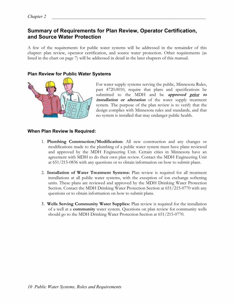
For water supply systems serving the public, Minnesota Rules, part 4720.0010, require that plans and specifications be submitted to the MDH and be approved prior to installation or alteration of the water supply treatment system. The purpose of the plan review is to verify that the design complies with Minnesota rules and standards, and that no system is installed that may endanger public health.
When Plan Review Is Required:
1. Plumbing Construction/Modification: All new construction and any changes or modifications made to the plumbing of a public water system must have plans reviewed and approved by the MDH Engineering Unit. Certain cities in Minnesota have an agreement with MDH to do their own plan review. Contact the MDH Engineering Unit at 651/215-0836 with any questions or to obtain information on how to submit plans.
2. Installation of Water Treatment Systems: Plan review is required for all treatment
installations at all public water systems, with the exception of ion exchange softening units. These plans are reviewed and approved by the MDH Drinking Water Protection Section. Contact the MDH Drinking Water Protection Section at 651/215-0770 with any questions or to obtain information on how to submit plans.
3. Wells Serving Community Water Supplies: Plan review is required for the installation
of a well at a community water system. Questions on plan review for community wells should go to the MDH Drinking Water Protection Section at 651/215-0770.
10 Public Water Systems, Roles and Requirements

_____________________________________________________________________ Chapter 2
When Plan Review Is Not Required: Plan review is not required for the following two items, however, each has certain requirements that must be completed before construction begins.
1. Wells Serving Nontransient Noncommunity Water Supplies: Plan review is not required for nontransient noncommunity wells, however, the well driller is required to send in a well notification, and the MDH Well Management Unit will conduct an inspection of the well. Any questions on new wells should be directed to the MDH Well Management Unit at 651/215-0811.
2. Capacity Development: For all new nontransient noncommunity and nonmunicipal
community water systems, capacity development requirements must be met. This process basically requires the water system to verify Technical, Managerial and Financial capacity by coordinating the plan review and inspection processes. Any questions on Capacity Development should be directed to the MDH Drinking Water Protection Section at 651/215-0770.
Plan Review Application Forms Examples of the applications used for plumbing plan review and nitrate treatment plan review are available in Appendix F. Operator Certification Requirements All nontransient noncommunity (NTNC) and community water systems are required to have at least one certified operator. These systems are all placed into an operator certification class (A through E), based on factors such as the complexity of treatment and the number of people they serve. Most NTNC water systems and nonmunicipal community water systems will fall into the “lower” categories - either a Class D or E water system classification. The following items designate the certification qualifications for both Class D and E water operators. Certification Requirements for Class D and E Operators
• All applicants must have a high school diploma or equivalent.
• A Class D applicant must have at least one year of experience in the operation of aClass A, B, C, or D system.
• A Class E applicant must have at least three months of experience in the operation ofa Class A, B, C, D, or E system.
This is only a short summary of the Water Supply Operator qualifications. For moreinformation, contact the MDH Drinking Water Protection Section at 651/215-0770.
Public Water Systems, Roles and Requirements 11

Chapter 2 ___________________________________________________________________
Operator Certification Procedure If an individual does not qualify for grandparenting (see below), the following must be completed to become a certified operator:
1. Complete and mail an exam application to MDH with the exam fee. The individual may be required to submit copies of educational and operating experience;
2. Pass an exam prepared by MDH with a score of 70 percent or better. Upon notification of passing the exam, the individual must apply for the certificate within 90 days and pay the certificate fee;
3. Upon receiving the application and fee for the certificate, MDH will issue the certificate.
Grandparenting An operator that starts work at a water system after October 1, 2001, will be required to take the certification exam to become a certified operator. If an employee was employed as an operator of the NTNC water system before October 1, 2001, that employee could become certified without taking a test. This is referred to as “grandparenting.” The grandparenting option expires on October 1, 2003. After October 1, 2003, all operators, regardless of when they were employed, may not become certified without passing a test. Renewal of Certificates All operators, whether “grandparented” or not, will need to complete continuing education in order to renew their certificates and remain certified. The amount of continuing education hours will depend on the system’s classification. Operator certification certificates are valid for three years. The continuing education must be completed before the certificate expires.
Certification Class
Contact Hours
A 32 B 24 C 16 D 8 E 4
For More Information
For more information, contact the MDH Drinking Water Protection section at 651/215-0770. See also the list of contact persons in Appendix C.
12 Public Water Systems, Roles and Requirements

_____________________________________________________________________ Chapter 2
Source Water Protection (SWP) Drinking water contamination creates potential health problems and increases expenses for well owners as they seek to correct the problem. From both a health and cost perspective, it is preferable to prevent contamination from happening in the first place. Because preventing contamination is so important, all public water systems in Minnesota – including NTNC public water supplies – are required to implement “source water protection.” For groundwater systems, “wellhead protection” has the same meaning as “source water protection.” The following items briefly describe the responsibilities of the water supply and MDH.
F
W SycAwp
Public Water Supply Roles in Source Water Protection
• Be sure that any new contamination sources meet the isolation distances defined in theMinnesota Well Code.
• Monitor (or relocate) all existing contamination sources that don’t meet the requiredisolation distance.
• Implement wellhead protection measures for contaminant sources within your innerwellhead management zone (IWMZ) – the area within 200 feet of your well in alldirections. These measures include performing maintenance, educating staff, changingwork practices, or moving potential contaminant sources.
• Develop and implement your wellhead protection plan.
MDH Roles in Source Water Protection
• MDH staff will assist you in developing your wellhead protection plan.
• MDH will provide assistance in identifying potential contaminant sources and inselecting appropriate wellhead protection measures.
or More Information For more information, contact the MDH Source Water Protection Unit at 651/215-0800. See also the list of contact persons in Appendix C.
ho Can Help Me in Meeting Requirements?
taff of the MDH collect water samples and will provide you with technical assistance in operating our water system and meeting regulatory requirements. At times, you may also need to hire a well ontractor, licensed plumber, or other water professional to assist you with your water system. dditionally, there are independent organizations, such as the Minnesota Rural Water Association, hich can provide advice and recommendations regarding your water system. A list of contact ersons is provided in Appendix C.
Public Water Systems, Roles and Requirements 13

Chapter 2 ___________________________________________________________________
14 Public Water Systems, Roles and Requirements
_____________________________________________________________________ Chapter 3
Chapter 3 Drinking Water Contaminants and Sampling Requirements Introduction
There are potentially thousands of different contaminants that could find their way into drinking water systems that may be harmful to health. It would be impractical as well as impossible to attempt to test for all possible contaminants. Priorities for testing are determined, in general, by the federal government – which decides which impurities to monitor based on national occurrence data and health effects for specific contaminants.
Currently in Minnesota, microbiological contaminants (coliform bacteria), inorganic chemicals, volatile organic compounds, and synthetic organic compounds are being monitored at nontransient noncommunity and nonmunicipal community water systems. Radiological contaminants are also being monitored at nonmunicipal community water systems. Acute vs. Chronic Contaminants The types of contaminants that are monitored include both acute and chronic contaminants. Acute contaminants may have the potential to pose an immediate health risk if consumed. Acute contaminants are tested at all public water supplies. Nitrate and E. coli are examples of acute contaminants. Most contaminants are considered chronic, meaning that cancer or other ill health may result if the contaminant is consumed at relatively low concentrations over extended periods of time. Benzene and lead are examples. Chronic contaminants are monitored at only community and nontransient systems because people served by these systems may consume the water for extended periods of time. Maximum Contaminant Level (MCL) and Action Level (AL) A maximum contaminant level (MCL) has been set by US EPA for each regulated contaminant. The MCL is the greatest amount of a particular contaminant allowed in drinking water. This is a standard set by US EPA and enforced by MDH. An action level (AL) is a contaminant concentration that if reached in a certain percentage of samples requires specified actions by the public water supply. Lead is an example of a contaminant assigned an AL rather than an MCL.
Drinking Water Contaminants and Sampling Requirements 15
Chapter 3 ___________________________________________________________________
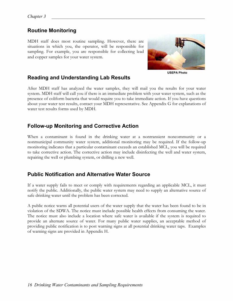
Routine Monitoring MDH staff does most routine sampling. However, there are situations in which you, the operator, will be responsible for sampling. For example, you are responsible for collecting lead and copper samples for your water system. USEPA Photo
Reading and Understanding Lab Results After MDH staff has analyzed the water samples, they will mail you the results for your water system. MDH staff will call you if there is an immediate problem with your water system, such as the presence of coliform bacteria that would require you to take immediate action. If you have questions about your water test results, contact your MDH representative. See Appendix G for explanations of water test results forms used by MDH. Follow-up Monitoring and Corrective Action When a contaminant is found in the drinking water at a nontransient noncommunity or a nonmunicipal community water system, additional monitoring may be required. If the follow-up monitoring indicates that a particular contaminant exceeds an established MCL, you will be required to take corrective action. The corrective action may include disinfecting the well and water system, repairing the well or plumbing system, or drilling a new well. Public Notification and Alternative Water Source
If a water supply fails to meet or comply with requirements regarding an applicable MCL, it must notify the public. Additionally, the public water system may need to supply an alternative source of safe drinking water until the problem has been corrected. A public notice warns all potential users of the water supply that the water has been found to be in violation of the SDWA. The notice must include possible health effects from consuming the water. The notice must also include a location where safe water is available if the system is required to provide an alternate source of water. For many public water supplies, an acceptable method of providing public notification is to post warning signs at all potential drinking water taps. Examples of warning signs are provided in Appendix H.
16 Drinking Water Contaminants and Sampling Requirements

_____________________________________________________________________ Chapter 3
Regulated Contaminants: Microbiological Coliform Bacteria Although it is not a common occurrence, disease causing bacteria, viruses, and protozoa can sometimes find their way into drinking water supplies and cause human illness. Some of the waterborne diseases of concern in the United States are listed in Appendix I. Not all disease-producing organisms present in water are known or easily identifiable. For these reasons, the standard approach for identifying microbiological contamination is to look for “indicator organisms” called coliform bacteria. Coliform bacteria quickly and inexpensively gives an indication that disease-causing organisms may be present. The total coliform group of bacteria has been selected by the US EPA and MDH as the indicator to be used in testing the microbiological quality of drinking water. Coliform bacteria are not considered a normal inhabitant of groundwater or disinfected surface water. Their presence suggests that disease-causing organisms may have gained entry because a breach or malfunction has occurred somewhere in the drinking water system. While coliform bacteria themselves pose little health risk, their presence indicates that the water may be unsafe because of the potential presence of other health threatening microbiological organisms. Coliform Bacteria Sampling The MDH typically samples for coliform bacteria on an annual basis at noncommunity water systems. Community systems typically collect their own coliform samples at least once per quarter. Increased monitoring may be necessary if the water system has been found to contain coliform bacteria, has a history of coliform contamination, or serves a population over 1,000. Any samples that indicate the presence of total coliform will be further analyzed for E. coli. Appendix J illustrates the coliform bacteria sampling procedure used by MDH for nontransient noncommunity systems that are on annual monitoring.
Drinking Water Contaminants and Sampling Requirements 17

Chapter 3 ___________________________________________________________________
What Happens When Coliform Bacteria are Present?
R Tcc
Tpwt T DTcc
1
When coliform bacteria and/or E. coli are present in drinking water, the following steps must be taken:
• MDH staff will collect follow-up bacteria samples to confirm the contamination. Ifcontamination is confirmed, the steps listed below are to be completed. Ifcontamination is not confirmed, no further action is required of the system and MDHmay collect an additional sample in 30 days.
• MDH will conduct an inspection of the water system. You may also hire a wellcontractor or plumber to inspect the water system.
• The water system must correct any identified deficiencies found during theinspection(s). Any work performed on the well must be performed by a licensedwell contractor.
• The entire water system must be thoroughly disinfected. Disinfection instructions areavailable in Appendix B. It is necessary for all the disinfectant to be thoroughly flushedfrom the system prior to any MDH follow-up sampling.
• Until such time that sampling by MDH staff verify that the coliform organisms are nolonger present, the water system must provide public notification to the water supplyusers that the system is contaminated. Refer to the public notices in Appendix H foradditional information.
• The water supply system may be required to restrict water usage as required by MDH.The water system may also be required to supply water from an approved source.
equirements if Escherichia Coli (E. Coli) is Present
he presence of E. coli or fecal coliform is a more serious situation than the presence of total oliform alone. E. coli or fecal coliform presence indicates that human or animal fecal material has ontaminated the water system and any ingestion of this water poses a serious health threat. he public water system needs to act promptly, notify the public, restrict the use of water, and rovide an alternative water supply (for noncommunity systems) until the problem is corrected. The ater must not be consumed in any way. Water users should be aware of potential consumption
hrough food preparation, making ice, brushing teeth and washing dishes.
roubleshooting and Correcting Bacteriological Contamination
etermining the cause of bacteriological contamination may be difficult and each case is unique. able 3.1 on page 19 can provide you a place to start in looking at some of the most common auses of bacteriological contamination. Once a likely cause has been determined, appropriate orrective action can be taken.
8 Drinking Water Contaminants and Sampling Requirements

_____________________________________________________________________ Chapter 3
Table 3.1 Common Causes of Coliform Problems in Water Supplies and Corrective Actions
CAUSE OF COLIFORM PROBLEM PREVENTION / CORRECTIVE ACTION
Lack of proper maintenance on treatment units such as carbon filters, sediment filters, water softeners, etc. The treatment unit itself offers surface area for bacterial growth and also may concentrate organic material for bacteria to utilize as a food source.
Replace filter cartridges as recommended by the manufacturer. Sanitize the filter housing with a dilute bleach/water solution when replacing cartridges. Maintain salt in water softener brine tanks.
Plumbing repairs or additions without system disinfection can introduce bacteria and subsequent growth is possible especially in non-chlorinated systems.
Always disinfect water systems after plumbing repairs or additions.
Seasonal systems can have coliform introduced during draining, startup, or anytime if drained water lines are not properly closed or capped in the fall.
Never leave any part of the plumbing system open to the environment. Always disinfect the well and plumbing each spring.
Dead ends in the plumbing system allow water to become stagnant and sediment to accumulate creating conditions favorable for bacterial growth. Dead ends are created when plumbing fixtures are removed or taken out of service and the associated water lines are left in place. Dead ends can also exist on water feed lines to fire and lawn sprinkler systems, boilers, heat exchangers, church baptisteries, and other seasonal or seldom used fixtures.
Remove all unnecessary plumbing dead ends. Routinely run water through seldom-used fixtures. Ensure that feed lines to lawn sprinkler systems and boilers have proper backflow prevention installed.
Water systems with very low water use in effect are dead ends and this may promote bacterial growth.
Periodically flush the water system by lawn sprinkling or other means.
Coliform bacteria can enter systems through well caps especially if well caps or sanitary seals are not weather and insect proof, or are damaged, loose fitting, or missing.
Install new style weather and insect proof well caps that seal tightly to the casing with a compression fitting. Replace damaged sanitary seals.
When a submersible pump is replaced and the well is not adequately disinfected, coliform may be introduced on the new pump or from the drop pipe or wiring if set on the ground.
Prevent drop pipes and wiring from becoming soiled during pump replacement. Disinfect the well and plumbing after pump replacement.
Wells located in pits are prone to bacterial contamination when the pit floods and water enters the well via the cap or vent.
Hire a licensed well contractor to extend the well casing at least 12 inches above ground level and fill in the pit or replace the well.
Well casing that terminates near or at the ground surface allows surface water to enter the top of the well through the well cap or vent.
Hire a licensed well contractor to extend the well casing at least 12 inches above the surrounding ground level.
Well casing that becomes damaged when struck by a vehicle. Coliform bacteria enter the well via surface water and surrounding soil draining into the well. The damage may exist below the ground surface and not be apparent.
Wells located in areas where vehicular traffic occurs should be protected by surrounding the casing with rigid posts, large rocks, or fencing. Avoid locating new wells in traffic areas.
Drinking Water Contaminants and Sampling Requirements 19

Chapter 3 ___________________________________________________________________
Regulated Contaminants: Chemical In addition to monitoring water supplies for coliform bacteria, the MDH also monitors for chemical contaminants that are known to cause health problems including nitrate, arsenic, lead, copper, other inorganic chemicals (e.g. metals), synthetic organic compounds (e.g. pesticides), and volatile organic compounds (e.g. solvents). Table 3.2 on page 21 describes regulated drinking water contaminant groups, applicable MCLs, contaminant sources, health effects, monitoring frequency, and sample collectors for each contaminant listed. MDH staff are available to assist water systems in addressing elevated levels of chemical contaminants. Internet Photo Inorganic Contaminants Inorganic chemicals include metals, salts, and other compounds. Among the most commonly found inorganic chemical contaminants are nitrate, arsenic, and lead – these are discussed in greater detail in the following sections. Nitrate Soil microorganisms change nitrogen containing substances in fertilizer, animal and human wastes, and decaying vegetation into nitrates. Nitrate readily moves with water through soil and into groundwater. Infants that consume water high in nitrates are susceptible to a life-threatening disease called methemoglobinemia or “blue baby” syndrome. Babies with this condition become oxygen starved because their red blood cells are unable to carry oxygen properly. Infants become less susceptible to the effects of nitrates after six months of age. The MCL for nitrate nitrogen is 10.0 mg/L. Public water systems that exceed this level are required to obtain a new water source or treat their water. Anion exchange, reverse osmosis, and distillation are treatment technologies that can effectively remove nitrate. (Consult with MDH staff if you are considering treatment for nitrate removal.) Arsenic Arsenic is a naturally occurring element in soil and bedrock. Bedrock and underground soil can release arsenic that works its way into groundwater. Usually, naturally occurring arsenic is the most common source of arsenic in drinking water. Although the amounts of arsenic that occur naturally in groundwater do not present immediate health concerns, long-term consumption of water with arsenic over the MCL of 10 micrograms per liter (ug/L) may cause problems with skin, circulation, the lungs, and the nervous system, immune and endocrine systems. Common treatment technologies for arsenic removal include reverse osmosis and distillation. Other treatment systems may include iron removal and/or ion exchange. (Consult with MDH staff if you are considering treatment for arsenic removal.)
20 Drinking Water Contaminants and Sampling Requirements

_____________________________________________________________________ Chapter 3
Drinking Water Contaminants and Sampling Requirements 21

Chapter 3 ___________________________________________________________________
Lead Lead is a common metal that is found in lead-based paint and under some conditions in air, soil, household dust, pottery, food, plumbing pipes and components, and drinking water. Well water in Minnesota does not usually contain detectable levels of lead. However, pipes and other plumbing components may contain lead. If they do, lead may dissolve into the water. The longer the water stands idle in the plumbing pipes and components, the more lead that can dissolve into the water. The amount of lead that dissolves into the water increases with higher water temperatures, higher water corrosivity, and the longer the water stands idle in the plumbing. If it is inhaled or swallowed, lead can build up in the body over time. If too much lead enters the body, it can damage the brain, nervous system, red blood cells, and kidneys. Lead in drinking water can be a particular problem for infants who drink formula made with tap water. Pregnant women and nursing mothers also need to be concerned about lead levels in drinking water since it can be passed on to unborn children and breast-fed babies. The action level (AL) for lead is 15 mg/L. Flushing the system before use can reduce the amount of lead in drinking water. Also, water from the hot-water tap should not be used for cooking or drinking. Treatment systems can be used to remove lead from the water at the point of use (tap). These treatments include reverse osmosis and distillation and some filtration devices. Organic Chemical Contaminants Volatile Organic Compounds Paints, paint thinners, adhesives, solvents used in the mechanical industry, dry cleaning solvents, gasoline, and other industrial chemicals contain volatile organic compounds (VOCs). Leaking storage tanks and improper disposal of waste products can cause groundwater contamination with VOCs. Potential health effects from ingesting these compounds in drinking water over a long period of time are varied and range from cancers to nervous system and liver damage. These contaminants may be detected periodically in Minnesota public water supplies; however, levels rarely exceed the established MCL. MDH staff will contact you should any contaminant levels exceed the MCL in your water supply. Synthetic Organic Compounds Synthetic organic compounds (SOCs) are man-made chemicals such as pesticides, herbicides, PCBs, and some chemicals used in plastics. Potential health effects from ingesting these compounds in drinking water over a long period of time are varied and range from cancers to nervous system and organ damage. These contaminants may be detected periodically in Minnesota public water supplies; however, levels rarely exceed the established MCL. MDH staff will contact you should any contaminant levels exceed the MCL in your water supply.
22 Drinking Water Contaminants and Sampling Requirements

_____________________________________________________________________ Chapter 3
Regulated Contaminants: Radiological (Community Water Systems Only) Radiological contaminants, also termed radionuclides, can enter water from some soils, from the disposal and storage of radioactive wastes, or from the mining of phosphorus or uranium. Potential health effects include cancer and kidney toxicity. Aesthetic Issues Other concerns for water systems are aesthetic problems such as unpleasant appearance, odor, or taste. Aesthetic problems in drinking water aren’t necessarily a health concern but more a nuisance problem. An example of an aesthetic problem in drinking water is the presence of iron. Iron is not typically a health concern, but may stain plumbing fixtures and cause the water to have a metallic taste. Even though these issues are not usually regulatory problems, they can be very important to operators in keeping their water users satisfied. Aesthetic issues can also be important for certain process water and other industrial applications. Appendix K identifies some common aesthetic problems in drinking water and what you can do to address these problems.
Drinking Water Contaminants and Sampling Requirements 23

Chapter 3 ___________________________________________________________________
24 Drinking Water Contaminants and Sampling Requirements

_____________________________________________________________________ Chapter 4
Chapter 4 Groundwater and Wells Most water systems in Minnesota have a well or wells as their water source, meaning that they are using groundwater to meet their water use needs. This chapter begins by providing you with some basic information about groundwater: where it comes from, where it is found, and its characteristics. The second portion of the chapter discusses how we use wells to bring groundwater to the surface for our water use needs. Groundwater Primer Water Cycle (Hydrologic Cycle) The water cycle is the continuous process of water evaporating from the earth, moving to the clouds, returning to the ground as precipitation, and flowing on or through the earth’s surface. Figure 4.1 below illustrates the water cycle:
Figure 4.1—The Hydrologic Cycle
Groundwater and Wells 25
Chapter 4 ___________________________________________________________________
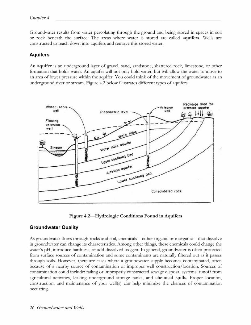
Groundwater results from water percolating through the ground and being stored in spaces in soil or rock beneath the surface. The areas where water is stored are called aquifers. Wells are constructed to reach down into aquifers and remove this stored water. Aquifers An aquifer is an underground layer of gravel, sand, sandstone, shattered rock, limestone, or other formation that holds water. An aquifer will not only hold water, but will allow the water to move to an area of lower pressure within the aquifer. You could think of the movement of groundwater as an underground river or stream. Figure 4.2 below illustrates different types of aquifers.
Figure 4.2—Hydrologic Conditions Found in Aquifers Groundwater Quality As groundwater flows through rocks and soil, chemicals – either organic or inorganic – that dissolve in groundwater can change its characteristics. Among other things, these chemicals could change the water’s pH, introduce hardness, or add dissolved oxygen. In general, groundwater is often protected from surface sources of contamination and some contaminants are naturally filtered out as it passes through soils. However, there are cases where a groundwater supply becomes contaminated, often because of a nearby source of contamination or improper well construction/location. Sources of contamination could include: failing or improperly constructed sewage disposal systems, runoff from agricultural activities, leaking underground storage tanks, and chemical spills. Proper location, construction, and maintenance of your well(s) can help minimize the chances of contamination occurring.
26 Groundwater and Wells

_____________________________________________________________________ Chapter 4
Groundwater Quantity The amount of water supplied by a drinking water well depends on the geological materials supplying the water. Wells that are identical in construction (e.g. four inch casing with a final well depth of 100 feet) may have very different well yields due to the geology supplying the water. Some areas of Minnesota, such as central Minnesota, have very abundant supplies of groundwater while other areas in Minnesota, such as some portions of southwestern Minnesota, have a harder time finding abundant supplies of groundwater. Wells Isolation Distances The quality of water produced by a well depends on where the well is constructed and how it is constructed. Before a new well is drilled, it is important to survey the entire property for the best location for the new well. All new wells must meet “isolation distances” specified in Minnesota Rules, Chapter 4725 (The Well Code). “Isolation distances” are the minimum physical separation that must exist between a well and a potential source of contamination (such as a septic system). The isolation distances are based on the ability of soil and bedrock to remove certain types of contaminants from the groundwater before they reach the well. Some common isolation distances are shown in Figure 4.3 on page 28. A complete list of the isolation distances used in Minnesota can be found in Appendix A. Failure to observe isolation distances may contribute to contamination of the well and is considered a violation of the Minnesota Well Code. For questions relating to isolation distances or about your drinking water well, refer to Appendix C for a list of MDH Well Management Contact Persons. Also see “Source Water Protection” in Chapter 2 for more information on isolation distances and protecting wells from contamination.
Groundwater and Wells 27

Chapter 4 ___________________________________________________________________
1 If safeguards are provided the minimum distance may be shortened. Consult Minnesota Rules, Chapter 4725. 2 A water-supply well which has less than 50 feet of watertight casing or which is not cased through a confining layer, such as a clay layer, at least 10 feet thick, must be located at least twice the indicated distance from the potential contaminant source. 3 A well between 5 and 10 feet of an electric transmission line, gas pipe, or LP tank must be placarded and work must not be performed on the well unless the line is de-energized and grounded or shielded, and the gas pipe or LP tank does not contain flammable gas. 4 The 20-foot distance applies to only irrigation wells and chemigation tanks protected with safeguards meeting the requirements of the Minnesota Department of Agriculture.
Figure 4.3—Selected "Isolation" or Separation Distances
* Community public water supply wells must have a minimum distance of 50 feet from any contamination source. See Appendix A for additional isolation distances for community public water supply wells.
28 Groundwater and Wells

_____________________________________________________________________ Chapter 4
Well Construction Drilled wells are the most common type of construction for new wells. They involve drilling a hole, installing steel or plastic casing and grouting around the casing to prevent entry of contaminants into the groundwater. Figure 4.4 illustrates a drilled well. A properly constructed drilled well provides good protection of the water supply source. Other methods of constructing wells such as dug, driven, augered, and bored are used in Minnesota; however, the vast majority of wells at nontransient noncommunity and nonmunicipal community water systems are drilled.
Figure 4.4—Drilled Well MDH Photo
Figure 4.5—Well Located in a Pit
ell Log
hen a new well is drilled, the well driller will complete a “well log” (also called a “well record”) and
Poor construction methods may allow contamination of both the well itself and the aquifer. An example of poor well construction is a well located in a pit as illustrated in Figure 4.5. The well pit may become flooded and cause contamination of the well. Additionally, wells in pits are safety hazards because the pit is a “confined space” that may develop a lack of oxygen or an accumulation of toxic gases. A confined space is a vessel that a human being does not normally occupy. The activities of the human being are inhibited due to the small work area. Entry into such a pit for maintenance and repair without proper equipment and authorization may result in injury or death.
MDH Photo W Wprovide a copy to the well owner and MDH. The well log contains important information about your well. It includes such information as the unique well number, well location, property owner’s name, the depth of the well and the type of geological materials the well was drilled through, drilling method, contamination sources near the well, well contractor certification, and other important information related to the well. The well log should be filed with your water records. An example of a well log is located in Appendix L.
Groundwater and Wells 29

Chapter 4 ___________________________________________________________________
Well Components
igure 4.6 illustrates above ground and below ground well components. These components are
Fdescribed in detail on the following pages.
Figure 4.6—Well and Water System
30 Groundwater and Wells
_____________________________________________________________________ Chapter 4
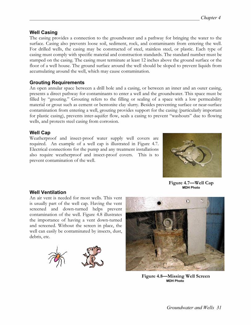
Well Casing The casing provides a connection to the groundwater and a pathway for bringing the water to the surface. Casing also prevents loose soil, sediment, rock, and contaminants from entering the well. For drilled wells, the casing may be constructed of steel, stainless steel, or plastic. Each type of casing must comply with specific material and construction standards. The standard number must be stamped on the casing. The casing must terminate at least 12 inches above the ground surface or the floor of a well house. The ground surface around the well should be sloped to prevent liquids from accumulating around the well, which may cause contamination. Grouting Requirements An open annular space between a drill hole and a casing, or between an inner and an outer casing, presents a direct pathway for contaminants to enter a well and the groundwater. This space must be filled by “grouting.” Grouting refers to the filling or sealing of a space with a low permeability material or grout such as cement or bentonite clay slurry. Besides preventing surface or near-surface contamination from entering a well, grouting provides support for the casing (particularly important for plastic casing), prevents inter-aquifer flow, seals a casing to prevent “washouts” due to flowing wells, and protects steel casing from corrosion. Well Cap Weatherproof and insect-proof water supply well covers are required. An example of a well cap is illustrated in Figure 4.7. Electrical connections for the pump and any treatment installations also require weatherproof and insect-proof covers. This is to prevent contamination of the well. Figure 4.7—Well Cap MDH Photo Well Ventilation An air vent is needed for most wells. This vent is usually part of the well cap. Having the vent screened and down-turned helps prevent contamination of the well. Figure 4.8 illustrates the importance of having a vent down-turned and screened. Without the screen in place, the well can easily be contaminated by insects, dust, debris, etc. Figure 4.8—Missing Well Screen MDH Photo
Groundwater and Wells 31
Chapter 4 ___________________________________________________________________
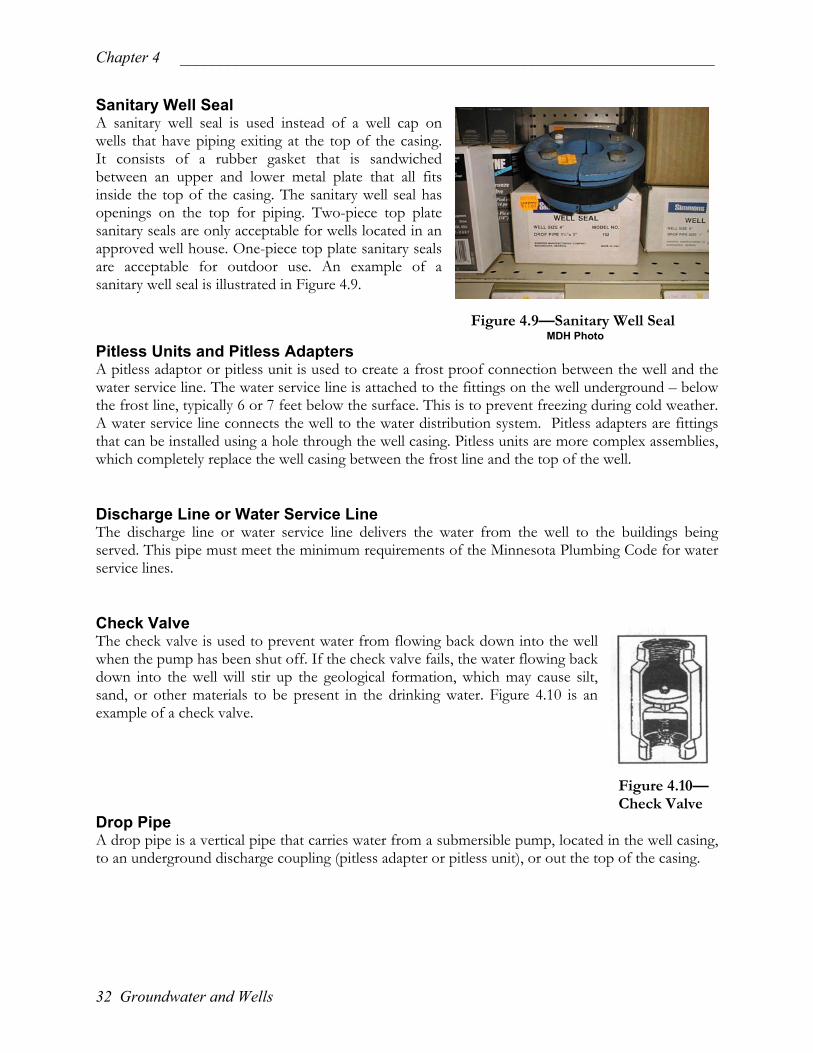
Sanitary Well Seal A sanitary well seal is used instead of a well cap on wells that have piping exiting at the top of the casing. It consists of a rubber gasket that is sandwiched between an upper and lower metal plate that all fits inside the top of the casing. The sanitary well seal has openings on the top for piping. Two-piece top plate sanitary seals are only acceptable for wells located in an approved well house. One-piece top plate sanitary seals are acceptable for outdoor use. An example of a sanitary well seal is illustrated in Figure 4.9. Figure 4.9—Sanitary Well Seal MDH Photo Pitless Units and Pitless Adapters A pitless adaptor or pitless unit is used to create a frost proof connection between the well and the water service line. The water service line is attached to the fittings on the well underground – below the frost line, typically 6 or 7 feet below the surface. This is to prevent freezing during cold weather. A water service line connects the well to the water distribution system. Pitless adapters are fittings that can be installed using a hole through the well casing. Pitless units are more complex assemblies, which completely replace the well casing between the frost line and the top of the well. Discharge Line or Water Service Line The discharge line or water service line delivers the water from the well to the buildings being served. This pipe must meet the minimum requirements of the Minnesota Plumbing Code for water service lines. Check Valve The check valve is used to prevent water from flowing back down into the well when the pump has been shut off. If the check valve fails, the water flowing back down into the well will stir up the geological formation, which may cause silt, sand, or other materials to be present in the drinking water. Figure 4.10 is an example of a check valve. Figure 4.10— Check Valve Drop Pipe A drop pipe is a vertical pipe that carries water from a submersible pump, located in the well casing, to an underground discharge coupling (pitless adapter or pitless unit), or out the top of the casing.
32 Groundwater and Wells

_____________________________________________________________________ Chapter 4
Pumps • Submersible Pump – Designed to operate completely submerged under water in the well
casing. It does not require a pump house or other interior space set aside for the pump. Figure 4.11 is an example of a submersible well pump.
Figure 4.11—Submersible Pump Figure 4.12—Jet Pump Being Removed From a Well MDH Photo MDH Photo • Jet Pump – A jet pump may be located on top of the well casing – or it may be offset from
the well in a pump house, and connected to the well with piping. Jet pumps operate by forcing water through a jet or venturi, which creates a partial vacuum (suction) and draws water from the well into the pumping system. Figure 4.12 is an example of a jet pump.
• Vertical Turbine Pump – These pumps are used for large volumes of water production such as community or industrial use. They have a motor, which is placed on top of the well and a turbine shaft extending below the water level. Figure 4.13 is an example of a vertical turbine pump.
Figure 4.13—Vertical Figure 4.14—Hand Pump Turbine Pump MDH Photo USEPA Photo
Hand Pump – A hand pump consists of a cylinder on a pump rod, which moves up and down and forces water to the surface. These are commonly found in parks and other recreational settings. Figure 4.14 is an example of a hand pump.
Groundwater and Wells 33

Chapter 4 ___________________________________________________________________
Well Screen The purpose of the well screen is to prevent sediment from entering the well while allowing water to enter the well. Raw Water Sample Tap A raw water sample tap allows for collection of water samples prior to any treatment. Well Casing Protection If a well is located in an area where it may be subject to damage by a vehicle, it is recommended that three posts be spaced evenly around the well as illustrated in Figure 4.15. This will provide protection for the well, while allowing access to the well for any work or repairs that need to be made. Figure 4.15—Well Casing Protection MDH Photo
Well Maintenance Permits Well maintenance permits are required for wells that are not sealed (see below), are not in use, or are inoperable. A well maintenance permit application must be submitted to MDH. These permits are valid for one year from the date issued and includes a yearly fee. Sealing Unused Wells Unused or abandoned wells that have not been properly sealed can provide a direct pathway for contaminants to enter the groundwater. Contaminants from surface water, runoff, or septic system drain fields, can enter the well through casings that have deteriorated or around casings that are not properly grouted. Unused wells also pose a safety hazard, especially for children, pets, and livestock. It is illegal to dispose of wastes in an unused well. According to Minnesota law, a well must be sealed in any of the following situations:
1) the well is contaminated and cannot be corrected; 2) the well has been improperly sealed in the past; 3) the well poses a threat to the health or safety of the public or
to groundwater quality; or 4) the well is not in use and does not have a maintenance permit.
A water well is properly sealed when it is removed from service and is completely filled with an MDH approved material. Only a licensed well contractor or a licensed well sealing contractor may seal a well. The contractor must seal the well in accordance with Minnesota law. An example of a well sealing log is available in Appendix M.
34 Groundwater and Wells

_____________________________________________________________________ Chapter 5
Chapter 5 Storage and Pressure Tanks Introduction Storage tanks can serve the following two purposes:
1) provide storage volume so the well pump does not have to operate for every water use; and
2) provide pressure to the distribution system.
A particular tank can serve one or both purposes depending on its location within the system and its type of configuration. The sizing of a water storage tank depends upon the function it provides. Other factors, such as cost, also play an important role in determining the size of a potable water storage tank. Any interior tank coatings must be NSF approved for potable water contact. Types of Storage Vessels There are a variety of tank types or configurations. The major types are hydropneumatic, diaphragm/bladder, elevated storage, and ground storage tanks. Pressure Tanks
• Hydropneumatic Pressure Tanks
These tanks are used to provide pressure to very small public water systems such as resorts, mobile home parks and very small communities. Hydropneumatic tanks operate using a pressure-rated tank containing approximately two-thirds water and one-third air at full capacity. These tanks do not have a barrier separating the air and water in the tank. They are not a good storage vessel for fire protection purposes due to the small volume of water within the vessel. Hydropneumatic tanks may be large-scale tanks that can be opened and accessed for cleaning and repair as illustrated in Figure 5.1 on page 36. Keep in mind that entering these large-scale pressure tanks presents safety hazards as the tanks are considered confined spaces. Entry into these tanks for maintenance and repair without proper equipment and authorization may result in death. Hydropneumatic tanks may be sealed (similar to the “household” type tank) in which the inside of the tank is inaccessible.
Storage and Pressure Tanks 35

Chapter 5 ___________________________________________________________________
Figure 5.1—Pneumatic Steel Pressure Tank Hydropneumatic pressure tanks may be buried. These tanks must be installed above the water table. The pressure gauge for a buried tank will typically be located alongside the well casing. Figure 5.2 illustrates a buried hydropneumatic pressure tank.
Figure 5.2—Buried Hydropneumatic Pressure Tank
36 Storage and Pressure Tanks

_____________________________________________________________________ Chapter 5
• Diaphragm/Bladder Pressure Tanks
Another type of pressure tank uses a “diaphragm/bladder” as a flexible separator between the air and water in the tank. The diaphragm/bladder prevents loss of air to the water thus eliminating the need for an air compressor. These are typically smaller tanks found in homes or small businesses. An example of a diaphragm/bladder pressure tank is illustrated in Figure 5.3.
Figure 5.3— Diaphragm/ Bladder Pressure Tanks USEPA Photo
Routine Maintenance for Pressure Tanks Routine maintenance includes observing the pressure gauges within the system. Large-scale pressure tanks should have a sight glass that will allow you to have direct observation of the air to water ratio. If accessible, it is important to clean the interior of the tanks annually for health and maintenance reasons. It is important to remember that the large-scale pressure tanks are a safety hazard as they are considered a confined space. Entry into such a tank without the proper equipment and authorization may result in death. Reducing the moisture in the hydropneumatic storage tank room, and painting the tank annually will help reduce the amount of external corrosion to large-scale tanks. It is a good idea to have a faucet placed near the pressure tank for flushing the tank and collecting water samples for testing. Tanks that lose their air pressure become waterlogged and must be repaired or replaced. Hydropneumatic and diaphragm/bladder pressure tanks must be housed in a heated building to prevent freezing of the tank and associated piping, air compressor, and controls. These tanks should never be operated above the pressure rating of the tank shown on the manufacturer’s plate. The pressure blow-off valve should be checked frequently for proper operation. This tank, if accessible, requires regular cleaning and inspection of the interior.
Storage and Pressure Tanks 37

Chapter 5 ___________________________________________________________________
Elevated Storage Tanks
• Elevated Storage tanks often have a large volume of storage and provide needed pressure for the system. Below are some examples of types of elevated storage.
Figure 5.4—Standpipe
MRWA Photo Figure 5.5—Leg Supported Tank Figure 5.6—Single Pedestal Tank MRWA Photo MRWA Photo
38 Storage and Pressure Tanks

_____________________________________________________________________ Chapter 5
Ground Storage Tanks Ground storage tanks can be installed either below or above ground. Figure 5.7 is an example of an above ground storage tank. They generally have the function of providing large volumes of reserve storage for peak-day demand. Ground storage tanks are easy to operate, as they are readily accessible for observations. Ground storage tanks should be kept full to avoid stagnant water and ensure minimal ice formation.
Figure 5.7—Ground Storage Tank MRWA Photo
Storage and Pressure Tanks 39

Chapter 5 ___________________________________________________________________
40 Storage and Pressure Tanks

_____________________________________________________________________ Chapter 6
Chapter 6 Treatment
We are fortunate in Minnesota to have an abundant supply of groundwater that, for the most part, requires no additional treatment to meet federal drinking water standards. However, sometimes treatment of groundwater is required to remove contaminants (such as nitrate) that pose a health risk; or to improve the water’s aesthetic characteristics (for example hardness or iron content). It is important to follow the manufacturer’s recommendations carefully in maintaining all treatment devices. Water Softening
Most water softening at small systems is accomplished with an ion exchange unit (water softener) that removes hardness from water. Water softeners are typically installed to treat all or much of the water supply in a building. An example of a water softener is illustrated in Figure 6.1. Dissolved calcium and magnesium cause hardness in water. An ion exchange unit uses a resin that exchanges sodium ions for calcium and magnesium ions as the water passes through. A brine (salt) tank provides the ion exchange unit the sodium required to regenerate the resin bed on a periodic basis. Periodic backwashing of the resin is required to remove solids that have become attached. Regeneration and backwashing are usually done automatically with a meter or time clock control. This can be adjusted if needed or desired because of changes in water use, or for improved efficiency or effectiveness. This backwash water must be disposed in an approved manner. The backwash line must discharge to a waste receptacle through an air gap. In the event that back-siphonage occurs during backwashing, an air gap will prevent contaminated water from being drawn into the water softener. Chapter 8 discusses proper backflow prevention techniques, including water softener discharge lines. Figure 6.1— Water Softener Internet Photo
Treatment 41

Chapter 6 ___________________________________________________________________
The brine tank must have salt in it at all times. If the tank is allowed to sit empty, bacteria may grow inside the brine tank and contaminate the water supply. Figure 6.2 is an example of a poorly maintained brine tank. It is recommended to disinfect the brine tank with a weak chlorine bleach solution at least once a year. If you purchase salt bags, it is important to keep the bags stored up off the floor to prevent contamination of the salt prior to being used in the water softener.
Figure 6.2—Dirty Brine Tank MDH Photo
Be aware that the softener brine tank is an opening to the environment and a location where contaminants can enter the system. Be sure the brine tank has
a tight fitting overlapping cover in place at all times except during servicing of the unit. Reverse Osmosis Reverse osmosis devices use a membrane with pores tiny enough to screen out inorganic chemicals. This system uses pressure to force the water through the membrane. It produces a water stream of treated water and a waste stream that contains the removed contaminants in a concentrated form. Reverse osmosis systems are often installed to treat a single fixture or point of use. Figure 6.3 illustrates the components of a reverse osmosis treatment device.
Figure 6.3—Reverse Osmosis Device Internet Photo
Reverse osmosis can be used to remove nitrates, arsenic, and other inorganics or dissolved solids. Very hard water may need to have softening before the reverse osmosis treatment to extend the life of the membrane. One operating problem associated with a reverse osmosis system is that the membrane eventually becomes plugged with contaminants and thus reduces the efficiency of the membrane. Proper maintenance is critical to the use of a reverse osmosis device.
42 Treatment

_____________________________________________________________________ Chapter 6
Activated Carbon Carbon material in these devices reduces organic chemicals, such as those that can cause offensive tastes and odors. Activated carbon filters may be installed either to treat an entire system or just a single point of use. Figure 6.4 is an example of an activated carbon filter. Such units can enhance bacterial growth by providing nutrients. Carbon filters have a limited capacity, so frequent replacement of the filter media or cartridge is necessary.
Figure 6.4—Activated Carbon Filter MRWA Photo
Sediment or Particulate Filters Filters trap particles in a porous material while allowing water to pass through. They are often used as prefilters ahead of other treatment. They can reduce particles like sand and rust but cannot remove anything dissolved in the water. Sediment or particulate filters are often installed to treat the entire water system. Figure 6.5 is an example of a sediment/particulate filter. These filters, like activated carbon filters, require routine maintenance to prevent bacterial growth. Figure 6.5—Sediment/ Particulate Filter MRWA Photo
Other Treatment Devices
There are other treatment devices available such as anion exchange, iron filters, and distillation that are used to remove contaminants from drinking water. For more information on other treatment devices, contact the Minnesota Department of Health, Drinking Water Protection Section at 651/215-0770.
Treatment 43

Chapter 6 ___________________________________________________________________
44 Treatment
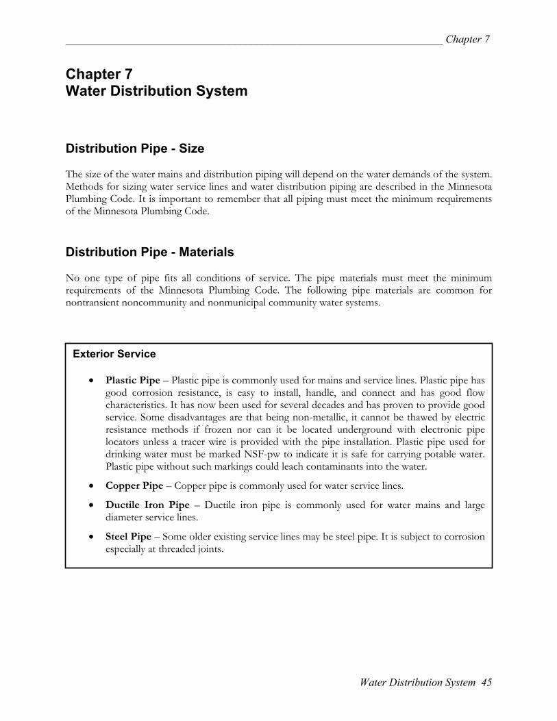
_____________________________________________________________________ Chapter 7
Chapter 7 Water Distribution System Distribution Pipe - Size The size of the water mains and distribution piping will depend on the water demands of the system. Methods for sizing water service lines and water distribution piping are described in the Minnesota Plumbing Code. It is important to remember that all piping must meet the minimum requirements of the Minnesota Plumbing Code. Distribution Pipe - Materials No one type of pipe fits all conditions of service. The pipe materials must meet the minimum requirements of the Minnesota Plumbing Code. The following pipe materials are common for nontransient noncommunity and nonmunicipal community water systems.
Exterior Service
• Plastic Pipe – Plastic pipe is commonly used for mains and service lines. Plastic pipe hasgood corrosion resistance, is easy to install, handle, and connect and has good flowcharacteristics. It has now been used for several decades and has proven to provide goodservice. Some disadvantages are that being non-metallic, it cannot be thawed by electricresistance methods if frozen nor can it be located underground with electronic pipelocators unless a tracer wire is provided with the pipe installation. Plastic pipe used fordrinking water must be marked NSF-pw to indicate it is safe for carrying potable water.Plastic pipe without such markings could leach contaminants into the water.
• Copper Pipe – Copper pipe is commonly used for water service lines.
• Ductile Iron Pipe – Ductile iron pipe is commonly used for water mains and largediameter service lines.
• Steel Pipe – Some older existing service lines may be steel pipe. It is subject to corrosionespecially at threaded joints.
Water Distribution System 45

Chapter 7 ___________________________________________________________________
Interior Distribution Water distribution piping in buildings is usually copper or plastic but some old piping may begalvanized steel.
• Copper Pipe - Since 1985, copper must be jointed with lead free solder. It is importantto remember that all interior distribution piping must meet the minimum standards of theMinnesota Plumbing Code.
• Plastic Pipe - Plastic pipe used for drinking water must be marked NSF-pw to indicate itis safe for carrying potable water. Plastic pipe without such markings could leachcontaminants into the water. The only plastic pipe materials currently listed in theplumbing code are:
o Chlorinated Polyvinyl Chloride (CPVC) – Rigid material usually cream colored.
o Polybutylene (PB) – Flexible material usually gray colored.
o Cross Link Polyethylene (PEX) – Could also be accepted on a case-by-case basisby the administrative authority as an alternate material.
NOTE: Polyethylene pipe (flexible black pipe) is not approved for use in buildings.
Valves Many types of valves may be used in the water supply, but all have basically the same function – to control or to stop the flow in pipes. Valves should be installed at enough points on a water system so branches and fixtures can be isolated during repairs. Valves should also be installed so there is minimal loss of water service during repairs. It is important to exercise valves on a regular basis to ensure that they will work properly when needed. The plumbing code requires valves in some applications to have a full pipe size (full-port) waterway. Common types of valves are:
• Gate Valves – A common type of valve used in the water distribution system is the gate valve. This valve is reasonably dependable and has an almost unobstructed waterway when open. Figure 7.1 is an example of a gate valve.
Figure 7.1— Gate Valve
46 Water System Distribution

_____________________________________________________________________ Chapter 7
• Ball Valves – Ball valves are used as shut-off valves and throttling valves and provides positive shut-off, and quick closing with ¼ turn of the handle. Some provide a full pipe size waterway; some do not. Figure 7.2 is an example of a ball valve.
Figure 7.2—Ball Valve MDH Photo • Globe Valves – Except for some special service applications, the globe valves used in water
systems are generally three inches or smaller. The high-pressure loss in this valve limits it to smaller sizes. Globe valves are used frequently for throttling and control applications at equipment or fixtures. Figure 7.3 is an example of a globe valve.
Figure 7.3—Globe Valve
Water Distribution System 47

Chapter 7 ___________________________________________________________________
48 Water System Distribution

_____________________________________________________________________ Chapter 8
Chapter 8 Cross Connections and Backflow Prevention Definitions Cross Connections – A cross connection is a direct connection of a potable water source with any system, equipment or fixture which contains nonpotable water. Cross connections can affect water quality and create health problems due to contamination. Backflow as a result of a cross connection can cause serious illness and even death. Backflow – Backflow is defined as undesired, reversed flow in a piping system. Backflow can be caused by back-siphonage, backpressure, or a combination of the two.
Back-siphonage backflow occurs when there is a partial vacuum (negative pressures) in a water-supply system, potentially drawing contaminants into a potable water supply. The effect is similar to sipping a soda by inhaling through a straw.
Backpressure backflow occurs when the pressure of the nonpotable system exceeds the positive pressure in the potable water distribution lines.
Control of Cross Connections Water supplies must be protected against contamination from equipment and other water using systems. A water system should develop a sound program that eliminates health hazards caused by cross connections. Backflow prevention devices are used to protect the water supply from contamination. Often, a simple air gap or backflow prevention device can prevent hazards. Air gaps are the best measure to use when there is potential for a cross connection to an extreme hazard. The Minnesota Plumbing Code (Minnesota Rules 4715.2100) specifies the applications for various backflow prevention devices. See Appendix N for a list of these applications. Key Points in Cross Connection Control Are:
Elimination or protection of direct connections between potable and nonpotable systems.
Design of piping systems in the potable water distribution system so that enough water at the desired pressure is always available.
Maintaining the distribution system to minimize breaks and preventing any new connections to equipment or systems that could allow the entry of contaminants unless a proper backflow prevention device is provided.
Maintain all backflow preventers in good working order.
Be alert when servicing the system, of the potential for contamination due to cross connections to plumbing fixtures, equipment, or other systems.
Cross Connections and Backflow Prevention 49

Chapter 8 ___________________________________________________________________
Examples of Common Cross Connections The following examples illustrate cross connections:
1. A common cross connection is illustrated by a hose connected to a sillcock with the other end of the hose lying in a pool or sink full of polluted or contaminated water. An example of this type of cross connection is illustrated in Figure 8.1. In this case backflow occurs by back-siphonage. If a partial vacuum is set up in the water distribution system due to heavy demand, a pipe break, or system servicing, water can be drawn from the sink by suction when the faucet is opened.
Figure 8.1—Hose in Polluted Water Cross Connection
This type of cross connection can be corrected by providing an Atmospheric Vacuum Breaker (AVB) on the hose bibb.
2. A cross connection to a lawn sprinkler system can cause back-siphonage when a partial
vacuum in the water system draws water from pooled water near a sprinkler head. Backflow caused by backpressure can occur when the sprinkler head is at a higher elevation than the connection to the potable water system. An example of this type of cross connection is illustrated in Figure 8.2. Herbicides, pesticides, other chemicals, and microorganisms can be drawn in through sprinkler openings.
Figure 8.2—Lawn Sprinkler Cross Connection
This type of cross connection can be corrected by providing an AVB or a Pressure Vacuum Breaker (PVB), depending on system conditions.
50 Cross Connections and Backflow Prevention

_____________________________________________________________________ Chapter 8
3. When a cross connection to a plumbing drainage
system exists, backflow can occur. A partial vacuum in the potable water line can draw contaminated water from the drainpipe. An example of this would be the drain line from a water softener being connected to a plumbing drainage line, or discharge to a floor drain without an air gap in the discharge line. Figure 8.3 illustrates this type of cross connection.
Figure 8.3—Plumbing Drainage System Cross Connection
This type of cross connection can be corrected by providing an air gap between the discharge line and the floor drain.
4. Cross connections to a pressurized system, such as a hot water boiler, are not uncommon. In
this case backflow can occur by backpressure and by back-siphonage. Backpressure backflow can occur when the water pressure in the boiler or pressurized tank is greater than the pressure in the water distribution lines. Figure 8.4 illustrates this type of cross connection.
Figure 8.4—Boiler Cross Connection
This type of cross connection can be corrected by providing a Reduced Pressure Backflow Prevention Assembly (RPZ).
5. Reverse osmosis treatment devices need an air gap in the concentrate water line before
discharge to waste. A partial vacuum in the potable water line can draw contaminated water from the drainpipe, which could contaminate the treatment device. This can be provided in an air gap faucet (see Figure 6.3 on page 42) designed specifically for this purpose.
Cross Connections and Backflow Prevention 51

Chapter 8 ___________________________________________________________________
Backflow Prevention There are several basic ways to prevent or reduce the possibility of backflow in cross connections: air gaps, atmospheric vacuum breakers, hose bibb vacuum breakers, pressure-type vacuum breaker assemblies, double check valve assemblies, dual-check valve with intermediate atmospheric vent, and reduced-pressure backflow prevention assemblies.
• Air gap – An air gap—physical separation of the potable and nonpotable systems by an air space—is the most reliable backflow prevention measure. The vertical distance between the supply pipe and the flood-level rim should be two times the diameter of the supply pipe, but never less than one inch. An air gap can be used in situations where potable water runs into a tank, drain, or pipe which is under atmospheric pressure. This type of backflow prevention method cannot be used for a direct connection to a pressurized system. An example of an air gap is illustrated in Figure 8.5.
Figure 8.5—Air Gap • Atmospheric Vacuum Breaker (AVB) – These devices only protect against back-siphonage,
not backpressure. They must be installed on the discharge side of the last control valve. They must be installed six inches above the rim of the fixture they serve. In addition, they cannot be used under continuous pressure for a period of eight hours or more. Atmospheric vacuum breakers are usually used with faucets where a hose could be attached. Atmospheric vacuum breakers cannot be tested once installed. Figure 8.6 is an example of one type of atmospheric vacuum breaker.
Figure 8.6—Atmospheric Vacuum Breaker
52 Cross Connections and Backflow Prevention

_____________________________________________________________________ Chapter 8
• Hose Bibb Vacuum Breaker (if AVB is not installed) – This device is used to protect primarily against back-siphonage at otherwise unprotected hose bibbs. Any new installation or new hose bibbs must use devices that meet ASSE Standard 1052. Figure 8.7 is an example of an ASSE Standard 1052 Hose Bibb Vacuum Breaker.
Figure 8.7—Hose Bibb Vacuum Breaker • Pressure Vacuum Breaker (PVB) – Pressure
vacuum breaker assemblies are similar to atmospheric vacuum breakers except that these devices can be used under continuous pressure. They cannot prevent backflow due to backpressure and must be installed above the usage point to prevent back-siphonage. They must be installed at least 12 inches above the rim of the device that they are protecting. Figure 8.8 is an example of a pressure vacuum breaker.
Figure 8.8—Pressure Vacuum Breaker
• Double Check Valve Assembly (DCVA) – These assemblies are used for a direct connection between two potable water systems and therefore have very limited application. They cannot be used to connect a potable water supply to a contaminated or high-hazard water system. The assembly, as shown in Figure 8.9, offers only a partial degree of protection because particles can prevent proper seating of the valves causing them to leak. Double-check valve assemblies protect against backpressure and back-siphonage conditions. Once installed, they can be tested.
Figure 8.9—Double Check Valve Assembly
Cross Connections and Backflow Prevention 53

Chapter 8 ___________________________________________________________________
• Dual-Check Valve with Intermediate Atmospheric Vent (DCVIAV) – This assembly is permitted for low or moderate hazard with small pipe sizes. The DCVIAV can be used to protect against backpressure and can be used under continuous pressure. An example of this type of backflow prevention device is illustrated in Figure 8.10 below.
Figure 8.10—Dual Check Valve with Intermediate Atmospheric Vent
• Reduced Pressure Zone Backflow
Prevention Assembly (RPZ) – This assembly provides protection against backpressure and back- siphonage. The RPZ can be used under continuous pressure and in high-hazard conditions. The RPZ is designed so it will operate even if both the check valves become fouled. A reduced-pressure backflow preventer, as shown in Figure 8.11, requires yearly testing by certified personnel and a rebuild every five years. Figure 8.11—Reduced Pressure Zone Backflow Prevention Assembly
Appendix N contains a list of the different types of backflow prevention devices required where an air gap cannot be provided.
Contact the MDH Plumbing Program at 651/215-0836 with any questions regarding backflow prevention or the installation of backflow prevention devices.
54 Cross Connections and Backflow Prevention

_____________________________________________________________________ Chapter 9
Chapter 9 Water System Security and Emergency Planning Water System Security
Security at water facilities is necessary to protect against emergencies, vandalism and other threats. Although it is unlikely that a nontransient noncommunity or nonmunicipal community water system in Minnesota would be the target of terrorism or sabotage, there are several common-sense steps you can take to even further reduce the chance of an incident at your water system. Securing the water system is a vital role of both the owner and operator.
Securing your water system must be considered a high priority. Having a secured facility may help prevent loss of water service in the event of an emergency. The steps you take will depend on the type and operation of your water system. All public water systems, including your water system, should take some time to review safety and security. The items listed below may help prevent vandalism and reduce potential safety hazards.
Routinely check the facility for any signs of tampering. Items to check include wells, well houses, plumbing, treatment rooms, storage rooms, and the water facility grounds. It is recommended to check the facilities on a daily basis, which will allow you to quickly find any problem that has come up since the last check.
Provide locks on all well house doors. Provide locking well caps.
Prevent access to other water systems components – such as tanks, towers, treatment equipment, and chemical storage – as much as possible. Limit public access to water system components. Deter entry to these areas with signs labeled “Employees Only” or “Restricted Access.” Consult with your local fire department about acceptable ways to lock doors, gates, and windows.
Be on the lookout for any suspicious activities or unknown persons around the water system. If a person is unknown, do not hesitate to ask for identification.
Provide adequate lighting around the entire facility.
If you use water treatment chemicals, make sure that containers purchased or delivered are intact and secure. Use only reliable sources and known contractors. It is a good idea to have a list of contractors and vendors that you may use. Do not accept deliveries from unknown individuals or vendors. It is advisable to have a staff person present during all deliveries.
If your water supply is run using a computer system, make sure that system is secure and be on the alert for attempts to disrupt its operation. Also, secure all maps, records, and any other information that is vital to the operation of the water system.
Water System Security and Emergency Planning 55

Chapter 9 ___________________________________________________________________
Water System Security and Emergency Planning 56
If you hire someone from a vendor to work on the water system (plumber, well contractor, etc.) verify that any individuals coming to your facility are employed by that vendor before allowing him or her to do any work.
Introduce yourself to local law enforcement to review your security measures and to establish a personal contact (name and phone number).
Provide an emergency plan for your facility.
Emergency Planning It is important to be prepared for any type of emergency situation that may occur at your water system. Being prepared will save time, money, and frustration. Your emergency plan may become vital in the event of a disaster in which you lose your capability of supplying water to your system. Items to be included in the emergency plan include:
a. a summary of your drinking water system; b. a list of contacts with phone numbers; and c. a description of alternative water supply options.
It is important to have the water system information and contacts with phone numbers documented for everyone to use. You may know the information but if you aren’t at the facility, will others know whom to contact in an emergency? Once the lists are completed, it is best to post a copy in a central location and provide copies in all well houses. It is important to update these lists on an annual basis. Appendix O has some examples of charts that you can use for your emergency plan. Responding to Suspicious Situations
If you suspect that your water system has been tampered with or you observe suspicious activity, contact your local law enforcement immediately. If local law enforcement is unavailable, you can report suspicious activity or threat to the Minnesota Duty Officer at 651/649-5451 (metro) or 800/422-0798 (statewide). Do not enter a suspicious situation
as your health and safety may be compromised. If you suspect possible tampering with or contamination of your water supply, do not allow the water to be used for drinking until local law enforcement has investigated and you have been told to resume use of the water supply. If you suspect that your system has possibly been tampered with or contaminated, please contact your MDH representative.