saf l baff le - upstreamtechnologies.usupstreamtechnologies.us/docs/safl-baffle-design-guide.pdf ·...
TRANSCRIPT

SAF L BAFF LE www.upstreamtechnologies.us600 County Road D West, Suite 14
New Brighton, MN 55112
651.237.5123
DESIGN GUIDE
Upstream Technologies 600 County Road D West, Suite 14 New Brighton, Minnesota 55112 651-237-5123
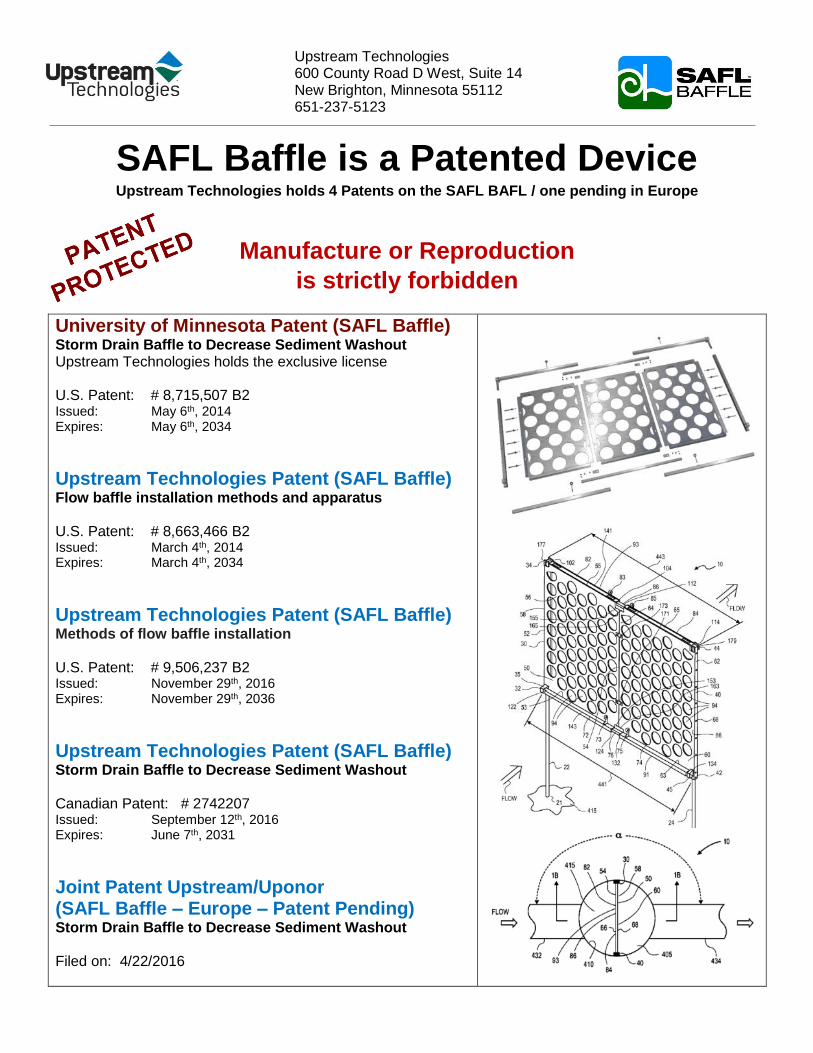
SAFL Baffle is a Patented Device Upstream Technologies holds 4 Patents on the SAFL BAFL / one pending in Europe
Manufacture or Reproduction
is strictly forbidden
University of Minnesota Patent (SAFL Baffle) Storm Drain Baffle to Decrease Sediment Washout Upstream Technologies holds the exclusive license U.S. Patent: # 8,715,507 B2 Issued: May 6th, 2014 Expires: May 6th, 2034
Upstream Technologies Patent (SAFL Baffle) Flow baffle installation methods and apparatus U.S. Patent: # 8,663,466 B2 Issued: March 4th, 2014 Expires: March 4th, 2034
Upstream Technologies Patent (SAFL Baffle) Methods of flow baffle installation U.S. Patent: # 9,506,237 B2 Issued: November 29th, 2016 Expires: November 29th, 2036
Upstream Technologies Patent (SAFL Baffle) Storm Drain Baffle to Decrease Sediment Washout Canadian Patent: # 2742207 Issued: September 12th, 2016 Expires: June 7th, 2031
Joint Patent Upstream/Uponor (SAFL Baffle – Europe – Patent Pending) Storm Drain Baffle to Decrease Sediment Washout Filed on: 4/22/2016

SAFL Baffle DESIGN GUIDEThis guide can be used to design a SAFL Baffle and a sump structure for stormwater sediment
removal. It will introduce you to some essential terminology, applications where the SAFL Baffle
is useful, and design process. If this guide is not clear, please give our engineering team a call
at 651.237.5123
Contents Essential Terminology: ............................................................................................................... 2
Applications: .............................................................................................................................. 2
Conceptual Design Flowchart .................................................................................................... 3
Final Design Flowchart ............................................................................................................... 4
Retrofit Criteria Chart ................................................................................................................. 5
Sediment Removal Charts ......................................................................................................... 6
SHSAM Instructions ................................................................................................................... 9
SHSAM Input Worksheet ........................................................................................................ 9
SHSAM Tutorial .....................................................................................................................10
Pipe Hydraulics Criteria .............................................................................................................13
Pipe Configuration .................................................................................................................13
Headloss ...............................................................................................................................15
SAFL Baffle Size Chart .............................................................................................................16
Standard Details .......................................................................................................................17
Specification .............................................................................................................................22
Maintenance & Monitoring ........................................................................................................27
Visual Inspection ...................................................................................................................27
Sump Cleaning ......................................................................................................................27
Nonstandard Designs................................................................................................................29
Sump Structures with less than 3-ft of depth..........................................................................29
Curb to sump structure ..........................................................................................................29

SAFL Baffle Design Guide | Upstream Technologies, Inc. Page 2
Essential Terminology: SAFL Baffle:
a perforated, stainless steel baffle
bolts vertically into a sump structure for improved sediment capture
Sump structures:
circular or rectangular structures
one or more inlet pipes
one outlet pipe
depth below the outlet pipe (sump)
Applications: The SAFL Baffle is a great choice for stormwater sediment removal in several situations:
Retrofits: You are looking to improve the performance of your existing storm sewerinfrastructure and have an existing sump structure that meets the criteria laid out in thisguide.
Pretreatment: You want to reduce maintenance of downstream BMPs like detentionponds, infiltration systems, and underground vaults.
Primary Treatment: There is no room for other BMPs, or your project is low on funds,but you want to do something about stormwater sediment.

Pretreatment
Other Use
Retrofit
Choose another location. Maintenance vehicles
must be able to access
the structure.
Contact Upstream
Technologies
NO
Select another site or explore building new
sump structures for SAFL
Baffles
Nearly all hydrodynamic
separator BMPs, including the SAFL Baffle, cannot capture
these particles. Non-separator BMPs are recommended.
Geographic location of
project
Site area
Select
structure size based on
Sediment Removal Chart
Select SAFL Baffle size with
SAFLBaffle
Size Chart
SAFL Baffle
Concetpual Design
Flowchart
Estimate cost at
http://upstreamtechnologies.us/price.shtml
End


SAFL Baffle Design Guide | Upstream Technologies, Inc. Page 5
Retrofit Criteria Chart Here are the criteria for selecting a sump structure that is a good candidate for a SAFL Baffle.
1. The structure can be round or box shaped2. Sump depth (Ys) equal or greater to 3-ft (contact us if you have something slightly shallower)3. The diameter or width (D) of the structure must be 3-ft, 4-ft, 5-ft, 6-ft, 7-ft, or 8-ft, 9-ft, or 10-ft.4. Greater than 75% of the drainage into the structure enters through an inlet pipe (or inlet
pipes), as opposed to an inlet grate5. The manhole casting inner diameter, (d), is 24-in in diameter or greater (27-in preferred). In
most cases, the SAFL Baffle can accommodate a casting with an inner diameter of18-in, but please call our engineering department for review (651.237.5123)
6. One outlet pipe7. The height of the SAFL Baffle, H, should be determined using the Size Chart8. The distance from the invert of the outlet pipe to the bottom of the SAFL Baffle, y, should be
1-ft9. Inlet pipes and outlet pipe meet Pipe Hydraulics Criteria later in guide

SAFL Baffle Design Guide | Upstream Technologies, Inc. Page 6
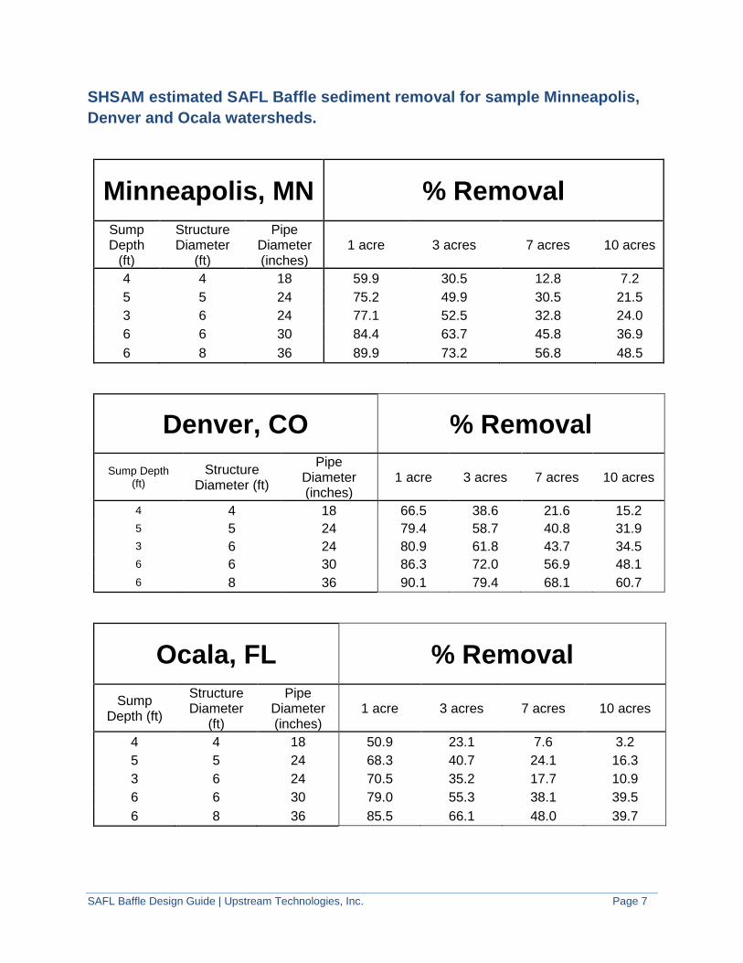
Sediment Removal Charts These six charts provide examples of sediment removal efficiency for various watershed sizes. Sediment removal efficiency is site specific, so final designs should utilize the SHSAM software to calculate it. Instructions are provided in the following section of this design guide, beginning on Page 9.
Here are the assumptions used to generate these charts with SHSAM:
Area (acres): 1, 3, 7, 10
Impervious (%): 70
Hydraulic Length (ft): 381, 660, 1008, 1205
Average Slope (%): 1.5
CN (pervious): 70
Weather Station Precipitation: Local, 15 minute
Water Temperature: Local, average daily
Washout Included?: Yes
Bypass?: No
Sediment Distribution: Janna-Omid
Janna-Omid Particle Size Distribution:
Particle Size (microns)
Percent Finer
Specific Gravity
1000 100 2.65 500 95 2.65 250 90 2.65 170 65 2.65 100 35 2.65 50 15 2.65 8 2 2.65 2 1 2.65
SAFL Baffle Design Guide | Upstream Technologies, Inc. Page 7
SHSAM estimated SAFL Baffle sediment removal for sample Minneapolis,
Denver and Ocala watersheds.
Minneapolis, MN % Removal
Sump Depth
(ft)
Structure Diameter
(ft)
Pipe Diameter (inches)
1 acre 3 acres 7 acres 10 acres
4 4 18 59.9 30.5 12.8 7.2
5 5 24 75.2 49.9 30.5 21.5
3 6 24 77.1 52.5 32.8 24.0
6 6 30 84.4 63.7 45.8 36.9
6 8 36 89.9 73.2 56.8 48.5
Denver, CO % Removal
Sump Depth (ft)
Structure Diameter (ft)
Pipe Diameter (inches)
1 acre 3 acres 7 acres 10 acres
4 4 18 66.5 38.6 21.6 15.2
5 5 24 79.4 58.7 40.8 31.9
3 6 24 80.9 61.8 43.7 34.5
6 6 30 86.3 72.0 56.9 48.1
6 8 36 90.1 79.4 68.1 60.7
Ocala, FL % Removal
Sump Depth (ft)
Structure Diameter
(ft)
Pipe Diameter (inches)
1 acre 3 acres 7 acres 10 acres
4 4 18 50.9 23.1 7.6 3.2
5 5 24 68.3 40.7 24.1 16.3
3 6 24 70.5 35.2 17.7 10.9
6 6 30 79.0 55.3 38.1 39.5
6 8 36 85.5 66.1 48.0 39.7

SAFL Baffle Design Guide | Upstream Technologies, Inc. Page 8
SHSAM estimated SAFL Baffle sediment removal for sample Seattle, Los
Angeles and Newark watersheds.
Seattle, WA % Removal Sump Depth
(ft)
Structure Diameter (ft)
Pipe Diameter (inches)
1 acre 3 acres 7 acres 10 acres
4 4 18 76.9 47.9 29.1 21.5
5 5 24 87.9 70.6 52.2 41.6
3 6 24 85.3 63.1 43.5 33.7
6 6 30 93.3 82.5 69.8 60.9
6 8 36 95.8 88.1 79.7 73.4
Los Angeles, CA % Removal Sump Depth
(ft) Structure
Diameter (ft) Pipe Diameter
(inches) 1 acre 3 acres 7 acres 10 acres
4 4 18 72.0 40.4 20.8 13.9 5 5 24 84.7 61.8 40.1 30.0 3 6 24 81.7 55.6 33.7 24.3 6 6 30 91.1 75.6 56.7 46.4 6 8 36 94.4 83.4 68.5 59.4
Newark, NJ % Removal Sump
Depth (ft)
Structure Diameter
(ft)
Pipe Diameter (inches)
1 acre 3 acres 7 acres 10 acres
4 4 18 73.3 50.3 31.1 22.1
5 5 24 83.7 65.4 47.7 38.8
3 6 24 81.0 60.2 41.3 32.3
6 6 30 89.3 75.5 59.8 51.7
6 8 36 92.5 82.1 68.6 61.0

SAFL Baffle Design Guide | Upstream Technologies, Inc. Page 9
SHSAM Instructions SHSAM is a free tool for sizing a sump structure and SAFL Baffle. Use the following SHSAM
Input Worksheet to organize your inputs required to run SHSAM. If not familiar with SHSAM,
skip the SHSAM Input Worksheet and follow the sample SHSAM Tutorial.
SHSAM Input Worksheet
Watershed Information Watershed Area acres Impervious Fraction % Hydraulic Length feet Average Slope % SCS Curve Number (pervious area) Hydraulics Bypass Y / N? if Y, @ cfs Sump Structure Diameter inches Sump Depth inches Inlet Pipe Diameter inches Outlet Pipe Diameter inches Rainfall Site Location Rainfall Data Set Location Analysis Period start end SHSAM has built in rainfall and temperature data for Chicago, IL; Dallas, TX; Denver, CO; Golden Valley, MN; Los Angeles, CA; Newark, NJ; Northfield, MN; Ocala, FL; Red Wing, MN; San Francisco, CA; Seattle, WA, St. Louis, MO; and Washington, DC. Sediment
Particle Size (microns) Percent Finer (%) Specific Gravity
Note: Verify with regulatory agency to determine sediment requirements If acceptable, use SHSAM’s built in sediment distributions SHSAM allows use of custom particle data.
Inflow TSS Concentration mg/l

SAFL Baffle Design Guide | Upstream Technologies, Inc. Page 10
SHSAM Tutorial
This section of the guide will help you run an example simulation in SHSAM for a watershed in
the Minneapolis, MN area. Undoubtedly your watershed is not in Minneapolis, MN, but the
principles remain the same. By selecting inputs that match your watershed, instead of the inputs
in this guide, you can create a SHSAM simulation that is reliable for your design decisions. If
SHSAM’s built in drop down menus do not provide inputs that match your watershed’s
conditions, follow SHSAM’s instructions for inputting custom data into the program.
For a more in-depth SHSAM tutorial, exploring SHSAM’s limitations and advanced features,
please watch our SHSAM tutorial series on our Design Guide:
(http://upstreamtechnologies.us/products/SAFL/shsam.shtml)
An example simulation:
1. Download SHSAM from https://www.barr.com/WhatsNew/SHSAM/SHSAMapp.asp
2. Install SHSAM and start the program.
3. Read the first tab titled 1. Introduction
4. Select the second tab, titled 2. Root Directory. Set a root directory where SHSAM output files
can be sent and input files can be placed. It is important to choose a file path that does not
include spaces. For example, "C:\Users\Kurt\SHSAMOutputs" is an acceptable file path, but
"C:\Users\Kurt\SHSAM Outputs" is not.
5. Select the third tab, titled 3. BMP. Select the radio button titled Standard Sumps with SAFL
Baffle. A pop up window will display, asking whether or not washout should be incorporated into
the calculations. Select Yes for washout, and select No for a bypass.
6. Next, select the fourth tab, titled 4. Weather Station Precipitation. From the top-most drop
down menu, select the Golden Valley weather station precipitation to be used for the estimate.
Each weather station collected data for many years. Select the range of dates that are deemed
appropriate for the estimate. For this example, use the data from 1995 to 2007. Author’s Note –
If SHSAM does not provide acceptable precipitation data for your region, free-to-download 15
minute precipitation data can be found at http://www.ncdc.noaa.gov/cdo-web/. Select
Precipitation Data, 15 minute and follow the subsequent instructions for download. For detailed
instructions on how to complete this process, watch our SHSAM video tutorial series.
7. Select the fifth tab, titled 5. Particle Size Distribution. Use the drop down menu to select the
particle size distribution to represent the influent sediment entering the sump. For this example,
choose MNDOT Road Sand. Author’s Note: Influent particle size distribution has a large effect
on the performance of stormwater BMPs. If a particle size distribution analysis is not available for
your site, I recommend performing several SHSAM simulations. Keep all watershed values
constant, but change the particle size distribution from Mn/DOT Road Sand, OK110, to NURP,
and compare how the removal efficiency of your BMP changes between simulations.
8. Click on tab six, titled 6. Watershed Data. Enter the drainage area, percent pervious, hydraulic
length, average slope, and curve number for the watershed. For this example, use an Area of 3

SAFL Baffle Design Guide | Upstream Technologies, Inc. Page 11
acres, an Impervious (%) of 85, a Hydraulic Length (ft) of 700, an Average Slope (%) of 2.5, and
a CN (pervious) of 70.
9. Next, select the seventh tab, titled 7. Temperature. Click No to use the drop down menu for
water temperature data. From the drop down menu, select the St. Paul 1991-2007 data. Author’s
Note – If SHSAM’s drop down temperature menu doesn’t provide a suitable daily water/air
temperature file, you can download this data at http://www.ncdc.noaa.gov/cdo-web/. View our
SHSAM video tutorial series for detailed description of how to do this.
10. For the final step of entering input parameters, select the eighth tab, titled 8. Influent
Concentration / Count Sump Cleanings. Enter the influent concentration of sediment reaching
the sump to be 200 mg/L. Author’s Note – if you have data about the concentration of sediment
found in stormwater leaving your watershed, use that value for this input. However, if you do not
have data, I recommend running several simulations where sediment influent concentration is
varied. The removal efficiency of your device will not change as sediment influent concentration
is increased, but the total poundage of sediment captured will change (and in turn, maintenance
frequency).
11. Press the button in the bottom right hand corner called Run Model.
12. Select Tools---Output Data from the File Menu. Select the tab titled Summary. Scroll to the
bottom of the Summary window to find a smaller “Summary” table. This table (consisting of 8
rows) summarizes the sediment capture data for various sized sump manholes equipped with a
SAFL Baffle. Author’s Note – When performing a simulation with other BMPs, the number of
rows making up the “Summary” table will vary.
13. Within this smaller summary table, the column titled Model displays the different sump manhole
sizes used for the simulation. 42 = 4-ft diameter by 2-ft deep sump manhole, 44 = 4-ft diameter
by 4-ft deep sump manhole, etc.
14. The column titled Total Load shows the amount of sediment that traveled off of the simulated
drainage area and ended up traveling into the sump manhole.
15. The column titled Total Load Removed shows the amount of sediment that the sump manhole
equipped with a SAFL Baffle actually captured.
16. The column titled Removal Efficiency is the percentage of sediment that was captured in the
sump manhole equipped with a SAFL Baffle with respect to the total amount of sediment that
traveled into the system.
17. The next three columns display the dimensions of the sump manholes that were used for the
simulation.
18. To compare the performance of the SAFL Baffle installed in a sump manhole to another device, I
recommend copying and pasting the small “Summary” table into a spreadsheet program like
Excel.
19. Next, exit out of the Output window. The Input Data window should still be up. Click on the third
tab, titled 3. BMP. Select a different device. A pop up window will display, asking whether or not

SAFL Baffle Design Guide | Upstream Technologies, Inc. Page 12
washout should be incorporated into the calculations. Select Yes for washout, and select No for
a bypass. Some devices do not have washout or were not tested for washout. Simply click OK
for these devices.
20. Click Run Model. Follow the previous instructions for reading outputs (Steps 11-17).
SAFL Baffle Design Guide | Upstream Technologies, Inc. Page 13
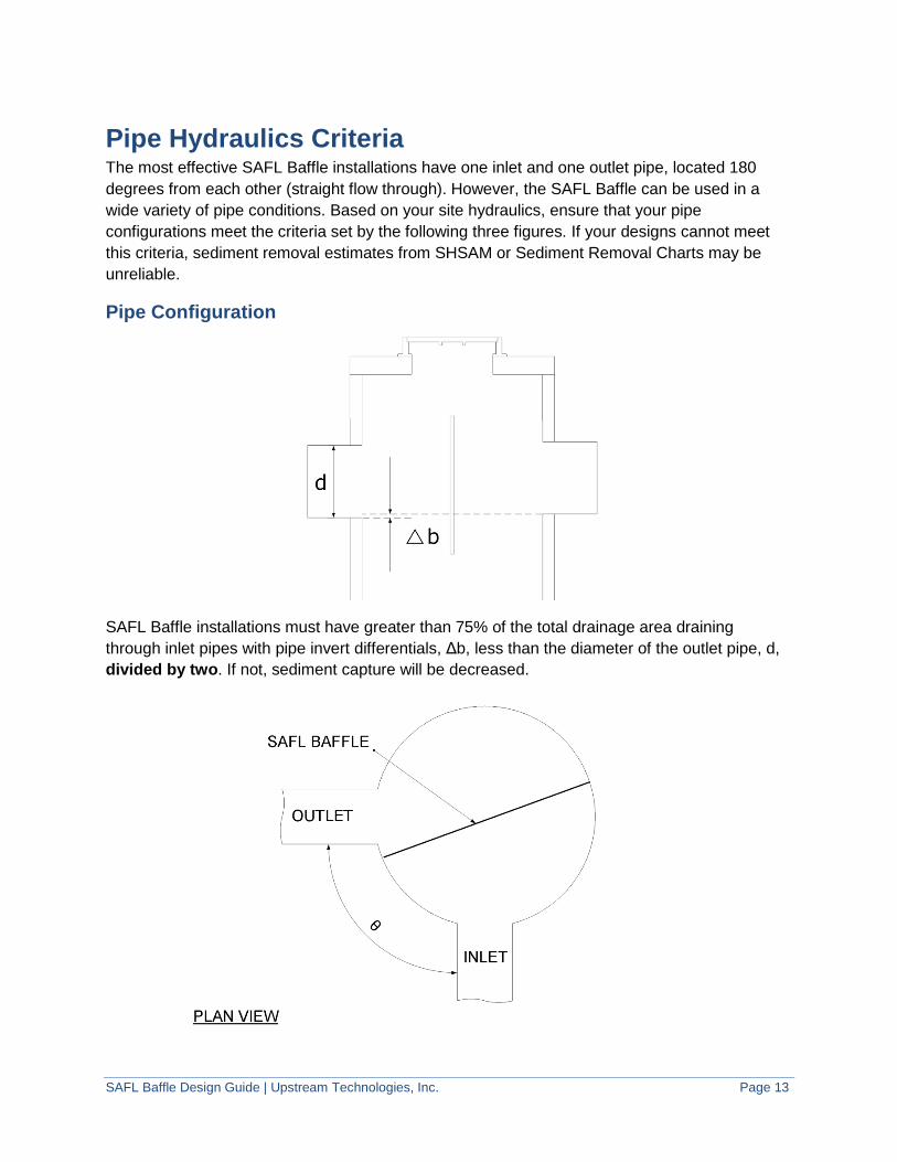
Pipe Hydraulics Criteria The most effective SAFL Baffle installations have one inlet and one outlet pipe, located 180
degrees from each other (straight flow through). However, the SAFL Baffle can be used in a
wide variety of pipe conditions. Based on your site hydraulics, ensure that your pipe
configurations meet the criteria set by the following three figures. If your designs cannot meet
this criteria, sediment removal estimates from SHSAM or Sediment Removal Charts may be
unreliable.
Pipe Configuration
SAFL Baffle installations must have greater than 75% of the total drainage area draining
through inlet pipes with pipe invert differentials, Δb, less than the diameter of the outlet pipe, d,
divided by two. If not, sediment capture will be decreased.

SAFL Baffle Design Guide | Upstream Technologies, Inc. Page 14
Sump structures with inlet pipes located at angles other than 180 degrees from the outlet pipe
are OK. However, an inlet pipe cannot be located less than 90 degrees from the outlet pipe.
SAFL Baffle installations with multiple inlet pipes work well. However, the angle between the two
inlet pipes, θ1, cannot be greater than 110 degrees. Additionally, the angle from the outlet pipe
to any inlet pipe, θ2, must be greater than or equal to 90 degrees.
Here is another example of multiple inlet pipes. The angle between the two inlet pipes, θ1,
cannot be greater than 110 degrees. Additionally, the angle from the outlet pipe to any inlet
pipe, θ2, must be greater than or equal to 90 degrees.

SAFL Baffle Design Guide | Upstream Technologies, Inc. Page 15
Flow from Above
The SAFL Baffle needs horizontal flow through the structure in order to function as intended.
However, it can accommodate flow from above, provided that there is also horizontal flow that is
at least 3 times the flow from above. The SAFL Baffle will not work in a catch basin that only
has flow from above (from a surface grate or curb inlet).
Headloss
The SAFL Baffle causes headloss within sump structures, but is generally small enough that it
does not prohibitively affect hydraulic grade lines for storm sewer designs. The chart below
shows laboratory testing of a 6-ft diameter, 3-ft deep, circular sump manhole structure with and
without a SAFL Baffle. Likely, your structure has different dimensions than the tested structure,
so a conservative estimate will have to be made to determine how headloss from a SAFL Baffle
will affect your design.

SAFL Baffle Design Guide | Upstream Technologies, Inc. Page 16
SAFL Baffle Size Chart Use the chart below to determine the SAFL Baffle size you need. If you used SHSAM to
determine your sump structure size, use those sump structure dimensions within this form. If
you simply want to improve sediment capture and are not looking to meet a specific goal, use
this form without a SHSAM calculation. If you want to use a structure with a larger diameter or
pipe sizes, give us a call at 651.237.5123 for options. Pricing information can be found at
(http://upstreamtechnologies.us/price.shtml)
Manhole Diameter or Width (Inches)
Diameter of Largest Inlet Pipe (Inches)
SAFL Baffle Width x Heights (Inches)
48 15 48 x 36
48 24 48 x 46
60 15 60 x 36
60 24 60 x 46
60 36 60 x 57
72 15 72 x 36
72 24 72 x 46
72 36 72 x 57
84 15 84 x 36
84 24 84 x 46
84 36 84 x 57
84 54 2 - 84 x 36 STACKED
96 24 96 x 46
96 36 96 x 57
96 54 2 - 96 x 36 STACKED

MANHOLE/CATBASIN COVER AND FRAME - 27" MIN . CLEAR OPENING SMALLER OPENING MAY REQUIRE BAFFLE INSTALLATION PRIOR TO PLACING CASTING STRUCTURES GREATER THAN 60" DIA. MAY REQUIRE SECOND CASTING FOR CLEANING SUMP
18' or 24'
HxW SAFL BAFFLE (AVAILABLE FROM UPSTREAM TECHNOLOGIES 651-237-5123)
000
,·'
::: .
...: i...
M
SAFL BAFFLE INSTALLATION
Detail
000 --- FL □ 'w
000
000
000
000
FRONT SIDE
WIDTH ADJUSTMENT FOR PANEL SIZES
2- 18" PANELS
2- 24" PANELS
3- 18" PANELS
3- 24" PANELS
32"MIN
44"MIN
46"MIN
64"MIN
36"MAX
48"MAX
54"MAX
72"MAX
4"TOTAL
4"TOTAL
8"TOTAL
8"TOTAL
SAFL BAFFLE PANEL
Detail
• DIA. ANCHOR B□L T 2' EMBEDMENT
Hx'w' SAFL BAFFLE I' x I' STEEL TUBE FRAME
SAFL BAFFLE INSTALLATION
Plan
N OTES:
UT I,/ /LOCK \,/ASHER
SAFL BAFFLE ATTACHMENT BOLT
Detail
1) UPSTREAM TECHNOLOGIES INC. IS THE EXCLUSIVE LICENSEE OF THE SAFL BAFFLE.
2) CONTRACTOR MUST VERIFY LOCATION OF CASTING AND STEPS PRIOR TO INSTALLATION OF STRUCTURE.
3) CONTRACTOR STRUCTURES GREATER TH AN 72" REQUIRE SECOND CASTING FOR MAINTENANCE
4) THIS GENERIC DETAIL DOES NOT ENCOMPASS THE SIZING, FIT, ANDAPPLICABILITY OF THE SAFL BAFFLE FOR THIS SPECIFIC PROJECT. IT IS THE ULTIMATE RESPONSIBILITY OF THE DESIGN ENGINEER TO ASSURE THAT THE DESIGN IS IN COMPLIANCE WITH ALL APPLICABLE LAWS AND REGULATIONS. THE SAFL BAFFLE IS A PATENTED TECHNOLOGY OF UPSTREAM TECHNOLOGIES, INC. AND THE UNIVERSITY OF MINNESOTA, NEITHER UPSTREAM TECHNOLOGIES NOR THE UNIVERSITY OF MINNESOT A APPROVES PLANS, SIZING, OR SYSTEM DESIGNS.
THROUGH PIPE CONFIGURATION
SAFL BAFFLE STANDARD DETAIL UPSTREAM TECHNOLOGIES600 County Road D West, Suite 14 NEW BRIGHTON, MN 651-237-5123
Technologies

MANHOLE/CATBASIN COVER AND FRAME - 27" MIN. CLEAR OPENING SMALLER OPENING MAY REQUIRE BAFFLE INSTALLATION PRIOR TO PLACING CASTING STRUCTURES GREATER THAN 60" DIA. MAY REQUIRE SECOND CASTING FOR CLEANING SUMP
18' or 24'
000
000 --- FL □ w'
H xW SAFL BAFFLE (AVAILABLE FROM UPSTREAM TECHNOLOGIES 651-237-5123) 000
SAFL BAFFLE INSTALLATION
Detail
000
000
000
FRONT SIDE
SAFL BAFFLE PANEL
Detail
WIDTH ADJUSTMENT FOR PANEL SIZES
2- 18" PANELS 2- 24" PANELS 3- 18" PANELS 3- 24" PANELS
32"MIN 44"MIN 46"MIN 64"MIN
36"MAX 48"MAX 54"MAX 72"MAX
4"TOTAL 4"TOTAL 8"TOTAL 8"TOTAL
MOUNT BAFFLE AS CLOSE TO OUTLET PIPE AS ALLOWABLE, AND ROTATE THE BAFFLE AS NEAR TO PERPENDICULAR TO INLET PIPE AS POSSILBLE
' DIA. ANCHOR B□L T 2' EMBEDMENT
1' x l' STEEL TUBE FRAME
UT V/LDCK VASHER
H x V SAFL BAFFLE
SAFL BAFFLE INSTALLATION
Plan
NOTES:
SAFL BAFFLE ATTACHMENT BOLT
Detail
NINETY DEGREE PIPE CONFIGURATION
1) UPSTREAM TECHNOLOGIES INC. IS THE EXCLUSIVE LICENSEE OF THE SAFL BAFFLE.
2) CONTRACTOR MUST VERIFY LOCATION OF CASTING AND STEPS PRIOR TO INSTALLATION OF STRUCTURE.
3) CONTRACTOR STRUCTURES GREATER TH AN 72" REQUIRE SECOND CASTING FOR MAINTENANCE
4) THIS GENERIC DETAIL DOES NOT ENCOMPASS THE SIZING, FIT, ANDAPPLICABILITY OF THE SAFL BAFFLE FOR THIS SPECIFIC PROJECT. IT IS THE ULTIMATE RESPONSIBILITY OF THE DESIGN ENGINEER TO ASSURE THAT THE DESIGN IS IN COMPLIANCE WITH ALL APPLICABLE LAWS AND REGULATIONS. THE SAFL BAFFLE IS A PATENTED TECHNOLOGY OF UPSTREAM TECHNOLOGIES, INC. AND THE UNIVERSITY OF MINNESOTA, NEITHER UPSTREAM TECHNOLOGIES NOR THE UNIVERSITY OF MINNESOT A APPROVES PLANS, SIZING, OR SYSTEM DESIGNS.
SAFL BAFFLE STANDARD DETAIL UPSTREAM TECHNOLOGIES600 County Road D West, Suite 14 NEW BRIGHTON, MN 651-237-5123
Technologies

MANHOLE/CATBASIN COVER AND FRAME - 27" MIN. CLEAR OPEN ING SMALLER OPEN ING MAY REQUIRE BAFFLE INSTALLATION PRIOR TO PLACING CASTING STRUCTURES GREATER THAN 60" D IA. MAY REQUIRE SECOND CASTING FOR CLEANING SUMP
18' or 24'
H xW SAFL BAFFLE (AVAILABLE FROM UPSTREAM TECHNOLOGIES 651-237-5123)
000
000
000
--- FLO\./
SAFL BAFFLE INSTALLATION
Detail
Hx\./ SAFL BAFFLE
SAFL BAFFLE INSTALLATION
Plan
NOTES:
000
000
000
FRONT SIDE
WIDTH ADJUSTMENT FOR PANEL S IZES
2- 18" PANELS 2- 24" PANELS 3- 18" PANELS 3- 24" PANELS
32"MIN 44"MIN 46"MIN 64"MIN
36"MAX 48"MAX 54"MAX 72"MAX
4"TOTAL 4"TOTAL 8"TOTAL 8"TOTAL
SAFL BAFFLE PANEL
Detail
' DIA. ANCHOR B□L T 2' EMBEDMENT
1' x 1' STEEL TUBE FRAME
UT \.//LOCK \./ASHER
SAFL BAFFLE ATTACHMENT BOLT
Detail
MULTIPLE INLET PIPE CONFIGURATION
1) UPSTREAM TECHNOLOGIES INC. IS THE EXCLUSIVE LICENSEE OF THE SAFL BAFFLE.
2) CONTRACTOR MUST VERIFY LOCATION OF CASTING AND STEPS PRIOR TO INSTALLATION OF STRUCTURE.
3) CONTRACTOR STRUCTURES GREATER TH AN 72" REQUIRE SECOND CASTING FOR MAINTENANCE
4) THIS GENERIC DETAIL DOES NOT ENCOMPASS THE SIZING, FIT, ANDAPPLICABILITY OF THE SAFL BAFFLE FOR THIS SPECIFIC PROJECT. IT IS THE ULTIMATE RESPONSIBILITY OF THE DESIGN ENGINEER TO ASSURE THAT THE DESIGN IS IN COMPLIANCE WITH ALL APPLICABLE LAWS AND REGULATIONS. THE SAFL BAFFLE IS A PATENTED TECHNOLOGY OF UPSTREAM TECHNOLOGIES, INC. AND THE UNIVERSITY OF MINNESOTA, NEITHER UPSTREAM TECHNOLOGIES NOR THE UNIVERSITY OF MINNESOT A APPROVES PLANS, SIZING, OR SYSTEM DESIGNS.
SAFL BAFFLE STANDARD DETAIL UPSTREAM TECHNOLOGIES600 County Road D West, Suite 14 NEW BRIGHTON, MN 651-237-5123

MANHOLE/CATBASIN COVER AND FRAME - 27" MIN. CLEAR OPENING SMALLER OPENING MAY REQUIRE BAFFLE INSTALLATION PRIOR TO PLACING CASTING STRUCTURES GREATER THAN 60" D IA. MAY REQUIRE SECOND CASTING FOR CLEAN ING SUMP
18' or 24'
HxW SAFL BAFFLE (AVA ILABLE FROM UPSTREAM TECHNOLOGIES 651-237-5123)
000
-==2=:;::::::: T.:r·
SAFL BAFFLE INSTALLATION
Detail
Hx \,/ SAFL BAFFLE
SAFL BAFFLE INSTALLATION
Plan
NOTES:
000 --- FLD\J
000
000
000
000
FRONT SIDE
WIDTH ADJUSTMENT FOR PANEL S IZES
2-2-3-3-
18" PANELS 32"MIN 36"MAX 4"TOTAL 24" PANELS 44"MIN 48"MAX 4"TOTAL 18" PANELS 46"MIN 54"MAX 8"TOTAL 24" PANELS 64"MIN 72"MAX 8"TOTAL
SAFL BAFFLE PANEL
Detail
' DIA. ANCHOR B□L T 2' EMBEDMENT
I' x 1' STEEL TUBE FRAME
UT vi /LOCK VASHER
SAFL BAFFLE ATTACHMENT BOLT
Detail
SIDE INLET PIPE CONFIGURATION
1) UPSTREAM TECHNOLOGIES INC. IS THE EXCLUSIVE LICENSEE OF THE SAFL BAFFLE.
2) CONTRACTOR MUST VERIFY LOCATION OF CASTING AND STEPS PRIOR TO INSTALLATION OF STRUCTURE.
3) CONTRACTOR STRUCTURES GREATER TH AN 72" REQUIRE SECOND CASTING FOR MAINTENANCE
4) THIS GENERIC DETAIL DOES NOT ENCOMPASS THE SIZING, FIT, ANDAPPLICABILITY OF THE SAFL BAFFLE FOR THIS SPECIFIC PROJECT. IT IS THE ULTIMATE RESPONSIBILITY OF THE DESIGN ENGINEER TO ASSURE THAT THE DESIGN IS IN COMPLIANCE WITH ALL APPLICABLE LAWS AND REGULATIONS. THE SAFL BAFFLE IS A PATENTED TECHNOLOGY OF UPSTREAM TECHNOLOGIES, INC. AND THE UNIVERSITY OF MINNESOTA, NEITHER UPSTREAM TECHNOLOGIES NOR THE UNIVERSITY OF MINNESOT A APPROVES PLANS, SIZING, OR SYSTEM DESIGNS.
SAFL BAFFLE STANDARD DETAIL UPSTREAM TECHNOLOGIES600 County Road D West, Suite 14 NEW BRIGHTON, MN 651-237-5123

SAFL Baffle Design Guide | Upstream Technologies, Inc. Page 21
Specification SECTION XX XX XX
SAFL BAFFLE
(Items highlighted in yellow must be modified to fit the specific project)
PART 1 GENERAL
1.01 SUMMARY
A. Section Includes:
1. Materials
2. Site Preparation
3. Foundation Placement
4. Modular Block Unit Placement
5. Backfill Placement
6. Compaction
B. Related Sections:
1. Section XX XX XX – Sump Manhole
2. Section XX XX XX – Castings (Be sure
to specify 27-inch inside diameter
castings on manholes with SAFL Baffle)
C. Method of Measurement:
1. Measure per complete baffle assembly
installed.
D. Basis of Payment:
1. Payment shall cover supply and
installation of the SAFL Baffle and other
appurtenant materials required for
installation as shown on the construction
drawings. It shall include all
compensation for labor, materials,
supplies, and equipment associated with
installation of the SAFL Baffle in a sump
manhole.
2. Payment for the SAFL Baffle will be
based on the Contract Unit Price listed on
the Bid Form.
1.02 REFERENCES
A. All stainless steel shall be Type 304.
B. ASTM
1. A380 – Standard Practice for Cleaning,
Descaling, and Passivation of of Stainless
Steel Parts, Equipment, and Systems
C. ANSI:
1. B 18.2 – Standard Dimensions for Bolts
D. SHSAM software by Barr Engineering,
available for download at:
https://www.barr.com/WhatsNew/SHSAM/
SHSAMapp.asp
1.03 DESCRIPTION
A. Furnish and install SAFL Baffles as
manufactured by Upstream Technologies
Inc or approved equal, to the dimensions and
elevations shown on the shop drawings.
B. Furnish and install appurtenant materials
required for installation of the SAFL Baffles
or approved equal as shown on the shop
drawings.
C. The average sediment removal efficiency of
the sump manhole with the SAFL Baffle or
approved equal must be ___% or higher,
according to the SHSAM software output,
using the following inputs:
1. 15-minute Rainfall data from the NOAA
weather station at______, from years
______ through _______
2. Janna-Omid Particle Size Distribution
3. Watershed size of ____ acres
4. Hydraulic length of ______ feet
5. ____% impervious area
SAFL Baffle Design Guide | Upstream Technologies, Inc. Page 22
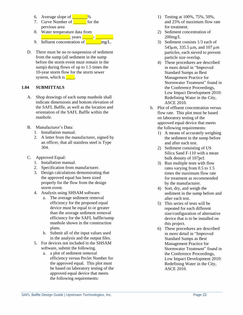
6. Average slope of _______%
7. Curve Number of ______ for the
pervious area
8. Water temperature data from
_____________, years _____- ________
9. Influent concentration of _______mg/L.
D. There must be no re-suspension of sediment
from the sump (all sediment in the sump
before the storm event must remain in the
sump) during flows of up to 1.5 times the
10-year storm flow for the storm sewer
system, which is ____.
1.04 SUBMITTALS
A. Shop drawings of each sump manhole shall
indicate dimensions and bottom elevation of
the SAFL Baffle, as well as the location and
orientation of the SAFL Baffle within the
manhole.
B. Manufacturer’s Data:
1. Installation manual.
2. A letter from the manufacturer, signed by
an officer, that all stainless steel is Type
304.
C. Approved Equal:
1. Installation manual.
2. Specification from manufacturer.
3. Design calculations demonstrating that
the approved equal has been sized
properly for the flow from the design
storm event.
4. Analysis using SHSAM software.
a. The average sediment removal
efficiency for the proposed equal
device must be equal to or greater
than the average sediment removal
efficiency for the SAFL baffle/sump
manhole shown in the construction
plans.
b. Submit all of the input values used
in the analysis and the output files.
5. For devices not included in the SHSAM
software, submit the following.
a. a plot of sediment removal
efficiency versus Peclet Number for
the approved equal. This plot must
be based on laboratory testing of the
approved equal device that meets
the following requirements:
1) Testing at 100%, 75%, 50%,
and 25% of maximum flow rate
for treatment.
2) Sediment concentration of
200mg/L
3) Sediment consists 1/3 each of
545m, 335.5m, and 107m
particles, each sieved to prevent
particle size overlap.
4) These procedures are described
in more detail in “Improved
Standard Sumps as Best
Management Practice for
Stormwater Treatment” found in
the Conference Proceedings,
Low Impact Development 2010:
Redefining Water in the City,
ASCE 2010.
b. Plot of effluent concentration versus
flow rate. This plot must be based
on laboratory testing of the
approved equal device that meets
the following requirements:
1) A means of accurately weighing
the sediment in the sump before
and after each test.
2) Sediment consisting of US
Silica Sand F-110 with a mean
bulk density of 107pcf.
3) Run multiple tests with flow
rates varying from 0.5 to 1.5
times the maximum flow rate
for treatment as recommended
by the manufacturer.
4) Sort, dry, and weigh the
sediment in the sump before and
after each test.
5) This series of tests will be
repeated for each different
size/configuration of alternative
device that is to be installed on
this project.
6) These procedures are described
in more detail in “Improved
Standard Sumps as Best
Management Practice for
Stormwater Treatment” found in
the Conference Proceedings,
Low Impact Development 2010:
Redefining Water in the City,
ASCE 2010.

SAFL Baffle Design Guide | Upstream Technologies, Inc. Page 23
1.05 SAMPLING AND TESTING
A. The Owner or authorized representative
shall be accorded proper facilities to inspect
and sample baffle panels/frames from lots
ready for delivery. The Contractor shall
notify the authorized representative in
writing a minimum of 5 calendar days prior
to shipment of materials.
B. The Contractor shall establish and maintain
quality control for the work under this
section to assure compliance with contract
requirements and maintain records of its
quality control for all construction
operations including but not limited to the
following:
1. Alignment Tolerances:
a. Horizontal
b. Vertical
c. Plumbness
d. Gaps between baffle units or
between baffle units and wall of
sump.
2. Torque applied to concrete anchor bolts
at the frame side rails and torque applied
to eye-bolts and set screws during
assembly of the SAFL baffle shall be to
manufacturer’s specifications.
1.06 QUALITY ASSURANCE
A. Preinstallation Meetings: Conduct
conference at Site to comply with the
requirements of Section XX XX XX.
1.07 DELIVERY, STORAGE, AND
HANDLING
A. Check the materials upon delivery to assure
that proper material has been received.
B. Store the SAFL Baffles in an area where
they will be protected from construction
traffic and caustic/corrosive chemicals.
C. Prevent excessive mud, wet cement, grout,
epoxy and like materials from affixing
themselves to the materials until each SAFL
Baffle is installed and accepted. Damaged
material shall not be installed in any
manhole and shall be replaced at no
additional cost to Owner.
PART 2 PRODUCTS
2.01 MATERIALS
A. Baffle Panels
1. Physical Properties:
a. Stainless Steel:
1) Shall be Type 304
2) Minimum yield strength shall be
31,000 psi.
b. Minimum dimensions as follows:
1) Unit width: 18 or 24 inches
2) Unit Height: 34, 44, or 54
inches
3) Thickness: 1/8 inch
B. Frame
1. Shall consist of 1” x 1” square stainless
steel tube with 1/8” thick walls
2. Connector on top and bottom frame rails
shall consist of a solid square stainless
steel bar measuring 7/8” x 7/8” in cross
section.
C. Anchor Bolts
1. Must be 3/8” diameter
2. Must have a mechanism that expands
against the sides of a hole drilled in the
concrete sump wall, to secure the bolt.
3. Minimum pullout strength of each
anchor shall be 2200 pounds and
minimum shear strength shall be 2500
pounds.
D. Screws and Bolts:
1. Mn/DOT 3319.2E

SAFL Baffle Design Guide | Upstream Technologies, Inc. Page 24
PART 3 EXECUTION
3.01 INSTALLATION PRIOR TO
DELIVERY
A. The SAFL Baffle may be installed in a new
manhole at the precast concrete plant, prior
to delivery to the project site.
B. The SAFL Baffle must be installed
perpendicular to the inlet pipe, at the
horizontal midpoint of the sump.
C. Use 3/8” dimeter bolts, cast into the concrete
manhole wall, or use 3/8” diameter anchor
bolts installed in a hole drilled in the
concrete wall. Anchor bolts must be
embedded 2 inches into the concrete sump
wall and have a mechanism that expands
against the sides of the drilled hole.
D. The bottom of the SAFL Baffle shall be
established at the elevation shown on the
plans, with a tolerance of +/- 0.5 inch.
E. The top and bottom rails of the baffle must
be level, with no tolerance on levelness.
F. Follow the manufacturer’s installation
instructions.
G. The baffle panels must be vertical (plumb)
when the installation is complete.
H. Upon completion of installation, baffle
panels may overlap as much as 2 inches, or
the edges of adjacent panels may touch one
another without overlapping. However, no
gap is allowed between baffle panels.
3.02 INSTALLATION ON-SITE
A. The SAFL Baffles may be installed on-site,
after the manholes have been constructed.
B. It is the contractor’s responsibility to have
all OSHA required safety equipment for
confined space entry. It is also the
contractor’s responsibility to comply with
all OSHA rules and procedures for confined
space entry, and any other OSHA rules
which are applicable for this work.
C. Follow manufacturer’s instructions for
installation.
D. The SAFL Baffle must be installed
perpendicular to the inlet pipe, at the
horizontal midpoint of the sump.
E. The bottom of the SAFL Baffle shall be
established at the elevation shown on the
plans, with a tolerance of +/- 0.5 inch.
F. Use 3/8” dimeter bolts, cast into the concrete
manhole wall, or use 3/8” diameter anchor
bolts installed in a hole drilled in the
concrete wall. Anchor bolts must be
embedded 2 inches into the concrete sump
wall and have a mechanism that expands
against the sides of the drilled hole.
G. The top and bottom rails of the baffle must
be level, with no tolerance on levelness.
H. The baffle panels must be vertical (plumb)
when the installation is complete.
I. Upon completion of installation, baffle
panels may overlap as much as 2 inches, or
the edges of adjacent panels may touch one
another without overlapping. However, no
gap is allowed between baffle panels.
3.03 APPROVED EQUAL
A. Basis for approval – devices in the SHSAM
software.
1. Sediment removal efficiency from
SHSAM software output that meets or
exceeds the average sediment removal
efficiency given in section 1.03(C).
2. Meets or exceeds the re-suspension
requirements in section 1.03(D).
3. Device must be able to be cleaned
out/emptied from above using a vactor
truck, without dismantling the device or a
worker entering the device.
4. Acceptance is subject to the review of
both the engineer and the Owner.
B. Basis for approval – devices not in SHSAM
software.
1. The plot of the efficiency versus Peclet
number for the approved equal must plot
on or above the plot for the SAFL Baffle,

SAFL Baffle Design Guide | Upstream Technologies, Inc. Page 25
which is plotted on a semi-logarithmic
scale and defined as follows:
Peclet Number
(Pe)
x-axis
Removal Efficiency
(y-axis
0.01 0%
0.1 5%
0.3 12%
0.5 22%
1.0 40%
2.0 75%
3.0 100%
10.0 100%
20.0 100%
2. The plot of effluent concentration versus
flow rate for the approved equal must be
at or below the plot for the SAFL Baffle.
3. Device must be able to be cleaned
out/emptied from above using a vactor
truck, without dismantling the device or a
worker entering the device.
4. Acceptance is subject to review of both
the engineer and the Owner.
C. If an equivalent device is approved, the
contractor will need to supply a specification
from the device manufacturer that describes
the material and installation requirements of
that device. This specification will govern
the installation of the approved equal.
3.04 QUALITY CONTROL
A. Establish and maintain quality control for
the work under this section to assure
compliance with contract requirements and
maintain records of its quality control for all
construction operations including but not
limited to the following:
1. Alignment Tolerances:
a. Horizontal
b. Vertical
c. Plumbness
d. Gaps between wall units
2. Furnish a copy of the records of
inspection, as well as the records of
corrective action taken to Engineer.
END OF SECTION
SAFL Baffle Design Guide | Upstream Technologies, Inc. Page 26
Maintenance & Monitoring The following maintenance and monitoring recommendations come from the research report
titled Assessment and Recommendations for the Operation of Standard Sumps as Best
Practices for Stormwater Treatment (Volume 2) by Kurtis McIntire, Adam Howard, Omid
Mohseni and John Gulliver, published May 2012, available at:
(www.cts.umn.edu/Publications/.../pdfdownload.pl?id=1722)
Excerpt begins:
As with any stormwater treatment device, the SAFL Baffle must be maintained.
Visual Inspection
After installing the SAFL Baffle into a sump manhole, the system should be visually inspected
three times per year for the first two years. During this inspection, it is important to determine
whether or not the SAFL Baffle is physically compromised, the sediment depth in the sump, and
remove any debris from the sump.
Additionally, the sediment captured at the bottom of the sump should be measured. This can be
done by using a stick ruler with a point that can penetrate the sediment and reach the concrete
bottom of the sump, and a stick ruler with a flat disk that will stop when reaching the sediment.
The difference in distance measurements between these rulers is the depth of sediment in the
sump. Several measurements should be taken to determine an average sediment depth in the
sump, because the sediment bed will not be perfectly flat.
When visually inspecting the SAFL Baffle, it is important to check for clogging due to debris like
trash and vegetation. Debris clogging the SAFL Baffle can cause washout in shallow sumps,
Any debris stuck in the sump upstream of the SAFL Baffle should be removed. Afterwards,
debris stuck on the SAFL Baffle should be removed.
Visual Inspection Checklist:
1. Previous Inspection - Has this SAFL Baffle been inspected before? If so, when?2. Rainfall - Has it rained recently? If so, when? How many inches?3. Access - Is the sump manhole accessible? If not, why?4. Pipes - How many pipes connect to the sump?5. Flow - How does water flow through the sump?6. Debris - Is trash or vegetation in the sump? If so, what types of trash or vegetation are
present?7. Structural Integrity - Is the SAFL Baffle broken? Is it rusting? Are there pieces of the
baffle that have become dislodged? Do any parts of the SAFL appear weak ordamaged?
8. Clogging - Is anything clogging the baffle? If so, what is causing the clogging?
Sump Cleaning
Sump cleaning needs to take place to ensure maximum capture of sediment from stormwater. If
sediment in the sump is not removed, sediment will accumulate at the bottom of the sump,

SAFL Baffle Design Guide | Upstream Technologies, Inc. Page 27
causing the sediment bed to rise towards the bottom of the SAFL Baffle. In turn, washout can
occur during storm events.
Cleaning should be done with a truck mounted vacuum. If the manhole's casting and SAFL
Baffle is designed properly, the SAFL Baffle should not get in the way of the truck's vacuum.
Once the sediment and debris is removed from the sump, it can be disposed.
Excerpt ends

SAFL Baffle Design Guide | Upstream Technologies, Inc. Page 28
Nonstandard Designs The SAFL Baffle can be used in a wide variety of situations, but was laboratory tested in a
limited number of configurations. Sediment capture of sump structures with SAFL Baffle designs
that deviate from the recommendations of this document cannot be accurately determined.
If unsure of your design, an engineer at Upstream Technologies will be glad to help. Please
give us a call at 651.237.5123.
Sump Structures with less than 3-ft of depth
You can install a SAFL Baffle, but it will not capture as much sediment as deeper sump
manholes and it will need to be cleaned more frequently
Curb to sump structure
The goal here is to get water traveling into the sump at a roughly horizontal direction. This
can be done by altering local drainage (see image below) or by installing a curb inlet grate
that routes water to a horizontal vector.
Place the manhole behind the curb instead of below it, and extend a pipe from the curb inlet
to the manhole. Use a curb inlet casting such as R-3262 or R-3268 from Neenah Foundry
that directs water into a pipe behind the curb. These castings can be found here:
http://www.nfco.com/municipal/products/curb-opening/