sae mini baja 2014-2015 - welcome - college of … mini baja 2014-2015 by ahmed alnattar, neil gehr,...
TRANSCRIPT
SAE Mini Baja 2014-2015 By
Ahmed Alnattar, Neil Gehr, and Matthew Legg
Team 11
Project Proposal Document
December 5, 2014
Submitted towards partial fulfillment of the requirements for
Mechanical Engineering Design I – Fall 2014
Department of Mechanical Engineering
Northern Arizona University Flagstaff, AZ 86001

2
Table of Contents
Introduction…………………………………………………………………………... 3
Problem Statement…………………………………………………………………… 3
Customer Needs………………………………………………………………………. 4
Goal……………………………………………………………………………………. 4
Constraints……………………………………………………………………………. 5
Objectives / QFD……………………………………………………………………… 5
Project Planning………………………………………………………………………. 6
Concept Generation…………………………………………………………………... 7
Truck Frame Design………………………………………………………….. 7
Old Volkswagen Buggy……………………………………………………….. 8
Front Bracing Design…………………………………………………………. 9
Rear Bracing Design……………………………………………………… ….. 10
Front Supported Design………………………………………………………. 11
Compact Concept Design……………………………………………………... 11
Decision Matrix and Criteria…………………………………………………………. 12
Frame Designs…….…………………………………………………………………… 13
Front Supported Design…………………………………………………….… 13
Front Bracing Design…………………………………………………………. 14
Testing and Calculations……………………………………………………………… 15
Simulation Results…………………………………………………………………….. 19
Final Frame Design……………………………………………………………………. 21
Bill of Materials………………………………………………………………………... 23
Conclusion…………………………………………………………………………...…. 25
References………………………………………………………………………………. 26
Appendix…………………………………………………………………………...…… 27

3
Introduction
Society of Automotive Engineers (SAE) is a world known association for setting
standards in the automotive industry around the world. SAE is also interested in collegiate
opportunities and participation to help educate and stimulate future engineers. For many years
SAE has helped students of all ages to develop their skills and knowledge of mechanical
operations and properties. For NAU, the senior capstone mechanical engineering students are
participating in competitions held by SAE in the fields of the regular class aero, the micro aero,
the moon buggy and the mini Baja.
The mini Baja project is a compilation of design, from the ground up, of suspension,
steering, drivetrain, frame, wheels, and overall presentation with respect to cost. The vehicle
needs to be built to handle off road conditions and be competitive in different dynamic events
against other schools teams. The events at the competition that the Baja vehicle will have to go
through are acceleration, hill climb/traction event, maneuverability, endurance, and the sales
presentation event. Each event is worth a certain amount of points, adding up to a total of 750
allowable points. Based on how the vehicle does in each event, the team will be ranked
accordingly out of 100 positions. The closer you are to being rank 1, the better your vehicle
overall is. This 2014-2015 competitions rules and locations have been released by SAE, as every
year there are changes made to requirements and locations.
This report provides a complete discussion about the team’s client, goals, constraints, and
objectives. It will provide a QFD along with a projected timeline for the coming semester of this
project. It will show six basic frame designs and decision matrix that the team used to choose
which two designs that would be built and tested in SolidWorks. Following will discuss the
scenarios and calculations used for the two frames along with the analysis of the two designs. I
final analysis will be presented along with a bill of materials and proposal.
Problem Statement
Here at Northern Arizona University (NAU), Dr. John Tester has assigned the senior
design project of the SAE Mini Baja to a set of senior mechanical engineering students. The task
is to design and build the SAE mini Baja for the 2015 SAE competitions that will outperform Dr.
John Tester’s SAE mini Baja of 2014.

4
For the capstone project of the mini Baja, the frame team is focusing on the design and
building of a single seat mini Baja frame that a fictitious firm would want to manufacture. The
frame will be put through a series of dynamic events that will test the structural integrity.
Customer Needs
Dr. Tester’s highest concern with the previous Baja vehicle was the weight. Last year’s
mini Baja vehicle weighed about 650 lbs. in total [1]. This caused them to have an acceleration
struggle while competing with the other mini Baja vehicles that had better power to weight
ratios. Dr. Tester also needs the front of the frame to have a better angle for clearing obstacles
and climbing hills [2].
Goals
As being the frame team of the mini Baja vehicle, our goals are many. One is to design
and build a light weight frame that will meet strength, safety, and dimension requirements for
SAE Baja competition(s) and our customer needs. Another goal is to integrate all additional
equipment into the frame with mounting tab. Last year’s mini Baja team did not design the frame
with the thought or consideration of how the suspension and other components of the vehicle
were going to be installed, and thus had to increase the number of structural members along with
the weight of the vehicle. This year, the frame team is going to make sure to consider all other
components of the vehicle when designing the frame. A third goal for us is to try and incorporate
packaged extras that the vehicle can have installed while not being used in the competitions such
as a glove box in the front of the vehicle, a speaker system, a winch, and additional body
paneling for cosmetics. These extra will attract a buyer’s eye, while not affecting the ability of
the Baja while it is being used for competitions. The driver ergonomic designs is another goal for
the frame team because comfortability is important, but not too important. The driver should not
get fatigued or cramped while driving the vehicle in competition while being able to drive with
ease. While keeping all of these goals in mind, we realize that the frame needs to be as
inexpensive as possible to manufacture, but good enough to outperform previous NAU Mini
Baja teams in the competitions with our current constraints.

5
Constraints
Most of the constraints that we must adhere to are within the SAE Mini Baja rules which
can be found on their web page. A few extra constraints that we are being given is that the total
width of the vehicle must not be wider than 59 inches and that the total weight must not be
exceed 450 lbs.
Objectives
The objectives for the frame team are to:
Design and build a light weight frame of maximum 150 pounds
Design a frame that can be built within a short amount of time
High enough strength to withstand a roll over and/or a collision
Build the frame with considerations to all other components of the vehicle with respect to
the overall dimensions so that it may be transported to and from competitions with ease
QFD
The following is the QFD with our engineering requirements and customer’s needs along
with the House of Quality that shows the positive or negative correlations. This chart also shows
the NAU’s and ASU’s previous mini Baja strengths in correlation with Dr. Tester’s
requirements.

6
Project Planning
Gantt Project was used to develop a timeline for the next two semesters. Based off the
Gantt chart below, the frame team’s main goal is to have a frame design approved by Dr. Tester
and build a prototype frame as quickly as possible for testing. Once the frame has started to be
built, the team can then focus on other designs and builds for the overall vehicle.
Figure 1 - QFD with HOQ: The above figure shows the relationships between customer requirements and the engineering requirements.

7
Concept Generation
The team came up with six different designs for the overall frame. Below are the
descriptions of each design.
Truck Frame Design
One of the frame design concepts was a truck frame design. The concept behind this
frame design was to build a vehicle as a truck with toe and chamber off road racing suspension.
Since a lot of trucks are built to be driven rough road and under rough conditions, a truck design
can be a durable baja frame. In addition, the SAE mini baja competition is going to take a place
in Portland, Oregon where the competitor mini baja vehicles are going to be tested under rough
road conditions against each other, and in order to last through the SAE competition dynamic
events, our mini baja team needs to build a vehicle that is tough in strength, light enough to
complete the competition successfully. The advantage to using this design is due to its light
weight and unique. In all the previous competitions, there has never been a frame design that had
a bed, which would be appealing to a fictitious buyer. The disadvantage to this design would be
not much room the other components such as the motor. A sketch and an image are included
below, to better represent the idea of the Truck Frame Design (Image 1)
Figure 2 – Gantt chart: The following chart above shows a visual description what the frame team will be working on for the next two months.

8
Image 1: Truck Frame Design [9]
Old Volkswagen Design
The Old Volkswagen Buggy Design is a baja frame that is built like an old Volkswagen
buggy vehicle with toe and chamber off road racing suspension. Since this is a common off road
vehicle that is small, it would be appealing for this competition since the frame for these vehicles
perform well in off road environments. The advantages to this design is the size, which would
decrease weight and cost along with a unique oval design. This design also can be equipped with
a front trunk that is also appealing to a fictitious company. The disadvantage to this design would
be the design would be hard to keep within SAE Baja 2015 Rules. A sketch and an image are
included further, so the idea can be better seen and visualized (Image 2).
Image 2: Old Volkswagen Design [10]

9
Front Bracing Design
Below is Image 3, a right side view of the frame design.
Image 3: Front Bracing Design
The Front bracing concept also incorporates the minimum amount of required members
needed for front bracing due to the SAE Rules for 2015. This design also has a front approach
angle integrated as the Rear Bracing Design. Some advantages of this design are that this design
allows for pure customization of the rear of the vehicle for suspension and drivetrain sub groups
to install their designs with ease. It adds weight to the front of the vehicle which positively
impacts the weight front to rear weight ratio. As an added strength component, the rear roll hoop
has an extra member added. The main disadvantage of this design is that there is an added
member in the front of the vehicle that can lower the vision of the driver.

10
Rear Bracing Design
Below is Image 4, a right side view of the rear bracing design.
Image 4: Rear Bracing Design
The rear bracing concept incorporates the minimum amount of members required by the
rules established by the SAE Rules for 2015. Along with having the minimum amount of
members required, the frame design also has a front that is angled for approaching hills and
rocks. Some advantages to this design: It allows for a simpler firewall design because of the
extra added support members that will be in the rear of the vehicle, behind the driver. The rear
bracing member can be moved depending on the needs of the suspension and drivetrain team as
show below in Image 5 with the blue dotted lines.
Image 5: Rear Supporting Members [11]

11
The main disadvantage to the rear bracing design is that it negatively impacts the weight
ratio of the vehicle with more weight being added to the rear of the vehicle.
Front Supported Design
Front Supported is a front supported frame design
which conforms to the SAE Baja 2015 Rules. The focus of
this design was to decrease the length (Δy) of the frame as
much as possible to keep the weight down. Also to decrease
weight, this concept uses as few as members as possible.
The advantages to using this design is that since there are
few members, it would be simple to build. This would also
decrease the cost of the frame along with the weight. The
disadvantages to this design is that it would not be as strong
as some of the other designs due to fewer number of
members supporting the frame. Also since it is taller, it has
a higher chance to flip due to a higher center of gravity.
Compact Concept Design
Compact Concept Design 2 is a front supported
frame design which conforms to the SAE Baja 2015 Rules.
The focus of this design was to decrease the width (Δx) and
the height (Δz) as much as possible to keep the weight down.
The advantages to using this design is that the weight
distribution of the frame will be towards the front, helping
the overall weight distribution. This frame is also short
which allows for a lower center of gravity. The
disadvantages to this design is that it is more complex to
build, which takes longer to build.
Image 6: Compact Concept Design 1
Image 7: Compact Concept Design 2

12
Matrix and Criteria
To determine which designs would be used, the team made a decision matrix with the
following criteria: Overall Weight, Cost, Strength, Room for Modifications, Simplicity, Ability
to Install Accessories, Driver Accessibility. Each criteria was weighted differently, with Overall
Weight and Cost be highest and Ability to Install Accessories being least in points. Each team
member was then given a decision matrix to fill out on their own for the six designs. Table 1
shows the final decision matrix, which is the average points of all the team member’s decision
matrices.
As shown in the Group Decision Matrix (Table 1) the two top designs were the Rear
Bracing Design and the Compact Design 1. Out of the six designs, Rear Bracing Design and the
Compact Design1 won due to how light weight they are. Dr. John Tester explained that his
greatest need for the new frame is for it to be light in weight, which is why the two designs were
chosen from the decision matrix, along with being inexpensive. Now these two design will now
be used to design a single frame that will be presented to Dr. Tester for approval along with
analysis on the frame. Once the team receives approval from Dr. Tester, based off funding, the
team will then start to build a prototype frame for crush testing and more analysis by December
7th.
Table 1: Final Group Decision Matrix

13
Frame Designs
Below, are the descriptions of the two frames, Front Supported and Front Bracing, in
more depth along with figures for visual representation.
Front Supported Design
The Front Supported frame was designed to be compact and light in weight. It is made
designed with 1’’ diameter 4130 chromoly steel with a wall thickness of 0.12’’ which is the
smallest piping allowed in competition. The 2014 Baja frame has a width of 36 inches and length
of 90 inches, while the Front Supported frame has a width of 44 inches and a length of 76 inches.
Along with smaller dimensions, it’s mass of 158lbs which is 100lbs less than the previous Baja’s
frame. The Front Supported frame can be seen below in Figure 4.
Figure 3: Front Supported Frame Design
14
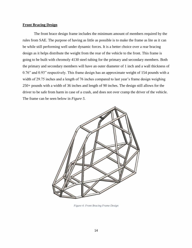
Front Bracing Design
The front brace design frame includes the minimum amount of members required by the
rules from SAE. The purpose of having as little as possible is to make the frame as lite as it can
be while still performing well under dynamic forces. It is a better choice over a rear bracing
design as it helps distribute the weight from the rear of the vehicle to the front. This frame is
going to be built with chromoly 4130 steel tubing for the primary and secondary members. Both
the primary and secondary members will have an outer diameter of 1 inch and a wall thickness of
0.76” and 0.93” respectively. This frame design has an approximate weight of 154 pounds with a
width of 29.75 inches and a length of 76 inches compared to last year’s frame design weighing
250+ pounds with a width of 36 inches and length of 90 inches. The design still allows for the
driver to be safe from harm in case of a crash, and does not over cramp the driver of the vehicle.
The frame can be seen below in Figure 5.
Figure 4: Front Bracing Frame Design

15
Testing and Calculations
For the two final designs of the frame, our frame team used SolidWorks Simulation to
test the stresses, the displacement, and the overall factor of safety for the design upon impact.
The frame team wanted to run a Finite Element Analysis (FEA) to determine the weakest areas
on the frames. This analysis allows us to make any necessary changes before building the actual
frame while ensuring the maximum safety for the driver along with the frame being light in
weight. In order for our frame team to achieve a high quality of frame, the team needs to test the
frame design for multiple scenarios to ensure the safety of the driver. Therefore, the frame
analysis was based on applying four different simulation studies on the two frames, and each
simulation study describes different scenario of collisions. The scenarios tested were drop test,
front impact, rear impact, and side impact. The figure below shows the drop test scenario.
Figure 5: Drop Test Scenario
For the frame drop test (Figure 4), it was assumed that the vehicle rolled over and landed
upside down from a height of 10 feet. In addition, the weight of the baja is 450lbs and the impact
16
time is 0.1 seconds. In order to analyze the frame in a rollover scenario, the following equation
needed to be used to determine the force of impact.
𝐹 = 𝑚 ∙√2𝑔ℎ
𝑡 (1)
𝐹 = 𝑡𝑜𝑡𝑎𝑙 𝑓𝑜𝑟𝑐𝑒 (𝑙𝑏𝑓)
𝑚 = 𝑜𝑏𝑗𝑒𝑐𝑡 𝑚𝑎𝑠𝑠 (𝑙𝑏𝑚)
𝑔 = 𝑎𝑐𝑐𝑒𝑙𝑒𝑟𝑎𝑡𝑖𝑜𝑛 𝑜𝑓 𝑔𝑟𝑎𝑣𝑖𝑡𝑦 (𝑓𝑡
𝑠2⁄ )
ℎ = 𝑑𝑟𝑜𝑝 ℎ𝑒𝑖𝑔ℎ𝑡 (𝑓𝑡)
𝑡 = 𝑖𝑚𝑝𝑢𝑙𝑠𝑒 𝑑𝑟𝑜𝑝 𝑡𝑒𝑠𝑡 𝑡𝑖𝑚𝑒 (𝑠)
In order to run the drop test simulation study and receive better test results, the team had
to define the applied force on the chosen beams. This force is the total force Equation (1) divided
by the total length of members force is applied to. Thus, this force can be illustrated as,
𝐹𝑎 =𝐹
𝑙 (2)
𝐹𝑎 = 𝑎𝑝𝑝𝑙𝑖𝑒𝑑 𝑓𝑜𝑟𝑐𝑒 (𝑙𝑏𝑓
𝑖𝑛)
𝐹 = 𝑡𝑜𝑡𝑎𝑙 𝑓𝑜𝑟𝑐𝑒 (𝑙𝑏𝑓)
𝑙 = 𝑡𝑜𝑡𝑎𝑙 𝑙𝑒𝑛𝑔𝑡ℎ 𝑜𝑓 𝑚𝑒𝑚𝑏𝑒𝑟𝑠 𝑓𝑜𝑟𝑐𝑒 𝑖𝑠 𝑎𝑝𝑝𝑙𝑖𝑒𝑑 𝑡𝑜(𝑖𝑛)
For the remaining impact test scenarios to be conducted on the frame in the SolidWorks
simulation studies, a different method to calculate the total force is needed. The total force used
to analyze the front, rear, and side impact tests is different than what is used in the drop test. This
method was applied to all the remaining three simulation studies. Our front, rear, and side impact
simulation studies were tested based on assuming a vehicle weight of 450lbs, an initial impact
velocity of 25mph, and an impulse impact test time of 0.2 seconds. In order to analyze the frame
experiencing front, rear, and side impacts, a mathematical calculation is needed to calculate the
total force. From the total force the team can then determine the applied force to be used for
testing the various impact scenarios. As a result, the following equation is obtained.
17
𝐹 = 𝑚 ∙𝑉0
𝑡 (3)
𝐹 = 𝑡𝑜𝑡𝑎𝑙 𝑓𝑜𝑟𝑐𝑒 (𝑙𝑏𝑓)
𝑚 = 𝑜𝑏𝑗𝑒𝑐𝑡 𝑚𝑎𝑠𝑠 (𝑙𝑏𝑚)
𝑉0 = 𝑖𝑛𝑖𝑡𝑖𝑎𝑙 𝑖𝑚𝑝𝑎𝑐𝑡 𝑣𝑒𝑙𝑜𝑐𝑖𝑡𝑦 (𝑓𝑡
𝑠⁄ )
𝑡 = 𝑖𝑚𝑝𝑢𝑙𝑠𝑒 𝑖𝑚𝑝𝑎𝑐𝑡 𝑡𝑒𝑠𝑡 𝑡𝑖𝑚𝑒 (𝑠).
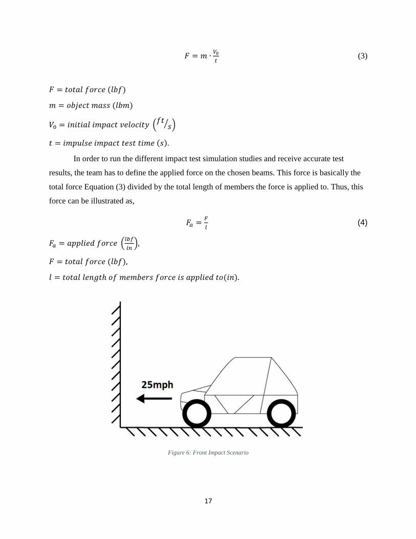
In order to run the different impact test simulation studies and receive accurate test
results, the team has to define the applied force on the chosen beams. This force is basically the
total force Equation (3) divided by the total length of members the force is applied to. Thus, this
force can be illustrated as,
𝐹𝑎 =𝐹
𝑙 (4)
𝐹𝑎 = 𝑎𝑝𝑝𝑙𝑖𝑒𝑑 𝑓𝑜𝑟𝑐𝑒 (𝑙𝑏𝑓
𝑖𝑛),
𝐹 = 𝑡𝑜𝑡𝑎𝑙 𝑓𝑜𝑟𝑐𝑒 (𝑙𝑏𝑓),
𝑙 = 𝑡𝑜𝑡𝑎𝑙 𝑙𝑒𝑛𝑔𝑡ℎ 𝑜𝑓 𝑚𝑒𝑚𝑏𝑒𝑟𝑠 𝑓𝑜𝑟𝑐𝑒 𝑖𝑠 𝑎𝑝𝑝𝑙𝑖𝑒𝑑 𝑡𝑜(𝑖𝑛).
Figure 6: Front Impact Scenario

18
In Figure 6, the front impact scenario is shown as if the 450lb baja vehicle would collide
at an impact velocity of 25mph into a wall. The applied force distribution is applied at the front
members of the vehicle, while the rear-end members of the vehicle are chosen to be fixed.
Figure 7: Rear Impact Scenario
Figure 7 illustrates the impact scenario of the baja vehicle being hit by 450lb baja vehicle
from the rear end. This scenario can be described as if an approaching vehicle collides with the
baja vehicle from the rear at an initial impact velocity of 25mph. The applied force distribution is
applied at the rear end members of the vehicle, while the front of the baja vehicle is chosen to be
fixed.

19
Figure 8: Side Impact Scenario
Figure 8 illustrates the impact scenario of the baja vehicle being hit by 450lb baja vehicle
from the side. This scenario can be described as if a vehicle collides with the baja from the side
at an initial impact velocity of 25mph. The side impact test using SolidWorks is performed by
placing an applied force distribution to the members on one side of the vehicle in a plane, while
the members on the other side of the vehicle are set to be fixed.
Simulation Results
The results generated for the two frames are discussed below, the images generated in
SolidWorks are shown in the Appendix. The factor of safety of the frame has to do with the
material being used and the configuration the members are in when a load is applied. The
material of both is 4130 chromoly steel with a yield strength of 66ksi. The following table shows
the factors of safety for the two frames for each of the tests that were completed.

20
Table 2: Factor of Safeties from the Simulation
As seen from the values obtained for the factors of safety, both vehicles exceed a required
FOS value of two, but the Front Bracing design out performs the Front Supported design.
Deformation of members is also a major concern for the safety of the driver since
crushing the driver is a possibility. In the table below, the maximum deformation for the two
frames can be seen for each of the tests that were completed.
Table 3: Maximum Deformation from the Simulation
As seen from the values obtained for the deformation, both frames have an extremely
small maximum value of deflection proving that both designs are capable of protecting and
insuring the safety of the driver. The front bracing design is shown to deflect less.
The concentration of stresses that the frame members receive are important to know so
that the failure points may be assessed in the most extreme scenarios. In the table below, the
maximum stress for the two frame can be seen for each of the tests that were completed.

21
Table 4: Maximum Stress from the Simulation
As seen from Table 3, the Front Supported frame experiences higher amounts of stress
than the other frame. This would have to due to the frame having less supporting members in
high stress areas. The Front Bracing frame out performs the Front Supported frame.
Based off the results, the team decided that the Front Bracing Frame was the frame that
would be presented to the client and further modified for suspension and drivetrain Teams. This
decision was based on its better performance than the Front Supported Frame.
Final Frame Design
After presenting the Front Bracing Frame to Dr. Tester, suspension, and drivetrain teams,
they were all able to put input into the frame. With their input, the frame was modified for a
finalized frame.
Modifications made to the frame was to have the correct spacing in the front for the
suspension arms. When comparing the Front Supported Frame to the Finalized Frame, the front
becomes more of a box shape and the horizontal members are parallel to each other. This was
need to for the front suspension to work properly. Members have been added near the driver and
in the rear for more stability as requested by Dr. Tester. Lastly, main members will be AISI 4130
steel tubing with a diameter of 1.25 (in) and wall thickness of 0.065 (in), while secondary
members will be 1 (in) diameter and wall thickness of 0.056 (in). The Finalized frame is shown
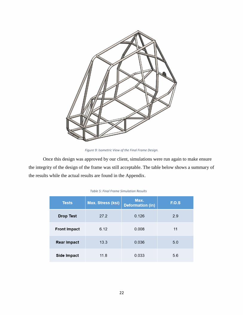
below in Figure 9.
22
Figure 9: Isometric View of the Final Frame Design.
Once this design was approved by our client, simulations were run again to make ensure
the integrity of the design of the frame was still acceptable. The table below shows a summary of
the results while the actual results are found in the Appendix.
Table 5: Final Frame Simulation Results

23
Bill of Materials
In order to determine a budget for building the baja vehicle, the baja frame team created a
list of materials that was broken up into two categories; raw materials and commercial. Each list
contains the material, the quantity, and cost of the materials. The following table show the list of
materials for the raw materials need for building the frame.
AISI 4130 steel tubing with a diameter of 1.25 in. and wall thickness of 0.065 in. is used
to construct the main members of the frame. The AISI 4130 steel tubing with a diameter of 1 in.
and wall thickness of 0.056 in. will be used to construct the secondary members of the frame. In
addition, 0.375x6 (in) AISI 1018 steel plating is used for making the tabs for panels and
attaching the suspension. Sheet metal is going to be used to build the required fire wall on the
frame. Plastic sheeting is needed to be purchased, so the frame team can build the driver seat and
make body panels for the frame. Thus, in order to make the mentioned parts, the frame team is
going to purchase a 2x3 ft. plastic sheeting. The PVC piping is going to be used to build a
dimensional prototype of the frame. This will allow the team to check dimensions and/or change
dimension based on the size of the drivers. All of these mentioned materials are the required raw
materials for our frame design. The total cost of the needed raw materials to be purchased to
build the baja frame came out to be $915. The following table shows the commercial parts that
will be purchased for safety of the driver.
Table 6: List of Raw Materials for building the frame.

24
All of the materials listed above are required for participating in the SAE competition. If
the team is missing any of the items, the team would not be able to compete making this a non-
negotiable budget of $385.
Table 8 shows when adding the total cost for the needed raw materials and commercial
parts together, the entire cost of the frame is $1,300. Since there was no exact limitation on the
cost to build the frame, this cost is deemed acceptable. One thing that has not been added to this
list is the material that will be donated. As of now, all of the tubing from the raw materials table
will be donated. This will cut the budget to $510, making the frame cheaper than the previous
frame team’s assumed budget of $715.
Table 7: List of Commercial Parts need to compete.
Table 8: Total Budget of the frame.

25
Conclusion
The frame team task was to design and build a Mini Baja frame that would outperform
the last year’s baja vehicle. After examining the previous vehicle, and communicating with the
client, the team started designing various concepts that would be light in weight but still have a
large amount of strength. After comparing concepts, two design were chosen to perform a FAE
analysis on. From the results of the analysis, the Front Bracing Frame was chosen as the base
design to alter into a finalized design. After communicating with Dr. Tester and the other teams,
the frame was then modified to incorporate the designs of the suspension and drivetrain. This led
to a finalized version of the frame that is 70lbs and yields a factor of safety of 2.7 if the frame
was to fall upside down from 10ft. The projected cost of the frame and safety equipment was a
total cost of $1,300. The next step is to order and complete the build of the frame by the middle
of January, finish the vehicle by the end of February, start testing in March, and go to
competition in May.

26
References
[1] Dr. John Tester
[2] K. Nam-Ho, “Introduction to Finite Element Analysis and Design” 2008, Wiley.
[3] SAE International, “2015 Collegiate Design Series Baja SAE Rules” 2014, 2014.
[4] A. T. Owens, "Structural considerations of a Baja SAE frame," 2006-12-05, 2006.
[5] NAU SAE Baja 2013-2014
[6] http://www.youtube.com/watch?v=gAwVya8AfyM
[7] SAE Design and Analysis Project with SolidWorks Software
[8] SAE Mini Baja Frame Analysis 2013
[9]. http://www.superatv.com/Polaris-Ranger-XP-900-6-Lift-Kit-P8182.aspx, access 2014.
[10]. http://socalbajas.com/, access 2014.
[11]. 2015 Collegiate Design Series Baja SAE Rules

27
Appendix
Figure 10: Front Supporting Deformation Simulation Results from Drop Test.
Figure 11: Front Supporting Stress Simulation Results from Drop Test.

28
Figure 12: Front Supporting Deformation Simulation Results from Front Impact Test.
Figure 13: Front Supporting Stress Simulation Results from Front Impact Test.

29
Figure 14: Front Supporting Deformation Simulation Results from Rear Impact Test.
Figure 15: Front Supporting Stress Simulation Results from Rear Impact Test.

30
Figure 16: Front Supporting Deformation Simulation Results from Side Impacting Test.
Figure 17: Front Supporting Deformation Simulation Results from Side Impacting Test.
31
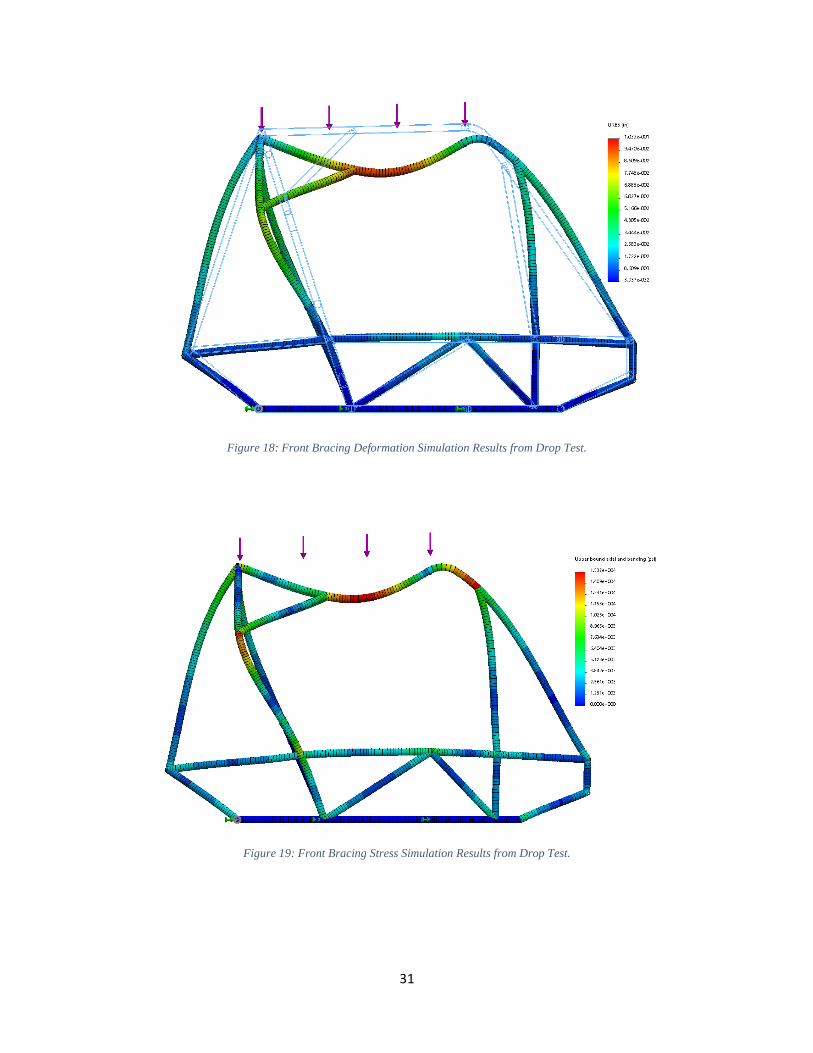
Figure 18: Front Bracing Deformation Simulation Results from Drop Test.
Figure 19: Front Bracing Stress Simulation Results from Drop Test.

32
Figure 20: Front Bracing Deformation Simulation Results from Front Impact Test.
Figure 21: Front Bracing Stress Simulation Results from Front Impact Test.

33
Figure 22: Front Bracing Deformation Simulation Results from Rear Impact Test.
Figure 23: Front Bracing Stress Simulation from Rear Impact Test.

34
Figure 24: Front Bracing Deformation Simulation Results from Side Impact Test.
Figure 25: Front Bracing Stress Simulation Results form Side Impact Test.

35
Figure 26: Final Design Deformation Simulation Results from Drop Test.
Figure 27: Final Design Stress Simulation Results from Drop Test.
36
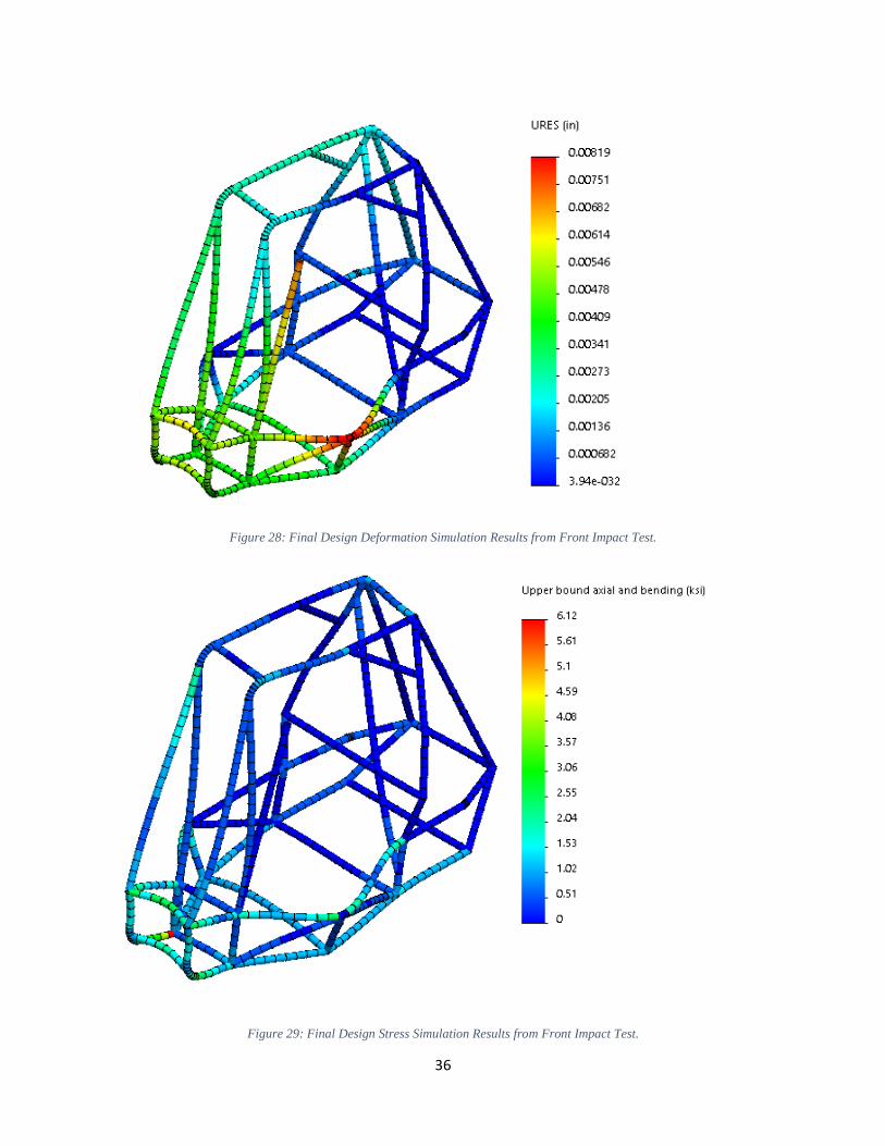
Figure 28: Final Design Deformation Simulation Results from Front Impact Test.
Figure 29: Final Design Stress Simulation Results from Front Impact Test.
37
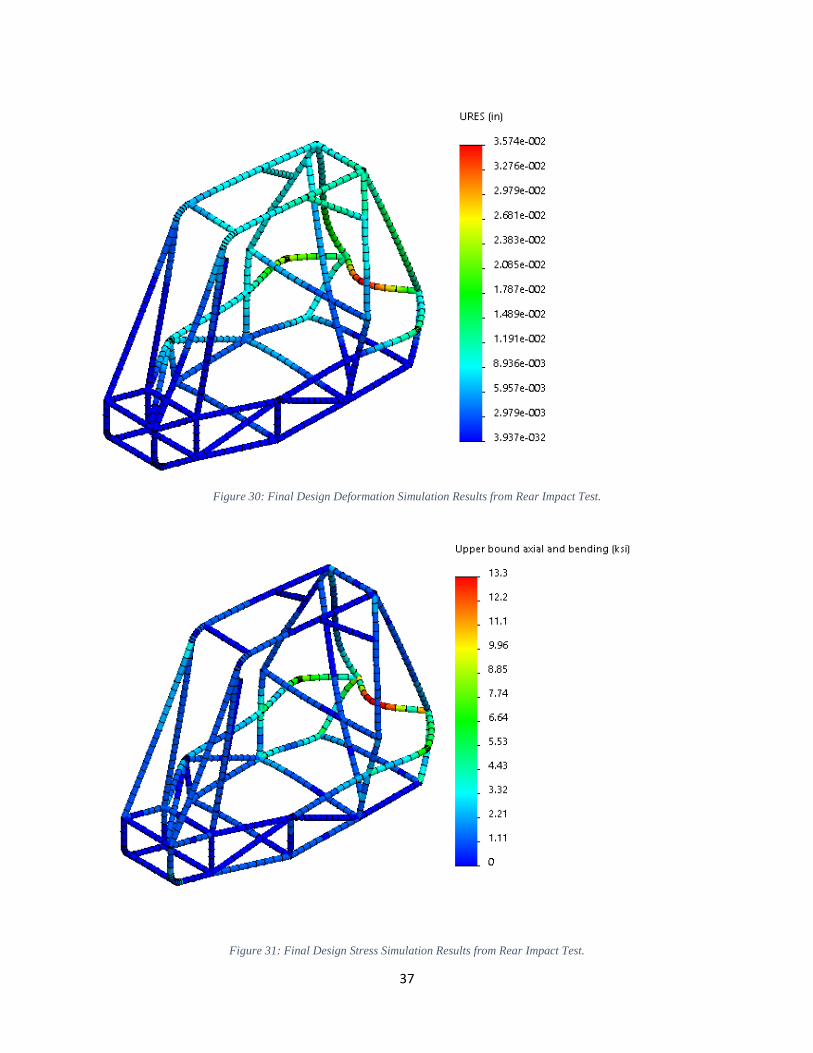
Figure 30: Final Design Deformation Simulation Results from Rear Impact Test.
Figure 31: Final Design Stress Simulation Results from Rear Impact Test.

38
Figure 32: Final Design Deformation Simulation Results from Side Impact Test.
Figure 33: Final Design Stress Simulation Results from Side Impact Test.