sace isomax s - abb grouppalanca de maniobra con tornillos y arandelas de fijación grupo de...
TRANSCRIPT

COMANDO A MANIGLIA ROTANTE NORMALE O DI EMERGENZA A DISTANZA FISSA SU PORTA DELLA CELLA (*)FIXED DEPTH ROTARY NORMAL OR EMERGENCY HANDLE OPERATING MECHANISM FOR COMPARTMENT DOOR (*)NORMALER ODER NOT-DREHHEBELANTRIEB MIT FESTEM ABSTAND AUF DER LEISTUNGSSCHALTERFELDTÜR (*)
COMMANDE PAR POIGNEE ROTATIVE NORMALE OU D’URGENCE SUR LA PORTE DU COMPARTIMENT A DISTANCE FIXE (*)SISTEMA DE MANDO CON MANIJA GIRATORIA NORMAL O DE EMERGENCIA A DISTANCIA FIJA EN LA PUERTA DE LA CELDA (*)
SACE S1 SACE S2
ABB SACE
QUANTITÀQUANTITYANZAHLQUANTITECANTIDAD
1
1
1
2
2
CONTENUTO
Leva dimanovra conviti e rosettedi fissaggio
Gruppo dimanovra
Dima diforatura perporta dellacella
Vite M4x60
Rosette perviti (4)
POS.ITEMPOS.POS.ART.
1
2
3
4
5
CONTENTS
Rotary handlemechanismwith fixingscrews andwashers
Operatingmechanism
Compartmentdoor drilling template
M4x60 screw
Washers forscrews (4)
INHALT
SchalthebelmitBefestigungs-schrauben undScheiben
Schaltwerk
Bohrschablonefür dieSchaltfeldtür
SchraubeM4x60
Unterleg-scheiben fürSchrauben (4)
CONTENU
Levier demanouvreavec vis etrondelles defixation
Groupe demanoeuvre
Gabarit deperçage pourla porte ducompartiment
Vis M4x60
Rondellespour vis (4)
CONTENIDO
Palanca demaniobra contornillos yarandelas defijación
Grupo demaniobra
Plantilla paraperforar lapuerta de lacelda
Tornillo M4x60
Arandelaspara tornillos(4)
(*) con possibilità di accessori per comando a maniglia rotante a distanza regolabile.(*) with option of accessories for adjustable depth crank handle operating mechanism.(*) Ausstattung mit Zubehör für den Drehhebelantrieb mit einstellbarem Abstand möglich.(*) avec possibilité d’accessoires pour commande par poignée rotative à distance réglable.(*) con posibilidad de accesorios para mando giratorio para distancia regulable.
Comando con blocco porta e blocco alucchetti (max 3 lucchetti Ø 6 mm a curadel Cliente)
Operating mechanism with door interlockand padlock device (max. three 6 mmgauge padlocks, to be provided by cus-tomer)
Antrieb mit Türverriegelung und Schloßver-riegelung (max 3 Hängeschlösser von 6mm Ø vom Kunden beizustellen)
Commande avec verrouillage porte etverrouillage par cadenas (max 3 cadenasde Ø 6 mm aux soins du client)
Sistema de mando con bloqueo de lapuerta y cierre con candados (máx. 3candados de 6 mm de Ø, por cuenta delcliente)
5
1
2
3
4
KIT A
SACE Isomax S
KIT 601778/064 L0454

2
ISTRUZIONI INSTRUCTIONS ANWEISUNGEN INSTRUCTIONS INSTRUCCIONES
Accessorio per comando a manigliarotante per distanza regolabile fino a300 mm (min 168 mm).
QUANTITÀQUANTITYANZAHLQUANTITECANTIDAD
1
1
3
3
3
CONTENUTO
Asta di rinvio
Giunto
Vite M4x20
Rosetta
Dado M4
POS.ITEMPOS.POS.ART.
6
7
8
9
10
INHALT
Übertragungsstab
Kupplung
Schraube M4x20
Unterlegscheibe
Mutter M4
CONTENU
Tige de renvoi
Joint
Vis M4x20
Rondelle
Ecrou M4
CONTENIDO
Varilla de transmisión
Junta
Tornillo M4x20
Arandela
Tuerca M4
Accessorio per comando a maniglia ro-tante per distanza regolabile fino a 621,5mm (min 340 mm).
QUANTITÀQUANTITYANZAHLQUANTITECANTIDAD
1
3
6
3
1
3
1
CONTENUTO
Giunto
Vite M4x20
Rosetta
Dado M4
Asta di rinvio
Vite M4x6
Supporto
POS.ITEMPOS.POS.ART.
7
8
9
10
11
12
13
CONTENTS
Coupling
M4x20 screw
Washer
M4 nut
Transmission rod
M4x6 screw
Support
INHALT
Kupplung
Schraube M4x20
Unterlegscheibe
Mutter M4
Übertragungsstab
Schraube M4x6
Stütze
CONTENU
Joint
Vis M4x20
Rondelle
Ecrou M4
Tige de renvoi
Vis M4x6
Support
CONTENIDO
Junta
Tornillo M4x20
Arandela
Tuerca M4
Varilla de transmisión
Tornillo M4x6
Soporte
CONTENTS
Transmission rod
Coupling
M4x20 screw
Washer
M4 nut
Accessory for crank handle operatingmechanism for adjustable depth up to300 mm (min. 168 mm).
Accessory for crank handle operatingmechanism for adjustable depth up to621.5 mm (min. 340 mm).
Zubehör für Drehhebelantrieb mit ein-stellbarem Abstand bis 300 mm (Min.168 mm).
Accessoire pour commande par poignéerotative pour distance réglable jusqu’à300 mm (min. 168 mm).
Accesorio para mando giratorio paradistancia regulable hasta 300 mm (min.168 mm).
Zubehör für Drehhebelantrieb mit ein-stellbarem Abstand bis 621,5 mm (Min.340 mm).
Accessoire pour commande par poignéerotative pour distance réglable jusqu’à621,5 mm (min. 340 mm).
Accesorio para mando giratorio paradistancia regulable hasta 621,5 mm (min.340 mm).
11
7
12
9
8 9
13
9
12
Accessorio CAccessory CZubehör CAccessoire CAccesorio C
10
6
7
8
9
10
Accessorio BAccessory BZubehör BAccessoire BAccesorio B

3
ISTRUZIONI INSTRUCTIONS ANWEISUNGEN INSTRUCTIONS INSTRUCCIONES
a Distanza fissa (KIT A)
b Distanza regolabile 168 ÷ 300 mm(KIT A + Accessorio B)
c Distanza regolabile 340 ÷ 621,5 mm(KIT A + Accessorio C)
Disposizione delle esecuzioni
a
b
c
Layout of the versions
a Fixed distance (KIT A)
b 168 ÷ 300 mm adjustable distance(KIT A + Accessory B)
c 340 ÷ 621.5 mm adjustable distance(KIT A + Accessory C)
a Fester Abstand (SATZ A)
b Einstellbarer Abstand 168 ÷ 300 mm(SATZ A + Zubehörteil B)
c Einstellbarer Abstand 340 ÷ 621,5mm (SATZ A + Zubehörteil C)
Anordnung der Ausführungen Disposition des versions
a Distance fixe (KIT A)
b Distance régable 168 à 300 mm(KIT A + Accessoire B)
c Distance régable 340 à 621,5 mm(KIT A + Accessoire C)
a Distancia fija (KIT A)
b Distancia regulable 168 ÷ 300 mm(KIT A + Accesorio B)
c Distancia regulable 340 ÷ 621,5 mm(KIT A + Accesorio C)
Disposición de las ejecuciones

4
ISTRUZIONI INSTRUCTIONS ANWEISUNGEN INSTRUCTIONS INSTRUCCIONES
14 15
16
Foratura della porta della cella
14
Hole drilled in compartment door Bohrungen in der Schaltfeldtür Perçage de la porte du compartiment Taladrado de la puerta de la celda.
Distanza minima dall’asse di rotazionedella porta
15
Minimum distance from axis of door hinge Mindestabstand zur Türdrehachse Distance minimale de l’axe de rotation dela porte
Distancia mínima entre el eje de rotacióny la puerta.
Blocco a lucchetti. Max. 3 lucchetti diam.max. 6 mm (non forniti).
16
Padlock: max. 3 padlocks max Ø 6 mm (notincluded in the supply).
Schloßverriegelung. Max. 3 Vorhänge-schlösser Ø max. 6 mm (nicht im Lierer-umfang eingeschlossen).
Verrouillage par cadenas, au maximum 3cadenas Ø 6 mm maxi (ne sont pas partiede la fourniture).
Bloqueo por candados. Máx. 3 candadosdiám. máx. 6 mm (no se incluyen en elsuministro).
* Nel caso sia previsto il grado di protezione IP54 * If a protection level of IP54 is required * Falls Schutzart IP54 vorgesehen ist. * Dans le cas où le degré de protection IP54 seraitprévu.
* En el caso de que se haya previsto el grado deprotecciòn IP54.
Distanza fissa
A
A
14
15
16
14
15
16
14
15
16
14
15
16
Fixed distanceA Fester AbstandA Distance fixeA Distancia fijaA

5
ISTRUZIONI INSTRUCTIONS ANWEISUNGEN INSTRUCTIONS INSTRUCCIONES
B
Mettere una goccia di vernice sulla puntadell’asta di rinvio. Verificare che sia per-pendicolare al piano del coperchio dell’in-terruttore e chiudere la porta della cella.Eseguire sulla porta un foro diametro 33mm con centro nel punto marcato dallavernice.
Apply a dab of paint to the tip of theoperating rod. Make sure that the rod isperpendicular to the circuit-breaker coverand close the compartment door so thatthe door is marked by the wet paint. Drill a33 mm diameter hole in the door with thespot marked by the paint at its centre.
Einen Lacktropfen auf die Spitze derÜbertragungsstange setzen. Prüfen, obdiese auf die Schalterdeckelebene senk-recht ist, und die Schaltfeldtür schliessen.In der Tür ein Loch von 33 mm Durchmes-ser mit Zentrum in dem durch den Lackgezeichneten Punkt bohren.
Mettre une goutte de peinture sur la pointede la tige de renvoi. Vérifier qu’elle soitperpendiculaire au plan du couvercle dudisjoncteur et fermer la porte du compar-timent. Effectuer sur la porte un trou de 33mm de diamètre dont le centre est le pointmarqué par la peinture.
Ouvrir le disjoncteur. Enlever les deux visqui fixent le couvercle à la boîte et quiseront remplacées par les vis (4).Appliquer le groupe de manoeuvre (2) surle couvercle du disjoncteur et le fixer àl’aide des vis (4) et des rondelles (5).
Set the circuit-breaker open. Remove thetwo screws fixing the cover to the case.These will be replaced by screws (4) in thekit.Fix the operating mechanism (2) to thecircuit-breaker cover with screws (4) andwashers (5).
Aprire l’interruttore. Eliminare le due vitiche fissano il coperchio alla scatola e cheverranno sostituite dalle viti (4).Applicare al coperchio dell’interruttore ilgruppo di manovra (2) e fissarlo mediantele viti (4) e le rosette (5).
Den Leistungsschalter ausschalten. Be-seitigen die zwei Schrauben, die den Dek-kel mit dem Gehäuse sichern und die vonden Schrauben (4) ersetzt werden.Das Schaltwerk (2) auf den Leistungs-schalterdeckel montieren und mittels derSchrauben (4) und der Unterlegscheiben(5) befestigen.
C
Abrir el interruptor. Extraer los dos torni-llos que aseguran la tapa a la caja, los queserán sustituidos por los tornillos (4).Aplicar a la tapa del interruptor el grupo demaniobra (2) y fijarlo mediante los torni-llos (4) y las arandelas (5).
Aplicar una gota de pintura en la punta dela varilla de reenvío, controlar que quedeperpendicular al plano de la tapa del inte-rruptor y cerrar la puerta de la celda.Practicar en la puerta un orificio de 33 mmde diámetro, con el centro en el puntomarcado con pintura.
2
5
4
Fissaggio gruppo di manovraB
Foratura porta della cellaC
Fixing switching groupB
Drilling of compartment doorC
Befestigung der Bedienungs-einheit
B
Bohrung der SchaltfeldtürC
Fixation groupe de manoeu-vre
B
Perçage porte du comparti-ment
C
Sujeción grupo de maniobraB
Taladrado de la puerta de lacelda
C
6
ISTRUZIONI INSTRUCTIONS ANWEISUNGEN INSTRUCTIONS INSTRUCCIONES
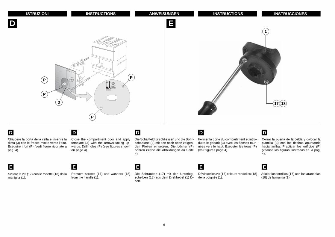
E
E
Remove screws (17) and washers (18)from the handle (1).
Die Schrauben (17) mit den Unterleg-scheiben (18) aus dem Drehhebel (1) lö-sen.
Dévisser les vis (17) et leurs rondelles (18)de la poignée (1).
Svitare le viti (17) con le rosette (18) dallamaniglia (1).
E E E E EAflojar los tornillos (17) con las arandelas(18) de la manija (1).
1
17 18
D
P
P
3
Chiudere la porta della cella e inserire ladima (3) con le frecce rivolte verso l’alto.Eseguire i fori (P) (vedi figure riportate apag. 4).
Close the compartment door and applytemplate (3) with the arrows facing up-wards. Drill holes (P) (see figures shownon page 4).
Die Schaltfeldtür schliessen und die Bohr-schablone (3) mit den nach oben zeigen-den Pfeilen einsetzen. Die Löcher (P)bohren (siehe die Abbildungen au Seite4).
D D D D DFermer la porte du compartiment et intro-duire le gabarit (3) avec les flèches tour-nées vers le haut. Exécuter les trous (P)(voir figures page 4).
Cerrar la puerta de la celda y colocar laplantilla (3) con las flechas apuntandohacia arriba. Practicar los orificios (P)(véanse las figuras ilustradas en la pág.4).
P
P

7
ISTRUZIONI INSTRUCTIONS ANWEISUNGEN INSTRUCTIONS INSTRUCCIONES
F G
G
Positions de la poignée rotative
“ I ” - disjoncteur fermé“O” - disjoncteur ouvert“a” - disjoncteur déclenché.
Dans ce cas, pour refermer le dis-joncteur placer le levier en position“O” puis en “I”.
Posizioni della maniglia rotante
“I” - interruttore chiuso“O” - interruttore aperto“a” - interruttore aperto per intervento
sganciatori.In questo caso per richiudere l’in-terruttore portare la maniglia in “O”e poi in “I”.
Rotary handle positions
“I” - circuit-breaker closed“O” - circuit-breaker open“a” - circuit-breaker tripped by release.
To re-close the circuit-breakerfrom this position, move the han-dle to position “O” first and then toposition “I”.
Stellungen des Drehhebels
“I” - Leistungsschalter Ein“O” - Leistungsschalter Aus“a” - Leistungsschalter Ausgelöst.
Zum Wiedereinschalten des Lei-stungsschalters ist der Drehhebelzuerst auf “O”, und dann auf “I” zustellen.
FFixer la poignée (1) à la porte du comparti-ment (côté extérieur de la porte) à l’aide desvis (17) et des rondelles (18).
Fissare la maniglia (1) alla porta della cella(lato esterno della porta) mediante le viti(17) e le rosette (18).
Fix handle (1) to the outside of the compart-ment door using screws (17) and washers(18).
Den Drehhebel (1) an der Schaltfeldtür(Aussenseite der Tür) mittels der Schrau-ben (17) und der Unterlegscheiben (18)befestigen.
Posiciones de la manija giratoria“I” - Interruptor cerrado“O” - Interruptor abierto“a” - Interruptor abierto por intervención
de los relés.En este caso, para volver a cerrar elinterruptor, poner la manija en “O” yluego en “I”.
Fijar la manija (1) a la puerta de la celda (dellado externo) mediante los tornillos (17) ylas arandelas (18).
17 18
1
G
F
G
F
G
F
G
F
a

8
ISTRUZIONI INSTRUCTIONS ANWEISUNGEN INSTRUCTIONS INSTRUCCIONES
H
HPer attivare il blocco a lucchetti ad interrut-tore aperto, spingere la leva (19) dalla partecontrassegnata dal simbolo ( ) e inserirei lucchetti come indicato (massimo 3 luc-chetti - diametro dello stelo 6 mm - a curadel cliente).
To lock the padlock device with the circuit-breaker open, push lever down (19) at the( ) symbol and insert the padlocks asshown (maximum three 6 mm gauge pad-locks to be provided by customer).
Zum Aktivieren der Schlossverriegelungbei ausgeschaltetem Leistungsschalter istder Hebel (19) an der mit dem Symbol ( )gekennzeichneten Seite hineinzudrückenund sind die Vorhänge-schlösser, wie an-gezeigt, einzusetzen (höchstens 3 Vorhän-ge-schlösser - Bügel von 6 mm Durchmes-ser - vom Kunden beizustellen).
Pour activer le verrouillage par cadenas,avec le disjoncteur ouvert, pousser le levier(19) sur la partie reperée par le symbole( ) et placer les cadenas comme indiqué(3 cadenas au maximum -diamètre de l’ar-ceau 6 mm - aux soins du client).
Blocco a lucchetti
Padlock deviceSchlossverriegelungVerrouillage par cadenasCierre con candado
H H H HPara activar el cierre con candados cuandoel interruptor está abierto, empujar la palan-ca (19) por la parte marcada con el símbolo( ) y colocar los candados según las indi-caciones (como máximo, 3 candados - diá-metro del vástago 6 mm - por cuenta delcliente).
19

9
ISTRUZIONI INSTRUCTIONS ANWEISUNGEN INSTRUCTIONS INSTRUCCIONES
I
Sblocco della porta della cella ad interruttore chiusoEmergency release device to open compartment door with circuit-breaker closedEntriegelung der Schaltfeldtür bei eingeschaltetem Leistungsschalter
Déblocage de la porte du compartiment avec disjoncteur ferméDesbloqueo de la puerta de la celda con el interruptor cerrado
I
La poignée est conçue de telle façon quesi le disjoncteur est fermé, la porte ducompartiment ne peut pas être ouverte. Sil’ouverture était nécessaire (seulementen cas d’urgence), pousser une tige dansle trou latéral indiqué sur la figure et ouvrirla porte en même temps.
La maniglia è progettata in modo che coninterruttore chiuso, è impedita l’aperturadella porta della cella. Qualora l’aperturasi renda necessaria (solo in caso di emer-genza), premere mediante un’astina (dia-metro massimo 5 mm) nel foro lateraleindicato in figura e contemporaneamenteaprire la portella.
The rotary handle is designed so that thecompartment door cannot be opened whenthe circuit-breaker is closed. If the doorhas to be opened in an emergency, pusha rod (max. diameter 5 mm) into the holein the side as shown in the figure, andopen the door.
Der Drehhebel ist so ausgelegt, dass dieÖffnung der Schaltfeldtür bei eingeschal-tetem Leistungsschalter verhindert ist.Sollte es notwendig sein, die Tür (nur imNotfall) zu öffnen, ist ein Stäbchen(grösster Durchmesser 5 mm) in das seit-liche Loch, wie in Abbildung angezeigt,hineinzudrücken und die Tür gleichzeitigzu öffnen.
I I I I
La manija está proyectada de manera quecon el interruptor cerrado no se puedaabrir la puerta de la celda. Si es necesarioabrirla (sólo en caso de emergencia),hacer presión con una varilla (de 5 mm dediámetro como máximo) sobre el orificiolateral que se muestra en la figura y, almismo tiempo, abrir la puerta.

10
ISTRUZIONI INSTRUCTIONS ANWEISUNGEN INSTRUCTIONS INSTRUCCIONES
F 7E
8 6
16
– Per il montaggio del gruppo di manovravedi pag. 5; nota B.
– Montare a fondo il giunto (7) sull'albero(E).
– Montare le viti, le rosette e dadi (8) (9)(10) e stringere a fondo solo la vite (F).
– Tagliare l'asta di rinvio (6) (quota L) aseconda della profondità di installazione(A) seguendo la regola L = (A+B) –137,5 mm.
– Montare l'asta di rinvio (6) sul giunto estringere a fondo le restanti viti.
– Per la foratura della porta cella vedipag. 4÷6.
– Blocco a lucchetti. Max 3 lucchetti Ømax 6 mm (16) (non forniti).
– For assembly of the switching group,see page 5 note B.
– Fit the joint (7) all the way onto the shaft(E).
– Fit the screws, washers and nuts (8) (9)(10) and only tighten screw (F) fullyhome.
– Cut the transmission rod (6) (distance L)according to the depth of installation (A)following the rule L = (A+B) – 137.5 mm.
– Mount the transmission rod (6) on cou-pling and fully tighten the remainingscrews.
– For drilling of compartment door, seepages 4÷6.
– Padlock: max. 3 padlocks max Ø 6 mm(16)(not included in the supply).
A min.= 168 mm
A max = 300 mmB = 18 mm normale fornitura
A max = 298 mmB = 20 mm con grado di protezione IP54
A min.= 168 mm
A max = 300 mmB = 18 mm normal supply
A max = 298 mmB = 20 mm with protection level IP54
A min.= 168 mm
A max = 300 mmB = 18 mm normale Lieferung
A max = 298 mmB = 20 mm mit Schutzart IP54
A min.= 168 mm
A max = 300 mmB = 18 mm fourniture normale
A max = 298 mmB = 20 mm avec degrés de protection IP54
A min.= 168 mm
A máx = 300 mmB = 18 mm suministro normal
A máx = 298 mmB = 20 con grado de protección IP54
– Für die Montage der Bedienungseinheitsiehe Seite 5; Anm. B.
– Kupplung (7) bis zum Anschlag auf Wel-le (E) montieren.
– Die Schrauben, Beilagscheiben und Mut-tern (8) (9) und (10) montieren und nurSchraube (F) fest anziehen.
– Den Übertragungsstab (6) (Maß L) jenach Einbautiefe (A) nach der GleichungL= (A+B) –137,5 mm zuschneiden.
– Den Übertragungsstab (6) auf die Kupp-lung bauen und die verbleibendenSchrauben fest anziehen.
– Für die Bohrung der Schaltfeldtür sieheSeite 4÷6.
– Schloßverriegelung max. 3 Vorhänge-schlösser Ø max. 6 mm (16)(nicht imLiererumfang eingeschlossen).
– Pour le montage du groupe de manoeu-vre, voir page 5, note B
– Monter à fond le joint (7) sur l’arbre (E).– Monter les vis, les rondelles et les écrous
(8) (9) (10) et ne serrer à fond que la vis(F).
– Couper la tige de renvoi (6) (dimension L)en fonction de la profondeur d’installation(A) en appliquant la règle L= (A+B) –137,5 mm.
– Monter la tige de renvoi (6) sur le joint etserrer à fond les vis restantes.
– Pour le perçage de la porte du compar-timent, voir pages 4÷6.
– Verrouillage par cadenas, au maximum3 cadenas Ø 6 mm maxi (16)(ne sont paspartie de la fourniture).
– Para montar el grupo de maniobra, véa-se pág. 5, nota B.
– Montar hasta el fondo la junta (7) en eleje (E).
– Montar los tornillos las arandelas y lastuercas (8) (9) (10) y apretar sólo eltornillo hasta el fondo (F).
– Cortar la varilla de transmisión (6) (cotaL) según la profundidad de instalación(A) aplicando la regla L= (A+B) –137,5mm.
– Montar la varilla de transmisión (6) en lajunta y apretar hasta el fondo los demástornillos.
– Para el taladrado de la puerta de la celdavéanse las páginas 4÷6.
– Bloqueo por candados máx. 3 candadosØ máx 6 mm (16)(no se incluyen en elsuministro).
L
L
Distanza regolabile 168 ÷ 300 mm
168 ÷ 300 mm adjustable distanceEinstellbarerAbstand 168 ÷ 300 mmDistance réglable 168 ÷ 300 mmDistancia regulable 168 ÷ 300 mm
L L L L

11
ISTRUZIONI INSTRUCTIONS ANWEISUNGEN INSTRUCTIONS INSTRUCCIONES
– Per il montaggio del gruppo di manovravedi pag. 5; nota B.
– Per il montaggio del giunto vedi pag. 10;nota L.
– Montare il supporto (13) fissandolo conviti, rosette e dadi (12) (9) curandol'ortogonalità.
– Tagliare l'asta di rinvio (11) (quota L) aseconda della profondità di installazio-ne seguendo la regola L=(A+B)–137,5mm.
– Montare l'asta di rinvio (11) sul giunto(7) e stringere a fondo le restanti viti.
– Per la foratura della porta della cellavedi pag. 4÷ 6.
– Blocco a lucchetti. Max 3 lucchetti Ømax 6 mm (16) (non forniti).
F 7
E 8
13 16
11
12 9
– For assembly of the switching group,see page 5 note B.
– For assembly of the joint, see page 10note L.
– Fit the support (13), fixing it in place withscrews, washers and nuts (12) (9), tak-ing care to ensure it is at right angles.
– Cut the transmission rod (11) (distanceL) according to the depth of installationfollowing the rule L = (A+B) – 137.5 mm.
– Mount the transmission rod (11) on cou-pling (7) and fully tighten the remainingscrews.
– For drilling of compartment door, seepages 4÷6.
– Padlock: max. 3 padlocks max Ø 6 mm(16)(not included in the supply).
A = min. 340
A max = 621,5 mmB = 18 mm normale fornitura
A max = 619,5 mmB = 20 mm con grado di protezione IP54
A = min. 340
A max = 621,5 mmB = 18 mm normal supply
A max = 619,5 mmB = 20 mm with protection level IP54
– Für die Montage der Bedienungseinheitsiehe Seite 5; Anm. B.
– Für die Montage der Kupplung sieheSeite 10 Anm. L.
– Die Halterung mit den Schrauben (13),Beilagscheiben und Muttern (12) (9) undeinbauen; auf Rechtwinkligkeit achten.
– Den Übertragungsstab (11) (Maß L) jenach Einbautiefe nach der Gleichung L=(A+B) –137,5 mm zuschneiden.
– Den Übertragungsstab (11) auf die Kupp-lung (7) bauen und die verbleibendenSchrauben fest anziehen.
– Für die Bohrung der Schaltfeldtür sieheSeite 4÷6.
– Schloßverriegelung max. 3 Vorhänge-schlösser Ø max. 6 mm (16)(nicht imLiererumfang eingeschlossen).
– Pour le montage du groupe de manoeu-vre, voir page 5, note B
– Pour le montage du joint, voir page 10,note L.
– Monter le support (13) en le fixant avecles vis, rondelles et écrous (12) (9) enfaisant attention à l’orthogonalité.
– Couper la tige de renvoi (11) (dimensionL) en fonction de la profondeur d’instal-lation en appliquant la règle L= (A+B) –137,5 mm.
– Monter la tige de renvoi (11) sur le joint(7) et serrer à fond les vis restantes.
– Pour le perçage de la porte du compar-timent, voir pages 4÷6.
– Verrouillage par cadenas, au maximum3 cadenas Ø 6 mm maxi (16)(ne sont paspartie de la fourniture).
– Para montar el grupo de maniobra, véa-se pág. 5, nota B.
– Para montar la junta, véase pág. 10,nota L.
– Montar el soporte (13) sujetándolo conlos tornillos, las arandelas y las tuercas(12) (9) prestando atención a la ortogo-nalidad.
– Cortar la varilla de transmisión (11) (cotaL) según la profundidad de instalaciónaplicando la regla L= (A+B) –137,5 mm.
– Montar la varilla de transmisión (11) enla junta (7) y apretar hasta el fondo losdemás tornillos.
– Para el taladrado de la puerta de la celdavéanse las páginas 4÷6.
– Bloqueo por candados máx. 3 candadosØ máx 6 mm (16)(no se incluyen en elsuministro).
A = min. 340
A max = 621,5 mmB = 18 mm normale Lieferung
A = max 619,5B = 20 mm mit Schutzart IP54
A = min. 340
A max = 621,5 mmB = 18 mm fourniture normale
A max = 619,5 mmB = 20 mm avec degré de protection IP54
A = min. 340
A màx = 621,5 mmB = 18 mm suministro normal
A max = 619,5 mmB = 20 mm con grado de protección IP54
Distanza regolabile 340 ÷ 621,5 mm
340 ÷ 621.5 mm adjustable distanceEinstellbarerAbstand 340 ÷ 621,5 mmDistance réglable 340 ÷ 621,5 mmDistancia regulable 340 ÷ 621,5 mm
M
M M M M M

ABB SACE S.p.AL.V. Breakers DivisionVia Baioni, 35 - 24123 Bergamo - ItalyTel.: +39 035.395.111 - Telefax: +39 035.395.306-433http://www.abb.com
Due to possible developments of standards as well as of materials,the characteristics and dimensions specified in the present cataloguemay only be considered binding after confirmation by ABB SACE.