sa roofing may 2015 | issue: 69
DESCRIPTION
SA Roofing is the only publication in South Africa that is dedicated exclusively to the residential, commercial and industrial roofing and re-roofing industries.TRANSCRIPT

MAY 2015 ISSUE: 69WWW.TRADEMAX.CO.ZA SA R36 EACH INCL. / R360 PER ANNUM INCL.
EMISSIONS TEST CERTIFICATE
EMISSIONS TEST CERTIFICATE


MAY 2015 ISSUE: 69
EDITOR’S COMMENTS ...................................................................................................... 2
CONTRIBUTORS ................................................................................................................ 4
METAL CLADDING .................................................................................................... 10-12
FIRE TESTING ................................................................................................................ 14-18
LEGISLATION ............................................................................................................... 22-27
METAL SHEETING ....................................................................................................... 30-32
ASPHALT ROOF SHINGLES ..................................................................................... 34-36
TIMBER TRUSSES .......................................................................................................... 38-41
STEEL ............................................................................................................................... 42-44
TRUSSES ......................................................................................................................... 46-48
EXPANDED POLYSTYRENE ..................................................................................... 50-52
10 34
38
MAY 2015
34
Trademax Publications
SA Roofing
Tel: 0861 SA ROOF Tel: 0861 727 663 Fax: 0866 991 346
Email: [email protected]
www.trademax.co.za
Postnet Suite 241
Private Bag X103
N1 City
7463 PUBLISHER: Billy Perrin
082 266 6976
EDITOR: Jennifer Rees
ADVERTISING: Jacqui Marsh
LAYOUT & DESIGN: Craig Patterson
SUBSCRIPTIONS: Belinda Thwesha
DISCLAIMERThe views expressed herein are not necessarily those of Trademax Publications. Although we have done our best to ensure the accuracy of our content, neither Trademax Publications nor SA Roofing magazine will be held liable for any views expressed or information disseminated, in
editorial content or advertisements, in this issue.
Follow us! Connect with us!Like us!

In this, our May issue, we delve into the history of self-supporting metal cladding with an editorial contribution from the Southern African Metal Cladding and Roofing
Association (SAMCRA), which explores the evolution of cladding right from the age of the crusades to the present day and in the South African context.
With another editorial contribution from Lyndsay Cotton of LCP Roofing, also Chairman on the board of the Institute for Timber Construction South Africa (ITC-SA), we take a look at some of the on-site challenges facing the truss fabricator and erector on site.
Finally, all good things come to an end, as we run the third and last instalment of our series by Doug Michell of the Master Builders Association North on the new construction regulations of 2014. Read this final article, which focuses more closely on the duties of the principal contractor and sub-contractor as they could pertain to the roofing sector on page 22.
As I write this, the much-anticipated TotallyConcrete Expo, African Construction Expo, and Coatings for Africa Symposium and Expo are just around the corner, and we are delighted and proud to be a media partner to these events.
We trust that if you are attending any of these expos, you will have a great show and a wonderful time there. If you won’t be able to make it, don’t despair – keep an eye out for the upcoming June issue of SA Roofing, in which we will be featuring follow-ups on the event happenings. As always, we invite you to write to us with an opinion piece, a letter to the editor, a comment, or suggestions. We also encourage you to connect and engage with us on Facebook, Twitter and LinkedIn.
Welcome to the May issue of the SA Roofing magazine. Enjoy the read!Jen
EDIT
OR
’S C
OM
MEN
TS Eventful
While we are somewhat dismayed by how close we already are to the middle of the year, 2015 still has so much left to offer – not only in terms of great events on the roofing calendar, but another six months’ worth of
exciting, jam-packed editions of SA Roofing.


CO
NT
RIB
UT
OR
S ContributorsLyndsay entered the construction industry in 1989 as a technical assistant at the City Council of Pretoria and graduated in 1992 with BSc (QS) degree. He obtained a Diploma in Project Management shortly thereafter and is the current chairman of and serving on the board of directors for the Institute for Timber Construction (ITC-SA). Lyndsay has constructed well over 300 residential projects (upmarket complexes and ultra luxury individual residential units) and is well versed in residential construction – especially with regards to roofing. He was part of the team that established LCP Roofing in 2010 and the company now boasts, among other achievements, the SANS1900 accreditation for monoplaner prefabricated timber roof trusses (nail plated).
Doug entered into Construction Health and Safety in 1983 and has been involved in numerous major projects representing the client, project managers and contractors, experience that stands him in good stead to provide guidance to members in construction health and safety matters through the project life cycle. Since joining the MBA in 2008 he has served on ACOHS and has been appointed to serve on the Technical Committee for the Construction Regulations and more recently the SACPCMP task team for the development of the registration criteria for Construction Health and Safety Practitioners with the SACPCMP.
Erich is registered as a Professional Materials Scientist at the South African Council of Natural Scientific Professions. He is Senior Manager of Civil and Mechanical Testing as well as Metrology at the South African Bureau of Standards (SABS). He holds a BSc Honours degree, a BSc (Physics) degree, a Diploma in Datametrics, and has been with the SABS for the past 17 years. Previously he worked at the Physics Department of the University of Pretoria. Erich has published several scientific articles and presentations on the testing of building materials. He began his career at Centurion Fire Brigade as a fireman.
LYNDSAY COTTON
DOUG MICHELL
ERICH SEEGER
Upcoming EventsCOATINGS FOR AFRICA SYMPOSIUM & EXPO 11-13 MAY 2015, SANDTON CONVENTION CENTRE, JOHANNESBURG
View www.coatingsforafrica.org.za for more info
WOODEX FOR AFRICA 9-11 JUNE 2016, GALLAGHER CONVENTION CENTRE, JOHANNESBURG
View www.woodexforafrica.com for more info
TOTALLYCONCRETE EXPO 13-14 MAY 2015, SANDTON CONVENTION CENTRE, JOHANNESBURG
View www.totallyconcrete.co.za for more info
CAPE CONSTRUCTION EXPO 12-13 AUGUST 2015, CTICC, CAPE TOWN
View www.cape-construction.co.za for more info
AFRICAN CONSTRUCTION EXPO 13-14 MAY 2015, SANDTON CONVENTION CENTRE, JOHANNESBURG
View www.construction-week.com for more info
Image courtesy: Coatings for Africa
4 MAY 2015

CONTACT: Tel: +27 11 814 1898 | Fax: +27 11 814 2166 | Email: [email protected] | Web: www.jcproofing.co.za
JCP Roofing is a new business that came into existence through JCP STEEL, a company that has been serving the steel industry with flat steel products for over 22 years, with a reputation for excellent service, uncompromising quality and impressive lead times.
We have expanded our portfolioto supply IBR and corrugatedroofing sheets to the same levelof quality and service to whichour customers areaccustomed to.
• IBR• Corrugated• Polycarbonate Sheeting• Bullnosing / Cranking• Flat Sheets• Screws & Fasteners
PRODUCTS:
GRSGLOBAL ROOFING SOLUTIONSGRS Klip-Tite
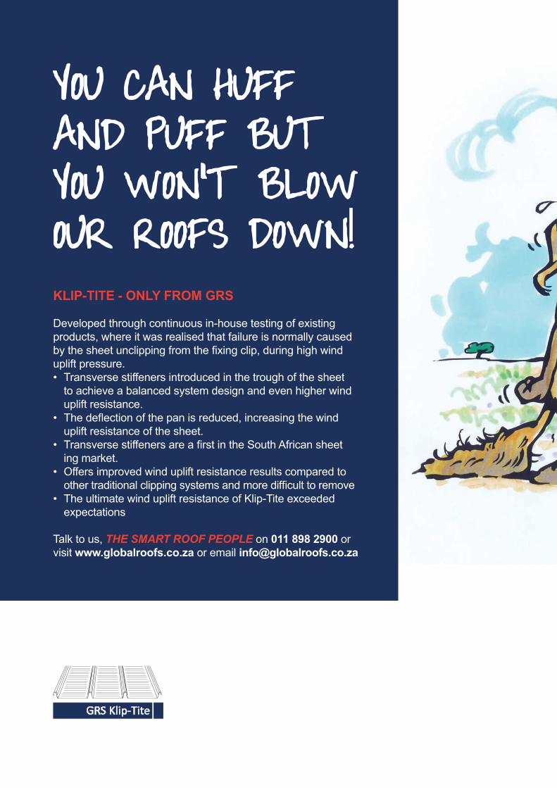
KLIP-TITE - ONLY FROM GRS
Developed through continuous in-house testing of existing products, where it was realised that failure is normally caused by the sheet unclipping from the fi xing clip, during high wind uplift pressure.• Transverse stiffeners introduced in the trough of the sheet to achieve a balanced system design and even higher wind uplift resistance.• The defl ection of the pan is reduced, increasing the wind uplift resistance of the sheet.• Transverse stiffeners are a fi rst in the South African sheet ing market.• Offers improved wind uplift resistance results compared to other traditional clipping systems and more diffi cult to remove• The ultimate wind uplift resistance of Klip-Tite exceeded expectations
Talk to us, THE SMART ROOF PEOPLE on 011 898 2900 or visit www.globalroofs.co.za or email [email protected]
YOU CAN HUFF AND PUFF BUT YOU WON’T BLOWOUR ROOFS DOWN!
0224 GRS Wolfie DPS (297x420).indd 1 2015/01/15 1:30 PM

GRSGLOBAL ROOFING SOLUTIONSGRS Klip-Tite
KLIP-TITE - ONLY FROM GRS
Developed through continuous in-house testing of existing products, where it was realised that failure is normally caused by the sheet unclipping from the fi xing clip, during high wind uplift pressure.• Transverse stiffeners introduced in the trough of the sheet to achieve a balanced system design and even higher wind uplift resistance.• The defl ection of the pan is reduced, increasing the wind uplift resistance of the sheet.• Transverse stiffeners are a fi rst in the South African sheet ing market.• Offers improved wind uplift resistance results compared to other traditional clipping systems and more diffi cult to remove• The ultimate wind uplift resistance of Klip-Tite exceeded expectations
Talk to us, THE SMART ROOF PEOPLE on 011 898 2900 or visit www.globalroofs.co.za or email [email protected]
YOU CAN HUFF AND PUFF BUT YOU WON’T BLOWOUR ROOFS DOWN!
0224 GRS Wolfie DPS (297x420).indd 1 2015/01/15 1:30 PM

EMIS
S IONS T E S T CERT IF ICATE
EMISS IONS T E S T CER TIF IC
ATE


ME
TA
L C
LA
DD
ING
Self-supporting metal cladding
Of all the roofing materials, metal cladding has evolved the most with time. Metal-clad roofs were introduced to Europe during the Crusades and comprised seamed (flat or upright) hand-beaten soft metal sheets
anchored to a timber underlay by concealed cleats.
MAY 201510
There are buildings in Europe with lead and copper roofs that are more than 500 years old and roofs clad with zinc that are 200 years old, which attest to the durability of this form of cladding.
It was, however, exorbitantly expensive.
The industrial revolution saw the introduction of both thin gauge galvanized steel and folding machines, which greatly reduced the cost and made metal cladding a lot more affordable.
At the turn of the previous century, patterned drum rollers capable of forming longitudinal ribs in flat sheets gave the world corrugated iron. This new form of metal cladding was capable of spanning between support members, thereby eliminating the need for decking to support the cladding.
As the profiles facilitated an overlap at the sides, there was no need to mechanically seal the side seams.
This was the first of all the self-supporting metal cladding profiles we are so familiar with today and for the first time, metal cladding became an economical alternative.
Another change was the method of anchoring the cladding to the structure where the concealed cleat was replaced with a ‘nail’ that pierced the profile, i.e. pierced-fix. During World War II the continuous rolling process was invented together with the stronger box-rib profiles such as the ubiquitous IBR and a further innovation was the introduction of aluminium cladding.
During the 1950s a number of profiles with broad pans, standing seams and concealed anchors were introduced under the generic name of concealed fix. Unfortunately these profiles required mechanical seaming of the side laps. Following the development of thin gauge high tensile coated steels in the 1960s, which not only enabled profiles to be rolled from thinner material, its inherent springiness lead to the development of snap-together side laps. On-site milling was also introduced during this period.
Current concealed-fix profiles combine the high water-carrying capacity of broad pans with the strength of trapezoidal box ribs which are ideally suited to flatter roofs. Some profiles are even referred to as decks. On-site milling eliminates the need for end laps which are always problematic, both from a weatherproofing and corrosion point of view.
When selecting a cladding system, i.e. profile, type of anchor and weatherproofing, it is important to match the performance criteria and geometry for the building with those of the cladding system. Important factors are thermal movement, wind loading, slope, drainage capacity, maintenance of the cladding, foot traffic from maintenance of glazing and items of plant located on a roof. In-plane skylights can have a negative impact on the weatherproof performance of both roof and side cladding.
There have also been a number of developments in the durability of the metallic and paint coatings applied to metal cladding. Metallic coatings range from zinc (galvanized) through aluminium/zinc, of various combinations (55%, 5%, etc.) to aluminium and tin. Modern painted coatings not only provide for aesthetics, but also add protection in aggressive and industrially polluted environments. When selecting a protective coating it is important to consider both the macro and micro climatic influences that will impact on the performance of the coating system or metal. Fallout from stacks, venting systems and adjacent industry together with internal process and storage of highly alkaline and other corrosive materials can have a considerably negative impact on the performance of the coating or the metal itself in the case of aluminium and stainless steel.
Of equal importance is the selection of the fasteners. Firstly, they must be capable of transferring all the design loads acting on the cladding to the support structure.
ME
TA
L CL
AD
DIN
G
MAY 2015
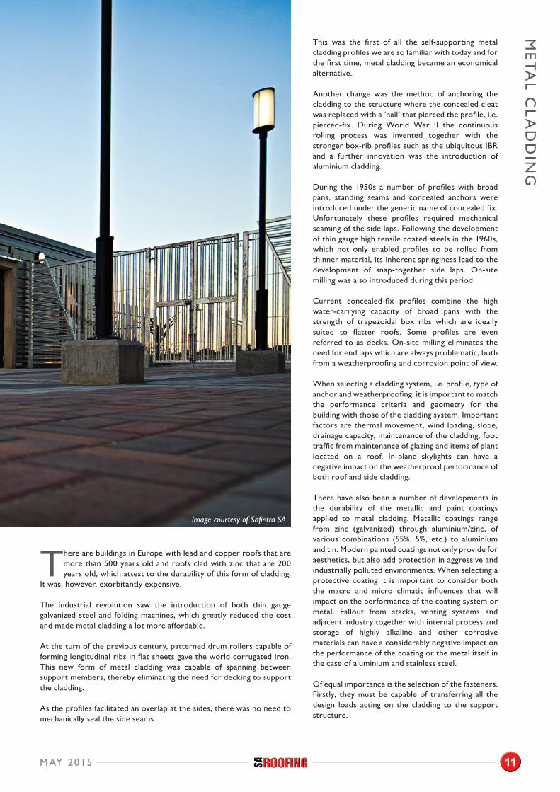
Image courtesy of Safintra SA
11

ME
TA
L C
LA
DD
ING
Secondly, it is vitally important that the durability of the protective coating to the fasteners and washers together with that of the compressible weatherproof seal between the washer and cladding is equal to or better than that to the cladding.
Thirdly, the weatherproof seal and coating to the fastener and washer must also be electrochemically compatible with the protective coating or the base metal. The weatherproof seal must be carbon free – EPDM seals are preferable.
Materials used to manufacture and fix flashings, rainwater goods and other ancillary items likewise also need to be electrochemically compatible with the protective coating or the base metal. Galvanized rainwater goods are adversely affected by rainwater drained from an aluminium/zinc, or other types of metal clad roofs. Flashings connecting metal cladding to solid items such as masonry, brickwork, etc. shall comprise of two unconnected parts in order to accommodate the differential in thermal movement of the materials. The use of paint-on membranes is not recommended. These products are not capable of accommodating the thermal movement and are particularly vulnerable to degradation when exposed to ultra-violet (UV) radiation.
Metal cladding can be combined with a variety of insulation materials to provide an economical, thermally efficient envelope to a building that complies with the requirements of SANS 204. However, in designing such systems, cognizance needs to be given to the elimination of thermal breaks where the metal cladding is connected to the support structure.
As with all engineered components, metal cladding systems are reliant on the alignment and structural stability of the supporting structure, coupled with the competence and integrity of the installer. Compliance with the manufacturer’s installation procedure and recommendations is paramount to the performance of any cladding system.
Metal cladding has evolved to meet the ever-changing requirements of architects and engineers to become a front runner when it comes to choosing a material for cladding. All the metals currently used for cladding are environmentally friendly and fully recyclable – a big plus in today’s world.
In South Africa the metal cladding industry is a major contributor to the construction industry. Unfortunately in recent years its image has become tainted as a result of the unscrupulous behavior of certain manufacturers and installers. Professionals and specifiers were becoming increasingly concerned about the performance of the industry and it was to this end that concerned individuals from across the industry decided to form the Southern African Metal Cladding and Roofing Association (SAMCRA) which was publically launched on 30 October 2013. Its objectives are to form a basis, including appropriate standards, on which an orderly industry can be built, to facilitate the fusion of the ambitions of the metal cladding industry with the requirements of the specifiers and clients to create a successful and respected industry, as well as promote the use of metal cladding.
To date SAMCRA has participated in the alignment of relevant national codes and the drafting of a code for the design, testing and installation of metal cladding. They have also successfully lobbied government departments to require all materials used in the production of metal cladding to carry an identifying mark, at regular intervals. The mark will include the name of the manufacturer, grade and thickness of material together with the type and thickness of coating plus date of manufacture. During 2015 SAMCRA will be presenting a series of workshops for professionals (architects, engineers and quantity surveyors) as well as building inspectors.
For more information, visit www.samcra.co.za.
MAY 2015
Image courtesy of De Beer and Associates: Architects
12
Cnr Berkley Road and Bax Street, Maitland, Cape Town 7405
T: 086 126 2866 F: 086 610 5441 W: www.corroshield.co.za E: [email protected]
TESTED BY:
MANUFACTURED BY ENGINEERING EDGE
AWARD WINNING FASTENERS
Tough enough for oil rigs Tough enough for your roofs
SINGAPORE

FIR
E T
EST
ING
A BRIEF HISTORY OF ROOFING MATERIALSRoofing materials are said to have been around since 10 000 BC in Neolithic China, and in Babylon, up to 5 000 years ago. From Babylon, clay roof tiles made their way to Greece and Rome. At that time, Rome was referred to as the ‘city of tiled roofs.’ The fire resistance of these roof tiles was recognized as early as 1212 AD by King John from England as he issued building by-laws to eliminate combustible roof materials.
The first composite roof material was found in New England in the 1840s. These roofs were made of felt or woven fabric that was covered with a tar-like substance. Later on, this type of composite roofing was made of coal tar, which was a by-product of the gas industry.
In terms of seasonal changes, some countries have always had more extremes in terms of temperature, and therefore had to find ways to maintain a comfortable living environment. Roof insulation materials were already used by prehistoric people to protect themselves from the elements. At first, organic materials were used and later, more durable substitutes. It is interesting to note that modern alternatives that are environmentally friendly, are techniques used in ancient times as insulation.
Later on, and up to the mid 1970s, asbestos was used as an insulation material because it was effective and could not burn. But its harmful effects were finally documented and the industry was forced to look for alternative methods of insulating roof systems.
OVERVIEW OF THE SABS FIRE ENGINEERING LABORATORY AND THE APPLICABLE STANDARDSThe SABS Fire Engineering Laboratory has been in existence for the past 60 years and performs fire safety tests on numerous materials and systems. The laboratory has the capability to test to most of the national standards that address the fire safety of buildings.
SANS 10400 It all starts with the National Building Regulations and the SANS 10400 ‘Code of Practice for the Application of the National Building Regulations.’ Part L of this code of practice covers fire safety of roof assemblies and the following is an extraction from part L:
FIRE RESISTANCE AND COMBUSTIBILITY“The fire resistance of any roof or ceiling assembly (or both), complete with light fittings or any other component which penetrates the ceiling, and the degree of non-combustibility of such assembly shall comply with the relevant requirements in SANS 10400-T and SANS 10400-V, as applicable. No part of the roof or ceiling assembly, made of wood or any other combustible material, shall pass through a separating element of a building (in accordance with the requirements of SANS 10400-T).”
This clause refers to SANS 10400 Part T: ‘Fire Protection’ and SANS 10400 Part V ‘Space Heating.’ Herewith an extraction from Part T as it references the standards: “When any insulation, roof lining or waterproof membrane not used as a ceiling and used under a roof covering as part of a roof assembly, is tested in accordance with SANS 10177-5 – Fire testing of materials, components and elements used in buildings Part 1: General introduction to the methods of test, and found to be combustible, such material shall be acceptable should it be classified, marked and installed in accordance with the requirements of SANS 428 – Fire performance classification of thermal insulated building envelope systems.”
Part T also refers to SANS 10177 – Part 10 ‘Fire testing of materials, components and elements used in buildings – Surface burning characteristics of building materials using the inverted channel tunnel test’ as well as to SANS 10407:2006 ‘Thatched roof construction.’
A CLOSER LOOK AT THESE STANDARDS SANS 428 – ‘FIRE PERFORMANCE CLASSIFICATION OF THERMAL INSULATED BUILDING ENVELOPE SYSTEMS’This standard covers the classification, usage and application requirements for under-roof and side-cladding insulating materials, liners, insulated wall and roof panels, insulated ceilings and insulated wall- and ceiling coating systems for use in buildings of unlimited height when exposed to an ignition source. What follows are selected extractions from SANS 428 to identify the additional standards that are referenced in terms of the fire safety of roof systems:
“Combustible insulation materials used in occupancies E4, H3, H4 and H5 as under tile or under roof linings shall be tested only in accordance with SANS 10177-10 and classified accordingly. Insulation installed on top of ceilings shall be tested in accordance with BS 5803-4 and SANS 10177-10.
Fire Testing of Roofing and Insulation Materials at SABS Fire Engineering Laboratory
Article by Erich Seeger, Pr. Sci. Nat – Senior Manager: Civil & Mechanical Testing Laboratories
14 MAY 2015

Ceiling systems shall not be used as fire barriers unless designed as such and tested for compliance with SANS 10177-2 for the respective intended use. Interior insulated ceiling systems shall be tested with the maximum thickness of insulation and be representative of the intended usage and installed as would be the case in practice.”
SANS 10177 – PART 2 – ‘FIRE TESTING OF MATERIALS, COMPONENTS, AND ELEMENTS USED IN BUILDINGS’
This part of SANS 10177 covers the method of test used to determine the fire resistance of any element given in the following list, on the basis of the length of time within which a representative test specimen of specified dimensions will satisfy the criteria in respect of stability, integrity, and insulation:
a) Wall (load-bearing and non-load-bearing)b) Partitionc) Columnd) Beame) Floorf) Ceiling systemg) Door and shutter assembly
SANS 10177 – PART 5 – ‘FIRE TESTING OF MATERIALS, COMPONENTS, AND ELEMENTS USED IN BUILDINGS NON-COMBUSTIBILITY AT 750°C OF BUILDING MATERIALS’
This part of SANS 10177 covers the method of test used to determine the non-combustibility at 750°C of homogeneous and non-homogeneous building materials except electrical components and cables that are used in buildings. This method
of testing is not applicable to surface finishing materials less than 1mm thick.
The testing procedure is to basically heat the furnace (Photo 1) and allow the furnace temperature to stabilize at (750 ± 7.5)°C, place the specimen in the
specimen holder and insert it into the furnace for 20 minutes. Record the temperature readings from the specimen and furnace thermocouples at intervals of 30s or less, and observe the duration of any flaming.
The material shall be deemed non-combustible if, during the test, none of the three specimens either:
• Caused the temperature reading from either of the two thermocouples to rise by 50°C or more above the initial furnace temperature; or
• Is observed to flame continuously for 10s or more inside the furnace.
Otherwise, the material shall be deemed combustible.
SANS 10400 PART VThe functional regulation contained in part V of the National Building Regulations is about the design and construction of any flue pipe, chimney, hearth or fireplace. Flue pipes shall be designed and installed in such a manner that it will not cause a fire hazard to adjacent material.
SANS 10177 – PART 10 – ‘FIRE TESTING OF MATERIALS, COMPONENTS AND ELEMENTS USED IN BUILDINGS’Surface burning characteristics of building materials using the inverted channel tunnel test.
In the Republic of South Africa the national standard; i.e., SANS 10400 – Part T ‘Fire Protection’ forms part of the National Building Regulations. It is of absolute essence that each and every person involved in the fire protection chain has a copy of this standard, and, more importantly, understands the application of this document. This regulation refers one to SANS 10177 – Part 10, ‘Fire testing of materials, components and elements used in buildings – Surface burning characteristics of building materials using the inverted channel tunnel test.’
• Scope This standard covers the method of test to determine the surface burning characteristics of materials when exposed to fire, and this method is suitable for the classification of all combustible or non-combustible materials for surface applications such as under-roof and side-cladding.
• Principle This test method determines comparative burning behaviour of interior building surfaces and predicts the potential for a self-propagating fire spread by measuring the maximum flame spread. This method covers three adjacent surfaces; i.e., two walls and a ceiling and the inverted tunnel is so designed to produce a combination of conductive, convective and radiative heat flux properties of any material.
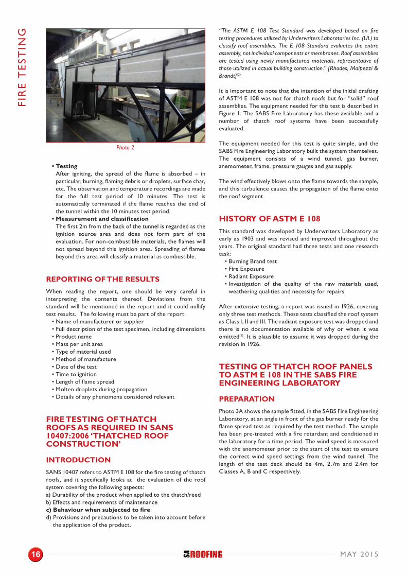
• Apparatus The inverted tunnel (Photo 2) is 7.4m long and 2.4m high, and the cladding and ceiling plus insulation materials will be installed into this channel. The test specimens are either supported on test frame or they are installed as in practice. The fire source is situated in the centre of the fire-end of the structure, and when the fuel is ignited, it produces a fire exposure of about 18kW. Thermocouples measure the surface temperatures at many different locations.
FIRE
TE
STIN
G
A typical set-up for Part 2
Photo 1
MAY 2015 15
• Testing After igniting, the spread of the flame is absorbed – in particular, burning, flaming debris or droplets, surface char, etc. The observation and temperature recordings are made for the full test period of 10 minutes. The test is automatically terminated if the flame reaches the end of the tunnel within the 10 minutes test period.
• Measurement and classification The first 2m from the back of the tunnel is regarded as the ignition source area and does not form part of the evaluation. For non-combustible materials, the flames will not spread beyond this ignition area. Spreading of flames beyond this area will classify a material as combustible.
REPORTING OF THE RESULTSWhen reading the report, one should be very careful in interpreting the contents thereof. Deviations from the standard will be mentioned in the report and it could nullify test results. The following must be part of the report:
• Name of manufacturer or supplier• Full description of the test specimen, including dimensions• Product name• Mass per unit area• Type of material used• Method of manufacture• Date of the test• Time to ignition• Length of flame spread• Molten droplets during propagation• Details of any phenomena considered relevant
FIRE TESTING OF THATCH ROOFS AS REQUIRED IN SANS 10407:2006 ‘THATCHED ROOF CONSTRUCTION’
INTRODUCTIONSANS 10407 refers to ASTM E 108 for the fire testing of thatch roofs, and it specifically looks at the evaluation of the roof system covering the following aspects:a) Durability of the product when applied to the thatch/reedb) Effects and requirements of maintenancec) Behaviour when subjected to fired) Provisions and precautions to be taken into account before the application of the product.
“The ASTM E 108 Test Standard was developed based on fire testing procedures utilized by Underwriters Laboratories Inc. (UL) to classify roof assemblies. The E 108 Standard evaluates the entire assembly, not individual components or membranes. Roof assemblies are tested using newly manufactured materials, representative of those utilized in actual building construction.” [Rhodes, Malpezzi & Brandt](2)
It is important to note that the intention of the initial drafting of ASTM E 108 was not for thatch roofs but for “solid” roof assemblies. The equipment needed for this test is described in Figure 1. The SABS Fire Laboratory has these available and a number of thatch roof systems have been successfully evaluated.
The equipment needed for this test is quite simple, and the SABS Fire Engineering Laboratory built the system themselves. The equipment consists of a wind tunnel, gas burner, anemometer, frame, pressure gauges and gas supply.
The wind effectively blows onto the flame towards the sample, and this turbulence causes the propagation of the flame onto the roof segment.
HISTORY OF ASTM E 108This standard was developed by Underwriters Laboratory as early as 1903 and was revised and improved throughout the years. The original standard had three tests and one research task:
• Burning Brand test• Fire Exposure• Radiant Exposure• Investigation of the quality of the raw materials used,
weathering qualities and necessity for repairs
After extensive testing, a report was issued in 1926, covering only three test methods. These tests classified the roof system as Class I, II and III. The radiant exposure test was dropped and there is no documentation available of why or when it was omitted(1). It is plausible to assume it was dropped during the revision in 1926.
TESTING OF THATCH ROOF PANELS TO ASTM E 108 IN THE SABS FIRE ENGINEERING LABORATORY
PREPARATIONPhoto 3A shows the sample fitted, in the SABS Fire Engineering Laboratory, at an angle in front of the gas burner ready for the flame spread test as required by the test method. The sample has been pre-treated with a fire retardant and conditioned in the laboratory for a time period. The wind speed is measured with the anemometer prior to the start of the test to ensure the correct wind speed settings from the wind tunnel. The length of the test deck should be 4m, 2.7m and 2.4m for Classes A, B and C respectively.
FIR
E T
EST
ING
Photo 2
16 MAY 2015

FIRE
TE
STIN
G
Figure 1
Photo 3A Photo 4
MAY 2015 17

ONSET OF THE TESTThe gas burner is ignited and the wind tunnel is switched on, and within seconds the required flame is propagated as shown in Photo 3B. The gas pressure is also tightly controlled. Note the clock at zero minutes at the right-hand bottom.
For Class A and B tests the flame is applied for 10 minutes and for the Class C test the flame is applied for 4 minutes.
DURING TESTINGPhoto 6 was taken 5 minutes after ignition of the flame. Note the effect of the wind turbulence on the flame. The flame temperature is maintained at 760˚C for Classes A and B and at 704˚C for Class C. The temperature is measured with a type K thermocouple.
During the testing period, the test sample is observed for the distance to which the flame has spread, the occurrence of flaming or glowing brands, and displacement of portions of the sample.
Photo 4 was taken at 10 minutes just prior to the wind and flame being shut down. Note the spread of the flame by looking at the charred surface of the deck. During the flame spread test the flaming shall not spread beyond 1.8m for Class A, 2.4m for Class B and 4m for Class C. The lateral spread of the flame should be insignificant.
Photo 5 was taken after the flame had been shut down.
The spread of flame test measures the potential flame spread characteristics of the surface of the roof assembly or system.
CONCLUSIONThe standard ASTM E 108 does provide a way to determine the fire performance of a roof system. The many variables; i.e., wind speed, sample preparation, and surface temperature may vary, resulting in variation of the results.
REFERENCES:1. ASTM E 108 ‘Standard Test Methods for Fire Tests of Roof
Coverings’2. Exterior Fire Performance of Low-Slope Roof Assemblies
- Rhodes, Malpezzi & Brandt3. SANS 10400 Part T ‘Fire Protection’4. SANS 10400 Part A ‘General Principles and Requirements’5. Summerland Fire Commission (SFC) findings report6. SANS 10177 Part 2 ‘Fire testing of materials, components, and
elements used in buildings’ 7. SANS 428 ‘Fire performance classification of thermal insulated
building envelope systems’8. SANS 10407:2006 ‘Thatched roof construction’SANS 10177 – Part 5 ‘Fire testing of materials, components,
and element used in buildings Non-combustibility at 750 °C of building materials’
FIR
E T
EST
ING
Photo 3B
Photo 5
Photo 6
18 MAY 2015

THE THATCHERS ASSOCIATION OF SOUTH AFRICA STRIVES TO UPHOLD HIGH STANDARDS OF PRACTICE FOR THE THATCHING INDUSTRY, MEMBERS AND THEIR CUSTOMERS. TASA AIMS TO DO THE FOLLOWING:
THE MARK OF EXCELLENCE!
FOR MORE INFORMATION, CONTACT ELZABIE MEINTJES: (c) 083 283 8429(e) [email protected](w) www.sa-thatchers.co.za
FOR MEMBERS:• Establish and exercise a code of ethics.• Establish and maintain minimum standards and requirements.• Promote interaction through marketing and socialising.• Establish and maintain a membership list.• Pro-active promotion programmes to enhance the image of the Association.
FOR CONSUMERS:• High visibility for Association and its members.• Highlighting poor workmanship and malpractice.• Marketing of the Association and the trade in general in SA and overseas.• Awareness of the SANS 10407 Specification and requirements.• Liaison with the NHBRC.•• Awareness of skills and products of members.


LEG
ISL
AT
ION
DUTIES OF THE PRINCIPAL CONTRACTOR AND SUB-CONTRACTOR (CR 7)When the Construction Regulations of 2014 came into effect, regulations around the contractor’s duties generally remained the same, with changes in the structure made in an attempt to improve the understanding of the relationship between the principal contractor and the appointed contractors, as well as contractors appointed by those contractors. It would appear that there is duplication, but this is to address the appointment of second, third, and even more level appointments.
A PRINCIPAL CONTRACTOR MUST:• Supply to the client a suitable, sufficiently documented and
coherent site-specific health and safety plan, based on the client's documented health and safety specifications. The plan must be applied from the start of the project and for the duration of the construction work and must be reviewed and updated by the principal contractor as work progresses.
• Open, and keep on site, a health and safety file that must include all relevant documentation. The file must be available on request to an inspector, the client, the client’s agent, or a contractor.
The ‘New’ Construction Regulations: Part 3
In the previous issue of SA Roofing, we reviewed the Construction Regulations of 2014 and how certain updates within the current legislation impact industry today. In this, our concluding series instalment, we focus
more closely on the duties of the principal contractor and sub-contractor as they could pertain to the roofing sector.
Image by Sheila Sund
Article by: Douglas (Doug) Michell, MBA North – Construction Health and Safety
22 MAY 2015

BEFORE APPOINTING ANY OTHER CONTRACTOR:
• Provide the relevant sections of the health and safety specifications to contractors who are tendering on work for the principal contractor.
• Ensure that potential contractors made sufficient provision for health and safety measures.
ENSURE THAT EVERY APPOINTED CONTRACTOR:
• Has the necessary competencies and resources to perform the construction work safely.
• Is registered and in good standing with COIDA/FEM.
WRITTEN REQUIREMENTS UPON APPOINTMENT OF CONTRACTORS:
• Health and Safety Plan• Discuss and negotiate the contents of the health and
safety plan and approve that plan for implementation.• Ensure that a copy of all relevant health and safety plans
is available on request to an employee, an inspector, a contractor, the client or the client's agent.
• Take reasonable steps to ensure that each contractor's health and safety plan is implemented and maintained on the construction site.
• Stop any contractor from executing construction work not in accordance with the client’s health and safety specifications and the principal contractor's health and safety plan for the site, or work that poses a threat to the health and safety of persons.
• Operational controls apply to ALL contractors:• Ensure that periodic site audits and document
verification are conducted at intervals mutually agreed upon – but at least once every 30 days.
• Where changes are brought about to the design and construction, make available sufficient health and safety information and appropriate resources to the contractor to execute the work safely.
• Take reasonable steps to ensure co-operation between all contractors appointed by the principal contractor to enable compliance with the regulations.
• Do not allow any employee or person to enter any site unless they have undergone health and safety induction training pertaining to the hazards on the site at the time of entry. (Update induction training to reflect conditions on site.)
• In addition to making sure that all visitors undergo health and safety induction, ensure that the visitors have the necessary personal protective equipment.
• Keep coherent site records of the health and safety induction. These records must be accessible for examination by relevant stakeholders.
• Relevant construction health and safety (CHS) training records must be made available on request to an inspector, the client, the client’s agent or the principal contractor.
• Ensure that all the contractor’s employees have a valid medical certificate of fitness specific to the construction work to be performed. The certificate must be issued by an occupational health practitioner in the form of Annexure 3.
• Consolidated health and safety fileThis element causes confusion in that the intention is to provide the client with information relevant to maintaining the structure going forward (information that may have an impact on persons who may have to perform the maintenance, alterations, etc.). The consolidated health and safety file must be handed over to the client on completion of the construction work.• Include a record of all drawings, designs, materials used
and other similar information concerning the completed structure;
• Include and make available a comprehensive and updated list of all the contractors on site accountable to the principal contractor, as well as the agreements between the parties and the type of work being done.
Sub-regulation (2) mirrors the duties of the principal contractor, but includes a specific sub-section (2)(d), which states: “...Co-operate with the principal contractor as far as is necessary to enable each of them to comply with the provisions of the Act...”
CONSTRUCTION MANAGEMENT AND SUPERVISOR APPOINTMENTS (CR 8) The regulations look to address the current structures on a construction project. The previous 2003 regulations identified the ‘construction supervisor’ as the person most likely to carry decisive responsibility on a construction site. This led to debate on how management should be appointed and by whom. The 2014 regulations identify an organizational structure where the ‘construction manager’ takes responsibility for the management of the project (including health and safety) and may appoint assistant managers to manage, and construction supervisors to supervise, the construction at the work face.
The principal contractor is required to appoint, in writing, one full-time competent person as the construction manager with the duty of managing all the construction work on a single site, including compliance with the occupational health and safety regulations. Where this person cannot be on site, an alternate must be appointed. This person may not be appointed to manage other construction sites.
Where the size and risk profile of the project demands it, one or more assistant construction managers may be appointed for different sections of the project. If an inspector deems it necessary, he or she may direct the construction manager in writing to appoint additional assistant construction managers.
Through a process of consultation with the client, taking into account the size of the project and the risk profile, it may be necessary to appoint a full-time or part-time construction health and safety officer in writing to assist in the control of all health and safety related aspects on the site. Where there is debate on whether a construction health and safety officer is necessary, the decision of an inspector is decisive. The appointed construction health and safety officer must have the necessary competencies and resources to assist the contractor and must be registered with a statutory body approved by the Chief Inspector (e.g. the SACPCMP or The South African Council for Project and Construction Management Professions).
LEGISL
AT
ION
MAY 2015 23

LEG
ISL
AT
ION CONSTRUCTION SUPERVISION AND
THE SUB-CONTRACTOR As stated, the construction manager must appoint construction supervisors in writing to supervise construction activities and ensure occupational health and safety compliance. The appointed supervisor may not supervise any construction work on or in any construction site other than the site appointed to, unless a sufficient number of competent employees have been appropriately designated on all the relevant construction sites.
Considering the size and risk profile of the project, the contractor must appoint one or more competent employees for different sections to assist the construction supervisor, having the same duties as the construction supervisor and clearly defined in the letter of appointment. An inspector may instruct the contractor to appoint the number of employees indicated by the inspector.
CONTROL AND IMPACT The identified structures allow the construction manager to control site appointments and influence appointed contractors’ structures. The regulations define a competent person over and above the accepted definition as a person who is “familiar with the Act and with the applicable regulations.” This will require contractors to undergo some form of legal compliance training for construction managers.
REGISTRATION OF CONSTRUCTION HEALTH AND SAFETY (CHS) SPECIALISTSThe appointment of CHS specialists is dealt with in the regulations by suggesting that an ‘agent’ appointed to act on behalf of the client and an ‘officer’ appointed to assist the contractor should be registered with a statutory body approved by the Chief Inspector. This body will be declared in a ‘Notice of Approval’ attached to the regulations indicating the SACPCMP as that body.
The council was mandated by the CBE to develop criteria for registration of CHS specialists. The process identified that there should be three categories to address the current situation in construction. Three registration categories were identified and registration rules developed.
• Construction Health and Safety Agent (Pr CHSA)• Construction Health and Safety Manager (CHSM)• Construction Health and Safety Officer (CHSO)
RISK ASSESSMENT FOR CONSTRUCTION WORK (CR 9) The regulation stipulates that a contractor must perform risk assessments before any construction work begins, as well as during the construction work as the risk profile changes. Previously this regulation included the requirements for induction training and the process for medical fitness; these sections have since been moved to the contractor’s duties.
Where the previous regulations required a documented plan of safe work procedures, the 2014 regulation requires a documented method for the analysis of, and the risks and
hazards identified, which should include a plan for review. The advantage for the contractor is that the procedure is submitted to the client and/or principal contractor along with the CHS plan, which must be agreed to and approved. This may prevent later exchanges between client and contractor of formats not being acceptable.
Audits also identify multiple formats for one site, causing the process to be ineffectual due to lack of understanding by workers. The draft regulations of 2010 suggested that the risk assessments should be reviewed at intervals not exceeding one month, whereas the 2014 regulation requires a review plan through which the risk assessments are reviewed when the risk profile changes, taking into account design, construction methods, etc.
FALL PROTECTION (CR 10)A significant update within current legislation is the reference to a ‘fall risk,’ which is defined as: “Any potential exposure to falling either from, off or into...” The requirement that a contractor must designate a competent person to be responsible for the preparation of a fall protection plan remains in place; the contractor must still ensure that the fall protection plan is implemented, amended where and when necessary, and maintained as required. Steps must be taken to ensure continued compliance with the fall protection plan. Under the acceptable appointment structures, this means that the appointed ‘contracts manager’ must have the most up-to-date version available.
An important regulation pertinent to fall protection plans is the need for a rescue plan that details the necessary procedure, personnel and suitable equipment required to effect the rescue of a person in the event of a fall incident. The need to place warning signs in prominent places is no longer a stipulation, but the contractor may still choose to have this as part of the overall fall protection plan.
‘Fall risk’ could be left open to interpretation and create unrealistic demands from ‘agents.’ However, there is more scope for the contractor who provides a detailed, coherent project or task-specific fall protection plan to address specific fall risks and reasonable controls. When drafting fall protection plans, consider the OHS Act Section 8 Duties of an Employer, in conjunction with CR 10 (4)(d) and the definitions of fall arrest and prevention equipment:
• Section 8(2)(b) – taking such steps as may be reasonably practicable to eliminate or mitigate any hazard or potential hazard to the safety or health of employees, before resorting to personal protective equipment.
• CR 10(4)(d) – fall arrest equipment is used only where it is not reasonably practicable to use fall prevention equipment.
• ‘Fall arrest equipment’ means equipment used to arrest a person in a fall, including personal equipment such as a body harness, lanyards, deceleration devices, lifelines or similar equipment.
• ‘Fall prevention equipment’ means equipment used to prevent persons from falling from a fall-risk position, including personal equipment, a body harness, lanyards, lifelines or physical equipment such as guardrails, screens, barricades, anchorages or similar equipment.
24 MAY 2015

STRUCTURES (CR 11)A contractor must ensure that all reasonably practicable steps are taken to prevent the uncontrolled collapse of any new or existing structure due to the carrying out of construction work and that no structure or part of a structure is loaded in a manner which would render it unsafe.
Normal project controls have to be in place, meaning all drawings connected to the designs must be kept on site and be made available on request to an inspector, other contractors, the client and the client's agent or employee.
TEMPORARY WORKS (CR 12)This regulation replaces the former CR 10 ‘Form Work and Support Work’ and requires that a contractor appoints a temporary works designer in writing to design, inspect and approve the erected temporary works on site before use, and that all temporary works operations are carried out under the supervision of a competent person who has been appointed in writing for that purpose.
During the development of the regulation on temporary works, the technical committee invited experts in their field and the Institute for Work at Height. The regulation in essence came about as a result of their input and aims to address design, supply, erection and maintenance of the temporary works.
Sub-regulation 2 addresses operational controls, and is nothing more than good practice. A contractor must ensure that all temporary works structures are:
• adequately erected, supported, braced and maintained so that they are capable of supporting all anticipated vertical and lateral loads applied to them, and that no loads are imposed onto the structure that the structure is not designed to withstand;
• done with close reference to the structural design drawings, and where any uncertainty exists, the structural designer should be consulted; and that
• detailed activity-specific drawings are kept on site and be made available on request to an inspector, other contractors, the client, the client's agent or any employee; and furthermore, are
• erected, moved or dismantled by persons provided with adequate training and instruction to perform those operations safely.
BEFORE PLACING CONCRETE, TEMPORARY WORKS MUST BE:
• Inspected by a competent person immediately before, during and after the placement of concrete, after inclement weather or any other imposed load, and at least on a daily basis until the temporary works structure has been removed and the results have been recorded in a register and made available on site.
• No person may cast concrete, until authorization in writing has been given by the competent person contemplated as referenced above.
MAY 2015
10 Thora Cresent, Wynberg, Sandton, Johannesburg011 262 4151charles@frontier-electroinics.co.zabrinnosa.co.zafacebook.com/brinnoafrica

LEG
ISL
AT
ION • Upon casting concrete, the temporary works structure
must be left in place until the concrete has acquired sufficient strength to safely support its own weight and any imposed load, and is not to be removed until authorization in writing has been given by the competent person contemplated as referenced above.
EQUIPMENT:• All equipment used in temporary works structure must
be carefully examined and checked for suitability by a competent person before being used.
• If, after erection, any temporary works structure is found to be damaged or weakened to such a degree that its integrity is affected, it must be safely removed or reinforced immediately.
• Adequate precautionary measures must be taken in order to secure any deck panels against displacement, and prevent any person from slipping on temporary works due to the application of release agents.
• As far as is reasonably practicable, the health of any person must not be affected through the use of solvents or oils or any other similar substances.
• The foundation conditions must be suitable to withstand the loads caused by the temporary works structure and any imposed load in accordance with the temporary works design.
• Provision must be made for safe access by means of secured ladders or staircases for all work to be carried out above the foundation-bearing level.
DESIGN DRAWINGS:• A temporary works drawing or any other relevant
document must include construction sequences and methods statements.
• The temporary works designer must be issued with the latest revision of any relevant structural design drawing.
• A temporary works design and drawing must be used only for its intended purpose and for a specific portion of a construction site; and
• The temporary works drawings must be approved by the temporary works designer before the erection of any temporary works.
• No contractor may use a temporary works design and drawing for any work other than its intended purpose.
SUSPENDED PLATFORMS (CR 17 –PREVIOUSLY CR 11)Previously, sub-regulation 3 made reference to the certificate of system design issued by a Professional Engineer, certified engineer or professional technologist. The 2014 regulations refer to the ‘competent person’ as defined.
• The certificate of system design must be submitted for every new project.
• Requirements for the safe working load sign are specified.
• the maximum mass load;• the maximum number of persons; and• the maximum total mass load, including load and
persons, which the suspended platform can carry.
It is necessary to use a specialist supplier and write into the contract that all requirements of the Construction Regulation 17 must be complied with.
ROPE ACCESS WORK (CR 18 – REPLACED CR 16 BOATSWAIN’S CHAIR)Work-at-height specialists have expressed their concern over the removal of ‘Boatswain’s Chair’ from current legislation, as this equipment is still used extensively for work at height. But the Legislator chose to remove it from Construction Regulations and, instead, include it in the Mechanical Regulations as it is deemed to be equipment that is not used exclusively in the construction environment.
The regulation requires the contractor to appoint a competent person in writing as a rope access supervisor with the duty of supervising all rope access work on the site, including the duty of ensuring occupational health and safety compliance in relation to rope access work.
Note that all rope access operators must be competent and licensed to carry out the work. Sub-regulation 2 states the operational requirements: No contractor may use or allow the use of rope access work unless –
• in possession of a site – and job-specific fall protection plan developed by a competent person before work starts, which includes records of maintenance and inspections of all the equipment used for the work operations; unless
• the design, selection and use of the equipment and anchors comply with the safety standards incorporated into the regulations; and unless
• measures are in place to allow rescue procedures to commence immediately in the event of a fall incident.
This is considered specialist work that contractors should not attempt to perform unless they have the required skills and competencies. Specialist contractors, associated with the Institute for Work at Height, should be appointed.
CONSTRUCTION EMPLOYEES’ FACILITIES (CR 30 – PREVIOUSLY 28)Current legislation did see a title change from ‘welfare’ to ‘employees,’ but the regulation has otherwise remained basically the same, requiring compliance with the Facilities Regulations, 2004, promulgated by Government Notice No. R. 924 of 3 August 2004. CR 30(1)(a) includes the opportunity for there to be consultation with the employees or employees’ representatives on the provision of shower facilities, or at the minimum at least one shower facility must be available for every 15 persons.
CONSTRUCTION HEALTH AND SAFETY TECHNICAL COMMITTEE (CR 31)This new regulation makes provision for the establishment of a construction health and safety technical committee that will be made up of representatives from government agencies, higher education, employers’ organisations operating in construction, labour, and consultants. Persons deemed to be experts in this field may be co-opted onto the committee.
26 MAY 2015
Appointments are made for a determined time period but a member may be discharged for fair and just reasons. The functions and duties of this committee include:
• Advising the chief inspector on construction-related codes, standards and training requirements;
• Designating persons in writing to examine safety systems and safety records of companies that have high incident rates, and providing recommendations to the chief inspector of occupational health and safety on the findings;
• Making recommendations and submitting reports to the chief inspector of occupational health and safety regarding any matter to which these regulations relate;
• Advising the chief inspector of occupational health and safety regarding any matter referred to the Construction Regulations Technical Committee by the chief inspector of occupational health and safety;
• Performing any other function for the administration of a provision of these regulations that may be requested by the chief inspector of occupational health and safety;
• Conducting its work in accordance with the instructions and rules of conduct framed by the chief inspector of occupational health and safety; and
• Referring appeals against decisions of the Construction Regulations Technical Committee to the chief inspector of occupational health and safety.
Procedures are stated for incidents where persons may be affected by a decision of the Construction Health and Safety Technical Committee for appeal against the decision.
APPROVED INSPECTION AUTHORITY (CR 32 – PREVIOUSLY 29)All previous appointments for OHS have been withdrawn. In addition to the appointment procedures, the legislator has added the requirement for the Approved Inspection Authority to perform its functions as prescribed by the guidance document issued by the Department of Labour for Approved Inspection Authorities.
OFFENCES AND PENALTIES (CR 33 – PREVIOUSLY 30)OHS Act penalties have been reviewed.
• Guilty of an offence and liable upon conviction to a fine or to imprisonment for a maximum of 12 months
• In the case of a continuous offence, not exceeding an additional fine of R200 or additional imprisonment of one day for each day on which the offence continues, provided that the period of such additional imprisonment will not exceed 90 days.
FOR MORE INFORMATION, CONTACT: Master Builders Association North (t) 0861 622 667 or 011 805 6611(e) [email protected](w) www.mbanorth.co.za
REFERENCE:OHS Act and Construction Regulations
LEGISL
AT
ION


ME
TA
L SH
EE
TIN
G
Steel is one of the ultimate building materials for sustainable buildings. It is light, very strong, long lasting, design- versatile and above all, it is 100% reusable and can be fully
recycled after its useful life.
A metal roof system made up of a series of everyday components can outperform any alternative systems for bespoke and specific thermal properties. Site-assembled systems are built up from their constituent parts on the building site. Critically, this system can be used for a new build as well as a retrofit over an existing metal roof.
The assembly consists of a steel liner sheet, a layer of insulation material, a bar & bracket spacer system and an outer profiled steel weather sheet, as illustrated.
Built-up cladding systems are supported by conventional secondary steelwork (purlins or side rails), at the published rates for spanning of the cladding sheets (typically in the order of 1.5m to 2.3m, depending on the applied loading) so no extra sub-structure is required.
LINER SHEETSLiner sheets are simply a profiled sheet of coated steel with a shallow trapezoidal profile and a sheet thickness of anything from 0.3mm-0.55mm.
The thickness of the liner sheet will depend on the required trafficability, spanning capability, the cladding installation method and the acoustic requirements of the cladding.
Where required, the acoustic performance of the cladding, in particular its ability to absorb internal sound and minimise reverberation, may be enhanced by the use of a perforated liner sheet.
Thinner gauge liner sheets are not strong enough to walk on, so it is essential that the insulation, spacer system and weather sheet are installed from access panels. Access panels are simply a few thicker profiled steel sheets with the same profile as the liner. These are loose laid and nested over the liner sheet and used as a platform. These panels can be equipped with adhesive non-slip strips. These sheets are shifted along the roof plane as work progresses.
Simple, clever sustainability in the built environment
Site-assembled built-up metal roof systems for optimal thermal performance
1. Weather sheet 2. Bar / Bracket3. Liner sheet 4. Insulation 5. Purlin
1
2
3
4
5
30 MAY 2015

Whether trafficable or not, the steel liner sheets still provide an excellent non-fragile barrier against falling once they have been fully fastened.
THE SPACER SYSTEMThe primary function of the spacer system is to support the weather sheet at the required height above the liner sheet. The components of the system must, therefore, possess sufficient strength to safely transmit the required loading through to the primary purlins, without deformation.
The bar & bracket system consists of steel bars (1), which provide continuous support to the weather sheet, supported
at intervals by steel brackets (2) firmly attached to the purlins through the liner. The bracket foot (3) must incorporate an EPDM pad (which acts as a thermal break) to minimise thermal bridging.
NOTE: In the absence of an engineered spacer system, the structural integrity of blanket insulation or rigid insulation boards installed over purlins are entirely reliant on the roofing fasteners and packers. The design lengths of the fasteners are often exceeded whilst the insulation and packers do not offer them adequate support. This places the entire roof assembly at risk.
ME
TA
L SHE
ET
ING
Liner sheet
The Spacer System
1.
2.
3.
MAY 2015 31

INSULATIONGlass fibre or mineral wool blankets are favoured due to their light weight, low thermal conductivity, acoustic performance, ease of handling, cost effectiveness and fire-performance.
Glass fibre and mineral wool blankets are flexible which ensures that gaps between the insulation are eliminated during installation, preventing thermal bridging.
THE OUTER ‘WEATHER’ SHEET:The outer profiled metal sheet of a double skin built up cladding system is known as the weather sheet. While protecting the building by forming a weather tight envelope, it also is a structural element, as it plays an important role in transferring externally applied loads, e.g. from wind, hail, snow and foot traffic, through to the secondary steelwork and the primary load bearing frame. The metal weather sheets are available in a wide variety of profiles, finishes and colours.
BENEFITS OF BUILT-UP SYSTEMSBuilt-up steel systems offer savings of approximately 10% to rigid insulation board applications of equal R-values. They also offer savings by fast tracking the critical path of the project.
1. Cost effective2. Lightweight and easy to install: Fast method of
construction3. Secure and waterproof at an early stage of the build
programme, which means that internal works can continue within a waterproofed environment.
4. Efficient: R-values up to 7m2 K/W can be achieved, and the system offers consistent thermal performance for the life of the building.
5. Improved structural performance: The liner sheet and engineered bar & bracket spacer system provides restraint to the steel purlins, thus ensuring rigidity of the roof structure.
6. Fire performance: Glass fibre and mineral wool deliver an A/A1/1 fire-rating with no restrictions.
7. Acoustic performance: The acoustic performance of steel built-up systems far exceeds that of rigid insulation boards installed over purlin and eliminates common problems such as rain drumming.
8. Improved security due to a second steel skin within the roof assembly.
9. Recyclable and reusable: As the individual components are not bonded, recycling of the materials after the building’s operational life does not present the potential ecological impact presented by foam cored composite panels.
Safintra manufactures metal sheeting in a variety of profiles to suit most applications and designs. Technical advice is gladly offered at design and installation stages of the project.
For more information, visit www.safintra.co.za.
ME
TA
L SH
EE
TIN
G
Weather sheet
Insulation blanket
32 MAY 2015
0
5
25
75
95
100
Safintra corporate ad for SA Roofing
Monday, March 30, 2015 2:26:30 PM
ASP
HA
LT R
OO
F SH
ING
LES
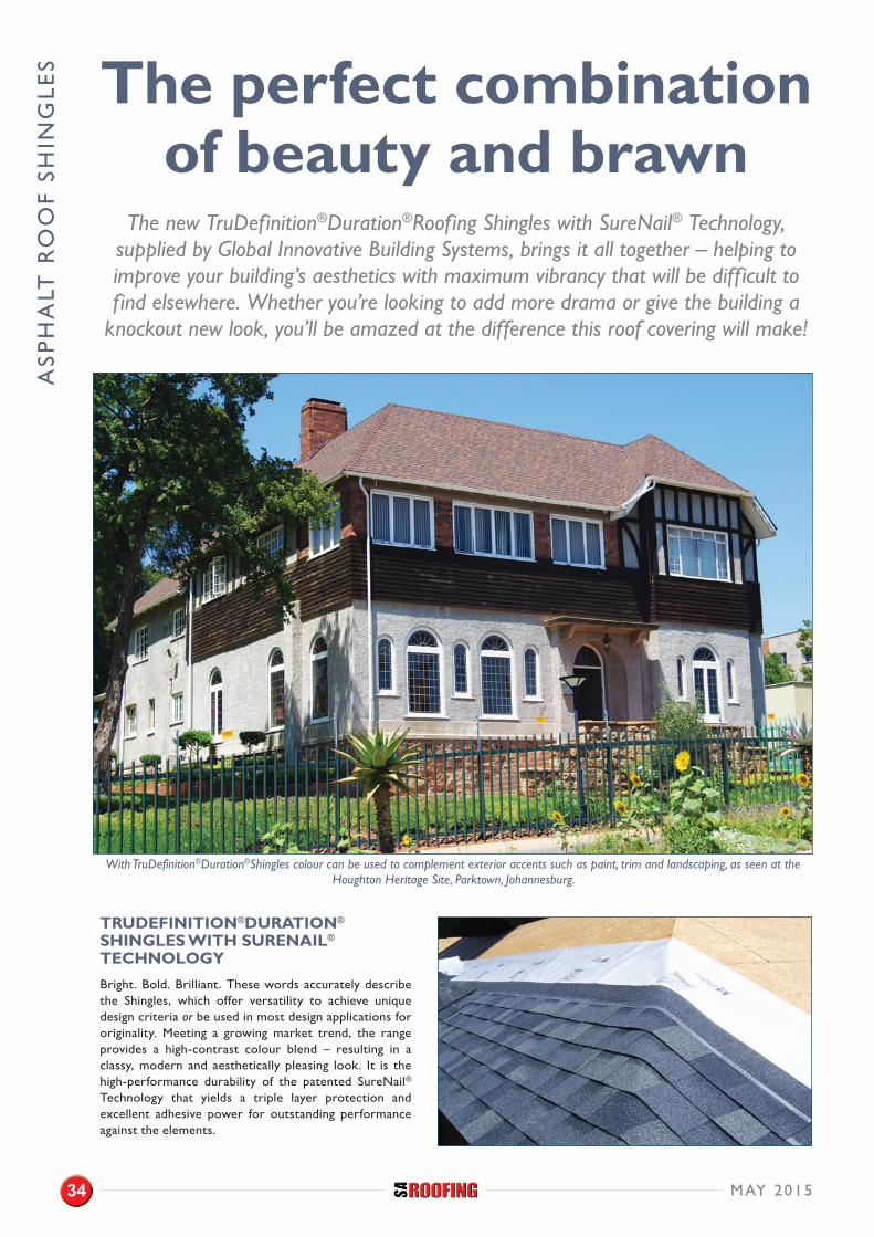
TRUDEFINITION®DURATION® SHINGLES WITH SURENAIL® TECHNOLOGYBright. Bold. Brilliant. These words accurately describe the Shingles, which offer versatility to achieve unique design criteria or be used in most design applications for originality. Meeting a growing market trend, the range provides a high-contrast colour blend – resulting in a classy, modern and aesthetically pleasing look. It is the high-performance durability of the patented SureNail® Technology that yields a triple layer protection and excellent adhesive power for outstanding performance against the elements.
The perfect combination of beauty and brawn
The new TruDefinition®Duration®Roofing Shingles with SureNail® Technology, supplied by Global Innovative Building Systems, brings it all together – helping to improve your building’s aesthetics with maximum vibrancy that will be difficult to find elsewhere. Whether you’re looking to add more drama or give the building a
knockout new look, you’ll be amazed at the difference this roof covering will make!
With TruDefinition®Duration®Shingles colour can be used to complement exterior accents such as paint, trim and landscaping, as seen at the Houghton Heritage Site, Parktown, Johannesburg.
34 MAY 2015

TruDefinition®Duration® Shingles with SureNail® Technology
Ts&Cs apply. THE PINK PANTHERTM & © MGM. All Rights ReservedTel: (011) 903 7080/1/2/3/4
Can You Afford Not To?www.gissa.co.za

ASP
HA
LT R
OO
F SH
ING
LES • Breakthrough design
The tough engineered reinforcing fabric of the SureNail® technology delivers consistent fastening, creating a durable unitary bonded roof covering.
• Triple Layer Protection™ A unique ‘triple layer’ reinforcement occurs when the fabric overlays the common bond area of the shingle laminate layers: A laminated shingle is constructed of two layers that partially overlap. Where they join in the centre at the fixing area, the SureNail® strip offers a third layer of protective reinforcement.
• Enhanced Sealant The enhanced TruBond® sealant grips tightly to the engineered fabric on the shingle below.
• Excellent Adhesive Power Specially formulated, wide adhesive bands help keep shingle layers laminated together.
Complete installation instructions are available on the Global Innovate Building Systems website at www.gissa.co.za.
A TECHNOLOGICAL BREAKTHROUGH IN ROOFING The TruDefinition®Duration® series incorporates the patented high performance SureNail® Technology and in conjunction with the enhanced wide band, TruBond® sealant provides outstanding resistance to high wind factors.
CALL 0861 727 663 TO BOOK YOUR
CLASSIFIED ADVERT
CALL 0861 727 663 TO BOOK YOUR SA ROOFING ADVERTS FOR 2015

Leaders in Roof Truss TechnologyFabricators
SheetersErectors
Tilers

TIM
BE
R T
RU
SSE
S
When the going gets tough
Challenges facing the truss fabricator and erector on siteBy Lyndsay Cotton, General Manager of LCP Roofing and Chairman of the ITC-SA

TIM
BE
R T
RU
SSES

TIM
BE
R T
RU
SSE
S
We have all heard the saying, ‘Go with the flow’. The question then is, ‘What is flow?’ According to a Special Health Report from Harvard Medical
School, the experience of ‘flow’ has certain characteristics:
1. Not being aware of time – the hours seem like minutes2. Not being aware of oneself – one's awareness is to the
activity itself, such as the hammer to the nail, the saw to the sprocket
3. External and interruptive thoughts are not inhibitive – complete focus and mastery of the task, the visualization of the project at its completion
4. One is active – you also have, to a large degree, total control of your activity
5. Work is effortless – everything fits and the components mesh into the whole
6. The will to repeat whole process or experience exists
The importance and relevance of this to the fabricator and erector on site is that flow on site is critical to the success factor and of equal importance to both the fabricator and erector alike, as each would like to successfully complete their given challenges on site and proceed to the next project.
CHALLENGES AND INTERRUPTIONS TO THIS ‘FLOW’ FACED BY THE ROOFER OFTEN INCLUDE THE FOLLOWING:
OUT-OF-SQUARE BUILDINGS
Unlike many European residential roof structures, fabricators in South Africa generally do not fabricate trusses to standard building dimensions and complex hip and valley structures are more the norm than the exception.
A roof structure cannot be made to ‘fit’ in the same manner that a floor tiler can ‘steal’ lines to fool the eye. Trusses cannot be adapted to accommodate tapering wall lines on plan for a variety of reasons, most notably being the dropping of the ridge lines with the resultant change in pitch.
Even if the trusses are all fabricated to the same size on an out-of-square structure, the support will gradually taper away from the heel line and each truss will require an additional heel support in an ever-incremental changing position. Apart from structural compromise and the obvious aesthetic reasons, the time and cost factor will be prohibitive.
WALL PLATES OUT OF LEVELAn out-of-level wall plate will often only manifest itself once the roof trusses have been erected and plumbed. The erector will attempt to level to roof structure by inserting wedges each side of the heel joint. It may even be required to insert an additional wall plate to solve the level dilemma. While this problem is less obvious on plastered structures, the beam fill on a face brick wall will immediately be evidence for the level differences. Obvious too, will be the dropping of sprocket or tile lines on each side of a hip set.
INCORRECT ROOF HOLDING DOWN ANCHORS OR PLACEMENTRoof anchor selection should be either two strands of 2.4mm galvanised wire or a minimum of 30x1.2mm galvanised steel strap as per SANS 10400 part K.
Roof anchors should be installed according to a truss layout on plan which allows for a maximum of 200mm offset from the heel. Should a truss layout not be sought prior to the final courses of brickwork it is unlikely that the anchors will then be placed in the correct position.
The only remedy to alleviate incorrectly placed anchors is to either fix and pin additional strapping to each truss, extending 600mm down the inner face of the wall or to install a shelf between all affected trusses with truss hangers and to fix the incorrectly placed anchor to the shelf.
40 MAY 2015

SLAB EDGESThe unfortunate result of incorrectly propped formwork and edge shutters is movement which causes concrete soffits and edges to ‘kick’.
Trusses are engineered by nature and are built in jigs in a factory environment under tolerances not often required in other trades. Trusses which are to be hung from slab and beam edges cannot easily be adapted on site to accommodate edges that are not cast according to the designed plan areas. In such instances, the designer has to be consulted in order that the required site remedials are to be proposed and no changes to this structural element should occur unless issued in writing on a site drawing.
BEAM FILLINGBricklayers will remove wedges inserted by the roof carpenter, thereby compromising the levels which then ultimately results in dipping and uneven roof surfaces. The roof structure is often also used to support dagha boards and scaffold planks while beam fill or gable-end masonry work is in process. The truss is not designed to accommodate these point loads and will fail, causing not only loss, but potentially injury as well.
SEQUENCING OF TRADESDue to program constraints, the main contractor will insist on the completion of the entire roof structure, including coverings in one operation.
No cognizance is then taken of plastering and painting of walls above lower roof surfaces, thereby creating untold and often irreparable damage to the roof coverings. Competent supervision and well-planned sequencing will ensure that all trades work in harmony without distress to the other.
ACCESS TO SITES BY DELIVERY VEHICLES
Roof trusses covering large spans are often unwieldy and slender and they are susceptible to damage due to twisting and snapping. Clear and unrestricted access for trusses and tiles, and a level, unobstructed lay-down area should be provided.
While the challenges facing the main contractor daily on site are legion, his attention to the abovementioned issues will go a long way in assisting the truss fabricator and roof erector to produce a quality completed product within the desired time frame.
The easiest way to escape from the problem is to prevent it and with prevention will follow success and with success, the will to repeat the experience.
For more information, visit www.lcproofing.co.za.
TIM
BE
R T
RU
SSES
MAY 2015 41

STE
EL
Clean COLORBOND™ steel at the Hotel Verde
Popular roofing material, Clean COLORBOND™ steel with Thermatech™ solar reflectance technology coating was used in the construction of ‘Africa’s
Greenest Hotel’, which is also one of the most sustainable designs in the world.
MAY 201542

The Hotel Verde, near Cape Town International Airport, achieved Platinum certification across all categories of LEED Platinum Design and Construction Certification in
May 2014. Hotel Verde is the first hotel in Africa to have achieved a Platinum certification across all categories and among only about six hotels worldwide to have achieved it for the same category. It is also a first for a South African building to receive Platinum certification for design and construction.
According to engineer, André Harms of Ecolution Consulting, the lead sustainability consultant on the project since the design stage, the hotel boasts a high SRI roof which contributes in no small way to its very low heating and cooling energy usage. Harms is a trained electro-mechanical engineer who provided the expertise behind many of the high tech aspects of the building.
Having spent 15 months at the South African Research Centre in Antarctica, Harms knows what it is to value everyday resources and is applying this dedication to each facet of the project. “We had the opportunity to change the status quo there,” he says. “We looked at different ways of doing everything, right from the word go.” He collaborated closely with the project architects, Heinrich Gerstner Harding Architects.
The crowning glory of the Hotel Verde, its roof, consists of 1 510m2 of exposed sheet metal roofing plus a further 255m2 which is covered by PV panels. The roofing material is Clean COLORBOND™ Ultra steel with Thermatech™ solar reflectance technology coating to specification AZ200 (TCT 0.53 mm) and colour Enduring White.
STE
EL
MAY 2015 43

STE
EL
The SRI of this superbly efficient product is 85. This is one of the coolest operating roofing materials available and this is complemented by an outstanding dirt resistance property and long life which ensure the roof stays cooler for longer. The roof was installed in profile Brownbuilt Klip-Lok 406 by roofing contractor, Scheltema.
The Solar Reflectance Index (SRI) is widely used by green building rating tools to mitigate the Urban Heat Island (UHI) effect. SRI is a value that incorporates both solar reflectance and thermal emittance in a single value to represent a material’s temperature in the sun. SRI quantifies how hot a surface would get relative to standard black and standard white surfaces. In hot tropical climates, low thermal mass materials such as steel with light coloured roofs and walls can be used to reduce energy demand for internal cooling.
According to Wayne Miller, General Manager for BlueScope Steel in Southern Africa, the solar reflectance technology found in Clean COLORBOND™ steel lowers the surface temperature by absorbing less heat from the sun. “Thermatech™ optimises the thermal performance of every colour in the standard Clean COLORBOND™ steel and Clean COLORBOND™ Ultra steel palettes, without changing their appearance. This provides greater thermal comfort all year round whilst using less energy for air-conditioning and hence mitigating the UHI effect,” he says. “In addition, our product's outstanding dirt resistance property ensures the roof looks newer for longer. This also assists in cooling.”
In a comparison between a Clean COLORBOND™ and a conventional steel roof, both uninsulated, the positive effect of dirt resistance technology is illustrated. Tests show that after two years’ exposure, assuming an irradiance of 1 000W/m²,
exterior temperature of 36°C and a high thermal emittance value of 0.86, typical of pre-painted steels, the Clean COLORBOND™ steel roof’s temperature is almost 10° cooler than the conventional steel roof and it radiates more than 40W/m² less heat down into the building. This is a considerable easing of the HVAC load for any building, regardless of size.
Tests show that after two years’ exposure, assuming an irradiance of 1 000W/m², exterior temperature of 36°C and a high thermal emittance value of 0.85, typical of pre-painted steels, the Clean COLORBOND™ steel roof’s temperature is almost 10° cooler than the conventional pre-painted steel roof and it radiates more than 40W/m² less heat down into the building.
FOR MORE INFORMATION, CONTACT:
Wayne Miller(t) 021 442 5420(e) [email protected](w) www.bluescope.co.za
Photography by Gareth Griffiths Imaging
DIRT RESISTANCE ALSO ASSISTS IN COOLING
Roofing MaterialUninsulated
Clean COLORBONDTM Steel Roof
Uninsulated Conventional
Steel Roof
Roof sheet temperature °C
Unexposed 56.0 56.0
24 months' exposure 62.9 72.3
Radiant heat downwards W/sq.m
Unexposed 80.3 80.3
24 months' exposure 110.3 154.0
MAY 201544

BOOKNOW!
EXPLORENEW BUSINESS
OPPORTUNITIESAT AFRICA’S ONLY TIMBER MACHINERY, TOOLING, MATERIALS & FITTINGS EXHIBITION
9-11JUNE2016
Gallagher Convention Centre | Midrand | South [email protected] | +27 (0) 21 856 4334
www.woodexforafrica.com
Furniture & Kitchen production | Forestry & Sawmilling | Wood Materials, Machinery & Veneers Tools, Loggers & mobile Saws | Timber Construction and supply | Industry Surface & Treatment Technologies
Many more Timber related products, machinery and services.

TR
USS
ES
A network of more than 190 licensed roof truss manufacturers across South Africa provides a
competitive and economic solution to even the most complex of roofing problems. This MiTek fabricator network, using MiTek’s state-of-the-art software programs, provides high quality, purpose-engineered truss units to satisfy the needs of an increasingly complex roof market.
EXAMPLES ILLUSTRATING THE DIVERSITY OF APPLICATION:
RESIDENTIAL: Ideal for all types of residential roof structure applications from very small to extremely large. Also especially well suited to attic roof applications to create extra living space at a lower overall building cost – a benefit still under-utilized in South Africa.
Gang-Nail® prefabricated timber
roof structuresMiTek Industries South Africa (Pty) Ltd., a division of the worldwide MiTek
Group, is the leading roof truss system supplier in South Africa and the world.
46 MAY 2015

COMMERCIAL: Well suited for all types of commercial roof structure applications up to about 17m clear span, thereafter transportation can become challenging (site-splicing is however an option). Also especially well suited to steep pitched roof structures rather than very shallow structures.
MULTI-PURPOSE: Gang-Nail® prefabricated framed structures can be very successfully utilized in so many different ways from formwork and seating stands to simply exposed structures.
This clearly illustrates the simplicity, beauty and strength of Gang-Nail plated timber structures.
TR
USSE
S
MAY 2015 47

TR
USS
ES
EXTRAORDINARY: With special engineering input from MiTek’s own professional team of engineers it is possible to create some very large and unusual roof structures, as illustrated by the above two projects including a church roof structure of laminated timber and a sports hall with a 40m clear span.
FOR ADDITIONAL INFORMATION CONTACT:MiTek Industries South Africa (Pty) Ltd. (t) +27 11 237 8700(e) [email protected](w) www.mitek.co.za
48 MAY 2015

creating the advantage
World Leaders since 1956.
A network of more than 190 licensed roof truss manufacturers across South Africa, provides a competitive and economic solution to even the most complex of roofi ng problems. This MiTek fabricator network, using MiTek’s state-of-the-art software programs, provides high quality, purpose-engineered truss units to satisfy the need of an ever increasing complex roof market. The scope of MiTek’s services includes not only unrivalled expertise in terms of professional structural engineering service but also the extensive Research and Development into all aspects of timber and light gauge steel roof design and construction as well as a full range of manufacturing equipment - that makes MiTek a World Leader.
Prefabricated timber roof trusses
eCo Fasteners® are timber and steel fastening devices that provide strong and rigid connections to any building structure.
• Light Gauge Steel Trusses • Steel Wall Framing
LEADING ROOF TRUSS SYSTEM SUPPLIER IN SA AND THE WORLD
A network of more than 190 licensed roof truss manufacturers across
that provide strong and rigid
MiTek Park,754 16th Road, Randjespark, Ext. 34, Halfway House,1685. Midrand (Head Offi ce) Tel: + 27(0) 11 237 8700Cape Town Tel: 021 905 0244 • Durban Tel: 031 700 6332 • Port Elizabeth Tel: 041 581 7525email: [email protected] • www.mii.com/southafrica
*MiTek Industries South Africa (Pty)Ltd, a division of the worldwide MiTek Group.

EX
PAN
DE
D P
OLY
STY
RE
NE
Expansion is achieved by virtue of small amounts of pentane gas dissolved into the polystyrene base material during production. The gas expands under the action of
heat, applied as steam, to form perfectly closed cells of EPS, which occupy approximately 40 times the volume of the original polystyrene bead. The EPS beads are then moulded into appropriate forms suited to their application.
There are three main types of rigid foam insulation products currently being used in the building industry: Expanded Polystyrene (EPS), Extruded Polystyrene (XPS), and Polyisocyanurate (PIC). Each of these products has a different set of physical properties.
Insulating foam boards are split into two basic categories, namely thermoplastics and thermosets. Both EPS and XPS foams are thermoplastic foams, while Polyisocyanurate is thermoset foam.
EPS PRODUCT CLASSIFICATION (TYPES)EPS Products are divided into types as shown in Table 1 and 2. Type EPS T has specific impact sound insulation properties. Each type, except EPS S, which is not used in load bearing applications, shall satisfy two different conditions at the same time in order to ensure adequate product performance.
TABLE 1 – CLASSIFICATION OF EPS PRODUCTS (EN 13163):
Material properties of expanded polystyrene (EPS)
Expanded Polystyrene (EPS) is a lightweight, rigid, plastic foam insulation material produced from solid beads of polystyrene. The result
is an effective, lightweight insulation material for buildings.
TYPECOMPRESSIVE STRESS AT 10%
DEFORMATION (kPA)
BENDING STRENGTH
(kPA)
EPS S - 50
EPS 30 30 50
EPS 50 50 75
EPS 60 60 100
EPS 70 70 115
EPS 80 80 125
EPS 90 90 135
EPS 100 100 150
EPS 120 120 170
EPS 150 150 200
EPS 200 200 250
EPS 250 250 350
EPS 300 300 450
EPS 350 350 525
EPS 400 400 600
EPS 500 500 750
Image by Crispin Semmens
50 MAY 2015
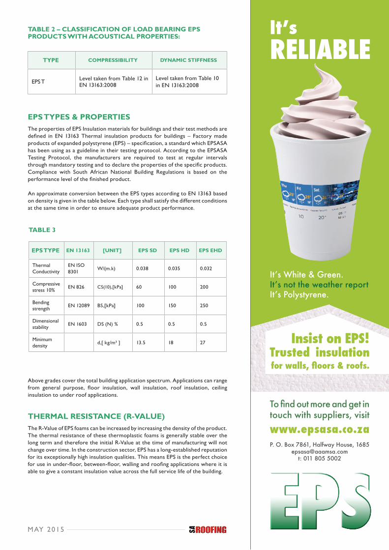
TABLE 2 – CLASSIFICATION OF LOAD BEARING EPS PRODUCTS WITH ACOUSTICAL PROPERTIES:
EPS TYPES & PROPERTIES The properties of EPS Insulation materials for buildings and their test methods are defined in EN 13163 Thermal insulation products for buildings – Factory made products of expanded polystyrene (EPS) – specification, a standard which EPSASA has been using as a guideline in their testing protocol. According to the EPSASA Testing Protocol, the manufacturers are required to test at regular intervals through mandatory testing and to declare the properties of the specific products. Compliance with South African National Building Regulations is based on the performance level of the finished product.
An approximate conversion between the EPS types according to EN 13163 based on density is given in the table below. Each type shall satisfy the different conditions at the same time in order to ensure adequate product performance.
Above grades cover the total building application spectrum. Applications can range from general purpose, floor insulation, wall insulation, roof insulation, ceiling insulation to under roof applications.
THERMAL RESISTANCE (R-VALUE) The R-Value of EPS foams can be increased by increasing the density of the product. The thermal resistance of these thermoplastic foams is generally stable over the long term and therefore the initial R-Value at the time of manufacturing will not change over time. In the construction sector, EPS has a long-established reputation for its exceptionally high insulation qualities. This means EPS is the perfect choice for use in under-floor, between-floor, walling and roofing applications where it is able to give a constant insulation value across the full service life of the building.
TABLE 3
MAY 2015
TYPE COMPRESSIBILITY DYNAMIC STIFFNESS
EPS T Level taken from Table 12 in EN 13163:2008
Level taken from Table 10 in EN 13163:2008
EPS TYPE EN 13163 [UNIT] EPS SD EPS HD EPS EHD
Thermal Conductivity
EN ISO 8301
W/(m.k) 0.038 0.035 0.032
Compressive stress 10% EN 826 CS(10),[kPa] 60 100 200
Bending strength EN 12089 BS,[kPa] 100 150 250
Dimensional stability EN 1603 DS (N) % 0.5 0.5 0.5
Minimum density d,[ kg/m³ ] 13.5 18 27
31655 - FA SA Roofing.indd 1 2014/12/11 1:19 PM

EX
PAN
DE
D P
OLY
STY
RE
NE FIRE SAFETY
All EPS products, as promoted by EPSASA, fulfil the requirements in accordance with the National Building Regulations SANS 10400-T Fire Protection.
WHERE TO USE EPS? Anyone who needs to thermally insulate walls, roofs or floors will find EPS the ideal, cost-effective and easy-to-use material in all types of buildings, from houses and offices to factories. EPS is used by civil engineers as a lightweight fill or void-forming material. It is also used as a flotation material.
For more information, visit www.epsasa.co.za.
TABLE 4: OVERVIEW OF EXAMPLES OF APPLICATIONS AND EPS PRODUCT TYPES
APPLICATION VERSUS EPS TYPE EPS SDEPS 60/100
EPS HDEPS 100/150
EPS EHDEPS 150/200
CELLARS
Internal insulation • - -
External, protected = • -
GROUND FLOORS
Slab-on-ground • • •
Concrete floor • • -
On construction floor • • -
FLOORS
Loft insulation • - -
Floating floors • • -
WALLS/GABLES
Cavity wall insulation • • -
SIPs/others • - -
Sandwich panels – steel • - -
External insulation • - -
ETICS • • -
PITCHED ROOFS
Internal insulation (all) • - -
Sandwich panels (all) • - -
External insulation • • 2) • 2)
FLAT ROOFS
Warm roofs •1) • •
Cool roofs • - -
Inverted roofs = = •
CIVIL ENGINEERING APPLICATION
All/general • • •
LEGEND
• normally used
= not possible from functional requirements
- not necessary/applied normally unless properties are explicitly needed
1) when load distribution boards are applied
2) when load bearing
52 MAY 2015

EXTRAORDINARY CHOICEA Fusion of technology in 7 layers for strength and protection The quality roofing solutions that saves you time and money
QUALITY AND INNOVATION
PRODUCTS TRADE ENQUIRIES
Our roofing systems protect thousands of homes, commercial and industrial buildings. Achieving a good looking product is not sufficient in competitive global markets. It is attention to detail in the manufacturing process that has earned our roofing systems an international reputation for excellence.
• DURA “V” Tile • Corrugated Profile (S-rib) - Galvanised and Colour Coated • Widespan Profile - Galvanised and Colour Coated • Bullnosing and Cranking - Galvanised and Colour Coated • Roofing accessories • Roll Formed Sections • • DURATRUSS - light weight stell trusses
IF IT DOES NOT SAY “D” IT’S NOT A DURAROOF TILE
tel: 031 940 4484 | email: [email protected]
Steelworld ensures its highest standards in quality and aesthetic appeal keeps in line with Steelworld hallmark in quality and innovation.
www.duraworld.co.za
PRODUCTS TRADE ENQUIRIESProducts Export• DURATILE• DUROMA• DURASPAN• DURA V TILE
• DURATILE• DUROMA• DURASPAN• DURA V TILE
• Roofing accessories
tel: 031 940 4484 | email: [email protected]
DURAROOF ensures its highest standards in quality and aesthetic appeal keeps in line with DURAROOF hallmark in quality and innovation.
www.duraroof.co.za

Tuesday 12 May 2015 11:00 – 18:00
Wednesday 13 May 2015 10:30 – 16:00
161 Maude Street, Sandown 2196 Johannesburg, South Africa
Registration and badge collection is on the ground floor – Maude Street entrance
Parking tickets are available at R35 and can be purchased at the show
Get your free ticket by visiting www.coatingsforafrica.org.za/register and use the *VIP CODE on the TOP LEFT to redeem this voucher and enjoy FREE entry
EXPO HOURS
PARKING
REDEEM THIS VOUCHER
ADDRESS
SEE, TOUCH AND EXPLORE the solutions of tomorrow from 120+ exhibitors who will be displaying:
R495 value compliments of: The South African Paint Manufacturers Association (SAPMA) and the Oil & Colour Chemists’ Association (OCCA) *VIP CODE: SARVT01
• Adhesives• Binders• Chemicalsandadmixtures• Equipmentandmachinery• Formulatorsofpaintandcoatings• Fillers• Ingredients
• Packaging• Pigments• Polymersandresins• Rawmaterials • Sealants• Solvents
FREE EXPO PASS
If you manufacture, sell, specify or work with paint and coatings in any capacity then this is your show!
WHy ATTEND?
• Develop your skills during FREE workshops and training on the exhibition floor
• Meet the entire paint and coatings value chain
• WIN! Lucky draw prizes to be won
[email protected] www.coatingsforafrica.org.za
11 - 13 MAY 2015Sandton Convention Centre, South Africa
Co-locatedwithOur hosts Presentingsponsor Platinum sponsor Silver sponsorGold sponsors

CONSTRUCTION WEEK: 11—15 MAY 2015
13 – 14 May 2015 | Sandton Convention Centre
This is your one-stop-shop to learn about
the latest construction innovations, technologies, drivers and investment
opportunities!
SEE, TOUCH AND EXPLORE the solutions of tomorrow from 220+
exhibitors who will be displaying:
• Building materials (glass, steel, timber, bricks, concrete)• Concrete and cement: Producers, readymix concrete contractors and manufacturers• Engineering, procurement and construction companies• Formwork and framework specialists• Construction tools, equipment and machinery• Paint, coatings and chemicals• Investors, project finance and finance houses• Low cost housing• Urban development• Bathrooms, kitchens and sanitary ware• Housing technologies and approaches
ADMIT 1 FREE EXPO VOUCHER
PRE-REGISTER AND YOU CAN WIN AMAZING PRIZES!
Wednesday, 13 May 2015: 11:30 – 18:00
Thursday, 14 May 2015: 10:30 – 16:00
161 Maude Street, Sandown 2196 Johannesburg, South Africa
Registration and badge collection is on the ground floor – Maude Street entrance
Parking tickets are available at R35 and can be purchased at the show
EXPO HOURS: PARKING: ADDRESS:
Sponsors and partners
Why attend?
Co-located with
• Develop your skills during FREE workshops and training on the exhibition floor
• Meetover 220 of the industry’s leading suppliers in just 2 days!
• WIN! Lucky draw prizes to be won
• Road construction technologies and solutions• Bitumen and asphalt• Physical infrastructure construction• Equipment maintenance• Public works• Contracting services• Fire suppression & protection• Finishes (gypsum and tiling)• Glass and glazing• HVAC• Insulation and sealants• Metal, steel, aluminium• Plumbing and water technology• Roads• Scaffolding• Software and IT• Construction transport logistics• Windows, doors and cladding
R495 VALUE compliments of: SA Roofing!
*VIP CODE: SARVIS01
Register today!Visit www.construction-week.com
Visit www.construction-week.comand use the *VIP CODE on the TOP to
redeem this voucher and enjoy free entry
REDEEM THIS VOUCHER ONLINE:
Client: Weza Afrika CapitalDate: 22 October 2013Project: Corporate Brand Assets

R360.00 INCLUSIVE FOR 10 ISSUES PLEASE NOTE THAT ADDITIONAL POSTAGE CHARGES ARE INCURRED FOR MAILINGS OUTSIDE OF THE RSA.
Please complete the form below and fax to: 0866 991 346
I would like to Subscribe to Renew my subscription to:
Nature of Business: .....................................................................................................
Company Name: ..........................................................................................................
PLEASE MAIL MY MAGAZINE TO:
Mr Mrs Ms Other
Surname: ..............................................First Name: ...................................................
Postal Address: ...........................................................................................................
E-mail: ............................................................ Website: ............................................
Tel: .................................................................. Fax: ...................................................
Date: ............................................................... VAT no:................................................
SUBSCRIBE TO
PAYMENT TO BE MADE TO:
Beneficiary: Trademax PublicationsBank: First National Bank - Century CityAccount no: 62187300092Branch code: 200909Reference: SUBS INITIALS SURNAME
ck 2008/097975/23
Proof of payment is attached
Please send invoice in order to make payment
www.trademax.co.zaPostnet Suite 241,Private Bag X103,N1 City, 7463
T: 0861 727 663F: 0866 991 346E: [email protected]

ROOFS THAT LAST
WHY DRY RIDGE?
QUALITY ROOFDry ridge & hip-line fixing with QuickRidge
Features• Ready to use: no unusual skills and minimal tools required for the roll and stick mechanism. • Time-saving: approximately 2.5hrs/10m roof versus mortar (approximately 6hrs/10m roof). • Light-weight: less demanding than mortar installations and less mess. • Cost-effective: no long-term maintenance associated with mortar bedding. • Secure and weather-proof: better resistance to wind and water penetration. • High quality, universal design that is aesthetically pleasing.
www.coverland.co.za | [email protected]
Mortar hardens therefore it does not expand and contract with
varying weather conditions or daily temperature variations.
Hairline cracks form which eventually increase in size.
Rain then penetrates the ridge and hip line through these cracks and cause damage to the interior of the roof.
Ongoing rain damage can cause trusses to rot which pose a serious health risk to the occupants of the
property.
Often maintenance to the ridge and hip-lines use the same
mortar method. An over coat of waterproofing is applied on top.
This looks unattractive and inevitably leads to future maintenance costs.
9367 MONIER AD QUICKRIDGE SAROOFING.indd 1 2015/02/19 08:23:25 AM

Logo Plexi
10 March 2014 02:39:19 PM
926 AdvertFinal.indd 1 2015/01/30 8:32 AM