sa ihs: test of digital systems - tu-ilmenau.de · sa ihs: test of digital systems r.ubar, ......
TRANSCRIPT

Integrierte Kommunikationssysteme
SA IHS: Test of Digital Systems
R.Ubar, A. Jutman, H-D. Wuttke, T. Vietzke

Integrated HW/SW Systems Group
© 2009 Integrated HW/SW Systems Group CATE 2009Copyright 2000-2003 by Raimund Ubar
2
Tallinn, Estonia

Technical University Tallinn, ESTONIACopyright 2000-2010 by Raimund Ubar / H.-D. Wuttke
3
Raimund Ubar
Tallinn Technical UniversityD&T Laboratory
Estonia
Design for Testability

Technical University Tallinn, ESTONIACopyright 2000-2010 by Raimund Ubar / H.-D. Wuttke
4
Vorlesung: Mittwochs 15:00-16:30Seminare: Blockveranstaltung
gegen Ende des Semesters
Prüfung: mündlich 20 Minuten
Rahmenbedingungen

Technical University Tallinn, ESTONIACopyright 2000-2010 by Raimund Ubar / H.-D. Wuttke
5
How to Teach Test Engineers?
The personwho is able
to program abroken
computer
Who is a test engineer ?

Technical University Tallinn, ESTONIACopyright 2000-2010 by Raimund Ubar / H.-D. Wuttke
6
Test Issues and Engineering Education
The importance of test (fault diagnosis) as a teaching objective is underestimated in traditional engineering education
Test is taught usually as a subtopic in a design courseIt is taught as an independent discipline only when it is a hobby horse of
the professor
Why?Because Test is interpreted as a nonproductive issue (vs. design)Tenhunen’s Law: The number of courses that should be taught at
universities doubles in a decade(Tenhunen, EWME, Lausanne, April 2004)

Technical University Tallinn, ESTONIACopyright 2000-2010 by Raimund Ubar / H.-D. Wuttke
7
Emerging Trend to Self-Testing Systems
Source: ElcoteqSource: Intel

Technical University Tallinn, ESTONIACopyright 2000-2010 by Raimund Ubar / H.-D. Wuttke
8
Objective of the Course
SpecificationHardware description
languages (VHDL)
ImplementationFull custom, standard
cell, gate arrays
ManufacturingCMOS
IHS2: VLSI Design Flow
TestingAutomatic test
equipment (ATE), structural scan testing
Built-in Self-Test
VerificationSimulation. Timing analysis,
formal verification
Test

Technical University Tallinn, ESTONIACopyright 2000-2010 by Raimund Ubar / H.-D. Wuttke
9
Problem
• The increasing complexity of VLSI circuits has madetest generation one of the most complicated and time-consuming problems in digital design
• The more complex systems are getting, the moreimportant will be the problems of test and design fortestability
• The most important question is today:How to improve the test quality at continuouslyincreasing complexities of systems?

Technical University Tallinn, ESTONIACopyright 2000-2010 by Raimund Ubar / H.-D. Wuttke
10
Goals of the Course
• The main goal of the course is to give the basic knowledge to answer the question:
How to improve the testing quality at increasing complexities of today's systems?
• This knowledge includes – understanding of how the physical defects can influence on the
behavior of systems, and how the fault modelling can be carried out– learning the basic techniques of fault simulation, test generation and
fault diagnosis– understanding the meaning of testability, and how the testability of a
system can be measured and improved– learning the basic methods of making systems self-testable
• The goal is also to give some hands-on experience of solving test related problems
Technical University Tallinn, ESTONIACopyright 2000-2010 by Raimund Ubar / H.-D. Wuttke
11
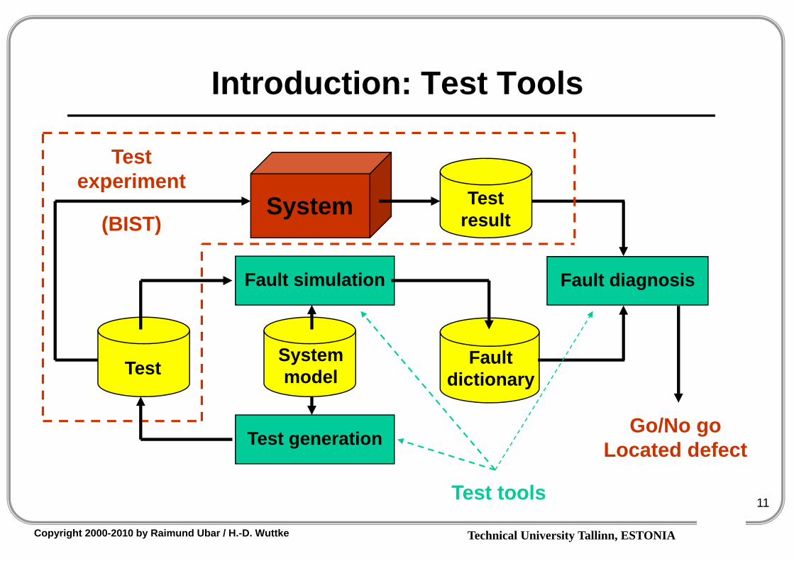
Introduction: Test Tools
System Test result
Fault dictionary
Fault diagnosis
Go/No go Located defect
Test
Test experiment
(BIST)
Test tools
System model
Test generation
Fault simulation

Technical University Tallinn, ESTONIACopyright 2000-2010 by Raimund Ubar / H.-D. Wuttke
12
Overview
1. Introduction2. Theory: Boolean differential algebra3. Theory: Decision diagrams4. Fault modelling5. Test generation6. Fault simulation7. Fault diagnosis8. Testability measuring9. Design for testability10. Built in Self-Test

Technical University Tallinn, ESTONIACopyright 2000-2010 by Raimund Ubar / H.-D. Wuttke
13
Introduction: the Problem is Money?
Cost oftesting
Quality
Cost
Cost ofthe fault
100%0%
Cost of quality
Optimumtest / quality
How to succeed?Try too hard!
How to fail?Try too hard!
(From American Wisdom)
Conclusion:“The problem of testingcan only be containednot solved”
T.Williams
Test coverage function
Time
100%

Technical University Tallinn, ESTONIACopyright 2000-2010 by Raimund Ubar / H.-D. Wuttke
14
Introduction : How Much to Test?
Amusing Test:Paradox 1:
Digital model is finite, analog model is infinite.
However, the complexity problemwas introduced by Digital World
Paradox 2:If I can show that the system works,then it should be not faulty.But, what does it mean: it works?
All life is an experiment.The more experiments you make,the better
(American Wisdom)
SystemStimuli
YResponse
X
Y
X
Samples (for the analog case)
In digital case you cannot extrapolate

Technical University Tallinn, ESTONIACopyright 2000-2010 by Raimund Ubar / H.-D. Wuttke
15
Introduction: How Much to Test?
Paradox 3:• 264 input patterns for 32-bit
accumulator will be not enough
• A short may change the circuit into a sequential one,and you will need 265 input patterns
Time can be your best friendor your worst enemy
(Ray Charles)
& &x1
x2
x3
y State q
Y = F(x1, x2, x3,q)
*1
1
Y = F(x1, x2, x3)Bridging fault
0
264 = 1,8*1019 ~ 600 years (4 GHz)???

Technical University Tallinn, ESTONIACopyright 2000-2010 by Raimund Ubar / H.-D. Wuttke
16
Introduction: How Much to Test?
Paradox 4:
• Mathematicians counted that Intel 8080 needed for exhaustive testing 37 years– Intel 8080 is not existing anymore– Majority of its functions have never used during its lifetime– How to know which functions will not be used?
• Manufacturers are testing microprocessors by only10 seconds
• How to reduce 37 years to 10 sec?

Technical University Tallinn, ESTONIACopyright 2000-2010 by Raimund Ubar / H.-D. Wuttke
17
Two Approaches to Testing
Testing of functions:12
n
Combinational circuit
under test
Truth table:
Patterns
00…00000…001 00…010
…
11…111
Functions
01 01 01…10100 11 00…011 00 00 11…111
…
00 00 00…111 2n
1
1 2n2
Number of patterns
Number of functions
2n-12tested
50%!
0%
Faulty functions
covered by 1. pattern Faulty
functions covered by 2. pattern
50%
75%3. pattern
4. pat. 87,5%
93,75%
100%

Technical University Tallinn, ESTONIACopyright 2000-2010 by Raimund Ubar / H.-D. Wuttke
18
Two Approaches to Testing
Testing of structural faults: 12
n
Combinational circuit
under test
Fault coverage
100%
Number of patterns
4
4. pat.Not tested
faults
Faults covered by 1. pattern
2. pattern
3. patttern

Technical University Tallinn, ESTONIACopyright 2000-2010 by Raimund Ubar / H.-D. Wuttke
19
Two Approaches to Testing
Testing of functions:
100% will be reached onlyafter 2n test patterns
100% will be reached when all faults from the fault list are covered
0%
Faulty functions
covered by 1. pattern Faulty
functions covered by 2. pattern
50%
75%3. pattern
4. pat. 87,5%
93,75%
100%
100%
Testing of faults
Testing of functions
Testing of faults:
4. pat.Not tested
faults
Faults covered by 1. pattern
2. pattern
3. patttern

Technical University Tallinn, ESTONIACopyright 2000-2010 by Raimund Ubar / H.-D. Wuttke
20
Hierarchy vs. Functionality
Hierarchy: Divide and conquer
• Component test:– self-test
• System test:– functional test
Functional test
Self-Test
System

Technical University Tallinn, ESTONIACopyright 2000-2010 by Raimund Ubar / H.-D. Wuttke
21
Self-Test in Digital Systems
SoC
SRAMPeripherial ComponentInterconnect
SRAM
CPU
Wrapper
CoreUnderTest
ROM
MPEG UDLDRAM
Test AccessMechanism
Sink
Test AccessMechanism
Source
SoC
BIST Control Unit
Core Under Test
CUT
Test Pattern Generation
Test Response Analysis
Self-Test (BIST) in a component

Technical University Tallinn, ESTONIACopyright 2000-2010 by Raimund Ubar / H.-D. Wuttke
22
Introduction: Complexity vs. QualityProblems:• Traditional low-level test generation and fault simulation methods and
tools for digital systems have lost their importance because of thecomplexity reasons
• Traditional Stuck-at Fault (SAF) model does not quarantee the quality
• How to improve test quality at increasing complexitiesof today's systems?
Two main trends:– Defect-oriented test and – High-level modelling
• Both trends are caused by the increasing complexities of systems based on deep-submicron technologies

Technical University Tallinn, ESTONIACopyright 2000-2010 by Raimund Ubar / H.-D. Wuttke
23
Introduction: A Compromise• The complexity problem in testing digital systems is handled by
raising the abstraction levels from gate to register-transfer level (RTL) instruction set architecture (ISA) or behavioral levels
– But this moves us even more away from the real life of defects (!)
• To handle defects in circuits implemented in deep-submicron technologies, new defect-oriented fault models and defect-oriented test methods should be used
– But, this is increasing even more the complexity (!)
• As a promising compromise and solution is:To combine hierarchical approachwith defect orientation

Technical University Tallinn, ESTONIACopyright 2000-2010 by Raimund Ubar / H.-D. Wuttke
24
References1. N.Nicolici, B.M. Al-Hashimi. Power-Constrained Testing of VLSI Circuits.
Kluwer Acad. Publishers, 2003, 178 p. 2. R.Rajsuman. System-on-a-Chip. Design and Test. Artech House, Boston,
London, 2000, 277 p. 3. S.Mourad, Y.Zorian. Principles of Testing Electronic Systems. J.Wiley &
Sons, Inc. New York, 2000, 420 p. 4. M.L.Bushnell, V.D.Agrawal. Essentials of Electronic testing. Kluwer Acad.
Publishers, 2000, 690 p. 5. A.L.Crouch. Design for Test. Prentice Hall, 1999, 349 p. 6. S. Minato. Binary Decision Diagrams and Applications for VLSI CAD.
Kluwer Academic Publishers, 1996, 141 p.7. M. Abramovici et. al. Digital Systems Testing & Testable Designs.
Computer Science Press, 1995, 653 p. 8. D. Pradhan. Fault-Tolerant Computer System Design. Prentice Hall,1995,
550 p.

Technical University Tallinn, ESTONIACopyright 2000-2010 by Raimund Ubar / H.-D. Wuttke
25
Overview
1. Introduction
2. Theory: Boolean differential algebra3. Theory: Decision diagrams4. Fault modelling5. Test generation6. Fault simulation7. Fault diagnosis8. Testability measuring9. Design for testability10. Built in Self-Test

Technical University Tallinn, ESTONIACopyright 2000-2010 by Raimund Ubar / H.-D. Wuttke
26
Faults as Test Objectives
Stuck-at 1 fault
&&
1
X1 = 1
X3 = 0 1
y = 0 1X2 = 1
1 0(x3 = 0 1) (y = 0 1)
Output is depending on input change
Y = F(X) = x1 x2 x3
dx3 dyHow to set up the dependency:

Technical University Tallinn, ESTONIACopyright 2000-2010 by Raimund Ubar / H.-D. Wuttke
27
Boolean Derivatives
1)(
ixxF
0)(
ixxF
Traditional algebra: speed Boolean algebra: change
F(x) will changeif xi changes
F(x) will not change
if xi changes
y 0,1, F(x) 0,1y
x
y = F(x)
0)(
ixxF
0)(
xXF

Technical University Tallinn, ESTONIACopyright 2000-2010 by Raimund Ubar / H.-D. Wuttke
28
Boolean Derivatives: Definition
Boolean function:
Y = F(x) = F(x1, x2, … , xn)Boolean partial derivative:
),...,...(),...,...()(11 nini
i
xxxFxxxFx
xF
),...0,...(),...1,...()(11 nini
i
xxxFxxxFx
xF

Technical University Tallinn, ESTONIACopyright 2000-2010 by Raimund Ubar / H.-D. Wuttke
29
Boolean Derivatives: Main Properties
Useful properties of Boolean derivatives:
These properties allow to simplify the Boolean differential equation
to be solved for generating test pattern for a fault at xi
If F(x) is independent of xi
ii xxGxF
xxGxF
)()()()(
ii xxGxF
xxGxF
)()()()(

Technical University Tallinn, ESTONIACopyright 2000-2010 by Raimund Ubar / H.-D. Wuttke
30
Boolean Derivatives (x5): Calculation
316254142321 )))((( xxxxxxxxxxxxy
5
562414233121
5
625414233121
5
625414233121
5
625414233121
5
625414233121
5
))((
)))(((
)))(((
))))((((
xxxxxxxxxxxxx
xxxxxxxxxxxxx
xxxxxxxxxxxxx
xxxxxxxxxxxxx
xxxxxxxxxxxxx
xy
Transformations of the Boolean derivative:
Given:

Technical University Tallinn, ESTONIACopyright 2000-2010 by Raimund Ubar / H.-D. Wuttke
31
Boolean Derivatives (x5): Calculation
316254142321 )))((( xxxxxxxxxxxxy
5
562414233121
5 xxxxxxxxxxxxx
xy
Transformations of the Boolean derivative:
Given:
12341346624142331215
xxxxxxxxxxxxxxxxxxxxy
Minimization of the Boolean derivative:
[0,.,0,1,-,0 ] oder [-,.,0,1,1,0 ]
Belegungsvektor der Variablen außer x5 [ x6 , . , x4, x3, x2, x1 ]

Technical University Tallinn, ESTONIACopyright 2000-2010 by Raimund Ubar / H.-D. Wuttke
32
Boolean Derivatives (x5): Calculation
316254142321 )))((( xxxxxxxxxxxxy
5
562414233121
5 xxxxxxxxxxxxx
xy
Transformations of the Boolean derivative:
Given:
12341346624142331215
xxxxxxxxxxxxxxxxxxxxy
Minimization of the Boolean derivative:
Belegung der Variablen außer x5 [ x6 , . , x4, x3, x2, x1 ]

Technical University Tallinn, ESTONIACopyright 2000-2010 by Raimund Ubar / H.-D. Wuttke
33
Overview
1. Introduction2. Theory: Boolean differential algebra
3. Theory: Decision diagrams4. Fault modelling5. Test generation6. Fault simulation7. Fault diagnosis8. Testability measuring9. Design for testability10. Built in Self-Test

Technical University Tallinn, ESTONIACopyright 2000-2010 by Raimund Ubar / H.-D. Wuttke
34
Binary Decision Diagrams
Shannon’s Theorem:
01)()(
)(
kk xkxk xFxxFx
xFy
xky1
)(kx
xF
0)(
kxxF
Using the Theoremfor BDD synthesis:
Functional synthesis BDDs:
43124321 ))(( xxxxxxxxy
x1y 2432 )( xxxx x2
x3 x4
43xxx3
x4
43 xx
Example:

Technical University Tallinn, ESTONIACopyright 2000-2010 by Raimund Ubar / H.-D. Wuttke
35
Binary Decision Diagrams
7654321 )( xxxxxxxy
Simulation (path in the BDD):
7654321 xxxxxxx0 1 1 0 1 0 0
1y
Boolean derivative:
15427613
xxxxxxxy
y x1
x2 x3
x4 x5
x6 x7
0
11
0Functional BDD

Technical University Tallinn, ESTONIACopyright 2000-2010 by Raimund Ubar / H.-D. Wuttke
36
Basics of Theory for Test and Diagnostics
Two basic tasks:1. Which test patterns are needed to detect a fault (or all faults)2. Which faults are detected by a given test (or by all tests)
ALU
&10
0
&1 0
Gate
Multiplier
System Booleandifferential
algebra
Decisiondiagrams
DD
BDD

Technical University Tallinn, ESTONIACopyright 2000-2010 by Raimund Ubar / H.-D. Wuttke
37
Fault Propagation Problem
&1
Path activation
Fault “Stuck-at-1”
0
Fault activation
Correct signal
Error
1 0
Logic gate
1
Pathactivation
FaultStuck-at-0
Fault activation
Correct signal
Error
1 0
7654321 )( xxxxxxxy
x1x2
x3 = 1x4x5x6x7
y
0
0
0 F (X)
Logic circuit

Technical University Tallinn, ESTONIACopyright 2000-2010 by Raimund Ubar / H.-D. Wuttke
38
Fault Propagation with BDD
1
Pathactivation
FaultStuck-at-0
Fault activation
Correct signal
Error
1 0
7654321 )( xxxxxxxy
x1x2
x3 = 1x4x5x6x7
y
0
0
0 F (X)
x1
x2
y
x3
x4 x5
x6 x7
0
11x1
x2
y
x3
x4 x5
x6 x7
0
11
0
Fault propagation through logic circuit with BDD:
0
0
?1
?

Technical University Tallinn, ESTONIACopyright 2000-2010 by Raimund Ubar / H.-D. Wuttke
39
BDDs for Logic GatesElementary BDDs:
1
x1x2x3
y x1 x2 x3&
x2x3
y x1
x1
x2
x3
1x1x2x3
y x1 x2 x3
+x1x2x3
y
x1
x2
x3
y x2 x3
Adder
NOR
AND
OR

Technical University Tallinn, ESTONIACopyright 2000-2010 by Raimund Ubar / H.-D. Wuttke
40
BDDs for Flip_Flops
DC
q c
q’
D
SC
q
R
0')'(
SRqcRqScq
c
q’
S
R q’
R
U
D Flip-Flop
RS Flip-Flop
JK Flip-FlopSJ
q
R c
q’
S
R q’
CK
K
J
U - unknown value

Technical University Tallinn, ESTONIACopyright 2000-2010 by Raimund Ubar / H.-D. Wuttke
41
Fragen