s280-42-1 nova three-phase recloser instructions · recloser and inspect it thoroughly for damage...
TRANSCRIPT

Types NOVA 15, NOVA 27, and NOVA 38; Three-Phase Microprocessor-Controlled; Installation and Operation Instructions
ReclosersService Information
Safety Information ..................................................... 2
Hazard Statement Definitions ................................. 2
Safety Instructions .................................................. 2
Product Information .................................................. 3
Introduction ............................................................ 3
Acceptance and Initial Inspection ........................... 3
Handling and Storage .............................................. 3
Standards .............................................................. 3
Description of Operation ......................................... 3
Ratings and Specifications ....................................... 4
Check Recloser Ratings Prior to Installation ........... 4
Dimensions ................................................................ 5
NOVA Mechanism Interface Options ....................... 6
Control-Powered Interface ..................................... 6
Auxiliary-Powered Interface ..................................... 7
Installation Procedure ............................................... 8
Moving the Recloser ............................................... 8
Lifting the Recloser ................................................. 8
Remove Recloser from Service .............................. 11
Grounding the NOVA Recloser ............................... 11
Operation ................................................................... 14
Electrical Operation ................................................ 14
OPEN/CLOSE Contact Position Indicator ............... 14
Hotstick Operation (Manual Open, Electrical Close) ..... 14
Internal Voltage Sensing Option .............................. 15
Accessories ............................................................... 19
Auxiliary Switch ....................................................... 19
Terminals ................................................................ 19
Pole-Mounting Hanger ........................................... 20
Arrester-Mounting Brackets ................................... 21
Substation-Mounting Frame ................................... 22
Service Information ................................................... 23
Service Requirements ............................................ 23
Frequency of Inspection ......................................... 23
Testing Operation ................................................... 23
High-Potential Withstand Testing ........................... 24
Module Flashover Service ....................................... 25
Troubleshooting ........................................................ 25
Unit Will Not Close ................................................. 25
Unit Will Not Open Electrically ................................ 25
Contents
S280-42-1
1
NOVA 15 for Serial Number CP571297544 and above
Figure 1.NOVA three-phase, microprocessor-controlled recloser, shown with two-hole, flat-pad accessory.

2
Type NOVA Three-Phase, Microprocessor-Controlled Recloser Installation and Operation Instructions
The instructions in this manual are not intended as a substitute for proper training or adequate experience in the safe operation of the equipment described. Only com-petent technicians who are familiar with this equipment should install, operate, and service it.
A competent technician has these qualifications:
Following is important safety information. For safe installa-tion and operation of this equipment, be sure to read and under stand all cautions and warnings.
Safety InstructionsFollowing are general caution and warning statements that apply to this equipment. Additional statements, related to specific tasks and procedures, are located throughout the manual.
SAFETY INFORMATION
SAFETY FOR LIFE Cooper Power Systems products meet or exceed all applicable industry standards relating to product safety. We actively pro-mote safe practices in the use and maintenance of our products through our service literature, instructional training programs, and the continuous efforts of all Cooper Power Systems employees involved in product design, manufacture, marketing, and service.
We strongly urge that you always follow all locally approved safety procedures and safety instructions when working around high voltage lines and equipment and support our “Safety For Life” mission.
This manual may contain four types of hazard state-ment:
DANGER: Indicates an imminently hazard-ous situation which, if not avoided, will
result in death or serious injur.
WARNING: Indicates a potentially hazard-ous situation which, if not avoided, could
result in death or serious injury.
CAUTION: Indicates a potentially hazard-ous situation which, if not avoided, may
result in minor or moderate injury.
CAUTION: Indicates a potentially hazardous situation which, if not avoided, may result in equipment damage only.
Hazard Statement Definitions
SAFETYFOR LIFE
SAFETYFOR LIFE
WARNING:This equipment is not intended to protect human life. Follow all locally approved procedures and safety practices when installing or operating this equipment. Failure to comply may result in death, severe personal injury, and equipment damage. G102.1
DANGER:Hazardous voltage. Contact with hazardous voltage will cause death or severe personal injury. Follow all locally approved safety procedures when working around high- and low-voltage lines and equipment.
WARNING:Before installing, operating, maintaining, or testing this equipment, carefully read and understand the contents of this manual. Improper operation, handling, or maintenance can result in death, severe personal injury, and equipment damage. G101.0
WARNING:Power distribution and transmission equipment must be properly selected for the intended application. It must be installed and serviced by competent personnel who have been trained and understand proper safety proce-dures. These instructions are written for such personnel and are not a substitute for adequate training and expe-rience in safety procedures. Failure to properly select, install, or maintain power distribution and transmission equipment can result in death, severe personal injury, and equipment damage.

Introduction provides installation, oper-
ation, and service instructions for the Type NOVA™ three-phase, microprocessor-controlled recloser. Before install-ing and operating this recloser, carefully read and under-stand the contents of this manual.
Read This Manual FirstRead and understand the contents of this manual and fol-low all locally approved procedures and safety practices before installing or operating this equipment. This recloser is used in conjunction with a Cooper Power Systems microprocessor-based recloser control.
If used with a Form 4C control, refer to .
If used with a Form 4D Pole Mount control, refer to .
If used with a Form 5 control, refer to .
.
.
.
If used with an FXB control, refer to .
The NOVA recloser with Type A mechanism/control-powered interface is not compatible with the FXB control.
The NOVA recloser is not compatible with the Form 2,
Additional InformationThese instructions cannot cover all details or vari ations in the equipment, procedures, or process described nor provide directions for meeting every possible contin gency during installation, operation, or maintenance. For addi-tional information, contact your Cooper Power Systems representative.
Acceptance and Initial InspectionEach recloser is completely assembled, tested, and inspected at the factory. It is in good condition when accepted by the carrier for shipment. Upon receipt, inspect the shipping container for signs of damage. Unpack the recloser and inspect it thoroughly for damage incurred dur-ing shipment. If damage is discovered, file a claim with the carrier immediately.
Handling and StorageBe careful during handling and storage of the recloser to minimize the possibility of damage. Refer to the Moving the Recloser and Lifting the Recloser sections. If the recloser is to be stored for any length of time prior to instal-lation, provide a clean, dry storage area.
Cooper Power Systems recommends transporting NOVA reclosers in the closed position to maximize the operational performance of the unit.
StandardsThe Type NOVA reclosers are designed and tested in accordance with:
™
™
Quality StandardsISO 9001 Certified Quality Management System
Description of OperationThe Type NOVA recloser is a three-phase, vacuum-interrupting recloser designed for electrical distribution
and tested to be compatible with Cooper Power System control types. The Type NOVA recloser is available with two configuration options: control-powered interface and auxiliary-powered interface.
The solid polymer insulation system does not rely on a gas-eous, liquid, or foam dielectric. The NOVA recloser is highly resistant to ozone, oxygen, moisture, contamination, and ultraviolet light. The NOVA recloser has three solid-polymer interrupter modules, an embedded current transformer, and a standard aluminum mechanism housing. It is suit-able for operation through a temperature range of -40°C to +55°C.
S280-42-1
3
SAFETYFOR LIFE
PRODUCT INFORMATION
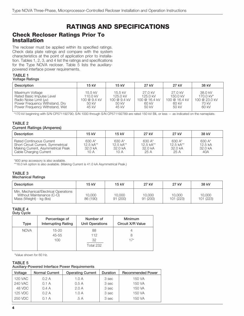
Check Recloser Ratings Prior To InstallationThe recloser must be applied within its specified ratings. Check data plate ratings and compare with the system characteristics at the point of application prior to installa-
for the Type NOVA recloser. Table 5 lists the auxiliary-powered interface power requirements.
Type NOVA Three-Phase, Microprocessor-Controlled Recloser Installation and Operation Instructions
4
RATINGS AND SPECIFICATIONS
TABLE 5Auxiliary-Powered Interface Power Requirements
Voltage Normal Current Operating Current Duration Recommended Power
TABLE 4Duty Cycle
Percentage of Number of Minimum Type Interrupting Rating Unit Operations Circuit X/R Value
NOVA 15-20 88 4
45-55 112 8
*
Description 15 kV 15 kV 27 kV 27 kV 38 kV
Min. Mechanical/Electrical Operations Without Maintenance (C-O) 10,000 10,000 10,000 10,000 10,000
TABLE 3Mechanical Ratings
Description 15 kV 15 kV 27 kV 27 kV 38 kV
Rated Basic Impulse Level 110.0 kV 125.0 kV 125.0 kV 150.0 kV 170.0 kV*
TABLE 1Voltage Ratings
*170 kV beginning with S/N CP571192790; S/N 1000 through S/N CP571192789 are rated 150 kV BIL or less — as indicated on the nameplate.
*800 amp accessory is also available.
Description 15 kV 15 kV 27 kV 27 kV 38 kV
Short Circuit Current, Symmetrical 12.5 kA** 12.5 kA** 12.5 kA** 12.5 kA** 12.5 kA
Cable Charging Current 10 A 10 A 25 A 25 A 40A
TABLE 2Current Ratings (Amperes)

S280-42-1
5
SAFETYFOR LIFE
DIMENSIONS
Figure 2.Type NOVA recloser dimensions, NOVA 27 shown.
Description 15 kV 15 kV 27 kV 27 kV 38 kV 110 kV BIL 125 kV BIL 125 kV BIL 150 kV BIL 170 kV BIL
Terminal to terminal 1040 1040 1040 1040 1040
(40.9) (40.9) (40.9) (40.9) (40.9)
Creepage Distances
B C
NOVA 15 791 508
NOVA 15
NOVA 27
NOVA 27
NOVA 38
Terminal Options A
Eyebolt,
Eyebolt, 4/0 - 1000 mcm 108 (4.25)
Cable Range (800 A maximum)
Flat Pad, 2-hole 114 (4.5)
Flat Pad, 4-hole 121 (4.75)
(800 A maximum)
Stud Type, 1.125 - 12 threads (800 A maximum)
285
(11.25)
Terminal Connectors
1/0 - 500 MCM(Standard)
Terminal Connectors
1/0 - 500 MCM(Standard)
A
271
(10.75)
1000
(39.50)
285
(11.25)
OP
EN
B
C
388
(15.5)
388
(15.5)
A
A
413
(16.25)
CLOSED
NOTE: All dimensions are mm (inches). Dimensions shown are approximate.

Control-Powered InterfaceThe Type NOVA recloser mechanism with the control-powered interface is fully operational with Cooper Power
based controls equipped with the required DC-to-DC con-verter, interface circuit, and a fully shielded 19-pin cable.
The control-powered interface includes a 19-pin receptacle on the recloser and internal heaters (for humidity control) powered from the control input power supply (AC or DC).
Control-powered NOVA reclosers manufactured after September 2004 require a Voltage Trip/Close (VTC) inter-face and a VTC-ready control for tripping and closing. This VTC requirement applies to three-phase, control-powered NOVA reclosers with serial numbers 100,000 and above
Control-powered NOVA reclosers with serial numbers below 100,000 do not require a VTC-ready control. Refer to the recloser nameplate for the serial number.
The DC-to-DC converter board converts the control’s 24
capacitors in the NOVA mechanism. The DC-to-DC con-verter board also houses voltage monitoring and condition-ing circuits that protect the battery from failure and provide trip/close operations without AC power. In the absence of AC power to the electronic control, the control battery will provide the trip and close operations. A complete four-trip sequence with minimal reclose intervals as configured for each control is obtainable without AC power. The recloser and control system is capable of exceeding over one thou-sand operations on battery power only.
Type NOVA Three-Phase, Microprocessor-Controlled Recloser Installation and Operation Instructions
6
Electronic
Control
Potential
Transformer
(120/240 VAC)
120/240 VAC
Power Cable19-Pin
Control Cable
OP
EN
CLOSED
Figure 3.Control-powered NOVA recloser configuration with potential transformer input power.
NOVA MECHANISM INTERFACE OPTIONS
TABLE 6Serial Number Break for Control-Powered NOVA Reclosers with VTC
Control-Powered NOVA Serial No. Recloser
NOVA 15 100,000 CP57#######
NOVA 27 100,000 CP57#######
CP57#######
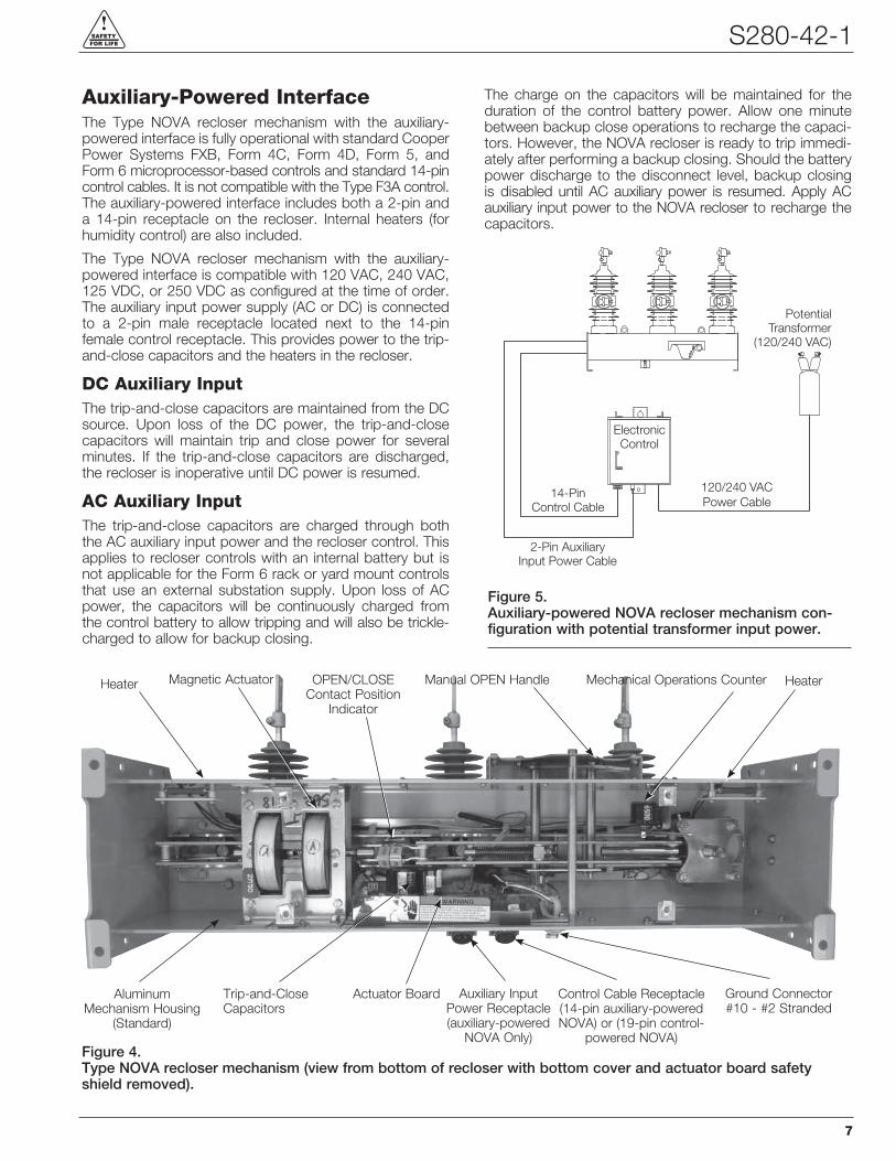
Auxiliary-Powered InterfaceThe Type NOVA recloser mechanism with the auxiliary-powered interface is fully operational with standard Cooper Power Systems FXB, Form 4C, Form 4D, Form 5, and
The auxiliary-powered interface includes both a 2-pin and a 14-pin receptacle on the recloser. Internal heaters (for humidity control) are also included.
The Type NOVA recloser mechanism with the auxiliary-powered interface is compatible with 120 VAC, 240 VAC, 125 VDC, or 250 VDC as configured at the time of order. The auxiliary input power supply (AC or DC) is connected to a 2-pin male receptacle located next to the 14-pin female control receptacle. This provides power to the trip-and-close capacitors and the heaters in the recloser.
DC Auxiliary InputThe trip-and-close capacitors are maintained from the DC source. Upon loss of the DC power, the trip-and-close capacitors will maintain trip and close power for several minutes. If the trip-and-close capacitors are discharged, the recloser is inoperative until DC power is resumed.
AC Auxiliary InputThe trip-and-close capacitors are charged through both the AC auxiliary input power and the recloser control. This applies to recloser controls with an internal battery but is
that use an external substation supply. Upon loss of AC power, the capacitors will be continuously charged from the control battery to allow tripping and will also be trickle-charged to allow for backup closing.
The charge on the capacitors will be maintained for the duration of the control battery power. Allow one minute between backup close operations to recharge the capaci-tors. However, the NOVA recloser is ready to trip immedi-ately after performing a backup closing. Should the battery power discharge to the disconnect level, backup closing is disabled until AC auxiliary power is resumed. Apply AC auxiliary input power to the NOVA recloser to recharge the capacitors.
S280-42-1
7
SAFETYFOR LIFE
Electronic
Control
120/240 VAC
Power Cable14-Pin
Control Cable
OP
EN
2-Pin Auxiliary
Input Power Cable
Potential
Transformer
(120/240 VAC)
Figure 5.Auxiliary-powered NOVA recloser mechanism con-figuration with potential transformer input power.
Figure 4. Type NOVA recloser mechanism (view from bottom of recloser with bottom cover and actuator board safety shield removed).
Manual OPEN Handle Mechanical Operations CounterOPEN/CLOSEContact Position
Indicator
Heater Magnetic Actuator
Trip-and-Close Capacitors
Actuator Board Auxiliary Input Power Receptacle (auxiliary-powered
NOVA Only)
Ground Connector#10 - #2 Stranded
Control Cable Receptacle (14-pin auxiliary-powered NOVA) or (19-pin control-
powered NOVA)
Aluminum Mechanism Housing
(Standard)
Heater

When installing the recloser, refer to the applicable recloser-mounting frame instructions. Installation instructions are included with the mounting frame.
1. Check the data plate ratings. Make sure the rat-ings, settings, and interface options on the recloser data plate (Table 7 and Figure 14) are correct for the planned installation.
2. Perform high-potential withstand tests. Prior to installing the NOVA recloser, perform high-potential withstand tests. Refer to the Service Information sec-tion for high-potential withstand test procedures.
3. Install the recloser. Install the recloser in the appro-priate Cooper Power Systems pole- or substation-
instructions.
open the unit by lowering the yellow handle.
Type NOVA Three-Phase, Microprocessor-Controlled Recloser Installation and Operation Instructions
8
WARNING: This equipment is not intended to protect human life. Follow all locally approved
procedures and safety practices when installing or operating this equipment. Failure to comply can result in death, severe personal injury, and equipment damage. G102.1
WARNING: Hazardous voltage. Always use a hotstick when working with this equipment. Failure
to do so could result in contact with high voltage, which will cause death or severe personal injury. G108.1
CAUTION: Follow all locally approved safety practices when lifting and mounting the equipment. Use the lifting lugs provided. Lift the unit smoothly and do not allow the unit to shift. Improper lifting can result in equipment damage.
CAUTION: Personal injury. Sheds on epoxy encapsulation have sharp edges. Wear protective
gloves when handling the unit. Failure to do so can result in cuts and abrasions. T258.1
INSTALLATION PROCEDURE
TABLE 7Nameplate StampingSerial number format: CP57######Y
Stamping Option YAuxiliary-Powered Interface 48 VDC Interface Input / 48 VDC Heater A
125 VDC Interface Input / 125 VDC Heater D
250 VDC Interface Input / 250 VDC Heater E
120 VAC Interface Input / 120 VAC Heater H
240 VAC Interface Input / 240 VAC Heater J
Control-Powered Interface 120 VAC Heater B
240 VAC Heater C
Figure 6.Moving and lifting the Type NOVA recloser.
OP
EN
A
Cg
B
LiftingLugs
Moving the RecloserType NOVA reclosers are shipped palletized (bolted onto a pallet). When moving with a fork truck/lift, the recloser must remain bolted to the pallet to avoid damage to the OPEN/CLOSE contact position indicator.
Cooper Power Systems recommends transporting NOVA reclosers in the closed position to maximize the operational performance of the unit.
Lifting the RecloserFollow all approved safety practices when making hitch-es and lifting the equipment. Lift the unit smoothly and do not allow the unit to shift.
A:
B: Center of gravity (Cg) is approximately 100 mm (4 in) below plane of
lower terminals.
CAUTION: Tip-over Hazard. High center of grav-ity. Use a 4-point hitch to prevent switchgear from
overturning during lifting operations. Improper lifting can result in personal injury or equipment damage. T297.0

4. Ground the recloser. Make the ground connection to the ground connector. The ground connector is located on the back of the mechanism housing.
ground clamp accepts #10 to #2 stranded cables.
grounding for the Type NOVA recloser.
5. Install the control. Refer to the control installation manual and install the control. Make sure the control cable is connected between the control and the reclos-er, the control is properly programmed for the planned installation, and the control is grounded.
To ensure proper installation of this cable, securely fasten the aluminum cable coupler ring (Figure 7).
Control-powered NOVA reclosers manufactured after September 2004 require a Voltage Trip/Close (VTC) interface and a VTC-ready control for tripping and closing. This VTC requirement applies to three-phase, control-powered NOVA reclosers with a Type A or Type D mechanism with serial numbers 100,000 and above or beginning with the characters CP57. They can be identified by labels prominently displayed on the bottom of the recloser tank and on the side near the 19-pin receptacle, as shown in Figure 8. Control-powered NOVA reclosers with serial numbers below 100,000 do not require a VTC-ready control. Refer to the recloser nameplate for the serial number.
(continued on next page)
S280-42-1
9
SAFETYFOR LIFE
WARNING: Hazardous voltage. Solidly ground all equipment. Failure to comply can result in death,
severe personal injury, and equipment damage.
Figure 8.Control-powered NOVA recloser VTC labels.
CAUTION: Equipment misoperation. The control-powered NOVA reclosers that require a VTC
interface must be used with VTC-ready controls. Failure to use a VTC-ready control will result in failure to trip or close. G144.0
Figure 7.Cable with aluminum cable coupler ring.

6. Make high-voltage line connections (refer to Figures 9 and 10).
Note: Disconnect switches and bypass switches are not required, but are highly recommended as they facili-tate switching and isolation.
A. Connect high-voltage lines to recloser bushing terminals.
The recommended torque value for bushing termi--
cable to soft-drawn and hard-drawn copper as well as applicable wire sizes, solid wire, and stranded wire.
NOTICE: Equipment damage may occur when
disconnecting wires to the recloser terminals
Refer to Figure 10 for terminal identification of the NOVA recloser.
Terminal connection to copper conductors only are recommended.
To rotate a flat-pad or eyebolt bushing terminal prior to connecting power line leads, loosen the pinch bolt on the terminals.
After rotating the terminal, retighten the pinch bolt as follows:
B. Provide surge arrester protection. Surge arrester protection should be provided on both sides; refer to Figure 9.
Type NOVA Three-Phase, Microprocessor-Controlled Recloser Installation and Operation Instructions
10
SurgeArresters
BypassSwitch
DisconnectSwitch
SurgeArresters
DisconnectSwitch
1
3
5
2
4
6
Figure 9.Connection diagram shows complete surge protec-tion and illustrates bypass and disconnect switches.
CAUTION: Equipment Damage. Do not adjust or rotate bushing terminals without first removing power line leads and loosening pinch bolt to release clamp tension. Failure to remove tension between the clamp and the interrupter stud prior to rotating the terminal will dam-age the encapsulated interrupter assembly resulting in equipment damage.
OP
EN
6 4 2
5 3 1
Figure 10.Terminal identification of Type NOVA recloser.
IMPORTANT: The default connections use the horizon-tal bushing as the source side and the vertical bushing as the load side. Also, the horizontal bushing may be used as the load side and the vertical bushing as the source side. Note that reversing the source and load bushings has no effect on overcurrent protection but may require setting or wiring changes to the control for correct metering.
If equipped with internal voltage sensors, the horizontal
internal voltage sensors cannot monitor source-side volt-age when the NOVA recloser is in the OPEN position if the horizontal bushings are connected to the load.
CAUTION: Equipment damage may occur if torque values are exceeded.

Remove Recloser from Service 1. Block ground tripping via the control panel. Refer to the
instructions for the control connected to the recloser.
2. Close all three bypass switches.
3. Pull down the yellow operating handle with a hotstick. The yellow operating handle is located under the recloser sleet hood.
The control will sense that the recloser is open and provide OPEN/LOCKOUT indication on the front panel.
4. Open the source and load disconnect switches.
5. Disconnect the control battery.
6. Remove the control AC sensing and power connec-tions from the control using a separate disconnect switch.
7. Disconnect the control cable from the recloser.
8. Follow standard utility procedures regarding removal of recloser from service.
NOVA reclosers in the closed position to maximize the operational performance of the unit.
Grounding the NOVA Recloser
3-Wire Ungrounded and Impedance Grounded SystemsThe use of a grounding mat may be required depending upon the local safety regulations defining the permissible step and touch potential levels. Consult local regulations for proper grounding procedures.
S280-42-1
11
SAFETYFOR LIFE
IMPORTANT: In pole-mounted applications, a ground connection must be made between the recloser, trans-former, recloser control, and SCADA equipment for proper protection of the equipment. The pole ground must be sized per local utility practices to minimize the impedance between the recloser and the control.
IMPORTANT: All external inputs to the control must be routed within 8 inches of their corresponding ground. During a surge, a potential of approximately 1.5 kV per foot can develop in the conductors. Differences between conductor and ground path lengths can add additional stress to the control components in the event of a power surge.
IMPORTANT: Any external voltage sensor installed with the NOVA recloser must have its ground referenced to the recloser ground.
IMPORTANT: Disconnect switches for AC sensing and power connections are necessary to isolate the control for testing and servicing.
CAUTION: Equipment misoperation. Disconnect all control power sources prior to disconnecting or recon-necting the control cable from the control. Failure to comply can result in recloser misoperation at the time of disconnection or reconnection of the control cable to the control.
CAUTION: Hazardous voltage. Open CT second-aries can generate high voltages. Contact with CT
pins of the disconnected cable can cause electric shock and may result in personal injury. Open recloser contacts and open disconnect switches before disconnecting control cable.
CAUTION: Hazardous voltage. Cable conductors
VAC potential while connected to the control. Contact with any pins at the end of the cable directly or indirectly connected to a control can result in personal injury or equipment damage. Disconnect battery and external power sources in the control then remove control cable at control end before disconnecting from recloser end.

Grounding with a Local Supply Voltage Transformer: 4-Wire Multi-Grounded, 3-Wire Ungrounded, or Impedance-GroundedInstallation with a local supply voltage transformer must include the following (refer to Figure 11):
transformer with lightning arresters.
Grounding with a Remote Supply Voltage Transformer: 4-Wire Multi-Grounded, 3-Wire Ungrounded, or Impedance-GroundedInstallation with a remote supply voltage transformer must include the following (refer to Figure 12):
transformer with lightning arresters.
Type NOVA Three-Phase, Microprocessor-Controlled Recloser Installation and Operation Instructions
12
GROUND TIE
POLE
SURGEARRESTER
SUPPLY VOLTAGE(12 GAUGE MINIMUM)
ARRESTERGROUND
SURGEARRESTER
KYLECONTROL
POLE
ACNEUGRD
NE
UA
C
INPUT TERMINALBLOCK
CONTROL CABLE(S)
ARRESTERGROUND
CUSTOMER GROUND CONNECTIONAT EXTERNAL LUG
SURGEARRESTER
NOVA RECLOSER
RECLOSERGROUND
CONNECTOR
TRANSFORMER
POLE GROUND(6 GAUGE MINIMUM)
NOTE: Distance betweentransformer and recloser should be one pole span or less.
Figure 12.Recommended grounding method for NOVA reclos-ers with Cooper microprocessor-based control and remote supply voltage transformer.
TRANSFORMER
SURGEARRESTER
POLE
SUPPLY VOLTAGE(14 GAUGE MINIMUM)
POLE GROUND(6 GAUGE MINIMUM)
KYLECONTROL
CUSTOMER GROUND CONNECTIONAT EXTERNAL LUG
NE
UA
C
GNDNEUAC
INPUTTERMINALBLOCK
CONTROLCABLE(S)
RECLOSERGROUND
CONNECTOR
NOVA RECLOSER
ARRESTERGROUND
SURGEARRESTER
ARRESTERGROUND
SURGEARRESTER
Figure 11.Recommended grounding method for NOVA recloser with Cooper microprocessor-based control and local supply voltage transformer.

transformer with lightning arresters.
S280-42-1
13
SAFETYFOR LIFE
Grounding on a 3-Wire Uni-Grounded System
TRANSFORMER500 VA SUPPLY MINIMUM
SURGEARRESTER
POLE
SUPPLY VOLTAGE(14 GAUGE MINIMUM)
POLE GROUND(6 GAUGE MINIMUM)
KYLECONTROL
CUSTOMER GROUNDCONNECTION
AT EXTERNAL LUG
NE
UA
C
GNDNEUAC
INPUTTERMINAL
BLOCK
CONTROLCABLE(S)
RECLOSERGROUND
CONNECTOR
NOVA RECLOSER
ARRESTERGROUND
SURGEARRESTER
ARRESTERGROUND
SURGEARRESTER
Control Height must be 3 Meters (10 feet) min.
above earth.
Figure 13.Recommended grounding method for NOVA reclosers with Cooper microprocessor-based control on a 3-wire uni-grounded system.
IMPORTANT: In pole-mounted applications, a ground connection must be made between the recloser, trans-former, recloser control, and SCADA equipment for proper protection of the equipment. The pole ground must be sized per local utility practices to minimize the impedance between the recloser and the control.
IMPORTANT: All external inputs to the control must be routed within 8 inches of their corresponding ground. During a surge, a potential of approximately 1.5 kV per foot can develop in the conductors. Differences between conductor and ground path lengths can add additional stress to the control components in the event of a power surge.
WARNING: Hazardous Voltage. Use locally approved operator safety procedures for proper
insulation when maintaining this equipment. High voltage step and touch potential is characteristic in uni-ground systems. Failure to comply can cause death or severe personal injury.
CAUTION: Exported Potential. Do not make direct electrical connections to remote devices. All SCADA
equipment must be mounted locally or connected using the fiber-optic or radio communication accessory. Direct connections to remote devices can produce exported potential causing equipment damage or personal injury.
CAUTION: Hazardous Voltage. Do not use a shared low-voltage network to power the recloser control unless the network is specifically designed to withstand maximum ground potential rise. Ground faults on a high-voltage network can create a rise in ground potential.
Type NOVA Three-Phase, Microprocessor-Controlled Recloser Installation and Operation Instructions
14
Electrical OperationThe Type NOVA recloser utilizes an interface circuit located in the mechanism housing. The electronic interface circuit controls the opening and closing signals to the magnetic actuator. Both control-powered and auxiliary-powered
28 for wiring diagrams.
OPEN/CLOSE Contact Position Indicator
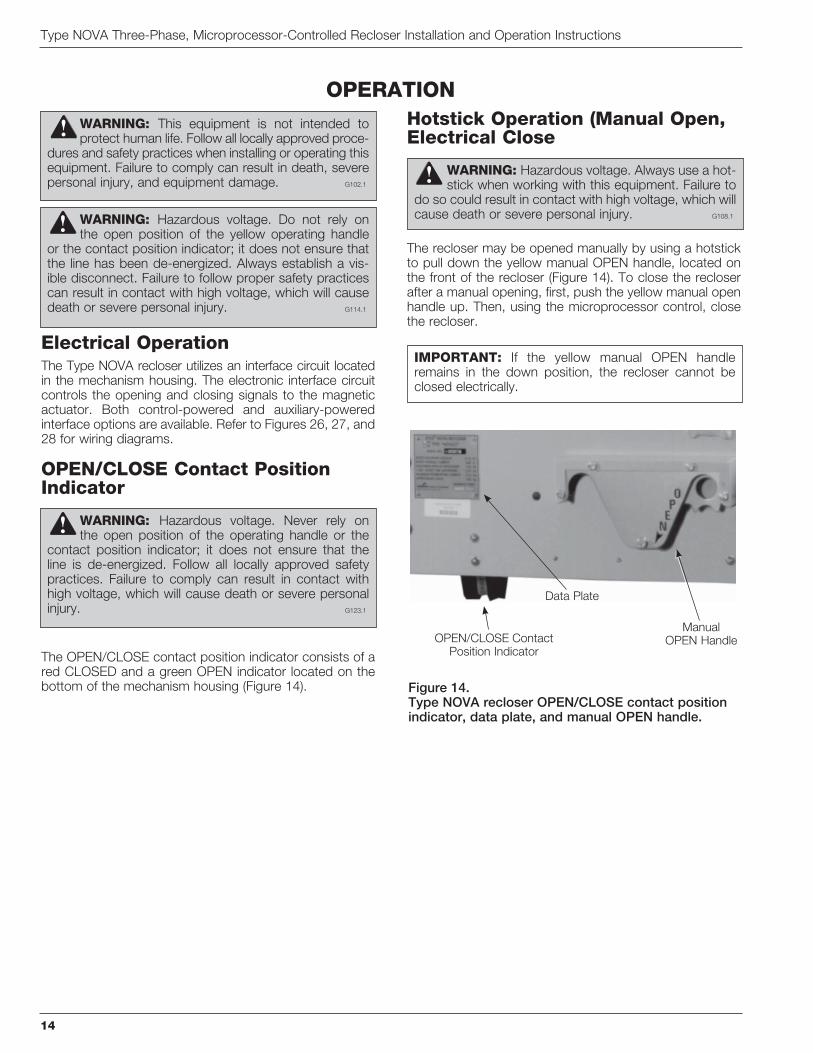
The OPEN/CLOSE contact position indicator consists of a red CLOSED and a green OPEN indicator located on the bottom of the mechanism housing (Figure 14).
Hotstick Operation (Manual Open, Electrical Close
The recloser may be opened manually by using a hotstick to pull down the yellow manual OPEN handle, located on the front of the recloser (Figure 14). To close the recloser after a manual opening, first, push the yellow manual open handle up. Then, using the microprocessor control, close the recloser.
WARNING: This equipment is not intended to protect human life. Follow all locally approved proce-
dures and safety practices when installing or operating this equipment. Failure to comply can result in death, severe personal injury, and equipment damage. G102.1
IMPORTANT: If the yellow manual OPEN handle remains in the down position, the recloser cannot be closed electrically.
WARNING: Hazardous voltage. Do not rely on the open position of the yellow operating handle
or the contact position indicator; it does not ensure that the line has been de-energized. Always establish a vis-ible disconnect. Failure to follow proper safety practices can result in contact with high voltage, which will cause death or severe personal injury. G114.1
OPERATION
WARNING: Hazardous voltage. Always use a hot-stick when working with this equipment. Failure to
do so could result in contact with high voltage, which will cause death or severe personal injury. G108.1
Figure 14.Type NOVA recloser OPEN/CLOSE contact position indicator, data plate, and manual OPEN handle.
Manual OPEN Handle
Data Plate
OPEN/CLOSE Contact Position Indicator
WARNING: Hazardous voltage. Never rely on the open position of the operating handle or the
contact position indicator; it does not ensure that the line is de-energized. Follow all locally approved safety practices. Failure to comply can result in contact with high voltage, which will cause death or severe personal injury.

S280-42-1
15
SAFETYFOR LIFE
Installation The internal voltage sensors use a resistive voltage divider to provide a low-voltage input to the NOVA recloser control.
Refer to the Installation section of this manual for informa-tion on the NOVA recloser installation procedure.
Refer to for further information on installing the Form 4D control.
Refer to for further information on installing the Form 5 control.
Refer to for further information on installing
Make voltage-sensing-option connections when installing the control as indicated in these Service Information manuals.
Verify correct grounding of the NOVA recloser and control prior to making any high-voltage connections and before high-potential testing. A proper ground connection con-sists of a good electrical ground connection to the surge ground connector located on the mechanism housing. Provide a good electrical ground connection to the control cabinet ground.
Note: Painted surfaces of the mechanism housing may prevent a ground connection to the recloser housing. Always provide a good electrical connection to the mechanism surge ground connector.
Poor grounding of the mechanism housing may result in the presence of high voltage on the mechanism housing associated with the high-voltage resistor connections used with internal voltage sensing.
To ensure proper installation of this cable, securely fasten the aluminum cable coupler ring.
Figure 15.Type NOVA recloser cable receptacles with internal voltage sensing option. (Type NOVA recloser with 14-pin control interface shown.
Voltage Sensor Label
Optional Auxiliary SwitchReceptacle
Internal Voltage Sensor Receptacle
Control Interface
Power Supply Receptacle
INTERNAL VOLTAGE SENSING OPTION
IMPORTANT: Disconnect switches for AC control power are necessary to isolate the control for testing and servicing.
WARNING: Hazardous voltage. Always use a hot-stick when working with this equipment. Failure to
do so could result in contact with high voltage, which will cause death or severe personal injury. G108.1
WARNING: This equipment is not intended to protect human life. Follow all locally approved proce-
dures and safety practices when installing or operating this equipment. Failure to comply can result in death, severe personal injury, and equipment damage. G102.1
WARNING: Hazardous voltage. Solidly ground all equipment. Failure to comply can result in death,
severe personal injury, and equipment damage.
WARNING: Hazardous voltage. If terminal con-nections are reversed, the internal voltage sensing
option may indicate zero voltage with the contacts open. Do not rely on internal voltage sensing to ensure that the voltage is zero and the line has been de-energized. Always follow proper safety practices and use a separate detection method to verify a de-energized condition. Failure to do so can result in contact with high voltage, which will cause death or severe personal injury.
CAUTION: Equipment damage may occur if torque values are exceeded.

The recloser is equipped with a 4-pin female receptacle (Figure 15) that connects to the control with a shielded, 4-conductor cable. The control accessory includes a 4-pin male receptacle on the control and appropriate circuitry;
The electrical connectors of the recloser, control, and cable must be clean and dry. Contaminated surfaces may be cleaned with denatured alcohol and wet connector surfaces may be dried with a heat gun. Dry surfaces are particularly important for the internal voltage sensor cable connections. The accuracy of the sensors can be influ-enced by moisture contamination.
Connect control cables, power cables, and sensor cables to the control. Verify that the proper cable/receptacle con-nections are made. Improper cable connections can result in damage to the recloser and/or control.
Complete the control programming before making the high-voltage line connections. Refer to the Operation section of this manual. Verify the correct voltage rating of the equipment. Verify the correct control programming for ratio and phase angle correction for the voltage rating of the equipment.
Make appropriate electrical connections to the terminals of the recloser. Verify the correct load-side (vertical bushings) and source-side (horizontal bushings) terminal connec-tions. This is required for correct operation of the internal voltage sensor. Energize recloser and confirm the voltage outputs in the control.
When the recloser is energized, the voltage sensing output
the primary voltage). If the sensor cable is disconnected at either the control or the recloser, the voltage sensing out-put signal is 250 VAC. The receptacles on both the NOVA recloser and the voltage sensing cable (control end) are 4-pin female connectors to minimize accidental contact with the voltage sensor outputs. The recloser control input
V during normal operation.
Type NOVA Three-Phase, Microprocessor-Controlled Recloser Installation and Operation Instructions
16
Figure 18.Form 6 control Voltage Sensor receptacle.
Figure 17.Form 5 control Voltage Sensor receptacle.
CAUTION: Equipment misoperation. Do not con-nect this control to an energized recloser until
all control settings have been properly programmed and verified. Refer to the programming information for this control. Failure to comply can result in control and recloser misoperation, equipment damage, and per-sonal injury.
CAUTION: Equipment misoperation. Verify all connector pins and both mating interface surfaces are clean and dry before connecting cables. Voltage sensing errors can result from contamination. Failure to comply can result in control and recloser misoperation. G142.0
Figure 16.Form 4D control Voltage Sensor receptacle.
CAUTION: Hazardous voltage. Do not touch the receptacle connections of the control/voltage-sens-
ing cable. If the recloser is energized and the control/voltage-sensing cable is disconnected from the recloser or the control, a voltage clamped at 250 VAC will be pres-ent at the receptacle. Contact with this voltage can result in personal injury.
Internal Voltage Sensor Receptacle
Internal Voltage Sensor Receptacle
Internal Voltage Sensor Receptacle
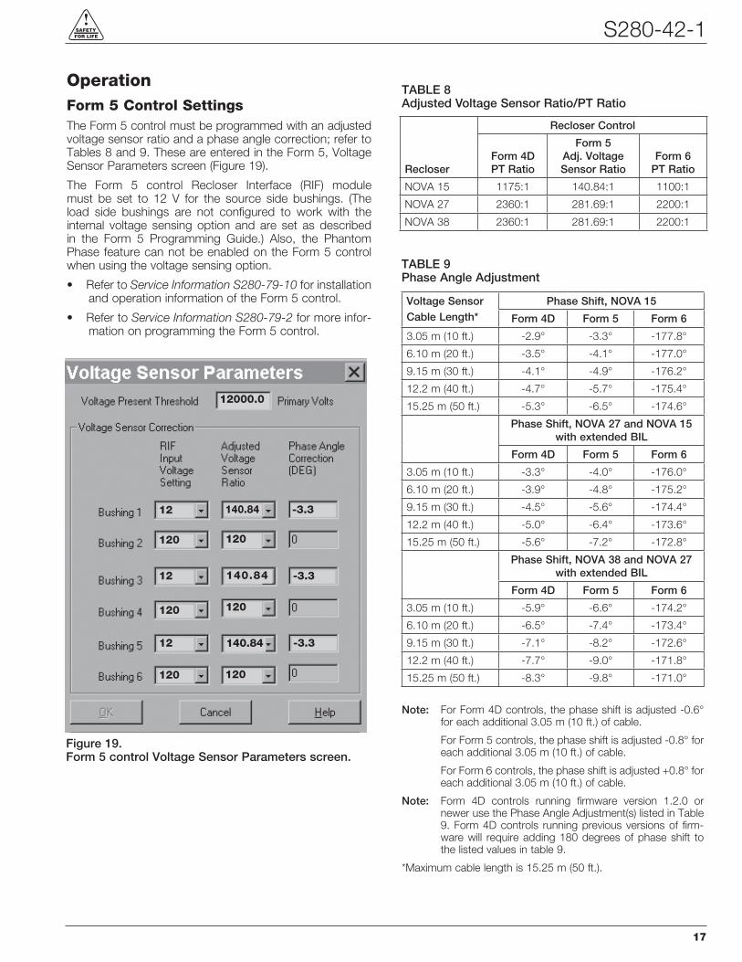
OperationForm 5 Control SettingsThe Form 5 control must be programmed with an adjusted voltage sensor ratio and a phase angle correction; refer to Tables 8 and 9. These are entered in the Form 5, Voltage Sensor Parameters screen (Figure 19).
The Form 5 control Recloser Interface (RIF) module must be set to 12 V for the source side bushings. (The load side bushings are not configured to work with the internal voltage sensing option and are set as described in the Form 5 Programming Guide.) Also, the Phantom Phase feature can not be enabled on the Form 5 control when using the voltage sensing option.
Refer to for installation and operation information of the Form 5 control.
Refer to for more infor-mation on programming the Form 5 control.
S280-42-1
17
SAFETYFOR LIFE
Figure 19.Form 5 control Voltage Sensor Parameters screen.
140.84
140.84
140.84
-3.3
-3.3
-3.3
12
120
12
120
12
120
12000.0
120
120
120
TABLE 8Adjusted Voltage Sensor Ratio/PT Ratio
Recloser
Recloser Control
Form 4D PT Ratio
Form 5 Adj. Voltage Sensor Ratio
Form 6 PT Ratio
NOVA 15 1175:1 140.84:1 1100:1
NOVA 27 2200:1
2200:1
Note:
For Form 5 controls, the phase shift is adjusted -0.8° for
Note: Form 4D controls running firmware version 1.2.0 or newer use the Phase Angle Adjustment(s) listed in Table 9. Form 4D controls running previous versions of firm-ware will require adding 180 degrees of phase shift to the listed values in table 9.
*Maximum cable length is 15.25 m (50 ft.).
TABLE 9Phase Angle Adjustment
Voltage SensorCable Length*
Phase Shift, NOVA 15
Form 4D Form 5 Form 6
-2.9° -177.8°
° -4.1° -177.0°
-4.1° -4.9°
12.2 m (40 ft.) -4.7° -5.7° -175.4°
15.25 m (50 ft.) °
Phase Shift, NOVA 27 and NOVA 15 with extended BIL
Form 4D Form 5 Form 6
-4.0°
° -4.8° -175.2°
-4.5° -174.4°
12.2 m (40 ft.) -5.0°
15.25 m (50 ft.) ° -7.2° -172.8°
Phase Shift, NOVA 38 and NOVA 27 with extended BIL
Form 4D Form 5 Form 6
-5.9° -174.2°
° -7.4°
-7.1° -8.2°
12.2 m (40 ft.) -7.7° -9.0° -171.8°
15.25 m (50 ft.) ° -9.8° -171.0°

Type NOVA Three-Phase, Microprocessor-Controlled Recloser Installation and Operation Instructions
18
Form 4D and Form 6 Control Settings
with a PT ratio and a phase angle adjustment; refer to Tables 8 and 9. These are entered in the System Configuration screen (Figures 20 and 21).
When programming either control, the PT connection must be set for a Wye connection. Also, the Phantom Phase fea-ture must be disabled.
Refer to for more information on programming the Form 4D control.
Refer to for more infor-
Figure 20.Form 4D control System Configuration screen.
Figure 21.Form 6 control System Configuration screen.

Auxiliary SwitchA three-stage auxiliary switch can be provided as an accessory. Each stage has two independent contacts that permit any desired combination of “a” (follow state of recloser contacts) and “b” (opposite recloser contacts)
have a continuous current rating of 10 A. Their interrupting ratings are shown in Table 10.
Terminals
A). Eyebolt, 4/0—1000 mcm (800 A), 2-hole and 4-hole flat- pad terminals, and stud-type terminals are available as an accessory (Figure 22).
The eyebolt, flat-pad, and stud terminals are made of cop-per alloys. Cooper Power Systems recommends terminal connection to copper wires to optimize the electrical con-nection. Aluminum cables may produce aluminum oxide sufficient to compromise the electrical connections.
Anti-oxide coatings for temporary protection of wire-brushed, aluminum cable connections to flat-pad or stud terminals must be maintained at intervals determined by the customer based on load current, climate, and other installation conditions.
Eyebolt terminals are recommended for copper conduc-tors only.
S280-42-1
19
SAFETYFOR LIFE
ACCESSORIES
TABLE 10Auxiliary Switch Interrupting Ratings Non- Non- Inductive Inductive Inductive Inductive ac ac dc dc Volts (A) (A) (A) (A)
24 — — 15.0 20.0
48 — — 7.5 10.0
125 — — 1.5 2.0
250 — — 0.45 0.5

Type NOVA Three-Phase, Microprocessor-Controlled Recloser Installation and Operation Instructions
20
Pole-Mounting HangerA pole-mounting hanger (Figure 22), which bolts directly to the recloser frame, is available for pole-mounting instal-lation.
779(30.75)
Pole
686 mm(27 in)
Pole
637(25.0)
592 Min.(23.25)
MountingHoles
for0.75 Bolts
B
290(11.5)
A
1089(43.0)
OP
EN
Pole
Figure 22.Dimensions of Type NOVA recloser with pole-mounting hanger accessory.
Note: All dimensions are mm (inches). Dimensions shown are approximate.
Dimension B
NOVA 15 791
NOVA 15 847
NOVA 27 847
NOVA 27
NOVA 38
Terminal Options A
Eyebolt,
Eyebolt, 4/0 - 1000 mcm 108 (4.25)
Cable Range (800 A maximum)
Flat Pad, 2-hole 114 (4.5)
Flat Pad, 4-hole 121 (4.75)
(800 A maximum)
Stud Type, 1.125 - 12 threads (800 A maximum)

Arrester-Mounting Brackets
be bolted to the recloser frame and pole-mounting hanger for the addition of inboard and outboard arresters. The arresters are not included with the brackets.
S280-42-1
21
SAFETYFOR LIFE
Pole
468(18.5)
941(37)
468(18.5)
350(13.75)
350(13.75)
396(15.5)
396(15.5)
323 Min.(12.75)
12 (0.50)Mounting Bolt
388(15.5)
388(15.5)
105(4.25)
43(1.75)
240(9.5)
Pole
425(16.75)
406(16)
288(11.25)
Inboard Arrester-Mounting Accessory
Outboard Arrester-Mounting Accessory
Mounting Holesfor 0.75 Bolts
686(27)
Figure 23.Dimensions of Type NOVA recloser with pole-mounting hanger and arrester-mounting bracket accessories.
NOTE: All dimensions are mm (inches). Dimensions shown are approximate.

Substation-Mounting FrameA substation-mounting frame accessory (Figure 24) is available for substation-mounting applications.
Type NOVA Three-Phase, Microprocessor-Controlled Recloser Installation and Operation Instructions
22
B C
NOVA 15 791 508
NOVA 15
NOVA 27
NOVA 27
NOVA 38
Terminal Options A
Eyebolt,
Eyebolt, 4/0 - 1000 mcm 108 (4.25)
Cable Range (800 A maximum)
Flat Pad, 2-hole 114 (4.5)
Flat Pad, 4-hole 121 (4.75)
(800 A maximum)
Stud Type, 1.125 - 12 threads (800 A maximum)
2216(87.25)
adjustable to2826
(111.25) in
76 (3)increments
1060(41.75)
965(38) 457
(18)552(21.75)
19 (0.75)Mounting Hole (4)
B
OP
EN
C
870(34.25)
A
Figure 24.Dimensions of Type NOVA recloser with substation-mounting frame accessory.
Note: All dimensions are mm (inches). Dimensions shown are approximate.

Service RequirementsThe Type NOVA recloser has been designed with a minimum mechanical life of 10,000 operations. The NOVA recloser should be inspected every ten years to check for physical damage and verify proper operation.
Frequency of InspectionBecause these reclosers are applied under widely vary-ing operating and climatic conditions, service intervals are best determined by the user based on actual operating experience. However, solid-insulated, vacuum-interrupting reclosers should be inspected every ten years.
Testing OperationThis recloser is used with Cooper Power Systems micro-processor-based recloser controls. Refer to the control operation manual.
1. Check the data plate ratings. Make sure the rat-ings, settings, and interface options on the recloser data plate (Figure 14 and Table 7) are correct for the planned testing.
2. Test electrical open and close operation. Close and open the recloser contacts using the microprocessor control. Confirm that the contacts have closed and opened by:
A. The OPEN/CLOSE contact position indicator, or
B. By a continuity check between the recloser terminals.
3. Test manual open. Pull the yellow manual open handle (Figure 14) down to open the recloser contacts. Confirm that the contacts have opened by:
A. The OPEN/CLOSE contact position indicator
OR
B. By a continuity check between the recloser terminals.
4. To close the recloser contacts:
A. First, push the yellow manual open handle up.
B. Close the recloser using the microprocessor-based control.
Note: When manual close and open operations are being per-formed from the control front panel, it is recommended
-tion. This recommendation also applies if conducting four operations with fault current applied to the unit.
S280-42-1
23
SAFETYFOR LIFE
SERVICE INFORMATION
WARNING: This equipment is not intended to protect human life. Follow all locally approved pro-
cedures and safety practices when installing or operating this equipment. Failure to comply can result in death, severe personal injury and equipment damage. G102.1

Type NOVA Three-Phase, Microprocessor-Controlled Recloser Installation and Operation Instructions
24
High-Potential Withstand TestingThe following equipment is required for this test:
High-voltage test set – Must be capable of supplying suit-able voltages for determining the dielectric withstand capa-bility of the recloser. Sensitive circuit breakers should be included to prevent damage in the event of a flashover.
Note: Test results for NOVA reclosers equipped with the internal voltage sensing option will be influenced by the source-to-ground connected sensing resistor, especially if DC high-potential testing is performed.
Use the following procedures to perform high-potential withstand tests at 75% of the rated low-frequency with-
voltages and Figure 25 for test connection diagrams.
Test results for NOVA reclosers equipped with the internal voltage sensing option will be influenced by the source-to-ground connected sensing resistor.
Test 1 1. Close the recloser contacts.
2. Ground the recloser.
3.
4. Apply proper test voltage (see Table 11) to terminals 2,
5.seconds.
Test 2 1. Close the recloser contacts.
2. Ground the recloser.
3.
4.
5.seconds.
CAUTION: Radiation. At voltages up to the specified test voltages, the radiation emitted by
the vacuum interrupter is negligible. However, above these voltages, radiation injurious to personnel can be emitted. See
for further information. G109.2
1
3
5
2
4
6
ac
TEST 1
PHASE TO GROUND
1
3
5
2
4
6
ac
TEST 2
PHASE TO PHASE
1
3
5
2
4
6
ac
OPEN CONTACT
1
3
5
2
4
6
ac
OPEN CONTACT
TEST 3
Figure 25.Connection diagrams for high-potential withstand testing.
TABLE 11Type NOVA Recloser Withstand Test Voltage Ratings Information
75% of Rated Low-Frequency Withstand Voltage (1 minute dry) (kV rms) Description AC DC
with internal voltage sensors.
with internal voltage sensors.
with internal voltage sensors.
WARNING: Hazardous voltage. The switchgear (apparatus and control) and high-voltage trans-
former must be in a test cage or similar protected area to prevent accidental contact with the high-voltage parts.
Solidly ground all equipment. Failure to comply can result in death, severe personal injury, and equipment damage. T221.5

Test 3 1. Open the recloser contacts.
2. Ground the recloser.
3.
4.
5.
6.seconds.
7.
8. -onds.
9.seconds.
Withstand Test ResultsThe high-potential withstand tests provide information on the dielectric condition of the recloser and the vacuum integ-rity of the interrupters.
If the recloser passes the closed-contacts tests (Tests 1
is likely to be in the interrupter assembly. Retest each phase individually to determine the failed phase or phases.
If a recloser fails the closed-contacts test, the cause is likely to be a diminished electrical clearance or failed insulation.
authorized service center or your Cooper Power Systems representative.
Note: Test results for NOVA reclosers equipped with the internal voltage sensing option will be influenced by the source-to-ground connected sensing resistor, especially if DC high-potential testing is performed.
Module Flashover ServiceIf a NOVA recloser module was exposed to an external flashover, an inspection process is recommended to assure proper operation of the recloser. Should the NOVA recloser exhibit external flashover attributes (carbon tracking or dis-coloration), the following procedure is recommended:
1. Bypass and remove the recloser from service as described in this manual.
2. Confirm the dielectric strength of the recloser by performing high-potential withstand test. Refer to the High-Potential Withstand Testing section of this manual.
3. Inspect the housing and lifting lugs for damage that may affect electrical and/or mechanical performance. If there is damage to either the housing or lifting lugs they must be replaced or repaired.
4. Inspect module for damage to the terminals. Remove any damaged terminals and replace.
5. Inspect module for damage to the module conductor
module for affixing terminals). If there is damage to the module rods, the module must be replaced. Contact an authorized service center or your Cooper Power Systems representative.
6. Inspect the operating rod for damage. If there is damage to the operating rod, the module must be replaced. Contact an authorized service center or your Cooper Power Systems representative.
7. If no damage is found, clean the module with isopro-pyl alcohol and a scratch-free, nylon scouring pad to remove any carbon deposit.
8. Before returning to service confirm electrical operation by opening and closing the recloser with a control. Confirm the dielectric strength of the recloser by per-forming a high-potential withstand test. Refer to the High-Potential Withstand Testing section of this manual.
TROUBLESHOOTINGIf the Type NOVA recloser does not perform as described in the OPERATION section of this manual, the following information may assist in troubleshooting:
Unit Will Not Close Make sure the yellow manual open handle is com-
pletely up.
level.
-face, verify that auxiliary power is present at recloser.
-face, check the fusing on the DC-to-DC converter board located in the control cabinet.
Unit Will Not Open Electrically
-face, verify that auxiliary power is present at recloser.
-face, check the fusing on the DC-to-DC converter board located in the control cabinet.
S280-42-1
25
SAFETYFOR LIFE

Type NOVA Three-Phase, Microprocessor-Controlled Recloser Installation and Operation Instructions
26
Figure 26.Wiring diagram for NOVA recloser mechanism with auxiliary-powered interface.

S280-42-1
27
SAFETYFOR LIFE
Figure 27.Wiring diagram for NOVA recloser mechanism with control-powered interface.

Type NOVA Three-Phase, Microprocessor-Controlled Recloser Installation and Operation Instructions
©2012 Cooper Industries. All rights reserved.
Cooper Power Systems, Kyle, and NOVA are valuable trade-
marks of Cooper Industries in the U.S. and other countries.
prior written consent of Cooper Industries.ANSI® is a registered trademark of the American National Standards Institute.
Institute of Electrical and Electronics Engineers, Inc., (IEEE).
This product is not endorsed or approved by the IEEE.
IEEE® is a registered trademark of the Institute of Electrical
and Electronics Engineers, Inc., (IEEE). This publication is not
endorsed or approved by the IEEE.
One Cooper | www.cooperpower.com | Online
KA2048-588 Rev: 11
SAFETYFOR LIFE