s215 two-way loudspeaker user's manualthe s215 is a professional two-way loudspeaker system,...
TRANSCRIPT
S215 TWO-WAY LOUDSPEAKER USER’S MANUAL

2
1. Read these instructions.
2. Keep these instructions.
3. Heed all warnings.
4. Follow all instructions.
5. Do not use this apparatus near water.
6. Clean only with dry cloth.
7. Do not block any ventilation openings. Install in accordance with the manufacturer’s instructions.
8. Do not install near any heat sources such as radiators, heat registers, stoves, or other apparatus (including amplifi ers) that produce heat.
9. Only use attachments/accessories specifi ed by the manufacturer.
10. Use only with a cart, stand, tripod, bracket, or table specifi ed by the manufacturer, or sold with the apparatus. When a cart is used, use caution when moving the cart/apparatus combination to avoid injury from tip-over.
11. Refer all servicing to qualifi ed service personnel. Servicing is required when the apparatus has been damaged in any way, such as power-supply cord or plug is damaged, liquid has been spilled or objects have fallen into the apparatus, the apparatus has been exposed to rain or moisture, does not operate normally, or has been dropped.
12. Exposure to extremely high noise levels may cause permanent hearing loss. Individuals vary considerably in susceptibility to noise-induced hearing loss, but nearly everyone will lose some hearing if exposed to suffi ciently intense noise for a period of time. The U.S. Government’s Occupational Safety and Health Administration (OSHA) has specifi ed the permissible noise level exposures shown in the following chart.
According to OSHA, any exposure in excess of these permissible limits could result in some hearing loss. To ensure against potentially danger-ous exposure to high sound pressure levels, it is recommended that all persons exposed to equipment capable of producing high sound pres-sure levels use hearing protectors while the equipment is in operation. Ear plugs or protectors in the ear canals or over the ears must be worn when operating the equipment in order to prevent permanent hearing loss if exposure is in excess of the limits set forth here.
IMPORTANT SAFETY INSTRUCTIONS
WARNING — To reduce the risk of fi re or electric shock, do not expose this
apparatus to rain or moisture.
Duration Per Day Sound Level dBA, Typical In Hours Slow Response Example
8 90 Duo in small club
6 92
4 95 Subway Train
3 97
2 100 Very loud classical music
1.5 102
1 105 Tami screaming at Adrian about deadlines
0.5 110
0.25 or less 115 Loudest parts at a rock concert
PORTABLE CART WARNING
Carts and stands - TheComponent should be usedonly with a cart or standthat is recommended bythe manufacturer.A Component and cartcombination should bemoved with care. Quickstops, excessive force, anduneven surfaces may causethe Component and cartcombination to overturn.

3
CONTENTSIMPORTANT SAFETY INSTRUCTIONS .................................................................................................2
INTRODUCTION ........................................................................................................................................3
HOOKUP DIAGRAMS ...............................................................................................................................4Quick-Start........................................................................................................................................................................... 4
CONNECTIONS ......................................................................................................................................... 6
PLACEMENT ............................................................................................................................................... 6Room Acoustics .................................................................................................................................................................. 6
SERVICE INFORMATION ......................................................................................................................... 8Warranty Service ............................................................................................................................................................... 8Troubleshooting ................................................................................................................................................................ 8Repair .................................................................................................................................................................................... 8
CARE AND MAINTENANCE .................................................................................................................... 9
S215 SPECIFICATIONS .............................................................................................................................. 9
S215 LIMITED WARRANTY .....................................................................................................................11
Don’t forget to visit our website at www.mackie.com for more information about this and oth er Mackie products.
INTRODUCTIONConnecting and setting up the S215 is a breeze. It
accepts a speaker-level signal via either a Neutrik Speakon® connector or female 1/4-inch TS (Tip/Sleeve) connector.
The cabinet is constructed using both 18 mm multi-layer plywood and pressure injected structural resin. A carrying handle is integrated into each side for easy loading and transport.
Thank you for choosing the Mackie S215 sound rein-force ment loudspeakers.
The S215 is a professional two-way loudspeaker system, designed to complement our professional pow-ered mixers and power amplifi ers. They are capable of extremely high sound pressure levels, and designed to give you the best performance of any loudspeaker in its class and price range.
The S215 features a 15-inch high-power low-frequency woofer and a 1.75-inch titanium diaphragm high-output compression driver. The woofer incoporates technology used in large-format touring systems and, with a preci-sion 2.5-inch high-temperature voice coil, is virtually indestructible.
Part No. 0013879 Rev. B 06/05©2004-2005 LOUD Technologies Inc. All Rights Reserved.

4
HOOKUP DIAGRAMSQuick-Start
Make all initial connections with the power switches OFF on all equip-ment. Make sure all master volume, level, or gain controls are all the way down.
1. Connect the line-level outputs from your mixing console (or other signal source) to the inputs of your power amplifi er.
2. Connect the “Speaker Output” from your power amplifi er (or powered mixer) to the INPUT connec-tor on the S215.
S215: WITH A MACKIE POWERED MIXER AND STEREO POWER AMPLIFIER
3. Turn on your mixing console (or other signal source).
4. Turn on the amplifi er. Turn up its volume or gain control(s) as recommended by the manufacturer.
5. Start the signal source, whether it be speaking into a microphone or starting a CD player. Adjust the volume controls on the mixer (or other signal source) for normal operation.
S215: WITH A MIXER AND POWER AMPLIFIER
From LEFTSPEAKER OUT
From RIGHTSPEAKER OUT
From LEFTSPEAKER OUT
From RIGHTSPEAKER OUT
Left and RightMixer Line Outs
EFX
MON
HI12kHz
HI12kHz
MID2.5kHz
MON
MID2.5kHz
MON
HI12kHz
MID2.5kHz
MON
HI12kHz
MID2.5kHz
MON
HI12kHz
MID2.5kHz
MON
HI12kHz
MID2.5kHz
MON
HI12kHz
MID2.5kHz
MON
HI12kHz
MID2.5kHz
LOW80Hz
PAN PAN PAN PAN PAN PAN PAN PAN
VOLUME CH. VOLUME CH. VOLUME CH. VOLUME CH. VOLUME CH. VOLUME CH. VOLUME CH. VOLUME CH.
1
EFX
LOW80Hz
2
2
EFX
LOW80Hz
3
3
EFX
LOW80Hz
4
4
EFX
LOW80Hz
5
5
EFX
LOW80Hz
6
6
EFX
LOW80Hz
7 8
7
EFX
LOW80Hz
8
EFX BYPASS
EFX DRIVELEVEL
120
NORMAL
INPUT LEVEL
SET
INPUT LEVEL
SET
INPUT LEVEL
SET
INPUT LEVEL
SET
INPUT LEVEL
SET
INPUT LEVEL
SET
INPUT LEVEL
SET
INPUT LEVEL
SET
EFXCLIP
PARAMETERS
100 100
REVERBSDELAYS
CHORUSFLANGE
DAMPING
DEPTH
PHASER
TIME
RATE
NORMAL NORMAL
CUSTOM 32-BIT PRECISIONDIGITAL STEREO EFFECTS PROCESSING
EFX WIDE
MAIN-STEREO/MONO EQUALIZER
30
CLIP
5
5
0
10
15
20
EFX FOOTSWITCH
RIGHT RETURNLEFT RETURN
SEND
L MIXER OUT R MIXER OUT COMPRESSOR
L POWERAMP IN
R POWERAMP IN
EFFECTS(OVERRIDES INTERNAL EFX) MONITORMAINS
TAPE IN
TAPE OUT
LEVEL
MIC 1 MIC 2 MIC 3 MIC 4 MIC 5 MIC 6
INSERT INSERT INSERT INSERT INSERT
LINELINELINELINELINELINE
INSERT
+15
U
OO
1K50025063 125 16K
LEVEL
2K 4K 8K
MAIN MASTER
EFX TOMAIN
U
OO +10
MASTER OUTPUT SECTION
LINE
U
+12dBOO
L R
RL
POWER
OUT
MONITOR EQUALIZER
15-
15+
5
10
0
5
10
-15
+15
5
10
0
5
10
15-
15+
5
10
0
5
10
-15
+15
5
10
0
5
10
1K50025063 125 16K2K 4K 8K
MONITORMASTER
EFX TOMON
U
OO +10
U
+12dBOO
75Hz RUMBLEREDUCTION
RIGHT RIGHT
MIC 7 MIC 8
75Hz RUMBLEREDUCTION
PHANTOMPOWER CH 1-8
BREAK(MUTES CH 1-6)
408SPOWER AMP ROUTING
SM. ROOMMD. PLATELG. PLATE
LG. HALL
GATEDREVERSE
CATHEDRAL
MD. HALL
SPRINGPHASER
DELAY 4CHORUS
DELAY 3
DELAY 1
FLANGE
DELAY 2
INOUT
STEREO MAINSLEFT = MAINRIGHT = MONITOR
2 X 250W STEREO
LEVEL
30
CLIP
5
5
0
10
15
20
L R
LEFT/MONO LEFT/MONO
STEREOMIC/LINEHI-Z
STEREOMIC/LINEHI-Z
U
OO+10
U
+15-15
U
+15-15
U
+12-12
1
U
+20dBOO
HILOW
NORMAL
U
OO+15U
OO+10
U
+15-15
U
+15-15
U
+12-12
U
+20dBOO
HILOW
NORMAL
U
OO+15U
OO+10
U
+15-15
U
+15-15
U
+12-12
U
+20dBOO
HILOW
NORMAL
U
OO+15U
OO+10
U
+15-15
U
+15-15
U
+12-12
U
+20dBOO
HILOW
NORMAL
U
OO+15U
OO+10
U
+15-15
U
+15-15
U
+12-12
U
+20dBOO
HILOW
NORMAL
U
OO+15U
OO+10
U
+15-15
U
+15-15
U
+12-12
U
+20dBOO
HILOW
NORMAL
U
OO+15U
OO+10
U
+15-15
U
+15-15
U
+12-12
U
+20dBOO
HILOW
NORMAL
U
OO+15U
OO+10
U
+15-15
U
+15-15
U
+12-12
U
+20dBOO
HILOW
NORMAL
RL RL RL RL RL RL RL RL
U
OO+15
S215 S215
S215 S215
Stereo Power Amplifier
Stereo Powered Mixer
SERIAL NUMBER MANUFACTURING DATESERIAL NUMBER MANUFACTURING DATE
S215 DESIGNED BY MACKOIDS IN WHITINSVILLE, MA & WOODINVILLE, WA,USA
"MACKIE" AND THE "RUNNING MAN" FIGURE ARE REGISTERED TRADEMARKS OF LOUD TECHNOLOGIES INC. • COPYRIGHT ©2004
NO
MIN
AL
IMPE
DA
NC
E: 8
OH
MS
POW
ER H
AN
DLI
NG
: CO
NT
/ 35
0W •
PEA
K/
1400
W
PIN
1 +
+
PIN
1 -
-
T
IP
+
S
LEEV
E
-
1/
4"N
L4
Mixer orPreamplifier
RightLine-levelOutput
LeftLine-level
Output
StereoPower Amplifier
1202-VLZPRO
S215 S215
5
SERIAL NUMBER MANUFACTURING DATESERIAL NUMBER MANUFACTURING DATE
S215 DESIGNED BY MACKOIDS IN WHITINSVILLE, MA & WOODINVILLE, WA,USA
"MACKIE" AND THE "RUNNING MAN" FIGURE ARE REGISTERED TRADEMARKS OF LOUD TECHNOLOGIES INC. • COPYRIGHT ©2004
NO
MIN
AL
IMPE
DA
NC
E: 8
OH
MS
POW
ER H
AN
DLI
NG
: CO
NT
/ 35
0W •
PEA
K/
1400
W
PIN
1 +
+
PIN
1 -
-
T
IP
+
S
LEEV
E
-
1/
4"N
L4
S215
Mixer orPreamplifier
RightLine-levelOutput
LeftLine-level
Output
StereoPower Amplifier
1202-VLZPRO
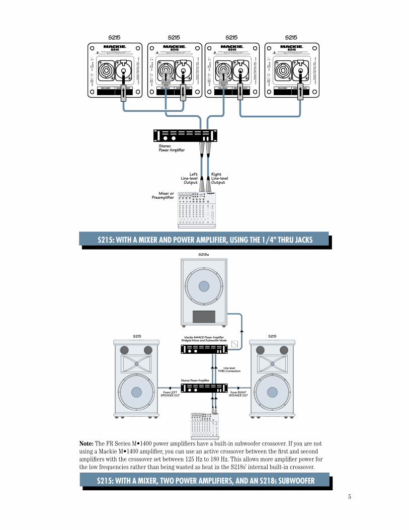
S215: WITH A MIXER AND POWER AMPLIFIER, USING THE 1/4" THRU JACKS
S215: WITH A MIXER, TWO POWER AMPLIFIERS, AND AN S218S SUBWOOFER
Note: The FR Series M•1400 power amplifi ers have a built-in subwoofer crossover. If you are not using a Mackie M•1400 amplifi er, you can use an active crossover between the fi rst and second amplifi ers with the crossover set between 125 Hz to 180 Hz. This allows more amplifi er power for the low frequencies rather than being wasted as heat in the S218s’ internal built-in crossover.
S215 S215
S218s
1202-VLZPRO
Stereo Power Amplifier
Mackie M•1400 Power AmplifierBridged Mono and Subwoofer Mode
From LEFTSPEAKER OUT
From RIGHTSPEAKER OUT
Line-levelTHRU Connection

6
CONNECTIONSThe S215 has two connectors labeled IN/OUT. One is a
Neutrik Speakon™ connector and the other is a female 1/4" TS connector. These connectors are wired in paral-lel, and can be used either as an input from a power amplifi er, or as a “thru” connection for connecting the input signal to another speaker’s input.
NEVER connect more than one output from a power amplifi er to the S215 inputs.
Keep in mind, when connecting two or more speakers in parallel using the “thru” connections, that you want to be sure not to go below the minimum impedance requirements for your power amplifi er.
The S215 has a nominal impedance of 8 ohms. Two S215s in parallel equals 4 ohms. Three S215s in parallel equals 2.7 ohms. Four S215s in parallel equals 2 ohms.
Use high-quality speaker cable as recommended by the power amplifi er manufacturer.
DO NOT use coaxial shielded cable like a guitar cord to make speaker connections. They are not designed to handle the high currents required to drive a loudspeaker.
The Speakon connector is wired as follows:Pin 1+ = Signal (“+” or hot)Pin 1– = Ground (“–” or cold)
PLACEMENTThe S215 speaker is designed to sit on the fl oor or
stage. It can be pole-mounted via the built-in socket on the bottom of the cabinet. Be sure the pole is capable of supporting the weight of the S215.
WARNING: The cabinet has no rig-ging points and is not suitable for rigging. NEVER attempt to suspend the S215 by its handles.
You can create a horizontal array by placing the cabi-nets side-by-side. However, you should have a good un-derstanding of the relationship between the splay angle (the angle between the facing sides of the cabinets), the on-axis power, and frequency cancellation effects between cabinets.
When two cabinets are placed side-by-side, the actual splay angle is 20º (determined by a 10º angle on each cabinet side). As the splay angle increases toward the angle of horizontal coverage (75º for the S215), the on-axis power decreases, but the frequency response be comes smoother as the comb-fi ltering effects (caused by the interaction in the area of double-coverage) decrease.
As with any powered components, protect them from moisture. If you are setting them up outdoors, make sure they are under cov er if you expect rain.
Room Acoustics
The S215 loudspeakers are designed to sound as neu-tral as possible; that is, to reproduce the input signal as accurately as possible.
Room acoustics play a crucial role in the overall per-formance of a sound system. Here are some additional placement tips to help overcome some typical room problems that might arise:
• Avoid placing loudspeakers in the corners of a room. This increases the low frequency output and can cause the sound to be muddy and indistinct.
• Avoid placing loudspeakers against a wall. This, too, increases the low frequency output, though not as much as corner placement. However, if you do need to reinforce the low frequencies, this is a good way to do it.
COLD
HOT1+
1+
1–
1–
2–2+
SLEEVE
TIP
TIPSLEEVE
TIP
SLEEVE
Speakon Connectors
The 1/4" TS jack is wired as follows:Tip = Signal (“+” or hot)Sleeve = Ground (“–” or cold)
1/4" TS Connectors

7
• Avoid placing the speakers directly on a hollow stage fl oor. A hollow stage can resonate at certain frequencies, causing peaks and dips in the fre-quency response of the room. It’s better to place the loudspeakers on a sturdy table or stand designed to handle the weight of the S215s.
• Position the loudspeakers so the high-frequency drivers are 2 to 4 feet above ear level for the audi-ence (make allowances for a standing/dancing in the aisles audience). High frequencies are highly directional and tend to be absorbed much easier than lower frequencies. By providing direct line-of-sight from the loudspeakers to the audience, you increase the overall brightness and intelligibility of the sound system.
• Highly reverberant rooms, like many gymnasiums and auditoriums, are a nightmare for sound system intelligibility. Multiple refl ections off the hard walls, ceiling, and fl oor play havoc with the sound. Depend-ing on the situation, you may be able to take some steps to minimize the refl ections, such as putting carpeting on the fl oors, closing draperies to cover large glass windows, or hanging tapestries or other materials on the walls to absorb some of the sound.
However, in most cases, these remedies are not possible or practical. So what do you do? Making the sound system louder generally doesn’t work because the refl ections become louder, too. The best approach is to provide as much direct sound coverage to the audience as possible. The farther away you are from the speaker, the more prominent will be the refl ected sound.
Use more speakers strategically placed so they are closer to the back of the audience. If the distance between the front and back speakers is more than about 100 feet, you should use a delay processor to time-align the sound. (Since sound travels about 1 foot per millisecond, it takes about 1/10 of a second to travel 100 feet.)

8
Repair
Service for Mackie products is available at a factory-authorized service center. Service for Mackie products outside the United States can be obtained through local dealers or distributors.
If your S215 needs ser vice, please fol low these in- struc tions:
1. Review the preceding trou ble shoot ing sug ges tions. Please.
2. Call Tech Support at 1-800-898-3211, 7 am to 5 pm PST, to explain the prob lem in detail. They will ask you all sorts of impertinent questions in the hope of sorting out the problem. If it appears that the S215 needs repair, you will be given a Service Request Number. Have your loudspeaker’s serial number ready. You must have a Service Request Num ber be-fore you can obtain service at a factory-au tho rized service center.
3. Keep this user’s manual and the de tach able line-cord. We don’t need them to repair the loud speak er.
4. Pack the loudspeaker in its original pack ag ing, including protective wrap, endcaps, and box. This is VERY IMPORTANT. When you call for the Service Request Number, please let Tech Support know if you need new pack ag ing. Mackie is not re spon si ble for any damage that occurs due to non-factory pack ag ing.
5. Include a legible note stating your name, shipping address (no P.O. boxes), daytime phone number, Service Request Number, and a detailed de scrip tion of the prob lem, in clud ing how we can duplicate it.
6. Write the Service Request Number in BIG PRINT on top of the box. Product shipped with-out the Service Request Number will be refused.
7. Tech Support will tell you where to ship the loud-speaker for repair. We suggest insurance for all forms of cart age.
8. We’ll try to fi x the loudspeaker with in fi ve business days. Once it is repaired, we’ll ship it back the same way in which it was received. This para graph does not nec es sar i ly apply to non-war ran ty service.
Note: You must have a sales receipt from an Autho-rized Mackie Dealer to qualify for a warranty repair.
SERVICE INFORMATION
Warranty Service
Details concerning warranty service are spelled out on page 11 of this manual.
If you think your loudspeaker has a prob lem, please do everything you can to con fi rm it before calling for service, in clud ing reading through the following Trou ble shoot ing sec tion. Doing so might save you from being de prived of your Mack ie loudspeaker.
Of all Mackie prod ucts returned for ser vice (which is hardly any at all), many are coded “CND” — Could Not Duplicate— which usually means the problem lay some- where else in the sys tem. The following trou ble shoot ing tips may sound obvious, but here are some things you can check:
Troubleshooting
No sound• Are the level controls on the mixer or amplifi er
turned all the way down? Follow the procedures in the “Quick-Start” section on page 4 to verify that all the vol ume controls in the system are properly ad just ed.
• Is the signal source working (and making union scale)? Make sure the con nect ing cables are in good repair and se cure ly connected at both ends.
• Make sure the mixer does not have a Mute on or a Processor loop en gaged. If you fi nd something like this, make sure the volume/gain is turned down before disengaging the offending switch.
Poor bass performance• Check the polarity of the connections between the
mixer and the loud speak ers. You may have your positive and negative connections re versed at one end of one cable, causing one loud speak er to be out-of-phase.
Poor sound• Is it loud and distorted? Make sure that you’re not
overdriving a stage in the signal chain. Verify that all level controls are set properly.
• Is the input connector plugged com plete ly into the jack? Make sure all con nec tions are secure. It’s a good idea to periodically clean all electrical con- nec tions with a non-lu bri cat ing electrical contact cleaner.
9
S215 SPECIFICATIONSAcoustic Performance
Frequency Range (–10 dB)
55 Hz–20 kHz Frequency Response (–3 dB)
80 Hz–18 kHz Horizonal Coverage Angle (–6 dB)
90º averaged 2 kHz to 10 kHz Vertical Coverage Angle (–6 dB)
40º averaged 2 kHz to 10 kHz Directivity Factor; DI (Q)
12.1 (16.4) averaged 2k Hz to 10 kHz Sensitivity (1W/1m) 100 dB SPL Max SPL long-term 127 dB @ 1m Max SPL peak 130 dB @ 1m Crossover Point 1300 Hz
Input/Output
Input/Output Type Neutrik Speakon™ and female 1/4-in. TS jack Input Impedance 8 ohms Recommended Amplifi er Power
350 watts rms continuous 1400 watts peak
High-Frequency Section
Voice Coil Diameter 1.75 in/44 mm Horn Exit Diameter 1.0 in/25 mm Phase Plug Optimized geometry Diaphragm Material Titanium Magnet Material Ferrite
Low-Frequency Section
Woofer Diameter 15.0 in/381 mm Voice Coil Diameter 2.5 in/63 mm Diaphragm Material Epoxy-reinforced cellulose Magnet Material Ferrite
Safety Features
In put Protection Dynamic protection for compression driver
Construction Features
Basic Design Trapezoidal, 10º side angles Material 18 mm multi-layered plywood, resin end caps Finish Wear-resistant textured black PVC vinyl Handles One on each side, one top, one bottom Grille Perforated metal with weather- resistant coating
Physical Properties
Height 32.0 in/81.3 cm Front Width 19.1 in/48.5 cm Rear Width 13.9 in/35.3 cm Depth 18.1 in/46.0 cm Weight 67 lb/30.4 kg Mounting Methods Floor mount only. The S215 cabinet has no rigging points and is not suitable for fl ying. Never attempt to suspend the cabinet by its handles. The S215 is pole- mountable via the built-in socket on the bottom of the cabinet. Be sure the pole is capable of supporting the weight of the S215 cabinet.
Disclaimer
Since we are always striving to make our products better by in- cor po rat ing new and im proved ma te ri als, com po nents, and man u fac -tur ing methods, we re serve the right to change these spec i fi ca tions at any time with out no tice.
“Mackie” and the “Running Man” fi gure are reg is tered trade marks of LOUD Technologies Inc.
All other brand names men tioned are trade marks or registered trademarks of their respective hold ers, and are hereby ac knowl edged.
©2004-2005 LOUD Technologies Inc.All Rights Reserved.
CARE AND MAINTENANCEYour Mackie loudspeakers will pro vide many years of
reliable ser vice if you fol low these guide lines:
Avoid exposing the loudspeakers to mois ture. If they are set up out doors, be sure they are under cover if you expect rain.
Need Help?
You can reach a technical support representative Monday through Friday
from 7 AM to 5 PM PST at:
1-800-898-3211
After hours, visit www.mackie.com and click Support, or email us at: [email protected]
• Avoid exposure to extreme cold (be low freezing tem per a tures). If you must operate the loud- speak ers in a cold en vi ron ment, warm up the voice coils slowly by sending a low-level sig nal through them for about 15 minutes prior to high-power op er a tion.
• Use a slighty damp cloth with a mild soap so lu tion to clean the cabinets. Only do this when the power is turned off. Avoid getting mois ture into any of the open ings of the cab i net, par tic u lar ly where the driv-ers are located.

10
S215 Beamwidth vs. Frequency S215 Directivity vs. Frequency
S215 Dimensions
S215 Frequency Response On-Axis
PRECISION PASSIVE
PIN 1 INPIN 2 N/C
SERIAL NUMBER MANUFACTURING DATE
S215
IN / OUT IN / OUT
DESIGNED BY MACKOIDS IN WHITINSVILLE, MA & WOODINVILLE, WA,USAMANUFACTURED IN CHINA • "MACKIE" AND THE "RUNNING MAN" FIGURE
ARE REGISTERED TRADEMARK OF LOUD TECHNOLOGIES INC. • COPYRIGHT ©2004
32.0 in/81.3 cm
13.9 in/35.3 cm
18.1 in/46.0 cm
19.1 in/48.5 cm
19.1 in/48.5 cm
Frequency (Hz)20 100 1000 10000 20000
110
100
90
80
70
1/3
Oct
ave
Res
pons
e
dB S
PL
@ 2
.83
V
S215 Frequency Response On-Axis
Horizontal / Vertical
Frequency (Hz)20 100 1000 10000 20000
Bea
mw
idth
Deg
rees
360
300
240
180
120
60
0
Frequency (Hz)20 100 1000 10000 20000
100
10
1
Dire
ctiv
ity F
acto
r (Q
)
Dire
ctiv
ity I
ndex
(D
I),
dB
20
10
0

11
A. LOUD Technologies Inc. warrants all materials, workmanship and proper operation of this product for a period of two years from the original date of purchase. If any defects are found in the materials or workmanship or if the product fails to function properly during the applicable warranty period, LOUD Technologies, at its option, will repair or replace the product. This warranty applies only to equipment sold and delivered within the U.S. by LOUD Technologies Inc. or its authorized dealers.B. Failure to register online or return the product registration card will not void the two-year warranty.
C. Service and repairs of Mackie products are to be performed only at a factory-authorized facility (see D below). Unauthorized service, repairs, or modifi cation will void this warranty. To obtain repairs under warranty, you must have a copy of your sales receipt from the authorized Mackie dealer where you purchased the product. It is necessary to establish purchase date and determine whether your Mackie product is within the warranty period.
D. To obtain factory-authorized service:
1. Call Mackie Technical Support at 800/898-3211, 7 AM to 5 PM Monday through Friday (Pacifi c Time) to get a Service Request Number. Products returned without a Service Request Number will be refused.
2. Pack the product in its original shipping carton. Also include a note explaining exactly how to duplicate the problem, a copy of the sales receipt with price and date showing, and your return street address (no P.O. boxes or route numbers, please!). If we cannot duplicate the problem or establish the starting date of your Limited Warranty, we may, at our option, charge for service time.
3. Ship the product in its original shipping carton, freight prepaid to the authorized service center. The address of your closest authorized service center will be given to you by Technical Support.
IMPORTANT: Make sure that the Service Request Number is plainly written on the shipping carton.
E. LOUD Technologies reserves the right to inspect any products that may be the subject of any warranty claims before repair or replacement is carried out. LOUD Technologies may, at our option, require proof of the original date of purchase in the form of a dated copy of the original dealer’s invoice or sales receipt. Final determination of warranty coverage lies solely with LOUD Technologies.
F. Any products returned to one of the LOUD Technologies factory-authorized service centers and deemed eligible for repair or replacement under the terms of this warranty will
be repaired or replaced within thirty days of receipt. LOUD Technologies and its authorized service centers may use refurbished parts for repair or replacement of any product. Products returned to LOUD Technologies that do not meet the terms of this Warranty will be not be repaired unless payment is received for labor, materials, return freight, and insurance. Products repaired under warranty will be returned freight prepaid by LOUD Technologies to any location within the boundaries of the USA.
G. LOUD Technologies warrants all repairs performed for 90 days or for the remainder of the warranty period. This warranty does not extend to damage resulting from improper installation, misuse, neglect or abuse, or to exterior appearance. This warranty is recognized only if the inspection seals and serial number on the unit have not been defaced or removed.
H. LOUD Technologies assumes no responsibility for the quality or timeliness of repairs performed by an authorized service center.
I. This warranty is extended to the original purchaser and to anyone who may subsequently purchase this product within the applicable warranty period. A copy of the original sales receipt is required to obtain warranty repairs.
J. This is your sole warranty. LOUD Technologies does not authorize any third party, including any dealer or sales representative, to assume any liability on behalf of LOUD Technologies or to make any warranty for LOUD Technologies Inc.
K. THE WARRANTY GIVEN ON THIS PAGE IS THE SOLE WARRANTY GIVEN BY LOUD TECHNOLOGIES INC. AND IS IN LIEU OF ALL OTHER WARRANTIES, EXPRESS AND IMPLIED, INCLUDING THE WARRANTIES OF MERCHANTABILITY AND FITNESS FOR A PARTICULAR PURPOSE. THE WARRANTY GIVEN ON THIS PAGE SHALL BE STRICTLY LIMITED IN DURATION TO TWO YEARS FROM THE DATE OF ORIGINAL PURCHASE FROM AN AUTHORIZED MACKIE DEALER. UPON EXPIRATION OF THE APPLICABLE WARRANTY PERIOD, LOUD TECHNOLOGIES INC. SHALL HAVE NO FURTHER WARRANTY OBLIGATION OF ANY KIND. LOUD TECHNOLOGIES INC. SHALL NOT BE LIABLE FOR ANY INCIDENTAL, SPECIAL, OR CONSEQUENTIAL DAMAGES THAT MAY RESULT FROM ANY DEFECT IN THE MACKIE PRODUCT OR ANY WARRANTY CLAIM. Some states do not allow exclusion or limitation of incidental, special, or consequential damages or a limitation on how long warranties last, so some of the above limitations and exclusions may not apply to you. This warranty provides specifi c legal rights and you may have other rights which vary from state to state.
Please keep your sales re ceipt in a safe place.
S215 LIMITED WARRANTY

16220 Wood-Red Road NE • Woodinville, WA 98072 • USA
US and Canada: 800.898.3211
Europe, Asia, Central and South America: 425.487.4333
Middle East and Africa: 31.20.654.4000
Fax: 425.487.4337 • www.mackie.com
E-mail: [email protected]