s15062 ductile iron pipe
TRANSCRIPT
SECTION 15062
DUCTILE IRON PIPE PART 1 – GENERAL 1.1. DESCRIPTION
A. This Section covers ductile iron pipe fittings, flanges, specials, and other accessories. 1.2. SUBMITTALS
A. Certification. 1. Submit manufacturer’s certification that products meet the referenced standards.
B. Shop Drawings.
1. Submit manufacturer’s specifications and details for all ductile iron pipe and accessories.
2. Submit complete layout drawings and details of connections for all piping installed within the limits of structures and for all exterior plant piping.
1.3. PRODUCT DELIVERY, STORAGE, AND HANDLING
A. Handling. 1. Use slings, pipe tongs, or skids. 2. Do not drop pipe or fittings including dropping on old automobile tires or other
cushions. 3. Do not skid or roll pipe into pipe already on the ground. 4. Do not damage coating or lining. 5. Do not use hooks, chains, or bare cables.
B. Storage.
1. Maintain lubricant in a sanitary condition during storage. 2. Store rubber gaskets in a cool, dark location away from grease, oil, ozone
producing electric motors, and the direct rays of the sun. 3. Do not exceed maximum stacking heights listed in AWWA C600, Tables 1 and
2. 1.4. ALTERNATIVES
A. Grooved-end couplings may not be used in lieu of flanged joints indicated on the Drawings, unless specifically approved in writing by the Engineer. Where flanged coupling adaptors are indicated, Mega-Flange restrained flange coupling adapters as manufactured by EBAA Iron Sales, Inc. shall be used.
06-048.10 15062-1 12/11/06

PART 2 – PRODUCTS 2.1. PIPE
A. Pipe. 1. Standard: ANSI 21.51 (AWWA C151). 2. Pressure class:
a. Four inches (4”) through twelve inches (12”): three hundred fifty pounds per square inch (350 psi).
b. Fourteen inches (14”) through twenty inches (20”): two hundred fifty pounds per square inch (250 psi).
c. Twenty-four inches (24”): two hundred pounds per square inch (200 psi.).
B. Flanged Pipe.
1. Standard: ANSI 21.51 (AWWA C115), flat faced. 2.2. FITTINGS
A. Flanges, Mechanical Joint, Push-on. 1. Standard: ANSI A21.10 (AWWA C110). 2. Dimensions: Shorter laying lengths will be acceptable except where longer
lengths are indicated on the Drawings. 3. Material: Ductile Iron. 4. Pressure Rating.
a. Twelve inches (12”) and smaller: Two hundred fifty pounds per square inch (250 psi).
b. Over twelve inches (12”): One hundred fifty pounds per square inch (150 psi).
5. Gaskets: Synthetic Rubber, except EPDM for air service. B. Threaded.
1. Standard: ANSI B16.4, ANSI B16.14. 2. Pressure Rating: One hundred seventy-five (175) psi.
2.3. JOINTS
A. Mechanical and Push-on. 1. Standard: ANSI A21.11 (AWWA C111). 2. Gaskets: Synthetic Rubber. 3. Lubricant: Furnished by pipe manufacturer. 4. Provide joint retainer gland on all exposed mechanical joints unless tie rods are
indicated on the Drawings. B. Flanged.
1. Standard: ANSI A21.51. 2. Flanges: ANSI B16.1. 3. Drilling: One hundred twenty-five pounds (125 lbs.), unless otherwise indicated. 4. Gaskets: Synthetic Rubber, except EPDM for air service. 5. Bolts and Nuts: ASTM A 307, Grade B, galvanized or plated.
06-048.10 15062-2 12/11/06
C. Restrained Joints (where shown on the Drawings).
1. Mechanical Joints: Mega-lug Retainer Gland, EBAA Iron. 2. Push on-joints: American Pipe Co. Fast-Grip gasket, U.S. Pipe Field-LOK, or
Griffin Pipe Snap-Lok. for four inch (4”) to twelve inch (12”) pipe. 3. Push on-joints: American Pipe Co. Flex-Ring Joint, U.S. Pipe TR Flex, or
Griffin Pipe Snap-Lok for fourteen inch (14”) to twenty-four inch (24”) pipe, or equal.
4. All pipe beneath structures shall be restrained joint or mechanical joint with Mega-lugs.
5. Pipe manufacturer shall be responsible for design and layout of restrained joint system.
6. Field Cut Restrained Joints. a. Install where field cuts are necessary on restrained joint pipe. b. All materials shall have the same pressure rating as the pipe. c. Allowable Manufacturers.
1) U.S. Pipe, TR Flex Gripper Rings. 2) American, Field Flex Ring. 3) Griffin, Snap Lok FC.
2.4. COUPLINGS
A. Mechanical Couplings. 1. Standard: ANSI/AWWA C 219. 2. Type: Mechanical compression sleeve. 3. Material.
a. Sleeve: 1) Carbon Steel. 2) Omit pipe stop unless otherwise indicated on the Drawings.
b. End Ring: Steel. c. Bolts:
1) High strength steel. 2) Galvanized or plated.
d. Coating: 1) Epoxy coated, interior and exterior ferrous surfaces. 2) ANSI/AWWA C 210.
e. Gaskets: ASTM D 2000. 1) Water and wastewater: Synthetic rubber. 2) Air: EPDM.
f. Accepted Manufacturer. 1) Dresser Style 38. 2) Smith-Blair Type 411. 3) Or equal.
B. Flanged Coupling Adapters.
1. Material. a. Body.
1) Ductile iron. 2) Standard: ASTM A536. 3) Flange coupling adapters with pipe penetrating anchor or locking
06-048.10 15062-3 12/11/06
pins will not be allowed. b. Flange:
1) Compatible with ANSI/AWWA C115/A21.15. c. Gaskets:
1) ASTM D 2000. 2) Water and wastewater: Synthetic rubber. 3) Air: EPDM.
d. Coating: 1) Manufacturer’s standard. 2) ANSI/AWWA C 210.
e. Bolts: 1) High strength steel. 2) Galvanized or plated.
2. Accepted Manufacturer. a. EBAA Iron Sales, Inc.: Series 2100, Mega-Flange. b. Or equal.
C. Transition Couplings.
1. Standard: a. ANSI/AWWA C 219.
2. Material. a. Sleeve: Carbon steel. b. End Ring: Ductile iron. c. Bolts:
1) High strength steel. 2) Galvanized or plated.
a. Coating: 1) Epoxy coated, interior and exterior ferrous surfaces. 2) ANSI/AWWA C 210.
b. Gaskets: ASTM D2000. 1) Water and wastewater: Synthetic rubber. 2) Air: EPDM.
3. Accepted Manufacturer. a. Dresser Style 162. b. Ford FC23 or FC24. c. Smith-Blair Type 413. d. Or equal.
D. Wall Castings.
1. Material: Steel. 2. Accepted Manufacturer:
a. Thunderline Corp., Link-Seal Model WS b. Or equal.
2.5. PIPE LINING
A. Cement Mortar. (Underground 48” and 36” raw water transmission lines, 36” fittings and reducers – filter influent piping) 1. Standard: ANSI A21.4. 2. Thickness: Standard.
06-048.10 15062-4 12/11/06

B. Liquid Epoxy. (Interior and Exterior piping and fittings, 24” and smaller.
1. Reference Standard: AWWA C210 except no coal tar products shall be blended in the liquid epoxy.
2. Surface Preparation: SSPC-SP10, Near White Blast Cleaning. 3. ANSI/NSF Std. 61 certified polyamidoamine epoxy, 16 mils DFT using a
minimum of two coat application. 4. Manufacturer: Pota-Pox by Tnemec, Bar-Rust by DeVoe, or approved equal.
2.6. PIPE COATINGS
A. Underground or Submerged Locations. 1. Type: Bituminous. 2. Thickness: Approximately one (1) mil. 3. Underground: Polyethylene encasement. 4. Submerged: Painted per exposed locations.
B. Exposed Locations.
1. Pipe. a. Primer; Tnemec “77 Chem-Prime.” b. Mobil “13-R-50 Chromox Q.D.” c. FBE – AWWA C153 – 8 mills. d. Or equal.
2. Flange faces. a. Rust-Oleum “R-9.” b. Houghton “Rust Veto 344.” c. Or equal.
3. Finish coats: Refer to Section 09900 - Painting. 2.7. ACCESSORIES
A. Polyethylene Encasement. 1. Standard: ANSI 21.5 (AWWA C105). 2. Method: A.
PART 3 – EXECUTION 3.1. INSPECTION
A. Examine pipe and fittings and do not use individual sections containing the following. 1. Cracks. 2. Flaws. 3. Broken, cracked, or loose lining. 4. Other defects.
B. Mark defective pipe and remove from the site. C. Refer to Section 15076 – Miscellaneous Piping and Accessories and Section 15090 –
Supports and Anchors for additional installation requirements.
06-048.10 15062-5 12/11/06
D. Cutting the pipe. 1. Cut pipe smooth, straight, and at right angles to the pipe axis. 2. Do not damage the pipe or cement lining. 3. Use a saw, abrasive wheel, or oxyacetylene torch for ductile iron pipe. 4. Do not use an oxyacetylene torch for cutting holes for saddles. 5. Grind cut ends and rough edges smooth. 6. Bevel the cut end for push-on joints.
E. Polyethylene Encasement.
1. Install polyethylene encasement on ductile iron pipe at all underground locations. 2. Cut polyethylene tube to a length approximately two feet (2’) longer than that of
the pipe section. 3. Slip the tube around the pipe, centering it to provide a one foot (1’) overlap on
each adjacent pipe section, and bunching it accordion fashion lengthwise until it clears the pipe ends.
4. A shallow bell hole must be made at joints to facilitate installation of the polyethylene tube.
5. After assembling the pipe joint, make the overlap of the polyethylene tube. 6. Pull the bunched polyethylene from the preceding length of pipe, slip it over the
end of the new length of pipe, and secure in place. 7. Then, slip the end of the polyethylene from the new pipe section over the end of
the first wrap until it overlaps the joint at the end of the preceding length of pipe. 8. Secure the overlap in place. 9. Take up the slack width to make a snug, but not tight, fit along the barrel of the
pipe, securing the fold at the top of the pipe. 3.3. JOINT INSTALLATION
A. General. 1. Use push-on or mechanical joints in underground locations, unless indicated
otherwise on the Drawings. 2. Use flanged joints at other locations unless indicted otherwise on the Drawings. 3. All joints shall be watertight and free from leaks. 4. Repair each leak discovered within one (1) year after final acceptance. 5. Block, anchor, or harness all mechanical couplings and push-on or mechanical
joints. 6. Do not deflect joints beyond the maximum values specified in AWWA C600.
B. Push-On Joints.
1. Clean the inside of the bell and the outside of the spigot to remove dirt, oil, excess coating, and other foreign matter.
2. Insert the gasket. 3. Apply a thin film of lubricant to either the inside surface of the gasket, the spigot
end of the pipe, or both. 4. Do not permit the joint surfaces to come in contact with the ground. 5. Assure that pipe is marked with a depth mark before assembly to assure the
spigot end is inserted the full depth of the joint. 6. Complete the joint making certain the spigot is inserted to the depth mark.
C. Mechanical Joints.
06-048.10 15062-6 12/11/06
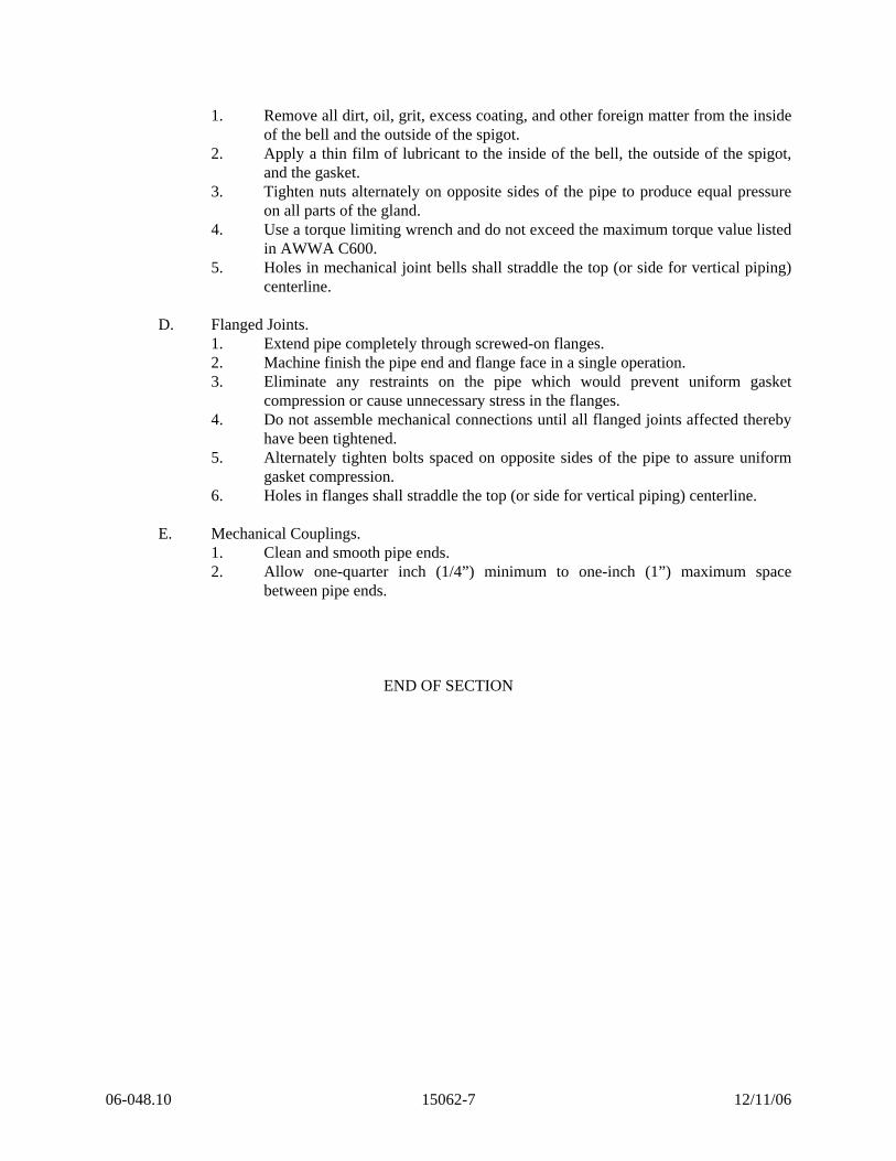
1. Remove all dirt, oil, grit, excess coating, and other foreign matter from the inside of the bell and the outside of the spigot.
2. Apply a thin film of lubricant to the inside of the bell, the outside of the spigot, and the gasket.
3. Tighten nuts alternately on opposite sides of the pipe to produce equal pressure on all parts of the gland.
4. Use a torque limiting wrench and do not exceed the maximum torque value listed in AWWA C600.
5. Holes in mechanical joint bells shall straddle the top (or side for vertical piping) centerline.
D. Flanged Joints.
1. Extend pipe completely through screwed-on flanges. 2. Machine finish the pipe end and flange face in a single operation. 3. Eliminate any restraints on the pipe which would prevent uniform gasket
compression or cause unnecessary stress in the flanges. 4. Do not assemble mechanical connections until all flanged joints affected thereby
have been tightened. 5. Alternately tighten bolts spaced on opposite sides of the pipe to assure uniform
gasket compression. 6. Holes in flanges shall straddle the top (or side for vertical piping) centerline.
E. Mechanical Couplings.
1. Clean and smooth pipe ends. 2. Allow one-quarter inch (1/4”) minimum to one-inch (1”) maximum space
between pipe ends.
END OF SECTION
06-048.10 15062-7 12/11/06
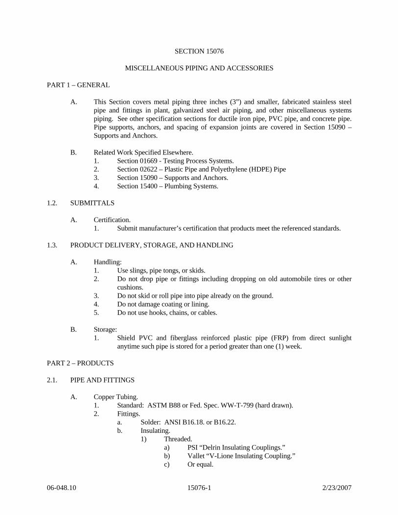
SECTION 15076
MISCELLANEOUS PIPING AND ACCESSORIES PART 1 – GENERAL
A. This Section covers metal piping three inches (3”) and smaller, fabricated stainless steel pipe and fittings in plant, galvanized steel air piping, and other miscellaneous systems piping. See other specification sections for ductile iron pipe, PVC pipe, and concrete pipe. Pipe supports, anchors, and spacing of expansion joints are covered in Section 15090 – Supports and Anchors.
B. Related Work Specified Elsewhere.
1. Section 01669 - Testing Process Systems. 2. Section 02622 – Plastic Pipe and Polyethylene (HDPE) Pipe 3. Section 15090 – Supports and Anchors. 4. Section 15400 – Plumbing Systems.
1.2. SUBMITTALS
A. Certification. 1. Submit manufacturer’s certification that products meet the referenced standards.
1.3. PRODUCT DELIVERY, STORAGE, AND HANDLING
A. Handling: 1. Use slings, pipe tongs, or skids. 2. Do not drop pipe or fittings including dropping on old automobile tires or other
cushions. 3. Do not skid or roll pipe into pipe already on the ground. 4. Do not damage coating or lining. 5. Do not use hooks, chains, or cables.
B. Storage:
1. Shield PVC and fiberglass reinforced plastic pipe (FRP) from direct sunlight anytime such pipe is stored for a period greater than one (1) week.
PART 2 – PRODUCTS 2.1. PIPE AND FITTINGS
A. Copper Tubing. 1. Standard: ASTM B88 or Fed. Spec. WW-T-799 (hard drawn). 2. Fittings.
a. Solder: ANSI B16.18. or B16.22. b. Insulating.
1) Threaded. a) PSI “Delrin Insulating Couplings.” b) Vallet “V-Lione Insulating Coupling.” c) Or equal.
06-048.10 15076-1 2/23/2007

2) Flanged. a) Epco, “Dielectric Flange Unions.” b) PSI “Type E Flange Insulation.” c) Or equal.
3. Solder. a. Solid wire. b. ASTM B32. c. Alloy Grade 50A (50-50).
B. PVC & CPVC Pipe, one-eighth inch to eighteen inches (1/8”- 18”).
1. Pressure pipe. a. ASTM D1784, ASTM D1785, Schedule 80 PVC. b. ASTM F441, Schedule 80 CPVC
2. Drain piping (above grade). a. ASTM D1784, ASTM D1785, Schedule 80, PVC. b. ASTM F441, Schedule 80 CPVC
3. Overflow piping. a. ASTM D1784, ASTM D1785, Schedule 40 PVC.
4. Fittings. a. ASTM D1784, ASTM D2464, ASTM D2467, ASTM F437, ASTM F439. b. Schedule 80 PVC and Schedule 80 CPVC.
1) Spears. 2) Celanese. 3) Or equal.
5. Flanges. a. Diameter and drilling to conform to ANSI B16.5. b. ASTM D2467. c. Class 150 rated at one hundred fifty pounds per square inch (150 psi).
1) Flange Bolts, Flat Washers, Lock Washers, and Nuts. a) ASTM A307. b) Grade B. c) Zinc or cadmium plated.
2) Flange Gaskets. a) Full face. b) One-eighth inch (1/8”) thick. c) Neoprene or plasticized PVC.
6. Joints. a. Piping, one-eighth inch to four inches (1/8” – 4”); solvent weld. b. Piping, six inch to eighteen inches (6” – 18”); welded joints.
C. Black Steel or Hot-Dipped Zinc-Coated (Galvanized) Pipe, one-eighth inch to twelve inches
(1/8”-12”). All process air piping shall be Hot Dipped Zinc Coated (Galvanized) Pipe. 1. Pipe.
a. ASTM A120. b. Schedule 40. c. Seamless or welded.
2. Fittings. a. Malleable iron or fabricated Hot Dipped Galvanized. b. ANSI B16.3. c. Type II (galvanized) for galvanized pipe.
06-048.10 15076-2 2/23/2007

d. Type I (black) for black steel pipe. 3. Flanges.
a. ANSI B16.1. 1) One hundred twenty-five pounds (125 lbs.).
b. ANSI B16.5. 2) One hundred fifty pounds (150 lbs.).
D. Soil Pipe.
1. Below building floor slabs. a. Cast Iron. b. ASTM A74. c. Service weight B & S. d. Elastomeric joints.
2. Above grade. a. Cast Iron. b. ASTM A74. c. Service weight B & S or hubless. d. CISPI 301 with elastomeric joints. e. Galvanized steel.
1) ASTM A120 (Schedule 40). 2) Malleable iron drainage fittings. 3) ANSI B16.3. Type II (galvanized).
a. Copper DWV pipe and fittings with 50/50 solder joints. 3. Manufacturers.
a. Tyler Pipe. b. Or equal.
E. Vent Pipe.
1. Below grade. a. Cast Iron. b. ASTM A74. c. Service weight B & S elastomeric joints.
2. Above grade. a. Cast Iron. b. ASTM A74. c. Service weight B & S or hubless. d. CISPI 301 with elastomeric joints. e. Galvanized steel.
1) ASTM A120 with galvanized C.I. steam pattern or malleable iron fittings.
f. Copper DWV pipe and fittings with 50/50 solder joints. F. Domestic Water Pipe.
1. Type “L” hard drawn copper with wrought copper sweat fittings with 50/50 solder joints.
2. Type “K” copper with flared fittings for buried service. G. Stainless Steel Pipe.
1. Type 316L stainless steel or type 304 stainless steel as designated on Drawings. 2. Schedule 10 or as noted on Drawings.
06-048.10 15076-3 2/23/2007
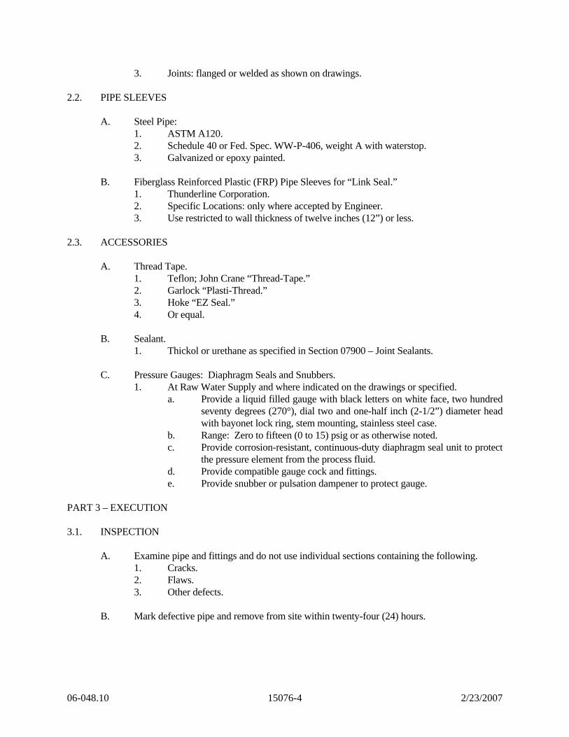
3. Joints: flanged or welded as shown on drawings. 2.2. PIPE SLEEVES
A. Steel Pipe: 1. ASTM A120. 2. Schedule 40 or Fed. Spec. WW-P-406, weight A with waterstop. 3. Galvanized or epoxy painted.
B. Fiberglass Reinforced Plastic (FRP) Pipe Sleeves for “Link Seal.”
1. Thunderline Corporation. 2. Specific Locations: only where accepted by Engineer. 3. Use restricted to wall thickness of twelve inches (12”) or less.
2.3. ACCESSORIES
A. Thread Tape. 1. Teflon; John Crane “Thread-Tape.” 2. Garlock “Plasti-Thread.” 3. Hoke “EZ Seal.” 4. Or equal.
B. Sealant.
1. Thickol or urethane as specified in Section 07900 – Joint Sealants. C. Pressure Gauges: Diaphragm Seals and Snubbers.
1. At Raw Water Supply and where indicated on the drawings or specified. a. Provide a liquid filled gauge with black letters on white face, two hundred
seventy degrees (270°), dial two and one-half inch (2-1/2”) diameter head with bayonet lock ring, stem mounting, stainless steel case.
b. Range: Zero to fifteen (0 to 15) psig or as otherwise noted. c. Provide corrosion-resistant, continuous-duty diaphragm seal unit to protect
the pressure element from the process fluid. d. Provide compatible gauge cock and fittings. e. Provide snubber or pulsation dampener to protect gauge.
PART 3 – EXECUTION 3.1. INSPECTION
A. Examine pipe and fittings and do not use individual sections containing the following. 1. Cracks. 2. Flaws. 3. Other defects.
B. Mark defective pipe and remove from site within twenty-four (24) hours.
06-048.10 15076-4 2/23/2007
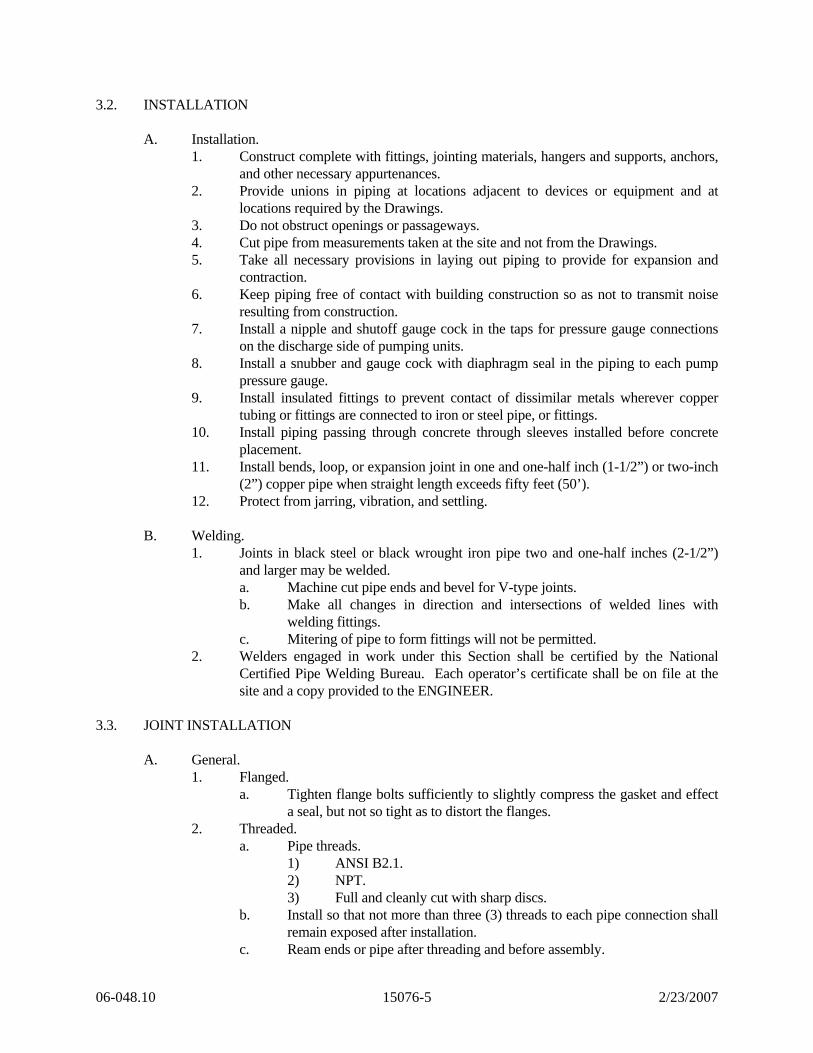
3.2. INSTALLATION
A. Installation. 1. Construct complete with fittings, jointing materials, hangers and supports, anchors,
and other necessary appurtenances. 2. Provide unions in piping at locations adjacent to devices or equipment and at
locations required by the Drawings. 3. Do not obstruct openings or passageways. 4. Cut pipe from measurements taken at the site and not from the Drawings. 5. Take all necessary provisions in laying out piping to provide for expansion and
contraction. 6. Keep piping free of contact with building construction so as not to transmit noise
resulting from construction. 7. Install a nipple and shutoff gauge cock in the taps for pressure gauge connections
on the discharge side of pumping units. 8. Install a snubber and gauge cock with diaphragm seal in the piping to each pump
pressure gauge. 9. Install insulated fittings to prevent contact of dissimilar metals wherever copper
tubing or fittings are connected to iron or steel pipe, or fittings. 10. Install piping passing through concrete through sleeves installed before concrete
placement. 11. Install bends, loop, or expansion joint in one and one-half inch (1-1/2”) or two-inch
(2”) copper pipe when straight length exceeds fifty feet (50’). 12. Protect from jarring, vibration, and settling.
B. Welding.
1. Joints in black steel or black wrought iron pipe two and one-half inches (2-1/2”) and larger may be welded. a. Machine cut pipe ends and bevel for V-type joints. b. Make all changes in direction and intersections of welded lines with
welding fittings. c. Mitering of pipe to form fittings will not be permitted.
2. Welders engaged in work under this Section shall be certified by the National Certified Pipe Welding Bureau. Each operator’s certificate shall be on file at the site and a copy provided to the ENGINEER.
3.3. JOINT INSTALLATION
A. General. 1. Flanged.
a. Tighten flange bolts sufficiently to slightly compress the gasket and effect a seal, but not so tight as to distort the flanges.
2. Threaded. a. Pipe threads.
1) ANSI B2.1. 2) NPT. 3) Full and cleanly cut with sharp discs.
b. Install so that not more than three (3) threads to each pipe connection shall remain exposed after installation.
c. Ream ends or pipe after threading and before assembly.
06-048.10 15076-5 2/23/2007
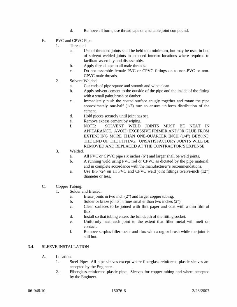
d. Remove all burrs, use thread tape or a suitable joint compound.
B. PVC and CPVC Pipe. 1. Threaded.
a. Use of threaded joints shall be held to a minimum, but may be used in lieu of solvent welded joints in exposed interior locations where required to facilitate assembly and disassembly.
b. Apply thread tape to all male threads. c. Do not assemble female PVC or CPVC fittings on to non-PVC or non-
CPVC male threads. 2. Solvent Welded.
a. Cut ends of pipe square and smooth and wipe clean. b. Apply solvent cement to the outside of the pipe and the inside of the fitting
with a small paint brush or dauber. c. Immediately push the coated surface snugly together and rotate the pipe
approximately one-half (1/2) turn to ensure uniform distribution of the cement.
d. Hold pieces securely until joint has set. e. Remove excess cement by wiping. f. NOTE: SOLVENT WELD JOINTS MUST BE NEAT IN
APPEARANCE. AVOID EXCESSIVE PRIMER AND/OR GLUE FROM EXTENDING MORE THAN ONE-QUARTER INCH (1/4”) BEYOND THE END OF THE FITTING. UNSATISFACTORY JOINTS WILL BE REMOVED AND REPLACED AT THE CONTRACTOR’S EXPENSE.
3. Welded. a. All PVC or CPVC pipe six inches (6”) and larger shall be weld joints. b. A running weld using PVC rod or CPVC as dictated by the pipe material,
and in complete accordance with the manufacturer’s recommendations. a. Use IPS 724 on all PVC and CPVC weld joint fittings twelve-inch (12”)
diameter or less. C. Copper Tubing.
1. Solder and Brazed. a. Braze joints in two inch (2”) and larger copper tubing. b. Solder or braze joints in lines smaller than two inches (2”). c. Clean surfaces to be joined with flint paper and coat with a thin film of
flux. d. Install so that tubing enters the full depth of the fitting socket. e. Uniformly heat each joint to the extent that filler metal will melt on
contact. f. Remove surplus filler metal and flux with a rag or brush while the joint is
still hot. 3.4. SLEEVE INSTALLATION
A. Location. 1. Steel Pipe: All pipe sleeves except where fiberglass reinforced plastic sleeves are
accepted by the Engineer. 2. Fiberglass reinforced plastic pipe: Sleeves for copper tubing and where accepted
by the Engineer.
06-048.10 15076-6 2/23/2007
B. General.
1. Install pipe sleeves so they project two inches (2”) above the floor surface where pipes pass through floors.
2. Consideration will be given by ENGINEER to holes drilled with a suitable rotary drill in lieu of sleeves for piping which pass through interior walls.
3.5. PIPE TESTING
A. Furnish testing equipment. B. Test piping systems in presence of ENGINEER. C. Isolate fixtures and equipment subject to damage from test performance. D. Test Requirements.
1. Domestic hot and cold water: Eight (8) hour hydrostatic test at 150 psig. 3.6. CLEANING
A. Inside of pipe, valves, and fittings: Smooth, clean, and free from blisters, loose mill scale, sand, and dirt when erected.
B. Blow lines thoroughly with clean, dry air before placing in service.
END OF SECTION
06-048.10 15076-7 2/23/2007
SECTION 15090
SUPPORTS AND ANCHORS PART 1 – GENERAL 1.1. DESCRIPTION
A. This Section covers pipe hangers, brackets, supports, U-bolts, clamps, anchors, and accessories. 1. Install complete with necessary inserts, bolts, nuts, rods, and washers.
1.2. QUALITY ASSURANCE
A. Reference Standards. 1. Pipe Supports: Fed. Spec. WW-H-171.
1.3. SUBMITTALS
A. Submit certification that materials meet requirements of referenced standards. 1.4. PRODUCT DELIVERY, STORAGE, AND HANDLING
A. Package pipe support materials as necessary to ensure delivery in satisfactory condition. B. Store modular rubber sealing units in a cool, dark location, removed from grease, oil, and
other harmful substances. C. Protect from exposure to elements and keep thoroughly dry. D. Store off of ground in weather tight enclosure.
PART 2 – PRODUCTS 2.1. DESIGN REQUIREMENTS
A. Contact between Dissimilar Metals. 1. Prevent contact between dissimilar metals when supporting copper tubing.
a. Coat portions of pipe supports in contact with the tubing by copper plating, rubber or vinyl coating, or stainless steel.
B. Pipe Supports.
1. Where the abbreviation PS (pipe support) appears on the Drawings, the pipe shall be supported with the pipe support listed and shown on the Drawings. a. Rod, clevis, or bracket must meet Federal Specification WW-H-171. b. Adjustable Pipe Saddle Support: Anvil International, Inc. – Figure 265 –
Size 4” through 36”, or equal. c. Adjustable Clevis Hanger for Ductile Iron or Cast Iron Pipe: Anvil
International, Inc. – Figure 590 – Size 4” through 24”, or equal.
06-048.10 15090-1 11/9/06
d. Adjustable Pipe Roll Support: Anvil International, Inc. – Figure 171 30” Size with 2 each 1-1/2-inch Rods and angle hangers for 11/2-inch rods, or equal. (See Details.)
e. Wall Brackets, Heavy Duty: Anvil International, Inc. – Figure 199, Size 4, or equal. Provide “U” bolt strap where shown on the Drawings.
2. Where a letter follows the abbreviation for pipe supports (i.e., PS-A), the unit is to be fabricated as detailed on the Drawings.
3. Use appropriate size and type for small mechanical piping. C. Pipe Anchors (PA).
1. PA designations are detailed on the Drawings. 2.2. ACCESSORIES
A. Threaded inserts for cast-in-place application (for loads greater than one thousand five hundred pounds (1500 lbs.)). 1. Hohman and Barnard, Type HFH, or equal.
a. Center #6 by two feet six inches (#6 x 2’6”) rebar through insert loop. B. Other inserts for cast-in-place application (for loads less than one thousand five hundred
pounds (1500 lbs.)). 1. Federal Specification WW-H-171, Type 18, malleable iron.
a. Center #4 by two feet zero inches (#4 x 2’0”) rebar through opening. 2. Continuous twelve (12) gauge, galvanized, twelve inches (12”) length (minimum).
a. Unistrut P3253, through unistrut 3261, or equal. C. Bolts: ASTM 307. D. Threaded Rods.
1. ASTM A36, ASTM 575, or ASTM 576. a. Minimum rod diameter and maximum safe load on rods, reference MSS
SP-58 and MSS SP-69. PART 3 – EXECUTION 3.1. LOCATION AND SPACING OF SUPPORTS
A. Location of Pipe Supports and Anchors. 1. In certain locations, pipe supports, and anchors may be shown on the Drawings; but
no attempt has been made to indicate every pipe support and anchor. 2. Provide a complete system of pipe supports, and anchor all piping. Provide swing
joints to permit free expansion and contraction without causing undue stresses, springing, or forcing, and so pipe weight will not be supported by equipment.
3. Maximum straight run of PVC piping without expansion joint, loop, or bends, shall be twenty feet (20’).
4. Where bends are used to provide for expansion in PVC piping, provide sufficient length of straight pipe between bends for piping to move laterally to absorb the expansion.
5. Additional pipe supports may be required adjacent to expansion points or couplings.
06-048.10 15090-2 11/9/06
6. Rigidly support and anchor piping so there is no movement or visible sagging between supports.
7. Pipe supports and expansion joints are not required in buried piping. 8. Provide concrete blocking for buried piping acceptable to ENGINEER. 9. Maintain uniform grade where required.
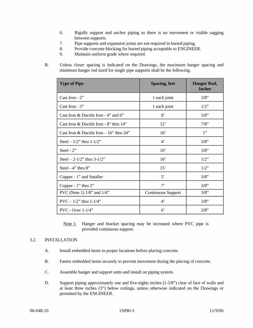
B. Unless closer spacing is indicated on the Drawings, the maximum hanger spacing and
minimum hanger rod sized for single pipe supports shall be the following.
Type of Pipe Spacing, feet Hanger Rod, Inches
Cast Iron - 2” 1 each joint 3/8”
Cast Iron - 3” 1 each joint 1/2”
Cast Iron & Ductile Iron - 4” and 6” 8’ 5/8”
Cast Iron & Ductile Iron - 8” thru 14” 12’ 7/8”
Cast Iron & Ductile Iron – 16” thru 24” 16’ 1”
Steel – 1/2” thru 1-1/2” 4’ 3/8”
Steel - 2” 10’ 3/8”
Steel – 2-1/2” thru 3-1/2” 10’ 1/2”
Steel - 4” thru 8” 15’ 1/2”
Copper - 1” and Smaller 5’ 3/8”
Copper - 1” thru 2” 7’ 3/8” PVC (Note 1) 1/8” and 1/4” Continuous Support 3/8”
PVC – 1/2” thru 1-1/4” 4’ 3/8”
PVC - Over 1-1/4” 6’ 3/8”
Note 1: Hanger and bracket spacing may be increased where PVC pipe is provided continuous support.
3.2. INSTALLATION
A. Install embedded items in proper locations before placing concrete. B. Fasten embedded items securely to prevent movement during the placing of concrete. C. Assemble hanger and support units and install on piping system. D. Support piping approximately one and five-eights inches (1-5/8”) clear of face of walls and
at least three inches (3”) below ceilings, unless otherwise indicated on the Drawings or permitted by the ENGINEER.
06-048.10 15090-3 11/9/06
E. Install hangers on cast iron soil pipe as recommended by Cast Iron Soil Institute Pamphlet
No. 100 and Cast Iron Soil Pipe Volume No. 1. 3.3. APPLICATION
A. Use cast-in-place concrete inserts to support piping from new cast-in-place concrete. B. Use wedge type expansion anchors to fasten pipe supports to existing concrete.
1. Maximum working load to be less than one-quarter (1/4) proof test load listed in Federal Specification FF-S-325.
C. Use pipe supports manufactured for the size and type of pipe to which they apply. D. Provide zinc or cadmium plated threaded rods with sufficient threading to permit the
maximum adjustment available in the support item. E. Strap hangers, wire, perforated metal, or chains will not be acceptable. F. Maintain required grading, prevent vibration, and provide for expansion and contraction. G. Hangers and supports not shown on the Drawings for small piping.
1. Support and anchor to prevent sagging, pocketing, swaying, and displacement.
END OF SECTION
06-048.10 15090-4 11/9/06

SECTION 15100
MISCELLANEOUS VALVES PART 1 – GENERAL 1.1. DESCRIPTION
A. This Section covers furnishing and installing miscellaneous valves not otherwise covered in other sections. 1. Provide at locations shown on the Drawings or described in the Contract
Documents. 2. Provide complete with all jointing materials and appurtenances.
1.2. QUALITY ASSURANCE
A. Perform all work as specified herein and in accordance with the latest revisions of the following codes and standards. 1. Federal, State, and Local codes, regulations and ordinances. 2. American National Standard Institute (ANSI). 3. American Water Works Association (AWWA). 4. American Society for Testing and Materials (ASTM). 5. American Society of Mechanical Engineers (ASME). 6. Manufacturers Standardization Society of the Valve and Fitting Industry (MSS).
B. In case of conflict or disagreement between codes, standards, laws, ordinances, rules and
regulations, or within any document itself, the more stringent requirements as determined by Engineer shall govern. 1. Where work required by the drawings and specifications is above the standard
required by local regulations or recommended standards, it shall be completed as shown and/or specified.
1.3. RELATED WORK
A. Consult all other Specification sections, determine the extent and character of related work, and properly coordinate work specified herein with that specified elsewhere to produce a complete operational installation.
1.4. SUBMITTALS
A. Submit the information identified by the following Data Reference Symbols as specified in Section 01340 - Shop Drawings, Samples, and Operation and Maintenance Manuals. 1. Shop Drawings: A, C, E, H, L, and N. 2. Operation and Maintenance Manual: F, H, L, M, and N.
1.5. PRODUCT DELIVERY, STORAGE, AND HANDLING
A. Take precaution to avoid damage to valves and appurtenances during delivery, storage, and handling.
06-048.10 15100-1 11/10/06
B. Store valves off of ground in a weathertight enclosure at a maintained minimum temperature of fifty degrees Fahrenheit (50° F.)
C. Keep joints and internal parts clean.
PART 2 – PRODUCTS 2.1. GENERAL
A. Operators. 1. Provide manual operators except where power-actuated or automatic-operating
valves are indicated. 2. Provide each manual operator with a handwheel unless indicated otherwise, or
unless the valve is buried. 3. Provide buried valves with valve box and cover. 4. Open: Left (Counterclockwise).
B. Cast directional arrow and “OPEN” in valve body and operator. C. End Connections.
1. Unless otherwise specified or indicated on the Drawings, provide valves with: a. Mechanical ends for buried locations.
1) ANSI/AWWA C111/A21.11. b. Flanged ends for exposed locations.
1) ASME/ANSI B16.1, Class 125. 2.2. BRONZE BALL VALVES
A. All shut-off valves two and one-half inches (2-1/2”) and smaller are ball valves except where specified or indicated otherwise.
B. Standard: MSS SP-110. C. Types.
1. 150 psi W.S.P. 2. 400 psi non-shock W.O.G.
D. Construction.
1. Quarter-Turn Lever Operator (vinyl coated). 2. Two-Piece Body. 3. Blow-out Proof Stem. 4. Swing-away Design. 5. Full port. 6. Design shall allow downstream pipe to be disconnected under full pressure. 7. Bubble tight shut-off required.
E. Material.
1. Bronze, ASTM B283: Stem, ball (chrome-plated), body, body end pieces. 2. Plated Steel, ASTM A 36: Handle and nut. 3. Reinforced TFE: Packing, thrust washer, seats.
06-048.10 15100-2 11/10/06

F. End Connections.
1. Use threaded connections as specified herein or indicated in the Drawings. a. Threaded Ends: Hammond. b. Or equal.
G. Manufacturers.
1. Red-White Valve. 2. Hammond. 3. Nibco. 4. Or equal.
H. For chemical, liquid, or gas service, select valves specifically designated by appropriate
standards for that service. 2.3. PVC BALL VALVES
A. Use PVC valves when installed in PVC pipe. B. All shut-off valves two and one-half inches (2-1/2”) and smaller are ball valves except
where specified or indicated otherwise. C. Standard: PVC Type I Cell Classification 12454 conforming to ASTM D-1784. D. Rating:
1. One-half inch through two inch (1/2” thru 2”): Rated at 235 psi at seventy-three degrees Fahrenheit (73° F.).
2. Two and one-half inch (2’-1/2”): Rated at 150 psi at seventy-three degrees Fahrenheit (73° F.).
E. Certification: National Sanitation Foundation (NSF) certification for potable water is
required. F. Construction:
1. Quarter-turn operation. 2. True Union Body. 3. O-Rings: EPDM or Viton. Use Viton for Sodium Hypochlorite Service. 4. Handles: Double stop polypropylene. 5. Full port with opening diameter not less than the ID of Schedule 80 PVC pipe of
the corresponding nominal pipe size. 6. Design shall allow downstream pipe to be disconnected under full pressure. 7. Ball Seats: Polytetrafluorethylene (PTFE), e.g. Teflon. 8. Ball: Balls for sodium hypochlorite to be vented upstream. 9. Bubble tight shut off required.
G. End Connections.
1. Use socket weld connections as specified herein or indicated on the Drawings. 2. Do not assemble female PVC threaded valve to male non-PVC mating fixture or
piping.
06-048.10 15100-3 11/10/06
H. Manufacturers. 1. Spears. 2. Chemtrol. 3. Chemline. 4. Or equal.
I. Manufacturers for Sodium Hypochlorite Service
1. Spears True Union 2000 Vented Ball Valves. 2. Or equal.
J. For chemical, liquid, or gas service, select valves specifically designated by appropriate
standards for that service. 2.4. SWING CHECK VALVES (THREE INCH (3”) AND SMALLER)
A. General. 1. Resilient seat, swing check design. 2. Full port design with opening diameter not less than ID of Schedule 80 PVC pipe. 3. Standard: MSS SP-80. 4. Pressure:
a. 150 psi W.S.P. b. 300 psi non-shock W.O.G.
5. Design to allow replacement of internal components without removing from line. B. Material.
1. Body, Bonnet, Disc Seat, Disc Arm, Disc, and Bushings. a. Bronze, ASTM B 62.
2. Hinges, Pins, and Seat Bolt. a. Stainless Steel, ASTM A 276 Type 304.
3. Gaskets, O-Rings, and Disc Seat. a. Buna-N Rubber, ASTM D 2000.
C. End Connections.
1. Use threaded connections as specified herein or indicated on the Drawings. a. Threaded Ends: Hammond. b. Or equal.
D. Manufacturers.
1. Red-White Valve. 2. Watts Regulator. 3. Hammond. 4. Or equal.
2.5. BALL CHECK VALVES (ONE-HALF-INCH TO FOUR-INCH (1/2” – 4”))
A. General. 1. Ball check design. 2. Free floating ball. 3. Capable of mounting in vertical or horizontal position.
06-048.10 15100-4 11/10/06

4. Pressure: One-half to two-inch (1/2” - 2”) – 150 psi. ; two and one-half to four inch (2-1/2” – 4”) – 100 psi.
B. Material.
1. PVC body 2. EPDM seal. 3. PVC ball.
C. End Connections.
1. Socket ends. D. Manufacturers.
1. Chemline. 2. Or equal.
2.6. WAFER CHECK VALVE (TWO-INCH TO TWELVE-INCH (2” – 12”))
A. General. 1. Resilient seated, double disc design. 2. Dual corrosion-resistant springs 3. Fully elastomer lined. 4. Capable of mounting in vertical or horizontal position. 5. Bubble tight shut off from 25 to 150 psi differential pressure
B. Material.
1. DIP body. 2. EPDM resilient seat. 3. 316 stainless steal plates, shaft, and bearings.
C. End Connections.
1. Wafer style for mounting with ANSI B16.1, class 125 flanges. D. Manufacturers.
1. Centerline. 2. Or equal.
2.7 PLUG VALVES
A. Valves shall be ninety degree (90°) turn, non-lubricated, eccentric type with resilient faced plugs. 1. Valves shall be suitable for throttling service and service where valve operation is
infrequent. 2. Valves shall provide drip-tight shut-off up to full pressure rating with pressure in
either direction. 3. Valves shall be rated at a minimum of 150 psi in accordance with ASTM B16.1. 4. Valves shall have a port area equal to at least eighty percent (80%) of the full pipe
area. B. Materials.
1. Bodies shall be cast-iron conforming to ASTM A126, Class B.
06-048.10 15100-5 11/10/06

2. Valve ends shall be flanged meeting the requirements of ANSI B16.1, Class 125. 3. Valve seats shall be raised, welded-in overlay of not less than ninety percent (90%)
pure nickel, machined to mate with resilient faced plug. 4. Plug shall be semi-steel, conforming to ASTM A126, Class B. 5. Plug facing shall be synthetic rubber compound of approximately seventy (70)
durometer hardness bonded to the plug. 6. Facing material shall be abrasion resistant and suitable for service in potable water
applications. 7. Valves shall be furnished with replaceable, sleeve-type bearings in the upper and
lower journals. 8. Bearings shall comply with applicable requirements of AWWA C507.
C. Operators.
1. Valves shall have a nut type operator. 2. Two (2) valve keys shall be provided for operating the plug valves. 3. Valve keys shall be fabricated to the length necessary to reach the operating nut
with the operating tee handle approximately six inches (6”) above finished floor elevation. (SHORT VALVE KEY).
D. Manufacturers.
1. DeZurik, Keystone, or Equal. 2.8. HOSE VALVES AND DRAIN VALVES
A. Globe Valve Type, three-quarter inch and one-half inch (3/4” & 1/2”). B. Manufacturers:
1. Barrett. 2. Nibco. 3. Prier Brass. 4. Tanner. 5. Or equal.
2.9. SOLENOID VALVES (WATER OR AIR)
A. Bronze body and bonnet, packless construction without packing box or sliding seal. B. Solenoid Coils:
1. 115 volt ac, encapsulated, Class F. 2. For continuous duty at rated voltage plus or minus ten percent (+/- 10%) and forty
degrees Celsius (40° C.) ambient. 3. In NEMA Type 4 enclosure with conduit knockout. 4. Scheduled as normally open (N.O.), normally closed (N.C.) or three-way (TM).
C. Manufacturers:
1. ASCO. 2. Honeywell. 3. Bray. 4. Or equal.
06-048.10 15100-6 11/10/06
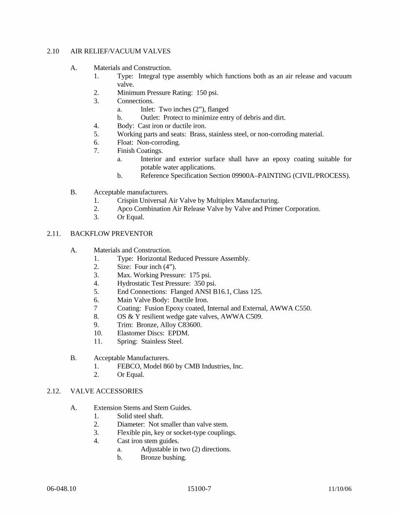
2.10 AIR RELIEF/VACUUM VALVES
A. Materials and Construction. 1. Type: Integral type assembly which functions both as an air release and vacuum
valve. 2. Minimum Pressure Rating: 150 psi. 3. Connections.
a. Inlet: Two inches (2”), flanged b. Outlet: Protect to minimize entry of debris and dirt.
4. Body: Cast iron or ductile iron. 5. Working parts and seats: Brass, stainless steel, or non-corroding material. 6. Float: Non-corroding. 7. Finish Coatings.
a. Interior and exterior surface shall have an epoxy coating suitable for potable water applications.
b. Reference Specification Section 09900A–PAINTING (CIVIL/PROCESS). B. Acceptable manufacturers.
1. Crispin Universal Air Valve by Multiplex Manufacturing. 2. Apco Combination Air Release Valve by Valve and Primer Corporation. 3. Or Equal.
2.11. BACKFLOW PREVENTOR
A. Materials and Construction. 1. Type: Horizontal Reduced Pressure Assembly. 2. Size: Four inch (4”). 3. Max. Working Pressure: 175 psi. 4. Hydrostatic Test Pressure: 350 psi. 5. End Connections: Flanged ANSI B16.1, Class 125. 6. Main Valve Body: Ductile Iron. 7 Coating: Fusion Epoxy coated, Internal and External, AWWA C550. 8. OS & Y resilient wedge gate valves, AWWA C509. 9. Trim: Bronze, Alloy C83600. 10. Elastomer Discs: EPDM. 11. Spring: Stainless Steel.
B. Acceptable Manufacturers.
1. FEBCO, Model 860 by CMB Industries, Inc. 2. Or Equal.
2.12. VALVE ACCESSORIES
A. Extension Stems and Stem Guides. 1. Solid steel shaft. 2. Diameter: Not smaller than valve stem. 3. Flexible pin, key or socket-type couplings. 4. Cast iron stem guides.
a. Adjustable in two (2) directions. b. Bronze bushing.
06-048.10 15100-7 11/10/06
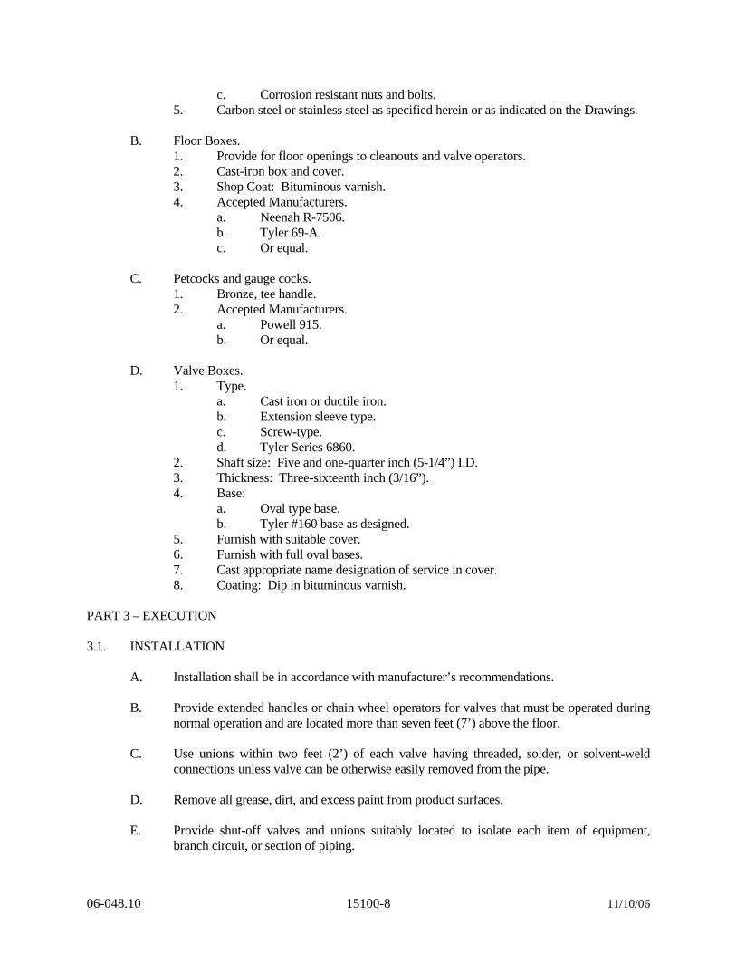
c. Corrosion resistant nuts and bolts. 5. Carbon steel or stainless steel as specified herein or as indicated on the Drawings.
B. Floor Boxes.
1. Provide for floor openings to cleanouts and valve operators. 2. Cast-iron box and cover. 3. Shop Coat: Bituminous varnish. 4. Accepted Manufacturers.
a. Neenah R-7506. b. Tyler 69-A. c. Or equal.
C. Petcocks and gauge cocks.
1. Bronze, tee handle. 2. Accepted Manufacturers.
a. Powell 915. b. Or equal.
D. Valve Boxes.
1. Type. a. Cast iron or ductile iron. b. Extension sleeve type. c. Screw-type. d. Tyler Series 6860.
2. Shaft size: Five and one-quarter inch (5-1/4”) I.D. 3. Thickness: Three-sixteenth inch (3/16”). 4. Base:
a. Oval type base. b. Tyler #160 base as designed.
5. Furnish with suitable cover. 6. Furnish with full oval bases. 7. Cast appropriate name designation of service in cover. 8. Coating: Dip in bituminous varnish.
PART 3 – EXECUTION 3.1. INSTALLATION
A. Installation shall be in accordance with manufacturer’s recommendations. B. Provide extended handles or chain wheel operators for valves that must be operated during
normal operation and are located more than seven feet (7’) above the floor. C. Use unions within two feet (2’) of each valve having threaded, solder, or solvent-weld
connections unless valve can be otherwise easily removed from the pipe. D. Remove all grease, dirt, and excess paint from product surfaces. E. Provide shut-off valves and unions suitably located to isolate each item of equipment,
branch circuit, or section of piping.
06-048.10 15100-8 11/10/06
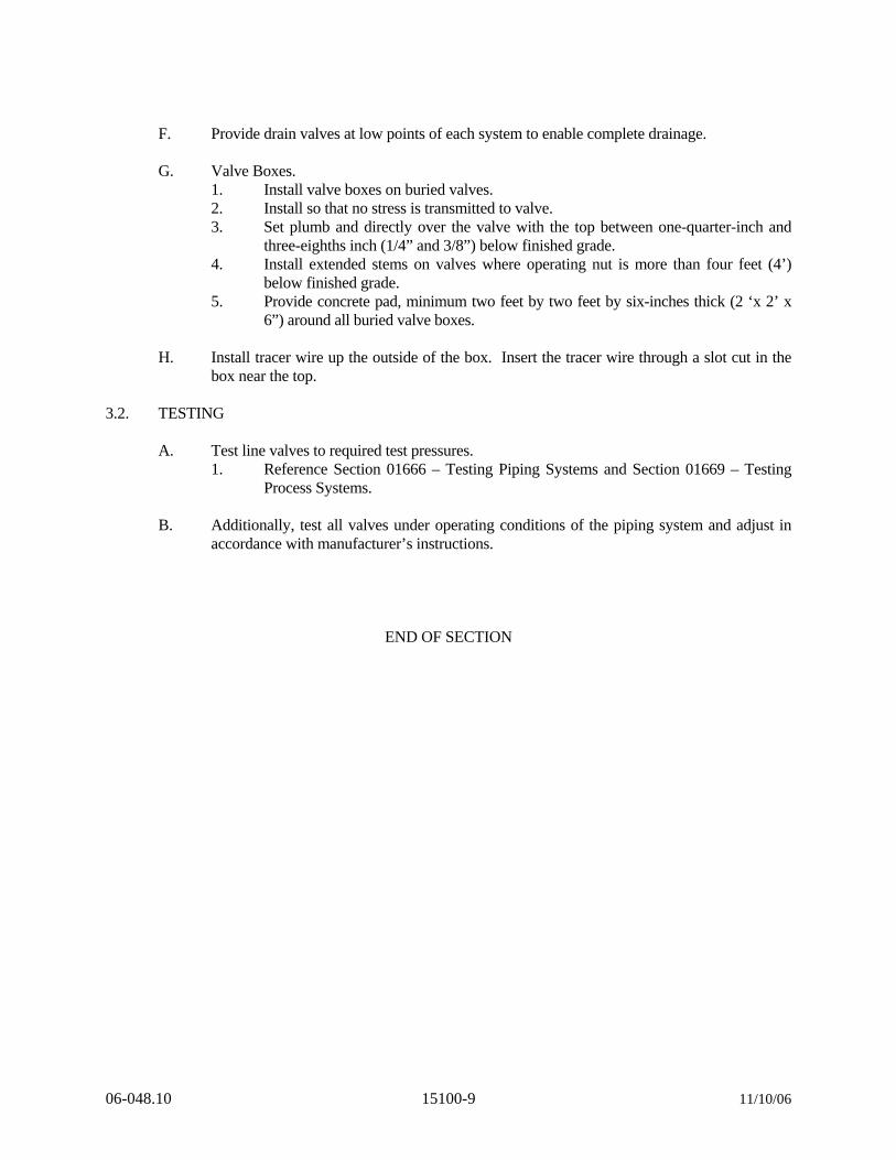
F. Provide drain valves at low points of each system to enable complete drainage. G. Valve Boxes.
1. Install valve boxes on buried valves. 2. Install so that no stress is transmitted to valve. 3. Set plumb and directly over the valve with the top between one-quarter-inch and
three-eighths inch (1/4” and 3/8”) below finished grade. 4. Install extended stems on valves where operating nut is more than four feet (4’)
below finished grade. 5. Provide concrete pad, minimum two feet by two feet by six-inches thick (2 ‘x 2’ x
6”) around all buried valve boxes. H. Install tracer wire up the outside of the box. Insert the tracer wire through a slot cut in the
box near the top. 3.2. TESTING
A. Test line valves to required test pressures. 1. Reference Section 01666 – Testing Piping Systems and Section 01669 – Testing
Process Systems. B. Additionally, test all valves under operating conditions of the piping system and adjust in
accordance with manufacturer’s instructions.
END OF SECTION
06-048.10 15100-9 11/10/06
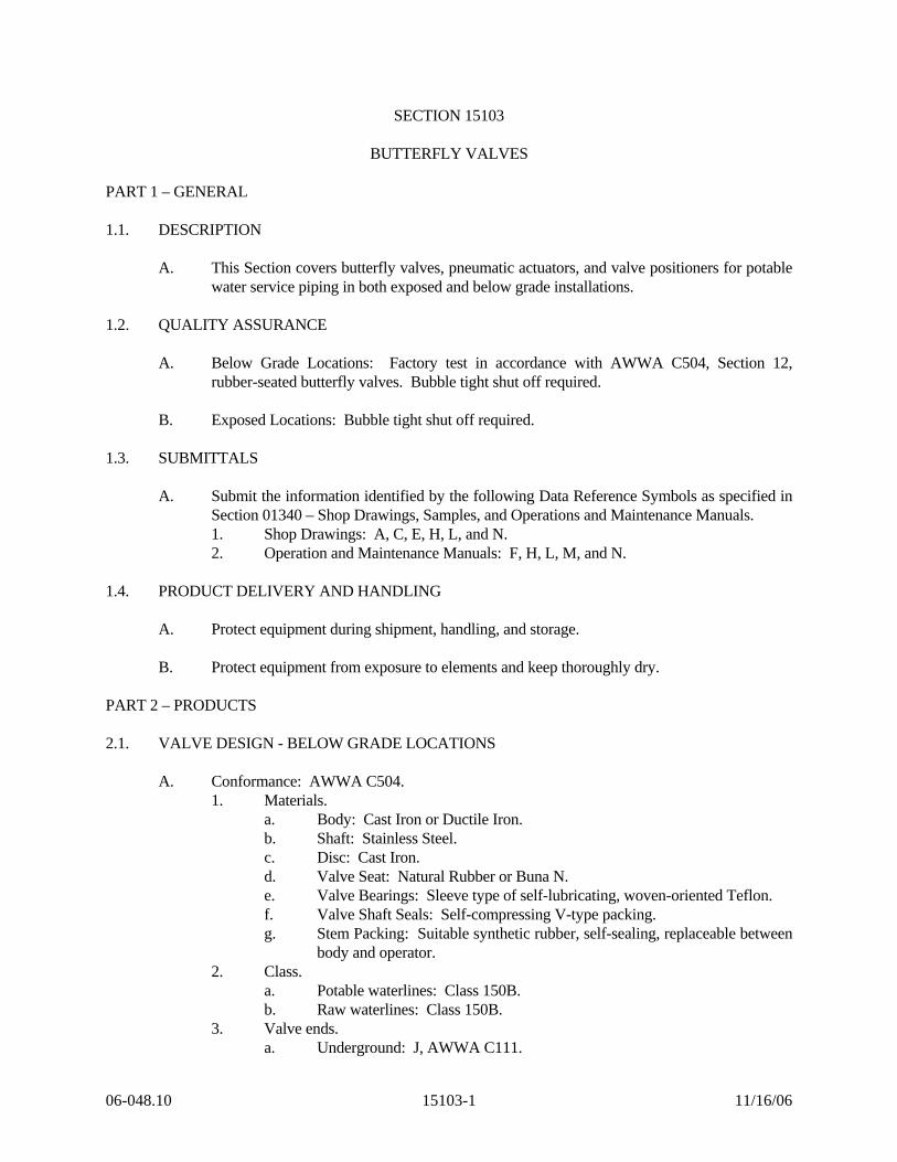
SECTION 15103
BUTTERFLY VALVES PART 1 – GENERAL 1.1. DESCRIPTION
A. This Section covers butterfly valves, pneumatic actuators, and valve positioners for potable water service piping in both exposed and below grade installations.
1.2. QUALITY ASSURANCE
A. Below Grade Locations: Factory test in accordance with AWWA C504, Section 12, rubber-seated butterfly valves. Bubble tight shut off required.
B. Exposed Locations: Bubble tight shut off required.
1.3. SUBMITTALS
A. Submit the information identified by the following Data Reference Symbols as specified in Section 01340 – Shop Drawings, Samples, and Operations and Maintenance Manuals. 1. Shop Drawings: A, C, E, H, L, and N. 2. Operation and Maintenance Manuals: F, H, L, M, and N.
1.4. PRODUCT DELIVERY AND HANDLING
A. Protect equipment during shipment, handling, and storage. B. Protect equipment from exposure to elements and keep thoroughly dry.
PART 2 – PRODUCTS 2.1. VALVE DESIGN - BELOW GRADE LOCATIONS
A. Conformance: AWWA C504. 1. Materials.
a. Body: Cast Iron or Ductile Iron. b. Shaft: Stainless Steel. c. Disc: Cast Iron. d. Valve Seat: Natural Rubber or Buna N. e. Valve Bearings: Sleeve type of self-lubricating, woven-oriented Teflon. f. Valve Shaft Seals: Self-compressing V-type packing. g. Stem Packing: Suitable synthetic rubber, self-sealing, replaceable between
body and operator. 2. Class.
a. Potable waterlines: Class 150B. b. Raw waterlines: Class 150B.
3. Valve ends. a. Underground: J, AWWA C111.
06-048.10 15103-1 11/16/06

4. Maximum Working Pressure. a. Class 150B: 150 psi.
5. Type of shaft seal: O-ring seals. 6. Type of operators.
a. Buried Valves: Two inch (2”) nut. 7. Direction of opening: Open left. 8. Valve and operator arrangement and position.
a. For use in horizontal position. b. Operator horizontal to valve.
9. Operator torque: Reference AWWA C504, Appendix A, design the required operator torque to the higher valve given by the following two formulas. a. To = (Tb + Ts + Th). b. To = (1.2 Tb +/- Td).
10. Protective Coatings. a. All internal and external ferrous surfaces shall be coated with epoxy to a
minimum thickness of 6 mils. The epoxy shall be non-toxic, impart no taste to the water, and shall conform to AWWA C550, latest revision.
11. Approved Manufacturers. a. Mueller. b. Or equal.
2.2. VALVE DESIGN – EXPOSED LOCATIONS
A. Manufacturer: Bray Controls of Houston, Texas. No other manufacturers will be accepted. B. Model: Series 31.
1. Materials and Description. a. General: Valves shall be resilient seat, one-piece, lug style valves in the
sizes and quantities as specified in the Bid Schedule. Flange locating holes shall meet ANSI Class 125/150 drillings
b. Body: Valve body shall be cast iron, ASTM A126 Class B, with a polyester coating. Valve body shall meet ANSI 150 psi pressure ratings. Actuator shall be direct mounted to mounting flange with no adapters where applicable. Valves shall be designed for installation between DIP flanges.
c. Stem: The valve stem shall be one piece, 316 stainless steel, ASTM A276 Type 316. The stem shall be mechanically retained.
d. Disc: Ductile Iron, Nylon 11 coated, ASTM A536 Gr. 65-45-12. The disc shall be machined and hand polished to provide a bubble-tight shut-off. Disc O.D. shall not interfere with adjacent piping when in the fully opened position. The disc to stem connection shall require no additional retention fasteners.
e. Valve Seat: 1) EPDM (food grade). 2) Tongue and groove design with hub seal and molded in O-ring. 3) Totally encapsulated body, no flange gaskets required. 4) The seat to body retention shall provide for easy field replace-
ment with no fasteners. f. Stem Bushing: Acetal, heavy duty. g. Stem Seal: Stem seal shall be self-adjusting with positive bi-directional
sealing.
06-048.10 15103-2 11/16/06
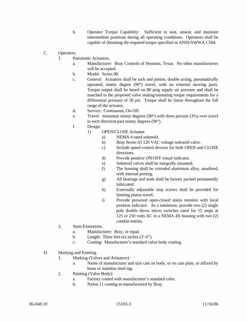
h. Operator Torque Capability: Sufficient to seat, unseat, and maintain intermediate positions during all operating conditions. Operators shall be capable of obtaining the required torque specified in ANSI/AWWA C504.
C. Operators.
1. Pneumatic Actuators. a. Manufacturer: Bray Controls of Houston, Texas. No other manufacturers
will be accepted. b. Model: Series 90. c. General: Actuators shall be rack and pinion, double acting, pneumatically
operated, ninety degree (90°) travel, with no external moving parts. Torque output shall be based on 80 psig supply air pressure and shall be matched to the proposed valve seating/unseating torque requirements for a differential pressure of 50 psi. Torque shall be linear throughout the full range of the actuator.
d. Service: Continuous, On-Off. e. Travel: minimum ninety degrees (90°) with three percent (3%) over travel
in each direction past ninety degrees (90°). f. Design:
1) OPEN/CLOSE Actuator. a) NEMA 4 rated solenoid. b) Bray Series 63 120 VAC voltage solenoid valve. c) Include speed control devices for both OPEN and CLOSE
directions. d) Provide positive ON/OFF visual indicator. e) Solenoid valves shall be integrally mounted. f) The housing shall be extruded aluminum alloy, anodized,
with internal porting. g) All bearings and seals shall be factory packed permanently
lubricated. h) Externally adjustable stop screws shall be provided for
limiting piston travel. i) Provide prewired open-closed status monitor with local
position indicator. As a minimum, provide two (2) single pole double throw micro switches rated for 15 amps at 125 or 250 volts AC in a NEMA 4X housing with two (2) conduit entries.
3. Stem Extensions. a. Manufacturer: Bray, or equal. b. Length: Three feet-six inches (3’-6”). c. Coating: Manufacturer’s standard valve body coating.
D. Marking and Painting.
1. Marking (Valves and Actuators): a. Name of manufacturer and size cast on body, or on cast plate, or affixed by
brass or stainless steel tag. 2. Painting (Valve Body):
a. Factory coated with manufacturer’s standard color. b. Nylon 11 coating as manufactured by Bray.
06-048.10 15103-3 11/16/06
PART 3 – EXECUTION
3.1 DELIVERABLES
A. Quote shall be for supplying valves and actuators per above specifications in the sizes and quantities per the bid schedule. All costs for shipping and handling shall be included in vendor’s bid, F.O.B. Bellvue WTP, 4505 Filter Plant Road, Bellvue, Colorado 80512.
B. Valve and actuator shall be supplied as a unit from one (1) vendor, complete, ready for
installation. C. Vendor shall furnish cut sheets of proposed valves and actuators with quote containing
sufficient detail to assure compliance with the specifications.
06-048.10 15103-4 11/16/06
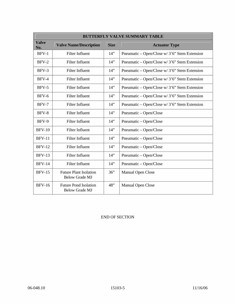
BUTTERFLY VALVE SUMMARY TABLE
Valve No. Valve Name/Description Size Actuator Type
BFV-1 Filter Influent 14” Pneumatic – Open/Close w/ 3’6” Stem Extension
BFV-2 Filter Influent 14” Pneumatic – Open/Close w/ 3’6” Stem Extension
BFV-3 Filter Influent 14” Pneumatic – Open/Close w/ 3’6” Stem Extension
BFV-4 Filter Influent 14” Pneumatic – Open/Close w/ 3’6” Stem Extension
BFV-5 Filter Influent 14” Pneumatic – Open/Close w/ 3’6” Stem Extension
BFV-6 Filter Influent 14” Pneumatic – Open/Close w/ 3’6” Stem Extension
BFV-7 Filter Influent 14” Pneumatic – Open/Close w/ 3’6” Stem Extension
BFV-8 Filter Influent 14” Pneumatic – Open/Close
BFV-9 Filter Influent 14” Pneumatic – Open/Close
BFV-10 Filter Influent 14” Pneumatic – Open/Close
BFV-11 Filter Influent 14” Pneumatic – Open/Close
BFV-12 Filter Influent 14” Pneumatic – Open/Close
BFV-13 Filter Influent 14” Pneumatic – Open/Close
BFV-14 Filter Influent 14” Pneumatic – Open/Close
BFV-15 Future Plant Isolation Below Grade MJ
36” Manual Open Close
BFV-16 Future Pond Isolation Below Grade MJ
48” Manual Open Close
END OF SECTION
06-048.10 15103-5 11/16/06