s use hcfc alternatives refrigeration and air conditioning · u n i t e d n a t i o n s e n v i r o...
TRANSCRIPT

Un
it
ed
n
at
io
ns
e
nv
ir
on
me
nt
P
ro
gr
am
me
Safe USe of HCfC alternativeS in refrigeration and air-Conditioning
An overview for developing countries

Copyright © United Nations Environment Programme, 2015
This publication may be reproduced in whole or in part and in any form for
educational or non-profit purposes without special permission from the copyright
holder, provided acknowledgement of the source is made. UNEP would appreciate
receiving a copy of any publication that uses this publication as a source.
No use of this publication may be made for resale or for any other commercial
purpose whatsoever without prior permission in writing from the United Nations
Environment Programme.
DisclaimerThe designations employed and the presentation of the material in this publication
do not imply the expression of any opinion whatsoever on the part of the United
Nations Environment Programme concerning the legal status of any country,
territory, city or area or of its authorities, or concerning delimitation of its frontiers
or boundaries. Moreover, the views expressed do not necessarily
represent the decision or the stated policy of the United
Nations Environment Programme, nor does citing of
trade names or commercial processes constitute
endorsement.
UNEP promotes environ-
mentally sound practices globally and in its own activities.
This publication is printed on 100% recycled paper, using vegetable -based inks and other eco-friendly practices. Our distribution policy aims to reduce
UNEP’s carbon footprint.

1
3
Acknowledgements
This document was produced by UNEP Division of Technology, Industry and Economics (UNEP DTIE) OzonAction as part of UNEP’s work programme under the Multilateral Fund for the Implementation of the Montreal Protocol.
The project was supervised by:Dr. Shamila Nair-Bedouelle, Head, UNEP OzonAction
The project was managed by:Dr. Ezra Clark, Capacity Building Manager, UNEP OzonAction
This was researched and written by Daniel Colbourne, Re-phridge Ltd, UK
UNEP OzonAction gratefully acknowledges the assistance of the following for reviewing and providing comments on the draft text:
Asbjorn Vonsild, Danfoss Nemanja Džinić, Consultant, SerbiaPedro de Oliveira Serio, Heatcraft, Brazil
Atul Bagai, Senior Regional Coordinator, South Asia, UNEP OzonActionHalvart Koppen, Regional Network Coordinator, Europe and Central Asia, UNEP OzonActionShaofeng Hu, Regional Network Coordinator, South-East Asia, UNEP OzonAction
Layout and design by Aurélie Ek
Cover images: © ShutterstockPhoto credits: © Shutterstock unless indicated otherwise
Inclusion of images of equipment and tools in this booklet does not constitute an endorsement of the companies or products by UNEP.

As the phase-out of hydrochlorofluorocarbons (HCFCs) progresses under the Montreal Protocol on Substances that Deplete the Ozone Layer, it is expected that there will be a considerably higher uptake around the world, and in particular in developing countries of ‘alternative refrigerants’, such as hydrocarbons, ammonia, carbon dioxide, unsaturated hydrofluorocarbons (HFCs) –or HFO- and HFO mixtures. Many of these alternative refrigerants have particular characteristics in terms of toxicity, flammability and high pressure which are different from those used previously such as chlorofluorocarbons (CFCs) and hydrochlorofluorocarbons (HCFCs). When refrigeration and air-conditioning equipment is installed, serviced, repaired and dismantled, safety issues need to be carefully evaluated and considered particularly when servicing technicians have to deal with refrigerants with properties that they were previously not familiar with. It is therefore important that the refrigeration and air-conditioning industry adapts to both the technical and safety issues concerning these refrigerants.
This publication provides an overview of the alternatives to HCFCs, their general characteristics and the situations in
which they may considered appropriate to be used in the context of the safety implications posed by these refrigerants.
Specific information is provided on flammable, higher toxicity and higher pressure alternatives to better understand how such alternatives may be used and the measures which should be considered to assist the industry to implement them in a safe and appropriate manner.
The publication, which is intended for National Ozone Units (NOUs) and other interested parties in developing countries, provides general suggestions and guidance on how NOUs can advise and assist their national stakeholders. The focus of the publication is on new systems, since the use of flammable, higher toxicity and/or higher pressure alternatives is strongly discouraged from being used in existing HCFC systems. Consideration is also given to the relevant requirements and recommendations of the Executive Committee of the Multilateral Fund for the Implementation of the Montreal Protocol.
4
Executive Summary

Contents
5
Acnowledgements
Executive Summary
Foreword
1. Introduction
2. Overview of Refrigerants
3. Safe Use of Refrigerants
4. Detailed Considerations for Refrigerants
5. Montreal Protocol Approaches to HCFC Alternatives and Safety Issues
6. Guidance for National Ozone Units (NOUs)
7. Further Reading
Appendix: Data Summary for Refrigerants
3
4
6
7
9
24
34
56
59
63
64

On the 1st January 2015 developing countries reached the second significant milestone in the phase-out of hydrochlorofluorocarbons (HCFCs) under the Montreal Protocol on Substances that Deplete the Ozone Layer – the 10% reduction in their production and consumption. Since many of the low GWP alternatives to HCFCs have properties such as flammability, toxicity, and high operating pressure the adoption of such alternative refrigerants needs to be carefully considered to ensure the safety of those who install, service and use the relevant equipment. This is particularly important when servicing technicians have to deal with refrigerants with properties that they were previously not familiar with.
UNEP OzonAction is assisting developing countries to comply with their commitments under the Montreal Protocol, particularly those related to the HCFC phase-out, which involves a range of sectors and approaches. A very important sector in developing countries is of course the refrigeration and air-conditioning sector and it is consequently important that the refrigeration and air-conditioning industry adapts to both the technical and safety issues concerning these refrigerants.
We are therefore pleased to bring you this short publication on the safe use of HCFC alternatives. While this guide is principally designed as an information tool for NOUs, it should also be of interest to refrigeration servicing technicians, refrigeration associations, and other stakeholders in the refrigeration and air-conditioning sector.
I hope you will find this guide interesting and informative and that it provides a useful overview and some practical guidance when considering the adoption of HCFC alternatives. OzonAction looks forward to continue supporting your efforts to phase out HCFCs and adopting non-ozone depleting, non-global warming and energy-efficient alternatives in a safe and reliable manner.
Shamila Nair-Bedouelle PhD, HDRHead of OzonAction
UNEP Division of Technology, Industryand Economics
6
Foreword

Hydrochlorofluorcarbons (HCFCs), such as HCFC-123 and HCFC-22, are in the process of being phased-out in Article 5 countries by 2030, with a small allowance for servicing thereafter. Many of the alternatives – especially those with lower GWP – have characteristics that demand a greater attention to safety than is required for ordinary HCFC and hydrofluorocarbon (HFC) refrigerants. Whilst the replacements for HCFC-123 (which include HFC-245fa, HFC-134a and more recently HCFC-1233zd) do not pose additional safety risks, the numerous alternatives that may be used to replace HCFC-22 in various applications are flammable, have higher toxicity or operate at substantially higher pressures.
Although many of these refrigerants have been in use to a greater or lesser extent, often in non-Article 5 countries, it is important for those involved in the substitution of HCFC-22 to alternative refrigerants to become aware of these characteristics and how to address them. In particular, safe and successful application of these refrigerants requires adequate policies and legislation, minimum skills of service technicians, relevant safety standards, proper maintenance procedures to be followed and necessary safety devices installed according to manufacturer instructions.
This publication is therefore intended to provide National Ozone Units (NOUs) with the background to understand when and where such alternatives may be used and the measures that need to be
7
Introduction1

8
considered in order to assist the industry and other stakeholders to implement them in a safe and responsible manner, if and when they are chosen. The safety considerations apply broadly, including the production, installation, operation, servicing and decommissioning of systems.
Hence, this publication aims to provide:• An overview of key ozone- and
climate-friendly alternatives refrigerants for HCFC-22 and their basic characteristics
• The types of situations that these alternatives may be considered for use
• An appreciation of the different stages and associated stakeholders that the choice of refrigerant can affect
• A general introduction to the safety implications posed by refrigerants in general
• Classifications of different refrigerants and an understanding of the different types of refrigeration systems 1
• A summary of the various safety standards that relates to the application of refrigerants
• Quantitative examples of limitations that can apply to different alternative refrigerants
• Specific implications important for flammable, higher toxicity and higher pressure alternatives
• Some examples of how the Montreal Protocol and developing countries have approached the issue of safety in projects
• General suggestions for how NOUs can advise and assist their national stakeholders accordingly
The focus of this publication is primarily upon new systems, since the use of flammable, higher toxicity and/or higher pressure alternatives should be strongly discouraged from being used in existing HCFC systems.
Lastly, the common HFC refrigerants – such as HFC-134a, R-404A and R-407C – are not addressed here since their safety characteristics are not substantially different from HCFC-22. Information relating to the application of these substances can be found widely in the literature.
1 The term “refrigeration system” is used to refer to the refrigerant circuit that is found in systems for medium and low temperature cooling, air-conditioning equipment and heat pumps.

Types and selection of refrigerantsThere are a number of different substances used as refrigerants, with the main ones (that are single substances) summarised in Figure 1.
All of these substances except for chlorofluorocarbons (CFCs) and HCFCs are permitted under the Montreal Protocol; thus the remaining ones may be considered as alternative refrigerants. Amongst these there are the “synthetic” refrigerants and the so-called “natural” refrigerants.
Whilst some of these substances may be used as pure refrigerants, it is common practice to mix two or more substances (sometimes up to seven components) in
order to achieve a certain set of desired characteristics (i.e., related to saturation pressure, flammability, oil solubility and so on).
Mixture refrigerants can be further subdivided into “zeotropic” and “azeotropic” types. Zeotropes exhibit a temperature glide and composition change during phase change, whilst azeotropes behave as pure substances during phase change. However, some zeotropes are sometimes classed as “near-azeotropic refrigerant mixtures” (NARMs) as their temperature glide and composition is sufficiently small that from a practical perspective, their behaviour mimics a pure refrigerant.
9
Overview of Refrigerants2
© E
.Cla
rk

Figu
re 1
. Cat
egor
ies
and
sing
le s
ubst
ance
s as
refri
gera
nts
10
PFC:
Per
fluor
ocar
bon
HFE:
Flu
orin
ated
eth
ers

Other means of categorising refrigerants include:
• Ozone depletion potential (ODP)• Global warming potential (GWP)• Safety characteristics (flammability,
toxicity)• Pressure level
Such characteristics affect the selection of the refrigerant and often dictate the manner in which they are applied.
Some basic environmental information is provided in Table 1 for the ordinary refrigerants (HCFC-22, HFC-134a, R-404A and R-407C) and some selected alternative refrigerants that exhibit notably different safety characteristics. The Appendix (page 64) contains a list of all current refrigerants (with an R-number) and some relevant data.
11
© E
.Cla
rk

RefrigerantChemical name or mixture
composition (in % by mass)
ODP†GWP‡ Comparable
refrigerant *(100) (20)HCFC-22 Chlorodifluoromethane 0.05 1780 5310 –
HFC-32 Difluoromethane 0 704 2530 R-410A
HCFC-123 2,2-dichloro-1,1,1-trifluoroethane 0.03 79 292 –
HFC-134a 1,1,1,2-tetrafluoroethane 0 1360 3810 CFC-12
HFC-152a 1,1-difluoroethane 0 148 545 CFC-12, HFC-134a
HC-290 Propane 0 5 18 HCFC-22
R-404A 125/143a/134a (44,0/52,0/4,0) 0 4200 6600 HCFC-22
R-407C 32/125/134a (23,0/25,0/52,0) 0 1700 4100 HCFC-22
R-410A 32/125 (50,0/50,0) 0 2100 4400 –
R-444A 32/152a/1234ze(E) (12,0/5,0/83,0) 0 90 330 CFC-12, HFC-134a
R-444B 32/152a/1234ze(E) (41,5/10/48,5) 0 310 1100 HCFC-22
R-445A 744/134a/1234ze(E) (6,0/9,0/85,0) 0 120 350 CFC-12, HFC-134a
R-446A 32/1234ze(E)/600 (68,0/29,0/3,0) 0 480 1700 R410A
R-447A 32/125/1234ze(E) (68,0/3,5/28,5) 0 600 1900 R410A
R-451A 1234yf/134a (89,8/10,2) 0 140 390 CFC-12, HFC-134a
R-451B 1234yf/134a (88,8/11,2) 0 150 430 CFC-12, HFC-134a
R-454A 32/R1234yf (35,0/65,0) 0 250 890 HCFC-22
R-454B 32/R1234yf (68,9/31,1) 0 490 1740 R410A
HC-600a Iso-butane 0 4 15 CFC-12, HFC-134a
R-717 Ammonia 0 0 0 HCFC-22
R-744 Carbon dioxide 0 1 1 –
HFC-1234yf 2,3,3,3-tetrafluoro-1-propene 0 < 1 1 CFC-12, HFC-134a
HFC-1234ze(E) Trans-1,3,3,3-tetrafluoro-1-propene 0 < 1 4 CFC-12, HFC-134a
HC-1270 Propene 0 2 7 HCFC-22
Table 1. Basic information for selected refrigerants
2 Chapter 2, UNEP, 2014 Report of the Refrigeration, Air-conditioning and Heat pumps Technical Options Committee, 2014 Assess-ment, United National Environment Programme, Nairobi
† ODP are regulatory values and ‡ GWP are scientific values (UNEP, 2014)2
* “Comparable refrigerant” means in terms of operating pressures and volumetric refrigerating capacity
12

13
Figure 2. Map of safety hazards of alternative refrigerants
A simple graphic mapping of the hazards associated with some alternative refrigerants is shown in Figure 2; it should be recognised that this is a basic indication and that within a particular
hazard class, the severity is subject to a wide range. The safety characteristics indicated here are addressed in more detail in later sections.
In general, there are several important factors that should be considered when selecting an alternative refrigerant. These include:
• Zero ODP• Climate change impact (direct and
energy-related emissions)• Performance (capacity and
efficiency)• Safety, including flammability,
toxicity and pressure• Impact on product cost• Availability and cost of the
refrigerant• Availability and cost of system
components• Skills and technology required to
use• Recyclability
• Good stability under system operating conditions and with system materials
The selection of a refrigerant for a given application will be a compromise of the above criteria. Other than zero ODP, the remaining parameters have to be traded-off against one another to arrive at the optimum for each type of system and application. In particular the carbon emissions will need to include both the “direct” and “indirect” contribution of the product over its life time. A number of approaches have been documented in the literature including: Total Equivalent Warming Impact (TEWI), Life Cycle Climate Performance (LCCP), Multilateral Fund Climate Impact Indicator (MCII) and other methods.
14
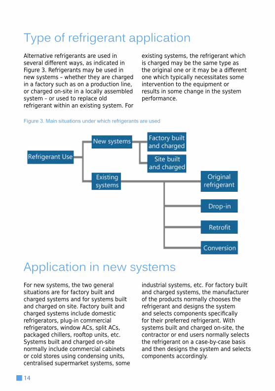
Type of refrigerant applicationAlternative refrigerants are used in several different ways, as indicated in Figure 3. Refrigerants may be used in new systems – whether they are charged in a factory such as on a production line, or charged on-site in a locally assembled system – or used to replace old refrigerant within an existing system. For
existing systems, the refrigerant which is charged may be the same type as the original one or it may be a different one which typically necessitates some intervention to the equipment or results in some change in the system performance.
Figure 3. Main situations under which refrigerants are used
Application in new systemsFor new systems, the two general situations are for factory built and charged systems and for systems built and charged on site. Factory built and charged systems include domestic refrigerators, plug-in commercial refrigerators, window ACs, split ACs, packaged chillers, rooftop units, etc. Systems built and charged on-site normally include commercial cabinets or cold stores using condensing units, centralised supermarket systems, some
industrial systems, etc. For factory built and charged systems, the manufacturer of the products normally chooses the refrigerant and designs the system and selects components specifically for their preferred refrigerant. With systems built and charged on-site, the contractor or end users normally selects the refrigerant on a case-by-case basis and then designs the system and selects components accordingly.

15
Figure 4: Charging equipment on a production line
© D
anie
l Col
bour
ne©
Dan
iel C
olbo
urne

16
Application in existing systems
3 Usually the term “drop-in” is used for this type of replacement. However, since there are no alternatives with identical thermophys-ical, safety and chemical properties as the existing refrigerant (e.g., HCFC-22) the term “drop in” is not entirely correct.
As the HCFC phase-out proceeds there is still a need to service the installed population of systems until the end of their useful lives. Changing the refrigerant in existing systems can be more complex and requires deeper consideration of the consequences.
When servicing these products the choice of refrigerant can fall into the following categories:
• Original refrigerant• Drop-in3
• Retrofit • Conversion (to flammable
refrigerant)
Since about 60 – 80% of refrigerant sales are for the servicing sector, the majority of refrigerant consumption is used for existing systems. HCFC consumption can be reduced by the use of alternative refrigerants in existing equipment. In the case of refrigerant replacement and retrofit in HCFC systems, the GWP of the new refrigerant should also be given consideration as many blends have a higher GWP.
With new refrigerants for existing systems, there are a number of criteria to target for a desirable choice of refrigerant; in summary these are:
• As close a volumetric refrigerating capacity over the range of normal operating evaporator and condenser temperatures;
• Does not lead to lower energy efficiency;
• Does not exceed the system design pressure at maximum condenser temperature;
• As close a match to the temperature glide, or negligible temperature glide if the original was a single component;
• Similar oil solubility and miscibility gap;
• Non-flammable;• Lower toxicity;• Commercial availability of
refrigerant (with reasonable cost)• Zero ODP, lower GWP and generally
no greater environmental impact
There are a number of other parameters that should be considered. However, in practical terms it is unlikely that any of the commercially available refrigerants can meet all of the above criteria and therefore some compromise should be anticipated.
Note that the quantity of the replacement refrigerant will nearly always be different from the original one.
In all cases, before changing from the original refrigerant it is recommended that the system manufacturer be consulted.

17
Original refrigerant
Using the existing refrigerant following a repair, one can follow normal practices using virgin, recycled or reclaimed refrigerant (i.e., typically HCFC-22). Therefore, implementing recovery and
reclaim programmes coupled with the availability of replacement and retrofit refrigerants could help reduce the demand for HCFC-22.
Figure 5: Charging HCFC-22 into an air-conditioning system
Drop-in
Drop-in represents refrigerant replacement only, where the HCFC is replaced with a blend, but without changing the lubricant used in the original equipment or any other system component. Refrigerants used for this activity are sometimes referred to as “service blends” or “drop-ins”. Such a change in refrigerant in most cases results in a lower capacity and/or efficiency, different operating pressures,
temperatures and compressor power compared to HCFC.
There are several refrigerants currently introduced to replace HCFC-22 for servicing, which attempt to mimic the performance of HCFC-22. However, they seldom perform as well as HCFC-22; having either lower capacity, efficiency or both.

Retrofit
Figure 6: Changing refrigerant in air-conditioning unit
Retrofit refers to not only changing the refrigerant, but also system components such as lubricant (although not always necessary), filter dryer (if required) and more extensive modifications which could include the replacement of the compressor, expansion device, and purging and flushing the system to remove all residual lubricant from the
system. Retrofitting can be substantially more costly than using existing refrigerant, replacing the refrigerant without additional changes or even unit replacement.
18
Conversion with flammable refrigerants4
Conversion is where the existing refrigerant is replaced with another without necessarily having to address the refrigeration circuit components and lubricant in the same way as retrofit, but because the replacement refrigerant is flammable, the external aspects of the
equipment, such as potential sources of ignition, have to be addressed. However, since this is a complex process and can lead to unforeseen safety risks, it is not normally recommended. Again, such a change in refrigerant can affect capacity and/or efficiency, operating pressures,
4 At a recent meeting of the Executive Committee, Decision 72/17 was agreed, which stated: “anyone engaging in retrofitting
HCFC-based refrigeration and air-conditioning equipment to flammable or toxic refrigerants and associated servicing, does so on
the understanding that they assume all associated responsibilities and risks” (www.multilateralfund.org/72/English/1/7247.pdf).
Essentially this implies that the bodies under the Montreal Protocol do not necessarily condone or will take responsibility for any
adverse consequences arising from the choice to use flammable refrigerants in equipment not intended for their use.

19
Figure 7: Servicing a rooftop system
temperatures, lubricity, etc., compared with HCFC.
This is occurring in some countries, whilst in others the practice is not legal. Although these refrigerants may provide capacity and efficiency close to that of HCFC-22, this practice can pose significant flammability safety hazards. In general, HCs are not recommended for use in systems that have not been
specifically designed appropriately. If HCs are being considered then the applicable safety standards and codes of practice should be strictly followed; the handbook for hydrocarbon safety (GIZ, 2010) and another specifically addressing such conversions (GIZ, 2011) are sources of information on the utilisation of these refrigerants (see Further Reading page 63).
Use in new refrigeration, air-conditioning and heat pump systems According to the different selection criteria and appropriate trade-off, the practical use of the HCFCs and various alternative refrigerants can be summarised. The table 2 indicates where a particular refrigerant is or potentially can be used.
It can be seen that in every common sector and sub-sector, alternative refrigerants with additional safety characteristics are already being applied (to some extent) or at least have the potential to be applied.

20
Sector/sub-sector
HC
FC-2
2
HFC
-32
HC
FC-1
23
HFC
-152
a
HC
-290
R-4
10A
R-4
44A
R-4
44B
R-4
45A
R-4
46A
R-4
47A
R-4
51A
R-4
51B
R45
4A
R45
4B
HC
-600
a
R-7
17
R-7
44
HFC
-123
4yf
HFC
-123
4ze(
E)
HC
-127
0
Domestic refrigeration
Refrigerators and freezer
P P P P C P P
Commercial refrigeration
Stand alone equipment C C P P P P C C P P C
Condensing units C P C C C P P P P P P P P C P C
Centralised systems C [C] [C] P [C] C
Transport refrigeration C P P P C P P P P P P P P C P P
Large size refrigeration C P C C P P P P P C C C
Air-conditioning and heat pumps
Small self contained C C C C P P P P P C
Mini-split (non-ducted) C C C C C P P P P P C
Multi-split C P C P P P P P
Split (ducted) C P C P P P P P CDucted split comm. & non-split
C P [C] [C] C P P P P P C [C]
Hot water heating HPs C C C C P P P P P P C C P P C
Space heating HPs C P C C C P P P P P P P P P C C P P C
Chillers
Positive displacement
C P C C C P P P P P P P P C C P C C
Centrifugal C P P PMobile air-conditioning
Cars P P P P P P C C PPublic transport C P C P P P P P P P P P C C
Table 2: Application of refrigerants by sector
Key:C indicates current use on a commercial-scale P indicates potential use in the future[ ] indicates that the substance is used in an alternative system

21
Consideration of system lifetimeIn order to ensure that products and installations are safe throughout the lifetime of equipment – both with regards to members of the public and workers, it is essential to address each stage in the equipment lifetime. The main stages in the equipment lifetime are shown in Figure 8.
To the left of Figure 8 are the key stages in the equipment lifetime, from conception of the product to the disposal of the equipment. In the centre column are examples of the personnel that are primarily concerned with working on those stages. To the right are examples of the types of activities those personnel are required to be competent at, in order to maintain a high level of safety. All the personnel involved need to be
aware of their responsibilities, and those in charge must make sure that the workers are informed and aware of those responsibilities. Furthermore, it is clear that the actions taken by personnel at any stage in the equipment life usually have consequences at the latter equipment stages.
In general, since the equipment spends most of its lifetime in ‘in-use – operation’ stage, this represents the period within which the safety implications are most prominent.

22
EQUIPMENT STAGES RELEVANT PERSONNEL EXAMPLE ACTIVITIES
productdevelopment
design
manufacture
storage anddistribution
installation
commissioning
technical managers development engineers
design engineers
production managerassembly line technicians
logistics department
installation technicians
commissioning engineer
•equipment design and development•conformity to regula-tions and standards•risk analysis concepts•product safety testing
•production and manufacture•sample testing
•storage of products and parts•transportation
•installation of equipment•refrigerant handling
•checking installation•functionnal testing
PROD
UCTI
ON
in-use
service
maintenance
service, maintenance, other field technicians
•service and maintenance practices•refrigerant handling•retrofitting and workshop conversionOP
ERAT
ION
decommissioning
disposal
service, maintenance, other field technicians
•decommissioning and disposal•refrigerant handling
END-
OF-L
IFE
Figure 8. Overview of the stages within the equipment lifetime, the key personnel and the subject groups that may be needed to execute the work

23
There are common activities within many of the stages, meaning that many of the people involved in such stages need to be familiar with the technical details from various sections. For example, people working in production, installation, servicing, maintenance and decommissioning all need to be aware of good refrigerant handling practices. Also, people involved with the design, installation, commissioning, servicing and maintenance all need to be familiar with the requirements of the safety standards, to some extent depending upon their duties. Thus, many of the issues are interrelated throughout all the stages of the equipment life.
In general, whilst an organisation is preparing material for and working on each of the stages within the equipment lifetime, the following issues should be kept in mind for the purposes of ensuring the necessary levels of safety:
• In order to assist those working at the various stages, it would be useful to provide staff with concise, easy to use manuals, guidance notes, etc, focussed on each part or for each key activity they are expected to carry out. Ensure that it is comprehensible and peer reviewed.
• Provide proper and thorough training to those involved, both theoretical and practical.
• Check other literature; manuals, handbooks, industry guidelines, manufacturers documentation, refrigerant suppliers information, etc, and the original regulations and safety standards to ensure that the correct information is used.5
• Develop a system for obtaining feedback from other stages and set up a scheme for information sharing. Using such feedback, for example, from field data, technicians, etc, on aspects such as leakage, equipment and component failures, problems with repairs, actual minor or major accidents, and so on. Utilising this information will greatly enhance the level of safety for the future.
Lastly, producing guidelines can never anticipate all the situations that may be encountered, or all the peculiarities of different types of equipment. Therefore it is important that individuals understand the logic behind the rules and in this way they can be adapted to new or unforeseen equipment and situations.
5 Refer to Further Reading, page 63

24
Introduction to hazards
Safe Use ofRefrigerants3
All refrigerants pose a number of safety implications:
• Asphyxiation, where displacement of oxygen causes suffocation
• Freeze burn, where cold refrigerant on the skin causes frostbite
• Toxicity effects – acute (e.g., anaesthesia, cardiac sensitisation) and chronic (e.g., liver damage)
• Flammability and explosion, where the refrigerant rapidly combusts when ignited
• Pressure (release), where a shock wave occurs from a rapid release of gas
The risk posed by refrigerants can be considered with regards to primary and secondary consequences, as shown in Figure 9. Essentially following a release of refrigerant, a sequence of events can
follow that ultimately can lead to some form of damage to persons and property. Depending upon the type of substance, the conditions and environment within which it is released can result in a variety of different consequences.
With the introduction and potentially wide use of refrigerants that are flammable, have higher toxicity and/or operate at notably higher pressures than the ordinary refrigerants, consideration of safety matters becomes more important. Accordingly, more attention must be paid to the requirements of safety standards, regulations and good working practices that directly relate to refrigerants that exhibit these characteristics.

25
Figure 9. Overview of the various hazards associated with a release of refrigerant
Safety classification of refrigerantsThe most widely used classification of substances is under the UN system for dangerous goods. Substances receive an alphanumeric designation, related to its state and other safety hazards. Depending upon a substance’s
classification, there are sets of generic rules which regard handling, labelling and other matters. An illustration of the system for selected refrigerants is shown in Table 3.
Table 3. Classification examples for UN system for dangerous substances
Number for state State Letter(s) for
hazard Hazard Examples
2 Liquefied gas (under pressure)
A Non-flammable HCFC-22, R-744
A Flammable HC-290, HFC-32
TC Toxic and corrosive R-717

26
6 International Organization for Standardization (ISO) 817, Refrigerants – designation and safety classification
Within the refrigeration industry, a different classification scheme is applied, where most refrigerants are assigned a safety classification, which is a function of toxicity and flammability. The classification scheme is adopted by standards such as ISO 817.6
The toxicity classification is based on whether toxicity has or has not been identified at a certain concentration; there are two toxicity classes:
• Class A: no chronic toxicity effects have been observed below 400 ppm
• Class B: chronic toxicity effects have been observed below 400 ppm
The flammability classification depends upon whether or not the substances can be ignited in standardised tests, and if so, what the lower flammability limit (LFL) is and what the heat of combustion is. There are now four flammability classes (according to ISO 817):
• Class 1: do not show flame propagation when tested in air at
60°C and standard atmospheric pressure
• Class 2L: as Class 2 but with a laminar flame speed of less than 0.10 m/s
• Class 2: exhibit flame propagation when tested at 60°C and atmospheric pressure, but have a LFL higher than 3.5% by volume, and have a heat of combustion of less than 19,000 kJ/kg
• Class 3: exhibit flame propagation when tested at 60°C and atmospheric pressure, but have an LFL at or less than 3.5% by volume, or have a heat of combustion
that is equal to or greater than 19,000 kJ/kg
Typically, a “higher” classification – that is toxicity Class B instead of Class A, and flammability Class 3 instead of Class 1 – means that the refrigerating system has more onerous design requirements associated with it, in order to handle the higher risk presented by the refrigerant (Figure 10).
© E
.Cla
rk
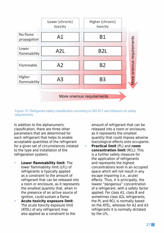
Figure 10. Refrigerant safety classification according to ISO 817 and influence on safety requirements
27
In addition to the alphanumeric classification, there are three other parameters that are determined for each refrigerant that helps to enable acceptable quantities of the refrigerant for a given set of circumstances (related to the type and installation of the refrigeration system).
• Lower flammability limit: The lower flammability limit (LFL) of refrigerants is typically applied as a constraint to the amount of refrigerant that can be released into a room or enclosure, as it represents the smallest quantity that, when in the presence of an active source of ignition, could sustain a flame.
• Acute toxicity exposure limit: The acute toxicity exposure limit (ATEL) of any refrigerant may also applied as a constraint to the
amount of refrigerant that can be released into a room or enclosure, as it represents the smallest quantity that could impose adverse toxicological effects onto occupants.
• Practical limit (PL) and room concentration limit (RCL): This is a further safety measure for the application of refrigerants and represents the highest concentrations level in an occupied space which will not result in any escape impairing (i.e., acute) effects. Thus, it is principally, the lowest “dangerous” concentration of a refrigerant, with a safety factor applied. For class A1, class B and sometimes class A2L refrigerants, the PL and RCL is normally based on the ATEL, whereas for A2 and A3 refrigerants it is normally dictated by the LFL.

28
When applying a particular refrigerant, the characteristics of the system within which it is used and the characteristics of the local environment dictate the manner in which it is applied and also the quantities of refrigerant that are allowed, according to the common safety standards (e.g., EN 3787, ISO 51498). There are different arrangements for refrigeration systems, locations within which parts of the system are present and types of occupancy.
The main system arrangements can be broadly divided into two types: “direct” and “indirect” (with respect to the “target” of the cooling or heating). A direct system is where the refrigerant-containing parts are located in the space to be cooled or heated (whether it is a cold room, a display cabinet or an air conditioned room) and the refrigerant from a leak could flow unobstructed into the space to be cooled or heated. An
indirect system is one that uses some heat transfer fluid (HTF) such as water, brine or glycol, to transfer heat between the space to be cooled and the primary refrigerant circuit; in this regard, if there is a leak of refrigerant then it is unlikely to enter the cooled or heated space and the risk is typically lower.
Figure 11 shows some examples of direct systems. Case (a) could be a split air-conditioner or a cold store, case (b) could be a refrigerated display case connected to an external condensing unit, case (c) could be a ducted air-conditioning system and case (d) could be a plug-in storage cabinet or a portable air-conditioner. In all cases, there is refrigerant piping and/or refrigerant-containing parts that could directly leak refrigerant into the occupied space.
Classification of refrigeration systems, locations and occupancies
7 EN 378, Refrigeration systems and heat pumps – Safety and environmental requirements8 ISO 5149, Refrigerating systems and heat pumps — Safety and environmental requirements
Figure 11. Examples of direct systems
(a)
(b)

29
Figure 11. (continued) Examples of direct systems
Figure 12 gives examples of indirect systems. Case (e) could be a refrigerated warehouse using a brine or a chilled water air-conditioning system and case (f) could be an air-conditioning system using a chilled water coil in a central air handling unit. With both cases, no refrigerant piping or other parts of the
circuit are directly within the occupied space and so a leak of refrigerant would be highly unlikely to be present in those occupied spaces.
Figure 12. Examples of indirect systems
(c)
(d)
(e)
(f)

30
The “occupancy” refers to the intended use of the space and degree of knowledge of safety procedures by those that are present. As such, occupancies are normally categorised into four types:
• Public spaces (with “general” occupancy): ‘category a’ – such as retail areas in shops and public parts of auditoria
• Private spaces (with “supervised” occupancy): ‘category b’ – such as offices
• Restricted access (with “authorised” occupancy): ‘category c’ – such as workshops, cold stores, etc
• Unoccupied spaces – such as machinery rooms and authorised access-only spaces
Since the risk to persons is greater in occupancy a spaces, where there are broadly uncontrolled numbers, most of whom have no idea about safety procedures in the event of an
emergency, requirements tend to be more stringent. Whereas for restricted access spaces with (typically) only a small number of authorised persons that have a high level of knowledge of safety procedures, the requirements are less severe.
Figure 13 provides an illustration of these concepts. Here, “more severe” requirements refer to the obligations on the design and construction of the refrigeration equipment, which may include:
• A limit on the amount of refrigerant that is permitted in the system
• The number of safety devices (such as pressure relief valves, pressure switches and temperature limiters) to be added to the system
• The use of additional features such as gas detection and mechanical ventilation
Figure 13. Representation of the severity of safety requirements as a function of occupancy and system type

31
Regulations, safety standards and guidelines9
9 For more information, refer to http://www.unep.fr/ozonaction/information/mmcfiles/7679-e-International_Standards_in_RAC.pdf
Depending upon the country and the circumstances, there are a large number of regulations, safety standards, codes of practice and industry guidelines to help with the safe application of flammable, higher toxicity and higher pressure refrigerants. The Further Reading section (page 63) provides a more comprehensive list of various publications that are available.
National and regional regulations represent the overarching authority in terms of special considerations for the use, design and installation of equipment. Given the diversity amongst Article 5 countries, it is not possible to generalise particular regulations. However, it is common to have
regulations covering these topics in most regions:
• Safe use and application of flammable substances
• Safe handling of flammable substances
• Safe design and use of equipment under elevated pressures
• Characterisation and controls of substances that pose toxicity risks
Typically such regulations provide a framework for evaluating hazards and mitigating risk and only with basic provision of practical requirements with a demand that things must be “safe”; such a formulation therefore allows for implementation of new substances and
32
applications and allows for technological development where needed. Since almost all refrigerants operate under pressure and have some extent of toxic effects and many of them are also flammable, it is to be expected that most of the previously mentioned types of regulations need to be considered.
At the next level, safety standards (and industry codes of practice) are developed in order to provide more practical interpretation of the guidance from regulations. Sometimes these are developed for specific types of equipment or applications (so-called
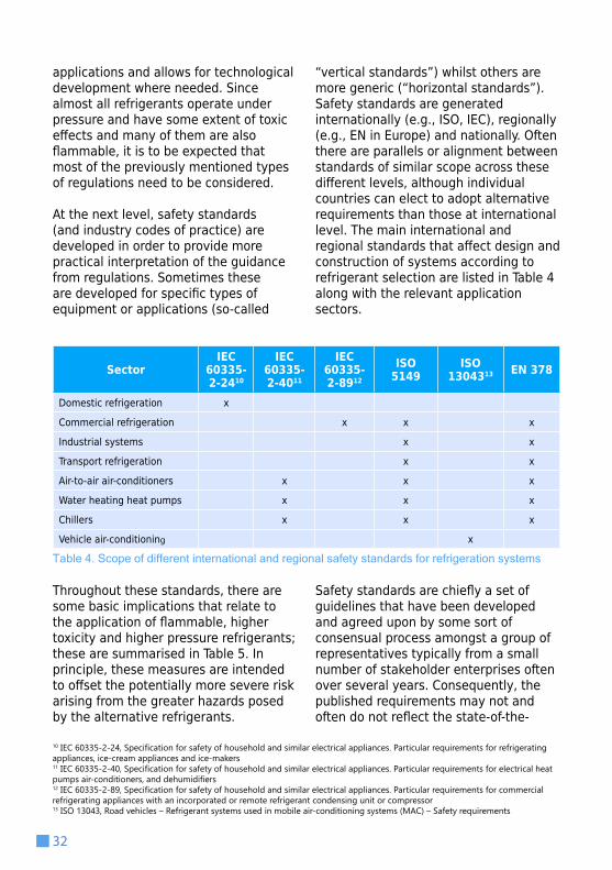
“vertical standards”) whilst others are more generic (“horizontal standards”). Safety standards are generated internationally (e.g., ISO, IEC), regionally (e.g., EN in Europe) and nationally. Often there are parallels or alignment between standards of similar scope across these different levels, although individual countries can elect to adopt alternative requirements than those at international level. The main international and regional standards that affect design and construction of systems according to refrigerant selection are listed in Table 4 along with the relevant application sectors.
SectorIEC
60335-2-2410
IEC 60335-2-4011
IEC 60335-2-8912
ISO 5149
ISO 1304313 EN 378
Domestic refrigeration x
Commercial refrigeration x x x
Industrial systems x x
Transport refrigeration x x
Air-to-air air-conditioners x x x
Water heating heat pumps x x x
Chillers x x x
Vehicle air-conditioning x
Table 4. Scope of different international and regional safety standards for refrigeration systems
10 IEC 60335-2-24, Specification for safety of household and similar electrical appliances. Particular requirements for refrigerating appliances, ice-cream appliances and ice-makers 11 IEC 60335-2-40, Specification for safety of household and similar electrical appliances. Particular requirements for electrical heat pumps air-conditioners, and dehumidifiers 12 IEC 60335-2-89, Specification for safety of household and similar electrical appliances. Particular requirements for commercial refrigerating appliances with an incorporated or remote refrigerant condensing unit or compressor13 ISO 13043, Road vehicles – Refrigerant systems used in mobile air-conditioning systems (MAC) – Safety requirements
Throughout these standards, there are some basic implications that relate to the application of flammable, higher toxicity and higher pressure refrigerants; these are summarised in Table 5. In principle, these measures are intended to offset the potentially more severe risk arising from the greater hazards posed by the alternative refrigerants.
Safety standards are chiefly a set of guidelines that have been developed and agreed upon by some sort of consensual process amongst a group of representatives typically from a small number of stakeholder enterprises often over several years. Consequently, the published requirements may not and often do not reflect the state-of-the-

Table 5. Main measures to be considered for substances with greater pressure, toxicity and/or flammability
33
Greater flammability Greater toxicity Greater pressure
• Stricter limits on the quantity of refrigerant in occupied spaces• Use of gas detection, alarms and emergency ventilation• Prohibition of items that could act as sources of ignition• Warnings/signage
• Stricter limits on the quantity of refrigerant in occupied spaces• Limited use in more densely populated areas• Use of gas detection, alarms and emergency ventilation• Provision of personal protective equipment
• Thicker materials/higher pressure rating for pipes and components• Additional use of pressure relief devices and/or pressure limiting devices• Higher competencies for work-ers involved in construction of components and assemblies
art in technology and can also favour certain technologies over others, as according to the enterprises that participate in the process. Similarly, standards are continually evolving and requirements also tend to change over time; despite this, standards are seldom without oversights. For these reasons, stakeholders that utilise such standards must give close consideration to the text and meaning of these standards and where necessary use diligence in adopting suitable measures.
Often industry bodies, such as technical institutes and associations develop publications such as codes of practice
and technical guidelines on safety matters. These typically provide further practical interpretation of the requirements of regulations and to some extent safety standards. These are particularly useful when the formal sources contain errors (which may take many years to correct due to bureaucratic procedures) or ambiguities that need explicit interpretation for industry practitioners. Furthermore, the information can also be tailored for local conditions and practices and also provide alternative routes to achieving the level of safety required by regulations but not otherwise offered by safety standards.

Important considerations for various activitiesSince the various alternative refrigerants pose additional safety hazards compared to the ordinary refrigerants, it is essential that they are handled differently in some respects, or the same with additional precautions. Table 6 lists a selection of some of these refrigerants and observation of some of their respective safety parameters – such as safety class, saturation pressure, LFL, ATEL and PL provide an introduction to the basic difference compared to HCFC-22.
It is essential that these “new” characteristics are taken into consideration throughout the entire lifetime of the use of the refrigerant.
Depending upon the stage at which refrigeration equipment is, there are various activities that may be considered to be of particular importance when working with certain alternative refrigerants. Table 7 provides a summary of some of the more important activities that should be planned and carried out carefully in order to minimise the additional risk associated with switching to a flammable, higher toxicity or higher pressure refrigerant.
34
Detailed Considerations for Refrigerants
4

Table 6: Safety data for selected refrigerants16
35
Refrigerant Safety class (ISO 817)
Saturation pressure at 25°C (bar,
abs)
Lower flammability limit (LFL) in % by volume
in air (and g/m3)
Acute toxicity
exposure limit (ATEL) in % by volume in air (and g/m3)
Practical limit (PL) in % by volume in air (and
g/m3)
HCFC-22 A1 10.4 None 5.9% (209) 5.9% (209)
HFC-32 A2L 16.9 14.4% (306) 22% (468) 2.9% (61)
HCFC-123 B1 0.9 None 0.9% (57) 0.9% (57)
HFC-134a A1 6.7 None 5.0% (210) (250)
HFC-152a A2 6.0 4.8% (130) 5.0% (140) 1.0% (27)
HC-290 A3 9.5 2.1% (38) 5% (90) 0.4% (8)
R-404A A1 12.5 None 13.0% (520) 13.0% (520)
R-407C A1 11.9 None 8.8% (310) 8.2% (290)
R-410A A1 16.6 None 14.8% (440) 14.2% (420)
R-444A* A2L 7.1 7% (290) 6% (270) 1.4% (60)
R-444B* A2L 10.6 7% (180) 8% (200) 1.4% (40)
R-445A* A2L 7.4 8% (340) 6% (250) 1.5% (70)
R-446A* A2L 13.7 8% (180) 3% (60) 1.6% (40)
R-447A* A2L 13.8 9% (220) 11% (260) 1.9% (50)
R-451A* A2L 6.8 7% (320) 9% (420) 1.4% (60)
R-451B* A2L 6.8 7% (320) 9% (410) 1.4% (60)
R454A* A2L 6.8 8% (290) 12% (470) 1.5% (60)
R454B* A2L 12.8 10% (300) 16% (470) 2.0% (60)
HC-600a A3 3.5 1.8% (43) 2.9% (69) 0.4% (9)
R-717 B2L 10.0 16.7% (116) 0.03% (0.2) 0.03% (0.2)
R-744 A1 64.3 None 4.0% (72) 4.0% (72)
HFC-1234yf A2L 6.8 6.2% (289) 10% (466) 1.2% (58)
HFC-1234ze(E) A2L 5.0 6.5% (303) 5.9% (275) 1.3% (61)
HC-1270 A3 11.5 2.7% (46) 0.1% (2) 0.5% (9)
* Data for these new mixtures is not publically available so LFL, ATEL and PL are approximated and rounded
14 Useful standards include EN 15834, Refrigerating systems and heat pumps — Qualification of tightness of components and joints15 EN 13313: 2008 – Refrigeration Systems and Heat Pumps. Competence of Personnel16 Refer to the Appendix (page 64) which provides safety characteristics for most commercially available refrigerants.
Of particular importance are aspects related to risk assessment, design requirements for systems, leak tightness of systems14, topics for training and tools and equipment normally used by technicians; these are addressed in more
detail henceforth. Standards such as EN 1331315 are helpful for identifying the competence criteria for the training of persons carrying out different types of tasks.

36
‘‘It is essential that alternative refrigerants are handled with additional precautions.’’
© E
.Cla
rk

Table 7. Considerations for main activities for all flammable, higher toxicity and higher pressure refrigerants
37
Activity Important considerations
Product development• Awareness of the need for features to mitigate flammability/toxicity/pressure risk• Flammability/toxicity/high pressure risk assessment• Suitable safety testing
Design• Adherence to regulations, standards (avoiding flammable releases, leakage, ignition sources) • Third party approvals
Manufacturing
• Suitable storage of refrigerant, charging equipment, leak detection, factory safety systems• Availability of proper parts and components (e.g., safe electrical equipment)• Workers are suitably trained
Storage and distribution• Suitability of transport is properly assessed• Warehousing is properly assessed• Proper markings/warnings for packaging
Installation• Technicians in possession of proper refrigerant handling tools and equipment• Technicians are suitably trained• Safe work procedures are provided and followed
Commissioning
• Engineers are suitably trained• Leak tightness and strength pressure checking• Checking safety systems (gas detectors, gas detection, emergency ventila-tion and alarms)
In-use
• For large systems, gas detection, emergency ventilation and alarms are functional• For all systems, product development, design and installation should be adequate for inherent safety
Service• Technicians are suitably trained• Technicians in possession of proper refrigerant handling tools and equipment• Safe work procedures are provided and followed
Maintenance• Technicians are suitably trained• Technicians in possession of proper refrigerant handling tools and equipment• Safe work procedures are provided and followed
Decommissioning
• Technicians are suitably trained• Technicians in possession of proper refrigerant handling tools and equipment• Safe work procedures are provided and followed• Proper and safe venting procedures, where appropriate
Disposal • Disposal facility is aware of residual potentially flammable gas• Proper markings/warnings for packaging

Safety issues related to flammable refrigerants There are a number of flammable refrigerants – some old and some recently developed. Table 6 (page 35) lists some of the basic safety characteristics of the flammable refrigerants that are currently used and some that are being studied in anticipation of their commercialisation. Although there are many flammable refrigerants the extent of their flammability varies quite widely; it can be seen that some substances have relatively low LFLs (Lower flammability
limit) (e.g., HC-290 with 38 g per m3) whilst others have significantly greater LFL (e.g., HFC-1234yf with 289 g per m3). There are other flammability characteristics such as minimum ignition energy, heat of combustion and burning speed that have an impact of the ease to which a substance can be ignited and the severity of the consequence following ignition; these are all broadly proportionate to the LFL.
38
General risk assessment
With all flammable refrigerants, the risk arises with the possible ignition of a flammable concentration. Ignition is caused by an unprotected source of ignition – this could be an electric spark, a naked flame, a very hot surface or some other event that creates sufficient energy. Ignition may occur wherever the refrigerant has leaked and mixed with air in the correction proportions, i.e., between the lower and upper flammability limits. Depending upon the architecture of the equipment, this could occur within the refrigerated space, within equipment housing, within other spaces that piping or parts are present or in the open air. The initial consequences can include pressure rise (“overpressure”), thermal radiation
and formation of toxic decomposition products (e.g., from the flammable HFCs). Depending upon the local conditions, subsequent consequences may be physical damage to property and persons, creation of a secondary fire and toxic effects of the decomposition products on persons. Figure 14 provides the basic steps for a flammability risk assessment. Note that it is not only sufficient to assess the risk but also to identify and introduce risk mitigation measures in order to avoid or minimise the likelihood and consequences of unintended outcomes.

Figure 14. Basic steps for flammability risk assessment
39
Refrigeration system design requirements
For flammable refrigerants, appropriate design requirements – that are over and above what would normally be required for ordinary refrigerants – can be found in regulations, standards, codes of practice and industry guidelines. The main issues described in these sources to be addressed, include:
• Limiting the quantity of refrigerant to an amount that is unlikely to be ignited (i.e., refrigerant charge limits)
• Designing the system and components for smaller refrigerant charge amounts
• Not installing equipment in vulnerable locations (i.e., where there are an excess of potential sources of ignition)
• Ensuring systems have a high level of leak tightness.
• Constructing the system so that there are no potential sources of ignition that could ignite a refrigerant leak (e.g., no sparking components where a leak of refrigerant could accumulate)
• More frequent use of gas detection and ventilation systems to assist with dispersing any leak of refrigerant

40
• Applying the necessary warnings to accessible parts of the system to ensure that technicians are aware of the hazard (e.g., flammable gas stickers near charging points)
• Including the necessary information relating to flammability in installation and operating documentation
Table 8 provides some example charge size limits based on selected conditions for various flammable refrigerants (noting that different standards and guidelines tend to have different limits). It can be seen that refrigerants with a higher LFL are permitted larger quantities (per refrigerant circuit) than those with lower LFL. In such cases where a greater refrigerant charge is desired, additional features can be applied to the design of the system so that the amount of refrigerant that
would be released or the developed concentration in the event of a leak can be limited. For example, the use of shut-off valves within the circuit, which are initiated by gas detectors or operating parameters, thereby preventing all the refrigerant leaking out. Similarly gas detectors or other parameters can be used to initiate airflow to dilute the refrigerant in the event of a leak such that the concentration cannot reach the LFL. Also, larger systems can be divided into smaller systems with smaller refrigerant charges. By adopting such measures, these flammable refrigerants can be applied more widely. For systems installed outside in the open air or in machinery rooms, there are normally no such limitations. Standards such as EN 1127-117 are useful for assisting with the design considerations of systems use flammable refrigerants.
17 EN 1127-1, Explosive atmospheres – explosion prevention and protection. Basic concepts and methodology
Key topics for training
As discussed previously, training is necessary for all those involved at all stages throughout the life of the equipment; amongst factory workers, system design engineers and field technicians, a number of topics are generally necessary (in addition to those for general safety of all refrigerants). Table 9 provides an indicative list of the general topics that are normally required for persons involved in applying and handling flammable refrigerants. Generally the basic principles are
necessary for all involved, whereas the other topics may be more relevant to those involved in the development and design of equipment or refrigerant handling activities during installation, service, maintenance, etc.

41
Refrigerant Class Refrigerant
Example design test pressure a (bar, abs)
Allowable charge
in 15 m2 occupied
space (comfort) b
(kg)
Allowable charge
in 15 m2 occupied
space (general) c
(kg)
Max. charge in occupied
space (occupancy A / B) (kg)
Max charge in
open air or machinery
room
Max charge for a
ventilated enclosure
(kg)
A1
HCFC-22 32 11.3 11.3
PL×RV d no limit PL×RV d
HFC-134a 22 9.4 9.4
R-404A 38 19.5 19.5
R-407C 36 11.6 11.6
R-410A 50 16.5 16.5
R-744 129 f 3.8 3.8
A2L
HFC-32 51 1.3 – 4.9 2.3 12 (60 e)
no limit
60
R-444A 22 1.2 – 4.6 2.2 11 (57 e) 57
R-444B 32 0.7 – 2.5 1.4 7 (36 e) 36
R-445A 22 1.5 – 5.5 2.5 13 (66 e) 66
R-446A 41 0.7 – 2.2 1.4 7 (35 e) 35
R-447A 42 0.9 – 3.3 1.7 9 (43 e) 43
R-451A 21 1.4 – 5.1 2.4 12 (62 e) 62
R-451B 21 1.4 – 5.1 2.4 12 (62 e) 62
R-454A 29 1.2 – 4.6 2.2 11 (57 e) 57
R-454B 39 1.3 – 4.7 2.2 12 (58 e) 58
HFC-1234yf 21 1.2 – 4.5 2.2 11 (56 e) 56
HFC-1234ze(E) 17 1.3-4.8 2.3 12 (59 e) 59
A2 HFC-152a 20 0.5 – 1.7 1.0 3.4 no limit 17
A3 gHC-290 28 0.1 – 0.4 0.3 1.5 / 2.5
no limit
4.9
HC-600a 11 0.1 – 0.4 0.3 1.5 / 2.5 5.6
HC-1270 33 0.1 – 0.4 0.3 1.5 / 2.5 6.0
B1 HCFC-123 4 2.1 2.1 PL×RV no limit PL×RV
B2L R-717 34 0.01 0.01 4.5 no limit 23
Table 8. Example test pressures and charge limits for selected refrigerants and occupancies for ISO 5149
PL=Practical limit; RV=Room volumea Assuming 46°C ambient, 10 K condenser temperature difference, individual test (1.43 times the maximum condenser pressure)b Depending upon installation conditions c 2.5 m high roomd For systems with multiple indoor heat exchangers a higher charge may be allowed depending on circumstances. e For systems with multiple indoor heat exchangersf Since condition is supercritical (i.e., in a transcritical process), pressure based on 90 bar design pressure for gas coolerg HC refrigerants have much lower densities so 2 – 3 times greater refrigerating capacity can be achieved with the same charge of refrigerant Note: Allowable and maximum charges are per individual refrigerant circuit and there is no limit on the number of separate circuits in a roomNote: The values provided within this table are indicative and determination of refrigerant charge size limits for particular types of systems and installation locations requires the use of the standard and the values within this table should not be taken as a substitute

Topics
Flam
mab
le
Hig
her
toxi
city
Hig
her
pres
sure
Basic principles• How to carry out flammability risk assessment for systems and installations X
• How to carry out toxicity risk assessment for systems and installations X
• How to carry out elevated pressure risk assessment for systems and installations X
• Awareness of material safety data sheets (MSDS) X X X
• Flammability characteristics (“fire triangle”, LFL, ignition energy, heat of combustion, etc) X
• Toxicity characteristics (short term, long term, physiological effects, etc) X
• Relevant safety standards and regulations that relate to equipment using flammable, higher toxicity and higher pressure gases X X X
• Differences in refrigerant density compared to ordinary refrigerants and the implications on charge size and cylinder filling X
• Differences in refrigerant pressure compared to ordinary refrigerants and the implications on system design pressure and size and cylinder pressure ratings
X
• Behaviour of a leak of refrigerant under different circumstances, i.e., the flow of denser-(or lighter-) than-air gas in closed rooms, enclosures, the out-side in still or windy conditions and the effect of ventilation
X X
System design and construction• Classifications within refrigeration safety standard – flammability, toxicity, occupancies, locations, system types X X X
• Requirements of safety standards – determination of charge size limits (or minimum room sizes), need for safety devices (such as pressure limiters, pressure relief, etc), gas detection, ventilation, etc
X X X
• Sources of ignition; types of ignition sources, spark energies, temperature effects, etc X
• Need for and types of protection appropriate for potential sources of ignition X
• Importance of leak minimisation and methods for avoiding leakage X X X
• Information requirements such as equipment marking, labelling and signage X X X
(continued...)
Table 9. Key topics for training (not exhaustive)
42

43
Table 9. (continued) Key topics for training (not exhaustive)
Topics
Flam
mab
le
Hig
her
toxi
city
Hig
her
pres
sure
Working practices• How to carry out a risk assessment for creating and maintaining a safe working area and for carrying out work on a system containing flammable refrigerants
X
• How to carry out a risk assessment for creating and maintaining a safe working area and for carrying out work on a system containing higher toxicity refrigerants
X
• How to carry out a risk assessment for creating and maintaining a safe working area and for carrying out work on a system containing higher pres-sure refrigerants
X
• Selection and use of appropriate tools, equipment and personal protective equipment (PPE) when handling flammable, higher toxicity or higher pressure refrigerants
X X X
• Appropriate use of fire extinguishers X
• Standard procedures for safe charging, recovery, evacuation, venting, etc X X X
• Emergency response procedures, such as in the event of a major release or a fire or carrying out first aid X X X
• Provision of relevant information for data-plates, equipment documentation and owners/operators X X
• Selection of appropriate ‘like for like’ replacement components for electrical devices, electrical enclosures, compressors, etc., and maintaining the integrity of sealed electrical enclosures
X
• Presence and absence of odorant X
• Restriction on relocation of existing systems/equipment X X X
Service tools and equipment
For technicians and engineers that are working directly with flammable refrigerants, it is essential that workers have available and use the appropriate tools and equipment. Whilst it is often the case that certain tools and equipment are equally applicable to
most refrigerants, there are some that may ordinarily present an ignition risk. The most relevant tools and equipment are discussed in Table 10.

Figure 19. Refrigerant gas detectors for hydrocarbon (HC) refrigerants
© Bacharach Inc
Figure 17. Electronic manifold gauge set that can be used with flammable refrigerants, R-717 and high pressure refrigerants (up to 50 bar)
© Mastercool
Figure 15. Refrigerant recovery machines for HCs (left) and all flammable refrigerants except R-717 (right)
© cm-green
© RDA-eng.com
Figure 16. Ex-type mechanical fan using used for ventilating area when handling flammable refrigerants
© RDA-eng.com
Figure 18. Flammable gas warning sign that must be on flammable refrigerant recovery cylinders

45
Table 10. Considerations for tools and equipment for use with flammable refrigerants
Item Remarks
Gas detectors Should be electronic and intended for use with flammable gases and the refrigerant intended (Figure 19).
Balance/scales If electronic, should be suitable for use in an area where flammable refrigerant may be present, as confirmed by the manufacturer.
Manifold/gauge/hose setMaterials should be compatible, be able to withstand the maximum pressure and, if electronic, be suitable for use in the presence of flam-mable refrigerant (Figure 17).
Vacuum gauge If electronic, be suitable for use in the presence of flammable refriger-ant, as confirmed by the manufacturer.
Vacuum pumpShould be suitable for use with flammable gases (e.g., not with a brushed motor) or arranged so that it can be switched on/off in a loca-tion where a release of flammable refrigerant cannot reach.
Refrigerant cylinder adapters Ensure that the correct type of cylinder adapter is present to enable safe removal of refrigerant from the cylinder
Recovery cylinderMust be rated for the maximum pressure of the refrigerant being used and have the appropriate flammable gas warnings, also proper refriger-ant cylinder handling rules must be adhered to (Figure 18, Figure 28)
Refrigerant recovery machineMust be suitable for use with the type of refrigerant under consider-ation and also be designed appropriately for flammable refrigerants (Figure 15)
Venting hose
Due to the negligible environmental impact of direct releases for certain flammable refrigerants, specifically hydrocarbons, venting is sometimes practiced instead of recovering (generally for small refrigerant charges); in this case, a venting hose with sufficient length to allow venting directly to a safe place in the open air is necessary.
Mechanical ventilationWhen working with larger charges of refrigerant, it can be beneficial to use a safe mechanical ventilation unit to help dilute refrigerant that has been accidentally released
Personal protective equipment (PPE)
Normally standard items such as goggles, gloves, fire extinguisher (Figure 29, Figure 30)

46
Safety issues related to higher toxicity refrigerants As seen in Table 6, there is primarily one alternative refrigerant that is of higher toxicity, ammonia (R-717); as such this is the only refrigerant discussed in this section. The table lists some of the basic
safety characteristics, which shows that it is flammable as well as being higher toxicity. Another important consideration for R-717 is its corrosivity and its affinity for moisture.
General risk assessment
With higher toxicity refrigerants and specifically R-717, the primary hazard is the inhalation of leaked refrigerant by persons. Other hazards, albeit less common include direct contact with liquid refrigerant and possible ignition of a flammable concentration. Excessive exposure to a toxic concentration may arise due to an accidental release of refrigerant within an enclosed space – or even an open space if the release is of sufficient magnitude – and the occupants are not in immediate possession of the appropriate Personal Protective Equipment (PPE). Particularly with R-717, adverse reactions can occur even at extremely low concentrations (in the order of tens or hundreds of parts
per million in air). The consequences of inhalation can include irritation of eyes and nose with a sore throat, cough, chest tightness, inflammation, lacrimation, photophobia, headache and confusion and eventual fatality. The consequence of direct contact to the skin exposure may result in deep burns whereas inhalation may result in burns to the mouth and throat. Figure 18 provides the basic steps for a risk assessment for higher toxicity substances. Note that it is not only sufficient to assess the risk but also to identify and introduce risk mitigation measures in order to avoid or minimise the likelihood and consequences of unintended outcomes.

47
Figure 20. Basic steps for toxicity risk assessment
Refrigeration system design requirements
For higher toxicity refrigerants, appropriate design requirements – that are over and above what would normally be required for ordinary refrigerants– can be found in regulations, standards, codes of practice and industry guidelines. The main issues described in these sources to be addressed, include:
• Limiting the quantity of refrigerant to an amount that is unlikely to pose a toxicity risk (i.e., refrigerant charge limits)
• Designing the system and components for smaller refrigerant charge amounts
• Not installing equipment in vulnerable locations (i.e., where there are large groups of uncontrolled occupants)
• Ensuring systems have a high level of leak tightness.
• More frequent use of gas detection and ventilation systems to assist with dispersing any leak of refrigerant
• Provision of specialist personal protective equipment (PPE), such as respirators, suitable clothing and washing facilities.
• Applying the necessary warnings to accessible parts of the system to
48
ensure that technicians are aware of the hazard (e.g., warning signs near charging points)
• Including the necessary information relating to toxicity effects in installation and operating documentation
Table 8 (page 41) provides some example charge size limits based on selected conditions for R-717 (noting that different standards and guidelines tend to have different limits) and HCFC-123. It can be seen that
particularly with R-717, because of its very low acute toxicity exposure limit (ATEL), the permitted quantities of refrigerant (per refrigerant circuit) are extremely small. Depending upon the occupancy, location and type of system, larger quantities are allowed and furthermore, additional features can be applied to the design of the system so that the amount of refrigerant that would be released is limited. For systems installed outside or in machinery rooms, there are normally no such limitations.
Key topics for training
As discussed previously, training is necessary for all those involved at all stages throughout the life of the equipment; amongst factory workers, system design engineers and field technicians, a number of topics are generally necessary (in addition to those for general safety of all refrigerants). Table 9 (page 42) provides an indicative list of the general topics that are
normally required for persons involved in applying and handling higher toxicity refrigerants. Generally the basic principles are necessary for all learners, whereas the other topics may be more relevant to those involved in the development and design of equipment or refrigerant handling activities during installation, service, maintenance, etc.
Service tools and equipment
For technicians and engineers that are working directly with higher toxicity refrigerants, it is essential that workers have available and use the appropriate tools and equipment. Whilst it is often the case that certain tools and equipment are equally applicable to most refrigerants, there are some that
may ordinarily compromise safety. The most relevant tools and equipment are discussed in Table 11.

49
Figure 21. Refrigerant gas detector for ammonia (R-717)
© testolimited.com
Figure 22. R-717 recovery pump set
© Howe Corporation - Chicago, Illinois USA
Figure 23. Example of respiratory equipment
Figure 24. Example of protective suit for R-717
© R
olf H
ühre
n
© R
olf H
ühre
n

50
Table 11. Considerations for tools and equipment for use with ammonia (R-717)
Item Remarks
Gas detectors Should be electronic and intended for use with R-717 (Figure 21).
Manifold/gauge/hose setMaterials must be compatible with R-717, be able to withstand the maximum pressure and, if electronic, be suitable for the characteristics of R-717 (Figure 17).
Vacuum gauge Materials must be compatible with R-717.
Vacuum pump Should be suitable for the characteristics of R-717.
Refrigerant cylinder adapters Ensure that the correct type of cylinder adapter is present to enable safe removal of refrigerant from the cylinder
Recovery cylinderMust be rated for the maximum pressure of R-717, have the appropriate warnings and be of a material that is compatible with R-717. Also proper refrigerant cylinder handling rules must be adhered to (Figure 28, Figure 31)
Refrigerant recovery machine Must be suitable for use with R-717 (Figure 22)
Personal protective equipment (PPE)
Further to normal PPE, depending upon the quantity of refrigerant in-volved, special respiratory protection (canister type self-contained respi-rators or breathing equipment) shall be provided. In addition, protective clothing including face-shield with transparent visor, gas-tight goggles, gauntlet thermal insulating gloves, protective suit and hood impervious to R-717 and rubber boots shall be available (Figure 23, Figure 24). Also a safety shower or bath and an eye fountain must be present.

51
Safety issues related to higher pressure refrigerants As seen in Table 6 (page 35), although there are several refrigerants with a higher pressure than HCFC-22, most of these are within a pressure range which is not more than 50% greater. There is on alternative refrigerant, though, carbon dioxide (R-744), which has a substantially higher pressure – typically by a factor of six; as such the implications of this is the focus of the
present discussion. For some others such as R-410A and HFC-32, the pressure is notably higher than what people are used to with HCFC-22, so paying attention to the pressure aspects still remains important.
General risk assessment
With all refrigerants that operate under pressure (i.e., above atmospheric pressure, 1.01 bar, abs), there is always a risk of rapid release of pressure due to accidental opening or breakage of pressure containing parts. Such a release can result in physical damage to persons directly from the resulting pressure wave or, more often, indirectly through impact from projectiles. Refrigerants that operate under higher pressure have the potential to cause proportionally more severe consequences (assuming all other conditions are equal). Figure 25 provides the basic steps for a risk assessment for substances that are operating under pressure. In principle, the general procedure for all refrigerants is to ascertain the maximum expected
pressure levels under which the equipment – or different parts of the equipment – will be operating and then to design the piping and components to withstand that pressure (with safety factors). Any unanticipated operating conditions that may lead to a further rise in pressure have to be handled through the use of safety devices, which may terminate operation or relieve the pressure in a safe manner. Thus, subsequent to assessing the risk, mitigation measures are identified and applied in order to avoid or minimise the likelihood and consequences of unintended outcomes. Generally, for refrigerants with higher pressures, more comprehensive mitigation measures are demanded.

52
Figure 25. Basic steps for high pressure risk assessment
Refrigeration system design requirements
For higher pressure refrigerants, appropriate design requirements – that are over and above what would normally be required for ordinary – can be found in regulations, standards, codes of practice and industry guidelines. The main issues described in these sources to be addressed, include:
• Ensuring systems have a high level of leak tightness.
• Designing components and piping to withstand considerably higher pressures than normal
• Careful selection and application of additional pressure safety devices (such as pressure limiting switches and pressure relief valves)
• Applying the necessary warnings to accessible parts of the system to ensure that technicians are aware of the hazard (e.g., high pressure signage on the equipment)
• Including the necessary information relating to operating pressures in installation and operating documentation

53
Key topics for training
As discussed previously, training is necessary for all those involved at all stages throughout the life of the equipment; amongst factory workers, system design engineers and field technicians, a number of topics are generally necessary (in addition to those for general safety of all refrigerants). Table 9 (page 42) provides an indicative list of the general topics that are normally required for persons involved in applying and handling higher pressure
refrigerants. Generally the basic principles are necessary for all learners, whereas the other topics may be more relevant to those involved in the development and design of equipment or refrigerant handling activities during installation, service, maintenance, etc.
Service tools and equipment
For technicians and engineers that are working directly with higher pressure refrigerants, it is essential that workers have available and use the appropriate tools and equipment. Whilst it is often the case that certain tools and equipment are equally applicable to
most refrigerants, there are some that may ordinarily compromise safety. The most relevant tools and equipment are discussed in Table 12.
Figure 26. Refrigerant gas detector for carbon dioxide (R-744)
© INFICON

54
Figure 27. Manifold gauge set for use with R-744 (up to 160 bar)
© panimpex.com
Figure 28. Refrigerant recovery cylinder
Figure 29. Basic protective equipment – goggles and gloves
© E
.Cla
rk
© E
.Cla
rk

Table 12. Considerations for tools and equipment for use with higher pressure refrigerants
55
Item Remarks
Gas detectors Should be electronic and intended for use with the refrigerant intended (Figure 26).
Manifold/gauge/hose set Materials must be able to withstand the maximum pressure; currently no digital models are available for very high pressures (Figure 27).
Refrigerant cylinder adapters Ensure that the correct type of cylinder adapter is present to enable safe removal of refrigerant from the cylinder.
Recovery cylinderMust be rated for the maximum pressure of the refrigerant being used and have the appropriate high pressure warnings where relevant (see also Table 10), also proper refrigerant cylinder handling rules must be adhered to (Figure 28, Figure 31).
Venting hoseDue to the negligible environmental impact of direct releases for R-744, it is common practice to vent it instead of recovering; in this case, a venting hose with sufficient length to allow venting directly to a safe place in the open air is necessary.
Refrigerant recovery machineMust be suitable for use with the type of refrigerant under consideration and also be designed appropriately to handle the high pressure of the refrigerant.
Personal protective equipment (PPE)
Normally standard items such as goggles and gloves are necessary (Figure 29).
Figure 30. Fire extinguisher
Figure 31. Warning signs/labels
56
Montreal Protocol Approaches to HCFC Alternatives and Safety Issues
5
In 2007 when the Parties to the Montreal Protocol agreed to phase out HCFCs, the decision was not taken in isolation and only considering the issue of ozone depletion. The relevant decision (Montreal Protocol MOP decision XIX/6) as well as setting out the timelines and milestones for the phase out in Article 5 and non-Article 5 countries also had some wider considerations and recommendations. It encouraged Parties to “promote the selection of alternatives to HCFCs that minimize environmental impacts, in particular impacts on climate, as well as meeting other health, safety and economic considerations”. Practically, when pursuing low GWP refrigerants, consideration should be given to associated safety implications and how to address them.
In 2013 the Multilateral Fund Secretariat developed an important discussion paper on minimising adverse climate impact of HCFC phase-out in the refrigeration servicing sector (http://www.multilateralfund.org/72/English/1/7242.pdf). This paper provides some useful guidance to countries and Implementing Agencies when considering HCFC alternatives and provides some specific guidance on safety issues. The document strongly recommends the development of relevant regulations and codes of practice and adoption of standards for the safe introduction of flammable, higher toxicity and higher pressure refrigerants, recognising that this may be a challenge without additional technical support. Latterly, the issue of safety related to retrofitting was specifically considered by the Executive Committee in 2014 (Decision
Encouraging climate-friendly alternatives
© NASA Ozone Watch

57
72/17), which stated: “anyone engaging in retrofitting HCFC-based refrigeration and air-conditioning equipment to flammable or toxic refrigerants and associated servicing, does so on the understanding that they assume all associated responsibilities and risks”. As there is increasing consideration of alternatives to HCFCs and in light of recent discussions of a potential phase down of HFCs in the future, the issue of safety of alternatives is becoming more
prominent. Many Article 5 counties have requested training, awareness raising and information on the safe use of these alternatives.18 Other counties already have well establish training schemes, appropriate standards, regulations and codes of practice in place and can provide good examples and assistance to those who wish to develop similar initiatives and can take informed decisions about implementation of the range of low GWP alternatives to HCFCs.
The issue of addressing safety issues is not yet well implemented in a systematic and institutional way in the majority of Article 5 countries. However, there
are some examples of actions taken to address the important issue of safety of alternatives.
Examples of activities from developing countries
Training
18 http://conf.montreal-protocol.org/meeting/mop/cop10-mop26/presession/English/MOP-26-9E.pdf
Most HPMPs include a component on providing capacity building and training for refrigeration and air-conditioning technicians. Integrated into these training initiatives in many countries is a component on safety issues. This can include specific syllabus or specific modules and information materials on safety of flammable, higher toxicity and higher pressure refrigerants as appropriate. In many of these training courses, practical sessions are incorporated and they can include competence assessments. In India, for example, as part of the HPMP, the training provided to SME servicing technicians includes a significant module on safety issues related to HCFC
alternatives. This includes training on the importance of maintenance and safety while servicing equipment, guidance on preventive and breakdown maintenance and information on the various specific tools and equipment required for maintenance. It also covers practical approaches and procedures to accident prevention and emergency preparedness on how to deal with them if the occur. Such topics are also increasingly considered in regional network and thematic meetings organised by the UNEP OzonAction Compliance Assistance Programme (CAP).

58
Another important approach is the adoption of safety standards. In many cases this requires the NOU to work cooperatively with the national certification/standards body (e.g. National Bureau of Standards). For example in China and St. Kitts and Nevis, a safety standard was drafted for the safe handling of natural refrigerants. In the Kingdom of Bahrain and State of Kuwait, for example, the HPMPs include the development and introduction of National Standards and Codes for equipment and installations operating with hydrocarbons and R-717 as well as codes for operating and servicing such equipment. This includes
international consultancy services, consultation workshops, south-south field visits, drafting and reviewing of codes/standards, pilot testing of final codes/standards before finalisation and issuance as well as orientation sessions about the new codes/standards to different stakeholders. It can be useful for National Ozone Officers and the National Experts to be trained in the establishment of credible certification schemes, and for example in a number of training organised by OzonAction, countries were trained in European certification standards, as was the case in Mozambique.
Standards
In China, a series of risk assessments and safety studies into the alternative refrigerants were undertaken. In particular these investigated the flammability risks of the use of hydrocarbons in room air-conditioners in a range of risk-related scenarios, such as leaks, flammable concentrations, over-pressurised systems, external fires, etc.19 Such studies are very important in understanding and making informed
decisions on the adoption of alternatives and the specific safety measures needed. Mexico in its HPMP also plans to conduct safety tests with respect to the application of hydrocarbons in air-conditioning systems. The safety level and potential hazards of selected equipment will be evaluated and reflected in the recommendation for the safety standards to be developed for the sector.
Risk analysis
19 Zhang et al., Research on the flammability hazards of an air-conditioner using refrigerant R-290. International Journal of Refrigeration, Volume 36, Issue 5, August 2013, Pages 1483–1494

59
General approachWhere NOUs want to consider alternative refrigerants that present additional safety hazards, it is useful to understand the various implications and have an appropriate action plan in place to satisfy their own concerns and also those of the stakeholders. It is essential that authorities handle the matters strategically and carry out the necessary actions. For example:
• Identify which substances are likely to or are intended to be used
• Understand who all the stakeholder groups are that would be affected by the adoption of particular alternatives
• Find out the topics that need to be addressed and to what extent
• Set up relevant workshops, conferences, training sessions, etc., to disseminate the relevant information and skills
• Determine whether specific tools, equipment or machinery is needed
and facilitate its selection and acquisition
• Establish an interest group and feedback loop to encourage continuous discussion and improvements in experience and knowledge
All the appropriate tools and techniques should be implemented in order to ensure as high a level of safety as possible, whether it is related to the conception of the product or equipment within a manufacturing enterprise or at the disposal stage at the end of life of some refrigeration equipment. Implementing various measures can be seen as providing different layers of protection and are applied to minimise the risk posed by the application of the alternative refrigerants. Therefore, general considerations for the introduction of alternative refrigerants may include those briefly discussed in the following sections.
Guidance for National Ozone Units (NOUs)
6
© E
.Cla
rk

60
Awareness raisingProvide awareness to all stakeholders (in addition to technicians). In particular, awareness-raising for both the RAC industry and for the wider sectors, such as for architects, construction personnel,
building operators, facilities managers, end-users, etc.
Focus on trainingEnsure a high level of safety by training of technicians and other engineers within the sector such as for appliance design, component selection, system design, installation planning, commissioning, etc. Not only does this target safety, but it also helps uplift the entire sector in terms of improvements in knowledge and know-how, quality of work, awareness, and so on. Supporting
this should be a focus on certification, registration and licensing schemes for technicians and engineers. Within this, it may be appropriate to set levels of qualifications and allocation of corresponding levels of permission to work on particular types of systems.
Culture shiftIn many regions, the importance of a “safety culture” is not as embedded within the industry as in others. Measures should be introduced to help shift the industry culture to taking the issue of safety (as well as related topics
such as leakage avoidance, efficiency, etc) much more seriously. Again, this may be done through legislation, awareness raising and incentives.
Slowly but surelyApproach the introduction of these refrigerants in a controlled and steady manner, so that working practices and behaviour can be changed in a measured and controlled way. One approach may be to consider a phased introduction of new refrigerants according to sectors, for example, start with simple/easy systems and build-
up to more complex installations over time. Another option is to integrate with existing or new technician registration schemes, where only the more highly trained or more qualified technicians are permitted to use for example HCs, and the use of accreditation systems.

61
National expertsEstablish an expert base within the country or region, where relevant safety issues may be resolved. For this, authorities could encourage selected individuals from the field to become “national experts” who can be dedicated to information gathering and who can work with and coach enterprises that are applying these refrigerants.
A further option can be to give authority to organisations or expert individuals to carry out checks and inspections to ensure that the relevant rules are being followed and the necessary level of safety is being achieved.
Regulations and standardsAuthorities may consider introducing legal and other instruments such as safety standards. Alternatively if such rules currently exist, authorities can identify means for modifying existing regulations and standards to
enable more appropriate use of these refrigerants. However, it is important to ensure that regulations and standards are not overly prescriptive, as this can lead to misuse.
Identify cooperation partnersAssuming there is an absence of knowledge or experience, support should be sought from cooperation partners. Some refrigeration institutions, associations, universities, laboratories, national ministries and governmental departments offer companies support and consulting on
how to deal with refrigeration systems. Other entities that can be consulted include industry associations, technical institutes, development agencies and international funds, national authorities, standardisation bodies, accreditation bodies.
Development of safety policiesIt is preferential to avoid safety-related problems in whatever stage and whichever stakeholder since they can result in cessation of production process, endemic fault within a specific design, injury to staff, injury to members of the
public and departure from a particular technological direction. Devising institutional controls to avoid accidental loss is therefore desirable. Such a scheme comprises implementation of certain stages:

62
i) identification of hazards ii) assessment of risksiii) decisions on precautions needed iv) implementation of guidelines v) verifying that they are usedvi) feedback to the management vii) modification of rules or procedures where necessary
This defines the basis for a safety policy, and such policies should cover all activities that the organisation is involved in. This may include the selection of personnel for particular jobs, equipment and materials, design
of equipment and products, the way work is carried out, how services are provided, and so on. Key elements of a policy should guarantee: lessons are learned from mistakes and successes, safety audits are carried out, action is taken according to the findings of audits and it is documented, audits involve personnel at all levels as well as external contractors and reviews of safety policy and guidelines are carried out frequently.

63
Australian Institute of Refrigeration, Airconditioning and Heating (AIRAH) – Flammable Refrigerant Safety Guide, http://www.airah.org.au/imis15_prod/Content_Files/TechnicalPublications/Flammable-Refrigerant-Safety-Guide-2013.pdf
BRA (British Refrigeration Association) – Guide to Flammable Refrigerants, http://www.feta.co.uk/uploaded_images/files/BRA%20Guide%20to%20Flammable%20Refrigerants%20-%20Issue%201%20-%20Oct%2012.pdf
Eurammon – information sheets, http://www.eurammon.com/information-materials
GIZ Proklima – Guidelines for the safe use of flammable refrigerants in the production of room air-conditioners, http://www.giz.de/expertise/downloads/giz-2012-Guidelines-Safety-AC.pdf
GIZ Proklima – Guidelines for the safe use of hydrocarbon refrigerants, http://www.giz.de/expertise/downloads/Fachexpertise/giz2010-en-guidelines-safe-use-of-hydrocarbon.pdf
GIZ Proklima - Operation of split air-conditioning systems with hydrocarbon refrigerant, http://www.giz.de/expertise/downloads/giz2011-en-split-air-conditioning.pdf
International Institute of Ammonia Refrigeration (IIAR) – CO2 Handbook, http://www.iiar.org/iiar/ItemDetail?iProductCode=01BOO-EN0402
Institute of Refrigeration – Safety Code of Practice for Refrigerating Systems Utilising A2/A3 Refrigerants, http://www.ior.org.uk/R0EW5TVYAI
Institute of Refrigeration – Safety Code of Practice for Refrigerating Systems Utilising ammonia –http://www.ior.org.uk/X6EXMVYYAD
Institute of Refrigeration – Safety Code of Practice for Refrigerating Systems Utilising carbon dioxide, http://www.ior.org.uk/P8EXMV1JAD
KHLim - NARECO2, Natural Refrigerant CO2 handbook, http://shecco.com/files/NaReCO2-handbook-2009.pdf
UNEP – International Standards in Refrigeration and Air-conditioninghttp://www.unep.fr/ozonaction/information/mmcfiles/7679-e-International_Standards_in_RAC.pdf
Further Reading7

Appendix: Data Summary for Refrigerants18
64
Refr
iger
ant
Des
igna
tion
Chem
ical
Fo
rmul
aCh
emic
al N
ame
Molecular Weight
Boiling Point (°C)
ATEL/ODL (kg/m3)
LFL (kg/m3)
Safety Class
Atmospheric Lifetime (Years)
Radiative Efficiency
(W/m/ ppm)
GWP 100 Year
GWP 20 Year
ODP
Met
hane
ser
ies
CFC-
11CC
l 3Ftri
chlo
roflu
orom
etha
ne13
7,4
240,
006
2NF
A152
0,26
5 16
07
090
1
CFC-
12CC
l 2F2
dich
loro
diflu
orom
etha
ne12
0,9
-30
0,08
8NF
A110
20,
3210
300
10 8
000,
73
CFC-
13CC
lF3
chlo
rotri
fluor
omet
hane
104,
5–8
1ND
NFA1
640
0,25
13 9
0010
900
1
BFC-
13B1
BrF 3
brom
otrifl
uoro
met
hane
148,
9–5
8ND
NFA1
720,
306
670
7 93
015
,2
PFC-
14CF
4te
traflu
orom
etha
ne
(car
bon
tetra
fluor
ide)
88,0
-128
0,40
NFA1
5000
00,
096
630
4 88
0
HCFC
-22
CHCl
F 2ch
loro
diflu
orom
etha
ne86
,5-4
10,
21NF
A112
0,21
1 78
05
310
0,03
4
HFC-
23CH
F 3tri
fluor
omet
hane
70,0
-82
0,15
NFA1
228
0,18
12 5
0010
800
HCC-
30CH
2Cl 2
dich
loro
met
hane
(m
ethy
lene
chl
orid
e)84
,940
NDNF
B10,
40,
039
33
HFC-
32CH
2F2
diflu
orom
etha
ne
(met
hyle
ne fl
uorid
e)52
,0-5
20,
300,
307
A2L
5,4
0,11
704
2 53
0
HC-5
0CH
4m
etha
ne16
,0–1
61ND
0,03
2A3
12,4
3,63
e-4
3085
Etha
ne s
erie
s
CFC-
113
CCl 2F
CClF
21,
1,2-
trich
loro
-1,2
,2-
triflu
oroe
than
e18
7,4
480,
02NF
A193
0,30
6 08
06
560
0,81
CFC-
114
CClF
2CCl
F 21,
2-di
chlo
ro-1
,1,2
,2-
tetra
fluor
oeth
ane
170,
94
0,14
NFA1
189
0,31
8 58
07
710
0,5
(con
tinue
d...)
Table A1. Data summary for single component refrigerants

65 18 Taken from Chapter 2, UNEP, 2014 Report of the Refrigeration, Air-conditioning and Heat pumps Technical Options Committee, 2014 Assessment, United National Environment Programme, Nairobi
30,1
CClF
2CF 3
chlo
rope
ntafl
uoro
etha
ne15
4,5
-39
0,76
NFA1
540
0,20
7 31
05
780
0,26
PFC-
116
CF3C
F 3he
xaflu
oroe
than
e13
8,0
-78
0,68
NFA1
1000
00,
2511
100
8 21
0
HCFC
-123
CHCl
2CF 3
2,2-
dich
loro
-1,1
,1-tr
ifluo
-ro
etha
ne15
2,9
270,
057
NFB1
1,3
0,15
7929
20,
01
HCFC
-124
CHCl
FCF 3
2-ch
loro
-1,1
,1,2
-tetra
fluo-
roet
hane
136,
5-1
20,
056
NFA1
5,9
0,20
527
1 87
00,
02
HFC-
125
CHF 2C
F 3pe
ntafl
uoro
etha
ne12
0,0
-49
0,37
NFA1
310,
233
450
6 28
0
HFC-
134a
CH2F
CF3
1,1,
1,2-
tetra
fluor
oeth
ane
102,
0-2
60,
21NF
A114
0,16
1 36
03
810
HCFC
-142
bCH
3CCl
F 21-
chlo
ro-1
,1-d
ifluo
ro-
etha
ne10
0,5
-10
0,10
0,32
9A2
180,
192
070
5 14
00,
057
HFC-
143a
CH3C
F 31,
1,1-
triflu
oroe
than
e84
,0-4
70,
480,
282
A2L
510,
165
080
7 05
0
HFC-
152a
CH3C
HF2
1,1-
diflu
oroe
than
e66
,1-2
50,
140,
130
A21,
60,
1014
854
5
HC-1
70CH
3CH 3
etha
ne30
,1-8
90,
008
60,
038
A35,
520
Ethe
rs
HE-E
170
CH3O
CH3
met
hoxy
met
hane
(di-
met
hyl e
ther
)46
,1-2
50,
079
0,06
4A3
0,01
50,
021
1
(con
tinue
d...)
Refr
iger
ant
Des
igna
tion
Chem
ical
Fo
rmul
aCh
emic
al N
ame
Molecular Weight
Boiling Point (°C)
ATEL/ODL (kg/m3)
LFL (kg/m3)
Safety Class
Atmospheric Lifetime (Years)
Radiative Efficiency
(W/m/ ppm)
GWP 100 Year
GWP 20 Year
ODP

66
Refr
iger
ant
Des
igna
tion
Chem
ical
Fo
rmul
aCh
emic
al N
ame
Molecular Weight
Boiling Point (°C)
ATEL/ODL (kg/m3)
LFL (kg/m3)
Safety Class
Atmospheric Lifetime (Years)
Radiative Efficiency
(W/m/ ppm)
GWP 100 Year
GWP 20 Year
ODP
Prop
ane
seri
es
PFC-
218
CF3C
F2CF
3oc
taflu
orop
ropa
ne18
8,0
-37
0,34
NFA1
2600
0,28
8 90
06
640
HFC-
227e
aCF
3CHF
CF3
1,1,
1,2,
3,3,
3-he
ptafl
uoro
-pr
opan
e17
0,0
-16
0,19
NFA1
360,
323
140
5 25
0
HFC-
236f
aCF
3CH 2C
F 31,
1,1,
3,3,
3-he
xaflu
roro
-pr
opan
e15
2,0
-10,
34NF
A124
20,
248
060
6 94
0
HFC-
245f
aCH
F 2CH 2C
F 31,
1,1,
3,3-
pent
afluo
ro-
prop
ane
134,
015
0,19
NFB1
7,9
0,24
882
2 98
0
HC-2
90CH
3CH 2C
H 3pr
opan
e44
,1-4
20,
090,
038
A312
,5
days
518
Cycl
ic o
rgan
ic c
ompo
unds
PFC-
C318
-(CF 2) 4-
octa
fluor
ocyc
lobu
tane
200,
0-6
0,65
NFA1
3200
0,32
9 54
07
110
Hyd
roca
rbon
s
HC-6
00CH
3CH 2C
H 2CH 3
buta
ne58
,10
0,00
2 4
0,03
8A3
415
HC-6
00a
CH(C
H 3) 2CH 3
2-m
ethy
lpro
pane
(iso
-bu
tane
)58
,1-1
20,
059
0,04
3A3
6,0
days
~20
74
HC-6
01CH
3CH 2C
H 2-CH
2CH3
Pent
ane
72,2
360,
0029
0,03
5A3
3,4
days
~20
74
HC-6
01a
CH(C
H 3) 2CH 2-
CH3
2-m
ethy
lbut
ane
(isop
en-
tane
)72
,227
0,00
290,
038
A13,
4 da
ys~
2074
(con
tinue
d...)

67
Inor
gani
c co
mpo
unds
R-70
2H 2
Hydr
ogen
2,0
-253
A3
R-70
4He
Heliu
m4,
0-2
69NF
A1
R-71
8H2
OW
ater
18,0
100
NFA1
R-72
0Ne
Neon
20,2
-246
NFA1
R-72
8N 2
Nitro
gen
28,0
-196
NFA1
R-74
0Ar
Argo
n39
,9-1
86NF
A1
R-74
4CO
2ca
rbon
dio
xide
44,0
-78c
0,07
2NF
A11,
37e-
51
1
Uns
atur
ated
org
anic
com
poun
ds
HC-1
150
CH2=
CH2
ethe
ne (e
thyl
ene)
28,1
–104
ND0,
036
A33,
714
HCFC
-12
33zd
(E)
C F3CH
=CH
C ltra
ns-1
-chl
oro-
3,3,
3-tri
fluor
o-1-
prop
ene
130,
518
,10
NFA1
26,0
da
ys0,
041
50,
000
34
HFC-
1234
yfCF
3CF=
CH2
2,3,
3,3-
tetra
fluor
o-1-
prop
ene
114,
0-2
9,4
0,47
0,28
9A2
L10
,5
days
0,02
<1
1
HFC-
1234
ze(E
)CF
3CH=
CHF
trans
-1,3
,3,3
-tetra
fluor
o-1-
prop
ene
114,
0-1
9,0
0,28
0,30
3A2
L40
,4
days
0,04
<1
4
HC-1
270
CH3C
H=CH
2pr
open
e (p
ropy
lene
)42
,1-4
80,
001
70,
046
A30,
35
days
1,8
6,6
Refr
iger
ant
Des
igna
tion
Chem
ical
Fo
rmul
aCh
emic
al N
ame
Molecular Weight
Boiling Point (°C)
ATEL/ODL (kg/m3)
LFL (kg/m3)
Safety Class
Atmospheric Lifetime (Years)
Radiative Efficiency
(W/m/ ppm)
GWP 100 Year
GWP 20 Year
ODP

68
Table A.2. Data summary for zeotropic refrigerant blendsRe
frig
eran
tD
esig
nati
on
Refrigerant Composition
(Mass %)
Mol
ecul
ar
Wei
ght
Bubb
le P
oint
/ D
ew P
oint
(°
C)
ATEL
/OD
L (k
g/m
3 )
LFL
(kg/
m3 )
Safe
ty C
lass
GW
P 10
0 Ye
ar
GW
P 20
Yea
r
OD
P
R-401A R-22/152a/124 (53,0/13,0/34,0) 94,4 -34,4/-28,8 0,10 NF A1 1 100 3 500 0,02
R-401B R-22/152a/124 (61,0/11,0/28,0) 92,8 -35,7/-30,8 0,11 NF A1 1 200 3 800 0,03
R-401C R-22/152a/124 (33,0/15,0/52,0) 101 -30,5/-23,8 0,083 NF A1 880 2 800 0,02
R-402A R-125/290/22 (60,0/2,0/38,0) 101,5 -49,2/-47,0 0,27 NF A1 2 700 5 800 0,01
R-402B R-125/290/22 (38,0/2,0/60,0) 94,7 -47,2/-44,9 0,24 NF A1 2 400 5 600 0,02
R-403A R-290/22/218 (5,0/75,0/20,0) 92 -44,0/-42,3 0,24 0,480 A2 3 100 5 300 0,03
R-403B R-290/22/218 (5,0/56,0/39,0) 103,3 -43,8/-42,3 0,29 NF A1 4 500 5 600 0,02
R-404A R-125/143a/134a (44,0/52,0/4,0) 97,6 -46,6/-45,8 0,52 NF A1 4 200 6 600
R-406A R-22/600a/142b (55,0/4,0/41,0) 89,9 -32,7/-23,5 0,14 0,302 A2 1 800 5 000 0,04
R-407A R-32/125/134a (20,0/40,0/40,0) 90,1 -45,2/-38,7 0,31 NF A1 2 100 4 500
R-407B R-32/125/134a (10,0/70,0/20,0) 102,9 -46,8/-42,4 0,33 NF A1 2 800 5 400
R-407C R-32/125/134a (23,0/25,0/52,0) 86,2 -43,8/-36,7 0,29 NF A1 1 700 4 100
R-407D R-32/125/134a (15,0/15,0/70,0) 91 -39,4/-32,7 0,25 NF A1 1 600 4 000
R-407E R-32/125/134a (25,0/15,0/60,0) 83,8 -42,8/-35,6 0,27 NF A1 1 500 3 900
R-407F R-32/125/134a (30,0/30,0/40,0) 82,1 -46,1/-39,7 0,32 NF A1 1 800 4 200
R-408A R-125/143a/22 (7,0/46,0/47,0) 87 -45,5/-45,0 0,33 NF A1 3 400 6 200 0,02
R-409A R-22/124/142b (60,0/25,0/15,0) 97,4 -35,4/-27,5 0,12 NF A1 1 500 4 400 0,03
R-409B R-22/124/142b (65,0/25,0/10,0) 96,7 -36,5/-29,7 0,12 NF A1 1 500 4 400 0,03
R-410A R-32/125 (50,0/50,0) 72,6 -51,6/-51,5 0,42 NF A1 2 100 4 400
R-410B R-32/125 (45,0/55,0) 75,6 -51,5/-51,4 0,43 NF A1 2 200 4 600
(continued...)

69
Refr
iger
ant
Des
igna
tion
Refrigerant Composition
(Mass %)
Mol
ecul
ar
Wei
ght
Bubb
le P
oint
/ D
ew P
oint
(°
C)
ATEL
/OD
L (k
g/m
3 )
LFL
(kg/
m3 )
Safe
ty C
lass
GW
P 10
0 Ye
ar
GW
P 20
Yea
r
OD
P
R-411A R-1270/22/152a) (1,5/87,5/11,0) 82,4 -39,7/-37,2 0,074 0,186 A2 1 600 4 700 0,03
R-411B R-1270/22/152a (3,0/94,0/3,0) 83,1 -41,6/-41,3 0,044 0,239 A2 1 700 5 000 0,03
R-412A R-22/218/143b (70,0/5,0/25,0) 88,2 -36,4/-28,8 0,17 0,329 A2 3 000 5 800 0,02
R-413A R-218/134a/600a (9,0/88,0/3,0) 104 -29,3/-27,6 0,21 0,375 A2 2 000 4 000
R-414A R-22/124/600a/142b (51,0/28,5/4,0/16,5) 96,9 -34,0/-25,8 0,10 NF A1 1 400 4 100 0,03
R-414B R-22/124/600a/142b (50,0/39,0/1,5/9,5) 101,6 -34,4/-26,1 0,096 NF A1 1 300 3 900 0,03
R-415A R-22/152a (82,0/18,0) 81,9 -37,5/-34,7 0,19 0,188 A2 1 500 4 500 0,03
R-415B R-22/152a (25,0/75,0) 70,2 -23,4/-21,8 0,15 0,13 A2 560 1 700 0,009
R-416A R-134a/124/600 (59,0/39,5/1,5) 111,9 -23,4/-21,8 0,064 NF A1 1 000 3 000 0,008
R-417A R-125/134a/600 (46,6/50,0/3,4) 106,7 -38,0/-32,9 0,057 NF A1 2 300 4 800
R-417B R-125/134a/600 (79,0/18,3/2,7) 113,1 -44,9/-41.5 0,069 NF A1 3 000 5 700
R-417C R-125/134a/600 (19,5/78,8/1,7) 103,7 –32,7/–29,2 NF A1 1 700 4 200
R-418A R-290/22/152a (1,5/96,0/2,5) 84,6 -41,2/-40,1 0,20 0,31 A2 1 700 5 100 0,03
R-419A R-125/134a/E170 (77,0/19,0/4,0) 109,3 -42,6/-36,0 0,31 0,25 A2 2 900 5 600
R-419B R-125/134a/E170 (48,5/48,0/3,5) 105,2 –37,4/–31,5 A2 2 300 4 900
R-420A R-134a/142b (88,0/12,0) 101,8 -25,0/-24,2 0,18 NF A1 1 400 4 000 0,007
R-421A R-125/134a (58,0/42,0) 111,7 -40,8/-35,5 0,28 NF A1 2 600 5 200
R-421B R-125/134a (85,0/15,0) 116,9 -45,7/-42,6 0,33 NF A1 3 100 5 900
R-422A R-125/134a/600a (85,1/11,5/3,4) 113,6 -46,5/-44,1 0,29 NF A1 3 100 5 800
R-422B R-125/134a/600a (55,0/42,0/3,0) 108,5 -40,5/-35,6 0,25 NF A1 2 500 5 100
(continued...)

70
Refr
iger
ant
Des
igna
tion
Refrigerant Composition
(Mass %)
Mol
ecul
ar
Wei
ght
Bubb
le P
oint
/ D
ew P
oint
(°
C)
ATEL
/OD
L (k
g/m
3 )
LFL
(kg/
m3 )
Safe
ty C
lass
GW
P 10
0 Ye
ar
GW
P 20
Yea
r
OD
P
R-422C R-125/134a/600a (82,0/15,0/3,0) 113,4 -45,3/-42,3 0,29 NF A1 3 000 5 700
R-422D R-125/134a/600a (65,1/31,5/3,4) 109,9 -43,2/-38,4 0,26 NF A1 2 700 5 300
R-422E R-125/134a/600a (58,0/39,3/2,7) 109,3 –41,8/–36,4 NF A1 2 500 5 100
R-423A 134a/227ea (52,5/47,5) 126 -24,2/-23,5 0,30 NF A1 2 200 4 500
R-424A R-125/134a/600a/600/601a (50,5/47,0/0,9/1,0/0,6) 108,4 -39,1/-33,3 0,10 NF A1 2 400 5 000
R-425A R-32/134a/227ea (18,5/69,5/12) 90,3 -38,1/-31,3 0,27 NF A1 1 500 3 700
R-426A R-125/134a/600/601a (5,1/93,0/1,3/0,6) 101,6 -28,5/-26,7 0,083 NF A1 1 400 3 900
R-427A R-32/125/143a/134a (15,0/25,0/10,0/50,0) 90,4 -43,0/-36,3 0,29 NF A1 2 200 4 600
R-428A R-125/143a/290/600a (77,5/20,0/0,6/1,9) 107,5 -48,3/-47,5 0,37 NF A1 3 700 6 300
R-429A R-E170/152a/600a (60,0/10,0/30,0) 50,8 -26,0/-25.6 0,098 0,052 A3 21 77
R-430A R-152a/600a (76,0/24,0) 64 -27,6/-27,4 0,10 0,084 A3 120 430
R-431A R-290/152a (71,0/29,0) 48,8 -43,1/-43,1 0,10 0,044 A3 46 170
R-432A R-1270/E170 (80,0/20,0) 42,8 -46,6/-45,6 0,002 1 0,039 A3 1,6 5,5
R-433A R-1270/290 (30,0/70,0) 43,5 -44,6/-44,2 0,005 5 0,036 A3 4 15
R-433B R-1270/290 (5,0/95,0) 44 -42,7/-42,5 0,025 0,025 A3 4,8 17
R-433C R-1270/290 (25,0/75,0) 43,6 -44,3/-43,9 0,006 6 0,032 A3 4,2 15
R-434A R-125/143a/134a/600a (63,2/18,0/16,0/2,8) 105,7 -45,0/-42,3 0,32 NF A1 3 300 5 800
R-435A R-E170/152a (80,0/20,0) 49 -26,1/-25,9 0,09 0,069 A3 30 110
R-436A R-290/600a (56,0/44,0) 49,3 -34,3/-26,2 0,073 0,032 A3 12 43
R-436B R-290/600a (52,0/48,0) 49,9 -33,4/-25,0 0,071 0,033 A3 12 45
(continued...)

71
Refr
iger
ant
Des
igna
tion
Refrigerant Composition
(Mass %)
Mol
ecul
ar
Wei
ght
Bubb
le P
oint
/ D
ew P
oint
(°
C)
ATEL
/OD
L (k
g/m
3 )
LFL
(kg/
m3 )
Safe
ty C
lass
GW
P 10
0 Ye
ar
GW
P 20
Yea
r
OD
P
R-437A R-125/134a/600/601 (19,5/78,5/1,4/0,6) 103,7 -32,9/-29,2 0,081 NF A1 1 700 4 200
R-438A R-32/125/134a/600/601a (8,5/45,0/44,2/1,7/0,6) 99,1 -43,0/-36,4 0,079 NF A1 2 200 4 700
R-439A R-32/125/600a (50,0/47,0/3,0) 71,2 -52,0/-51,8 0,34 0,304 A2 2 000 4 200
R-440A R-290/134a/152a (0,6/1,6/97,8) 66,2 -25,5/-24,3 0,14 0,124 A2 170 590
R-441A R-170/290/600a/600 (3,1/54,8/6,0/36,1) 48,3 -41,9/-20,4 0,006 3 0,032 A3 5,6 20
R-442A R-32/125/134a/152a/227ea (31,0/31,0/30,0/3,0/5,0) 81,8 –46,5/–39,9 0,33 NF A1 1 900 4 200
R-443A R-1270/290/600a (55,0/40,0/5,0) 43,5 –44,8/–41,2 A3 4 15
R-444A R-32/152a/1234ze(E) (12,0/5,0/83,0) 96,7 –34,3/–24,3 A2L 93 330
R-444B R-32/1234ze(E)/152a (41,5/48,5/10) 72,8 –44,6/–34,9 A2L 310 1 100
R-445A R-744/134a/1234ze(E) (6,0/9,0/85,0) 103,1 –50,3/–23,5 A2L 120 350
R-446A R-32/1234ze(E)/600 (68,0/29,0/3,0) 62 –49,4/–44,0 A2L 480 1 700
R-447A R-32/125/1234ze(E) (68,0/3,5/28,5) 63 –49,3/–44,2 A2L 600 1 900
R-448A R-32/125/1234yf/134a /1234ze(E) (26/26/20/21/7) 86,4 –45,9/–39,8 A1 1 400 3 100
R-449A R-134a/125/1234yf/32 (26/25/25/24) 87,4 –46,0/–39,9 A1 1 400 3 200
R-450A R-1234ze(E)/134a (58/42) 108,7 –23,4/–22,8 A1 570 1 600
R-451A R-1234yf/134a (89,8/10,2) 112,7 –30,8/–30,5 A2L 140 390
R-451B R-1234yf/134a (88,8/11,2) 112,6 –31,0/–30,6 A2L 150 430
R-452A R-1234yf/32/125 (30/11/59) 103,5 –47,0/–43,2 A1 2 100 4 000

72
Refr
iger
ant
Des
igna
tion
Refrigerant Composition
(Mass %)M
olec
ular
W
eigh
t
Nor
mal
Bo
iling
Poi
nt
(°C)
ATEL
/OD
L (k
g/m
3 )
LFL
(kg/
m3 )
Safe
ty C
lass
GW
P 10
0 Ye
ar
GW
P 20
Yea
r
OD
P
R-500 R-12/152a (73,8/26,2) 99,3 -33,6/-33,6 0,12 NF A1 1 700 8 100 0,5
R-501 R-22/12 (75,0/25,0) 93,1 -40,5/-40,3 0,21 NF A1 3 900 6 700 0,2
R-502 R-22/115 (48,8/51,2) 111,6 -45,3/-45,0 0,33 NF A1 4 600 5 600 0,1
R-503 R-23/13 (40,1/59,9) 87,2 –88 ND NF A1 13 000 11 000 0,6
R-504 R-32/115 (48,2/51,8) 79,2 –57 0,45 NF A1 4 100 4 200 0,1
R-507A R-125/143a (50,0/50,0) 98,9 -47,1/-47,1 0,53 NF A1 4 300 6 700
R-508A R-23/116 (39,0/61,0) 100,1 -87,4/-87,4 0,23 NF A1 12 000 9 200
R-508B R-23/116 (46,0/54,0) 95,4 -87,4/-87,0 0,2 NF A1 12 000 9 400
R-509A R-22/218 (44,0/56,0) 124 -40,4/-40,4 0,38 NF A1 5 800 6 100 0,01
R-510A R-E170/600a (88,0/12,0) 47,2 -25,2/-25,2 0,087 0,056 A3 3,3 9,8
R-511A R-290/152a (95,0/5,0) 44,8 -42,18/-42,1 0,092 0,038 A3 12 44
R-512A R-134a/152a (5,0/95,0) 67,2 -24,0/-24,0 0,092 0,124 A2 210 710
R-513A R-1234yf/134a (56/44) 108,4 -29,2 A1 600 1 700
Table A.3. Data summary for azeotropic refrigerant blends

73

About the UNEP DTIE OzonAction Programme Under the Montreal Protocol on Substances that Deplete the Ozone Layer, countries worldwide are taking specific, time-targeted actions to reduce and eliminate the production and consumption of man-made chemicals that destroy the stratospheric ozone layer, Earth’s protective shield.
The objective of the Montreal Protocol is to phase out ozone depleting substances (ODS), which include CFCs, halons, methyl bromide, carbon tetrachloride, methyl chloroform, and HCFCs. One hundred ninety seven governments have joined this multilateral environmental agreement and are taking action.
The UNEP DTIE OzonAction Branch assists developing countries and countries with economies in transition (CEITs) to enable them to achieve and sustain compliance with the Montreal Protocol. With our programme’s assistance, countries are able to make informed decisions about alternative technologies, ozone-friendly policies and enforcement activities.
OzonAction has two main areas of work: • Assisting developing countries in UNEP’s capacity as an Implementing Agency of
the Multilateral Fund for the Implementation of the Montreal Protocol, through a Compliance Assistance Programme (CAP).
• Specific partnerships with bilateral agencies and Governments.
UNEP’s partnerships under the Montreal Protocol contribute to the realisation of the Millennium Development Goals and implementation of the Bali Strategic Plan.
For more information Dr. Shamila Nair-Bedouelle, Head, OzonAction Branch, UNEP DTIE 15 rue de Milan, 75441 Paris CEDEX 09 Tel: +331 4437 1455, Fax: +331 4437 1474 Email: [email protected] Web: http://www.unep.org/ozonaction/
74

About the UNEP Division of Technology, Industry and Economics
The UNEP Division of Technology, Industry and Economics (DTIE)
helps governments, local authorities and decision-makers in
business and industry to develop and implement policies and
practices focusing on sustainable development.
The Division works to promote:
> sustainable consumption and production,
> the efficient use of renewable energy,
> adequate management of chemicals,
> the integration of environmental costs in development policies.
The Office of the Director, located in Paris, coordinates activities through:
> The International Environmental Technology Centre - IETC (Osaka, Shiga),
which implements integrated waste, water and disaster management
programmes, focusing in particular on Asia.
> Sustainable Consumption and Production (Paris), which promotes sustainable
consumption and production patterns to contribute to human development
through global markets.
> Chemicals (Geneva), which promotes sustainable development by catalysing
global actions and building national capacities for the sound management of
chemicals and the improvement of chemicals safety worldwide.
> Energy (Paris), which fosters energy and transport policies for sustainable
development and encourages investment in renewable energy and energy
efficiency.
> OzonAction (Paris), which supports the phase-out of ozone depleting
substances in developing countries and countries with economies in transition
to ensure implementation of the Montreal Protocol.
> Economics and Trade (Geneva), which helps countries to integrate
environmental considerations into economic and trade policies, and works with
the finance sector to incorporate sustainable development policies.
UNEP DTIE activities focus on raising awareness,
improving the transfer of knowledge and information,
fostering technological cooperation and partnerships,
and implementing international conventions and
agreements.
For more information see www.unep.org

Many of the alternative refrigerants to hydrochlorofluorocarbons (HCFCs) have particular characteristics in terms of toxicity, flammability and high pressure which are different from those used previously. It is therefore important that the refrigeration and air-conditioning industry adapts to both the technical and safety issues concerning these refrigerants. This publication provides an overview of the alternatives, their general characteristics and their application in the context of the safety issues. It provides guidance for National Ozone Units (NOUs) and other interested parties in developing countries on how they can advise and assist their national stakeholders in the selection and implementation of alternative refrigerants.
For more information, contact:UNEP DTIEOzonAction 15 rue de Milan, 75441 Paris CEDEX 09, FranceTel: +331 4437 1450Fax: +331 4437 1474 [email protected] www.unep.org/ozonaction
DTI/1903/PA