s. subject l:t: hour examination schedule (marks) duration
TRANSCRIPT

Bachelor of Technology (Electronics & Communication Engineering)
Scheme of Studies/Examination
Semester VII
* The performance of the student will be evaluated by the technical training (undertaken after 6th semester) seminar and the
report submitted by the student which should also include the Industrial/Research problems faced & suggested solutions.
** The students should select two departmental electives subjects from the list of core elective subjects.
***The project should be initiated by the student in the 7th semester beginning and will be evaluated in the end of the semester on
the basis of a presentation and report submitted to the department.
S. No.
Course
No.
Subject L:T: P
Hour s/Wee k
Examination Schedule (Marks) Duration of
Exam (Hrs) Theo
ry
Sessionals Practi
cal
Total
1
ECE-401N Microcontroller & Embedded Systems Design
3:0:0 3 75 25 0 100 3
2 ECE-403N Digital Image Processing 4:0:0 4 75 25 0 100 3
3 ECE-405N Power Electronics 3:0:0 3 75 25 0 100 3
4 ECE-419N Optical Communications 3:0:0 3 75 25 0 100 3
5 ECE-433N Non Conventional
Energy Resources 3:0:0 3 75 25 0 100 3
6
ECE-407N Microcontroller &
Embedded Systems Design
Lab
0:0:3 3 0 40 60 100 3
7 ECE-409N Digital Image Processing Lab
0:0:3 3 0 40 60 100 3
8 ECE-
411N***
Project-1 0:0:1
0 10 0 100 100 200 3
9 ECE-
413N* Industrial Training Viva 2:0:0 2 0 100 0 100
Total 34 375 405 220 1000

Vision of the Department:
The Electronics and communication Engineering Department is looking forward to cater the latest industrial
needs to produce skilful engineers who are innovative, entrepreneurial and result oriented.
Mission of the Department:
To provide the students with lifelong learning needed for a productive career on the grounds of ethics, good
governance, and quality and to disseminate knowledge by upholding innovative services to provide collective
environment that inspires every stakeholder.
Program Specific Outcomes (PSO):
PSO1 Study and implementing the fundamental concepts of electronics and
communication systems.
PSO2 Design, develop and analyze advance model of electronics and
communication system
Program Outcomes
1. Apply knowledge of mathematics, science, engineering fundamentals and electronics communication and
engineering for the solution of engineering problems.
2. Problem analysis- Identify, analyze complex engineering problems reaching substantiated conclusions using
basic of electronics engineering & mathematics.
3. Conduct Investigations of complex problems:- Developing presumed concept & providing valid facts behind
using experiments, analysis and interpretation of data and synthesis of information.
4. Design and construct a electronic system or process to meet industry, domestic society needs, safety and
sustainability.
5. Modeling &implementing complex engineering activities using modern tools & techniques.
6. The engineer and society:- Apply acquired knowledge to address the societal issue in relevance to professional
engineering practices.
7. Environment & sustainability:- Understand the impact of professional engineering solutions in environmental
contexts and demonstrate knowledge of and need for visible sustainability.
8. Work as professionals in accordance with the norms of electronics practices and commit to social, ethical and
professional responsibilities.
9. Individual & Team work:- To inculcate an effective behavior in leader in diverse team and in multidisciplinary
settings.
10. To converse effectively various engineering activity to various modes to all levels of society.
11. Understand and implement project management techniques, tools and methods to finalize.
12. Recognize the need for, and have the preparation and ability to engage in independent and life-long learning.
Imparting the ability individual for lifelong learning and working independently in changing technological
environment.
3. PEO”s
1. To prepare ECE graduates for supporting and leadership roles in multi deplaning domain with ethical values.
2. To prepare ECE graduates with a zeal for continuing, high degrees research and other professional
developments.
3. To prepare ECE graduate with entrepreneurial skills and to encourage implementation and services via
technical & communicational attributes.
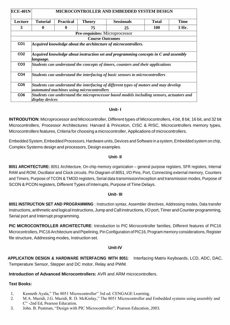
ECE-401N MICROCONTROLLER AND EMBEDDED SYSTEM DESIGN
Lecture Tutorial Practical Theory Sessionals Total Time
3 0 0 75 25 100 3 Hr.
Pre-requisites: Microprocessor Course Outcomes
CO1 Acquired knowledge about the architecture of microcontrollers.
CO2 Acquired knowledge about instruction set and programming concepts in C and assembly
language.
CO3 Students can understand the concepts of timers, counters and their applications
CO4 Students can understand the interfacing of basic sensors to microcontrollers
CO5 Students can understand the interfacing of different types of motors and may develop
automated machines using microcontrollers
CO6 Students can understand the microprocessor based models including sensors, actuators and display devices
Unit- I
INTRODUTION: Microprocessor and Microcontroller, Different types of Microcontrollers, 4 bit, 8 bit, 16 bit, and 32 bit
Microcontrollers, Processor Architectures: Harvard & Princeton, CISC & RISC, Microcontrollers memory types,
Microcontrollers features, Criteria for choosing a microcontroller, Applications of microcontrollers.
Embedded System, Embedded Processors, Hardware units, Devices and Software in a system, Embedded system on chip,
Complex Systems design and processors, Design examples.
Unit- II
8051 ARCHITECTURE: 8051 Architecture, On-chip memory organization – general purpose registers, SFR registers, Internal
RAM and ROM, Oscillator and Clock circuits. Pin Diagram of 8051, I/O Pins, Port, Connecting external memory, Counters
and Timers, Purpose of TCON & TMOD registers, Serial data transmission/reception and transmission modes, Purpose of
SCON & PCON registers, Different Types of Interrupts, Purpose of Time Delays.
Unit- III
8051 INSTRUCTION SET AND PROGRAMMING : Instruction syntax, Assembler directives, Addressing modes, Data transfer
instructions, arithmetic and logical instructions, Jump and Call instructions, I/O port, Timer and Counter programming,
Serial port and Interrupt programming.
PIC MICROCONTROLLER ARCHITECTURE: Introduction to PIC Microcontroller families, Different features of PIC16
Microcontrollers, PIC16 Architecture and Pipelining, Pin Configuration of PIC16, Program memory considerations, Register
file structure, Addressing modes, Instruction set.
Unit-IV
APPLICATION DESIGN & HARDWARE INTERFACING WITH 8051: Interfacing Matrix Keyboards, LCD, ADC, DAC,
Temperature Sensor, Stepper and DC motor, Relay and PWM.
Introduction of Advanced Microcontrollers: AVR and ARM microcontrollers.
Text Books:
1. Kenneth Ayala,” The 8051 Microcontroller” 3rd ed. CENGAGE Learning.
2. M.A. Mazidi, J.G. Mazidi, R. D. McKinlay,” The 8051 Microcontroller and Embedded systems using assembly and
C” -2nd Ed, Pearson Education. 3. John. B. Peatman, “Design with PIC Microcontroller”, Pearson Education, 2003.

References Books:
1. Myke Predko, “Programming and Customizing the 8051 Microcontroller”, TMH.
2. Manish K Patel,”Microcontroller based embedded system”, McGraw Hill Education.
3. Raj Kamal, “Embedded systems architecture, programming and design”-2nd nd. McGraw-Hill Companies.

4. Intel’s manual on “Embedded Microcontrollers”.
5. Myke Predko, “Programming and customizing PIC microcontroller” Mc- Graw Hill.
6. M.A. Mazidi, R. D. McKinlay,Causey,” The PIC microcontroller and Embedded Systems using assembly and C for
PIC18” -2nd Ed, Pearson.
7. M.A. Mazidi,Naimi” The AVR microcontroller and Embedded Systems using assembly and C” -2nd Ed, Pearson.
Lecture Plan
Lecture No. Topic
Unit- I: INTRODUCTION
L1 Introduction to Embedded Systems and difference between Microprocessor and Microcontroller
L2 Different types of Microcontrollers: 4 bit, 8 bit, 16 bit, and 32 bit Microcontrollers
L3 Processor Architectures: Harvard & Princeton, CISC & RISC, Microcontrollers memory types
L4 Microcontrollers features, Criteria for choosing a microcontroller, Applications of
microcontrollers.
L5 Embedded System, Embedded Processors, Hardware units
L6 Devices and Software in a system, Embedded system on chip
L7 Complex Systems design and processors, Design examples.
Unit- II: 8051 ARCHITECTURE
L8 8051 Architecture (Block Diagram) and Pin Diagram of 8051
L9 On-chip memory organization – general purpose registers, SFR registers
L10 Internal RAM and ROM, Oscillator and Clock circuits
L11 I/O Pins, Port
L12 Connecting external memory
L13 Counters and Timers Purpose of Time Delays.
L14 Purpose of TCON & TMOD registers
L15 Serial data transmission/reception and transmission modes
L16 Purpose of SCON & PCON registers, Different Types of Interrupts
Unit- III: 8051 INSTRUCTION SET AND PROGRAMMING
L17 Instruction syntax, Assembler directives and Addressing modes
L18 Data transfer instructions
L19 Arithmetic and logical instructions
L20 Jump and Call instructions
L21 I/O port
L22 Timer and Counter programming
L23 Serial port Programming
L24 Interrupt programming
PIC MICROCONTROLLER ARCHITECTURE:
L25 Introduction to PIC Microcontroller families, Different features of PIC16 Microcontrollers
L26 PIC16 Architecture and Pipelining, Pin Configuration of PIC16
L27 Program memory considerations, Register file structure
L28 Addressing modes, Instruction set
Unit-IV: APPLICATION DESIGN & HARDWARE INTERFACING WITH 8051:
L29 Interfacing Matrix Keyboards
L30 Interfacing LCD
L31 Interfacing ADC
L32 Interfacing DAC
L33 Interfacing Temperature Sensor
L34 Interfacing Stepper and DC motor
L35 Interfacing Relay and PWM

L36 AVR and ARM microcontrollers
Tutorial Sheet 1
1. Define an embedded system and describe its important features. List Few applications of embedded
systems.
2. What are different ways of classifying the microcontrollers? Explain the classification of microcontrollers
based on their data lines.
3. With the help of a diagram, explain why hardware architecture is preferred over prineton architecture.
4. Differentiate between following
i) Harvarol vs Princeton architecture
ii) CISC vs RISC
iii) Microprocessors Vs Microcontrollers
iv) OTP and Flash Memory
5. Compare and contrast 8051, 8031 and 8751 microcontrollers. Discuss the criteria for choosing these
microcontrollers for particular application.
6. Explain a design example of embedded system on chip.
Tutorial Sheet 2
1. Draw the block diagram of 8051 microcontroller and describe functions of DPTR and PC registers of 8051.
2. Find the THL needed to have the band rate of 2400 with the crystal frequency of 11.0592 MHz.
3. What is the difference between external and software generated interrupts? Discuss the applications of
interrupts.
4. Draw pin diagram of 8051 microcontrollers and explain function of each pin.Also discuss the difference
between Part 0, Part 1, Part 2 and Part 3 functions.
5. Describe all times modes of 8051 microcontroller.
Tutorial Sheet 3
1. Explain the addressing modes of 8051 microcontroller.
2. What are assembler directives. Give example of assembler directive used in 8051
microcontroller. 3. Explain the function of following instructions with the help of an example of each.
1) CJNE 2) MOVC 3)DJN
4. Write an assembly language program to find maximum number among array of N numbers.
5. Write an assembly language program to produce a software delay of 1 minute.
Tutorial Sheet 4
1. Explain the interface of a matrix keypad with 8051 microcontroller.
2. Draw interfacing diagram of DAC with 8051 microcontroller and write ALP to generate
saw tooth waveform at the output of DAC. 3. Discuss the interfacing of LCD display and write a program to display ‘CONTROLLER

8051’.
4. Write an assembly language program to measure width of pulse.
5. Explain speed control of DC motor using PWM.


ECE-
403N
DIGITAL IMAGE PROCESSING
Lecture Tutorial Practical Theory Sessionals Total Time
4 0 0 75 25 100 3 Hr.
Course Outcomes
CO1 Students will understand the need of Digital Image processing
CO2 Students will be able to explain the basics of Digital Image processing
CO3 Student will be able to explain sampling and quantization of digital image
CO4 Students will understand the concepts of color images
CO5 Student will be able to analyze the image enhancement operations on digital image
CO6 Students will be able to analyze the various image analysis and computer vision algorithm
Unit-I
Introduction: Processing and applications, Image representation and modeling, Image Enhancement, Restoration, analysis,
reconstruction from Projections, Image Data Compression. Image Perception: Light, Luminance, Brightness, Contrast, MFT
of visual System, Visibility Function, Image fidelity, Color representation, color matching and reproduction, color vision
Model
Unit-II
Image sampling and Quantization: Introduction, Two dimensional sampling theory, practical limitations in sampling and
reconstruction, Image quantization, Optimum mean square or Lloyd-Max quantizer.
Unit-III
Image Enhancement: Introduction, Point Operation, Histogram Modeling, Spatial Operations, Transform Operations,
Multispectral Image enhancement, Color Image enhancement.
Unit-IV
Image Analysis and Computer Vision: Introduction, Spatial Feature Extraction, Transform features, Edge Detection,
Boundary Extraction, Shape features, Image segmentation.
Text Books:
1. Digital Image Processing, third edition by Rafael C. Gonzalez and Richard E Woods. Publisher: Pearson Education.
2. Digital Image Processing by S. Sridhar , Publisher: Oxford
Reference Books:
1. Fundamentals of Digital Image Processing by Anil K Jain, Publisher: Prentice Hall

L-1: Introduction to images and processing.
L-2: Image Representation and modeling.
Digital Image Processing
Lecture Plan
L-3: Familiarization with image Enhancement, Restoration, Analysis.
L-4: Familiarization with image reconstruction from Projections, Compression.
L-5: Image Perception: Light, Luminance, Brightness and Contrast.
L-6: MFT of visual system, Visibility function.
L-7: Visibility function, Image fidelity.
L-8: Color Representation,
L-9: Color matching and Reproduction.
L-10: Color vision model.
L-11: Two-dimensional sampling theory.
L-12: Practical limitation in sampling and quantization.
L-13: Image quantization.
L-14: Optimum mean square quantizer.
L-15: Optimum mean square quantizer continues.
L-16: Introduction to image enhancement.
L-17: Point operations.
L-18: Histogram Modeling.
L-19: Spatial operations.
L-20: Transform operations.
L-21: Multi-spectral image enhancement.
L-22: Color image enhancement.
L-23: Color image enhancement continues.
L-24: Introduction to computer vision.
L-25: Spatial feature extraction.
L-26: Spatial feature extraction continues.
L-27: Transform features.
L-28: Transform features continue.
L-29: Edge detection.
L-30: Edge detection continues.
L-31: Boundary extraction.
L-32: Boundary extraction continues.

L-33: Shape features.
L-34: Shape features continue.
L-35: Image Segmentation.
L-36: Image Segmentation continues.
Tutorial Sheets
Tutorial No 1
Q1. Draw and explain image capturing mechanism.
Q2. Draw and explain MFT of a visual system.
Q3. Explain image fidelity.
Q4. Explain color vision model.
Q5. What is a difference between luminance, brightness and contrast.
Tutorial No 2
Q1. Explain two dimensional sampling with suitable example.
Q2. What is quantization and its impact on quality.
Q3. Explain Lloyd-Max quantizer.
Q4. Capture an image with different sampling rate and compare.
Tutorial No 3
Q1. What are various point operations?
Q2. What are various Transform operations?
Q3. What is Multi-spectral image enhancement?
Q4. What is color image enhancement?
Tutorial No 4
Q1. Explain different spatial feature extraction technique.
Q2. Explain edge detection with example.
Q3. What is boundary extraction?
Q4. What are various techniques of image segmentation?


ECE-405N POWER ELECTRONICS
Lecture Tutorial Practical Theory Sessionals Total Time
3 0 0 75 25 100 3 Hr.
Purpose To understand and acquire knowledge about various power semiconductor devices.
To prepare the students to analyze and design different power converter circuits.
Course Outcomes
CO1 Acquire knowledge about fundamental concepts and techniques used in power
electronics.
CO2 Ability to analyze various single phase and three phase power converter circuits and
understand their applications.
CO3 Foster ability to identify basic requirements for power electronics based design
application.
CO4 To develop skills to build, and troubleshoot power electronics circuits.
CO5 Identify the critical areas in application levels and derive typical alternative solutions,
select suitable power converters to control Electrical Motors and other industry grade
apparatus
CO6 Recognize the role power electronics play in the improvement of energy usage
efficiency and the applications of power electronics in emerging areas
Unit-1
Introduction: Concept of Power Electronics, Applications of power electronics, Advantages and disadvantages of power-
electronic converters, Power electronic systems, Power semiconductor devices, Types of power electronic converters. Power
semiconductors: The p-n junction, Basic structure of power diodes, Characteristics of power diodes, Power transistors,
Power MOSFETS, Insulated gate bipolar transistor, Static induction transistor.
Unit-II
Thyristors :Terminal characteristics of thyristors, thyristor turn on methods, Switching characteristics of thyristors,
Thyristor gate characteristics, Two-transistor model of a thyristor, Thyristor ratings, Thyristor protection, Improvement of
thyristor characteristics, Series and parallel operation of thyristors, Gate turn off thyristor, Firing circuits for thyristors.
Thyristor Commutation: Class A commutation: Load commutation, Class B commutation: Resonant commutation, Class
C commutation: Complementary commutation, Class D commutation: Impulse commutation, Class E&F commutation.
Unit–III
Phase Controlled Rectifiers: Principle of phase control, Full wave controlled converters, Single phase full wave
converters, Single phase symmetrical and asymmetrical semi converters, three phase rectifiers and thyristor converters,
Performance parameters of three phase full converters, Effect of source impedance on the performance of converters.
Principle of chopper operation, Control strategies, Step up choppers, Types of chopper circuits, Single phase voltage source
inverters: Operating principle, Force commutated thyristor inverters, Voltage control in single phase inverters.
Unit-IV
AC Voltage Controllers: Principle of phase control, Principle of integral cycle control, single phase ac voltage controller
with R load and RL load.
Cycloconverters: Principle of cycloconverter operation, step up and step down cycloconverters, Three phase half wave
converters, Output voltage equation for a cycloconverter, Load commutated cycloconverter.
Text Books
1. P S Bimbhra: Power Electronics, Khanna Publishers.

Reference Books
1. M. H. Rashid. : Power Electronics – circuits, devices & applications, Pearson Education

POWER ELECTRONICS
(ECE-405N)
LECTURE PLAN
LECTURES TOPICS
L1 Concept of Power Electronics, Applications of Power
Electronics
L2 Advantages & Disadvantages of Power electronic converters,
Power Electronic systems
L3 Power semiconductor devices, Types of power electronic
Converters
L4 Power semiconductors: The p-n junction, Basic structure of
power diodes
L5 Characteristics of power diodes
L6 Power transistors
L7 Power MOSFETS
L8 Insulated gate bipolar transistor & static gate induction
Transistor
L9 Terminal characteristics of thyristors, Thyristor turn on methods
L10 Switching characteristics of thyristors, Thyristor gate
Characteristics
L11 Two-transistor model of a thyristor, Thyristor ratings
L12 Thyristor protection, Improvement of thyristor characteristics
L13 Series & Parallel operation of thyristors, Gate turn off thyristor
L14 Firing circuits for thyristors
L15 Thyristor Commutation: Class A commutation: Load
commutation
L16 Class B commutation: Resonant commutation
L17 Class C commutation: Complementary commutation, Class D
Commutation: Impulse commutation
L18 Class E&F commutation
L19 Principle of phase control, Full wave controlled converters
L20 Single Phase full wave converters
L21 Single phase symmetrical & asymmetrical semi converters
L22 Three phase rectifiers & thyristor converters
L23 Performance parameters of three phase full converters
L24 Effect of source impedance on the performance of converters
L25 Principle of chopper operation, Control strategies
L26 Step up choppers
L27 Types of Chopper circuits
L28 Single phase voltage source inverters: Operating Principle
L29 Force commutated thyristor inverters
L30 Voltage control in single phase inverters
L31 AC Voltage Controllers: Principle of phase control
L32 Principle of integral cycle control
L33 Single phase ac voltage controller with R load & RL Load
L34 Principle of cycloconverter operation
L35 Step up & Step down cycloconverters
L36 Three phase half wave converters
L37 Output voltage equation for a cycloconverter
L38 Load commutated cycloconverter
TUTORIAL SHEET-1
1. Explain the concept of Power Electronics

2. What are the advantages & disadvantages of Power Electronic converters.
3. Explain different types of Power Electronic converters.
4. Describe the basic structure of power diodes.
5. Explain the concept of Power transistors.
TUTORIAL SHEET-2
1. Explain terminal characteristics of thyristors.
2. Explain thyristor gate characteristics.
3. Explain the Two-transistor model of a thyristor.
4. Explain the Series & Parallel operation of thyristors.
5. Explain the concept of Thyristor Commutation.
TUTORIAL SHEET-3
1. Explain the working of full wave controlled converters.
2. Explain three phase rectifiers & thyristor converters.
3. Explain the effect of source impedance on performance of converters.
4. Explain principle of chopper operation.
5. Explain the operating principle of single phase voltage source inverters.
TUTORIAL SHEET-4
1. Explain the principle of phase control for AC Voltage Controllers.
2. Explain the principle of integral cycle control.
3. Describe single phase ac voltage controller with R load & RL load.
4. Explain thr principle of operation of cycloconverters.
5. Explain the working of step up & step down cycloconverters.
TUTORIAL SHEET-5
1. Explain the working of Power MOSFETS.
2. Explain firing circuits for thyristors.
3. Explain various performance parameters of three phase full converters.
4. Explain different types of chopper circuits.
5. Explain Class A, Class B & Class C thyristor commutation.


ECE -
419N
OPTICAL COMMUNICATION
Lecture Tutorial Practical Theory Sessionals Total Time
3 0 0 75 25 100 3 Hr.
Purpose To familiarize the students with the concepts of Optical communication covering the contents of
optical fibers, losses in fibers, optical sources, detectors etc.
Course Outcomes
CO1 Students will be able to understand the structure of fiber and the mechanism of light travelling in the fiber.
CO2 Students will be able to understand different types of fibers & power launching-coupling methods
CO3 Students will be able to analyze various losses associated with fibers.
CO4 Students will learn about the optical sources and optical detecters.
CO5 Students will become familiar with design considerations of fiber optic systems
CO6 Students will be able to understand the various components needed in optical networks
Unit – I
INTRODUCTION : Optical Fibers: Structure, Propagation within the fiber, Numerical aperture of fiber, step index and
graded index fiber, Modes of propagation in the fiber, Single mode and multi mode fibers. Splices and connectors. Optical
Power Launching and Coupling. Fiber-to-fiber joints.
Unit–II
LOSSES IN OPTICAL FIBER : Rayleigh Scattering Losses, Absorption Losses, Leaky modes, Mode coupling losses,
Bending Losses, Combined Losses in the fiber.
DISPERSION EFFECT: Effect of dispersion on the pulse transmission Intermodal dispersion, Material dispersion, Wave
guide dispersion, Polarization Mode Dispersion Total dispersion, Transmission rate. Dispersion Shifted Fibers, Dispersion
Compensating Fibers.
Unit – III
LIGHT SOURCES : LEDS, Laser Action in semiconductor Lasers, Semiconductor Lasers for optical communication –
Laser modes, Spectral Characteristics, Power Voltage Characteristics, Frequency response.
DETECTORS : P-I-N Photodiode, APD, Noise Analysis in detectors, Coherent and non-coherent detection, Infrared
sensors. Bit error rate.
Unit– IV
THE FIBER-OPTIC COMMUNICATION SYSTEM: Design considerations of fiber optic systems: Analog and digital
modulation. Optical Devices: Optical coupler, space switches, linear divider-combiners, wavelength division multiplexer
and demultiplexer, optical amplifier
OPTICAL NETWORKS: Elements and Architecture of Fiber-Optic Network, Optical link network-single hop , multihop,
hybrid and photonic networks.
Suggested Books:
1. John Power, An Introduction to Fiber optic systems, McGraw Hill International.

2. John Gowar , Optical communication Systems.
3. R. Ramaswamy, Optical Networks, Narosa Publication
4. John M. Senior,Optical Fiber Communication
5. Gerd Keiser, Optical Fiber Communication
OPTICAL COMMUNICATION
(ECE-419N)
LECTURE PLAN
LECTURES TOPICS
L1 Optical Fibers: Structure, Propagation within the fiber
L2 Numerical aperture of fiber
L3 step index and graded index fiber
L4 Modes of propagation in the fiber
L5 Single mode and multi mode fibers
L6 Splices and connectors
L7 Optical Power Launching and Coupling
L8 Fiber-to-fiber joints
L9 Rayleigh Scattering Losses
L10 Absorption Losses, Leaky modes
L11 Mode coupling losses, Bending Losses
L12 Combined Losses in the fiber
L13 Effect of dispersion on the pulse transmission
L14 Intermodal dispersion, Material dispersion
L15 Wave guide dispersion, Polarization Mode Dispersion
L16 Total dispersion
L17 Transmission rate
L18 Dispersion Shifted Fibers
L19 Dispersion Compensating Fibers
L20 LEDS, Laser Action in semiconductor Lasers
L21 Semiconductor Lasers for optical communication
L22 Laser modes, Spectral Characteristics
L23 Power Voltage Characteristics
L24 Frequency Response
L25 P-I-N Photodiode
L26 APD, Noise Analysis in detectors
L27 Coherent and non-coherent detection
L28 Infrared Sensors, Bit error rate
L29 Design considerations of fiber optic systems: Analog and digital
modulation
L30 Optical Devices: Optical coupler
L31 Space switches, linear divider-combiners
L32 Wavelenth Divison Multiplexer & Demultiplexer
L33 Optical Amplifier
L34 Elements and Architecture of Fiber-Optic Network
L35 Optical link network-single hop , multihop
L36 Hybrid and photonic networks

TUTORIAL SHEET -1
1. What are the advantages of Optical Fiber Communication?
2. Explain different modes of propagation in optical fiber.
3. State differences between step index & graded index fiber.
4. Explain splices & connectors used in optical fiber communication..
5. Explain the concept of Optical Power Launching & Coupling.
TUTORIAL SHEET -2
1. What are different losses in a fiber.
2. Explain difference between single mode & multi mode fiber.
3. An optical signal has lost 55 percent of its power after traversing 3.5 km of fiber. What is the loss in db/Km in
this fiber.
4. Explain Polarization mode dispersion.
5. Explain dispersion shifted & dispersion compensating fibers.
TUTORIAL SHEET -3
1. Explain the effect of dispersion on pulse transmission.
2. Explain pulse broadening in graded index fiber.
3. Explain inter model & intra model dispersion.
4. What is the difference between material dispersion & waveguide dispersion?
5. Write short note on APD noise.
TUTORIAL SHEET -4
1. Explain different types of LEDs.
2. Plot spectral characteristics & power voltage characteristics of semiconductor laser.
3. Explain the operation of p-i-n photodiode.
4. Explain fiber optic communication system.
5. Explain power characteristics of laser.
TUTORIAL SHEET -5
1. Explain Optical couplers & space switches.
2. Explain wavelength division multiplexer & de-multiplexer.
3. Explain optical amplifier.
4. Explain single hop & multi hop network.
5. Explain hybrid & photonic networks.


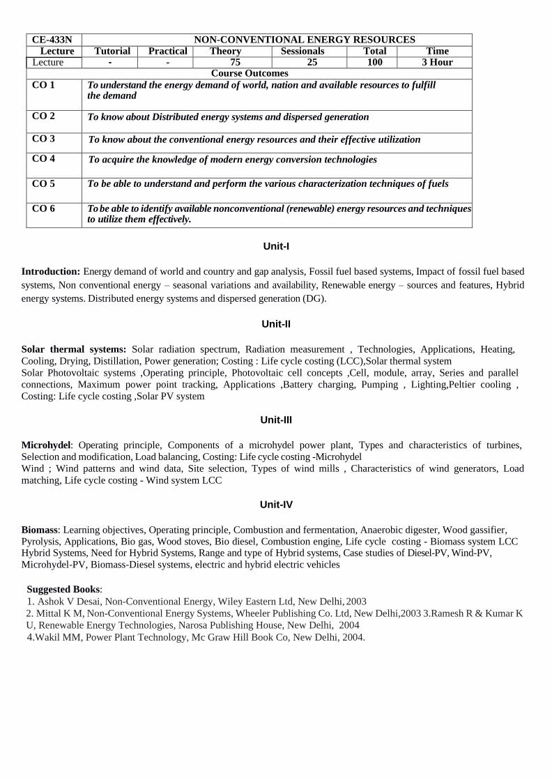
CE-433N NON-CONVENTIONAL ENERGY RESOURCES Lecture Tutorial Practical Theory Sessionals Total Time
Lecture - - 75 25 100 3 Hour Course Outcomes
CO 1 To understand the energy demand of world, nation and available resources to fulfill the demand
CO 2 To know about Distributed energy systems and dispersed generation
CO 3 To know about the conventional energy resources and their effective utilization
CO 4 To acquire the knowledge of modern energy conversion technologies
CO 5 To be able to understand and perform the various characterization techniques of fuels
CO 6 To be able to identify available nonconventional (renewable) energy resources and techniques to utilize them effectively.
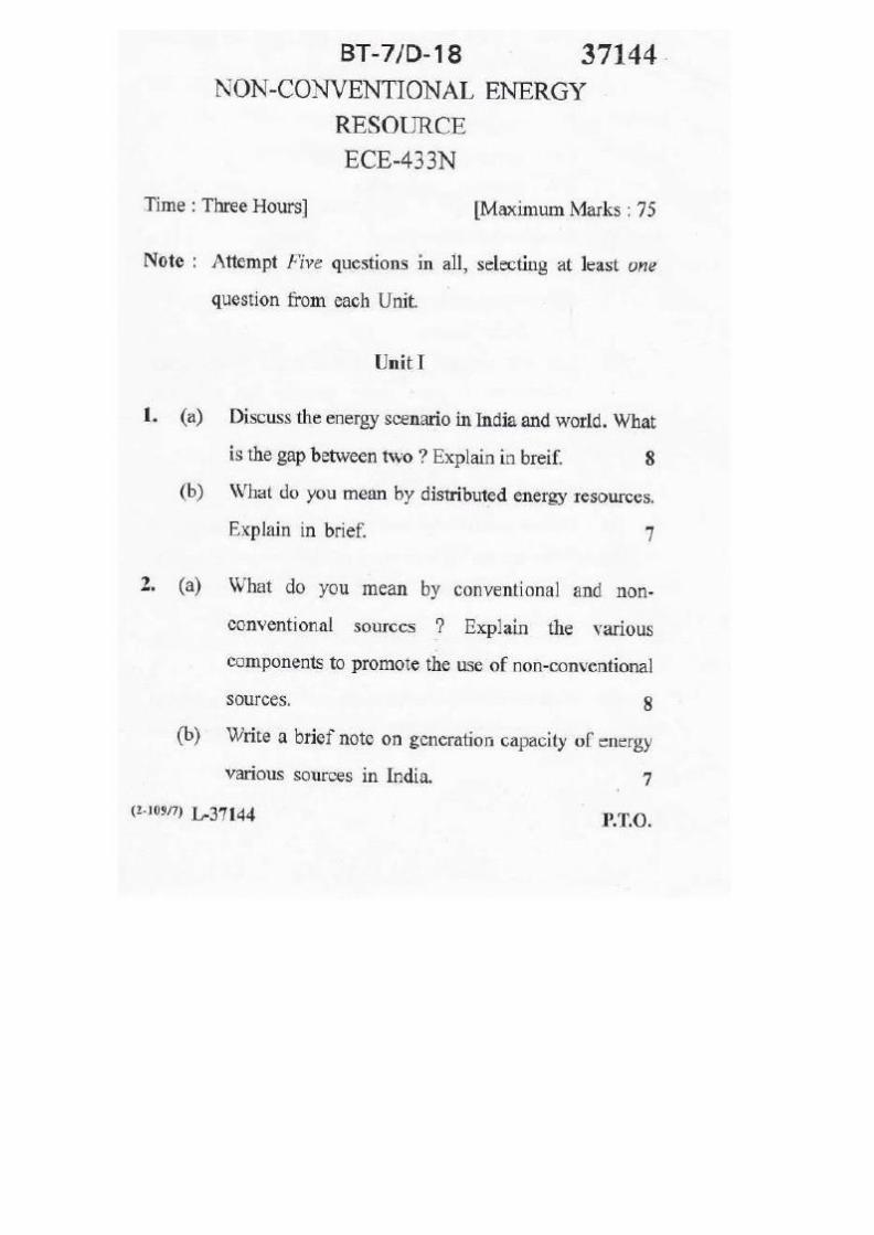
Unit-I
Introduction: Energy demand of world and country and gap analysis, Fossil fuel based systems, Impact of fossil fuel based
systems, Non conventional energy – seasonal variations and availability, Renewable energy – sources and features, Hybrid
energy systems. Distributed energy systems and dispersed generation (DG).
Unit-II
Solar thermal systems: Solar radiation spectrum, Radiation measurement , Technologies, Applications, Heating,
Cooling, Drying, Distillation, Power generation; Costing : Life cycle costing (LCC),Solar thermal system
Solar Photovoltaic systems ,Operating principle, Photovoltaic cell concepts ,Cell, module, array, Series and parallel
connections, Maximum power point tracking, Applications ,Battery charging, Pumping , Lighting,Peltier cooling ,
Costing: Life cycle costing ,Solar PV system
Unit-III
Microhydel: Operating principle, Components of a microhydel power plant, Types and characteristics of turbines,
Selection and modification, Load balancing, Costing: Life cycle costing -Microhydel
Wind ; Wind patterns and wind data, Site selection, Types of wind mills , Characteristics of wind generators, Load
matching, Life cycle costing - Wind system LCC
Unit-IV
Biomass: Learning objectives, Operating principle, Combustion and fermentation, Anaerobic digester, Wood gassifier, Pyrolysis, Applications, Bio gas, Wood stoves, Bio diesel, Combustion engin–e, Life cycle costing - Biomass system LCC Hybrid Systems, Need for Hybrid Systems, Range and type of Hybrid systems, Case studies of Diesel-PV, Wind-PV,
Microhydel-PV, Biomass-Diesel systems, electric and hybrid electric vehicles
Suggested Books:
1. Ashok V Desai, Non-Conventional Energy, Wiley Eastern Ltd, New Delhi, 2003 2. Mittal K M, Non-Conventional Energy Systems, Wheeler Publishing Co. Ltd, New Delhi,2003 3.Ramesh R & Kumar K
U, Renewable Energy Technologies, Narosa Publishing House, New Delhi, 2004
4.Wakil MM, Power Plant Technology, Mc Graw Hill Book Co, New Delhi, 2004.
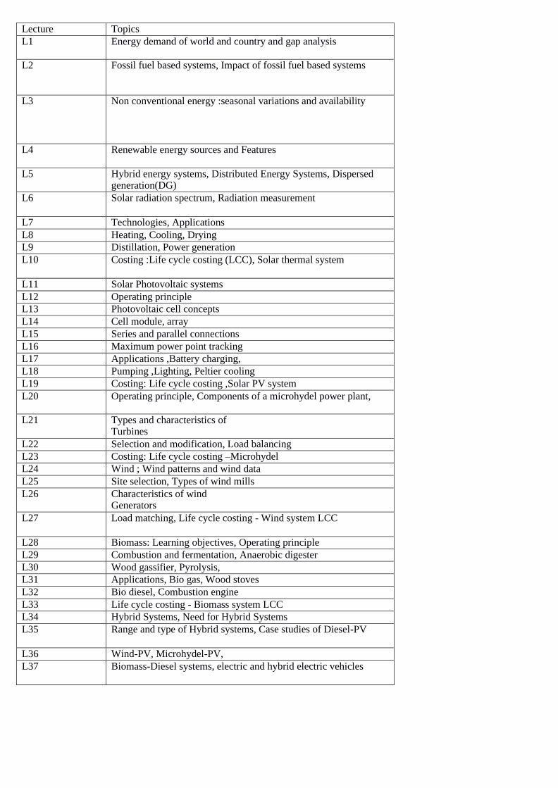
Lecture Topics
L1 Energy demand of world and country and gap analysis
L2 Fossil fuel based systems, Impact of fossil fuel based systems
L3 Non conventional energy :seasonal variations and availability
L4 Renewable energy sources and Features
L5 Hybrid energy systems, Distributed Energy Systems, Dispersed generation(DG)
L6 Solar radiation spectrum, Radiation measurement
L7 Technologies, Applications
L8 Heating, Cooling, Drying
L9 Distillation, Power generation
L10 Costing :Life cycle costing (LCC), Solar thermal system
L11 Solar Photovoltaic systems
L12 Operating principle
L13 Photovoltaic cell concepts
L14 Cell module, array
L15 Series and parallel connections
L16 Maximum power point tracking
L17 Applications ,Battery charging,
L18 Pumping ,Lighting, Peltier cooling
L19 Costing: Life cycle costing ,Solar PV system
L20 Operating principle, Components of a microhydel power plant,
L21 Types and characteristics of Turbines
L22 Selection and modification, Load balancing
L23 Costing: Life cycle costing –Microhydel
L24 Wind ; Wind patterns and wind data
L25 Site selection, Types of wind mills
L26 Characteristics of wind Generators
L27 Load matching, Life cycle costing - Wind system LCC
L28 Biomass: Learning objectives, Operating principle
L29 Combustion and fermentation, Anaerobic digester
L30 Wood gassifier, Pyrolysis,
L31 Applications, Bio gas, Wood stoves
L32 Bio diesel, Combustion engine
L33 Life cycle costing - Biomass system LCC
L34 Hybrid Systems, Need for Hybrid Systems
L35 Range and type of Hybrid systems, Case studies of Diesel-PV
L36 Wind-PV, Microhydel-PV,
L37 Biomass-Diesel systems, electric and hybrid electric vehicles

TUTORIAL SHEET-I
1. Explain Energy demand of world and country and gap analysis.
2. Explain different Fossil fuel based systems and its Impact.
3. Explain Renewable energy – sources and features.
4. Explain Distributed energy systems and dispersed generation (DG).
TUTORIAL SHEET-II
1. Explain solar radiation spectrum and radiation measurement.
2. Discuss solar thermal systems and its applications.
3. Explain Operating principle of Solar Photovoltaic systems.
4. Explain in brief Solar PV system.
TUTORIAL SHEET-III
1. Discuss different components of a microhydel power plant.
2. Explain Types and characteristics of turbines.
3. What are various parameters for site selection?
4. Explain types of wind mills in detail.
TUTORIAL SHEET-IV
1. Explain Operating principle and objectives of biomass.
2. Discuss the concept of Combustion and fermentation.
3. Explain need for Hybrid Systems and its types.
4. Explain electric and hybrid electric vehicles in detail.
3

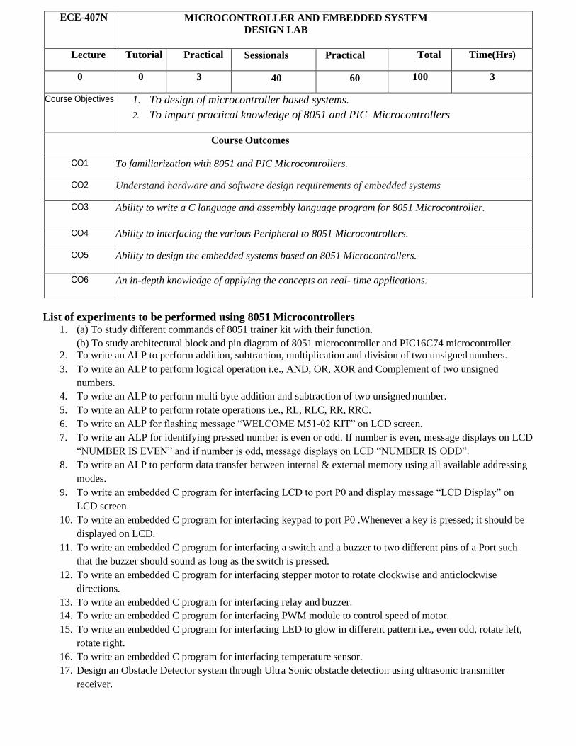
ECE-407N MICROCONTROLLER AND EMBEDDED SYSTEM
DESIGN LAB
Lecture Tutorial Practical Sessionals Practical Total Time(Hrs)
0 0 3 40 60 100 3
Course Objectives 1. To design of microcontroller based systems.
2. To impart practical knowledge of 8051 and PIC Microcontrollers
Course Outcomes
CO1 To familiarization with 8051 and PIC Microcontrollers.
CO2 Understand hardware and software design requirements of embedded systems
CO3 Ability to write a C language and assembly language program for 8051 Microcontroller.
CO4 Ability to interfacing the various Peripheral to 8051 Microcontrollers.
CO5 Ability to design the embedded systems based on 8051 Microcontrollers.
CO6 An in-depth knowledge of applying the concepts on real- time applications.
List of experiments to be performed using 8051 Microcontrollers 1. (a) To study different commands of 8051 trainer kit with their function.
(b) To study architectural block and pin diagram of 8051 microcontroller and PIC16C74 microcontroller.
2. To write an ALP to perform addition, subtraction, multiplication and division of two unsigned numbers.
3. To write an ALP to perform logical operation i.e., AND, OR, XOR and Complement of two unsigned
numbers.
4. To write an ALP to perform multi byte addition and subtraction of two unsigned number.
5. To write an ALP to perform rotate operations i.e., RL, RLC, RR, RRC.
6. To write an ALP for flashing message “WELCOME M51-02 KIT” on LCD screen.
7. To write an ALP for identifying pressed number is even or odd. If number is even, message displays on LCD
“NUMBER IS EVEN” and if number is odd, message displays on LCD “NUMBER IS ODD”.
8. To write an ALP to perform data transfer between internal & external memory using all available addressing
modes.
9. To write an embedded C program for interfacing LCD to port P0 and display message “LCD Display” on
LCD screen.
10. To write an embedded C program for interfacing keypad to port P0 .Whenever a key is pressed; it should be
displayed on LCD.
11. To write an embedded C program for interfacing a switch and a buzzer to two different pins of a Port such
that the buzzer should sound as long as the switch is pressed.
12. To write an embedded C program for interfacing stepper motor to rotate clockwise and anticlockwise
directions.
13. To write an embedded C program for interfacing relay and buzzer.
14. To write an embedded C program for interfacing PWM module to control speed of motor.
15. To write an embedded C program for interfacing LED to glow in different pattern i.e., even odd, rotate left,
rotate right.
16. To write an embedded C program for interfacing temperature sensor.
17. Design an Obstacle Detector system through Ultra Sonic obstacle detection using ultrasonic transmitter
receiver.
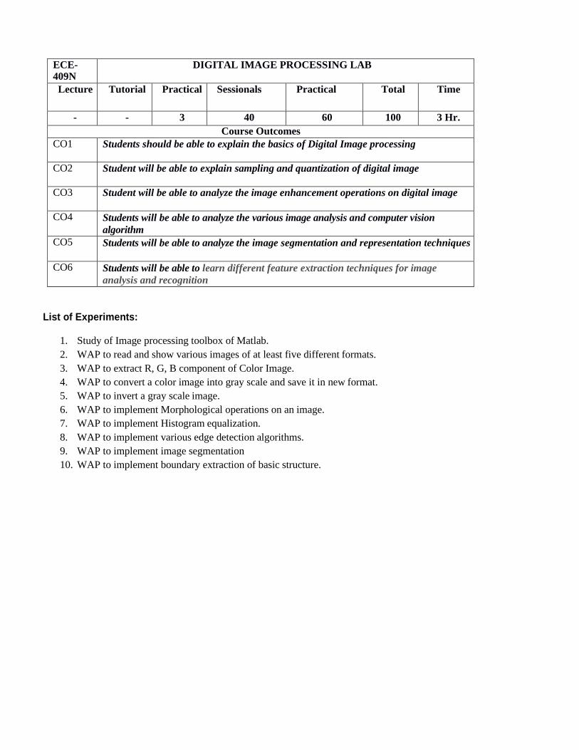
ECE- 409N
DIGITAL IMAGE PROCESSING LAB
Lecture Tutorial Practical Sessionals Practical Total Time
- - 3 40 60 100 3 Hr.
Course Outcomes
CO1 Students should be able to explain the basics of Digital Image processing
CO2 Student will be able to explain sampling and quantization of digital image
CO3 Student will be able to analyze the image enhancement operations on digital image
CO4 Students will be able to analyze the various image analysis and computer vision
algorithm
CO5 Students will be able to analyze the image segmentation and representation techniques
CO6 Students will be able to learn different feature extraction techniques for image
analysis and recognition
List of Experiments:
1. Study of Image processing toolbox of Matlab.
2. WAP to read and show various images of at least five different formats.
3. WAP to extract R, G, B component of Color Image.
4. WAP to convert a color image into gray scale and save it in new format.
5. WAP to invert a gray scale image.
6. WAP to implement Morphological operations on an image.
7. WAP to implement Histogram equalization.
8. WAP to implement various edge detection algorithms.
9. WAP to implement image segmentation
10. WAP to implement boundary extraction of basic structure.