s-ka s-kak s-kah a4 s-kah hcr s-kar a2 hha a2 … · hot dip galvanized acc. en iso 10684, t ≥ 40...
TRANSCRIPT

SORMAT SORMAT PDS-S-KA-EN-2018-05-03
S-K
A, S
-KA
K, S
-KA
H, S
-KA
H H
CR
TH
RO
UG
H B
OLT
1
PRODUCT DATA SHEET
www.sormat.com
facebook.com/sormat
youtube.com/sormatfixing
S-KA S-KAK S-KAH A4 S-KAH HCR S-KAR A2 HHA A2
THROUGH BOLTS

Premium-quality through bolts for fixing in cracked and non-cracked concrete
SORMAT PDS-S-KA-EN-2018-05-03
S-K
A, S
-KA
K, S
-KA
H, S
-KA
H H
CR
TH
RO
UG
H B
OLT
2
THROUGH BOLT
The through bolt is a torque-controlled expansion anchor for use in cracked and non-cracked concrete. It is also suitable for installation in hard base materials such as solid brick (max. M8) or natural stone. The anchor is preassembled and can be installed directly through the fixture.
It is available• in zinc electroplated steel for indoor and dry applications.• in hot dip galvanized steel for damp interiors with occasional exposure to condensation and slightly cor-
rosive outside environments.• in stainless steel for outdoor applications subject to humidity, as well as installation in industrial and mari-
time environments.• in HCR stainless steel for aggressive conditions, chloride atmosphere and atmosphere with chemical pollution
such as tunnels, swimming pools etc.
Benefits• Fixing in cracked and non-cracked concrete, also suitable for hard materials such a natural stone, solid
clay brick • Torque-controlled expansion anchors for pre-, push-through and distance installations• When torque is applied the expansion clip expands developing frictional grip into the hole.• Anchor diameter and max. fixture thickness marked on the body.• Variable range of coatings and materials such a ZP, HDG, stainless steel A2, A4 and HCR 1.4529/1.4565
which supports for anchor selecting in different applications • Sormat Through bolts are manufactured reliably in Finland since 1970s
The threaded body is madeby cold forging giving the final
product high precision andmaking it very strong and hard.
Active knurlsensure a good grip
and quick tighteningof the anchor.
Due to the cold forging,the surface of the cone is very
hard and even.This ensures veryconsistent pull-out results.
A rounding eases theanchor’s insertion into
the hole especially wheninstalled through wood.
Nut and washer arepre assembled for an easy and quick installation.
The cylindrical shapeof the cone at the lower
end allows controlledre-expansion.
A chamfered lower end of the sleeve preventsjamming between the cone and the sleeve.
The thick expansion sleeveprovides good expansion reserves
Marking indicatesthe size of the anchor
and the maximumfixture thickness.
Punched bolt headprevents threaddestruction whilehammering.

S-KA carbon steelZinc electroplated acc. EN ISO 4042, t ≥ 5 µm
Dry indoor conditions, indoor with temporary
condensation
S-KAH A4 stainless steelA4 for indoor, outdoor, industrial use
and maritime climate
S-KAH A4 recommended when fire or corrosion
resistance is required.
S-KAR A2 stainless steelA2 for dry and humid indoor use, outdoor in rural
areas only
Suitable for minings and for fixing very thick
fixtures, such a thermal insulation and wood
structures to concrete
HHA A2 stainless steelA2 for dry and humid indoor use, outdoor in rural
areas only
Hammer hook anchor for suspension in tunnels
and mines
S-KAH HCR stainless steelHCR for extremely corrosive conditions,
such as high chlorine concentrations (swimming
halls) road tunnels and desulphurization plants.
S-KAK carbon steelHot dip galvanized acc. EN ISO 10684, t ≥ 40 µm
Humid indoor use, outdoor inland rural areas only
SORMAT SORMAT PDS-S-KA-EN-2018-05-03
S-K
A, S
-KA
K, S
-KA
H, S
-KA
H H
CR
TH
RO
UG
H B
OLT
3
Approved for Also suitable for
Cracked concrete
Solid clay brick(M8 max)
Non-cracked concrete
Natural stone
Base materials

APPROVALS / CERFICATIONS / APPLICATIONS
Description of document Authority/ Laboratory ID Additional info
European Technical Assessment
VTT EXPERT SERVICES LTD, Espoo
ETA-08/0173ETAG 001, Annex C /
CEN/TS 1992-4
Fire resistanceVTT EXPERT SERVICES
LTD, Espoo ETA-08/0173
EOTA TR 020 / ETAG 001, Annex C / CEN/TS
1992-4
Seismic resistanceVTT EXPERT SERVICES
LTD, EspooETA-08/0173 EOTA TR 045:C1
Russian Technical Approval
FAU FCS TC 4635-15Technical approval FAU FCS 31.07.2015
Sormat Trustfix anchor calculation software
Sormat Oy / S&P Software Consulting
TrustFIX anchor calculation
Through bolts CAD-blocks for AutoCAD
Sormat Oy file format: .dwg Blocks installation
instructions for AutoCAD
Through bolts components for TEKLA Structures
Sormat Oy
Tekla structures components instructions +
instructions video
YouTube installation videos
Sormat OyV5-Z_NbntmQ rf37gw9T98k
Sormat S-KA through bolt installation video
SORMAT PDS-S-KA-EN-2018-05-03
S-K
A, S
-KA
K, S
-KA
H, S
-KA
H H
CR
TH
RO
UG
H B
OLT
4
Additional information concerning all given data in the product data sheet
1. Sizes M8, M10, M12 and M16 with standard anchorage depth are included in ETA-approval, see ETA-08/0173. Sizes M6, M20 and all values with reduced effective anchorage depth (h
hef) are manufacturer’s recommendations.
2. Load figures include the partial safety factors as per approvals and a partial safety factor on the action of γF= 1.4.
Load figures apply for a rebar spacing s ≥ 15 cm or alternatively for a rebar spacing s ≥ 10 cm in combination with a rebar diameter of d
s ≤ 10 mm.
3. If spacings or edge distances become smaller than the characteristic figures (Scr,N
/ Ccr,N
) a calculation as per ETAG, Annex C, design method A needs to be carried out. For more details, see ETA-approval ETA-08/0173.
4. Concrete is considered non-cracked when the value of tension within the concrete is σL + σ
R ≤ 0. In the absence
of detailed verification σR = 3 N/mm² can be assumed (σ
L equals the tension within the concrete as a result
of external loads, forces on anchor included; σR equals the tension coming from shrinkage or creep of the
concrete, as well as displacements of supports or temperature variations).
5. Shear load figures apply for an anchor without influence of a concrete edge. For shear loads close to an edge (c ≤ 10 x h
ef), concrete edge failure has to be checked as per ETAG, Annex C, Design Method A.

Characteristic resistancesAnchor size M6 M8 M10 M12 M16 M20
Effective anchorage depth hef [mm] 25 35 30 45 30 60 55 70 60 85 110
Non-cracked concrete
Tensile NRk
S-KA/S-KAK [kN] 4,0 4,5 6,5 9,0 8,8 16,0 16,4 20,0 24,9 35,0 49,9
S-KAH/S-KAH HCR [kN] 4,0 4,5 6,5 9,0 8,8 16,0 16,4 20,0 24,9 35,0 49,9
Shear VRk
S-KA/S-KAK [kN] 3,1 4,8 10,1 10,1 10,1 18,0 17,2 23,0 23,5 44,0 58,2
S-KAH/S-KAH HCR [kN] 3,1 4,8 10,7 10,7 10,1 17,0 - 25,0 - 47,0 58,2
Cracked concrete
Tensile NRk
S-KA/S-KAK [kN] - - - 5,0 - 9,0 - 12,0 - 20,0 -
S-KAH/S-KAH HCR [kN] - - - 5,0 - 9,0 - 12,0 - 20,0 -
Shear VRk
S-KA/S-KAK [kN] - - - 10,0 - 18,0 - 23,0 - 44,0 -
S-KAH/S-KAH HCR [kN] - - - 11,0 - 17,0 - 25,0 - 47,0 -
Design resistancesAnchor size M6 M8 M10 M12 M16 M20
Effective anchorage depth hef
[mm] 25 35 30 45 30 60 55 70 60 85 110
Non-cracked concrete
Tensile NRd
S-KA/S-KAK [kN] 2,2 2,5 3,6 5,0 4,9 8,9 9,1 11,1 13,8 23,3 27,7
S-KAH/S-KAH HCR [kN] 2,2 2,5 3,6 5,0 4,9 8,9 9,1 11,1 13,8 23,3 27,7
Shear VRd
S-KA/S-KAK [kN] 2,1 2,5 6,7 8,0 8,3 14,4 11,5 18,4 15,7 35,2 36,4
S-KAH/S-KAH HCR [kN] 2,1 2,5 7,1 8,8 8,3 13,6 - 20,0 - 37,6 36,4
Cracked concrete
Tensile NRd
S-KA/S-KAK [kN] - - - 2,8 - 5,0 - 6,7 - 13,3 -
S-KAH/S-KAH HCR [kN] - - - 2,8 - 5,0 - 6,7 - 13,3 -
Shear VRd
S-KA/S-KAK [kN] - - - 7,3 - 14,4 - 18,4 - 35,2 -
S-KAH/S-KAH HCR [kN] - - - 7,3 - 13,6 - 20,0 - 37,6 -
SORMAT SORMAT PDS-S-KA-EN-2018-05-03
S-K
A, S
-KA
K, S
-KA
H, S
-KA
H H
CR
TH
RO
UG
H B
OLT
5
STATIC AND QUASI-STATIC LOADS
The data of these tables is based on: • Concrete C20/25, f
ck,cube = 25 N/mm².
• Installation has been done correctly (see page 10).• No influence of edge distances and spacings.• Respect of minimum base material thickness (see page 11).

Recommended loadsAnchor size M6 M8 M10 M12 M16 M20
Effective anchorage depth hef
[mm] 25 35 30 45 30 60 55 70 60 85 110
Non-cracked concrete
Tensile NRec
S-KA/S-KAK [kN] 1,6 1,8 2,6 3,6 3,5 6,3 6,5 7,9 9,9 16,7 19,8
S-KAH/S-KAH HCR [kN] 1,6 1,8 2,6 3,6 3,5 6,3 6,5 7,9 9,9 16,7 19,8
Shear VRec
S-KA/S-KAK [kN] 1,5 1,8 4,8 5,7 5,9 10,3 8,2 13,1 11,2 25,1 26,0
S-KAH/S-KAH HCR [kN] 1,5 1,8 5,1 6,3 5,9 9,7 - 14,3 - 26,9 26,0
Cracked concrete
Tensile NRec
S-KA/S-KAK [kN] - - - 2,0 - 3,6 - 4,8 - 9,5 -
S-KAH/S-KAH HCR [kN] - - - 2,0 - 3,6 - 4,8 - 9,5 -
Shear VRec
S-KA/S-KAK [kN] - - - 5,2 - 10,3 - 13,1 - 25,1 -
S-KAH/S-KAH HCR [kN] - - - 5,2 - 9,7 - 14,3 - 26,9 -
SORMAT PDS-S-KA-EN-2018-05-03
S-K
A, S
-KA
K, S
-KA
H, S
-KA
H H
CR
TH
RO
UG
H B
OLT
6
STATIC AND QUASI-STATIC LOADS
The data of these tables is based on: • Concrete C20/25, f
ck,cube = 25 N/mm².
• Installation has been done correctly (see page 10).• No influence of edge distances and spacings.• Respect of minimum base material thickness (see page 11).

Characteristic resistancesAnchor size M8 M10 M12 M16
Effective anchorage depth hef
[mm] 45 60 70 85
Cracked concrete
Tensile NRk
S-KA/S-KAK [kN] 5,0 9,0 12,0 20,0
S-KAH/S-KAH HCR [kN] 5,0 9,0 12,0 20,0
Shear VRk
S-KA/S-KAK [kN] 5,6 11,9 15,4 31,2
S-KAH/S-KAH HCR [kN] 8,7 11,2 18,3 31,5
Design resistancesAnchor size M8 M10 M12 M16
Effective anchorage depth hef
[mm] 45 60 70 85
Cracked concrete
Tensile NRd
S-KA/S-KAK [kN] 2,8 5,0 6,7 13,3
S-KAH/S-KAH HCR [kN] 2,8 5,0 6,7 13,3
Shear VRd
S-KA/S-KAK [kN] 4,5 9,5 12,3 25,0
S-KAH/S-KAH HCR [kN] 7,0 9,0 14,6 25,2
SORMAT SORMAT PDS-S-KA-EN-2018-05-03
S-K
A, S
-KA
K, S
-KA
H, S
-KA
H H
CR
TH
RO
UG
H B
OLT
7
SEISMIC RESISTANCEDesign acc. EOTA TR 045: Performance category C1
The data of these tables is based on: • Concrete C20/25, f
ck,cube = 25 N/mm².
• Installation has been done correctly (see page 10).• No influence of edge distances and spacings.• Respect of minimum base material thickness (see page 11).

Characteristic resistancesAnchor size M8 M10 M12 M16
Effective anchorage depth hef
[mm] 45 60 70 85
Fire Exposure R30
Tensile NRk
S-KA/S-KAK [kN] 1,3 2,3 3,0 5,0
S-KAH/S-KAH HCR [kN] 1,3 2,3 3,0 5,0
Shear VRk
S-KA/S-KAK [kN] 1,3 2,3 3,6 5,3
S-KAH/S-KAH HCR [kN] 2,4 9,1 13,2 24,0
Fire Exposure R120
Tensile NRk
S-KA/S-KAK [kN] 0,3 0,5 0,9 1,3
S-KAH/S-KAH HCR [kN] 1,0 1,8 2,6 4,8
Shear VRk
S-KA/S-KAK [kN] 0,3 0,5 0,9 1,3
S-KAH/S-KAH HCR [kN] 1,1 1,8 2,6 4,8
Recommended loadsAnchor size M8 M10 M12 M16
Effective anchorage depth hef
[mm] 45 60 70 85
Fire Exposure R30
Tensile NRec
S-KA/S-KAK [kN] 1,3 2,3 3,0 5,0
S-KAH/S-KAH HCR [kN] 1,3 2,3 3,0 5,0
Shear VRec
S-KA/S-KAK [kN] 1,3 2,3 3,6 5,3
S-KAH/S-KAH HCR [kN] 2,4 9,1 13,2 24,0
Fire Exposure R120
Tensile NRec
S-KA/S-KAK [kN] 0,3 0,5 0,9 1,3
S-KAH/S-KAH HCR [kN] 1,0 1,8 2,6 4,8
Shear VRec
S-KA/S-KAK [kN] 0,3 0,5 0,9 1,3
S-KAH/S-KAH HCR [kN] 1,1 1,8 2,6 4,8
SORMAT PDS-S-KA-EN-2018-05-03
S-K
A, S
-KA
K, S
-KA
H, S
-KA
H H
CR
TH
RO
UG
H B
OLT
8
FIRE RESISTANCE
The data of these tables is based on: • In the absence of other national regulations the partial safety factor for
resistance under fire exposure γM,fi = 1,0 is recommended
• Concrete C20/25, fck,cube
= 25 N/mm² • Installation has been done correctly (see page 10).• No influence of edge distances and spacings.• Respect of minimum base material thickness (see page 11).

Anchor dimensions Anchor size M6 M8 M10 M12 M16 M20
Length L1 [mm] 40…100 50…147 60…162 85…253 90…213 170…280
Sleeve length L2 [mm] 14,3 15,9 17,9 19,1 26,3 32,4
Thread length L3 [mm] 18…60 23…107 26…115 45…115 43…55 55
Bolt body dnom
[mm] 6 8 10 12 16 20
Hexagonal nutSW [mm] 10 13 ≥ 16 ≥ 18 24 ≥ 29
m ≥ 4,9 ≥ 6,5 ≥ 8,0 ≥ 10,0 ≥ 13,0 ≥ 15,0
Mechanical properties Specification Anchor/size M6 M8 M10 M12 M16 M20
Nominal tensile strength F
uk,thread
S-KA / S-KAK [N/mm²] 475 545 620 600 560 475
S-KAH [N/mm²] 475 600 600 600 600 475
S-KAH HCR [N/mm²] 475 600 600 600 600 475
Char. bending resistance M0
Rk,s
S-KA / S-KAK [Nm] 7,2 21 48 72 186 308
S-KAH [Nm] 7,2 22 45 79 200 308
S-KAH HCR [Nm] 7,2 22 45 79 200 308
Design bending resistance M
Rd,s
S-KA / S-KAK [Nm] 3,8 16,8 38,4 57,6 148,8 192,7
S-KAH [Nm] 3,8 17,6 36,0 63,2 160 192,7
S-KAH HCR [Nm] 3,8 17,6 36,0 63,2 160 192,7
Recommended bending moment M
Rec
S-KA / S-KAK [Nm] 2,7 12,0 27,4 41,1 106,3 137,6
S-KAH [Nm] 2,7 12,6 25,7 45,1 114,3 137,6
S-KAH HCR [Nm] 2,7 12,6 25,7 45,1 114,3 137,6
Material quality Part of anchor Material
Bolt
S-KA Carbon steel, zinc electroplated EN ISO 4042, min. 5 µm
S-KAK Carbon steel, hot dip galvanized EN ISO 10684, min. 40 µm (M6 = min. 25 µm)
S-KAH Stainless steel A4
S-KAH HCR Stainless steel HCR 1.4529 / 1.4565
SORMAT SORMAT PDS-S-KA-EN-2018-05-03
S-K
A, S
-KA
K, S
-KA
H, S
-KA
H H
CR
TH
RO
UG
H B
OLT
9
MATERIALS AND DIMENSIONS
S-KA
Dnom
L1
L2 L3
m
SW
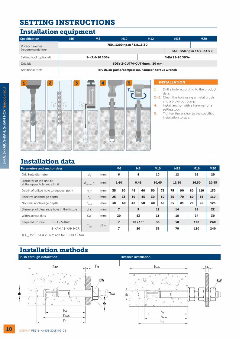
Installation equipmentSpecification M6 M8 M10 M12 M16 M20
Rotary hammer (recommendation)
750...1200 r.p.m / 1.8…3.3 J
360…550 r.p.m / 4.9…11.5 J
Setting tool (optional) S-KA 6-10 SDS+ S-KA 12-20 SDS+
Drill bit SDS+ 2-CUT/4-CUT 6mm…20 mm
Additional tools brush, air pump/compressor, hammer, torque wrench
Installation methodsPush-through installation Distance installation
INSTALLATION
1. Drill a hole according to the product data.
2.-3. Clean the hole using a metal brush and a blow-out pump.
4. Install anchor with a hammer or a setting tool.
5. Tighten the anchor to the specified installation torque.
Installation data Parameters and anchor sizes M6 M8 M10 M12 M16 M20
Drill hole diameter d0
[mm] 6 8 10 12 16 20
Diameter of the drill bit at the upper tolerance limit
dcut,max
≤ [mm] 6,40 8,45 10,45 12,50 16,50 20,55
Depth of drilled hole to deepest point h1 ≥ [mm] 35 50 45 60 50 75 75 90 80 110 130
Effective anchorage depth hef
[mm] 25 35 30 45 30 60 55 70 60 85 110
Nominal anchorage depth hnom
[mm] 30 40 40 50 40 68 65 81 70 96 125
Diameter of clearance hole in the fixture df ≤ [mm] 7 9 12 14 18 22
Width across flats SW [mm] 20 13 16 18 24 30
Required torque S-KA / S-KAKT
inst[Nm]
7 20 / 151) 35 50 120 240
S-KAH / S-KAH HCR 7 20 35 70 120 240
1) Tinst
for S-KA is 20 Nm and for S-KAK 15 Nm
S-KA
Through installation
h1
d0
hnom
hef
hmin Tfix
SW
Tinst
df
SORMAT PDS-S-KA-EN-2018-05-03
S-K
A, S
-KA
K, S
-KA
H, S
-KA
H H
CR
TH
RO
UG
H B
OLT
10
SETTING INSTRUCTIONS

Minimum thickness of concrete member, spacing and edge distanceCracked and non-cracked concrete M6 M8 M10 M12 M16 M20
Effective anchorage depth hef
[mm] 25 35 30 45 30 60 55 70 60 85 110
Minimum thickness of base material
hmin
[mm] 50 60 60 100 65 120 100 140 110 170 180
Minimum spacings
min[mm] 120 120 160 50 200 55 240 60 320 70 400
c ≥ [mm] 90 90 120 50 150 80 180 90 240 120 300
Minimum edge distancec
min[mm] 90 90 120 50 150 50 180 55 240 85 300
s ≥ [mm] 120 120 160 50 200 100 240 145 320 150 400
Critical spacing for splitting failure and concrete cone failure (in case characteristic loading affects)
scr,sp
[mm] - - - 180 - 240 - 280 - 340 -
scr,N
[mm] 120 120 160 135 200 180 240 210 320 255 400
Critical edge distance for splitting failure and concrete cone failure (in case characteristic loading affects)
ccr,sp
[mm] - - - 90 - 120 - 140 - 170 -
ccr,N
[mm] 90 90 120 68 150 90 180 105 240 128 300REVISION HISTORYREV DESCRIPTION Date/By Approved by
SCALE
DRAWNCHECKED
NAMEjuhman
DATE17.05.2017
TITLE
SIZE
A3
DRAWINGNUMBER
REV
S-KA_TDS.dft
WEIGHT:
SHEET 1 OF 1
Cop
yrig
ht b
y So
rmat
Oy.
All
right
s re
serv
ed. R
efer
to p
rote
ctio
n no
tice
ISO
160
16.
1:2
0,000 kg
MATERIALGRADE Error: No reference
Error: No referenceSTRENGTH
COATING Error: No reference Error: No reference
FILE NAME
REPLACES
THICKNESS > Error: No referenceSURFACE HARDNESS Error: No reference
Error: No referenceMAT. INFO1 Error: No referenceMAT. INFO2
ADD. INFO1 :
ADD. INFO2 :
Dimensionswithout tolerancein acc. with DIN
7168, middle
STANDARDµm
SORMAT SORMAT PDS-S-KA-EN-2018-05-03
S-K
A, S
-KA
K, S
-KA
H, S
-KA
H H
CR
TH
RO
UG
H B
OLT
11
Setting tool S-KA TOOL SDS+ Hammering tool to make through bolt installation quicker and smoother
• Original Sormat through bolts setting tool with designed head that does not damage the head of the anchor and keep the head from slipping.
• Besides ensuring most efficient and safe through bolt installation in general, the setting tool also significantly saves time and energy in serial installation.
• Compatible with all rotary hammer machines with SDS+ chuck.

DELIVERY PROGRAM S-KA S-KAKS-KAH
A4S-KAH HCR
S-KAR A2
HHA A2
Thread size Type T
fixLength Zinc Hot dip
Stainless A4 HCR A2 A2
M6
6/15x65 15 mm 65 mm • • •6/50x100 50 mm 100 mm • •
6x40 2 mm 40 mm • • •
M8
8/10x72 10 mm 72 mm • • • •8/30x92 30 mm 92 mm • • •8/50x112 50 mm 112 mm • • •8/85x147 85 mm 147 mm • •
8x50 2 mm 52 mm • • •8x105x144 144 mm •8x205x244 244 mm •
8x200 130 mm 200 mm •8x240 170 mm 240 mm •8x300 230 mm 300 mm •
M10
10/10x92 10 mm 92 mm • • • •10/20x102 20 mm 102 mm • • •10/30x112 30 mm 112 mm • • • •10/50x132 50 mm 132 mm • • •10/80x162 80 mm 162 mm • •
10x60 3 mm 62 mm • • •
M12
12/5x103 5 mm 103 mm • • •12/20x118 20 mm 118 mm • • •12/30x128 30 mm 128 mm • • •12/50x148 50 mm 148 mm • • •12/65x163 65 mm 163 mm • • •12/80x178 80 mm 178 mm • •12/155x253 155 mm 253 mm • •
12x75 75 mm •12x85 3 mm 85 mm •
M16
16/5x123 5 mm 123 mm • • •16/20x138 20 mm 138 mm • • •16/50x168 50 mm 168 mm • • •16/60x178 60 mm 178 mm • • •16/95x213 95 mm 213 mm • •
16x90 3 mm 90 mm •
M20
20/20x170 20 mm 170 mm • • •20/70x220 70 mm 220 mm • • •20/130x280 130 mm 280 mm • •
• ETA approved
• No ETA
SORMAT PDS-S-KA-EN-2018-05-03
S-K
A, S
-KA
K, S
-KA
H, S
-KA
H H
CR
TH
RO
UG
H B
OLT
12
www.sormat.com
facebook.com/sormat
youtube.com/sormatfixing
THROUGH BOLTS