s interstate 90 jones county - south dakota … · design specifications: aashto standard...
TRANSCRIPT
S.D.
R.
31 32 33
78 9 10
15161718F
AS
90
3.0
241 ST
242 ST
243 ST
244 ST
256
AV
E
255 S
T
254
AV
E
248
T 2 S
R 26 E
4 3TO MURDO
TO BELVIDERE
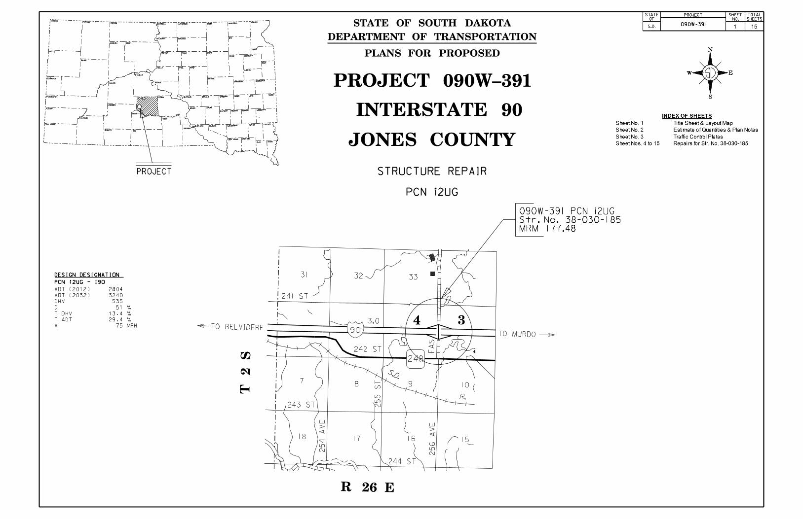
Str. No. 38-030-185MRM 177.48
090W-391 PCN i2UG
CORSON
JONESPENNINGTON
PROJECT SHEET
NO.
TOTAL
SHEETS
STATE
OF
S.D.090W-391
CLAY UNION
BON HOMME YANKTON
CHARLES MIX HUTCHINSON TURNER LINCOLN
MINNEHAHAMcCOOKHANSONDAVISON
BUFFALO JERAULD SANBORN MINER LAKEMOODY
BROOKINGSKINGSBURY
HYDE HAND
HUGHES
POTTER FAULK SPINK
CODINGTON
HAMLIN
DEUL
EDMUNDS
CAMPBELL McPHERSON MARSHALL ROBERTS
HARDING
ZIEBACH DEWEY
MEADE
BUTTE
HAAKON
JACKSON
LYMAN
TRIPP
BENNETT
CUSTER
FALL RIVERDOUGLAS
AURORABRULE
BEADLE
SULLY
CLARK
GRANT
DAYWALWORTH
BROWN
PERKINS
LAWRENCE
STANLEY
GREGORY
MELLETTE
TODD
SHANNON
PROJECT
DESIGN DESIGNATION
PCN i2UG - I90
V 75 MPH
T ADT 29.4 %
T DHV 13.4 %
D 51 %
DHV 535
ADT (2032) 3240
ADT (2012) 2804
1 15
N
S
EW
DEPARTMENT OF TRANSPORTATION
PLANS FOR PROPOSED
STATE OF SOUTH DAKOTA
STRUCTURE REPAIR
INTERSTATE 90
JONES COUNTY
PCN i2UG
PROJECT 090W-391
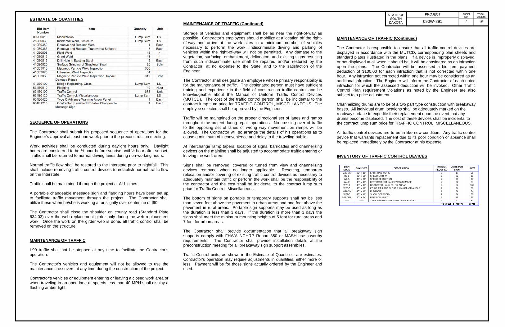
ESTIMATE OF QUANTITIES
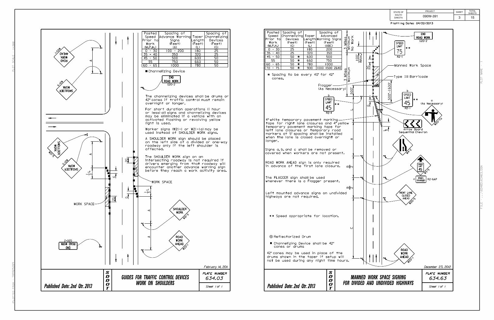
SEQUENCE OF OPERATIONS The Contractor shall submit his proposed sequence of operations for the Engineer’s approval at least one week prior to the preconstruction meeting. Work activities shall be conducted during daylight hours only. Daylight hours are considered to be ½ hour before sunrise until ½ hour after sunset. Traffic shall be returned to normal driving lanes during non-working hours. Normal traffic flow shall be restored to the Interstate prior to nightfall. This shall include removing traffic control devices to establish normal traffic flow on the Interstate. Traffic shall be maintained through the project at ALL times. A portable changeable message sign and flagging hours have been set up to facilitate traffic movement through the project. The Contractor shall utilize these when he/she is working at or slightly over centerline of I90. The Contractor shall close the shoulder on county road (Standard Plate 634.03) over the web replacement girder only during the web replacement work. Once the work on the girder web is done, all traffic control shall be removed on the structure. MAINTENANCE OF TRAFFIC I-90 traffic shall not be stopped at any time to facilitate the Contractor’s operation. The Contractor's vehicles and equipment will not be allowed to use the maintenance crossovers at any time during the construction of the project. Contractor’s vehicles or equipment entering or leaving a closed work area or when traveling in an open lane at speeds less than 40 MPH shall display a flashing amber light.
MAINTENANCE OF TRAFFIC (Continued) Storage of vehicles and equipment shall be as near the right-of-way as possible. Contractor’s employees should mobilize at a location off the right-of-way and arrive at the work sites in a minimum number of vehicles necessary to perform the work. Indiscriminate driving and parking of vehicles within the right-of-way will not be permitted. Any damage to the vegetation, surfacing, embankment, delineators and existing signs resulting from such indiscriminate use shall be repaired and/or restored by the Contractor, at no expense to the State, and to the satisfaction of the Engineer. The Contractor shall designate an employee whose primary responsibility is for the maintenance of traffic. The designated person must have sufficient training and experience in the field of construction traffic control and be knowledgeable about the Manual of Uniform Traffic Control Devices (MUTCD). The cost of the traffic control person shall be incidental to the contract lump sum price for TRAFFIC CONTROL, MISCELLANEOUS. The employee selected shall be approved by the Engineer. Traffic will be maintained on the proper directional set of lanes and ramps throughout the project during repair operations. No crossing over of traffic to the opposing set of lanes or wrong way movement on ramps will be allowed. The Contractor will so arrange the details of his operations as to cause a minimum of inconvenience and delay to the traveling public. At interchange ramp tapers, location of signs, barricades and channelizing devices on the mainline shall be adjusted to accommodate traffic entering or leaving the work area. Signs shall be removed, covered or turned from view and channelizing devices removed when no longer applicable. Resetting, temporary relocation and/or covering of existing traffic control devices as necessary to adequately maintain traffic or perform the work shall be the responsibility of the contractor and the cost shall be incidental to the contract lump sum price for Traffic Control, Miscellaneous. The bottom of signs on portable or temporary supports shall not be less than seven feet above the pavement in urban areas and one foot above the pavement in rural areas. Portable sign supports may be used as long as the duration is less than 3 days. If the duration is more than 3 days the signs shall meet the minimum mounting heights of 5 foot for rural areas and 7 foot for urban areas. The Contractor shall provide documentation that all breakaway sign supports comply with FHWA NCHRP Report 350 or MASH crash-worthy requirements. The Contractor shall provide installation details at the preconstruction meeting for all breakaway sign support assemblies. Traffic Control units, as shown in the Estimate of Quantities, are estimates. Contractor’s operation may require adjustments in quantities, either more or less. Payment will be for those signs actually ordered by the Engineer and used.
MAINTENANCE OF TRAFFIC (Continued) The Contractor is responsible to ensure that all traffic control devices are displayed in accordance with the MUTCD, corresponding plan sheets and standard plates illustrated in the plans. If a device is improperly displayed, or not displayed at all when it should be, it will be considered as an infraction upon the plans. The Contractor will be assessed a bid item payment deduction of $100.00 for each infraction that is not corrected within one hour. Any infraction not corrected within one hour may be considered as an additional infraction. The Engineer will inform the Contractor of each noted infraction for which the assessed deduction will be invoked. Other Traffic Control Plan requirement violations as noted by the Engineer are also subject to a price adjustment. Channelizing drums are to be of a two part type construction with breakaway bases. All individual drum locations shall be adequately marked on the roadway surface to expedite their replacement upon the event that any drums become displaced. The cost of these devices shall be incidental to the contract lump sum price for TRAFFIC CONTROL, MISCELLANEOUS. All traffic control devices are to be in like new condition. Any traffic control device that warrants replacement due to its poor condition or absence shall be replaced immediately by the Contractor at his expense. INVENTORY OF TRAFFIC CONTROL DEVICES
SIGN CODE SIGN SIZE DESCRIPTION NUMBER
REQUIREDUNITS PER
SIGN UNITS
G20-2A 36'' x 18'' END ROAD WORK 3 17 51R2-1 30'' x 36'' SPEED LIMIT ## 3 23 69W3-5 48'' x 48'' SPEED REDUCTION 2 34 68W4-2 48'' x 48'' LEFT OR RIGHT LANE ENDS (SYMBOL) 2 34 68W20-1 48'' x 48'' ROAD WORK #### FT. OR AHEAD 4 34 136W20-5 48'' x 48'' LT. OR RT. LANE CLOSED #### FT. OR AHEAD 2 34 68
W20-7a 48'' x 48'' FLAGGER 1 34 34W21-5 48'' x 48'' SHOULDER WORK 2 34 68
SPECIAL 30'' x 24'' FINES DOUBLED 2 18 36***** ***** TYPE III BARRICADE - 8 FT. SINGLE SIDED 2 40 80
TOTAL UNITS 678
PROJECT STATE OF SOUTH
DAKOTA 090W-391
SHEET NO.
2 15
TOTAL SHEETS
DAKOTA
SOUTH
STATE OFPROJECT
SHEETSHEETS
TOTAL
3 15090W-391
04/22/2013Plotting Date:
trpr25289
1:200
1
Plotted
Fro
m -
Plot
Scale -
File - ...\63403,63463.dgn
Plot
Na
me -
4 15
PROJECTSTATEOF
S.D. 090W-391
SHEETNO.
TOTALSHEETS
CHECKED BY:
KH
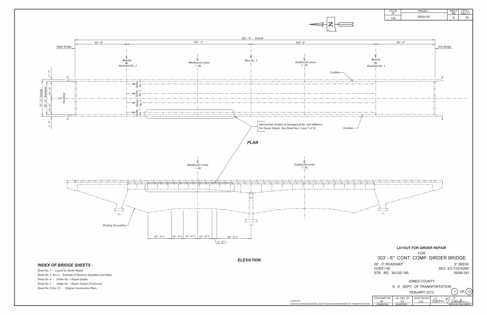
ESTIMATE OF STRUCTURE QUANTIES AND NOTESFOR
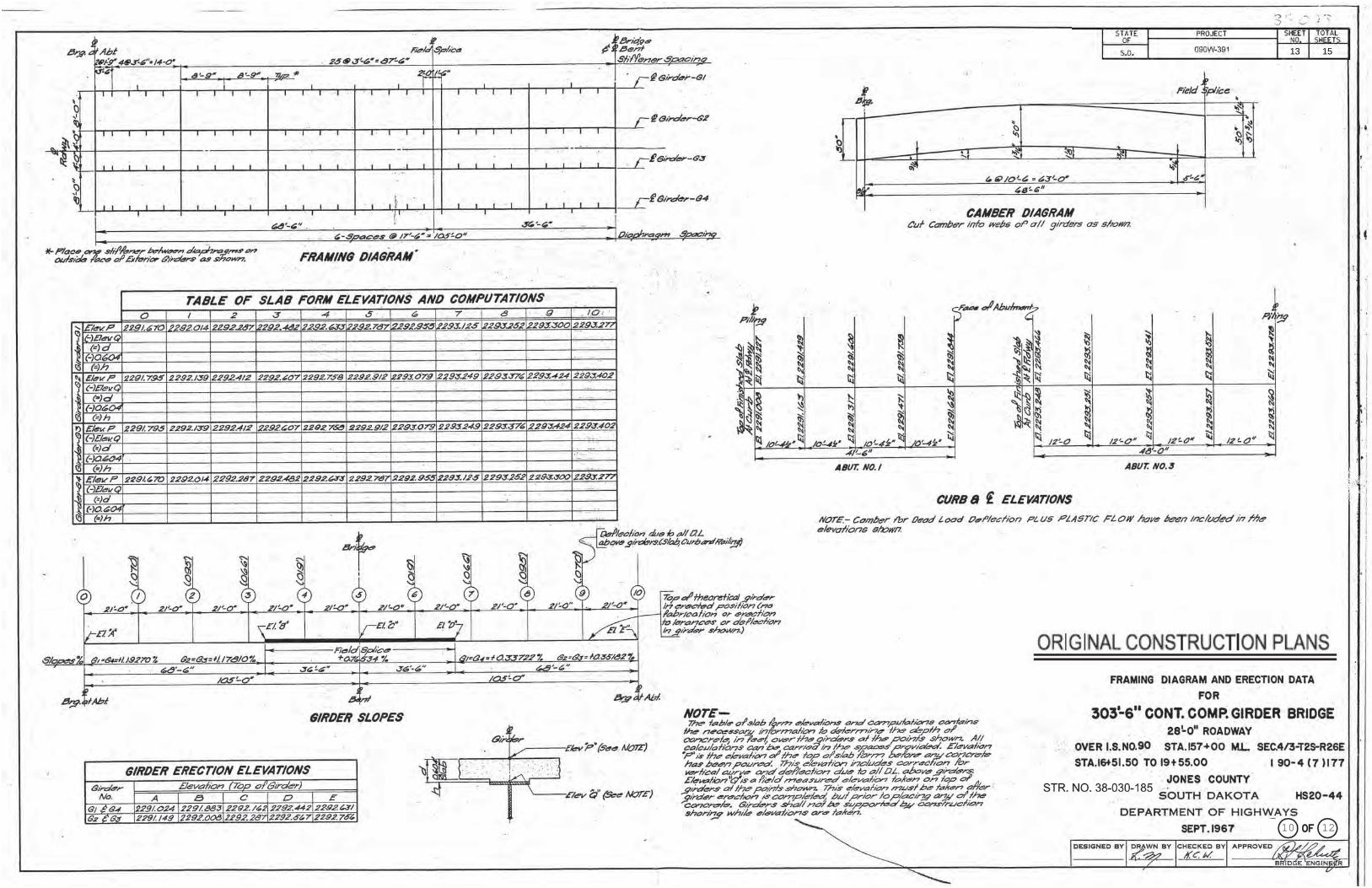
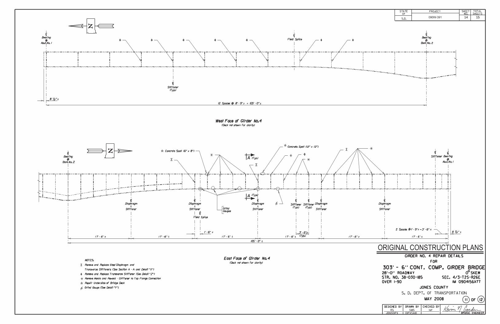
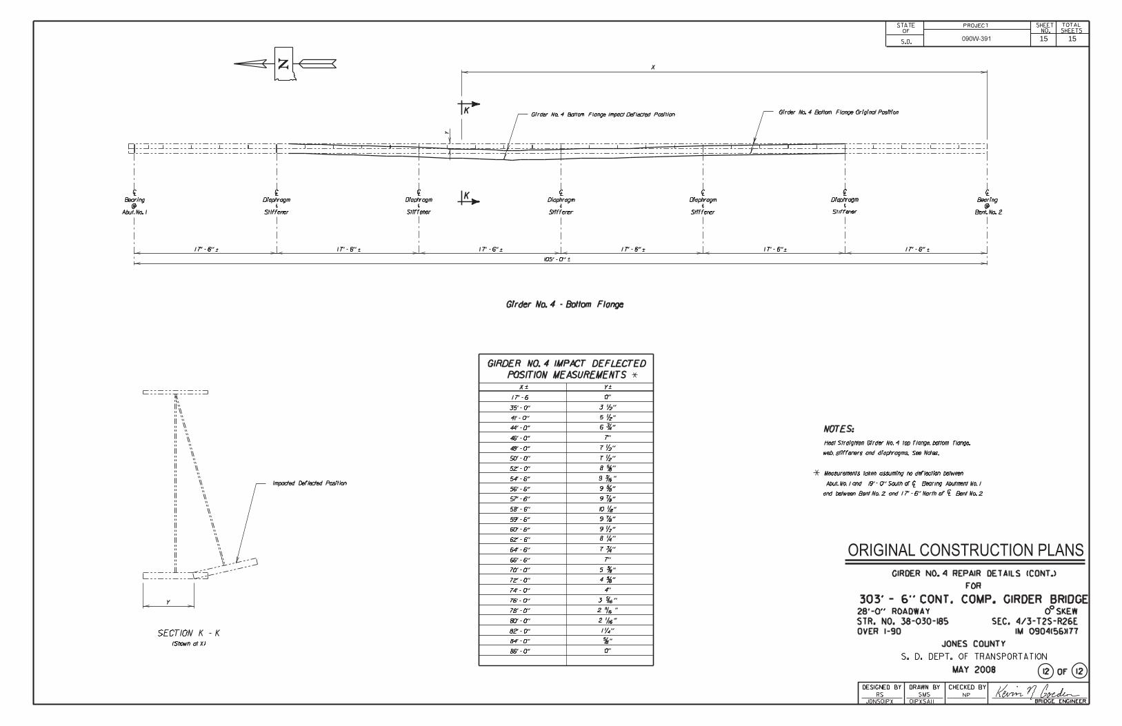
303’ – 6” CONT. COMP. GIRDER BRIDGE
Str. No. 38-030-185
FEBRUARY 2013DESIGNED BY:
NPJONSI2UG
DRAWN BY:
NPI2UGNOTA BRIDGE ENGINEER
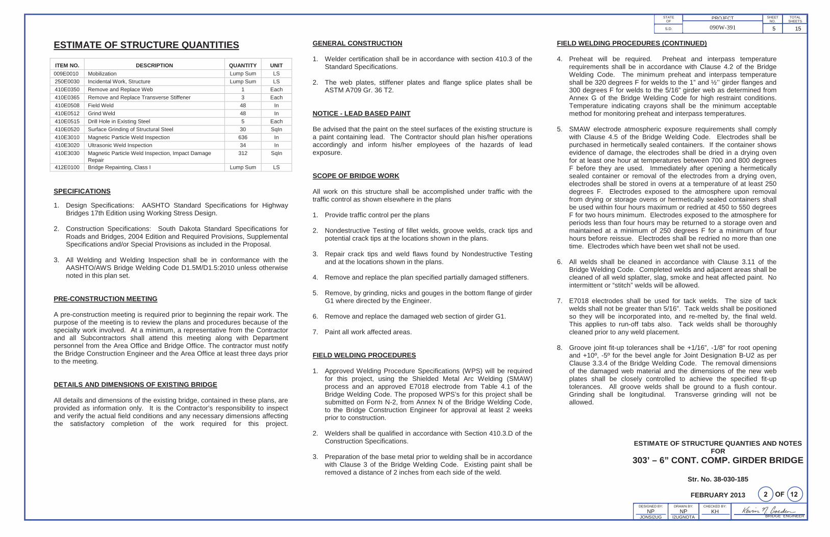
ESTIMATE OF STRUCTURE QUANTITIES
ITEM NO. DESCRIPTION QUANTITY UNIT009E0010 Mobilization Lump Sum LS250E0030 Incidental Work, Structure Lump Sum LS410E0350 Remove and Replace Web 1 Each410E0365 Remove and Replace Transverse Stiffener 3 Each410E0508 Field Weld 48 In410E0512 Grind Weld 48 In410E0515 Drill Hole in Existing Steel 5 Each410E0520 Surface Grinding of Structural Steel 30 SqIn410E3010 Magnetic Particle Weld Inspection 636 In410E3020 Ultrasonic Weld Inspection 34 In410E3030 Magnetic Particle Weld Inspection, Impact Damage
Repair312 SqIn
412E0100 Bridge Repainting, Class I Lump Sum LS
SPECIFICATIONS
1. Design Specifications: AASHTO Standard Specifications for Highway Bridges 17th Edition using Working Stress Design.
2. Construction Specifications: South Dakota Standard Specifications for Roads and Bridges, 2004 Edition and Required Provisions, Supplemental Specifications and/or Special Provisions as included in the Proposal.
3. All Welding and Welding Inspection shall be in conformance with the AASHTO/AWS Bridge Welding Code D1.5M/D1.5:2010 unless otherwise noted in this plan set.
PRE-CONSTRUCTION MEETING
A pre-construction meeting is required prior to beginning the repair work. The purpose of the meeting is to review the plans and procedures because of the specialty work involved. At a minimum, a representative from the Contractor and all Subcontractors shall attend this meeting along with Department personnel from the Area Office and Bridge Office. The contractor must notify the Bridge Construction Engineer and the Area Office at least three days prior to the meeting.
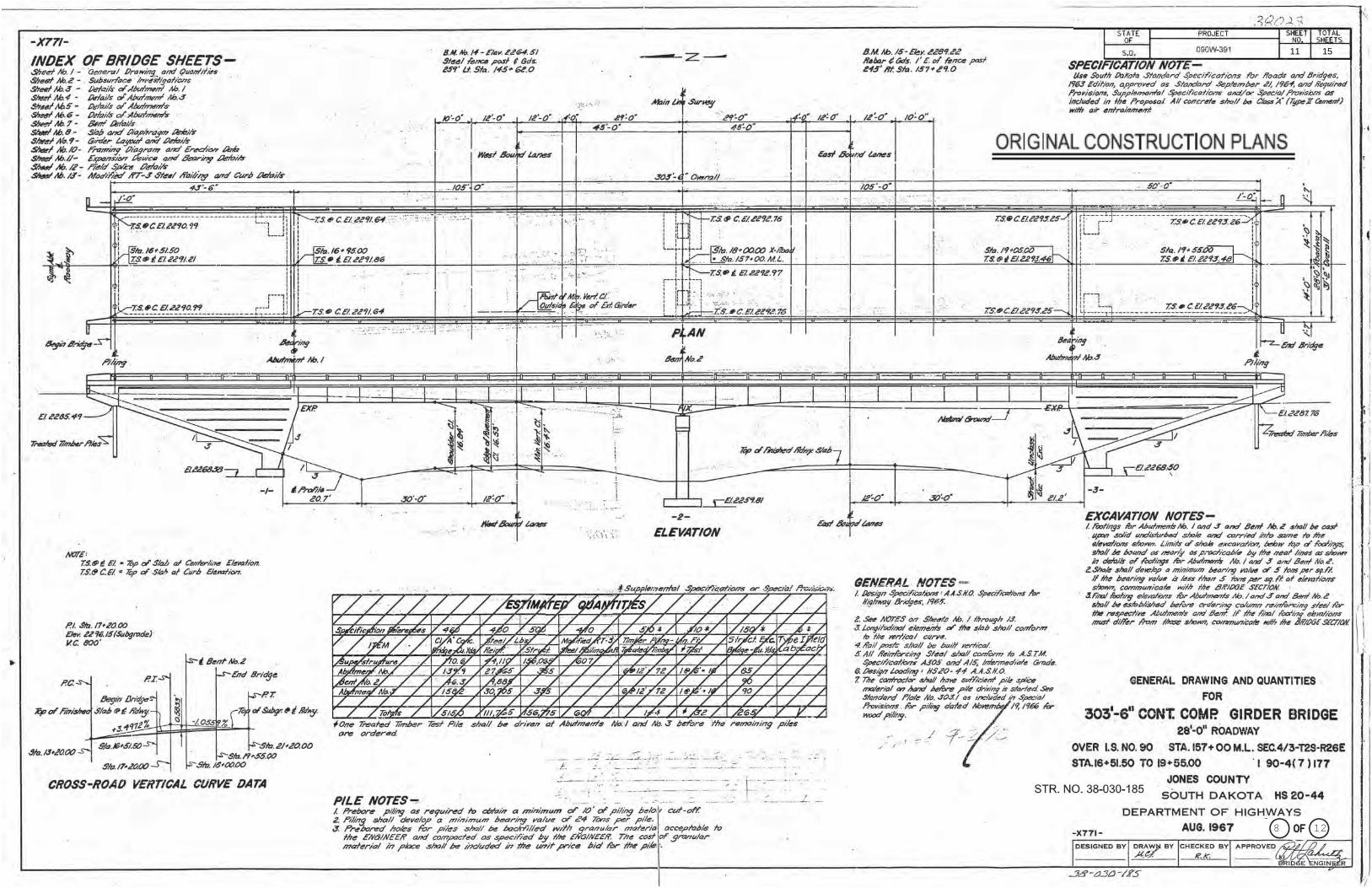
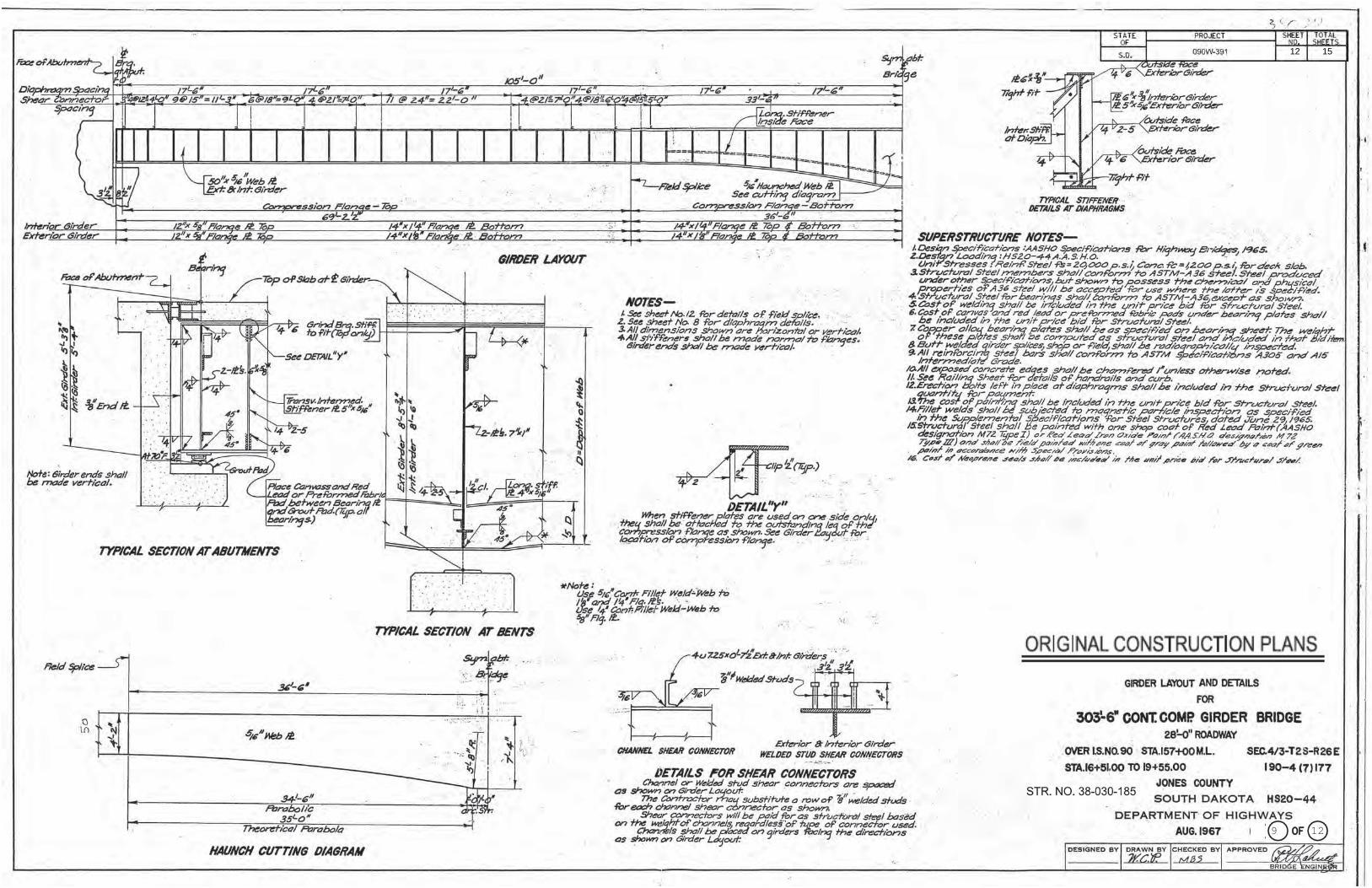
DETAILS AND DIMENSIONS OF EXISTING BRIDGE
All details and dimensions of the existing bridge, contained in these plans, are provided as information only. It is the Contractor’s responsibility to inspect and verify the actual field conditions and any necessary dimensions affecting the satisfactory completion of the work required for this project.
GENERAL CONSTRUCTION
1. Welder certification shall be in accordance with section 410.3 of the Standard Specifications.
2. The web plates, stiffener plates and flange splice plates shall be ASTM A709 Gr. 36 T2.
NOTICE - LEAD BASED PAINT
Be advised that the paint on the steel surfaces of the existing structure is a paint containing lead. The Contractor should plan his/her operations accordingly and inform his/her employees of the hazards of lead exposure.
SCOPE OF BRIDGE WORK
All work on this structure shall be accomplished under traffic with the traffic control as shown elsewhere in the plans
1. Provide traffic control per the plans
2. Nondestructive Testing of fillet welds, groove welds, crack tips and potential crack tips at the locations shown in the plans.
3. Repair crack tips and weld flaws found by Nondestructive Testingand at the locations shown in the plans.
4. Remove and replace the plan specified partially damaged stiffeners.
5. Remove, by grinding, nicks and gouges in the bottom flange of girder G1 where directed by the Engineer.
6. Remove and replace the damaged web section of girder G1.
7. Paint all work affected areas.
FIELD WELDING PROCEDURES
1. Approved Welding Procedure Specifications (WPS) will be required for this project, using the Shielded Metal Arc Welding (SMAW) process and an approved E7018 electrode from Table 4.1 of the Bridge Welding Code. The proposed WPS’s for this project shall be submitted on Form N-2, from Annex N of the Bridge Welding Code, to the Bridge Construction Engineer for approval at least 2 weeks prior to construction.
2. Welders shall be qualified in accordance with Section 410.3.D of the Construction Specifications.
3. Preparation of the base metal prior to welding shall be in accordance with Clause 3 of the Bridge Welding Code. Existing paint shall be removed a distance of 2 inches from each side of the weld.
FIELD WELDING PROCEDURES (CONTINUED)
4. Preheat will be required. Preheat and interpass temperature requirements shall be in accordance with Clause 4.2 of the Bridge Welding Code. The minimum preheat and interpass temperature shall be 320 degrees F for welds to the 1” and ½’’ girder flanges and 300 degrees F for welds to the 5/16” girder web as determined from Annex G of the Bridge Welding Code for high restraint conditions. Temperature indicating crayons shall be the minimum acceptable method for monitoring preheat and interpass temperatures.
5. SMAW electrode atmospheric exposure requirements shall comply with Clause 4.5 of the Bridge Welding Code. Electrodes shall be purchased in hermetically sealed containers. If the container shows evidence of damage, the electrodes shall be dried in a drying oven for at least one hour at temperatures between 700 and 800 degrees F before they are used. Immediately after opening a hermetically sealed container or removal of the electrodes from a drying oven, electrodes shall be stored in ovens at a temperature of at least 250 degrees F. Electrodes exposed to the atmosphere upon removal from drying or storage ovens or hermetically sealed containers shall be used within four hours maximum or redried at 450 to 550 degrees F for two hours minimum. Electrodes exposed to the atmosphere for periods less than four hours may be returned to a storage oven and maintained at a minimum of 250 degrees F for a minimum of four hours before reissue. Electrodes shall be redried no more than one time. Electrodes which have been wet shall not be used.
6. All welds shall be cleaned in accordance with Clause 3.11 of the Bridge Welding Code. Completed welds and adjacent areas shall be cleaned of all weld splatter, slag, smoke and heat affected paint. No intermittent or “stitch” welds will be allowed.
7. E7018 electrodes shall be used for tack welds. The size of tack welds shall not be greater than 5/16”. Tack welds shall be positioned so they will be incorporated into, and re-melted by, the final weld. This applies to run-off tabs also. Tack welds shall be thoroughlycleaned prior to any weld placement.
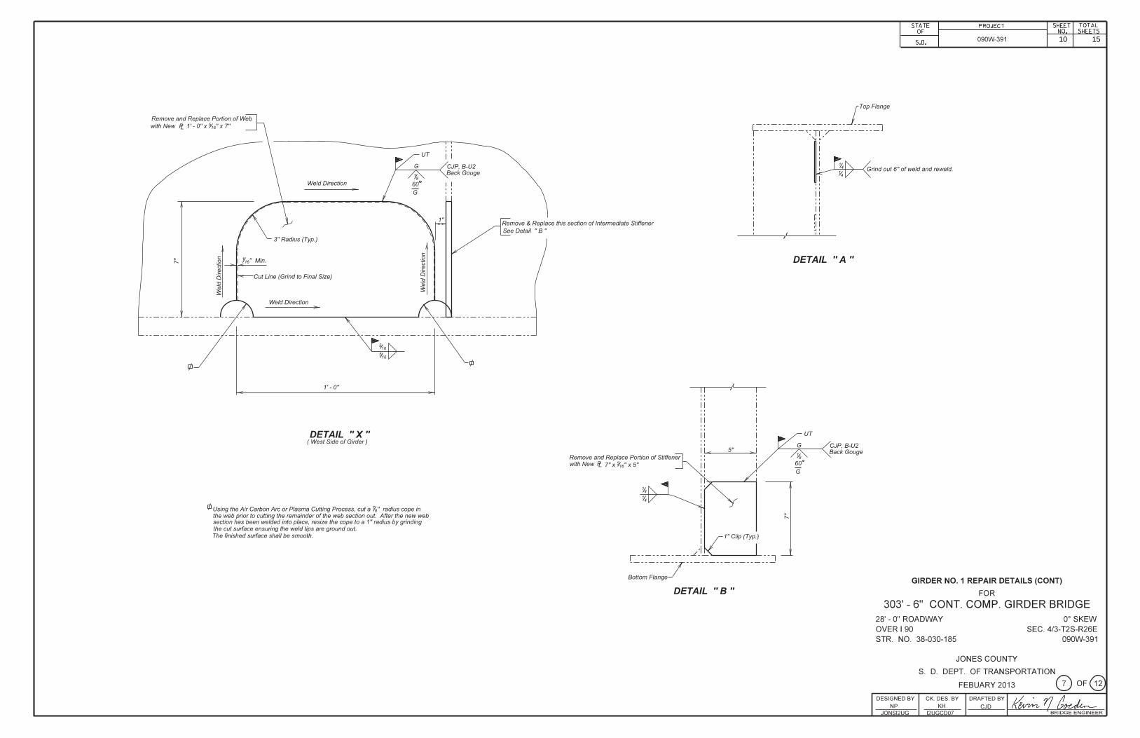
8. Groove joint fit-up tolerances shall be +1/16”, -1/8” for root opening and +10º, -5º for the bevel angle for Joint Designation B-U2 as per Clause 3.3.4 of the Bridge Welding Code. The removal dimensions of the damaged web material and the dimensions of the new web plates shall be closely controlled to achieve the specified fit-up tolerances. All groove welds shall be ground to a flush contour. Grinding shall be longitudinal. Transverse grinding will not be allowed.
5 15
BRIDGE ENGINEER
PROJECTSTATEOF
S.D. 090W-391
SHEETNO.
TOTALSHEETS
CHECKED BY:
KH
NOTES (CONTINUED)FOR
303’ – 6” CONT. COMP. GIRDER BRIDGE
Str. No. 38-030-185
FEBRUARY 2013DESIGNED BY:
NPJONSI2UG
DRAWN BY:
NPI2UGNOTA
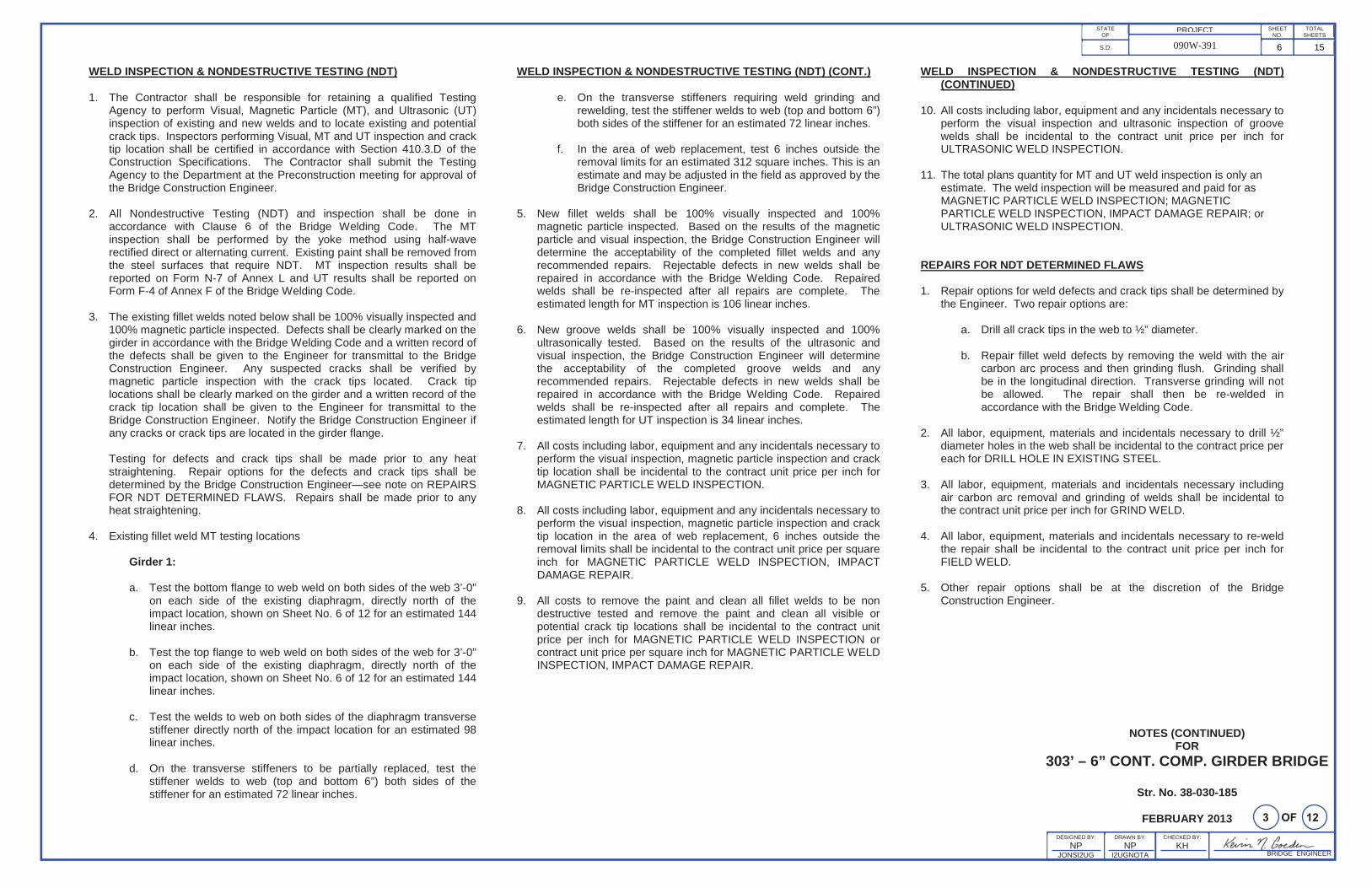
WELD INSPECTION & NONDESTRUCTIVE TESTING (NDT)
1. The Contractor shall be responsible for retaining a qualified Testing Agency to perform Visual, Magnetic Particle (MT), and Ultrasonic (UT) inspection of existing and new welds and to locate existing and potential crack tips. Inspectors performing Visual, MT and UT inspection and crack tip location shall be certified in accordance with Section 410.3.D of the Construction Specifications. The Contractor shall submit the Testing Agency to the Department at the Preconstruction meeting for approval of the Bridge Construction Engineer.
2. All Nondestructive Testing (NDT) and inspection shall be done in accordance with Clause 6 of the Bridge Welding Code. The MT inspection shall be performed by the yoke method using half-wave rectified direct or alternating current. Existing paint shall be removed from the steel surfaces that require NDT. MT inspection results shall be reported on Form N-7 of Annex L and UT results shall be reported on Form F-4 of Annex F of the Bridge Welding Code.
3. The existing fillet welds noted below shall be 100% visually inspected and 100% magnetic particle inspected. Defects shall be clearly marked on the girder in accordance with the Bridge Welding Code and a written record ofthe defects shall be given to the Engineer for transmittal to the Bridge Construction Engineer. Any suspected cracks shall be verified by magnetic particle inspection with the crack tips located. Crack tip locations shall be clearly marked on the girder and a written record of the crack tip location shall be given to the Engineer for transmittal to the Bridge Construction Engineer. Notify the Bridge Construction Engineer if any cracks or crack tips are located in the girder flange.
Testing for defects and crack tips shall be made prior to any heat straightening. Repair options for the defects and crack tips shall be determined by the Bridge Construction Engineer—see note on REPAIRS FOR NDT DETERMINED FLAWS. Repairs shall be made prior to any heat straightening.
4. Existing fillet weld MT testing locations
Girder 1:
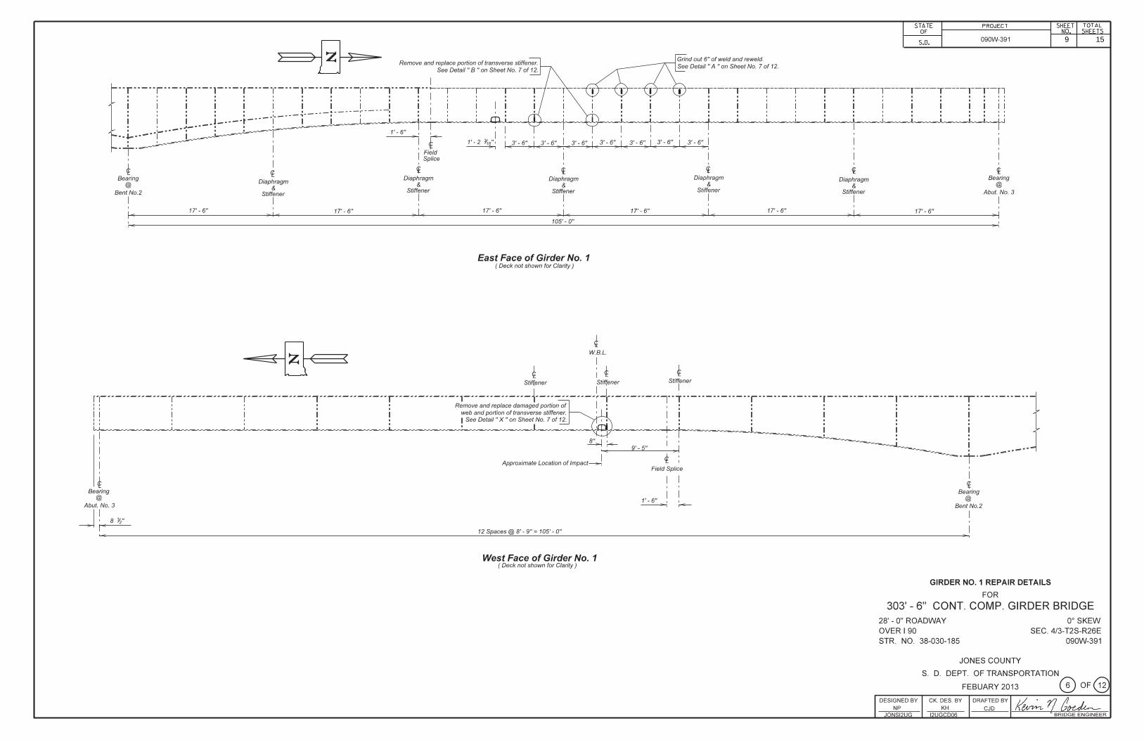
a. Test the bottom flange to web weld on both sides of the web 3’-0” on each side of the existing diaphragm, directly north of the impact location, shown on Sheet No. 6 of 12 for an estimated 144linear inches.
b. Test the top flange to web weld on both sides of the web for 3’-0” on each side of the existing diaphragm, directly north of the impact location, shown on Sheet No. 6 of 12 for an estimated 144linear inches.
c. Test the welds to web on both sides of the diaphragm transverse stiffener directly north of the impact location for an estimated 98linear inches.
d. On the transverse stiffeners to be partially replaced, test the stiffener welds to web (top and bottom 6”) both sides of the stiffener for an estimated 72 linear inches.
WELD INSPECTION & NONDESTRUCTIVE TESTING (NDT) (CONT.)
e. On the transverse stiffeners requiring weld grinding and rewelding, test the stiffener welds to web (top and bottom 6”) both sides of the stiffener for an estimated 72 linear inches.
f. In the area of web replacement, test 6 inches outside the removal limits for an estimated 312 square inches. This is an estimate and may be adjusted in the field as approved by the Bridge Construction Engineer.
5. New fillet welds shall be 100% visually inspected and 100% magnetic particle inspected. Based on the results of the magnetic particle and visual inspection, the Bridge Construction Engineer will determine the acceptability of the completed fillet welds and any recommended repairs. Rejectable defects in new welds shall be repaired in accordance with the Bridge Welding Code. Repaired welds shall be re-inspected after all repairs are complete. The estimated length for MT inspection is 106 linear inches.
6. New groove welds shall be 100% visually inspected and 100% ultrasonically tested. Based on the results of the ultrasonic and visual inspection, the Bridge Construction Engineer will determine the acceptability of the completed groove welds and any recommended repairs. Rejectable defects in new welds shall be repaired in accordance with the Bridge Welding Code. Repaired welds shall be re-inspected after all repairs and complete. The estimated length for UT inspection is 34 linear inches.
7. All costs including labor, equipment and any incidentals necessary to perform the visual inspection, magnetic particle inspection and crack tip location shall be incidental to the contract unit price per inch for MAGNETIC PARTICLE WELD INSPECTION.
8. All costs including labor, equipment and any incidentals necessary to perform the visual inspection, magnetic particle inspection and crack tip location in the area of web replacement, 6 inches outside the removal limits shall be incidental to the contract unit price per square inch for MAGNETIC PARTICLE WELD INSPECTION, IMPACT DAMAGE REPAIR.
9. All costs to remove the paint and clean all fillet welds to be non destructive tested and remove the paint and clean all visible or potential crack tip locations shall be incidental to the contract unit price per inch for MAGNETIC PARTICLE WELD INSPECTION or contract unit price per square inch for MAGNETIC PARTICLE WELD INSPECTION, IMPACT DAMAGE REPAIR.
WELD INSPECTION & NONDESTRUCTIVE TESTING (NDT) (CONTINUED)
10. All costs including labor, equipment and any incidentals necessary to perform the visual inspection and ultrasonic inspection of groove welds shall be incidental to the contract unit price per inch for ULTRASONIC WELD INSPECTION.
11. The total plans quantity for MT and UT weld inspection is only an estimate. The weld inspection will be measured and paid for as MAGNETIC PARTICLE WELD INSPECTION; MAGNETIC PARTICLE WELD INSPECTION, IMPACT DAMAGE REPAIR; or ULTRASONIC WELD INSPECTION.
REPAIRS FOR NDT DETERMINED FLAWS
1. Repair options for weld defects and crack tips shall be determined by the Engineer. Two repair options are:
a. Drill all crack tips in the web to ½” diameter.
b. Repair fillet weld defects by removing the weld with the air carbon arc process and then grinding flush. Grinding shall be in the longitudinal direction. Transverse grinding will not be allowed. The repair shall then be re-welded in accordance with the Bridge Welding Code.
2. All labor, equipment, materials and incidentals necessary to drill ½” diameter holes in the web shall be incidental to the contract price per each for DRILL HOLE IN EXISTING STEEL.
3. All labor, equipment, materials and incidentals necessary including air carbon arc removal and grinding of welds shall be incidental to the contract unit price per inch for GRIND WELD.
4. All labor, equipment, materials and incidentals necessary to re-weld the repair shall be incidental to the contract unit price per inch for FIELD WELD.
5. Other repair options shall be at the discretion of the Bridge Construction Engineer.
6 15
BRIDGE ENGINEER
PROJECTSTATEOF
S.D. 090W-391
SHEETNO.
TOTALSHEETS
CHECKED BY:
KH
NOTES (CONTINUED)FOR
303’ – 6” CONT. COMP. GIRDER BRIDGE
Str. No. 38-030-185
FEBRUARY 2013DESIGNED BY:
NPJONSI2UG
DRAWN BY:
NPI2UGNOTA
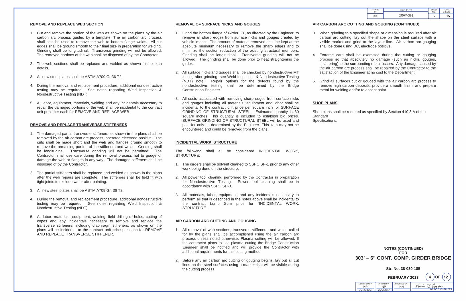
REMOVE AND REPLACE WEB SECTION
1. Cut and remove the portion of the web as shown on the plans by the air carbon arc process guided by a template. The air carbon arc process shall also be used to remove the web to bottom flange welds. All cut edges shall be ground smooth to their final size in preparation for welding. Grinding shall be longitudinal. Transverse grinding will not be allowed. The removed portions of the web shall be disposed of by the Contractor.
2. The web sections shall be replaced and welded as shown in the plan details.
3. All new steel plates shall be ASTM A709 Gr.36 T2.
4. During the removal and replacement procedure, additional nondestructive testing may be required. See notes regarding Weld Inspection & Nondestructive Testing (NDT).
5. All labor, equipment, materials, welding and any incidentals necessary to repair the damaged portions of the web shall be incidental to the contract unit price per each for REMOVE AND REPLACE WEB.
REMOVE AND REPLACE TRANSVERSE STIFFENERS
1. The damaged partial transverse stiffeners as shown in the plans shall be removed by the air carbon arc process, operated electrode positive. The cuts shall be made short and the web and flanges ground smooth to remove the remaining portion of the stiffeners and welds. Grinding shall be longitudinal. Transverse grinding will not be permitted. The Contractor shall use care during the removal process not to gouge or damage the web or flanges in any way. The damaged stiffeners shall be disposed of by the Contractor.
2. The partial stiffeners shall be replaced and welded as shown in the plans after the web repairs are complete. The stiffeners shall be field fit with tight joints to exclude water after painting.
3. All new steel plates shall be ASTM A709 Gr. 36 T2.
4. During the removal and replacement procedure, additional nondestructive testing may be required. See notes regarding Weld Inspection & Nondestructive Testing (NDT).
5. All labor, materials, equipment, welding, field drilling of holes, cutting of copes and any incidentals necessary to remove and replace the transverse stiffeners, including diaphragm stiffeners, as shown on the plans will be incidental to the contract unit price per each for REMOVE AND REPLACE TRANSVERSE STIFFENER.
REMOVAL OF SURFACE NICKS AND GOUGES
1. Grind the bottom flange of Girder G1, as directed by the Engineer, to remove all sharp edges from surface nicks and gouges created by vehicle impact. The amount of material removed shall be kept at the absolute minimum necessary to remove the sharp edges and to minimize the section reduction of the existing structural members. Grinding shall be longitudinal. Transverse grinding will not be allowed. The grinding shall be done prior to heat straightening the girder.
2. All surface nicks and gouges shall be checked by nondestructive MT testing after grinding--see Weld Inspection & Nondestructive Testing (NDT) note. Repair options for the defects found by the nondestructive testing shall be determined by the Bridge Construction Engineer.
3. All costs associated with removing sharp edges from surface nicks and gouges including all materials, equipment and labor shall be incidental to the contract unit price per square inch for SURFACE GRINDING OF STRUCTURAL STEEL. Estimated quantity is 30square inches. This quantity is included to establish bid prices. SURFACE GRINDING OF STRUCTURAL STEEL will be used and paid for only as determined by the Engineer. This item may not be encountered and could be removed from the plans.
INCIDENTAL WORK, STRUCTURE
The following shall all be considered INCIDENTAL WORK, STRUCTURE:
1. The girders shall be solvent cleaned to SSPC SP-1 prior to any other work being done on the structure.
2. All power tool cleaning performed by the Contractor in preparation for Nondestructive Testing. Power tool cleaning shall be in accordance with SSPC SP-3.
3. All materials, labor, equipment, and any incidentals necessary to perform all that is described in the notes above shall be incidental to the contract Lump Sum price for “INCIDENTAL WORK, STRUCTURE.”
AIR CARBON ARC CUTTING AND GOUGING
1. All removal of web sections, transverse stiffeners, and welds called for by the plans shall be accomplished using the air carbon arc process unless noted otherwise. Plasma cutting will be allowed. If the contractor plans to use plasma cutting the Bridge Construction Engineer shall be notified and will provide the Contractor with additional requirements for this cutting method.
2. Before any air carbon arc cutting or gouging begins, lay out all cut lines on the steel surfaces using a marker that will be visible during the cutting process.
AIR CARBON ARC CUTTING AND GOUGING (CONTINUED)
3. When grinding to a specified shape or dimension is required after air carbon arc cutting, lay out the shape on the steel surface with a visible marker and grind to the layout line. Air carbon arc gouging shall be done using DC, electrode positive.
4. Extreme care shall be exercised during the cutting or gouging process so that absolutely no damage (such as nicks, gouges, splattering) to the surrounding metal occurs. Any damage caused by the air carbon arc process shall be repaired by the Contractor to the satisfaction of the Engineer at no cost to the Department.
5. Grind all surfaces cut or gouged with the air carbon arc process to remove high carbon deposits, provide a smooth finish, and prepare metal for welding and/or to accept paint.
SHOP PLANS
Shop plans shall be required as specified by Section 410.3.A of the StandardSpecifications.
7 15
BRIDGE ENGINEER
PROJECTSTATEOF
S.D. 090W-391
SHEETNO.
TOTALSHEETS
CHECKED BY:
KH
NOTES (CONTINUED)FOR
303’ – 6” CONT. COMP. GIRDER BRIDGE
Str. No. 38-030-185
FEBRUARY 2013DESIGNED BY:
NPJONSI2UG
DRAWN BY:
NPI2UGNOTA
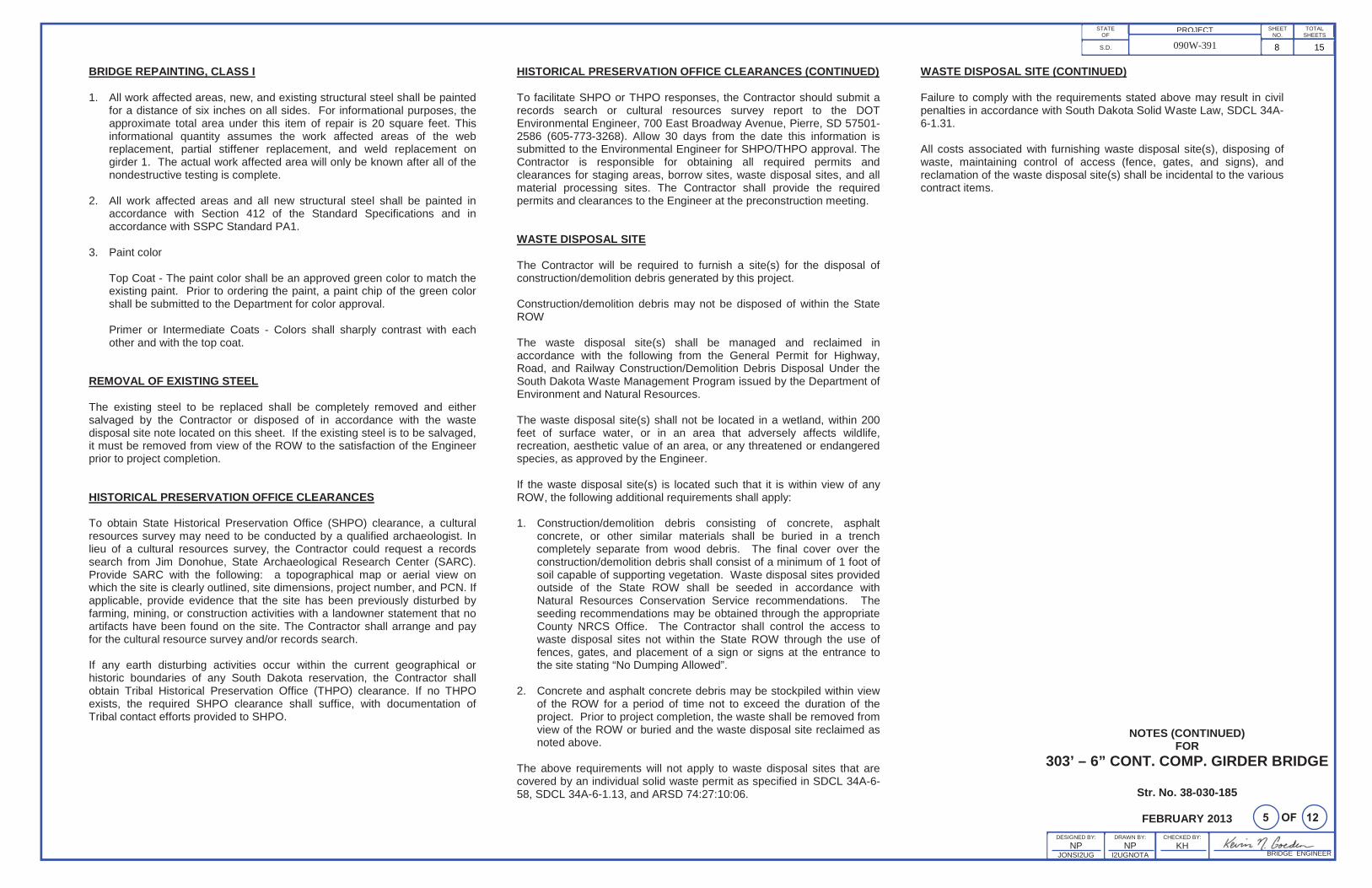
BRIDGE REPAINTING, CLASS I
1. All work affected areas, new, and existing structural steel shall be painted for a distance of six inches on all sides. For informational purposes, the approximate total area under this item of repair is 20 square feet. This informational quantity assumes the work affected areas of the web replacement, partial stiffener replacement, and weld replacement on girder 1. The actual work affected area will only be known after all of the nondestructive testing is complete.
2. All work affected areas and all new structural steel shall be painted in accordance with Section 412 of the Standard Specifications and in accordance with SSPC Standard PA1.
3. Paint color
Top Coat - The paint color shall be an approved green color to match the existing paint. Prior to ordering the paint, a paint chip of the green color shall be submitted to the Department for color approval.
Primer or Intermediate Coats - Colors shall sharply contrast with each other and with the top coat.
REMOVAL OF EXISTING STEEL
The existing steel to be replaced shall be completely removed and either salvaged by the Contractor or disposed of in accordance with the waste disposal site note located on this sheet. If the existing steel is to be salvaged, it must be removed from view of the ROW to the satisfaction of the Engineer prior to project completion.
HISTORICAL PRESERVATION OFFICE CLEARANCES
To obtain State Historical Preservation Office (SHPO) clearance, a cultural resources survey may need to be conducted by a qualified archaeologist. In lieu of a cultural resources survey, the Contractor could request a records search from Jim Donohue, State Archaeological Research Center (SARC). Provide SARC with the following: a topographical map or aerial view on which the site is clearly outlined, site dimensions, project number, and PCN. If applicable, provide evidence that the site has been previously disturbed by farming, mining, or construction activities with a landowner statement that no artifacts have been found on the site. The Contractor shall arrange and pay for the cultural resource survey and/or records search.
If any earth disturbing activities occur within the current geographical or historic boundaries of any South Dakota reservation, the Contractor shall obtain Tribal Historical Preservation Office (THPO) clearance. If no THPO exists, the required SHPO clearance shall suffice, with documentation of Tribal contact efforts provided to SHPO.
HISTORICAL PRESERVATION OFFICE CLEARANCES (CONTINUED)
To facilitate SHPO or THPO responses, the Contractor should submit a records search or cultural resources survey report to the DOT Environmental Engineer, 700 East Broadway Avenue, Pierre, SD 57501-2586 (605-773-3268). Allow 30 days from the date this information is submitted to the Environmental Engineer for SHPO/THPO approval. The Contractor is responsible for obtaining all required permits and clearances for staging areas, borrow sites, waste disposal sites, and all material processing sites. The Contractor shall provide the required permits and clearances to the Engineer at the preconstruction meeting.
WASTE DISPOSAL SITE
The Contractor will be required to furnish a site(s) for the disposal of construction/demolition debris generated by this project.
Construction/demolition debris may not be disposed of within the State ROW
The waste disposal site(s) shall be managed and reclaimed in accordance with the following from the General Permit for Highway, Road, and Railway Construction/Demolition Debris Disposal Under the South Dakota Waste Management Program issued by the Department of Environment and Natural Resources.
The waste disposal site(s) shall not be located in a wetland, within 200 feet of surface water, or in an area that adversely affects wildlife, recreation, aesthetic value of an area, or any threatened or endangered species, as approved by the Engineer.
If the waste disposal site(s) is located such that it is within view of any ROW, the following additional requirements shall apply:
1. Construction/demolition debris consisting of concrete, asphalt concrete, or other similar materials shall be buried in a trench completely separate from wood debris. The final cover over the construction/demolition debris shall consist of a minimum of 1 foot of soil capable of supporting vegetation. Waste disposal sites provided outside of the State ROW shall be seeded in accordance with Natural Resources Conservation Service recommendations. The seeding recommendations may be obtained through the appropriate County NRCS Office. The Contractor shall control the access to waste disposal sites not within the State ROW through the use of fences, gates, and placement of a sign or signs at the entrance to the site stating “No Dumping Allowed”.
2. Concrete and asphalt concrete debris may be stockpiled within view of the ROW for a period of time not to exceed the duration of the project. Prior to project completion, the waste shall be removed from view of the ROW or buried and the waste disposal site reclaimed asnoted above.
The above requirements will not apply to waste disposal sites that are covered by an individual solid waste permit as specified in SDCL 34A-6-58, SDCL 34A-6-1.13, and ARSD 74:27:10:06.
WASTE DISPOSAL SITE (CONTINUED)
Failure to comply with the requirements stated above may result in civil penalties in accordance with South Dakota Solid Waste Law, SDCL 34A-6-1.31.
All costs associated with furnishing waste disposal site(s), disposing of waste, maintaining control of access (fence, gates, and signs), and reclamation of the waste disposal site(s) shall be incidental to the various contract items.
8 15
9 15
10 15
8 12
11 15
9 12
12 15
10 12
13 15
14 15
15 15