s functional cross training tower system with bench model cft2
TRANSCRIPT
1
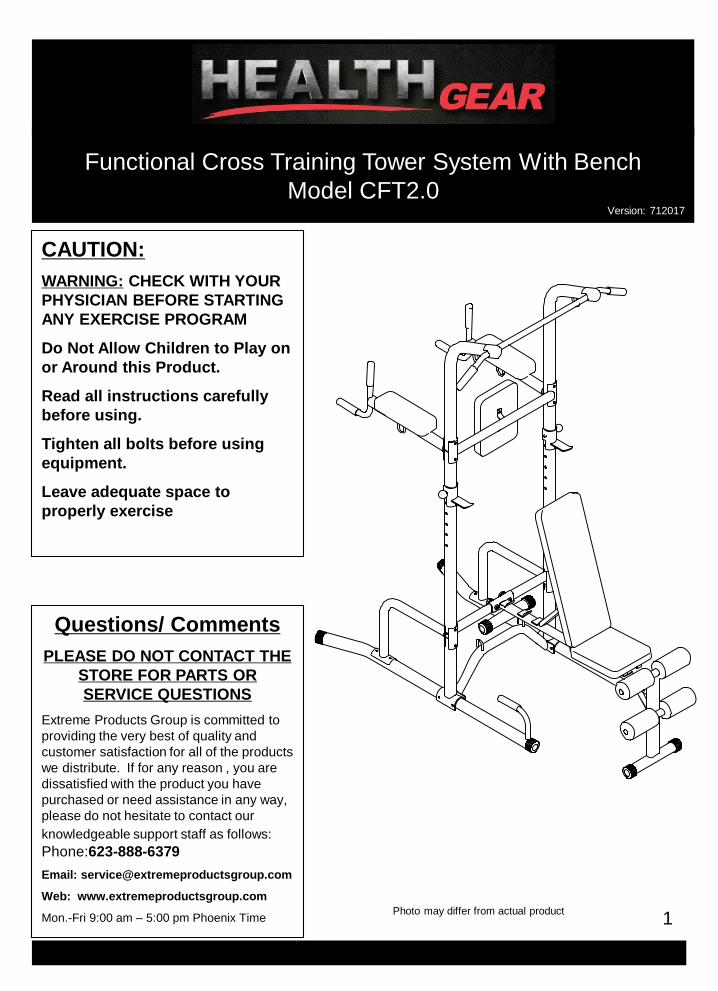
Functional Cross Training Tower System With Bench
Model CFT2.0
Photo may differ from actual product
CAUTION:
WARNING: CHECK WITH YOUR
PHYSICIAN BEFORE STARTING
ANY EXERCISE PROGRAM
Do Not Allow Children to Play on
or Around this Product.
Read all instructions carefully
before using.
Tighten all bolts before using
equipment.
Leave adequate space to
properly exercise
Questions/ Comments
PLEASE DO NOT CONTACT THE
STORE FOR PARTS OR
SERVICE QUESTIONS
Extreme Products Group is committed to
providing the very best of quality and
customer satisfaction for all of the products
we distribute. If for any reason , you are
dissatisfied with the product you have
purchased or need assistance in any way,
please do not hesitate to contact our
knowledgeable support staff as follows:
Phone:623-888-6379
Email: [email protected]
Web: www.extremeproductsgroup.com
Mon.-Fri 9:00 am – 5:00 pm Phoenix Time
S
Version: 712017
2
BEFORE BEGINNING ASSEMBLY…
Take a few moments to familiarize yourself with the specific parts and hardware included with your
product. Make sure all the parts and hardware are included in the carton and examine them for any
damage that may have occurred in transport. Some parts may be pre-assembled and pre-installed.
CAUTIONWARNING:
BEFORE STARTING ANY EXERCISE PROGRAM, CONSULT YOUR PHYSICIAN.
READ ALL WARNINGS AND PRECAUTIONS LISTED THROUGHOUT THIS MANUAL
Read all instructions very carefully before using equipment
Tighten all bolts securely before using equipment
Product Warranty Limited Liability
Extreme Products Group warrants that this product will be free from defects in materials and workmanship
for a period of 1 year on the frame, and 90 days on all other parts from date of purchase. This warranty
applies only to the original purchaser when purchase of the product is from an authorized retailer and is for
personal or household use, but not when the sale is for commercial use. This warranty is not transferable.
EXCEPT FOR THE LIMITED EXPRESS WARRANTY STATED HEREIN, EXTREME PRODUCTS
GROUP DISCLAIMS ALL OTHER EXPRESS OR IMPLIED WARRANTIES, INCLUDING BUT NOT
LIMITED TO IMPLIED WARRANTIES OF MERCHANTABILITY AND FITNESS FOR A PARTICULAR
PURPOSE. SOME STATES DO NOT ALLOW LIMITATIONS ON HOW LONG AN IMPLIED WARRANTY
LASTS, SO THE ABOVE LIMITATIONS MAY NOT APPLY TO YOU.
Extreme Products Group, will not be liable for any loss or damage, including incidental or consequential
damages of any kind, whether based upon warranty, contract or negligence and arising in connection with
the sale, use or repair of the product.
SOME STATES DO NOT ALLOW THE EXCLUSION OR LIMITATION OF INCIDENTAL OR
CONSEQUENTIAL DAMAGES, SO THE ABOVE LIMITATION OR EXCLUSION MAY NOT APPLY TO
YOU. THIS WARRANTY GIVES YOU SPECIFIC LEGAL RIGHTS AND YOU MAY HAVE OTHER
RIGHTS THAT VARY FROM STATE TO STATE.
In the event of failure of this product to conform to this warranty during the warranty period, please call
Extreme Products Group Customer Service Number at 623-888-6379 for assistance in the repair or
replacement of the product or any covered part. Extreme Products Group will repair or replace, at its own
option, the product or any covered part, except that this warranty does not cover damage caused by
accident ( including transit) , or repairs or attempted repairs by any person not authorized by Extreme
Products Group, or by vandalism, misuse, abuse, or alteration. The Warranty Period is based on the
purchase date of the product validated by the Authorized Retailers Register Receipt, or valid copy of
transaction statement. Shipping and Handling is not included. By continuing with the assembly and use of
this products acknowledges your understanding of the Warnings and Warranty Guidelines stated above.
If you require technical support under this warranty, please call Customer Service at ( 623-888-6379).
•For Any Parts Required, DO NOT CALL TECHNICAL SUPPORT. Please visit our web site at :
www.extremeproductsgroup.com
•TO VIEW AN ASSEMBLY VIDEO FOR THIS PRODUCT, PLEASE VISIT OUR WEB SITE

3
Parts Listing
• For Any Parts Required, DO NOT CALL TECHNICAL SUPPORT.
• Please visit our web site: www.extremeproductsgroup.com
ITEM DESCRIPTION Q'TY ITEM DESCRIPTION Q'TY
1 RIGHT BASE FRAME 1
2 LEFT BASE FRAME 1
24 SEAT FRAME 2
3VKR PAD SUPPORT 1
25 FOAM ROD 2
4VERTICAL STABILIZER 2
26 BACKREST ADJUSTABLE BAR
1
5 DIP HANDLE 2
27 SEAT INCLINE BAR 1
6 BASE CONNECT FRAME 1 29 SEAT CUSHION 1
7
BENCH SUPPORT
FRAME1
30FOAM ROLL
4
8LOWER UPRIGHT FRAME 2
31BENCH LOCKING KNOB
2
9 TOP UPRIGHT FRAME 2 32 50 ROUND END CAP 4
10 UPRIGHT FRAME 2 33 25 ROUND END PLUG 4
11 BAR CATCH 2 34 25 SQUARE END PLUG 8
12 CONNECTING PLATE 2 35 M10X45MM HEX BOLT 2
13 BACKREST CUSHION 1 36 M8X65MM HEX BOLT 4
14 VKR CUSHION 2 37 M10X75 CARRIAGE BOLT 8
15 CHIN-UP BAR 1 38 M10X75MM HEX BOLT 8
16 PVC HAND GRIP 8 39 M10X80MM HEX BOLT 4
17 BAR CATCH PIN 2 40 M8X16MM HEX BOLT 2
18 BASE FRAME CAP 4 41 M8X38MM HEX BOLT 8
19 BENCH MAIN FRAME 1 42 M10X180MM HEX BOLT 1
20 BENCH FRONT LEG 1 43 M10 WASHER 36
21BACKREST FRAME
2 44M8 WASHER
14
22 ROUND CAP WITH GAP 2 45M10 LOCK NUT
19
46223 LONG BACKREST CUSHION 1
28 1SUPPORT PLATE
M10X20 MM HEX BOLT

Parts Identifiler
4

5
Hardware Identifier

Hardware Identifier
6
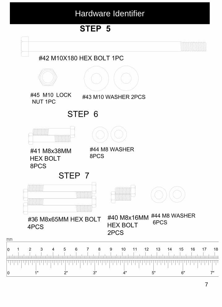
Hardware Identifier
7

8
Exploded View
* For Any Parts Required, DO NOT CALL TECHNICAL SUPPORT. Please visit our web site: www.extremeproductsgroup.com
TO VIEW AN ASSEMBLY VIDEO OF THIS PRODUCT, PLEASE VISIT OUR WEB
SITE AT: WWW.EXTREMEPRODUCTSGROUP.COM
* For Any Parts Required, DO NOT CALL TECHNICAL SUPPORT. Please visit our web site: www.extremeproductsgroup.com

9
Step 1- Lower Frame Assembly
* For Any Parts Required, DO NOT CALL TECHNICAL SUPPORT. Please visit our web site: www.extremeproductsgroup.com
Connect #1 Right Base Frame, #2 Left Base Frame and 2- #8 Lower Uprights
With #6 Base Connect frame using 4-#39 M10X80 Bolts and 8 #43 M10 washers
And 4- #45 M10 Locknuts as pictured in Diagram 1.
Diagram 1
Hand Tighten Bolts
39
43
39
3939
4543
45
43

10
Step 2- Support Braces & Middle Frame Assembly
* For Any Parts Required, DO NOT CALL TECHNICAL SUPPORT. Please visit our web site: www.extremeproductsgroup.com
A. Insert 2-#10 upright Frames over Tapered end of #8 Lower Uprigh
Frame and line up holes.
B. Using 2-#38 M10X75 Bolts and 2 # 43 M10 washers connect
#7 Bench support frame as pictured in Diagram 2
C. Attach 2- #4 Vertical Stabilizers to #10 Upright Frames using 4 # 38
M10X75 Bolts, 8 #43 M10 Washers, 4 #45 Locknuts and 2 #12 Connecting
Plates
D. Attach #4 Vertical Stabilizers to #1 and #2 Base Frames using 4 #37
M10 X 75 Bolts, 4-#43 M0 Washers and 4-#45 Locknuts as pictured in
Diagram 2
Diagram 2
Hand Tighten Bolts

11
Step 3- VKR & Upper Frame Assembly
* For Any Parts Required, DO NOT CALL TECHNICAL SUPPORT. Please visit our web site: www.extremeproductsgroup.com
A. Insert #9 Top Upright Frame over tapered end of #10 Upright Frame
And line up holes so curved portion of #9 Faces towards back of the
Tower.
B. Attach # 5 Dip Handle and # 3 VKR Pad Support to #9 Top Upright Frame
Using 4-#37 M10X75, 4-# 43 M10 Washers and 4-# 44 Locknuts
C. Attach #15 Chin-up Bar to the end of #9 Top Upright Frame using
2-#35 M10X45 Bolts and 2-# 43 M10 Washers and 2-#22 Round caps as
pictured in Diagram 3
Diagram 3
Tighten All Bolts
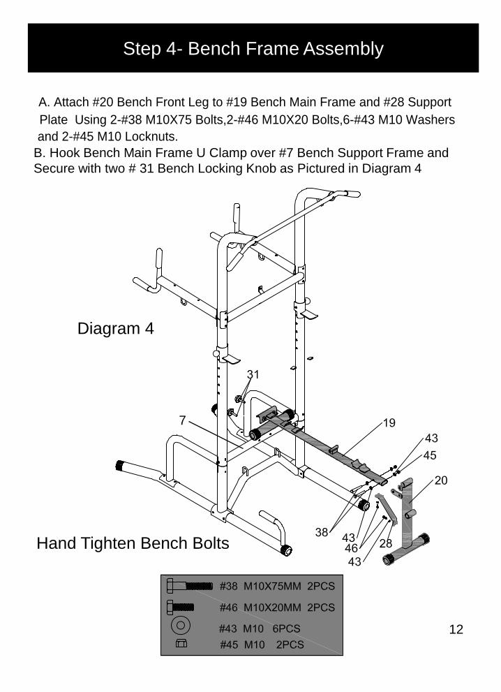
Step 4- Bench Frame Assembly
B. Hook Bench Main Frame U Clamp over #7 Bench Support Frame and
Secure with two # 31 Bench Locking Knob as Pictured in Diagram 4
Diagram 4
12
Hand Tighten Bench Bolts
A. Attach #20 Bench Front Leg to #19 Bench Main Frame and #28 Support Plate Using 2-#38 M10X75 Bolts,2-#46 M10X20 Bolts,6-#43 M10 Washers and 2-#45 M10 Locknuts.
7
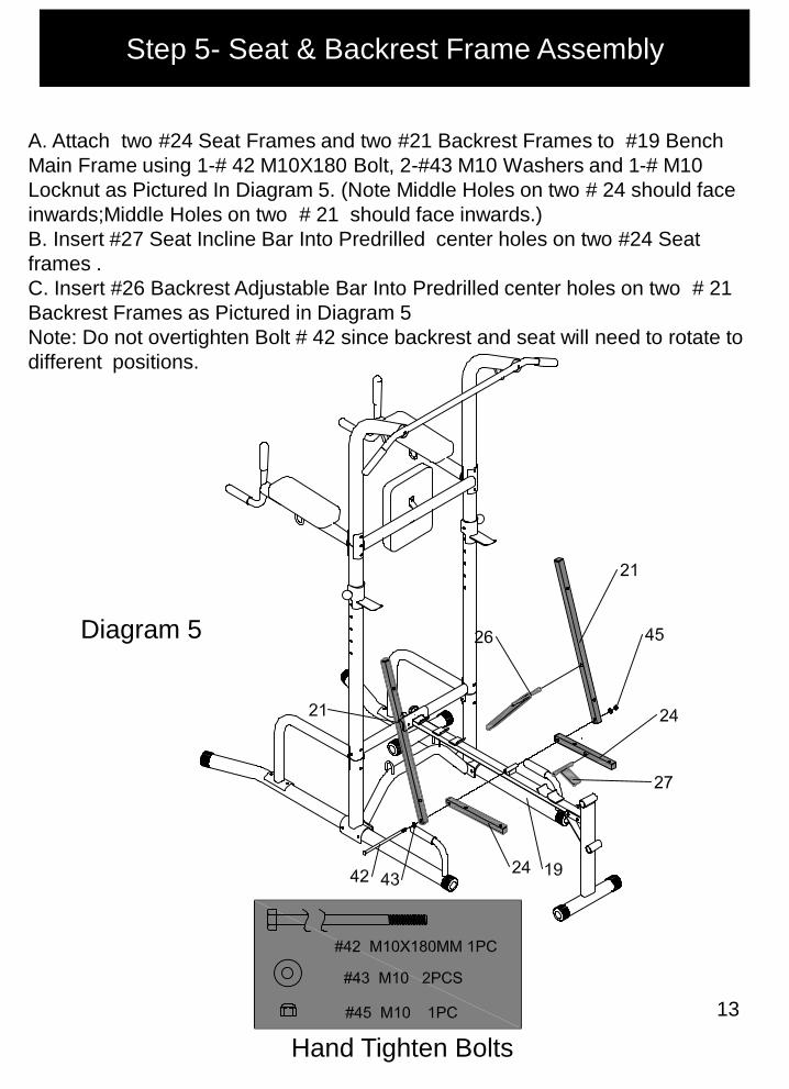
Step 5- Seat & Backrest Frame Assembly
13
A. Attach two #24 Seat Frames and two #21 Backrest Frames to #19 Bench
Main Frame using 1-# 42 M10X180 Bolt, 2-#43 M10 Washers and 1-# M10
Locknut as Pictured In Diagram 5. (Note Middle Holes on two # 24 should face
inwards;Middle Holes on two # 21 should face inwards.)
B. Insert #27 Seat Incline Bar Into Predrilled center holes on two #24 Seat
frames .
C. Insert #26 Backrest Adjustable Bar Into Predrilled center holes on two # 21
Backrest Frames as Pictured in Diagram 5
Note: Do not overtighten Bolt # 42 since backrest and seat will need to rotate to
different positions.
Diagram 5
Hand Tighten Bolts

Step 6- Bench Pads and Roller Assembly
14
A. Attach #29 Seat Cushion to two #24 Seat Frames Using 4-#41 M8X38
Bolts and 4-# 44 M8 Washers. (Note make sure #27 is Still mounted between
two #24)
B. Attach #23 Long Backrest Cushion to two #21 Backrest Frames using
4-#41 M8X38 Bolts and 4 M8 Washers . (Note make sure #26 is Still
mounted between two #21)
C. Slide and center #25 Foam Rods through Round Mounting Brackets on
#20 Bench Front Leg and slide 2 each # 30 Foam Rolls on each side for both
rods
Diagram 6
Tighten All Bench Bolts

15
STEP 7- Arm Pads & Back Pad
* For Any Parts Required, DO NOT CALL TECHNICAL SUPPORT. Please visit our web site: www.extremeproductsgroup.com
NOTE: TIGHTEN ALL BOLTS AT THIS TIME
A. Attach # 13 Backrest Cushion to #3 VKR Pad Support using 2#40 M8X16
Bolts and 2-# 44 M8 Washers
B. Attach #14 VKR Cushions to #5 Dip Handles using 4 M8X65 Bolts and 4-#
M8 Washers as pictured in Diagram 7
C. Attach #11 Bar Catch to #10 Upright Frame using #17 Bar Catch Pin at
Desired Height on both Sides
Diagram 7

16
WARNINGS & PRECAUTIONS
WARNING: 300 LB WEIGHT CAPACITY
To reduce the risk of serious injury, read all important precautions
instructions and warnings in this manual before using this Power Tower.
Extreme Products Group assumes no responsibility for personal injury or
property damage sustained by or through the use of this Tower.
YOU SHOULD NOT START ANY EXERCISE WITHOUT CONSULTING A
PHYSICIAN TO DETERMINE IF YOU HAVE ANY MEDICAL OR PHYSICAL
CONDITIONS THAT COULD PUT YOUR HEALTH AND SAFETY AT RISK, OR
PREVENT YOU FROM USING THE EQUIPMENT PROPERLY. YOUR
DOCTORS ADVICE IS ESSENTIAL IF YOU ARE TAKING MEDICATION THAT
AFFECTS YOUR HEART RATE, BLOOD PRESSURE OR CHOLESTEROL
LEVEL.
Be Aware of your body’s signals, Incorrect or excessive exercise can
damage your health. Stop exercising if you experience any of the
following symptoms. Pain, Tightness in your Chest, Irregular heartbeat,
Shortness of Breath, Lightheadedness, Dizziness or Feelings of Nausea. If
you do experience any of these symptoms, consult your doctor
immediately and discontinue use of this product.
KEEP CHILDREN AND PETS AWAY FROM THIS Power Tower. It is
designed for Adult Use Only
Use this product on a solid, flat level surface with a protective cover for
your floor or carpet.
Leave Adequate Space to Exercise.
Wear Suitable Clothing while exercising. Avoid Wearing Loose Clothing
that may bet caught in the equipment or that may restrict or prevent
movement.
INSURE THAT ALL NUTS, BOLTS, AND SCREWS ARE COMPLETELY
TIGHTENED BEFORE USING THIS PRODUCT.
ALWAYS WARM UP PROPERLY BEFORE EXERCISING AND COOL DOWN
AFTER EXERCISING.
* For Any Parts Required, DO NOT CALL TECHNICAL SUPPORT. Please visit our web site: www.extremeproductsgroup.com

17
Health Gear is a licensed Trademark and
Distributed By:
Extreme Products Group
6635 W. Happy Valley Rd
Suite A-104, #213
Phoenix, AZ 85310
Technical Support: 623-888-6379
Fax: 623-434-9100
Email: [email protected]
For All parts requests, please do not call our
Technical service number but visit our web
site at www.extremeproductsgroup.com
* For Any Parts Required, DO NOT CALL TECHNICAL SUPPORT. Please visit our web site: www.extremeproductsgroup.com