s aevaluation roof-wall details for the - · pdf fileof engineers roof-wall details for the...
TRANSCRIPT
TECHNICAL REPORT SL-87-29
S AEVALUATION OF ALTERNATEof Engineers ROOF-WALL DETAILS FOR THE
KEYWORKER BLAST SHELTER 'ro
by
0 Thomas R. Slawson, Stanley C. Woodson, Aaron L. Harris
Structures Laboratory
DEPARTMENT OF THE ARMYWaterways Experiment Station, Corps of Engineers
PO Box 631, Vicksburg, Mississippi 39180-0631
0
November 1987
Final ReportApproved For Public Release. Distrbuton Unlimited
DTC
repared JAN2 U -
E
repared for Federal Emergency Management AgencyLABOR Y Washington, DC 2047288 1 5 u

Destroy this report when no longer needed. Do not returnrit to the originator.
p
I
The findings in this report are not to be construed as an official
Department of the Army position unless so designatedby other authorized documents.
The contents of this report are not to be used for
advertising, publication, or promotional purposes.Citation of trade names does not constitute anofficial endorsement or approval of the use of
such commercial products.

TECHNICAL REPORT SL-87-29
EVALUATION OF ALTERNATEROOF-WALL DETAILS FOR THEKEYWORKER BLAST SHELTER
by
Thomas R. Slawson, Stanley C. Woodson, Aaron L. Harris
Structures Laboratory
DEPARTMENT OF THE ARMYWaterways Experiment Station, Corps of Engineers
PO Box 631, Vicksburg, Mississippi 39180-0631
November 1987Final Report
Approved For Public Release; Distribution Unlimited
This report has been reviewed in the Federal Emergency ManagementAgency and approved for publication. Approval doe not ignify that thecontents n* rily rflect the W s an policie e of the Fede1a EmergencyMaagement Agency.
Peuaedfor Federal Emergency Management AgencyWashington, DC 20472

EVALUATION OF ALTERNATE ROOF-WALL
DETAILS FOR THE KEYWORKER BLAST SHELTER
At the time this study was initiated, several civil defense policy
options were being analyzed for protection of the nation's industrial capabil-
ity and key workers. One option under consideration called for construction
of blast shelters to protect key workers remaining in high-risk areas during
a national crisis. In support of this option, the Federal Emergency Manage-
ment Agency (FEMA) tasked the US Army Engineer Division, Huntsville (HND), to
develop Keyworker shelter designs. The design required an earth-covered
shelter to resist the radiation and blast effects of a 1-MT nuclear detonation
at the 50-psi peak overpressure level. Personnel in the Structures Laboratory
of the US Army Engineer Waterways Experiment Station (WES) supported HND with
design calculations and design verification experiments.
In the construction of a large number of shelters, it is important that
the shelter design provide the required structural capacity at reasonable
costs. The original roof-wall reinforcement detail created a constructibility
problem that increased construction costs. The objective of the experimental
program described in this report was to evaluate alternate roof-wall joint
details for the Keyworker blast shelter in an effort to improve construct-
ibility without reducing structural capacity.
Three 1/4-scale reinforced concrete box-type models were statically
tested under uniform water pressure in the 6-foot-diameter Small Blast Load
Generator (SBLG) at WES. Two of the models (JDI and JD3) were reinforced
similarly to the original design except for the joint details. The third
model (JD2) was similar to the proposed final shelter design as evaluated in
the prototype tests conducted by WES. Based on test results, detail JD2 is
recommended for use in the final design.

TECHNICAL REPORT SL-87-Z T
EVALUATION OF ALTERNATEROOF-WALL DETAILS FOR THE
KEYWORKER BLAST SHELTERby
Thomas R. Slawson, Stanley C. Woodson, Aaron L. Harris
Structures Laboratory
DEPARTMENT OF THE ARMYWaterways Experiment Station, Corps of Engineers DYIC
PO Box 631, Vicksburg, Mississippi 39180-0631 (o y
Accssibl onWTIS GP.A&I-DTIC TABunazinounced Q
Tz-. )P" usti i Latio
November 1987 BitrbtinFinal Report --Avilabt-ltY 04108
Approved For Public Relbae; Distlbution Unlimited - Avall and/ '
Dist Specie3.
This report has been reviewed In the Federal Emergency ManagementAe .cy end approved for lIcation. Approval don not lffy that thecontents neosesily iet the vWs and po"le of the Fera Emergencyhim g w Agency.I
now tr Federal Emergency Management AgencyWashington, DC 20472

Unlasified2 ~ 61REPORT DOCUMENTAION PAGE
1. 11),R $R~tr ~~ ESTICTVE MARk(.GS
28 VCUM LA6ICATIORI AUTHORITY 3, DISTRIBUTION I AVAILAEILITY OF REPORTApproved for public release; distribution
2b. 0ECLASWIICATION1INGIRADNG S041OULE unlimited.
4. PINORIMIN ORGANMflON RE "NrJM004() S. MONITORING ORGANIZATION REPORT NUMMI(S1
Technical Report SL-87-29
IS. NAM OFPWORMINNG ORGAMAN l7b. OFIC SYMBOL. ?a. NAME OF MONITORING ORGA"NIZTONUSAEWES of A'""SW'Structures Laboratory I WESSS
6L. *0015 (OWv. Staft anud WC**j 7b. ADDRESS %71y, teat, nd WCd&)PO Box 631Vicksburg, MS 39180-0631
8116 NAME Of FUNDING ISPONSORING Wi OFFICE SYMBOL. 9. PROCUREMENT INSTRUMENT IDENTIFICATION NUMBEROGANIZATION Federal Of 41410cW)
EmrenM ana mentAgency ________
9L. ADDRESS (CJky, StaNt & and Cod" To. SOURCE 'of FUNOING NUMBESPROGRAM IPROJECT TAS 1wOR UNIT
Washington, DC 20472 ELEMENT NO. 1N 140ACC.ErSSION No.
11. TITLE O'Icuf SKaMNy Cooftaf",Evaluation of Alternate Roof-Wall Details for the Keyworker Blast Shelter
12. PERSONAL AUTHOR(S)Slwo.Thomas R.. Woodson, Stanley C., and Harris, Aaron L.
13a. TYPE OF REPORT 113b. TIME COVERED 14. DATE OF REPORT (Yeav, Med, a) . PAGE COuNTFia pnort F ROM _____TO I November 1987 I 106
16 SUPPLEMENTARY NOTATIONIAvailable from National Technical Information Service, 5285 Port Royal Road,
~Sringfield. VA 22161.iT ~COSATI COCEs 18. SUBJECT TERMS (Cornffri on owi M f IWC.Uar, &Wd 'danaf 6y #lack qnbr
FIELD GROUP SUu-ROUP Knee joints Reinforcement e tailsLoad-deformation behavior Static testingReinforced concrete slabs Uniform loading
5 ~~9. AISTRACT CConIdue on rv&=~e N newmrp Atd WN"( by ~oc numb")jAt the time this study was initiated, several civil defense policy options were being
analyzed for protection ot the nation's indusLxidl LUPdlility and key wo~rkers. Onea Optionunder consideration called for construction of blast shelters to protect key workersremaining in high-risk areas during a national crisis. In support of this option, theFederal Emergency Management Agency (FEMA) tasked the US Army Engineer Division,Huntsville (HND), to develop Keyworker shelter designs. The design required an earth-covered shelter to resist the radiation and blast effects of a 1-MT nuclear detonation atthe 50-psi peak overpressure level. Personnel in the Structures Laboratory of the US ArmyEngineer Waterways Experiment Station (WES) supported HND with design calculations anddesign verification experiments.
In the construction of a large number of shelters, it is important that the shelterdesign provide the required structural capacity at reasonable costs. The original roof-wall reinforcement detail created a constructibility problem that increased construction
20. DISTRIGUTIO#IAVAIIAIRM~ OF ABSTRACT -. AI"RC SURITY ClASIFICTIO
QUNCLSFIOAMD 0 SAmE AS AT. gon MI Unclass fied~22a. "rOFIIINitI2b. VILAO 0*AE oe Z OFFICE SYMBOL
DO POno 1473.8 W" MM B APRI 0m~ "abe WftE WIOW BOWN&~i Say .EIATION OF THIS PAGEAN~ 10 eebulsgs.
Unclassified
L

UnclassifiedgaoUmgyy e LagIicATOe OF T019 PAON
19. ABSTRACT (Continued).
,° costs. The objective of the experimental program described in this report was toevaluate alternate roof-wall joint details for the Keyworker blast shelter in an effortto improve constructibility without reducing structural capacity. W
Three 1/4-scale reinforced concrete box-type models were statically tested underuniform water pressure in the 6-foot-diameter Small Blast Load Generator (SBLG) at WES.Two of the models (JDI and JD3) were reinforced similarly to the original design exceptfor the joint details. The third model (JD2) was similar to the proposed final shelterdesign as evaluated in the prototype tests conducted by WES. Based on the testresults, detail JD2 is recommended for use in the final design.
UnclassifiedSSGU*? Cfh~iUPAIWOP YWoO PSOS
f I

PREFACE
The research reported herein was sponsored by the Federal Emergency
Management Agency (FEMA) through the US Army Engineer Division, Huntsville
(HND).
Construction and testing were conducted by personnel of the Structures
Laboratory (SL), US Army Engineer Waterways Experiment Station (WES), under
the general supervision of Messrs. Bryant Mather, Chief, SL, and James T.
Ballard, Assistant Chief, SL. Chief of the Structural Mechanics Division
(SMD), SL, during this investigation was Dr. Jimmy P. Balsara. The project
was managed by Dr. Sam A. Kiger, SMD. Messrs. Thomas R. Slawson, Stanley C.
Woodson, and Aaron L. Harris, SMD, supervised the experiments and prepared
this report.
COL Dwayne G. Lee, CE, is the Commander and Director of WES. Dr. Robert
W. Whalin is Technical Director.
I1

CONTENTS
Page
PREFACE ............................................................... 1
LIST OF ILLUSTRATIONS ................................................. 3
LIST OF TABLES ........................................................ 3
CONVERSION FACTORS, NON-SI TO SI (METRIC) UNITS OF MEASUREMENT ........ 4
CHAPTER 1 INTRODUCTION ............................................... 5
1.1 BACKGROUND ..................................................... 51.2 OBJECTIVE ...................................................... 61.3 SCOPE ........................................................ 6
CHAPTER 2 TEST DESCRIPTION ........................................... 8
2.1 CONSTRUCTION DETAILS ........................................... 82.2 STRUCTURAL MATERIAL PROPERTIES ................................. 9
2.2.1 Concrete .................................................. 92.2.2 Reinforcing Steel ......................................... 9
2.3 LOADING DEVICE ................................................. 102.4 INSTRUMENTATION .............................................. 102.5 TEST PROCEDURE ............................................... 11
CHAPTER 3 TEST RESULTS ............................................... 27
3.1 GENERAL ........................................................ 273.2 LOAD-DEFLECTION BEHAVIOR ....................................... 273.3 STRUCTURAL DAMAGE .............................................. 28
CHAPTER 4 ANALYSIS ................................................... 38
4.1 STRAIN GAGE DATA ............................................... 384.2 JOINT BEHAVIOR AND RELATED EFFECTS ............................. 394.3 COMPARISON OF JOINT DETAIL MODELS WITH STRUCTURAL ELEMENT S3 ... 40
CHAPTER 5 CONCLUSIONS AND RECOMMENDATIONS ............................ 43
5.1 CONCLUSIONS .................................................... 435.2 RECOM MENDATIONS ................................................ 44
REFERENCES ............................................................ 45
APPENDIX A: RECOVERED DATA ........................................... 47
2

LIST OF ILLUSTRATIONS
1 Reinforcement details for JD .................................. 142 Reinforcement details for JD3 .................................. 153 Reinforcement fabrication details for JD and JD3 .............. 164 Reinforcement details for JD2 .................................. 175 Reinforcement placement details for JD2 ........................ 186 Reinforcement fabrication details for JD2 ...................... 197 Truss bar fabrication details for JD2 .......................... 208 Construction of model JD ...................................... 219 Close-up view of JD joint detail .............................. 21
10 Construction of model JD2 ...................................... 2211 Close-up view of JD2 joint detail .............................. 2212 Construction of model JD3 ...................................... 2313 Close-up of JD3 joint detail ................................... 2314 Test configuration ............................................. 2415 Strain gage locations for JD and JD3 .......................... 2516 Strain gage locations for JD2 and typical deflection
gage locations ................................................. 2617 Load-deflection relationship for a one-way slab with
restrained ends ................................................ 3118 Posttest view of the roof surface of JD ....................... 3219 Posttest view of the bottom of the roof slab of JD ............ 3220 Posttest end view of JDI ....................................... 3321 Posttest side view of JD ...................................... 3322 Posttest view of the roof surface of JD2 ....................... 3423 Posttest view of the bottom of the roof slab of JD2 ............ 3424 Posttest end view of JD2 ....................................... 3525 Posttest side view of JD2 ...................................... 35f Pnft-tp.it view of the roof qiirfnnP of .M13 .......................... 36
27 Posttest view of the bottom of the roof slab of JD3 ............ 3628 Posttest end view of JD3 ....................................... 3729 Posttest side view of JD3 ...................................... 3730 Comparison of static load-deflection behavior .................. 42
LIST OF TABLES
Table Page
1 Summary of roof reinforcement ratios including dowelreinforcement at critical sections ............................. 12
2 Results of tensile tests performed on reinforcing steel ........ 133 Data summary for joint detail tests ............................ 30
3

CONVERSION FACTORS, NON-SI TO SI (METRIC)UNITS OF MEASUREMENT
Non-SI units of measurement used in this report can be converted to SI
(metric) units as follows:
Multiply By To Obtain
cubic feet 0.02831685 cubic metres
degrees (angle) 0.01745329 radians
feet 0.3048 metres
g's (standard free fall) 9.80665 metres persecond squared
inches 25.4 millimetres
kilotons (nuclear equivalent 4.184 terajoulesof TNT.
megatons (nuclear equivalent 4.184 petajoulesof TNT)
pounds (force) per square inch 0.006894757 megapascals
pounds (mass) 0.4535924 kilograms
pound (mass) per cubic foot 16.01846 kilograms percubic metre
tons (2,000 pounds, mass) 907.1847 kilograms
4

EVALUATION OF ALTERNATE ROOF-WALL DETAILS
FOR THE KEYWORKER BLAST SHELTER
CHAPTER 1
INTRODUCTION
1.1 BACKGROUND
At the time this study was initiated, several civil defense policy
options were being analyzed for protection of the nation's industrial
capability and key workers. One option under consideration called for
construction of blast shelters to protect key workers remaining in high-risk
areas during a national crisis. In support of this option the Federal
Emergency Management Agency (FEMA) tasked the U.S. Army Engineer Division,
Huntsville (HND) to develop keyworker shelter designs. The design required an
earth covered shelter to resist the radiation and blast effects of a I-MT*
nuclear detonation at the 50-psi peak overpressure level. Personnel in the
Structures Laboratory of the U.S. Army Engineer Waterways Experiment Station
(WES) supported the HND with design calculations and design verification
experiments.
A preliminary structural design for the shelter was developed based on
computational procedures developed by Kiger, Slawson and Hyde (1984) in the
Shallow-Buried Structures Research Program at WES. Using a roof slab
thickness of 10 inches, a span of 11.3 feet, and limiting the mid-span
deflection to 7 inches, the minimum required tension and compression
reinforcement ratios were determined to be approximately 0.007. The roof slab
principal reinforcement extended into and 40 bar diameters down the walls.
This reinforcement embedment resulted in the requirement that the roof slab
reinforcement be placed into position prior to placement of concrete in the
walls. This design was experimentally evaluated using scale-model testing.
Six static tests and twelve dynamic tests were performed on approximately
1/4-scale models of the Keyworker blast shelter as reported by Slawson,
et. al. (1985). The effects of backfill type, concrete strength, and depth-
of-burial on structural response were investigated. The roof slab was
* A table of factors for converting non-SI units of measurement to SI (metric)
units is presented on page 4.
5

determined to be capable of resisting a 1-Mt weapon at approximately a 150-psi
peak overpressure level with moderate damage. Permanent mid-span deflections
varied from less than 0.1 inch to collapse in the test series. The failure
mode for these models was the classical three-hinge mechanism with roof yield
lines at mid-span and at the interior face of the walls. The roof-wall
connection performed adequately during this test series. The joint details
provided adequate embedment length to prevent principal roof reinforcement
pullout and allowed large plastic rotations without premature failure. The
joint details used in these test elements will be referred to throughout this
report as the "original" joint details for the Keyworker blast shelter.
In the construction of a large number of shelters, it was important that
the shelter design provide the required structural capacity at reasonable
costs. The original roof-wall reinforcement detail created a constructibility
problem that increased construction costs. The research reported herein
investigates the modification of the roof-wall connection detail to allow
casting of the structure walls without requiring the roof reinforcement to be
in place. This facilitates removal of the wall forms from the inside of the
shelter through the open roof and allows the placement of a construction joint
near the top of the walls. This should decrease construction costs and the
amount of time required for casting of the prototype structure.
1.2 OBJECTIVE
The objective of this test program was to evaluate alternate roof-wall
joint details for the Keyworker blast shelter in an effort to improve
onstructibility without reducing structural capacity.
1.3 SCOPE
Three 1/4-acale reinforced-concrete box-type models were statically
tested under uniform water pressure in the 6-foot-diameter Small Blast Load
Generator (SBLG) at WES. Two of the models (JD1 and JD3) were reinforced
similar to the original design except for the joint details. The third model
(JD2) was identical to the models studied in the Yield Effects Tests (Slawson,
Garner and Woodson, 1986). The principal reinforcement details in JD2 were
6

!
developed from tests investigating stirrup details (Woodson, 1985) and
principal reinforcement details (Woodson and Garner, 1985). JD2 was
constructed after the testing of JD1 and JD3; therefore, the results of the
two tests aided in the design of the joint details in JD2. JD2 represented
the recommended WES design and was statically tested to: (a) allow a
comparison of the model's static response with the original structure's static
behavior and (b) validate the structural design (including joint details)
recommended for the Keyworker blast shelter.
7

CHAPTER 2
TEST DESCRIPTION
2.1 CONSTRUCTION DETAILS
The three test specimens were one-way, open-ended reinforced-concrete box
elements. All models had a roof clear span of 33 inches, a clear height of
30 inches, and wall and floor thicknesses of 2.25 inches. Specimens JD1 and
JD3 had roof thicknesses of 2.5 inches and roof effective depths of
approximately 1.8 inches at mid-span. JD2 had a roof thickness of 2.25 inches
and a roof effective depth of approximately 1.6 inches at mid-span.
The tension and compression steel ratios in the roofs, floors, and walls
of JD1 and JD3 were approximately equal to 0.007 (neglecting additional dowel
reinforcement at critical sections). Models JD1 and JD3 also contained
stirrups in the roofs, floors, and walls. Based on previous test data
(Woodson and Garner 1985), approximately 75 percent of the roof and floor
principal reinforcement was placed in the tension zones, and 25 percent was
placed in the compression zones in JD2. This required the use of
reinforcement bent, such that it was placed in the exterior face of the roof
or floor slab near the supports and in the interior face at mid-span. This
was accomplished by the use of truss bars as shown in Figure 7. Tension and
compression steel ratios in the roof and floor of JD2 at mid-span were
approximately 0.012 and 0.004, respectively. Stirrups were placed only in the
walls of JD2. Steel reinforcement ratios and effective depths for all of the
elements are summarized in Table 1.
Construction details for test specimens JD1 and JD3 are presented in
Figures 1 through 3. Joint details for both models allow complete
construction of the walls prior to placement of roof reinforcement in a
prototype structure. The only difference in the two models was that a
180-degree hook was used at the ends of the roof principal steel in JD1, and a
90-degree hook was used in JD3. The 90-degree hook extended only 0.75 inch (3
inches in prototype) into the wall below the bottoi6 face of the roof slab.
Additional reinforcement (mid-span dowels) was placed in the tension zone
(bottom face) at the roof's mid-span in JD1 and JD3. The purpose of the mid-
8

span dowels was to increase the moment capacity of the roof slab at mid-span,
thereby prohibiting premature failure at the roof mid-span and allowing a
study of the joint detail behavior.
Construction details for test specimen JD2 are presented in Figures 4
through 7. Midspan dowels were not required in JD2 because the tension
reinforcement ratio at mid-span was large enough to insure a ductile
response. A 180-degree hook was used at the ends of the roof principal
steel. Alternating wall principal reinforcement bars were bent 90 degrees and
extended along the top face of the roof a length of about 30 percent of the
roof's clear span. The joint also contained dowels between principal steel
locations that reinforced the exterior face of the wall and extended into the
interior face of the roof. The dowels helped in maintaining a balanced joint
detail design by increasing the moment capacity of the wall near the joint to
prevent wall failure prior to roof failure.
Photographs taken during construction of the models are shown in Figures
8 through 13.
2.2 STRUCTURAL MATERIAL PROPERTIES
2.2.1 Concrete
The concrete mix was designed to have a 28-day compressive strength of
3,000 psi. The mix consisted of Type I Portland cement obtained from a local
commercial supplier, a natural siliceous sand fine aggregate, and a crushed
limestone coarse aggregate with a 3/8-inch maximum diameter. Compressive
tests on concrete cylinders yielded mean values of 28-day strength for JD1,
JD2, and JD3 of 2,520, 2,790, and 2,940 psi, respectively. The mean values
for the test day compressive strength of the concrete in models JD1, JD2, and
JD3 were 2,680, 3,150, and 2,940 psi, respectively.
2.2.2 Reinforcing Steel
The principal reinforcing steel used in models JD1 and JD3 was ASTM
(1984) Grade 60 No. 2 rebar. The principal reinforcing in model JD2 consisted
of 0.195-inch diameter (D3) deformed wire that had been heat treated to model
9

Grade 60 rebar. Stirrups and temperature steel in all models consisted of
heat-treated 0.11-inch-diameter (D) deformed wire. Results of tensile tests
on the reinforcement are presented in Table 2.
2.3 LOADING DEVICE
The static tests were performed in the SBLG at WES. The device consists
of a Central Firing Station (CFS) (a massive posttensioned concrete reaction
structure) and a test chamber. The test chamber consists of two 5-foot
11-3/4-inch inside diameter steel rings stacked on a movable platen to form a
cylindrical chamber 6-feet deep. The loading device can be used for both
static and dynamic tests. Slowly applied (static) loading can be achieved by
sealing the exhaust ports and pumping water into the chamber. A detailed
description of the use of the static test device is given by Huff (1969). The
three tests discussed in this report were tested statically in the
configuration shown in Figure 14.
2.4 INSTRUMENTATION
Each model was instrumented for rebar strain and roof displacement. In
addition, water loading pressure and soil-stress measurements were made. The
data were recorded on a Sangamo Sabre III FM magnetic tape recorder. The data
were digitized and plotted with water pressure as the ordinate. Figures 15
and 16 show the instrumentation layout for the test specimens.
Soil-stress measurements were made in the free field at a depth of
1/2-inch below the roof's surface at a distance of 12 inches from the model's
wall. Two Kulite SE Model VQV-O80-LR soil-stress gages (SEI and SE2) having
ranges of 200 psi were used in each test.
Reinforcement steel strains were measured on the inside (EI) and outside
(EO) of principal steel using Micro-Measurements single-axis, metal film,
350-ohm, temperature-compensated, 1/8-inch strain gages. The gages were model
number EA-06-125BZ-350. In addition, dowel strains (E) were measured in
tests JD1 and JD3, and truss bars strains (E) were measured in test JD2.
10

Two Celesco PT-101 displacement transducers were used in each test, one
at mid-span (D1) and one at quarter-span (D2). The transducers had a maximum
allowable working range of 10 inches.
Two Kulite Model HKMS-375, 500-psi pressure gages (P1 and P2) were
mounted in the test chamber to measure the water pressure applied to the
roof's surface.
2.5 TEST PROCEDURE
The 6-foot-diameter SBLG (Figure 14) was used to statically test each
model. Prior to placement of the model in the SBLG, sand was placed and
compacted to a level of 3 feet 6-1/4 inches below the top of the chamber. The
box element was placed on the compacted sand, and instrumentation gages were
connected to cables passing through steel endplates and the test chamber's
wall to a junction terminal box. The steel plates covered the open ends of
the model, and thrust rods were installed between the two plates to keep the
plates from bearing against the structure. Silicon caulk filled the gaps
between the steel plates and the model.
Sand backfill was compacted in 6-inch lifts to the roof surface level
(approximately 8 inches below the top of the test chamber). A 1/4-inch-thick
neoprene membrane was placed over the model and clamped to a ring along the
inside face of the chamber to waterproof the structure and backfill during the
test. The lid was placed on the chamber and the assembly was moved on tracks
into the CFS. Water was pumped into the chamber above the structure, pushing
the chamber's lid against the CFS and applying a slowly increasing uniform
load to the roof's surface. The displacement gage located at mid-span and one
of the pressure gages were monitored on an X-Y plotter during the test. The
test was terminated when the incipient collapse deflection of the roof slab
was reached or when the water pressure suddenly decreased due to rupture of
the neoprene membrane.
11

b
Table 1. Summary of roof reinforcement ratios including dowelreinforcement at critical sections.
Effective Depth, d(inches) Reinforcement Ratio
Mid-Span Support
Model Mid-Span Support Top Bottom Top Bottom
JD1 1.8 2.0 0.0074 0.01140 0.0126 0.0067
JD2 1.6 1.6 0.0040 0.0120 0.0160 0.0080
JD3 1.8 2.0 0.0074 0.0140 0.0126 0.0067
Note:
The reinforcement ratios were calculated for each face of the roof slabsection at the mid-span and at the face of the support by the following:A/bd, where:
A - the total area of steel in the layerb - the length of the structural model (33 inches)d - the distance from the compression face of the slab to the centroid of the
tensile reinforcement
12

Table 2. Results of tensile tests performed on reinforcing steel.
Yield Stress Ultimate StressSpecimen ksi ksi
D1 Deformed Wire 60.4 62.9(0.11-inch dia) 67.7 71.2
59.8 63.760.8 63.455.7 58.9
(mean) (60.9) (64.0)
D3 Deformed Wire 59.9 66.5(0.195-inch diam.) 66.8 75.0
68.2 74.4
74.0 79.270.4 77.0
(mean) (67.9) (74.4)
No. 2 Rebar 73.7 78.7(0.25-inch diam.) 58.3 63.0
73.8 78.872.1 77.268.4 73.6
(mean) (69.3) (74.3)
13

(32-34" LONG D3 DEFORMED WIRE BEARING BAR
A4,NO. 2 RE-BAR (16- LONGNO. 2R RAR DOWEL MIOSPAN DOWEL)
INSIDE RADIUS -112"RF
A -4
NOTE: STIRRUPS NOT SHOWN
FLOOR (REINFORCEDI
_______AA____ 37- 1/2"mo
D I DEFORMED WIRE SPACED
0D1 DEFORMED WIRE @."..r38 OE
STIRRUPS SPACED a 19 1- 1/22 D. C1516
NO. 2 RE-BAR MIOPAN NO. 2 RE-BAR PRINCIPAL L9/l6" COVERDOWELS SPACED 0 "134O" STEEL SPACED 0 3-3/4" 0. C
SECTION A-A
Dl DEFORMED 03 DEFORMEDWIRE STIRRUPS 11WIRE SPACED& 130" OC. r-l /2" COVERSPACED 0 F- 1/2". C.
NO. 2 RE-BAR DOWELS___SPACED 03-3/4"0D.C. NO. 2 RE-BAR PRINCIPALI L,, 32..CO VER
STEEL SPACED 314r,
SECTION B-B
Figure 1. Reinforcemuent details for JD1.
14

32-314" LONG D3 DEFORMED WIRE BEARING BAR
A ~1 NO. 2 RE-BAR (16" LONG)NO. 2 RE-BAR DOWEL S MIDSPAN DOWEL
1/2" INSIDE RADIUS
BA
FLOOR (REINFORCEDSIMILAR TO ROOF)
* 37-1)2"
D I DEFORMED WIRE
D I DEFORMED WIRE PC 01"C. 3 COE
STIRRUPS SPACED 0
NO. 2 RE-BARPRINCIPAL STEEL 9/16"COVERSPACED 0 -3-3/4 " 0.C. NO. 2 RE-BAR MIDWPAN DOWELS SPACED@~ 3-3/4', .
SECTION A-A
D I DEFORMED WIRE SPACFOED WIR0EO 1 1/32"COVERSTIRRUPS SPACED/-PCD00..
NO. 2 RE-BAR DOWELS 11?42"COVERSPACED 0 3-314 " 0.C.
NO. 2 RE-BA R PRINCIPAL STEELSPA'CED *3-3/4"0. C.
SECTION B-0
Figure 2. Reintorooment details for JD3.
mh -
15

NO.2 REBAR
DI DEFORMED WIRE(DIA = 0. 1 f')
a. ROOF AND WALL SHEAR STIRRUP DETAIL
8-7/16"
:3111 1.S1D ER D11USNO. 2 REBAR
b. ROOF-WALL CONNECTION DOWEL
Figure 3. Reinforoement tabrication details for JD1 and JD3.
16

03 DEFORMED WIRE ABEARING BARI I
-ROOF
A *JBB
F LO[
FLOR(REINFORCEDSIMILAR TO ROOF)
D I DEFORMED WIRE OVERSPA CEO *3.0O.C .-r l ,',VE
2 BENT D3 DEFORMEDW - 33" STRAIGHT D3 DEFORMED WIRE
SPACED0 4-7/8" 0.C.
SECTION A-A
D I DEFORMED WIREDI DEFORMED /SPACED e30.r. i-12"COVER
WIRE STIRRUPS S E .__JC1
SPACED V I - Ph A A A1-1/2" o.-C. - _________________________ -.1=.
D3 DEFORMED WIRE ,17/,,PRINCIPAL STEEL =1"CO VER
SPACED 0SPACED"0.C.-7/336"O.C.SPACED @2-./?6"3.C.D3 DEFORMED WIRE
i' ' - -- ;DOWEL SPACED 0 2-7116-"O.C
SECTION B-B
Figure 4. Reinforcement detailb for JD2.
17
..... .. .. ..... . .. . . . .... ... ...... . ... ... .. .. ... . . . . . ... . ... . ... ... ... ... . . ... .. .

D3 BEARING BAR,-DOWEL 1-9,/32"
112"-4 9"71V"T
1/2"-12
a. STRAIGHT PRINCIPAL STEEL LOCATION
F igu 5. Reinfocemen paentdailsfr
I I' y 1/2" ~61/2" "ri I
= ,--- ...---...
D3 BEARING BAR m 'P I
~NOTE: BARS NOT DRAWN AT EXACT DEPTHS
~ 1/2'FOR CLARITY
b. BENT PRINCIPAL STEEL LOCATION
Figure 5. Reinforcement placement details for JD2.
18
Yt EFREDWRD3 DEFORMED WIRE
(DIA-O. 195")
a. WALL SHEAR STIRRUP
25/302" 10-27/32"
INSIDE D3 WIRE
RADIUS- 19132"
In
b. ROOF - WALL CONNECTION DOWEL DETAIL
Figure 6. Reinforcement fabrication details for JD2.
19

6-6-/12
INSIDEWIERERADIUS- 13132" N D3 DEFORE
INSIDE RADIUS -191327
1-/2 19-11 137132
6-27132"J
JD2 BENT BAR DETAIL
Figure 7. Truss bar fabrication details for JD2.
20

Figure 8. Construction of model JD1.
I
Figure 9. Close-up view of JD1 joint detail.
21

Figure 10. Construction of model JD2.
Figure 11. Close-up view of JD2 joint detail.
22

17A R8
p 1
Figure 12. Construction of model JD3.
Figure 13. Close-up of JD3 joint detail.
23

-SBLG STEEL RINGSw-O OF BACKFILL
TEST*ELEMENT--V
......
S CAINATD
TEST CONFIGURATION
Figure 114. Test configuration.
24

El E 12 Ei
67-11-
a. JD1 STRAIN - GAGE LOCATIONS
______________________EO - STRAIN GAGE ON OUTER PRINCIPAL STEELEl - STRAIN GAGE ON INNER PRINCIPAL STEEL
J-/1 -314" 4" ED - STRAIN GAGE ON DOWEL
r~i 912 EDI 502
b. .03 STRAIN -GAGE LOCATIONS
Figure 15. Strain gage locations for MD and JD3.
25

LEGENDEOI E02 E03
E -U~ ESTRAIN GAGE ON
3-3/4" -- BENT PRINCIPAL STEEL
. oE2I I E13 E3 ROOF EO - STRAIN GAGE ONOUTER PRINCIPAL STEEL
El - STRAIN GAGE ONINNER PRINCIPAL STEEL
F37-112-
JD2 STRAIN GAGE LOCATIONS
DI
TYPICAL ROOF DEFLECTION GAGE LOCATIONS
Figure 16. Strain gage locations for JD2 andtypical deflection gage locations.
26

r
CHAPTER 3
TEST RESULTS
3.1 GENERAL
Test results are presented in this chapter and recovered data are
presented in Appendix A. A general description of the data produced and of
the structural performance of each model is presented herein. Further
discussion and analyses are presented in Chapter 4. A recovered data summary
for the three tests are presented in Table 3.
3.2 LOAD-DEFLECTION BEHAVIOR
The flexural strength of a restrained slab is enhanced by compressive
membrane forces, causing the ultimate capacity to be greater than that
calculated using classical yield-line theory. Compressive membrane behavior
of slabs is documented by Park and Gamble (1980) and Guice (1986a, 1986b).
Figure 17 shows the load-deflection relationship for laterally restrained one-
way slabs. As the load is increased from A to B, with the help of compressive
membrane forces, the slab reaches its enhanced ultimate load at point B. With
an increase in deformation past point B, the compressive membrane enhancement
is reduced by a P-A effect until point C is reached. Normally point C
corresponds to the yield-line capacity at a deflection that varies from the
effective depth to the slab thickness for fixed-fixed slabs similar to these
test models. Beyond point C, the tensile reinforcement acts as a catenary to
carry the load with full depth cracking of the concrete at the mid-span region
of the slab.
Ultimate resistances for JD1, JD2, and JD3 were 55, 38, and 63 psi,
respectively. Deflection at ultimate resistance ranged from 0.55 to 0.75 inch
with an average of 0.67 inch. The average ratio of deflection at ultimate
resistance-to-slab thickness for the tests was 0.27.
Enhanced tensile membrane behavior was observed in Test JD2. The maximum
pressure in the tensile membrane region was 34 psi. The test was stopped at
incipient collapse so that the roof failure mechanism could be observed. End-
of-test pressures for Test JD1 and Test JD3 were 36 and 39 psi, respectively.
27

No tensile membrane enhancement in slab resistance was noted for tests JD1 and
JD3. Test JD1 was stopped because of large deflections to the roof slab. The
neoprene membrane was ruptured in Test JD3, thus, the sudden decrease in
pressure.
Experimental pressure versus deflection at ultimate resistance and at
maximum resistance in the tensile membrane region for the tests are given in
Table 4.
3.3 STRUCTURAL DAMAGE
The structural models were uncovered and examined immediately after
testing. In all three cases, the roofs cracked at the supports and at mid-
span on the top surface and at mid-span on the bottom surface. A careful
examination of the models after each test provided significant information
about overall response. Crack patterns and failures of steel reinforcement
were the most significant characteristics that were observed. All visible
cracks in the slabs were highlighted with markers. Records were kept of the
widths and depths of the crack bands at mid-span in the tension and
compression zones, at the supports in the tension zones, and in the wall
supports in the tension zones.
Maximum permanent roof mid-span deflection for Test JD1 was 5-1/8 inches,
exposing reinforcing at mid-span and at the supports. Cracks at mid-span and
at the roof supports ranged in depth from 1/4-inch to the thickness of the
roof. Although the band of cracking at mid-span was primarily narrow on the
top of the roof slab, the bottom surface revealed additional hairline cracks
across the roof span. Wall cracks occurred near the top of both supports and
exposed a large percentage of principal reinforcement from the roof-wall
connection. See Figures 18 through 21 for posttest photographs of Test JD1.
Test JD2 resulted in a permanent mid-span roof deflection of
5-1/2 inches. Significant cracking occurred at mid-span and at the
supports. The crack at mid-span was the depth of the roof across the entire
structure. All roof reinforcing at mid-span was exposed and all bottom mid-
span bars were broken, except one. Although the mid-span crack was much more
extensive than that of Test 1, there were fewer hairline cracks across the top
and bottom surfaces of the roof. The width of the crack zone at mid-span
28

ranged from 2-1/2 to 11-1/2 inches on the top surface of the roof. Cracks
ranging from 1/2- to 1-1/2-inches deep occurred at the supports. Posttest
photographs of Test JD2 are shown in Figures 22 through 25.
The response of the model in Test JD3 was very similar to the model in
Test JDI. Permanent roof deflection was 5-1/4 inches. The supports were
severely damaged as much cracking and exposure of reinforcement was
observed. The mid-span crack zone was much more widespread across the top and
bottom surfaces of the roof. Cracks occurred heavily at the top of the walls
as well (See Figures 26 through 29). The roof-wall joints in tests JDI and
JD3 failed by diagonal splitting. The joints of test JD2 did not fail during
the test.
29
Table 3. Data Summary for Joint Detail Tests.
Gage Location Test JDI Test JD2 Test JD3
Soil Stress SE-ISE-2
Strain EO-I +
EO-iS * *EI-I
EI-IS *EO-2EI-2EO-3EO-3SEI-3EI-3S *EO-4 *EI-4 *EO-9 * *
EO-9A * *EI-9 * *EI-9A * *ED-I *
ED-2 *E-5 * + *E-5A * *E-6 * *E-6A * *
E-7 * *E-7A *E-8 * *E-SA * *
Deflection D-1D-2
Notes:
1. * = gage not used2. + = gage failed during test3. For Test JD3, the following pairs of records are believed to be
reversed: EO-i, EI-i, EO-3, EI-3, EO-4, EI-4.4. Gage locations ending in an "S" are redundant measurements.
30

COMPRESSIVEMEMBRANE TRANSITION
REIO _REGION- TENSILE MEMBRANE REGION
MECHANISM FORMS
PC
A t o
MIOSPAN DEFLECTION. A
Figure 17. Load-deflection relationship for a
one-way slab with restrained ends.
31

Figure 18. Posttest view of the roof surface of JD1.
Figure 19. Posttest view of the bottom of the roof slab of JD1.
32

Figure 20. Postt est end -view o-f JDil.
Figure 21. Posttest side view of JD.
33

Figure 22. Posttest view of the roof surface of JD2.
Figure 23. Posttest view of the bottom of the roof slab of JD2.
34

Figure 241. Posttest end view off JD2.
61K
Figure 25. Posttest side view of JD2.
35
Figure 26. Posttest view of the roof surface off JD3.
Figure 27. Posttest view of the bottom of the roof slab of JD3.
36

Figure28. Psttes end iw %ha J3
Figure 2. Posttest sid view of JD3.
37

CHAPTER 4
ANALYSIS
4.1 STRAIN GAGE DATA
In test JDI, the tensile bars at mid-span yielded at a water pressure of
43 psi, while top reinforcing yielded during compressive membrane decay at
54 psi. Dowels at mid-span yielded at 25 psi. The strain gage in the tension
zone at the support failed, but the yield lines that were formed indicated
yielding in the tensile bars. From observation of wall reinforcing strain
gage data (EO-4 and EI-4), the tensile steel yielded after the structure
reached its ultimate compressive membrane capacity, indicating that the mid-
span yielded first.
Strain gage data In Test JD2 indicated that the straight tensile steel at
supports yielded at a water pressure of 37 psi. Bent tensile bars at supports
yielded at 15 psi, indicating that the first hinge was formed there. The bent
tensile bars yielded at approximately 35 psi at quarter span and at mid-
span. Straight tensile bars yielded Just prior to ultimate capacity at mid-
span, but did not yield at quarter-span. The dowels that were placed at bent
bar locations In the wall did not yield. However, the tensile bars in the
wall at the support that were placed at straight bar locations yielded
approximately at ultimate capacity. The high tensile reinforcement ratio and
the use of truss bars did allow the roof to respond with tensile membrane
behavior, even though the plastic hinge at the mid-span was concentrated in a
narrow band. Yield lines were formed at the faces of the supports rather than
through the roof-wall connections as in the model In Tests JD and JD3.
Test JD3 indicated that the principal tensile steel at mid-span yielded
after ultimate capacity at a water pressure of approximately 62 psi. The mid-
span dowels began yielding first at about 44 psi. Top reinforcing bars at
mid-span yielded in compression just prior to ultimate capacity. The yield
lines at the supports indicated that the straight tensile steel yielded
although strain gages did not reflect this. Tensile bars at quarter-span also
yielded but at a much larger deflection. Wall tensile steel near the roof-
wall connection also showed no sign of yielding until after ultimate capacity
was reached.
38

The structural models were loaded to ultimate capacity and in all cases
concrete crushing and yielding of reinforcing steel existed. Since the
effective depth of JD2 was smaller than that of JD1 and JD3, the ultimate
capacity was considerably lower. However, the principal steel configuration
used in JD2 allowed enhanced tensile membrane resistance to occur allowing
this model to sustain large deflections with a very ductile response mode.
4.2 JOINT BEHAVIOR AND RELATED EFFECTS
The major difference between JD1 and JD3 was the hook detail that was
used at the end of the principal steel in the roof. All other parameters were
the same for the two models. The higher ultimate resistance of JD1 was not
considered as significant (55 psi for JD1 versus 68 psi for JD2), and was
partially due to the use of 180-degree hooks at the ends of the principal
steel. The hooks that were used for model JD3 were 90-degree hooks. Both
models were loaded to large deflections, yet neither offered any increase in
resistance beyond ultimate capacity in the tensile membrane region. The roof-
wall connections failed in both cases through the potential splitting zone.
According to Park and Pauley (1975), the limiting flexural steel content for a
knee joint subjected to a closing should be:
P where f - ft c
y
where
f - tensile yield strength of steel
f' - compressive strength of concretec
For values higher than this, a brittle splitting failure can occur causing the
ultimate capacity to be reduced. The actual tensile steel content at the
supports for JD1 and JD3 was 0.0126. The theoretical maximum value for the
two models were 0.0051 and 0.0048, respectively, based on actual concrete and
tensile steel strengths. This indicates that the full strength of the roof
slab could not be obtained due to premature joint failure and explains why the
joints failed diagonally through the roof-wall connection.
39

There were significant differences in the load-deflection behavior of the
roof slabs and the roof-wall connection performance in these three tests. The
roof-wall connections in Test JD1 and Test JD3 failed diagonally through the
joint rather than at the interior face of the wall (as in JD2) due to the
applied closing load. Models JD1 and JD3 failed in a three-hinge mechanism
with cracking at the supports and additional cracking around the unsupported
edges and throughout the tension zones. Few top reinforcing bars were broken
at the supports or mid-span, though many of the bars were exposed by the
cracks that were formed. The rotation of the slab at the supports due to the
splitting of the joint (loss of rotational restraint) allowed the roof to
deflect with a reduced plastic rotation of the mid-span hinge. This allowed
spreading of the plastic hinge as evidenced by the wider band of mid-span
cracking observed in these tests. The use of stirrups in these tests probably
aided in the spreading of mid-span cracking due to concrete core confinement
and load transfer between the top and bottom principal reinforcement.
The JD2 model contained no stirrups in the roof and had larger
reinforcement spacing. The yielding of the roof-wall connections was
primarily at the roof-wall interface rather than through the joint resulting
in lower rotations allowed at small displacements. Plastic rotations of the
mid-span hinge was concentrated in a narrow zone, as a result. Model JD2
failed in a classic three-hinge mechanism, with almost all of the tensile
reinforcing broken at mid-span and almost no cracking between hinges. There
was a large gap at mid-span where the concrete separated as the reinforcement
failed in tension. Much of the tensile reinforcing was broken at the supports
as well.
4.3 COMPARISON OF JOINT DETAIL MODELS WITH STRUCTURAL ELEMENT S3
Six structural elements were tested staticly in support of the Keyworker
Blast Shelter Program by Slawson, et al, (1985). One type of element tested
(S3) was similar to the joint detail models and was tested in a similar
configuration with no sand cover (surface flush). The original joint details
for the Keyworker shelter were used as the roof-wall connection for this
element. The load-deflection behavior of element S3 was indicative of the
response of the original design and thus is includad for comparison with the
40
Ah .. .

modified original design (JD1 and JD3) and the proposed design (JD2). The
actual day-of-test concrete strength for S3 was 5210 psi and the average
tensile strength for the reinforcing steel for the tests was 68.5 ksi.
Element S3 reached an ultimate capacity of 44 psi and the test resulted
in a permanent mid-span deflection of 4.5 inches. The pressure at point D
(end of tensile membrane region) was 21 psi. No tensile membrane capacity
enhancement was observed in this test. A comparison of the load-deflection
curves for the joint detail tests and test S3 is presented in Figure 30.
Although premature joint failure occurred in JD and JD3 the overall
performance of the roof slabs was similar to Test S3. The ultimate capacities
of models JD1 and JD3 were 35 and 20 percent greater, respectively, than that
of model S3 due to the additional tension zone reinforcement provided by
dowels. Test JD2 did result in enhanced tensile membrane behavior as shown.
41

coor x
0
44 z
Co 4-4
U)
in'S0
u V)I LI 0
I. 4c
V I I
Iv 0
0 4
0 C0
A113VdV3 31Iifl / 33NV~ISIS3SI
42

CHAPTER 5
CONCLUSIONS AND RECOMMENDATIONS
5.1 CONCLUSIONS
The "original" Keyworker blast shelter reinforcement details (test S3
from Slawson et al., 1985) have been modified to enhance large deformation
behavior and reduce construction costs. The tests reported herein investigate
design modifications that increase constructibility without degrading
structural performance. In particular, the roof principal reinforcement
extended 40 bar diameters down into the exterior shelter walls for development
which prevented casting the walls without prior placement of the roof
reinforcement. The original principal reinforcement detail was modified by
the use of 180 (JD1) and 90 (JD3) degree hooks in the roof-wall joint and by
the use of dowels and bearing bars. These details performed adequately, but
the large deformation behavior of the roof slab was not enhanced. Test JD2
was performed to evaluate the use of 180 degree hooks in conjunction with
truss bars for tensile reinforcement to enhance large deformation capacity.
The results of test JD2 indicated that enhanced large deformation behavior
could be obtained and that constructibility could be improved.
The joint detail used in test JD2 has been incorporated in the shelter
design and validated by dynamic tests (Slawson, Garner, and Woodson, 1985;
Woodson and Slawson, 1986; and Slawson, 1987).
Tests performed by Guice (1986a, 1986b) show that enhanced tensile
membrane behavior can be obtained by using steel ratios of 0.01 in each
face. This is an increase of 4 percent as compared with alement JD2, but the
use of straight bars eases steel placement during construction. The retest of
the prototype shelter (Slawson, 1987) resulted in large bear deformations of
the roof slab at the exterior and interior walls. This incicates that the use
of shear reinforcement may be required near the walls. The current design as
tested by Slawson (1987) used truss bars for tensile reinforcement with no
shear reinforcement. The shear failure problem is not a concern for the
design loading conditions, but should be considered if large deformations are
expected as in an overload case.
43
5.2 RECOMMENDATIONS
Based on the results of these static tests and dynamic tests performed in
companion Keyworker support programs, the joint details used in test JD2
should be used for the final shelter design.
Since the prototype shelter did suffer significant shear deformation in
the overload retest, the use of shear stirrups in the shear failure zone (near
the walls) should be considered. In addition, the use of 1 percent straight
reinforcement in each slab face should be compared with the current use of
truss and straight bars on a cost of materials and construction labor basis.
The current design is cheaper based on cost of materials, but this may be
outweighed by the cost of manufacturing and installing the truss bars.
44
REFERENCES
American Society of Testing and Materials, 1984. "Standard SpecificationDeformed and Plain Billet Steel Bars for Concrete Reinforcement," Designation:A-615-82, 1984 Book of ASTM Standards, Volume 01.04, Philadelphia, PA.
Guice, L.K., 1986a (Feb). "Effects of Edge Restraint on Slab Behavior,"Technical Report SL-86-2, US Army Engineer Waterways Experiment Station,Vicksburg, MS.
Guice, L.K., 1986b (Sep). "Behavior of Partially Restrained ReinforcedConcrete Slabs," Technical Report SL-86-32, US Army Waterways ExperimentStation, Vicksburg, MS.
Huff, W.L., 1969 (Apr). "Test Devices, Blast Load Generator Facility,"Miscellaneous Paper N-69-1, US Army Waterways Experiment Station, Vicksburg,MS.
Kiger, S.A., Slawson, T.R., and Hyde, D.W., 1984 (Apr). "A Procedure forComputing the Vulnerability of Shallow-Buried Flat-Roof Structures,"Technical Report SL-84-5, US Army Engineer Waterways Experiment Station,Vicksburg, MS.
Park, R., and Pauley, T., 1975. Reinforced Concrete Structures, John Wileyand Sons, New York, NY.
Park, R., and Gamble W.L., 1980. Reinforced Concrete Slabs, John Wiley and
Sons, New York, NY.
Slawson, T.R., et al, 1985 (Oct). "Structural Element Tests, KeyworkerBlast Shelter Program," Technical Report SL-85-6, US Army Engineer WaterwaysExperiment Station, Vicksburg, MS.
Slawson, T.R., Garner, S.B., and Woodson, S.C., 1986 (Apr). "Yield Effectson the Response of a Buried Shelter," Technical Report SL-86-5, US ArmyEngineer Waterways Experiment Station, Vicksburg, MS.
Slawson, T.R., 1987 (Apr). "Vulnerability Evaluation of the Keyworker BlastShelter," Technical Report SL-87-10, US Army Engineer Waterways ExperimentStation, Vicksburg, MS.
Woodson, S.C., and Slawson, T.R., 1986 (Dec). "Demonstration Test of theKeyworker Blast Shelter," Technical Report SL-86-40, US Army EngineerWaterways Experiment Station, Vicksburg, MS.
Woodson, S.C., and Garner, S.B., 1985 (Aug). "Effeccs of Reinforcement onCapacity of Concrete Slabs," Technical Report SL-85-8, US Army EngineerWaterways Experiment Station, Vicksburg, MS.
45

Woodson, S.C., 1985 (Aug). "Effects of Shear Stirrup Details on UltimateCapacity and Tensile Membrane Behavior of Reinforced Concrete Slabs,"Technical Report SL-85-4, US Army Engineer Waterways Experiment Station,Vicksburg, MS.
46
APPENDIX A: RECOVERED DATA
47

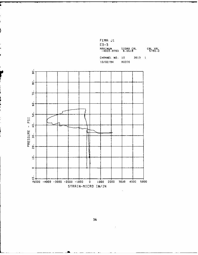
Complete data records obtained for the three tests are presented in this
appendix. For gage locations refer to Chapter 2 of this report. Tensile
strains are positive, and compressive strains are negative. Water pressure is
referenced on the ordinate.
For Test JD3 the following pairs of records are believed to be reversed:
EO-i, EI-I, EO-3, EI-3, EO-4, and EI-4.
Data plots labels are: J1 for test JDl, JD2 for test JD2, and J3 for test
JD3.
48

F*EMR $1SE-I
Mglg TDMR JAL CAL VAL. 6 1 .4875 74.2
CHANNEt NO- 15 3133 1
10/10/84 R0450
LU
ui)c.
03 -------- __
20 30 40. ~C 6. 7. 9. 90
FRESSUFF - PSI
49

FEMR JISE-2MRXIMU92 S[GMR 72L CS eL
CHRNNEL. NO. 16 3613
10/10/84 R0450
coC -
0 5. 10. is. 110. 115. 30. 35. 40. 45. so.PRESSURE - PSI
50

F EMq J 1", -I
MqXIMUM ET Mq CRL CAL VAL-"350 5333 0,722 148C.0
CHqNNE! NO- 3513
10/02/94 R0370
C,
(D
C;
.1
CL C3-
J2500 -2000 -1500 -1000 -500 0 500 1000 1500 2000 2500STRAIN-MICRO IN/IN
51

F EMR JI
ilci I U ,c q C "i1qXlMUrl 51Cri~R CR . CR.. VR.626 .6663 .3969 578CC
CHqNNEU NO. 9 35',3
10/02/94 R0370
C" I I
o 1-r)
C) .... . . . ..
I
u
D C
U-)iu
rj
0 - _ _ =,
L100 0 100 200 300 400 500 600 700 So0 900
STRRIN-MICRO IN/IN
52
t !~~~~~~1 .. ........... . . . . .. . . . . .. . . . .. . . . . .

FEMR JIEI-2MAXIMUM SIOMA CAL CAL VAL2032.7857 4.2144 5780.u
CHANNEL NO. 7 3613 1
10/02/84 R0370
co
0 -/
p _
0-w -- -/ I(L
0
C 500 1O00C 1500 2000 2500 3000 3500 4000 4500 5000
STRAIN-MICRO IN/IN
53
.126
LI
| L .. . . .. . ..
FEMP JI
EO-3M S IGMA CRL CAL VAL-4 2 .97 63 6.0518 5780.0
CHANNEL NO. 10 3613 1
10/02/84 R0370
a-,
__ _ ___3_ _ _ _
Lo_____ ______I______ _____
0-
0* _ _ _ __ _ _ __ _
c;
C50. _400 -3'0-60___ 6 10 OC 0U 4'050
(0RNMCR NI
054

FEMP JIEI-3
~~L8 S I SG?4R CL CAL A
CHANNEL NO. 9 3513110/02/84 R0370
0 __co
_______________ _______r___;____ _______ _______ _______
C,
____I____ ____ ___ ___ ___
V)
LUJi 0 - _ _ _ _ _
0-
-'2000 0 2000 4000 6000 80'00 10000 12000 14;00 16000 18000
STRAIN-MICRO IN/IN
56
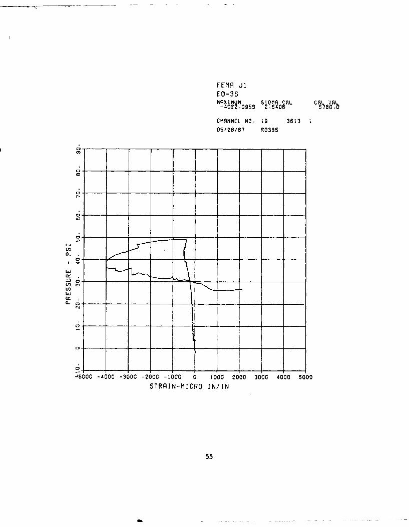
FEMR JI
EO-35mqxmo.5 si~morAL CA7 VA,-40 2.095 .64060.
CHANNEL NO. iS 3613
05/29/87 R0395
r,
~0
.0
0,
w
ITAI-MCRII/I
c;u-i
U) e
-'SOOC0 -460 -3000 -200C -1000 0. 1000 1-000 300 40'00 500
STRAIN-MICRO IN/IN
55

FE11A JIEI-3SM-44M1 SI37 tf3 CAL CAL VA1 43u -67 TA6 0
CHANNEL NO. 18 3613 105/28/87 R0386
LO
0:
2aO 40C60____ oc 26Ci6016C 90
STR"UA'R I
n 57
M L, .... ..

FEMA JiEO-4MAX 5 MU S[MA CnL C% LAI19U3239 1.621 840.I
CHANNEL NO. 12 3613
10/02/84 R0370
0;0,
c;
0 _ __ _ __ _ __ _
LuJ
(if __ _ _ _(( c
(2 00 0 20 40 60 80 10 20 10 60 IC
STRNMCR NI
058

FEtIA JIE I -4
MUM~ 32nL CR- V i(5152s~ .8M968 .53 578.
ClHqNNCL NO. 1 1 361305/28187 R0393
0 -
C;
Ci
no.
C;,
_J1OO0 0 1000 2000 3000 4000 5i000 6000 J7000 600 900STRRIN-M'ACRO WNIN
59
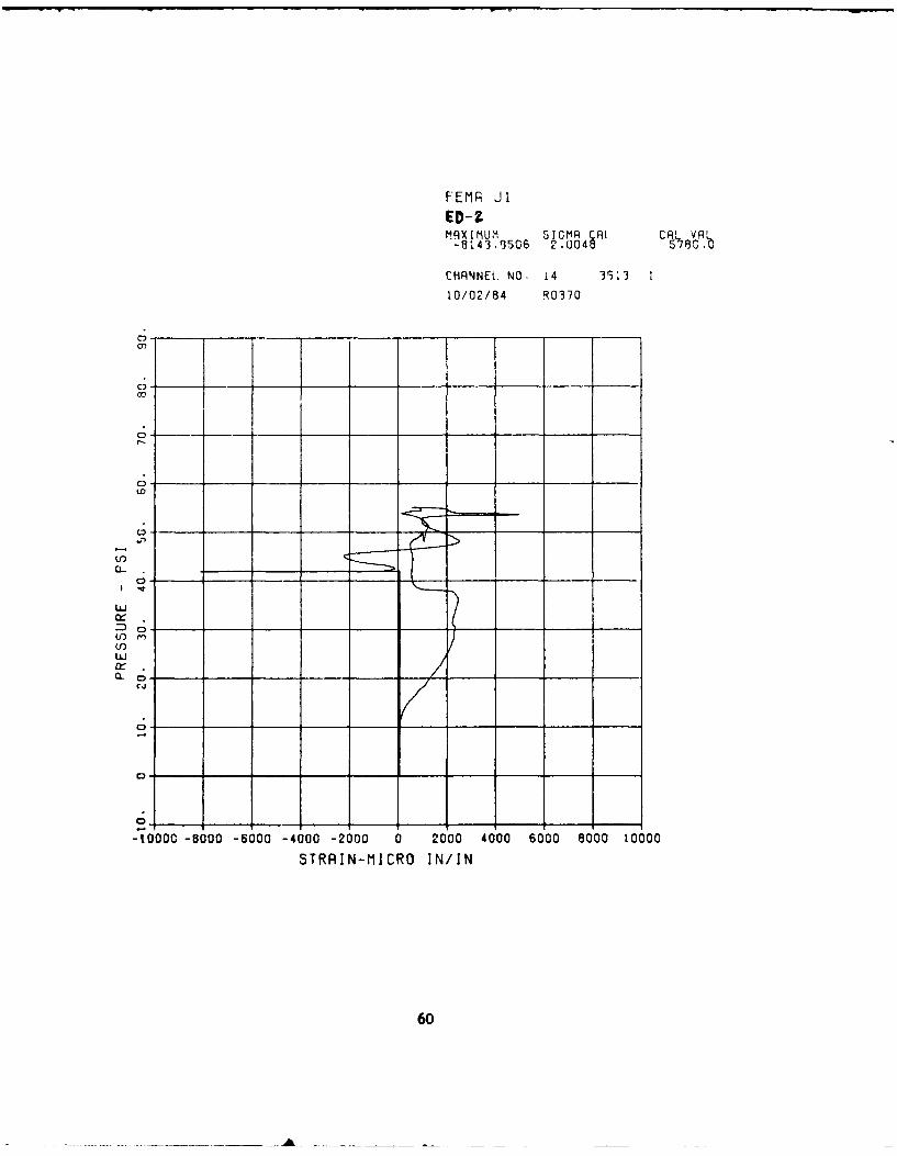
FEMR JIED-?.MAXIMUM SIGMA CAL CAL VAL-8143.9506 2.U048 578c.0
CHANNEtl NO. 14 3 3 1
10/02/84 R0370
c;
c; ,
0
'fl
-10000 -8000 -6000 -4000 -2000 0 2000 4000 6000 8000 10000
STRAIN-MICRO IN/IN
60
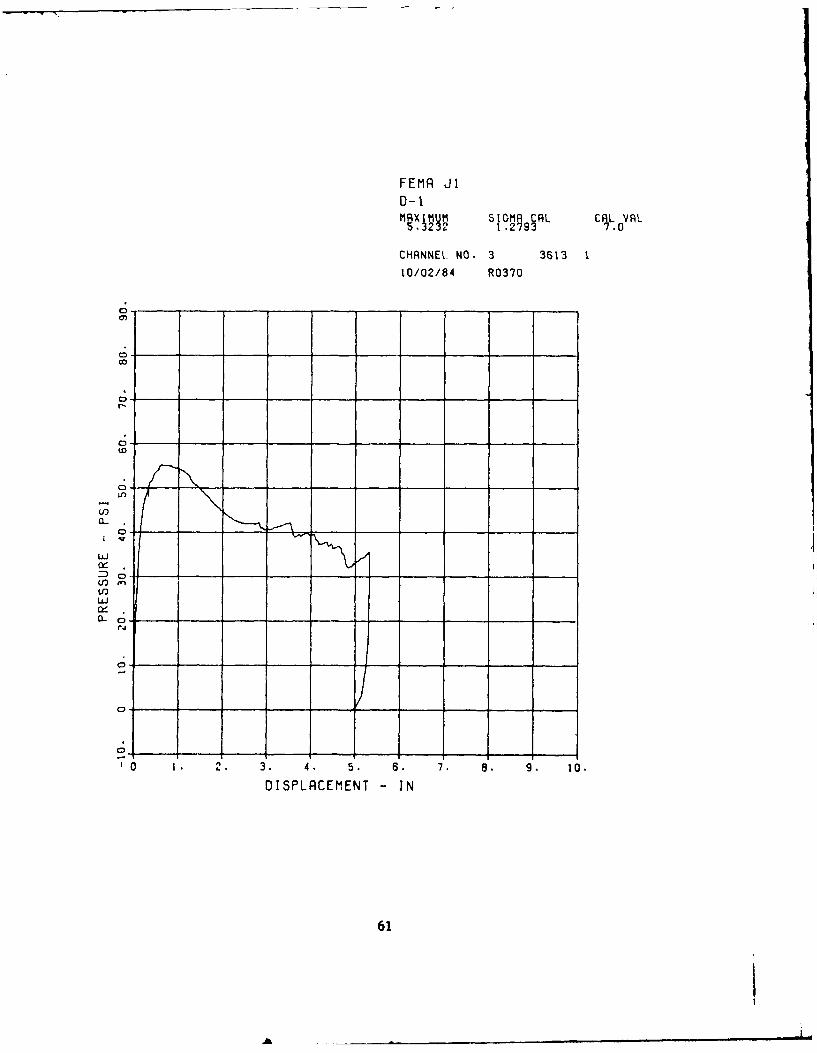
FEMR JID-1MgXj SIGM 9CAL CRL VRt
-1 .273 0
CHANNE. NO. 3 3613 1
10/02/84 R0370
0
C"
00
V)a-
LuJ
C ___
U)LOLUJ
0 ... ..__ __
'0 1. 2. 3. 4. 5. 6. 7. 8. 9. 10.
DISPLRCEMENT - IN
61
I

FEtIR JI0-2MAX0 MU 5JGM A AL CAL VAL3.14 03 .
CHANNEL NO. 4 3613 1r10/02/84 R0370
(L c
U)
CL C
c;J
0-- - - )
'-0.5 0 0.5 1.0 1.5 n~o 2.5 3.0 3.5 4.0 4.5
DISPLRCEMENT - IN
62

FEMA 10O2SE-I
41.7482 .48G . 114.0
3.1IC1 1. S A
(n
10.i 20._ 30____ CS
PRESSURE - PSI
63

SE -2MR11MUM, S CR1Z CAL VAL
CHARNWrL NW3 19 15344
OS/Oi!85 ROP6j7
0
40. ____j10 ; 4 . S 66 6 o
PRESSURE -- PSI
64

FE!1P J02
3 gO Si .612 2S 90
ClqNN[A. NO. 5 15544
U-j
a,4/
5- _'_ I I _N _ _
65

FE.'i4 J32
26 - &" S
CPANNEL N.O, 5 15644 1
03/01,185 R0601
In
-0 3 5 o 0 20 30 5 5
SILIN M CR I
C-6

fE 0 2
09 - -O f 3 ~
Lu
L c tj
-130. -SQ.* 0 53 00 .D 200 O. ICC' 35O0 - 00
5TRR!N-MICRO WNIN
67

- No
LEC JJ
E. 1 -
MCXMU il" CLi
**u.il 3.33 9~~
a,~i~ N
20 0
10 00 3(50-0 30 20-0u-J!NMLR I
C6

U.- - 3MR I mum 5U1~ ct L CAL VAL
5S.92.3350 3 .3 i36 78.
CHR\'NCL NO. -O 3'
.q
C3
I r'j
C-,)
uJ
-100C .000 O c30o0 .O0. o c ou. 0 s9000cgo-
69

FEMq j02
MAX jMUM 38 SIGMA CAL CAL VAL
CHANNEL NO. 9 iSS44 I
Lin
C3
.1
LA
uj
w30___
C,
4 O tS O CC S - SZ OOO 1 260- ',4k- .PGOC '1800 2OCC-
SIRAI!N-MICRO WNIN
70
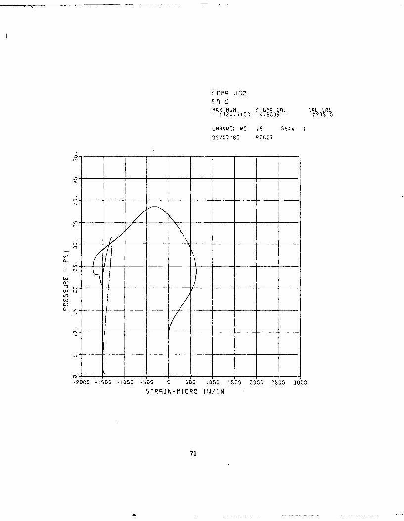
NqImum1 SI(Iq CAL CA~L VPL
.. 724 -71031 4.5O-) 0
CHPNI,"X NO .5 1544
O5/07'85 ROFiC-1
In
iJ
t.) J
-200. -1500 -1 U3C b 00 00 O3 C S0 203' 2' O3 3 00
51RqIN-MICRO WNIN
71

FE~1q J 2
5 1 0 596 3.5303 9
rHANNEL NO- 30 15544 1
03/07,85 a r,
Ln
In
01-
I.)
C
010 ; OCS 200SC 300C 4000 'JODO 6 Z '3 105S~ 9030
51'RCIN-MICRO MNIN
72
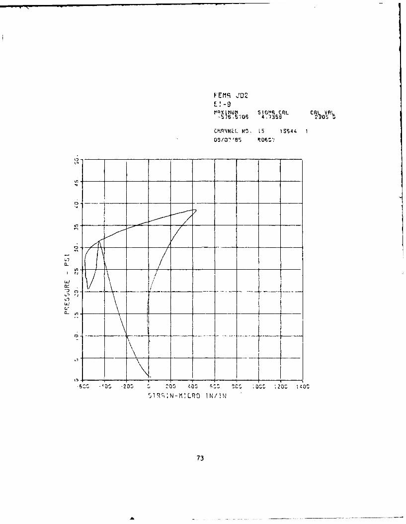
VEMR J02
E! -9
s S.S; 4.33 SO
CH.PNEL. N3. is 155441
n-
U-1
LD
C S 11 2 l S S 20 I
73

FEMRi J02
M x m u m S I C'OSL M I t
132S900 . 5785.~
CPHANNEL NO. 2 9 S4
OS/01'85 R0 63'7
1,- ___ ____ ____ ___ ___
CL:
-200 _0___31 oo; M .0 3z 3
510'; - ' P I
U., __74

F Ex I mu , s ;4 :F.
44033-393 3 -0S5) 43cC -
u
CC
.. 10OSz -505Sz ' tjj0Z-OZC :500-4 20S- 2OOS 330-.- 3$00tZ 4O0-Z
3'Rc2.N-ICRO WNIN
75

MRX IMUM S!G.mq CnL PLP.
P~LNO .2 5ri
03/075 rss Of-)
C-
uLJ
-1030 * u c 40 C 1 SG 2000 -1500 3000 2S00 40-
SIRR!N-MICRO WNIN
76

FE~1q J32
E.-6n
3: 4 -27 3 K8527 45
,HPNNEL NO. 2 155i44
03/01135 OC
I ci
-j
uLJ
CL U
0 1011 20E.* 30D 403 !U:& 6-: o 90 ~O93 10DC
riTRrN-MCP IN/:N
77

FErq JG2E -7MrI1mum SIGMq CAL CPL VAL-4635..3136C 4.- 221
CHRN'NEI. NO. 13 15644 1
D~Osi.'85 RO0S 07
,7
UI-1
0-n
13.) '
STROC:N-MICRO WNIN
78

FE~q Jr,2
U,~1 -. _
33c -_____ 6 3__ .405r, ___t
Ca-.1Wei
0 _ _ _ _ _ _ _ _ _ _ _ _
u-i
C_ n
350-300S -2SOO -200% 1500 -~j^, ASQu 1C, oo
S'PRq!N-ICP' WNIN
79

F EfI JC2
L - 8PIX IM mum ~ tGR CAL CAL2 VARLM121.3026 3.5311 S796.3
09/Vlo '85 R060V
L A
LA
W
ci-
08

FE~q J02E -SB
MXMUM SIU?4R rAL CQL VA.L23 139.759b -1-5,3.
CMQ9NWEL. NO. 8 IW54 I
Cn - .- ___
In _ _
ui
u-i
JuCC 0CS' :C O 500', 2OSCZC 2500SZ 30000 2SOZC0' 4'0OCC 4bO0C
51 R; : N-M : CR IN/I N
81

FEMP J02
SAL~~R CRL .fRL
CHR14NEL NO. it 15544
LM
0 _ _ _ __; _ _ _ _
0 -
DISPLRCEMEN1 -IN
82

0-2?mqxI mum I m c CPA 'L VAL
3 i3i 5 2195 4 3
CMRPNNCI. NO A
kn.
0a --.
7: C3J
uJ
IjIN
C83

FEMR J3SE-1MAXIMUM 3IJMR CRL CAL VAL73.3341 1., 74 74.2
CHANNEL. NO. F5 1.55i
06/135/4 R0423
C3
0 __
C, ____/
C; 'zf
O 10. 1O0 - O0 40. tp0. 60. 70o . 96. g. lOO.PRESSURE - PSI
84

FEMR J35E-2
JRSA L C%1 VRL
CHANNEL. NO. i6 1505i
08/13/84 R0423
0
0-
0 -
(C
(:2
L
o 0. CIO 30. 40. 50. so. 70. so. .36. 1oo-PRESSURE PSI
85

FEMA J3
t1AX1!1R C 1 S4L CAL VALMAXIIMPM579 13is5780.0
CHANNEL. NO. 5 1505i
06/13/84 R 0423
0 c _ _ _ _ _ __ _ _
C,
a-C;
C.
c;
20 - 10 -1000 -500 0 _ 10 _O 60 , o 3
STPNIR WI
U86

FEMR J3E 0-1 5MqXIMUM jIGMRL CRL VRL1557 S42b ..$S 7 -
MHqNNEI NO. i7 1505 i
09/13/94 R0423
C,o
Z)
CL C0
-2000 -1,00 -1600 -5'00 0 500 10'00 1-500 2000 2b00 3000
STRAIN-MICRO WNIN
87

FEMR A3
289 1 450.0CR
CI1RNNEI. NO. 5 l1505i
06/13/94 R0423
C;
(C'
C;
1-0u6030 0050 60 00 0090 00STRIkICOINI
p.88
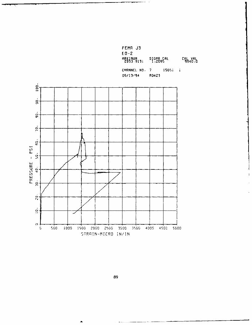
FEMR A9ED-2MRX1 MUM,, SGR~RL C429~ 39 .3 CZaV9AI
CHAWNL. NO. 7 1505'i
05/13/94 R0423
C,
cc~
IG 0 ,OG 0 -0-0 -Lb 'MG3rrG 4000 450 500,
'jTRRIN-f1ICRO IN/IN
89

FEIIR J3EJ-2"JjAX 3 II1f iI gIBCRL cP44VA1
CHRNNEL. NO. 8 1505106/13/84 R0423
61%
LO-w
uLJ
w
0-
-400 -200 0 200 400 %0 ' 00 1000 1200i i 1400 1600
STRRIN-MICRO WNIN
90

FEMR J3E:O-3MR XIU IG1R CAL CAL VAL151b42..3)22 1 .6345 1340,0O
CHRNNEt NO. 9 1505i
06/13/54 R0423
c; -
c;
0
U')a-
Uw
c;
-2000 0 2000 4000 6000 9000' 10000 12000 14000 16000 18000
STRAIN-MICRO IWIN
91

FEMR A3E 1-3-M"TV7941 07IA A
CHANNEL. NO. iO 1sori
06/13/94 R0423
0 - ---
0; - --
CL
Lo
LUL
-2500 -2000 -1500 -1000 -500 0 500 1009 1500 2000 2500
STRRIN-tIICRO WNIN
92

FEMA J3EI-35 ~ S4~L C~~ 0 L
04 -- ____
0; -
c0 -
0;--
,j
c;_
-30 o 2o 20 10 10 0 ) lo So 2
STANMIR0I
U)93

FEMR J3EO-4
MAX IU I SIGM4A CALM-4PYZ 0574 1 .639 se
CHANNEL. NO. I 1505,i
06/13/04 R 042 3
0
450-00-30 -300-50-00-50-06-0 o
STR-- - -ROWI
C94

FEMR J3E!-4
CMHNNEt. NO. 12 Iso15 506/13/84 R0423
0-
CP
02
CL .
U,
0-
0 200 400 600 900 1000 1200 1400 1600 1100 2000
STRAIN-MICRO IN/IN
95

FEMI J3ED-I
CIIRNNEI. NO. 13 l55i06/13/84 R0423
0;---
0
= j
4-
-500 0 Soo 1000 1500 2O00 2500 3000 3500 4000 4500
STRRIN-MICRO WNIN
09

FEMSA J
"RUM7603 .67508R gP~Ro
CHANNEL. NO. 14 15051
06/13/84 R0423
0 -
U)
aL-
100000 - -00 0 0.O 00 50 400 C10 00 50
STRNIIR WIN
LA97

FEM1R J30- iflJMfl 51pXjf C7.0V
CHANNEL. NO. 3 1505i
06/13/84 R0423
0;-- - _
0 6, - .5 2. . . .5 4-, it. .
DIPAEET -I
098

FEIIR J3D-2
9" 4.3
CHRNNEL. NO. 4 1505i
08/ 13/14 R0423
a -
a;
o -3
IL -
I'
DISI'LACEflENT -IN

DISTRIBUTION LIST
Director. Federal Emergency Management Agency Los Alans Scientific LaboratoryATTN: M~r. Tomn Provenzano (6 Cye) ATTN: Report Library MS-364
500 C St. S PO Box 1663
Weeb shat6. DC 20472 Los Alamos. N. max. 67544
Comder. US Arm Regiser District. Viluingtok. Director. Ballistic Research Laboratory
ATII: Pat Imme/ribrary ATTN: (DRZIU-TBD/Nr. Ceorge Coulter)
PO box Is" Aberdeen Proving Ground. Md. 21005Wlmiaglte.. II. C. 26403
Commanding Officer. Office of Naval Research
Headquarter. Dep prtment of Energy Department of the NavyATTN: Ltbrary/G-049 MA-232.2,Th Uaehlngcn, DC 2030
Vahington, DC 20345Commanding Officer
National lureau of Standards US Navel Civil Engineering Laboratory
ATTN: Mr. Samel Kromer Naval Construction Battalion Center
Dr. Leowi V. Spencer ATN: Library (Code L08A)
Wshington. DC 20234 Port iuenes. Calif. 93043
Aseociate Director. Natural Resources and Commander. Air Force Weapons Laboratory/SUL
Commercial Services ATTN: Technical Library
Office of Science & Technology Kirtland Air force Sage. 0. Mas. 87117ATTN: r. Phillip N. Smith
Executive Office Building Civil Engineering Canter
Washington, DC 20500 AF/PRECETTyndall AFU, Fla. 32403
Director. Office of Administration
Program Planning and Control University of Florida
Department of Housing and Urban Development Civil Defense Technical Services
ATTX: Mr. Sart Greenglais College of Engineering
Washington. DC 20410 Department of EngineeringGainesville. Fla. 32601
Director. Defense Nuclear AgencyATTN: SPMD/Mr. Ton Kennedy Technical Reports Library
STTL/Tchnical Library Kurt F. Wendt Library
Washington. DC 20305 College of EngineeringUniversity of Wisconsin
Director. Defense Intelligence Agency Madison. Wisc. 53706
ATTN: r. Carl Wiehle (DB-4C2)Washington. DC 20301 Agbabian Associates
250 N. Nash Street
Assistant Secretary of the Army (R&D) El Segundo. Calif. 90245ATM: Assistant for Research
Washington. DC 20301 AT&T Bell LaboretoriesATTI: Mr. E. Witt
Office. Chief of Engineers. Whippany. N. J. 07931Department of the Army
ATTN- DANU-DZ-A Joaes E. Beck 4 Associates
DAEN-ECE-D 4216 Los Pales Avenue
Washington. DC 20314 Palo Alto. Calif. 94306
Sandia Corporation Chamberlain Manufacturing Corp.
ATTM: Dr. Clarence R. Mehl GAD. Inc.
Dept. 5230 7449 N. Macchas Avenue
Box 5800. Sandia Bse Miles. Ill. 60648
Albuquerque. N. ex. 67115ITrT Research Institute
Director. US Army Engineer Waterways A" : Mr. A. Longlnow
Experiment Station 10 West 35th Street
ATTM: Dr. S. A. Kiger Chicago. Ill. 60616
Mr. 6111 MuffHr. Stan Woodeon H. L. Murphy Associates
Hr. Tom Slavon lox 17275 cys Library San ats. Calif. 94401
PO Box 631Vicksburg. Nice. 39160 RAND Corporation
ATTN: Document Library
Defense Technical Information Center 1700 Main Street12 cy ATM: (DTIC-DDA/Mr. Myer B. Kahn) Santa Monica. Calif. 90401Camero StatisoAlexandria. Va. 22314 Research Triangle Institute
ATT: Mr. Edward L. Hill
Commnder. US Army Materials and Mechanics PO box 12196
Research Center Research Triangle Perk, N. C. 27709
ATIat Technical Libraryetergtm, Now. 02172 Sciantific Services. Inc.
517 test Bepahore Drive
Comnd ad Control Technical Center Redwond City. Calif. 94060
Department of DefeReam 29312 Imtages US Army ta4ineetr Division. Huntsville
VeWftimm. VC 20301 ATN: r. Paul Lahoud (10 Cys)PO oa 1600. vest Station
Oak Ridge astmmal Laboratory Huntsville. Ale. 35807AIIMI Greg Zimmerme
Ceowsd MasterOA Ride. Tom. 37131
100

Fm t 4! -a s A td to v
o w o. 41 IWms v . v 2 S . o. c oc o g-tk.
L o V W w o
o 8 P. Id
P. o 1. 41 v o $X 4. 40 o o, 4) o-mo,
A v "I14 o o a w ! i ,r o
41 .ou 1
Voo t It, it v o1; -as lo N All ok ot
a v w a o92 2 , a .jo r
o > lo Iv E's ole 4.u - 9 c v
. 'd lo4c- o' z t
o 44, o .11 oa y , u 9 V V Wo w v v o -c A c m o tD v a G
t +1 o 6E 1; u v I I v L v v w o,
c to_Q. d v 41 w o. m E-c d o m v I 1 41 .0 o o I t, Im w 1 6
a to's w oo r d I Q " 'Wa Nc m c-; 'i o w c 4, -1 -c c
o zo m i o C
I vw lu 11 E 0 'loll 11 C ,d 0 V 41 10o r
E-d =
OC cw I wo co v o--o o o 4, c o o
a w oIca I. S I. o o-
o o d V V 41 0 0 1 V A 11 V "I C 0 0 0 11 41 4' v oo v f . c
v - . , - 5 o ol v s v a -o mt,I P. o w
ev ", uo o a, 8 a cL 't41 S. o m
o o o t v5 c 0,, 8o x 41 o
E4 'o
41 s 41 E- E-W - i L d' C
- p a ! d R *1 'o
o 41Da r Q
El41 w
E- oo Q oa o 41w M Q C
o 1, 0 Cd wv lo 1, a*c o 61D -. ,
"I I 8 A tt41 Id V
oo
o Z.9 lo c r. 41 v r 11 zo-I I
IL o -1 o t K 0 -
oo > .to u , - - x c
v4) d a jd 16 v
p_R
a in oLIP 11 E .0
IL-S . 2 14c, Q w t x o C7 o o
1) = I 1=1 a C, v *8c o.. v 0 .
o >4, F
10 m to 4
1 0 v I : 0 1 c to -ol z V m t ua v - a -a V d C 0 4D o I
_ *v Id v o 4. 19 0 v -1 4 " L. -- 0 o oru o
3. o o'o
a 45
t. w v v o
23- a a Iv6,1
:r6 o f. a -,,o o v to &
4, w o 4;c 6 w 6. Q* c' a v I = t 4, .A 6). r--o - , - 4, i I . , z I
-c a c , v S.
0 v tr oll o 1 4 S orovZ Q c Z c
RE S 2 u o o o c; P., lie I'll 9 o 11 o v occ a p o oz o . . . . . - . ! - t- " . 0 t4 * : z; - I a V t lo I, -o
a ao 3 -d 6 IL -4 e o 9 ; ;'o ." -. or o
m a 1. - 6 6. 0 c 6-- v v V
I-a o P. 0 :A A oL. o P. v rl 0 1
o
,c o R 2 IS o-I .1, -4 11 0o too f I t 'd 0
4.- 2 S. a v- o I o o 11uo a 6 4 a o 4, o- 41, Z;, 6 - o .06 v I t v0 t .
a I , 4 ". I . - -
i s 1 3-9 19 1 R 0- v c
o'a 0 all. 1 -. -ol 1 . 'a o 9 c
e 4 o-- A I a 3.