rzr® - ssv works · all ssv works enclosures are covered by a limited lifetime warranty against...
TRANSCRIPT
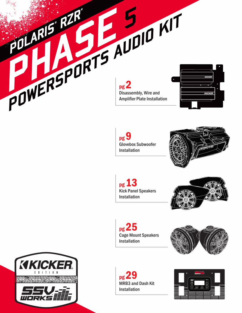
POWERSPORTS AUDIO KIT
PHASE 5POLARIS
® RZR®
Disassembly, Wire and Amplifier Plate Installation
Glovebox Subwoofer Installation
Kick Panel Speakers Installation
Cage Mount Speakers Installation
MRB3 and Dash Kit Installation
pg 2
pg 9
pg 13
pg 25
pg 29

2
3
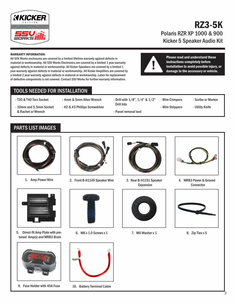
RZ3-5KPolaris RZR XP 1000 & 900 Kicker 5 Speaker Audio Kit
!Please read and understand these instructions completely before installation to avoid possible injury, or damage to the accessory or vehicle.
WARRANTY INFORMATION:All SSV Works enclosures are covered by a limited lifetime warranty against defects in material or workmanship. All SSV Works Electronics are covered by a limited 1 year warranty against defects in material or workmanship. All Kicker Speakers are covered by a limited 1 year warranty against defects in material or workmanship. All Kicker Amplifiers are covered by a limited 2 year warranty against defects in material or workmanship. Labor for replacement of defective components is not covered. Contact SSV Works for further warranty information.
TOOLS NEEDED FOR INSTALLATION- T30 & T40 Torx Socket
- 10mm and 5.5mm Socket & Rachet or Wrench
- 4mm & 5mm Allen Wrench
- #2 & #3 Phillips Screwdriver
PARTS LIST IMAGES
2. Front B-H1149 Speaker Wire
6. M6 x 1.0 Screws x 1
10. Battery Terminal Cable
7. M6 Washer x 1 8. Zip Ties x 5
1. Amp Power Wire
5. Direct-fit Amp Plate with pre-tuned Amp(s) and MRB3 Brain
9. Fuse Holder with 40A Fuse
3. Rear B-H1151 Speaker Expansion
4. MRB3 Power & Ground Connector
- Drill with 1/8”, 1/4” & 1/2” Drill bits
- Panel removal tool
- Wire Crimpers
- Wire Strippers
- Scribe or Marker
- Utility Knife
4
A
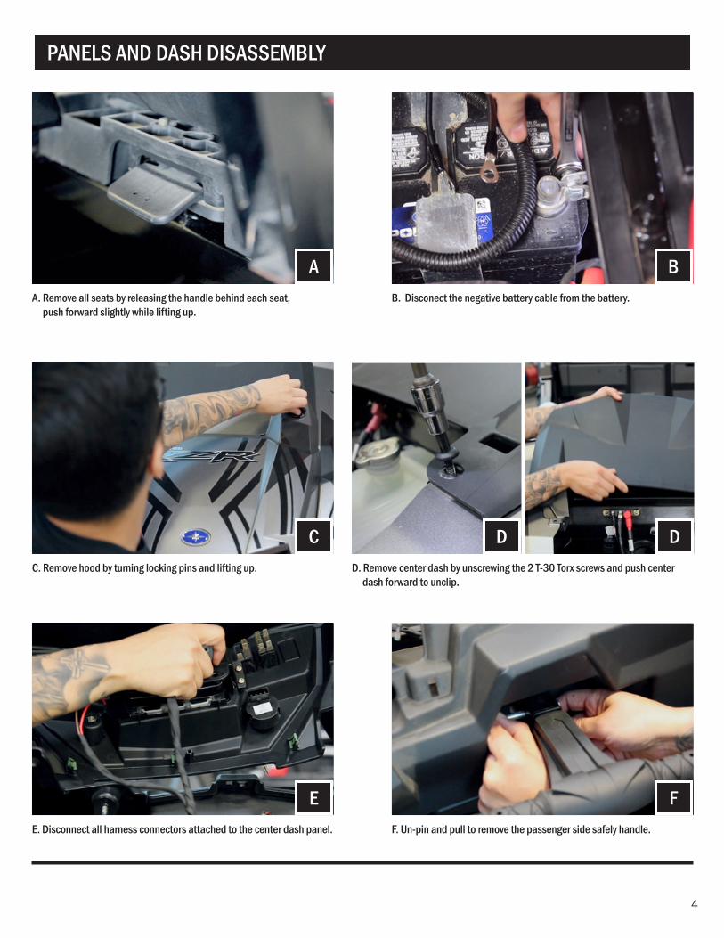
PANELS AND DASH DISASSEMBLY
C
E
B
DD
F
A. Remove all seats by releasing the handle behind each seat, push forward slightly while lifting up.
C. Remove hood by turning locking pins and lifting up.
E. Disconnect all harness connectors attached to the center dash panel.
B. Disconect the negative battery cable from the battery.
D. Remove center dash by unscrewing the 2 T-30 Torx screws and push center dash forward to unclip.
F. Un-pin and pull to remove the passenger side safely handle.
5
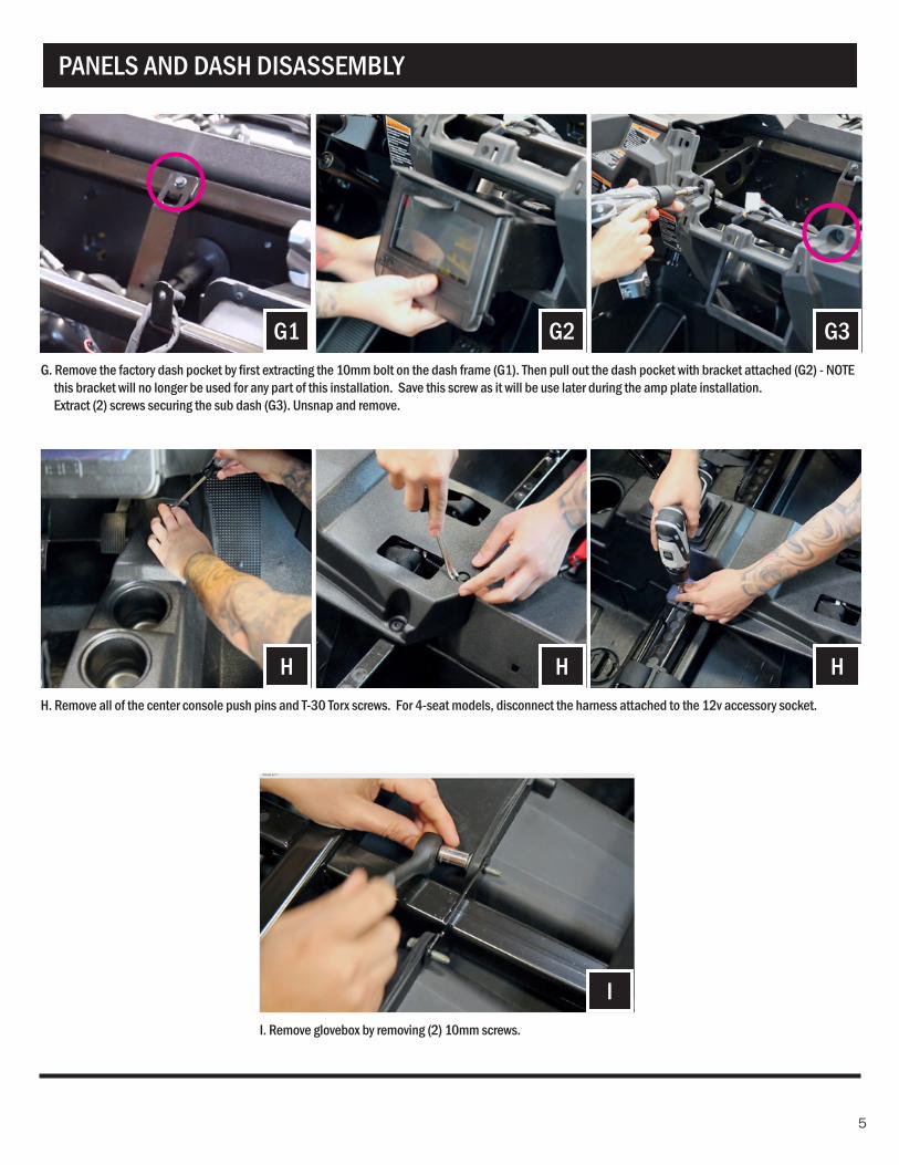
PANELS AND DASH DISASSEMBLY
G1
H
G2
H
G3
H
I
G. Remove the factory dash pocket by first extracting the 10mm bolt on the dash frame (G1). Then pull out the dash pocket with bracket attached (G2) - NOTE this bracket will no longer be used for any part of this installation. Save this screw as it will be use later during the amp plate installation. Extract (2) screws securing the sub dash (G3). Unsnap and remove.
H. Remove all of the center console push pins and T-30 Torx screws. For 4-seat models, disconnect the harness attached to the 12v accessory socket.
I. Remove glovebox by removing (2) 10mm screws.
6
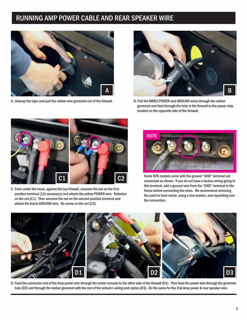
BAB. Pull the MRB3 POWER and GROUND wires through the rubber
grommet and feed through the hole in the firewall to the power strip located on the opposite side of the firewall.
A. Unwrap the tape and pull the rubber wire grommet out of the firewall.
RUNNING AMP POWER CABLE AND REAR SPEAKER WIRE
C2C1C. From under the hood, against the top firewall, unscrew the nut on the first
position terminal (12v accessory) and attach the yellow POWER wire. Refasten on the nut (C1). Then unscrew the nut on the second position terminal and attach the black GROUND wire. Re-screw on the nut (C2).
D1 D2 D3D. Feed the connector end of the Amp power wire through the center console to the other side of the firewall (D1). Then feed the power wire through the grommet
hole (D2) and through the rubber grommet with the rest of the vehicle’s wiring and cables (D3). Do the same for the 2nd Amp power & rear speaker wire.
NOTE
Some RZR models come with the ground “GND” terminal not connected as shown. If you do not have a factory wiring going to this terminal, add a ground wire from the “GND” terminal to the frame before connecting the wires. We recommend removing the paint to bare metal, using a star washer, and repainting over the connection.
7
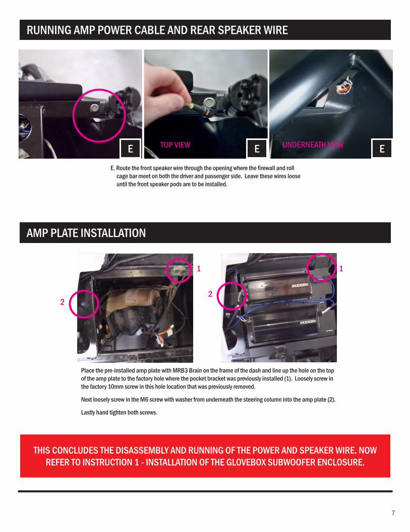
RUNNING AMP POWER CABLE AND REAR SPEAKER WIRE
AMP PLATE INSTALLATION
THIS CONCLUDES THE DISASSEMBLY AND RUNNING OF THE POWER AND SPEAKER WIRE. NOW REFER TO INSTRUCTION 1 - INSTALLATION OF THE GLOVEBOX SUBWOOFER ENCLOSURE.
E E EE. Route the front speaker wire through the opening where the firewall and roll
cage bar meet on both the driver and passenger side. Leave these wires loose until the front speaker pods are to be installed.
Place the pre-installed amp plate with MRB3 Brain on the frame of the dash and line up the hole on the top of the amp plate to the factory hole where the pocket bracket was previously installed (1). Loosely screw in the factory 10mm screw in this hole location that was previously removed.
Next loosely screw in the M6 screw with washer from underneath the steering column into the amp plate (2).
Lastly hand tighten both screws.
TOP VIEW
11
22
UNDERNEATH VIEW

8
9
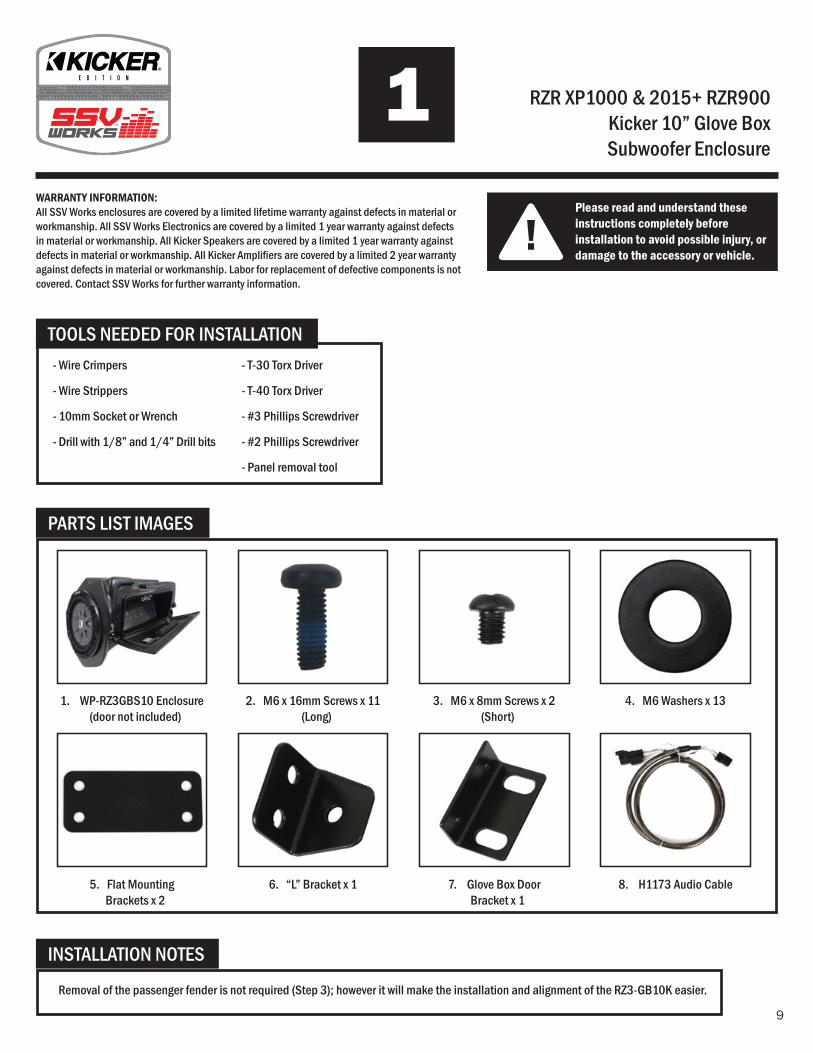
RZR XP1000 & 2015+ RZR900Kicker 10” Glove Box Subwoofer Enclosure
!Please read and understand these instructions completely before installation to avoid possible injury, or damage to the accessory or vehicle.
WARRANTY INFORMATION:All SSV Works enclosures are covered by a limited lifetime warranty against defects in material or workmanship. All SSV Works Electronics are covered by a limited 1 year warranty against defects in material or workmanship. All Kicker Speakers are covered by a limited 1 year warranty against defects in material or workmanship. All Kicker Amplifi ers are covered by a limited 2 year warranty against defects in material or workmanship. Labor for replacement of defective components is not covered. Contact SSV Works for further warranty information.
TOOLS NEEDED FOR INSTALLATION
INSTALLATION NOTES
PARTS LIST IMAGES
Removal of the passenger fender is not required (Step 3); however it will make the installation and alignment of the RZ3-GB10K easier.
2. M6 x 16mm Screws x 11 (Long)
7. Glove Box Door Bracket x 1
8. H1173 Audio Cable
3. M6 x 8mm Screws x 2 (Short)
4. M6 Washers x 13
5. Flat Mounting Brackets x 2
1. WP-RZ3GBS10 Enclosure (door not included)
6. “L” Bracket x 1
- Wire Crimpers
- Wire Strippers
- 10mm Socket or Wrench
- Drill with 1/8” and 1/4” Drill bits
- T-30 Torx Driver
- T-40 Torx Driver
- #3 Phillips Screwdriver
- #2 Phillips Screwdriver
- Panel removal tool
10
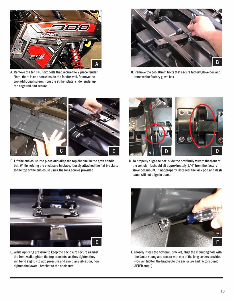
C. Lift the enclosure into place and align the top channel in the grab handle bar. While holding the enclosure in place, loosely attached the fl at brackets to the top of the enclosure using the long screws provided.
A. Remove the ten T40 Torx bolts that secure the 2 piece fender. Note: there is one screw inside the fender well. Remove the two additional screws from the striker plate, slide fender up the cage rail and secure
E. While applying pressure to keep the enclosure secure against the front wall, tighten the top brackets, as they tighten they will bend slightly to add pressure and avoid any vibration, now tighten the lower L bracket to the enclosure
D. To properly align the box, slide the box fi rmly toward the front of the vehicle. It should sit approximately 1/4” from the factory glove box mount. If not properly installed, the kick pod and dash panel will not align in place.
B. Remove the two 10mm bolts that secure factory glove box and remove the factory glove box
F. Loosely install the bottom L bracket, align the mounting hole with the factory bung and secure with one of the long screws provided (you will tighten the bracket to the enclosure and factory bung AFTER step J)
D
A
C D
E
C
B
F
11
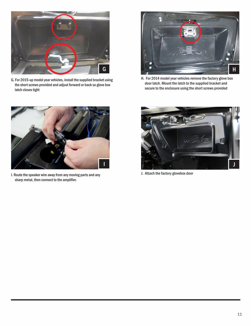
G. For 2015-up model year vehicles, install the supplied bracket using the short screws provided and adjust forward or back so glove box latch closes tight
GH. For 2014 model year vehicles remove the factory glove box
door latch. Mount the latch to the supplied bracket and secure to the enclosure using the short screws provided
H
I. Route the speaker wire away from any moving parts and any sharp metal, then connect to the amplifi er.
IJ. Attach the factory glovebox door
J

12
13
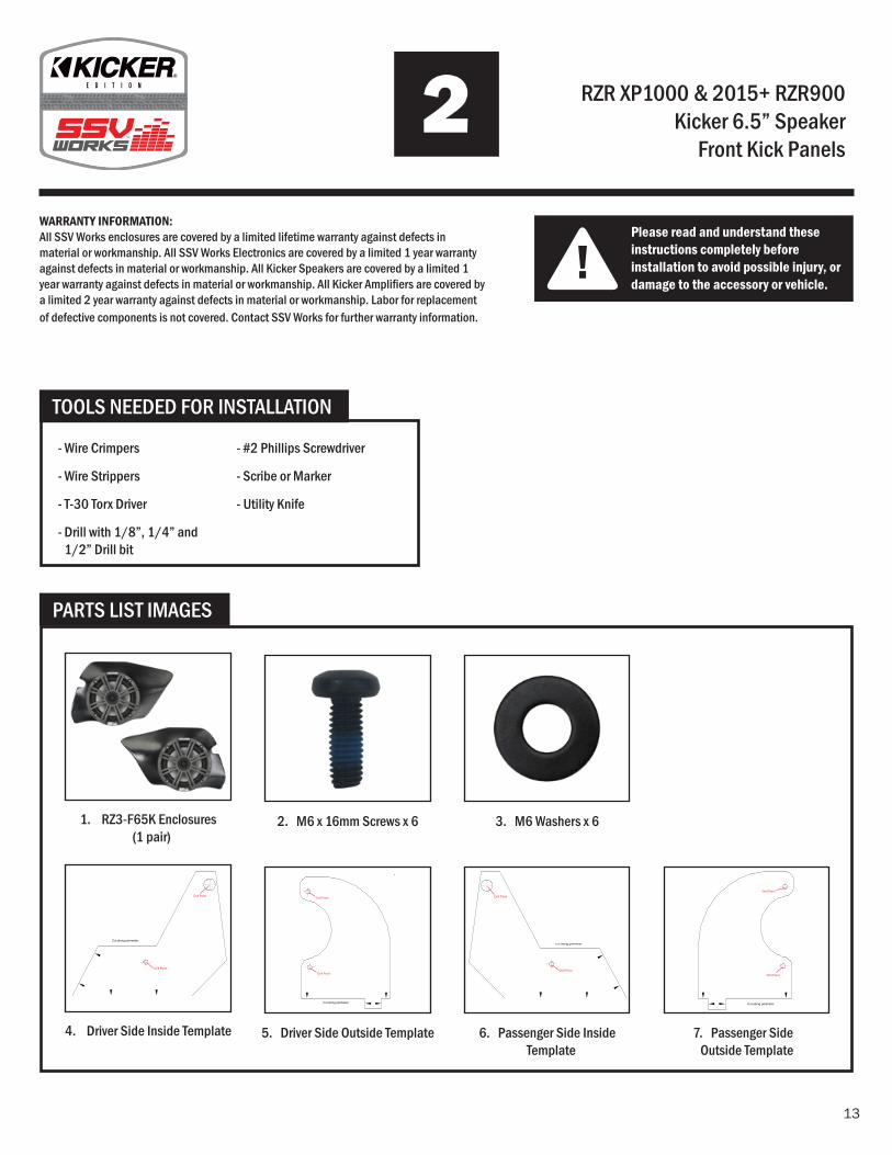
RZR XP1000 & 2015+ RZR900 Kicker 6.5” Speaker
Front Kick Panels
!Please read and understand these instructions completely before installation to avoid possible injury, or damage to the accessory or vehicle.
WARRANTY INFORMATION:All SSV Works enclosures are covered by a limited lifetime warranty against defects in material or workmanship. All SSV Works Electronics are covered by a limited 1 year warranty against defects in material or workmanship. All Kicker Speakers are covered by a limited 1 year warranty against defects in material or workmanship. All Kicker Amplifi ers are covered by a limited 2 year warranty against defects in material or workmanship. Labor for replacement of defective components is not covered. Contact SSV Works for further warranty information.
TOOLS NEEDED FOR INSTALLATION
PARTS LIST IMAGES
2. M6 x 16mm Screws x 6
5. Driver Side Outside Template
1. RZ3-F65K Enclosures (1 pair)
4. Driver Side Inside Template
3. M6 Washers x 6
6. Passenger Side Inside Template
7. Passenger Side Outside Template
- Wire Crimpers
- Wire Strippers
- T-30 Torx Driver
- Drill with 1/8”, 1/4” and 1/2” Drill bit
- #2 Phillips Screwdriver
- Scribe or Marker
- Utility Knife
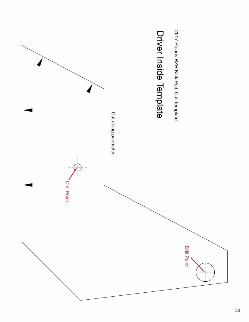
RZ3-F652017 Polaris RZR Kick Pod, Cut Template
Driver Inside Template
Cut along parimeter
Drill Point
Drill Point
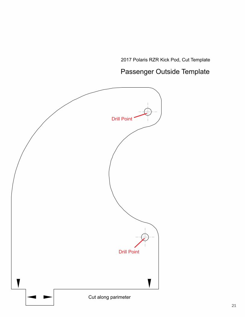
RZ3-F652017 Polaris RZR Kick Pod, Cut Template
Passenger Outside Template
Cut along parimeter
Drill Point
Drill Point
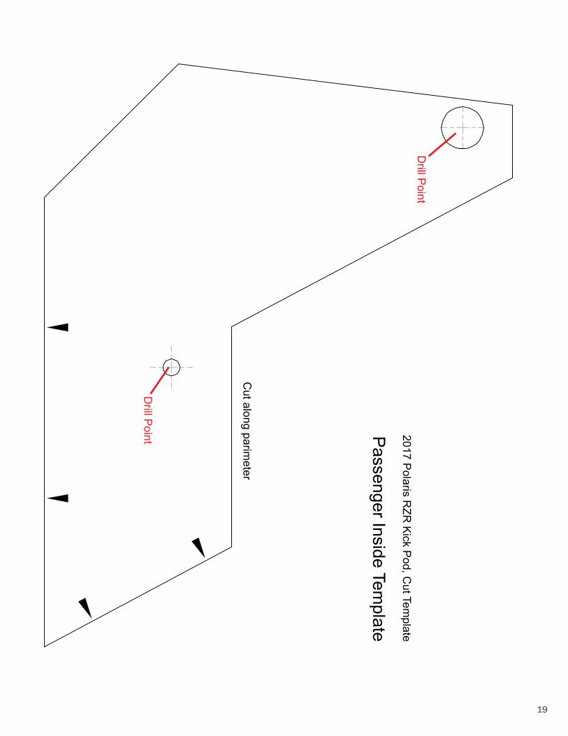
RZ3-F652017 Polaris RZR Kick Pod, Cut Template
Cut along parimeter
Passenger Inside Template
Drill Point
Drill Point
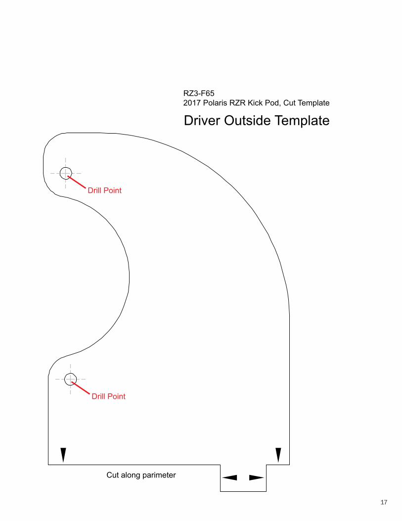
RZ3-F652017 Polaris RZR Kick Pod, Cut Template Driver Outside Template
Cut along parimeter
Drill Point
Drill Point
14
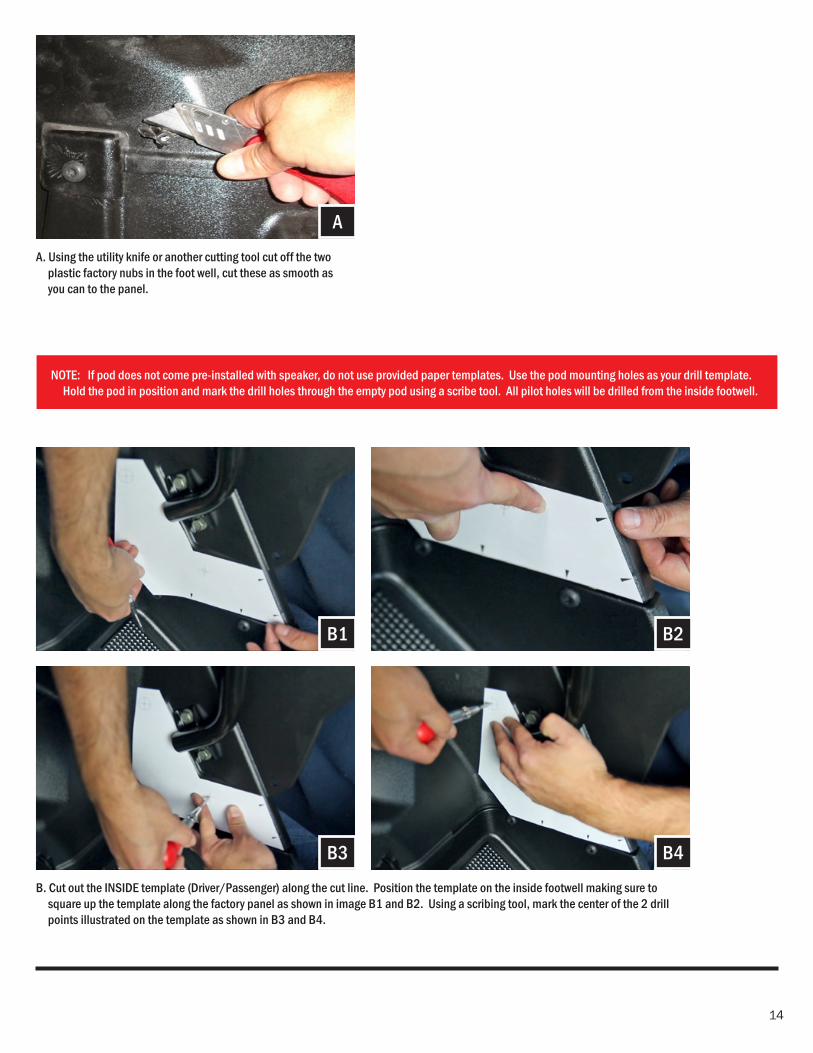
B. Cut out the INSIDE template (Driver/Passenger) along the cut line. Position the template on the inside footwell making sure to square up the template along the factory panel as shown in image B1 and B2. Using a scribing tool, mark the center of the 2 drill points illustrated on the template as shown in B3 and B4.
A. Using the utility knife or another cutting tool cut off the two plastic factory nubs in the foot well, cut these as smooth as you can to the panel.
B1 B2
B4B3
A
NOTE: If pod does not come pre-installed with speaker, do not use provided paper templates. Use the pod mounting holes as your drill template. Hold the pod in position and mark the drill holes through the empty pod using a scribe tool. All pilot holes will be drilled from the inside footwell.
15
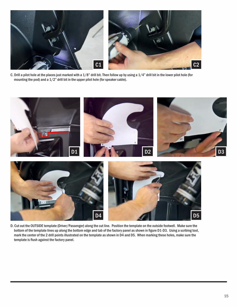
D. Cut out the OUTSIDE template (Driver/Passenger) along the cut line. Position the template on the outside footwell. Make sure the bottom of the template lines up along the bottom edge and tab of the factory panel as shown in fi gure D1-D3. Using a scribing tool, mark the center of the 2 drill points illustrated on the template as shown in D4 and D5. When marking these holes, make sure the template is fl ush against the factory panel.
C. Drill a pilot hole at the places just marked with a 1/8” drill bit. Then follow up by using a 1/4” drill bit in the lower pilot hole (for mounting the pod) and a 1/2” drill bit in the upper pilot hole (for speaker cable).
E1 D3D1 D2
D5
C2
D4
C1
16
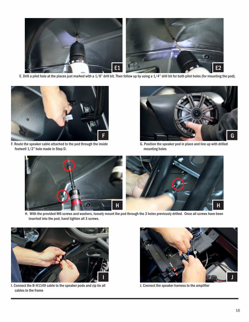
E. Drill a pilot hole at the places just marked with a 1/8” drill bit. Then follow up by using a 1/4” drill bit for both pilot holes (for mounting the pod).
E2E1
G. Position the speaker pod in place and line up with drilled mounting holes
G
H
F. Route the speaker cable attached to the pod through the inside footwell 1/2” hole made in Step D.
I. Connect the B-H1149 cable to the speaker pods and zip tie all cables to the frame
J. Connect the speaker harness to the amplifi er
H. With the provided M6 screws and washers, loosely mount the pod through the 3 holes previously drilled. Once all screws have been inserted into the pod, hand tighten all 3 screws.
F
H
I J
17
RZ3-F652017 Polaris RZR Kick Pod, Cut Template Driver Outside Template
Cut along parimeter
Drill Point
Drill Point

18
19
RZ3-F65
2017 Polaris RZR
Kick Pod, Cut Tem
plate
Cut along parim
eter
Passenger Inside Template
Drill Point
Drill Point

20
21
RZ3-F652017 Polaris RZR Kick Pod, Cut Template
Passenger Outside Template
Cut along parimeter
Drill Point
Drill Point

22
23
RZ3-F65
2017 Polaris RZR
Kick Pod, Cut Tem
plate D
river Inside TemplateC
ut along parimeter
Drill Point
Drill Point

24
25
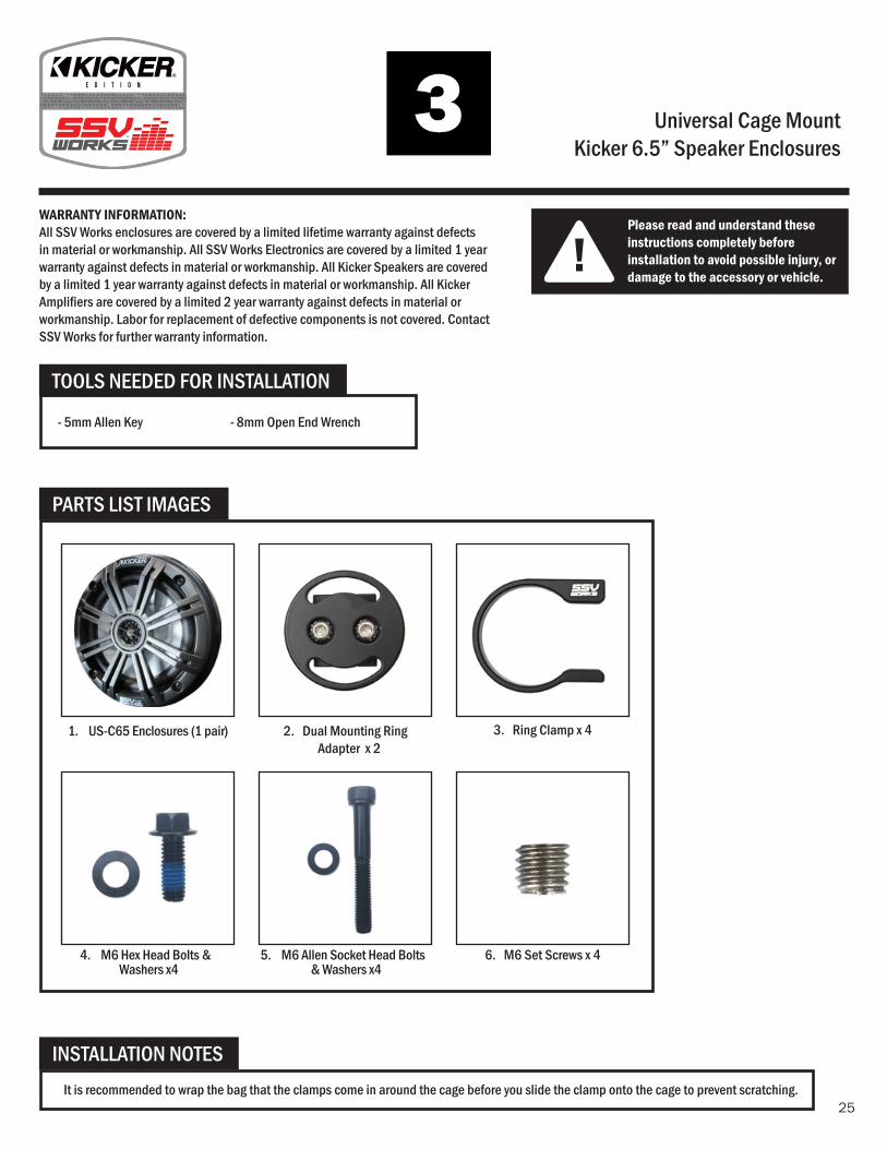
Universal Cage MountKicker 6.5” Speaker Enclosures
!Please read and understand these instructions completely before installation to avoid possible injury, or damage to the accessory or vehicle.
WARRANTY INFORMATION:All SSV Works enclosures are covered by a limited lifetime warranty against defects in material or workmanship. All SSV Works Electronics are covered by a limited 1 year warranty against defects in material or workmanship. All Kicker Speakers are covered by a limited 1 year warranty against defects in material or workmanship. All Kicker Amplifi ers are covered by a limited 2 year warranty against defects in material or workmanship. Labor for replacement of defective components is not covered. Contact SSV Works for further warranty information.
INSTALLATION NOTESIt is recommended to wrap the bag that the clamps come in around the cage before you slide the clamp onto the cage to prevent scratching.
TOOLS NEEDED FOR INSTALLATION
PARTS LIST IMAGES
1. US-C65 Enclosures (1 pair)
4. M6 Hex Head Bolts & Washers x4
5. M6 Allen Socket Head Bolts & Washers x4
3. Ring Clamp x 4
6. M6 Set Screws x 4
2. Dual Mounting Ring Adapter x 2
- 5mm Allen Key - 8mm Open End Wrench
26
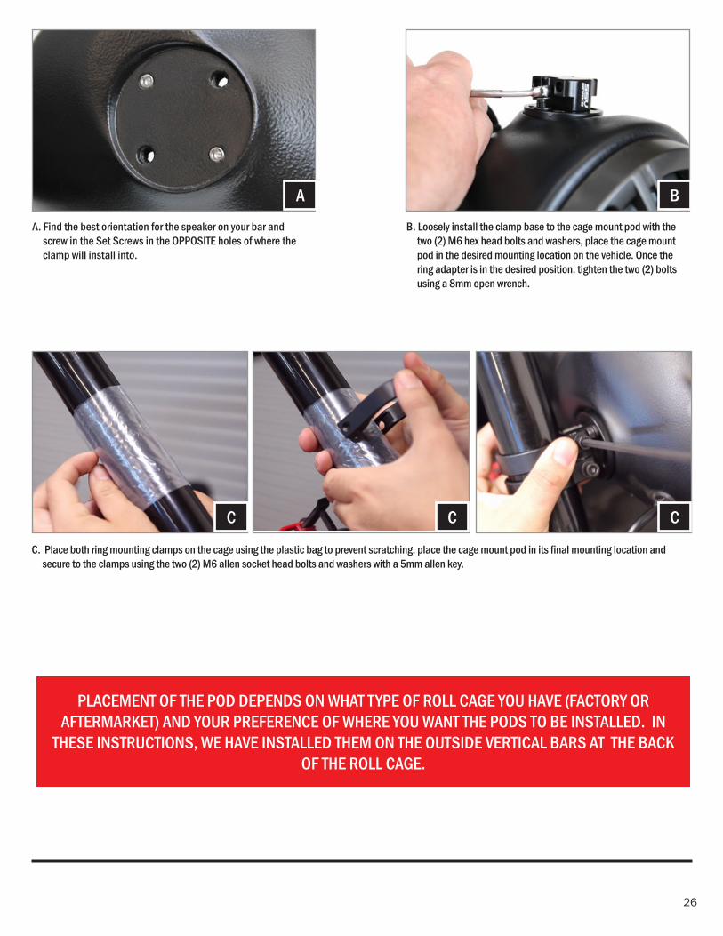
PLACEMENT OF THE POD DEPENDS ON WHAT TYPE OF ROLL CAGE YOU HAVE (FACTORY OR AFTERMARKET) AND YOUR PREFERENCE OF WHERE YOU WANT THE PODS TO BE INSTALLED. IN
THESE INSTRUCTIONS, WE HAVE INSTALLED THEM ON THE OUTSIDE VERTICAL BARS AT THE BACK OF THE ROLL CAGE.
A. Find the best orientation for the speaker on your bar and screw in the Set Screws in the OPPOSITE holes of where the clamp will install into.
B. Loosely install the clamp base to the cage mount pod with the two (2) M6 hex head bolts and washers, place the cage mount pod in the desired mounting location on the vehicle. Once the ring adapter is in the desired position, tighten the two (2) bolts using a 8mm open wrench.
A B
C. Place both ring mounting clamps on the cage using the plastic bag to prevent scratching, place the cage mount pod in its fi nal mounting location and secure to the clamps using the two (2) M6 allen socket head bolts and washers with a 5mm allen key.
C C C
27
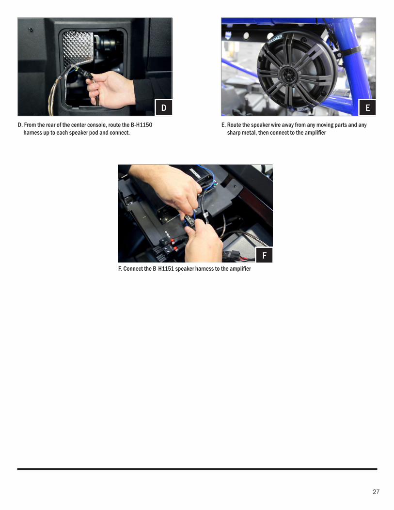
E. Route the speaker wire away from any moving parts and any sharp metal, then connect to the amplifi er
D. From the rear of the center console, route the B-H1150 harness up to each speaker pod and connect.
ED
F. Connect the B-H1151 speaker harness to the amplifi er
F

28
29
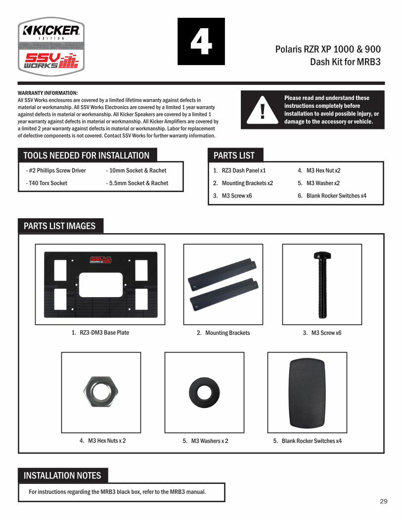
Polaris RZR XP 1000 & 900Dash Kit for MRB3
!Please read and understand these instructions completely before installation to avoid possible injury, or damage to the accessory or vehicle.
WARRANTY INFORMATION:All SSV Works enclosures are covered by a limited lifetime warranty against defects in material or workmanship. All SSV Works Electronics are covered by a limited 1 year warranty against defects in material or workmanship. All Kicker Speakers are covered by a limited 1 year warranty against defects in material or workmanship. All Kicker Amplifi ers are covered by a limited 2 year warranty against defects in material or workmanship. Labor for replacement of defective components is not covered. Contact SSV Works for further warranty information.
1. RZ3 Dash Panel x1
2. Mounting Brackets x2
3. M3 Screw x6
TOOLS NEEDED FOR INSTALLATION PARTS LIST
PARTS LIST IMAGES
4. M3 Hex Nut x2
5. M3 Washer x2
6. Blank Rocker Switches x4
2. Mounting Brackets 3. M3 Screw x61. RZ3-DM3 Base Plate
- #2 Phillips Screw Driver
- T40 Torx Socket
- 10mm Socket & Rachet
- 5.5mm Socket & Rachet
INSTALLATION NOTESFor instructions regarding the MRB3 black box, refer to the MRB3 manual.
5. Blank Rocker Switches x44. M3 Hex Nuts x 2 5. M3 Washers x 2
30
A
B
A
B
A
B
C
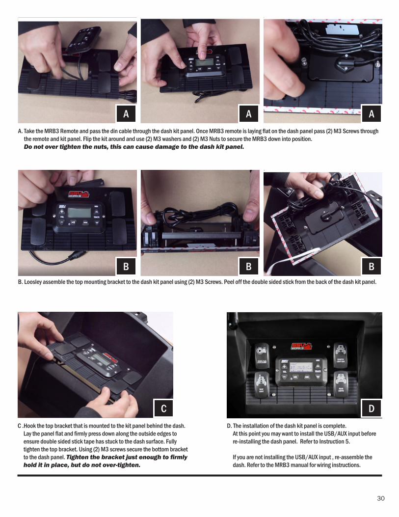
B. Loosley assemble the top mounting bracket to the dash kit panel using (2) M3 Screws. Peel off the double sided stick from the back of the dash kit panel.
C .Hook the top bracket that is mounted to the kit panel behind the dash. Lay the panel fl at and fi rmly press down along the outside edges to ensure double sided stick tape has stuck to the dash surface. Fully tighten the top bracket. Using (2) M3 screws secure the bottom bracket to the dash panel. Tighten the bracket just enough to fi rmly hold it in place, but do not over-tighten.
A. Take the MRB3 Remote and pass the din cable through the dash kit panel. Once MRB3 remote is laying fl at on the dash panel pass (2) M3 Screws through the remote and kit panel. Flip the kit around and use (2) M3 washers and (2) M3 Nuts to secure the MRB3 down into position. Do not over tighten the nuts, this can cause damage to the dash kit panel.
DD. The installation of the dash kit panel is complete.
At this point you may want to install the USB/AUX input before re-installing the dash panel. Refer to Instruction 5.
If you are not installing the USB/AUX input , re-assemble the dash. Refer to the MRB3 manual for wiring instructions.
31
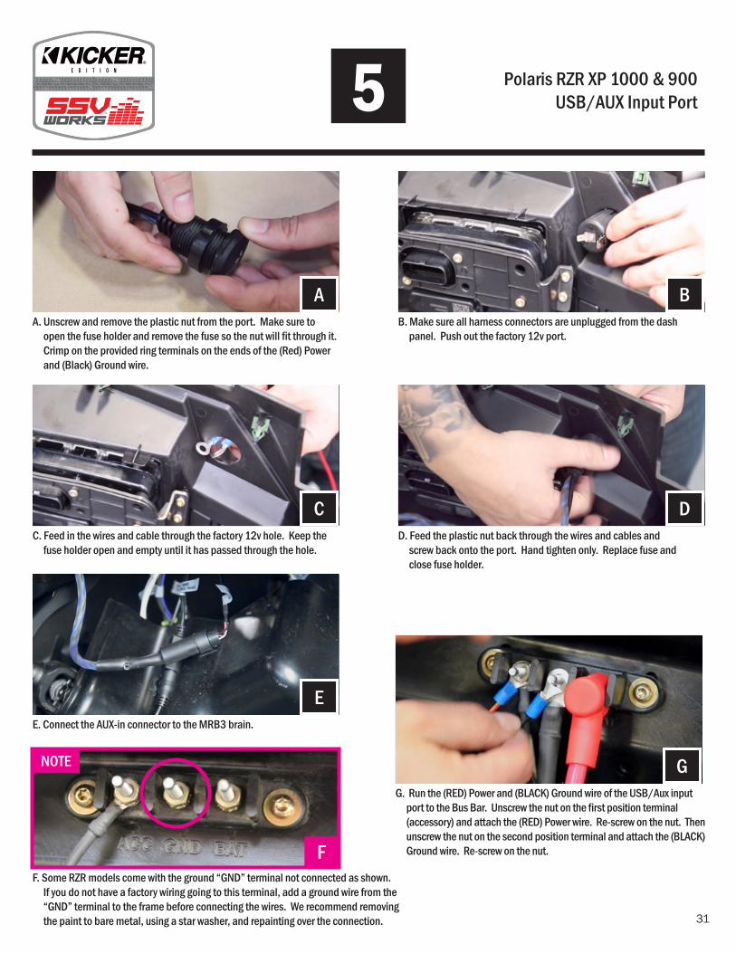
Polaris RZR XP 1000 & 900USB/AUX Input Port
A
C
E
F
NOTE G
B
D
A. Unscrew and remove the plastic nut from the port. Make sure to open the fuse holder and remove the fuse so the nut will fi t through it. Crimp on the provided ring terminals on the ends of the (Red) Power and (Black) Ground wire.
C. Feed in the wires and cable through the factory 12v hole. Keep the fuse holder open and empty until it has passed through the hole.
E. Connect the AUX-in connector to the MRB3 brain.
F. Some RZR models come with the ground “GND” terminal not connected as shown. If you do not have a factory wiring going to this terminal, add a ground wire from the “GND” terminal to the frame before connecting the wires. We recommend removing the paint to bare metal, using a star washer, and repainting over the connection.
G. Run the (RED) Power and (BLACK) Ground wire of the USB/Aux input port to the Bus Bar. Unscrew the nut on the fi rst position terminal (accessory) and attach the (RED) Power wire. Re-screw on the nut. Then unscrew the nut on the second position terminal and attach the (BLACK) Ground wire. Re-screw on the nut.
B. Make sure all harness connectors are unplugged from the dash panel. Push out the factory 12v port.
D. Feed the plastic nut back through the wires and cables and screw back onto the port. Hand tighten only. Replace fuse and close fuse holder.
5
32
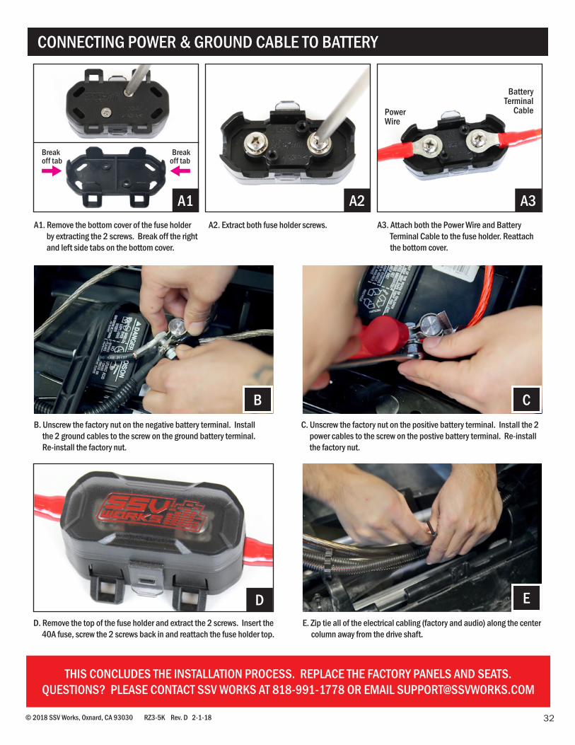
CONNECTING POWER & GROUND CABLE TO BATTERY
© 2018 SSV Works, Oxnard, CA 93030 RZ3-5K Rev. D 2-1-18
CB
A2 A3
ED
B. Unscrew the factory nut on the negative battery terminal. Install the 2 ground cables to the screw on the ground battery terminal. Re-install the factory nut.
A1. Remove the bottom cover of the fuse holder by extracting the 2 screws. Break off the right and left side tabs on the bottom cover.
A2. Extract both fuse holder screws. A3. Attach both the Power Wire and Battery Terminal Cable to the fuse holder. Reattach the bottom cover.
E. Zip tie all of the electrical cabling (factory and audio) along the center column away from the drive shaft.
D. Remove the top of the fuse holder and extract the 2 screws. Insert the 40A fuse, screw the 2 screws back in and reattach the fuse holder top.
C. Unscrew the factory nut on the positive battery terminal. Install the 2 power cables to the screw on the postive battery terminal. Re-install the factory nut.
Power Wire
Battery Terminal
Cable
A1
Break off tab
Break off tab
THIS CONCLUDES THE INSTALLATION PROCESS. REPLACE THE FACTORY PANELS AND SEATS.QUESTIONS? PLEASE CONTACT SSV WORKS AT 818-991-1778 OR EMAIL [email protected]