ruthenium-catalyzed formylations using
TRANSCRIPT
Research Collection
Doctoral Thesis
Ruthenium-catalyzed formylations using carbon dioxide ascarbon source ans solvent
Author(s): Rohr, Markus
Publication Date: 2005
Permanent Link: https://doi.org/10.3929/ethz-a-005114149
Rights / License: In Copyright - Non-Commercial Use Permitted
This page was generated automatically upon download from the ETH Zurich Research Collection. For moreinformation please consult the Terms of use.
ETH Library

Diss. ETH No. 16281
Ruthenium-catalyzed Formylations Using
Carbon Dioxide as Carbon Source
and Solvent
A dissertation submitted to the
Swiss Federal Institute of Technology Zurich (ETH)
for the degree of Doctor of Technical Sciences
presented by
Markus Rohr
Dipl. Chem.-Ing. ETH
born April 10, 1972
citizen of Hunzenschwil (AG)
accepted on the recommendation of
Prof. Dr. A. Baiker, examiner
Prof. Dr. G. Consiglio, co-examiner
2005


Dedicated to myparents
Myrtaf and Fritz Rohr-Deubelbeiss
for all the love, trust, and support

Acknowledgments
Firstly, I would like to express my sincere gratitude to Prof. Dr. A. Baiker
for his support, both personally and professionally, and the opportunity to
complete my doctoral studies in his group.
Moreover, I would like to thank Prof. Dr. G. Consiglio for accepting the
task of co-examiner for this thesis.
A special thank is due to Dr. J.-D. Grunwaldt for his support and
contributions to this thesis. I really appreciated the assistance, scientific
discussions and efforts during the last years.
Furthermore, I would like to thank Dr. C. Beck and W. Kunz for their
valuable help and the many scientific and non-scientific discussions, and
M. Günther for his contributions to this work during his diploma work.
Thanks are also due to my office-mates M. Ramin, Dr. M. Burgener,
M. Caravati, S. Diezi, F. Jutz, and N. van Vegten for sharing a lot of good
times and unforgettable moments, and to the entire Baiker group for their
company and support.
I thank U. Krebs, M. Kupfer, R. Mäder, and P. Trüssel for their help with
fine mechanics and M. Wohlwend for electronic support.
Thanks are due to HASYLAB, DESY in Hamburg, Germany for providing
beamtime and to the lab's beamline staff, M. Herrmann and J. Wienold, for
their support, and also to H. Emerich and W. van Beek of the Swiss-
Norwegian Beamline at ESRF, Grenoble, France for offering beamtime and
for support during the measurements. The Bundesamt für Energie is to be
thanked for its financial support.
Finally, I would like to thank my family and my friends for their love and
support throughout all these years of my education.


Table of Contents
Acknowledgments v
Table of Contents ix
Summary xv
Zusammenfassung xix
1 Introduction 1
1.1 General Aspects of Carbon Dioxide Utilization 1
1.2 Physical and Chemical Properties of Carbon Dioxide 2
1.3 Carbon Dioxide as a Ci-Building Block 4
1.3.1 Synthesis Using Carbon Dioxide 4
1.3.2 Formic Acid and its Derivatives 7
1.3.3 Further Reactions Using Carbon Dioxide as
Ci-Building Block 9
1.4 Carbon Dioxide as a Solvent 12
1.5 Scope of the Thesis 14
1.6 References 16
2 Experimental 27
2.1 Experimental Equipment 27
2.1.1 High-pressure Batch Reactor Cell 27

X
2.1.2 Apparatus for Synthesis of Catalysts in the
Presence of UV-Light 29
2.1.3 View-cell for Phase Behavior Studies 30
2.2 Characterization Methods 30
2.2.1 X-ray Absorption Spectroscopy Cell for Catalyst
Studies in Liquid Phase 31
2.2.2 High-pressure XAS Cell for Studying Simultaneously
the Liquid Phase and the Solid/Liquid Interface 33
2.3 Catalytic Tests 37
2.3.1 Experimental Procedure 37
2.3.2 Analysis 37
2.3.3 Evaluation of Catalytic Tests 38
2.4 References 39
3 Catalyst Characterization under Reaction Conditions
using XANES and EXAFS 41
3.1 Summary 41
3.2 Introduction 42
3.3 Basics of XANES and EXAFS 43
3.4 High-pressure In Situ X-ray Absorption Spectroscopy 47
3.5 Case Study: Ruthenium-catalyzed Formylation of
3-Methoxypropylamine with Hydrogen and
Supercritical Carbon Dioxide 48
3.5.1 Introduction 48
3.5.2 Experimental 49
3.5.3 Results 50
3.5.4 Discussion 52
3.5.5 Conclusions 53

xi
3.6 References 53
4 A Simple Route to Highly Active Ruthenium Catalysts
for Formylation Reactions with Hydrogen and
Carbon Dioxide 59
4.1 Summary 59
4.2 Introduction 60
4.3 Experimental 61
4.4 Results and Discussion 63
4.5 Conclusions 69
4.6 References 69
5 Formylation with Supercritical Carbon Dioxide over
RU/AI2O3 Modified by Phosphines: Heterogeneous or
Homogeneous Catalysis? 73
5.1 Summary 73
5.2 Introduction 74
5.3 Experimental 75
5.3.1 Catalyst Materials 75
5.3.2 Catalytic Formylation of 3-Methoxypropylamine 76
5.3.3 Characterization ofIn Situ Formed Homogeneous
Complex Using ICP-OES 77
5.3.4 Ex Situ and In Situ X-ray Absorption Spectroscopic
Studies 77
5.4 Results 79
5.4.1 Modification of RU/AI2O3 with dppe and its Performance
in the Formylation of 3-Methoxypropylamine 79
5.4.2 Identification of the Catalytically Active Species 82

Xll
5.4.3 Spectroscopic Study of the In Situ Formation of the
Homogeneous Ruthenium Catalyst 86
5.4.4 Structural Identification of the Homogeneous
Ruthenium Complex 88
5.5 Discussion 94
5.6 Conclusions 98
5.7 References 98
6 Solvent-free Ruthenium-catalyzed Vinyl Carbamate
Synthesis from Phenylacetylene and Diethylamine in
Supercritical Carbon Dioxide 103
6.1 Summary 103
6.2 Introduction 104
6.3 Experimental 105
6.4 Results and Discussion 106
6.5 Conclusions 110
6.6 References 110
7 Evaluation of Strategies for the Immobilization of Bidentate
Ruthenium Phosphine Complexes Used for the Formylation
of Amines in Supercritical Carbon Dioxide 113
7.1 Summary 113
7.2 Introduction 114
7.3 Experimental 116
7.3.1 Preparation of the Covalently Bound RuCl2(bspe)2
Catalyst 116
7.3.2 Preparation of the Adsorbed Catalyst RuCl2(dppe)2 on
Aminopropyl-modified Silica 119
Xlll
7.3.3 Preparation of Further Catalytic Materials, Covalently
Bound RuCl2(bspp)2 and In Situ Generated Catalyst
from "Si"-NH2-RuCl3 and dppe 120
7.3.4 Catalytic Formylation of Amines with Supercritical
Carbon Dioxide 121
7.3.5 Physico-chemical Characterization Using X-ray
Absorption Spectroscopy (XANES, EXAFS) and
Further Characterization Methods (XPS, Nitrogen
Physisorption, NMR, and DRIFTS) 121
7.4 Results 125
7.4.1 Preparation and Characterization of
Heterogeneous Catalysts 125
7.4.2 Catalytic Formylation of Amines Using
Immobilized RuCl2(bspe)2 130
7.4.3 Comparison of the Immobilized Ruthenium
Complex and the Adsorbed Ruthenium Complex 132
7.4.4 Structural Analysis of the Solid Catalysts and
the Soluble Species after Reaction 133
7.5 Discussion 138
7.6 Conclusions 142
7.7 References 143
Final Remarks 147
List of Publications 151
Curriculum Vitae 155


Summary
The use of carbon dioxide as a carbon source and solvent is an attractive
approach to the synthesis of formic acid and its derivatives. For that reason,
this strategy has been used in a number of former and present studies.
Formamides can be synthesized using group (VIII) transition metals as
catalysts for the formylation of amines with carbon dioxide and hydrogen.
Applicable amines range from simple primary and secondary amines
(dimethylamine, diethylamine) to cyclic amines, such as, piperidine,
pyrrolidine, and morpholine. Ruthenium phosphine complexes constitute
efficient catalysts for the formylation of amines. In this reaction, carbon
dioxide acts both as reactant and solvent, resulting in a "solventless"
process.
The main focus of this doctoral thesis was the development of new and
simpler homogeneous and heterogeneous catalysts for formylation
reactions, complemented by spectroscopic investigations under ex situ and
in situ conditions. A very simple catalyst system, not investigated
previously, consists of commercially available RUCI3 in the presence of
l,2-bis(diphenylphosphino)ethane (dppe). Catalytic and spectroscopic
investigations using X-ray absorption near edge structure (XANES) and

XVI
extended X-ray absorption fine structure (EXAFS) spectroscopy revealed
that a RuCl2(PPli3)3-like complex formed in situ.
The in situ formed complex was highly active and exhibited turnover rates
comparable to the stepwise synthesized RuCl2(dppe)2 complex. Both of
these catalysts were more active than a RuCl2(PPli3)3 catalyst.
In our search for a simple heterogeneous catalyst system for the
formylation of amines, we modified a commercial RU/AI2O3 catalyst by
addition of dppe. Although this catalyst afforded high activity, closer
inspection revealed that the catalytically active species was a homogeneous
Ru-complex. This could be confirmed with the help of a novel
spectroscopic in situ batch reactor cell for X-ray absorption spectroscopy.
By investigating both the solid and the liquid phase, it could be proven that
a homogeneous complex formed as soon as dppe was added. The solid
RU/AI2O3 catalyst was reduced as a consequence of the presence of
hydrogen. Further catalytic studies and elemental analysis by ICP-OES
showed that the formed ruthenium complex acts as a homogeneous catalyst
and is present in only small amounts in the reaction mixture (50 -
200 ppm). Its structure could be further elucidated using a specially
designed EXAFS cell with a long path length to record transmission
EXAFS spectra in liquid solution even at very low concentrations. The
structure of the active species was found to be similar to that of a
Ru(dppe)2X2 complex.
In a final step, different immobilization procedures for the presently most
active RuCl2(dppe)2 complex were explored. Coordinatively anchored
complexes on specially modified silica did not prove to be sufficiently
stable, probably because of the harsh reaction conditions and leaching of
the complex. The best results were obtained using covalently immobilized

XV11
ruthenium complexes. This catalyst also deactivated significantly less than
the coordinatively anchored complexes. The deactivation was attributed to
the destruction of the immobilized catalyst, as also evidenced by
spectroscopic studies.
Apart from these new catalyst preparation routes, the formylation of
primary and secondary amines was extended to substrates with other
functional groups, such as additional ether or alcohol groups (3-methoxy-
propylamine, 2-ethylaminoethanol, 2-methylaminoethanol, and morpho¬
line) in order to extend the scope of possible formylation reactions in
supercritical carbon dioxide.
Finally, the synthesis of vinyl carbamate from phenylacetylene,
diethylamine, and carbon dioxide was targeted in our attempts to extend the
scope of reactions which utilize carbon dioxide as a Ci-building block and
as solvent. RuCl2(C5H5N)4 and RuCl2(/76-C6H6)PMe3 catalysts were
found to be suitable for this reaction, making it a "green" alternative to the
synthesis of vinyl carbamates using phosgene.


Zusammenfassung
Die Verwendung von Kohlendioxid als Kohlenstoffbaustein und Lösungs¬
mittel ist ein interessanter Ansatz zur Herstellung von Ameinsensäure und
ihrer Derivate. Im Speziellen können Formamide aus Kohlendioxid und
Wasserstoff durch übergangsmetallkatalysierte Formylierungen an Aminen
synthetisiert werden. Primäre, sekundäre sowie auch zyklische Amine sind
für Formylierungen zugänglich. Beispiele dafür sind Diethylamin, Piperi-
din, Pyrrolidin und Morpholin. Ruthenium-Phosphin-Komplexe zeigen
exzellente katalytische Eigenschaften für die Formylierung in über¬
kritischem Kohlendioxid, das gleichzeitig als Edukt und Lösungsmittel
dient.
Der Fokus in dieser Doktorarbeit wurde auf die Entwicklung neuartiger
und einfacherer homogener sowie heterogener Katalysatoren für
Formylierungen in überkritischem Kohlendioxid gelegt. Informationen
über die lokale Struktur und das Verhalten der Katalysatoren unter
Reaktionsbedingungen wurden mit ex situ und in situ Röntgenabsorptions-
spektroskopie gewonnen.
Ein einfaches - bisher noch nicht betrachtetes - katalytisches System geht
von handelsüblichem RUCI3 und l,2-Bis(diphenylphosphino)ethane (dppe)
aus. Katalytische und spektroskopische Untersuchungen mit Röntgen-

XX
absorptionsspektroskopie (X-ray absorption near edge structure, XANES,
und extended X-ray absorption fine structure, EXAFS) belegten die in situ
Bildung eines hochaktiven Komplexes, dessen Struktur ähnlich derjenigen
von RuCl2(PPh3)3 ist.
Auf der Suche nach einem einfachen heterogenen Katalysatorsystem für
Formylierungen von Aminen wurde ein kommerziell erhältlicher RU/AI2O3
Katalysator durch Zugabe von dppe modifiziert. Röntgenabsorptions-
spektroskopische Untersuchungen zeigten die Bildung homogener
Ruthenium-Komplexe sofort nach Zugabe von dppe. Dazu wurde eine
Batch-Reaktorzelle konstruiert, die gleichzeitige in situ Messungen an der
festen (Katalysator) und an der flüssigen Phase (Reaktionsmischung)
ermöglichte. Der anwesende Wasserstoff reduzierte dabei den an der Luft
teilweise oxidierten RU/AI2O3 Katalysator. Weitere katalytische Studien
und Elementaranalysen mittels ICP-OES zeigten, dass der gebildete
Ruthenium-Komplex als homogener Katalysator vorliegt und in der
Reaktionsmischung nur in sehr kleinen Mengen vorhanden ist (50-
200 ppm). Um die Strukturaufklärung bei diesen kleinen Konzentrationen
zu ermöglichen, wurde eine EXAFS-Flüssigkeitszelle mit grösserer
Weglänge für die Röntgenstrahlen entworfen. Mit EXAFS Messungen in
Transmissionsgeometrie wurden Spektren der katalytisch aktiven Spezies
in der flüssigen Phase erhalten. Die Analyse der Spektren zeigte, dass die
Struktur dieser Partikel einem Ru(dppe)2X2-Komplex gleicht.
Verschiedene Immobilisierungsverfahren wurden für die hochaktiven
RuCl2(dppe)2-Komplexe entwickelt und verglichen. Auf Amin-
modifiziertem Silika koordinativ am Zentralatom gebundene Komplexe
zeigten keine ausreichende Stabilität. Die besten Resultate wurden mit
kovalent immobilisierten Ruthenium-Komplexen erreicht. Diese

XXI
Katalysatoren zeigten eine wesentlich geringere Desaktivierung als die
koordinativ verankerten Komplexe.
Abgesehen von diesen neuen Varianten der Katalysatorherstellung wurde
die Palette möglicher Formylierungen durch Amine mit zusätzlichen
funktionellen Gruppen erweitert. Amine mit Ether- oder Alkoholgruppen,
wie 3-Methoxypropylamin, 2-Ethylaminoethanol, 2-Methylaminoethanol
und Morpholin wurden erfolgreich zu den entsprechenden Formamiden
umgesetzt.
Als weitere Reaktion, die ebenfalls Kohlendioxid als Ci-Baustein und
Lösungsmittel verwendet, wurde die Synthese von Vinylcarbamat aus
Phenylacetylen, Diethylamin und überkritischem Kohlendioxid untersucht.
RuCl2(C5H5N)4 and RuCl2(/76-C6H6)PMe3 waren in dieser Reaktion
katalytisch aktiv, die eine „grüne" Alternative zur Synthese von Vinyl¬
carbamat aus Phosgen darstellt.


Chapter
Introduction
1.1 General Aspects of Carbon Dioxide Utilization
The large amount of carbon dioxide released into the atmosphere every
year has been the topic of countless heated discussions about the role this
greenhouse gas plays on the future state of the climate. In energy
production, carbon dioxide is emitted by combustion processes, based on
fossil raw materials, such as crude oil, natural gas, and coal. Other sources
are, for example, chemical processes (e.g. hydrogen production) and the
cement industry.
The concentration of carbon dioxide in the atmosphere has increased in the
last 200 years from 250 ppm to 360 ppm [1], mostly due to the growing
demand for energy and to the industrial production of chemicals and
pharmaceuticals. As a consequence, the natural CO2 equilibrium is
expected to become noticeably unbalanced by human industrial activities.
In nature, the CO2 equilibrium is maintained by a closed loop involving the
fixation of atmospheric carbon dioxide in organic material by the
photosynthesis process, the refeeding by animal respiration, and the
degradation of organic material. In the photosynthesis process, one of the
most important chemical processes on earth, CO2 and water are converted
to glucose and oxygen with the effect of sunlight.
1

2 Chapter 1
Strategies to avoid further increases of CO2 emission, and to extend the
availability of the non-renewable fossil raw material sources are of
tremendous importance to the development of earth's climate and, with it,
the future of mankind. Promising ways to implement such strategies exist,
including energy saving measures, increasing efficiency in energy
production, optimizing consumption processes, and increasingly making
use of non-fossil renewable energy sources.
Another attractive strategy is the use of carbon dioxide as a source of
carbon for chemical synthesis. The abundance of carbon dioxide released
by the processes described above constitutes a source of cheap and easily
available Ci-building blocks. Carbon dioxide is non-toxic and has the
capability to replace other toxic Ci -building blocks, such as carbon
monoxide and phosgene [2-5].
In addition, the excellent properties of supercritical carbon dioxide with
regard to miscibility, diffusion, and mass transfer coefficients make it a
preferred solvent in chemical processes, at the same time offering a
replacement for environmentally hazardous organic solvents [6-8].
1.2 Physical and Chemical Properties of Carbon Dioxide
Carbon dioxide is a non-flammable, non-toxic, colorless, and odorless gas,
which is highly abundant and renewable at low costs [8, 9]. Carbon dioxide
exhibits its supercritical point at relatively mild conditions, one of the most
important advantages of using carbon dioxide in chemical reactions as
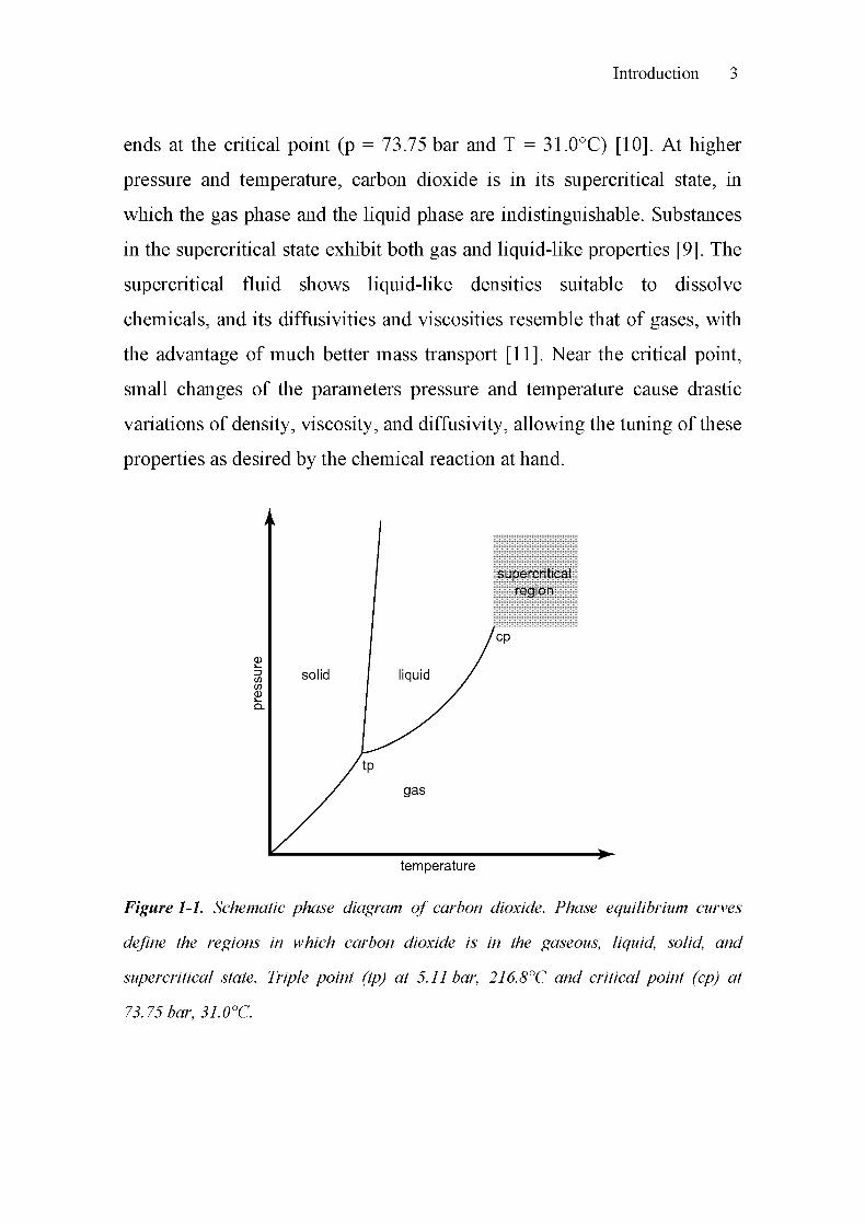
solvent. Figure 1-1 shows a schematic phase diagram of carbon dioxide.
The solid, liquid and gaseous states of CO2 are separated by the
corresponding phase equilibrium curves. The liquid-gas vapor pressure
curve, for example, starts at the triple point (p = 5.11 bar, T = 216.8°C) and
Introduction 3
ends at the critical point (p = 73.75 bar and T = 31.0°C) [10]. At higher
pressure and temperature, carbon dioxide is in its supercritical state, in
which the gas phase and the liquid phase are indistinguishable. Substances
in the supercritical state exhibit both gas and liquid-like properties [9]. The
supercritical fluid shows liquid-like densities suitable to dissolve
chemicals, and its diffusivities and viscosities resemble that of gases, with
the advantage of much better mass transport [11]. Near the critical point,
small changes of the parameters pressure and temperature cause drastic
variations of density, viscosity, and diffusivity, allowing the tuning of these
properties as desired by the chemical reaction at hand.
supercriticalregion
temperature
Figure 1-1. Schematic phase diagram of carbon dioxide. Phase equilibrium curves
define the regions in which carbon dioxide is in the gaseous, liquid, solid, and
supercritical state. Triple point (tp) at 5.11 bar, 216.8°C and critical point (cp) at
73.75 bar, 31.0°C.

4 Chapter 1
With these properties, supercritical fluids constitute an attractive replace¬
ment for conventional and maybe even toxic industrial solvents [12-14].
The solvent can be easily separated from the products after reaction by
decreasing the pressure, eliminating the need for expensive separation
procedures. The decaffeination of coffee with supercritical carbon dioxide,
the replacement of perchloroethylene, or the applications in semiconductor
processing [14-16] illustrate only some of the many industrial uses of
supercritical fluids [9, 17]. The use of supercritical fluids in industry is not
restricted to extractions, as indicated by a growing interest in the fields of
polymerization reactions [18], catalysis [6, 19], and material science [20].
1.3 Carbon Dioxide as a Ci-Building Block
1.3.1 Synthesis Using Carbon Dioxide
Carbon dioxide is not only an interesting solvent, it has also been used as a
reactant. One of the first, simple processes using CO2 as a reactant was the
Solvay process for the production of sodium carbonate, the basis of the
glass and ceramic industry. In this process, carbon dioxide and ammonia
are fed into a saturated solution of sodium chloride. The precipitated
sodium bicarbonate is calcinated and sodium carbonate is produced as
depicted in Scheme 1-1.
2 NaCI + 2 C02 + 2 NH3 + 2 H20 2 NaHCQ3 + 2 NH4CI
2NH4CI + CaO - 2 NH3 + CaCL, + H20
2 NaHCO^ Na2C03 + H20 + C02
Scheme 1-1. Solvay process for the production of sodium carbonate from carbon
dioxide, developed 1865 by Ernest Solvay.
Introduction 5
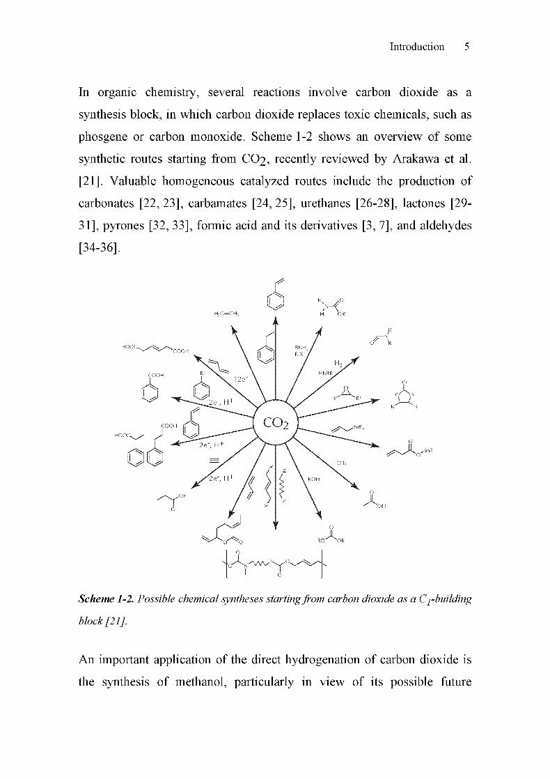
In organic chemistry, several reactions involve carbon dioxide as a
synthesis block, in which carbon dioxide replaces toxic chemicals, such as
phosgene or carbon monoxide. Scheme 1-2 shows an overview of some
synthetic routes starting from CO2, recently reviewed by Arakawa et al.
[21]. Valuable homogeneous catalyzed routes include the production of
carbonates [22, 23], carbamates [24, 25], urethanes [26-28], lactones [29-
31], pyrones [32, 33], formic acid and its derivatives [3, 7], and aldehydes
[34-36].
H
<OR
R
O R
A.o o
R-^R
f^' ^CT
Scheme 1-2. Possible chemical syntheses startingfrom carbon dioxide as a Ci-building
block [21].
An important application of the direct hydrogénation of carbon dioxide is
the synthesis of methanol, particularly in view of its possible future

6 Chapter 1
application in the area of hydrogen storage. Industrial production of
methanol is based on synthesis gas CO/H2, with either Zn/Q-203 acting as
catalyst in the high-pressure process (400°C / 200 bar), or Cu/Zn/Al acting
as catalyst in the ICI process (250°C / 50 bar) [37], as depicted in
Scheme 1-3. In both cases, carbon dioxide is added [38,39]. The direct
synthesis of methanol from CO2 instead of synthesis gas, as well as
efficient heterogeneous catalysts, such as Cu/ZrC>2, Cu/SiC>2, Cu/ZnO, and
Q1/AI2O3, has been reported as well (see [40-42]).
1) CO + 2H2 « CH3OH
2) C02 + 3H2 « CH3OH + H20
3) CO + H20 » C02 + H2
Scheme 1-3. Industrial synthesis of methanol 1) starting from synthesis gas or
2) directly from carbon dioxide. 3) CO2 can be producedfrom CO by way of the water
gas shift reaction.
The production of aspirin is an excellent example of an organic reaction
using CO2 as a building block. The synthesis of the intermediate salicylic
acid is achieved industrially by the Kolbe-Schmitt process, carboxylating
sodium phenolate with carbon dioxide [43], as illustrated in Scheme 1-4.
co, +
H+rrc^^XOONa ~-^ "COOH
Ur
Scheme 1-4. Production ofsalicylic acid by the "Kolbe-Schmitt" reaction.
Carbon dioxide is rather inert and difficult to activate, probably the main
reason why toxic carbon monoxide is still the favored Ci -synthesis block in
industrial processes [5,44,45]. However, in certain cases catalysts allow

Introduction 7
the use of carbon dioxide in the production of chemicals, such as urea and
its derivatives [45-47], organic carbonates [45,48-51], and salicylic acid
[45].
For the catalytic activation of carbon dioxide, the use of the supercritical
state of CO2 offers some advantages [5, 44, 52]. In addition to the liquid¬
like density, high diffusivity, and high mass transfer coefficients as
discussed in section 1.2, it has the desirable property that no additional
organic solvent is needed for the reaction. Two different strategies exist to
activate the relatively inactive carbon dioxide: 1) the use of highly reactive
reactants, e.g. epoxides forming organic carbonates, and 2) the use of
another "oxygen sink", e.g. water, since, from a thermodynamic point of
view, CO2 is an oxygen sink by itself. In the latter case, the reaction of
carbon dioxide with alcohols or amines in the presence of hydrogen leads
to formic acid derivatives, which is particularly interesting in connection
with solar or hydrothermal hydrogen production [53].
1.3.2 Formic Acid and its Derivatives
Formic acid is used in the silage of animal feed, for tanning and dyeing in
the textile industry, as a detergent, and as an intermediate in chemical
synthesis of pharmaceuticals, synthetic sweetening, and pesticide
production. The annual industrial production of 300 000 t of formic acid is
based on the hydrolysis of methyl formate that is formed from methanol
and carbon monoxide in the presence of sodium methoxide as catalyst. The
resulting by-product methanol is recycled.
An important alternative route to formic acid and its derivatives is the
transition-metal-catalyzed hydrogénation of carbon dioxide [54-60].

8 Chapter 1
Addition of a base stabilizes the metastable formic acid and lowers the
reaction enthalpy, thus thermodynamically favoring the products [4].
Ruthenium complexes with phosphine ligands show excellent activities in
the formation of formic acid, especially RuCl2(P(CH3)3)4 [61]. The
authors applied the system to the production of alkylformamides by adding
a primary or secondary amine like dimethylamine, diethylamine,
propylamine [61-63]. The proposed mechanism then proceeds via the
formation of the dialkylammonium dialkylcarbamate, as shown in
Scheme 1-5.
2 C02 + 2 H2 * 2 HCOOH
HNR2 + C02 .« R2NCOOH
R2NCOOH + HNR2 « [H2NR2][02CNR2]
2 HCOOH + [H2NR2][02CNRJ 2 R2NCHO + 2 H20 + C02
C02 + H2 + HNR2 R2NCHO + HzO
Scheme 1-5. Proposed reactions involved in the synthesis offormamides with amine,
hydrogen, and carbon dioxide.
Up to now, different homogeneous catalysts have been used in the
formylation of primary and secondary amines. High conversion with a
selectivity of 100% could be achieved with RuH2(P(CH3)3)4,
RuCl2(P(CH3)3)4, RuH2(P(C6H5)3)4, and RuCl(02CCH3)(P(CH3)3)4
[60,61,64], or with in situ formed complexes starting from
[RuCl2(C6H6)]2, RuCl2(DMSO)4, and [RuCl2(COD)]n [65]. Using
catalysts like RuCl2(PPh3)3, Ru3(CO)i2, and RuCl2(dppe)2 [62, 63], the
suitability of functionalized amines, such as pyrrolidine, piperidine,
piperazine, aniline, morpholine, and a-methylbenzylamine [66], for
carbamate
formation

Introduction 9
formylation reactions have been demonstrated. It could be further shown
that bidentate ruthenium phosphine catalysts of the type RUCI2L2 (L =
dppm, dppe, dppp) achieved the highest conversion and selectivity in the
formylation of amines with supercritical carbon dioxide and hydrogen [62,
66,67].
The development of heterogeneous catalysts for the formylation in
supercritical carbon dioxide is an attractive strategy with regard to
continuous processes. In particular, hybrid catalysts allow combining the
advantages of heterogeneous catalysts (stability, separation, and reuse) with
the excellent catalytic behavior of the homogeneous analogs.
Heterogeneous catalysts were investigated by Kröcher et al. [68-70],
incorporating Ru, Ir, Rh, Pt, and Pd complexes into silica gels. Hybrid
catalysts containing bidentate ruthenium phosphine complexes turned out
to give best performance [71], even higher than the most active
homogeneous catalysts previously known [60, 72].
1.3.3 Further Reactions Using Carbon Dioxide as Ci-Building Block
There exist several additional synthetic routes using carbon dioxide as
reactant, as summarized in Table 1-1. The synthesis of dimethyl carbonate
from CO2 and methanol, the synthesis of cyclic carbonates, and the
hydroformylation of alkenes are particularly interesting and will therefore
be discussed in more detail in this section.
Toxic and corrosive methylating or carbonylating agents like phosgene and
dimethyl sulfate may be replaced by the non-toxic dimethyl carbonate
which can be synthesized from carbon dioxide and methanol [73, 74], as
depicted in Scheme 1-6. Organotin compounds, Sn(IV) and Ti(IV)
alkoxides, and metal acetates were used as catalysts [75-77]. Note that in

10 Chapter 1
these cases the product yield is limited by the reaction equilibrium to less
than 5%. For high selectivity, weak Broensted acidity and base functions
are required, which may be satisfied, for example, by bifunctional catalysts
like ZrC>2, ZrC>2 in combination with H3PO4, CeC>2, and Ce02-Zr02-
Table 1-1. Heterogeneous catalyzed reactions using carbon dioxide both as Ci-building
block and as solvent in the supercriticalfluid region.
Product Reactant Catalyst Solvent p/bar T/°C Refs.
Dimethyl
carbonate
MethanolCe02-Zr02
Pd/ß-Ga203C02
60-210
10
70-170
50-450
[74]
[78]
Propylene
carbonate
Propylene
oxide
Mg-Al-0
different zeolities
co2/
DMF
50-140 150-200 [79-83]
Propylene
carbonate
Propylene
oxide
ZnBr2(Py)2
immobilizedC02 40-50 100-140 [84]
Cyclic
carbonateEpoxide ZnBr2(Poly-Py)2 C02 35 100 [85]
Styrene
carbonateEpoxide
Mg-based and
uncatalyzedC02 20-80 100-150 [79]
Dimethyl Epoxides
carbonate and KI/ZnO C02 165 150 [86]
and glycols methanol
Dimethyl
carbonatesGlycols
Mg-based
smectite catalystsC02 80 150
[87]
[88]
Aldehydes,
alcohols
Alkenes Ru complexesC02/co-
solvent
60-80 140-160 [89-91]
Aldehydes,
alcohols
Alkenes Rh complexesC02/
toluene
184 175 [92]

Introduction 11
2 CH3OH + C02 (CH30)2CO + H20
Scheme 1-6. Schematic illustration of the synthesis ofdimethyl carbonatesfrom carbon
dioxide and methanol.
Starting with carbon dioxide, cyclic carbonates can be synthesized from
epoxides [93], using Lewis acids, transition metal or organometallic
complexes, and polysiloxane-supported metal halides under high-pressure
conditions [94, 95], as illustrated in Scheme 1-7. High yields were obtained
with alkali metal salts in the presence of phase transfer agents such as
crown ethers or quarternary ammonium salts [96]. A new catalytic system,
based on organotin halides with quaternary ammonium or phosphonium
salts, was found by Baba et al. [97]. It delivers high yields under high-
pressure conditions (p = 50 bar, T = 40°C). Insoluble polystyrene beads
containing quaternary ammonium or phosphonium salts [98], polymer-
supported quaternary onium salts [98], immobilized cobalt complexes on
silica [99], and polymer-supported zinc complexes [85], act as
heterogenized catalytic systems, but show significant lower yields than the
homogeneous catalyzed reactions.
o
A
Scheme 1-7. Synthesis of propylene carbonate from propylene epoxide and carbon
dioxide.
The cycloaddition of CO2 to propylene oxide [84] may serve as an
example of the cyclic carbonate production. Its result is propylene

12 Chapter 1
carbonate, an intermediate for polycarbonates or other polymers, which is
also used as an aprotic solvent in the production of lithium batteries,
polyurethanes, and cosmetics [93].
Hydroformylation of alkenes is an important commercial route to
aldehydes and alcohols, the production currently exceeding six million tons
per year [100]. Classically, the synthesis is based on carbon monoxide and
alkenes as reactants, catalyzed by homogeneous transition metal
complexes. Tominaga et al. [89,90] found, that ruthenium carbonyl
clusters and alkaline metal halides catalyze the hydroformylation of alkenes
with carbon dioxide. In a multi-step process, the CO2 is probably first
reduced to CO and used in situ for the hydroformylation of alkenes with
catalysts such as H4Ru4(CO)i2, Ru3(CO)i2, and [Ru(CO)3Cl2]2 [91, 92].
The ratio of the products, aldehydes, alcohols, and alkanes, strongly
depends on the reaction conditions. Note that in all these reactions
homogeneous catalysts were applied predominantely.
1.4 Carbon Dioxide as a Solvent
The fact that carbon dioxide is rather inert is an advantage even when only
used as a solvent. In addition, the physical properties are quite favorable,
see chapter 1, section 1.2. The adjustability of the diffusion rate, mass and
heat transfer - in contrast to liquids - is desirable in heterogeneous cataly¬
sis, since mass transfer by diffusion often turns out to be a limiting step.
The tunability of the solvent properties by varying pressure and co-
solvents, and the elimination of gas/liquid and liquid/liquid mass transfer
resistances, are important features of the solvent. Heterogeneously
catalyzed reactions in supercritical fluids thus promise improvements in
terms of the reaction rate, control of the selectivity, and deactivation of the
Introduction 13
catalyst [101-104]. Compared to other supercritical fluids, such as
ammonia, ethane, ethene, methanol, and water, supercritical carbon dioxide
is often used as solvent, due to its moderate critical pressure of 73.8 bar, its
critical temperature of 31.1°C, its relatively high inertness, and its low
production costs.
Hydrogénation [105-111], partial oxidation [112-118], and isomerization
[119-122] reactions are some of the heterogeneously catalyzed reactions in
supercritical carbon dioxide that have received considerable attention.
Hydrogénation is typically a fast reaction that is diffusion-limited in
conventional solvents because of the low solubility of hydrogen in the
solvents and the mass transport limitations due to the gas/liquid mass
transfer. Interesting areas in the field of heterogeneously catalyzed
hydrogénations in supercritical carbon dioxide are the hydrogénation of
building blocks for fine chemicals and pharmaceuticals [123-127], as well
as the enantioselective hydrogénation on chirally modified surfaces, e.g.
the enantioselective hydrogénation of ethyl pyruvate on Pt/Al203 in the
presence of a cinchona alkaloid [128-130].
Because of the non-flammability, the miscibility, and the chemically inert
behavior, carbon dioxide commends itself as solvent for oxidation reactions
with molecular oxygen [103, 131, 132]. Apart from these properties, the
high diffusion constants of supercritical carbon dioxide were supposed to
improve the desorption of the partial oxidation products, which are strongly
adsorbed on the catalyst surface during reaction [133, 134]. Furthermore,
the higher heat capacity of supercritical carbon dioxide, as compared to
gases, and the higher mass transfer coefficient, as compared to liquid
solvents, is an advantage in these chiefly exothermic oxidations. In the field
of hydrocarbon activation, partial oxidation reactions were performed with

14 Chapter 1
propane [113], propylene [135], or in the epoxidation of olefins [136], for
example. In the area of partial oxidation of alcohols, noble metal catalyzed
oxidations of water-insoluble alcohols to carbonyl compounds [137, 138]
received particular interest.
Finally, preventing catalyst coking by extracting coke precursors in situ due
to its liquid-like densities and enhanced mass transfer properties favor
supercritical CO2 as solvent in isomerizations processes such as 1-hexene
or n-butane isomerizations [139, 140].
1.5 Scope of the Thesis
The aim of this doctoral thesis is to develop new and simpler catalytic
systems in the field of homogeneously and heterogeneously catalyzed
formylation reactions, combined with spectroscopic investigations under ex
situ and in situ conditions. The envisaged strategies are depicted in
Figure 1-2. The catalytic activity of the homogeneous catalysts
RuCl2(dppe)2 and RuC^(dppp)2 (route 1) are well known from earlier
work and are used in this work for comparison. To simplify the synthesis of
active catalysts, the in situ formation of catalysts (route 2) is evaluated. For
this purpose, in situ generated catalysts starting from a simple ruthenium
salt, RUCI3, in the presence of phosphine ligands (PPI13 and dppe) are
tested. Additionally, the in situ modified solid RU/AI2O3 catalyst with dppe
is viewed as a promising approach. On the way towards structurally stable
heterogeneous catalysts, two groups of heterogenized catalysts attract
special interest: adsorbed catalysts (RuCl2(dppe)2/Si02 and "Si"-NH2-
RUCI3 + dppe) in route 3, and hybrid-gel catalysts with covalently
anchored Ru-complexes (RuCl2(bspe)2/Si02 and RuCl2(bspp)2/Si02) in

Introduction 15
route 4. Beside their catalytic performance, the structural stability is of
particular interest.
Homogeneous route
0
In situ route
©
Adsorption route
©
RuCI Ru/Al,0
Ph. Ph.
.P. 2CI PJ I
OK)p p
Ph, Ph,
n+cr
- dppe
cPh, Ph,P. CI Pj
Ph. Ph.
^Pv CI P^\l/ ^1 <\!/>Ru > Ru </IS/1 </i\>P CI P P CI P
Ph, Ph, Ph. Ph.
H„ CO dppe H,, C02
RuCI2(dppe)2 Ru(dppe)2X2
dppe
O I O-Si-0
.s; °s /b\
i /°
o-
O ! O-Si-0' ° /b\
/ ô °--Si-0
\
/°Immobilization route
\/—Si-
JSi-O.
'o-
\l
0'S|-Si-O.
\
Ov I
.Sk0 o
1 I
Sl Si!o
©
.OH HO^ l
Ph PIV\ .Si
;r, ci p ^-^
\
"OI .ov ,
'Si Si.I l
Ox ,0Si
C X )^p ci p^^Ph Pfî"
I „O-Si—.Si, I
0 0 Ll „O-SiSu \
so' "o
ill,
\/ ^o-—Si-O, I
I .sks.
I 0 0
Si-O^ I I „OH
/ .Su „Si.
.SiHO l
O.
-Sl-n'l
/Oo
o' "9„O^ I „O-Si—
? /
oV
o'
-s,."o"
— Si-
-sr
\
o
Si Sll l OH
\ Os „O\ Si
o
HO^ l
Ph PIV\ .Si
P. CI P ^~^
\YRu
/ I \P CI P.Ph Ph" .Si
HO l
O.
I ,0-Si—•Sk I
0 I.
1 .O-Si
..Sk \
o ox
.s',CO' -o
-Si-
/ °-0
,0V I ,0-Si-a /
! %0-S|-^
Figure 1-2. Classification of the catalysts synthesized and investigated in this work.
1) the homogeneous catalysts RuCÏ2(dppe)2 and RuCÏ2(dppp)2, 2) the in situ formed
catalysts from RuCl$ and Ru/A^O^ with dppe, 3) the adsorbed catalysts
RuCl2(dppe)2/Si02 and RuCl^/Si02 with dppe, 4) the immobilized catalysts
RuCl2(bspe)2/Si02andRuCl2(bspp)2/Si02.
In order to gain more insight into the structure of the catalysts under
reaction conditions, and in order to determine whether the reactions are
homogeneously or heterogeneously catalyzed, the catalysts are investigated
in situ and ex situ using XANES and EXAFS. For this purpose, suitable
spectroscopic cells are required.

16 Chapter 1
Finally, the extension of possible substrates as well as the reaction concept
are investigated. The formylation of different amines with additional
functional groups is treated as an important extension to the commonly
investigated scope of substrates.
In addition, the synthesis of vinyl carbamate from phenylacetylene, amines,
and carbon dioxide is studied using different homogeneous ruthenium
catalysts. As before, the aim is to use CO2 both as reactant and as solvent.
1.6 References
[I] A. Behr, Carbon Dioxide Activation by Metal Complexes, VCH,
Weinheim, New York (1988).
[2] A. Behr, Angew. Chem. Int. Ed. Engl. 27 (1988) 661.
[3] W. Leitner, Angew. Chem. Int. Ed. Engl. 34 (1995) 2207.
[4] P. G. Jessop, T. Ikariya, R. Noyori, Chem. Rev. 95 (1995) 259.
[5] A. Baiker, Appl. Organomet. Chem. 14 (2000) 751.
[6] A. Baiker, Chem. Rev. 99 (1999) 453.
[7] P. G. Jessop, T. Ikariya, R. Noyori, Chem. Rev. 99 (1999) 475.
[8] P. G. Jessop, W. Leitner, Chemical Synthesis Using Supercritical
Fluids, Wiley-VCH, Weinheim (1999).
[9] L. T. Taylor, Supercritical Fluid extraction (Techniques in
Analytical Chemistry Series), Wiley, New York (1996).
[10] T. Andrews, Phil. Trans. 159 (1869) 575.
[II] C. A. Eckert, B. L. Knutson, P. G. Debenedetti, Nature 383 (1996)
313.
Introduction 17
12
13
14
15
16
17
18
19
20
J. M. DeSimone, Z. Guan, C. S. Elsbernd, Science 257 (1992) 945.
J. M. DeSimone, E. E. Maury, Y. Z. Menceloglu, J. B. McClain, J.
Romack, J. R. Combes, Science 265 (1994) 356.
D. Bradley, New Scientist 6 (1994) 32.
K. Zosel, Angew. Chem. 90 (1978) 702.
J. W. King, L. L. Williams, Curr. Opin. Sol. State Mat. Sei. 7 (2003)
413.
M. McHugh, V. J. Krukonis, Supercritical Fluid Extraction:
Principles and Practice, Butterworth-Heinemann, Boston (1994).
J. L. Kendall, D. A. Canelas, J. L. Young, J. M. DeSimone, Chem.
Rev. 99 (1999) 543.
J.-D. Grunwaldt, R. Wandeler, A. Baiker, Catal. Rev. - Sei. Eng. 45
(2003)1.
Y.-P. Sun, Supercritical Fluid Technology in Materials Science and
Engineering, Marcel Dekker, New York (2002).
211 H. Arakawa, M. Aresta, J. N. Armor, M. A. Barteau, E. J. Beckman,
A. T. Bell, J. E. Bercaw, C. Creutz, E. Dinjus, D. A. Dixon, K.
Domen, D. L. DuBois, J. Eckert, E. Fujita, D. H. Gibson, W. A.
Goddard, D. W. Goodman, J. Keller, G. J. Kubas, H. H. Kung, J. E.
Lyons, L. E. Manzer, T. J. Marks, K. Morokuma, K. M. Nicholas, R.
Periana, L. Que, J. R. Rostrupp-Nielsen, W. M. H. Sachtler, L. D.
Schmidt, A. Sen, G. A. Somorjai, P. C. Stair, B. R. Stults, W.
Tumas, Chem. Rev. 101 (2001) 953.
[22] M. Aresta, E. Quaranta, Chemtech (1997) 32.

18 Chapter 1
[23
[24
[25
[26
[27
[28
[29
[30
[31
[32
[33
[34
[35
[36
[37
M. Aresta, A. Dibenedetto, J. Mol. Catal. A 182 (2002) 399.
K. Takeshita, A. Kitamoto, J. Chem. Eng. Jpn. 21 (1988) 411.
C. Bruneau, P. H. Dixneuf, Carbon Dioxide Fixation and Reduction
in Biological and Model Systems, C.-I. Bränden, G. Schneider,
University Press, Oxford (1994) 131.
W. D. McGee, D. P. Riley, Organomet. 11 (1992) 900.
W. D. McGee, D. P. Riley, M. E. Christ, K. M. Christ, Organomet.
12(1993)1429.
W. D. McGee, Y. Pan, D. P. Riley, Chem. Commun. (1994) 699.
A. Behr, K.-D. Juszak, W. Keim, Synthesis (1983) 574.
A. Behr, K.-D. Juszak, J. Organomet. Chem. 255 (1983) 263.
A. Behr, R. He, K.-D. Juszak, C. Krüger, Y.-H. Tsai, Chem. Ber. 119
(1983)991.
M. T. Reetz, W. Konen, T. Strack, Chimia 47 (1993) 493.
K. Buchmuller, N. Dahmen, E. Dinjus, D. Neumann, B. Powietzka,
S. Pitter, J. Schon, Green Chem. 5 (2003) 218.
K.-I. Tominaga, Y. Sasaki, J. Mol. Catal. A 220 (2004) 159.
S. Jääskeläinen, M. Haukka, Appl. Catal. A 247 (2003) 95.
K.-I. Tominaga, Y. Sasaki, Chem. Lett. 33 (2004) 14.
H. Beyer, W. Walter, Lehrbuch der organischen Chemie, S. Hirzel
Verlag, Stuttgart (1991).
[38] G. C. Chinchen, P. J. Denny, D. G. Parker, M. S. Spencer, D. A.
Whan, Appl. Catal. 30 (1987) 333.

[39
[40
[41
[42
[43
[44
[45
[46
[47
[48
[49
[50
[51
Introduction 19
K. C. Waugh, Catal. Today 15 (1992) 51.
C. Schild, A. Wokaun, R. A. Koppel, A. Baiker, J. Catal. 130 (1991)
657.
I. A. Fisher, H. C. Woo, A. T. Bell, Catal. Lett. 44 (1997) 11.
J. Wambach, A. Baiker, A. Wokaun, Phys. Chem. Chem. Phys. 1
(1999)5071.
A. S. Lindsey, H. Jeskey, Chem. Rev. 57 (1957) 583.
J. M. DeSimone, W. Tumas, Green Chemistry Using Liquid and
Supercritical Carbon Dioxide, University Press, Oxford (2003).
K. Weissermehl, H.-J. Arpe, Industrial Organic Chemistry, Wiley-
VCH, Weinheim (2003).
R. Nomura, Y. Hasegawa, M. Ishimoto, T. Toyosaki, H. Matsuda, J.
Org. Chem. 57 (1992) 7339.
J. Fournier, C. Bruneau, P. H. Dixneuf, S. Lécolier, J. Org. Chem. 56
(1991)4456.
H. Kisch, R. Millini, I.-J. Wang, Chem. Ber. 119 (1986) 1090.
W. Dümler, H. Kisch, Chem. Ber. 123 (1990) 277.
W. D. McGee, D. P. Riley, J. Org. Chem. 60 (1995) 6205.
J.-L. Dubois, K. Sayama, H. Arakawa, Chem. Lett. (1992) 1115.
[52] M. Halmann, Chemical Fixation of Carbon Dioxide: Methods for
Recycling CO2 into Useful Products, CRC Press, Boca Raton,
Florida (1993).
[53] J. R. Rostrupp-Nielsen, Appl. Catal. A 255 (2003) 3.

20 Chapter 1
[54] Y. Inoue, H. Izumida, Y. Sasaki, H. Hashimoto, Chem. Lett. (1976)
863.
[55] M. M. T. Khan, S. B. Halligudi, N. N. Rao, J. Mol. Catal. 51 (1989)
161.
[56] J.-C. Tsai, K. M. Nicholas, J. Am. Chem. Soc. 114 (1992) 5117.
[57] E. Graf, W. Leitner, J. Chem. Soc, Chem. Commun. (1992) 623.
[58] W. Leitner, E. Dinjus, F. Gassner, J. Organomet. Chem. 475 (1994)
257.
[59] F. Gassner, W. Leitner, J. Chem. Soc, Chem. Commun. (1993)
1465.
[60] P. G. Jessop, T. Ikariya, R. Noyori, Nature 368 (1994) 231.
[61] P. G. Jessop, Y. Hsiao, T. Ikariya, R. Noyori, J. Am. Chem. Soc. 118
(1996)344.
[62] O. Kröcher, R. A. Koppel, A. Baiker, Chem. Commun. 5 (1997) 453.
[63] S. Schreiner, J. Y. Yu, L. Vaska, Inorg. Chim. Acta 147 (1988) 139.
[64] C. A. Thomas, R. J. Bonilla, Y. Huang, P. G. Jessop, Can. J. Chem.
79(2001)719.
[65] C.-C. Tai, J. Pitts, J. C. Linehan, A. D. Main, P. Munshi, P. G.
Jessop, Inorg. Chem. 41 (2002) 1606.
[66] L. Schmid, A. Canonica, A. Baiker, Appl. Catal. A: Gen. 255 (2003)
23.
[67] L. Schmid, M. S. Schneider, D. Engel, A. Baiker, Catal. Lett. 88
(2003) 105.

[68
[69
[70
[71
[72
[73
[74
[75
[76
[77
Introduction 21
O. Kröcher, R. A. Koppel, A. Baiker, J. Chem. Soc, Chem.
Commun. (1996) 1497.
O. Kröcher, R. A. Koppel, A. Baiker, Process Technology
Proceedings, Ph. Rudolf von Rohr, Ch. Trepp, Amsterdam 12 (1996)
91.
O. Kröcher, R. A. Koppel, M. Fröba, A. Baiker, J. Catal. 178 (1998)
284.
L. Schmid, O. Kröcher, R. A. Koppel, A. Baiker, Micropor.
Mesopor. Mater. 35-36 (2000) 181.
P. G. Jessop, T. Ikariya, R. Noyori, Science 269 (1995) 1065.
W. J. Peppel, Ind. Eng. Chem. 50 (1958) 767.
K. Tomishige, Y. Furusawa, Y. Ikeda, M. Asadullah, K. Fujimoto,
Catal. Lett. 76(2001)71.
S. Sakai, T. Fujinami, T. Yamada, S. Furusawa, Nippon Kagaku
Kaishi 10 (1975) 1789.
J. Kizlink, Collect. Czech. Chem. Commun. 58 (1993) 1399.
J. Kizlink, I. Pastucha, Collect. Czech. Chem. Commun. 60 (1995)
687.
[78] S. E. Collins, A. Baltanas, A. L. Bonivardi, J. Catal. 226 (2004) 410.
[79] H. Kawanami, Y. Ikushima, Chem. Commun. (2000) 2089.
[80] K. Yamaguchi, K. Ebitani, T. Yoshida, H. Yoshida, K. Kaneda, J.
Am. Chem. Soc. 121 (1999) 4526.
[81] S. Fujita, B. M. Bhanage, Y. Ikushima, M. Shirai, K. Toriib, M.
Arai, Catal. Lett. 79 (2002) 95.

22 Chapter 1
[82] H. Yasuda, L.-N. He, T. Sakakura, J. Catal. 209 (2002) 547.
[83] M. Tu, R. J. Davis, J. Catal. 199 (2001) 85.
[84] M. Ramin, J.-D. Grunwaldt, A. Baiker, J. Catal. 234 (2005) 256.
[85] H. S. Kim, J. J. Kim, H. N. Kwon, M. J. Chung, B. G. Lee, H. G.
Jang, J. Catal. 205 (2002) 226.
[86] Y. H. Chang, T. Jiang, B. X. Han, Z. M. Liu, W. Z. Wu, L. Gao, J.
C. Li, H. X. Gao, G. Y. Zhao, J. Huang, Appl. Catal. A 263 (2004)
179.
[87] B. M. Bhanage, S. Fujita, Y. Ikushima, M. Arai, Appl. Catal. A 219
(2001)259.
[88] B. M. Bhanage, S. Fujita, Y. Ikushima, K. Toriib, M. Arai, Green
Chem. 5(2003)71.
[89] K.-I. Tominaga, Y. Sasaki, Catal. Commun. 1 (2000) 1.
[90] K.-I. Tominaga, Y. Sasaki, J. Mol. Catal. A: Chem. 220 (2004) 159.
[91] S. Jääskeläinen, M. Haukka, Appl. Catal. A: Gen. 247 (2003) 95.
[92] O. Hemminger, A. Marteel, M. R. Mason, J. A. Davies, A. R. Tadd,
M. A. Abraham, Green Chem. 4 (2002) 507.
[93] A.-A. G. Shaikh, S. Sivaram, Chem. Rev. 96 (1996) 951.
[94] R. J. De Pasquale, J. Chem. Soc, Chem. Commun. (1973) 157.
[95] R. Nomura, A. Ninagawa, H. Matsuda, J. Org. Chem. 45 (1980)
3735.
[96] G. Rokicki, W. Kuran, Bull. Chem. Soc. Jpn. 57 (1984) 1662.

Introduction 23
97] A. Baba, T. Nozaki, H. Matsuda, Bull. Chem. Soc. Jpn. 60 (1987)
1552.
98] T. Nishikubo, A. Kameyama, J. Yamashita, M. Tomoi, W. Fukuda,
J. Polym. Sei. Part A 31 (1993) 939.
99] X.-B. Lu, J.-H. Xiu, R. He, K. Jin, L.-M. Luo, X.-J. Feng, Appl.
Catal. A 227 (20047) 537.
100] C. Botteghi, M. Marchetti, S. Paganelli, Transition Metals for
Organic Synthesis, M. Beller,C. Bolm, VCH, Weinheim 1 (1998) 23.
101] B. Subramaniam, M. A. McHugh, Ind. Eng. Chem. Des. Dev. 25
(1986)1.
102] H. Tiltscher, H. Hofmann, Chem Eng. Sei. 42 (1987) 959.
103] G. Musie, M. Wei, B. Subramaniam, D. H. Busch, Coord. Chem.
Rev. 219 (2001) 789.
104] J. R. Hyde, P. Licence, D. Carter, M. Poliakoff, Appl. Catal. A 222
(2001)119.
105] V. Arunajatesan, B. Subramaniam, K. W. Hutchenson, F. E. Herkes,
Chem. Eng. Sei. 56 (2001) 1363.
106] R. Tschan, M. M. Schubert, A. Baiker, W. Bonrath, H. Lansink-
Rotgerink, Catal. Lett. 75 (2001) 31.
107] B. M. Bhanage, Y. Ikushima, M. Shirai, M. Arai, Catal. Lett. 62
(1999) 175.
108] M. Chatterjee, F. Y. Zhao, Y. Ikushima, Appl. Catal. A 262 (2004)
93.
24 Chapter 1
[109] F. Y. Zhao, R. Zhang, M. Chatterjee, Y. Ikushima, M. Arai, Adv.
Synth. Catal. 346(2004)661.
[110] M. B. O. Andersson, J. W. King, L. G. Blomberg, Green Chem. 2
(2000) 230.
[111] M.-B. Macher, J. Högberg, P. Moller, M. Härröd, Fett-Lipid 101
(1999)301.
[112] A. Martin, B. Kerler, Chem. Ing. Technik 72 (2000) 382.
[113] A. Martin, B. Kerler, Chem. Eng. Technol. 24 (2001) 41.
[114] U. Armbruster, A. Martin, Q. Smejkal, H. Kosslick, Appl. Catal. A
265 (2004) 237.
[115] J.-D. Grunwaldt, M. Caravati, M. Ramin, A. Baiker, Catal. Lett. 90
(2003)221.
[116] M. Caravati, J.-D. Grunwaldt, A. Baiker, Catal. Today 91-92 (2004)
1.
[117] M. Caravati, J.-D. Grunwaldt, A. Baiker, Phys. Chem. Chem. Phys.
7 (2005) 278.
[118] R. Ciriminna, S. Campestrini, M. Pagliaro, Adv. Synth. Catal. 346
(2004)231.
[119] B. Sander, M. Thelen, B. Kraushaar-Czarnetzki, Ind. Eng. Chem.
Res. 40 (2001) 2767.
[120] V. I. Bogdan, T. A. Klimenko, L. M. Kustov, V. B. Kazansky, Appl.
Catal. A 267 (2004) 175.
[121] M. G. Hitzler, F. R. Smail, S. K. Ross, M. Poliakoff, Chem.
Commun. (1998) 359.

Introduction 25
122] M. C. Clark, B. Subramaniam, Ind. Eng. Chem. Res. 37 (1998) 1243.
123] M. G. Hitzler, F. R. Smail, S. K. Ross, M. Poliakoff, Org. Proc Res.
Developm. 2 (1998) 137.
124] L. Devetta, P. Canu, A. Bertucco, K. Steiner, Chem. Eng. Sei. 52
(1997)4163.
125] L. Devetta, A. Giovanzana, P. Canu, A. Bertucco, B. J. Minder,
Catal. Today 48 (1999) 337.
1261 E. P. Martins, D. A. G. Aranda, F. L. P. Pessoa, J. L. Zotin, Braz. J.
Chem. Eng. 17(2000)361.
127] F. Zhao, Y. Ikushima, M. Chatterjee, M. Shirai, M. Arai, Green
Chem. 5(2003)114.
1281 B. Minder, T. Mallat, K. H. Pickel, K. Steiner, A. Baiker, Catal. Lett.
34(1995)1.
129] R. Wandeler, N. Künzle, M. S. Schneider, T. Mallat, A. Baiker,
Chem. Commun. (2001) 673.
130] T. Bürgi, A. Baiker, Ace Chem. Res. 37 (2004) 909.
131] E. J. Beckman, Environ. Sei. Technol. 37 (2003) 5289.
132] E. J. Beckmann, J. Supercrit. Fluids 28 (2004) 121.
1331 M. Ghezai, M. Wei, B. Subramaniam, D. H. Busch, Coord. Chem.
Rev. 219-221 (2001) 789.
134] B. R. Müller, A. Martin, B. Lücke, J. Supercrit. Fluids 23 (2002)
243.
135] G. Jenzer, T. Mallat, M. Maciejewski, F. Eigenmann, A. Baiker,
Appl. Catal. A 208 (2001) 125.

26 Chapter 1
[136] F. Loeker, W. Leitner, Chem. Eur. J. 6 (2000) 2011.
[137] G. Jenzer, M. S. Schneider, R. Wandeler, T. Mallat, A. Baiker, J.
Catal. 199(2001)141.
[138] A. M. Steele, J. Zhu, S. C. Tsang, Catal. Lett. 73 (2001) 9.
[139] B. Subramaniam, Appl. Catal. A 212 (2001) 199.
[140] V. I. Bogdan, T. A. Klimenko, L. M. Kustov, V. B. Kazansky, Appl.
Catal. A 267 (2004) 175.
Chapter
Experimental
In this chapter, general information about the experimental procedures is
given, with the focus set on the description of the basic experimental setups
and catalytic sequences. In addition, some general features of the applied
methods and techniques are described. Detailed information on specific
experimental procedures can be found in the corresponding chapters. Note
that the experiments described in this work involve the use of high pressure
and require equipment with the appropriate pressure rating.
2.1 Experimental Equipment
2.1.1 High-pressure Batch Reactor Cell
All the catalytic reactions in this work were carried out in a high-pressure
autoclave of the type Medimex No. 128 as depicted in Figure 2-1. The
stainless steel batch reactor with metal sealing features a reaction volume
of 500 ml and can be operated at temperatures up to 400°C and at pressures
up to 700 bar. The reactor is equipped with a magnetic stirrer, using a
conventional 6-blade turbine (Medimex type SR) with manual adjustment
of the stirring frequency. Heating is provided by a copper jacket with
electric heating elements, and cooling by water running through an outer
aluminum jacket. Both the batch sheath temperature and the core
2
28 Chapter 2
temperature are controlled by a PID controller operated in the cascade
mode. A piezoelectric pressure gauge records the reaction pressure. In
order to provide a means to depressurize after reaction, a purge valve was
installed, which in turn was connected to the purge lines of the high-
pressure laboratory.
Icomputer ,
'
t
control, t
moniîoraig
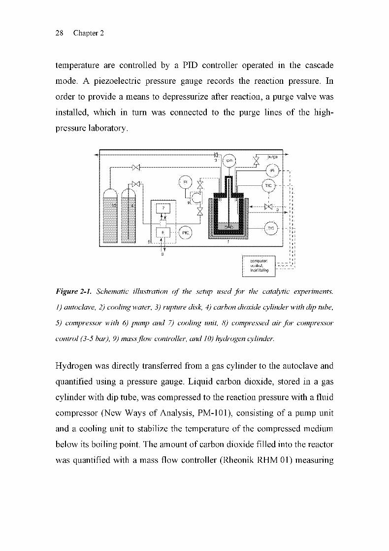
Figure 2-1. Schematic illustration of the setup used for the catalytic experiments.
1) autoclave, 2) cooling water, 3) rupture disk, 4) carbon dioxide cylinder with dip tube,
5) compressor with 6) pump and 7) cooling unit, 8) compressed air for compressor
control (3-5 bar), 9) massflow controller, and 10) hydrogen cylinder.
Hydrogen was directly transferred from a gas cylinder to the autoclave and
quantified using a pressure gauge. Liquid carbon dioxide, stored in a gas
cylinder with dip tube, was compressed to the reaction pressure with a fluid
compressor (New Ways of Analysis, PM-101), consisting of a pump unit
and a cooling unit to stabilize the temperature of the compressed medium
below its boiling point. The amount of carbon dioxide filled into the reactor
was quantified with a mass flow controller (Rheonik RHM 01) measuring

Experimental 29
the Coriolis force. Catalyst and reactant were weighed gravimetrically and
poured into the reactor before it was closed and flushed with hydrogen.
2.1.2 Apparatus for Synthesis of Catalysts in the Presence of UV-Light
The catalyst synthesis described in chapter 7 required a specially designed
vessel to allow the irradiation of the reactants with ultraviolet light
(Figure 2-2). For this purpose, an ultraviolet lamp made by Osram
(Ultramed FDA R7s, 400 W) was placed in a UV-light permeable double
wall quartz flask. The ultraviolet lamp was cooled directly by pressurized
air as well as by cooling water running between the two walls. This quartz
flask was enclosed by a second flask with an inlet and an outlet to allow
flushing with argon during the air-sensitive reaction. The whole UV-light
reactor was operated in a metallic box designed to protect the eyes against
ultraviolet light.
Electrical power and
cooling air for UV lamp fIIssssssssssœssssssssJiylL
Figure 2-2. Schematic illustration of the apparatusfor ultraviolet irradiation (left) and
a photograph of the complete apparatus (right) with the protecting box behind the
power unit and the temperature control unit.

30 Chapter 2
Prior to the experiment, the quartz flask was kept in a drying oven for 24 h.
The flasks were installed in the protecting metal box and were evacuated
and recharged with argon three times. Syringes were used to fill the
reactants in the reactor. During the exposure time, the reaction mixture was
flushed permanently by a small argon stream while stirring the reaction
mixture slowly. After irradiation, the product mixture was removed with a
syringe and stored in argon in a Schlenk flask for further processing.
2.1.3 View-cell for Phase Behavior Studies
Phase behavior studies of the reaction mixture were performed in a
computer-controlled high-pressure view-cell of variable volume (23 -
63 ml) from SITEC, in combination with online digital video imaging and
recording [1]. The magnetically stirred view-cell consisted of a horizontal
stainless steel cylinder equipped with a sapphire window.
Digital video imaging allows observations of even minor volumes of
gaseous and liquid phases, facilitating reliable static measurements of
phase behavior at temperatures and pressures up to 200°C and 200 bar.
Typically, the reactants were first filled into the view-cell, then hydrogen
and carbon dioxide were added. The temperature was adjusted by a
thermostated oil bath, and the pressure by changing of the volume [1].
2.2 Characterization Methods
To gain information on the structure of the catalysts, they were investigated
by !H-, 29Si-, 31P-cross-polarization magic angle spinning (CP-MAS)
NMR, nitrogen physisorption (BET), elemental analysis (EA), X-ray
photoelectron spectroscopy (XPS), attenuated total reflection infrared
spectroscopy (ATR-IR), diffuse reflectance infrared Fourier transform

Experimental 31
spectroscopy (DRIFTS), and X-ray absorption spectroscopy (XANES and
EXAFS). The metal content of the catalysts and liquid reaction mixtures
were measured by inductively coupled plasma optical emission
spectroscopy (ICP-OES). The structural and analytical methods are well
described in the pertinent literature [2-14] and the reader is referred to these
sources for further information. Since XANES and EXAFS were used in a
number of experiments in this work, they are described in chapter 3. The
following paragraphs describe special experimental setups and
spectroscopic cells, which were specifically developed for this work.
2.2.1 X-ray Absorption Spectroscopy Cell for Catalyst Studies in
Liquid Phase
To identify the structure of homogeneous catalysts formed under reaction
conditions, the liquid reaction mixtures were investigated by XANES and
EXAFS after reaction. For this purpose, a specially designed stainless steel
XAS cell was used for transmission experiments (Figure 2-3). Because of
the low ruthenium concentration in the reaction mixtures in the range of
50-100 ppm, a long path length of 4 cm was required, using windows
with a 6 mm x 11 mm cross section. On both sides of the cell,
exchangeable Kapton windows were employed.
The cell can be filled from the top and has a volume of 2 ml. A 1 mm x
10 mm X-ray beam was aligned with the center of the spectroscopic cell
using an x, y, 9-table from Newport.
In addition, an EXAFS cell suitable for both transmission and fluorescence
mode was constructed with similar technical dimensions as those chosen
for the XAS cell for liquid samples (Figure 2-4). The cell was equipped

32 Chapter 2
with a 10 mm x 20 mm large window positioned at a 90° angle with respect
to the X-ray beam.
window equippedwith Kapton
Figure 2-3. Stainless steel XAS cell for structural identification of the catalytically
active speciesformed in the liquidphase during reaction.
This allowed recording EXAFS spectra in the fluorescence mode at a 90°
angle to the beam. Fluorescence spectra at the Ru K-edge were recorded
using a 13-element Ge fluorescence detector (Canberra) at the Swiss
Norwegian Beamline in Grenoble (for further details, cf. chapter 7,
section 7.3.5).
Kapton
Figure 2-4. Stainless steel XAS cell for fluorescence and transmission mode for
structural identification of the catalytically active species formed in the liquid phase
during reaction.

Experimental 33
2.2.2 High-pressure XAS Cell for Studying Simultaneously the Liquid
Phase and the Solid/Liquid Interface
While the spectroscopic cells in section 2.2.1 allowed recording spectra on
homogeneous catalytic species after reaction, in many cases, in situ
monitoring of structural changes of a catalyst are required that occur at the
solid/liquid interface and in the bulk fluid phase. This approach is
advantageous if homogeneous catalytic species formed from a
heterogeneous catalyst and some ligands are dissolved in the reaction
mixture. Therefore, a spectroscopic batch reactor cell was designed that
allows in situ monitoring of the changes occurring in the bulk liquid as well
as at the liquid/solid interface of heterogeneous reactions at elevated
pressure and temperature. Hence, the dimensions of the high-pressure cell
were chosen to monitor the liquid/solid interface at the bottom of the cell
with a path length of 4 mm, and the liquid part with a path length of 15 mm
at a height of 10 mm above the bottom of the reactor cell (Figure 2-5). The
total volume of the batch reactor is 10 ml.
The inner part of the cell consists of a PEEK (polyetheretherketone, density
1.3 g/cm3) container, which has also high chemical resistance against acids,
organic solvents, and alkaline media. As Figures 2-5 and 2-6 show, this
container is embedded in a stainless steel cell. Apart from its corrosion-
resistance, PEEK was chosen for its high transparency for X-rays above
9 keV, which is better than many other chemically resistant thermoplastics
such as teflon. At 250°C, the operating temperature of this material is
rather high for a thermoplastic. As depicted in Figures 2-5 and 2-6, four
windows of 5 mm x 1 mm size inside the stainless steel container serve to
let the X-ray beam pass through the batch reactor cell at two positions (see
X-ray paths in Figure 2-6). In order to prevent damages of the PEEK

34 Chapter 2
container at high pressure, 0.5 mm thick Be disks (7.8 mm diameter,
Brushwellman) were placed between the PEEK container and the windows
in the stainless steel container. Note that the PEEK polymer itself has a
high tensile strength and therefore Be disks are not necessary at
temperatures up to 150°C.
Gas inlets, thermocouple
pressure transducer
Top cover with
PEEK inset
"eflon O-ring
EEK inset
Stainless steet bodywith cartridgee windowsX-ray beam at
two positions
Magnetic stirrer
with motor
Figure 2-5. A schematic representation of the apparatus designed for in situ X-ray
absorption spectroscopy studies with two pathways to monitor the soliddiquid interface
ofheterogeneous catalysts and the liquidphase or soliddiquid reactions.
The temperature of the batch reactor cell is adjusted using two 160 Watt
cartridge heaters (SUVAG) inserted at both sides of the stainless steel cell.
Temperature control is carried out by a commercial KS 20-1 controller
(PMA, Omni Ray) by help of a NiCr/Ni thermocouple inside the stainless
mantle. The reaction temperature is measured within the reactor. Stirring is
provided by a magnetic stirrer. In the interest of a mechanically compact
design, the thermally insulated motor, together with the magnet, was

Experimental 35
installed below the batch reactor cell. Finally, a burst plate was installed for
safety reasons.
Figure 2-6. Three-dimensional views ofthe spectroscopic batch reactor cell with PEEK
container and magnetic stirrer.
Another crucial point is the alignment of the cell in the X-ray beam. For
this purpose, the whole cell is mounted on a x, z, 9-table as shown in
Figure 2-7. This is very similar to the principle we used for a high-pressure
continuous flow cell [15]. The apparatus can be moved between the two
positions using the z-translation. Another important part of the sample cell
is the sealing. This is achieved using an appropriate cover and a
polytetrafluoroethylene (PTFE) sealing. Again, PEEK is used inside the
cover, but two different designs were brought into action, depending on the
experiment to be performed. Note that the whole setup was placed inside a
safety box (Figure 2-7).

36 Chapter 2
Figure 2-7. View ofthe batch reactor cell in the experimental hall ofthe beamline XI at
HASYLAB (DESY, Hamburg), details see text.
The cover shown in Figures 2-5 - 2-7 was adapted for reactions with
supercritical carbon dioxide and gases being present in the reaction. It has
an inlet and an outlet, both equipped with a valve, a burst plate (Swagelok,
190 bar), a pressure transducer (Wika), and the appropriate gas or liquid
supply system. For gases, the appropriate gas mixture was filled into the
batch reactor cell to the desired gas pressure. Liquid carbon dioxide was
dosed using a C02-compressor unit (NWA PM-101) with a Rheonik flow
controller (RHMO15).

Experimental 37
2.3 Catalytic Tests
2.3.1 Experimental Procedure
The amount of the amine and the catalyst were weighed and added to the
batch reactor before closing and flushing three times with hydrogen. Then,
60 bar of hydrogen was added and heated to 100°C while stirring at
300 min-1. As soon as the temperature was stabilized, the hydrogen
pressure was adjusted to the desired value of 80 bar, if not specified
differently. The reaction was started by adding liquid carbon dioxide,
quantified by a mass flow controller. To stop the reaction, the autoclave
was cooled to room temperature and vented slowly. Note that special care
had to be taken during cleaning. The reactor cleaning procedure involved
two washing steps, one with distilled water and one with acetone, followed
by drying completely.
2.3.2 Analysis
The product mixture at the bottom of the reactor was analyzed by a gas
Chromatograph (HP-6890) equipped with a HP-5 capillary column (30 m x
0.32 mm x 0.25 jiim) and a flame ionization detector (FID). Three drops of
the reaction mixture were dissolved in ethanol, and 1.0 jlxI of the resulting
solution was injected in the GC inlet at 190°C with a split ratio of 20:1. For
3-methoxypropylamine, the oven temperature was held at 35°C for 5 min,
heated to 200°C at a rate of 10°C/min, and held constant for another 5 min.
The final temperature of 250°C was reached at a rate of 75°C/min, with an
additional holding time of 8 min. The FID was set to 250°C. For
quantitative analysis, a calibration curve was recorded to calculate the
product/reactant ratio from the measured peak area. This analysis
38 Chapter 2
procedure was optimal for the reaction mixture of 3-methoxypropylamine.
It was modified slightly in the case of other amines.
Formamide products were identified with GC-MS, lH- and 13C-nuclear
magnetic resonance (NMR).
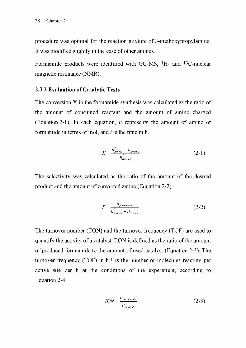
2.3.3 Evaluation of Catalytic Tests
The conversion X in the formamide synthesis was calculated as the ratio of
the amount of consumed reactant and the amount of amine charged
(Equation 2-1). In each equation, n represents the amount of amine or
formamide in terms of mol, and t is the time in h.
fl — fly amine amine /O 1 \
n°amine
The selectivity was calculated as the ratio of the amount of the desired
product and the amount of converted amine (Equation 2-2).
ci formamide /r\ r\ \
n° —namm e a mm e
The turnover number (TON) and the turnover frequency (TOF) are used to
quantify the activity of a catalyst. TON is defined as the ratio of the amount
of produced formamide to the amount of used catalyst (Equation 2-3). The
turnover frequency (TOF) in h-1 is the number of molecules reacting per
active site per h at the conditions of the experiment, according to
Equation 2-4.
n
Tf)M —
formamide O-li}
ncatalyst

Experimental 39
rps-\ y-i formamide /r\ a \
nt1 t-t
catalyst
2.4 References
[I] R. Wandeler, N. Künzle, M. S. Schneider, T. Mallat, A. Baiker, J.
Catal. 200(2001)377.
[2] A. Baiker, Chimia 35 (1981) 408.
[3] J. W. Niemantsverdriet, Spectroscopy in Catalysis, VCH, Weinheim
(1995).
[4] G. Ertl, H. Knözinger, J. Weitkamp, Handbook of Heterogeneous
Catalysis, Wiley-VCH, Weinheim (1997).
[5] B. Imelik, J. C. Védrine, Catalyst Characterization: Physical
Techniquesfor SolidMaterials, Plenum Press, New York (1994).
[6] B. M. Weckhuysen, In-situ Spectroscopy of Catalysts, American
Scientific Publishers, Stevenson Ranch, CA (2004).
[7] H. Friebolin, Ein- und zweidimensionale NMR-Spektroskopie, VCH,
Basel (1992).
[8] R. Voelkel, Angew. Chem. 100 (1988) 1525.
[9] K. L. Walther, A. Wokaun, A. Baiker, Mol. Phys. 71 (1990) 769.
[10] R. K. Harris, Analyst 110 (1985) 649.
[II] M. Hesse, H. Meier, B. Zeeh, Spektroskopische Methoden in der
organischen Chemie, Thieme, Stuttgard (1987).
[12] J. F. Watts, J. Wolstenholme, An Introduction to Surface Analysis by
XPSandAES, Wiley, Chichester (2003).

40 Chapter 2
[13] D. C. Koningsberger, R. Prins, X-Ray Absorption: Principles,
Applications, Techniques of EXAFS, SEXAFS, and XANES, Wiley,
New York (1988).
[14] H. Günzler, H.-U. Gremlich, IR Spectroscopy: An Introduction,
Wiley-VCH, Weinheim (2002).
[15] J.-D. Grunwaldt, M. Caravati, M. Ramin, A. Baiker, Catal. Lett. 90
(2003)221.

Chapter
Catalyst Characterization under Reaction
Conditions Using XANES and EXAFS
3.1 Summary
In the first part of this chapter, X-ray absorption spectroscopy for catalyst
characterization in terms of X-ray absorption near edge structure (XANES)
and extended X-ray absorption fine structure (EXAFS) is introduced. Using
EXAFS, information on the local structure of the absorber atom, such as
the kind of its nearest neighbor atoms, their distances and coordination
numbers can be extracted. XANES gives a "fingerprint" of the electronic
structure and the symmetry. Hence, X-ray absorption spectroscopy can
provide information on the structure of heterogeneous catalysts, even if the
material is X-ray amorphous. Another important advantage of
XANES/EXAFS is the possibility to gain this information in situ, even
under the high-pressure conditions required in this work.
In the second part of this chapter, the potential of such in situ studies
employing a batch-like reactor cell that allows measurements of both the
solid catalyst and the dense liquid-like phase (the reaction mixture) under
high-pressure conditions is shown. For this purpose, one X-ray path probes
the bottom, while the other X-ray path penetrates the center of the in situ
cell. The principles of X-ray absorption spectroscopy are explained and
3
42 Chapter 3
illustrated with the help of examples from the ruthenium-catalyzed
formylation of amines in supercritical carbon dioxide in the presence of
hydrogen.
3.2 Introduction
X-ray absorption spectroscopy (XAS) using synchrotron radiation is a
powerful tool for the characterization of solid materials [1-3]. Together
with other complementary techniques, such as X-ray diffraction (XRD),
infrared spectroscopy (IR), electron spin resonance (ESR, EPR), or Raman
spectroscopy, it is a well-established characterization method in hetero¬
geneous catalysis [3-13]. As shown in Figure 3-1, two regions can be
distinguished, the X-ray absorption near edge structure (XANES) and the
extended X-ray absorption fine structure (EXAFS). The spectrum in the
near edge region is characterized by electronic transitions and multiple
scattering effects. Therefore, it provides a means to obtain information
about the electronic properties and the local structure (symmetry) of the
absorbing atom. The EXAFS region is dominated by single-scattering
events of the outgoing electron wave at the neighboring atoms, giving
information about the local atomic structure around the absorber atom. The
fact that the samples under investigation can be amorphous leads to
important advantages of using XANES/EXAFS in the field of the
heterogeneous catalysis [1,2], since they involve primarily large surface
areas and often amorphous materials.
Another advantage of the XANES/EXAFS technique is the possibility to
investigate the solid catalyst under in situ reaction conditions, as well as
any species dissolved in the liquid phase owing to the good penetration
characteristics of hard X-rays. Only a few techniques, such as IR [14, 15],

Catalyst Characterization In Situ Using XANES and EXAFS 43
NMR [16,17], UV-vis [18,19], Raman [15,20], and EPR [21,22]
spectroscopy, allow in situ studies on heterogeneous catalysts in super¬
critical fluids. In the past decades, only a small number of studies in gas-
solid reactions [3, 23-29] and on solid-liquid interfaces [30-33] at high
temperatures and pressures have taken advantage of the potential of X-ray
absorption spectroscopy. High-pressure reactions of this kind involve not
only a liquid phase, but also solids encountered in various fields of
chemistry, including heterogeneous catalysis [34-37]. For the elucidation of
the reaction mechanism, information on the solid and possibly the
dissolved species under reaction conditions is required concurrently. X-ray
absorption spectroscopy is a valuable method to gain this kind of
information under in situ conditions.
3.3 Basics ofXANES and EXAFS
The basis of X-ray absorption spectroscopy is the absorption of X-rays by
excitation of a core electron to an empty state or continuum (Figure 3-1).
The absorption of the X-rays can be described with Lambert-Beer's law
and is a function of the energy of the exciting X-rays. If the energy is high
enough to excite the core electrons, X-ray absorption is observed, which
leads to an absorption edge. In solid materials, metallic complexes and
clusters in solution, not only an absorption step is visible, but also an
oscillatory fine structure as depicted in Figure 3-1 at 21 keV at the Ru K-
edge.
In 1923, Kronig [38, 39] observed the first extended X-ray absorption fine
structure that was explained in 1971 by Sayers, Stern, and Lytle [40, 41].
The fine structure above the edge can be attributed to interferences from
the outgoing electron wave and the electron wave that is backscattered at

44 Chapter 3
the neighboring atoms. The resulting characteristic oscillations, called the
EXAFS function x(k), exhibits maxima and minima caused by positive and
negative interferences. The EXAFS function depends on the kind of the
neighboring atoms, their distances and their number.
Figure 3-1. Principle of X-ray absorption: schematic representation for a) the
excitation of a core electron and b) the scattering of the electron wave at the
neighboring atom and c) the spectrum of RuClß at the K-edge with the XANES and
EXAFS region.
With the single scattering approximation, the EXAFS function x(k) can be
calculated using Equation 3-1, assuming that the photoelectron scatters
only once during its lifetime [42].
%(k) = TNSl{k)F(k)e-^kle-^^k) sin(-2krs+Mk»(3.1)
Yj represents the distance between the absorber atom i and the neighboring
atoms in the shell j, Nj is the number of neighboring atoms in the shell j,
F;(k) is the backscattering amplitude, §[\(k) is the phase shift experienced

Catalyst Characterization In Situ Using XANES and EXAFS 45
by the photoelectron in the scattering process. So2(k) is the amplitude
reduction factor, causing some damping of the signal. The exponential
terms with the Debye-Waller factor a2 and the mean free path length X are
additional damping factors. The mean free path length X of only a few Â
makes EXAFS an ideal local sampling technique.
In practice, the white X-rays typically used at a synchrotron are
monochromized using a double crystal such as Si(lll) or Si(311). In this
way, a spectrum can be taken by scanning the energy region step by step
around the element-specific near edge region of the sample. The intensity
before and after traversing the sample can be recorded with two ionization
chambers, located before and after the sample. Energy calibration may be
achieved by placing a reference foil between the second and an additional
third ionization chamber. Aside from this transmission experiment, data
can also be taken in the fluorescence mode [2, 3]. The fluorescence mode is
the preferred choice if the concentration of the atoms of interest is low and
no reasonable signal-to-noise ratio can be obtained in transmission
mode [43].
In summary, XANES gives a "fingerprint" of the structure, such as
oxidation state and symmetry around the absorber atom, while the EXAFS
region can reveal the structure of the nearest neighbors, such as distances
and coordination numbers. The result of the Fourier transformation of the
EXAFS data is a radial distribution function.
As an example, Figure 3-2 shows the EXAFS spectra of RuCl2(dppe)2 and
RuCl2(PPh3)3 and the corresponding Fourier-transformed EXAFS
functions, taken in the liquid phase around the Ru K-edge at 22.117 keV.
Due to the high energy of the Ru K-edge, the contribution of the solvent to
the absorption is very small. The structure of Ru phosphine complexes can

46 Chapter 3
also be identified even at very low concentrations (-50 ppm). In these
cases, the spectra are preferably taken in the fluorescence mode [44]. As
demonstrated in chapter 7, section 7.4.4, even the transmission mode is
suitable under certain circumstances, down to a concentration of about
200 ppm.
22 10 22 12 22 14 22 16 22 18 22 20
E/keV3
R/Â
Figure 3-2. a) EXAFS spectra of RuCE(dppe)2 and RuCEfPPhj)^ with b) the
corresponding Fourier-transformed spectra (taken in transmission mode).
In the example shown in Figure 3-2, the spectrum of RuCl2(dppe)2 differs
significantly from that of RuCl2(PPli3)3, both in the XANES and in the
EXAFS region, the reason being the different symmetry and the different
number of phosphine ligands using dppe and PPI13, respectively. Also, the
peaks in the Fourier-transformed spectra are slightly different, but both
structures exhibit a backscattering peak at 1.8 and 2.5 Â. Note that the
spectra presented here are not phase-shift-corrected. The backscattering
contribution of RuCi2(dppe)2 is much smaller than that of RuCi2(PPli3)3.
Analysis of the EXAFS data - by fitting with Ru-P and Ru-Cl shells using
FEFF 6.0 [45] and WinXAS 3.0 [46] - yields the type, the distance, and the
number of the nearest neighbors. The fitting procedure is a multiparameter
problem requiring a careful data analysis procedure. The structural data

Catalyst Characterization In Situ Using XANES and EXAFS 47
obtained for RuCl2(PPli3)3 (see Table 4-1 in chapter 4) are in accordance
with literature [47]. Three different Ru-P bond lengths at 2.23, 2.37, and
2.41 Â and two Ru-Cl bond lengths at 2.387 and 2.388 Â were reported by
single crystal X-ray diffraction. In our studies, only one Ru-P distance at
2.22 Â and a contribution at a higher value of 2.93 Â were found. This can
be attributed to the fact that the measured catalyst was dissolved in the
reaction mixture, and that the EXAFS technique cannot differentiate
between neighbors that are close to each other. In RuCl2(dppe)2, dissolved
in the reaction mixture, a Ru-P distance of 2.32 Â was found in close
accordance with single crystal X-ray diffraction data reported in ref. [48].
3.4 High-pressure In Situ X-ray Absorption Spectroscopy
With XANES and EXAFS, in situ studies on the structure of catalysts
under reaction conditions can be carried out. The penetration of X-rays at
the Ru K-edge both through the solvent and through window materials such
as Be is quite good. Note that CO2 results in 25% absorption over a
distance of 10 mm and Be absorbs even less [42]. Such studies are of great
importance in heterogeneous catalysis, since in situ experiments can
elucidate information about the catalyst structure, which may be very
different from the structure the catalyst exhibits after air exposure. If the
catalyst structure changes under reaction conditions, the relationship
between structure and activity can hardly be determined with ex situ
experiments. Considering the dramatic influence of the high-pressure
reaction conditions on the structure of the catalyst, in situ studies are of
particular importance. Monitoring both the solid catalyst under reaction
conditions and the catalytic species dissolved in the liquid reaction phase at
the same time can lead to a better understanding of the role of possible

48 Chapter 3
dissolved catalyst species. Therefore, this approach can show whether the
reaction is homogeneously or heterogeneously catalyzed (see next section).
In order to get some answers in this context, a specially designed high-
pressure in situ EXAFS cell was constructed, which allows determining the
best compromise between the spectroscopic technique and the reaction
conditions for catalysis. For details of the cell, see chapter 2, section 2.2.2.
The capabilities of this approach are illustrated in the following case study.
3.5 Case Study: Ruthenium-catalyzed Formylation of
3-Methoxypropylamine with Hydrogen and Supercritical
Carbon Dioxide
3.5.1 Introduction
Formylation of amines with supercritical carbon dioxide (SCCO2) and
hydrogen using ruthenium based phosphine complexes is a well-known
"green" process [49-55]. Important products such as A^/V-dimethyl-
formamide and TV-formylmorpholine can be produced in this way. Usually,
homogeneous catalysts were used, and only a few heterogeneous catalysts
have been reported for this reaction [56, 57].
Recently, we found that RU/AI2O3 in the presence of 1,2-bis(diphenyl-
phoshino)ethane (dppe) also shows good activity [58]. In order to get more
insight into the role and the mechanism of this new catalyst, the new in situ
batch reactor cell was used and tested in the formylation of
3-methoxypropylamine with carbon dioxide and hydrogen.
For this purpose, both the solid catalyst and the liquid phase were first
investigated during the formylation without dppe, and then, in a second
step, in the presence of dppe.

Catalyst Characterization In Situ Using XANES and EXAFS 49
3.5.2 Experimental
X-ray Absorption Spectroscopy Measurements and Data Analysis. The in
situ X-ray absorption spectroscopy experiments were performed at
beamline XI of the Hamburger Synchrotron Laboratory (HASYLAB) at
Deutsches Elektronen-Synchrotron (DESY, Hamburg, Germany). The
beam size was cut to 5 x 1 mm and the in situ batch reactor cell was aligned
using the x, z, 9-table. The beamline is equipped with Si(311) and Si(lll)
double crystal monochromators which were detuned to 60% to reduce the
amount of higher harmonics. Three ionization chambers were used to
measure the incident and outcoming X-ray intensities, located before and
after the in situ cell, as well as after a suitable reference foil for energy
calibration. The ionization chamber gases (Ar, N2, Kr, depending on the
energy of the absorption edge) and their pressure were adjusted in such a
way that about 10% were adsorbed in the first ionization chamber and 40%
in the second and third ionization chambers.
Typical scans at the Ru K-edge were recorded in the following way. For
the solid catalyst or the liquid phase under static conditions or after
equilibration, spectra between 21.900 and 23.500 keV were taken in the
step scanning mode. Faster scans in the continuous scanning mode
(QEXAFS) were recorded between 22.065 and 22.665 keV (0.15 s/eV)
during dynamic changes of the structure. As reference for energy
calibration, RUCI3 (pressed as self-supporting wafer with BN) and Ru foil
were used. 5 wt-% RU/AI2O3 (Engelhard) served as catalyst material, and
l,2-bis(diphenylphosphino)ethane served as ligand. Both were used
unaltered, as received by the supplier.
The raw data were energy-calibrated with the help of the respective
reference sample/foil, background-corrected and normalized using the
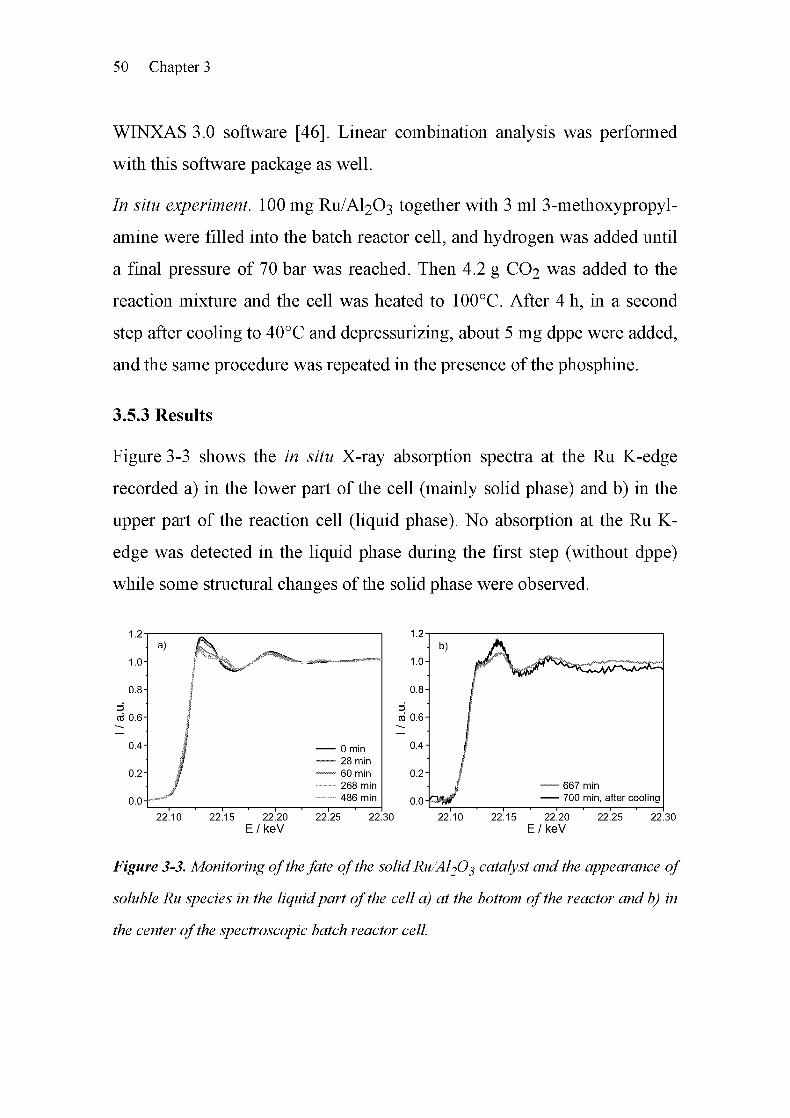
50 Chapter 3
WINXAS 3.0 software [46]. Linear combination analysis was performed
with this software package as well.
In situ experiment. 100 mg RU/AI2O3 together with 3 ml 3-methoxypropyl-
amine were filled into the batch reactor cell, and hydrogen was added until
a final pressure of 70 bar was reached. Then 4.2 g CO2 was added to the
reaction mixture and the cell was heated to 100°C. After 4 h, in a second
step after cooling to 40°C and depressurizing, about 5 mg dppe were added,
and the same procedure was repeated in the presence of the phosphine.
3.5.3 Results
Figure 3-3 shows the in situ X-ray absorption spectra at the Ru K-edge
recorded a) in the lower part of the cell (mainly solid phase) and b) in the
upper part of the reaction cell (liquid phase). No absorption at the Ru K-
edge was detected in the liquid phase during the first step (without dppe)
while some structural changes of the solid phase were observed.
22.10 22.15 22.20 22.25 22.30 22.10 22.15 22.20 22.25 22.30
E / keV E / keV
Figure 3-3. Monitoring ofthe fate of the solid Ru/Al20^ catalyst and the appearance of
soluble Ru species in the liquidpart of the cell a) at the bottom of the reactor and b) in
the center ofthe spectroscopic batch reactor cell.

Catalyst Characterization In Situ Using XANES and EXAFS 51
The so-called whiteline at 22.12 keV decreased, indicating that the solid
ruthenium-based catalyst was in oxidized state at the beginning of the
experiment, but was reduced in the presence of hydrogen.
Reconstructing the spectra from the initial spectrum (oxidized ruthenium
species) and a reference Ru foil (chosen energy range for linear
combination of the spectra: 22.07 - 22.26 keV) allowed to quantify the
fraction of metallic Ru species in the catalyst. The results are shown in
Figure 3-4.
0 9-
5 jg 0 8-
100 is I'œ0 7-
10-^b)
60 M
ceu°-
b .0 0 4-<0 r- =
40 £o 3 0 3-
II 02-
it 0 1-
0 0-
\
300 400 500
Time / min
0 100 200 300 400 500
Time / min
Figure 3-4. a) Temperature and pressure during the experiment as function of time
(dppe was added after 450 min); b) Quantification of the reduced (bullets) and oxidized
(squares) ruthenium species on the solid catalyst determined by linear combination
analysis (left), and the relative concentration of the dissolved Ru species in the liquid
phase (triangles, final concentration ca. 200 ppm) as determined from the X-ray
absorption step.
It is obvious that the reduction occurred steadily during heating to 100°C.
A further increase of the reaction temperature to 120°C led to slightly more
reduction. Nevertheless, the absorption at the Ru K-edge in the liquid phase
is marginal. Only at very high stirring rates (between t = 250 and 350 min,
Figure 3-4), a small signal of Ru species in the solution could be found,
probably because some of the catalyst formed a suspension. However, as
52 Chapter 3
soon as dppe was added to the reaction mixture, a significant signal in the
upper part of the cell - which reflects the liquid part of the reaction
mixture - was observed. Two spectra are shown in Figure 3-3b. These
results clearly show that the catalyst was partially dissolved, probably due
to the strongly complexing and thus corrosive action of the phosphine
ligand. Interestingly, the concentration of about 200 ppm is sufficient to
catalyze the formylation of 3-methoxypropylamine and the role of these
dissolved Ru species is discussed in more detail in chapter 5.
3.5.4 Discussion
A high-pressure reactor cell suitable for X-ray absorption spectroscopy and
its application in a case study of catalysis has been described. The
technique makes use of the applicability of X-ray absorption spectroscopy
to solid amorphous materials and to structural identification in liquid phase.
In this way, reactions can be studied where both the solid/liquid interface
and the liquid phase need to be monitored. In catalysis, the question
frequently arises, whether the reaction is homogeneously or hetero¬
geneously catalyzed. Because of the high sensitivity and the element-
specificity of XAS, even small concentrations can be detected in solution.
In the case study, it was found that a homogeneous Ru complex formed
upon addition of a phosphine (dppe) ligand, and the resulting catalyst is
thus homogeneous. Recently, Köhler et al. [59] observed that a soluble Pd
catalyst was formed from supported palladium after a short induction time
during the Heck coupling of bromo benzene with styrene. In this case, one
of the reactants served as ligand to dissolve the heterogeneous catalyst.
When the reaction was finished, the catalytically active complex
decomposed again. In that study, the homogeneous species were merely
identified by elemental analysis of the liquid mixture. The present approach

Catalyst Characterization In Situ Using XANES and EXAFS 53
using X-ray absorption spectroscopy allows the identification of both the
structure and the concentration of the catalytically active species in situ -
this may prove to be especially important if the homogeneous species are
observed under reaction conditions only.
3.5.5 Conclusions
The case study illustrates that the new in situ cell is well-suited to follow
heterogeneously catalyzed reactions in SCCO2 or similar solvents at
pressures of up to 200 bar. The cell fills the gap between recently designed
setups for heterogeneously catalyzed reactions in continuous flow cells
[60, 61] and homogeneously catalyzed reactions [62].
3.6 References
[1] B. B. Theo, EXAFS: Basic Principles and Data Analysis, Springer,
Berlin (1986).
[2] D. C. Koningsberger, R. Prins, X-Ray Absorption: Principles,
Applications, Techniques of EXAFS, SEXAFS, and XANES, Wiley,
New York (1988).
[3] Y. Iwasawa, X-ray Absorption Fine Structure for Catalysts and
Surfaces, World Scientific, Singapore 2 (1996).
[4] J. M. Thomas, G. N. Greaves, C. R. A. Catlow, Nucl. Instr. Meth.
Phys. Res. B 97 (1995)1.
[5] G. Vlaic, D. Andreatta, P. E. Colvita, Catal. Today 41 (1998) 261.
[6] B. S. Clausen, Catal. Today 39 (1998) 293.
[7] B. S. Clausen, H. Topsoe, R. Frahm, Adv. Catal. 42 (1998) 315.
[8] J. M. Thomas, Angew. Chem. Int. Ed. 38 (1999) 3588.

54 Chapter 3
[9] D. Bazin, C. Mottet, G. Treglia, J. Lynch, Appl. Surf. Sei. 164
(2000) 140.
[10] G. Sankar, J. M. Thomas, C. R. A. Catlow, Topics Catal. 10 (2000)
255.
D. Bazin, C. Mottet, G. Treglia, Appl. Catal. A 200 (2000) 47.
J. M. Thomas, G. Sankar, J. Synchr. Rad. 8 (2001) 55.
D. Bazin, L. Guczi, Appl. Catal. A 213 (2001) 147.
G. Laurenczy, F. Lukacs, R. Roulet, Anal. Chim. Acta 359 (275)
275.
M. Poliakoff, S. M. Howdle, S. G. Kazarian, Angew. Chem. Int. Ed.
Engl. 34 (1995) 1275.
J. Jonas, High Pressure NMR, P. Diehl, E. Fluck, H. Günther, R.
Kosfeld, J. Seelig, Springer Verlag, Berlin, Heidelberg 24 (1990).
I. T. Horvath, J. M. Millar, Chem. Rev. 91 (1991) 1339.
S. Kim, K. P. Johnston, Ind. Eng. Chem. Res. 26 (1987) 1206.
J. Lu, B. Han, H. Yan, Phys. Chem. Chem. Phys. 1 (1999) 3269.
S. BrunsgaardHansen, R. W. Berg, E. H. Stenby, Appl. Spectr. 55
(2001)745.
S. Ganapathy, T. W. Randolph, C. Carlier, J. A. O'Brien, Int. J.
Thermophys. 17 (1996) 471.
J. L. deGrazia, T. W. Randolph, J. A. O'Brien, J. Phys. Chem. A. 102
(1998) 1674.
J.-D. Grunwaldt, L. Basini, B. S. Clausen, J. Catal. 200 (2001) 321.

Catalyst Characterization In Situ Using XANES and EXAFS 55
[24] K. K. Bando, T. Saito, K. Sato, T. Tanaka, F. Dumeignil, M.
Imamura, N. Matsubayashi, H. Shimada, J. Synchr. Rad. 8 (2001)
581.
[25] J.-D. Grunwaldt, B. S. Clausen, Top. Catal. 18 (2002) 37.
[26] T. Ressler, J. Wienold, R. E. Jentoft, T. Neisius, M. M. Günther,
Topics Catal. 18(2002)45.
[27] R. Revel, D. Bazin, A. Seigneurin, P. Barthe, J. M. Dubuisson, T.
Decamps, H. Sonneville, J. J. Poher, F. Maire, P. Lefrancois, Nucl.
Instr. Meth. Phys. Res. B 155 (1999) 183.
[28] P. Kappen, J.-D. Grunwaldt, B. S. Hammershoi, L. Tröger, G.
Materlik, B. S. Clausen, J. Catal. 198 (2001) 56.
[29] J.-D. Grunwaldt, P. Kappen, L. Basini, B. S. Clausen, Catal. Lett. 78
(2002) 13.
[30] G. Sankar, F. Rey, J. M. Thomas, G. N. Greaves, A. Corma, B. R.
Dobson, A. J. Dent, Chem. Commun. (1994) 2279.
[31] A. P. Markusse, B. F. M. Küster, D. C. Koningsberger, G. B. Marin,
Catal. Lett. 55(1998)141.
[32] H. H. C. M. Pinxt, B. F. M. Küster, D. C. Koningsberger, G. B.
Marin, Catal. Today 39 (1998) 351.
[33] A. Edelmann, W. Schiesser, H. Vinek, A. Jentys, Catal. Lett. 69
(2000)11.
[34] B. Subramaniam, M. A. McHugh, Ind. Eng. Chem. Des. Dev. 25
(1986)1.
[35] A. Baiker, Chem. Rev. 99 (1999) 453.

56 Chapter 3
[36] J.-D. Grunwaldt, R. Wandeler, A. Baiker, Catal. Rev. -Sei. Eng. 45
(2003)1.
[37] P. G. Jessop, W. Leitner, Chemical Synthesis Using Supercritical
Fluids, Wiley-VCH, Weinheim (1999).
[38] R. D. Kronig, Z. Phys. 70 (1931) 317.
[39] R. D. Kronig, Z. Phys. 75 (1932) 468.
[40] D. E. Sayers, E. A. Stern, F. W. Lytle, Phys. Rev. Lett. 27 (1975)
4836.
[41] F. W. Lytle, J. Synchr. Rad. 6 (1999) 123.
[42] J.-D. Grunwaldt, A. Baiker, Phys. Chem. Chem. Phys. 7 (2005)
3526.
[43] J. Jaklevic, J. A. Kirby, M. P. Klein, A. S. Robertson, G. S. Brown,
P. Eisenberger, Solid State Commun. 23 (1977) 679.
[44] S. G. Fiddy, J. Evans, T. Neisius, X. Z. Sun, Z. Jie, M. W. George,
Chem. Commun. 6 (2004) 676.
[45] S. I. Zabinsky, J. J. Rehr, A. Ankudinov, R. C. Albers, M. J. Eller,
Phys. Rev. B. 52 (1995) 2995.
[46] T. Ressler, J. Synchrotron Rad. 5 (1998) 118.
[47] S. J. LaPlaca, J. A. Ibers, Inorg. Chem. 4 (1965) 778.
[48] T. S. Lobana, R. Singh, E. R. T. Tiekink, J. Coord. Chem. 21 (1990)
225.
[49] P. G. Jessop, T. Ikariya, R. Noyori, Nature 368 (1994) 231.

Catalyst Characterization In Situ Using XANES and EXAFS 57
[50] P. G. Jessop, Y. Hsiao, T. Ikariya, R. Noyori, J. Am. Chem. Soc. 118
(1996)344.
[51
[52
[53
[54
[55
[56
[57
[58
[59
[60
[61
[62
O. Kröcher, R. A. Koppel, A. Baiker, Chimia 51 (1997) 48.
C.-C. Tai, J. Pitts, J. C. Linehan, A. D. Main, P. Munshi, P. G.
Jessop, Inorg. Chem. 41 (2002) 1606.
Y. Kayaki, Y. Shimokawatoko, T. Ikariya, Adv. Synth. Catal. 345
(2003) 175.
L. Schmid, A. Canonica, A. Baiker, Appl. Catal. A: Gen. 255 (2003)
23.
L. Schmid, M. S. Schneider, D. Engel, A. Baiker, Catal. Lett. 88
(2003) 105.
O. Kröcher, R. A. Koppel, M. Fröba, A. Baiker, J. Catal. 178 (1998)
284.
O. Kröcher, R. A. Koppel, A. Baiker, J. Mol. Catal. A: Chem. 140
(1999) 185.
M. Rohr, J.-D. Grunwaldt, A. Baiker, J. Catal. 229 (2005) 144.
S. S. Pröckl, W. Kleist, M. A. Gruber, K. Köhler, Angew. Chem. Int.
Ed. 43(2004)1881.
J.-D. Grunwaldt, M. Caravati, S. Hannemann, A. Baiker, Phys.
Chem. Chem. Phys. 6 (2004) 3037.
J.-D. Grunwaldt, M. Caravati, M. Ramin, A. Baiker, Catal. Lett. 90
(2003)221.
S. L. Wallen, D. M. Pfund, J. L. Fulton, C. R. Yonker, M. Newville,
Y. Ma, Rev. Sei. Instrum. 67 (1996) 2843.


Chapter
A Simple Route to Highly Active Ruthenium
Catalysts for Formylation Reactions with
Hydrogen and Carbon Dioxide
4.1 Summary
A simple route to ruthenium catalysts suitable for formamide production
from amines, hydrogen, and carbon dioxide is reported. The formylation of
3-methoxypropylamine has been employed as a test reaction. Highly active
and selective ruthenium based catalysts were formed in situ under reaction
conditions from solid rutheniumtrichloride (RUCI3) in the presence of
triphenylphosphine (PPI13) and l,2-bis(diphenylphosphino)ethane (dppe).
While RUCI3 does not catalyze the reaction efficiently, the addition of
phosphines led to a near five-fold increase in rate. The achieved turnover
frequencies are comparable to those of synthesized reference Ru-phosphine
complexes. As a consequence of the high activity, only very small amounts
(-300 ppm) of both RUCI3 and the phosphine are necessary to catalyze
effectively the formylation reaction. In spite of the very low concentration
of the Ru complex, the structure of the in situ formed active complex was
uncovered by X-ray absorption near edge structure (XANES) and extended
X-ray absorption fine structure (EXAFS) spectroscopy. Both indicated
4

60 Chapter 4
similar local structures for the in situ formed complex and a Ru-reference
complex after reaction.
4.2 Introduction
The simultaneous use of carbon dioxide in chemical synthesis as a Ci-
building block and as a solvent is an attractive strategy for green chemistry.
Toxic chemicals such as phosgene and carbon monoxide as well as
environmentally harmful organic solvents may be potentially replaced [1-
4]. One interesting route is the formylation of amines with hydrogen and
carbon dioxide in the presence of ruthenium phosphine complexes, cf.
chapter 1, section 1.3.2 [2,5,6]. For example, the ruthenium catalyzed
synthesis of dimethylformamide from dimethylamine, hydrogen and carbon
dioxide showed good results in homogeneous and heterogeneous catalysis
[3,7,8]. Apart from dimethylamine, other amines, such as propylamine
[9, 10], diethylamine [11] and morpholine [12, 13], have been investigated.
Up to now, the homogeneous catalysts used to be prepared directly,
involving complexes like RuH2(P(CH3)3)4, RuCl2(P(CH3)3)4,
RuH2(P(C6H5)3)4, and RuCl(02CCH3)(P(CH3)3)4 [9, 14, 15], or by the in
situ formation of the active complexes from [RuCl2(CgH6)]2,
RuCl2(DMSO)4, and [RuCl2(COD)]n [16]. However, the use of a simple
ruthenium salt, RUCI3, in the presence of phosphine ligands has not been
reported and tested in the solventless formylation of amines using carbon
dioxide as a Ci-synthesis block, see chapter 1, section 1.3. To our
knowledge, the only studies hinting in this direction are the formylation of
amines in hexane in the presence of a RUCI3-PPI13-THF solution covered in
the patent of Kiso et al. [17], and the synthesis of formic acid in the
A Simple Route to Ruthenium-catalyzed Formylations 61
presence of RUCI3/PPI13 in a mixture of ethanol and water as the solvent
[18].
In this chapter, it is shown that highly active Ru catalysts can be prepared
in situ by adding a suitable phosphine, l,2-bis(diphenylphosphino)ethane
(dppe) or triphenylphosphine (PPI13), to the reaction mixture containing
RUCI3 as a pre-catalyst (route 2, Figure 1-2 in chapter 1, section 1.5). We
investigated this simple in situ preparation of the catalyst using the
formylation of 3-methoxypropylamine as a test reaction. It has been shown
that the catalytic performance of the in situ generated homogeneous
catalysts is comparable to that of RuCl2(dppe)2 and RuCl2(PPli3)3
reference complexes. Both strategies lead to highly active and virtually
100% selective catalysts. Inductively coupled plasma optical emission
spectroscopy, X-ray absorption near edge structure, and extended X-ray
absorption fine structure spectroscopy were applied to gain information
about the concentration and the structure of the catalyst formed in situ from
RUCI3 and the phosphine.
4.3 Experimental
The formylation of 3-methoxypropylamine (mpa, Scheme 4-1) was chosen
as a test reaction. The reaction was carried out in a temperature-controlled
500 ml high-pressure stainless steel autoclave with a dosing system for
gases [19]. In a typical procedure, mpa and the catalyst (50 jiimol Ru,
adding the corresponding stoichiometric amount of phosphine in the case
of RUCI3) were filled into the reactor before closing and flushing with
hydrogen. The reactor was then filled with hydrogen and adjusted to a
pressure of 80 bar at 100°C. Finally, 100 g carbon dioxide was added,
resulting in a total pressure of 220 bar at 120°C. The stirring rate was fixed

62 Chapter 4
at 300 min-1. After a certain reaction time, the reactor was cooled down
and depressurized by opening the outlet valve. The reaction mixture
consisted of two phases, a dense liquid phase containing the reactant amine
and the products (formamide and water), and a less dense supercritical
carbon dioxide phase. The reaction mixture was analyzed using a gas
Chromatograph (HP-6890) equipped with a HP-5 capillary column (30 m x
0.32 mm x 0.25 jiim) and a flame ionization detector (FID). Product
identification was achieved with a gas Chromatograph (HP-6890) coupled
to a mass spectrometer (HP-5973).
scCO,, H, -H,0 H
RuCI3 in situ formed
+ — homogeneous
dppe Ru catalyst
Scheme 4-1. Formylation of 3-methoxypropylamine with hydrogen, supercritical
carbon dioxide and in the presence ofhighly active and selective ruthenium catalysts.
The X-ray absorption spectroscopy studies were performed at beamline XI
at HASYLAB (DESY). A Si(311) double-crystal monochromator was used
and higher harmonics were effectively removed by detuning the crystals to
70% of the maximum intensity. Additional experiments were performed at
SNBL (ESRF, Grenoble). EXAFS spectra were taken in the step-scanning
mode around the Ru K-edge (22.117 keV) between 21.900 and 22.800 keV
using a RUCI3 pellet as reference. Due to the low concentration of
ruthenium, a transmission EXAFS cell with a long path length of 4 cm was
used as described in chapter 2, section 2.2.1. The raw data were energy-
calibrated (Ru K-edge energy of RUCI3: 22.120 keV [20], first inflection
point), background-corrected and normalized using the WINXAS3.0
software [21]. Fourier transformation for the EXAFS data was applied to

A Simple Route to Ruthenium-catalyzed Formylations 63
the k1-weighted functions in the interval k = 3-12.5Â_l. Data fitting was
performed in R-space. Typical deviations are ±0.5 for the coordination
number and ±0.02 Â for the distance.
4.4 Results and Discussion
RUCI3 used as pre-catalyst showed only a low activity with a conversion of
12% and a turnover frequency (TOF, see definition in chapter 2,
section 2.3.3) of 19 h-1 under standard reaction conditions as denoted in
Figure 4-1. After adding dppe, the activity of the in situ formed catalyst
increased, affording a TOF of 90 Ir1 and a conversion of 95%. A similar
catalytic performance was observed when adding PPI13 instead of dppe
(Figure 4-1). The catalytic behavior of the homogeneous catalysts
RuCl2(dppe)2 and RuCl2(PPli3)3 used as references was in the same range.
The selectivity to the corresponding formamide was 100% in all reactions.
100 100
dppe
RuCI, RuCl^dppe), RuCI,(PPh,),+
PPh
Figure 4-1. Comparison ofthe performance ofcatalysts generated in situfrom RuCE +
dppe or PPh$ and related homogeneous reference catalysts RuC^fPPh^ß and
RuCE(dppe)2 in the formylation of mpa. Selectivity to formamide was 100% in all
cases. Reaction conditions: 100 mmol mpa, 50 jumol Ru catalyst, 100 g CO2, 120°C,
totalpressure 220 bar, 20 h.

64 Chapter 4
Consequently, this in situ generation offers a very simple and cheap
procedure for preparing highly active homogeneous Ru-catalysts. To
confirm the formation of complexes acting as homogeneous catalysts
formed from RUCI3 and dppe or PPI13, firstly the Ru-concentration in the
reaction mixtures after filtration and centrifugation was quantified with
ICP-OES, and secondly, pertinent tests according to Sheldon et al. [22]
were performed. Specifically, the reaction was stopped after a certain time,
the reaction mixture was filtered off, and it was checked whether the
catalytic reaction could be continued after this procedure. No significant
loss of activity could be observed. This confirmed the supposition that all
Ru-complexes formed were dissolved in the amine rich phase. After 3 h of
reaction time, 49% of the amine was converted with the catalyst RUCI3 +
dppe. Only about 300 ppm ruthenium was present in the reaction mixture.
After filtration and continuation of the reaction for a total time of 20 h, the
conversion reached 90%. In an experiment without filtration, virtually the
same conversion (88%) was found after 20 h, which proved that the
ruthenium based complex is a homogeneous catalyst formed in situ under
reaction conditions. Note that the conversion of RUCI3 + PPI13 after 3 h was
25% compared to 49% for the RUCI3 + dppe system.
This is in line with literature, where dppe complexes were found to be more
active than monophosphine complexes [8], and it also supports our
hypothesis that the Ru-phosphine complex act as homogeneous catalyst.
To gain some information about the structure of the in situ formed Ru-
complexes, the product mixtures were investigated by XANES and EXAFS
using an appropriate stainless steel cell constructed for transmission
experiments (chapter 2, section 2.2.1). As a result of the low Ru-
concentration in the product mixture, only the use of the long path length

A Simple Route to Ruthenium-catalyzed Formylations 65
(4 cm) in this cell allows structural identification even at low
concentrations. Because of the high energy of the Ru K-edge, the
contribution of the solvent to the absorption is very small [23]. This shows
that the structure of Ru-phosphine complexes can be identified even at low
concentrations. Studies on the local structure of ruthenium in systems with
such low concentrations of the target species are difficult to perform by
means of any other technique [24]. Essentially, EXAFS spectra can be
taken in two different modes: fluorescence detection or transmission mode.
Whereas Fiddy et al. [25] proposed the use of fluorescence detection, it
seemed that in our case transmission EXAFS is a viable alternative. Both
the Ru K-edge and Rh K-edge are found at rather high energies, so that the
absorption at 22 keV is only ud = 0.08. At 300 ppm of Ru concentration, an
edge jump of 1.5 was found, leading to a sufficient signal/noise ratio.
22'10'
22'12'
22'14'
22'16'
22'18'
22'20E/keV
Figure 4-2. X-ray absorption near edge structure at the Ru K-edge ofRuClß, RuClß +
dppe, RuCE(dppe)2 and RuCEfPPh^)^ All spectra were taken from the liquidproduct
mixture.
Figure 4-2 shows the XANES region of the catalysts RUCI3 + dppe and the
references RUCI3, RuCl2(dppe)2, and RuCl2(PPli3)3. Upon dppe addition,
the spectrum of RUCI3 changed significantly. From these changes, the
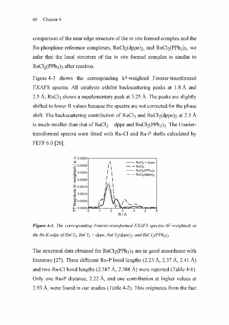
66 Chapter 4
comparison of the near edge structure of the in situ formed complex and the
Ru-phosphine reference complexes, RuCl2(dppe)2, and RuCl2(PPli3)3, we
infer that the local structure of the in situ formed complex is similar to
RuCl2(PPfi3)3 after reaction.
Figure 4-3 shows the corresponding kl-weighted Fourier-transformed
EXAFS spectra. All catalysts exhibit backscattering peaks at 1.8 Â and
2.5 Â; RUCI3 shows a supplementary peak at 3.25 Â. The peaks are slightly
shifted to lower R values because the spectra are not corrected for the phase
shift. The backscattering contribution of RUCI3 and RuCl2(dppe)2 at 2.5 Â
is much smaller than that of RUCI3 + dppe and RuCl2(PPli3)3. The Fourier-
transformed spectra were fitted with Ru-Cl and Ru-P shells calculated by
FEFF 6.0 [26].
=> 0 0035--
cc
X 0 0030-
73CD
£ 0 0025-
I 0 0020-
^-0 0015-
CD
J 0 0010-
E
^ 0 0005-
I- 0 0000-Fü- 0
Figure 4-3. The corresponding Fourier-transformed EXAFS spectra (k1-weighted) at
the Ru K-edge ofRuClj, RuCE + dppe, RuCE(dppe)2, andRuCEfPPhj)^
The structural data obtained for RuCl2(PPfi3)3 are in good accordance with
literature [27]. Three different Ru-P bond lengths (2.23 À, 2.37 À, 2.41 À)
and two Ru-Cl bond lengths (2.387 À, 2.388 À) were reported (Table 4-1).
Only one Ru-P distance, 2.22 Â, and one contribution at higher values at
2.93 Â, were found in our studies (Table 4-2). This originates from the fact
RuCI3 + dppe
RuCI3
RuCI2(PPh3)3— RuCI2(dppe)2

A Simple Route to Ruthenium-catalyzed Formylations 67
that we measured the catalyst dissolved in the reaction mixture. A Ru-P
distance of 2.32 Â was found in RuCl2(dppe)2 in the reaction mixture that
is also documented in literature [28].
Table 4-1. Structural data from X-ray diffraction of Ru-phosphine complexes as
reported in literature
Compound Bond length/Â Bond ang;les/° Reference
RuCl2(PPh3)3 Ru-P(l) 2.374 P(l)-Ru-P(2) 156.4 [27]
Ru-P(2) 2.412 P(l)-Ru-P(3) 101.1
Ru-P(3) 2.230 P(2)-Ru-P(3) 101.4
Ru-Cl(l) 2.387
Ru-Cl(2) 2.388
RuCl2(dppm)2 Ru-P(l)
Ru-P(2)
Ru-Cl
2.340
2.367
2.426
P(l)-Ru-P(2) 71.39 [29]
RuCl2(dppe)2 Ru-P(l)
Ru-P(2)
Ru-Cl
2.389
2.369
2.436
P(l)-Ru-P(2) 82.1 [28]
RuBrCl(dppe)2 Ru-P(l)
Ru-P(2)
Ru-Cl
Ru-Br
2.388
2.362
2.432
2.496
P(l)-Ru-P(2) 81.43 [30]
RuCl2(dppp)2 Ru-P(l)
Ru-P(2)
Ru-Cl
2.416
2.441
2.435
P(l)-Ru-P(2) 86.79 [31]
dppm: bis(diphenylphosphino)methane; dppe: l,2-bis(diphenylphosphino)ethane; dppp: 1,3-bis-
(diphenylphosphino)propane.
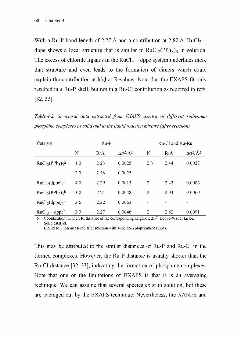
68 Chapter 4
With a Ru-P bond length of 2.27 Â and a contribution at 2.82 Â, RUCI3 +
dppe shows a local structure that is similar to RuCl2(PPfi3)3 in solution.
The excess of chloride ligands in the RUCI3 + dppe system underlines more
that structure and even leads to the formation of dimers which could
explain the contribution at higher R-values. Note that the EXAFS fit only
resulted in a Ru-P shell, but not in a Ru-Cl contribution as reported in refs.
[32,33].
Table 4-2. Structural data extracted from EXAFS spectra of different ruthenium
phosphine complexes as solid and in the liquid reaction mixture (after reaction)
Catalyst Ru-P Ru-Cl and Ru-Ru
N R/Â Aa2/Â2 N R/Â Aa2/Â2
RuCl2(PPh3)3a 1.0
2.0
2.23
2.38
0.0025
0.0025
2.3 2.44 0.0027
RuCl2(dppe)2a 4.0 2.29 0.0013 2 2.42 0.0006
RuCl2(PPh3)3b 3.0 2.24 0.0048 2 2.93 0.0060
RuCl2(dppe)2b 3.6 2.32 0.0063 - - -
RuCl3 + dppeb 3.9 2.27 0.0046 2 2.82 0.0091
N Coordination number; R: distance of the corresponding neighbor; Aa2: Debye-Waller factor.
a Solid catalyst.b
Liquid solution measured after reaction with 3-methoxypropylamine (mpa).
This may be attributed to the similar distances of Ru-P and Ru-Cl in the
formed complexes. However, the Ru-P distance is usually shorter than the
Ru-Cl distance [32, 33], indicating the formation of phosphine complexes.
Note that one of the limitations of EXAFS is that it is an averaging
technique. We can assume that several species exist in solution, but these
are averaged out by the EXAFS technique. Nevertheless, the XANES and

A Simple Route to Ruthenium-catalyzed Formylations 69
EXAFS data show that the structure of the in situ formed complex of the
RUCI3 + dppe mixture is similar to RuCl2(PPfi3)2 after reaction. In a next
step, it would be desirable to identify in more detail the hydrido species,
which is known to be easily formed in the presence of hydrogen [34, 35].
Finally, it seems likely that the extension of the in situ catalyst preparation
to other transition metals and other phosphines may provide catalysts with
even higher efficiency than those shown in this work. A systematic study
towards this aim could be rewarding.
4.5 Conclusions
The in situ generation of highly active catalysts from solid RUCI3 and a
suitable phosphine (dppe or PPI13) for the formylation of mpa from
hydrogen and carbon dioxide has been demonstrated by catalytic
measurements, in combination with X-ray absorption spectroscopy and
ICP-OES. The activity and the structure of the formed catalyst is similar to
RuCl2(PPfi3)3. The use of this simple method for catalyst preparation may
open new possibilities for high-throughput screening and lead to more
economical and greener formylation processes requiring only very low
amounts of an easily accessible catalyst.
4.6 References
[1] A. Behr, Angew. Chem. Int. Ed. Engl. 27 (1988) 661.
[2] W. Leitner, Angew. Chem. Int. Ed. Engl. 34 (1995) 2207.
[3] P. G. Jessop, T. Ikariya, R. Noyori, Chem. Rev. 95 (1995) 259.
[4] A. Baiker, Appl. Organomet. Chem. 14 (2000) 751.
[5] O. Kröcher, R. A. Koppel, A. Baiker, Chimia 51 (1997) 48.

70 Chapter 4
[6] P. G. Jessop, T. Ikariya, R. Noyori, Chem. Rev. 99 (1999) 475.
[7] S. Schreiner, J. Y. Yu, L. Vaska, Inorg. Chim. Acta 147 (1988) 139.
[8] O. Kröcher, R. A. Koppel, A. Baiker, Chem. Commun. 5 (1997) 453.
[9] P. G. Jessop, Y. Hsiao, T. Ikariya, R. Noyori, J. Am. Chem. Soc. 118
(1996)344.
[10] L. Schmid, A. Canonica, A. Baiker, Appl. Catal. A: Gen. 255 (2003)
23.
[11] L. Schmid, M. Rohr, A. Baiker, Chem. Commun. (1999) 2303.
[12] L. Schmid, M. S. Schneider, D. Engel, A. Baiker, Catal. Lett. 88
(2003) 105.
[13] G. Süss-Fink, M. Langenbahn, T. Jenke, J. Organomet. Chem. 368
(1989)103.
[14] P. G. Jessop, T. Ikariya, R. Noyori, Nature 368 (1994) 231.
[15] C. A. Thomas, R. J. Bonilla, Y. Huang, P. G. Jessop, Can. J. Chem.
79(2001)719.
[16] C.-C. Tai, J. Pitts, J. C. Linehan, A. D. Main, P. Munshi, P. G.
Jessop, Inorg. Chem. 41 (2002) 1606.
[17] Y. Kiso, K. Saeki, Japan. Kokai Tokkyo Koho (1977) 36617.
[18] J. Z. Zhang, Z. Li, H. Wang, C. Y. Wang, J. Mol. Catal. A: Chem.
112(1996)9.
[19] O. Kröcher, R. A. Koppel, A. Baiker, J. Mol. Catal. A: Chem. 140
(1999) 185.

A Simple Route to Ruthenium-catalyzed Formylations 71
[20] K. Okamoto, T. Takahashi, K. Kohdate, H. Kondoh, T. Yokoyama,
T. Ohta, J. Synchrotron Rad. 8 (2001) 689.
[21] T. Ressler, J. Synchrotron Rad. 5 (1998) 118.
[22] R. A. Sheldon, M. Wallau, I. W. C. E. Arends, U. Schuchardt, Ace.
Chem. Res. 31(1998)485.
[23
[24
[25
[26
[27
[28
[29
[30
[31
J.-D. Grunwaldt, A. Baiker, Phys. Chem. Chem. Phys. 7 (2005)
3526.
P. G. Jessop, W. Leitner, Chemical Synthesis Using Supercritical
Fluids, Wiley-VCH, Weinheim (1999).
S. G. Fiddy, J. Evans, T. Neisius, X. Z. Sun, Z. Jie, M. W. George,
Chem. Commun. 6 (2004) 676.
S. I. Zabinsky, J. J. Rehr, A. Ankudinov, R. C. Albers, M. J. Eller,
Phys. Rev. B. 52 (1995) 2995.
S. J. LaPlaca, J. A. Ibers, Inorg. Chem. 4 (1965) 778.
T. S. Lobana, R. Singh, E. R. T. Tiekink, J. Coord. Chem. 21 (1990)
225.
A. R. Chakravarty, F. A. Cotton, W. Schwotzer, Inorg. Chim. Acta
84(1984)179.
E. P. Perez, R. M. Carvalho, R. H. A. Santos, M. T. P. Gambardella,
B. S. Lima-Neto, Polyhedron 22 (2003) 3289.
M. R. M. Fontes, G. Oliva, L. A. C. Cordeiro, A. A. Batista, J.
Coord. Chem. 30 (1993) 125.

72 Chapter 4
[32] E. Lindner, S. Al-Gharabli, I. Warad, H. A. Mayer, S. Steinbrecher,
E. Plies, M. Seiler, H. Bertagnolli, Z. Anorg. Allg. Chem. 629 (2003)
161.
[33] O. Kröcher, R. A. Koppel, M. Fröba, A. Baiker, J. Catal. 178 (1998)
284.
[34] M. G. Basallote, J. Duran, Inorg. Chem. 38 (1999) 5067.
[35] B. R. James, A. Pacheco, S. J. Rettig, I. S. Thorburn, R. G. Ball, J.
A. Ibers, J. Mol. Catal. 41 (1987) 147.
Chapter
Formylation with Supercritical Carbon
Dioxide over RU/AI2O3 Modified by
Phosphines: Heterogeneous or
Homogeneous Catalysis?
5.1 Summary
The formylation of 3-methoxypropylamine with hydrogen and supercritical
carbon dioxide over ruthenium-based catalysts was studied. In this
solventless process, carbon dioxide acts both as a reactant and as a solvent.
Interestingly, Ru/Al203 modified by the phosphine 1,2-bis(diphenyl-
phosphino)ethane (dppe) showed a high formylation activity at 100%
selectivity, comparable to those of the homogeneous catalysts
RuCl2(dppe)2 and RuCl2(PPli3)3. Analysis of the reaction mixture using
ICP-OES and structural studies by in situ X-ray absorption spectroscopy
revealed that the presence of the phosphine modifier did not lead to the
modification of the Ru surface, but to the formation of a homogeneous
ruthenium catalyst.
5
74 Chapter 5
5.2 Introduction
A step toward "green" formylation of amines is the use of carbon dioxide
and hydrogen as formylation agents instead of toxic compounds such as
carbon monoxide and phosgene [1-5]. This approach provides the
opportunity to use supercritical carbon dioxide acting as both Ci -building
block and solvent (solvent-free process) [6-9]. A variety of ruthenium
complexes have been reported [10, 11] to be active and selective for such
formylation reactions, including RuCl2(PMe3)4 in the formylation of
hydrogen with carbon dioxide to formic acid [7], RuCl2(PPli3)3,
Ru3(CO)i2 [12] and RuCl2(dppe)2 [13] in the formylation of
dimethylamine, propylamine [14], and morpholine [15]. Among these
ruthenium-based complexes, RuCl2(dppe)2 was found to be superior with
respect to activity and stability [13, 14, 16].
A further step toward a "green" process is the application of heterogeneous
catalysts because of their intrinsic advantages concerning catalyst
separation, reuse and handling. An interesting approach is the
immobilization of the corresponding homogeneous complexes
functionalized by silyl ether groups in an inert silica matrix, as shown
previously for RuCl2X3 (X = Ph2P(CH2)2Si(OEt)3, Me2P(CH2)2Si(OEt)3)
[8, 17] and RuCl2(dppp)2 (dppp = Ph2P(CH2)3PPh2) [18]. However, the
preparation of these Ru-silica hybrid gels is rather demanding, and more
easy accessible heterogeneous catalysts would be desirable. A simpler
approach might involve the modification of a supported Ru-catalyst with a
suitable phosphine, which is the focus of this study. The modification of
metal catalysts by adsorbed auxiliaries (modifiers) has been successfully
applied to improve the catalytic properties of a variety of metals, as
covered in a recent review [19]. A related example is the use of phosphine

Formylation over Ru/Al203 Modified by Phosphines 75
modifiers in partial oxidation reactions on Pt/alumina catalysts [20]. This
prompted us to apply this strategy to the formylation using a 5 wt-%
Ru/Al203 catalyst modified with a phosphine (dppe or PPI13, see route 2,
Figure 1-2 in chapter 1, section 1-5). We show that these catalysts exhibit
good activity in the formylation of 3-methoxypropylamine at 100%
selectivity. Extensive in situ EXAFS studies using a specially designed
high-pressure cell revealed that the observed catalytic behavior has to be
attributed to a highly active homogeneous Ru complex formed from the
Ru/alumina catalyst during reaction.
5.3 Experimental
5.3.1 Catalyst Materials
The 5 wt-% Ru/Al203 catalyst (9001, escat 44, powder, prereduced) was
used as received from Engelhard. Note that the ruthenium catalyst was
partially oxidized, but we denote it as Ru/Al203. The 5 wt-% Ru/Al203
catalyst was modified with dppe in two different ways. On the one hand,
dppe was added before the reaction by reflux in THF during 2 h and dried
under high vacuum; on the other hand, it was simply added during the
reaction (section 5.3.2).
The homogeneous RuCl2(dppe)2 catalyst was synthesized according to the
method of Mason et al. [21]. A suspension of 1.00 g RuCl2(PPli3)3 in 20 ml
acetone was mixed with 0.85 g dppe under Ar atmosphere and fast stirring.
A yellow precipitate was observed after 2 min. It was separated with a
suction filter after 10 min of stirring at room temperature. The yellow
powder produced was washed with acetone and methanol and dried in
vacuum, and its structure was confirmed with lH-, 31P-NMR and elemental

76 Chapter 5
analysis; calculated (%) for C52H48Cl2P4Ru (968.8 g/mol): C 64.47, H
4.99, P 12.79, CI 7.32, Ru 10.43, found: C 64.30, H 5.19, P 12.94.
RuCl2(PPli3)3, tris(triphenylphosphine)ruthenium(II)dichloride (Fluka,
purum) was used as received after structural analysis by lH-, 31P-NMR and
elemental analysis; calculated (%) for C54H45Cl2P3Ru (958.8 g/mol): C
67.64, H 4.73, P 9.69, CI 7.39, Ru 10.54; found: C 67.36, H 4.84, P 9.72,
CI 7.56.
5.3.2 Catalytic Formylation of 3-Methoxypropylamine
The catalytic studies were performed using a 500 ml high-pressure stainless
steel autoclave (see chapter 2, section 2.1.1) with temperature control, a
rupture disk, and a dosing system for gases [22]. The chemicals 3-methoxy¬
propylamine (mpa, Fluka, >99%) and l,2-bis(diphenylphosphino)ethane
(dppe, Fluka, 98%) were used as received, liquid carbon dioxide (99.995%)
and hydrogen gas (99.999%) were supplied by Pangas.
In a typical procedure, mpa, dppe, and Ru/Al203 were poured into the
reactor before it was closed and flushed with hydrogen. The reactor was
filled with hydrogen (p ~ 60 bar). After the reactor temperature reached
100°C, the hydrogen pressure was adjusted to 80 bar, and 100 g carbon
dioxide was added. This resulted in a total pressure of about 200 bar. The
stirring rate was fixed at 300 min-1. After a certain reaction time, the
reactor was cooled down and depressurized by opening the outlet valve.
The reaction mixture was analyzed with a gas Chromatograph (HP-6890)
equipped with a HP-5 capillary column (30 m x 0.32 mm x 0.25 ixm) and a
flame ionization detector (FID). Product identification was achieved with a
gas Chromatograph (HP-6890) coupled to a mass spectrometer (HP-5973).
In a parametric study, the temperature and the amounts of catalyst, mpa,
Formylation over Ru/Al203 Modified by Phosphines 77
hydrogen and carbon dioxide were varied in order to find the optimal
reaction conditions.
5.3.3 Characterization of In Situ Formed Homogeneous Complex
Using ICP-OES
After reaction, selected samples were filtrated and centrifuged to quantify
the ruthenium and phosphorus content of the liquid phase with inductively
coupled plasma optical emission spectroscopy (performed by ALAB AG in
Urdorf, Switzerland).
5.3.4 Ex Situ and In Situ X-ray Absorption Spectroscopic Studies
The extended X-ray absorption fine structure (EXAFS) and X-ray
absorption near edge structure (XANES) experiments presented here were
mainly performed at the beamline XI, HASYLAB at DESY in Hamburg,
Germany. The storage ring typically operates at 4.45 GeV and a ring
current between 80 and 120 mA. A Si(311) double-crystal monochromator
was used, and higher harmonics were effectively removed by detuning the
crystals to 70% of the maximum intensity. Three ionization chambers filled
with Ar were used to record the intensity of the incident and the transmitted
X-rays. The samples were located between the first and second ionization
chamber, and a reference sample (RUCI3 pellet) was placed between the
second and the third ionization chamber. Some additional experiments
were performed at the Swiss-Norwegian beamline (SNBL) at the European
Synchrotron Radiation Facility (ESRF) in Grenoble, France. At SNBL, a
Si(lll) crystal was used as a channel-cut monochromator, and a double-
bounce gold-coated mirror system helped to reject the higher harmonics.
The three ionization chambers were filled with Ar, N2 or Kr in different
combinations (I0 Ar, It 30% Kr and 70% N2, Iref 30% Kr and 70% N2). At

78 Chapter 5
both beamlines (XI and SNBL), EXAFS spectra were taken under
stationary conditions in the step-scanning mode around the Ru K-edge
(22.117 keV) between 21.900 and 22.800 keV, with a RuCl3 pellet as a
reference. Fast QEXAFS scans were recorded in the continuous scanning
mode, usually between 22.065 and 22.665 keV (0.15 s/eV). The raw data
were energy-calibrated (Ru K-edge energy of the RUCI3 pellet: 22.120 keV
[23], first inflection point), background-corrected, and normalized with
WINXAS 3.0 software [24]. The EXAFS data was Fourier-transformed to
the kl-weighted functions in the interval k = 3-12.5Â_l and fitted to R-
space. Typical deviations for the coordination number were within ±0.5,
and those for the distance were within ±0.02 Â.
To identify the structure of the ruthenium complexes formed, the product
solution was investigated by EXAFS on liquid samples after reaction as
well. For this purpose, the special stainless steel EXAFS cell, described in
chapter 2, section 2.2.1, was used for transmission experiments. Because of
the low concentration of Ru in the product mixture (50- 100 ppm) the
EXAFS cell with the long path length of 4 cm was chosen.
After calibration with a sample of known absorption step u-d, the
concentration of the solution could also be determined independently of the
ICP-OES measurements.
In addition, in order to perform spectroscopic studies under reaction
conditions, the in situ batch reactor described in chapter 2, section 2.2.2
was used, since it allows investigation of the reaction volume at two
locations [25]. Both the solid catalyst sample at the bottom and the liquid
phase 10 mm above the bottom could be probed. For the experiments,
100 mg of 5 wt-% Ru/Al203 was loaded into the batch reactor cell, 3.0 ml
of mpa was added, and the reactor was closed. After cell alignment, normal

Formylation over Ru/Al203 Modified by Phosphines 79
EXAFS spectra of the solid catalyst and the solution were taken at room
temperature, while the solution was stirred with a magnetic stirrer.
Hydrogen (purity 99.999%) was added to a pressure of 70 bar, and 4 g of
liquid C02 was introduced with the help of a C02 compressor (NWA PM-
101) and a Rheonik mass flow controller (RHM015). While changes in the
solid material were monitored by QEXAFS, the mixture was heated to
120°C. Then the reaction mixture was cooled down to room temperature.
The treatment (addition of hydrogen and carbon dioxide and heating to
100°C) was repeated, but this time after adding 50 mg dppe.
5.4 Results
5.4.1 Modification of RU/AI2O3 with dppe and its Performance in the
Formylation of 3-Methoxypropylamine
Table 5-1 gives an overview of the catalytic results obtained during the
formylation under different reaction conditions. The dppe-modified
Ru/Al203 catalyst system showed good catalytic performance, whereas
runs without either catalyst or dppe (run 1-3) were unsuccessful. A highly
active catalyst was thus formed by modification of the Ru/Al203 surface
with dppe in a molar dppe:Ru ratio of 1:1. The addition of dppe before the
catalytic reaction under reflux in THF (premodification), or its addition
directly during the reaction itself led to similar catalytic performance.
Consequently, most of the experiments were carried out without pre¬
modification. Table 5-1 provides some information about the influence of
parameters like temperature, the amount of carbon dioxide, the initial
partial pressure of hydrogen, and the amounts of Ru/Al203 and dppe on the
conversion. As expected, the increase of the temperature led to a higher
reaction rate (run 4-6).
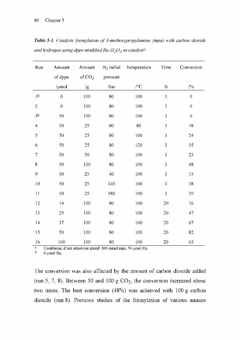
80 Chapter 5
Table 5-1. Catalytic formylation of 3-methoxypropylamine (mpa) with carbon dioxide
and hydrogen using dppe-modifiedRu/Al2Oß as catalyst0
Runi Amount
of dppe
Amount
ofC02
H2 initial
pressure
Temperature Time Conversion
/umol /g /bar /°C /h /%
lb 0 100 80 100 3 0
2 0 100 80 100 3 0
3b 50 100 80 100 3 0
4 50 25 80 80 3 18
5 50 25 80 100 3 24
6 50 25 80 120 3 35
7 50 50 80 100 3 23
8 50 100 80 100 3 48
9 50 25 40 100 3 15
10 50 25 140 100 3 38
11 50 25 180 100 3 39
12 14 100 80 100 20 16
13 25 100 80 100 20 47
14 37 100 80 100 20 67
15 50 100 80 100 20 82
16 100 100 80 100 20 63
a Conditions, if not otherwise stated: 100 mmol mpai, 50 |amol Ru.
b 0 |amol Ru.
The conversion was also affected by the amount of carbon dioxide added
(run 5, 7, 8). Between 50 and 100 g C02, the conversion increased about
two times. The best conversion (48%) was achieved with 100 g carbon
dioxide (run 8). Previous studies of the formylation of various amines

Formylation over Ru/Al203 Modified by Phosphines 81
[14, 15] under similar conditions showed that the reaction mixture is made
up of two distinguishable phases: A dense liquid-like phase containing
mainly the amine, the product formamide and water, and on top of that a
supercritical, more gas-like phase containing mainly hydrogen and the
carbon dioxide (note that the term supercritical is exactly defined only for
pure substances [26]). Increasing the initial hydrogen pressure between 40
and 140 bar, resulted in higher conversions (Table 5-1, run 5, 9 - 11). At
40 bar hydrogen pressure, 15% conversion was reached within 3 h, whereas
at 140 bar, 38% and at 180 bar, 39% conversion was achieved. The amount
of dppe added affected the reaction as well (Table 5-1, run 12-16).
Conversion increased with the addition of dppe up to 82%, the P/Ru-ratio
(mol/L Ru / mol/L P) in this optimal case was 2:1. When dppe was added
in a P/Ru-ratio of 4:1, the conversion decreased to 63%.
800
600
sz
400 OI-
D200
0
Figure 5-1. Comparison of the activity of the homogeneous complexes RuCE(dppe)2,
RuCÏ2(PPh3)3 with dppe-modified Ru/Al2Oß in 3-methoxypropylamine formylation.
Reaction conditions: 100 mmol mpa, 50 jumol Ru, 100 g CO2, 80 bar H2 initial partial
pressure, 3 h and 100°C.

82 Chapter 5
By way of comparison, related homogeneous ruthenium catalysts were
tested in the formylation reaction; results are shown in Figure 5-1. The
homogeneous complexes RuCl2(dppe)2 and RuCl2(PPli3)3 showed a
turnover frequency of 425 tr1 and 235 h-1, respectively, at 100%
selectivity. Dppe-modified Ru/Al203 showed a conversion of 48% under
the same reaction conditions. This conversion is higher than that observed
with the homogeneous catalyst RuCl2(PPli3)3, but lower than that observed
with RuCl2(dppe)2. The higher activity of RuCl2(dppe)2 compared with
RuCl2(PPfi3)3 is in line with earlier studies [14], where RuCl2(dppe)2 has
been found to be most active.
5.4.2 Identification of the Catalytically Active Species
Figure 5-2 shows the ex situ X-ray absorption spectra of the solid catalyst
under different conditions: 1) Ru/Al203 untreated, 2) Ru/Al203 treated
with dppe and amine before the reaction, and 3) dppe-modified Ru/Al203
after the reaction. A clear decrease in the whiteline at 22.12 keV is apparent
after step 3), which reveals that ruthenium constituent was partly reduced
during the reaction. No change in the EXAFS spectra was observed during
modification of the Ru/Al203 catalysts by treatment with amine and dppe
in advance. In the EXAFS region (Fourier-transformed data, not shown), a
clear change in the Ru-0 and the Ru-Ru backscattering was found.
However, ruthenium was not completely reduced.
To elucidate the role of possible corrosion of the Ru constituent and the
formation of active ruthenium complexes in solution under reaction
conditions in the presence of dppe, we performed appropriate tests that
allowed us to distinguish between heterogeneous and homogeneous
catalysis [27]. The reaction was stopped after a certain time, the solid

Formylation over Ru/Al203 Modified by Phosphines 83
catalyst was filtered off, and we inspected it in order to determine whether
the reaction could be continued in the filtered reaction mixture (Table 5-2).
Note that almost the same conversion was observed, irrespective of
whether the Ru/Al203 catalyst was filtered off after 3 h or whether it was
present during the whole reaction time. This implies that during the first 3 h
of the reaction, a highly active Ru-based homogeneous catalyst must have
been formed.
22 1 22 2 22 3
E/keV
22 4 22 5
Figure 5-2. XAFS spectra of 1) Ru/A^O^, compared to 2) dppe-modified Ru/A^O^
before reaction (pretreated with dppe and amine under reflux), and 3) dppe-modified
RU/AI2O3 after reaction.
In addition, the ruthenium and phosphorus contents in the liquid phase of
the samples were measured by ICP-OES. Table 5-3 gives an overview. The
ruthenium concentration in the liquid reaction mixture was about 50 ppm
(50 mg/kg, mass based) after 3 h (run 20) under standard reaction
conditions, as described above. The results show that after 20 h, 66 ppm
(0.689 mmol/L) ruthenium was dissolved in the liquid phase (run 21),
compared with 60 ppm (0.631 mmol/L) if the catalyst was filtered off after
3 h (run 22).
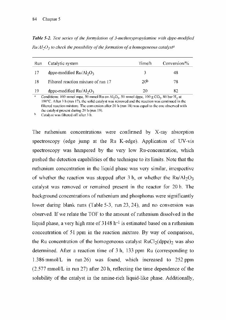
84 Chapter 5
Table 5-2. Test series of the formylation of 3-methoxypropylamine with dppe-modified
Ru/Al20ß to check the possibility oftheformation ofa homogeneous catalyst0
Run Catalytic system Time/h Conversion/%
17 dppe-modified Ru/Al203 3 48
18 Filtered reaction mixture of run 17 20b 78
19 dppe-modified Ru/Al203 20 82
a Conditions: 100 mmol mpa, 50 mmol Ru on A1203, 50 mmol dppe, 100 g C02, 80 bar H2 at
100°C. After 3 h (run 17), the solid catalyst was removed and the reaction was continued in the
filtered reaction mixture. The conversion after 20 h (run 18) was equal to the one observed with
the catalyst present during 20 h (run 19).b Catalyst was filtered off after 3 h.
The ruthenium concentrations were confirmed by X-ray absorption
spectroscopy (edge jump at the Ru K-edge). Application of UV-vis
spectroscopy was hampered by the very low Ru-concentration, which
pushed the detection capabilities of the technique to its limits. Note that the
ruthenium concentration in the liquid phase was very similar, irrespective
of whether the reaction was stopped after 3 h, or whether the Ru/Al203
catalyst was removed or remained present in the reactor for 20 h. The
background concentrations of ruthenium and phosphorus were significantly
lower during blank runs (Table 5-3, run 23, 24), and no conversion was
observed. If we relate the TOF to the amount of ruthenium dissolved in the
liquid phase, a very high rate of 3148 fr1 is estimated based on a ruthenium
concentration of 51 ppm in the reaction mixture. By way of comparison,
the Ru concentration of the homogeneous catalyst RuCl2(dppe)2 was also
determined. After a reaction time of 3 h, 133 ppm Ru (corresponding to
1.386 mmol/L in run 26) was found, which increased to 252 ppm
(2.577 mmol/L in run 27) after 20 h, reflecting the time dependence of the
solubility of the catalyst in the amine-rich liquid-like phase. Additionally,

Formylation over Ru/Al203 Modified by Phosphines 85
in the case of the homogeneous catalyst RuCl2(PPli3)3, a concentration of
385 ppm Ru and 375 ppm P (according to a P/Ru ratio of 3) was detected
(run 25). Note that the concentration of Ru was very small, but sufficient to
catalyze the formylation of mpa.
Table 5-3. Solubility of the in situformed catalystfrom Ru/Al2Oß and dppe in the liquid
phase, compared to RuCE(PPh3)3 andRuCE(dppe)2
Run Catalyst Reaction dataa Dissolved in reac
Ru P
;tion mixture
Time Conv. TOFb P/Ru
/h /% /h-1 /ppm /ppm /(mol/mol)
20 dppe-modified
Ru/Al203
3 48 3148 50.5 251 16.2
21 dppe-modified
Ru/Al203
20 82 559 66.4 256 12.6
22 dppe-modified
Ru/Al203
20 78 585 60.6 294 15.8
23c Blank test 3 0 0 0.60 21.8 118
24d dppe 3 0 0 1.89 268 463
25 RuCl2(PPh3)3 3 36 315 385 375 3
26 RuCl2(dppe)2 3 64 425 133 173 4.2
27 RuCl2(dppe)2 20 91 91 252 319 4.1
Conditions: 50 |amol Ru, 100 mmol mpa, 100 g C02, 80 bar H2 partial pressure, 100°C.
TOF based on Ru dissolved in reaction mixture.
0 mol Ru, 0 mol dppe.0 mol Ru, 50 |amol dppe.

86 Chapter 5
5.4.3 Spectroscopic Study of the In Situ Formation of the
Homogeneous Ruthenium Catalyst
To understand the formation of the homogeneous catalyst, the changes in
the solid Ru/Al203 catalyst and in the liquid phase were investigated. For
this purpose, the specially designed batch reactor cell - described in
chapter 2, section 2.2.2-was used. It allowed in situ EXAFS measure¬
ments both at the bottom (solid phase) and in the center (liquid) of the
batch reactor [25]. In a first step, the catalyst was investigated in the
presence of mpa, hydrogen, and carbon dioxide. The results are shown in
Figure 5-3. Figure 5-3a shows the treatment of the catalyst in the reaction
mixture without dppe. Figure 5-3b depicts the spectra taken during the
reaction in the presence of dppe.
22 2 22 3
E/keV
22 1 22 2 22 3 22 4 22 5
E/keV
Figure 5-3. a) Reduction of Ru/A^O^, monitored in situ by X-ray absorption
spectroscopy, solidphase 1) before reaction at 40°C as reference, and at 120°C after 2)
0 min, 3) 30 min, 4) 60 min, 5) 150 min reaction time, b) In situ monitoring during
reaction over Ru/A^O^, solidphase 1) before reaction at 40°C as reference, and with
dppe at 100°C after 2) 150 min, 3) 160 min, 4) 250 min. Conditions: 10 ml batch
reactor cell, 3 ml mpa, 70 bar H2, totalpressure 120 bar, rest CO2-
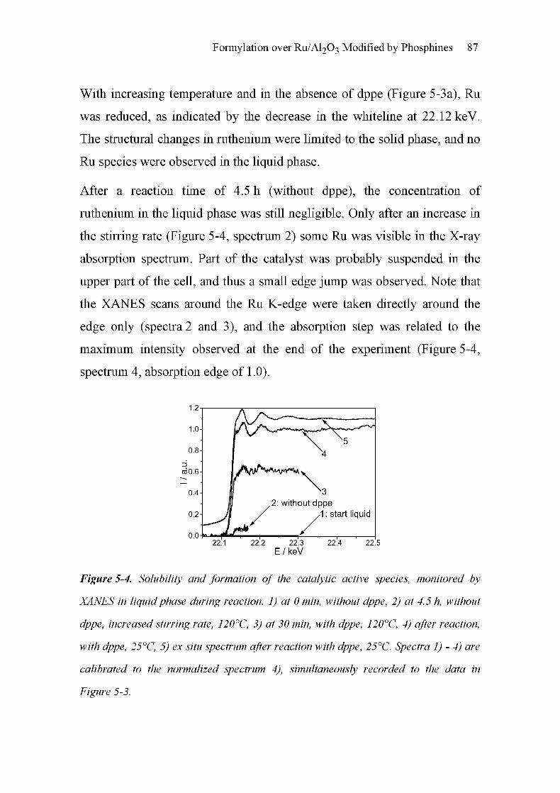
Formylation over Ru/Al203 Modified by Phosphines 87
With increasing temperature and in the absence of dppe (Figure 5-3a), Ru
was reduced, as indicated by the decrease in the whiteline at 22.12 keV.
The structural changes in ruthenium were limited to the solid phase, and no
Ru species were observed in the liquid phase.
After a reaction time of 4.5 h (without dppe), the concentration of
ruthenium in the liquid phase was still negligible. Only after an increase in
the stirring rate (Figure 5-4, spectrum 2) some Ru was visible in the X-ray
absorption spectrum. Part of the catalyst was probably suspended in the
upper part of the cell, and thus a small edge jump was observed. Note that
the XANES scans around the Ru K-edge were taken directly around the
edge only (spectra 2 and 3), and the absorption step was related to the
maximum intensity observed at the end of the experiment (Figure 5-4,
spectrum 4, absorption edge of 1.0).
E/keV
Figure 5-4. Solubility and formation of the catalytic active species, monitored by
XANES in liquidphase during reaction. 1) at 0 min, without dppe, 2) at 4.5 h, without
dppe, increased stirring rate, 120°C, 3) at 30 min, with dppe, 120°C, 4) after reaction,
with dppe, 25°C, 5) ex situ spectrum after reaction with dppe, 25°C. Spectra 1) - 4) are
calibrated to the normalized spectrum 4), simultaneously recorded to the data in
Figure 5-3.
88 Chapter 5
Therefore, during this first step no catalyst was dissolved in the liquid-like
amine-rich phase. However, as soon as dppe was added, an abrupt increase
in the Ru concentration and a further increase during heating was observed
(Figure 5-4, traces 3 and 4). During this step, almost no changes in the solid
Ru-catalyst (Figure 5-3B) could be noticed. The in situ formation of the
active species in the liquid-like amine-rich phase as a consequence of
adding dppe (Figure 5-4) can be related to the tendency of this ligand to
corrode the ruthenium and form Ru complexes. Supporting this view was
the fact that no catalytic activity was observed in the absence of dppe, and
no significant amount of Ru was found in the liquid solution with ICP-OES
(Table 5-3). Note that the in situ spectrum after the reaction (Figure 5-4,
spectrum 4) and the ex situ spectrum after the reaction (Figure 5-4, trace 5)
look quite similar. No substantial change could be observed while cooling
and depressurizing occurred.
5.4.4 Structural Identification of the Homogeneous Ruthenium
Complex
To gain insight into the structure of the active species formed in situ, ex situ
XANES and EXAFS spectra were recorded. Because of the low
concentration of 50-100 ppm in the reaction mixture, the liquid cell with
4 cm path length was used, as described in chapter 2, section 2.2.1. The top
of the cell was open in order to eliminate possible gas bubbles in the highly
viscous product mixture, and Kapton foils were used as X-ray transparent
windows on both sides of the liquid cell to keep the liquid within the beam.
Figure 5-5 compares the XANES region of the dppe-modified Ru/Al203
catalyst in the liquid product mixture with the homogeneous catalyst
RuCl2(dppe)2 in the liquid phase and as a solid (see corresponding catalytic

Formylation over Ru/Al203 Modified by Phosphines 89
results in Table 5-1). For structural identification, RuCl2(PPli3)3 in the
liquid reaction mixture was also investigated. The analytical results
indicate that the structure of the catalyst formed in situ from Ru/Al203 and
dppe is similar to the structure of RuCl2(dppe)2 under reaction conditions,
whereas the structure of the solid RuCl2(dppe)2 seems to be different,
probably as a consequence of the replacement of the chloride by hydrogen
and by the amine under reaction conditions.
— Ru/Al203 + dppe- RuCI2(dppe)2- RuCI2(PPh3)3— RuCI2(dppe)2, solid
10 22 12 22 14 22 16 22 18 22 20
E/keV
Figure 5-5. X-ray absorption near edge structure at the Ru K-edge of RuCE(dppe)2,
liquid product mixture (dotted black line), dppe-modified Ru/Al2Oß, liquid product
mixture (solid black line), RuCE(dppe)2, solid complex (dotted gray line), and
RuCÏ2(PPh3)3, liquid product mixture (solid gray line). Reference spectrum: solid
RuCÏ2(dppe)2-
Note that a change in the XANES region is also caused by the change in
multiple scattering paths, which, in addition, affect the near edge structure
[28, 29]. The variation of the XANES region of RuCl2(PPh3)3 indicates
that the structure of the catalyst formed in situ from Ru/Al203 and dppe
resembles more closely the structure of RuCl2(dppe)2 than that of
RuCl2(PPli3)3. Only a slight shift in the Ru K-edge is found, suggesting
that the oxidation states of the two complexes are similar [23].

90 Chapter 5
13
nj 0 0030-
^g 0 0025-
sz
.3> 0 0020-CD
-^ 0 0015-
-S 0 0010-13
D) 0 0005-
,_0 0000-
0 12 3 4 5
R/A
Figure 5-6. Comparison of the Fourier-transformed EXAFS spectra (k1 weighted) at
the Ru K-edge of RuCE(dppe)2 in reaction mixture from reaction with mpa (dotted
black line), dppe-modified Ru/A^O^ in reaction mixture (solid black line),
RuCE(dppe)2, solid phase (dotted gray line) and RuCEfPPhj)^, in reaction mixture
(solid gray line).
Figure 5-6 shows the corresponding ki-weighted Fourier-transformed
extended X-ray absorption fine structure (EXAFS) spectra. As in the case
of the near edge spectra, significant differences of the as-prepared solid
catalysts RuCl2(PPfi3)3 and RuCl2(dppe)2 and the corresponding Ru
complexes after reaction (liquid product mixture) are evident. The
backscattering is lower for both Ru-Cl and Ru-P, and the peak is shifted to
lower R-values (spectra not corrected for the phase shift). The spectra of
the catalysts exhibit backscattering peaks at 1.8 and 2.5 Â for all catalysts.
Whereas RuCl2(dppe)2 in reaction mixture and dppe-modified Ru/Al203
show similar backscattering from the nearest neighbor atoms, the solid
RuCl2(dppe)2 exhibits a large peak at 1.8 Â and only a very small one at
2.5 Â. The corresponding spectrum of RuCl2(PPfi3)3 is quite different
(Figure 5-6).

Formylation over Ru/Al203 Modified by Phosphines 91
_3
cc0 06-
, v
(1
ci> 0 04-
±.
m
ni 0 02-
5
'v 0 00-
CD-0 02-
-1-^
ni-0 04-
CD
2-0 06-
HLL
0
R/A R/A
Figure 5-7. Fourier-transformed and k1-weighted Ru K-edge EXAFS spectra (k^xfi))
of a) dppe-modifed Ru/A^O^ (20 h) and b) RuCE(dppe)2 after reaction: radial
distributionfunction together with the imaginary part, measured data (solid line), fitted
data (dotted line).
The Fourier-transformed spectra were fitted with Ru-Cl and Ru-P shells
calculated by FEFF 6.0 [30]; the results are listed in Table 5-4. Some of the
experimental and fitted data are compared in Figure 5-7. The structural data
obtained for the solid RuCl2(PPfi3)3 (entry 1 of Table 5-4) are in good
accordance with the literature [31]. For the solid homogeneous catalyst,
three different Ru-P bond lengths, 2.23 Â, 2.37 Â, and 2.41 Â were
reported. Only two Ru-P distances (2.23 Â and 2.38 Â, Table 5-4) could be
distinguished with EXAFS, and only one Ru-Cl bond length was detected
at 2.44 Â by EXAFS, a consequence of the limitations of the method used
in our studies. While the typical uncertainty is estimated to be ±0.02 Â for
the distance and about ±0.5 for the coordination number, the superposition
of two shells of the same backscatterer with similar distances, in particular,
could not be resolved satisfactorily. The results from the EXAFS spectra of
solid RuCl2(dppe)2 show that the different structure is appropriately
represented. Both Ru-P and Ru-Cl distances are found. The bond length of
Ru-Cl (2.42 À) in the solid RuCl2(dppe)2, calculated from the EXAFS fit,

92 Chapter 5
is in the range (2.436 Â) of the value published in literature [32]. In
addition, we found only one averaged Ru-P bond, as opposed to the two
different Ru-P bonds (2.389 À and 2.369 À) reported.
Table 5-4. Structural data extracted from EXAFS spectra of different ruthenium
phosphine complexes as solid and in liquidphase. Ru concentration in the liquidphase
~50 100 ppm, N: coordination number, R: distance of the corresponding neighbor,
Ao2: Debye-Wallerfactor
Catalyst Ru-P
N
Ru-Cl
R/Â Aa2/Â2
Residuald
N R/Â Aa2/Â2
RuCl2(PPh3)3a 1.0
2.0
2.23
2.38
0.0025
0.0025
2.3 2.44 0.0027 1.4
RuCl2(dppe)2a 4 2.29 0.0013 2 2.42 0.0006 2.0
RuCl2(PPh3)3b 4.1 2.22 0.0044 2 2.93 0.0060 7.2
RuCl2(dppe)2b 3.6 2.32 0.0063 - - 9.4
dppe-modified 3.3 2.35 0.0060 - - 3.2
Ru/Al203a Solid catalyst.b
Liquid solution measured after reaction with mpa.c Additional shell: Ru-N or Ru-O: N = 0.8, R = 2.07 Â, Aa2 = 0.006.
dQuality of the fit according to ref [24].
Significant structural changes were detected for the complexes formed
during the formylation reaction of mpa. After the use of RuCl2(PPfi3)3 in
the reaction, a Ru-P bond length of 2.22 Â, as well as an additional
contribution that could be fitted with a Ru-Ru distance at 2.93 Â, were
found, corresponding to the two peaks observed in Figure 5-6. This shows
that there are only slight changes in the Ru-P neighbors in liquid (after
reaction) or solid phase, but the Ru-Cl coordination changes. All bond

Formylation over Ru/Al203 Modified by Phosphines 93
lengths of the complexes RuCl2(dppm)2 [33], RuCl2(dppe)2 [32],
RuCl2(dppp)2 [34], RuBrCl(dppe)2 [35], and RuClH2(dppp)2PF6 [36]
reported in the literature are between 2.340 Â and 2.441 Â, depending on
the ligand used. Ru-Cl bond lengths range from 2.407 Â to 2.436 Â. In the
liquid phase, the bond length of Ru-P in RuCl2(dppe)2, 2.32 Â, is in the
expected range (the decrease may result from additional oxygen/nitrogen
neighbors in the complex), but no Ru-Cl bond is indicated in the spectra.
Thus, a change of the structure of RuCl2(dppe)2 in the liquid phase is
observed during the reaction. There are two plausible explanations for this
observation: The Cl-atoms could have been replaced by hydrogen to form a
hydrido complex [37-39], or a partial amino (or hydroxo-) complex was
formed, with hydrogen and mpa present in the liquid phase. Another reason
might be the similar Ru-P and Ru-Cl distances in the complexes formed.
However, the Ru-P distance is usually shorter than the Ru-Cl distance (see
references above and [40, 41]). Note also, that the catalyst was investigated
after air exposure. Finally, EXAFS analysis as an averaging technique has
its limitations when several species are involved.
The reaction mixture containing dppe-modified Ru/Al203 exhibited a Ru-P
bond length of 2.35 Â. This shows that a homogeneous Ru-dppe based
catalyst forms, as could already be concluded from the near edge region
and the Fourier-transformed EXAFS spectra. As expected, no Ru-Cl is
observed. The structure of this catalyst formed in situ seems to resemble
that of the observed RuCl2(dppe)2 in the liquid phase, but amino or oxygen
neighbors were also found in the first shell of the dppe-modified Ru/Al203
system. The EXAFS fit of the spectrum improved significantly when
nitrogen/oxygen neighbors (being neighbors in the periodic table, the two
atoms have similar backscattering amplitudes) were used additionally. The

94 Chapter 5
formation of such a complex is reasonable because the catalyst is dissolved
in the amine-rich phase during reaction.
5.5 Discussion
Ru/Al203 modified by dppe was found to be highly active for the
formylation of 3-methoxypropylamine (mpa), in conjunction with carbon
dioxide and hydrogen. The catalyst shows good activity and 100%
selectivity, comparable to the performance of the homogeneous ruthenium-
based phosphine complexes RuCl2((PCH3)3)4 and RuCl2(dppe)2. The
study indicates that the formylation of amines with hydrogen and carbon
dioxide can be extended to amines containing an ether group.
The reaction rates for mpa in terms of the TOF are comparable to or better
than those achieved with other primary amines, such as propylamine in the
presence of RuCl2(P(CH3)3)4 with 52 Ir1 [11]. Turnover frequencies of
secondary amines like diethylamine are between 440 h-l [3] and
360000 h"1 [13], depending on the catalyst used and the experimental
conditions.
Carbon dioxide acts as both reactant and solvent. C02 is not present as a
single supercritical phase, but exists in two phases, an amine-rich C02
phase with H2 dissolved, and a C02/H2 phase [14]. The volume of the
amine-rich C02 phase with dissolved H2 increases with the amount of
carbon dioxide in the system. Higher partial pressure of hydrogen affects
the dissolved amount of H2 in the amine-rich C02 phase and results -
together with the higher density - in a better mixing of the reactants in the
amine-rich C02 phase and, ultimately, in better conversion and TOF.
Interestingly, it was found that dppe-modified Ru/Al203 showed good
catalytic performance in the formation of 3-methoxypropylformamide,
Formylation over Ru/Al203 Modified by Phosphines 95
similar to the homogeneous catalysts RuCl2(dppe)2 and RuCl2(PPli3)3.
This behavior can be traced to the formation of active free Ru complexes as
a result of the interaction of the supported Ru particles with the strongly
complexing phosphine (dppe). This interaction leads to some corrosion of
the Ru particles.
The formation of a soluble complex during reaction could be proven in
different ways. On the one hand, X-ray absorption spectroscopy and ICP-
OES showed the presence of dissolved Ru in the product mixture. On the
other hand, the reaction could be resumed if the solid material was filtered
off after a certain reaction time (Table 5-2). Only a small fraction of the
ruthenium is dissolved, resulting in a concentration of 50-100 ppm in the
product mixture. This shows that the homogeneous Ru-based catalyst
formed is highly active (TOF based on the amount of dissolved Ru is about
3100 h-l, Table 5-3, run 20).
The formation of the ruthenium complex, which is acting as homogeneous
catalyst, could be monitored in situ by X-ray absorption spectroscopy. In
principle, there are only a few techniques, such as EXAFS spectroscopy,
UV-vis spectroscopy, NMR spectroscopy, and infrared spectroscopy that
render such studies feasible [42-46]. Because of the low concentration of
the homogeneous catalyst, structural studies using UV-vis were not
successful. The concentration of the target species was also too low for
NMR and IR spectroscopy. On the other hand, owing to the good
penetration capability of X-rays at 20 keV, EXAFS studies in the
transmission mode could be accomplished. The advantage of X-ray
absorption spectroscopy lies in the fact that the concentration and the
structure of the Ru species can be determined element-specifically and
under reaction conditions. Such studies are rarely done under such harsh

96 Chapter 5
conditions (150 bar, 120°C) as applied here and have only recently been
reported for solid [47] and homogeneous catalysts [48, 49]. In our case, we
found that the X-ray absorption technique, combined with an appropriately
high-pressure cell, allowed the simultaneous monitoring of the solid
catalyst at the bottom, and identification of the in situ formed complex in
the liquid phase in the upper part of the reactor.
During reaction, the ruthenium constituent in the solid catalyst is reduced.
However, ruthenium can only be found in the liquid phase if dppe is added
to the system. This indicates corrosion of the ruthenium particles in the
presence of hydrogen and dppe. Presumably it is the structure of the dppe
ligand helps in forming a highly stable chelate complex, favoring the
corrosion of the Ru and thus the in situ formation of the Ru complex.
Such an in situ formation of a homogeneous catalyst from a supported
metal catalyst has only rarely been reported. Köhler et al. recently
described the in situ formation of a Pd catalyst in Heck reactions [50]. In
this case, ligands/reactants in the solution led to the formation of an active
homogeneous catalyst. This example emphasizes the necessity for
appropriate in situ spectroscopic tools to help decide between
homogeneous complexes and surface modification on metal particles as
active species for catalysis.
The amount of dissolved ruthenium in the liquid phase was quantified by
ICP-OES and confirmed by XAS. The concentration of ruthenium was very
low, in the range of 50-100 ppm, and no redeposition as reported in ref.
[50] was observed. The TOF (3148 fr1) related to the dissolved ruthenium
species turned out to be significantly higher than the TOF (324 Ir1) based
on the total amount of ruthenium present in the reactor. We can conclude
that the ruthenium species formed in situ has a higher intrinsic activity than

Formylation over Ru/Al203 Modified by Phosphines 97
the homogeneous catalyst RuCl2(dppe)2. The reason for the better activity
may be found in the different structures of dissolved RuCl2(dppe)2 and the
species formed in situ from Ru/Al203 and dppe. Furthermore, the solubility
of RuCl2(dppe)2 in the reaction mixture may affect its catalytic
performance.
Structural analysis by EXAFS spectroscopy of the Ru complex formed
indicates that a Ru(dppe)2X2 catalyst is formed that may contain either
additional hydrido- or amino/hydroxo-ligands. The formation of a hydrido
complex was previously indicated in other studies [37-39, 51], and the
mechanism for the Ru-catalyzed formylation of amines proposed by Jessop
et al. [11] can be further confirmed. Based on these findings, we can
assume that a hydrido complex is probably formed from Ru/Al203 and
dppe in the liquid phase under reaction conditions. C02 is activated by
insertion into the metal-hydrogen bonding of the hydrido complex. In the
presence of mpa, the complex keeps reacting to form the product
3-methoxypropylformamide, and water is formed as a by-product.
The present study shows that the modification of supported transition-metal
catalysts by a phosphine may corrode the metal and result in free metal
phosphine complexes, disguising the intrinsic catalytic properties of the
modified supported metal catalyst. Similar behavior has also been observed
when another phosphine, triphenylphosphine, was applied. Thus it seems to
be of paramount importance to test for this possibility when supported
metal catalysts are applied in conjunction with phosphines.

98 Chapter 5
5.6 Conclusions
Modification of Ru/Al203 by the addition of a phosphine (dppe) has been
shown to result in homogeneous Ru catalysts that are highly active in the
formylation of 3-methoxypropylamine with carbon dioxide and hydrogen.
The catalytically active species were not the phosphine modified ruthenium
particles, but rather a homogeneous chlorine-free Ru-dppe complex that
formed under reaction conditions. The presence of dppe led to the
dissolution (corrosion) of ruthenium and probably to the formation of a
highly active homogeneous Ru(dppe)2X2 complex, which was sufficiently
active to achieve high conversion even at very small concentrations
(50 ppm Ru in reaction mixture).
X-ray absorption spectroscopy proved to be a valuable technique for
identifying the role of solid and liquid Ru species in the catalytic reaction.
The formation of the homogeneous catalyst could be monitored under
reaction conditions, and the structural identification of the homogeneous
Ru-dppe complex by transmission EXAFS was feasible down to a
concentration of 100 ppm and less in the product mixture.
5.7 References
[1] M. Halmann, Chemical Fixation of Carbon Dioxide: Methods for
Recycling CO2 into Useful Products, CRC Press, Boca Raton,
Florida (1993).
[2] W. Leitner, Angew. Chem. Int. Ed. Engl. 34 (1995) 2207.
[3] P. G. Jessop, T. Ikariya, R. Noyori, Chem. Rev. 95 (1995) 259.
[4] M. Aresta, E. Quaranta, Chemtech (1997) 32.
[5] A. Baiker, Appl. Organomet. Chem. 14 (2000) 751.
Formylation over Ru/Al203 Modified by Phosphines 99
6] A. Behr, Angew. Chem. Int. Ed. Engl. 27 (1988) 661.
7] P. G. Jessop, T. Ikariya, R. Noyori, Nature 368 (1994) 231.
8] O. Kröcher, R. A. Koppel, A. Baiker, Chimia 51 (1997) 48.
9] P. G. Jessop, W. Leitner, Chemical Synthesis Using Supercritical
Fluids, Wiley-VCH, Weinheim (1999).
10] P. G. Jessop, Y. Hsiao, T. Ikariya, R. Noyori, J. Am. Chem. Soc. 116
(1994)8851.
11] P. G. Jessop, Y. Hsiao, T. Ikariya, R. Noyori, J. Am. Chem. Soc. 118
(1996)344.
12] S. Schreiner, J. Y. Yu, L. Vaska, Inorg. Chim. Acta 147 (1988) 139.
13] O. Kröcher, R. A. Koppel, A. Baiker, Chem. Commun. 5 (1997) 453.
14] L. Schmid, A. Canonica, A. Baiker, Appl. Catal. A: Gen. 255 (2003)
23.
15] L. Schmid, M. S. Schneider, D. Engel, A. Baiker, Catal. Lett. 88
(2003) 105.
16] C.-C. Tai, J. Pitts, J. C. Linehan, A. D. Main, P. Munshi, P. G.
Jessop, Inorg. Chem. 41 (2002) 1606.
17] O. Kröcher, R. A. Koppel, A. Baiker, J. Chem. Soc, Chem.
Commun. (1996) 1497.
18] L. Schmid, M. Rohr, A. Baiker, Chem. Commun. (1999) 2303.
19] T. Mallat, A. Baiker, Appl. Catal. A: Gen. 200 (2000) 3.
20] T. Mallat, C. Brönnimann, A. Baiker, Appl. Catal. A: Gen. 149
(1997)103.

100 Chapter 5
[21
[22
[23
[24
[25
[26
[27
[28
[29
[30
[31
[32
[33
[34
R. Mason, D. W. Meek, G. R. Scollary, Inorg. Chimia Acta 16
(1976) LU.
O. Kröcher, R. A. Koppel, A. Baiker, J. Mol. Catal. A: Chem. 140
(1999) 185.
K. Okamoto, T. Takahashi, K. Kohdate, H. Kondoh, T. Yokoyama,
T. Ohta, J. Synchrotron Rad. 8 (2001) 689.
T. Ressler, J. Synchrotron Rad. 5 (1998) 118.
J.-D. Grunwaldt, M. Ramin, M. Rohr, A. Michailovski, G. R. Patzke,
A. Baiker, Rev. Sei. Instrum. 76 (2005) 054104.
R. Wandeler, N. Künzle, M. S. Schneider, T. Mallat, A. Baiker, J.
Catal. 200 (2000) 377.
R. A. Sheldon, M. Wallau, I. W. C. E. Arends, U. Schuchardt, Ace.
Chem. Res. 31(1998)485.
O. Sipr, G. Dalba, F. Rocca, Phys. Rev. B. 69 (2004) 134201.
D. Bazin, J. J. Rehr, J. Phys. Chem. B 107 (2003) 12398.
S. I. Zabinsky, J. J. Rehr, A. Ankudinov, R. C. Albers, M. J. Eller,
Phys. Rev. B. 52 (1995) 2995.
S. J. LaPlaca, J. A. Ibers, Inorg. Chem. 4 (1965) 778.
T. S. Lobana, R. Singh, E. R. T. Tiekink, J. Coord. Chem. 21 (1990)
225.
A. R. Chakravarty, F. A. Cotton, W. Schwotzer, Inorg. Chim. Acta
84(1984)179.
M. R. M. Fontes, G. Oliva, L. A. C. Cordeiro, A. A. Batista, J.
Coord. Chem. 30 (1993) 125.

[35
[36
[37
[38
[39
[40
[41
[42
[43
Formylation over Ru/Al203 Modified by Phosphines 101
E. P. Perez, R. M. Carvalho, R. H. A. Santos, M. T. P. Gambardella,
B. S. Lima-Neto, Polyhedron 22 (2003) 3289.
B. Chin, A. J. Lough, R. H. Morris, C. T. Schweitzer, C. D'Agostino,
Inorg. Chem. 33 (1994) 6278.
M. K. Whittlesey, R. N. Perutz, M. H. Moore, Organometallics 15
(1996)5166.
M. G. Basallote, J. Duran, Inorg. Chem. 38 (1999) 5067.
K. A. Lenero, M. Kranenburg, Inorg. Chem. 42 (2003) 2859.
E. Lindner, S. Al-Gharabli, I. Warad, H. A. Mayer, S. Steinbrecher,
E. Plies, M. Seiler, H. Bertagnolli, Z. Anorg. Allg. Chem. 629 (2003)
161.
O. Kröcher, R. A. Koppel, M. Fröba, A. Baiker, J. Catal. 178 (1998)
284.
M. Hunger, J. W. Weitkamp, Angew. Chem. Int. Ed. Engl. 40 (2001)
2954.
D. Bazin, H. Dexpert, J. Lynch, X-ray Absorption Fine Structure for
Catalysts and Surfaces, World Scientific, Singapore 2 (1996).
[44] G. Sankar, J. M. Thomas, Topics Catal. 8 (1999) 1.
[45] J.-D. Grunwaldt, B. S. Clausen, Topics Catal. 18 (2002) 37.
[46] J.-D. Grunwaldt, R. Wandeler, A. Baiker, Catal. Rev. -Sei. Eng. 45
(2003)1.
[47] J.-D. Grunwaldt, M. Caravati, M. Ramin, A. Baiker, Catal. Lett. 90
(2003)221.

102 Chapter 5
[48] S. L. Wallen, D. M. Pfund, J. L. Fulton, C. R. Yonker, M. Newville,
Y. Ma, Rev. Sei. Instrum. 67 (1996) 2843.
[49] S. G. Fiddy, J. Evans, T. Neisius, X. Z. Sun, Z. Jie, M. W. George,
Chem. Commun. 6 (2004) 676.
[50] R. G. Heidenreich, J. G. E. Krauter, J. Pietsch, K. Köhler, J. Mol.
Catal. A: Chem. 182-183 (2002) 499.
[51] L. Costella, A. Del Zotto, A. Mezzetti, E. Zangrando, P. Rigo, J.
Chem. Soc. Dalton Trans. (1993) 3001.

Chapter
Solvent-free Ruthenium-catalyzed Vinyl
Carbamate Synthesis from Phenylacetylene
and Diethylamine in Supercritical
Carbon Dioxide
6.1 Summary
As shown in the previous chapters, formylation reactions of amines with
hydrogen and carbon dioxide in the presence of ruthenium catalysts exhibit
a promising route of using carbon dioxide as a reactant and as a solvent. In
addition, other reactions - for example the synthesis of vinyl carbamate
from phenylacetylene, diethylamine, and carbon dioxide - show the
immense potential of using C02 as a raw material. This is the subject of the
present chapter. An environmentally friendly route of vinyl carbamate
synthesis, which is not only based on carbon dioxide as substrate, but also
on using supercritical carbon dioxide as the solvent is described. The
results show that the new method also provides enhanced reaction rates
compared to organic solvent-based systems.
6

104 Chapter 6
6.2 Introduction
The discovery that metal vinylidene complexes are readily available via the
reaction of late transition metal complexes with terminal alkynes spawned
a new field of catalytic chemistry utilizing this functionality [1]. Among
these transformations, the ruthenium catalyzed synthesis of vinyl
carbamates from carbon dioxide, secondary amines, and terminal
acetylenes has proven particularly interesting (Scheme 6-1) [2]. Vinyl
carbamates are versatile synthetic intermediates used in the pharmaceutical
and agrochemical industries [3]. In the past, all preparative routes to this
class of compounds have involved the highly toxic chemical phosgene [4].
o
Et2N^(OHC= CHPh
(1a) (E)
Ph-C = CH+HNEt +scCO, + (1b) (z)
O
EtN^ //CH2
Ph
C
(2)
CI
[Ru] = RuCI, xH20 PyvRiTPy Ru(C6H6)(PMe,)CI2
py'^py
(3) (4) (5)
Scheme 6-1. Vinyl carbamate synthesis from phenylacetylene, diethylamine and
supercritical carbon dioxide with ruthenium catalysts [Ru].
In the late 80's, Dixneuf et al. reported the homogeneous ruthenium(II)-
catalyzed synthesis of vinyl carbamates from secondary amines, a terminal
alkyne and carbon dioxide in organic solvents, effectively replacing
phosgene with non-toxic carbon dioxide [5]. The high natural abundance

Solvent-free Ru-catalyzed Vinyl Carbamate Synthesis 105
and ease of handling of carbon dioxide has prompted considerable interest
in its utilization in chemical processes [6-8]. Recent developments in this
field demonstrate that carbon dioxide is a useful reactant which can
simultaneously be used as a reaction medium [9-11]. As shown in the
previous chapters, C02 as a raw material is successfully used in the
formylation of amines, such as 3-methoxypropylamine [12, 13],
morpholine [14, 15], or diethylamine [16]. In these reactions, ruthenium
complexes were investigated regarding to their catalytic activity.
Specifically, RuCl2(dppe)2 as a homogeneous catalyst, in situ generated
catalysts from RUCI3 and phosphines (chapter 4) or from Ru/Al203 and
dppe (chapter 5), and heterogenized silica-based hybrid catalysts
RuCl2(bspe)2/Si02 and RuCl2(bspp)2/Si02 (see chapter 7) have turned out
as highly active catalysts. In the presence of similar ruthenium complexes,
the catalytic vinyl carbamate (1) synthesis (Scheme 6-1) is investigated
with respect to the use of carbon dioxide as a source of carbon and in the
absence of any other solvent, simplifying product and catalyst separation.
6.3 Experimental
Catalytic tests were run in a 250 ml stainless steel autoclave similarly
configured as the batch reactor described in chapter 2, section 2.1.1. The
reactor was charged with phenylacetylene (10 mmol), diethylamine
(80 mmol) and catalyst (0.036 mmol, 0.027 mmol and 0.018 mmol for
catalysts (3), (4) and (5), respectively). Carbon dioxide was poured into the
reactor using a compressor. The catalysts RuCl2(C5H5N)4 (4) [17] and
RuCl2( 776-CgH6)PMe3 (5) [18] were prepared according to literature
methods, and RUCI3 • x H20 (3) was used as supplied by ABCR,
(Karlsruhe, Germany). /?-[(diethylcarbamoyl)oxy]styrene (1) was isolated

106 Chapter 6
and identified by comparison with available spectroscopic data [5]. After
the reaction, the autoclave was cooled to room temperature and vented.
Reaction samples were dissolved in toluene with pentadecane added as the
standard. Analysis was performed on a HP-6890 gas Chromatograph
equipped with a FID detector and HP-5 column (length 30.0 m, diameter
320 urn, film thickness 0.25 urn). Turnover frequencies (TOFs) were
calculated as [moles (l)/(moles catalyst x time)]. Phase behavior of the
reaction was studied in a computer-controlled high-pressure variable
volume (23 -63 ml) view-cell [19] equipped with an online digital video
camera. The magnetically stirred cell comprised a horizontal cylinder fitted
with a sapphire window covering the entire diameter, opposite a
horizontally moving piston equipped with an illuminated sapphire window.
The computer-based approach with video imaging has been described
elsewhere [20]. For constructing details, see chapter 2, section 2.1.3.
6.4 Results and Discussion
A comparison of conversion and selectivity for RuCl2(C5H5N)4 (4) and
RuCl2( r^-CßüßjPMQ^ (5) catalyzed vinyl carbamate (1) synthesis in
supercritical C02 and toluene is presented in Figure 6-la and 6-lb. In
general, conversions are significantly higher in supercritical C02 than in
toluene (Figure 6-la), with RUCI3 • x H20 (3) (not shown) and (4) results
being similar, and (5) displaying the highest activity. The corresponding
TOFs reflect this behavior and are approximately three times higher in
supercritical C02 (92 fr1) than in toluene (31 Ir1), as demonstrated for (5)
at 90°C and 90 bar. For catalysts (4) and (5), conversion increased
significantly from 60 up to 120°C at 90 bar, whereas selectivity reached a
maximum at 90°C. The highest conversion was reached at a total pressure

Solvent-free Ru-catalyzed Vinyl Carbamate Synthesis 107
of 90 bar and 120°C. For (5), at a constant temperature of 90°C, selectivity
increased, whereas conversion was only slightly affected by increasing
pressure. Favorably, reaction conditions (90°C, 90 bar) for selectivity in
ruthenium-catalyzed vinyl carbamate (1) synthesis are similar for the
reaction in supercritical C02 and toluene. Previously used solvents include
toluene, THF and acetonitrile [5]. Toluene was selected here for
comparison purposes based on the similarity of solvent properties with
those of supercritical C02.
a) 120 bar
90 bar
100-
80-
3e
.1 60-
o 40-O
SO tar
20^
1
b)
100-
80-
k? 60 -
jt
o
S
g 40-
20-
126 bar
iObar
60 bar
«aC 80 "C 1»*C
Iwc MX 120 "C
Figure 6-1. Influence of temperature and pressure on phenylacetylene a) conversion
and b) selectivity to vinyl carbamate (1). Data for catalysts (4) and (5) are shown in
light and dark gray, respectively. Experiments with toluene (50 ml) as solvent are
depicted with striped bars, all other bars represent experiments in scCO^ The reaction
time was 3 h in all cases.
The positive influence of supercritical C02 as reaction medium manifests
itself as a considerable increase in conversion. For catalyst (5), 95%
conversion is achieved in just 3 h at 120°C and 90 bar as opposed to 20 h
required in earlier work [5]. The increased catalytic activity in supercritical
C02 is not unprecedented. A similar behavior was observed in the

108 Chapter 6
ruthenium-catalyzed synthesis of Af/V-diethylformamide, where TOFs were
also much greater in supercritical C02 [16].
The Markovnikov product (2) (Scheme 6-1) was formed in negligible
amounts in agreement with Dixneufs work [5]. Z/E ratios for vinyl
carbamate (1) were in the range of 3.8-8.3:1 with a mean of 6:1, as
compared to 4:1 reported previously [5]. Interestingly, at 90°C and 90 bar
the Z/E ratios were considerably different for (4) and (5), being higher for
the latter. The catalysts also showed opposite behaviors; for example, at
90 bar the Z/E ratio increased for (4) and decreased for (5) with increasing
temperature. Therefore, it appears that although (4) is active for the
catalytic synthesis of (1), the reaction may proceed on a slightly different
pathway than is the case for (5). In general, increasing the amount of base
to about 100 mmol had no significant effect on Z/E ratios or conversion.
Increasing the amount further led to reduced conversions, probably due to
competitive attack of the base and reactants at the metal center. Under
similar conditions, RuCl2(PPli3)3 - used also as a reference catalyst in the
formylation of 3-methoxypropylamine in chapter 4 and 5 - displayed signi¬
ficantly lower conversion and selectivity than (4) and (5). This may be a
consequence of the sterically more demanding phosphine substituents
preventing access of the reactant to the catalytically active center.
Vinyl carbamate synthesis and phenylacetylene polymerization share the
same ruthenium-vinylidene intermediate. Therefore, selectivity to (1)
depends at least partly on the relative rates of nucleophilic attack of the
carbamate anion (Et2NC02~) and phenylacetylene incorporation at the a-
carbon of the vinylidene intermediate [2]. Indeed, for catalysts (4) and (5)
the selectivity was < 10% with regard to the acetylene insertion products
l,4-diphenyl-3-buten-l-yne and l,l'-(l-butan-3-yne-l,4-diyl)dibenzene.

Solvent-free Ru-catalyzed Vinyl Carbamate Synthesis 109
Therefore, it seems likely that higher molecular weight polymers, which
are not detected by gas chromatography, constituted the remaining by¬
products, as evidenced by the formation of viscous reaction residues.
Figure 6-2. Video images of the reaction mixture a) at the beginning and b) after 2 h of
the vinyl carbamate (1) synthesis in supercritical carbon dioxide at 90 bar and 90°C.
The increase in volume of the liquidphase is highlighted and shown schematically next
to the images. The illuminated sapphire window manifests itselfas the bright round spot
at the far end of the cell. The outer bright circle is caused by reflection of light at the
outerflange of the sapphire window. The vertical thermocouple and magnetic stirrer at
the bottom ofthe cell are also visible.
Examination of the reaction mixture using a custom-built view-cell [19]
combined with video imaging [20] revealed a complex phase behavior
(chapter 2, section 2.1.3). At the beginning of the reaction two phases were
present: a small amount of a liquid phenylacetylene/diethylamine phase
saturated in C02 at the reactor base, and an upper supercritical C02-rich
phase (Figure 6-2a). Note that the term supercritical describes the dense
C02-rich phase at temperatures beyond its critical point, irrespective of any
other liquid phases present in the system. As the reaction proceeds (at about
2 h), the liquid phase increases in volume at the bottom of the reactor
110 Chapter 6
(Figure 6-2b). This increase can be traced to the lower volatility of the
vinyl carbamate (1) leading to product condensation.
6.5 Conclusions
In conclusion, considerably higher reaction rates are observed in the
solvent-free supercritical C02 system compared to toluene, even though the
reaction conditions have not been optimized. Further improvements of the
reaction performance may be achieved by increasing the density of
supercritical C02, and - as a result - the solubility of reactants and
catalysts in the latter, eventually leading to a supercritical single-phase
system. The present synthetic route to vinyl carbamates abandons the use
of phosgene and solvents. It is another example for the use of carbon
dioxide as a reactant and a solvent, in addition to the formylation reactions
discussed in the chapters 4, 5, and 7 of this work.
The catalysts RuCl2(C5H5N)4 (4) and RuCl2(/7^-C6H6)PMe3 (5) used in
these experiments are highly active and selective. In the previous chapters,
the effort to simplify and understand the ruthenium catalysts for the
formylation of amines has been demonstrated. It could be applied in a
similar way to the present catalyst/reaction system.
6.6 References
[1] M. I. Bruce, Chem. Rev. 91 (1991) 197.
[2] C. Bruneau, P. H. Dixneuf, Ace. Chem. Res. 32 (1999) 311.
[3] R. J. Khur, H. W. Dorough, Carbamate Insectizides Chemistry,
Biochemistry and Toxicology, CRC Press, Cleveland, Ohio (1976).
[4] P. J. Stang, G. H. Anderson, J. Org. Chem. 46 (1981) 4585.

Solvent-free Ru-catalyzed Vinyl Carbamate Synthesis 111
[5] R. Mahé, Y. Sasaki, C. Bruneau, P. H. Dixneuf, J. Org. Chem. 54
(1989)1518.
[6] A. Baiker, Appl. Organomet. Chem. 14 (2000) 751.
[7] A. Behr, Angew. Chem. Int. Ed. Engl. 27 (1988) 661.
[8] M. Aresta, Quim. Nova 22 (1999) 269.
[9] P. T. Anastas, T. C. Williamson, ACS Symposium Series 626,
American Chemical Society, Washington, DC (1996).
[10] P. G. Jessop, T. Ikariya, R. Noyori, Chem. Rev. 99 (1999) 475.
[11] A. Baiker, Chem. Rev. 99 (1999) 453.
[12] M. Rohr, J.-D. Grunwaldt, A. Baiker, J. Mol. Catal. A: Chem. 226
(2005)253.
[13] M. Rohr, J.-D. Grunwaldt, A. Baiker, J. Catal. 229 (2005) 144.
[14] G. Süss-Fink, M. Langenbahn, T. Jenke, J. Organomet. Chem. 368
(1989)103.
[15] L. Schmid, M. S. Schneider, D. Engel, A. Baiker, Catal. Lett. 88
(2003) 105.
[16] L. Schmid, M. Rohr, A. Baiker, Chem. Commun. (1999) 2303.
[17] N. S. Al-Zamil, E. H. M. Evans, R. D. Gillard, D. W. James, T. E.
Jenkins, R. J. Lancashire, P. A. Williams, Polyhedron 1 (1982) 525.
[18] M. A. Bennett, M. L. Bruce, T. W. Matheson, Comprehensive
Organometallic Chemistry, G. Wilkinson, F. G. A. Stone, E. W.
Abel, Pergamon, Oxford, UK (1982) 796.

112 Chapter 6
[19] R. Wandeler, N. Künzle, M. S. Schneider, T. Mallat, A. Baiker, J.
Catal. 200 (2000) 377.
[20] R. Wandeler, A. Baiker, Chimia 53 (1999) 566.

Chapter
Evaluation of Strategies for the Immobilization
of Bidentate Ruthenium Phosphine Complexes
Used for the Formylation ofAmines in
Supercritical Carbon Dioxide
7.1 Summary
Different routes for the immobilization of highly active bidentate
ruthenium-phosphine complexes (RuCl2(dppe)2 and RuCl2(dppp)2) on
silica have been explored, and the resulting heterogeneous catalysts were
evaluated with regard to activity and stability when applied to the
formylation of functionalized amines, such as 3-methoxypropylamine, in
supercritical carbon dioxide. Two fundamentally different immobilization
strategies were applied: covalent linkage and coordinative anchoring of the
active complex. The latter immobilization method resulted in strong
leaching of the complex under reaction conditions. Structural and textural
properties of the heterogeneous catalysts were characterized using various
methods, including X-ray absorption spectroscopy (XAS), X-ray
photoelectron spectroscopy (XPS), diffuse reflectance infrared Fourier
transform spectroscopy (DRIFTS), and inductively coupled plasma optical
emission spectroscopy (ICP-OES). Particular attention was given to a
7
114 Chapter 7
thorough characterization of the catalysts when subjected to reuse. XAS in
fluorescence and transmission mode provided deeper insight into the
observed deactivation phenomena. Despite the low concentration of Ru in
solution (ca. 50 ppm) the structural changes could be resolved by both
detection modes.
7.2 Introduction
Because of its large scale availability, low cost, and low toxicity, carbon
dioxide represents an interesting starting material and reaction medium for
the production of base and fine chemicals, especially under supercritical
conditions [1-7]. As one of the first reactions, the formylation of
dimethylamine to dimethylformamide using carbon dioxide as reactant and
solvent gained notable attention [2, 3, 8-13]. In recent years, more amines
such as propylamine [13], diethylamine [13, 14], morpholine [15, 16], and
3-methoxypropylamine [17] have been investigated.
In the synthesis of formamides by formylation of amines using carbon
dioxide in organic solvents or dense carbon dioxide, various group VIII
transition metal complexes were found to be efficient homogeneous
catalysts [2-4,8-12]. Among them, ruthenium-based systems with
phosphine ligands proved to be most promising [4, 8, 9]. Moreover, the use
of supercritical carbon dioxide instead of organic solvents leads to a
"solventless" process [2, 13, 18]. RuCl2(dppe)2 with the bidentate
phosphine ligand l,2-bis-(diphenylphosphino)ethane (dppe) has been
reported to be one of the best homogeneous catalysts in the solvent-free
formylation of dimethylamine using carbon dioxide as Ci -building block
[19, 20]; see also chapter 4 and chapter 5. A corresponding heterogeneous
catalyst is therefore an interesting target since the advantages of a
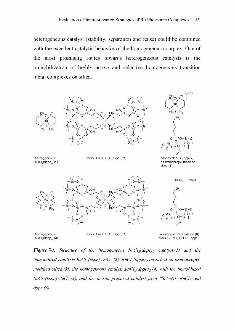
Evaluation of Immobilization Strategies of Ru Phosphine Complexes 115
heterogeneous catalyst (stability, separation and reuse) could be combined
with the excellent catalytic behavior of the homogeneous complex. One of
the most promising routes towards heterogeneous catalysts is the
immobilization of highly active and selective homogeneous transition
metal complexes on silica.
C X )P CI P
Ph2 Ph2
homogeneous
RuCI2(dppe)2(1)
—Sr
"Si-CX/
O'
o
o^Sl-I
Sk„
o
'OI „OHSl „-
O'
HOx !
-Ph E^x/Sl
o
-Si-O
\
\-Si-
oI „o.
"SiI
Si
,R. ci p:
Ru
k / ! \
/\ „,P CI P^ ^\Sl ^-^Ph Ph"-^ „Si
I OH HO !
.0 O.
O
OI „O
-Suo
O'
.Ox I
SiI
„o'Si
\/-Si—
o
lxn-Sr
.O-Si
•o\
I/
Sl-o.O-Si-
/
/
o
immobilized RuCI2(bspe)2 (2)
Ph, Ph,
P. 2CI P.2
f Rù
V*. p-
Ph, Ph.
CI P.
CI"
O' I "O-Si-0
-Si
/ ô °— Si-O
/b\
.0/
adsorbed RuCI2(dppe)2on ammopropyl-modifiedsilica (3)
Ph, Ph,P. CI P^\vRu
/ I \
P CI P
Ph2 Ph2
—-Sro
.Sko o
Si-O^ I I „OHSk „Sl
„
"O ^-^!o
-kO
-Si-O
\
\-Si-
'O
Si SkI I OH
O^ „OSi
O
Ph
Px CI P.
\yRu
/ ! \
P CI p.Ph Ph
o' \/I „O-Si—
.Sk Ioo L
HO^ I I „0SiPiv\. „Sk „Skp ^-^ O O
\
O'i:
„-\ „Ovl„0-Sr„Si Si /
HO I I'
Si /.
Si
I'
oo-
\
RuCI, + dppe
NH2
.SkO I O-Si-0
-Si
/ ô °--Si-O
/b\
/
homogeneous
RuCI2(dppp)2 (4)
immobilized RuCI2(bspp)2 (5) in situ generated catalyst (6)from "Si"-NH2-RuCI3 + dppe
Figure 7-1. Structure of the homogeneous RuCE(dppe)2 catalyst (1) and the
immobilized catalysts RuCÏ2(bspe)2/Si02 (2), RuCE(dppe)2 adsorbed on aminopropyl-
modified silica (3), the homogeneous catalyst RuCE(dppp)2 (4) with the immobilized
RuCl2(bspp)2/Si02 (5), and the in situ prepared catalyst from "Si "-NH2-RUCI3 and
dppe (6).

116 Chapter 7
Both adsorbed Ru complexes on a modified silica surface [21] and the
covalent anchoring of ruthenium-phosphine complexes have been proposed
[14,22]. A crucial property of these "heterogenized" homogeneous
catalysts is their stability with repetitive use. Considering these points, we
critically evaluated the two different strategies for the immobilization of
bidentate ruthenium-phosphine complexes on silica: covalent bonding via
functionalized ligands using RuCl2(bspe)2 and RuCl2(bspp)2, and
coordinative anchoring of RuCl2(dppe)2 and analogs.
The different catalysts investigated are depicted in Figure 7-1. Various
methods, including X-ray absorption spectroscopy, XPS, nitrogen
adsorption, DRIFTS, and ICP-OES were applied in order to characterize
the catalysts and to uncover the structural changes the catalysts underwent
with repetitive use.
7.3 Experimental
7.3.1 Preparation of the Covalently Bound RuCl2(bspe)2 Catalyst
All preparations were carried out under oxygen-free conditions employing
usual Schlenk techniques. Solvents were used in spectrophotometric purity,
degassed, and stored under argon. Scheme 7-1 shows the synthesis strategy
of the Ru-complex (2), covalently linked to the silica matrix. Starting from
l,2-bis(diphenylphosphino)ethane (dppe), the ligand l,2-bis[2'-(triethoxy-
silyl)ethylphenylphosphino] ethane (bspe) was synthesized with the
corresponding silyl groups that lead to the covalent linkage to the silica
matrix. Finally, the corresponding Ru complex was introduced into the
silica matrix by a solution sol-gel process.

Evaluation of Immobilization Strategies of Ru Phosphine Complexes 117
1) Li, THF
2)H20
hi)
Kr ^
Si(OEt)3
J„O^I„0N
Si
I
„Sil
SkI
o
Os I
.\Ph Ph^\ „Si
.P. CI P. ^~^
Ru
k. / I \„
„,P CI PC ^\ „O"-^Ph Ph""-^ „Si
O I
RuCI2(PPh3),acetone
r-° k J °^ ..Sk
„
O I o
o.
1)TE0S, THF
oxalic acid
2)THA, THF
1
\/ ^O—Si-O^ I
I .Sl
Si-O^ I
/ „Sio' o'
oI „OH
-Sk /
O'HOv I
Ph PI>-\ „.Si
;pv CI P. ^-^
9 ^o—SiOU „O /\
\ Si SkNI I OH
\ 0 0Si
C X )„P CI Pk
-^Ph pFT-
oI „o-
-Sko
.SiHO I
O.
-Si-
/
O'
SiI
Si
\/-Si
.O-Si'
•o\
i y
•Sl~o.O-Si-
/
o o-
/-Si"
\
Scheme 7-1. Synthesis of the immobilized RuCl2(bspe)2 hybrid catalyst (2). Starting
from l,2-bis(diphenylphosphino)ethane (dppe), the ligand l,2-bis[2'-(triethoxysilyl)-
ethylphenylphosphino]ethane (bspe) was synthesized via 1,2-bis(phenylphosphino)-
ethane (ppe). After complexation with bspe in a ligand exchange process from
RuCÏ2(PPh3)3, catalyst (2) was obtained.
f2-Bis(phenylphosphino)ethane (ppe). The phosphine (ppe) was prepared
in a similar manner as described in [23], using the following procedure:
100 ml tetrahydrofuran (THF), freshly distilled over sodium, was degassed
and stored in a 500 ml three-way flask under argon atmosphere. 4 g of

118 Chapter 7
lithium wire in pieces of 2 cm was added. In an ice bath at 0°C, 21.35 g of
l,2-bis(diphenylphosphino)ethane in THF was added dropwise under
heavy stirring, resulting in a tawny solution. After 2 h of refluxing at 80°C,
the color changed again to dark brown. The solution was separated from
the lithium and cooled with ice to 0°C. For the precipitation of lithium
hydroxide, 15 ml water in 60 ml THF was added before drying in vacuum.
The product l,2-bis(phenylphosphino)ethane (10.32 g, 78%) was extracted
with 100 ml diethylether after addition of 200 ml water, followed by
vacuum distillation at 0.13 mbar and 160°C. 1H-NMR: (500 MHz, C6D6,
28°C) ô = 1.5 - 1.9 (m, 4H, CH2), 3.83 (m, 1H, PH), 4.25 (m, 1H, PH), 7.0
(m, 6H, ArH), 7.25 (m, 4H, ArH); 31P-NMR: (200 MHz, C6D6, 28°C) ô =
-12.93. IR: (neat) 3068, 3053, 2281 (s,v(P-H)), 1481, 1435, 730, and
694 cm-1.
f2-Bis[2'-(triethoxysilyl)ethylphenylphosphino]ethane (bspe). In the next
step, the biphosphine (ppe) was further modified to introduce silyl groups.
4.829 g (19.6 mmol) l,2-bis(phenylphosphino)ethane and 7.46 g
(39.2 mmol) vinyltriethoxysilane were exposed to UV-light in a water-
cooled fused quartz vessel for 72 h (12.2 g bspe, 99%), in a similar way as
reported in [24]. 1H-NMR: (500 MHz, C6D6, 28°C) ô = 0.62 - 0.84 (m,
4H, PCH2C7/2Si), 1.10 (t, J = 7.0, 18H, SiOCH2C//5), 1.72 - 2.4 (m, 8H,
VCH2CH2V, PC7/2CH2Si), 3.71 (q, J = 6.98, 12H, SiOC7/2CH3), 7.0 - 7.5
(m, 10H, ArH); 31P-NMR: (200 MHz, C6D6, 28°C) ô = -12.93. IR: (neat)
3064, 2974, 2926, 2889, 1482, 1434, 1390, 1293, 1261, 1167, 1103, 1080,
958, 773, 743, 725, and 697 cm-1. No signal was observed for v(P-H).
RuCl2(bspe)2 and the synthesis of the hybrid gel. Finally, the transition
metal was introduced and the hybrid gel was prepared. For this purpose,
2.40 g (3.83 mmol) bspe was added to a suspension of 1.86 g (1.94 mmol)

Evaluation of Immobilization Strategies of Ru Phosphine Complexes 119
RuCl2(PPli3)3 in 20 ml acetone and stirred for 12 h. A dark brown oily
material was obtained after the solvent had been removed. Analysis of the
oily product: 1H-NMR: (500 MHz, C6D6, 28°C) ô = 0.90 - 0.95 (m, 4H,
PCH2C7/2Si), 1.10 (t, J = 7.0, 18H, SiOCH2C//5), 1.2 - 2.4 (m, 8H,
VCH2CH2V, PC7/2CH2Si), 3.71 (q, J = 6.98, 12H, SiOC7/2CH3), 7.0 - 7.6
(m, 10H, ArH); 31P-NMR: (200 MHz, C6D6, 28°C) ô = -4.08. IR: (neat)
3064, 2973, 2924, 2886, 1476, 1433, 1390, 1165, 1101, 1075, 958, 741,
and 692 cm-1.
To 20.05 g tetraethoxysilan in 10 ml THF, 3.00 g RuCl2(bspe)2 complex
was added slowly. 10 ml of 0.001 M oxalic acid in 30 ml THF was added
dropwise with stirring. The moderate stirring of the solution was continued
for 24 h. The addition of 4.07 g trihexylamine in 15 ml THF caused the
gelation within a few minutes. The gel was kept under argon and aged for
4 days. During this time, tetrahydrofuran, which was released by the gel,
was replaced by ethanol [25].
Finally, the resulting RuCl2(bspe)2/Si02 (2) was crushed after evaporation
of the solvent, washed with ethanol, and dried in vacuum at 60°C. 3lP-
MAS-NMR of yellowish catalyst (2): (162 MHz, 28°C) ô = 33.46; 29si-
MAS-NMR: (80 MHz, 28°C) ô = -93.5 (Si(OH)2(OH)2), -101.38
(Si(OH)(OSi)3), -109.49 Si(OSi)4.
7.3.2 Preparation of the Adsorbed Catalyst RuCl2(dppe)2 on Amino-
propyl-modified Silica
RuCl2(dppe)2 (1) was synthesized from 1.00 g RuCl2(PPfi3)3 in a 20 ml
acetone suspension by ligand exchange with 0.85 g dppe under argon
atmosphere [26]. After filtration, washing with acetone and methanol, the
yellow precipitate was dried in vacuum and analyzed with lH- and 31P-
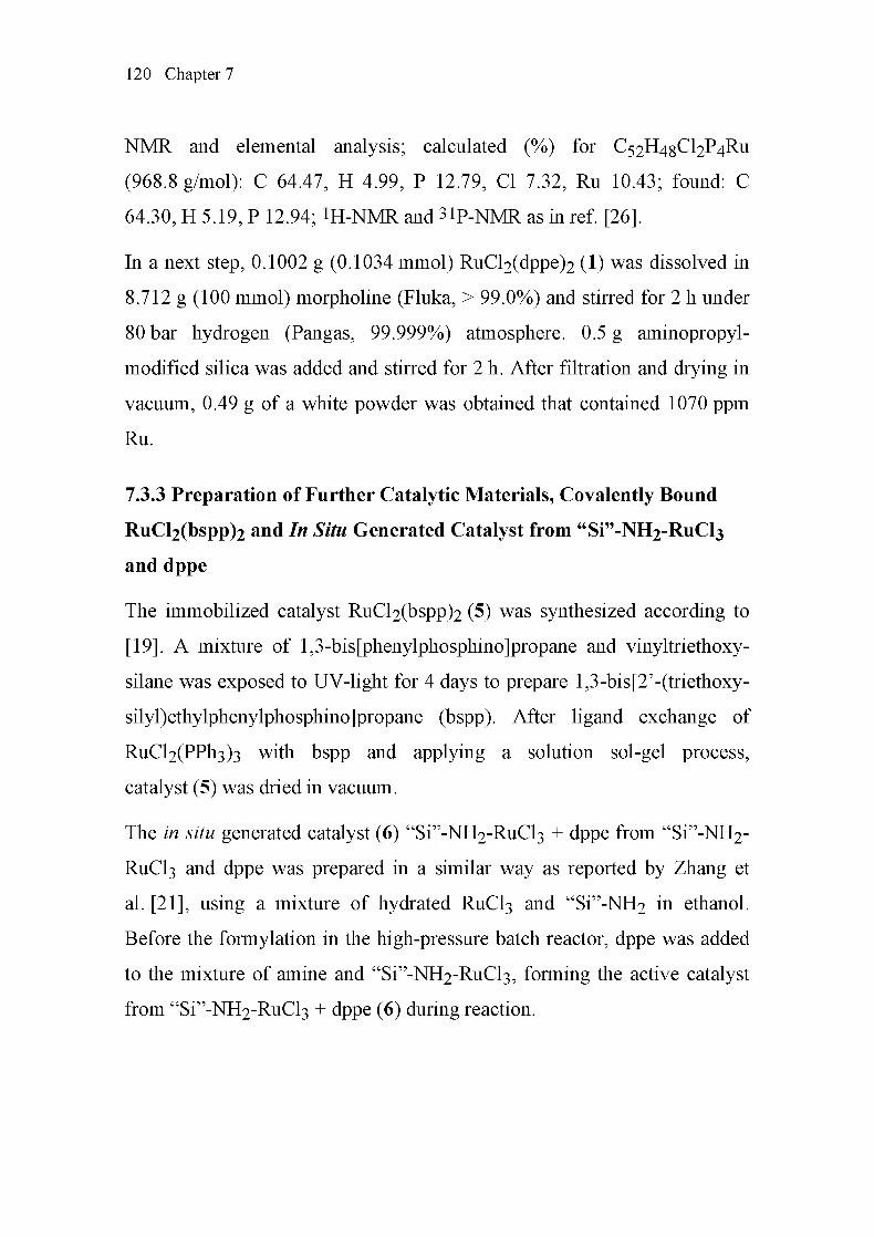
120 Chapter 7
NMR and elemental analysis; calculated (%) for C52H4gCl2P4Ru
(968.8 g/mol): C 64.47, H 4.99, P 12.79, CI 7.32, Ru 10.43; found: C
64.30, H 5.19, P 12.94; 1H-NMR and 3lP-NMR as in ref. [26].
In a next step, 0.1002 g (0.1034 mmol) RuCl2(dppe)2 (1) was dissolved in
8.712 g (100 mmol) morpholine (Fluka, > 99.0%) and stirred for 2 h under
80 bar hydrogen (Pangas, 99.999%) atmosphere. 0.5 g aminopropyl-
modified silica was added and stirred for 2 h. After filtration and drying in
vacuum, 0.49 g of a white powder was obtained that contained 1070 ppm
Ru.
7.3.3 Preparation of Further Catalytic Materials, Covalently Bound
RuCl2(bspp)2 and In Situ Generated Catalyst from "Si"-NH2-RuCl3
and dppe
The immobilized catalyst RuCl2(bspp)2 (5) was synthesized according to
[19]. A mixture of l,3-bis[phenylphosphino]propane and vinyltriethoxy-
silane was exposed to UV-light for 4 days to prepare l,3-bis[2'-(triethoxy-
silyl)ethylphenylphosphino]propane (bspp). After ligand exchange of
RuCl2(PPli3)3 with bspp and applying a solution sol-gel process,
catalyst (5) was dried in vacuum.
The in situ generated catalyst (6) "Si"-NH2-RuCl3 + dppe from "Si"-NH2-
RUCI3 and dppe was prepared in a similar way as reported by Zhang et
al. [21], using a mixture of hydrated RUCI3 and "Si"-NH2 in ethanol.
Before the formylation in the high-pressure batch reactor, dppe was added
to the mixture of amine and "Si"-NH2-RuCl3, forming the active catalyst
from "Si"-NH2-RuCl3 + dppe (6) during reaction.

Evaluation of Immobilization Strategies of Ru Phosphine Complexes 121
7.3.4 Catalytic Formylation of Amines with Supercritical Carbon
Dioxide
In a typical procedure, the corresponding amine and the catalyst were
poured into a 500 ml high-pressure stainless steel autoclave (see chapter 2,
section 2.1.1). After closing, the reactor was flushed three times with
hydrogen (Pangas, 99.999%), then heated to 100°C, adjusting the hydrogen
pressure to 80 bar. 100 g liquid carbon dioxide (Pangas, 99.995%),
quantified by a Rheonik mass flow controller (RHM 01, RHE 02), was
added using a compressor from a C02 gas cylinder equipped with a dip
tube. The end of this filling process marked the starting time of the
reaction, which was carried out at a constant stirring rate of 300 min-1. The
final total pressure at the start was about 200 bar at 100°C. A gas
Chromatograph (HP-6890) equipped with a HP-5 capillary column (30 m x
0.32 mm x 0.25 urn) and a flame ionization detector (FID) was used for
analyzing the reaction mixture after filtering (0.45 urn pore size). The
identification of the products was carried out on a gas Chromatograph (HP-
6890) coupled to a mass spectrometer (HP-5973). The ruthenium content of
the liquid phase and the ruthenium loadings of the solid catalysts were
determined by inductively coupled plasma optical emission spectroscopy
(ICP-OES).
7.3.5 Physico-chemical Characterization Using X-ray Absorption
Spectroscopy (XANES, EXAFS) and Further Characterization
Methods (XPS, Nitrogen Physisorption, NMR, and DRIFTS)
X-ray absorption near edge structure and extended X-ray absorption fine
structure experiments were performed at the Swiss-Norwegian beamline
(SNBL) at the European Synchrotron Radiation Facility (ESRF) in

122 Chapter 7
Grenoble, France. The storage ring operates at 6 GeV with a ring current of
200 mA. The monochromator used consists of Si(lll) channel-cut. Higher
harmonics were effectively removed by a double-bounce gold-coated
mirror system. Each of the three ionization chambers was filled with a
combination of the gases Ar, N2 and Kr (Iq At, It and Iref 30% Kr and 70%
N2) to record the intensity of the incident and the transmitted X-rays. The
samples were placed between the first and second ionization chamber, with
the RUCI3 reference pellet placed between the second and third ionization
chamber. For low-concentration samples, the X-ray absorption spectra
were in addition measured in fluorescence mode. The EXAFS spectra were
taken under stationary conditions in the step-scanning mode around the Ru
K-edge (22.117 keV) from 21.900 keV to 22.800 keV with a RuCl3 pellet
as reference. The raw data were energy-calibrated with the Ru K-edge
energy of the RUCI3 pellet at 22.120 keV [27] at the first inflection point,
background-corrected and normalized using WINXAS 3.0 software [28].
The EXAFS data was Fourier-transformed to the kl-weighted functions in
the interval k = 3-13.0Â_1 and fitted to R-space. Phase shifts and
backscattering amplitudes were calculated using FEFF 6 [29]. Deviations
of the distances were within ±0.02 Â, and those for the coordination
numbers were within ±0.5.
For the identification of the structure of catalyst (2) and catalyst (3),
pressed pellets of the corresponding materials were used in which the metal
content was adjusted to yield an absorption ixd of about 1.5 at the Ru K
absorption edge. For fluorescence EXAFS, a pellet of about 3 mm
thickness was used at a 45° angle to the beam, complemented by the 13-
element fluorescence detector (13-element Ge solid-state detector,
Canberra). The fluorescence signals from the 13 detector elements were

Evaluation of Immobilization Strategies of Ru Phosphine Complexes 123
pre-amplified directly and then fed into the XIA digital pulse processing
electronics (DXP 2X). The digital electronics features full 8k MCA capa¬
bility for each detector element. The Ru Ka-fluorescence regions were
selected and calibrated on the basis of a full spectrum for each channel,
collected prior to the measured scans. The signal of interest (Ru Ka-
fluorescence) versus the (elastic/matrix) background was optimized with
the aid of filters. The resulting 13 SCA data were added up after each
measurement. The corresponding liquid reaction mixtures were
investigated in the stainless steel EXAFS cell with Kapton windows, both
in transmission and in fluorescence mode, as depicted in Figure 7-2 and
described in detail in chapter 2, section 2.2.1. The volume is about 2 ml,
and a long path length of 4 cm was chosen for the transmission EXAFS
experiments because of the low ruthenium concentration in the samples
(50 - 100 ppm). For the same reason, fluorescence EXAFS spectra were
recorded at a 90° angle, too. Figure 7-2 shows that both fluorescence and
transmission EXAFS spectra could be taken at the same time. The 0.5 mm
x 5 mm beam was focused on the center of the spectroscopic cell by use of
a moveable x, z, 0-table from Newport.
X-ray photoelectron spectroscopy (XPS). Surface analytical information
was obtained by XPS using a Leybold Heraeus LHSll MCD instrument
[30] and Mg Ka (1253.6 eV) radiation. The catalyst powder was pressed
into a sample holder, evacuated slowly in a load lock to 10-6mbar and
transferred to the analysis chamber (typical pressure < 10"9mbar). The
peaks were energy-shifted to the binding energy of C(ls) to correct the
charging of the material. The surface composition of the catalysts was
determined from the peak areas of C(ls), 0(1 s), Si(2p), Ru(3d), which
were computed after subtraction of the Shirley-type background by

124 Chapter 7
empirically derived cross-section factors [31]. The relative error of the
analysis is estimated to be within ±5%.
Combined
transmission/fluorescence
EXAFS cell
4 cm
Reference
sample
X-raybeam
5 mm x 0 5 mmfl
Ionization chamber 1 Ionization chamber 2 Ionization chamber 3
Cr-filter
13 element
fluorescence
Ge-detector
Figure 7-2. Schematic representation of the experimental setup with the stainless steel
EXAFS cell for simultaneous measurements in transmission andfluorescence mode at
the Ru K-edge, as performed at SNBL (ESRF, Grenoble). The distance of the 13-
element Ge solid-state detector is adjustable, and the use ofthe filterfoil depends on the
kind ofsample used (for details, see text and chapter 2, section 2.2.1).
Nitrogen physisorption. The BET surface areas Sbet were determined
from nitrogen physisorption at 77 K using a Micromeritics TriStar 3000
instrument. Prior to the measurements, the samples were heated in vacuum
at 60°C for 6 h. BET surface areas were calculated in a relative p/po
pressure range from 0.05 to 0.2, assuming a cross-sectional area of
0.162 nm2 for the adsorbed nitrogen molecule.
Nuclear magnetic resonance spectroscopy (NMR). IH-NMR spectra were
taken on a Bruker Avance 500 instrument at an operation frequency of
500.12 MHz. Liquid 31P-NMR spectra were measured on a Bruker
Avance 500 at 202.4 MHz. Solid-state 31P-MAS-NMR spectra of
catalyst (2) and the corresponding 29Si-MAS-NMR spectra were carried
out on a Bruker AMX 400 at 162.0 MHz and at 79.5 MHz for the 29Si-
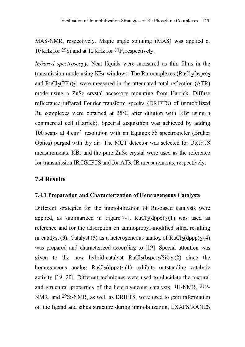
Evaluation of Immobilization Strategies of Ru Phosphine Complexes 125
MAS-NMR, respectively. Magic angle spinning (MAS) was applied at
10 kHz for 29Si and at 12 kHz for 3lP, respectively.
Infrared spectroscopy. Neat liquids were measured as thin films in the
transmission mode using KBr windows. The Ru-complexes (RuCl2(bspe)2
and RuCl2(PPh)3) were measured in the attenuated total reflection (ATR)
mode using a ZnSe crystal accessory mounting from Harrick. Diffuse
reflectance infrared Fourier transform spectra (DRIFTS) of immobilized
Ru complexes were obtained at 25°C after dilution with KBr using a
commercial cell (Harrick). Spectral acquisition was achieved by adding
100 scans at 4 cm-1 resolution with an Equinox 55 spectrometer (Bruker
Optics) purged with dry air. The MCT detector was selected for DRIFTS
measurements. KBr and the pure ZnSe crystal were used as the reference
for transmission IR/DRIFTS and for ATR-IR measurements, respectively.
7.4 Results
7.4.1 Preparation and Characterization of Heterogeneous Catalysts
Different strategies for the immobilization of Ru-based catalysts were
applied, as summarized in Figure 7-1. RuCl2(dppe)2 (1) was used as
reference and for the adsorption on aminopropyl-modified silica resulting
in catalyst (3). Catalyst (5) as a heterogeneous analog of RuCl2(dppp)2 (4)
was prepared and characterized according to [19]. Special attention was
given to the new hybrid-catalyst RuCl2(bspe)2/Si02 (2) since the
homogeneous analog RuCl2(dppe)2 (1) exhibits outstanding catalytic
activity [19, 20]. Different techniques were used to elucidate the textural
and structural properties of the heterogeneous catalysts. iH-NMR, 31P-
NMR, and 29Si-NMR, as well as DRIFTS, were used to gain information
on the ligand and silica structure during immobilization, EXAFS/XANES

126 Chapter 7
to identify the structure around the Ru absorber atom, and nitrogen
adsorption for surface area and pore structure analysis.
The iH-NMR spectrum of the complex RuCl2(bspe)2 showed a similar
ligand structure as the uncomplexed ligand bspe, only the peak in the 31P-
NMR was shifted to -4.08, because of electronic effects of the ruthenium-
phosphorus bond. The 31P-MAS-NMR spectrum of catalyst (2) in
Figure 7-2 indicated that no significant change of the geometric structure in
the coordination sphere of the phosphorus atoms had taken place during the
immobilization process. Beneath the shifted main peak at 33.46 ppm, side¬
bands were observed in the spectra of the solid material, caused by the
sample rotation. The condensation degree of catalyst (2) was determined by
applying 29Si-MAS-NMR (Figure 7-3). Three distinguishable peaks
corresponding to different moieties of silicon atoms with four oxygen
neighbors were discernible (Figure 7-3), the chain- (Q2, Si(OH)2(OSi)2) at
-93.5 ppm, the bridgehead- (Q3, Si(OH)(OSi)3) at -101.38 ppm, and the
completely condensed hydroxysilanes (Q4, Si(OSi)4) at -109.49 ppm.
The DRIFT spectrum of catalyst (2) further confirmed the completed
condensation. The typical strong signals at 2974, 2926 and 2889 cm-1 of
the asymmetric and symmetric stretchings of CH2 and CH3 of the ethoxy
groups of the neat ligand disappeared upon immobilization. Moreover, a
band of medium intensity at 3691 cm-1 revealed the presence of free silanol
groups. New signals attributable to the CH2 groups of the immobilized
ligand appeared at 2956, 2931, 2870 and 2859 cm-1 and were accompanied
by a weak signal at 3060 cm-l, originating from the v(C-H) modes of the
phenyl rings. Additional signals at 747 and 695 cm-1 (out-of-plane ô(C-H)
and ring deformation) and at 724 cm-1 (v(P-CH2)) [32] demonstrated the
presence of methylenephenylphosphine groups on the silica support.

Evaluation of Immobilization Strategies of Ru Phosphine Complexes 127
b) 29Si-MAS-NMR
a)31P-MAS-NMR side bands
^«^»^S»*^»»»^
(ppm)
HOv ,OSlSl
Sio' "0S|
SlOv ,OSlSl
sid' "osi
V /
-100
(ppm)
Figure 7-3. Solid state a) 31P-MAS-NMR and b) 29Si-MAS-NMR of the immobilized
catalyst RuCEßspe)2 (2).
The XANES and the corresponding k1-weighted Fourier-transformed
EXAFS spectra of the covalently bound catalyst (2) and the adsorbed
catalyst (3) are shown in Figure 7-4. For comparison, the spectrum of the
covalently bound catalyst (5) is also shown. The XANES spectra are
similar for all three immobilized catalysts. Note that variations were found,
in correspondence with a previous study of RuCl3(PPfi3)3 and RUCI3 [33].
Even slight changes in the symmetry and ligands usually affect the near
edge structure of such complexes due to different multiple scattering paths
[34]. The backscattering amplitude of the first nearest neighbors (Figure 7-

128 Chapter 7
4b) shows a variation in both the covalently immobilized and adsorbed
complexes. This may be attributed to a slight variation in the local structure
of the immobilized complexes. In principle, two covalent linkages are
possible for each ligand. Depending on its incorporation in the silica
matrix, the Ru-P distance may vary to a certain extent, a consequence of
the structurally slightly different species in the silica matrix.
RuCI2(bspe)2/Si02 (2)
RuCI2(dppe)2/Si02 (3)
^RuClibsppySiO, (5)0 0000'
RuCI2(bspe)2/Si02 (2)
RuCI2(dppe)2/Si02 (3)^RuCL(bspp),/SiO,(5)
22 1 22 2 22 3
E/keV
22 4 22 5 3 4 5
R/A
Figure 7-4. a) X-ray absorption near edge structure at the Ru K-edge of the
immobilized RuCl2(bspe)2 (2), the adsorbed RuCE(dppe)2 (3), and the immobilized
RuCl2(bspp)2 (5) catalysts; and b) the corresponding Fourier-transformed spectra of
the k1-weightedEXAFSfunctions.
Nevertheless, the structural data extracted from EXAFS spectra of the
immobilized phosphine complexes and from RuCl2(dppe)2 (1) as reference
show that the immobilized catalysts (2) and (5) have similar local structures
(Table 7-1). Like the homogeneous catalyst (1) and the adsorbed
catalyst (3), they show backscattering peaks at 2.35 Â for the Ru-P distance
and at 2.43 Â for the Ru-Cl bond length. The Ru-P and the Ru-Cl distances
of both catalysts are in agreement with the Ru-P and Ru-Cl distances of the
well-characterized complex RuCl2(dppm)2 [35]. The altered coordination
numbers found in catalyst (3) may be explained by a certain coordination to
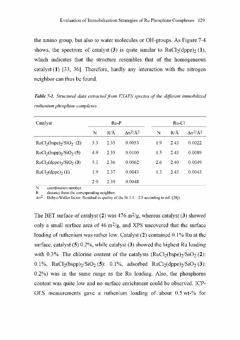
Evaluation of Immobilization Strategies of Ru Phosphine Complexes 129
the amino group, but also to water molecules or OH-groups. As Figure 7-4
shows, the spectrum of catalyst (3) is quite similar to RuCl2(dppe)2 (1),
which indicates that the structure resembles that of the homogeneous
catalyst (1) [33, 36]. Therefore, hardly any interaction with the nitrogen
neighbor can thus be found.
Table 7-1. Structural data extractedfrom EXAFS spectra of the different immobilized
ruthenium phosphine complexes
Catalyst Ru-P Ru-Cl
N R/Â Ao2/Â2 N R/Â Ao2/Â2
RuCl2(bspe)2/Si02 (2) 3.3 2.35 0.0053 1.9 2.43 0.0022
RuCl2(bspp)2/Si02 (5) 4.9 2.35 0.0100 1.5 2.43 0.0089
RuCl2(dppe)2/Si02 (3) 5.1 2.36 0.0062 2.6 2.40 0.0049
RuCl2(dppe)2(l) 1.9
2.0
2.37
2.39
0.0043
0.0048
1.3 2.43 0.0043
N coordination number.
R distance from the corresponding neighbor.Aa2 Debye-Waller factor. Residual as quality of the fit 1.1 - 2.5 according to ref [28]).
The BET surface of catalyst (2) was 476 m2/g, whereas catalyst (3) showed
only a small surface area of 46 m2/g, and XPS uncovered that the surface
loading of ruthenium was rather low. Catalyst (2) contained 0.1% Ru at the
surface, catalyst (5) 0.2%, while catalyst (3) showed the highest Ru loading
with 0.3%. The chlorine content of the catalysts (RuCl2(bspe)2/Si02 (2):
0.1%, RuCl2(bspp)2/Si02 (5): 0.1%, adsorbed RuCl2(dppe)2/Si02 (3):
0.2%) was in the same range as the Ru loading. Also, the phosphorus
content was quite low and no surface enrichment could be observed. ICP-
OES measurements gave a ruthenium loading of about 0.5 wt-% for

130 Chapter 7
catalyst (2), 0.15 wt-% for catalyst (5), and 0.10 wt-% for catalyst (3),
respectively.
7.4.2 Catalytic Formylation of Amines Using Immobilized
RuCl2(bspe)2
The catalytic activity of the immobilized RuCl2(bspe)2 (2) was tested in the
formylation of various amines with hydrogen and carbon dioxide
(Table 7-2). Note that the substrates contained an additional functional
group (ether or hydroxyl). The highest catalytic activity related to the
catalyst mass was achieved for formylmorpholine synthesis - 164 mmol
product per g catalyst - corresponding to a TON of 3416.
Table 7-2. Catalytic formylation of functionalized amines with supercritical carbon
dioxide using the immobilizedRuCE(bspe)2/SiO'2 catalyst (2)
Run Amine Catalytic activity TON
/(mmol product/g catalyst)
1 Morpholine 164 3416
2 3-Methoxypropylamine 148 3078
3 2-Ethylaminoethanol 48 974
4 2-Methylaminoethanol 37 760
Conditions: 100 mmol amine, 100 g C02, 80 barH2 at 100°C, 0.5 g catalyst, 100°C, 20 h.
Selectivity: about 100%, no by-product identified.
The formylation of the primary amine 3-methoxypropylamine, with a
catalytic activity of 148 mmol per g catalyst in 20 h and a TON of 3078,
was about as efficient as that of morpholine. The formylation of secondary
amines containing a free hydroxyl-group, 2-ethylaminoethanol (48 mmol/g,
TON of 974) and 2-methylaminoethanol (37 mmol/g, TON of 760)

Evaluation of Immobilization Strategies of Ru Phosphine Complexes 131
occurred considerably slower. As expected, catalyst (2) was more active
than the reference catalyst (5) (TON of 1270 for (5), TON of 3078 for (2)).
Therefore, further attention was mainly given to catalyst (2).
CZI RuCI2(bspe)2/Si02 (2)^ RuCI2(dppe)2/Si02 (3)
< 0 1 mmol/g cat
-7ZZZA I I I I2 3 4
exp. no.
Figure 7-5. a) Changes of the conversion in mmolproduct per g catalyst and turnover
number (TON) of the immobilized RuCl2(bspe)2 (2) catalyst during four recycling
loops. Reaction conditions: 100 mmol mpa, 0.5 g catalyst, 100 g CO2, 80 bar H2 initial
partial pressure, 6 h and 100°C; b) variation of the catalytic activity during four
recycling loops ofthe immobilized catalyst (2) compared with catalyst (3).
In order to test its behavior during recycle, catalyst (2) was reused four
times in the formylation of 3-methoxypropylamine. After each run, the
reaction mixture was filtered off and the catalyst was washed with 20 ml
distilled water and finally dried in vacuum for 24 h. Water was used in this
step, since it is a reaction by-product. Figure 7-5a shows the catalytic
activity related to the catalyst mass in the synthesis of 3-methoxy-
propylformamide and the corresponding turnover number after reuse of
catalyst (2). The formamide yield decreased with repeated use of the
catalyst. After four cycles, the initial catalytic activity related to the catalyst
mass of about 40 mmol/g dropped to 20 mmol/g, a behavior also reflected
by the turnover numbers.
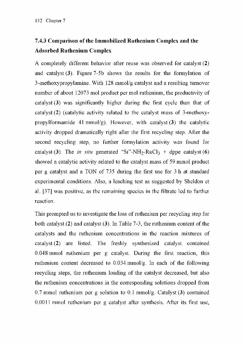
132 Chapter 7
7.4.3 Comparison of the Immobilized Ruthenium Complex and the
Adsorbed Ruthenium Complex
A completely different behavior after reuse was observed for catalyst (2)
and catalyst (3). Figure 7-5b shows the results for the formylation of
3-methoxypropylamine. With 128 mmol/g catalyst and a resulting turnover
number of about 12073 mol product per mol ruthenium, the productivity of
catalyst (3) was significantly higher during the first cycle than that of
catalyst (2) (catalytic activity related to the catalyst mass of 3-methoxy-
propylformamide 41 mmol/g). However, with catalyst (3) the catalytic
activity dropped dramatically right after the first recycling step. After the
second recycling step, no further formylation activity was found for
catalyst (3). The in situ generated "Si"-NH2-RuCl3 + dppe catalyst (6)
showed a catalytic activity related to the catalyst mass of 59 mmol product
per g catalyst and a TON of 735 during the first use for 3 h at standard
experimental conditions. Also, a leaching test as suggested by Sheldon et
al. [37] was positive, as the remaining species in the filtrate led to further
reaction.
This prompted us to investigate the loss of ruthenium per recycling step for
both catalyst (2) and catalyst (3). In Table 7-3, the ruthenium content of the
catalysts and the ruthenium concentrations in the reaction mixtures of
catalyst (2) are listed. The freshly synthesized catalyst contained
0.048 mmol ruthenium per g catalyst. During the first reaction, this
ruthenium content decreased to 0.034 mmol/g. In each of the following
recycling steps, the ruthenium loading of the catalyst decreased, but also
the ruthenium concentrations in the corresponding solutions dropped from
0.7 mmol ruthenium per g solution to 0.1 mmol/g. Catalyst (3) contained
0.0011 mmol ruthenium per g catalyst after synthesis. After its first use,

Evaluation of Immobilization Strategies of Ru Phosphine Complexes 133
only 2.1 jLimol ruthenium per g catalyst remained in the catalyst, the
catalytic activity related to the catalyst mass decreased to 4.8 mmol/g, and
after a second recycling step, a very low ruthenium concentration of
0.6 jLimol/g catalyst was measured and no more production of formamide
could be observed.
Table 7-3. Ruthenium concentrations of the immobilized RuCl2(bspe)2 catalyst (2) in
each recycling step during formylation of 3-methoxypropylamine with supercritical
carbon dioxide
Experiment number Ru in solid catalysta Ru in solution
(recycling step) /(mmol/g) /(umol/g)
0 0.048
1 0.034 0.706
2 0.036 0.267
3 0.028 0.281
4 0.017 0.123
a note: determination of Ru concentration in solid is less reliable than in solution.
7.4.4 Structural Analysis of the Solid Catalysts and the Soluble Species
after Reaction
In a similar manner as for the as-prepared Ru-catalysts, Ru K-edge XANES
and EXAFS spectra of catalysts (2) and (3) were taken after reaction
(Figure 7-6). Essentially, the spectra of catalysts (2) and (3) in as-prepared
state as well as after their reuse were similar. However, the shoulder at
1.2 Â was more prominent. The main backscattering peak was shifted to
slightly lower R-values and a shoulder appeared at 2.5 Â. Moreover, in the
case of catalyst (3) the concentration of Ru with 0.02 wt-% was
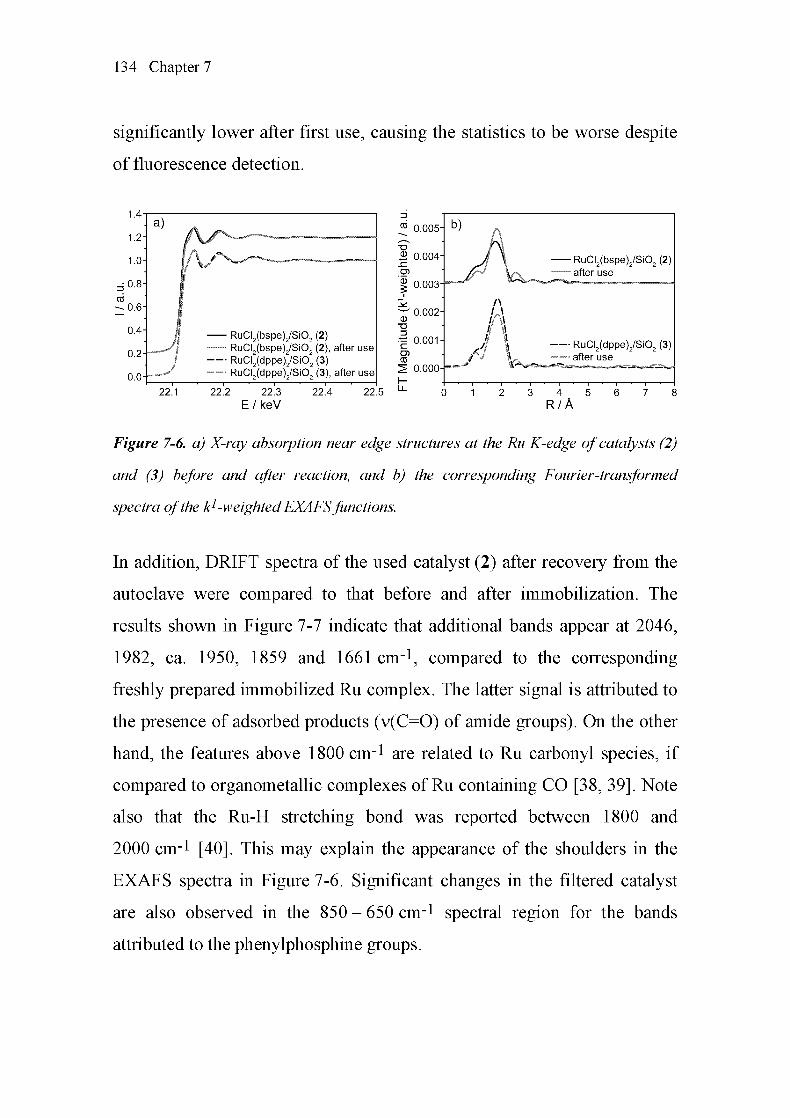
134 Chapter 7
significantly lower after first use, causing the statistics to be worse despite
of fluorescence detection.
1 4
1 2
1 0
08
06
04
0 2-f
00
- RuCI2(bspe)2/Si02 (2)- RuCI2(bspe)2/Si02 (2), after use
- RuCI2(dppe)2/Si02 (3)- RuCI (dppe) /SiO (3), after use
0 005-
S 0 004-
S 0 003-
^0 002H
T3
| 0 001-
CO
^ 0 000-r—'
b)
RuCI2(bspe)2/Si02 (2)after use
A
Mi \\i \
'i RuCI2(dppe)2/Si02 (3)after use
22 1 22 2 22 3
E/keV
22 4 22 5 4
R/A
Figure 7-6. a) X-ray absorption near edge structures at the Ru K-edge of catalysts (2)
and (3) before and after reaction, and b) the corresponding Fourier-transformed
spectra ofthe kl-weightedEXAFSfunctions.
In addition, DRIFT spectra of the used catalyst (2) after recovery from the
autoclave were compared to that before and after immobilization. The
results shown in Figure 7-7 indicate that additional bands appear at 2046,
1982, ca. 1950, 1859 and 1661 cm-1, compared to the corresponding
freshly prepared immobilized Ru complex. The latter signal is attributed to
the presence of adsorbed products (v(C=0) of amide groups). On the other
hand, the features above 1800 cm-1 are related to Ru carbonyl species, if
compared to organometallic complexes of Ru containing CO [38, 39]. Note
also that the Ru-H stretching bond was reported between 1800 and
2000 cm-l [40]. This may explain the appearance of the shoulders in the
EXAFS spectra in Figure 7-6. Significant changes in the filtered catalyst
are also observed in the 850 - 650 cm-l spectral region for the bands
attributed to the phenylphosphine groups.

Evaluation of Immobilization Strategies of Ru Phosphine Complexes 135
Figure 7-7. DRIFT spectra of the RuCl2(bspe)2 catalyst a) before immobilization, b)
immobilized RuCl2(bspe)2 (2) before reaction, and c) immobilized RuCE(bspe)2 (2)
after reaction.
As mentioned before, after the first use of catalyst (2), soluble ruthenium
species were found in the product solution. With a low concentration of
about 0.7 jLimol/g solution, generally fluorescence mode is favored [7, 41].
In a recent study, we carried out transmission EXAFS experiments at a
concentration as low as 2 jiimol/g solution [33]. These experiments inspired
us to compare both fluorescence and transmission EXAFS data. In
Figure 7-8, the spectra obtained from the liquid solution of catalyst (2) are
depicted in the fluorescence and in the transmission mode. Both methods
led to the same whiteline and near edge structure. Note that in both cases
the Ru concentration was about 70 ppm and the spectra were taken during
1 h. It seems that due to the long path length of the liquid cell (4 cm) and

136 Chapter 7
the high energy of the Ru K-edge, transmission EXAFS data are of similar
quality as the fluorescence EXAFS data.
1.0-
0.8-
d
cd 0.6-
^ j I
Fluorescence EXAFS
Transmission EXAFS
22.1 22.2 22.3 22.4 22.5
E/keV
Figure 7-8. Comparison offluorescence EXAFS data taken at the Ru K-edge in the
fluorescence mode (dashed line) and in the transmission mode (solid line), taken from
the solution after the reaction of catalyst (2). The concentration of the catalyst in the
liquidphase was 71 ppm. Total scanning time was about 1 hour.
To gain more information about the structure of the soluble species after
reaction, the liquid reaction mixtures after reaction under standard
conditions with catalyst (2) and (3) were compared to those from the
homogeneous catalyst (1) after similar reaction exposure. The spectrum of
catalyst (2) was measured during 5 h, whereas for catalyst (3) 3 h were
sufficient due to the higher Ru-concentration. As depicted in Figure 7-9,
the spectrum resulting from the product solution of catalyst (2, solid black
line) differs strongly from those of catalyst (3, dashed black line) and
catalyst (1, solid gray line). It seems that the catalytically active species on
catalyst (3) exhibit a structure similar to that of the homogeneous
RuCl2(dppe)2 (1) after reaction. This implies that catalyst (3) desorbs
during reaction, homogeneously catalyzes the reaction, and remains in the
rv^-*-/--
Evaluation of Immobilization Strategies of Ru Phosphine Complexes 137
liquid product mixture. The structure of the soluble part of catalyst (2),
however, was much different. The peak at 1.8 Â was shifted to significantly
lower values and also was less intense. This indicates that other ligands,
such as amino or hydroxyl groups, are coordinated to the Ru center.
RuCI2(bspe)2/Si02 (2)
RuCI2(dppe)2/Si02 (3)— free RuCI (dppe)
22 1 22 2 22 3
E/keV
22 4 22 5
RuCI2(bspe)2/Si02 (2
RuCI2(dppe)2/Si02 (3)— free RuCI2(dppe)2
22 1 22 2
E/keV
22 3
k/A-1
to
^ 0 0015"
d)
k50 0010-
^ I \
Magnitude0
0
0
0
0
0
0
0
O
Ol
Ji\I \^^^^^^— r*^
LL
R/A
Figure 7-9. Structural comparison of the Ru-complexes formed during the formylation
of 3-methoxypropylamine in the presence of hydrogen and carbon dioxide with
immobilized RuCE(bspe)2 (2, solid black line), adsorbed RuC'I^(dppe)2 (3, dashed line)
and RuCE(dppe)2 (1, solid gray line) using X-ray absorption spectroscopy at the Ru K-
edge; data taken in transmission mode; a) XAS spectra, b) XANES regions, c) k1-
weighted xßj^-functions and d) Fourier-transformed ^-weighted EXAFS functions
(k = 3.5- 13Â-1).

138 Chapter 7
This may also explain the change in the near edge structure, supporting the
conclusion that the modified phosphine ligands (catalyst (2)) are better
incorporated into the matrix than in the case of catalyst (3), where they are
evidently dissolved in the reaction mixture, resulting in XANES and
EXAFS spectra that are similar to catalyst (1) after reaction. For the spectra
of ruthenium complexes in the liquid phase, see chapter 4 and chapter 5.
7.5 Discussion
Two strategies for the immobilization of highly active Ru-phosphine
complexes - the coordination of the Ru to amine-modified silica, and the
covalent anchoring on silica via functionalized ligands - have been
evaluated with respect to their potential for the preparation of
heterogeneous Ru catalysts for the formylation of amines in supercritical
carbon dioxide. This encompasses the characterization of the prepared
grafted complexes, the catalytic behavior, the reuse, and the determination
of possible leached species.
The adsorption of homogeneous complexes on modified silica has been
reported in a number of studies [42] as a simple strategy. Zhang et al. [21]
recommended this procedure as well applicable to the hydrogénation of
carbon dioxide. The active catalyst was formed in situ from amine-
modified silica-supported ruthenium complexes ("Si"-NH2-RuCl3) by
addition of a phosphine (dppe or PPI13). As typical examples of the
adsorption strategy, we prepared this catalyst (6) and additionally grafted
the RuCl2(dppe)2 complex on an aminopropyl-modified silica surface
(catalyst (3)). EXAFS and XPS were applied to prove the successful
deposition of the Ru-complex on aminopropyl-modified silica.
Evaluation of Immobilization Strategies of Ru Phosphine Complexes 139
For the covalent linkage of the phosphine ligand, we prepared the new
covalently immobilized catalyst (2) RuCl2(bspe)2/Si02 with improved
activity compared to RuCl2(bspp)2/Si02 (5). Tai et al. [20] showed the bite
angle of the phosphine to be a decisive criterion, concluding that dppe and
dmpe as phosphine ligands are much more active than dppp, dppb and the
monophosphines in the formylation of amines with CO2. In chapter 5, the
Ru(dppe)2X2 catalyst proved to be the most active one as well. This
strengthens the motivation to immobilize a complex with a small bite angle
as encountered in catalyst (2). Different routes for the synthesis of
catalyst (2) using covalent linkage of the phosphine ligand were
considered. The route described in Scheme 7-1 afforded high yield, and all
the intermediates could be confirmed by NMR, IR, and/or EXAFS
spectroscopy. Also, the structure of the desired catalyst (2) was evidenced
using NMR, IR, EXAFS and XPS. On an alternative route, an amino group
instead of the triethoxysilane group was used for immobilization,
employing a nucleophilic substitution with the halogenalkyl group of a
correspondingly pre-treated silica support [43]. However, the reaction of
1,2-bis(phenylphosphino)ethane (ppe, see section 7.3.1 and Scheme 7-1)
and 3-aminopropene to l,2-bis(3'-aminopropylphenylphosphino)ethane in
the presence of benzene, UV-light, and AIBN as a radical starter [44]
resulted in a much lower yield of the desired ligand, and several by¬
products were evidenced by NMR.
Catalysts (2), (3), (5), as well as the in situ generated "Si"-NH2-RuCl3 +
dppe catalyst (6), proved to be catalytically active in the formylation of
differently functionalized amines. In contradiction to the experiments of
Zhang et al. [21], the adsorbed complexes in catalysts (3) and (6) were not
stable in the formylation of amines and hardly active after first reuse.

140 Chapter 7
Therefore, this simple procedure is not applicable under relatively harsh
reaction conditions with temperatures around 100°C and a pressure of
about 200 bar, and ICP-OES studies confirmed the strong leaching
behavior of as-prepared catalysts (3) and (6).
In comparison with these adsorbed complexes, the immobilized complex
RuCl2(bspe)2 (catalyst (2)) is more stable. As expected, the new
catalyst (2) with smaller bite angle of the phosphine was more active than
catalyst (5). The heterogenized catalysts (2) and (5) were not as active as
their homogeneous analogs, probably due to lower accessibility of the
active centers and the properties of the support. This has also been reported
in other comparative studies [42]. In order to gain more information about
the structure of the catalyst under reaction conditions, the deactivation
mechanism, and the structure of the leached species in the liquid reaction
mixture, X-ray absorption spectroscopy complemented leaching studies by
catalytic activity and ICP-OES.
XANES/EXAFS analysis of catalyst (3) after use, as well as of the liquid
solution, confirmed the strong leaching behavior under the reaction
conditions applied in this work. The structure of the remaining adsorbed
Ru-species was similar to that in the as-prepared catalyst, and thus the
conversion strongly decreased during reuse as a consequence of the
leaching of the catalytic species and possibly the formylation on the
anchoring amino groups. There is also another indication that the
catalytically active species acted as a homogeneous Ru-catalyst. According
to EXAFS, the structure of the formed homogeneous catalyst was similar to
that from RuCl2(dppe)2, which is known to act as efficient catalyst [17,
33]. Also re-adsorption during reaction as reported in [45, 46] could hardly
be observed.

Evaluation of Immobilization Strategies of Ru Phosphine Complexes 141
Although the loss of catalytic activity of the covalently immobilized
RuCl2(bspe)2 catalyst (2) during reuse was much less pronounced than that
of the adsorbed complexes (catalysts (3) and (6)), even in this case some
deactivation was found. This may be due to insufficient immobilization,
incomplete complexation, or the relatively harsh reaction conditions during
formylation, which are demanding with respect to catalyst stability. In fact,
the leached Ru complex in the liquid phase of the reaction mixtures
(Figure 7-8) exhibited a strikingly different XANES and EXAFS spectrum
compared to the immobilized Ru complexes, the complex formed from
RuCl2(dppe)2, and the Ru-complex adsorbed on aminopropyl-modified
silica (catalyst (3)). The structure of the solid part of catalyst (2) remained
similar to the original structure. Hence, the main reason for the loss in
activity of catalyst (2) is the partial dissolution by destruction of the
immobilized complex rather than by the leaching of the intact complex. To
illustrate this, compare the corrosion of the RU/AI2O3 catalyst in chapter 5
with the resulting in situ formation of active ruthenium phosphine
complexes during the reaction.
In general, deactivation of grafted complexes may occur by too weak
anchoring of the complexes, by destruction of the active complexes on the
silica matrix due to the relatively harsh reaction conditions, or by the
blocking of the active sites due to the deposition of carbonaceous
species/catalyst poison. Discrimination of these phenomena requires the
use of complementary methods for leaching studies [37] (catalytic studies,
ICP-OES) and spectroscopic techniques. In this study, both transmission
and fluorescence EXAFS were found to be well-suited characterization
tools to uncover the structure of both the liquid species and the
immobilized catalysts. Even though the concentration was rather low

142 Chapter 7
(50 ppm), structural information on the liquid Ru species could be gained.
Due to the high absorption edge of ruthenium (Ru K-edge at 22.12 keV),
EXAFS in transmission mode using a long path length cell was applicable,
giving similar results as fluorescence EXAFS. For the catalyst (3) used,
fluorescence EXAFS was the preferred method, since with 0.02%, the
concentration was small, and only a limited amount of sample after a
catalytic test was available. In addition, important information on the
covalently immobilized catalysts could be gained both by EXAFS and
DRIFTS indicating the formation of Ru-carbonyl complexes.
7.6 Conclusions
Different strategies for the immobilization of highly active Ru-phosphine
complexes applied for the formylation of amines in supercritical carbon
dioxide have been examined regarding their potential for the preparation of
corresponding heterogeneous catalysts. Best results with regard to activity
and stability during reuse were obtained with catalysts where the Ru-
complexes were covalently anchored on silica. Simple impregnation proved
to be very unstable, resulting in strong leaching under the reaction
conditions applied. An in situ generated catalyst from "Si"-NH2-RuCl3 and
dppe, as well as a catalyst derived by adsorption of RuCl2(dppe)2 on
aminopropyl-modified silica (3), failed since the catalysts were rather
inactive during reuse in the formylation. The immobilization of the
catalytic active ruthenium-phosphine complex RuCl2(bspe)2 on silica
support via silyl anchoring groups led to a heterogeneous catalyst (2) with
high activity. The fairly demanding reaction conditions in the presence of
an amine at 100°C and 200 bar require a strong linkage to the support.
Hence, among the tested strategies only the first immobilization route with

Evaluation of Immobilization Strategies of Ru Phosphine Complexes 143
covalently linked ligands seems to be a feasible approach for continuous
processes, in which leaching can be minimized.
XANES, EXAFS and DRIFT spectra of catalyst (2) were largely
unchanged before and after reaction, indicating the structural stability of
the anchored catalytically active species. A similar behavior was also
observed with catalyst (3). In contrast, the leached catalyst in the liquid
reaction mixtures exhibited a different XANES and EXAFS spectrum
compared to the immobilized Ru complexes (2) and (5) and the Ru
complex adsorbed on aminopropyl-modified silica (3). The application of
X-ray absorption spectroscopy both in fluorescence and transmission mode
with suitable sample cells turned out to be a powerful approach to identify
the structure of the transition metal in the as-prepared and used catalyst, as
well as in the remaining product mixture (even down to a concentration of
50 ppm).
7.7 References
[1] M. Halmann, Chemical Fixation of Carbon Dioxide: Methods for
Recycling CO2 into Useful Products, CRC Press, Boca Raton,
Florida (1993).
[2] P. G. Jessop, T. Ikariya, R. Noyori, Chem. Rev. 95 (1995) 259.
[3] W. Leitner, Angew. Chem. Int. Ed. Engl. 34 (1995) 2207.
[4] A. Behr, Angew. Chem. Int. Ed. Engl. 27 (1988) 661.
[5] M. Aresta, E. Quaranta, Chemtech (1997) 32.
[6] A. Baiker, Appl. Organomet. Chem. 14 (2000) 751.
144 Chapter 7
7] J.-D. Grunwaldt, R. Wandeler, A. Baiker, Catal. Rev. -Sei. Eng. 45
(2003)1.
8] P. Haynes, L. H. Slaugh, J. F. Kohnle, Tetrahedron Lett. 5 (1970)
365.
9] Y. Kiso, K. Saeki, Japan. Kokai Tokkyo Koho (1977) 36617.
10
11
12
13
14
15
16
17
18
19
20
K. Kudo, H. Phala, N. Sugita, Y. Takezaki, Chem. Lett. (1977) 1495.
H. Phala, K. Kudo, N. Sugita, Bull. Inst. Chem. Res. Kyoto Univ. 59
(1981)88.
S. Schreiner, J. Y. Yu, L. Vaska, Inorg. Chim. Acta 147 (1988) 139.
P. G. Jessop, Y. Hsiao, T. Ikariya, R. Noyori, J. Am. Chem. Soc. 118
(1996)344.
L. Schmid, M. Rohr, A. Baiker, Chem. Commun. (1999) 2303.
G. Süss-Fink, M. Langenbahn, T. Jenke, J. Organomet. Chem. 368
(1989)103.
L. Schmid, M. S. Schneider, D. Engel, A. Baiker, Catal. Lett. 88
(2003) 105.
M. Rohr, J.-D. Grunwaldt, A. Baiker, J. Mol. Catal. A: Chem. 226
(2005)253.
P. G. Jessop, Y. Hsiao, T. Ikariya, R. Noyori, J. Am. Chem. Soc. 116
(1994)8851.
O. Kröcher, R. A. Koppel, A. Baiker, Chem. Commun. 5 (1997) 453.
C.-C. Tai, J. Pitts, J. C. Linehan, A. D. Main, P. Munshi, P. G.
Jessop, Inorg. Chem. 41 (2002) 1606.

Evaluation of Immobilization Strategies of Ru Phosphine Complexes 145
[21] Y. Zhang, J. Fei, Y. Yu, X. Zheng, Catal. Lett. 93 (2004) 231.
[22] O. Kröcher, R. A. Koppel, A. Baiker, J. Mol. Catal. A: Chem. 140
(1999) 185.
[23] J. Dogan, J. B. Schulte, G. F. Swiegers, S. B. Wild, J. Org. Chem. 65
(2000)951.
[24] L. Schmid, O. Kröcher, R. A. Koppel, A. Baiker, Micropor.
Mesopor. Mater. 35-36 (2000) 181.
[25] M. Schneider, A. Baiker, Catal. Rev. - Sci. Eng. 37 (1995) 515.
[26] R. Mason, D. W. Meek, G. R. Scollary, Inorg. Chimia Acta 16
(1976) LU.
[27] K. Okamoto, T. Takahashi, K. Kohdate, H. Kondoh, T. Yokoyama,
T. Ohta, J. Synchrotron Rad. 8 (2001) 689.
[28] T. Ressler, J. Synchrotron Rad. 5 (1998) 118.
[29] S. I. Zabinsky, J. J. Rehr, A. Ankudinov, R. C. Albers, M. J. Eller,
Phys. Rev. B. 52 (1995) 2995.
[30] J.-D. Grunwaldt, U. Göbel, A. Baiker, J. Anal. Chem. 358 (1997) 96.
[31] C. D. Wagner, L. E. Davis, M. V. Zeller, J. A. Taylor, R. H.
Raymond, L. H. Gale, Surf. Interface Anal. 3 (1981) 211.
[32] H. Günzler, H.-U. Gremlich, IR Spectroscopy: An Introduction,
Wiley-VCH, Weinheim (2002).
[33] M. Rohr, J.-D. Grunwaldt, A. Baiker, J. Catal. 229 (2005) 144.
[34] M. Tromp, J. A. van Bokhoven, G. P. F. van Strijdonck, P. W. N. M.
van Leeuwen, D. C. Koningsberger, D. E. Ramaker, J. Am. Chem.
Soc. 127 (2005) 777.
146 Chapter 7
[35] A. R. Chakravarty, F. A. Cotton, W. Schwotzer, Inorg. Chim. Acta
84(1984)179.
[36] T. S. Lobana, R. Singh, E. R. T. Tiekink, J. Coord. Chem. 21 (1990)
225.
[37] R. A. Sheldon, M. Wallau, I. W. C. E. Arends, U. Schuchardt, Ace.
Chem. Res. 31(1998)485.
[38] P. Chutia, M. Sharma, P. Das, N. Kumari, J. D. Woollins, A. M. Z.
Slawin, D. K. Dutta, Polyhedron 22 (2003) 2725.
[39] K. Dallmann, R. Buffon, J. Mol. Catal. A: Chem. 185 (2002) 187.
[40] J. Chart, R. G. Hayter, J. Chem. Soc. (1961) 2605.
[41] S. G. Fiddy, J. Evans, T. Neisius, X. Z. Sun, Z. Jie, M. W. George,
Chem. Commun. 6 (2004) 676.
[42] M. H. Valkenberg, W. F. Hölderich, Catal. Rev.-Sci. Eng. 44 (2002)
321.
[43] C. Baleizäo, B. Gigante, M. J. Sabater, H. Garcia, A. Corma, Appl.
Catal. A: Gen. 228 (2002) 279.
[44] R. Uriarte, T. J. Mazanec, K. D. Tau, D. W. Meek, Inorg. Chem. 19
(1980)79.
[45] R. G. Heidenreich, J. G. E. Krauter, J. Pietsch, K. Köhler, J. Mol.
Catal. A: Chem. 182-183 (2002) 499.
[46] S. S. Pröckl, W. Kleist, M. A. Gruber, K. Köhler, Angew. Chem. Int.
Ed. 43(2004)1881.
Final Remarks
In this doctoral thesis, some advances pertaining to the design and the
application of ruthenium catalysts in formylation of amines have been
described. Starting with homogeneous ruthenium phosphine catalysts, a
simple access route to this catalyst class was found by in situ generation
from RUCI3 and the corresponding phosphines. This strategy is also
promising in the area of catalyst screening, where the phosphine ligand
may be varied, for example. The in situ formation of active species from
RU/AI2O3 and l,2-bis(diphenylphosphino)ethane (dppe) has demonstrated
the strongly complexing character of this ligand, even leading to the
corrosion of Ru from the solid catalyst.
In this context, X-ray absorption spectroscopy turned out to be an
important tool for elucidating the local structure of the catalysts and for
investigating the role of the solid catalysts and corresponding catalytic
species dissolved in the reaction mixture under high-pressure conditions.
For most purposes, X-ray absorption spectroscopy proves to be a technique
well applicable to the optimization of catalysts mentioned in this thesis, but
also of catalysts used in related areas. In order to gain additional insight
into the mechanism of formylation reactions and the active sites, the
formed catalytic intermediates should be investigated using additional

148 Final Remarks
spectroscopic methods, such as IR- and high-pressure NMR-spectroscopy.
Incidentally, the latter method recently helped to evidence the formation of
ruthenium hydride complexes during reaction.
Special efforts were made to find simplified preparation procedures of
heterogeneous catalysts. One solution was the modification of Ru/Al203
with dppe, another one the synthesis of coordinatively adsorbed ruthenium
complexes on modified silica surfaces. Although these simplified routes
resulted in high conversion and selectivity, a strong trend toward leaching
was observed. Only covalently anchored ruthenium phosphine complexes
on silica fulfilled the requirements for heterogeneous catalysts. In this case,
hardly any active homogeneous catalyst was found in solution. We suggest,
therefore, that simplified routes toward heterogeneous Ru catalysts should
concentrate on new strategies for developing simple covalent linkages to
the silica support.
In this work, the expansion of the use of carbon dioxide both as reactant
and as solvent was realized in two ways: firstly, the formylation of amines
with carbon dioxide could be extended to amines containing functional
groups, such as 3-methoxypropylamine, 2-ethylaminoethanol, 2-methyl-
aminoethanol, and morpholine; secondly, the extension to further reactions,
such as the synthesis of organic carbonates, but also to more sophisticated
reactions like the synthesis of vinyl carbamate from phenylacetylene,
amine, and carbon dioxide, as has been demonstrated in this work.
Most reactions described here involve hydrogen in the same quantities as
the consumed carbon dioxide. Today's hydrogen production, however, is
mainly based on fossil raw material, resulting in the fact that hydrogen
production entails the production of an equal amount of carbon dioxide as a
by-product. Therefore, it is utterly important to find ways decoupling

Final Remarks 149
hydrogen production from fossil sources. Only by achieving this aim can it
be hoped that reactions such as formylations with carbon dioxide may not
only lead to safer processes, but also help in discovering new materials and
energy loops.


List of Publications
List of publications related to the thesis
"A mesoporous ruthenium silica hybrid aerogel with outstanding catalytic
properties in the synthesis of A^,TV-diethylformamide from CO2, H2, and
diethylamine"
L. Schmid, M. Rohr, A. Baiker, Chem. Commun. 22 (1999) 2303.
"Solvent-free ruthenium-catalyzed vinyl carbamate synthesis from
phenylacetylene and diethylamine in supercritical carbon dioxide"
M. Rohr, C. Geyer, R. Wandeler, M. S. Schneider, E. F. Murphy, A.
Baiker, Green Chem. 3 (2001) 123.
(Chapter 6)
"A simple route to highly active ruthenium catalysts for formylation
reactions with hydrogen and carbon dioxide"
M. Rohr, J.-D. Grunwaldt, A. Baiker, J. Mol. Catal. A: Chem. 226 (2005)
253.
(Chapter 4)

152 List of Publications
"Formylation with supercritical carbon dioxide over RU/AI2O3 modified by
phosphines: heterogeneous or homogeneous catalysis?"
M. Rohr, J.-D. Grunwaldt, A. Baiker, J. Catal. 229 (2005) 144.
(Chapter 5)
"High-pressure in situ X-ray absorption spectroscopy cell for studying
simultaneously the liquid phase and the solid/liquid interface"
J.-D. Grunwaldt, M. Ramin, M. Rohr, A. Michailovski, G. R. Patzke, A.
Baiker, Rev. Sei. Instrum. 76 (2005) 054104.
(Chapter 3)
"Evaluation of strategies for the immobilization of bidentate ruthenium
phosphine complexes used for the reductive amination of carbon dioxide"
M. Rohr, M. Günther, F. Jutz, J.-D. Grunwaldt, H. Emerich, W. Van Beek,
A. Baiker, Appl. Catal. A: Gen. 296 (2005) 238.
(Chapter 7)
List of Conference Contributions
The following is a list of posters presented by the author at various
conferences.
"Solvent-free synthesis of vinyl carbamate from alkyne, amine, and carbon
dioxide"
C. Geyer, M. Rohr, A. Baiker, International Conference on Carbon Dioxide
Utilization, Karlsruhe, Germany (1999).

List of Publications 153
"Outstanding catalytic properties of Ru-silica hybrid-aerogel in the
synthesis of A^A^-diethylformamide from carbon dioxide, hydrogen, and
diethylamine"
L. Schmid, M. Rohr, A. Baiker, Fall Meeting of the New Swiss Chemical
Society, Lausanne, Switzerland (2001).
"Solvent-free synthesis of 3-methoxypropylformamide from amine,
hydrogen, and carbon dioxide"
M. Rohr, J.-D. Grunwaldt, A. Baiker, Fall Meeting of the New Swiss
Chemical Society, Lausanne, Switzerland (2003).
"Synthesis of 3-methoxypropylformamide using supercritical carbon
dioxide both as solvent and reactant in an autoclave at 200 bar"
M. Rohr, J.-D. Grunwaldt, A. Baiker, 42nd European High-Pressure
Research Group Meeting (EHPRG'42), Lausanne, Switzerland (2004).
ccIn Situ formation of a ruthenium catalyst in the formylation of 3-
methoxypropylformamide with carbon dioxide as reactant and solvent"
M. Rohr, J.-D. Grunwaldt, A. Baiker, Fall Meeting of the New Swiss
Chemical Society, Zürich, Switzerland (2004).
"Formylation of amines with carbon dioxide over dppe-modified RU/AI2O3
monitored by X-ray absorption spectroscopy: homogeneous or hetero¬
geneous catalysis?"
M. Rohr, J.-D. Grunwaldt, A. Baiker, User Meeting ESRF, Grenoble,
France (2004).
154 List of Publications
"Formylation of amines with carbon dioxide over dppe-modified RU/AI2O3
monitored by X-ray absorption spectroscopy: homogeneous or hetero¬
geneous catalysis?"
M. Rohr, J.-D. Grunwaldt, A. Baiker, User Meeting HASYLAB, DESY,
Hamburg, Germany (2005).
"Formylation of amines over phosphine-modified RU/AI2O3 in
supercritical carbon dioxide: heterogeneous or homogeneous catalysis?"
M. Rohr, J.-D. Grunwaldt, A. Baiker, International Conference of Energy
Technologies for a Sustainable Future (ETSF 5), PSI, Villigen, Switzerland
(2005).

Curriculum Vitae
Name Markus Rohr
Date of Birth April 10, 1972
City Holderbank (AG)
Citizen of Hunzenschwil (AG)
Nationality Swiss
Education
1988-1992
1992-1993
1993-1999
1999-2005
Alte Kantonsschule Aarau
Graduation with Matura Type C
Military service (artillery)
Rank: Captain ofNBC Defense (2002)
ETH Zürich, Chemistry Department
Chemical Engineering Studies
Graduation as Dipl. Chem.-Ing. ETH
ETH Zürich, Institute for Chemical and Bioengineering
Doctoral Thesis under the Supervision of
Prof. Dr. A. Baiker
