rules on materials and welding for the classification of...
TRANSCRIPT

Rules on Materials and Welding for the Classification of Marine Units
July 2019
Rule Note NR216 DT R11 E
Marine & Offshore
8 Cours du Triangle - CS 50101 92937 Paris La Defense Cedex - France
Tel: + 33 (0)1 55 24 70 00 https://marine-offshore.bureauveritas.com/bv-rules
© 2019 Bureau Veritas – All rights reserved

BUREAU VERITAS MARINE & OFFSHORE
GENERAL CONDITIONS
1. INDEPENDENCE OF THE SOCIETY AND APPLICABLE TERMS1.1 The Society shall remain at all times an independent contractor and neither the Society nor any of its officers,employees, servants, agents or subcontractors shall be or act as an employee, servant or agent of any other partyhereto in the performance of the Services.1.2 The operations of the Society in providing its Services are exclusively conducted by way of random inspectionsand do not, in any circumstances, involve monitoring or exhaustive verification.1.3 The Society acts as a services provider. This cannot be construed as an obligation bearing on the Society toobtain a result or as a warranty. The Society is not and may not be considered as an underwriter, broker in Unit’s saleor chartering, expert in Unit’s valuation, consulting engineer, controller, naval architect, designer, manufacturer,shipbuilder, repair or conversion yard, charterer or shipowner; none of them above listed being relieved of any of theirexpressed or implied obligations as a result of the interventions of the Society.1.4 The Society only is qualified to apply and interpret its Rules.1.5 The Client acknowledges the latest versions of the Conditions and of the applicable Rules applying to theServices’ performance.1.6 Unless an express written agreement is made between the Parties on the applicable Rules, the applicable Rulesshall be the Rules applicable at the time of entering into the relevant contract for the performance of the Services.1.7 The Services’ performance is solely based on the Conditions. No other terms shall apply whether express orimplied.
2. DEFINITIONS2.1 “Certificate(s)” means classification or statutory certificates, attestations and reports following the Society’sintervention.2.2 “Certification” means the activity of certification in application of national and international regulations orstandards, in particular by delegation from different governments that can result in the issuance of a Certificate.2.3 “Classification” means the classification of a Unit that can result or not in the issuance of a classificationCertificate with reference to the Rules. Classification is an appraisement given by the Society to the Client, at a certaindate, following surveys by its surveyors on the level of compliance of the Unit to the Society’s Rules or to thedocuments of reference for the Services provided. They cannot be construed as an implied or express warranty ofsafety, fitness for the purpose, seaworthiness of the Unit or of its value for sale, insurance or chartering.2.4 “Client” means the Party and/or its representative requesting the Services.2.5 “Conditions” means the terms and conditions set out in the present document.2.6 “Industry Practice” means international maritime and/or offshore industry practices.2.7 “Intellectual Property” means all patents, rights to inventions, utility models, copyright and related rights,trade marks, logos, service marks, trade dress, business and domain names, rights in trade dress or get-up, rights ingoodwill or to sue for passing off, unfair competition rights, rights in designs, rights in computer software, databaserights, topography rights, moral rights, rights in confidential information (including know-how and trade secrets),methods and protocols for Services, and any other intellectual property rights, in each case whether capable ofregistration, registered or unregistered and including all applications for and renewals, reversions or extensions ofsuch rights, and all similar or equivalent rights or forms of protection in any part of the world.2.8 “Parties” means the Society and Client together.2.9 “Party” means the Society or the Client.2.10 “Register” means the public electronic register of ships updated regularly by the Society.2.11 “Rules” means the Society’s classification rules and other documents. The Society’s Rules take into accountat the date of their preparation the state of currently available and proven technical minimum requirements but arenot a standard or a code of construction neither a guide for maintenance, a safety handbook or a guide of professionalpractices, all of which are assumed to be known in detail and carefully followed at all times by the Client.2.12 “Services” means the services set out in clauses 2.2 and 2.3 but also other services related to Classificationand Certification such as, but not limited to: ship and company safety management certification, ship and port securitycertification, maritime labour certification, training activities, all activities and duties incidental thereto such asdocumentation on any supporting means, software, instrumentation, measurements, tests and trials on board. TheServices are carried out by the Society according to the applicable referential and to the Bureau Veritas’ Code ofEthics. The Society shall perform the Services according to the applicable national and international standards andIndustry Practice and always on the assumption that the Client is aware of such standards and Industry Practice.2.13 “Society” means the classification society ‘Bureau Veritas Marine & Offshore SAS’, a company organizedand existing under the laws of France, registered in Nanterre under number 821 131 844, or any other legal entity ofBureau Veritas Group as may be specified in the relevant contract, and whose main activities are Classification andCertification of ships or offshore units.2.14 “Unit” means any ship or vessel or offshore unit or structure of any type or part of it or system whether linkedto shore, river bed or sea bed or not, whether operated or located at sea or in inland waters or partly on land, includingsubmarines, hovercrafts, drilling rigs, offshore installations of any type and of any purpose, their related and ancillaryequipment, subsea or not, such as well head and pipelines, mooring legs and mooring points or otherwise as decidedby the Society.
3. SCOPE AND PERFORMANCE3.1 Subject to the Services requested and always by reference to the Rules, the Society shall:• review the construction arrangements of the Unit as shown on the documents provided by the Client;• conduct the Unit surveys at the place of the Unit construction;• class the Unit and enter the Unit’s class in the Society’s Register;• survey the Unit periodically in service to note whether the requirements for the maintenance of class are met.The Client shall inform the Society without delay of any circumstances which may cause any changes on theconducted surveys or Services.3.2 The Society will not:• declare the acceptance or commissioning of a Unit, nor its construction in conformity with its design, suchactivities remaining under the exclusive responsibility of the Unit’s owner or builder;• engage in any work relating to the design, construction, production or repair checks, neither in the operation ofthe Unit or the Unit’s trade, neither in any advisory services, and cannot be held liable on those accounts.
4. RESERVATION CLAUSE4.1 The Client shall always: (i) maintain the Unit in good condition after surveys; (ii) present the Unit for surveys;and (iii) inform the Society in due time of any circumstances that may affect the given appraisement of the Unit orcause to modify the scope of the Services.4.2 Certificates are only valid if issued by the Society.4.3 The Society has entire control over the Certificates issued and may at any time withdraw a Certificate at itsentire discretion including, but not limited to, in the following situations: where the Client fails to comply in due timewith instructions of the Society or where the Client fails to pay in accordance with clause 6.2 hereunder.4.4 The Society may at times and at its sole discretion give an opinion on a design or any technical element thatwould ‘in principle’ be acceptable to the Society. This opinion shall not presume on the final issuance of any Certificateor on its content in the event of the actual issuance of a Certificate. This opinion shall only be an appraisal made bythe Society which shall not be held liable for it.
5. ACCESS AND SAFETY5.1 The Client shall give to the Society all access and information necessary for the efficient performance of therequested Services. The Client shall be the sole responsible for the conditions of presentation of the Unit for tests,trials and surveys and the conditions under which tests and trials are carried out. Any information, drawing, etc.required for the performance of the Services must be made available in due time.5.2 The Client shall notify the Society of any relevant safety issue and shall take all necessary safety-relatedmeasures to ensure a safe work environment for the Society or any of its officers, employees, servants, agents orsubcontractors and shall comply with all applicable safety regulations.
6. PAYMENT OF INVOICES6.1 The provision of the Services by the Society, whether complete or not, involve, for the part carried out, thepayment of fees thirty (30) days upon issuance of the invoice.
Bureau Veritas Marine & Offshore Genera
6.2 Without prejudice to any other rights hereunder, in case of Client’s payment default, the Society shall be entitledto charge, in addition to the amount not properly paid, interests equal to twelve (12) months LIBOR plus two (2) percent as of due date calculated on the number of days such payment is delinquent. The Society shall also have theright to withhold Certificates and other documents and/or to suspend or revoke the validity of Certificates.6.3 In case of dispute on the invoice amount, the undisputed portion of the invoice shall be paid and an explanationon the dispute shall accompany payment so that action can be taken to solve the dispute.
7. LIABILITY7.1 The Society bears no liability for consequential loss. For the purpose of this clause consequential loss shallinclude, without limitation:• Indirect or consequential loss;• Any loss and/or deferral of production, loss of product, loss of use, loss of bargain, loss of revenue, loss of profitor anticipated profit, loss of business and business interruption, in each case whether direct or indirect.The Client shall defend, release, save, indemnify, defend and hold harmless the Society from the Client’s ownconsequential loss regardless of cause.7.2 Except in case of wilful misconduct of the Society, death or bodily injury caused by the Society’s negligenceand any other liability that could not be, by law, limited, the Society’s maximum liability towards the Client is limitedto one hundred and fifty per-cents (150%) of the price paid by the Client to the Society for the Services having causedthe damage. This limit applies to any liability of whatsoever nature and howsoever arising, including fault by theSociety, breach of contract, breach of warranty, tort, strict liability, breach of statute.7.3 All claims shall be presented to the Society in writing within three (3) months of the completion of Services’performance or (if later) the date when the events which are relied on were first discovered by the Client. Any claimnot so presented as defined above shall be deemed waived and absolutely time barred.
8. INDEMNITY CLAUSE8.1 The Client shall defend, release, save, indemnify and hold harmless the Society from and against any and allclaims, demands, lawsuits or actions for damages, including legal fees, for harm or loss to persons and/or propertytangible, intangible or otherwise which may be brought against the Society, incidental to, arising out of or inconnection with the performance of the Services (including for damages arising out of or in connection with opinionsdelivered according to clause 4.4 above) except for those claims caused solely and completely by the grossnegligence of the Society, its officers, employees, servants, agents or subcontractors.
9. TERMINATION9.1 The Parties shall have the right to terminate the Services (and the relevant contract) for convenience aftergiving the other Party thirty (30) days’ written notice, and without prejudice to clause 6 above.9.2 In such a case, the Classification granted to the concerned Unit and the previously issued Certificates shall remainvalid until the date of effect of the termination notice issued, subject to compliance with clause 4.1 and 6 above.9.3 In the event where, in the reasonable opinion of the Society, the Client is in breach, or is suspected to be inbreach of clause 16 of the Conditions, the Society shall have the right to terminate the Services (and the relevantcontracts associated) with immediate effect.
10. FORCE MAJEURE10.1 Neither Party shall be responsible or liable for any failure to fulfil any term or provision of the Conditions if andto the extent that fulfilment has been delayed or temporarily prevented by a force majeure occurrence without the faultor negligence of the Party affected and which, by the exercise of reasonable diligence, the said Party is unable toprovide against.10.2 For the purpose of this clause, force majeure shall mean any circumstance not being within a Party’sreasonable control including, but not limited to: acts of God, natural disasters, epidemics or pandemics, wars, terroristattacks, riots, sabotages, impositions of sanctions, embargoes, nuclear, chemical or biological contaminations, lawsor action taken by a government or public authority, quotas or prohibition, expropriations, destructions of the worksite,explosions, fires, accidents, any labour or trade disputes, strikes or lockouts.
11. CONFIDENTIALITY11.1 The documents and data provided to or prepared by the Society in performing the Services, and the informationmade available to the Society, are treated as confidential except where the information:• is properly and lawfully in the possession of the Society;• is already in possession of the public or has entered the public domain, otherwise than through a breach of thisobligation;• is acquired or received independently from a third party that has the right to disseminate such information;• is required to be disclosed under applicable law or by a governmental order, decree, regulation or rule or by astock exchange authority (provided that the receiving Party shall make all reasonable efforts to give prompt writtennotice to the disclosing Party prior to such disclosure.11.2 The Parties shall use the confidential information exclusively within the framework of their activity underlyingthese Conditions.11.3 Confidential information shall only be provided to third parties with the prior written consent of the other Party.However, such prior consent shall not be required when the Society provides the confidential information to asubsidiary.11.4 Without prejudice to sub-clause 11.1, the Society shall have the right to disclose the confidential information ifrequired to do so under regulations of the International Association of Classifications Societies (IACS) or any statutoryobligations.
12. INTELLECTUAL PROPERTY12.1 Each Party exclusively owns all rights to its Intellectual Property created before or after the commencementdate of the Conditions and whether or not associated with any contract between the Parties.12.2 The Intellectual Property developed by the Society for the performance of the Services including, but not limitedto drawings, calculations, and reports shall remain the exclusive property of the Society.
13. ASSIGNMENT13.1 The contract resulting from to these Conditions cannot be assigned or transferred by any means by a Party toany third party without the prior written consent of the other Party.13.2 The Society shall however have the right to assign or transfer by any means the said contract to a subsidiaryof the Bureau Veritas Group.
14. SEVERABILITY14.1 Invalidity of one or more provisions does not affect the remaining provisions.14.2 Definitions herein take precedence over other definitions which may appear in other documents issued by theSociety.14.3 In case of doubt as to the interpretation of the Conditions, the English text shall prevail.
15. GOVERNING LAW AND DISPUTE RESOLUTION15.1 These Conditions shall be construed and governed by the laws of England and Wales.15.2 The Parties shall make every effort to settle any dispute amicably and in good faith by way of negotiation withinthirty (30) days from the date of receipt by either one of the Parties of a written notice of such a dispute.15.3 Failing that, the dispute shall finally be settled under the Rules of Arbitration of the Maritime Arbitration Chamberof Paris (“CAMP”), which rules are deemed to be incorporated by reference into this clause. The number of arbitratorsshall be three (3). The place of arbitration shall be Paris (France). The Parties agree to keep the arbitrationproceedings confidential.
16. PROFESSIONAL ETHICS16.1 Each Party shall conduct all activities in compliance with all laws, statutes, rules, economic and trade sanctions(including but not limited to US sanctions and EU sanctions) and regulations applicable to such Party including butnot limited to: child labour, forced labour, collective bargaining, discrimination, abuse, working hours and minimumwages, anti-bribery, anti-corruption, copyright and trademark protection, personal data protection (https://personaldataprotection.bureauveritas.com/privacypolicy).Each of the Parties warrants that neither it, nor its affiliates, has made or will make, with respect to the mattersprovided for hereunder, any offer, payment, gift or authorization of the payment of any money directly or indirectly, toor for the use or benefit of any official or employee of the government, political party, official, or candidate.16.2 In addition, the Client shall act consistently with the Bureau Veritas’ Code of Ethics.https://group.bureauveritas.com/group/corporate-social-responsibility
l Conditions – Edition September 2018

RULES ON MATERIALS AND WELDING FOR THE CLASSIFICATION OF MARINE UNITS
NR 216
Chapters 1 2 3 4 5
Chapter 1 GENERAL REQUIREMENTS
Chapter 2 STEEL AND IRON PRODUCTS
Chapter 3 NON FERROUS ALLOY PRODUCTS
Chapter 4 MISCELLANEOUS PRODUCTS
Chapter 5 WELDING
July 2019

The English wording of these rules take precedence over editions in other lan-guages.Unless otherwise specified, these rules apply to Marine Units for which con-tracts are signed after July 1st, 2019. The Society may refer to the contentshereof before July 1st, 2019, as and when deemed necessary or appropriate.
2 Bureau Veritas July 2019
CHAPTER 1GENERAL REQUIREMENTS
Section 1 Manufacture, Inspection, Certification
1 General 25
1.1 Scope1.2 Other specifications 1.3 Information to be supplied by the purchaser
2 Manufacture and quality 25
2.1 General 2.2 Chemical composition2.3 Condition of supply2.4 Identification of products
3 Inspection and testing 26
3.1 General conditions3.2 Alternative survey scheme3.3 Sampling for mechanical tests3.4 Mechanical tests 3.5 Re-test procedures3.6 Visual, dimensional and non-destructive examinations 3.7 Repairs of defects
4 Identification and certification 28
4.1 Identification and marking4.2 Documentation and certification
Section 2 Testing Procedures for Materials
1 General 30
1.1 Scope1.2 Testing machines1.3 Preparation of test specimens
2 Tensile test 30
2.1 Tensile test specimens2.2 Tensile test procedure2.3 Tensile re-test procedure
3 Bend test 33
3.1 Flat bend test specimen 3.2 Bend test procedure
4 Charpy V-notch impact test 34
4.1 Sampling4.2 Charpy V-notch test specimens 4.3 Charpy V-notch test procedure4.4 Charpy V-notch re-test procedure
5 Drop weight test 35
5.1 Definition and test specimens dimensions
July 2019 Bureau Veritas 3

6 Crack Tip Opening Displacement (CTOD) test 35
6.1 General
7 Ductility tests for pipes and tubes 35
7.1 Flattening test 7.2 Drift expanding test 7.3 Flanging test 7.4 Ring expanding test7.5 Ring tensile test7.6 Bend test on pipes and tubes
8 Other tests and checks 37
8.1 Strain age embrittlement test8.2 Macrographic and micrographic examinations
4 Bureau Veritas July 2019

CHAPTER 2STEEL AND IRON PRODUCTS
Section 1 Rolled Steel Plates, Sections and Bars
1 General 41
1.1 Scope1.2 Manufacture1.3 Approval 1.4 Quality of materials1.5 Visual, dimensional and non-destructive examinations1.6 Surface quality1.7 Condition of supply1.8 Sampling and tests1.9 Identification and marking1.10 Documentation and certification
2 Normal and higher strength steels for hull and other structural applications 44
2.1 Scope2.2 Steel grades2.3 Manufacture2.4 Surface quality2.5 Internal soundness2.6 Condition of supply2.7 Chemical composition2.8 Mechanical properties2.9 Mechanical tests
3 Normal and higher strength corrosion resistant steels for cargo oil tanks 51
3.1 Scope3.2 Steel grades3.3 Manufacture3.4 Chemical composition3.5 Marking
4 High strength steel and crack arrest steels plates for container ships structural applications 52
4.1 Scope4.2 Steel grades4.3 Manufacture4.4 Condition of supply4.5 Chemical composition4.6 Mechanical properties4.7 Mechanical tests
5 Extra high strength steels for welded structures 54
5.1 Scope5.2 Steel grades5.3 Manufacture5.4 Condition of supply5.5 Chemical Composition
July 2019 Bureau Veritas 5

5.6 Mechanical properties5.7 Mechanical tests5.8 Marking
6 Steels for boilers and pressure vessels 59
6.1 Scope6.2 Steel grades6.3 Manufacture6.4 Condition of supply6.5 Chemical composition6.6 Mechanical properties6.7 Mechanical properties at elevated temperatures6.8 Mechanical tests
7 Ferritic steels for low temperature service 64
7.1 Scope7.2 Steel grades7.3 Manufacture7.4 Condition of supply7.5 Chemical composition7.6 Mechanical properties7.7 Mechanical tests
8 Steels for machinery 66
8.1 Scope8.2 Steel grades and relevant properties8.3 Manufacture and condition of supply8.4 Mechanical tests
9 Stainless steel products 68
9.1 Scope9.2 Steel grades9.3 Manufacture9.4 Condition of supply9.5 Chemical composition 9.6 Mechanical properties9.7 Mechanical tests 9.8 Metallographic structure inspection9.9 Intergranular corrosion test9.10 Through thickness tests
10 Clad steel plates 70
10.1 Scope10.2 Steel grades10.3 Manufacture10.4 Condition of supply10.5 Chemical composition10.6 Mechanical properties10.7 Mechanical tests 10.8 Corrosion testing10.9 Ultrasonic testing10.10 Surface defects and repairs10.11 Adhesion defects in the cladding and repairs
6 Bureau Veritas July 2019

11 Steels with specified through thickness properties 72
11.1 Scope11.2 Steel grades11.3 Manufacture11.4 Chemical composition11.5 Mechanical properties11.6 Mechanical tests11.7 Test preparation11.8 Test results11.9 Re-test11.10 Ultrasonic testing11.11 Marking
Section 2 Steel Pipes, Tubes and Fittings
1 General 74
1.1 Application1.2 Manufacture1.3 Approval1.4 Quality of materials 1.5 Visual, dimensional and non-destructive examinations 1.6 Rectification of surface defects1.7 Condition of supply 1.8 Hydrostatic test1.9 Sampling and testing1.10 Identification and marking1.11 Documentation and certification
2 Pipes for pressure systems operating at ambient temperature 77
2.1 Application2.2 Steel grades2.3 Condition of supply2.4 Chemical composition 2.5 Mechanical properties2.6 Mechanical and technological tests
3 Pipes for structural applications 78
3.1 Application3.2 Steel grades3.3 Mechanical and technological tests3.4 Non-destructive examination
4 Extra high strength steel pipes for welded structure 78
4.1 Application4.2 Steel grades and relevant properties4.3 Condition of supply4.4 Mechanical properties4.5 Non-destructive examination
5 Pipes for high temperature service 79
5.1 Application5.2 Steel grades5.3 Condition of supply 5.4 Chemical composition
July 2019 Bureau Veritas 7

5.5 Mechanical properties5.6 Mechanical properties at elevated temperatures5.7 Mechanical and technological tests
6 Ferritic steel pipes for pressure service at low temperature 81
6.1 Application6.2 Steel grades6.3 Condition of supply6.4 Chemical composition 6.5 Mechanical properties6.6 Mechanical and technological tests
7 Austenitic and austenitic-ferritic stainless steel pipes 83
7.1 Application7.2 Steel grades7.3 Condition of supply7.4 Chemical composition 7.5 Mechanical properties7.6 Mechanical and technological tests7.7 Corrosion tests
8 Fittings 85
8.1 Application8.2 Steel grades and relevant properties8.3 Condition of supply8.4 Mechanical properties 8.5 Mechanical and technological tests 8.6 Non-destructive examination 8.7 Marking and certification
Section 3 Steel Forgings
1 General 86
1.1 Scope1.2 Manufacture1.3 Approval 1.4 Quality of materials 1.5 Chemical composition1.6 Heat treatment (including surface hardening and straightening) 1.7 Mechanical tests1.8 Pressure test1.9 Visual and dimensional examination 1.10 Non-destructive examination 1.11 Rectification of defects1.12 Identification and marking1.13 Documentation and certification
2 Forgings for hull, offshore structures and welded components in general 90
2.1 Scope2.2 Steel grades2.3 Manufacture2.4 Condition of supply2.5 Chemical composition 2.6 Mechanical properties2.7 Mechanical tests 2.8 Non-destructive examination
8 Bureau Veritas July 2019

3 Forgings for machinery, shafts and non-welded components in general 92
3.1 Scope3.2 Steel grades3.3 Manufacture3.4 Condition of supply3.5 Chemical composition 3.6 Mechanical properties3.7 Mechanical tests 3.8 Non-destructive examination
4 Forgings for crankshafts 94
4.1 Scope4.2 Steel grades4.3 Manufacture4.4 Condition of supply4.5 Chemical and mechanical properties4.6 Mechanical tests4.7 Non-destructive examination
5 Forgings for gearing 95
5.1 Scope5.2 Steel grades5.3 Manufacture5.4 Condition of supply5.5 Chemical and mechanical properties5.6 Mechanical tests for normalised and tempered or quenched and tempered
forgings5.7 Mechanical tests for surface-hardened forgings5.8 Non-destructive examination
6 Forgings for turbines 97
6.1 Scope 6.2 Steel grades, chemical composition and mechanical properties 6.3 Manufacture6.4 Condition of supply6.5 Mechanical tests 6.6 Non-destructive examination6.7 Thermal stability test
7 Forgings for boilers, pressure vessels and systems 99
7.1 Scope7.2 Steel grades7.3 Manufacture7.4 Condition of supply7.5 Chemical composition 7.6 Mechanical properties7.7 Mechanical properties at elevated temperature 7.8 Mechanical tests7.9 Non-destructive examination
8 Ferritic steel forgings for low temperature service 101
8.1 Scope8.2 Steel grades and relevant properties 8.3 Manufacture8.4 Condition of supply8.5 Mechanical tests8.6 Non-destructive examination
July 2019 Bureau Veritas 9

9 Stainless steel forgings 102
9.1 Scope9.2 Steel grades and relevant properties 9.3 Manufacture9.4 Mechanical tests9.5 Non-destructive examination 9.6 Corrosion tests
Section 4 Steel Castings
1 General 104
1.1 Scope1.2 Manufacture1.3 Approval 1.4 Quality of materials 1.5 Chemical composition 1.6 Heat treatment1.7 Mechanical tests 1.8 Pressure test1.9 Visual and dimensional examination1.10 Non-destructive examination1.11 Repair by grinding1.12 Repair by welding1.13 Identification and marking1.14 Documentation and certification
2 Castings for hull, offshore structures and welded components in general 107
2.1 Scope2.2 Steel grades2.3 Manufacture2.4 Chemical composition 2.5 Heat treatment2.6 Mechanical properties2.7 Mechanical tests2.8 Non-destructive examination
3 Castings for machinery and non-welded components in general 109
3.1 Scope3.2 Steel grades3.3 Manufacture3.4 Chemical composition 3.5 Heat treatment3.6 Mechanical properties3.7 Mechanical tests3.8 Non-destructive examination
4 Castings for crankshafts 110
4.1 Scope4.2 Steel grades4.3 Manufacture4.4 Chemical composition 4.5 Heat treatment4.6 Mechanical properties 4.7 Mechanical tests4.8 Non-destructive examinations
10 Bureau Veritas July 2019

5 Castings for boilers, pressure vessels and systems 110
5.1 Scope5.2 Steel grades5.3 Manufacture5.4 Chemical composition 5.5 Heat treatment5.6 Mechanical properties 5.7 Mechanical properties at elevated temperature5.8 Mechanical tests5.9 Non-destructive examination
6 Ferritic steel castings for low temperature service 112
6.1 Scope6.2 Steel grades 6.3 Manufacture6.4 Chemical composition 6.5 Heat treatment6.6 Mechanical properties 6.7 Mechanical tests6.8 Non-destructive examination
7 Stainless steel castings 113
7.1 Scope7.2 Steel grades 7.3 Manufacture7.4 Chemical composition 7.5 Heat treatment7.6 Mechanical properties 7.7 Mechanical tests7.8 Non-destructive examination7.9 Corrosion tests
8 Stainless steel castings for propellers 114
8.1 Scope8.2 Manufacture8.3 Chemical composition8.4 Heat treatment8.5 Mechanical properties8.6 Mechanical tests8.7 Visual and dimensional examination8.8 Definition of skew, severity zones8.9 Dye penetrant examination8.10 Radiographic and ultrasonic examination8.11 Repair of defects8.12 Weld repair8.13 Identification and marking
Section 5 Iron Castings
1 General 119
1.1 Scope1.2 Casting designation1.3 Manufacture1.4 Quality of castings1.5 Visual, dimensional and non-destructive examination
July 2019 Bureau Veritas 11

1.6 Repair of defects1.7 Chemical composition1.8 Condition of supply1.9 Sampling and testing1.10 Identification and marking1.11 Documentation and certification
2 Grey iron castings 120
2.1 Scope2.2 Mechanical tests2.3 Mechanical properties
3 Spheroidal or nodular graphite iron castings 121
3.1 Scope3.2 Manufacture and condition of supply3.3 Mechanical tests3.4 Mechanical properties3.5 Metallographic examination3.6 Non-destructive examination
12 Bureau Veritas July 2019

CHAPTER 3NON FERROUS ALLOY PRODUCTS
Section 1 Copper and Copper Alloys
1 General 127
1.1 Scope1.2 Manufacture1.3 Testing1.4 Documentation and certification
2 Copper alloy castings 127
2.1 Scope2.2 Manufacture2.3 Condition of supply2.4 Chemical composition2.5 Mechanical properties2.6 Mechanical tests2.7 Visual and non-destructive examination2.8 Rectification of defective castings2.9 Identification and marking
3 Cast copper alloy propellers and propellers blades 129
3.1 Scope3.2 Manufacture3.3 Quality of castings3.4 Condition of supply3.5 Chemical composition3.6 Mechanical properties3.7 Sampling and testing3.8 Visual and dimensional examination3.9 Definition of skew, severity zones3.10 Dye penetrant examination3.11 Radiographic and ultrasonic examination3.12 Repair of defects3.13 Weld repair3.14 Straightening3.15 Identification and marking
4 Copper alloy pipes 136
4.1 Scope4.2 Condition of supply4.3 Chemical composition4.4 Mechanical properties4.5 Mechanical tests4.6 Stress corrosion cracking test4.7 Hydrostatic test - Eddy current test4.8 Visual and non-destructive examination4.9 Rectification of defects4.10 Identification and marking
July 2019 Bureau Veritas 13

Section 2 Aluminium Alloys
1 General 139
1.1 Scope1.2 Manufacture
2 Wrought aluminium alloy products (plates, bars, sections and tubes) 139
2.1 Scope2.2 Approval2.3 Aluminium grades and their temper conditions2.4 Chemical composition2.5 Mechanical properties2.6 Repairs2.7 Tolerances on dimensions2.8 Tests and examinations2.9 Tensile test2.10 Drift expansion tests2.11 Corrosion tests2.12 Re-test procedures2.13 Hydrostatic test
3 Rivets 144
3.1 Application3.2 Chemical composition and heat treatment3.3 Heat treatment3.4 Test material3.5 Mechanical tests3.6 Identification3.7 Certification
4 Transition joints 145
4.1 General4.2 Manufacture4.3 Visual and non-destructive examination4.4 Inspection
5 Aluminium alloy castings 145
5.1 General5.2 Aluminium grades5.3 Manufacture5.4 Chemical composition5.5 Mechanical properties5.6 Mechanical tests
14 Bureau Veritas July 2019

CHAPTER 4MISCELLANEOUS PRODUCTS
Section 1 Equipment for Mooring and Anchoring
1 Anchors 151
1.1 Scope1.2 Design1.3 Materials1.4 Manufacture1.5 Tests and examination 1.6 Identification, marking and certification
2 Stud link chain cables and accessories 155
2.1 Scope 2.2 Chain cable grades2.3 Approval of chain cable manufacturers2.4 Rolled steel bars2.5 Forged steels2.6 Cast steels2.7 Materials for studs2.8 Design and manufacture of chain cables and accessories2.9 Testing of finished chain cables2.10 Testing of accessories
3 Studless chain cables 163
3.1 Scope3.2 Materials for studless chain cables3.3 Testing of finished chain cables
4 Steel wire ropes 165
4.1 Scope4.2 Manufacture4.3 Types of ropes4.4 Sampling and testing4.5 Identification marking and certification
5 Fibre ropes 174
5.1 Scope5.2 General5.3 Sampling and testing5.4 Marking
Section 2 Offshore Mooring Chain Cables and Accessories
1 General requirements 176
1.1 Scope1.2 Chain grades1.3 Approval of chain manufacturers1.4 Approval of quality system at chain and accessory manufacturers1.5 Approval of steel mills - Rolled bar1.6 Approval of forges and foundries - Accessories
July 2019 Bureau Veritas 15

2 Materials 179
2.1 Scope2.2 Rolled steel bars2.3 Forged steel2.4 Cast steel2.5 Materials for studs
3 Design and manufacture 183
3.1 Design3.2 Chain cable manufacturing process
4 Testing and inspection of finished chain 187
4.1 General4.2 Proof and break load tests4.3 Dimensions and dimensional tolerances4.4 Mechanical tests4.5 Non-destructive examination after proof load testing4.6 Retest, rejection and repair criteria4.7 Marking4.8 Documentation
5 Testing and inspection of accessories 190
5.1 General5.2 Proof and break load tests5.3 Dimensions and tolerances on dimensions5.4 Mechanical tests5.5 Non-destructive examination after proof load testing5.6 Test failures5.7 Marking5.8 Documentation
6 Chafing chain for single point mooring arrangements 192
6.1 Scope6.2 Approval of manufacturing6.3 Materials6.4 Design, manufacturing, testing and certification
Section 3 Others
1 Side scuttles, windows and their glass panes 193
1.1 Scope1.2 Manufacture1.3 Inspections and tests1.4 Identification and marking
2 Pressure bottles 195
2.1 Scope2.2 Manufacture2.3 Inspection and tests2.4 Identification, marking and certification
16 Bureau Veritas July 2019

CHAPTER 5WELDING
Section 1 General Requirements
1 Scope 199
1.1 General
2 Fabrication by welding 199
2.1 General2.2 Approval 2.3 Type of joints, edge preparations and size 2.4 Welding execution and control
Section 2 Approval of Welding Consumables
1 General 200
1.1 Scope1.2 Grading and designation1.3 Approval procedure1.4 Preparation and welding of test assemblies1.5 Mechanical tests 1.6 Test samples for checking the chemical composition of deposited weld metal1.7 Re-test procedures
2 Covered electrodes for manual metal arc welding of C and C-Mn steels 204
2.1 Scope2.2 Approval tests2.3 Tests for checking the mechanical pro-perties2.4 Tests for checking the hydrogen content 2.5 Fillet weld test assemblies2.6 Annual control tests
3 Covered electrodes for gravity or contact welding 209
3.1 Scope3.2 Approval tests3.3 Annual control tests
4 Covered electrodes for deep penetration manual welding of C and C-Mn steels 209
4.1 Scope 4.2 Approval tests4.3 Annual control tests
5 Flux-wire combination for submerged arc welding of C and C-Mn steels 211
5.1 Scope5.2 Approval tests5.3 Annual control tests
July 2019 Bureau Veritas 17

6 Flux-wire combinations for one side submerged arc welding of butt-joints of C and C-Mn steels 216
6.1 Scope6.2 Designation6.3 Approval tests
7 Wires and wire-gas combination for semiautomatic welding of C andC-Mn steels 216
7.1 Scope7.2 Type of wires7.3 Shielding gases7.4 Designation7.5 Information and documentation to be submitted7.6 Approval tests 7.7 Annual control tests
8 Wires and wire-gas combinations for automatic welding of C and C-Mn steels 219
8.1 Scope8.2 Designation8.3 Approval tests8.4 Annual control tests
9 Consumables for welding C and C-Mn steels with electrogas or electroslag process 222
9.1 Scope9.2 Information and documentation to be submitted9.3 Approval tests9.4 Annual control tests
10 Consumables for welding extra high strength steels 223
10.1 Scope10.2 Approval tests10.3 Test requirements10.4 Annual control tests
11 Consumables for welding EH47 steel and crack arrest steel EH47CAS 224
11.1 Scope11.2 Approval tests11.3 Test requirements11.4 Annual control tests
12 Consumables for welding Mo and Cr-Mo steels 226
12.1 Scope12.2 Approval tests12.3 Test requirements12.4 Annual control tests
13 Consumables for welding Ni steels for low temperature applications 227
13.1 Scope13.2 Approval tests13.3 Tests requirements13.4 Annual control tests
18 Bureau Veritas July 2019

14 Consumables for welding Cr-Ni austenitic and austenitic-ferritic stainless steels 228
14.1 Scope14.2 Approval tests14.3 Test requirements14.4 Annual control tests
15 Consumables for welding aluminium alloys 230
15.1 Scope15.2 Approval tests15.3 Test requirements15.4 Annual control tests
Section 3 Approval of Over Weldable Shop Primers
1 Scope 234
1.1 General
2 Information and documentation to be submitted 234
2.1 General
3 Approval tests 234
3.1 Base material3.2 Filler metal3.3 Type and dimension of test samples3.4 Number of samples required 3.5 Preparation of test samples3.6 Test requirements3.7 Re-tests
4 Certification and validity 235
4.1 Certification4.2 Validity
Section 4 Approval of Welding Procedures
1 General 236
1.1 Scope1.2 Welding procedure
2 Welding procedure qualification tests for C and C-Mn steels for ship hull and other welded structures in general 237
2.1 Plates butt weld with full penetration 2.2 T butt joints in plates2.3 Plates fillet weld 2.4 Pipes butt weld with full penetration 2.5 Re-testing2.6 Range of approval
3 Welding procedures for offshore structures and equipment 248
3.1 General
July 2019 Bureau Veritas 19

4 Welding procedures for cargo tanks and process pressure vessels of liquefied gas carriers 248
4.1 General
5 Welding procedures for fuel tanks and process pressure vessels of gas fuelled ships 248
5.1 General
6 Welding procedures for Cr-Ni austenitic and austenitic-ferritic stainless steels for application with chemicals 248
6.1 General
7 Welding procedures for extra high strength steels 249
7.1 General
8 Approval of welding procedures for crack arrest steel EH47CAS 249
8.1 General
9 Approval of welding procedures for aluminium alloys 250
9.1 Plates butt weld 9.2 Plates fillet weld9.3 Pipes butt weld with full penetration9.4 Re-testing9.5 Range of approval
10 Approval of welding procedures for copper alloys 253
10.1 Pipes butt weld10.2 Re-testing10.3 Range of approval
Section 5 Approval of CO2 Laser Welding Procedures
1 General 255
1.1 Application1.2 General requirements1.3 Welding procedure specification1.4 Parent metal1.5 Welding consumables
2 Approval of welding procedure 255
2.1 General 2.2 Assembly and welding
3 Non-destructive examinations 256
3.1 General
4 Plates butt welds 256
4.1 Assembly4.2 Examinations and tests4.3 Tensile tests4.4 Bend tests4.5 Impact tests4.6 Hardness measurements4.7 Metallographic examination
20 Bureau Veritas July 2019

5 T joint weld procedure test 258
5.1 Assembly5.2 Examinations and tests
6 Re-testing 259
6.1 Non-destructive and destructive tests
7 Range of approval 259
7.1 Parent metal7.2 Thickness7.3 Edge preparation and surface condition7.4 Joint type, bevel 7.5 Welding machine7.6 Welding parameters
July 2019 Bureau Veritas 21

22 Bureau Veritas July 2019

NR 216
Chapter 1
GENERAL REQUIREMENTS
SECTION 1 MANUFACTURE, INSPECTION, CERTIFICATION
SECTION 2 TESTING PROCEDURES FOR MATERIALS
July 2019 Bureau Veritas 23

24 Bureau Veritas July 2019

NR 216, Ch 1, Sec 1
SECTION 1 MANUFACTURE, INSPECTION, CERTIFICATION
1 General
1.1 Scope
1.1.1 Chapter 2 to Chapter 4 of these Rules specify therequirements for the manufacture, inspection and certifica-tion of steel and iron products, non-ferrous metals, variousfinished products and equipment such as propellers, pres-sure bottles, anchors, chain cables, ropes and sidescuttles,entering in the construction or repair of Units which are sur-veyed for classification purposes.
The general requirements relevant to the manufacture,inspection and certification of the above-mentioned materi-als and products, hereafter generally referred to as “prod-ucts”, are given in this Chapter and are to be complied withas applicable.
The requirements Chapter 1 are also applicable, as appro-priate, to products covered by other relevant Society’sRules.
Chapter 5 specifies the requirements for approval of weld-ing consumables and qualification of welding procedures.
1.1.2 In addition to these Rules, the requirements given forcertain materials, procedures and products in the other rele-vant Society’s Rules or specified by the Society on thereviewed drawings, are also applicable, where appropriate.
1.1.3 Products subject to the requirements of these Rulesand the relevant testing operations are those laid down inthe relevant Rules of the Society dealing with the design,survey at works and testing of products, unless otherwisespecified.
1.1.4 Products with properties departing appreciably fromthose covered by these Rules and other relevant Society’sRules may be used with the approval of the Society
1.2 Other specifications
1.2.1 Products complying with international, national orproprietary specifications may be accepted by the Society,provided such specifications give reasonable equivalence tothe requirements of these Rules and other relevant Society’sRules or are approved for a specific application.
Such products, when accepted, are designated by their stan-dard identification or as agreed at the time of the approval.
Unless otherwise agreed, survey and certification of prod-ucts complying with other specifications are to be carriedout in accordance with the requirements of these Rules andother relevant Society’s Rules.
1.3 Information to be supplied by the purchaser
1.3.1 The purchaser is to provide the Manufacturer with theinformation necessary to ensure that products are tested inaccordance with these Rules and other relevant Society’sRules; optional or additional conditions are also to beclearly indicated.
2 Manufacture and quality
2.1 General
2.1.1 Manufacture Manufacturers and their individual works are to be rec-ognised by the Society for the type of products fabricated ona case-by-case basis or through recognition scheme givenby the Society in a separate document.
To this end plants, production and treatment procedures,testing machines, laboratories for analyses, internal controlsystems and personnel qualification are to be suitable in theopinion of the Society.
Manufacturing procedures and techniques are to be such asto reasonably ensure constant compliance of the productwith the requirements.
Where tests and analyses are performed by external labora-tories or third parties, these are to be recognised by theSociety on a case-by-case basis or through recognitionscheme given by the Society in a separate document.
2.1.2 Approval Depending on the type and importance of the productsbeing supplied, the relevant manufacturing process may berequired to be approved and approval tests performed forthe purpose.
When approval of the manufacturing process is required,such condition is specified in the rule requirements relevantto the various products.
The provisions for the approval of Manufacturers are givenin the document NR480”Approval of the manufacturingprocess of metallic materials”.
2.1.3 ResponsibilityIrrespective of the interventions of Surveyors, the Manufac-turer is entirely and solely responsible for compliance of thesupplied products with the stipulated requirements.
The Society assumes no liability by its interventions inrespect of the compliance of a tested product with the stipu-lated regulations and requirements.
Where, in the course of manufacture or after supply, a prod-uct is found not to be in compliance with the requirementsor to present unacceptable defects, it will be rejected, irre-spective of any previous satisfactory test results.
July 2019 Bureau Veritas 25

NR 216, Ch 1, Sec 1
2.2 Chemical composition
2.2.1 The chemical composition is to be determined andcertified, as a rule, by the Manufacturer using ladle sam-pling analysis. The laboratory is to be adequately equippedand the analyses are to be performed by qualified person-nel.
2.2.2 The analyses of the Manufacturer are generallyaccepted subject to occasional checks, if required by theSurveyor. When checks on the product are required, theyare to be performed and the results evaluated in accordancewith recognised standards.
2.3 Condition of supply
2.3.1 Unless otherwise agreed, the products are to be sup-plied in the finished condition as per rules, including heattreatment if required.
Heat treatment is to be carried out in suitable and efficientfurnaces, fitted with appropriate means for temperaturecontrol and recording. Sufficient thermocouples are to beconnected to the furnace charge to measure and record thatits temperature is adequately uniform unless the tempera-ture uniformity of the furnace is verified at regular intervals.The manufacturer is to maintain records of heat treatmentidentifying the furnace used, furnace charge, date, tempera-ture and time at temperature. The records are to be pre-sented to the surveyor on request.
The furnaces employed are to have a size sufficient to allowa uniform increase in temperature up to the required valueof the entire part to be heat treated. In the case of very largeparts, alternative systems proposed are to be agreed by theSociety.
2.4 Identification of products
2.4.1 In the course of manufacturing, inspection and test-ing, the identification of the various products in respect oftheir origin is to be ensured as required.
To this end the Surveyor is to be given all facilities for trac-ing the products when required.
3 Inspection and testing
3.1 General conditions
3.1.1 As far as practicable the inspections and tests are tobe carried out at the Manufacturer’s works before delivery.
If the necessary facilities are not available at the Manufac-turer’s works, the testing is to be carried out at a testing lab-oratory agreed with the Society.
3.1.2 Where the testing is allowed to be carried out orcompleted at works other than the Manufacturer’s it is inany case to be possible to trace back with certainty to thedocumentation of the origin.
3.1.3 Interested parties are to apply for Society’s interven-tion in adequate time.
Prior to the survey, the Manufacturer is to provide the Sur-veyor with details of the orders, technical specifications andany special condition additional to the rule requirements.
3.1.4 The Surveyors are to have free access to all depart-ments involved in production, collection of test samples,internal control and, in general, all operations concerningthe manufacturing, examination and testing.
They are to be supplied with the information necessary toassess whether production and tests are performed accord-ing to the rule requirements.
3.1.5 The tests and checks required by the Rules are to becarried out in the presence of the Surveyors or, whenexpressly agreed with the Society, in the presence of theperson responsible for internal control, specially delegatedfor this purpose.
The survey activities may be delegated to the Manufacturerunder the conditions given in [3.2].
3.1.6 The tests required are to be performed by qualifiedpersonnel in accordance with the Society’s Rules or, withrecognised national or international standards, as appropri-ate.
The testing and measuring equipment is to be adequate,maintained in proper condition and regularly calibrated, asrequired; the record of such checks is to be kept up-to-dateand made available to the Surveyor.
3.2 Alternative survey scheme
3.2.1 Alternative procedures to the systematic interventionof the Surveyor for testing may be adopted by Manufactur-ers specially recognised by the Society for the purpose.
Such alternative survey schemes, which are determined bytaking into account the type of product, its mass productionand the effectiveness of the certified Quality System imple-mented in the workshop, allow the testing operations indi-cated in these Rules and other relevant Society’s Rules to betotally or partially carried out by the Manufacturer withoutthe presence of the Surveyor.
Indications on the field of application of such schemes,along with conditions and procedures for their recognition,are given by the Society in a separate document.
3.3 Sampling for mechanical tests
3.3.1 The test samples are to be selected by the Surveyor orby a responsible person from the Manufacturer's staff, spe-cially delegated, and are to be suitably marked for identifi-cation purposes.
3.3.2 The test samples are to be representative of the unit orlot of material which they are relevant to and are thereforealso to have been subjected to the same heat treatment asthe products except when a different procedure is agreedwith the Society.
26 Bureau Veritas July 2019

NR 216, Ch 1, Sec 1
3.3.3 For the purpose of test sampling the following defini-tions apply:
a) unit: single forging, casting, plate, tube or other singleproduct
b) rolled unit: product rolled from the same slab or billetor, when rolling proceeds directly from ingots, from thesame ingot
c) batch: number of similar units or rolled units presentedas a group for acceptance testing, on the basis of thetests to be carried out on the test sample
d) sample: a sufficient quantity of material taken from theunit, rolled unit or batch, for the purpose of producingone or more test specimens
e) test specimens: part of sample with specified dimen-sions and conditions for submission to a given test.
3.4 Mechanical tests
3.4.1 The mechanical tests are to be carried out in the pres-ence of the Surveyor unless otherwise agreed; see [3.2].
3.4.2 For the check of the mechanical properties of thematerial, test methods and specimens in compliance withthe requirements of Sec 2 are to be used.
3.4.3 The type of tests, the number and direction of the testspecimens and the results of the tests are to comply with therequirements relevant to the type of product, as indicated inthe various Articles.
3.5 Re-test procedures
3.5.1 General
Where the unsuccessful outcome of any test is attributableto defective machining of the test specimen and/or toimproper test procedure, the negative result is disregardedand the test repeated, in correct conditions, on a substitutetest specimen.
3.5.2 Rejection or reconsideration
Where unsatisfactory results are obtained from re-tests rep-resentative of one lot of material, the unit from which thetest specimens are taken is rejected.
The remainder of the lot may, at the discretion of the Sur-veyor, be reconsidered by performing the required tests onat least two different units; for acceptance, both the resultsof the new tests are to satisfy the requirements.
Otherwise, upon agreement with the Surveyor, the individ-ual units composing the lot may be tested individually andthose found satisfactory may be accepted.
The Manufacturer may resubmit for testing previouslyrejected material, after a suitable heat treatment or reheattreatment, or resubmit it under a different grade.
The Surveyor is to be notified of such circumstances.
Unless otherwise agreed by the Surveyor, only one newheat treatment is permitted for material which has alreadybeen heat treated.
3.6 Visual, dimensional and non-destructive examinations
3.6.1 General
The products are to be subjected to:
a) visual examination
b) dimensional check
c) non-destructive examination, when applicable.
The above operations are to be carried out on products inappropriate conditions under the responsibility of the Man-ufacturer and are to be witnessed or repeated in the pres-ence of the Surveyor when required.
When, following examinations and tests, there are groundsto presume that a product may be defective, the Manufac-turer is obliged, for the purpose of acceptance, to demon-strate its suitability using procedures deemed necessary.
3.6.2 Visual examination
Visual examination is to be carried out by the manufacturer.A general examination is to be carried out by the surveyorat his discretion on each product tested individually, and, atrandom on products tested by batch.
3.6.3 Dimensional check
The dimensional checks and verification of compliancewith approved drawings are the responsibility of the manu-facturer. Some checks are to be made in presence of theSurveyor, as deemed necessary, solely for those parts sub-ject to approval, or where expressly required in these Rulesor other parts of the relevant Society’s Rules.
3.6.4 Non-destructive examination
Non-destructive examination is to be performed by skilledand qualified personnel, using calibrated equipment of suit-able type and according to approved procedures, rec-ognised standards and the requirements of the Society.
The Manufacturer’s laboratory or other organisation respon-sible for the non-destructive examination is required toissue, on its own responsibility, a certificate illustrating theresults and, where requested, an opinion concerning theacceptability of the product; in the latter case, the certificateis to be countersigned by the Manufacturer.
The various steps of the examinations are to be witnessedby the Surveyor when required.
3.7 Repairs of defects
3.7.1 Small surface defects may be suitably removed bygrinding or other appropriate means, provided that thedimensional tolerances, prescribed for the various productsin the relevant Articles, are complied with.
The repaired zone is to be found free from defects and to beacceptable in the opinion of the Surveyor.
July 2019 Bureau Veritas 27

NR 216, Ch 1, Sec 1
3.7.2 Repairs by welding may be accepted only where thisis not in contrast with the requirements applicable to theproduct, and provided that they are deemed suitable inconnection with the material, extent of defects and weldingprocedure.
The repair procedure is to be previously agreed upon withthe Surveyor.
4 Identification and certification
4.1 Identification and marking
4.1.1 General
A detailed record of the products to be tested is to be sub-mitted to the Surveyor with indication of the necessary data,as applicable:
a) name of purchaser and order number
b) hull number or destination
c) number, size and mass of parts or batches
d) cast number and chemical composition
e) part reference number, detail of manufacturing processand heat treatment
f) condition of supply.
4.1.2 Manufacturer’s marking
Products, which have satisfactorily undergone the requiredexamination and tests are to be appropriately marked by theManufacturer in at least one easily accessible location.
The marking is to contain all necessary indications, as spec-ified in the Articles relevant to the various products, and isto correspond to the content of the survey documentation.
The marks are to be stamped, as a rule, by means of brands,except when products could be impaired by such a system.When paints or other reliable alternatives are adopted, ade-quate duration of marking is to be ensured.
For small pieces contained in effective containers, as wellas bars and sections of modest weight, adequately bound inbundles, the marks are transferred to the container, label ortop item of each bundle to the Surveyor’s satisfaction.
4.1.3 Marking with the Society’s brand
The products found satisfactory in accordance with theRules and other relevant Society’s Rules are to be markedwith the Society’s brand \ in the presence of the Surveyorunless otherwise agreed between Manufacturer and Sur-veyor.
All other additional marks required are specified in theapplicable Articles depending on the products (e.g. name orinitials of Manufacturer, material, grade and cast number,code for calendar year, running file number and code of thelocal office survey, Surveyor’s personal brand, test pressureas statement of hydrostatic test).
4.1.4 Society marking for incomplete survey
Whenever a product is dispatched for delivery or is to bemarked without undergoing all the examinations and testsrequired (whether by the provisions of these Rules or thoseof other relevant Society’s Rules), the Society’s brand \ willbe replaced by the Society’s mark ] for incomplete survey.
The testing documents are to contain clear indications of alloutstanding examinations and tests and specify the reasonwhy they have not been performed.
Upon satisfactory completion of all required examinationsand tests, the product is to be stamped with the Society’sbrand \.
4.1.5 Invalidation of Society’s brand
When a product already marked with one of the Society’sstamps is found not to be in compliance with the require-ments and is therefore rejected, the Society’s brand is to beinvalidated by punching them.
The Surveyors may request to check the invalidationeffected.
Any repairs after the product is tested are subject to theprior consent of the Society; failing this, the validity of theoriginal testing will automatically expire and the originaltesting marks are to be invalidated by the interested parties.
4.1.6 Society’s brand for alternative survey scheme
In the case of admission to an alternative survey scheme,the marking with the Society’s brand may be delegated tothe Manufacturer, who will be supplied with the specialbrand @ to be used for this purpose.
4.2 Documentation and certification
4.2.1 Society’s certificate
For products tested with satisfactory results, the Societyissues a certificate signed by the Surveyor stating that theproducts have been tested in accordance with the Society’sRules.
This certificate is identified by the letter C for ease of refer-ence in the various relevant Society’s Rules.
A certificate issued by the Manufacturer is to be attached tothe Society’s certificate and is to include, as applicable, thefollowing particulars:
a) Manufacturer’s name
b) purchaser’s name, order number and hull number
c) description of the product, dimensions and weight
d) results of all specified inspections and tests
e) identification and testing marks stamped on the prod-ucts.
In the case of testing of materials, the following particularsare also to be included:
a) identification of specification or grade of material
b) identification of the heat and relevant chemical analysis
28 Bureau Veritas July 2019

NR 216, Ch 1, Sec 1
c) supply condition and details of heat treatment, includ-ing temperatures and holding times
d) working and manufacturing procedure (for rolled prod-ucts intended for hull, boilers and pressure vessels only)
e) declaration that the material has been made by anapproved process, as applicable, and that it has beensubjected to the tests required by the Rules with satisfac-tory results.
By agreement with the Society, the certificate issued by theManufacturer may be directly confirmed by endorsementwith the Society’s brand and the signature of the Surveyor.
For products manufactured in large quantities and tested byheats or by lot, the Manufacturer is to further state, for theindividual supplies, that the products have been producedaccording to the Society’s Rules.
4.2.2 Society’s certificate for alternative survey scheme
For products covered by the alternative survey scheme,unless otherwise stated in the admission to the alternativesurvey scheme, the Manufacturer is to issue a Certificate ofConformity on the appropriate Society form.
This certificate is identified by the letter CA (certificate foralternative survey) for ease of reference in the various Soci-ety’s Rules.
The certificate issued by the Manufacturer and including allthe information required in [4.2.1] is to be attached to the(CA) certificate.
The certificate is to be submitted to the Society for endorse-ment according to the procedures stated in the agreementfor the alternative survey scheme.
4.2.3 Works’ certificates
For products which in accordance with the relevant rulesmay be accepted only on the basis of a certificate of confor-mity issued by the Manufacturer, stating the results of thetests performed, such certificate is to contain the informa-tion required under [4.2.1], as applicable.
This certificate of conformity is identified by the letter W(works’ certificate) for ease of reference in the various partsof the Rules.
For particular products it may be accepted that the tests orexaminations are carried out by the Manufacturer not onthe product supplied, but on the current production.
This particular certificate of conformity is identified by theletter R (report) for ease of reference in the various Society’sRules.
July 2019 Bureau Veritas 29

NR 216, Ch 1, Sec 2
SECTION 2 TESTING PROCEDURES FOR MATERIALS
1 General
1.1 Scope
1.1.1 This Section gives the requirements for testing proce-dures, testing machines and test specimens for mechanicaland technological tests of materials.
Alternative testing procedures and test specimens such asthose complying with recognised standards may beaccepted by agreement with the Society.
The tests to be performed and the results to be obtained aregiven in the articles of the Rules dealing with each product.
The general conditions given in Sec 1 also apply.
1.2 Testing machines
1.2.1 Testing machines are to be maintained in satisfactorycondition and recalibrated at approximately annual inter-vals for adequate reliability, accuracy and sensitivity. Thiscalibration is to be traced to a nationally recognised author-ity and is to be to the satisfaction of the Society. The recordsof the calibration are to be made available to the Surveyor,kept in the test laboratory and copies provided on request.
1.2.2 Tension/compression testing machines are to be cali-brated in accordance with ISO 7500-1 or other recognisedstandard.
The accuracy of tensile test machines is to be within plus orminus one percent.
1.2.3 Charpy impact testing machines are to have a strikingenergy of not less than 150J and are to be calibrated inaccordance with ISO 148-2 or other recognised standard.
1.3 Preparation of test specimens
1.3.1 The samples for test specimens are to be in the samecondition as the product from which they have been takenand therefore in the same heat treatment condition, if any.
1.3.2 If the test samples are cut from products by flame cut-ting or shearing, a reasonable margin is required to enablesufficient material to be removed from cut or sheared edgesduring final machining.
Test specimens are to be prepared in such a way that theyare not subjected to any significant straining or heatingwhich might alter the properties of the material.
2 Tensile test
2.1 Tensile test specimens
2.1.1 General
Test specimens of proportional type should preferably beused as the values of minimum percentage elongation afterfracture specified in the Rules refer to the gauge length L0 ofthese test specimens calculated by the following formula:
This gauge length L0 should preferably be greater than20 mm. The gauge length may be rounded off to the nearest5 mm provided that the difference between this length andL0 is less than 10% of L0.
2.1.2 Proportional flat test specimen
For plates, strips and sections, proportional flat test speci-mens are usually used, with dimensions as shown in Fig 1.
For such products the tensile test specimens are to retain theoriginal raw surfaces of the product.
When the capacity of the testing machine is insufficient toallow the use of test specimens of full thickness, this may bereduced by machining one of the raw surfaces.
Figure 1 : Proportional flat specimen
t : Thickness of the plate, strip or section, in mm
b, R : Both equal to 25 mm
L0 : Original gauge length, in mm, equal to:
So : Original specimen cross-section, in mm2
LC : Parallel test length, in mm, equal to:
2.1.3 Non-proportional flat test specimen
Alternatively to the proportional flat test specimen, non-pro-portional flat test specimen having original gauge length of200 mm and other dimensions as shown in Fig 2, may beused for plates, strips and sections.
L0 5 65 So,=
btR
Cross-section So
L0 gauge length
LC parallel test length
L0 5 65 So,=
LC L0 2 So+=
30 Bureau Veritas July 2019

NR 216, Ch 1, Sec 2
Figure 2 : Non proportional flat specimen
t : Thickness of the plate, strip or section, in mm
b, R : Both equal to 25 mm
L0 : Original gauge length, in mm
LC : Parallel test length, in mm.
2.1.4 Round proportional test specimen
Alternatively to the flat test specimen for plates, strips orsections equal to or greater than 40 mm thick, proportionalround test specimen, machined to the dimensions shown inFig 3, may be used.
Round proportional test specimen is used for rolled prod-ucts in aluminium alloy with thickness higher than12,5mm.
For rolled bars, forgings and castings, grey cast ironexcluded, round proportional test specimen are usually tobe used.
Figure 3 : Round proportional specimen
d : From 10 to 20 mm, preferably taken equal to 14 mm
L0 : Original gauge length, in mm, equal to 5 ⋅ d
LC : Parallel test length, in mm, such as LC ≥ L0 + d / 2
R : 10 mm (for nodular cast iron and materials with aspecified elongation less than 10%, R ≥ 1.5d)
2.1.5 Round test specimen position
For plates, strips and sections with thickness equal to orgreater than 40 mm, the longitudinal axis of the round testspecimen is to be located at a distance from one of the sur-faces equal to one quarter of the thickness.
For rolled products in aluminium alloy with thickness up toand including 40mm, the longitudinal axis of the round testspecimen is to be located at mid-thickness. For thicknessesover 40mm, the longitudinal axis of the test specimen is tobe located at a distance from one of the surfaces equal toone quarter of the thickness.
For bars and similar products, the longitudinal axis of theround test specimen is to be located at one third of theradius from the outside.
2.1.6 Through thickness tensile test specimen
Round test specimen including built-up type by welding areto be prepared in accordance with a recognised standard.
2.1.7 Test specimen for grey cast iron
For grey cast iron, the test specimen as shown in Fig 4 is tobe used.
Figure 4 : Specimen for grey cast iron
2.1.8 Test specimens for pipes and tubes
For pipes and tubes, the test specimen may be a full cross-section of suitable length to be secured in the testingmachine with plugged ends, as shown in Fig 5.
Figure 5 : Full cross section specimen
The original gauge length L0 is to be equal to:
and the distance between the grips Lc is to be not less thanthe gauge length plus D, where D is the external diameter ofthe tube or pipe.
The length of the plugs projecting over the grips, in thedirection of the gauge marks, is not to exceed the externaldiameter D, and the shape of the plugs is not to impede theelongation of the gauge length.
Alternatively, test specimens as shown in Fig 6 and takenfrom the tube or pipe wall may be used, where:
LC = L0 + 2 b
α : Wall thickness, in mm.
Figure 6 : Specimen taken from the tube or pipe wall
tR = 25 mm
L0 = 200 mm
LC ≥ 212,5 mm
b
Rd
L0 gauge length
LC parallel test length
φ
R ≥ 25 mm
20 mm dia.
t
L0LC
Drift
D
L0 5 65 So,=
L0 5 65 So,=
R ≥ 10 mm
b ≥ 12 mmL0
LC
So
α
July 2019 Bureau Veritas 31

NR 216, Ch 1, Sec 2
The parallel test length is not to be flattened, but theenlarged ends may be flattened for gripping in the testingmachine.
The round proportional test specimen shown in Fig 3 maybe used provided that the wall thickness is sufficient toallow the machining of such test specimen with its axislocated at the mid-wall thickness.
2.1.9 Test specimen for wires
For testing of wires, a full cross-section test specimen ofsuitable length is to be used.
The original gauge length is to be 200 mm and the paralleltest length (distance between the grips) is to be 250 mm.
2.1.10 Test specimen for deposited metal tensile test
Round test specimen with the following dimensions is to beused:
d = 10 mm
L0 = 50 mm
LC ≥ 55 mm
R ≥ 10 mm
For specially small or large dimensions, other test speci-mens may be used after agreement with the Society, pro-vided they conform with the geometrical relationship givenin Fig 3.
2.1.11 Test specimen for butt weld transverse tensile test
Flat test specimen as shown in Fig 7 and with the followingdimensions is to be used:
t : Thickness of the welded plate, in mm
a = t
b : Equal to 12 mm for t ≤ 2 mm
25 mm for t > 2 mm
LC : Width of the weld + 60 mm
R > 25 mm.
The weld is to be machined (or ground) flush with the sur-face of the plate.
Figure 7 : Specimen for transverse tensile teston butt weld
2.1.12 Tolerances
The tolerances on test specimen dimensions are to be inaccordance with ISO 6892-98 or other recognised stan-dards as appropriate.
2.2 Tensile test procedure
2.2.1 GeneralThe following characteristics, as required by the Rules foreach product, are to be determined by the test:ReH : Upper yield stress (yield point), in N/mm2 Rp0,2 - Rp0,5 - Rp1,0 : Proof stress (yield strength), in N/mm2
Rm : Tensile strength, in N/mm2 A : Percentage elongation after fracture Z : Percentage reduction of area.
2.2.2 Yield and proof stress determinationFor materials with well defined yield phenomenon, theupper yield stress ReH is the value of stress at the momentwhen the first decrease in force is measured by the testingmachine in the tensile tests at ambient temperature.
This applies, unless otherwise agreed, to products in carbonsteels, carbon-manganese steels and alloy steels, exceptaustenitic and duplex stainless steels.
When no well defined yield phenomenon exists, the type ofproof stress required by the applicable specification is to bedetermined.
In general for steels, the conventional proof stress to beassumed is the 0,2 per cent proof stress or the 0,5 per centproof stress, designated by the symbols Rp0,2 and Rp0,5,respectively, where 0,2 and 0,5 are the percentage of per-manent elongation.
For austenitic and duplex stainless steel products and rele-vant welding consumables, the 1,0 per cent proof stress,designated by the symbol Rp1,0 , may be determined in addi-tion to Rp0,2.
2.2.3 Test rate Within the elastic range, the test is to be carried out with astress rate within the following limits shown in Tab 1.
After reaching the yield or proof load, for ductile materialthe machine speed during the tensile test is not to exceedthat corresponding to a strain rate of 0,008 s−1.
For brittle materials such as cast iron, the elastic stress rateis not to exceed 10 N/mm2 per second.
Table 1 : Stress rate within elastic range
2.2.4 Percentage elongation after fractureThe percentage elongation after fracture is usually deter-mined on a proportional gauge length L0. In that case, thepercentage elongation after fracture is noted A or A5.
L0 is calculated from the following formula:
where:So : Original cross-sectional area of the test speci-
men.
�
�
��
�
Modulus of elasticity E of the material (N/mm2)
Rate of stressing (N/mm2⋅s−1)
Min. Max.
< 150000 2 20
≥ 150000 6 60
L0 5 65 So,=
32 Bureau Veritas July 2019

NR 216, Ch 1, Sec 2
When using round proportional test specimens, L0 is equalto 5 diameters.
When a gauge length other than proportional gauge lengthL0 is used, the equivalent per cent elongation Ax required isobtained from the following formula:
where:
A5 : Minimum elongation, in per cent, required bythe Rules for the proportional test specimensillustrated in Fig 1, Fig 3 and Fig 6
S : Area, in mm2, of the original cross-section of theactual test specimen
L : Length, in mm, of the corresponding gaugelength actually used.
The above conversion formula may be used only for ferriticsteel of low or medium strength and not cold worked.
The extension of the formula to other applications, such ascold worked steels, austenitic steels or non-ferrous materi-als is to be agreed with the Society.
In the case of disagreement, the value of elongation com-puted on the proportional test specimen is to be taken.
The gauge length used to determine the percentage elonga-tion after fracture is to be indicated in the test reports.
For non-proportional test specimens with gauge length of50 mm and 200 mm, the equivalent elongation values indi-cated in ISO 2566 apply.
The elongation value is, in principle, valid only if the dis-tance between the fracture and the nearest gauge mark isnot less than one third of the original gauge length. How-ever the result is valid irrespective of the location of thefracture if the percentage elongation after fracture is equalto or greater than the expected value.
The fracture surfaces of test specimens after the tensile testis to be examined. The fracture surfaces are to be sound andfree from defects and irregularities.
2.2.5 Testing at high temperature
Tensile tests at high temperature are to be performed at thespecified temperature in accordance with an appropriatenational or international standard in agreement with theSociety.
2.3 Tensile re-test procedure
2.3.1 When the tensile test fails to meet the requirements,two further tests may be made from the same piece. If bothof these additional tests are satisfactory the item and/orbatch (as applicable) is acceptable. If one or both of thesetests fail the item and/or batch is to be rejected.
The additional tests detailed above are to be taken, prefera-bly from material taken adjacent to the original tests, butalternatively from another test position or sample represen-tative of the item/batch.
3 Bend test
3.1 Flat bend test specimen
3.1.1 A flat bend test specimen as shown in Fig 8 is to beused.
The edges on the tension side are to be rounded to a radiusof 1 to 2 mm.
The length of the test specimen is to be at least 11 times thethickness or 9 times the thickness plus the mandrel diame-ter, whichever is the greater.
Figure 8 : Flat bend specimen
3.1.2 For castings, forgings, and semi-finished products, theother dimensions are to be as stated below:
• thickness: t = 20 mm
• width: w = 25 mm.
3.1.3 For plates, sheets, strips and sections the otherdimensions are to be as stated below:
• thickness: t = thickness of the product
• width: w = 30 mm.
If the as rolled thickness t is greater than 25 mm, it may bereduced to 25 mm by machining on the compression sideof the bend specimen.
3.1.4 For transverse face and root bend test on butt welds,the other dimensions are to be as follows:
• thickness: t = thickness of welded plates
• width: w = 30 mm.
If the thickness t is greater than 25 mm, it may be reducedto 25 mm by machining on the compression side of thebend specimen.
The surfaces of the weld are to be machined (ground) flushwith the surface of the plate.
3.1.5 For transverse side bend test on butt welds, the otherdimensions are to be as follows:
• thickness: t = 10 mm
• width: w = thickness of welded plates.
If the thickness of welded plates is equal or greater than40mm, the side bend test specimen may be subdivided,each part being at least 20mm wide.
3.1.6 The test specimens for longitudinal face and rootbend test on butt welds are to be in accordance with anappropriate recognised standard.
Ax 2A5S
L-------
0 4,
=
w
t
1 to 2 mm1 to 2 mm
July 2019 Bureau Veritas 33
NR 216, Ch 1, Sec 2
3.2 Bend test procedure
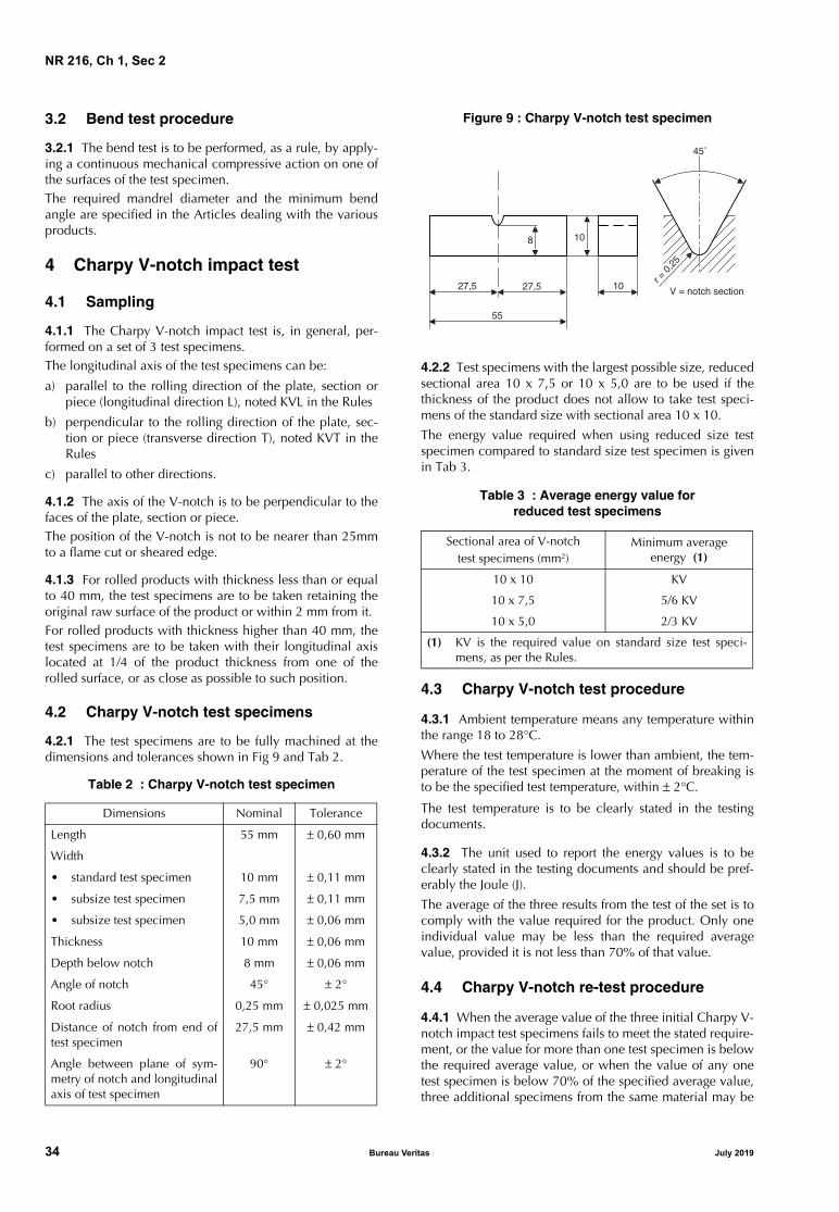
3.2.1 The bend test is to be performed, as a rule, by apply-ing a continuous mechanical compressive action on one ofthe surfaces of the test specimen.The required mandrel diameter and the minimum bendangle are specified in the Articles dealing with the variousproducts.
4 Charpy V-notch impact test
4.1 Sampling
4.1.1 The Charpy V-notch impact test is, in general, per-formed on a set of 3 test specimens.The longitudinal axis of the test specimens can be:
a) parallel to the rolling direction of the plate, section orpiece (longitudinal direction L), noted KVL in the Rules
b) perpendicular to the rolling direction of the plate, sec-tion or piece (transverse direction T), noted KVT in theRules
c) parallel to other directions.
4.1.2 The axis of the V-notch is to be perpendicular to thefaces of the plate, section or piece.The position of the V-notch is not to be nearer than 25mmto a flame cut or sheared edge.
4.1.3 For rolled products with thickness less than or equalto 40 mm, the test specimens are to be taken retaining theoriginal raw surface of the product or within 2 mm from it.For rolled products with thickness higher than 40 mm, thetest specimens are to be taken with their longitudinal axislocated at 1/4 of the product thickness from one of therolled surface, or as close as possible to such position.
4.2 Charpy V-notch test specimens
4.2.1 The test specimens are to be fully machined at thedimensions and tolerances shown in Fig 9 and Tab 2.
Table 2 : Charpy V-notch test specimen
Figure 9 : Charpy V-notch test specimen
4.2.2 Test specimens with the largest possible size, reducedsectional area 10 x 7,5 or 10 x 5,0 are to be used if thethickness of the product does not allow to take test speci-mens of the standard size with sectional area 10 x 10.
The energy value required when using reduced size testspecimen compared to standard size test specimen is givenin Tab 3.
Table 3 : Average energy value forreduced test specimens
4.3 Charpy V-notch test procedure
4.3.1 Ambient temperature means any temperature withinthe range 18 to 28°C.
Where the test temperature is lower than ambient, the tem-perature of the test specimen at the moment of breaking isto be the specified test temperature, within ± 2°C.
The test temperature is to be clearly stated in the testingdocuments.
4.3.2 The unit used to report the energy values is to beclearly stated in the testing documents and should be pref-erably the Joule (J).
The average of the three results from the test of the set is tocomply with the value required for the product. Only oneindividual value may be less than the required averagevalue, provided it is not less than 70% of that value.
4.4 Charpy V-notch re-test procedure
4.4.1 When the average value of the three initial Charpy V-notch impact test specimens fails to meet the stated require-ment, or the value for more than one test specimen is belowthe required average value, or when the value of any onetest specimen is below 70% of the specified average value,three additional specimens from the same material may be
Dimensions Nominal Tolerance
Length 55 mm ± 0,60 mm
Width
• standard test specimen 10 mm ± 0,11 mm
• subsize test specimen 7,5 mm ± 0,11 mm
• subsize test specimen 5,0 mm ± 0,06 mm
Thickness 10 mm ± 0,06 mm
Depth below notch 8 mm ± 0,06 mm
Angle of notch 45° ± 2°
Root radius 0,25 mm ± 0,025 mm
Distance of notch from end oftest specimen
27,5 mm ± 0,42 mm
Angle between plane of sym-metry of notch and longitudinalaxis of test specimen
90° ± 2°
Sectional area of V-notchtest specimens (mm2)
Minimum average energy (1)
10 x 10 KV
10 x 7,5 5/6 KV
10 x 5,0 2/3 KV
(1) KV is the required value on standard size test speci-mens, as per the Rules.
8
27,5 27,5
10
10
55
45˚
V = notch sectionr =
0,2
5
34 Bureau Veritas July 2019

NR 216, Ch 1, Sec 2
tested and the results added to those previously obtained toform a new average. If this new average complies with therequirements and if not more than two individual results arelower than the required average and of these, not more thanone result is below 70% of the specified average value thepiece or batch (as applicable) may be accepted.
5 Drop weight test
5.1 Definition and test specimens dimensions
5.1.1 The drop weight test according to ASTM Standard E208 is used for determination of the NDT (nil ductility tran-sition) temperature.
The NDT is the maximum temperature where the dropweight test specimen breaks when tested according to theprovisions of the standard.
Drop weight test specimens have one of the followingdimensions (thickness by width by length, in mm3):
• type P1: 25 x 90 x 360
• type P2: 19 x 50 x 130
• type P3: 16 x 50 x 130.
5.1.2 The following apply, if not otherwise agreed:
a) the test specimen sides are to be saw-cut or machined(minimum 25 mm distance to flame-cut surface)
b) the machining of the sample to obtain the requiredthickness of the test specimen is to be carried out onlyon one surface; the opposite raw surface is to be main-tained
c) the specimens may be of any orientation, but the orien-tation is to be the same for all specimens.
6 Crack Tip Opening Displacement (CTOD) test
6.1 General
6.1.1 Unless otherwise agreed, the test is to be performedon test specimens of full thickness according to appropriatenational or international standards like BS 7448 Part 1:1991and ASTM E 1290.
7 Ductility tests for pipes and tubes
7.1 Flattening test
7.1.1 The test specimen consists of a ring cut withsmoothed ends perpendicular to the tube axis.
The length of the specimen is to be from 10 mm to 100 mm.
7.1.2 The test consists of compressing the test specimenbetween two rigid and parallel flat plates in a direction per-pendicular to its longitudinal axis; the plates are to coverthe whole test specimen after flattening.
It is to be continued until the distance Z between the twoplates, measured under load, reaches the value specified.
In the case of welded pipes or tubes, the test is to be carriedout with the weld seam positioned at 90° and at 0° to theflattening force.
After flattening, the test specimen is not to present anycracks or other flaws; however, small cracks at the ends maybe disregarded.
7.2 Drift expanding test
7.2.1 The test specimen consists of a tube section havingthe ends perpendicular to the tube axis; the edges of theend to be tested may be rounded by filing.
7.2.2 For metallic tubes, the length of the specimen isequal to 2 D, where D is the external diameter of the tube, ifthe angle of the drift is 30°, or equal to 1,5 D if the angle ofthe drift is 45° or 60°. The test piece may be shorter pro-vided that after testing the remaining cylindrical portion isnot less than 0,5D.
7.2.3 The rate of penetration of the mandrel shall notexceed 50 mm/min.
7.2.4 The test consists of flaring the end of the test speci-men at ambient temperature and symmetrically, by meansof a truncated-cone shaped mandrel of hardened steel hav-ing the included angle specified in [7.2.2] (see Fig 10).
The mandrel is to be lubricated but is not to be rotated inthe pipe during the test.
The mandrel penetration is to continue until the increase inexternal diameter of the end of the expanded zone reachesthe value specified in the requirements relevant to the vari-ous products.
The expanded zone of the test specimen is not to presentany cracks or other flaws.
Figure 10 : Drift expanding test
30˚ or 45˚ or 60˚ or 120˚
July 2019 Bureau Veritas 35

NR 216, Ch 1, Sec 2
7.3 Flanging test
7.3.1 The test specimen consists of a tube section cut withthe ends perpendicular to the tube axis; the edges of theend to be tested may be rounded by filing.
7.3.2 The length of the test specimen is equal to approxi-mately 1,5 times the external diameter of the tube. The testspecimen may be shorter provided that after testing theremaining cylindrical portion is not less than half the exter-nal diameter.
7.3.3 The test is carried out in two stages and consists ofsymmetrically forming a flange at one end of the test speci-men by means of a special mandrel of hardened steel; themandrel is to be lubricated but is not to be rotated in thetube during the test.
The rate of penetration of the forming tool shall not exceed50 mm/min.
During the first stage of flanging, the end of the test speci-men is expanded by means of a truncated-cone shapedmandrel having an included angle of 90°; the test is thencontinued during the second stage using a special formingmandrel to complete the flange.
The test is to be continued until the expanded zone forms aflange perpendicular to the longitudinal axis of the testspecimen, with an increase in the external diameter of theend of the test specimen not less than the value specified(see Fig 11).
The cylindrical and flanged portion of the test specimen isnot to present any cracks or other flaws.
After testing, the remaining cylindrical portion is to be notless than half the external diameter of the tube.
Figure 11 : Flanging test
7.4 Ring expanding test
7.4.1 The test specimen consists of a tube section cut withthe ends perpendicular to the tube axis and the lengthbetween 10 and 16 mm.
7.4.2 The rate of penetration of the mandrel shall notexceed 30 mm/s.
7.4.3 The test specimen is to be expanded to the prescribeddiameter or until fracture occurs (see Fig 12).
The expanded test specimen is not to reveal defects such ascracks, grooves or laminations and is to reach the pre-scribed expansion.
Figure 12 : Ring expanding test
7.5 Ring tensile test
7.5.1 The test specimen consists of a tube section withplain and smoothed ends cut perpendicular to the tube axisand with a length of about 15 mm.
7.5.2 The test specimen is to be drawn to fracture in a ten-sile testing machine by means of two mandrels havingdiameter equal to at least three times the wall thickness ofthe pipe.
The rate shall not exceed 5 mm/s.
In the case of welded pipes the weld seam is to be at 90° tothe direction of the tensile load.
The test specimen after fracture is not to reveal defects suchas cracks, grooves or laminations and is to show visibledeformation at the point of fracture.
7.6 Bend test on pipes and tubes
7.6.1 Where feasible, the test specimen consists of fullthickness strips not less than 40 mm in width (which may bemachined down to 20 mm width for large thickness pipes)cut perpendicular to the pipe axis.
The edges of the test specimen may be rounded to 1,5 mmradius.
The result is considered satisfactory if, after being bentthrough the required angle in the direction of the originalcurvature, the test specimen is free from cracks and lamina-tions; however, small cracks on the edges may be disre-garded.
7.6.2 For small diameter tubes, in general not exceeding50 mm, the test specimen consists of a tube section of suffi-cient length.
The test specimen is to be bent on a cylindrical mandrelwith appropriate procedures as stated below, depending onthe specification of the product:
a) on a mandrel having a diameter 12 times the nominaldiameter of the tube until an angle of 90° is reached
b) on a mandrel having a diameter 8 times the nominaldiameter of the tube, until an angle of 180° is reached.
The test specimen after bending is not to present any cracksor other flaws.
36 Bureau Veritas July 2019

NR 216, Ch 1, Sec 2
8 Other tests and checks
8.1 Strain age embrittlement test
8.1.1 The test is performed according to the followingrequirements:
a) the material is to be deformed, generally by compres-sion (in special cases, deformation under tension maybe permitted) until the required shortening (or elonga-tion) (usually 3%, 5% or 10%) is attained
b) the material is then to be heat treated in a furnace at250°C for 1/2 h unless otherwise agreed
c) Charpy impact test specimens are to be obtained fromthe strained and treated material and broken at the spec-ified temperature.
When the deformation is reached by lateral compression,the procedure of artificial aging described above may beapplied directly to the individual test specimens.
8.2 Macrographic and micrographic examinations
8.2.1 The following examinations may be required to beperformed as a random check for specific steel products:
a) macrographic examination for detection of sulphur seg-regations (sulphur print or “Baumann test”) according toISO 4968
b) evaluation of the primary austenitic grain size“McQuaid Ehn test” according to ASTM E 112 58 TStandards. For fine grained steels, the “fine grain” condi-tion is considered satisfied when the grain size is 5 orfiner.
Test methods according to other recognised standards maybe accepted by agreement with the Society.
8.2.2 The laboratory which carries out the examination isto issue a certificate of the results and photographic docu-mentation of typical zones is to be enclosed.
July 2019 Bureau Veritas 37

NR 216, Ch 1, Sec 2
38 Bureau Veritas July 2019

NR 216
Chapter 2
STEEL AND IRON PRODUCTS
SECTION 1 ROLLED STEEL PLATES, SECTIONS AND BARS
SECTION 2 STEEL PIPES, TUBES AND FITTINGS
SECTION 3 STEEL FORGINGS
SECTION 4 STEEL CASTINGS
SECTION 5 IRON CASTINGS
July 2019 Bureau Veritas 39

40 Bureau Veritas July 2019

NR 216, Ch 2, Sec 1
SECTION 1 ROLLED STEEL PLATES, SECTIONS AND BARS
1 General
1.1 Scope
1.1.1 The requirements of this Section apply to hot rolledplates, strips, sections and bars intended for hull, structuralapplications, boilers, pressure vessels and parts of machinery.
Article [1] specifies the requirements common to all theabove-mentioned steel products, while the appropriate spe-cific requirements are indicated in Articles [2] to [11].
1.2 Manufacture
1.2.1 Steel is to be manufactured by the electric furnace,basic oxygen or open hearth processes.
The use of other processes may be specially approved bythe Society.
1.2.2 The steel is to be cast in ingot moulds or by a contin-uous casting process.
Provision is to be made for sufficient discard such as toensure:
• at both ends of the ingots, the soundness of the material
• at the transitory zones of continuous casting material, ahomogeneous chemical composition along the longitu-dinal axis.
1.3 Approval
1.3.1 The manufacturing process is to be approved by theSociety for individual steelmakers, grade of steel and prod-ucts, as specified in the applicable Articles.
Provisions for the approval are given in the documentNR480 “Approval of the manufacturing process of metallicmaterials”.
1.3.2 Rolling mills without their own steelmaking have toensure that the slabs, blooms or ingots are supplied byworks approved by the Society.
1.3.3 It is the manufacturer’s responsibility to assure thateffective process and production controls in operation areadhered to within the manufacturing specifications. Wherecontrol imperfection inducing possible inferior quality ofproduct occurs, the manufacturer is to identify the causeand establish a countermeasure to prevent its recurrence.Also, the complete investigation report is to be submitted tothe surveyor. For further use, each affected piece is to betested to the Surveyor’s satisfaction. The frequency of testingfor subsequent products offered may be increased at the dis-cretion of the Society.
1.4 Quality of materials
1.4.1 All products are to have a workmanlike finish and tobe free from surface or internal defects which may impairtheir proper workability and use.
1.4.2 The responsibility for storage and maintenance of thedelivered product(s) with acceptable level of surface condi-tions rests with the manufacturer or shipyard before theproduct(s) are used in fabrication.
1.5 Visual, dimensional and non-destructive examinations
1.5.1 GeneralVisual, dimensional and, as appropriate, non-destructiveexaminations are to be performed by the manufacturer onthe materials supplied prior to delivery, as required.
The general provisions indicated in Ch 1, Sec 1, [3.6] andspecific requirements for the various products as specifiedin the relevant Articles of this Section apply.
Non-destructive examinations may be required by the Sur-veyor when deemed necessary.
1.5.2 Thickness tolerances of steel plates and wide flats
The tolerances on thickness of a given product are defined as:• minus tolerance is the lower limit of the acceptable
range below the nominal thickness • plus tolerance is the upper limit of the acceptable range
above the nominal thickness.
The requirements for minus tolerances on nominal thicknessare indicated in the Articles relevant to the various products.
The plus tolerance on nominal thickness are to be in accor-dance with a recognized national or international standardunless otherwise required by the Classification Society orpurchaser.
The tolerances on nominal thickness are not applicable toareas repaired by grinding.
The responsibility for verification and maintenance of theproduction within the required tolerances rests with themanufacturer. The Surveyor may require to witness somemeasurements.
1.5.3 Thickness measurementsAutomated method or manual method is applied to thethickness measurements.
At least two lines among Line 1, Line 2 or Line 3 as shownin Fig 1, are to be selected for the thickness measurementsand at least three points on each selected line as shown inFig 1 are to be selected for thickness measurement. If morethan three points are taken on each line the number ofpoints shall be equal on each line.
July 2019 Bureau Veritas 41
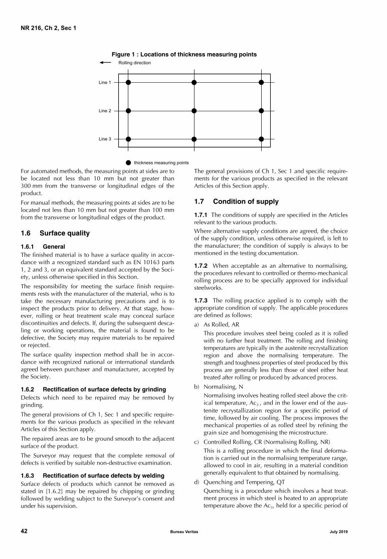
NR 216, Ch 2, Sec 1
Figure 1 : Locations of thickness measuring points
For automated methods, the measuring points at sides are tobe located not less than 10 mm but not greater than300 mm from the transverse or longitudinal edges of theproduct.
For manual methods, the measuring points at sides are to belocated not less than 10 mm but not greater than 100 mmfrom the transverse or longitudinal edges of the product.
1.6 Surface quality
1.6.1 GeneralThe finished material is to have a surface quality in accor-dance with a recognized standard such as EN 10163 parts1, 2 and 3, or an equivalent standard accepted by the Soci-ety, unless otherwise specified in this Section.
The responsibility for meeting the surface finish require-ments rests with the manufacturer of the material, who is totake the necessary manufacturing precautions and is toinspect the products prior to delivery. At that stage, how-ever, rolling or heat treatment scale may conceal surfacediscontinuities and defects. If, during the subsequent desca-ling or working operations, the material is found to bedefective, the Society may require materials to be repairedor rejected.
The surface quality inspection method shall be in accor-dance with recognized national or international standardsagreed between purchaser and manufacturer, accepted bythe Society.
1.6.2 Rectification of surface defects by grindingDefects which need to be repaired may be removed bygrinding.
The general provisions of Ch 1, Sec 1 and specific require-ments for the various products as specified in the relevantArticles of this Section apply.
The repaired areas are to be ground smooth to the adjacentsurface of the product.
The Surveyor may request that the complete removal ofdefects is verified by suitable non-destructive examination.
1.6.3 Rectification of surface defects by weldingSurface defects of products which cannot be removed asstated in [1.6.2] may be repaired by chipping or grindingfollowed by welding subject to the Surveyor’s consent andunder his supervision.
The general provisions of Ch 1, Sec 1 and specific require-ments for the various products as specified in the relevantArticles of this Section apply.
1.7 Condition of supply
1.7.1 The conditions of supply are specified in the Articlesrelevant to the various products.Where alternative supply conditions are agreed, the choiceof the supply condition, unless otherwise required, is left tothe manufacturer; the condition of supply is always to bementioned in the testing documentation.
1.7.2 When acceptable as an alternative to normalising,the procedures relevant to controlled or thermo-mechanicalrolling process are to be specially approved for individualsteelworks.
1.7.3 The rolling practice applied is to comply with theappropriate condition of supply. The applicable proceduresare defined as follows:
a) As Rolled, ARThis procedure involves steel being cooled as it is rolledwith no further heat treatment. The rolling and finishingtemperatures are typically in the austenite recrystallizationregion and above the normalising temperature. Thestrength and toughness properties of steel produced by thisprocess are generally less than those of steel either heattreated after rolling or produced by advanced process.
b) Normalising, NNormalising involves heating rolled steel above the crit-ical temperature, Ac3 , and in the lower end of the aus-tenite recrystallization region for a specific period oftime, followed by air cooling. The process improves themechanical properties of as rolled steel by refining thegrain size and homogenising the microstructure.
c) Controlled Rolling, CR (Normalising Rolling, NR)This is a rolling procedure in which the final deforma-tion is carried out in the normalising temperature range,allowed to cool in air, resulting in a material conditiongenerally equivalent to that obtained by normalising.
d) Quenching and Tempering, QTQuenching is a procedure which involves a heat treat-ment process in which steel is heated to an appropriatetemperature above the Ac3, held for a specific period of
��������� ���� ��� ������
���� �
���� �
���� �
������� �� ������
42 Bureau Veritas July 2019

NR 216, Ch 2, Sec 1
time, and then cooled with an appropriate coolant forthe purpose of hardening the microstructure. Temperingsubsequent to quenching is a process in which the steelis reheated to an appropriate temperature not higherthan the Ac1, maintained at that temperature for a spe-cific period of time to restore toughness properties byimproving the microstructure and reduce the residualstress caused by the quenching process.
Direct quenching after hot rolling, followed by temper-ing (DQ+T) is considered equivalent to conventionalquenching and tempering.
e) Thermo-Mechanical rolling, TM (Thermo-MechanicalControlled Processing, TMCP)
This is a procedure which involves the strict control ofboth the steel temperature and the rolling reduction.Generally a high proportion of the rolling reduction iscarried out close to the Ar3 temperature and mayinvolve the rolling in the dual phase temperature region.Unlike controlled rolling (normalising rolling), the prop-erties conferred by TM (TMCP) cannot be reproducedby subsequent normalising or other heat treatment.
The use of accelerated cooling on completion of TM-rolling may also be accepted, subject to the specialapproval of the Society. The same applies for the use oftempering after completion of the TM-rolling.
The generic designation Thermo-Mechanical rolling TMincludes Direct Quenching followed by tempering(TM + DQ) after TM-rolling.
f) Accelerated Cooling, AcC
Accelerated cooling is a process which aims to improvethe mechanical properties by controlled cooling withrates higher than air cooling immediately after the finalTM-rolling operation. Direct quenching is excludedfrom accelerated cooling.
The material properties conferred by TM and AcC can-not be reproduced by subsequent normalising or otherheat treatment.
1.8 Sampling and tests
1.8.1 General
All products are to be presented for testing in the final sup-ply condition in batches or rolled units as specified in theArticles relevant to the various products.
1.8.2 Sampling
The samples required for the preparation of test specimensare, in general, to be cut from:
a) the end of the plate or section corresponding to the topposition of the ingot, in the case of casting in ingot moulds
b) any end of the plate or section, where such products arerolled from blooms or billets manufactured by continu-ous casting, on the understanding that sufficient discardis taken from the transitory zones of the cast beginningand end
c) both the ends of the coil for plates fabricated in coils.
Samples are to be taken from the following positions:
• plates and flats having width ≥ 600 mm: at approxi-mately one quarter of the width from an edge (see Fig 2)
• flats having width < 600 mm, bulb flats and sections: atapproximately 1/3 of the width from an edge (see Fig 3,Fig 4 and Fig 5); alternatively, for channels, beams orbulb angles: on the web, at approximately 1/4 of thewidth from the centreline (see Fig 5)
• hollow sections: if rectangular, at approximately in thecentreline of one side; if circular, at any position alongthe circumference
• bars: at approximately 1/3 of the radius or half-diagonalfrom the outer surface; the axis of the sample should beat least 12 mm from the outer surface, except for barshaving diameter 25 mm or less, in which case the sam-ple is to be concentric with the bar (see Fig 6).
1.8.3 Preparation of test specimens
The test specimens are to be cut from the samples with theirprincipal axis parallel (longitudinal test) or perpendicular(transverse test) to the direction of rolling, as required in theArticles relevant to the various products.
For the preparation of test specimens and for the testing pro-cedures, reference is to be made to the applicable require-ments of Ch 1, Sec 2.
Figure 2 : Plates and flats
Figure 3 : Bulb flats
Figure 4 : Angles
1/4
W
W
1/3 W
W
W
1/3 W
July 2019 Bureau Veritas 43

NR 216, Ch 2, Sec 1
Figure 5 : Sections
Figure 6 : Bars
1.8.4 Tensile test
The results of the test are to comply with the values speci-fied in the Tables relevant to the various products.
If during the tensile test there is no marked yield stress ReH,the 0,2% proof stress Rp0,2, may be taken as an alternative.
1.8.5 Impact test
The average value is to comply with the minimum averagevalue specified in the Tables relevant to the various prod-ucts and only one individual value may be less than theaverage required, provided that it is not less than 70% of it.
The minimum average values are relevant to the standardspecimen 10 x 10 mm2.
For subsize specimen dimensions and requirements, refer-ence is to be made to Ch 1, Sec 2, [4.2.2].
1.8.6 Re-test procedures
Reference is made to Ch 1, Sec 1, [3.5].
For tensile re-test procedure, reference is made to Ch 1, Sec 2,[2.3].
For Charpy V-notch re-test procedure, reference is made toCh 1, Sec 2, [4.4].
1.9 Identification and marking
1.9.1 The manufacturer is to adopt a suitable system ofidentification which enables the product to be traced to itsoriginal cast.
1.9.2 All products which have been tested with satisfactoryresults are to be identified and marked, in addition to theSociety’s brand required in Ch 1, Sec 1, [4.1.3], with the fol-lowing indications:
a) manufacturer’s name or trade mark
b) identification mark for the grade of steel
c) cast number or other marking, which will enable thehistory of the fabrication of the product to be traced.
Different marking systems are to be agreed with the Society.
1.10 Documentation and certification
1.10.1 Information required
The testing documentation indicated in Ch 1, Sec 1, [4.2.1]is required and is to contain all the appropriate information.
The ladle analysis is to include the content of refining andalloying elements as applicable.
1.10.2 Inspection certificate
Before signing the Society’s inspection certificate or endors-ing the inspection certificate issued by the manufacturer(mill sheets), the Surveyor is to be provided by the manufac-turer with a written declaration, stating that the material hasbeen manufactured by a process accepted by the Society,complies with the applicable requirements and has beensatisfactorily tested in accordance with the Rules.
The following wording may be acceptable, either printed orstamped on the delivery documents, with the name of thesteel manufacturer and signed by one of his authorised rep-resentatives: “We hereby certify that the material has beenmade by an approved process and has been satisfactorilytested in accordance with the Society’s Rules”.
1.10.3 Casting and rolling in different works
When the steel is not produced at the works at which it isrolled, a certificate is to be supplied to the Surveyor at therolling mill stating the process by which it was manufac-tured, the name of the manufacturer who supplied it, thenumber of the cast from which it was made and the ladleanalysis. The Surveyor is to have access to the works atwhich the steel was produced.
2 Normal and higher strength steels for hull and other structural applications
2.1 Scope
2.1.1 The requirements of this Article apply to weldablenormal and higher strength steel hot rolled plates, wideflats, sections and bars intended for use in hull constructionand other structural applications.
A
1/4
B1/3 A
B
R
1/3 R
44 Bureau Veritas July 2019

NR 216, Ch 2, Sec 1
2.1.2 Provision is made for:
• plates and wide flats of all grades not exceeding100 mm in thickness
• sections and bars of all grades not exceeding 50 mm inthickness.
2.1.3 For thickness greater than the above, the require-ments may be modified, as appropriate, in the individualcases.
2.2 Steel grades
2.2.1 The steels are classed, on the basis of a minimum
yield strength level ReH (N/mm2), into normal strength
(ReH=235) and higher strength (32: ReH=315 - 36: ReH=355 -
40: ReH=390).
Normal strength steels are divided into four grades A, B, Dand E. For normal strength steels, the letters A, B, D and Emean impact properties at +20°C, 0°C, −20°C and −40°C,respectively.
Higher strength steels are divided into four grades identifiedby the letters AH, DH, EH and FH followed by a numberrelated to the yield strength level. For higher strength steels,the letters AH, DH, EH and FH mean impact properties at0°C, −20°C, −40°C and −60°C, respectively.
2.2.2 Steels differing in chemical composition, deoxidationpractice, conditions of supply and mechanical propertiesmay be accepted, subject to the special approval of theSociety. Such steels are to be given a special designation.
2.3 Manufacture
2.3.1 Approval
The manufacturers are to be approved by the Society andthe relevant requirements of [1.2] and [1.3]apply.
Provisions for the approval are given in NR480 “Approval ofthe manufacturing process of metallic materials”.
2.3.2 Deoxidation process
The method of deoxidation is specified in Tab 1 and Tab 2.
2.3.3 Rolling practice
Where CR (NR) and TM with or without AcC are applied,the programmed rolling schedules are to be submitted tothe Society at the time of the approval and are to be madeavailable when required by the attending Surveyor. On themanufacturer’s responsibility, the programmed rollingschedules are to be adhered to during the rolling operation(as per [1.3.3]). To this effect, the actual rolling records areto be reviewed by the manufacturer and, occasionally, bythe Surveyor.
When deviation from the programmed rolling schedulesoccurs, the manufacturer is to take further measures, to theSurveyor’s satisfaction, in accordance with [1.3.3].
Table 1 : Normal strength steels - Chemical composition and deoxidation practice
Steel grade A B D E
Deoxidation practice for thickness t (mm)
t ≤ 50 mm: any method except rimmed (1)t > 50 mm: killed
t ≤ 50 mm: any method except rimmed
t > 50 mm: killed
t ≤ 25 mm: killedt > 25 mm: killed and
fine grain treated
killed and fine grain treated
Chemical composition (%) (2) (3) (4)
C max (5) Mn min (5) Si max P max S max Al (acid soluble) min
0,21 (6)2,5 x C
0,500,0350,035
0,21 0,80 (7)
0,35 0,035 0,035
0,210,600,35
0,035 0,035
0,015 (8) (9)
0,180,700,35
0,035 0,035
0,015 (9)
(1) For sections up to a thickness of 12,5 mm, rimmed steel may be accepted subject to the special approval of the Society.(2) When any grade of steel is supplied in the thermo-mechanically rolled condition, variations in the specified chemical composi-
tion may be allowed or required by the Society and are to be stated at the approval.(3) The Society may limit the amount of residual elements which may have an adverse effect on the working and use of the steel,
e.g. copper and tin.(4) Where additions of any other element have been made as part of the steelmaking practice, the content is to be indicated in the
ladle analysis certificate.(5) C +1/6 Mn is not to exceed 0,40%.(6) Max. 0,23% for sections.(7) When Grade B steel is impact tested, the minimum manganese content may be reduced to 0,60%. (8) Al is required for thickness greater than 25 mm.(9) The total aluminum content may be determined instead of acid soluble content. In such cases the total aluminum content is to
be not less than 0,020%. Other suitable grain refining elements may be used subject to the special approval of the Society.
July 2019 Bureau Veritas 45

NR 216, Ch 2, Sec 1
Table 2 : Higher strength steels - Chemical composition and deoxidation practice
2.3.4 Thickness and tolerances (t ≥ 5mm)
The average thickness of plates and wide flats is defined asthe arithmetic mean of the measurements made in accor-dance with [1.5.2]. The average thickness of plates andwide flats is not to be less than the nominal thickness.
For plates and wide flats with thicknesses of 5 mm and over,a minus tolerance on nominal thickness of 0,3 mm is per-mitted.
Alternatively, Class C of ISO 7452-2013 or equivalentaccording to national or international standards may beapplied, in which case the requirements of this Articleabout average thickness and associated measurements neednot be applied.
Additionally, if Class C of ISO 7452-2013 is applied, it isrequired that the steel mill demonstrates to the satisfactionof the Society that the number of measurements and mea-surement distribution are appropriate to establish that themother plates produced are at or above the specified nomi-nal thickness.
For sections and bars with thicknesses of 5mm and over, theminus tolerance on nominal thickness is to be in accor-dance with the requirements of a recognized internationalor national standard.
The plus tolerance on nominal thickness are to be in accor-dance with a recognized national or international standardunless otherwise required by the Classification Society.
The tolerances on nominal thickness are not applicable toareas repaired by grinding as indicated in [2.4.3] which areto be in accordance with a recognized standard.
2.3.5 Thickness and tolerances (t < 5mm)The thickness tolerances for products with thicknessesbelow 5mm are to be in accordance with a national orinternational standard, e.g. Class B of ISO 7452-2013.However the minus tolerance shall not exceed 0.3mm.
2.4 Surface quality
2.4.1 General The general requirements for surface quality of [1.6] apply.
2.4.2 Acceptance criteriaa) Imperfections
Imperfections of a harmless nature, for example pitting,rolled-in scale, indentations, roll marks, scratches andgrooves, regarded as being inherent of the manufactur-ing process, are permissible irrespective of their number,provided the maximum permissible limits of Class A ofEN 10163-2 or limits specified in a recognized equiva-lent standard accepted by the Society, are not exceeded
Steel gradeAH32, DH32, EH32 AH36, DH36,
EH36 AH40, DH40, EH40FH32, FH36, FH40
Deoxidation practice killed and fine grain treated killed and fine grain treated
Chemical composition (%) (1) (5)
C max. Mn Si max. P max. S max. Al (acid soluble) min (3) (4) Nb (4) V (4) Ti max. (4) Cu max. Cr max. Ni max. Mo max. N max.
0,18 0,90 - 1,60 (2)
0,500,0350,0350,015
0,02 - 0,050,05 - 0,10
0,02 0,350,200,400,08
0,160,90 - 1,60
0,500,0250,0250,015
0,02 - 0,050,05 - 0,10
0,020,350,200,800,08
0,009 (0,012 if Al is present)
(1) Alloying elements other than those listed above or exceeding the specified limits may be accepted by the Society when pro-posed by the steelmaker at the time of approval and their content is to be indicated in the ladle analysis.
(2) Up to a thickness of 12,5 mm, the minimum manganese content may be reduced to 0,70.(3) The total aluminium content may be determined instead of the acid soluble content. In such cases the total aluminium content
is to be not less than 0, 020%.(4) The steel is to contain aluminium, niobium, vanadium or other suitable grain refining elements, either singly or in any combina-
tion. When used singly, the steel is to contain the specified minimum content of the grain refining element. When used in com-bination, the specified minimum content of at least one grain refining element is applicable; the sum of Nb + V + Ti is not toexceed 0,12%.
(5) When any grade of higher strength steel is supplied in the thermo-mechanically rolled condition, variations in the specifiedchemical composition may be allowed or required by the Society and are to be stated at the approval.
46 Bureau Veritas July 2019

NR 216, Ch 2, Sec 1
and the remaining plate or wide flat thickness remainswithin the average allowable minus thickness tolerancespecified in [2.3.4] or [2.3.5]. Total affected area withimperfection not exceeding the specified limits are notto exceed 15% of the total surface area in question.
b) Defects
Affected areas with imperfections with a depth exceed-ing the limits of Class A of EN 10163-2 or the maximumpermissible limits specified in a recognized equivalentstandard accepted by the Society, shall be repaired irre-spective of their number.
Cracks, injurious surface flaws, shells (over lappingmaterial with non-metallic inclusion), sand patches,laminations and sharp edged seams (elongated defects)visually evident on surface and/or edge of plate are con-sidered defects, which would impair the end use of theproduct and which require rejection or repair, irrespec-tive of their size and number.
2.4.3 Rectification of surface defects by grinding
Surface defects may be removed by grinding as indicated in[1.6.2] provided that:
a) the nominal thickness will not be reduced by more than7% or 3 mm, whichever is the less
b) each single ground area does not exceed 0,25 m2
c) the total ground area does not exceed 2% of the totalsurface of the plate
d) adjacent repairs located at a distance less than theirmean width are considered as forming a single groundarea
e) in the case of ground areas lying opposite each other onboth surfaces of the plate, the resulting thickness is tosatisfy in any place the values indicated in item a).
Defects or unacceptable imperfections are to be completelyremoved by grinding and the remaining plate or wide flatthickness shall remain within the average allowable minusthickness tolerance specified in [2.3.4] or [2.3.5].
The ground areas shall be a smooth transition to the sur-rounding surface of the product. Complete elimination ofthe defect is to be verified by magnetic particle or by liquidpenetrant testing.
2.4.4 Rectification of surface defects by welding
Weld repair procedures and the method are to be reportedand be approved by the Society. Repair of defects such asunacceptable imperfections, cracks, shells or seams shall befollowed by magnetic particle or liquid penetrant testing.
Surface defects of products which cannot be removed asstated in [2.4.3] may be repaired by chipping or grindingfollowed by welding subject to the agreement of the Societyand provided that:
a) after removal of defects and weld preparation, the thick-ness of the piece is in no place reduced by more than20% with respect to the nominal thickness. For occa-sional defects with depths exceeding 20% of nominalthickness, special consideration at the Surveyor’s discre-tion will be necessary.
b) repair is carried out by an approved procedure and byqualified welders. The electrodes shall be of low hydro-gen type and shall be dried in accordance with themanufacturer’s requirements and protected againstrehumidification before and during welding.
c) no single welded area exceeds 0,125 m2 and the sum ofall welded areas does not exceed 2% of the total surfacearea.
d) The distance between two welded areas shall not be lessthan their average width.
e) If weld repair depth exceeds 3mm, UT may berequested by the Society. If required, UT shall be carriedout in accordance with an approved procedure.
2.4.5 The surface quality and condition requirementsherein are not applied to products in forms of bars andtubulars, which will be subject to manufacturer’s confor-mance standards.
2.5 Internal soundness
2.5.1 If plates and wide flats are ordered with ultrasonicinspection, this is to be made in accordance with anaccepted standard at the discretion of the ClassificationSociety.
2.5.2 Ultrasonic testing of plates intended for offshorestructural applications of first and special category asdefined in the Society’s Offshore Rules is required and is tobe performed in accordance with a recognized standard(e.g. EN 10160 or ASTM A 578) and an examination levelaccepted by the Society.
2.5.3 Verification of internal soundness is the responsibilityof the manufacturer. The acceptance of internal soundnessby the Society’s surveyor shall not absolve the manufacturerfrom this responsibility.
2.6 Condition of supply
2.6.1 The products are to be supplied in the condition indi-cated in Tab 5 and Tab 6 for normal strength steels and Tab 9and Tab 10 for higher strength steels.
The definition of the supply conditions is given in [1.7.3].
2.7 Chemical composition
2.7.1 General The chemical composition is determined by the manufac-turer on ladle samples (see Ch 1, Sec 1, [2.2.1]).
2.7.2 Normal strength steels The chemical composition is to comply with the require-ments specified in Tab 1.
2.7.3 Higher strength steelsThe chemical composition is to comply with the require-ments specified in Tab 2.
At the time of the approval of higher strength steels, anupper limit for carbon equivalent CEQ on the ladle analysismay be specified.
July 2019 Bureau Veritas 47

NR 216, Ch 2, Sec 1
Unless otherwise agreed, the value of CEQ is calculated bythe following formula:
For steel produced by thermo-mechanical rolling, CEQ is tocomply with the requirements of Tab 3.
Table 3 : Carbon equivalent for higher strength steels up to 100 mm in thickness produced by TM process
As an alternative to CEQ, at the discretion of the Society, thecold cracking susceptibility Pcm may be used for evaluatingthe weldability.
Pcm is given by the following formula and an upper limitmay be agreed at the time of the approval of the steel:
When a limit of CEQ and Pcm is required, the relevant val-ues are to be stated by the manufacturer and included in thetesting documentation for each cast.
2.8 Mechanical properties
2.8.1 Normal strength steels
The mechanical properties are indicated in Tab 4.
The number of impact tests to be performed is indicated inTab 5 for plates and wide flats and Tab 6 for sections andbars.
Table 4 : Normal strength steels - Mechanical properties
Table 5 : Normal strength plates and wide flats - Condition of supply and number of impact tests
Steel grade
Carbon equivalentCEQ max. (%) (1)
t ≤ 50 50 < t ≤ 100
AH32, DH32, EH32, FH32AH36, DH36, EH36, FH36AH40, DH40, EH40, FH40
0,360,380,40
0,380,400,42
t = thickness (mm)
(1) More stringent carbon equivalent limits may be agreedbetween the manufacturer and the shipbuilder in indi-vidual cases.
CEQ C Mn6--------- Cr Mo V+ +
5-------------------------------- Ni Cu+
15--------------------- %+ + +=
Pcm C Si30------ Mn
20--------- Cu
20------- Ni
60------ Cr
20------ Mo
15--------- V
10------ 5B %+ + + + + + + +=
Steel grade
Yield stress ReH
(N/mm2) min.
Tensilestrength
Rm
(N/mm2)
El. A5 (%) min
(1)
Average impact energy (J) minKVL longitudinal - KVT transverse - t = thickness (mm)
Test temp (°C)
t ≤ 50 50 < t ≤ 70 70 < t ≤ 100
KVL KVT KVL KVT KVL KVT
A 235 400/520 (2) 22 +20 34 24 41 27
B 235 400/520 22 0 27 20 34 24 41 27
D 235 400/520 22 −20 27 20 34 24 41 27
E 235 400/520 22 −40 27 20 34 24 41 27
(1) El.: elongation. For full thickness flat tensile test specimens with a width of 25 mm and a gauge length of 200mm, the elonga-tion is to comply with the minimum values given for strength level 32 in Tab 8.
(2) For sections in grade A of all thicknesses, the upper limit for the specified tensile stress range may be exceeded up to a maxi-mum of 540 N/mm2.
Steel grade
Condition of supply (1)Batch for impact tests in tons () for thickness t (mm) (2)
t ≤ 25 25 < t < 35 35 ≤ t ≤ 50 50 < t ≤ 100
A A(−) (N,TM)(−), NR(50), AR*(50) (3)
B A (−) (4) A(50) (N,TM)(50), NR(25), AR*(25)
D A(50) (N,NR,TM)(50) (N,TM)(50), NR(25)
E N or TM (each piece)
(1) Abbreviations:A : Any N : Normalised Condition (heat treatment) NR : Normalising Rolled Condition as an alternative to Normalising TM : Thermo-Mechanical Rolling AR* : As Rolled Condition subject to the special approval of the Society.
(2) One set of impact tests is to be taken from each batch of the weight in tons specified in brackets (), from each fraction thereof orfrom each piece as indicated. When impact tests are not required the indication is (−).
(3) Charpy V-notch tests are generally not required for fine grained grade A products over 50 mm thick N or TM; when required,the rate is at the Society’s discretion.
(4) Charpy V-notch tests are generally not required for Grade B steel with thickness of 25 mm or less; when required, the rate is atthe Society’s discretion.
48 Bureau Veritas July 2019

NR 216, Ch 2, Sec 1
Table 6 : Normal strength sections and bars - Condition of supply and number of impact tests
2.8.2 Higher strength steels
The mechanical properties are indicated in Tab 7.
The condition of supply and the number of impact tests tobe performed are indicated in Tab 9 for plates and wide flatsand Tab 10 for sections and bars.
2.9 Mechanical tests
2.9.1 General
Samples for mechanical tests are to be cut from the prod-ucts in the final supply condition.The tests are to be carriedout on pieces selected from batches or on individual piecesas required in [2.9.5] and [2.9.6].
2.9.2 Batch testing
All materials in the batch are to be from the same heat, ofthe same product type, in the same condition of supply andwithin the following ranges of thickness and mass:
a) difference between minimum and maximum thicknessesnot exceeding 10 mm
b) mass not exceeding 50 t.
For products of steel type A intended for secondary applica-tions, the batch composition may not be required to berestricted to material from the same heat, but in such casethe mass of the batch is not to exceed 25 t.
2.9.3 Individual testing
For tests on individual pieces the term piece means rolledunit as defined in Ch 1, Sec 1, [3.3.3].
2.9.4 Sampling
For plates and flats having width ≥ 600 mm, the specimensfor tensile test are to be taken in the transverse direction andthe specimens for the Charpy V-notch impact test in the lon-gitudinal direction (KVL).
In the other cases, the specimens are to be taken in the lon-gitudinal direction, unless otherwise required by or agreedwith the Society.
The impact test requirements specified on transverse speci-mens (KVT) are to be guaranteed by the manufacturer andrandom checks may be required by the Society.
Generally, impact tests are not required when the nominalproduct thickness is less than 6 mm.
For plates fabricated in coils, the tensile and impact testsrequired are to be duplicated on specimens taken fromsamples cut at both ends of the coil.
Sampling positions are indicated in [1.8.2].
Additional through thickness tests may be required for spe-cial applications and are to be carried out according to therequirements of Article [11].
2.9.5 Number of tensile tests
One tensile test is to be carried out from one piece for eachbatch presented or fraction thereof.
In general the specimen is to be taken from a piece selectedin the batch among those with the highest thickness.
2.9.6 Number of impact tests
The number of sets of impact tests required is indicated inTab 5 and Tab 6 for normal strength products and Tab 9 andTab 10 for higher strength products.
When testing is by batches, the specimens are to be takenfrom a piece selected among those of the batch having thehighest thickness.
Steel grade
Condition of supply (1)Batch for impact tests in tons () for thickness t (mm) (2)
t ≤ 25 25 < t ≤ 35 35 < t ≤ 50
A A (−)
B A (−) (3) A (50)
D A (50) N(50), NR(50), TM(50), AR*(25)
E N(25), TM(25), AR*(15), NR*(15)
(1) Abbreviations:A : Any N : Normalised Condition (heat treatment) NR : Normalising Rolled Condition as an alternative to Normalising TM : Thermo-Mechanical Rolling AR* : As Rolled Condition subject to the special approval of the SocietyNR* : Normalising Rolled Condition subject to the special approval of the Society.
(2) One set of impact tests is to be taken from each batch of the weight in tons specified in brackets () or fraction thereof. Whenimpact tests are not required, the indication is (−).
(3) Charpy V-notch impact tests are generally not required for grade B steel with thickness of 25 mm or less.
July 2019 Bureau Veritas 49
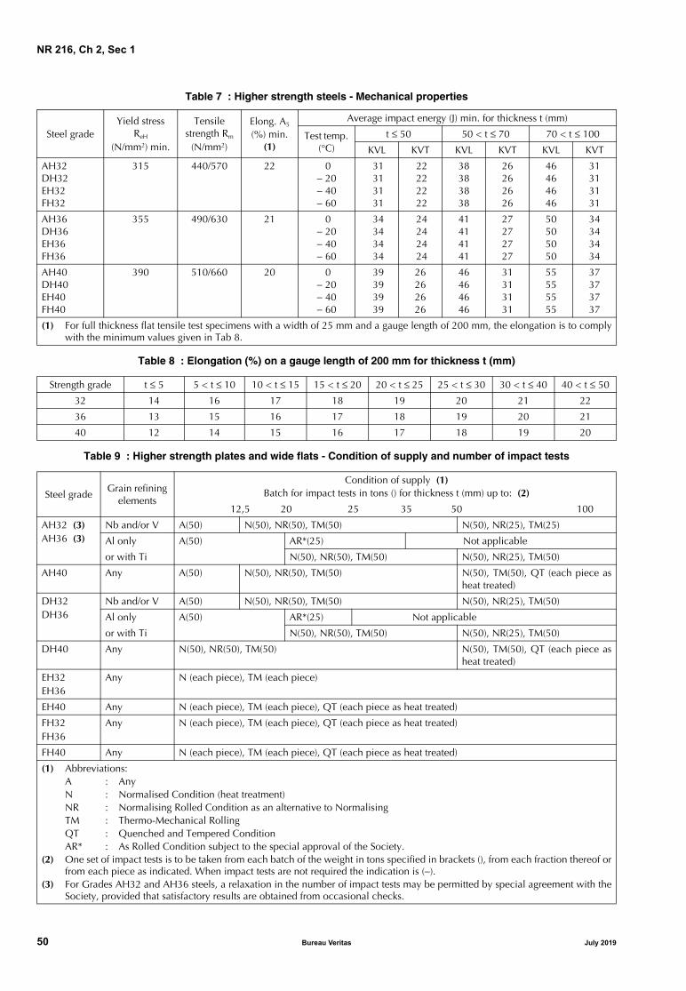
NR 216, Ch 2, Sec 1
Table 7 : Higher strength steels - Mechanical properties
Table 8 : Elongation (%) on a gauge length of 200 mm for thickness t (mm)
Table 9 : Higher strength plates and wide flats - Condition of supply and number of impact tests
Steel gradeYield stress
ReH
(N/mm2) min.
Tensile strength Rm
(N/mm2)
Elong. A5 (%) min.
(1)
Average impact energy (J) min. for thickness t (mm)
Test temp. (°C)
t ≤ 50 50 < t ≤ 70 70 < t ≤ 100
KVL KVT KVL KVT KVL KVT
AH32DH32EH32FH32
315 440/570 22 0− 20− 40− 60
31 31 31 31
22 22 22 22
38383838
26262626
46464646
31313131
AH36DH36EH36FH36
355 490/630 21 0− 20− 40− 60
34 34 34 34
24 24 24 24
41414141
27272727
50505050
34343434
AH40DH40EH40FH40
390 510/660 20 0− 20− 40− 60
39 39 39 39
26262626
46464646
31313131
55555555
37373737
(1) For full thickness flat tensile test specimens with a width of 25 mm and a gauge length of 200 mm, the elongation is to complywith the minimum values given in Tab 8.
Strength grade t ≤ 5 5 < t ≤ 10 10 < t ≤ 15 15 < t ≤ 20 20 < t ≤ 25 25 < t ≤ 30 30 < t ≤ 40 40 < t ≤ 50
32 14 16 17 18 19 20 21 22
36 13 15 16 17 18 19 20 21
40 12 14 15 16 17 18 19 20
Steel gradeGrain refining
elements
Condition of supply (1) Batch for impact tests in tons () for thickness t (mm) up to: (2)
12,5 20 25 35 50 100
AH32 (3)AH36 (3)
Nb and/or V A(50) N(50), NR(50), TM(50) N(50), NR(25), TM(25)
Al only A(50) AR*(25) Not applicable
or with Ti N(50), NR(50), TM(50) N(50), NR(25), TM(50)
AH40 Any A(50) N(50), NR(50), TM(50) N(50), TM(50), QT (each piece asheat treated)
DH32DH36
Nb and/or V A(50) N(50), NR(50), TM(50) N(50), NR(25), TM(50)
Al only A(50) AR*(25) Not applicable
or with Ti N(50), NR(50), TM(50) N(50), NR(25), TM(50)
DH40 Any N(50), NR(50), TM(50) N(50), TM(50), QT (each piece asheat treated)
EH32 EH36
Any N (each piece), TM (each piece)
EH40 Any N (each piece), TM (each piece), QT (each piece as heat treated)
FH32FH36
Any N (each piece), TM (each piece), QT (each piece as heat treated)
FH40 Any N (each piece), TM (each piece), QT (each piece as heat treated)
(1) Abbreviations:A : Any N : Normalised Condition (heat treatment) NR : Normalising Rolled Condition as an alternative to Normalising TM : Thermo-Mechanical Rolling QT : Quenched and Tempered Condition AR* : As Rolled Condition subject to the special approval of the Society.
(2) One set of impact tests is to be taken from each batch of the weight in tons specified in brackets (), from each fraction thereof orfrom each piece as indicated. When impact tests are not required the indication is (−).
(3) For Grades AH32 and AH36 steels, a relaxation in the number of impact tests may be permitted by special agreement with theSociety, provided that satisfactory results are obtained from occasional checks.
50 Bureau Veritas July 2019

NR 216, Ch 2, Sec 1
Table 10 : Higher strength sections and bars - Condition of supply and number of impact tests
The number of sets of specimens for the impact test, each ofthree specimens, summarised in the above-mentioned Tables,is to be in accordance with the following requirements:
a) one set is required for each batch of 50 tons, or fractionthereof for the following grades of steel, unless other-wise specified in b):• A, for products having thickness > 50 mm• B, for products having thickness > 25 mm• D, AH32, DH32, AH36, DH36, AH40, DH40
b) except for grade A, for products supplied subject to spe-cial approval in the as rolled condition (AR*), and forproducts with thickness higher than 50 mm supplied inthe controlled rolled condition (NR), the mass of thebatches for the purpose of impact tests is to be 25 t, or afraction thereof
c) one set of three impact test specimens is required for:• each piece for grades E and F in all strengths• each batch of 25 t or fraction thereof of sections of
grades E and F in all strengths
d) when, subject to special approval, sections of steelgrades E and F in all strengths other than 40 are suppliedin the as rolled (AR*) or controlled rolled (NR*) condi-tion, the mass of the batches for the purpose of impacttests is to be 15 t, or a fraction thereof.
Random checks of the impact values may be required at thediscretion of the Surveyor.
3 Normal and higher strength corrosion resistant steels for cargo oil tanks
3.1 Scope
3.1.1 The requirements of this Article apply to normal andhigher strength corrosion resistant steels when such steel isused as the alternative means of corrosion protection forcargo oil tanks as specified in the performance standardMSC.289(87) of Regulation 3-11, Part A-1, Chapter II-1 ofthe SOLAS Convention (Corrosion protection of cargo oiltanks of crude oil tankers).
3.1.2 Normal and higher strength corrosion resistant steelsare steels whose corrosion resistance performance in thebottom or top of the internal cargo oil tank is tested andapproved to satisfy the requirements in the performancestandard MSC.289 (87).
It is not intended that such steels be used for corrosion resis-tant applications in other areas of a vessel that are outsideof those specified in the performance standard MSC.289(87) of Regulation 3-11, Part A-1, Chapter II-1 of the SOLASConvention.
Steel gradeGrain refining
elements
Condition of supply (1)Batch for impact test in tons () for thickness t (mm) up to: (2)
12,5 20 50
AH32 (3)AH36 (3)
Nb and/or V A(50) N(50), NR(50), TM(50), AR*(25)
Al only or with Ti A(50) N(50), NR(50), TM(50), AR*(25)
AH40 Any A(50) N(50), NR(50), TM(50)
DH32 DH36
Nb and/or V A(50) N(50), NR(50), TM(50), AR*(25)
Al only or with Ti A(50) N(50), NR(50), TM(50), AR*(25)
DH40 Any N(50), NR(50), TM(50)
EH32 EH36
Any N(25), TM(25), AR*(15), NR*(15)
EH40 Any N(25), TM(25), QT(25)
FH32FH36
Any N(25), TM(25), QT(25), NR*(15)
FH40 Any N(25), TM(25), QT(25)
(1) Abbreviations:A : AnyN : Normalised Condition (heat treatment) NR : Normalising Rolled Condition as an alternative to Normalising TM : Thermo-Mechanical Rolling QT : Quenched and Tempered Condition AR* : As Rolled Condition subject to the special approval of the Society NR* : Normalising Rolled Condition subject to the special approval of the Society.
(2) One set of impact tests is to be taken from each batch of the weight in tons specified in brackets () or fraction thereof. (3) For Grades AH32 and AH36 steels, a relaxation in the number of impact tests for acceptance purposes may be permitted by
special agreement with the Society provided that satisfactory results are obtained from occasional checks.
July 2019 Bureau Veritas 51

NR 216, Ch 2, Sec 1
3.1.3 Provision is made for:
• plates and wide flats of all grades not exceeding 50 mmin thickness
• sections and bars of all grades not exceeding 50 mm inthickness.
3.2 Steel grades
3.2.1 The requirements of Article [3] are intended as a sup-plement to the requirements of Article [2], which specifythe steel grades for hull structures.
3.2.2 The corrosion resistant grade is designated accordingto its area of application with one of the following suffixes:
• lower surface of strength deck and surrounding struc-tures: RCU
• upper surface of inner bottom plating and surroundingstructures: RCB
• for both strength deck and inner bottom plating: RCW.
The suffix is given to any steel grade which has been testedaccording to the present Article and to the corrosion testingprocedure defined in the Appendix of the Annex to Perfor-mance Standard for Alternative Means of Corrosion Protec-tion for Cargo Oil Tanks of Crude Oil Tankers MSC.289(87).
3.3 Manufacture
3.3.1 Approval
Approval may be given for a steel grade for application inone of the following areas of cargo oil tank:
• lower surface of strength deck and surrounding struc-tures
• upper surface of inner bottom plating and surroundingstructures
• for both strength deck and inner bottom plating.
The requirements of [1.2] and [1.3] apply.
Provisions for the approval are given in NR480 “Approval ofthe manufacturing process of metallic materials”.
3.4 Chemical composition
3.4.1 The chemical composition of samples taken fromeach ladle of each cast is to be determined by the manufac-turer and is to be in accordance with the appropriaterequirements of [2.7].
The weight percentage of each element added or intention-ally controlled for improving corrosion resistance is to bedetermined and is to be in compliance with the approvedsteel grade specification.
Carbon equivalent requirements are to be in accordancewith [2.7], as applicable.
3.5 Marking
3.5.1 In addition to the requirements of [1.9], the appropri-ate suffix RCU, RCB or RCW is to be marked.
4 High strength steel and crack arrest steels plates for container ships structural applications
4.1 Scope
4.1.1 The requirements of this Article apply to hot rolledplates in high strength steel and crack arrest steel intendedfor longitudinal structural members in the upper deckregion of container ships, when required by the applicablerules.
4.1.2 Provision is made for plates not exceeding 100 mm inthickness.
4.2 Steel grades
4.2.1 The crack arrest steels are classed into three groups,on the basis of a minimum yield strength level ReH, inN/mm2 (36: ReH = 355; 40: ReH = 390; 47: ReH = 460).
Each group is further subdivided into two grades EH and FHbased of the impact test temperature. The letters EH and FHmean impact properties at −40°C and −60°C, respectively.
The suffix CAS (for Crack Arrest Steel) is added to the grade.
High strength steel grade EH47 belongs to the minimumyield strength level ReH = 460 N/mm2.
4.3 Manufacture
4.3.1 ApprovalThe manufacturers are to be approved by the Society andthe relevant requirements of [1.2] and [1.3] apply.
Provisions for the approval are given in NR480 “Approval ofthe manufacturing process of metallic materials”.
Approval program for steel grade EH47(without suffix CAS)is to be based on the program for the steel grade EH40.
4.3.2 Deoxidation processThe steel is to be killed and fine grain treated.
4.3.3 Rolling practiceWhere CR (NR) and TM (with or without AcC) are applied,the programmed rolling schedules are to be submitted tothe Society at the time of the approval and are to be madeavailable when required by the attending Surveyor. On themanufacturer’s responsibility, the programmed rollingschedules are to be adhered to during the rolling operation,(as per [1.3.3]). To this effect, the actual rolling records areto be reviewed by the manufacturer and, occasionally, bythe Surveyor.
When deviation from the programmed rolling schedulesoccurs, the manufacturer is to take further measures, to theSurveyor's satisfaction, in accordance with [1.3.3].
4.3.4 Thickness tolerances and surface conditionUnless otherwise agreed or specially required, the require-ments for tolerances on nominal thickness, surface condi-tion and rectification of surface defects are indicated in[2.3.4] or [2.3.5] and [2.4].
52 Bureau Veritas July 2019

NR 216, Ch 2, Sec 1
Table 11 : Plates - Condition of supply and number of impact tests
4.4 Condition of supply
4.4.1 The plates are to be supplied in the condition indi-cated in Tab 11.
The definition of the supply conditions is given in [1.7.3].
4.5 Chemical composition
4.5.1 The manufacturer is to submit a specification of thechemical composition of the high strength steel and crackarrest steel grades, which is to be approved by the Society.
The approved specification is also to include the alloyingand grain refining elements, the maximum Carbon equiva-lent CEQ and the maximum Pcm value (cold cracking sus-ceptibility index), agreed during the initial approval tests.
Unless otherwise agreed, the value of CEQ is calculated bythe following formula:
The Pcm value is to be calculated from the ladle analysis inaccordance with the following formula:
The alloying and grain refining elements, CEQ and Pcmvalue, as applicable, are to be stated by the steelmaker andincluded in the testing documentation for each cast.
4.5.2 The chemical composition on ladle analysis is tocomply with the requirements specified in the approvedspecification.
4.5.3 For steel produced by thermo-mechanical rolling, CEQ
and Pcm value are to comply with the requirement of Tab 12.
4.6 Mechanical properties
4.6.1 The mechanical properties are indicated in Tab 13.
The condition of supply and the number of impact tests tobe performed are indicated in Tab 11.
4.7 Mechanical tests
4.7.1 GeneralSamples for mechanical tests are to be cut from the prod-ucts in the final supply condition. The tests are to be carriedout on individual pieces as required in [4.7.4] and [4.7.5].
4.7.2 Individual testingThe term piece means rolled unit as defined in Ch 1, Sec 1,[3.3.3].
4.7.3 SamplingThe specimens for tensile test are to be taken in the trans-verse direction and the specimens for the Charpy V-notchimpact test in the longitudinal direction (KVL).
The impact test requirements specified on transverse speci-mens (KVT) are to be guaranteed by the manufacturer andrandom checks may be required by the Society.
Generally, impact tests are not required when the nominalproduct thickness is less than 6 mm.
Sampling positions are indicated in [1.8.2].
Additional through thickness tests may be required for spe-cial applications and are to be carried out according to therequirements of Article [11].
4.7.4 Number of tensile testsOne tensile test is to be carried out from each piece.
Table 12 : Carbon equivalent and Pcm value for high strength steel and crack arrest steels up to
100 mm thickness produced by TM process
Steel gradeGrain refining
elements Condition of supply (1)
EH36CAS Any N (each piece), TM (each piece)
EH40CAS Any N (each piece), TM (each piece), QT (each piece as heat treated)
EH47, EH47CAS Any TM (each piece)
FH36CASFH40CAS
Any N (each piece), TM (each piece), QT (each piece as heat treated)
(1) Abbreviations:N : Normalised Condition (heat treatment) TM : Thermo-Mechanical Rolling QT : Quenched and Tempered Condition.
CEQ C Mn6--------- Cr Mo V+ +
5-------------------------------- Ni Cu+
15--------------------- %+ + +=
Pcm C Si30------ Mn
20--------- Cu
20------- Ni
60------ Cr
20------ Mo
15--------- V
10------ 5B %+ + + + + + + +=
Steel grade
Carbon equivalentCEQ max. (%) (1)
Pcm value max. (%) (1)
t ≤ 50 50 < t ≤ 100 t ≤ 100
EH36CAS, FH36CAS 0,38 0,40 (2)
EH40CAS, FH40CAS 0,40 0,42 (2)
EH47, EH47CAS 0,49 0,22
t = thickness (mm)
(1) More stringent carbon equivalent or Pcm limits are tobe considered as per the approved specification
(2) As per the approved specification.
July 2019 Bureau Veritas 53

NR 216, Ch 2, Sec 1
Table 13 : Mechanical properties
4.7.5 Number of impact tests
The number of sets of impact tests required is indicated inTab 11.
One set of three impact test specimens is required for eachpiece of steel grades EH and FH in all strengths.
5 Extra high strength steels for welded structures
5.1 Scope
5.1.1 The requirements of this Article apply to hot rolled,fine grain, weldable extra high strength steel plates, wideflats, sections, bars and seamless tubulars, intended for usein marine and offshore structural applications. Theserequirements do not apply to steels intended for ship hullstructure.
5.1.2 Provision is made for plates, sections, bars and seam-less tubulars not exceeding thicknesses as specified in Tab 14.
5.1.3 For thickness greater than the above, the steel gradespecification may be accepted subject to the specialapproval of the Society.
5.2 Steel grades
5.2.1 The steels are classed into eight groups indicated byminimum yield strength levels ReH (N/mm²) 420, 460, 500,550, 620, 690, 890 and 960.
Each group is further subdivided into four grades A, D, Eand F based on the impact test temperature, except for yieldstrength levels 890 and 960 N/mm² for which grade F is notapplicable.
The letters A, D, E and F mean impact test at 0°C, −20°C, −40°Cand −60°C, respectively.
5.2.2 Steels differing in chemical composition, deoxidationpractice, conditions of supply and mechanical propertiesmay be accepted, subject to special approval of the Society.Such steels are to have the letter ”S” after the identificationmark [e.g.E620S].
5.3 Manufacture
5.3.1 Approval
The manufacturers are to be approved by the Society andthe relevant requirements of [1.2] and [1.3] apply.
Provisions for the approval are given in NR480 “Approval ofthe manufacturing process of metallic materials”.
5.3.2 Steelmaking process
Vacuum degassing shall be used for all extra high strengthsteels of this Article with enhanced through thickness prop-erties, and for steels grade with the minimum yield strengthReH = 690N/mm².
5.3.3 Deoxidation process and grain size
The steel is to be fully killed and fine grain treated.
The extra high strength steels shall have a fine grain struc-ture containing sufficient amounts of nitrogen binding ele-ments.
A fine grain structure has an equivalent index ≥ 6 deter-mined by micrographic examination in accordance withISO 643 or alternative test method.
5.3.4 Reduction ratio
The maximum thickness of slab, billet or bloom from thecontinuous casting process shall be at the manufacturer’sdiscretion.
Unless otherwise approved the total reduction ratio forproducts from slabs, billets, blooms or ingots is to be at least3:1.
5.3.5 Rolling practice
Where NR and TM (with or without AcC) are applied, theprogrammed rolling schedules are to be submitted to theSociety at the time of the approval and are to be made avail-able when required by the attending Surveyor. On the man-ufacturer’s responsibility, the programmed rolling schedulesare to be adhered to during the rolling operation (as per[1.3.3]). To this effect, the actual rolling records are to bereviewed by the manufacturer and, occasionally, by the Sur-veyor.
When deviation from the programmed rolling schedulesoccurs, the manufacturer is to take further measures, to theSurveyor’s satisfaction, in accordance with [1.3.3].
Steel gradeYield stress
ReH (N/mm2) min.
Tensile strength Rm
(N/mm2)
Elong. A5 (%) min.
Average impact energy (J) min. for thickness t (mm)
Test temp. (°C)
t ≤ 50 50 < t ≤ 70 70 < t ≤ 85 85 < t ≤ 100
KVL KVT KVL KVT KVL KVT KVL KVT
EH36CASFH36CAS
355 490/630 21− 40− 60
3434
2424
4141
2727
5050
3434
5050
3434
EH40CASFH40CAS
390 510/660 20− 40− 60
3939
2626
4646
3131
5555
3737
5555
3737
EH47EH47CAS
460 570/720 17 − 40 53 53 64 75
54 Bureau Veritas July 2019

NR 216, Ch 2, Sec 1
Table 14 : Maximum thickness limits
5.3.6 Thickness tolerances and surface condition
All materials are to be free from cracks, injurious surfaceflaws, injurious laminations and similar defects.
Unless otherwise agreed or specially required, toleranceson nominal thickness, surface condition and rectification ofsurface defects, the requirements are indicated in [2.3.4] or[2.3.5] and [2.4].
The surface quality inspection method shall be in accor-dance with recognized national or international standardsagreed between the purchaser and the manufacturer.
a) Welding repair procedures and the method for reportingrepairs are to be approved by the Society.
b) Where repair by grinding is carried out then the remain-ing plate thickness below ground area must be withinthe allowable under thickness tolerance.
Surface inspection is the responsibility of the manufacturer.The acceptance by the Surveyor of material later found tobe defective shall not absolve the manufacturer of thisresponsibility.
5.3.7 Non-destructive examination
Ultrasonic testing of plates intended for offshore structuralapplications of first and special category as defined in theSociety’s Offshore Rules is required and is to be performedin accordance with a recognised standard (e.g. EN 10160 orASTM A 578) and an examination level accepted by theSociety.
Verification of the internal soundness is the responsibility ofthe manufacturer. The acceptance by the Surveyor shall notabsolve the manufacturer of this responsibility.
5.4 Condition of supply
5.4.1 The products are to be supplied in Normalised (N)/Normalised Rolled (NR), Thermo-Mechanical controlledrolled (TM) or Quenched and Tempered (QT) condition asindicated in Tab 19.
The definition of supply condition is given in [1.7.3].
5.5 Chemical Composition
5.5.1 The chemical composition is to be determined by thesteelmaker in an adequately equipped and competentlystaffed laboratory. The method of sampling is to follow thatcarried out for the initial approval tests, either from the ladle,the tundish or the mould in the case of continuous casting.
The aim analysis is to comply with the approved specifica-tion. All elements listed in Tab 15 are to be reported.
The approved specification is to include the alloying, nitro-gen binding, grain refining and residual elements, the maxi-mum CEQ/CET and the maximum Pcm value (cold crackingsusceptibility index), agreed during the initial approval tests.
Unless otherwise agreed, the value of CEQ is calculated bythe following formula:
For steel grade with the minimum yield strength 460N/mm²,CET may be used instead of CEQ at the discretion of themanufacturer and is to be calculated using the followingformula:
For TM and QT steels with carbon content not more than0.12%, the cold cracking susceptibility Pcm for evaluatingweldability may be used instead of carbon equivalent CEQ
or CET at manufacturer’s discretion and is to be calculatedusing the following formula:
The alloying and grain refining elements, CEQ/CET and Pcmvalue, as applicable, are to be stated by the steelmaker andincluded in the testing documentation for each cast. CEQ/CET and Pcm value are to comply with the requirements ofTab 16, Tab 17 and Tab 18.
5.6 Mechanical properties
5.6.1 The mechanical properties are specified in Tab 19.
5.6.2 For plates and sections for applications, such as racksin offshore platforms etc; where the design requires that ten-sile properties are maintained through the thickness, adecrease in the minimum specified tensile properties is notpermitted with an increase in the thickness.
5.7 Mechanical tests
5.7.1 General
Samples for tests are to be cut from the products in the finalsupply condition. The tests are to be carried out on eachrolled unit as heat treated.
The definition of rolled unit is given in Ch 1, Sec 1, [3.3.3].
For continuously heat treated products, special samplingprocedures may be agreed at the Society’s discretion.
Delivery condition
Maximum thickness (mm)
Plates Sections Bars Tubulars
N 250 50 250 65
NR 150 (1)
TM 150 50 N.A. N.A.
QT 150 50 N.A. 50
N.A. = Not applicable.(1) The maximum thickness limits of sections, bars and
tubulars produced by NR process route are less thanthose manufactured by N route, and shall be agreedwith the Society.
CEQ C Mn6--------- Cr Mo V+ +
5-------------------------------- Ni Cu+
15--------------------- %+ + +=
CET C Mn Mo+10
------------------------ Cr Cu+20
-------------------- Ni40------ %+ + +=
Pcm C Si30------ Mn
20--------- Cu
20------- Ni
60------ Cr
20------ Mo
15--------- V
10------ 5B %+ + + + + + + +=
July 2019 Bureau Veritas 55

NR 216, Ch 2, Sec 1
Table 15 : Chemical composition
Table 16 : Maximum carbon equivalent CEQ /CET and maximum Pcm value for extra high strength steels produced by N/NR process
Delivery condition (1) N/NR TM QT
Steel grade A/D420 A/D460
E420 E460
A/D420 A/D460 A/D500 A/D550 A/D620 A/D690 A890
E/F420 E/F460 E/F500 E/F550 E/F620 E/F690 D/E890
A/D420 A/D460 A/D500 A/D550 A/D620 A/D690 A890 A960
E/F420 E/F460 E/F500 E/F550 E/F620 E/F690 D/E890 D/E960
Chemical composition (%) (2)
C max. Mn Si max. P max. (3) S max. (3) Al total min. (4) Nb max. (5) V max. (5) Ti max. (5) Cu max. Cr max. (5) Ni max. (6) Mo max. (5) N max. O ppm max. (7)
0,201,0 - 1,70
0,600,0300,0250,020,050,200,050,550,300,800,100,025
Not applicable
0,181,0 - 1,70
0,600,0250,0200,020,050,200,050,550,300,800,100,025
Not applicable
0,161,0 - 1,70
0,600,0250,0150,020,050,120,050,550,502,000,500,025
Not applicable
0,141,0 - 1,70
0,600,0200,0100,020,050,120,050,550,502,000,50
0,02550
0,181,700,80
0,0250,0150,0180,060,120,050,501,502,000,70
0,015Not applicable
0,181,700,80
0,0200,0100,0180,060,120,050,501,502,000,70
0,01530
(1) See [5.4] for definition of delivery conditions.(2) The chemical composition is to be determined by ladle analysis and shall meet the approved manufacturing specification at the
time approval. When boron is deliberated added for enhancement of hardenability of the steels, the maximum boron contentshall not be higher than 0,005%.
(3) For sections the P and S content can be 0,005% higher than the value specified in the table.(4) The total aluminium to nitrogen ratio shall be a minimum of 2:1. When other nitrogen binding elements are used, the minium
Al value and Al/N ratio do not apply. (5) Total Nb + V + Ti ≤ 0,26% and Mo + Cr ≤ 0,65%, not applicable for QT steels.(6) Higher Ni content may be agreed with the Society.(7) The requirement of maximum Oxygen content is only applicable to D890, E890, D960 and E960.
Steel gradeN/NR
CEQ (%) CET (%) Pcm (%)
Plates Sections Bars Tubulars
all allt ≤ 50mm
50 < t ≤ 100 mm
100 < t ≤ 250 mm
t ≤ 50mm
t or d ≤ 250 mm
t ≤ 65mm
A420, D420, E420, F420
0,46 0,48 0,52 0,47 0,53 0,47 N.A. N.A.
A460, D460, E460, F460
0,50 0,52 0,54 0,51 0,55 0,51 0,25 N.A.
N.A. = Not applicable
56 Bureau Veritas July 2019

NR 216, Ch 2, Sec 1
Table 17 : Maximum carbon equivalent CEQ /CET and maximum Pcm value for extra high strength steels produced by TM process
Table 18 : Maximum carbon equivalent CEQ /CET and maximum Pcm value for extra high strength steels produced by QT process
Steel gradeTM
CEQ (%) CET (%) Pcm (%)
Plates Sections
all allt ≤ 50mm
50 < t ≤ 100mm
100 < t ≤ 250mm
t ≤ 50mm
A420, D420,E420, F420
0,43 0,45 0,47 0,44 N.A. N.A.
A460, D460,E460, F460
0,45 0,47 0,48 0,46 0,30 0,23
A500, D500,E500, F500
0,46 0,48 0,50 N.A 0,32 0,24
A550, D550,E550, F550
0,48 0,50 0,54 N.A 0,34 0,25
A620, D620,E620, F620
0,50 0,52 N.A N.A. 0,34 0,26
A690, D690,E690, F690
0,56 N.A. N.A. N.A. 0,36 0,28
A890, D890,E890
0,60 N.A. N.A. N.A. 0,38 0,28
N.A. = Not applicable
Steel gradeQT
CEQ (%) CET (%) Pcm (%)
Plates Tubulars
all allt ≤ 50mm
50 < t ≤ 100mm
100 < t ≤ 250mm
t ≤ 65mm
A420, D420,E420, F420
0,45 0,47 0,49 0,46 N.A. N.A.
A460, D460,E460, F460
0,47 0,48 0,50 0,48 0,32 0,24
A500, D500,E500, F500
0,48 0,50 0,54 0,50 0,34 0,25
A550, D550,E550, F550
0,56 0,60 0,64 0,56 0,36 0,28
A620, D620,E620, F620
0,56 0,60 0,64 0,58 0,38 0,30
A690, D690,E690, F690
0,64 0,66 0,70 0,68 0,40 0,33
A890, D890,E890
0,68 0,75 N.A. N.A. 0,40 N.A.
A960, D960,E960
0,75 N.A. N.A. N.A. 0,40 N.A.
N.A. = Not applicable
July 2019 Bureau Veritas 57

NR 216, Ch 2, Sec 1
Table 19 : Mechanical properties
5.7.2 Sampling of tensile test specimen
The specimens for tensile test are to be taken with their lon-gitudinal axes transverse to the final rolling direction,except in the case of sections, bars, tubulars and flats hav-ing finished width ≤ 600mm, where the specimens may betaken in the longitudinal direction.
Full thickness flat tensile specimens are to be prepared insuch manner as to maintain the rolling scale at least at oneside. When the capacity of the test machine is exceeded bythe use of the full thickness specimen, sub-sized flat tensilespecimens representing either the full thickness or half ofthe product thickness retaining one rolled surface are to beused.
Steel grade
Delivery condition
(1)
Yield stress ReH (N/mm2) min. for thickness (mm) (2)
Tensile strength Rm (N/mm2)
for thickness (mm)
Elongation A5 (%) min. (3)
Average impact energy(J) min.
3 ≤ t ≤ 50 mm
50 < t ≤ 100 mm
100 < t ≤ 250 mm
3 ≤ t ≤ 100 mm
100 < t ≤ 250 mm
T LTest temp
(C°)KVT KVL
A420D420E420F420
N/NR orTM or QT
420 390 365 520-680 470-650 19 21
0−20−40−60
28 42
A460D460E460F460
N/NR orTM or QT
460 430 390 540-720 500-710 17 19
0−20−40−60
31 46
A500D500E500F500
TM or QT 500 480 440 590-770 540-720 17 19
0−20−40−60
33 50
A550D550E550F550
TM or QT 550 530 490 640-820 590-770 16 18
0−20−40−60
37 55
A620D620E620F620
TM or QT 620 580 560 700-890 650-830 15 17
0−20−40−60
41 62
A690D690E690F690
TM or QT 690 650 630 770-940 710-900 14 16
0−20−40−60
46 69
A890D890E890
TM or QT 890 830 N.A. 940-1100 N.A. 11 130
−20−40
46 69
A960D960E960
QT 960 N.A. N.A. 980-1150 N.A. 10 120
−20−40
46 69
(1) N: Normalising, NR: Normalising Rolling, TM: Thermo-Mechanical rolling, QT: Quenched and Tempered.(2) When ReH cannot be determined, the 0,2% proof stress (Rp0.2) value is to be determined. The material is considered to comply
with the requirement if either value meets or exceeds the specified minimum value of yield strength.(3) For full thickness flat test specimens having a width of 25mm and a gauge length of 200 mm, the elongation is to comply with
the minimum values given in Tab 20. The tabulated elongation minimum values specified in Tab 20 are the requirements fortesting specimens in transverse direction.
N.A. = Not applicable
58 Bureau Veritas July 2019

NR 216, Ch 2, Sec 1
Table 20 : Minimum elongation values for flat specimens 25 mm width and 200 mm gauge length
Alternatively, machined round test specimens may be used.The specimens are to be located at a position lying at a dis-tance t/4 from the surface and additionally at t/2 for thick-ness above 100mm or as near as possible to these positions.
Additional through thickness tests may be required for spe-cial application and are to be carried out according to therequirements of Article [11]. When required, through thick-ness tensile strength is not to be less than 80% of the speci-fied minimum tensile strength.
5.7.3 Sampling of impact test specimen
In the case of plates and wide flats having finished width ≥600 mm, the impact test specimens are to be taken withtheir axes transverse to the final rolling direction.
In other cases the specimens are to be taken in the longitu-dinal direction, unless otherwise required by or agreed withthe Society.
Sub-surface test specimens will be taken in such a way thatone side is not further away than 2mm from a rolled surface.
For products with a thickness higher than 50mm, impacttests shall be taken at the quarter thickness (t/4) location andmid-thickness (t/2) location.
Generally, impact tests are not required when the nominalproduct thickness is less than 6mm.
5.7.4 Number of tensile tests
Tensile test sample is to be randomly selected from eachbatch, as defined in Ch 1, Sec 1, [3.3.3] that is to be lessthan or equal to 25 tonnes, and to be from the same cast, inthe same delivery condition and of the same thickness.
5.7.5 Number of impact tests
a) For steel plates in N/NR or TM condition, test sample isto be taken from each piece.
b) For steel plates in QT condition, test sample is to betaken from each individually heat treated part thereof.
c) For sections, bars and tubulars, test sample is to betaken from each batch of 25 tonnes or fraction thereof.
If the mass of the finished material is greater than 25 tonnes,one set of tests from each 25 tonnes and/or fraction thereofis required (e.g. for consignment of 60 tonnes would require3 plates to be tested).
5.8 Marking
5.8.1 Each finished piece is to be clearly marked by themanufacturer as per [1.9] and with the following particulars:
a) Cast number/heat number, plate number or equivalentidentification mark
b) Delivery condition (N/NR, TM/TM+AcC/TM+DQ or QT)The entire markings are to be encircled with paint or other-wise marked so as to be easily recognized.
6 Steels for boilers and pressure vessels
6.1 Scope
6.1.1 The requirements of this Article apply to weldableferritic steel products (plates, flats, sections and bars)intended for boilers and pressure vessels.Provision is made for products with thickness up to 60 mmand impact properties at a temperature not lower than −20°C.
These requirements may also be applied to products withthickness above 60 mm subject to agreement with the Society.
6.1.2 Special requirements may be specified in the case ofapplications intended for dangerous substances or particu-larly severe service conditions.
6.1.3 In the case of applications involving the storage andtransport of liquefied gases, reference is to be made to Soci-ety’s Rules for the Classification of Steel Ships Pt D, Ch9 andto the International Code for the Construction and Equip-ment of Ships Carrying Liquefied Gases in Bulk (IGC Code).For gas fuelled ships, reference is to be made to SocietyRule Note NR 529, and, to the International Code of Safetyfor Ships using Gases or other Low-flash point Fuels (IGFCode).
Strength level (1)
Thickness t (mm)
t ≤ 10 10 < t ≤ 15 15 < t ≤ 20 20 < t ≤ 25 25 < t ≤ 40 40 < t ≤ 50 50 < t ≤ 70
420 11 13 14 15 16 17 18
460 11 12 13 14 15 16 17
500 10 11 12 13 14 15 16
550 10 11 12 13 14 15 16
620 9 11 12 12 13 14 15
690 9 (2) 10 (2) 11 (2) 11 12 13 14
(1) For strength levels 890 and 960, specimens which are not included in this table shall be proportional specimens with gaugelength of:
(2) For plates with thickness ≤ 20 mm and strength level 690, round specimen may be used instead of the flat tensile specimen.Theminimum elongation for testing specimen in transverse direction is 14%.
L0 5 65 So,=
July 2019 Bureau Veritas 59

NR 216, Ch 2, Sec 1
6.2 Steel grades
6.2.1 The requirements apply to carbon and carbon man-ganese steels and low alloy steels (Mo and Cr-Mo steels).
6.2.2 Carbon and carbon manganese steels are classed intofour groups indicated by the minimum ultimate tensilestrength Rm (N/mm2): 360, 410, 460 and 510.
Each group may be further subdivided into grades HA, HBand HD, as appropriate, based on the quality level andimpact properties.
The letters HA, HB and HD mean impact properties at+20°C, 0°C and −20°C, respectively.
6.2.3 Low alloy steels are designated according to thechemical composition into the grades 0,3Mo - 1Cr0,5Mo -2,25Cr1Mo.
Two types of 2,25Cr1Mo steel are specified in relation tothe heat treatment and consequent mechanical properties.
The figures mean the nominal percentage content of themain alloying elements.
6.2.4 In the case of liquefied gas carriers, plates and sec-tions intended for cargo tanks and process pressure vesselswith design temperature not lower than 0°C, the steelgrades with letters HB may be selected for thicknesses up to20mm included, and the steel grades with letters HD maybe selected for thicknesses from 20mm to 40mm included,as applicable.
6.3 Manufacture
6.3.1 Approval
Unless otherwise agreed by the Society, the manufacturersare to be approved and the relevant requirements of [1.2]and [1.3] apply.
Provisions for the approval are given in NR480 “Approval ofthe manufacturing process of metallic materials”.
6.3.2 Deoxidation process
The method of deoxidation is specified in Tab 21 and Tab 22.
6.3.3 Rolling practice
Where CR (NR) are applied, the programmed rolling sched-ules are to be submitted to the Society at the time of theapproval and are to be made available when required bythe attending Surveyor. On the manufacturer’s responsibil-ity, the programmed rolling schedules are to be adhered toduring the rolling operation (as per [1.3.3]). To this effect,the actual rolling records are to be reviewed by the manu-facturer and, occasionally, by the Surveyor.
When deviation from the programmed rolling schedulesoccurs, the manufacturer is to take further measures, to theSurveyor’s satisfaction, in accordance with [1.3.3].
6.3.4 Thickness tolerances
Minus tolerances on the nominal thickness are not normallypermitted.
6.3.5 Rectification of surface defects by grinding
Surface defects may generally be removed by grinding asindicated in [1.6.2], provided that the thickness, after grind-ing, is not less than the nominal thickness.
However the extent of repairs is to be agreed with the Sur-veyor. Where the thickness is reduced below the nominalthickness given in the approved plans, the possible accep-tance and the relevant conditions are subject to special con-sideration by the Society.
6.3.6 Rectification of surface defects by welding
Defects which cannot be removed by grinding may gener-ally be repaired by welding under the conditions given in[1.6.3], except that suitable heat treatment and non-destructive examination are always required after repair.
The purchaser is to be informed as to the extent and posi-tion of the repairs carried out on the individual plates.
6.4 Condition of supply
6.4.1 The products are to be supplied in the conditionsindicated in Tab 23 for carbon and carbon manganesesteels and Tab 24 for low alloy steels.
6.4.2 The products to be processed after supply by hotforming may also be supplied, where agreed, in the asrolled condition.
In such cases heat treatment is to be carried out after hotforming and provision for the mechanical tests indicated in[6.8.4] is to be made.
6.5 Chemical composition
6.5.1 The chemical composition on ladle analysis is tocomply with the requirements specified in Tab 21 for car-bon and carbon manganese steels and Tab 22 for low alloysteels and/or in the approved specification.
The approved specification is also to include the alloying andgrain refining elements (not specified in Tab 21 and Tab 22).
The relevant elements as applicable are to be stated by thesteelmaker and included in the testing documentation foreach cast.
For C and C-Mn steels, an upper limit for carbon equivalentCEQ on the ladle analysis may be specified at the time ofapproval of the individual steels.
60 Bureau Veritas July 2019

NR 216, Ch 2, Sec 1
Table 21 : Carbon and carbon manganese steels - Chemical composition
Table 22 : Low alloy steels - Chemical composition
Table 23 : Carbon and carbon manganese steels - Mechanical properties
Steel grade DeoxidationChemical composition (%) (1)
C max Mn Si P max S max Al tot. min. (1) Ni max
360HA not rimmed 0,16 ≥ 0,40 ≤ 0,35 0,030 0,030
360HB killed 0,16 0,40 - 1,20 0,10 - 0,35 0,030 0,030
360HD killed and fine grained 0,16 0,40 - 1,20 0,10 - 0,35 0,030 0,030 0,020
410HA not rimmed 0,20 ≥ 0,50 ≤ 0,35 0,030 0,030 0,30
410HB killed 0,20 0,50 - 1,40 0,10 - 0,35 0,030 0,030 0,30
410HD killed and fine grained 0,20 0,50 - 1,40 0,10 - 0,35 0,030 0,030 0,020 0,30
460HB killed 0,20 0,80 - 1,50 0,10 - 0,40 0,030 0,030 0,30
460HD killed and fine grained 0,20 0,80 - 1,50 0,10 - 0,40 0,030 0,030 0,020 0,30
510HB killed 0,22 0,90 - 1,60 0,10 - 0,50 0,030 0,025 0,30
510HD killed and fine grained 0,20 0,90 - 1,60 0,10 - 0,50 0,030 0,025 0,020 0,30
(1) Nb, V or Ti may be used for grain refining as a complete or partial substitute for Al. The grain refining elements are to be speci-fied at the time of approval; in general Nb and V are not to exceed 0,05 and 0,10%, respectively.Additional alloying elements are to be submitted for consideration and approval. Residual elements not intentionally added arenot to exceed the following limits:Cu ≤ 0,30%; Cr ≤ 0,25%; Mo ≤ 0,10%. Total: Ni + Cu + Cr + Mo ≤ 0,70%
Steel gradeDeoxidation
(2)
Chemical composition (%) (1)
C Mn Si P max S max Cr Mo
0,3Mo Si killed 0,12 - 0,20 0,40 - 0,90 0,10 - 0,35 0,030 0,030 ≤ 0,30 0,25-0,35
1Cr 0,5Mo Si killed 0,08 - 0,18 0,40 - 1,00 0,15 - 0,35 0,030 0,030 0,70-1,20 0,40-0,60
2,25Cr 1Mo Si killed 0,07 - 0,15 0,40 - 0,80 0,15 - 0,50 0,030 0,030 2,00-2,50 0,90-1,10
(1) Residual elements are not to exceed the following limits: Cu ≤ 0,30%, Ni ≤ 0,30%.(2) Aluminium total max 0,020% for all grades of steel. The aluminium content is to be mentioned in the ladle analysis certificate.
Steelgrade
Heattreatment
(1)
Yield stress ReH (N/mm2) min.for thickness (mm)
Tensilestrength
Rm
(N/mm2)
Elong. A5
(%) min.
Average impact energy (J)min.
t ≤ 16 16 < t ≤ 40 40 < t ≤ 60 Test temp (°C) KVT KVL
360HA
N or NR
215 205 195 360 - 480 25 + 20 27 41
360HB360HD
235 225 215 0
− 20
410HA
N or NR
245 235 225 410 - 530 23 + 20
410HB410HD
265 255 245 0
− 20
460HBN or NR
285 270 260 460 - 580 22 0
460HD 295 285 280 − 20
510HBN or NR
345 335 325 510 - 630 21 0
510HD 355 345 335 − 20
(1) N: Normalising - NR: Normalising Rolling. As an alternative to normalising, the as rolled condition may be accepted for sec-tions, subject to approval of individual steelmakers.
July 2019 Bureau Veritas 61

NR 216, Ch 2, Sec 1
Unless otherwise agreed, the value of CEQ is calculated bythe following formula:
Unless otherwise agreed, when a limit for CEQ is required,the relevant values are to be stated by the steel- maker andincluded in the testing documentation for each cast.
6.6 Mechanical properties
6.6.1 The mechanical properties are specified in Tab 23 forcarbon and carbon manganese steels and Tab 24 for lowalloy steels.
6.7 Mechanical properties at elevated temperatures
6.7.1 The values for the yield stress or 0,2% proof stress (Rp0,2)at temperatures of 100°C and higher are given in Tab 25.
The above Table are for design purposes only. Their verifica-tion is in general not required during the testing, unless fig-ures higher than those shown in the above Tables but inaccordance with recognised standards are proposed by thesteel manufacturer.
In such cases, the verification is required and the proce-dures detailed in [6.7.2] and [6.7.3] are to be followed.
Table 24 : Low alloy steels - Mechanical properties
Table 25 : Minimum proof stress (Rp0,2) values at elevated temperatures
CEQ C= Mn6--------- Cr Mo V+ +
5-------------------------------- Ni Cu+
15--------------------- %+ + +
Steel gradeHeat
treatment (1)
Yield stress ReH (N/mm2)min. for thickness (mm)
Tensile strength Rm
(N/mm2)
Elongation A5 (%) min. for thickness (mm)
Average impact energy (J) min.
at + 20°C
t ≤ 16 16 < t ≤ 40 40 < t ≤ 60 t ≤ 40 40 < t ≤ 60 KVT
0,3Mo N 275 270 260 430 - 600 24 23 31
1Cr 0,5Mo N + T 300 295 295 450 - 610 20 19
2,25Cr 0,5Mo N + T 295 285 275 520 - 670 18 18
N+T or Q+T 310 310 310 470 - 620
(1) N = Normalising; T = Tempering; Q = Quenching
Steelgrade
Thickness (mm)
Rp0,2 (N/mm2) at a temperature (°C) of:
100 150 200 250 300 350 400 450 500 550 600
360HA (1) ≤ 16> 16 ≤ 40> 40 ≤ 60
175171162
172169158
168162152
150144141
124124124
117117117
115115115
360HB (1)360HD (1)
≤ 16> 16 ≤ 40> 40 ≤ 60
204196179
185183172
165164159
145145145
127127127
116116116
110110110
410HA (1) ≤ 16> 16 ≤ 40> 40 ≤ 60
211201192
208198188
201191181
180171168
150150150
142142142
138138138
410HB (1)410HD (1)
≤ 16> 16 ≤ 40> 40 ≤ 60
235228215
216213204
194192188
171171171
152152152
141141141
134134134
460HB (1)460HD (1)
≤ 16> 16 ≤ 40> 40 ≤ 60
262260251
247242235
223220217
198198198
177177177
167167167
158158158
510HB (1)510HD (1)
≤ 60 290 270 255 235 215 200 180
0,3Mo ≤ 60 215 200 170 160 150 145 140
1Cr 0,5Mo ≤ 60 230 220 205 190 180 170 165
2,25Cr 1Mo ≤ 60 (2) ≤ 60 (3)
235265
230255
220235
210225
200215
190205
180195
(1) The values at Rp0,2 for temperatures ≤ 250°C are for guidance only(2) Normalised and tempered (3) Normalised and tempered or quenched and tempered
62 Bureau Veritas July 2019

NR 216, Ch 2, Sec 1
Table 26 : Average values for stress to rupture in 100000 hours (N/mm2)
6.7.2 When Rp0,2 is required to be verified, at least one ten-sile test for each cast is to be carried out at the agreed tem-perature.
The sample is to be cut from the thickest plate of the castand, if applicable, at the end of the plate that has shown thelowest figures in the tensile test at ambient temperature.
The sample is to be taken halfway between the edge and theaxis of the piece, and the axis of the test specimen is to belocated at one quarter of the thickness from one of therolled surfaces.
The dimensions of the specimens and the testing procedureare to be in accordance with the requirements of Ch 1, Sec2, [2.1] and Ch 1, Sec 2, [2.2.5], respectively.
The results of tests are to comply with the specified values.
6.7.3 As an alternative to the systematic verification of therequired Rp0,2 as in [6.7.2], it may be agreed with the indi-vidual steelmakers to carry out an adequate program of testson the normal production for each type of steel to beapproved.
For manufacturers and steel types approved on this basis,tensile tests at elevated temperatures are not generallyrequired during the routine testing of the material supplied;they may be required by the Society as a random check forthe confirmation of the approval.
6.7.4 For design purposes only, the estimated values of thestress to rupture in 100000 hours are given in Tab 26 forgroups of steels.
6.8 Mechanical tests
6.8.1 General Unless otherwise agreed (see [6.8.6]), samples for tests areto be cut from the products in the final supply conditions.
6.8.2 Samples from plates and wide flatsThe tests are to be carried out on each rolled unit as heattreated.
One sample is to be taken from one end of each rolled unitwhen the mass and the length do not exceed 5t and 15m,respectively.
Temperature (°C)Steel grade
360 - 410 460 - 510 0,3Mo 1Cr 0,5Mo 2,25Cr 1Mo
380 170 225
390 155 200
400 140 175
410 125 155
420 110 135
430 100 115
440 90 100
450 75 85 235 285 220
460 (60) (70) 205 250 205
470 (50) (60) 175 220 185
480 (40) (55) 145 190 170
490 (45) 120 160 150
500 (40) 100 135 135
510 80 120 120
520 65 95 105
530 50 80 90
540 60 75
550 50 65
560 40 55
570 30 50
580 45
590 (40)
600 (35)
Note 1: The values shown are estimated average values; the lower limit of the range is approximately 20% less than the average value. The values in brackets for some higher temperatures indicate that the steel is not suitable for continuous use at such tempera-tures.
July 2019 Bureau Veritas 63

NR 216, Ch 2, Sec 1
When either of these limits is exceeded, samples are to becut at both ends of each rolled unit.
The definition of rolled unit is given in Ch 1, Sec 1, [3.3.3].
6.8.3 Samples from sections and barsOne sample is to be taken from each batch homogeneousfor cast, section size and condition of supply. Each batch isto contain not more than 50 pieces and its total mass is notto exceed 10 t.
6.8.4 Sampling of test specimens
In the case of plates and wide flats having width ≥ 600mm,the tensile test and impact test specimens are to be taken inthe transverse direction.
In other cases the specimens are to be taken in the longitu-dinal direction, unless otherwise required by or agreed withthe Society.
6.8.5 Number of test specimensThe following test specimens are to be taken from eachsample:
a) 1 tensile test specimen (2 tests in the case of barsintended for tie rods)
b) 1 set of 3 Charpy V-notch impact test specimens (onlyfor grades HB and HD unless otherwise specified)
c) 1 tensile test specimen at elevated temperature, for eachcast, when required.
6.8.6 Material to be hot workedWhen for material to be hot worked after delivery, it is agreedthat the heat treatment required will be carried out by thepurchaser, the samples are to be submitted by the steelmakerto such treatment before the cutting of test specimens.
In particular cases (when the material is submitted to coldor hot working during fabrication), tests additional to theroutine testing may be required on samples in the final con-dition of the material after fabrication.
These may also include tests on material submitted to artifi-cial aging treatment as indicated in Ch 1, Sec 2, [8.1.1].
7 Ferritic steels for low temperature service
7.1 Scope
7.1.1 The requirement of this Article apply to ferritic steelproducts (plates, flats, sections and bars) intended for cargotanks, storage tanks, process pressure vessels and systemsfor liquefied gases and other pressure vessels in general,when impact properties at temperature lower than −20°Care required.
Provision is made for products with thickness up to 60mm.
The extension to higher thicknesses and relevant conditionsare subject to agreement with the Society.
7.1.2 Special requirements may be specified in the case ofapplications intended for dangerous substances or particu-larly severe service conditions.
7.1.3 In case of applications involving the storage andtransport of liquefied gases, reference is to be made to Soci-ety’s Rules for the Classification of Steel Ships Pt D, Ch 9and to the International Code for the Construction andEquipment of Ships Carrying Liquefied Gases in Bulk (IGCCode).For gas fuelled ships, reference is to be made to SocietyRule Note NR 529, and, to the International Code of Safetyfor Ships using Gases or other Low-flash point Fuels (IGFCode).
7.2 Steel grades
7.2.1 The requirements apply to carbon, carbon manga-nese and Ni steels.
7.2.2 The carbon and carbon manganese steels are classedinto six groups indicated by the minimum ultimate tensilestrength Rm (N/mm2): 390, 410, 460, 490, 510 and 550.
Each group may be further subdivided into three grades, LE,LF or LT, as appropriate, based on the quality level andimpact properties.
The letters LE and LF mean impact properties at −40°C and−60°C, respectively.The letters LT mean impact properties at temperaturebetween −55°C and −70°C, depending on the thickness.
7.2.3 Ni steels are designated according to the chemicalcomposition into the grades: 1,5Ni - 2.25Ni - 3,5Ni - 5Ni -9Ni. The figures mean the Ni nominal percentage content.
7.2.4 In the case of liquefied gas carriers, plates and sec-tions intended for cargo tanks, secondary barriers and pro-cess pressure vessels with design temperatures not lowerthan −50°C, the steel grades 390LT and 490LT may beselected as per Tab 30, as applicable.
7.2.5 In the case of liquefied gas carriers, plates and sec-tions intended for cargo tanks, secondary barriers and pro-cess pressure vessels with design temperatures lower than−55°C, nickel steels may be selected as per Tab 31,
depending on the design temperature, as applicable.
7.3 Manufacture
7.3.1 ApprovalThe manufacturers are to be approved by the Society andthe relevant requirements of [1.2] and [1.3] apply.
Provisions for the approval are given in NR480 “Approval ofthe manufacturing process of metallic materials”.
7.3.2 Deoxidation processThe steel is to be killed and fine grained.
7.3.3 Thickness tolerances For pressure vessels, minus tolerances on nominal thicknessare not normally permitted.
7.3.4 Surface conditionsFor repairs, the provisions of [6.3.5] and [6.3.6] apply.
Repairs by welding are not normally allowed on 5% or 9%nickel steels.
64 Bureau Veritas July 2019

NR 216, Ch 2, Sec 1
Table 27 : Carbon and carbon manganese steels - Chemical composition
Table 28 : Nickel steels - Chemical composition
Table 29 : Carbon and carbon manganese steels - Mechanical properties
Steel grade
Chemical composition (%) (1)
C max Mn Si P max S max Al tot min Ni max
410 LE 0,18 0,50 - 1,40 0,10 - 0,35 0,030 0,030 0,020 0,30
410 LF 0,16 0,50 - 1,40 0,10 - 0,35 0,030 0,030 0,020 0,80
460 LE 0,18 0,80 - 1,50 0,10 - 0,40 0,030 0,030 0,020 0,30
460 LF 0,16 0,80 - 1,50 0,10 - 0,40 0,030 0,030 0,020 0,80
510 LE 0,18 1,00 - 1,70 0,10 - 0,50 0,030 0,025 0,020 0,30
510 LF 0,16 1,00 - 1,70 0,10 - 0,50 0,030 0,025 0,020 0,80
550 LE 0,18 1,00 - 1,70 0,10 - 0,50 0,030 0,025 0,020 0,30
550 LF 0,16 1,00 - 1,70 0,10 - 0,50 0,030 0,025 0,020 0,80
390 LT 0,16 0,80 - 1,50 0,10 - 0,40 0,030 0,025 0,020 1,25
490 LT 0,16 1,00 - 1,70 0,10 - 0,50 0,030 0,025 0,020 1,25
(1) Nb, V or Ti may be used for grain refining as a complete or partial substitute for Al. The grain refining elements are to be speci-fied at the time of approval; in general Nb and V are not to exceed 0,05 and 0,10%, respectively. Additional alloying elementsare to be submitted for consideration and approval. Residual elements not intentionally added are not to exceed the followinglimits (%): Cu ≤ 0,30, Cr ≤ 0,15, Mo ≤ 0,10.
Steel gradeChemical composition (1) (2)
C max Mn Si max P max S max Ni Cr max Mo max
1,5 Ni 0,18 0,30 - 1,50 0,35 0,035 0,020 1,30 - 1,70 0,25 0,10
2,25 Ni 0,17 0,30 - 0,90 0,35 0,035 0,020 2,10 - 2,50 0,25 0,10
3,5 Ni 0,15 0,30 - 0,90 0,35 0,035 0,020 3,20 - 3,80 0,25 0,10
5,0 Ni 0,12 0,30 - 0,90 0,35 0,035 0,020 4,70 - 5,30 0,25 0,10
9,0 Ni 0,10 0,30 - 0,90 0,35 0,035 0,020 8,50 - 10,0 0,25 0,10
(1) Residual elements are not to exceed the following limits (%): Cu ≤ 0,35; V ≤ 0,05. Total Cr + Cu + Mo ≤ 0,50(2) Aluminium total not less than 0,020 for all grades of steels. The aluminium content is to be mentioned in the ladle analysis cer-
tificate.
Steelgrade
Yield stress ReH (N/mm2) min. for thickness t (mm) Tensile strength
Rm (N/mm2)Elong.
A5 (%) min
Average impact energy (J) min.
t ≤ 16 16 < t ≤ 40 40 < t ≤ 60 Temp (°C) KVT KVL
410 LE 265 255 245 410 - 530 23 − 40 27 41
410 LF 290 280 270 410 - 530 23 − 60 27 41
460 LE 295 285 270 460 - 580 22 − 40 27 41
460 LF 320 310 300 460 - 580 22 − 60 27 41
510 LE 355 345 335 510 - 630 21 − 40 27 41
510 LF 355 345 335 510 - 630 21 − 60 27 41
550 LE 390 380 375 550 - 670 20 − 40 27 41
550 LF 390 380 375 550 - 670 20 − 60 27 41
July 2019 Bureau Veritas 65

NR 216, Ch 2, Sec 1
7.4 Condition of supply
7.4.1 Unless otherwise accepted by the Society, carbonand carbon manganese products are to be supplied in nor-malised (N) condition.
Nickel steel products are to be supplied in the conditionsindicated in Tab 31.
7.4.2 The products to be processed after supply by hotworking may also be supplied, where agreed, in the asrolled condition.
In such cases heat treatment is to be carried out after form-ing and provision for the mechanical tests indicated in[6.8.6] is to be made.
7.5 Chemical composition
7.5.1 The chemical composition on ladle analysis is to com-ply with the requirements specified in Tab 27 and Tab 28and/or in the approved specification.
The approved specification is also to include the alloying andgrain refining elements (not specified in Tab 27 and Tab 28).
The content of the above elements, as applicable, is to bestated by the steelmaker for each heat and included in thetesting documentation.
For C and C-Mn steels, an upper limit for carbon equivalentCEQ on the ladle analysis may be specified at the time ofapproval of the individual steels.
Unless otherwise agreed, the value of CEQ is calculated bythe following formula:
Unless otherwise agreed, when a limit for CEQ is requiredthe relevant values are to be stated by the steelmaker andincluded in the testing documentation for each cast.
7.6 Mechanical properties
7.6.1 The products are to comply with the mechanicalproperties specified in Tab 29, Tab 30 and Tab 31.
7.7 Mechanical tests
7.7.1 General
Unless otherwise agreed in the case of materials to be hotworked after delivery [7.4.2], samples for tests are to be cutfrom the products in the final supply condition.
7.7.2 Samples from plates and wide flats
The tests are to be carried out on each rolled unit as heattreated.
One sample is to be taken from one end of each rolled unitwhen the mass and the length do not exceed 5t and 15m,respectively.
When either of these limits is exceeded, samples are to becut at both ends of each rolled unit.
The definition of rolled unit is given in Ch 1, Sec 1, [3.3.3].
7.7.3 Samples from sections and barsOne sample is to be taken from each batch homogeneousfor heat, section size and condition of supply.
Each batch is to contain not more than 50 pieces and itstotal mass is not to exceed 10 t.
7.7.4 Sampling of test specimensIn the case of plates and wide flats having width ≥ 600mm,the tensile test and impact test specimens are to be taken inthe transverse direction.
In other cases the specimens are to be taken in the longitu-dinal direction, unless otherwise required by or agreed withthe Society.
7.7.5 Number of test specimensThe following test specimens are to be taken from eachsample:
a) 1 tensile test specimen
b) 1 set of 3 Charpy V-notch impact test specimens
c) 2 or more drop weight test specimens, when required.
8 Steels for machinery
8.1 Scope
8.1.1 The requirements of this Article apply to carbon, car-bon manganese, low alloy and alloy rolled steel productsintended for use in the construction of structures and partsof machinery and equipment operating at ambient tempera-ture.
In the case of applications in low or high temperature pres-sure systems, reference is to be made to the applicablerequirements of Articles [7] and [6] respectively.
8.1.2 The products are grouped as follows, depending onthe application:
a) structural parts of deck equipment
b) welded machinery structures such as bedplates, crank-cases, frame entablatures or similar items
c) rolled products, such as bars for small shafts, pins, boltsor similar items, when, in the limit of diameters of250mm, they are accepted in lieu of forgings.
8.2 Steel grades and relevant properties
8.2.1 The type of steels covered by Articles [2], [6], [7] and[9] may be used as appropriate.
Chemical and mechanical properties are to comply with therequirements given therein.
For products having thickness exceeding the maximumthickness considered in the above-mentioned Articles, thefollowing deviations in mechanical properties are permitted:
• the minimum yield stress ReH required is reduced by 1%for every 5 mm thickness over the a.m. maximum
• the minimum elongation A5 min. required is reduced by1 unit for thickness over than the a.m. max up to 100 mmand by 2 units for thickness greater than 100 mm.
CEQ C= Mn6--------- Cr Mo V+ +
5-------------------------------- Ni Cu+
15--------------------- %+ + +
66 Bureau Veritas July 2019

NR 216, Ch 2, Sec 1
Table 30 : Carbon and carbon manganese steels - Mechanical properties
Table 31 : Nickel steels - Mechanical properties
8.3 Manufacture and condition of supply
8.3.1 Products intended for applications under [8.1.2] a)and [8.1.2] b) are to be manufactured and supplied as indi-cated in [2.3] and [2.6], [6.3] and [6.4], [7.3] and [7.4], asappropriate.For products intended for applications under [8.1.2] c), theapplicable requirements of Sec 3 apply; unless otherwiseagreed, a reduction ratio of 6:1 in respect of the originalingot is generally required.
8.3.2 For specific applications, ultrasonic examinations inaccordance with approved standards or procedures may berequired.
Rolled bars for shaft lines, used in lieu of forgings and havinga diameter higher than 150 mm, are to be submitted to non-destructive (ultrasonic and magnetoscopic) examinations.
8.3.3 Unless otherwise agreed or specially required, theminus tolerances on nominal thickness indicated in Tab 32apply to plates and wide flats.
Steelgrade
Yield stress ReH (N/mm2) min. for thickness t (mm) Tensile
strength Rm (N/mm2)
Elongation A5 (%) min
Average impact energy (J) min.
t ≤ 16 16 < t ≤ 40Thickness
(mm)Temp (°C) KVT KVL
390 LT 275 265 390 - 510 24 t ≤ 25 − 55 27 41
25 < t ≤ 30 − 60
30 < t ≤ 35 − 65
35 < t ≤ 40 − 70
490 LT 355 345 490 - 630 22 t ≤ 25 − 55 27 41
25 < t ≤ 30 − 60
30 < t ≤ 35 − 65
35 < t ≤ 40 − 70
Note 1: These requirements are applicable to products with thickness up to 40mm. For thicknesses exceeding 40 mm, the require-ments shall be agreed with the Society.
Steelgrade
Heat treatment (1)
Yield stress ReH (N/mm2) min.
Tensile strength Rm (N/mm2)
Elongation A5 (%) min.
Average impact energy (J) min.
Thickness (mm)
Temp (°C) KVT KVL
1,5 Ni N+T or Q+T 275 490 - 640 22 t ≤ 25 − 65 27 41
25 < t ≤ 30 − 70
30 < t ≤ 35 − 75
35 < t ≤ 40 − 80
2.25 Ni N+T or Q+T 275 490 - 640 22 t ≤ 25 − 70 27 41
25 < t ≤ 30 − 75
30 < t ≤ 35 − 80
35 < t ≤ 40 − 85
3,5 Ni N+T or Q+T 285 450 - 610 21 t ≤ 25 − 95 27 41
25 < t ≤ 30 − 100
30 < t ≤ 35 − 105
35 < t ≤ 40 − 110
5,0 Ni N+T or Q+T 390 540 - 740 21 t ≤ 25 − 110 27 41
25 < t ≤ 30 − 115
30 < t ≤ 35 − 120
35 < t ≤ 40 − 125
9,0 Ni N+N+T or Q+T 490 640 - 790 18 t ≤ 40 − 196 27 41
(1) N = normalising; T = tempering; Q = quenching.Note 1: These requirements are applicable to products with thickness up to 40mm. For thicknesses exceeding 40 mm, the require-ments shall be agreed with the Society.
July 2019 Bureau Veritas 67

NR 216, Ch 2, Sec 1
Table 32 : Minus tolerances on nominal thickness
8.4 Mechanical tests
8.4.1 For applications under [8.1.2] a) and [8.1.2] b), irre-spective of the grade of steel, the testing may be in batchesin accordance with the relevant requirements of Article [2].
One tensile test is to be carried out from one piece for eachbatch presented or fraction thereof.
Unless otherwise required, the impact tests may be omitted.
8.4.2 For applications under [8.1.2] c), the testing proce-dure is to be in accordance with the requirements of Sec 3,[1.7.4] relevant to forgings.
8.4.3 The results of tensile and impact tests are to complywith requirements of Articles [2], [6] and [7], [9], as appli-cable.
9 Stainless steel products
9.1 Scope
9.1.1 The requirements of this Article apply to austeniticand austenitic-ferritic (duplex) rolled stainless productsintended for use in construction of cargo tanks, storagetanks and pressure vessels for chemicals and limitedly to theaustenitic grades for liquefied gases.
9.1.2 Austenitic stainless steels are suitable for use both atelevated and low temperatures.
When austenitic stainless steels are proposed for use at ele-vated temperatures, details of chemical composition, heattreatment and mechanical properties are to be submitted forconsideration and approval.
Unless otherwise specified, austenitic-ferritic stainless steelsare in general suitable for design temperature between −20°Cand +275°C.
9.1.3 Stainless steel bars may be used for propeller shafts orsimilar applications under the conditions given in [8.1.2] c).
9.1.4 In cases of applications involving the storage andtransport of liquefied gases, reference is to be made to Soci-ety’s Rules for the Classification of Steel Ships Pt D, Ch 9
and to the International Code for the Construction andEquipment of Ships Carrying Liquefied Gases in Bulk (IGCCode).
For gas fuelled ships, reference is to be made to SocietyRule Note NR 529, and to the International Code of Safetyfor Ships using Gases or other Low-flash point Fuels (IGFCode).
9.2 Steel grades
9.2.1 The requirements apply to Cr-Ni austenitic and auste-nitic-ferritic stainless steels.Note 1: Reference is made for designation to the correspondingAISI grade.
Other stainless steel of martensitic types, in accordancewith international or national standards, may be acceptedfor specific applications such as in [9.1.3].
9.3 Manufacture
9.3.1 ApprovalUnless otherwise agreed, the manufacturers of steelintended for the construction of cargo tanks, storage tanksand pressure vessels for chemicals and liquefied gases areto be approved by the Society and the relevant require-ments of [1.2] and [1.3] apply.
Provisions for the approval are given in NR480 “Approval ofthe manufacturing process of metallic materials”.
9.3.2 Corrosion resistance The resistance of tank material to cargoes is under theresponsibility of the yard.
Justification of such resistance is to be submitted to theSociety.
9.3.3 Thickness tolerances With the exception of pressure vessels (see [6.3.4]), theminus tolerance on nominal thickness is to be 0,3 mm.
9.3.4 Surface conditionsSurface defects may be removed by grinding, provided thatthe plate thickness at the location of the ground zone is notless than the minimum thickness specified in [9.3.3].
Surface defects which cannot be removed by grinding maybe generally repaired under the conditions given in [2.4.4],as applicable.
9.4 Condition of supply
9.4.1 All materials are to be supplied in the solution treatedcondition.
9.5 Chemical composition
9.5.1 The chemical composition on ladle analysis is tocomply with the requirements specified in Tab 33.
9.6 Mechanical properties
9.6.1 The mechanical properties are specified in Tab 34.
Nominal thickness t (mm) Minus tolerance (mm)
3 ≤ t < 5 −0,3
5 ≤ t < 8 −0,4
8 ≤ t < 15 −0,5
15 ≤ t < 25 −0,6
25 ≤ t < 40 −0,7
40 ≤ t < 80 −0,9
80 ≤ t < 150 −1,1
150 ≤ t < 250 −1,2
t ≥250 −1,3
68 Bureau Veritas July 2019

NR 216, Ch 2, Sec 1
Table 33 : Chemical composition
Table 34 : Mechanical properties
9.7 Mechanical tests
9.7.1 Samples from plates and wide flats for cargo tanks, secondary barriers and process pressure vessels of liquefied gas carriers
Samples for tests are to be cut from the products in the finalsupply condition. The tests are to be carried out on eachrolled unit as heat treated.
One sample is to be taken from one end of each rolled unitwhen the mass and the length do not exceed 5t and 15m,respectively.
When either of these limits is exceeded, samples are to becut at both ends of each rolled unit.
The definition of rolled unit is given in Ch 1, Sec 1, [3.3.3].
9.7.2 Samples from plates and wide flats for other applications
The products are grouped in batches of 20 tons or fractionthereof, consisting of parts coming from the same cast, thethickness of which differs by no more than 5mm in the caseof flat products.
When the batch is made up of plates, the plate selected totake the test specimens is to be one of those of highestthickness.
9.7.3 Samples from sections and barsThe products are grouped in batches of 20 tons or fractionthereof, consisting of parts coming from the same cast, thethickness of which differs by no more than 5mm.
AISI gradedesignation
Chemical composition (%) (1)
C max Mn max Si max P max S max Cr Ni Mo Others
Austenitic
304 L 0,030 2,0 1,0 0,040 0,030 17,0 - 19,0 8,0- 12,0 −
304 LN 0,030 2,0 1,0 0,040 0,030 17,0 - 19,0 8,5 - 11,0 − 0,14 ≤ N ≤ 0,22
316 L 0,030 2,0 1,0 0,040 0,030 16,0 - 18,5 10,0 - 14,0 2,0 - 3,0
316 LN 0,030 2,0 1,0 0,040 0,030 16,0 - 18,5 10,0 - 14,0 2,0 - 3,0 0,14 ≤ N ≤ 0,22
317 L 0,030 2,0 1,0 0,040 0,030 18,0 - 20,0 14,0 - 16,0 3,0 - 4,0
317 LN 0,030 2,0 1,0 0,040 0,030 18,0 - 20,0 12,5 - 14,0 3,0 - 4,0 0,14 ≤ N ≤ 0,22
321 0,080 2,0 1,0 0,040 0,030 17,0 - 19,0 9,0 - 13,0 − 5xC ≤ Ti ≤ 0,80
347 0,080 2,0 1,0 0,040 0,030 17,0 - 19,0 9,0 - 13,0 − 10xC ≤ Nb ≤ 0,80
Duplex austenitic-ferritic
UNS S 31803 0,030 2,0 0,75 0,035 0,010 21,0 - 23,0 4,5 - 6,5 2,5 - 3,5 0,10 ≤ N ≤ 0,22
UNS S 32550 0,030 2,0 0,75 0,035 0,010 24,0 - 26,0 5,5 - 7,5 2,7 - 3,9 1,0 ≤ Cu ≤ 2,0
UNS S 32750 0,030 2,0 0,80 0,035 0,020 24,0 - 26,0 6,0 - 8,0 3,0 - 5,0 Cu ≤ 0,50
(1) With the exception of refining elements, additional alloying elements are to be submitted for consideration and approval.Residual elements are permitted provided they do not impair the properties, subsequent processing or behaviour in service ofthe material.
AISI gradedesignation
Yield strength (N/mm2) min. (1) Tensile strength Rm (N/mm2)
A5 (%) min.Average impact energy (J) min.
Rp0,2 Rp1,0 KVL KVT
Austenitic at −196°C at −196°C
304 L 175 215 470 - 670 45 41 27
304LN 270 310 570 - 790 40
316L 195 235 490 - 690 45
316LN 300 340 ≥ 590 45
317L 195 235 490 - 690 40
317LN 300 340 ≥ 590 45
321 205 245 500 - 750 40
347 205 245 500 - 750 40
Duplex austenitic-ferritic at −20°C at −20°C
UNS S31803 ≥ 470 660 - 800 25 41 27
UNS S32550 ≥ 490 690 - 890 25
UNS S32750 ≥ 530 730 - 930 25
(1) The yield strength Rp0,2 is in general to be determined
July 2019 Bureau Veritas 69

NR 216, Ch 2, Sec 1
9.7.4 Sampling of test specimens
In the case of plates and wide flats having width ≥ 600 mm,the tensile test and impact test specimens are to be taken inthe transverse direction.
In other cases the specimens are to be taken in the longitu-dinal direction, unless otherwise required by or agreed withthe Society.
9.7.5 Number of test specimens
The following tests are to be carried out:
a) one tensile test at ambient temperature
b) unless otherwise required, 3 Charpy V-notch impacttests at:
• −196°C for austenitic steels intended for use in con-structions with design temperature lower than −105°C
• −20°C for austenitic-ferritic steels.
9.8 Metallographic structure inspection
9.8.1 When required, a metallographic structure inspectionis to be carried out on sections parallel to the rolling direc-tion of the product, and taken over the whole thickness ofthe product.
The inspection is to be performed with magnification 200x.
No detrimental intermetallic phase (sigma phase) is toappear in appreciable quantity.
9.9 Intergranular corrosion test
9.9.1 When required, an intergranular corrosion test is tobe carried out in compliance with standard ASTM A262Practice E, or other recognised standards.
The test is to reveal no sensitivity to intergranular corrosion.
9.10 Through thickness tests
9.10.1 Where improved through thickness ductility isrequired, through thickness tests are to be performed but aregenerally not required for grades 304L, 304LN, 321 and 347.
9.10.2 Tests and results are to be in accordance with therequirements of Article [11] and [9.10.3].
9.10.3 When the reduction in area is between 25 and 35per cent, additional metallographic examination or otherevidence is required to show that no significant amount ofany detrimental phase, such as sigma, is present.
10 Clad steel plates
10.1 Scope
10.1.1 The requirements of this Article apply to clad steelplates consisting of a base material ”backing steel” and athinner stainless steel layer ”cladding steel” on one or both
sides, continuously and integrally bonded, by hot rolling orby explosion bonding.
Provision is made for plates having total thickness higherthan 5mm; unless otherwise accepted by the Society, thethickness of the cladding metal is to be ≥ 2mm.
10.2 Steel grades
10.2.1 The grade of the backing steel is to be chosen fromthe steel grades for boilers and pressure vessels defined inArticle [6].
Other backing steel grades may be accepted subject to theSociety’s approval.
10.2.2 The cladding metal in austenitic or austenitic-ferriticstainless steel is to correspond to the grades defined in Arti-cle [9].
The use of other grades for stainless steel cladding is to beproposed to the Society for prior approval.
10.3 Manufacture
10.3.1 Approval
Clad steel plate manufacturing process is to be approved bythe Society and the conditions for approval are indicated inthe document NR480 “Approval of the manufacturing pro-cess of metallic materials”.
10.3.2 Surface condition and dimensional tolerances
The manufacturer is responsible for examination of the sur-face condition, as well as the compliance with the dimen-sions and the tolerances. However the Surveyor mayrequire to have the cladding surface presented for visualexamination.
10.4 Condition of supply
10.4.1 The plates are to be supplied in the same heat treat-ment condition as stated during the approval.
10.5 Chemical composition
10.5.1 Works’ certificates for backing and cladding steelsstating the chemical composition are to be supplied by themanufacturer.
10.6 Mechanical properties
10.6.1 The mechanical properties of the backing materialare to comply with the requirements given in Article [6].
The check of the mechanical properties of the claddingmaterial is not required.
10.7 Mechanical tests
10.7.1 Batch composition
The batch is to be composed of plates having the sameoverall thickness, cladding thickness and cast of backingsteel, and mass not exceeding 20 t.
70 Bureau Veritas July 2019

NR 216, Ch 2, Sec 1
10.7.2 Number of tests
The following tests are to be performed:
• 1 tensile test on the full clad plate
• 2 bend tests on the full clad plate
• 1 series of impact tests on the backing steel
• 1 shear test on the cladding.
10.7.3 Tensile test
During the tensile test of the full clad plate, the strength is tobe not less than the value given by the following formula:
where:
Rb : Nominal minimum ReH or Rm of backing mate-rial
Rc : Nominal minimum ReH or Rm of cladding mate-rial
tb : Nominal thickness of backing material
tc : Nominal thickness of cladding material
t : Nominal thickness of the full clad plate.
If the values resulting from the tensile test yield stress, ulti-mate tensile strength) are lower than those given by theabove formula, one additional test is to be performed afterremoval of the cladding material.
During the tests the requirements for the backing materialare to be satisfied.
The value of elongation specified for the backing materialapplies also to the full clad plate.
10.7.4 Bend tests
The bending conditions (mandrel diameter in general 3times the plate thickness) are those required for the backingsteel grade. One bend test is carried out with the claddingmetal on the tensioned side (outer side of bend) and anotherwith the cladding metal on the compressed side (inner sideof bend). In the latter test, separations of the cladding notexceeding 25% of the bent portion are admitted.
10.7.5 Shear test
The shear test is carried out in accordance with ASTM A264. The shear strength is to be at least 140 N/mm2.
10.8 Corrosion testing
10.8.1 When required, an accelerated corrosion test is tobe carried out to check the resistance of the cladding metalagainst intergranular corrosion. This corrosion test may becarried out according to a national or an international stan-dard, or to a particular specification, in agreement with theSociety. ASTM A 262 practice E may be used.
10.9 Ultrasonic testing
10.9.1 Ultrasonic inspection of the adhesion of the clad-ding is generally to be performed on plates with an overall
thickness (backing + cladding) equal to or greater than10mm. For overall thickness less than 10mm, the ultrasonicinspection procedure is to be defined in agreement with theSociety.
10.9.2 The ultrasonic inspection is to be performed withthe following procedures:
• peripheral inspection of a strip of 50 mm in width on allthe plate edges
• continuous inspection according to a grid with squaremeshes, 200 mm long and parallel to the plate edges.
Random checks may be required by the Surveyor.
10.9.3 The reflection technique is used, with a normalprobe having a diameter ranging from 20 to 35 mm and afrequency from 3 to 5 MHz.
10.9.4 Unless otherwise agreed with the Society, non-adhesion areas which do not exceed (50 mm x 50 mm) aretolerated without repair, provided that they are at least 500mm apart.
10.10 Surface defects and repairs
10.10.1 Surface defects may be accepted by the Surveyorwhen they are not detrimental to the proper use of the prod-uct and its corrosion resistance.
10.10.2 All the surface defects are to be ground so as torestore the surface continuity. Nevertheless, such repair bygrinding is admitted only if the remaining thickness of thecladding is at least equal to its guaranteed nominal thickness.
10.10.3 In cases where, after grinding, the cladding thick-ness is less than the guaranteed nominal thickness, therepair is carried out by welding. The filler metal is to be ofthe same grade as the cladding and the repair procedure isto be defined in agreement with the Surveyor and prelimi-narily approved.
10.10.4 If, after grinding of the defect, the remaining thick-ness of the cladding is less than half of the guaranteed nom-inal thickness, it is necessary to replace the cladding bytapering and to rebuild the whole of the cladding by weld-ing. Such repair is to be carried out in agreement with theSurveyor and preliminarily approved.
10.11 Adhesion defects in the cladding and repairs
10.11.1 In the case of adhesion defects detected by anultrasonic inspection as defined in [10.9], the areas of non-adhesion of the cladding which exceed the limits specifiedin [10.9.4] are to be removed by cutting off or to berepaired.
RRb tb Rc tc⋅+⋅
t----------------------------------=
July 2019 Bureau Veritas 71

NR 216, Ch 2, Sec 1
11 Steels with specified through thickness properties
11.1 Scope
11.1.1 The requirements of this Article apply to steel platesand wide flats having thickness not less than 15mm, whereimproved through thickness ductility in the direction ofthickness is required.
The extension to lower thicknesses and relevant conditionsare at the discretion of the Society.
11.2 Steel grades
11.2.1 The requirements of Article [11] are intended as asupplement to the requirements of Articles [2], [3], [4], [5],[6], [7], [8] and [9] which specify the quality grade of steelsfor hull structures, cargo oil tanks, upper deck region ofcontainer ships, boilers, pressure vessels, low temperatureapplications and machinery.
11.2.2 The Z designation is to be given to any steel gradewhich has been tested according to the above mentionedspecifications, and has been successfully subjected to thetests defined in [11.6] and [11.7].
11.3 Manufacture
11.3.1 Approval
Any Z grade steel must be submitted to the approval of theSociety.
The conditions for approval are indicated in the documentNR480 “Approval of the manufacturing process of metallicmaterials”.
11.4 Chemical composition
11.4.1 In addition to the requirements of the appropriatesteel grade, the maximum sulphur content is to be 0,008%determined by the ladle analysis.
11.5 Mechanical properties
11.5.1 The ductility in the direction of thickness is evalu-ated, for the purpose of these requirements with the value ofthe reduction area measured on tensile test specimens takenin the through thickness direction of the product and pre-pared as specified in [11.7.3].
11.6 Mechanical tests
11.6.1 Plates and wide flats
Plates and wide flats are to be tested by rolled unit or by batchin accordance with the conditions mentioned in Tab 35.
Table 35 : Batch size dependent on productand sulphur content
11.7 Test preparation
11.7.1 The sample is to be taken close to the longitudinalcentreline of one end of the rolled piece to be tested asshown in Fig 7.
The sample must be large enough for the preparation of sixspecimens. Three specimens are to be prepared while therest of the sample remains for possible retest.
Figure 7 : Plate and wide flat sampling position
11.7.2 Cylindrical tensile test specimens are to be usedhaving the following dimensions:
a) diameter:
• d = 6 mm for product thickness between 15 mm and25 mm
• d = 10 mm for product thickness exceeding 25 mm
b) parallel length: not less than 2 d.
Other dimensions are to be according to ISO 6892-84 orother recognised standards.
Where the product thickness does not allow the preparationof specimens of sufficient length for the gripping jaws of thetesting machine, the ends of the specimens may be built upby suitable welding methods in such a way as to not impairthe portion of the specimen within the parallel length.
11.7.3 The preparation of samples is indicated in Fig 8 andFig 9.
Product S > 0,005% S ≤ 0,005%
Plates Each piece(parent plate)
Maximum 50 t ofproducts of thesame cast, thicknessand heat treatment
Wide flats of nominal thick-ness ≤ 25 mm
Maximum 10 t ofproducts of thesame cast, thicknessand heat treatment
Maximum 50 t ofproducts of thesame cast, thicknessand heat treatment
Wide flats ofnominal thick-ness > 25 mm
Maximum 20 t ofproducts of thesame cast, thicknessand heat treatment
Maximum 50 t ofproducts of thesame cast, thicknessand heat treatment
Principal rolling direction
Central line of product
Testsample
Testspecimens
72 Bureau Veritas July 2019

NR 216, Ch 2, Sec 1
Figure 8 : Normal test specimen
Figure 9 : Welded test specimen
11.8 Test results
11.8.1 The three tensile test specimens taken in the throughthickness direction are to be tested at ambient temperature.The minimum average value for the reduction of area mustbe that shown for the appropriate grade given in Tab 36.Only one individual value may be below the minimumaverage but not less than minimum individual value shownfor the appropriate grade. A value less than the minimumindividual is a cause for rejection.
Table 36 : Reduction of area acceptance values
11.9 Re-test
11.9.1 Three additional test specimens taken from theremaining test sample can be prepared and tested in threecases shown in Fig 10. The average of all six tensile tests isto be greater than the required minimum average with nomore than two results below the minimum average.
In the case of failure after retest, either the batch repre-sented by the piece is rejected or each piece within thebatch is required to be tested.
11.10 Ultrasonic testing
11.10.1 Ultrasonic testing is required and is to be per-formed in accordance with either EN10160 Level S1/E1 orASTM A578 Level C. Ultrasonic testing is to be carried outon each piece in the final supply condition and unless oth-erwise agreed with a probe frequency of 4MHz.
11.11 Marking
11.11.1 In addition to the material grade designation, prod-ucts complying with these requirements are to be markedwith the letter Z followed by the indication of the reductionof area required, e.g.: EH 36-Z 25.
Figure 10 : Diagram showing acceptance / rejection and retest criteria
Plate thickness
Parallel length > 2d
d
d
Plate thickness
Parallel length > t + 4mm
Weldedextension
Weldedextension
Grade Z25 Z35
Minimum average 25% 35%
Minimum individual 15% 25%
Individual result Average result
Acceptableresult
Minimum
Average
Minimum
Individual
Result where retest is permitted Acceptableretest
July 2019 Bureau Veritas 73

NR 216, Ch 2, Sec 2
SECTION 2 STEEL PIPES, TUBES AND FITTINGS
1 General
1.1 Application
1.1.1 General
The requirements of this Section apply to seamless andwelded steel pipes, tubes and fittings intended for boilers,pressure vessels and systems operating at ambient, high orlow temperature.
Provision is also made for pipes intended for structuralapplications, at ambient temperature.
Article [1] specifies the requirements common to all theabove-mentioned steel pipes, while the appropriate specificrequirements are indicated in Articles [2] to [8].
The general term pipes will be used in the following text tomean pipes and tubes.
1.1.2 Other Specifications
Seamless and welded pipes, tubes and fittings complyingwith international, national or proprietary specificationsmay be accepted by the Society, provided such specifica-tions give reasonable equivalence to the requirements ofthese Rules and other relevant Society’s Rules or areapproved for a specific application.
Such products, when accepted are designated by their stan-dard identification or as agreed at the time of the approval.
Unless otherwise agreed, survey and certification of prod-ucts complying with other specifications are to be carriedout in accordance with the requirements of these Rules andother relevant Society’s Rules.
1.1.3 Special requirements
Special requirements may be specified in cases of applica-tions intended for dangerous substances or particularlysevere service conditions.
In cases of applications involving the storage and transportof liquefied gases, reference is to be made to Society’s Rulesfor the Classification of Steel Ships Pt D, Ch 9 and to theInternational Code for the Construction and Equipment ofShips Carrying Liquefied Gases in Bulk (IGC Code).
For gas fuelled ships, reference is to be made to SocietyRule Note NR 529, and to the International Code of Safetyfor Ships using Gases or other Low-flash point Fuels (IGFCode).
1.2 Manufacture
1.2.1 Manufacturing process
The steel used is to be manufactured as detailed in Sec 1,[1.2.1].
Unless a specific method is agreed for individual supplies,or specific requirements are given in the relevant Articles,the pipes may be manufactured by one of the followingmethods:
a) seamless, hot or cold finished
b) welded, by automatic processes
c) welded, as above hot and/or cold finished.
In the case of welded pipes, the following processes are tobe used depending on the grade of steel:
a) electrical resistance (ERW), induction (IW), submergedarc (SAW) welding for carbon and carbon manganesesteels
b) electric tungsten arc process (GTAW), plasma (PAW),submerged (SAW) arc welding for austenitic or austen-itic-ferritic steels.
The welding process is to be approved according to theapplicable requirements of Ch 5, Sec 4 of the Rules.
Unless specially approved by the Society, pipes in carbonand carbon-manganese steel for offshore structural applica-tions are to be seamless or longitudinally welded.
Nickel steel pipes are to be manufactured seamless.
Unless otherwise specified, the manufacturing process isleft to the discretion of the Manufacturer.
1.3 Approval
1.3.1 Welded pipes and fittings and, unless otherwise spec-ified by the Society, seamless pipes and fittings in lowalloyed or alloyed steels, intended for high temperature areto be manufactured by approved Manufacturers.
In other cases the Manufacturers are in any event to be rec-ognised by the Society.
The approval procedure is indicated in the documentNR480 “Approval of the manufacturing process of metallicmaterials“.
1.4 Quality of materials
1.4.1 All pipes are to have a workmanlike finish consistentwith the method of manufacture and to be free from defectsand surface or internal imperfections which may impairtheir use in subsequent fabrication or service.
1.4.2 All pipes are to be reasonably straight and their endsare to be cut perpendicular to the axis without leaving chipsor burrs.
74 Bureau Veritas July 2019

NR 216, Ch 2, Sec 2
1.5 Visual, dimensional and non-destructive examinations
1.5.1 Each pipe is to be submitted by the Manufacturer tovisual examination and verification of dimensions.
All pipes intended for severe conditions, such as superheater tubes, pressure cylinders, pressure systems withworking pressure higher than 4,0 N/mm2, pipes conveyingliquefied gases and dangerous media, are to be presented tothe Surveyor for visual examination and verification ofdimensions.
1.5.2 The dimensional tolerances on the thickness anddiameter are to be in accordance with recognised stan-dards.
In welded pipes, the weld reinforcement is to be well fairedand within allowable limits.
1.5.3 Welded pipes are to be submitted by the Manufac-turer to an appropriate, automatic non-destructive test ofwelded joints as specified at the approval.
1.6 Rectification of surface defects
1.6.1 Rectification of surface defects by grinding
Small surface defects and imperfections may be removed bygrinding, provided that the pipe thickness after repair iswithin the permissible tolerance and the ground zone iswell faired into the adjacent zone.
1.6.2 Rectification of surface defects by welding
Repairs by welding may be accepted at the Surveyor’s dis-cretion. The repair procedure is to be submitted for consid-eration.
The repaired areas are subsequently to be examined bymagnetic particle or liquid penetrant methods and/or byother appropriate non-destructive tests.
1.7 Condition of supply
1.7.1 Pipes are to be supplied in the required heat treatedor equivalent condition.
Where alternative supply conditions are accepted, thechoice of the supply condition, unless otherwise required,is left to the Manufacturer; the condition of supply is alwaysto be mentioned in the testing documentation.
1.7.2 Pipes which are to be expanded after supply are to beannealed at least at their ends.
1.8 Hydrostatic test
1.8.1 With the exception of pipes intended for structuralapplication, each pipe is to be subjected to hydrostatic testat the Manufacturer’s works.
The test pressure P, in N/mm2, is given by the following for-mula but the maximum pressure may not be higher than14 N/mm2:
where:
D : Nominal outside diameter of the pipe, in mm
t : Nominal wall thickness of the pipe, in mm
f : Equal to:
• 0,80 ReH for ferritic steels
• 0,70 Rp0,2 for austenitic or austenitic-ferriticsteels.
The test pressure is to be maintained for a sufficient time toverify the tightness and at least for 5 seconds.
The test pressure is to be measured by means of a suitable,calibrated pressure gauge.
1.8.2 Unless otherwise agreed, the Manufacturer’s certifi-cate of the hydrostatic test is accepted.
The hydrostatic test of pipes intended for boilers, superheaters or pressure systems with working pressure higherthan 4,0 N/mm2, or conveying liquefied gases and danger-ous media, may be required to be witnessed by the Sur-veyor.
1.8.3 Subject to the prior approval of the procedure, a non-destructive test by ultrasonic or eddy current may beaccepted as an alternative to the hydrostatic test.
1.9 Sampling and testing
1.9.1 Batch composition Pipes are to be presented for mechanical and technologicaltests in the final supply condition and, unless otherwiseindicated in the relevant Articles, in batches.
For pipes which are not heat treated, the batch is to consistof pipes of the same size, manufactured by the same proce-dure, from the same type of steel.
For pipes which are supplied in the heat treated condition,the batches are to consist of pipes of the same size, manu-factured from the same type of steel and subjected to thesame heat treatment in a continuous furnace or heat treatedin the same furnace charge.
For pipes welded by the electric submerged arc weldingprocess, the batch is also to consist of pipes welded withthe same welding materials.
For pipes intended for low temperature service, the batch isalso to consist of material originating from the same cast.
The size of the batch is to be in accordance with Tab 1.
Table 1 : Number of pipe as made lengths per batch
Outside diameter range (mm)
Maximum number of tubes per batch (1)
D ≤ 114,3 200
114,3 < D ≤ 323,9 100
323,9 < D 50
(1) Residual quantities of up to 10 lengths may be allo-cated to the other batches presented for testing.
P 2tfD-------=
July 2019 Bureau Veritas 75

NR 216, Ch 2, Sec 2
1.9.2 Sampling
The test samples are to be cut from a length selected at ran-dom from each batch, for the tests specified in the variousArticles.
The specimens for all or part of the following tests, asdetailed in the various Articles, are to be obtained from theindividual samples.
a) Mechanical tests
• tensile test, longitudinal direction
• tensile test transverse to the weld for pipes withD ≥ 300 mm
• 3 Charpy V-notch impact tests, longitudinal direc-tion.
For subsize specimens, reference is to be made toCh 1, Sec 2, [4.2.2]. For pipes having thickness lessthan 6 mm, reduced specimens having the maxi-mum thickness are to be used.
b) Technological tests
• flattening test
For welded pipes, two tests are to be carried out; inone test the specimen is to be positioned with thewelded joint at 0°, in the other at 90°, to the direc-tion of the force.
The distance between plates to be reached duringthe test is determined by the following formula:
where the value of C is indicated in the tables rele-vant to the mechanical properties of the variouspipes
• a bend test is to be performed in lieu of the flatten-ing test for pipes having D > 400 mm or thicknessgreater than 15% of D
For welded pipes, one test is carried out with theoutside surface of the pipe in tension and the otherwith the inside surface of the pipe in tension. Themandrel diameter is indicated in the various Articlesand the bend angle is to be equal to 180°
• flanging or drift expanding test for pipes havingD ≤ 150 mm or thickness ≤ 9 mm.
1.9.3 Preparation of test specimens
For the preparation of test specimens and for the testing pro-cedures, reference is to be made to the applicable require-ments of Ch 1, Sec 2.
1.9.4 Tensile and technological tests
The results of the test are to comply with the values speci-fied in the appropriate tables.
If during the tensile test there is no marked yield stress ReH,the 0,2% proof stress Rp0,2 is taken as an alternative.
1.9.5 Impact test
The average value is to comply with the minimum averagevalue required; only one individual value may be less thanthe average value required, provided that it is not less than70% of it. The values required for the various products arerelevant to standard specimens 10x10 mm2.
For subsize specimens reference is to be made to Ch 1, Sec 2,[4.2.2].
For reduced specimens obtained from pipes having thick-ness less than 6 mm, the energy required is proportional tothe area of the specimen, referring to the specimen10 x 5 mm2 and to the energy required for this specimen.
1.9.6 Re-test procedures
Reference is made to Ch 1, Sec 1, [3.5].
For tensile re-test procedure, reference is made to Ch 1, Sec 2,[2.3].
For Charpy V-notch re-test procedure, reference is made toCh 1, Sec 2, [4.4].
1.10 Identification and marking
1.10.1 The Manufacturer is to adopt a system of identifica-tion which enables the material to be traced to its originalcast, as appropriate.
1.10.2 All pipes and tubes are to be identified and markedwith the following indications:
a) Society’s brand
b) Manufacturer’s name or trade mark
c) Identification mark for the type of steel
d) Cast number or identification number and/or letters,which will enable the history of the fabrication of thepiece or bundle to be traced.
Marking is to be applied by punching. In the case of smallwall thickness which may be damaged by punching, alter-native methods such as paint, electrical engraving or rubberstamps may be used.
Marking on labels is accepted for small pipes, see Ch 1, Sec1, [4.1.2].
1.11 Documentation and certification
1.11.1 The testing documentation indicated in Ch 1, Sec 1,[4.2.1] is to be issued and is to include all the requiredinformation, as appropriate.
The ladle analysis is to include the content of refining andalloying elements as applicable.
If rimming steel is supplied, this condition is to be stated onthe certificate.
1.11.2 When pipes are made from steel produced in a millother than that where the pipes are manufactured, the Sur-veyor is to be supplied with a steelmaker’s certificate statingthe manufacturing process, the grade of steel, the cast num-ber and the relevant ladle analysis.
Z 1 C+( )t
C tD----+
--------------------=
76 Bureau Veritas July 2019

NR 216, Ch 2, Sec 2
2 Pipes for pressure systems operating at ambient temperature
2.1 Application
2.1.1 The requirements of this Article apply to seamlessand welded carbon and carbon manganese steel pipes,intended for piping systems or pressure vessels operating atambient temperature or when impact properties at a tem-perature not lower than −20°C are specified.
2.2 Steel grades
2.2.1 The requirements apply to carbon and carbon man-ganese steels, which are classed into five groups indicatedby the minimum ultimate tensile strength Rm , in N/mm2:320, 360, 410, 460 and 510.
Each group is further subdivided into grades HA, HB and HD,based on quality level and impact properties, as applicable.
The letters HA, HB and HD mean impact properties at+20°C, 0°C and −20°C, respectively.
2.3 Condition of supply
2.3.1 Seamless cold finished pipes are to be normalised,while hot finished pipes may be normalised or normalisedformed.Welded pipes are to be supplied in the condition specifiedat the approval.
At the Manufacturer’s discretion, normalising and temper-ing may be carried out in lieu of normalising; see [1.7].
2.4 Chemical composition
2.4.1 The method of deoxidation and chemical composi-tion on ladle analysis are to comply with the requirementsspecified in Tab 2.
2.5 Mechanical properties
2.5.1 The mechanical properties are specified in Tab 3.
Table 2 : Chemical composition
Table 3 : Mechanical properties
Steel grade
DeoxidationChemical composition (%) (1)
C max Mn Si max P max S max Al tot. min. (1)
320 HA semi-killed or killed (2) 0,16 0,40 - 0,70 0,35 0,040 0,040
360 HA360 HB
semi-killed or killed 0,17 0,40 - 1,00 0,35 0,040 0,040
410 HB killed 0,21 0,40 - 1,20 0,35 0,040 0,040
410 HD killed and fine grained 0,020
460 HB killed 0,22 0,80 - 1,40 0,35 0,040 0,040
460 HD killed and fine grained 0,020
510 HB killed 0,22 0,60 - 1,80 0,35 0,035 0,035
510 HD killed and fine grained 0,020
(1) Nb, V or Ti may be used for grain refining as a complete or partial substitute for Al. The grain refining elements are to be spec-ified at the time of approval; in general Nb and V are not to exceed 0,05 and 0,10%, respectively.Additional alloying elements are to be submitted for consideration and approval. Residual elements not intentionally added arenot to exceed the following limits (%): Ni ≤ 0,30; Cu ≤ 0,25; Cr ≤ 0,25; Mo ≤ 0,10. Total: Ni + Cu + Cr + Mo ≤ 0,70
(2) For welded pipes, rimmed steel may also be used, as specified at the approval.
Steel grade
Yield stress ReH (N/mm2)min. for thickness t (mm) Tensile
strength Rm (N/mm2)
Elong. A5 (%)min.
Average impact energy (J) min.
Technological tests
t ≤ 1616 < t ≤
40 40 < t ≤
60Test temp
(°C)KVL
Flattening testconstant C for t/D
Bend test diameter mandrelt/D ≤ 0,15 t/D > 0,15
320HA 195 320 - 440 25 +20 27 0,09 0,08 4 t
360HA 235 225 215 360 - 500 24 +20
360HB 0
410HB 255 245 235 410 - 550 22 0 0,07 0,06
410HD −20
460HB 285 275 265 460 - 580 21 0
460HD −20
510HB 355 345 (1) 510 - 630 19 0 34
510HD −20
(1) To be agreed between Manufacturer and purchaser.
July 2019 Bureau Veritas 77

NR 216, Ch 2, Sec 2
2.6 Mechanical and technological tests
2.6.1 For pipes intended for pressure cylinders, the tests areto be carried out on each as made length.
Pipes intended for other applications are to be presented inbatches, as specified in Tab 1.
One pipe is to be selected from each batch for the requiredtests as follows:
a) seamless pipes:
• one tensile test, longitudinal direction
• one flattening test or one bend test
• 3 Charpy V-notch impact tests, longitudinal direc-tion, for pipes having thickness ≥ 11 mm and, whenimpact properties are required at −20°C, for thick-ness ≥ 6 mm
b) welded pipes:
• one tensile test on base metal, longitudinal direction
• one tensile test transverse to the weld for pipes withD ≥ 300 mm
• two flattening tests or two bend tests
• 3 Charpy V-notch impact tests, longitudinal direc-tion, for pipes having thickness ≥ 11 mm and, whenimpact properties are required at −20°C, for thick-ness ≥ 6 mm.
3 Pipes for structural applications
3.1 Application
3.1.1 Steel pipes for structural application at ambient tem-perature are to comply with the requirements specified inArticle [2], with the exception of the hydrostatic test whichis not required.
3.2 Steel grades
3.2.1 Unless otherwise agreed with the Society, steel gradesare to correspond to the types specified in Article [2] withdesignation 410 HA-HB, 460 HB-HD and 510 HB-HD.
Steels for offshore structural applications are to be killedand fine grain treated.
The symbol ST is to be added to the steel designation toclearly indicate that pipes are intended for structural appli-cation.
3.3 Mechanical and technological tests
3.3.1 Pipes are to be tested as specified in [2.6] exceptpipes for offshore structural applications which are to betested as specified in the following.
One pipe is to be selected from each batch for the requiredtests as follows:
a) seamless pipes:
• one tensile test, longitudinal direction
• one flattening test or one bend test
• Charpy V-notch impact tests on a set of specimens,longitudinal direction
b) welded pipes:
• one tensile test on base metal, longitudinal direction
• one tensile test transverse to the weld for pipes withD ≥ 300 mm
• face and root bend tests
• Series of 3 Charpy V-notch tests on sets of 3 speci-mens taken transverse to the weld and located withthe notch in the weld axis, the fusion line and 2mmaway from the fusion line in the HAZ
• Hardness tests on the weld macrosection. The Vick-ers method HV10 is normally used. Three rows ofindentations are to be made; one row at 2 mmbelow outer surface, one row at 2 mm below innersurface and one row crossing the weld root asshown in Fig 1. The values are not to exceed themaximum value allowed for the qualification ofwelding procedure (see Ch 5, Sec 4, [2.3.6]).
Figure 1 : Hardness test HV10
3.4 Non-destructive examination
3.4.1 Pipes are to be examined as specified in [1.5].
In addition, pipes for offshore structural applications are tobe examined as shown in Tab 4.
4 Extra high strength steel pipes for welded structure
4.1 Application
4.1.1 The requirements of this Article apply to seamlesspipes intended for use in marine and offshore structuralapplications.
4.2 Steel grades and relevant properties
4.2.1 Unless otherwise agreed with the Society, steelgrades are to correspond to the types specified for seamlesstubulars in the Sec 1, [5].
Seamless pipes are to meet the requirements of Sec 1, [5],specified for tubular products with respect of manufacture,chemical composition and mechanical properties.
2 mm
HAZ
2 mm
78 Bureau Veritas July 2019

NR 216, Ch 2, Sec 2
Table 4 : NDE of pipes for offshore structural applications
4.3 Condition of supply
4.3.1 The products are to be supplied in Normalised (N),Normalised Rolled (NR) or Quenched and Tempered (QT)condition as specificed in Sec 1, [5].
4.4 Mechanical properties
4.4.1 Pipes are to be tested as specified in Sec 1, [5].
In addition, for pipes for offshore structural applications,one flattening or one bend test is to be carried out on pipeselected for each batch.
4.5 Non-destructive examination
4.5.1 Pipes are to be examined as specified in [1.5].
In addition, pipes for offshore structural applications are tobe examined as shown in Tab 4.
5 Pipes for high temperature service
5.1 Application
5.1.1 The requirements of this Article apply to seamlessand welded pipes intended for boilers, superheaters andheat exchangers, or pressure parts operating at elevatedtemperatures.
5.2 Steel grades
5.2.1 The requirements apply to carbon, carbon-manga-nese steels and low alloy steels (Mo, Cr-Mo and Cr-Mo-V).
5.2.2 Carbon and carbon manganese steels are classed intofive groups which are indicated by the minimum ultimatetensile strength Rm (N/mm2): 320, 360, 410, 460 and 510.
5.2.3 Low alloy steels are designated according to thechemical composition into the grades 0,3Mo - 0,5Mo0,5Cr,1Cr0,5Mo - 2,25Cr1Mo - 0,5Cr0,5Mo0,25V.
The figures mean the nominal percentage content of themain alloying elements.
5.3 Condition of supply
5.3.1 The products are to be supplied in the conditionsindicated in Tab 6.
5.4 Chemical composition
5.4.1 The chemical composition on ladle analysis is tocomply with the requirements specified in Tab 5.
Steels are to be killed with the exception of grades 320 and360 which may be semi-killed.
5.5 Mechanical properties
5.5.1 The mechanical properties and conditions of supplyare specified in Tab 6.
5.6 Mechanical properties at elevated temperatures
5.6.1 The values of the yield stress ReH or 0,2% proof stressRp0,2 at temperatures of 100°C and higher are given in Tab 7.
The values are for design purposes only. Their verification isin general not required during the testing, unless figureshigher than those shown in Tab 7 and in accordance withrecognised standards are proposed by the steel Manufac-turer.
In such cases, the verification is required and the proce-dures detailed in [5.6.2] and [5.6.3] are to be followed.
Type oftests
Wall thickness (mm)
t ≤ 10 mm 10 mm < t ≤ 20 mm 20 < t ≤ 49 mm t > 49 mm
UT of weld − 100% length 100% length 100% length
UT of tube (1) − grid (3) grid (3) 10% surface (2)
Radiographic inspection of weld ends ends ends ends
MPi of weld 10% length (2) 10% length (2) 100% length 100% length
MPi of tube (1) (4) grid (3) grid (3) grid (3) 10% surface
Repairs 100% MPi +radiographic inspection
100% MPi + UT 100% MPi + UT 100% MPi + UT
Note 1: UT = Ultrasonic testing; MPi = Magnetic particle inspection.(1) Except if plates were US tested at the steel mill.(2) When non-destructive tests are carried out only at random (10%), UT and MPi are to be performed in different locations.(3) Dimensions of the grid to be agreed with the Society.(4) Seamless tubes and hot formed welded tubes only.
July 2019 Bureau Veritas 79

NR 216, Ch 2, Sec 2
Table 5 : Chemical composition
Table 6 : Mechanical properties - Conditions of supply
5.6.2 When the Rp0,2 is required to be verified, at least onetensile test for each cast is to be carried out at the agreedtemperature.
In cases of pipes of different thickness, the sample is to betaken from a pipe selected among those of greatest thick-ness.
The dimensions of the specimens and the testing procedureare to be in accordance with the requirements of Ch 1, Sec 2,[2.1.8] and Ch 1, Sec 2, [2.2.5] respectively.
The results of tests are to comply with the values specifiedin Tab 7.
5.6.3 As an alternative to the systematic verification of therequired Rp0,2 as in [5.6.2], it may be agreed with the indi-vidual steelmakers to carry out an adequate program of testson the normal production of each steel, in accordance withan ad hoc procedure.Subsequent to the satisfactory results of the approval tests,tensile tests at elevated temperatures are not generallyrequired during the routine testing of the material suppliedbut as a random check for the confirmation.
5.6.4 For design purposes only, the estimated values of thestress to rupture in 100000 hours are given in Tab 8 forgroups of steels.
Steelgrade
Chemical composition (%) (1)
C max Mn Si P max S max Cr Mo V Al tot
320 0,16 0,40-0,70 ≤ 0,35 0,030 0,030
360 0,17 0,40-1,00 ≤ 0,35 0,030 0,030
410 0,21 0,40-1,20 ≤ 0,35 0,030 0,030
460 0,22 0,80-1,40 ≤ 0,35 0,030 0,030
510 0,22 0,60-1,80 ≤ 0,35 0,035 0,035
0,3Mo 0,12-0,20 0,40-0,80 0,10-0,35 0,035 0,035 0,25-0,35 ≤ 0,020
0,5Cr 0,5Mo 0,10-0,18 0,50-0,90 0,10-0,35 0,035 0,035 0,40-0,65 0,45-0,60 ≤ 0,020
1Cr 0,5Mo 0,10-0,18 0,40-0,70 0,10-0,35 0,035 0,035 0,70-1,10 0,45-0,65 ≤ 0,020
2,25Cr 1Mo 0,08-0,15 0,40-0,70 0,10-0,35 0,035 0,035 2,00-2,50 0,90-1,20 ≤ 0,020
0,5Cr 0,5Mo 0,25V 0,10-0,18 0,40-0,70 0,15-0,50 0,035 0,035 0,70-1,10 0,45-0,65 0,22-0,28 ≤ 0,020
(1) With the exception of refining elements, additional alloying elements are to be submitted for consideration and approval. Residual elements are permitted provided they do not impair the properties, subsequent processing or behaviour in service.For C and C-Mn steels, the following limits (%) apply: Ni ≤ 0,30; Cu ≤ 0,25; C ≤ 0,25; Mo ≤ 0,10; Total: Ni+Cu+Cr+Mo ≤ 0,70. For Mo and Cr-Mo alloy steels, the limits are the following (%): Ni ≤ 0,30; Cu ≤ 0,25.
Steel gradeHeat
treatment (1)
Yield stress ReH (N/mm2) min for t (mm)
Tensile strength Rm
(N/mm2)
Elong. A5 (%)min.
Technological tests
C (3)Di/D (4)
t ≤ 40 40 < t ≤ 60 ≤ 0,6 0,6 < Di/D ≤ 0,8 > 0,8
320 N or NR 195 320 - 440 25 0,09 12 15 19
360 N or NR 225 215 360 - 500 25 0,09 12 15 19
410 N or NR 245 235 410 - 550 22 0,06 10 12 17
460 N or NR 270 260 460 - 580 21 0,06 8 10 15
510 N or NR 345 (2) 510 - 640 21 0,06 8 10 15
0,3Mo N 270 260 450 - 600 22 0,07 8 10 15
0,5Cr 0,5Mo N+T 270 260 440 - 570 22 0,07 8 10 15
1Cr 0,5Mo N or N+T 290 280 440 - 590 22 0,07 8 10 15
2,25Cr 1Mo N+T 280 270 450 - 600 20 0,06 8 10 15
A 205 205 410 - 560 22 0,06 8 10 15
0,5Cr 0,5Mo 0,25V N+T 300 290 460 - 610 20 0,06 8 10 15
(1) N = Normalising; NR = Normalising forming; T = Tempering; A = Annealing.(2) To be agreed between Manufacturer and purchaser. (3) Constant C for flattening test.(4) Expanding or flanging test; increase of outside diameter D, in %, as a function of Di/D.
80 Bureau Veritas July 2019

NR 216, Ch 2, Sec 2
Table 7 : Minimum proof stress (Rp0,2) values at elevated temperatures
5.7 Mechanical and technological tests
5.7.1 For pipes intended for boiler headers, the tests are tobe carried out on each as made length.
Other pipes are to be presented in batches and the numberis defined in Tab 1.
Two pipes are to be selected from each batch for therequired tests, as follows:
a) seamless pipes and tubes:
• one tensile test, longitudinal direction
• one flattening test or one bend test on a mandrel ofdiameter 4 t
• one expanding or flanging test, when required
b) welded pipes:
• one tensile test on base metal, longitudinal direction
• one tensile test transverse to the weld
• two flattening or two bend tests transverse to theweld for pipes with D ≥ 300 mm on a mandrel ofdiameter 4 t
• one expanding or flanging test, when required.
When required in [5.6.1], a tensile test at elevated tempera-ture is to be performed on one sample per cast.
6 Ferritic steel pipes for pressure service at low temperature
6.1 Application
6.1.1 The requirements of this Article apply to seamlessand welded steel pipes intended for construction of pipingsystems, pressure vessels and plants, when impact proper-ties at temperatures lower than −20°C are specified.
Provision is made for pipes with wall thickness up to40 mm.
6.2 Steel grades
6.2.1 The requirements apply to carbon and carbon-man-ganese steels and nickel steels.
6.2.2 The carbon and carbon-manganese steels are classedinto four groups which are indicated by the minimum ulti-mate tensile strength Rm (N/mm2): 360, 410, 460 and 510.
Each group is further subdivided into two grades LE and LF,based on the quality level and impact properties.
The letters LE and LF mean impact properties at −40°C and−60°C, respectively.
6.2.3 The Ni steels are designated according to the chemi-cal composition into the grades 2,25Ni, 3,5Ni and 9,0Ni.
The figures mean the Ni nominal percentage content.
6.3 Condition of supply
6.3.1 The pipes are to be supplied in the conditions indi-cated in Tab 11and Tab 12.
6.4 Chemical composition
6.4.1 The steel is to be killed and fine grained and thechemical composition on ladle analysis is to comply withthe requirements specified in Tab 9 and Tab 10.
Steel gradeRp0,2 (N/mm2) at a temperature (°C) of (1)
100 150 200 250 300 350 400 450 500 550
320 HA 170 160 150 125 100 95 90 85
360 HA 190 175 165 145 120 115 110 105
410 HA 210 200 190 170 150 140 130 125
460 HA 235 220 215 195 180 165 160 155
510 HA 250 240 230 215 195 180 175 170
0,3Mo 240 235 225 205 175 160 155 150 145
0,5Cr 0,5Mo (2)
1Cr 0,5Mo 265 250 245 235 190 180 175 165 155 150
2,25Cr 1Mo (3)2,25Cr 1Mo (4)
260110
250100
24590
23585
23080
21575
20570
19565
18065
16570
0,5Cr 0,5Mo 0,25V 260 250 235 215 190 185 175 165 155 145
(1) The values for temperatures < 200°C are given for information.(2) Values to be determined during preliminary approval.(3) Normalised and tempered condition. (4) Annealed condition.
July 2019 Bureau Veritas 81

NR 216, Ch 2, Sec 2
Table 8 : Average values for stress to rupture in 100000 hours (N/mm2)
Table 9 : Carbon and carbon manganese steels - Chemical composition
Table 10 : Nickel steels - Chemical composition
Temperature (°C)
Carbon and carbonmanganese steels
Alloy steels
360 / 410 460 / 510 0,3Mo 1Cr 0,5Mo2,25Cr 1Mo
0,5Cr 0,5Mo 0,25VN + T (1) (3) A (2)
380 170 225
390 155 200
400 140 175
410 125 155
420 110 135
430 100 115
440 90 100
450 75 85 240 280 220 195
460 65 70 205 250 205 180
470 55 60 175 220 185 165
480 45 55 140 200 170 155 215
490 35 45 115 170 150 140 190
500 40 95 140 135 125 170
510 75 120 120 115 150
520 60 97 105 100 130
530 45 80 90 90 115
540 35 65 76 76 100
550 30 54 68 68 85
560 43 58 58 70
570 35 50 50 55
580 44 44 45
Note 1: The values shown are estimated average values; the lower limit of the range is approximately 20% less than the average value.(1) N + T = Normalising and Tempering.(2) A = Annealing.(3) When the tempering temperature exceeds 750°C, the values relevant to the annealing heat treatment are to be used.
Steel gradeChemical composition (%) (1)
C max Mn Si P max S max Ni Al tot Others (3)
360 LE-LF 0,17 0,40 - 1,00 ≤ 0,35 0,030 0,025 ≤ 0,30 (2) ≥ 0,020 Cr ≤ 0,25Cu ≤ 0,30Mo ≤ 0,10
410 LE-LF 0,18 0,60 - 1,30 ≤ 0,35 0,030 0,025 ≤ 0,30 (2) ≥ 0,020
460 LE-LF 0,18 0,60 - 1,30 ≤ 0,35 0,030 0,025 ≤ 0,30 (2) ≥ 0,020
510 LE-LF 0,20 1,00 - 1,60 ≤ 0,35 0,030 0,025 ≤ 0,30 (2) ≥ 0,020
(1) With the exception of refining elements, additional alloying elements are to be submitted for consideration and approval; resid-ual elements are permitted provided they do not impair the properties, subsequent processing or behaviour in service.
(2) Higher Ni content up to 0,80% may be agreed for LF grades.(3) When the pipes are subjected to hot forming: Cu < 0,25.
Steel gradeChemical composition (%) (1)
C max Mn Si P max S max Ni Others (2)
2,25 Ni 0,17 0,30 - 0,90 0,15 - 0,35 0,025 0,020 2,10 - 2,50 Cr ≤ 0,25Cu ≤ 0,30Mo ≤ 0,10
3,5 Ni 0,15 0,30 - 0,90 0,15 - 0,35 0,025 0,020 3,25 - 3,75
9,0 Ni 0,12 0,30 - 0,90 0,15 - 0,35 0,025 0,020 8,50 - 9,50
(1) With the exception of refining elements, additional alloying elements are to be submitted for consideration and approval; resid-ual elements are permitted provided they do not impair the properties, subsequent processing or behaviour in service.
(2) When the pipes are subjected to hot forming: Cu < 0.25.
82 Bureau Veritas July 2019

NR 216, Ch 2, Sec 2
6.5 Mechanical properties
6.5.1 The mechanical properties and conditions of supplyare specified in Tab 11 and Tab 12.
6.6 Mechanical and technological tests
6.6.1 The pipes are to be presented in batches as per[1.9.1]and the number of pipes per batch is defined in Tab 1.
Two pipes are to be selected from each batch for therequired tests, as follows:
a) seamless pipes and tubes:
• one tensile test, longitudinal direction
• one flattening test or one bend test
• 3 Charpy V-notch impact tests, longitudinal direc-tion, for thickness ≥ 6 mm
b) welded pipes:
• one tensile test on base metal, longitudinal direction
• one tensile test transverse to the weld
• two flattening tests or two bend tests transverse tothe weld for pipes with D ≥ 300 mm
• 3 Charpy V-notch impact tests, longitudinal direc-tion, for thickness ≥ 6 mm.
7 Austenitic and austenitic-ferritic stainless steel pipes
7.1 Application
7.1.1 The requirements of this Article apply to seamlessand welded austenitic and austenitic-ferritic stainless steel
pipes intended for use in the construction of piping systemsfor chemicals, liquefied gases and bulk chemical tankers.
7.1.2 Austenitic stainless steels are suitable for use at bothelevated and low temperatures.
When austenitic stainless steels are proposed for use at ele-vated temperatures, details of chemical composition, heattreatment and mechanical properties are to be submitted forconsideration and approval.
Ferritic-austenitic (duplex) steels are suitable for use fordesign temperatures between −20°C and +275°C.
7.2 Steel grades
7.2.1 The requirements apply to Cr-Ni stainless steels.
Steels are designated according to AISI grades; the corre-sponding ISO grades are also indicated in Tab 13.
7.3 Condition of supply
7.3.1 The pipes are to be supplied in the solution treatedcondition.
7.4 Chemical composition
7.4.1 The chemical composition on ladle analysis is tocomply with the requirements specified in Tab 13.
7.5 Mechanical properties
7.5.1 The mechanical properties are specified in Tab 14.
Table 11 : Carbon and carbon manganese steels - Mechanical properties and condition of supply
Steel grade
Heattreatment
(1)
Yield stress ReH
(N/mm2) min.for t (mm)
Tensilestrength
Rm
(N/mm2)
Elong.A5 (%)min.
Average impactenergy (J) min.
Technological tests
Testtemp (°C)
KVL
Flattening testconstant C for t/D
Bend test diameter mandrel≤ 25 25 < t ≤ 40 t/D ≤ 0,15 t/D > 0,15
360 LE N 225 215 360-500 22 −40 27 0,09 0,08 4 t
360 LF −60
410 LE N 255 245 410-550 20 −40 27 0,07 0,06
410 LF −60
460 LE N 275 265 460-580 20 −40 27
460 LF −60
510 LE N 345 335 510-630 19 −40 34
510 LF −60
(1) N = Normalising
July 2019 Bureau Veritas 83
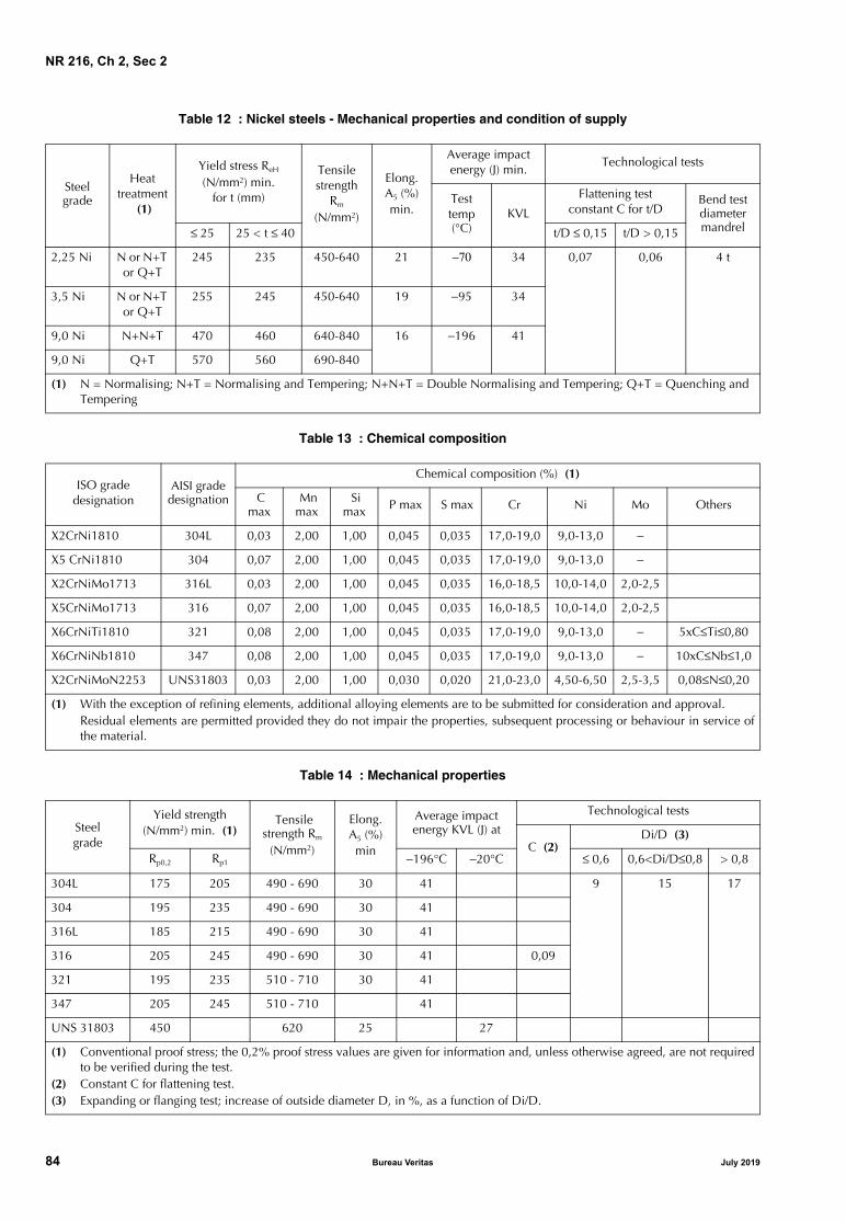
NR 216, Ch 2, Sec 2
Table 12 : Nickel steels - Mechanical properties and condition of supply
Table 13 : Chemical composition
Table 14 : Mechanical properties
Steel grade
Heattreatment
(1)
Yield stress ReH
(N/mm2) min.for t (mm)
Tensilestrength
Rm
(N/mm2)
Elong.A5 (%)min.
Average impactenergy (J) min.
Technological tests
Testtemp (°C)
KVL
Flattening testconstant C for t/D
Bend test diameter mandrel≤ 25 25 < t ≤ 40 t/D ≤ 0,15 t/D > 0,15
2,25 Ni N or N+T or Q+T
245 235 450-640 21 −70 34 0,07 0,06 4 t
3,5 Ni N or N+T or Q+T
255 245 450-640 19 −95 34
9,0 Ni N+N+T 470 460 640-840 16 −196 41
9,0 Ni Q+T 570 560 690-840
(1) N = Normalising; N+T = Normalising and Tempering; N+N+T = Double Normalising and Tempering; Q+T = Quenching and Tempering
ISO gradedesignation
AISI grade designation
Chemical composition (%) (1)
C max
Mn max
Si max P max S max Cr Ni Mo Others
X2CrNi1810 304L 0,03 2,00 1,00 0,045 0,035 17,0-19,0 9,0-13,0 −
X5 CrNi1810 304 0,07 2,00 1,00 0,045 0,035 17,0-19,0 9,0-13,0 −
X2CrNiMo1713 316L 0,03 2,00 1,00 0,045 0,035 16,0-18,5 10,0-14,0 2,0-2,5
X5CrNiMo1713 316 0,07 2,00 1,00 0,045 0,035 16,0-18,5 10,0-14,0 2,0-2,5
X6CrNiTi1810 321 0,08 2,00 1,00 0,045 0,035 17,0-19,0 9,0-13,0 − 5xC≤Ti≤0,80
X6CrNiNb1810 347 0,08 2,00 1,00 0,045 0,035 17,0-19,0 9,0-13,0 − 10xC≤Nb≤1,0
X2CrNiMoN2253 UNS31803 0,03 2,00 1,00 0,030 0,020 21,0-23,0 4,50-6,50 2,5-3,5 0,08≤N≤0,20
(1) With the exception of refining elements, additional alloying elements are to be submitted for consideration and approval.Residual elements are permitted provided they do not impair the properties, subsequent processing or behaviour in service ofthe material.
Steelgrade
Yield strength(N/mm2) min. (1)
Tensile strength Rm
(N/mm2)
Elong.A5 (%)min
Average impact energy KVL (J) at
Technological tests
C (2)Di/D (3)
Rp0,2 Rp1 −196°C −20°C ≤ 0,6 0,6<Di/D≤0,8 > 0,8
304L 175 205 490 - 690 30 41 9 15 17
304 195 235 490 - 690 30 41
316L 185 215 490 - 690 30 41
316 205 245 490 - 690 30 41 0,09
321 195 235 510 - 710 30 41
347 205 245 510 - 710 41
UNS 31803 450 620 25 27
(1) Conventional proof stress; the 0,2% proof stress values are given for information and, unless otherwise agreed, are not requiredto be verified during the test.
(2) Constant C for flattening test.(3) Expanding or flanging test; increase of outside diameter D, in %, as a function of Di/D.
84 Bureau Veritas July 2019

NR 216, Ch 2, Sec 2
7.6 Mechanical and technological tests
7.6.1 Unless they are required to be tested on each length,pipes are to be presented in batches, as specified in Tab 1.
Two pipes are to be selected from each batch for therequired tests, as follows:
a) seamless pipes:
• one tensile test, longitudinal direction
• one flattening test or one bend test with mandreldiameter of 3 t
• 3 Charpy V-notch impact tests, longitudinal direc-tion
• one expansion or flanging test, when required
b) welded pipes:
• one tensile test on base metal, longitudinal direction
• one tensile test transverse to the weld for pipes withD ≥ 300 mm
• two flattening or two bend tests transverse to theweld with mandrel diameter of 3 t
• 3 Charpy V-notch impact tests, longitudinal direc-tion, when required
• one expansion or flanging test when required.
When required, one tensile test at elevated temperature is tobe performed on one sample per cast.
Unless otherwise specified for individual cases, the impacttest of austenitic stainless steel is required only for designtemperature less than −105°C and are to be carried out at -196°C.
7.7 Corrosion tests
7.7.1 For materials used for piping systems for chemicals,the corrosion tests, ASTM A262 Practice E or ASTM A262Practice C (Nitric acid test), as appropriate, may be requiredto be carried out on two pipes per batch.
Tests in accordance with other recognised standards areaccepted, subject to the agreement of the Society.
8 Fittings
8.1 Application
8.1.1 The requirements of this Article apply to seamlessand welded carbon, carbon manganese, low alloy and alloysteel fittings, fabricated from pipes or plates and intendedfor piping systems or pressure plants.
8.2 Steel grades and relevant properties
8.2.1 Fittings fabricated from pipes are to meet the require-ments of Articles [1] to [7], depending on the applications,with respect to manufacture, chemical composition andmechanical properties. Fittings may be hot or cold formedfrom sections of pipes.
Fittings fabricated from plates are to meet the requirementsof the Articles from Sec 1, [1] to Sec 1, [9], depending onthe applications, with respect to manufacture, chemicalcomposition and mechanical properties.
Fittings may be made from sections of plates formed in oneor more shells and welded together. The relevant weldingprocess is to be approved.
8.2.2 Unless otherwise required, the material used for thefabrication of the fittings is to be covered by a works’ certif-icate (W).
8.3 Condition of supply
8.3.1 All fittings are to be in the heat treated or hot workingcondition specified in the various Articles for the corre-sponding material.
Fittings in ferritic steel manufactured by hot forming may bedelivered in the normalised forming condition in lieu ofnormalising, provided that evidence is given of the equiva-lence of such condition; see [1.7.1].
Fittings manufactured by cold forming are in general to besubmitted to heat treatment after forming.
A proposal to deliver fittings in the cold formed conditionmay be considered by the Society; to this end, the Manufac-turer is to submit detailed information relevant to formingprocedure, mechanical properties after forming and desti-nation of the products.
The heat treatment procedure of welded fittings is to bedefined during the approval tests.
8.4 Mechanical properties
8.4.1 The mechanical properties of the finished fittings areto comply with the values specified for the starting materials(plate or pipe).
8.5 Mechanical and technological tests
8.5.1 The fittings are to be presented for testing in batcheshomogeneous for cast and in the number indicated in Tab 1.
A Brinell hardness test HB is to be performed on 10% of thefittings, with a minimum of 3 units, to verify the homogene-ity of the batch. The difference in the hardness value maynot be greater than 30 units.
Two fittings per batch are to be selected for the mechanicaland technological tests specified in Articles [2] to [7]depending on the application.
The tensile tests are to be performed on the hardest and soft-est fittings.
8.6 Non-destructive examination
8.6.1 Unless otherwise specified during the approval proce-dure or in the order, checks with radiographic examinationare in general to be performed on welded fittings with outsidediameter higher than 75 mm, at the Surveyor’s discretion.
8.7 Marking and certification
8.7.1 The requirements specified in Article [1] relevant tomarking in [1.10] and certification in [1.11] are to be com-plied with, as appropriate.
July 2019 Bureau Veritas 85

NR 216, Ch 2, Sec 3
SECTION 3 STEEL FORGINGS
1 General
1.1 Scope
1.1.1 The requirements of this Section apply to steel forg-ings intended for hull, structural applications, offshore con-struction, machinery, boilers, pressure vessels and pipingsystems.These requirements may also be applied to the testing ofsemi-finished products, to be further processed by forging,and to rolled products, when these are acceptable in lieu offorged material. See Sec 1, [8].
This Article specifies the requirements common to all theabove-mentioned steel products, while the appropriate spe-cific requirements are indicated in Articles [2] to [9].
1.1.2 Mass productions For mass produced small forgings, the Manufacturer mayadopt modified procedures for testing and inspection sub-ject to the approval of the Society.
1.1.3 Other specificationsForgings complying with international, national or propri-etary specifications may be accepted by the Society, pro-vided such specifications give reasonable equivalence tothe requirements of these Rules and other relevant Society’sRules or are approved for a specific application.
Such products, when accepted, are designated by their stan-dard identification or as agreed at the time of the approval.
Unless otherwise agreed, survey and certification of steelforgings complying with other specifications are to be car-ried out in accordance with the requirements of these Rulesand other relevant Society’s Rules.
1.1.4 Special requirementsSpecial requirements may be specified in the case of appli-cations intended for dangerous substances or for particu-larly severe service conditions.
In the case of applications involving the storage and trans-port of liquefied gases or fluids at low temperature, refer-ence is to be made to the Society’s Rules for theClassification of Steel Ships Pt D, Ch 9, and, to the Interna-tional Code for the Construction and Equipment of ShipsCarrying Liquefied Gases in Bulk (IGC Code).
For gas fuelled ships, reference is to be made to SocietyRule Note NR 529, and, to the International Code of Safetyfor Ships using Gases or other Low-flash point Fuels (IGFCode).
1.2 Manufacture
1.2.1 Manufacturing process
The steel is to be manufactured as detailed in Sec 1, [1.2].
Adequate top and bottom discards of the ingots are to bemade to ensure freedom from piping and harmful segrega-tions in the finished forgings.
Hot forging, to be carried out within the temperature rangespecified, is to be gradual and uniform and extended, as faras possible, to the final dimensions of the piece.
The plastic deformation is to be such as to ensure sound-ness, uniformity of structure and satisfactory mechanicalproperties after heat treatment.
At an appropriate stage of manufacture, after completion ofall hot working operations, forgings are to be suitably heattreated to refine the grain structure and to obtain therequired mechanical properties.
1.2.2 Reduction ratio
The reduction ratio is to be calculated with reference to theaverage cross-sectional area of the cast material. Where thecast material is initially upset, this reference area may betaken as the average cross-sectional area after this opera-tion. Unless otherwise approved the total reduction ratio isto be at least as specified in Tab 1.
Table 1 : Reduction Ratio
Raw material Finished productTotal Reduction Ratio
Ingot, forged bloom or billet Forging 3:1 where L>D (1) 1,5:1 where L≤ D (1)
Rolled product Forging 4:1 where L>D (1) 2:1 where L≤ D (1)
In a case of an initial forging reduction: Ingot, billet, rolled product
Forging made by upsetting1,5:1 and L0/L1 ≥ 3 (2)
In a case of no initial forging reduction: forging Forging made by upsetting 1,5:1 and L0/L1 ≥ 2 (2)
(1) L and D are the length and diameter respectively of the part of the forging under consideration(2) L0 is the length before upsetting and L1 is the length after upsetting
86 Bureau Veritas July 2019

NR 216, Ch 2, Sec 3
1.2.3 Flame and arc-air shaping
The shaping of forgings or rolled slabs and billets by flamecutting, scarfing or arc-air gouging is to be undertaken inaccordance with recognised good practice and, unless oth-erwise approved, is to be carried out before the final heattreatment. Preheating is to be employed when necessitatedby the composition and/or thickness of the steel. For certaincomponents, subsequent machining of all flame cut sur-faces may be required.
1.2.4 Welding of forgings
When two or more forgings are joined by welding to form acomposite component, the proposed welding procedurespecification is to be submitted for approval. Welding pro-cedure qualification tests may be required.
1.3 Approval
1.3.1 Manufacturers of steel forgings are to be recognisedby the Society in accordance with the Society’s Rule NoteNR320.
1.3.2 When required in the relevant articles, provisions forapproval of manufacturing process are given in the Society’sRule Note NR480.
1.4 Quality of materials
1.4.1 All forgings are to be free from surface or internaldefects which would be detrimental to their proper applica-tion in service.
1.5 Chemical composition
1.5.1 All forgings are to be made from killed steel and thechemical composition is to be appropriate for the type ofsteel, dimensions and required mechanical properties of theforgings being manufactured.
The chemical composition of each heat is to be determinedby the Manufacturer on a sample taken preferably duringthe pouring of the heat. When multiple heats are tappedinto a common ladle, the ladle analysis shall apply.
The chemical composition is to comply with the overalllimits given in the relevant Articles of this Section or, whereapplicable, the requirements of the approved specification.
At the option of the Manufacturer, suitable grain refiningelements such as aluminium, niobium or vanadium may beadded. The content of such elements is to be reported.
Elements designated as residual elements in the individualspecifications are not to be intentionally added to the steel.The content of such elements is to be reported.
1.5.2 Carbon equivalent (CEQ) values, when used in thisSection, are calculated using the following formula:
1.6 Heat treatment (including surface hardening and straightening)
1.6.1 The forgings are to be supplied in the heat treatedcondition.Heat treatment is to be carried out in suitable furnaces asdetailed in Ch 1, Sec 1, [2.3.1].
If, for any reason, a forging is subsequently heated for fur-ther hot working, the forging is to be reheat treated.
1.6.2 The acceptable heat treatment conditions are indi-cated in the Articles relevant to the various forged products.When more than one heat treatment condition is specified,the choice of the supply condition, unless otherwiserequired, is left to the Manufacturer; the condition of supplyis always to be mentioned in the testing documentation.
1.6.3 When the heat treatment is quenching and temperingand the piece cannot be forged near the final dimensionsand shape, it is to be worked by rough machining or flamecutting prior to being quenched and tempered.
1.6.4 If a forging is locally reheated or any straighteningoperation is performed after the final heat treatment consid-eration is to be given to a subsequent stress relieving heattreatment.
1.6.5 Where it is intended to surface harden forgings, fulldetails of the proposed procedure and specification are tobe submitted for the approval of the Society. For the pur-poses of this approval, the Manufacturer may be required todemonstrate by test that the proposed procedure gives auniform surface layer of the required hardness and depthand that it does not impair the soundness and properties ofthe steel.
1.6.6 Where induction hardening or nitriding is to be car-ried out, forgings are to be heat treated at an appropriatestage to a condition suitable for this subsequent surfacehardening.
1.6.7 Where carburising is to be carried out, forgings are tobe heat treated at an appropriate stage (generally either byfull annealing or by normalizing and tempering) to a condi-tion suitable for subsequent machining and carburising.
1.6.8 The forge is to maintain records of heat treatmentidentifying the furnace used, furnace charge, date, tempera-ture and time at temperature. The records are to be pre-sented to the surveyor and copies provided on request.
1.7 Mechanical tests
1.7.1 General The requirements relevant to the type and number of tests tobe carried out are given in the Articles relevant to the vari-ous products.
Test material, sufficient for the required tests and for possi-ble retest purposes, is to be provided with a cross-sectionalarea of not less than that part of the forging which it rep-resents.
Except for components which are to be carburised or forhollow forgings where the ends are to be subsequently
CEQ C Mn6--------- Cr Mo V+ +
5-------------------------------- Ni Cu+
15--------------------- %+ + +=
July 2019 Bureau Veritas 87

NR 216, Ch 2, Sec 3
closed, test material is not to be cut from a forging until allheat treatment has been completed.
For forgings to be carburised after machining, sufficient testmaterial is to be provided both for preliminary tests afterforging and for final tests after completion of carburising[5.7.1].
For forgings to be hot worked and/or heat treated by thepurchaser, the samples to be tested at the Manufacturer’sworks are to be forged and heat treated accordingly.
1.7.2 Individual testingFor forgings in quenched and tempered condition having amass of more than 500 kg, and, forgings in others deliveryconditions having a mass of more than 1000 kg, individualtesting is to be applied. The test material is to be integralwith each forging and is to be taken from a suitable exten-sion as specified in the various Articles and in accordancewith Fig 4 to Fig 10.
Where one forging is subsequently divided into a number ofcomponents, all of which are heat treated together in thesame furnace charge, for test purposes this may be regardedas one forging and the number of tests required is to berelated to the total length and mass of the original multipleforging.
1.7.3 Batch testing A batch testing procedure may be adopted in the followingcases:
a) Forgings in normalized or solution treated conditionwith mass up to 1000 kg each of similar shape anddimensions, made from the same heat, heat treated inthe same furnace charge and with a total mass of thebatch not exceeding 6 tonnes
b) Forgings in quenched and tempered condition withmass up to 500 kg each of similar shape and dimen-sions, made from the same heat, heat treated in thesame furnace charge and with a total mass of the batchnot exceeding 3 tonnes
The test material may be cut from one or more forgings ofthe batch [1.7.5] or, alternatively, separately forged testmaterial may be used. When separately forged, the testmaterial is to have a reduction ratio similar to that used forthe forgings represented. They are to be properly identifiedand heat treated together with the forgings of the batch.
When samples are integral with the forging, the require-ments of [1.7.2] apply.
1.7.4 Batch testing for rolled productsWhen the use of rolled bars as a substitute for forging mate-rial is permitted, a batch testing procedure may be adoptedand the batch composition is to be as follows:
a) Bars made from the same rolled ingot or bloom pro-vided that where this is cut into individual lengths, theseare all heat treated in the same furnace charge, or:
b) Bars of the same diameter made from the same heat,heat treated in the same furnace charge and with a totalmass of the batch not exceeding 2,5 t.
The test samples are taken from one or more pieces of thebatch [1.7.5].
1.7.5 Sampling
In the case of individual testing [1.7.2], the number andposition of samples necessary for the required tests aregiven in the Articles relevant to the various products.
In the case of batch testing [1.7.3], one sample at least is tobe taken from the forging representative of the batch; wherethe number of pieces in the batch exceeds 20, two samplesare to be taken.
A set of test specimens is to consist of:
a) one tensile test specimen
b) three Charpy V-notch impact tests specimens whenrequired in the Articles relevant to the various products.
1.7.6 Preparation of test specimens
Test specimens are normally to be cut from the sampleswith their axes either mainly parallel (longitudinal tests) ormainly tangential (tangential test) to the principal axialdirection of each product, as required in the Articles rele-vant to the various products.
Unless otherwise agreed, the longitudinal axis of the testspecimens is to be positioned as follows:
a) for thickness or diameter up to maximum 50 mm, theaxis is to be at the mid-thickness or the center of thecross-section.
b) for thickness or diameter greater than 50 mm, the axisis to be at one quarter thickness (mid-radius) or 80 mm,whichever is less, below any heat treated surface.
For the preparation of test specimens, reference is made tothe applicable requirements of Ch 1, Sec 2.
1.7.7 Tensile test
Reference is made to the applicable requirements of Ch 1,Sec 2.
The results of the tensile test at ambient temperature are tocomply with the requirements in the appropriate Tables, orin the approved specification when steels other than thosespecified in these Rules are accepted.
Reference is made to [7.7] for the properties at elevatedtemperatures and their verification, when required.
1.7.8 Impact test
Reference is made to the applicable requirements of Ch 1,Sec 2.
The average value of a set of 3 tests is to comply with theaverage value required in the appropriate Tables, or in theapproved specification when steels other than those speci-fied in these Rules are accepted.
Only one individual value may be lower than the averagevalue required, provided that it is not less than 70% of it.
The minimum average values for impact tests indicated inthe Tables are relevant to standard specimens 10 x 10 mm2.
88 Bureau Veritas July 2019
NR 216, Ch 2, Sec 3
1.7.9 Hardness tests
At the discretion of the Society, hardness tests may berequired on the following:
a) quenched and tempered gear forgings after completionof heat treatment and prior to machining the gear teeth[5.6.2]
b) surface-hardened gear forgings after the teeth have beenground to the finished profile [5.7.2]
c) surface-hardened forgings in general
d) batch tested forgings: at least one hardness test on eachforging
The results of hardness tests in the cases a) and d) are to bereported.
The results of hardness tests in the cases b) and c) are tocomply with the approved specification.
1.7.10 Re-test procedures
Samples for possible re-tests are to be taken as near as prac-ticable to the specimens used for the original tests but alter-natively may also be taken from another test position orsample representative of the forging or batch of forgings.
Reference is made to Ch 1, Sec 1, [3.5].
For tensile re-test procedure, reference is made to Ch 1, Sec2, [2.3].
For Charpy V-notch re-test procedure, reference is made toCh 1, Sec 2, [4.4].
1.8 Pressure test
1.8.1 Forgings subjected to internal pressure are to be sub-jected to a hydraulic pressure test in compliance with theconditions laid down in the applicable parts of the Rules.
The test pressure is to be measured by means of a suitablecalibrated pressure gauge.
The test is to be performed on the forging in the finishedcondition and before the application of any coating whichmay conceal the effect of the test.
Unless otherwise agreed, the test of forgings is to be carriedout in the presence of the Surveyor.
A report confirming the satisfactory results of the pressuretests and indicating the relevant testing conditions is to beissued by the Manufacturer.
1.9 Visual and dimensional examination
1.9.1 Visual examination
All products are to be submitted by the Manufacturer tovisual examination; where applicable this is to include theexamination of internal surfaces and bores.
Forgings are also to be presented to the Surveyor for visualexamination.
1.9.2 Verification of dimensionsThe verification of dimensions and tolerances is the respon-sibility of the Manufacturer.
Checks of dimensions for verification of compliance withthe approved drawings are in general required for importantforgings, to the Surveyor’s satisfaction.
1.10 Non-destructive examination
1.10.1 GeneralWhen required by the relevant construction Rules, by theSociety on the approved plans, by the approved procedurefor welded composite components or, in particular cases,by the Surveyor, appropriate non-destructive testing is alsoto be carried out in accordance with a recognized standard.
The extent of testing and acceptance criteria are to beagreed with the Society. The IACS Recommendation No.68is regarded as an example of an acceptable standard.
Non-destructive examinations are to be carried out by per-sonnel qualified and certified in accordance with recog-nized standards or schemes such as ISO 9712, EN 473 orASNT.
The Manufacturer is to provide the Surveyor with a reportconfirming that the required examinations have been car-ried out without revealing significant defects, including ref-erence of the testing standard and the agreed acceptancecriteria.
1.10.2 Magnetic and liquid penetrant examinationMagnetic particle or liquid penetrant testing is to be carriedout when the forgings are in the finished condition.
Where current flow methods are used for magnetisation,particular care is to be taken to avoid damaging machinedsurfaces by contact burns from the prods.
Unless otherwise agreed, these tests are to be carried out inthe presence of the Surveyor.
1.10.3 Ultrasonic examinationUltrasonic examination is to be carried out following thefinal heat treatment and at a stage when the forgings havebeen machined to a condition suitable for this type ofexamination.
Both radial and axial scanning are to be carried out, whenappropriate for the shape and dimensions of the forgingbeing examined.
This examination is to be carried out by the Manufacturer,although Surveyors may request to be present.
1.11 Rectification of defects
1.11.1 Rectification of defects by grindingDefects may be removed by grinding or chipping and grind-ing provided the component dimensions are acceptable.
The resulting grooves are to have a bottom radius of approx-imately three times the groove depth and are to be blendedinto the surrounding surface so as to avoid any sharp con-tours. Complete elimination of the defective material is tobe verified by magnetic particle testing or liquid penetranttesting.
July 2019 Bureau Veritas 89

NR 216, Ch 2, Sec 3
1.11.2 Rectification of defects by weldingRepair welding of forgings except crankshaft forgings maybe permitted subject to prior approval of the Society.
In such cases, full details of the extent and location of therepair, the proposed welding procedure, heat treatment, ifany, and subsequent inspection procedures, are to be sub-mitted for the approval.
Records of repairs and subsequent inspections traceable toeach forging repaired are to be prepared by the forgingManufacturer. The records are to be presented to the Sur-veyor on request.
1.12 Identification and marking
1.12.1 The Manufacturer is to adopt a system of identifica-tion which will enable all finished forgings to be traced tothe original cast and their manufacturing.
All forgings which have been tested with satisfactory resultsare to be marked with the following details:
a) Manufacturer’s name or trade mark
b) Society’s brand
c) Identification mark for the grade of steel
d) Cast number or other marking which will enable thehistory of the fabrication of the forging to be traced
e) Additional, optional marks such as file number andcode of local inspection office, Surveyor’s personalbrand
f) Test pressure, where applicable.
Modified arrangements for identification and marking ofsmall forgings manufactured in large numbers may beagreed with the Society.
1.13 Documentation and certification
1.13.1 The testing documentation indicated in Ch 1, Sec 1,[4.2.1] is to be issued and is to include all the information,as appropriate.
Where applicable, the reports relevant to the non-destruc-tive examination [1.10.1], weld repair [1.11.2] and pressuretest [1.8.1] are to be enclosed with the testing documenta-tion.
1.13.2 When the steel is cast in a mill other than thatwhere the forgings are manufactured, the Surveyor is to besupplied with a steelmaker’s certificate stating the manufac-turing process, the grade of steel, the cast number and therelevant ladle analysis.
2 Forgings for hull, offshore structures and welded components in general
2.1 Scope
2.1.1 The requirements of this Article apply to steel forg-ings intended for ship hull structures, such as sternframes,rudder horns, offshore structures and welded componentsin general, where design and acceptance tests are related tomechanical properties at ambient temperature.
2.2 Steel grades
2.2.1 The grades are identified by the symbol FC (forgingsin carbon and carbon-manganese steels) or FA (forgings inalloy steels), followed by a number giving the minimumspecified ultimate tensile strength Rm, in N/mm2.
2.2.2 Where it is proposed to use alloy steels, the specifica-tion of the steel grade (chemical composition, heat treat-ment and mechanical properties) is to be submitted forapproval.
2.3 Manufacture
2.3.1 Approval
Forgings having a mass above 1000kg or with a diameterabove 200mm are to be manufactured at works which areapproved by the Society. Provisions are given in [1.3].
2.4 Condition of supply
2.4.1 The forgings are to be supplied in one of the follow-ing conditions, as appropriate:
• Carbon and carbon-manganese steels:
- fully annealed
- normalized
- normalized and tempered
- quenched and tempered
• Alloy steels:
- quenched and tempered.
Alternatively, alloy steel forgings may be supplied in thenormalized and tempered condition, in which case thespecified mechanical properties are to be agreed with theSociety.
For all types of steel the tempering temperature is to be notless than 550°C.
2.5 Chemical composition
2.5.1 Reference is made to [1.5]. The chemical composi-tion on ladle analysis is to comply with the limits given inTab 2 or, where applicable, the requirements of theapproved specification.
2.5.2 Maximum carbon equivalent (CEQ) value specified forforgings for offshore structures and components is to beagreed with the Society.
2.6 Mechanical properties
2.6.1 Tab 3 gives the minimum requirements for yieldstress, elongation, reduction of area and impact test energyvalues corresponding to different strength levels. Where it isproposed to use a steel with a specified minimum tensilestrength intermediate to those given, corresponding mini-mum values for the other tensile properties may be obtainedby interpolation.
90 Bureau Veritas July 2019

NR 216, Ch 2, Sec 3
Table 2 : Chemical composition limits
Table 3 : Mechanical properties for hull steel forgings
2.6.2 Forgings intended for the poop structure of ships withice class notation are to be Charpy V-notch impact tested at0°C with 27 J minimum average energy in longitudinaldirection.
2.6.3 For forgings operating at 0°C or lower temperature,which are not dealt with in this Article, the applicablerequirements are to be agreed with the Society dependingon the design temperature, application and dimensions; seealso Article [8].
2.6.4 Charpy V-notch impact tests requirements applicableto forgings for offshore structures and components are to beagreed with the Society in accordance with the Society’sOffshore Rules.
2.7 Mechanical tests
2.7.1 In the case of individual testing as in [1.7.2], at leastone test sample is to be taken for the required tests.
Where a forging exceeds both 4 tons in mass and 3 m inlength, one test sample is to be taken from each end. Theselimits refer to the as forged mass and length but excludingthe test material.
2.7.2 In the case of batch testing, the number of test sam-ples is given in [1.7.3].
2.7.3 The test specimens for 1 tensile and 3 Charpy V-notchimpact tests are to be taken from each test sample.
Unless otherwise agreed the tests specimens are to be cut ina longitudinal direction as per [1.7.6].
2.8 Non-destructive examination
2.8.1 Magnetic particle and ultrasonic examination are tobe carried out on forgings and as mentioned in [1.10].
Steel type C Si Mn P S Cr Mo Ni Cu (2)Total
residuals
C, C-Mn 0,23 (1) 0,45 0,30-1,50 0,035 0,035 0,30 (2) 0,15 (2) 0,40 (2) 0,30 0,85
Alloy (3) 0,45 (3) 0,035 0,035 (3) (3) (3) 0,30 −
Note 1: Composition given in percentage mass by mass maximum unless shown as a range.(1) The carbon content may be increased above this level provided that the carbon equivalent (CEQ), in %, is not more than 0,41%
calculated using the following formula, except for forgings intended for offshore structures where maximum CEQ values are tobe agreed with the Society:
(2) Elements are considered as residual elements.(3) Specification is to be submitted for approval.
Steel typeTensile strength Rm min. (N/mm2)
(1)
Yield stress ReH min. (N/mm2)
Elongation A5 min. (%) Reduction of area Z min. (%)
Charpy V-notchaverage energy min.at + 20°C (2) (3)
Long. Tang. Long. Tang. Long. Tang.
C and C-Mn 400 200 26 19 50 35 32 18
440 220 24 18 50 35 32 18
480 240 22 16 45 30 32 18
520 260 21 15 45 30 32 18
560 280 20 14 40 27 32 18
600 300 18 13 40 27 32 18
Alloy 550 350 20 14 50 35 41 24
600 400 18 13 50 35 41 24
650 450 17 12 50 35 41 24
(1) The following ranges for tensile strength may be additionally specified:• specified minimum tensile strength: < 600 N/mm2 ≥ 600 N/mm2
• tensile strength range: 120 N/mm2 150 N/mm2.(2) For steel forgings intended for the poop structure of ships with ice class notation, Charpy V-notch minimum average energy
long. is to be 27 J at 0°C for all grades.(3) Not applicable to steel forgings for offshore structures and components. See [2.6.4].
Ceq C Mn6--------- Cr Mo V+ +
5-------------------------------- Ni Cu+
15---------------------+ + +=
July 2019 Bureau Veritas 91

NR 216, Ch 2, Sec 3
3 Forgings for machinery, shafts and non-welded components in general
3.1 Scope
3.1.1 The requirements of this Article apply to carbon, car-bon-manganese and alloy steel forgings, intended for use inthe construction of machinery, shafts and non-welded com-ponents including offshore equipment like rings for slewingbearings of cranes and offshore loading systems. Specific requirements for anchors are given in Ch 4, Sec 1,[1].
3.1.2 When welding is expected on rudder stocks, tillersand pintles, the requirements of [2] apply, unless otherwiseagreed by the Society.
3.2 Steel grades
3.2.1 The grades are identified by one of the symbols FC(forgings in carbon and carbon-manganese steels) or FA(forgings in alloy steels), followed by a number giving thespecified minimum tensile strength Rm in N/mm2.
3.3 Manufacture
3.3.1 ApprovalForgings having a mass above 1000kg or with a diameterabove 200mm are to be manufactured at works which areapproved by the Society. Provisions are given in [1.3].
3.4 Condition of supply
3.4.1 The forgings are to be supplied in one of the follow-ing conditions, as appropriate:• Carbon and carbon-manganese steels:
- fully annealed- normalized- normalized and tempered- quenched and tempered
• Alloy steels:- quenched and tempered.
Alternatively, alloy steel forgings may be supplied in thenormalized and tempered condition, in which case thespecified mechanical properties are to be agreed with theSociety.
For all types of steel the tempering temperature is to be notless than 550°C.
3.5 Chemical composition
3.5.1 General
Reference is made to [1.5]. The chemical composition on ladleanalysis is to comply with the limits given in Tab 4 or, whereapplicable, the requirements of the approved specification.
3.6 Mechanical properties
3.6.1 Tab 5 gives the minimum requirements for yieldstress, elongation, reduction of area corresponding to differ-ent strength levels. Where it is proposed to use a steel witha specified minimum tensile strength intermediate to thosegiven, corresponding minimum values for the other tensileproperties may be obtained by interpolation.
3.6.2 Forgings intended for propeller shafts, rudder stocks,pintles, blade bolts, CP mechanisms, shaft bolts, strut-podconnecting bolts of ships with ice class notation ICE CLASSIA SUPER, ICE CLASS IA,ICE CLASS IB or ICE CLASS IC areto be Charpy V-notch impact tested at −10°C with 20 J min-imum average energy in longitudinal direction.
3.6.3 For forgings operating at 0°C or lower temperature,which are not dealt with in this Article, the applicablerequirements are to be agreed with the Society dependingon the design temperature, application and dimensions; seealso Article [8].
3.6.4 Unless otherwise agreed with the Society, carbon andcarbon-manganese steel forgings intended for offshoreequipment are to be Charpy V-notch impact tested with 27 Jminimum average energy in longitudinal direction at a tem-perature to be agreed with the Society in accordance withTab 6.
Alloy steel forgings intended for offshore equipment are tobe Charpy V-notch tested in accordance with the approvedspecifications.
3.7 Mechanical tests
3.7.1 In the case of individual testing as in [1.7.2], at leastone test sample is to be taken for the required tests.
Where a forging exceeds both 4 tons in mass and 3 m inlength, one test sample is to be taken from each end. Theselimits refer to the as forged mass and length but excludingthe test material.
3.7.2 In the case of batch testing, the number of test sam-ples is given in [1.7.3].
Table 4 : Chemical composition limits for non-welded components
Steel type C Si Mn P S Cr Mo Ni Cu (1)Total
residuals
C, C-Mn 0,65 0,45 0,30-1,50 0,035 0,035 0,30 (1) 0,15 (1) 0,40 (1) 0,30 0,85
Alloy 0,45 0,45 0,30-1,00 0,035 0,035 min. 0,40 (2) min. 0,15 (2) min. 0,40 (2) 0,30 −
Note 1: Composition given in percentage mass by mass maximum unless shown as a range or as a minimum.(1) Elements are considered as residual elements unless shown as a minimum.(2) One or more of the elements is to comply with the minimum content.
92 Bureau Veritas July 2019
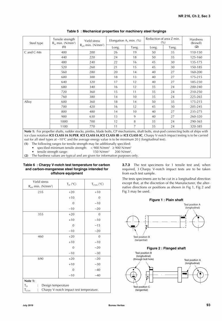
NR 216, Ch 2, Sec 3
Table 5 : Mechanical properties for machinery steel forgings
Table 6 : Charpy V-notch test temperature for carbon and carbon-manganese steel forgings intended for
offshore equipment
3.7.3 The test specimens for 1 tensile test and, whenrequired, 3 Charpy V-notch impact tests are to be takenfrom each test sample.
The tests specimens are to be cut in a longitudinal directionexcept that, at the discretion of the Manufacturer, the alter-native directions or positions as shown in Fig 1, Fig 2 andFig 3 may be used.
Figure 1 : Plain shaft
Figure 2 : Flanged shaft
Steel typeTensile strength Rm min. (N/mm2)
(1)
Yield stress ReH min. (N/mm2)
Elongation A5 min. (%) Reduction of area Z min. (%)
Hardness(Brinell)
(2)Long. Tang. Long. Tang.
C and C-Mn 400 200 26 19 50 35 110-150
440 220 24 18 50 35 125-160
480 240 22 16 45 30 135-175
520 260 21 15 45 30 150-185
560 280 20 14 40 27 160-200
600 300 18 13 40 27 175-215
640 320 17 12 40 27 185-230
680 340 16 12 35 24 200-240
720 360 15 11 35 24 210-250
760 380 14 10 35 24 225-265
Alloy 600 360 18 14 50 35 175-215
700 420 16 12 45 30 205-245
800 480 14 10 40 27 235-275
900 630 13 9 40 27 260-320
1000 700 12 8 35 24 290-365
1100 770 11 7 35 24 320-385
Note 1: For propeller shafts, rudder stocks, pintles, blade bolts, CP mechanisms, shaft bolts, strut-pod connecting bolts of ships with ice class notation ICE CLASS IA SUPER, ICE CLASS IA,ICE CLASS IB or ICE CLASS IC, Charpy V-notch impact testing is to be carried out for all steel types at −10°C and the average energy value is to be minimum 20 J (longitudinal test).(1) The following ranges for tensile strength may be additionally specified:
• specified minimum tensile strength: < 900 N/mm2 ≥ 900 N/mm2
• tensile strength range: 150 N/mm2 200 N/mm2.(2) The hardness values are typical and are given for information purposes only.
Yield stress ReH min. (N/mm2)
TD (°C) TCVN (°C)
235 +20 +10
+10 0
0 −10
−10 −20
355 +20 0
+10 −10
0 −15
−10 −20
460 +20 0
+10 −10
0 −20
−10 −30
690 +20 −20
+10 −30
0 −40
−10 −40
Note 1:TD : Design temperatureTCVN : Charpy V-notch impact test temperature.
Test position B (tangential)
Test position A (longitudinal)
Test position B(longitudinal)
(through bolt hole) Test position A(longitudinal)
Test position C(tangential)
July 2019 Bureau Veritas 93

NR 216, Ch 2, Sec 3
Figure 3 : Flanged shaft with collar
3.8 Non-destructive examination
3.8.1 A magnetic particle or liquid penetrant examinationis to be carried out on forgings intended for:
a) rudder stocks and pintles with diameter not lower than100 mm
b) main propulsion shafting with diameter not lower than100 mm
c) connecting rods
d) components for engines having bore diameter largerthan 400 mm, such as:
• cylinder covers, piston crowns, piston rods, tie rods,gear wheels for camshaft drives
• bolts and studs for cylinder covers, cross heads,main bearing and connecting rod bearings, nuts fortie rods.
The magnetic particle test of tie rods/stay bolts is to includetest at each threaded portion which is at least twice thelength of the thread.
3.8.2 Ultrasonic testing is to be carried out on the follow-ing items:
a) rudder stocks and pintles with diameter not lower than200 mm
b) shafts having a finished diameter of 200 mm or larger, whenintended for main propulsion or other essential services
c) piston crowns and cylinders covers
d) connecting rods, piston rods and crosshead with mini-mum diameter not less than 200 mm or equivalentcross-section.
4 Forgings for crankshafts
4.1 Scope
4.1.1 The requirements of this Article apply to carbon-man-ganese and alloy steel for solid forged crankshafts and forg-ings to be used for the construction of semi-built or fullybuilt crankshafts.
The general requirements, specified in Article [1], are alsoto be complied with, as appropriate.
4.2 Steel grades
4.2.1 The steel specification relevant to chemical composi-tion, mechanical properties and heat treatment is to be sub-mitted for approval.
4.2.2 The specified minimum tensile strength Rm is gener-ally to be not lower than 400 N/mm2 and not higher than1000 N/mm2.
4.3 Manufacture
4.3.1 ApprovalForgings having a mass above 1000kg are to be manufac-tured at works which are approved by the Society. Provi-sions are given in [1.3].
4.3.2 Continuous grain flow forging procedures are to bespecially approved and, to this end, tests effected to demon-strate that a satisfactory structure and grain flow areobtained.In the case of a welded crankshaft, the welding procedure isto be approved.
When the webs are obtained by flame cutting from forgedor rolled flat products, the part to be removed by machiningis to be not less than 8 mm from all flame-cut surfaces.
4.4 Condition of supply
4.4.1 Forgings are to be normalised and tempered orquenched and tempered depending on the approved speci-fication.The tempering temperature is to be not lower than 550°C.
4.4.2 Where a superficial hardening of the crankshaft forg-ing by nitriding or by induction quenching is foreseen, theproposed procedure is to be submitted as indicated in[1.6.5].
4.5 Chemical and mechanical properties
4.5.1 The chemical composition on ladle analysis is tocomply with the approved specification [4.2.1].For alloy steels which are to be nitrided, the phosphorus orsulphur content is to be not greater than 0,020%.
4.5.2 The mechanical properties are to comply with therequirements of the approved specification.
4.6 Mechanical tests
4.6.1 For open die solid forged crankshafts one set of testspecimens is to be taken in the longitudinal direction, fromthe driving shaft end of each forging (test position A in Fig 4).
Where the mass (as heat treated but excluding test material)exceeds 3 tons, the specimens in a longitudinal directionare to be taken from each end (test positions A and B in Fig4). Where however the crankthrows are formed by machin-ing or flame cutting, the second set of specimens is to betaken in a tangential direction from material removed fromthe crankthrow at the end opposite to the driving shaft end(test position C in Fig 4).
Test position B (tangential)
Test position C (tangential)
Test position A (longitudinal)
Test position D (tangential)
94 Bureau Veritas July 2019

NR 216, Ch 2, Sec 3
Figure 4 : Solid forged crankshaft
4.6.2 For crank webs, one set of specimens is to be takenfrom each forging in a tangential direction (test position C inFig 4).
4.6.3 For closed die crankshaft forgings and crankshaftforgings where the method of manufacture has been spe-cially approved in accordance with [4.3], the number andposition of test specimens is to be agreed with the Societyhaving regard to the method of manufacture used.
4.6.4 When small crankshaft forgings are batch tested[1.7.3], hardness tests are to be made on the individualpieces and results are to be reported.
4.7 Non-destructive examination
4.7.1 Magnetic particle and/or liquid penetrant tests arerequired for all crankshaft forgings.Where applicable, this is also to include all flame-cut sur-faces not subsequently machined.
Special care is to be devoted to the pins and journals andassociated fillets.
Unless otherwise agreed, all crankshaft forgings having aminimum crankpin diameter not lower than 150 mm are tobe ultrasonically examined.
4.7.2 Non-destructive examination procedures and theacceptance criteria of the indications of such tests, comply-ing with the requirements of the engine Manufacturer, areto be previously approved by the Society.
5 Forgings for gearing
5.1 Scope
5.1.1 The requirements of this Article apply to carbon-man-ganese and alloy steel forgings intended for the constructionof gearing for main propulsion and auxiliary equipment.The general requirements, specified in Article [1], are alsoto be complied with, as appropriate.
5.1.2 In the case of forgings for flexible couplings, quillshafts and gearwheel shafts, the requirements of Article [3]apply.
5.2 Steel grades
5.2.1 Steels are to comply with requirements specified in[3.2] or with a specification approved by the Society.To this end, a detailed specification relevant to chemicalcomposition, mechanical properties and heat treatment isto be submitted for approval.
5.3 Manufacture
5.3.1 ApprovalForgings having a mass above 1000kg are to be manufac-tured at works which are approved by the Society. Provi-sions are given in [1.3].
5.3.2 The reduction ratio during forging is to be in compli-ance with [1.2.2].Forgings are to be provided with sufficient excess materialas may be necessary for machining out possible defectivezones.
5.4 Condition of supply
5.4.1 Unless otherwise agreed, forgings which are not to besurface-hardened are to be normalised and tempered orquenched and tempered.
5.4.2 Where induction hardening or nitriding is to be car-ried out, forgings are to be heat treated at an appropriatestage to a condition suitable for this subsequent surfacehardening.
5.4.3 Where carburising is to be carried out, forgings are tobe heat treated at an appropriate stage (generally either byfull annealing or by normalizing and tempering) to a condi-tion suitable for subsequent machining and carburising.
5.4.4 Treatments for surface hardening are to be approvedin accordance with [1.6.5].
5.5 Chemical and mechanical properties
5.5.1 The chemical composition and the mechanical prop-erties are specified in [3.5] and [3.6], respectively, or in theapproved specification as applicable.
Test position A(longitudinal)
Test position B(longitudinal)
Test position C(tangential)
Coupling end
July 2019 Bureau Veritas 95

NR 216, Ch 2, Sec 3
Figure 5 : Pinions
L : Length of toothed portion, in mmD : Diameter of toothed portion, in mmd : Journal diameter, in mm.
5.6 Mechanical tests for normalised and tempered or quenched and tempered forgings
5.6.1 Sampling The specimens necessary for the required tests are to betaken from each forging [1.7.2] or a forging representativeof the batch [1.7.3], in accordance with Fig 5, Fig 6, Fig 7and Fig 8.
The set of test specimens is to be taken as follows:
• Pinions (see Fig 5):
Where the finished machined diameter of the toothedportion exceeds 200 mm, one set of test specimens is tobe taken from each forging in a tangential directionadjacent to the toothed portion (test position B). Wherethe dimensions preclude the preparation of tests fromthis position, tests in a tangential direction are to betaken from the end of the journal (test position C).
If, however, the journal diameter is 200 mm or less, testsare to be taken in a longitudinal direction (test position A).
Where the finished length of the toothed portionexceeds 1,25 m, one set of test specimens is to be takenfrom each end.
Where the finished diameter of the toothed portion is200 mm or less, one set of test specimens is to be takenin a longitudinal direction (test position A).
• Gear wheel (see Fig 6):
One set of tests is to be taken from each forging in a tan-gential direction (test positions A or B).
Figure 6 : Gear wheel
• Gear wheel rims made by expanding (see Fig 7):
One set of tests is to be taken from each forging in a tan-gential direction (test position A or B). Where the fin-ished diameter exceeds 2,5 m or the mass (as heattreated excluding test material) exceeds 3 tons, two setsof test specimens are to be taken from diametricallyopposite positions (test positions A and B). The mechan-ical properties for longitudinal tests are to be applied.
• Pinion sleeves (see Fig 8):
One set of test specimens is to be taken from each forg-ing in a tangential direction (test position A or B). Wherethe finished length exceeds 1,25 m, one set of test spec-imens is to be taken from each end.
Figure 7 : Gear wheel rim made by expanding
Figure 8 : Pinion sleeve
Test position B (tangential)
Test position B (tangential)
Test position A (longitudinal)
Test position C (tangential)
L
D d
Test position A (tangential)
Test position B (tangential)
Test position A(tangential)
Test position B(tangential)
Test position A (tangential)
Test position B (tangential)
96 Bureau Veritas July 2019

NR 216, Ch 2, Sec 3
5.6.2 Hardness tests
Hardness tests may be required at the discretion of the Soci-ety. See also [1.7.9] a).
The hardness is to be determined after completion of heattreatment and prior to machining the gear teeth.
Measurements are to be carried out at four positions equallyspaced around the circumference of the surface where teethwill subsequently be cut. Where the finished diameter ofthe toothed portion exceeds 2,5 m, the above number oftest positions is to be increased to eight.
Where the width of a gear wheel rim forging exceeds1,25 m, the hardness is to be determined at eight positionsat each end of the forging.
5.7 Mechanical tests for surface-hardened forgings
5.7.1 Sampling
Forgings to be carburised after machining are to be pro-vided with sufficient test material for the sets of specimensfor both preliminary tests at the forge and final tests aftercompletion of carburising.
For this purpose two test samples are to be taken from posi-tions as detailed in [5.6] except that irrespective of thedimensions or mass of the forging, tests are required fromone position only and, in the case of forgings with integraljournals, are to be cut in a longitudinal direction.
This test sample is to be machined to a diameter of D/4 or60 mm, whichever is less, where D is the finished diameterof the toothed position.
For preliminary tests at the forge, one test sample is to begiven a blank carburising and heat treatment cycle, simulat-ing that which subsequently will be applied to the forging.
For final acceptance tests, the second test sample is to beblank carburised and heat treated along with the forgingsthey represent.
At the discretion of the Manufacturer, test samples of largercross-section may be either carburised or blank carburised,but these are to be machined to the required diameter priorto the final quenching and tempering heat treatment.
5.7.2 Hardness tests and additional checks
Hardness tests may also be required on forgings which havebeen induction hardened, nitrided or carburised. See also[1.7.9] b).
The hardness is to be determined on the toothed part afterthe teeth have been ground to the finished profile. Theresults of such tests are to comply with the approved speci-fication.
Additional checks of the hardness, depth and shape of thehardened layer are to be performed as indicated in theapproved specification.
When, for nitrided gearing, hardness verification is requiredon additional test samples, unless otherwise stated in theapproved specification, the depth of the hardened zone isto be not lower than 0,6 mm and the hardness at a depth of0,25 mm is to be not lower than 500 Vickers points.
5.8 Non-destructive examination
5.8.1 Magnetic particle or liquid penetrant testing isrequired on the tooth surfaces of gears hardened completelyor at their surface.
An ultrasonic examination of the forgings is to be performedby the Manufacturer when there is still an adequate amountof excess material on the surfaces in respect of the finalposition of the teeth.
In general, ultrasonic examination is required for forginghaving a finished diameter, of the part where teeth will becut, higher than 200 mm.
6 Forgings for turbines
6.1 Scope
6.1.1 The requirements of this Article apply to steel forg-ings intended for the construction of rotors and discs ofmain turbines and rotors of auxiliary turbines driving elec-tric generators and compressors.
The general requirements specified in Article [1] are also tobe complied with, as appropriate.
6.1.2 Plans submitted for approval are to state whether theturbine is for propulsion or for auxiliary service; in the lattercase the shaft power is to be specified.
For rotors to be subjected to a thermal stability test, themaximum design temperature and the proposed test tem-perature are also to be specified.
For rotors of welded construction, the specification of thechemical composition of the steel is to be submitted forapproval.
6.2 Steel grades, chemical composition and mechanical properties
6.2.1 The steel grades and relevant properties may be inaccordance with [3.2], [3.5] and [3.6] or with a particularspecification to be submitted for acceptance.
6.3 Manufacture
6.3.1 Approval
Forgings having a mass above 1000kg are to be manufac-tured at works which are approved by the Society. Provi-sions are given in [1.3].
6.4 Condition of supply
6.4.1 The intermediate and final heat treatments, specifiedby the Manufacturer, are to be submitted for consideration.
In particular, the heat treatments are to be such as to avoidhair-line cracks.
For rotors of welded construction, the heat treatment is tobe specially approved.
July 2019 Bureau Veritas 97

NR 216, Ch 2, Sec 3
Figure 9 : Turbine rotor
6.5 Mechanical tests
6.5.1 For rotors not exceeding 3 tons in mass, one set oflongitudinal specimens is to be taken from one end of theshaft and one set of transverse test specimens is to be takenin the tangential direction from the body portion (see Fig 9).
For rotors exceeding 3 tons in mass, the set of longitudinalspecimens is to be taken from each end of the shaft and theset of transverse test specimens is to be taken in the tangen-tial direction from the body portion (see Fig 9).
For each turbine disc, at least one set of transverse speci-mens is to be taken from the boss in the tangential direction(see Fig 10).
Figure 10 : Turbine disc
6.6 Non-destructive examination
6.6.1 A visual examination, supported by a magnetic parti-cle examination at the discretion of the Surveyor, is requiredfor the end surfaces of the rotors and the boss of the discs;the degree of finishing is to be appropriate for this purpose.
An ultrasonic examination is to be carried out by the Manu-facturer on all forgings.
6.6.2 Rotor forgings for propulsion turbines having a powerexceeding 1100 kW are to be hollow bored to permit inter-nal examination visually and, where possible, by the mag-netic particle method.
These examinations are to be confirmed by the Surveyor;the degree of finishing is to be adequate for the purpose.
At the discretion of the Society, ultrasonic examination ofthe rotor by an approved procedure may be accepted as analternative to hollow boring.
6.7 Thermal stability test
6.7.1 Solid forged rotors and rotors built by welding two ormore forged pieces and intended for turbines having adesign temperature exceeding 400°C are to be subjected,after the final heat treatment and in their rough machinedcondition, to a thermal stability test.The test is to be performed using procedures and equipmentto the satisfaction of the Society.
The deflection may be measured with the procedure out-lined below, which consists in reading the radial elongationin way of some machined zones distributed along thelength of the rotor (in general, there will be two referencemachined zones in way, or in proximity, of the supports andthree test machined zones located one at the mid-lengthand two at the ends of the rotor).
Four markings, 90° apart, are to be stamped for identifica-tion on the coupling end of the rotor.
During the test, the rotor is to be rotated very slowly anduniformly in the furnace, while it is heated gradually andevenly, excessive thermal gradients being avoided; the rotoris to be maintained for a sufficient length of time at thespecified test temperature, which is to be appropriate to thefinal heat treatment of the piece, and subsequently slowlyand uniformly cooled to a sufficiently low temperature,excessive thermal gradients again being avoided.
In the course of the test, the deflections are to be regularlyrecorded in each machined zone, at angular intervals of90°, and the difference in the readings between the coldand hot conditions is not to exceed the specified limits.
In general, the following requirements are to be compliedwith:• the furnace is to be large enough to contain the whole
length of the rotor, including the end zones in way ofthe glands; overhung wheels, when present, are also tobe enclosed in the furnace
• means are to be provided for continuous recording ofthe temperature at the surface of the rotor and, if practi-cable, in a bore at the mid-length of the rotor
• the temperature of the rotor is in no case to exceed thefinal tempering temperature
• the test temperature is to not be less than the maximumdesign temperature +28°C but not higher than the tem-perature mentioned above; the temperature distributionis to be uniform and maintained at a constant level for atleast three hours with the readings falling within0,006 mm in all the machined zones
L direction
L directionL direction
L direction
T directionT direction
T direction
98 Bureau Veritas July 2019

NR 216, Ch 2, Sec 3
• the rotor is to be rotated during cooling until the tem-perature is not more than 100°C
• cold readings are to be taken before and after the test.
The test results are considered satisfactory when the differ-ence between the final readings in the hot conditions andthe initial and final cold readings do not exceed 0,025 mmin any zone.
Otherwise, at the request of the Manufacturer and with theSociety’s approval, the test may be repeated; when theresults of the second test are also unsatisfactory, proposalsfor alterations to the rotor are to be approved by the Societybefore further testing.
7 Forgings for boilers, pressure vessels and systems
7.1 Scope
7.1.1 The requirements of this Article apply to forgingsmade in carbon, carbon-manganese, molybdenum andchromium-molybdenum low alloy steels, intended for theconstruction by welding of boilers and pressure vessels,plants and piping systems in general, when Charpy V-notchproperties at temperature not lower than −20°C are speci-fied.For forgings not intended for welded constructions, therequirements of Article [2] apply, as appropriate.
7.1.2 Forgings intended for vessels and systems operatingat low temperatures are to comply with the applicablerequirements of Article [8] and, in the case of applicationsinvolving the storage and transport of liquefied gases or flu-ids at low temperature, reference is to be made to the Soci-ety’s Rules for the Classification of Steel Ships Part D,Chapter 9, and, to the International Code for the Construc-tion and Equipment of Ships Carrying Liquefied Gases inBulk (IGC Code).For gas fuelled ships, reference is to be made to SocietyRule Note NR 529, and, to the International Code of Safetyfor Ships using Gases or other Low-flash point Fuels (IGFCode).
7.2 Steel grades
7.2.1 Carbon and carbon-manganese steels are classed intothree groups indicating the minimum ultimate tensilestrength Rm, in N/mm2: 410, 460 and 510.
Each group may be further subdivided into grades HA, HBand HD, based on conventional levels of quality and impactproperties.
7.2.2 Low alloy steels are designated according to thechemical composition in the grades 0,3Mo-1Cr0,5Mo-2,25Cr1Mo.The figures mean the nominal percentage content of themain alloying elements.
Where it is proposed to use steels other than those dealtwith in these Rules, the steel specification relevant to chem-ical composition, mechanical properties and heat treatmentis to be submitted for approval.
7.3 Manufacture
7.3.1 ApprovalForgings having a mass above 1000kg are to be manufac-tured at works which are approved by the Society. Provi-sions are given in [1.3].
7.4 Condition of supply
7.4.1 The forgings are to be supplied in one of the follow-ing conditions, as appropriate:
• Carbon and carbon-manganese steels:
- normalized
- normalized and tempered
- quenched and tempered
• Alloy steels:
- quenched and tempered.
Alternatively, alloy steel forgings may be supplied in the nor-malized and tempered condition, in which case the specifiedmechanical properties are to be agreed with the Society.
For all types of steel the tempering temperature is to be notless than 550°C.
7.5 Chemical composition
7.5.1 The chemical composition on ladle analysis is tocomply with the limits specified in Tab 7 for carbon andcarbon-manganese forgings and Tab 8 for Cr and Cr-Moalloy steel forgings.
7.6 Mechanical properties
7.6.1 The mechanical properties are specified in Tab 9 forcarbon and carbon-manganese steel and in Tab 10 for Crand Cr-Mo alloy steel forgings.
7.7 Mechanical properties at elevated temperature
7.7.1 The values for the 0,2% proof stress (Rp0,2) at tempera-tures of 150°C and higher are given in Tab 11.
The above values are for design purposes only. Their verifi-cation is in general not required during the testing, unlessfigures higher than those shown in Tab 11 and in accor-dance with recognised standards are proposed by the steelManufacturer.
In such cases, the verification is required and the proce-dures detailed in [7.7.2] and [7.7.3] are to be followed.
7.7.2 When Rp0,2 is required to be verified, at least one ten-sile test for each cast is to be carried out at the agreed tem-perature on each forging or batch of forgings.
The test specimen is to be taken near the position of the ten-sile specimen tested at ambient temperature.
The dimensions of the specimens and the testing procedureare to be in accordance with the requirements of Ch 1, Sec2, [2.1] and Ch 1, Sec 2, [2.2.5], respectively.
The results of tests are to comply with the specified values.
July 2019 Bureau Veritas 99

NR 216, Ch 2, Sec 3
Table 7 : Carbon and carbon-manganese steels - Chemical composition
Table 8 : Low alloy steels - Chemical composition
Table 9 : Carbon and carbon-manganese steels - Mechanical properties
Table 10 : Low alloy steels - Mechanical properties
Steel grade DeoxidationChemical composition (%) (1)
C max Mn Si P max S max Al tot. min. (1) Ni max
410 HA killed 0,20 0,60 - 1,40 0,10 - 0,40 0,030 0,030 0,40
410 HB killed
410 HD killed and fine grained 0,020
460 HA killed 0,22 0,90 - 1,60 0,10 - 0,50 0,030 0,030 0,40
460 HB killed
460 HD killed and fine grained 0,20 0,020
510 HA killed 0,23 1,00 - 1,60 0,10 - 0,50 0,030 0,030 0,40
510 HB killed
510 HD killed and fine grained 0,20 0,020
(1) Nb, V or Ti may be used for grain refining as a complete or partial substitute for Al, in which case the minimum value for Alcontent does not apply. The grain refining elements are to be specified at the time of approval;in general Nb and V are not to exceed 0,05% and 0,10%, respectively. Additional alloying elements are to be submitted forconsideration and approval. Residual elements not intentionally added are not to exceed the following limits:Cu ≤ 0,30%; Cr ≤ 0,25%; Mo ≤ 0,10%. Total: Ni + Cu + Cr + Mo ≤ 0,80%
Steel grade Deoxidation (2)Chemical composition (%) (1)
C Mn Si P max S max Cr Mo
0,3Mo Si killed 0,12 - 0,22 0,40 - 0,90 0,10 - 0,40 0,030 0,030 − 0,25 - 0,35
1Cr 0,5Mo Si killed ≤ 0,18 0,40 - 1,70 0,10 - 0,40 0,030 0,030 0,80 - 1,15 0,40 - 0,65
2,25Cr 1Mo Si killed ≤ 0,15 0,10 - 0,40 0,10 - 0,40 0,030 0,030 2,00 - 2,50 0,90 - 1,10
(1) Residual elements are not to exceed the following limits: Cu ≤ 0,30%; Ni ≤ 0,30%. (2) Aluminum total is to be lower than 0,020% for all grades of steel. The aluminum content is to be mentioned on the ladle anal-
ysis certificate.
Steel grade
Yield stress ReH (N/mm2)min. for thickness t (mm)
Tensile strength
Rm
(N/mm2)
Elongation A5 (%) min.for thickness t (mm) (1) Average impact energy (J)
min.
t ≤100 100 < t ≤ 250t ≤100 100 < t ≤250
L T L T Test temp (°C) KVL KVT
410 HA 230 220 410 - 530 24 23 23 21 + 20 41 27
410 HB 0 27 22
410 HD 250 230 − 20
460 HA 260 250 460 - 600 23 21 22 20 + 20 41 27
460 HB 0 27 22
460 HD 280 260 − 20
510 HA 280 270 510 - 650 21 20 20 19 + 20 41 27
510 HD 0
510 HD 330 310 − 20
(1) L and T stand for longitudinal and transverse specimens, respectively.
Steel gradeYield stress ReH (N/mm2) min.
for thickness t (mm) (1) Tensile strength Rm (N/mm2)
Elongation A5 (%) min. (2)
Average impact energy (J) min.
t ≤ 100 100 < t ≤ 250 L T Test temp (°C) KVL KVT
0,3Mo 285 270 440 - 570 23 21 +20 50 34
1Cr 0,5Mo 270 255 440 - 590 20 18 44 27
2,25Cr 1Mo 275 275 500 - 650 19 17 60 50
(1) For thickness or diameter greater than 250 mm, values are to be agreed with the Society.(2) L and T stand for longitudinal and transverse specimens, respectively.
100 Bureau Veritas July 2019

NR 216, Ch 2, Sec 3
Table 11 : Minimum proof stress (Rp0,2) values at elevated temperatures
7.7.3 As an alternative to the systematic verification of therequired Rp0,2 as in [7.7.2], it may be agreed with the indi-vidual steelmakers to carry out an adequate program of testsor to adequately check the statistical data of the current pro-duction.
7.7.4 The values of the estimated average stress to rupturein 100.000 hours are given, for design purposes only, in Sec1, Tab 26.
7.8 Mechanical tests
7.8.1 With the exception of drums (see [7.8.2]), at least oneset of specimens for mechanical tests (1 tension and unlessotherwise required 3 Charpy V-notch specimens for typeHB and HD) is to be taken from each forging [1.7.2] orbatch [1.7.3]; unless otherwise agreed and when possible,specimens are to be taken in the longitudinal direction.
7.8.2 For drum forgings, one set of specimens for mechani-cal tests is to be taken from each open end.
When, depending on the manufacturing procedure, the testsamples are to be detached before heat treatment, they areto be heat treated with the forging they represent.
The specimens are to be cut in the circumferential direc-tion. Where the tensile test is carried out on specimenstaken at both ends of a drum forging, the variation in tensilestrength Rm on the two tests is not to exceed 70 N/mm2.
7.8.3 For tensile tests at elevated temperatures, the require-ments of [7.7.2] apply.
7.9 Non-destructive examination
7.9.1 Unless otherwise required or agreed, at least the fol-lowing non-destructive examinations are to be carried out:• forgings are to be examined by the magnetic particle
method• drum forgings and other similar important forgings hav-
ing thickness higher than 10 mm are to be examined byultrasonic method.
8 Ferritic steel forgings for low temperature service
8.1 Scope
8.1.1 The requirements of this Article apply to ferritic steelforgings intended for welded structural use as in the con-struction of structures, vessels, plants and piping systems forlow temperature service or when, irrespective of the serviceconditions, they are required to satisfy specified impactproperties at temperatures lower than −20°C.
8.1.2 In the case of applications involving the storage andtransport of liquefied gases or fluids at low temperature, ref-erence is to be made to the Society’s Rules for the Classifi-cation of Steel Ships Part D, Chapter 9, and, to theInternational Code for the Construction and Equipment ofShips Carrying Liquefied Gases in Bulk (IGC Code).For gas fuelled ships, reference is to be made to SocietyRule Note NR 529, and, to the International Code of Safetyfor Ships using Gases or other Low-flash point Fuels (IGFCode).
8.2 Steel grades and relevant properties
8.2.1 The requirements apply to carbon, carbon-manga-
nese and nickel alloy steels.
Steel grade Thickness(mm)
Rp0,2 (N/mm2) at a temperature (°C) of
150 200 250 300 350 400 450 500
410 HA (1)410 HB (1)
≤ 100> 100
190175
180170
170160
150150
140140
135135
135135
410 HD (1) ≤ 100> 100
205190
190175
170165
150150
140140
135135
130130
460 HA (1)460 HB (1)
≤ 100> 100
215200
210200
195190
175−
170-
160−
155−
460 HD (1) ≤ 100> 100
235220
215200
200190
175175
165−
155−
150−
510 HB (1) ≤ 100> 100
235220
225210
210200
190190
180−
175−
170−
510 HD (1) ≤ 100> 100
255240
235215
215205
190190
180−
170−
165−
0,3Mo 200 185 170 160 150 140 130
1Cr 0,5Mo 210 200 180 170 160 150 140
2,25Cr 1Mo 240 230 220 210 200 190 180
(1) The values at Rp0,2 for temperatures ≤ 250°C are for guidance only.
July 2019 Bureau Veritas 101

NR 216, Ch 2, Sec 3
The steel specification relevant to chemical composition,mechanical properties and heat treatment is to be submittedfor approval.
Reference can be made to the steel designation, chemicalcomposition and mechanical properties relevant to the rolledmaterials to which the forgings are intended to be welded, i.e.in particular, for these Rules, to Sec 1, Tab 27 and Sec 1, Tab29 for carbon and carbon-manganese steels, and to Sec 1, Tab28 and Sec 1, Tab 31 for nickel alloy steels.
8.3 Manufacture
8.3.1 ApprovalForgings having a mass above 1000kg are to be manufac-tured at works which are approved by the Society. Provi-sions are given in [1.3].
8.4 Condition of supply
8.4.1 Forgings are to be normalised, normalised and tem-pered or quenched and tempered, depending on the gradeof steel, as indicated in Sec 1, [7.4.1] or in the approvedspecification.
8.5 Mechanical tests
8.5.1 At least one set of specimens for mechanical tests(1 tensile and 3 Charpy V-notch specimens) is to be takenfrom each forging [1.7.2] or batch [1.7.3]; unless otherwiseagreed and when possible, specimens are to be cut in thelongitudinal direction.
The impact tests are generally to be carried out at the mini-mum temperature stated for the type of steel; a higher testtemperature may be agreed with the Society, however,depending on the design temperature of the individualapplications.
8.6 Non-destructive examination
8.6.1 Unless otherwise required or agreed, forgings are tobe examined by the magnetic particle method.
When the above forgings have thickness higher than 10mm,they are also to be subjected to ultrasonic examination.
9 Stainless steel forgings
9.1 Scope
9.1.1 The requirements of this Article apply to stainlesssteel forgings intended for construction of cargo and storagetanks, pressure vessels, and piping fittings for chemicaland/or low temperature applications.
9.1.2 Austenitic stainless steels are suitable for use at bothelevated and low temperatures where the design tempera-ture is not lower than −165°C.
When austenitic stainless steels are proposed for use at ele-vated temperatures, details of chemical composition,mechanical properties and heat treatment are to be submit-ted for consideration and approval.
9.1.3 Stainless steels may also be used for shafts andmachinery applications under Article [3].
9.1.4 In the case of applications involving the storage andtransport of liquefied gases or fluids at low temperature, ref-erence is to be made to the Society’s Rules for the Classifi-cation of Steel Ships Part D, Chapter 9, and, to theInternational Code for the Construction and Equipment ofShips Carrying Liquefied Gases in Bulk (IGC Code).
For gas fuelled ships, reference is to be made to Society RuleNote NR 529, and, to the International Code of Safety forShips using Gases or other Low-flash point Fuels (IGF Code).
9.2 Steel grades and relevant properties
9.2.1 The requirements apply to austenitic Cr-Ni steels.
The general requirements relevant to designation, chemicalcomposition, mechanical properties and condition of sup-ply are specified in Sec 1, [9] relevant to rolled products.
9.2.2 Forgings made in stainless steels other than austeniticand intended for blade bolts, CP mechanisms, shaft bolts,strut-pod connecting bolts of ships having class notation ICECLASS IA SUPER, ICE CLASS IA, ICE CLASS IB or ICECLASS IC are to be Charpy V-notch impact, tested at −10°Cwith 20 J minimum average energy in longitudinal direction.
9.2.3 Other types of stainless steels (ferritic-austenitic ormartensitic), complying with international or national spec-ifications, may be accepted for particular applications (e.g.[9.1.3]); their relevant specification is to be submitted forapproval.
9.3 Manufacture
9.3.1 Approval
Forgings having a mass above 1000kg are to be manufac-tured at works which are approved by the Society. Provi-sions are given in [1.3].
9.4 Mechanical tests
9.4.1 Sampling and mechanical tests are to be in compli-ance with the requirements of [3.7] and [7.8], as appropri-ate, depending on the application (machinery or pressuresystems).
Unless otherwise required, impact tests on the austeniticgrades are to be performed for a design temperature lowerthan −105°C and are to be carried out at −196°C.
The results of the tests are to be in accordance with therequirements of Sec 1, [9.6.1].
9.5 Non-destructive examination
9.5.1 Unless otherwise required or agreed, forgings are tobe examined by the liquid penetrant test and/or by the ultra-sonic method, as appropriate, depending on the applica-tion.
102 Bureau Veritas July 2019

NR 216, Ch 2, Sec 3
9.6 Corrosion tests
9.6.1 For forgings intended for chemicals, the corrosiontests, ASTM A262 Practice E (copper- copper sulphate sul-phuric) or ASTM A262 Practice C (nitric acid test), as appro-
priate, may be required to be carried out on one piece perbatch.
Tests in accordance with other recognised standards may beaccepted subject to the agreement of the Society.
July 2019 Bureau Veritas 103

NR 216, Ch 2, Sec 4
SECTION 4 STEEL CASTINGS
1 General
1.1 Scope
1.1.1 The requirements of this Section apply to steel cast-ings intended for hull, structural applications, offshore con-struction, machinery, propellers, boilers, pressure vesselsand piping systems.
This Article specifies the requirements common to all theabove-mentioned steel products, while the specific require-ments for the various applications are indicated in Articles[2] to [8].
1.1.2 Mass productions
For mass produced small castings, the Manufacturer mayadopt particular procedures for testing and inspection sub-ject to the approval of the Society.
1.1.3 Other specifications
Steel castings complying with international, national or pro-prietary specifications may be accepted by the Society, pro-vided such specifications give reasonable equivalence tothe requirements of these Rules and other relevant Society’sRules or are approved for a specific application.
Such products, when accepted, are designated by their stan-dard identification or as agreed at the time of the approval.
Unless otherwise agreed, survey and certification of steelcastings complying with other specifications are to be car-ried out in accordance with the requirements of these Rulesand other relevant Society’s Rules.
1.1.4 Special requirements
Special requirements may be specified in the case of appli-cations intended for dangerous substances or for particu-larly severe service conditions.
In the case of applications involving the storage and trans-port of liquefied gases or fluids at low temperature, the ref-erence is to be made to Society’s Rules for the Classificationof Steel Ships Pt D, Ch 9, and, to the International Code forthe Construction and Equipment of Ships Carrying LiquefiedGases in Bulk (IGC Code).
For gas fuelled ships, reference is to be made to SocietyRule Note NR 529, and, to the International Code of Safetyfor Ships using Gases or other Low-flash point (IGF Code).
1.2 Manufacture
1.2.1 Manufacturing process
The steel is to be manufactured as detailed in Sec 1, [1.2.1].
1.2.2 Flame and arc-air shaping
All flame cutting, scarfing or arc-air gouging to remove sur-plus metal is to be undertaken in accordance with rec-ognised good practice and is to be carried out before thefinal heat treatment. Suitable preheating is to be appliedwhen necessary due to the chemical composition and/ordimensions of the casting. If necessary, the affected areasare to be either machined or ground smooth.
1.2.3 Welding of castings
When two or more castings are joined by welding to form acomposite component, the proposed welding procedure isto be submitted for approval. Welding procedure qualifica-tion tests may be required.
1.3 Approval
1.3.1 Manufacturers of steel castings are to be recognisedby the Society in accordance with the Society’s Rule NoteNR 320.
1.3.2 When required in the relevant articles, provisions forapproval of manufacturing process are given in the Society’sRule Note NR 480.
1.4 Quality of materials
1.4.1 All castings are to be free from surface or internaldefects which would be prejudicial to their proper applica-tion in service.
1.5 Chemical composition
1.5.1 All castings are to be made from killed steel and thechemical composition is to be appropriate for the type ofsteel and the mechanical properties specified for the cast-ings.
1.5.2 The chemical composition of each heat is to be deter-mined by the manufacturer on a sample taken preferablyduring the pouring of the heat. When multiple heats aretapped into a common ladle, the ladle analysis shall apply.
1.5.3 Unless otherwise required suitable grain refining ele-ments such as aluminium may be used at the discretion ofthe manufacturer. The content of such elements is to bereported.
1.5.4 Carbon equivalent (CEQ) values, when used in thisSection, are calculated using the following formula:
CEQ C Mn6--------- Cr Mo V+ +
5-------------------------------- Ni Cu+
15--------------------- %+ + +=
104 Bureau Veritas July 2019

NR 216, Ch 2, Sec 4
1.6 Heat treatment
1.6.1 Castings are to be suitably heat treated to obtain therequired mechanical properties.
Heat treatment is to be carried out in suitable furnaces. SeeCh 1, Sec 1, [2.3.1].
1.6.2 The heat treatment conditions foreseen are given inthe Articles relevant to the various castings.
When more than one heat treatment condition is specified,the choice of the supply condition, unless otherwiserequired, is left to the Manufacturer; the condition of supplyis always to be mentioned in the testing documentation.
1.6.3 If a casting is locally reheated or any straighteningoperation is performed after the final heat treatment consid-eration is to be given to a subsequent stress relieving heattreatment.
1.6.4 The foundry is to maintain records of heat treatmentidentifying the furnace used, furnace charge, date, tempera-ture and time at temperature. The records are to be pre-sented to the surveyor and copies provided on request.
1.7 Mechanical tests
1.7.1 General
The requirements relevant to the type and number of tests tobe carried out are given in the Articles relevant to the vari-ous applications.
Test material sufficient for the required tests and for possiblere-test purposes is to be provided for each casting or batchof castings.
The test material is to have a thickness of not less than30mm.
The test samples are not to be detached from the castinguntil the specified heat treatment has been completed andthey have been properly identified.
1.7.2 Individual testing
At least one test sample is to be provided for each casting.Unless otherwise agreed these test samples are to be eitherintegrally cast or gated to the castings.
Where the casting is of complex design or where the fin-ished mass exceeds 10 tonnes, two test samples are to beprovided.
Where large castings are made from two or more casts,which are not mixed in a ladle prior to pouring, two ormore test samples are to be provided corresponding to thenumber of casts involved. These are to be integrally cast atlocations as widely separated as possible.
1.7.3 Batch testing
A batch testing procedure may be adopted for small cast-ings of about the same size, each of which is under 1000 kgin mass, made from one cast and heat treated in the samefurnace charge.
The test samples may be cut from one or more castings ofthe batch or, alternatively, separately cast samples may be
used. When cast samples are used, they are to be properlyidentified and heat treated together with the castings of thebatch.
1.7.4 Preparation of test specimens
For the preparation of test specimens and relevant testingprocedure, reference is made to the applicable require-ments of Ch 1, Sec 2.
1.7.5 Tensile testThe results of the tensile test at ambient temperature are tocomply with the requirements of the appropriate Tables, orof the relevant approved specification when steels otherthan those specified in these Rules are accepted.
Reference is made to [5.7] for the properties at elevatedtemperatures and their verification, when required.
1.7.6 Impact test
The average value of a set of 3 tests is to comply with theaverage value required in the appropriate Tables, or in theapproved specification when steels other than those speci-fied in these Rules are accepted.
Only one individual value may be lower than the averagevalue required, provided that it is not less than 70% of it.
The minimum average values for impact tests indicated inthe Tables are relevant to standard specimens 10x10mm2.
1.7.7 Hardness tests
Where a batch testing procedure is used, hardness tests ofBrinell type may be required, at the discretion of the Sur-veyor, to check the homogeneity of the batch.
1.7.8 Re-test procedures
Samples for possible re-tests are to be taken as near as prac-ticable to the specimens used for the original tests but alter-natively may also be taken from another test position orsample representative of the casting or batch of castings.
Reference is made to Ch 1, Sec 1, [3.5].
For tensile re-test procedure, reference is made to Ch 1, Sec 2,[2.3].
For Charpy V-notch re-test procedure, reference is made toCh 1, Sec 2, [4.4].
1.8 Pressure test
1.8.1 Castings subject to internal pressure are to be sub-jected to a hydraulic pressure test in compliance with theconditions laid down in the applicable parts of the Rules.
The test pressure is to be measured by means of a suitablecalibrated pressure gauge.
The test is to be performed on the casting in the finishedcondition and before the application of any coating whichmay conceal the effect of the test.
Unless otherwise agreed, the test of castings is to be carriedout in the presence of the Surveyor.
A report confirming the satisfactory results of the pressuretests and indicating the relevant testing conditions is to beissued by the Manufacturer.
July 2019 Bureau Veritas 105

NR 216, Ch 2, Sec 4
1.9 Visual and dimensional examination
1.9.1 Visual examination
All castings are to be cleaned and adequately prepared forexamination; suitable methods include pickling, causticcleaning, wire brushing, local grinding, and shot or sandblasting.
The surfaces are not to be hammered or treated in any waywhich may obscure defects.
All products are to be submitted by the Manufacturer tovisual examination; where applicable, this is to include theexamination of internal surfaces and bore.
All castings are to be presented to the Surveyor for visualexamination.
1.9.2 Verification of dimensions
The verification of dimensions and tolerances is the respon-sibility of the Manufacturer.
Checks of dimensions for verification of compliance withthe approved plans are, in general, required for importantcastings, to the Surveyor’s satisfaction.
1.10 Non-destructive examination
1.10.1 General
When required by the applicable Parts of the Rules, theapproved plans, the approved procedures for welded com-posite components or, in specific cases, the Surveyor,appropriate non-destructive tests are to be carried out inaccordance with a recognized standard and the resultsreported by the Manufacturer.
Non-destructive examinations are to be carried out by per-sonnel qualified and certified in accordance with recog-nized standards or schemes such as ISO 9712, EN 473 orASNT.
The extent of testing and acceptance criteria are to beagreed with the Society. The IACS Recommendation No.69is regarded as an example of an acceptable standard.
The Manufacturer is to provide the Surveyor with a reportconfirming that the required examinations have been car-ried out without revealing significant defects; including ref-erence of the testing standard and the agreed acceptancecriteria.
1.10.2 Magnetic and liquid penetrant examination
Magnetic particle or liquid penetrant examination is to becarried out when the castings are in the finished condition.
Where current flow methods are used for magnetisation,particular care is to be taken to avoid damaging finishedmachined surfaces by contact burns from the prods.
Unless otherwise agreed, these tests are to be carried out inthe presence of the Surveyor.
1.10.3 Radiographic examination Radiographic examination is to be carried out by the Manu-facturer at positions as indicated on the approved plansand, in areas deemed susceptible to casting defects; weldedjoints and adjacent zones are also to be checked.
All radiographs are to be submitted to the Surveyor foracceptance.
1.10.4 Ultrasonic examination Ultrasonic examination is to be carried out following thefinal heat treatment at positions as indicated in [1.10.3].
Unless otherwise required, this examination is to be carriedout by the Manufacturer but Surveyors may request to bepresent.
1.11 Repair by grinding
1.11.1 Defective parts of material may be removed bygrinding, or by chipping and grinding or by arc-air gougingand grinding. When arc-air gouging is used, suitable pre-heating is to be applied when necessary due to the chemi-cal composition and/or the dimensions of the casting.
All grooves shall have a bottom radius of approximatelythree times the groove depth and shall be smoothly blendedto the surface area with a finish equal to that of the adjacentsurface.
Shallow grooves or depressions resulting from the removalof defects are not to cause appreciable reduction in thestrength of the casting and may be accepted with the agree-ment of the Society.
Elimination of the defective part of material is to be verifiedby a magnetic particle or liquid penetrant examination.
The manufacturer is to maintain records detailing the extentand location of repairs made to each casting. The recordsare to be presented to the surveyor and copies provided onrequest.
1.12 Repair by welding
1.12.1 Before welding is started, full details of the extentand location of the repair, the proposed welding procedurespecification, heat treatment and subsequent inspectionprocedures are to be submitted to the Society for approval.
1.12.2 Large castings in carbon or carbon-manganesesteels, alloy steel castings and all steel castings whendeemed necessary for major repairs are to be given a suit-able preliminary heat treatment prior to welding.
1.12.3 The excavations are to be suitably shaped to allowgood access for welding. The resulting grooves are to besubsequently ground smooth and complete elimination ofthe defective material is to be verified by magnetic particleor liquid penetrant testing.
1.12.4 All castings in alloy steels and all castings for crank-shafts are to be suitably pre-heated prior to welding. Cast-ings in carbon or carbon-manganese steel may also requireto be pre-heated depending on their chemical compositionand the dimensions and position of the weld repairs.
106 Bureau Veritas July 2019

NR 216, Ch 2, Sec 4
1.12.5 The welding consumables used are to be of anappropriate composition, giving a weld deposit withmechanical properties similar and in no way inferior tothose of the parent castings. Welding procedure qualifica-tion tests are to be carried out by the manufacturer todemonstrate that satisfactory mechanical properties can beobtained after final heat treatment or stress relieving heattreatment, as applicable.
1.12.6 Welding is to be done under cover in positions freefrom draughts and adverse weather conditions by qualifiedwelders with adequate supervision, in accordance with theapproved welding procedure specification. As far as possi-ble, all welding is to be carried out in the downhand (flat)position.
1.12.7 After welding has been completed the castings areto be given either a suitable heat treatment in accordancewith [1.6] at a temperature of not less than 550°C. The typeof heat treatment employed will be dependent on the chem-ical composition of the casting and the dimensions, posi-tions and nature of the repairs.
1.12.8 Subject to prior agreement with the Society, consid-eration may be given to the omission of postweld heat treat-ment or to the acceptance of local stress-relieving heattreatment where the repaired area is small and machining ofthe casting has reached an advanced stage.
1.12.9 On completion of heat treatment the weld repairsand adjacent material are to be ground smooth and exam-ined by magnetic particle or liquid penetrant testing. Sup-plementary examination by ultrasonics or radiography mayalso be required depending on the dimensions and natureof the original defect. Satisfactory results are to be obtainedfrom all forms of non-destructive testing used.
1.12.10 The manufacturer is to maintain full records detail-ing the extent and location of repairs made to each castingand details of weld procedures and heat treatment appliedfor repairs. These records are to be available to the Surveyorand copies provided on request.
1.13 Identification and marking
1.13.1 The Manufacturer is to adopt a system of identifica-tion which will enable all finished castings to be traced tothe original cast and their manufacturing.
Before acceptance, all castings which have been tested andinspected with satisfactory results are to be marked with thefollowing details:
a) Manufacturer’s name or trade mark
b) Society’s brand
c) identification mark for the grade of steel
d) identification number, cast number or other markingwhich will enable the history of the fabrication of thecasting to be traced
e) Society’s marks including Society’s certificate number,
f) test pressure, where applicable.
Modified arrangements for identification and marking maybe agreed with the Society in the case of small castingsmanufactured in large numbers.
1.14 Documentation and certification
1.14.1 The testing documentation indicated in Ch 1, Sec 1,[4.2.1] is to be issued and is to include all the information,as appropriate.
The ladle analysis is to include the content of refining andalloying elements as applicable.
Where applicable, the reports relevant to the non-destruc-tive examination [1.10.1], weld repair [1.12] and pressuretest [1.8.1] are to be enclosed with the testing documenta-tion.
2 Castings for hull, offshore structures and welded components in general
2.1 Scope
2.1.1 The requirements of this Article apply to steel cast-ings intended for hull structures, offshore structures andwelded components in general, where design and accep-tance tests are related to mechanical properties at ambienttemperature.
2.2 Steel grades
2.2.1 Castings are divided into the qualities Normal andSpecial depending on chemical composition and mechani-cal properties.
The steel grades are identified by the letter G, followed by anumber indicating the minimum specified tensile strengthRm (in N/mm2) and by the symbol 1 for Normal quality or 2for Special quality.
2.2.2 Limits on the specified minimum tensile strength andquality to be used for hull structures are given in the Soci-ety’s Rules for the Classification of Steel Ships Part B and/orrequired by the Society on the relevant approved plans.
In particular, the use of the grades G480 and G520 may berestricted to quality 2 and to specific conditions.
2.2.3 Where it is proposed to use alloy steels, the specifica-tion of the steel grade (chemical composition, heat treat-ment and mechanical properties) is to be submitted forapproval.
2.3 Manufacture
2.3.1 Approval
Castings having a mass above 1000kg are to be manufac-tured at works which are approved by the Society. Provi-sions are given in [1.3].
2.4 Chemical composition
2.4.1 All castings are to be made from killed steel.
July 2019 Bureau Veritas 107

NR 216, Ch 2, Sec 4
2.4.2 Suitable grain refining elements such as aluminium,niobium or vanadium are to be added to Quality 2 steels.The content of such elements is to be reported.
2.4.3 The chemical composition on ladle analysis of car-bon or carbon-manganese steels is to comply with the limitsgiven in Tab 1 or, where applicable the requirements of theapproved specification.
Table 1 : Chemical composition
2.4.4 Maximum carbon equivalent (Ceq) value specifiedfor castings for offshore structures and components is to beagreed with the Society.
2.5 Heat treatment
2.5.1 Carbon or carbon-manganese steel castings are to besupplied in one of the following conditions:
• fully annealed
• normalised
• normalised and tempered at a temperature of not lessthan 550°C.
2.5.2 Alloy steel castings are to be supplied in the condi-tion stated in the approved specification.
2.6 Mechanical properties
2.6.1 Tab 2 gives the minimum requirements for yieldstress, elongation and reduction of area corresponding todifferent strength levels. Where it is proposed to use a steelwith a specified minimum tensile strength intermediate tothose given, corresponding minimum values for the othertensile properties may be obtained by interpolation.
Charpy V-notch impact test requirements applicable to cast-ings for offshore structures and components are to beagreed with the Society in accordance with the Society’sOffshore Rules.
2.7 Mechanical tests
2.7.1 The number of test samples required is given in[1.7.2] for individual testing and in [1.7.3] for batch testing.
The test specimens for 1 tensile and 3 Charpy V-notchimpact tests are to be taken from each test sample.
2.8 Non-destructive examination
2.8.1 Castings intended for the construction of sternframes,poop structure, rudders and propeller shaft supports are tobe non-destructively tested by ultrasonic and magneticmethods.
Other castings are to be examined by non-destructive testmethods as required by the Society on the approved plansor, in specific cases, by the Surveyor.
Table 2 : Mechanical properties
Composition (%) Permitted residual
elements (%)
C max 0,23 Cu max 0,30
Mn 0,50 - 1,60 Cr max 0,30
Si max 0,60 Ni max 0,40
P max 0,040 Mo max 0,15
S max 0,040 Total max 0,80
Tensile strengthRm (N/mm2) min.
(1) (2)Quality
Yield stressReH (N/mm2)
min.
Elongation A5 (%) min.
Reduction of areaZ (%) min.
Average impact energy (J) at + 20°C min (3) (4)
V-notch
4001
20025 40 25
2 28 45 32
4401
22022 30 22
2 26 45 27
4801
24020 27 20
2 24 40 25
5201
26018 25 15
2 22 40 20
5601
30015 20 12
2 20 35 18
6001
32013 20 10
2 18 35 15
(1) For intermediate values of the tensile strength Rm, the corresponding properties may be obtained by interpolation.(2) Unless otherwise agreed, the tensile strength Rm shall not exceed the specified value by more than 150 N/mm2 or 120 N/mm2,
for casting of quality 1 and 2 respectively.(3) Not applicable to steel castings for offshore structures and components, see [2.6.1].(4) Not applicable to castings for machinery and non-welded components in general.
108 Bureau Veritas July 2019

NR 216, Ch 2, Sec 4
3 Castings for machinery and non-welded components in general
3.1 Scope
3.1.1 The requirements of this Article apply to carbon orcarbon-manganese steel castings, intended for use in theconstruction of machinery and non-welded components ingeneral.Provisions for castings for anchors are given in Ch 4, Sec 1,[1].
3.2 Steel grades
3.2.1 Castings are divided into the qualities Normal andSpecial depending on chemical composition and mechani-cal properties.The steel grades are identified by the letter G, followed by anumber indicating the minimum specified tensile strengthRm (in N/mm2) and by the symbol 1 for Normal quality or 2for Special quality.
3.2.2 Where it is proposed to use alloy steels, the specifica-tion of the steel grade (chemical composition, heat treat-ment and mechanical properties) is to be submitted forapproval.
3.3 Manufacture
3.3.1 ApprovalCastings having a mass above 1000kg are to be manufac-tured at works which are approved by the Society. Provi-sions are given in [1.3].
3.4 Chemical composition
3.4.1 All castings are to be made from killed steel.
3.4.2 Suitable grain refining elements such as aluminium,niobium or vanadium are to be added to Quality 2 steels.The content of such elements is to be reported.
3.4.3 The chemical composition on ladle analysis of car-bon or carbon-manganese steels is to comply with the limitsgiven in Tab 3 or, where applicable the requirements of theapproved specification.
Table 3 : Chemical composition
3.5 Heat treatment
3.5.1 Castings are to be supplied in one of the followingconditions:
• fully annealed
• normalised
• normalised and tempered at a temperature of not lessthan 550°C.
Castings for components such as engine bedplates, turbinesand other castings in general, where dimensional stabilityand low internal stress level are a concern, are to be given astress relief heat treatment. This is to be carried out at a tem-perature of not less than 550°C and then cooled in the fur-nace to 300°C or lower. When the full annealing or thetempering of the normalised and tempered steels is fol-lowed by furnace cooling to 300°C or lower, the stress relieftreatment is not required.
3.6 Mechanical properties
3.6.1 Tab 2 gives the minimum requirements for yieldstress, elongation and reduction of area corresponding todifferent strength levels. Where it is proposed to use a steelwith a specified minimum tensile strength intermediate tothose given, corresponding minimum values for the othertensile properties may be obtained by interpolation.
Charpy V-notch impact test requirements applicable to cast-ings for offshore structures and components are to beagreed with the Society in accordance with the Society’sOffshore Rules.
3.7 Mechanical tests
3.7.1 The number of test samples required is given in[1.7.2] for individual testing and in [1.7.3] for batch testing.
The test specimens for 1 tensile test is to be taken from eachtest sample.
3.8 Non-destructive examination
3.8.1 Ultrasonic examination is to be carried out on the fol-lowing items:
a) piston crowns and cylinder covers
b) parts of engine bedplates
c) turbine casings
d) rudder components.
3.8.2 A magnetic particle examination is to be carried outfor the following items:
a) piston crowns and cylinder covers for engines having abore size greater than 400 mm
b) parts of engine bedplates
c) turbine casings
d) rudder components.
The parts to be examined and the test procedures are to beagreed with the Surveyor.
Other castings are to be examined by non-destructive testmethods as required by the Society on the approved plans,or, in specific cases, by the Surveyor.
Composition (%) Permitted residual elements (%)
C max 0,40 Cu max 0,30
Mn 0,50 - 1,60 Cr max 0,30
Si max 0,60 Ni max 0,40
P max 0,040 Mo max 0,15
S max 0,040Total residuals (max.)
0,80
July 2019 Bureau Veritas 109

NR 216, Ch 2, Sec 4
4 Castings for crankshafts
4.1 Scope
4.1.1 The requirements of this Article apply to carbon orcarbon-manganese steel castings intended for the construc-tion of semi-built and fully built crankshafts.
4.2 Steel grades
4.2.1 As required in the Society’s Rules for the Classifica-tion of Steel Ships Pt C, Ch 1, Sec 2, the steel grade specifi-cation (chemical composition, heat treatment andmechanical properties) is to be submitted for approval whenthe engine type approval is processed.
4.3 Manufacture
4.3.1 ApprovalCastings for crankshafts are to be manufactured at workswhich are approved by the Society. Provisions are given in[1.3].
4.4 Chemical composition
4.4.1 All castings are to be made from killed and fine graintreated steel.
4.4.2 The chemical composition on ladle analysis is tocomply with the requirements of the approved specifica-tion.
4.5 Heat treatment
4.5.1 Castings are to be supplied in the condition stated inthe approved specification.Castings in carbon or carbon-manganese steels are gener-ally supplied in one of the following conditions:• fully annealed and cooled in the furnace to 300°C or
less• normalised and tempered to a temperature of not less
than 550°C, then cooled in the furnace to 300°C or less.
4.6 Mechanical properties
4.6.1 The mechanical properties are to comply with therequirements of the approved specification.
4.7 Mechanical tests
4.7.1 The number and position of the specimens formechanical tests are agreed at the time of approval of themanufacturing process.
4.8 Non-destructive examinations
4.8.1 All the surfaces of the casting in the finished condi-tion are to be tested by magnetic particle.Where applicable this test is to be performed on all flamecut surfaces not subsequently machined as well.
All the castings are to be tested by ultrasonics.
The procedures for ultrasonics examination as well as accept-ance criteria are to comply with the requirements of theengine manufacturer and are to be agreed with the Society.
5 Castings for boilers, pressure vessels and systems
5.1 Scope
5.1.1 The requirements of this Article apply to steel cast-ings intended for the welded construction of boilers, pres-sure vessels, plants and piping systems in general, operatingat temperatures not lower than 0°C.
5.1.2 Castings intended for vessels and systems operating attemperatures lower than 0°C are to comply with the appli-cable requirements of Article [6] for applications involvingthe storage and transport of liquefied gases and those speci-fied in the Society’s Rules for the Classification of SteelShips as appropriate.
5.2 Steel grades
5.2.1 The requirements apply to carbon, carbon-manga-nese or low alloy steels (Mo and Cr-Mo steels).The C and C-Mn steels are classed into three groups and areidentified by the specified minimum tensile strength Rm (inN/mm2) 400, 440, 480, followed by the letter P.
Carbon or carbon-manganese steels having a minimum speci-fied tensile strength Rm greater than the above but withoutexceeding 520 N/mm2 may be accepted, at the discretion ofthe Society, on the basis of their detailed specification.
5.2.2 Low alloy steels are designated according to thechemical composition into the grades 0,3Mo - 1Cr0,5Mo -2,25Cr1Mo - 0,5Cr0,5Mo0,25V.The figures mean the nominal percentage content of themain alloying elements.
5.3 Manufacture
5.3.1 ApprovalCastings having a mass above 1000kg are to be manufac-tured at works which are approved by the Society. Provi-sions are given in [1.3].
5.4 Chemical composition
5.4.1 The chemical composition on ladle analysis is tocomply with the requirements specified in Tab 4 or theapproved specification as applicable.
5.5 Heat treatment
5.5.1 Castings are to be supplied in one of the followingconditions:• fully annealed• normalised • normalised and tempered• quenched and tempered.
The tempering temperature is to be of not less than 550°C.
110 Bureau Veritas July 2019

NR 216, Ch 2, Sec 4
Table 4 : Chemical composition
Table 5 : Mechanical properties
Table 6 : Minimum proof stress (Rp0,2) values at elevated temperatures
5.6 Mechanical properties
5.6.1 The mechanical properties are to comply with therequirements given in Tab 5 or the approved specification,as applicable.
5.7 Mechanical properties at elevated temperature
5.7.1 The values for the 0,2% proof stress (Rp0,2), at tem-peratures of 150°C and higher, are given in Tab 6.The above values are for design purposes only. Their verifi-cation is generally not required for material certification.
5.7.2 Where, however, a verification of the properties atelevated temperature (above 200°C) is required, the follow-ing procedure applies, unless otherwise agreed:
• a tensile test to verify the yield stress is to be performedat an agreed temperature (in relation to the design tem-perature) rounded to the nearest multiple of 50°C
• the test is to be carried out on samples properly takenfrom the castings selected
• the test samples are to be heat treated, as required,together with the casting they represent
Steelgrade
Chemical composition (%) (1)
C Mn Si P max S max Cr Mo V Ni max
400 P ≤ 0,23 0,50-1,20 ≤ 0,60 0,035 0,035 ≤ 0,30 ≤ 0,15 − −440 P ≤ 0,23 0,50-1,20 ≤ 0,60 0,035 0,035 ≤ 0,30 ≤ 0,15 − 0,40 (1)
480 P ≤ 0,25 0,60-1,60 ≤ 0,60 0,035 0,035 ≤ 0,30 ≤ 0,15 − 0,40 (1)
0,5Mo 0,15-0,23 0,50-1,00 0,30-0,60 0,035 0,035 ≤ 0,30 0,40-0,60 − 0,40
1Cr0,5Mo 0,10-0,20 0,50-1,00 0,30-0,60 0,035 0,035 1,00-1,50 0,45-0,65 − 0,40
2,25Cr1Mo 0,13-0,20 0,50-1,00 0,30-0,60 0,035 0,035 2,00-2,50 0,90-1,20 − 0,40
0,5Cr0,5Mo0,25V 0,10-0,18 0,40-0,80 0,30-0,60 0,035 0,035 0,70-1,10 0,40-0,60 0,22-0,30 0,40
(1) With the exception of refining elements, additional alloying elements are to be submitted for consideration and approval. Residual elements are not to exceed the following limits (%): for C and C-Mn steels: Cu ≤ 0,30; total: Ni + Cu + Cr + Mo ≤ 0,80 for alloy steels: Cu ≤ 0,30
Steel gradeYield stress ReH
(N/mm2) min.Tensile strength
(N/mm2)Elongation A5 (%)
min.Reduction of area
Z (%) min.
Average impact energy (J) at + 20°C
V-notch
400 P 200 400 - 550 25 40 27
440 P 230 440 - 590 22 38 27
480 P 250 480 - 630 20 30 27
0,5Mo 245 450 - 600 21 35 25
1Cr 0,5Mo 290 480 - 630 18 35 25
2,25Cr 1Mo 280 500 - 650 18 35 25
0,5Cr 0,5Mo 0,25V 310 500 - 650 17 35 16
Steel gradeRp0,2 (N/mm2) at a temperature (°C) of
150 200 250 300 350 400 450 500 550 600
400 P440 P480 P
210 200 185 160 155 150 135
0,5Mo 235 225 205 185 175 170 155 145 135 125
1Cr 0,5Mo 200 195 185 160 115
2,25Cr 1Mo 310 305 295 290 280 270 255 240 210 180
0,5Cr 0,5Mo 0,25V 245 300 215 195 145
Note 1: The values at Rp0,2 for temperatures ≤ 200°C are for guidance only.
July 2019 Bureau Veritas 111

NR 216, Ch 2, Sec 4
• the test procedure is to be in compliance with the relevantrequirements of Ch 1, Sec 2, [2.1] and Ch 1, Sec 2,[2.2.5]
• the result of the test is to comply with the yield stressvalue specified at the test temperature concerned.
5.7.3 Where figures higher than those shown in Tab 6 andin accordance with recognised standards are proposed bythe steel Manufacturer, their verification is required andprocedures similar to those detailed in Sec 1, [6.7.2] are tobe followed in agreement with the Society.
5.7.4 The values of the estimated average stress to rupturein 100 000 hours, for design purposes only, are given inSec 1, Tab 26.
5.8 Mechanical tests
5.8.1 The number of test samples required is given in[1.7.2] for individual testing and in [1.7.3] for batch testing.The test specimens for 1 tensile and 3 Charpy V-notchimpact tests are to be taken from each test sample.
5.9 Non-destructive examination
5.9.1 The castings are to be examined by means of the non-destructive tests required by the applicable Rules or by theSociety on the approved plans; tests may also be required inindividual cases at the discretion of the Surveyor.
6 Ferritic steel castings for low temperature service
6.1 Scope
6.1.1 The requirements of this Article apply to ferritic steelcastings intended for welded structural use as in the con-struction of structures, vessels, plants and piping systems forlow temperature service or when, irrespective of the serviceconditions, they are required to satisfy specified impactproperties at temperatures lower than 0°C.
6.1.2 In the case of applications involving the storage andtransport of liquefied gases or fluids at low temperature, ref-erence is to be made to Society’s Rules for the Classificationof Steel Ships Pt D, Ch 9, and, to the International Code forthe Construction and Equipment of Ships Carrying LiquefiedGases in Bulk (IGC Code).For gas fuelled ships, reference is to be made to SocietyRule Note NR 529, and, to the International Code of Safetyfor Ships using Gases or other Low-flash point (IGF Code).
6.2 Steel grades
6.2.1 The requirements apply to carbon-manganese ornickel steels specified in [6.2.2] and [6.2.3].
Where it is proposed to use alternative steel grade, the spec-ification (chemical composition, heat treatment andmechanical properties) is to be submitted for approval.
6.2.2 Carbon-manganese steels are classed into threegroups indicated by the specified minimum tensile strengthRm: 400, 440 or 480 N/mm2.
Each group is further subdivided into three grades: LD, LE andLF, based on the impact test temperature specified at −20°C,−40°C and −60°C, respectively.
6.2.3 Ni steels are designated according to the chemicalcomposition into the grades 2,5Ni, 3,5Ni and 9,0Ni. Thefigures mean the Ni nominal percentage content.
6.3 Manufacture
6.3.1 Approval
Castings having a mass above 1000kg are to be manufac-tured at works which are approved by the Society. Provi-sions are given in [1.3].
6.4 Chemical composition
6.4.1 The chemical composition on ladle analysis is tocomply with the requirements specified in Tab 7 and Tab 8or the approved specification as applicable.
6.5 Heat treatment
6.5.1 Castings are to be supplied in one of the followingconditions:
• fully annealed
• normalised
• normalised and tempered at a temperature of not lessthan 550°C
• quenched and tempered.
6.6 Mechanical properties
6.6.1 The mechanical properties are to comply with therequirements given in Tab 9 and Tab 10 or the approvedspecification, as applicable.
Table 7 : Carbon and carbon manganese steels - Chemical composition
Steel gradeChemical composition (%) (1)
C max Mn Si P max S max Ni Al tot Others
400 LD-LE-LF 0,23 0,50 - 1,20 0,30 - 0,60 0,035 0,035 ≤ 0,80 ≥ 0,020 Cr ≤ 0,25Cu ≤ 0,30Mo ≤ 0,15
440 LD-LE-LF 0,23 0,60 - 1,30 0,30 - 0,60 0,035 0,035 ≤ 0,80 ≥ 0,020
480 LD-LE-LF 0,25 0,60 - 1,30 0,30 - 0,60 0,035 0,035 ≤ 0,80 ≥ 0,020
(1) With the exception of refining elements, additional alloying elements are to be submitted for consideration and approval.
112 Bureau Veritas July 2019

NR 216, Ch 2, Sec 4
Table 8 : Nickel steels - Chemical composition
Table 9 : Carbon and carbon manganese steels - Mechanical properties
Table 10 : Nickel steels - Mechanical properties
6.7 Mechanical tests
6.7.1 The number of test samples required is given in[1.7.2] for individual testing and in [1.7.3] for batch testing.
The test specimens for 1 tensile and 3 Charpy V-notchimpact tests are to be taken from each test sample.
6.8 Non-destructive examination
6.8.1 The castings are to be examined by means of the non-destructive tests required by the applicable Rules or by theSociety on the approved plans; tests may also be required inindividual cases at the discretion of the Surveyor.
7 Stainless steel castings
7.1 Scope
7.1.1 The requirements of this Article apply to stainlesssteel castings intended for construction of cargo tanks, pres-sure vessels and piping fittings for chemicals and/or lowtemperature applications.
7.1.2 In the case of applications involving the storage andtransport of liquefied gases or fluids at low temperature, ref-erence is made to Society’s Rules for the Classification ofSteel Ships Part D, Chapter 9, and, to the International Codefor the Construction and Equipment of Ships Carrying Liq-uefied Gases in Bulk (IGC Code).For gas fuelled ships, reference is to be made to SocietyRule Note NR 529, and, to the International Code of Safetyfor Ships using Gases or other Low-flash point (IGF Code).
7.2 Steel grades
7.2.1 The requirements apply to austenitic Cr-Ni steels.Note 1: The steels are designated according to the correspondingAISI type.
Where it is proposed to use alternative steel grade, the spec-ification (chemical composition, heat treatment andmechanical properties) is to be submitted for approval.
7.3 Manufacture
7.3.1 ApprovalCastings having a mass above 1000kg are to be manufac-tured at works which are approved by the Society. Provi-sions are given in [1.3].
Steel gradeChemical composition (%) (1)
C max Mn Si P max S max Ni Others
2,5Ni 0,16 0,50 - 0,80 0,30 - 0,60 0,035 0,035 2,00 - 3,00 Cr ≤ 0,25Cu ≤ 0,30Mo ≤ 0,15
3,5Ni 0,14 0,50 - 0,80 0,30 - 0,60 0,035 0,035 3,00 - 4,00
9,0 Ni 0,12 0,50 -0,80 0,30 - 0,60 0,035 0,035 8,50 - 9,50
(1) With the exception of refining elements, additional alloying elements are to be submitted for consideration and approval.
Steel gradeYield stress ReH (N/mm2) min.
Tensile strength Rm (N/mm2)
Elongation A5
(%) min.Reduction of
area Z (%) min.Average impact energy (J) min.
Test temp (°C) KV
400 LD
200 400 - 550 25 40
− 20
27400 LE − 40
400 LF − 60
440 LD
230 440 - 590 22 35
− 20
27440 LE − 40
440 LF − 60
480 LD
250 480 - 630 20 30
− 20
27480 LE − 40
480 LF − 60
Steel gradeYield stress ReH (N/mm2) min.
Tensile strength Rm (N/mm2)
Elongation A5
(%) min.Reduction of
area Z (%) min.Average impact energy (J) min.
Test temp (°C) KV
2,5Ni 275 490 - 640 20 35 − 70 34
3,5 Ni 275 490 - 640 20 35 − 95 34
9,0 Ni 490 640 - 790 18 30 − 196 41
July 2019 Bureau Veritas 113

NR 216, Ch 2, Sec 4
Table 11 : Chemical composition
Table 12 : Mechanical properties
7.4 Chemical composition
7.4.1 The chemical composition on ladle analysis is tocomply with the requirements specified in Tab 11 or theapproved specification as applicable.
7.5 Heat treatment
7.5.1 Castings are to be supplied in solution treated condition.
7.6 Mechanical properties
7.6.1 The mechanical properties are to comply with therequirements given in Tab 12 or the approved specification,as applicable.
7.7 Mechanical tests
7.7.1 The number of test samples required is given in[1.7.2] for individual testing and in [1.7.3] for batch testing.
The test specimens for 1 tensile and 3 Charpy V-notchimpact tests are to be taken from each test sample.
Unless otherwise agreed, impact tests on the austeniticgrades are to be performed for design temperature below −105°C and are to be carried out at −196°C.
In the case of applications involving the storage and trans-port of liquified gases (as per [1.1.4]), the following applies:
• impact tests are required for castings in steel grades 316and 316L (which contain molybdenum) whatever is thedesign temperature and are to be carried out at -196°C.A reduction of the tests may be granted for design tem-peratures above -60°C, subject to the agreement of theSociety.
• impact tests are required for castings in steel grades 304,304L, 321 and 347 when the design temperature isbelow -60°C and are to be carried out at -196°C.
7.8 Non-destructive examination
7.8.1 Unless otherwise agreed, castings are to be tested byliquid penetrant and/or ultrasonics, as required, dependingon the application.
7.9 Corrosion tests
7.9.1 For castings intended for chemicals, the corrosiontests, ASTM A262 Practice E (Copper-copper sulphate sul-phuric) or ASTM A262 Practice C (Nitric acid test) as appro-priate, may be required to be carried out on one piece perbatch.Tests in accordance with other recognised standards aresubject to the agreement of the Society.
7.9.2 These tests are strictly conventional and do not aim atproviding data on the effective resistance of the steel to thepossible corrosion due to the chemicals carried in actualservice conditions.
8 Stainless steel castings for propellers
8.1 Scope
8.1.1 The requirements of this Article are applicable to themoulding, casting, inspection and repair procedures of newcast stainless steel propellers, blades and bosses.
8.1.2 These requirements may also be applied for the repairand inspection of propellers which become damagedduring service.
8.2 Manufacture
8.2.1 ApprovalCastings propeller are to be manufactured at works whichare approved by the Society. Provisions are given in [1.3].
AISI gradedesignation
Chemical composition (%)
C max Mn max Si max P max S max Cr Ni Mo Others
304L 0,030 2,0 1,5 0,040 0,030 17,0 - 21,0 8,0 - 12,0 −
304 0,080 2,0 1,5 0,040 0,030 17,0 - 21,0 8,0 - 12,0 −
316L 0,030 2,0 1,5 0,040 0,030 17,0 - 21,0 9,0 - 13,0 2,0 - 3,0
316 0,080 2,0 1,5 0,040 0,030 17,0 - 21,0 9,0 - 13,0 2,0 - 3,0
347 0,080 2,0 1,5 0,040 0,030 17,0 - 21,0 9,0 - 13,0 − 10xC ≤ Nb ≤ 0,80
AISI gradedesignation
Yield strength Rp1,0 (N/mm2) min.
Tensile strength Rm (N/mm2) min.
Elong. A5
(%) min.Reduction of
area Z (%) min.Average impact energy min.
KV at − 196°C
304 L 215 430 26 40 41
304 220 480 26 40 41
316L 215 430 26 40 41
316 240 480 26 40 41
347 215 480 22 35 41
114 Bureau Veritas July 2019

NR 216, Ch 2, Sec 4
Table 13 : Typical chemical composition for steel propeller castings
Table 14 : Mechanical properties for steel propeller castings
8.3 Chemical composition
8.3.1 Typical cast steel propeller alloys are grouped intofour types depending on their chemical composition asgiven in Tab 13. The chemical composition is to complywith the requirements of Tab 13 or the approved specifica-tion, as appropriate.
8.4 Heat treatment
8.4.1 Castings made of martensitic stainless steel grades areto be austenitized and tempered. Castings made of austen-itic stainless steel grades are to be solution treated.
8.5 Mechanical properties
8.5.1 The mechanical properties are to comply with thevalues given in Tab 14 or the approved specification, asappropriate.
8.6 Mechanical tests
8.6.1 The test samples are to be cast integral with the cast-ing represented. The test samples are to be detached fromthe casting after completion of the final heat treatment andby non-thermal procedures.
8.6.2 One set of tests is to be made on material represent-ing each casting.
8.6.3 As an alternative to [8.5.1], where a number of smallpropellers of about the same size, and less than one meterin diameter, are made from one cast and heat treated in thesame furnace charge, a batch testing procedure may beadopted using separately cast test samples of suitabledimensions. At least one set of tests is to be made for eachmultiple of five castings in the batch.
8.7 Visual and dimensional examination
8.7.1 The finished castings are to be presented to the sur-veyor for visual examination and this is to include the boreand internal surfaces where applicable.
8.7.2 The dimensions are the responsibility of the manufac-turer and the report on the dimensional inspection is to behanded over to the Surveyor, who may requires checks tobe made in his presence.
8.7.3 Static balancing is to be carried out on all propellers.Dynamic balancing is required for propellers running above500 rpm.
8.8 Definition of skew, severity zones
8.8.1 Refer to Ch 3, Sec 1, [3.9].
8.9 Dye penetrant examination
8.9.1 General
Propeller castings are to be cleaned and adequately pre-pared. The dye penetrant examination is to be carried out inaccordance with a recognised standard or an approved pro-cedure.
8.9.2 Extent of examination
The severity zones A as defined above are to be subjected toa dye penetrant examination in the presence of the sur-veyor. In zones B and C the dye penetrant examination is tobe performed by the manufacturer and may be witnessed bythe surveyor upon his request.
If repairs have been made either by grinding or by weldingthe repaired areas are additionally to be subjected to thedye penetrant examination independent of their locationand/or severirty zone.
Alloy type C max. (%) Mn max. (%) Cr (%) Mo (1) max. (%) Ni (%)
Martensitic (12Cr 1Ni) 0,15 2,0 11,5 - 17,0 0,5 max. 2,0
Martensitic (13Cr 4Ni) 0,06 2,0 11,5 - 17,0 1,0 3,5 - 5,0
Martensitic (16Cr 5Ni) 0,06 2,0 15,0 - 17,5 1,5 3,5 - 6,0
Austenitic (19Cr 11Ni) 0,12 1,6 16,0 - 21,0 4,0 8,0 - 13,0
(1) Minimum values are to be in accordance with recognised national or international standards.
Alloy typeProof stress Rp0,2 min.
(N/mm2)Tensile strength Rm
min. (N/mm2)Elongation A5 min.
(%)Reduction of area Z
min. (%)Charpy V-notch (1)
Energy min. (J)
12Cr 1Ni 440 590 15 30 20
13Cr 4Ni 550 750 15 35 30
16Cr 5Ni 540 760 15 35 30
19Cr 11Ni 180 (2) 440 30 40 −
(1) Tests to be made at 0°C for general service and at −10°C when intended for ships with ice class notation.(2) Rp1,0 value is 205 N/mm2.
July 2019 Bureau Veritas 115

NR 216, Ch 2, Sec 4
8.9.3 DefinitionsThe following definitions relevant to liquid penetrant indi-cations apply:Indication : In the dye penetrant examination an indication
is the presence of detectable bleed-out of thepenetrant liquid from the material discontinu-ities appearing at least 10 minutes after thedeveloper has been applied.
Linear indication : An indication in which the length is atleast three times the width.
Circular indication: An indication of circular or ellipticalshape with a length less than three times thewidth.
Aligned indication: Three or more indications in a line, sep-arated by 2mm or less edge to edge.
Relevant indication: An indication that is caused by a con-dition or type of discontinuity that requires eval-uation. Only indications which have anydimension greter than 1,5 mm shall be consid-ered relevant.
Reference area: The reference area is defined as an area of100cm² which may be square or rectangularwith the major dimension not exceeding250 mm.
8.9.4 Acceptance standardThe surface is to be divided into reference areas of 100cm²as given in the definitions. The indications detected are,with respect to their size and number, not to exceed thevalue given in Tab 15. The area shall be taken in the mostunfavourable location relative to the indication being evalu-ated.
8.10 Radiographic and ultrasonic examination
8.10.1 Where serious doubts arise suggesting that the cast-ings are not free from internal defects, further non-destruc-tive examinations are to be carried out. The acceptancecriteria are to be agreed between the manufacturer and theSociety in accordance with a recognized standard.
8.11 Repair of defects
8.11.1
Reference is made to [1.11] [1.12].
8.11.2 Repair procedures
Indications exceeding the acceptance standard of Ch 3, Sec1, Tab 5, cracks, shrinkage cavities, sand, slag and othernon-metallic inclusions, blow holes and other discontinu-ities which may impair the safe service of the propeller aredefined as defects and must be repaired.
In general the repairs shall be carried out by mechanicalmeans, e. g. by grinding, chipping or milling. Welding maybe applied subject to the agreement of the Society if the rel-evant requirements detailed hereafter are satisfied.
After milling or chipping, grinding is to be applied for suchdefects which are not to be welded. Grinding is to be car-ried out in such a manner that the contour of the grounddepression is as smooth as possible. Complete eliminationof the defective material is to be verified by liquid penetranttesting.
Small defects, such as pores less than 1mm in diameter, cangenerally be disregarded except where they occur in closelyspaced groups.
Localised pores on the end face or bore of a propeller boss,which themselves do not affect the strength of the casting,can be filled with a suitable plastic filler after the appropri-ate preparation of the defective area. The foundry is to keeprecords and details of all castings which have been rectified.
8.11.3 Repair of defects in zone A
In zone A, repair welding will generally not be allowedunless specially approved by the Society.
Grinding can be carried out to an extent which maintainsthe blade thickness of the approved drawings.
The possible repair of defects which are deeper than thosereferred to above is to be considered by the Society.
Table 15 : Allowable number and size of indications in a reference area of 100 cm2, depending on severity zones
Severity zonesMax. total number
of indicationsType of indication
Max. number ofeach type (1) (2)
Max. acceptable value for “a” or “” of indications (mm)
A 7 circular 5 4
linear 2 3
aligned 2 3
B 14 circular 10 6
linear 4 6
aligned 4 6
C 20 circular 14 8
linear 6 6
aligned 6 6
(1) Singular circular indications less than 2 mm for zone A and less than 3 mm for the other zones may be disregarded.(2) The total number of circular indications may be increased to the maximum total number, or part thereof, represented by the
absence of linear/aligned indications.
116 Bureau Veritas July 2019

NR 216, Ch 2, Sec 4
8.11.4 Repair of defects in zone B
Defects that are not deeper than dB = (t/40)mm (t is the min-imum local thickness in mm according to the Rules) or2mm, whichever is greatest, below minimum local thick-ness according to the Rules should be removed by grinding.Those defects that are deepest than allowable for removalby grinding may be repaired by welding.
8.11.5 Repair of defects in zone C
In zone C, repair welds are generally permitted.
8.12 Weld repair
8.12.1 All weld repairs are to be documented by means ofsketches or photographs showing the location and majordimensions of the grooves prepared for welding. Weldrepairs are to be undertaken only when they are consideredto be necessary and have prior agreement of the Surveyor.
8.12.2 Before welding is started, the company concernedshall prepare and submit to the Society a detailed weldingprocedure specification covering the weld preparation,welding position, welding parameter, welding consum-ables, preheating and post weld heat treatment and inspec-tion procedures.
8.12.3 Areas which are prepared for welding are to be liq-uid penetrant tested and independent of their locationalways to be assessed in accordance with criteria for zone A.
8.12.4 The scope of tests for the qualification of the weld-ing procedure is as follows:
• A test assembly of minimum 30 mm in thickness is to bewelded following the welding procedure specification;The type of specimens to be prepared are shown in Fig 1.
• The test assembly is to be visually inspected and liquidpenetrant tested. Imperfections shall be assessed inaccordance with [8.9].
• Two macro-sections shall be prepared and etched onone side to clearly reveal the weld metal, the fusion lineand the heat affected zone. The sections are to be exam-ined for any imperfections present in the weld metaland the HAZ. Cracks or crack like imperfections, slaginclusions, and pores greater than 3 mm in diameter arenot permitted.
• One of the macro-sections shall be used for HV5 hard-ness testing. Indentations shall traverse 2mm below thesurface. At least three individual indentations are to bemade in the weld metal, the HAZ (both sides) and thebase metal (both sides). The values are to be reported forinformation.
Figure 1 : Weld test assembly
• Two transverse side bend test specimens shall be pre-pared. The mandrel diameter shall be four times thethickness except for austenitic steels, in which case themandrel diameter shall be three times the thickness. Thetest specimen when visually inspected after bending,shall show no surface imperfections greater than 2mmin length.
• Where the base material is impact tested, two sets ofCharpy V impact test specimens are to be taken, one setwith the notch positioned in the center of the weld andone set with the notch positioned in the fusion line,respectively. The test temperature and average energyshall comply with the requirements specified for thebase metal.
• Two flat transverse tensile test specimens shall be pre-pared and tested. The tensile strength shall meet thespecified minimum value of the base material.
8.12.5 Welding of areas less than five square centimeters isto be avoided.
8.12.6 For new propellers, the area of any single repair andthe maximum total area in any zone or region are generallyto be kept within the following limits, where S is the bladesurface:
a) Zone A: not generally permitted
b) Zone B and C, single: 0,006S or 60 cm2, whichever isthe greater
� ��� ��
����
��� �
��� �
��� � �������
��� ��� �������
���� ��� �������
������ ��� �������
��� � �������
������
������ ��� �������
���� ��� �������
����
July 2019 Bureau Veritas 117

NR 216, Ch 2, Sec 4
c) Zone B (leading edge), total: 0,008S or 100 cm2, which-ever is the greater
d) Zone B+C, total: 0,02S or 20 cm2, whichever is thegreater
e) Other zones, total for each zone: 0,05S or 50 cm2,whichever is the greater. Other zones means in particu-lar the following zones:
• for integrally cast propellers:
- within the bore
- outer surfaces of the boss to the start of the filletradius
- forward and aft end faces of the boss.
• for separately cast propeller blades:
- surfaces of the flange to the start of the filletradius.
8.12.7 All weld repairs are to be made by qualified weldersfollowing qualified procedures.
8.12.8 Welding is to be done under cover in conditionsfree from draughts and adverse weather.
8.12.9 Metal arc welding with electrodes of filler wire usedin the qualification procedure tests is to be used. The weld-ing consumables are to be stored and handled in accord-ance with the manufacturer’s recommendations. The grooveprepared for welding are to be ground smooth and com-plete elimination of the defective material is to be verifiedby liquid penetrant testing. Slag, undercuts and other imper-fections are to be removed before depositing the next run.
8.12.10 After weld repair, the castings made of martensiticstainless steel are to be furnace re-tempered. Subject toprior approval, however, local stress relieving may be con-sidered for minor repairs.
8.12.11 When welding operations are completed, includ-ing stress relief heat treatment, welds are to be groundsmooth for visual examination and liquid penetrant testing.
8.12.12 The foundry is to keep full records detailing thewelding procedure, heat treatment and extent and locationof repairs made on each casting. These records are to beavailable for review by the surveyor and copies to behanded over to the surveyor on his request.
8.13 Identification and marking
8.13.1 The Manufacturer is to adopt a system of identifica-tion which will enable all castings to be traced back to theirheats.
8.13.2 In addition to the indications required in Ch 1, Sec 1,[4.1.1], all castings which have been tested and inspectedwith satisfactory results are to be marked with the followingdetails:
a) Manufacturer‘s mark
b) grade of cast material
c) heat number, casting number or another mark enablingthe manufacturing process to be traced back
d) number of the Society’s certificate
e) skew angle if in excess of 25°; see Ch 3, Sec 1, [3.9.1].
8.13.3 The Manufacturer is to supply the Surveyor with acertificate containing the following details:
a) purchaser and order number
b) shipbuilding project number, if known
c) description of casting with drawing number
d) diameter, number of blades, pitch, direction of turning
e) grade of alloy and chemical composition of each heat
f) heat or casting number
g) final weight
h) results of non-destructive tests and details of test proce-dure, where applicable
i) results of the mechanical tests
j) casting identification number
k) skew angle for high skew propellers; see Ch 3, Sec 1,[3.9.1].
118 Bureau Veritas July 2019

NR 216, Ch 2, Sec 5
SECTION 5 IRON CASTINGS
1 General
1.1 Scope
1.1.1 The requirements of this Section apply to grey lamel-lar graphite (GG) and spheroidal graphite (SG) iron castings,to be used for the construction of ship structures, machin-ery, boilers, pressure vessels and piping systems.
The use of cast iron components and the types of cast ironpermitted are either regulated by the Sections of the Rulesrelevant to the construction of the above-mentioned com-ponents, or stipulated in each case.
This Article specifies the requirements common to all theabove cast iron products, while the appropriate specificrequirements are indicated in Articles [2] and [3].
1.1.2 Mass production
For mass produced small castings, the Manufacturer mayadopt modified procedures for testing and inspection sub-ject to the approval of the Society.
1.2 Casting designation
1.2.1 The designations used in these Rules are as follows:
a) a first symbol depending on the type of cast iron:
“GG” for grey lamellar graphite
“SG” for spheroidal or nodular graphite
b) a second symbol representing the value of the minimumspecified tensile strength Rm, in N/mm2.
1.3 Manufacture
1.3.1 All castings are to be made by foundries recognisedby the Society as per Ch 1, Sec 1, [2.1.1]. For this purposethe Society may request to proceed with a preliminary visitof the premises and may ask for preliminary tests.
1.3.2 Suitable mechanical methods are to be employed forthe removal of surplus material from castings. Thermal cut-ting processes (flame cutting, arc-air cutting) are not accept-able, except as a preliminary operation prior to mechanicalmethods.
1.3.3 In connection with [1.1.2] the Manufacturer is tocarry out any tests necessary to prove the quality of the pro-totype castings and is also to make periodical examinationsto verify the continued efficiency of the manufacturing tech-nique. The Surveyor is to be given the opportunity to wit-ness these tests.
1.4 Quality of castings
1.4.1 Castings are to be free from surface or internal defectswhich would be prejudicial to their proper application inservice.
1.5 Visual, dimensional and non-destructive examination
1.5.1 All castings are to be cleaned and adequately pre-pared for examination. The surfaces are not to be ham-mered or treated in any way which may obscure defects.
1.5.2 Before acceptance, all castings are to be visuallyexamined including, where applicable, the examination ofinternal surfaces.
1.5.3 Supplementary examination of castings by suitablenon-destructive testing may be required by the Surveyor.
1.5.4 Dimensions, tolerances and their verification are theresponsibility of the Manufacturer.
1.5.5 When requested in the relevant parts of the Rules,castings are to be pressure tested before final acceptance.
These tests are to be carried out in the presence of the Sur-veyor.
1.6 Repair of defects
1.6.1 At the discretion of the Surveyor, small surface blem-ishes may be removed by grinding.
1.6.2 Subject to the prior approval of the Surveyor, localporosity may be rectified by impregnation with a suitableplastic filler, provided that the extent of the porosity is suchthat it does not adversely affect the strength of the casting.
1.6.3 Repairs by welding are generally not permitted. How-ever, in certain circumstances and in particular when themechanical strength of the casting is not involved, a repairby welding may be considered.
In such case, all details of the proposed repair together withthe welding procedure foreseen are to be submitted to theSociety for examination and approval before starting therepair.
1.7 Chemical composition
1.7.1 The chemical composition of the iron used is left tothe discretion of the Manufacturer, who is to ensure that it issuitable to obtain the mechanical properties specified forthe castings.
July 2019 Bureau Veritas 119

NR 216, Ch 2, Sec 5
1.8 Condition of supply
1.8.1 Except as required in [1.8.2], castings may be sup-plied in either the as cast or the heat treated condition.
1.8.2 For certain applications such as elevated temperatureservice, or where dimensional stability is important, cast-ings may be required to be given a suitable tempering orstress relieving heat treatment. This is to be carried out afterany refining heat treatment and before machining.
1.9 Sampling and testing
1.9.1 Test material sufficient for the required tests and pos-sible re-tests is to be provided for each casting or batch ofcastings.
1.9.2 Where separately cast test samples are used, they areto be cast in moulds made from the same type of material asthat used for the castings and are to be taken towards theend of pouring of the castings. The samples are not to bestripped from the moulds until the metal temperature isbelow 500°C.
1.9.3 Where castings are supplied in the heat treated con-dition, the test samples are to be heat treated together withthe castings which they represent. For cast-on samples, thesample is not to be cut off from the casting until the heattreatment is completed.
1.9.4 All test samples are to be suitably marked to identifythem with the castings which they represent.
1.9.5 Where the results of a tensile or impact test do notcomply with the requirements, the re-test procedure indi-cated in Ch 1, Sec 2 is to be applied.
1.10 Identification and marking
1.10.1 All castings which have been tested and inspectedwith satisfactory results are to be marked with the followingdetails:
a) Manufacturer’s name or trade mark
b) Society’s brand
c) identification mark for material designation, as indi-cated in [1.2]
d) cast number or other marking which will enable the his-tory of the fabrication of the casting to be traced
e) test pressure, where applicable
f) additional optional marks such as file number and codeof the local inspection office, Surveyor’s personal brand.
Modified arrangements for identification and marking ofsmall castings manufactured in large numbers may beagreed.
1.11 Documentation and certification
1.11.1 The testing documentation indicated in Ch 1, Sec 1,[4.2.1] is to be issued by the Foundry and is to include allthe information, as appropriate.
Where applicable, the reports relevant to the non-destruc-tive examination and pressure test are to be enclosed withthe testing documentation.
2 Grey iron castings
2.1 Scope
2.1.1 The requirements of this Article apply to grey ironcastings (GG iron castings).
The general requirements specified in Article [1] are also tobe complied with, as appropriate.
2.2 Mechanical tests
2.2.1 Unless otherwise agreed with the Society, separatelycast test samples are to be used in the form of bars of30 mm in diameter and of a suitable length; when two ormore test samples are cast simultaneously in a singlemould, the bars are to be at least 50 mm apart as given inFig 1.
In the case of specific components, test samples of otherdimensions may be specially required.
2.2.2 Integrally cast samples may be used when a casting ismore than 20 mm thick and its mass exceeds 200 kg, sub-ject to agreement between the Manufacturer and the pur-chaser. The type and location of the sample are to beselected to provide approximately the same cooling condi-tions as for the casting it represents and are subject to agree-ment as well.
Figure 1 : Test sample for grey cast iron
Dimensions in millimetres
�� ��
��
��
�
� ��
� �����
120 Bureau Veritas July 2019

NR 216, Ch 2, Sec 5
2.2.3 With the exception of [2.2.5] a batch consists of thecastings poured from a single ladle of metal; provided thatthey are all of similar type and dimensions. A batch is notnormally to exceed 2 tonnes of fettled castings and a singlecasting constitutes a batch if its mass is 2 tonnes or more.
2.2.4 With the exception of [2.2.6] at least one test sampleis to be provided for each batch of castings.
2.2.5 For continuous melting of the same grade of cast ironin large tonnages the mass of a batch may be increased tothe output of two hours of pouring.
2.2.6 If one grade of grey cast iron is melted in large quan-tities and if production is carefully monitored by systematicchecking of the melting process, such as chill testing, chem-ical analysis or thermal analysis, test samples may be takenat longer intervals as agreed with the Surveyor.
2.2.7 One tensile test specimen is to be prepared fromeach test sample. For 30 mm diameter samples, the speci-men is to be machined to the dimensions as shown in Ch 1,Sec 2, [2.1.7]. In the case of test samples of other dimen-sions, the tensile test specimens are to be machined toagreed dimensions.
2.2.8 All tensile tests are to be carried out in accordancewith test procedures given in Ch 1, Sec 2, [2]. Unless other-wise agreed all tests are to be carried out in the presence ofthe Surveyor.
2.3 Mechanical properties
2.3.1 Only the tensile strength is to be determined and theresults obtained from the tests are to comply with the mini-mum value specified for the castings supplied. The valueselected for the specified minimum tensile strength is to benot less than 200 N/mm2 and not greater than 350 N/mm2.In any event it is to be in accordance with any requirementsindicated by the Society on the approved drawings or in theRules dealing with the relevant parts.
The fractured surfaces of all tensile test specimens are to begranular and grey in appearance.
2.3.2 Hardness tests may be required in specific cases as acheck of homogeneity and are to be performed after the testarea has been skinned.
The measured hardness is generally to be between 160 and220 Brinell units.
3 Spheroidal or nodular graphite iron castings
3.1 Scope
3.1.1 The requirements of this Article apply to spheroidalor nodular graphite iron castings (SG cast irons) intendedfor use at ambient temperature.
For other applications, in particular when the castings areintended for service at either low or elevated temperatures,additional requirements and tests may be necessary.
3.1.2 The general requirements specified in Article [1] arealso to be complied with, as appropriate.
3.2 Manufacture and condition of supply
3.2.1 The manufacturing process is be approved for cast-ings intended for crankshafts.
3.2.2 In addition to the general requirements in [1.8.2], aferritising heat treatment is to be performed for the specialqualities SG 350 and SG 400.
3.2.3 Where it is proposed to locally harden the surfaces ofa casting full details of the proposed procedure and specifi-cation are to be submitted to the Society for approval.
3.3 Mechanical tests
3.3.1 The test samples are generally to be one of the stan-dard types detailed in Fig 2, Fig 3 and Fig 4, with a thick-ness of 25 mm.
However, test samples of other dimensions, as detailed inFig 2 to Fig 4, may be required in some special cases.
3.3.2 At least one test sample is to be provided for eachcasting and unless otherwise agreed may be either gated tothe casting or separately cast. Alternatively test material ofother suitable dimensions may be provided integral with thecasting.
For large castings where more than one ladle of treatedmetal is used, additional test samples are to be provided soas to be representative of each ladle used.
Figure 2 : Type A test samples (U type)
Table 1 : Type A test samples (U type)
DimensionsStandard
sample (mm)Alternative samples when specially required (mm)
U 25 12 50 75
V 55 40 90 125
X 40 30 60 65
Y 140 80 150 165
Z to suit testing machine
ZV
Y
U
X R = 5mm
3" taper
July 2019 Bureau Veritas 121

NR 216, Ch 2, Sec 5
Figure 3 : Type B test samples (double U type)
Table 2 : Type B test samples (double U type)
3.3.3 As an alternative to [3.3.2], a batch testing proceduremay be adopted for castings with a fettled mass of 1 tonneor less. All castings in a batch are to be of similar type anddimensions, and cast from the same ladle of treated metal.One separately cast test sample is to be provided for eachmultiple of 2 tonnes of fettled castings in each batch.
3.3.4 One tensile test specimen is to be prepared fromeach test sample and machined to the dimensions given inCh 1, Sec 2.
3.3.5 All tensile tests are to be carried out in accordancewith test procedures given in Ch 1, Sec 2, [2]. Unless other-wise agreed all tests are to be carried out in the presence ofthe Surveyor.
Impact tests may be required and in such cases a set ofthree test specimens of agreed type is to be prepared fromeach sample. Where Charpy V-notch test specimens areused, the dimensions and testing procedures are to be inaccordance with Ch 1, Sec 2, [4].
3.4 Mechanical properties
3.4.1 Unless otherwise agreed only the tensile strength andelongation are to be determined.
3.4.2 The minimum requirements are given in Tab 4. Typi-cal Brinell hardness values are also given in Tab 4 and areintended for information purpose only.
3.4.3 Castings may be supplied to any specified minimumtensile strength selected within the general limits detailed inTab 4 but subject to any additional requirements of the rele-vant Rules of the Society.
Figure 4 : Type C test samples (Y type)
Table 3 : Type C test samples (Y type)
3.5 Metallographic examination
3.5.1 The metallographic examination is required for cast-ings intended for crankshafts.
3.5.2 When required, a representative sample from eachladle of treated metal is to be prepared for metallographicexamination.
These samples may be taken from the tensile test speci-mens, or by an alternative procedure agreed with the Sur-veyor provided they are taken from the ladle they representtowards the end of the casting period.
3.5.3 The metallographic examination is to show that atleast 90% of the graphite is in a dispersed spheroidal ornodular form.
Details of typical matrix structures are given in Tab 4 forinformation purposes only.
3.6 Non-destructive examination
3.6.1 In addition to the requirements in [1.5], castingsintended for crankshafts are to be subjected to a magneticparticle inspection. Crack like indications are not allowed.
Dimensions Standard sample (mm)
U 25
V 90
X 40
Y 100
Z to suit testing machine
V Z
Y
X
UUU
R = 5 mm
3" taper
DimensionsStandard sample (mm)
Alternative sampleswhen specially required
(mm)
U 25 12 50 75
V 55 40 100 125
X 40 25 50 65
Y 140 135 150 175
Z to suit testing machine
thickness of mould surrounding test
sample
40 mini
40 mini
80 mini
80 mini
V Z
U
Y
X
122 Bureau Veritas July 2019

NR 216, Ch 2, Sec 5
Table 4 : Mechanical properties
QualitiesSpecified minimum tensile strength Rm
(N/mm2)
Yield strength Rp0,2 (N/mm2)
min.
Elongation on 5 d (%)
Typical Brinell hardness values
Impact energyTypical structure of
matrixTest temp (°C)
KV (J) min (2)
Ordinary 370 230 17 120 - 180 − − Ferrite
400 250 12 140 - 200 − − Ferrite
500 320 7 170 - 240 − − Ferrite/Perlite
600 370 3 190 - 270 − − Ferrite/Perlite
700 420 2 230 - 300 − − Perlite
800 480 2 250 - 350 − − Perlite orTempered structure
Special 350 220 22 (1) 110 - 170 +20 17 (14) Ferrite
400 250 18 (1) 140 - 200 +20 14 (11) Ferrite
(1) In the case of integrally cast samples, the elongation may be 2 percentage points less.(2) Average value measured on 3 Charpy V-notch specimens. One result may be below the average value but not lower than the
minimum value shown in bracketsNote 1: For intermediate values of specified minimum tensile strength, the minimum values for 0,2% proof and elongation may beobtained by interpolation.
July 2019 Bureau Veritas 123

NR 216, Ch 2, Sec 5
124 Bureau Veritas July 2019

NR 216
Chapter 3
NON FERROUS ALLOY PRODUCTS
SECTION 1 COPPER AND COPPER ALLOYS
SECTION 2 ALUMINIUM ALLOYS
July 2019 Bureau Veritas 125

126 Bureau Veritas July 2019

NR 216, Ch 3, Sec 1
SECTION 1 COPPER AND COPPER ALLOYS
1 General
1.1 Scope
1.1.1 The requirements of this Section apply in addition tothose of Chapter 1 and Chapter 2 to copper or copper alloytubes and castings including propeller and propeller bladecastings.
1.1.2 Copper alloys and products other than those indi-cated in this Section complying with national or interna-tional standards or proprietary specifications deemedequivalent to these requirements may be accepted subjectto the approval of the Society.
1.1.3 Where welding is envisaged, procedures and prepa-rations for the welded joints are to be submitted forapproval.
1.2 Manufacture
1.2.1 The manufacturing procedure and heat treatmentssuitable to obtain products having the required propertiesare, in principle, left to the discretion of the Manufacturer.
1.2.2 The manufacturing process is to ensure that copper orcopper alloy products are free from internal or surfacedefects which may impair their proper workability and use.
1.3 Testing
1.3.1 Tensile tests required in this Section are to be carriedout on cylindrical test specimens of the type defined in Ch 1,Sec 2, [2.1.4] with a gauge length equal to:
1.4 Documentation and certification
1.4.1 The testing documentation is to contain the informa-tion required in Ch 1, Sec 1, [4.2.1].
2 Copper alloy castings
2.1 Scope
2.1.1 The requirements of this Article apply to copper alloycastings intended for various uses, with the exception ofcastings intended for propeller and propeller blades.
2.2 Manufacture
2.2.1 The approval of the manufacturing procedure may berequired by the Society on a case-by-case basis for productsintended for important uses.
2.3 Condition of supply
2.3.1 Copper alloy castings may be supplied, at the discre-tion of the Manufacturer, in either the as cast or heat treatedcondition unless otherwise specified.
2.3.2 When castings are supplied in the heat treated condi-tion, the Manufacturer is to provide the Surveyor with thedetails of the heat treatment used on the casting.
2.4 Chemical composition
2.4.1 The chemical compositions are to comply with therequirements given in Tab 1.
2.4.2 The Manufacturer is to issue a cast certificate. Whencastings are made from ingots for which an analysis isalready available, and provided that no alloy additions aremade, the certified analysis made by the maker of the ingotsmay be accepted subject to occasional checks as requestedby the Surveyor.
2.5 Mechanical properties
2.5.1 Mechanical properties are to comply with the appro-priate requirements specified in Tab 2.
2.6 Mechanical tests
2.6.1 Test material sufficient for the required tests and pos-sible re-tests is to be provided for each copper alloy casting.
2.6.2 The batch is to be made by castings from the sameheat, and treated in the same furnace charge if delivered inthe heat treated condition.
2.6.3 In the case of heat treated material, test samples areto be treated in the same way and, in general, together withthe material they represent.
2.6.4 For each test sample, a tensile test specimen is pre-pared, machined at the dimensions specified in [1.3].
2.7 Visual and non-destructive examination
2.7.1 All castings are to be cleaned and adequately pre-pared for inspection.
2.7.2 The Manufacturer is responsible for compliance withdimensions and tolerances.
2.7.3 Before acceptance, all castings are to be presentedfor visual examination. This is to include the examination ofthe external and internal surfaces of each casting of thebatch and, if necessary, the dye-penetrant test for copper-aluminium and copper-nickel castings.
L0 5 65 So, 5d (specimen A)= =
July 2019 Bureau Veritas 127

NR 216, Ch 3, Sec 1
Table 1 : Castings - Chemical composition (%)
Table 2 : Castings - Mechanical characteristics
In addition, for certain copper alloy castings submitted toheavy stresses, the Surveyor may require radiographic andultrasonic testing.
2.7.4 Unless otherwise required in other relevant Society’sRules, copper alloy castings submitted to pressure are toundergo a hydrostatic test at a pressure equal to twice theservice pressure.
The Manufacturer is to issue a certificate for these tests andthe Surveyor may ask to attend all or part of such tests.
2.8 Rectification of defective castings
2.8.1 The evaluation of defects, where present, and thenecessity and the acceptance of the means of rectificationare left to the discretion of the Surveyor; to this end, addi-tional checks may be required.
2.8.2 The Surveyor may accept that castings containinglocal porosities are rectified by impregnation with a suitableplastic filler, provided that the porosities do not adverselyaffect the mechanical strength of the casting.
Name of alloy Cu Sn Pb Zn Fe Ni Al Mn Si P Others
High tensile brass 57/65 ≤ 1,0 ≤ 0,5 rem. 0,5/2,0 ≤ 3,0 0,5/2,5 0,1/3,0 ≤ 0,10 Sb+P+As≤ 0,40
Leaded bronze 80/87 (1)
4,0/6,0 8,0/11 ≤ 2,0 ≤ 0,25 ≤ 2,0 ≤ 0,01 ≤ 0,2 ≤ 0,01 ≤ 0,10 S ≤ 0,10
Phosphor bronze 86/89,5 (1)
9,5/12 ≤ 0,5 ≤ 0,5 ≤ 0,10 ≤ 0,2 ≤ 0,01 − ≤ 0,02 0,15/1,5
BronzeCu Sn10 Zn2 (Gunmetal)
86/89 9,0/11 ≤ 1,5 1,0/3,0 ≤ 0,25 ≤ 2,0 ≤ 0,01 ≤ 0,2 ≤ 0,01 0,05 S ≤ 0,10Sb ≤ 0,30
Bronze Cu Pb5 Sn5 Zn5 (leaded Gunmetal)
84/86 (1)
4,0/6,0 4,0/6,0 4,0/6,0 ≤ 0,30 ≤ 2,5 ≤ 0,01 − ≤ 0,01 0,05
Copper-aluminium
88/92 (1)
≤ 0,30 ≤ 0,02 (2)
≤ 0,40 2,0/5,0 ≤ 3,0 8,5/11 ≤ 1,0 ≤ 0,20
Nickel copper aluminium
> 76 ≤ 0,20 ≤ 0,02 (2)
≤ 0,50 3,5/5,5 3,5/6,5 8,0/11 (4)
≤ 3,0 ≤ 0,10 Cu+Fe+Ni+Al +Mn ≥ 99,2
Copper-nickel 90 / 10
rem. − ≤ 0,02 (2)
≤ 0,50 (2)
1,0/1,8 9,0/11 − 0,5/1,0 − 0,20 S ≤ 0,20 (3)C ≤ 0,05
Copper-nickel 70 / 30
rem. − ≤ 0,02 (2)
≤ 0,50 (2)
0,4/1,0 29/32 − 0,5/1,5 − 0,20 S ≤ 0,20C ≤ 0,05
(1) Nickel included.(2) When no welding is to be done on the pieces, Pb content may be in the range from 0,1% to 0,3%, Zn content may be up to
1,0% and there are no requirements for C, S and P.(3) Cu + Fe + Mn + Ni +Pb ≥ 99,5%(4) If this nickel copper aluminium is to withstand sea corrosion, it is necessary that Al ≤ 8,2 + Ni/2Note 1: rem. = remainder.
Name of AlloyRm
(N/mm2)Rp 0,2
(N/mm2) (1)
A (%) on 5d
High tensile brass ≥ 450 ≥ 170 ≥ 20
Leaded bronze ≥ 230 ≥ 130 ≥ 9
Phosphor bronze ≥ 220 ≥ 130 ≥ 6
Bronze (Gunmetal) Cu Sn10 Zn2 ≥ 240 ≥ 120 ≥ 12
Bronze Cu Pb5 Sn5 Zn5 (leaded Gunmetal) ≥ 200 ≥ 90 ≥ 13
Copper-aluminium ≥ 450 ≥ 160 ≥ 15
Nickel copper aluminium ≥ 600 ≥ 250 ≥ 12
Copper-nickel 90 / 10 ≥ 320 ≥ 160 ≥ 20
Copper-nickel 70 / 30 ≥ 420 ≥ 220 ≥ 20
(1) Values of yield stress at 0,2% offset are indicated for guidance only and, unless specially requested, are not required to bechecked during the tensile test.
or 5,65 So( )
128 Bureau Veritas July 2019

NR 216, Ch 3, Sec 1
2.8.3 Welded repairs are not acceptable, as a rule, unlessexpressly authorised by the Surveyor.
Any proposal to repair a defective casting by welding is tobe previously submitted to the Surveyor, who may requirethat tests are performed to qualify the proposed weldingprocedure.
2.9 Identification and marking
2.9.1 The Manufacturer is to adopt a system of identifica-tion which will enable all finished castings to be traced tothe original cast.
In addition to the indications required in Ch 1, Sec 1,[4.1.3], all castings which have been tested and inspectedwith satisfactory results are to be marked with the followingdetails:
a) Manufacturer’s name or trade mark
b) identification number, cast number or other markingswhich will enable the full history of the casting to betraced
c) test pressure, where applicable.
2.9.2 Modified arrangements for identification and markingof small castings manufactured in large numbers may beagreed with the Surveyor.
3 Cast copper alloy propellers and propellers blades
3.1 Scope
3.1.1 The requirements of this Article are applicable to themoulding, casting, inspection and repair procedures of newcast copper alloy propellers, blades and bosses.
3.1.2 These requirements may also be applied for the repairand inspection of propellers which become damagedduring service.
3.2 Manufacture
3.2.1 All castings are to be manufactured at foundriesapproved by the Society.
3.2.2 These castings are to be manufactured and tested inaccordance with the appropriate requirements of Chapter 1and Chapter 2 and the specific requirements of this Article.
3.3 Quality of castings
3.3.1 All castings are to be free from surface or internaldefects liable to impair their use. Minor casting defectswhich may still be visible after machining, such as smallcold shots and scabs, are to be trimmed off by the Manufac-turer.
3.4 Condition of supply
3.4.1 At the option of the Manufacturer, castings may besupplied in the “as cast” or heat treated condition.
3.5 Chemical composition
3.5.1 Typical copper propeller alloys are grouped into thefour types CU1, CU2, CU3, and CU4 depending on theirchemical composition as given in Tab 3. Copper alloyswhose chemical composition deviates from the typical val-ues of Tab 3 are to be specially approved by the Society.
3.5.2 The Manufacturer is to maintain records of the chem-ical analyses of the production casts, which are to be madeavailable to the Surveyor so that he can satisfy himself thatthe chemical composition of each casting is within thespecified limits.
3.5.3 For copper-based alloys CU1 and CU2, in order toensure adequate cold ductility and corrosion fatigue resis-tance, the proportion of beta phase is to be kept low. Forthis purpose, the zinc equivalent defined by the followingformula is not to exceed a value of 45%:
Zinc equivalent (%) = 100 − (100.%Cu / (100 + A))
in which A is the algebraic sum of the following values:
1 . %Sn
5 . %Al
−0,5 . %Mn
−0,1 . %Fe
−2,3 . %Ni
Note 1: The negative sign in front of the element Mn, Fe and Ni sig-nifies that these elements tend to reduce the proportion of betaphase.
3.5.4 In addition to [3.5.3], the CU1 and CU2 type alloysare to contain an alpha phase component of at least 25%;this is to be checked on a test bar by the Manufacturer.
Table 3 : Typical chemical composition of propeller and propeller blade castings
AlloyType
CHEMICAL COMPOSITION (%)
Cu Sn Zn Pb Ni Fe Al Mn
CU1 52 - 62 max. 1,5 35 - 40 max. 0,50 max. 1,0 0,5 - 2,5 0,5 - 3,0 0,5 - 4,0
CU2 50 - 57 max. 1,5 33 - 38 max 0,50 3,0 - 8,0 0,5 - 2,5 0,5 - 2,0 1,0 - 4,0
CU3 77 - 82 max. 0,10 max. 1,0 max 0,03 3,0 - 6,0 2,0 - 6,0 7,0 - 11,0 0,5 - 4,0
CU4 70 - 80 max. 1,00 max. 6,0 max 0,05 1,5 - 3,0 2,0 - 5,0 6,5 - 9,0 8,0 - 20,0
July 2019 Bureau Veritas 129

NR 216, Ch 3, Sec 1
3.6 Mechanical properties
3.6.1 The requirements relevant to the mechanical proper-ties are shown in Tab 4.
The values given in Tab 4 are applicable to test specimenstaken from separately cast samples in accordance with Fig 1,or with any other recognised national standard.
It is to be noted that these properties are generally not rep-resentative of the mechanical properties of the propellercasting itself, which may be lower than that of a separatelycast test coupon.
For integrally cast test specimens, the requirements are tobe specially agreed with the Society; wherever possible, thetest samples are to be located on the blades in an area lyingbetween 0,5 to 0,6 R, where R is the radius of the propeller.The test sample material is to be removed from the castingby non-thermal procedures.
The mechanical properties of alloys not meeting the limitingvalues of Tab 4 are to comply with the requirements of therelevant specification to be approved by the Society.
Table 4 : Mechanical properties of cast copper alloys for propellers and propeller blade castings
Figure 1 : Keel block test sample casting
H = 100 mm; B = 50 mm; L > 150 mm; T = 15 mm; D = 25 mm
3.7 Sampling and testing
3.7.1 Test samples are to be provided from each cast usedfor the manufacture of propeller blade casting.
3.7.2 The test samples are to be of keel block type, inaccordance with the dimensions in Fig 1, and are to be castin moulds made from the same type of materials as used forthe castings.
3.7.3 Where castings are supplied in the heat treated con-dition, the test samples are to be heat treated together withthe casting which they represent.
3.7.4 At least one tensile test specimen is to be taken fromeach ladle.
3.7.5 The results of all tensile tests are to comply with therequirements given in Tab 4.
3.7.6 Metallographic examination of alloy types CU1 andCU2 is to be verified by determining the proportion of alphaphase. For this purpose, at least one specimen is to be takenfrom each heat. The proportion of alpha phase is to bedetermined as the average value of 5 counts. The require-ments of [3.5.4] are to be fulfilled.
3.8 Visual and dimensional examination
3.8.1 Propeller castings are to be visually inspected duringthe various stages of manufacture.
3.8.2 All finished castings are to be presented for examina-tion by the Surveyor, and this is to include the bore and theexamination of internal surfaces where applicable.
3.8.3 The dimensions, the dimensional and geometricaltolerances and their verification are the responsibility of theManufacturer. The report on the relevant examinations is tobe submitted to the Surveyor, who may require checks to bemade in his presence.
3.8.4 Static balancing is to be carried out on all propellers.
Dynamic balancing is required for propellers running above500 rpm.
3.9 Definition of skew, severity zones
3.9.1 The skew of a propeller is defined as follows:
The maximum skew angle of a propeller blade is defined asthe angle, in the projected view of the blade, between a linedrawn through the blade tip and the shaft centreline and asecond line through the shaft centreline which acts as a tan-gent to the locus of the mid-points of the helical blade sec-tion; see Fig 2.
High skew propellers have a skew angle greater than 25°,low skew propellers a skew angle of up to 25°.
Alloy typeProof stress
Rp 0,2 (N/mm2) min.
Tensile strength Rm
(N/mm2) min.
Elongation A5 (%)min.
CU1 175 440 20
CU2 175 440 20
CU3 245 590 16
CU4 275 630 18
Note 1: The values shown are related to specimens takenfrom separately cast samples as per Fig 1 or recognisednational standards.Note 2: The 0,2% proof stress values are to be determinedfor all keyless type propeller castings. For other types of pro-peller casting, these values are given for information pur-poses only and, unless expressly required, theirdetermination may be omitted during testing.
B
L
H
T
D
130 Bureau Veritas July 2019

NR 216, Ch 3, Sec 1
Figure 2 : Definition of skew angle
Figure 3 : Severity zonesfor integrally cast low skew propellers
Cr : Local chord length
3.9.2 Severity zones for low skew propellers are as follows:
Zone A is the area on the pressure side of the blade, fromand including the fillet to 0,4R, and bounded on either sideby lines at a distance 0,15 times the chord length Cr fromthe leading edge and 0,2 times Cr from the trailing edge,respectively (see Fig 3). Where the hub radius (Rb) exceeds0,27R, the other boundary of zone A is to be increased to1,5Rb. Zone A also includes the parts of the separate castpropeller hub which lie in the area of the windows asdescribed in Fig 5 and the flange and fillet area of controlla-ble pitch and built-up propeller blades as described in Fig 6.
Zone B is on the pressure side the remaining area up to0,7 R and on the suction side the area from the fillet to0,7 R (see Fig 3).
Zone C is the area outside 0,7 R on both sides of the blade.It also includes the surface of the hub of a controllable pitchpropeller other than those designated Zone A above.
3.9.3 Severity zones for high skew propellers are as fol-lows:
Zone A is the area on the pressure face contained within theblade root-fillet and a line running from the junction of theleading edge with the root fillet to the trailing edge at 0,9 Rand at passing through the mid-point of the blade chord at0,7 R and a point situated at 0,3 of the chord length fromthe leading edge at 0,4 R. It also includes an area along thetrailing edge on the suction side of the blade from the rootto 0,9 R and with its inner boundary at 0,15 of the chordlength from the trailing edge.
Zone B constitutes the whole of the remaining blade surfaces.
Zones A and B are illustrated in Fig 4.
Figure 4 : Severity zones in blades with skew angles > 25°
Cr : Local chord length
Projected
Leading
Skew angle
Locus ofmid-chord line
SUCTION SIDE
0,7 R
C
B
C
Leading edge
PRESSURE SIDE
C
A
B
C
Trailingedge
Fillet
0,4 R
Rb
Cr
0,15 Cr0,2 Cr
0,7 R
PRESSURE SIDE SUCTION SIDE
Leading edge
0,9 R
0,5 Cr
0,3 Cr
BB
A A
A
0,9 R
0,15 Cr
0,7 R
0,4 R
0,7 R
July 2019 Bureau Veritas 131

NR 216, Ch 3, Sec 1
Figure 5 : Severity zonesfor controllable pitch propeller boss
3.10 Dye penetrant examination
3.10.1 General
Propeller castings are to be cleaned and adequately pre-pared. The dye penetrant examination is to be carried out inaccordance with a recognised standard or an approved pro-cedure.
3.10.2 Extent of examination
The severity zones A as defined above are to be subjected toa dye penetrant examination in the presence of the sur-veyor. In zones B and C the dye penetrant examination is to
be performed by the manufacturer and may be witnessed bythe surveyor upon his request.
If repairs have been made either by grinding or by weldingthe repaired areas are additionally to be subjected to thedye penetrant examination independent of their locationand/or severity zone.
3.10.3 Definitions
The following definitions relevant to liquid penetrant indi-cations apply:
Indication: In the dye penetrant examination an indicationis the presence of detectable bleed-out of thepenetrant liquid from the material discontinu-ities appearing at least 10 minutes after thedeveloper has been applied.
Linear indication: An indication in which the length is atleast three times the width.
Circular indication: An indication of circular or ellipticalshape with a length less than three times thewidth.
Aligned indication: Three or more indications in a line, sep-arated by 2mm or less edge to edge.
Relevant indication: An indication that is caused by a con-dition or type of discontinuity that requires eval-uation. Only indications which have anydimension greater than 1.5mm shall be consid-ered relevant.
Shape of indications: A distinction is made between circu-lar, linear and aligned indications, see Fig 7.
Reference area: The reference area is defined as an area of100 cm2 which may be square or rectangularwith the major dimension not exceeding250 mm.
Figure 6 : Severity zones for controllable pitch and built-up propeller
d2
d1
Zone C
Zone A(inside and outside)
1,2 x d2
End of the fillet
Zone A
Zone A
Zone A
Zon
e A
20 m
m
Section b - b
(including bore holes)
Section a - a
Zone B
Zone B
a a
(see Section b - b)
Leading edge
Trailing edge
b
b
132 Bureau Veritas July 2019

NR 216, Ch 3, Sec 1
Figure 7 : Shape of indications
3.10.4 Acceptance standardThe surface is to be divided into reference areas of 100 cm2
as given in the definitions. The indications detected are,with respect to their size and number, not to exceed the val-ues given in Tab 5. The area shall be taken in the most unfa-vourable location relative to the indication being evaluated.
3.11 Radiographic and ultrasonic examination
3.11.1 When required by the Society or when deemed nec-essary by the manufacturer, further non-destructive exam-inations are to be carried out. The acceptance criteria are tobe agreed between the manufacturer and the Society inaccordance with a recognized standard.
3.12 Repair of defects
3.12.1 Repair proceduresIndications exceeding the acceptance standard of Tab 5,cracks, shrinkage cavities, sand, slag and other non-metallicinclusions, blow holes and other discontinuities which may
impair the safe service of the propeller are defined asdefects and must be repaired.
In general the repairs shall be carried out by mechanicalmeans, e. g. by grinding, chipping or milling. Welding maybe applied subject to the agreement of the Society if the rel-evant requirements detailed hereafter are satisfied.
After milling or chipping, grinding is to be applied for suchdefects which are not to be welded. Grinding is to be car-ried out in such a manner that the contour of the grounddepression is as smooth as possible. Complete eliminationof the defective material is to be verified by liquid penetranttesting.
Small defects, such as pores less than 1mm in diameter, cangenerally be disregarded except where they occur in closelyspaced groups.
Localised pores on the end face or bore of a propeller boss,which themselves do not affect the strength of the casting,can be filled with a suitable plastic filler after the appropri-ate preparation of the defective area. The foundry is to keeprecords and details of all castings which have been recti-fied.
Table 5 : Allowable number and size of indications in a reference area of 100 cm2, depending on severity zones
a
b
ab
< 3
circular
d
a
bab
≥ 3
linear
0 < di ≤ 2 mm
aligned
didn
�
Severity zonesMax. total number
of indicationsType of indication
Max. number ofeach type (1) (2)
Max. acceptable value for “a” or “” of indications (mm)
A 7 circular 5 4
linear 2 3
aligned 2 3
B 14 circular 10 6
linear 4 6
aligned 4 6
C 20 circular 14 8
linear 6 6
aligned 6 6
(1) Singular circular indications less than 2 mm for zone A and less than 3 mm for the other zones may be disregarded.(2) The total number of circular indications may be increased to the maximum total number, or part thereof, represented by the
absence of linear/aligned indications.
July 2019 Bureau Veritas 133

NR 216, Ch 3, Sec 1
3.12.2 Repair of defects in zone AIn zone A, repair welding will generally not be allowedunless specially approved by the Society.
Grinding can be carried out to an extent which maintainsthe blade thickness of the approved drawings.
The possible repair of defects which are deeper than thosereferred to above is to be considered by the Society.
3.12.3 Repair of defects in zone BDefects that are not deeper than dB = (t/40) mm (t is theminimum local thickness in mm according to the Rules) or2 mm, whichever is greatest, below minimum local thick-ness according to the Rules should be removed by grinding.Those defects that are deepest than allowable for removalby grinding may be repaired by welding.
3.12.4 Repair of defects in zone CIn zone C, repair welds are generally permitted.
3.13 Weld repair
3.13.1 All weld repairs are to be documented by means ofsketches or photographs showing the location and majordimensions of the grooves prepared for welding. Weldrepairs are to be undertaken only when they are consideredto be necessary and have prior agreement of the Surveyor.
3.13.2 Before welding is started, the company concernedshall prepare and submit to the Society a detailed weldingprocedure specification covering the weld preparation,welding position, welding parameter, welding consum-ables, preheating and post weld heat treatment and inspec-tion procedures.
3.13.3 Areas which are prepared for welding are to be liq-uid penetrant tested and independent of their locationalways to be assessed in accordance with criteria for zone A.
3.13.4 The scope of tests for the qualification of the weld-ing procedure is as follows:• A test assembly of minimum 30mm in thickness is to be
welded following the welding procedure specification;The type of specimens to be prepared are shown in Fig 8.
• The test assembly is to be visually inspected and liquidpenetrant tested. Imperfections shall be assessed inaccordance with [3.10].
• Three macro-sections shall be prepared and etched onone side to clearly reveal the weld metal, the fusion lineand the heat affected zone. The sections are to be exam-ined for any imperfections present in the weld metaland the HAZ. Cracks or crack like imperfections, slaginclusions, and pores greater than 3mm in diameter arenot permitted.
• One of the macro-sections shall be used for HV5 hard-ness testing. Indentations shall traverse 2mm below thesurface. At least three individual indentations are to bemade in the weld metal, the HAZ (both sides) and thebase metal (both sides). The values are to be reported forinformation.
• Two flat transverse tensile test specimens shall be pre-pared and tested. The tensile strength shall meet the val-ues given by Tab 6.
Figure 8 : Test specimen
Table 6 : Required tensile strength values
3.13.5 Welding of areas less than 5cm2 is to be avoided.
3.13.6 For new propellers, the area of any single repair andthe maximum total area in any zone or region are generallyto be kept within the following limits, where S is the bladesurface:
a) Zone A: not generally permitted
b) Zone B and C, single: 0,006S or 60cm2, whichever isthe greater
c) Zone B (leading edge), total: 0,008S or 100cm2, which-ever is the greater
d) Zone B+C, total: 0,02S or 200cm2, whichever is thegreater
e) Other zones, total for each zone: 0,05S or 50cm2,whichever is the greater. Other zones means in particu-lar the following zones:
• for integrally cast propellers
- within the bore
- outer surfaces of the boss to the start of the filletradius
- forward and aft end faces of the boss
• for separately cast propeller blades
- surfaces of the flange to the start of the filletradius
3.13.7 All weld repairs are to be made by qualified weldersfollowing qualified procedures.
Alloy type Tensile strength Rm (N/mm2) min.
CU1 370
CU2 410
CU3 500
CU4 550
~ 280 mm
30
Discard
Discard
Macro -etch specimen
~ 2
50 m
m
Tensile test specimen
Macro -etch specimen
Tensile test specimen
Macro -etch specimen
Macro -etch specimen mm
Face to be macro etched
134 Bureau Veritas July 2019

NR 216, Ch 3, Sec 1
3.13.8 Welding is to be done under cover in conditionsfree from draughts and adverse weather.
3.13.9 Metal arc welding with electrodes of filler wire usedin the qualification procedure tests is to be used. The weld-ing consumables are to be stored and handled in accor-dance with the manufacturer’s recommendations. Thegroove prepared for welding are to be ground smooth andcomplete elimination of the defective material is to be veri-fied by liquid penetrant testing. Slag, undercuts and otherimperfections are to be removed before depositing the nextrun.
3.13.10 With the exception of alloys type CU3 (Ni-Albronze) all weld repairs are to be stress relief heat treated.However, stress relief heat treatment of alloy type CU3 cast-ings is required after major repairs in zone B (and zone Awhen specially approved) or if a welding consumabledepositing a metal susceptible to stress corrosion cracking isused (e.g. with chemical composition of alloy type CU4).
3.13.11 Stress relief heat treatment is to be within the fol-lowing temperature range:
• CU1: 350°C - 500°C
• CU2: 350°C - 550°C
• CU3: 450°C - 500°C
• CU4: 450°C - 600°C
Soaking times are to be in accordance with Tab 7. The heat-ing and cooling are to be suitably controlled to minimizeresidual stresses. The cooling rate after any stress relievingheat treatment is not to exceed 50°C/h until the temperatureof 200°C is reached.
3.13.12 When welding operations are completed, includ-ing stress relief heat treatment, welded areas in finishedmachined and/or grinded condition are to be subjected tovisual examination and liquid penetrant test and assessed tozone A.
3.13.13 The foundry is to keep full records detailing thewelding procedure, heat treatment and extent and location
of repairs made on each casting. These records are to beavailable for review by the surveyor and copies to behanded over to the surveyor on his request.
3.14 Straightening
3.14.1 Application of load
For hot and cold straightening purposes, static loading onlyis to be used.
3.14.2 Hot straightening
Hot straightening of a bent propeller blade or a pitch modi-fication is to be carried out after heating the bent region andapproximately 500 mm wide zone on either side of it to thefollowing suggested temperature range:
• alloy grade CU1: 500°C - 800°C
• alloy grade CU2: 500°C - 800°C
• alloy grade CU3: 700°C - 900°C
• alloy grade CU4: 700°C - 850°C
The heating is to be slow and uniform and the concentratedflames, such as oxy-acetylene and oxy-propane, are not tobe used. Sufficient time is to be allowed for the temperatureto become fairly uniform through the full thickness of theblade section. The temperature is to be maintained withinthe suggested range throughout the straightening operation.A thermocouple instrument or temperature indicating cray-ons is/are to be used for measuring the temperature.
3.14.3 Cold straightening
Cold straightening is to be used for minor repairs of tips andedges only. Cold straightening on castings made of alloytype CU1, CU2 and CU4 are always to be followed by astress relief heat treatment; see Tab 7.
3.15 Identification and marking
3.15.1 The Manufacturer is to adopt a system of identifica-tion which will enable all castings to be traced back to theirheats.
Table 7 : Soaking times for stress relief heat treatment of copper alloy propellers
Stress relieftemperature (°C)
Alloy Grade Cu 1 and Cu 2 Alloy Grade Cu 3 and Cu 4
Hours per 25 mm of thickness
Maximum recommended total hours
Hours per 25 mm of thickness
Maximum recommended total hours
350 5 15 − −
400 1 5 − −
450 1/2 2 5 15
500 1/4 1 1 5
550 1/4 1/2 1/2 2
600 − − 1/4 (1) 1 (1)
650 − − 1/4 (1) 1/2 (1)
(1) 600°C and 650°C applicable to CU4 alloys only.
July 2019 Bureau Veritas 135

NR 216, Ch 3, Sec 1
3.15.2 In addition to the indications required in Ch 1, Sec 1,[4.1.1], all castings which have been tested and inspectedwith satisfactory results are to be marked with the followingdetails:
a) Manufacturer‘s mark
b) grade of cast material
c) heat number, casting number or another mark enablingthe manufacturing process to be traced back
d) number of the Society’s certificate
e) skew angle if in excess of 25°; see [3.9.1].
3.15.3 The Manufacturer is to supply the Surveyor with acertificate containing the following details:
a) purchaser and order number
b) shipbuilding project number, if known
c) description of casting with drawing number
d) diameter, number of blades, pitch, direction of turning
e) grade of alloy and chemical composition of each heat
f) heat or casting number
g) final weight
h) results of non-destructive tests and details of test proce-dure, where applicable
i) portion of alpha-structure for CU1 and CU2 alloys
j) results of the mechanical tests
k) casting identification number
l) skew angle for high skew propellers; see [3.9.1].
4 Copper alloy pipes
4.1 Scope
4.1.1 The requirements of this Article apply to copper alloypipes intended for condensers, heat exchangers and pres-sure lines.
4.2 Condition of supply
4.2.1 Copper and copper alloy pipes are to be deliveredannealed (recrystallised with fine grain). Copper pipes mayalso be delivered hard drawn.
4.2.2 Aluminium brass pipes may additionally be requiredto be given a suitable stress relieving heat treatment whensubjected to a cold straightening operation after annealing.
4.3 Chemical composition
4.3.1 The chemical composition of copper alloys used forthe manufacture of pipes is to comply with the require-ments given in Tab 8 and a corresponding heat certificate isto be issued by the Manufacturer.
4.4 Mechanical properties
4.4.1 The mechanical properties are to comply with theappropriate requirements given in Tab 9.
4.5 Mechanical tests
4.5.1 One series of tests is to be conducted on each batchof 200 pipes coming from the same fabrication and sameheat, and having the same size and delivery condition (heattreatment).
Table 8 : Pipes - Chemical composition (%)
Name of alloys Cu (1) Sn Al Ni (1) Pb Fe Zn Mn As Residual elements
Copper-phosphorus(arsenical ornon arsenical)
≥ 99,85 0,30/0,50 P = 0,013/0,050deoxidised
Tin Brass(naval)
70/73 0,9/1,2 ≤ 0,07 ≤ 0,06 remainder 0,02/0,06 total impurities+ Pb + Fe ≤ 0,3
Aluminium Brass 76/79 1,8/2,5 ≤ 0,07 ≤ 0,06 remainder 0,02/0,06 total impurities+ Pb + Fe ≤ 0,3
Copper-nickel90/10 (2)
remainder 9,0/11 ≤ 0,02 1,0/2,0 ≤ 0,5 0,3/1,0 C ≤ 0,05−S+P ≤ 0,02total others ≤ 0,1
Copper-nickel70/30 (2)
remainder 29/33 ≤ 0,02 0,4/1,0 ≤ 0,5 0,5/1,5 C ≤ 0,05−S+P ≤ 0,02total others ≤ 0,1
Special copper-nickel 70/30 (2)
remainder Sn+Pb≤ 0,05
29/32 ≤ 0,02 1,5/2,0 ≤ 0,5 1,5/2,0 C ≤ 0,05−S+P ≤ 0,02total others ≤ 0,1
Copper-Alu 6 ≥ 93,0 0,15/0,5 5,0/6,5 ≤ 0,02 ≤ 1,0 ≤ 0,3 total impurities ≤ 0,5
(1) Silver is considered as copper; cobalt as nickel.(2) When no welding is to be done on copper-nickel pipes, there are no requirements regarding P, S and C, and the Zn content may
be up to 1%, the Pb content up to 0,05%.
136 Bureau Veritas July 2019

NR 216, Ch 3, Sec 1
Table 9 : Pipes - Mechanical properties
4.5.2 At least one length is to be selected at random fromeach batch for the following tests:
• one tensile test
• one flattening test
• one drift expanding test.
The procedures for mechanical tests and the dimensions ofthe test specimens are to be in accordance with Ch 1, Sec 2,with the additions and/or modifications as per the presentitem.
4.5.3 A tensile test is to be carried out on a specimen con-sisting of a pipe length of full section, or of a strip cut longi-tudinally in the pipe and of the same thickness as the pipe.
4.5.4 The flattening test consists of slowly flattening a sec-tion of pipe 50 mm long by one stroke of a press.
After flattening to a distance between platens equal to threetimes the thickness of the pipe, no cracking, rupture ordefects are to be visible to the unaided eye on the externalsurface of the pipe.
4.5.5 The drift expanding test consists of expanding a sec-tion of pipe between 30 mm and 50 mm in length until theexternal diameter is increased by 20% (15% for half-hardpipes), at ambient temperature, by means of a tapered pinhaving a 45° included angle.
No cracking or rupture is to be visible to the unaided eyeafter completion of tests.
4.6 Stress corrosion cracking test
4.6.1 The stress corrosion test (Hg-nitrate test) is designedto reveal the presence of residual stresses which could leadto stress corrosion cracks.
The test consists of immersing for 30 minutes a 150 mmspecimen in a water solution with the required Hg-nitrateconcentration after proper cleaning.
The water solution is to contain 10gr of mercurous nitrateand 10 cm3 of nitric acid (specific gravity 1,41) per litre ofsolution. The specimen is then to be immediately washed,rinsed and inspected.
No signs of cracking are to appear within eight days follow-ing the immersion.
4.6.2 The test may be carried out in accordance with anacceptable national standard using a mercurous nitratesolution.
4.6.3 Should any specimen fail to meet the requirements ofthis test, then all tubes represented by that specimen are tobe rejected but may be resubmitted after a stress relievingtreatment.
4.7 Hydrostatic test - Eddy current test
4.7.1 All pipes are to be tested to a pressure equal to 1,5times their design service pressure without exceeding6,90 MPa (70 bar), unless otherwise specified.
4.7.2 If the service pressure is unknown at the time of thehydrostatic test, a test pressure calculated according to thefollowing formula may be applied:
P : Test pressure, in MPa (to be multiplied by 10,2to obtain the value in bar)
t : Nominal wall thickness, in mm
D : Nominal outside diameter, in mm
Rm : Minimum guaranteed tensile strength, inN/mm2, according to Tab 9.
4.7.3 The test pressure is to be maintained for sufficienttime to permit proof and inspection. There is to be no evi-dence of leakage or sweating.
4.7.4 An Eddy current test may be accepted in lieu of thehydrostatic test.
Name of AlloyRm
(N/mm2)Re0,2
(N/mm2)
A (%) on
Copper-phosphorus(arsenical or non arsenical) (1)
≥ 220≥ 230≥ 270
≥ 100 ≥ 155 for guidance
≥ 35 (annealed) ≥ 20 (quarter-hard temper) ≥ 10 (half-hard temper)
Tin Brass ≥ 310 ≥ 105 ≥ 35
Aluminium Brass ≥ 345 ≥ 125 ≥ 35
Copper-nickel 90/10 ≥ 290 ≥ 105 ≥ 30
Copper-nickel 70/30 ≥ 360 ≥ 125 ≥ 30
Special copper-nickel 70/30 ≥ 420 ≥ 125 ≥ 30
Copper-Alu 6 ≥ 345 ≥ 130 ≥ 40
(1) In the case of copper-phosphorus, the tensile test may be replaced by the HV hardness test when this is specified in certainnational standards.
5 65 So,
P0 5 t Rm⋅ ⋅,
D--------------------------=
July 2019 Bureau Veritas 137

NR 216, Ch 3, Sec 1
4.7.5 The Eddy current testing facilities are to be submittedto special approval with particular attention to the calibrat-ing conditions of the equipment used; it is to be demon-strated that testing with Eddy currents as proposed is at leastas rigorous as the hydrostatic test.
4.7.6 The Surveyor may need to check that the equipmentused is calibrated.
4.7.7 Unless otherwise agreed, the Manufacturer’s certifi-cate of satisfactory hydraulic or Eddy current testing will beaccepted.
4.8 Visual and non-destructive examination
4.8.1 The Manufacturer is to prepare a report relative to theinspection and verification of dimensions of all of the tubespresented.The dimensional tolerances (diameter, thickness) are tocomply with applicable national standards.
4.8.2 The Surveyor may require that all pipes are presentedfor visual examination and verification of dimensions.Internal and external surfaces of pipes are to have a cleanand smooth finish, and be free from harmful defects.
The Manufacturer is to provide adequate equipment toenable an internal and external examination of the pipes tobe carried out
4.9 Rectification of defects
4.9.1 Small surface imperfections may be removed bygrinding provided that the thickness of the pipe after grind-ing and dressing is not less than the required minimumthickness. The dressed areas are to be blended into the con-tour of the tube with very large radius fillets.
4.9.2 Repair of defects by welding is not permitted; thusany defects which cannot be removed by grinding will nec-essarily lead to the rejection of the pipe.
4.10 Identification and marking
4.10.1 All pipes and tubes are to be identified and markedin conformity with the requirements of Ch 1, Sec 1, [4.1.3].The following additional details are to be shown on allmaterials which have been accepted:
a) Manufacturer’s name or trade mark
b) grade of material or designation code.
4.10.2 Identification is to be by rubber stamp or stencils.Hard stamping is not permitted.
138 Bureau Veritas July 2019

NR 216, Ch 3, Sec 2
SECTION 2 ALUMINIUM ALLOYS
1 General
1.1 Scope
1.1.1 General
The requirements of this Section apply to wrought alumin-ium alloys, rivets, transition joints and cast aluminiumalloys.
1.1.2 Other standards
Alloys and tempers other than those defined in Articles [2],[3], [4] and [5], complying with national or internationalstandards or proprietary specifications may be consideredby the Society further to detailed study of their propertiesand their weldability.
1.2 Manufacture
1.2.1 Manufacturing process
Manufacturing processes and heat treatments suitable toobtain products having the specified quality and propertiesare, in principle, left to the discretion of the Manufacturer.
1.2.2 Quality of material
All products are to be free from internal and surface defectsprejudicial to the use of the concerned material for theintended application.
1.2.3 Marking
Products are to be clearly marked by the Manufacturer inaccordance with the requirements of Chapter 1.
The following details are to be shown on all materialswhich have been accepted:
• Manufacturer’s mark
• grade of alloy and temper condition
• number of the manufacturing batch enabling the manu-facturing process to be traced back
• Classification Society’s brand.
When extruded products are bundled together or packed incrates for delivery, the marking is to be affixed by a securelyfastened tag or label.
1.2.4 Certification and documentation
For each tested batch, the manufacturer is to supply to theSurveyor a test certificate or shipping statement containingthe following details:
• purchaser and order number• construction project number, when known• number, dimensions and weight of the product• designation of the aluminium alloy (grade) and of its
temper condition (delivery heat treatment) • identification mark or manufacturing batch number• chemical composition• test results.
Where the alloy is not produced at the works at which it iswrought, a certificate is to be supplied by the Manufacturer ofthe alloy stating the cast number and chemical composition.
2 Wrought aluminium alloy products (plates, bars, sections and tubes)
2.1 Scope
2.1.1 The requirements of this Article apply to wrought alu-minium alloys used in the construction of hulls, superstruc-tures and other marine structures.
2.1.2 These requirements are applicable to wrought alu-minium products within a thickness range between 3 mmand 50 mm inclusive.
2.1.3 The application of these provisions to aluminiumalloy products outside this thickness range requires the prioragreement of the Society.The general requirements specified in Article [1] are also tobe complied with, as appropriate.
2.1.4 In the case of applications involving the storage andtransport of liquefied gases, reference is to be made to Soci-ety’s Rules for the Classification of Steel Ships Pt D, Ch 9, and,to the International Code for the Construction and Equipmentof Ships Carrying Liquefied Gases in Bulk (IGC Code).For gas fuelled ships, reference is to be made to Society RuleNote NR 529, and, to the International Code of Safety forShips using Gases or other Low-flash point Fuels (IGF Code).
Materials intended for the construction of cargo tanks orstorage tanks for liquefied gases and for other low tempera-ture applications are in general to be manufactured in 5083alloy in the annealed condition.
2.1.5 The numerical designation (grade) of aluminiumalloys and their temper designation are based on those ofthe Aluminium Association.Temper conditions (delivery heat treatment) are defined inthe European standard EN 515 or ANSI H35.1.
2.2 Approval
2.2.1 All materials, including semi-finished products, are tobe manufactured at works which are approved by the Soci-ety for the grades of aluminium alloy supplied.
July 2019 Bureau Veritas 139

NR 216, Ch 3, Sec 2
2.3 Aluminium grades and their temper conditions
2.3.1 Rolled products (sheets, strips and plates)
The following aluminium alloys are covered by theserequirements:
• 5083
• 5086
• 5383
• 5059
• 5754
• 5456
with the hereunder temper conditions:
• O, H111, H112
• H116
• H321
2.3.2 Extruded products (sections, shapes, bars and closed profiles)
The following aluminium alloys are covered by theserequirements:
• 5083
• 5086
• 5383
• 5059
with the hereunder temper conditions:
• O, H111, H112
and
• 6005A
• 6061
• 6082
with the hereunder temper conditions:
• T5 or T6
2.3.3 The alloy grades 6005A and 6061 of the 6000 seriesare not to be used in direct contact with sea water unlessprotected by anodes and/or a paint system.
2.4 Chemical composition
2.4.1 The Manufacturer is to determine the chemical com-position of each cast. Product analysis is to be made wherethe final product chemistry is not well represented by theanalysis from the cast.
2.4.2 The chemical composition of aluminium alloys is tocomply with the requirements given in Tab 1.
The Manufacturer’s declared analysis is accepted subject tooccasional checks if required by the Surveyor.
2.4.3 When the aluminium alloys are not cast in the sameworks in which they are manufactured into semi-finishedproducts, the Surveyor is to be given a certificate issued bythe works in question which indicates the reference num-bers and chemical composition of the heats.
2.5 Mechanical properties
2.5.1 Mechanical properties are to comply with therequirements given in Tab 2 and Tab 3.Mechanical properties of the welded joint are lower forstrain hardened or heat treated alloys, when compared withthose of the base material in general. Reference is to bemade to the applicable requirements for approval of weld-ing consumables (see Ch 5, Sec 2, [15]) welding procedures(see Ch 5, Sec 4, [9]).
Table 1 : Chemical composition
GradeSi Fe Cu Mn
MgCr Zn Ti
Other elements (1)
Each Total
5083 0,40 0,40 0,10 0,40-1,00 4,00-4,90 0,05-0,25 0,25 0,15 0,05 0,15
5383 0,25 0,25 0,20 0,70-1,00 4,00-5,20 0,25 0,40 0,15 0,05 (4) 0,15 (4)
5059 0,45 0,50 0,25 0,60-1,20 5,00-6,00 0,25 0,40-0,90 0,20 0,05 (5) 0,15 (5)
5086 0,40 0,50 0,10 0,20-0,70 3,50-4,50 0,05-0,25 0,25 0,15 0,05 0,15
5754 0,40 0,40 0,10 0,50 (2) 2,60-3,60 0,30 (2) 0,20 0,15 0,05 0,15
5456 0,25 0,40 0,10 0,50-1,00 4,70-5,50 0,05-0,20 0,25 0,20 0,05 0,15
6005-A 0,50-0,90 0,35 0,30 0,50 (3) 0,40-0,70 0,30 (3) 0,20 0,10 0,05 0,15
6061 0,40-0,80 0,70 0,15-0,40 0,15 0,80-1,20 0,04-0,35 0,25 0,15 0,05 0,15
6082 0,70-1,30 0,50 0,10 0,40-1,00 0,60-1,20 0,25 0,20 0,10 0,05 0,15
Note 1: Composition in percentage mass by mass maximum unless shown as a range or as a minimum.(1) Includes Ni, Ga, V and listed elements for which no specific limit is shown. Regular analysis need not be made.(2) Mn + Cr: 0,10-0,60(3) Mn + Cr: 0,12-0,50(4) Zr: maximum 0,20. The total for other elements does not include Zirconium.(5) Zr: 0,05-0,25. The total for other elements does not include Zirconium.
140 Bureau Veritas July 2019

NR 216, Ch 3, Sec 2
Table 2 : Mechanical properties for rolled products with 3 mm ≤ t ≤ 50 mm
2.6 Repairs
2.6.1 Slight surface imperfections may be removed bysmooth grinding or machining as long as the thickness ofthe material remains within the tolerances given in [2.7].
2.7 Tolerances on dimensions
2.7.1 The underthickness tolerances for rolled productsgiven in Tab 4 are minimum requirements.
The underthickness tolerances for extruded products are tobe in accordance with the requirements of recognizednational or international standards.
Dimensional tolerances other than underthickness toler-ances are to comply with a recognized national or interna-tional standard.
2.8 Tests and examinations
2.8.1 Visual and non-destructive examination
In general, the non-destructive examination of material isnot required for acceptance purposes.
Unless otherwise agreed, the following products are to besubmitted to the Surveyor for visual examination:
• plates for the construction of cargo tanks, secondarybarriers and process pressure vessels
• pressure pipes.
Grade Temper conditionThickness t
(mm)Yield strength Rp 0,2 min
(N/mm2)Tensile strength Rm min
or range (N/mm2)
Elongation min (%) (1)
A50 mm A5d
5083
O 3 ≤ t ≤ 50 125 275 - 350 16 14
H111 3 ≤ t ≤ 50 125 275 - 350 16 14
H112 3 ≤ t ≤ 50 125 275 12 10
H116 3 ≤ t ≤ 50 215 305 10 10
H321 3 ≤ t ≤ 50 215 - 295 305 - 385 12 10
5383
O 3 ≤ t ≤ 50 145 290 17
H111 3 ≤ t ≤ 50 145 290 17
H116 3 ≤ t ≤ 50 220 305 10 10
H321 3 ≤ t ≤ 50 220 305 10 10
5059
O 3 ≤ t ≤ 50 160 330 24
H111 3 ≤ t ≤ 50 160 330 24 24
H1163 ≤ t ≤ 20 270 370 10 10
20 < t ≤ 50 260 360 10 10
H3213 ≤ t ≤ 20 270 370 10 10
20 < t ≤ 50 260 360 10 10
5086
O 3 ≤ t ≤ 50 95 240 - 305 16 14
H111 3 ≤ t ≤ 50 95 240 - 305 16 14
H1123 ≤ t ≤ 12,5 125 250 8
12,5 < t ≤ 50 105 240 9
H116 3 ≤ t ≤ 50 195 275 10 (2) 9
5754 O 3 ≤ t ≤ 50 80 190 - 240 18 17
H111 3 ≤ t ≤ 50 80 190 - 240 18 17
5456
O3 ≤ t ≤ 6,3 130 - 205 290 - 365 16
6,3 < t ≤ 50 125 - 205 285 - 360 16 14
H116
3 ≤ t ≤ 30 230 315 10 10
30 < t ≤ 40 215 305 10
40 < t ≤ 50 200 285 10
H321
3 ≤ t ≤ 12,5 230 - 315 315 - 405 12
12,5 < t ≤ 40 215 - 305 305 - 385 10
40 < t ≤ 50 200 - 295 285 - 370 10
(1) Elongation in 50 mm applies for thicknesses up to and including 12,5 mm and in 5d for thicknesses over 12,5 mm.(2) 8% for thicknesses up to and including 6,3 mm.
July 2019 Bureau Veritas 141

NR 216, Ch 3, Sec 2
Table 3 : Mechanical properties for extruded products with 3 mm ≤ t ≤ 50 mm
Table 4 : Under thickness tolerancesfor rolled products
2.8.2 Dimensions
It is the manufacturer’s responsibility to check the materialsfor compliance with the dimensions and tolerances.
2.8.3 Batch composition
Each batch is made up of products:
a) of the same alloy grade and from the same cast
b) of the same product form and similar dimensions (forplates, the same thickness)
c) manufactured by the same process
d) having been submitted simultaneously to the same tem-per condition.
2.8.4 Sampling
Tests samples are to be taken:
a) at one third of the width from a longitudinal edge ofrolled products
b) in the range from 1/3 to 1/2 of the distance from theedge to the centre of the thickest part of extruded prod-ucts.
Test samples are to be taken so that the orientation of testspecimens is as follows:
a) Rolled products (plates, sheets)
Normally, tests in the transverse direction are required.If the width is insufficient to obtain transverse test speci-mens, or in the case of strain hardening alloys, tests inthe longitudinal direction are permitted.
b) Extruded products
Extruded products or extruded drawn materials (pipes,bars, miscellaneous sections) are tested in the longitudi-nal direction.
After removal of test samples, each test specimen is tobe marked so that its original identity, location and ori-entation are maintained.
2.8.5 Tensile tests
The requirements are detailed in [2.9].
2.8.6 Corrosion tests
The requirements are detailed in [2.11].
Grade Temper condition Thickness t (mm)Yield strength Rp 0,2 min
(N/mm2)Tensile strength Rm min
or range (N/mm2)
Elongation min (%) (1) (2)
A50mm A5d
5083
O 3 ≤ t ≤ 50 110 270 - 350 14 12
H111 3 ≤ t ≤ 50 165 275 12 10
H112 3 ≤ t ≤ 50 110 270 12 10
5383
O 3 ≤ t ≤ 50 145 290 17 17
H111 3 ≤ t ≤ 50 145 290 17 17
H112 3 ≤ t ≤ 50 190 310 13
5059 H112 3 ≤ t ≤ 50 200 330 10
5086
O 3 ≤ t ≤ 50 95 240 - 315 14 12
H111 3 ≤ t ≤ 50 145 250 12 10
H112 3 ≤ t ≤ 50 95 240 12 10
6005A
T5 3 ≤ t ≤ 50 215 260 9 8
T63 ≤ t ≤ 10 215 260 8 6
10 < t ≤ 50 200 250 8 6
6061 T6 3 ≤ t ≤ 50 240 260 10 8
6082
T5 3 ≤ t ≤ 50 230 270 8 6
T63 ≤ t ≤ 5 250 290 6
5 < t ≤ 50 260 310 10 8
(1) The values are applicable for longitudinal and transverse tensile test specimens as well.(2) Elongation in 50 mm applies for thicknesses up to and including 12,5 mm and in 5d for thicknesses over 12,5 mm.
Nominalthickness
(mm)
Thickness tolerances for nominal width (mm)
up to 1500from 1500
to 2000from 2000
to 3500
from 3 to 4 0,10 0,15 0,15
from 4 to 8 0,20 0,20 0,25
from 8 to 12 0,25 0,25 0,25
from 12 to 20 0,35 0,40 0,50
from 20 to 50 0,45 0,50 0,65
142 Bureau Veritas July 2019

NR 216, Ch 3, Sec 2
2.8.7 Verification of proper fusion of press welds for closed profiles
The manufacturer has to demonstrate by macrosection testsor drift expansion tests (see [2.10]) of closed profiles thatthere is no lack of fusion at the press weld.
Every fifth profile is to be sampled after heat treatment. Oneprofile is to be sampled from batches of five profiles or less.
Profiles with length exceeding 6m is to be sampled everyprofile in the start of the production. The number of testsmay be reduced to every fifth profile if the results from thefirst 3-5 profiles are found acceptable.
Each profile sampled will have two samples cut from thefront and back end of the production profile.
2.9 Tensile test
2.9.1 General
The test specimens and procedures are to be in accordancewith Ch 1, Sec 2, [2].
2.9.2 Number of tensile test specimens
a) Rolled products
One tensile test specimen is to be taken from each batchof the product. If the weight of one batch exceeds2000 kg, one extra tensile test specimen is to be takenfrom every 2000 kg of the product or fraction thereof, ineach batch.For single plates or for coils weighing more than2000 kg each, only one tensile test specimen per plateor coil is to be taken.
For plates to be used in the construction of cargo tanks,secondary barriers and process pressure vessels withdesign temperatures below −55°C, one tensile test spec-imen is to be taken from each plate.
b) Extruded products
For the products with a nominal weight of less than1 kg/m, one tensile test specimen is to be taken fromeach 1000 kg, or fraction thereof, in each batch. Fornominal weights between 1 and 5 kg/m, one tensile testis to be taken from each 2000 kg or fraction thereof, ineach batch. If the nominal weight exceeds 5 kg/m, onetensile test specimen is to be taken for each 3000 kg ofthe product or fraction thereof, in each batch.
For pipes, one test sample from each batch is to betaken.
Batches are to be made up of no more than 50 pipes ofthe same diameter and wall thickness, manufacturedfrom the same cast with the same final condition or heattreatment.
At the discretion of the Surveyor, pipes having slightlydifferent diameters and/or thicknesses may be includedin the same batch.
2.9.3 Location of tensile test specimen
The location of test specimens is to be in accordance withCh 1, Sec 2, [2].
2.10 Drift expansion tests
2.10.1 GeneralWhen required (see [2.8.7]), the tests are to be carried outin accordance with the requirements of this Article.
2.10.2 Test specimensThe test specimens are to be cut with the ends perpendicu-lar to the axis of the profile. The edges of the end may berounded by filing.
The specimen is to be in accordance with Ch 1, Sec 2,[7.2].
2.10.3 Test procedureThe test is to be carried out at ambient temperature. The testprocedure is to be in accordance with Ch 1, Sec 2, [7.2]with a mandrel angle of at least 60°.
2.10.4 Test resultThe sample is considered to be unacceptable if the samplefails with a clean split along the weld line which confirmslack of fusion.
2.11 Corrosion tests
2.11.1 Rolled 5xxx alloys of type 5083, 5383, 5059, 5086and 5456 in the H116 and H321 tempers intended for usein marine hull construction or in marine applications wherefrequent direct contact with seawater is expected are to becorrosion tested with respect to exfoliation and intergranu-lar corrosion resistance.
2.11.2 The manufacturers have to establish the relationshipbetween microstructure and resistance to corrosion whenthe above alloys are approved. A reference photomicro-graph taken at 500x, under the conditions specified inASTM B928 Section 9.4.1, is to be established for each ofthe alloy tempers and thickness ranges relevant. The refer-ence photographs are to be taken from samples which haveexhibited no evidence of exfoliation corrosion at a pittingration of PB or better, when subjected to the test describedin ASTM G66 (ASSET). The samples are also to have exhib-ited resistance to intergranular corrosion at a mass loss notgreater than 15 mg/cm2, when subjected to the testdescribed in ASTM G67 (NAMLT). Upon satisfactory estab-lishment of the relationship between microstructure andresistance to corrosion, the master photomicrographs andthe results of the corrosion tests are to be submitted to theSociety for approval.
The manufacturer is responsible to maintain the productionpractices unchanged after approval of the reference micro-graphs.
Other test methods may also be accepted at the discretionof the Society.
2.11.3 For batch acceptance of 5xxx alloys in the H116and H321 tempers, metallographic examination of onesample selected from mid width at one end of a coil or ran-dom sheet or plate is to be carried out.
A longitudinal section perpendicular to the rolled surface isto be prepared for metallographic examination, under theconditions specified in ASTM B928 Section 9.6.1.
July 2019 Bureau Veritas 143

NR 216, Ch 3, Sec 2
The microstructure of the sample is to be compared to thereference photomicrograph of acceptable material in thepresence of the Surveyor. If the microstructure shows evi-dence of continuous grain boundary network of aluminium-magnesium precipitate in excess of the reference photomi-crographs of acceptable material, the batch is either to berejected or tested for exfoliation-corrosion resistance sub-ject to the agreement of the Surveyor. In that case, the cor-rosion tests are to be in accordance with ASTM G66 andG67 or equivalent standards. If the results from testing sat-isfy the acceptance criteria stated in [2.11.2]
As an alternative to metallographic examination, each batchmay be tested for exfoliation-corrosion resistance and inter-granular corrosion resistance, in accordance with ASTM G66and G67 under the conditions specified in ASTM B928 orequivalent standards accepted by the Society.
2.11.4 When the products have been tested with satisfac-tory results in accordance with this article, the mark “M” isto be added after the temper condition e.g. 5083 H321 Mfor subsequent reporting and marking (see [1.2.3] and[1.2.4]).
2.12 Re-test procedures
2.12.1 When the tensile test from the first piece selected inaccordance with [2.9.2] fails to meet the requirements, twofurther tensile tests may be made from the same piece. Ifboth of these additional tests are satisfactory, this piece andthe remaining pieces from the same batch may be accepted.
2.12.2 If one or both of the additional tests referred to in[2.12.1] is/are unsatisfactory, the piece is to be rejected, butthe remaining material from the same batch may beaccepted, provided that two of the remaining pieces in thebatch selected in the same way are tested with satisfactoryresults.
If unsatisfactory results are obtained from either of thesetwo pieces, then the batch of material is rejected.
2.12.3 In the event of any material bearing the Society’sbrand failing to comply with the test requirements, thebrand is to be unmistakably defaced by the Manufacturer.
2.13 Hydrostatic test
2.13.1 Pipes intended for pressure parts are to be subjectedto hydrostatic testing.
Unless otherwise required, the test pressure is to be at least1,5 times the maximum working pressure.
3 Rivets
3.1 Application
3.1.1 Generality
The requirements of this Article apply to aluminium alloyrivets intended for use in the construction of marine struc-tures.
3.2 Chemical composition and heat treatment
3.2.1 For rivets or rivet bars which are made up of magne-sium alloys, the magnesium content is not to exceed a max-imum of 3,9%.
In particular, the chemical composition of bars used for themanufacture of rivets is to comply with the requirements ofTab 5.
Table 5 : Chemical composition, percentage
3.3 Heat treatment
3.3.1 Rivets are to be supplied in the following conditions:
5154A - annealed
6082 - solution treated.
3.4 Test material
3.4.1 Bars intended for the manufacture of rivets are to bepresented for testing in batches of no more than 250 kg.
The material in each batch is to be of the same alloy, manu-facturing process and final heat treatment and have thesame or a comparable diameter. One test sample is to betaken from each batch and, prior to testing, heat treated infull cross-section and in a manner simulating the heat treat-ment applied to the finished rivets.
3.5 Mechanical tests
3.5.1 At least one tensile specimen and one flattening testspecimen are to be prepared from each test sample.
3.5.2 The tensile test specimen is to be a short length of barhaving the original diameter of the product.
3.5.3 The flattening test consists of compressing the speci-men between two rigid and parallel flat plates in a directionperpendicular to its longitudinal axis; the plates are to coverthe whole specimen after flattening.
The flattening test specimen is to consist of a full section ofbar having the original diameter of the product and a lengthof 1,5 times the diameter cut from the bar.
Element 5154A 6082
Copper 0,10 max. 0,10 max.
Magnesium 3,10 - 3,90 0,60 - 1,20
Silicon 0,50 max. 0,70 - 1,30
Iron 0,50 max. 0,50 max.
Manganese 0,10 - 0,50 0,40 - 1,00
Zinc 0,20 max. 0,20 max.
Chromium 0,25 max. 0,25 max.
Titanium 0,20 max. 0,10 max.
Other elements: eachtotal
0,05 max.0,15 max.
0,05 max.0,15 max.
Aluminium remainder remainder
144 Bureau Veritas July 2019

NR 216, Ch 3, Sec 2
The test is to be continued until the distance between thetwo plates, measured under load, reaches a value corre-sponding to one half of the original length of the specimen.
The test is to be performed at ambient temperature.
The result of the test is satisfactory if, after compression, thespecimen is free from cracks.
3.5.4 The results of tensile tests are to comply with theappropriate requirements of Tab 6.
Table 6 : Mechanical properties
3.5.5 At least three samples are to be selected from eachconsignment of manufactured rivets. Flattening tests asdetailed in [3.5.3] are to be carried out on each sample.
3.6 Identification
3.6.1 Each package of manufactured rivets is to be identi-fied with attached labels giving the following details:
a) Manufacturer’s name or trade mark
b) alloy grade
c) rivet size.
3.7 Certification
3.7.1 The test certificate for each consignment of manufac-tured rivets is to include the following particulars:
a) purchaser’s name and order number
b) description and dimensions
c) specification of the alloy.
4 Transition joints
4.1 General
4.1.1 The requirements of this Article apply to explosionbonded composite aluminium/steel transition joints used forthe connection of aluminium structures to steel plating.
4.2 Manufacture
4.2.1 Transition joints are to be manufactured at workswhich are approved by the Society. The specification of theManufacturer is to be submitted for approval. The maxi-mum temperature allowable at the interface during weldingis to be indicated; approval tests are required.
4.2.2 The aluminium material is to comply with therequirements of [2] and the steel is to be of an appropriategrade complying with the requirements of Ch 2, Sec 1.
4.3 Visual and non-destructive examination
4.3.1 Each composite plate is to be subjected to visual ofall surfaces and full ultrasonic examination in accordancewith a recognised standard accepted by the Society todetermine the extent of any unbonded areas. The latter areunacceptable and any such area plus 25 mm of surroundingsound material is to be discarded.
4.4 Inspection
4.4.1 The series of tests includes, from each end of oneplate in a batch of three plates:
• one through thickness tensile test
• one shear test
• one bend test.
4.4.2 Tests are made on specimens equivalent to thosespecified at the approval.
The results of these tests are to comply with the require-ments of the manufacturing specification.
5 Aluminium alloy castings
5.1 General
5.1.1 The requirements of this Article apply to aluminiumalloy castings used in the construction of hulls and othermarine structures, and for cryogenic applications where thedesign temperature is not lower than −165°C.
5.2 Aluminium grades
5.2.1 Alloy castings may be manufactured with magne-sium, silicon or magnesium-silicon alloys as follows:
a) magnesium alloys: Al-Mg 3 and Al-Mg 6
b) silicon alloys: Al-Si 12
c) magnesium-silicon alloys: Al-Si 7 Mg 0,3; Al-Si 7 Mg 0,6;Al-Si 10 Mg; and possibly: Al-Si 2 Mg.
5.2.2 Alloys Al-Mg 3, Al-Mg 6 and Al-Si 12 are not gener-ally submitted to heat treatment after casting; this is not thecase for magnesium-silicon alloys which may undergo suchtreatment.
5.2.3 The use of other alloys or of alloys which have beensubmitted to a specific heat treatment is subject to the Soci-ety’s agreement.
5.3 Manufacture
5.3.1 ApprovalAlloy castings are to be manufactured at works which areapproved by the Society for the grade of aluminium alloysupplied.
5.3.2 Quality of castingsAll castings are to be free from surface or internal defectswhich would be prejudicial to their proper application inservice.
Mechanical properties 5154A 6082
0,2% proof stress (N/mm2) min 90 120
Tensile strength (N/mm2) min 220 190
18 16Elongation (%) on 5 65 Somin,
July 2019 Bureau Veritas 145

NR 216, Ch 3, Sec 2
5.3.3 Visual examinationAll castings are to be cleaned and adequately prepared forinspection.
The visual examination and verification of dimensions arethe responsibility of the Manufacturer, unless otherwiseagreed.
Before acceptance, all castings are to be presented to theSurveyor for visual examination, unless otherwise agreed.
5.3.4 Non-destructive testsIf non-destructive tests are required, the procedures are tobe submitted by the Society.
5.3.5 Repairs At the discretion of the Surveyor, small surface defects maybe removed by grinding.
Where repairs by welding are necessary, the welding proce-dure is to be preliminarily approved by the Society andqualification tests may be required.
The agreed repairs are then to be surveyed as required.
5.3.6 Pressure testing Where required by the relevant construction Rules, castingare to be pressure tested before final acceptance.
Unless otherwise agreed, these tests are to be carried out inthe presence and to the satisfaction of the Surveyor.
5.4 Chemical composition
5.4.1 The chemical composition of aluminium alloys usedto manufacture castings is given in Tab 7 and the relevantcertificate is to be provided by the producer.
5.5 Mechanical properties
5.5.1 The mechanical properties are given in Tab 8.
5.5.2 The mechanical properties given in Tab 8 correspondto the non-heat treated condition. However, the test piecesmay be heat-treated.
In the case of heat treatment, test samples are to be treatedin the same way and, as a rule, together with the materialthey represent.
Generally, only tensile strength and elongation values arerule requirements; the values of yield stress are given forinformation.
5.6 Mechanical tests
5.6.1 At least one tensile specimen is to be tested fromeach batch.
Batches are to have a total mass not exceeding 500kg andbe made up of pieces having the same or comparable shapeand dimensions, manufactured from the same cast with thesame condition of heat treatment.
The number of pieces in each batch is not to exceed 25 inthe case of castings for pistons and for pressure parts orpieces of considerable importance; a greater number maybe accepted for small pieces, to the Surveyor’s satisfaction.
The homogeneity of batches of aluminium alloy castingsmay be checked by means of a Brinell type hardness testwhen small castings manufactured in large quantities areconcerned.
Table 7 : Aluminium alloy castings - Chemical composition (see Note 1)
DesignationISO
Si (%) Fe (%)Cu (%)
Mn (%)
Mg (%)
Ni (%)
Zn (%)
Pb (%)
Sn (%)
Ti (%)Others (%)each total
Al-Mg 3 MiniMaxi 0,50 0,50 0,10 0,50
2,503,50 0,05 0,20 0,05 0,05
0,050,25 0,05 0,15
Al-Mg 6 (1) MiniMaxi 0,40 0,50 0,10 0,50
5,007,00 0,05 0,20 0,05 0,05 0,20 0,05 0,15
Al-Si 2 Mg MiniMaxi
1,602,40 0,60 0,10
0,300,50
0,450,65 0,05 0,10 0,05 0,05
0,050,20 0,05 0,15
Al-Si 7 Mg (2) MiniMaxi
6,507,50 0,55 0,15 0,50
0,200,40 0,05 0,10 0,05 0,05
0,050,25 0,05 0,15
Al Si 7 Mg 0,3 (2) MiniMaxi
6,507,50 0,20 0,10 0,10
0,250,40 0,05 0,10 0,05 0,05
0,080,25 0,03 0,10
Al Si 7 Mg 0,6 (2) MiniMaxi
6,507,50 0,20 0,10 0,10
0,450,70 0,05 0,10 0,05 0,05
0,080,25 0,03 0,10
Al Si 10 Mg (2) MiniMaxi
9,0011,00 0,60 0,10 0,50
0,170,40 0,05 0,10 0,05 0,05 0,20 0,05 0,15
Al Si 12 (2) MiniMaxi
11,0013,50 0,70 0,10 0,50 0,10 0,05 0,15 0,05 0,05 0,15 0,05 0,15
(1) This alloy may contain less than 0,04% of beryllium, which is not to be considered as an impurity.(2) These alloys may contain elements necessary to the eutectic modification with contents of less than 0,20%, which are not to be
considered as impurities.Note 1: Small variations in the contents of some elements in comparison to the values mentioned in this Table are possible inagreement with the Society.
146 Bureau Veritas July 2019

NR 216, Ch 3, Sec 2
Table 8 : Aluminium alloy casting - Mechanical characteristics
5.6.2 The test samples are to be separately cast in mouldsmade from the same type of material as used for the cast-ings. These moulds are to conform to national standards, asappropriate.
5.6.3 The method and procedures for the identification ofthe test specimens, and the casting they represent, are to be
agreed with the Surveyor. The identification marks are to bemaintained during the preparation of test specimens.
5.6.4 Where the results of a test do not comply with therequirements, the re-test procedure detailed in Chapter 1 isto be applied. When castings are to be used in the heattreated condition, the re-test sample is also to be heattreated together with the castings it represents.
Designation ISO (3)
Guaranteed minimum values
Minimum tensile strength R (N/mm2)
Minimum yield stressRe 0,2 (N/mm2) (1)
Elongation A (%) Brinell Hardness HB (2)
Al Mg 3-F 170 70 7,0 60
Al Mg 6-F 180 100 4,0 65
Al Si 2 Mg-F 170 70 5,0 50
Al Si 7 Mg-F 170 80 4,0 55
Al Si 7 Mg 0,3-T6 250 180 4,0 75
Al Si 7 Mg 0,6-T6 290 210 4,0 90
Al Si 10 Mg-F 170 90 4,0 55
Al Si 10 Mg-T6 250 180 1,5 80
Al Si 12-F 170 75 5,0 55
(1) For information only.(2) Minimum hardness which can be specified for heat treated elements.(3) F = as cast.
T6 = quenched and tempered.
on 5 65 So,
July 2019 Bureau Veritas 147

NR 216, Ch 3, Sec 2
148 Bureau Veritas July 2019

NR 216
Chapter 4
MISCELLANEOUS PRODUCTS
SECTION 1 EQUIPMENT FOR MOORING AND ANCHORING
SECTION 2 OFFSHORE MOORING CHAIN CABLES AND ACCESSORIES
SECTION 3 OTHERS
July 2019 Bureau Veritas 149

150 Bureau Veritas July 2019

NR 216, Ch 4, Sec 1
SECTION 1 EQUIPMENT FOR MOORING AND ANCHORING
1 Anchors
1.1 Scope
1.1.1 General
The requirements of this Article apply to anchors and asso-ciated components for ships (heads, shanks and shackles)produced from cast or forged steel, or fabricated by weldingof rolled steel plate and bars.
1.1.2 Types of anchors
The types of anchors covered include:
• ordinary anchors (stockless and stocked anchors)
• high holding power (HHP) anchors
• very high holding power anchors (VHHP) anchors notexceeding 1500 kg in mass.
Any changes to the design made during manufacture are tohave prior written agreement from the Society.
1.1.3 Modified testing procedure
For anchors having mass lower than 100 kg, or 75 kg in thecase of high holding power anchors, continuously pro-duced by Manufacturers who have been approved by theSociety for this purpose, a batch testing procedure may beaccepted.
The composition of the batches is to be agreed with theSociety with regards to the homogeneity of material, manu-facturing, heat treatment and dimensions.
1.2 Design
1.2.1 Drawings of ordinary anchors are to be submitted tothe Society for review.
Type approval according to procedures agreed with theSociety is required for high and very high holding poweranchors as per Rules for the Classification of Steel Ships.
1.2.2 The mass of anchors and the percentage of the massof components in relation to the total mass are to be asrequired in the various parts of the Rules relevant to theequipment.
1.3 Materials
1.3.1 Materials for anchors
All anchors are to be manufactured from materials meetingthe requirements of these Rules as indicated in the following:
• cast steel anchor flukes, shanks, swivels and shacklesare to be manufactured and tested in accordance withthe requirements of Ch 2, Sec 4 and are to comply withthe requirements for castings for welded construction.The steel is to be fine grain treated with aluminium.Charpy V-notch impact testing is required when droptests and hammering tests are not carried out (see[1.5.3]). For the manufacture of swivels, the use of othergrades of steel is subject to special consideration by theSociety
• forged steel anchor pins, shanks, swivels and shacklesare to be manufactured and tested in accordance withCh 2, Sec 3. Shanks, swivels and shackles are to complywith the requirements for carbon and carbon-manga-nese steels for welded construction. For the manufactureof swivels, the use of other grades of steel is subject tospecial consideration by the Society
• rolled billets, plate and bar for fabricated steel anchorsare to be manufactured and tested in accordance withthe requirements of Ch 2, Sec 1
• rolled bar intended for pins, swivels and shackles are tobe manufactured and tested in accordance with therequirements of Ch 2, Sec 1 or Ch 2, Sec 3 as applicable.
1.3.2 Materials for VHHP anchors
In addition to the requirements of [1.3.1], the followingapplies:
• rolled plate and bars in welded VHHP are to be selectedin accordance with the requirements given in Tab 1
• material for shackles is to be Charpy V-notch impacttested with an energy average not less than 60 J at 0°C
• cast steel used for VHHP anchors is to be Charpy V-notch impact tested with an energy average not lessthan 27 J at 0°C.
Table 1 : Material grade for VHHP anchors
Gross thickness,in mm
Normal strength steel
Higherstrength steel
t ≤ 15 A AH
15 < t ≤ 20 A AH
20 < t ≤ 25 B AH
25 < t ≤ 30 D DH
30 < t ≤ 35 D DH
35 < t ≤ 40 D DH
40 < t ≤ 50 E EH
July 2019 Bureau Veritas 151

NR 216, Ch 4, Sec 1
1.4 Manufacture
1.4.1 Tolerances
If not otherwise specified on standards or on drawingsdemonstrated to be appropriate and accepted by the Soci-ety, the following assembly and fitting tolerance are to beapplied.
The clearance either side of the shank within the shacklejaws should be no more than 3mm for anchors up to3 tonnes weight, 4 mm for anchors up to 5 tonnes weight,6mm for anchors up to 7 tonnes weight and should notexceed 12 mm for larger anchors.
The shackle pin should be a push fit in the eyes of theshackles, which are to be chamfered on the outside toensure a good tightness when the pin is clenched over onfitting. The shackle pin to hole tolerance should be no morethan 0,5 mm for pins up to 57 mm and 1,0 mm for pins oflarger diameter.
The trunnion pin should be a snug fit within the chamberand be long enough to prevent horizontal movement. Thegap should be no more than 1% of the chamber length.
The lateral movement of the shank should not exceed 3°,see Fig 1.
Figure 1 : Allowable lateral movement of shank
1.4.2 Welding
Welded construction of fabricated anchors is to be done byqualified welders in accordance with procedures approvedby the Society in accordance with Ch 5, Sec 4 and usingapproved welding consumables.
1.4.3 Heat treatment
Fabricated anchors may require to be stress relieved afterwelding depending upon weld thickness. Stress relief is tobe carried out as indicated in the approved welding proce-dure. Stress relief temperature is not to exceed the temper-ing temperature of the base material.
1.4.4 Quality of anchors
All parts must have a clean surface consistent with themethod of manufacture and be free from cracks, notches,inclusions and other defects which would be prejudicial totheir proper application in service.
1.4.5 Repairs
Any necessary repairs to forged and cast anchors are to beagreed by the Surveyor and carried out in accordance withthe repair criteria respectively indicated in Ch 2, Sec 3 andCh 2, Sec 4. Repairs to fabricated anchors are to be agreedby the Surveyor and carried out in accordance with thequalified weld procedures, by qualified welders.
1.4.6 Anchor assembly
Assembly and fitting are to be done in accordance with thedesign details.
Securing of the anchor pin, shackle pin or swivel by weldingis to be done in accordance with an approved procedure.
1.5 Tests and examination
1.5.1 General
All types of anchors are not to be painted until all tests andinspections have been completed.
1.5.2 Proof load test
Each forged or cast steel anchor, complete in all its parts, isto be subjected, in the presence of the Surveyor, to a proofload test at the load indicated in Tab 2 depending on themass.
This requirement may be waived for anchors having a massof 15000 kg and over, subject to special conditions agreedwith the Society in each case.
The following mass is to be used in determining the testload:
• for stocked anchors, the mass of the anchor without thestock
• for stockless anchors, the total mass of the anchor
• for high holding power anchors, a mass equal to 1,33times the total mass of the anchor
• for very high holding power anchors, a mass equal totwice the total mass of the anchor.
Testing machines are to be in accordance with requirementsindicated in Ch 1, Sec 2.
��
152 Bureau Veritas July 2019

NR 216, Ch 4, Sec 1
The load is to be applied between the shackle at one endand, at the other end, the arm/arms at a point locatedapproximately one third of the length from its/their end. Thetest is to be performed in duplicate, in accordance with thefollowing procedure:
• for anchors having four fixed arms, the load is to beapplied first to one pair of arms and then to the oppositepair, applying it simultaneously to the pair concerned
• for stocked anchors with two fixed arms, the load inboth tests is to be applied separately to both arms
• for stockless anchors with hinged arms, the load is to beapplied in both opposite anchoring positions, and ineach test it is to be applied simultaneously to the pointsof the arms mentioned above.
As far as the point of application of the load on the arms isconcerned, the length of the arm is defined as:
• the length between the tip of each arm and the crown ofthe anchor, or
• the distance between the tips of the arms and the axis ofrotation, in the case of stockless anchors with hingedarms.
For further details on the proof test, see Fig 2.
The difference between the gauge lengths a, defined in Fig 2,measured where 10% of the proof load was applied first andmeasured where the load has been reduced to 10% of theproof load from the proof load is not to exceed 0,01 a.
Table 2 : Proof load test
Mass (kg)
Proof load (kN)
Mass (kg)
Proof load (kN)
Mass (kg)
Proof load (kN)
Mass (kg)
Proof load (kN)
Mass (kg)
Proof load (kN)
Mass (kg)
Proof load (kN)
50 23,2 550 124 2200 376 4800 645 7800 861 17500 1390
55 25,2 600 132 2300 388 4900 653 8000 877 18000 1410
60 27,1 650 140 2400 401 5000 661 8200 892 18500 1440
65 28,9 700 149 2500 414 5100 669 8400 908 19000 1470
70 30,7 750 158 2600 427 5200 677 8600 922 19500 1490
75 32,4 800 166 2700 438 5300 685 8800 936 20000 1520
80 33,9 850 175 2800 450 5400 691 9000 949 2100 1570
90 36,3 900 182 2900 462 5500 699 9200 961 22000 1620
100 39,1 950 191 3000 474 5600 706 9400 975 23000 1670
120 44,3 1000 199 3100 484 5700 713 9600 987 24000 1720
140 49,0 1050 208 3200 495 5800 721 9800 998 25000 1770
160 53,3 1100 216 3300 506 5900 728 10000 1010 26000 1800
180 57,4 1150 224 3400 517 6000 735 10500 1040 27000 1850
200 61,3 1200 231 3500 528 6100 740 11000 1070 28000 1900
225 65,8 1250 239 3600 537 6200 747 11500 1090 29000 1940
250 70,4 1300 247 3700 547 6300 754 12000 1110 30000 1990
275 74,9 1350 255 3800 557 6400 760 12500 1130 31000 2030
300 79,5 1400 262 3900 567 6500 767 13000 1160 32000 2070
325 84,1 1450 270 4000 577 6600 773 13500 1180 34000 2160
350 88,8 1500 278 4100 586 6700 779 14000 1210 36000 2250
375 93,4 1600 292 4200 595 6800 786 14500 1230 38000 2330
400 97,9 1700 307 4300 604 6900 794 15000 1260 40000 2410
425 103 1800 321 4400 613 7000 804 15500 1270 42000 2490
450 107 1900 335 4500 622 7200 818 16000 1300 44000 2570
475 112 2000 349 4600 631 7400 832 16500 1330 46000 2650
500 116 2100 362 4700 638 7600 845 17000 1360 48000 2730
Note 1: Masses shown refer either to stockless anchors or to stocked anchors excluding stocks. The proof load for intermediatemasses may be determined by linear interpolation.Note 2: For high holding power (HHP) anchors, the required proof load is derived from the Table, using a mass equal to 1,33 timesthe actual mass of the HHP anchor.Note 3: For very high holding power (VHHP) anchors, the required proof load is derived from the Table, using a mass equal to twicethe actual mass of the VHHP anchor.
July 2019 Bureau Veritas 153

NR 216, Ch 4, Sec 1
Figure 2 : Proof load test
1.5.3 Test programme for cast components
Cast components can be subjected to the following pro-grammes at the discretion of the Society:
• drop test as per [1.5.6], hammering test as per [1.5.7],visual examination as per [1.5.8] and general non-destructive examination as per [1.5.9]
• Charpy V-notch impact test on material to demonstrateat least 27 J average at 0°C, visual examination as per[1.5.8] and extended non-destructive examination asper [1.5.10].
1.5.4 Test programme for forged components
Forged components are to be subjected to visual examina-tion as per [1.5.8] and weld repairs are to be examined asindicated in [1.5.10].
1.5.5 Test programme for fabricated/welded components
Fabricated/welded components are to be subjected to visualexamination as per [1.5.8] and extended non-destructiveexamination as per [1.5.10].
1.5.6 Drop test
Each anchor fluke and shank is individually raised to aheight of 4 m and dropped on to a steel slab without fractur-ing. The steel slab is to be suitable to resist the impact of thedropped component.
1.5.7 Hammering testAfter the drop test, hammering tests are carried out on eachanchor fluke and shank, which is slung clear of the ground,using a non-metallic sling, and hammered to check thesoundness of the component. A hammer of at least 3 kgmass is to be used.
1.5.8 Visual examinationAfter proof loading visual inspection of all accessible sur-faces is to be carried out.
1.5.9 General non-destructive examinationWhen required general non-destructive examination is tobe carried out after proof load test as indicated in Tab 3depending on the type of anchor.
Table 3 : General NDE forordinary, HHP and VHHP anchors
1.5.10 Extended non-destructive examinationWhen required extended non-destructive examination is tobe carried out after proof load test as indicated in Tab 4.
Table 4 : Extended NDE forordinary, HHP and VHHP anchors
1.5.11 RepairsIf defects are detected by non-destructive examinations,repairs are to be carried out in accordance with [1.4.5].
For fracture and unsoundness detected in a drop test orhammering test, repairs are not permitted and the compo-nent is to be rejected.
1.5.12 Mass and dimensional inspectionThe verification of mass and dimensions is the responsibilityof the manufacturer. The surveyor may require to be presentduring these checks.
The mass of the anchor is to exclude the mass of the swivel,unless this is an integral component.
FOUR - ARMED ANCHOR
STOCKED ANCHOR
STOCKLESS ANCHOR
bb
b
1/3 b
1/3 b
a
a
a
1/3 b
LocationMethod for
ordinary and HHP anchors
Method for VHHP anchors
Feeders of castings PT or MT PT or MT and UT
Risers of castings PT or MT PT or MT and UT
All surfaces of castings not required PT or MT
Weld repairs PT or MT PT or MT
Forged components not required not required
Fabrication welds PT or MT PT or MT
Location Method of NDE
Feeders of castings PT or MT and UT
Risers of castings PT or MT and UT
All surfaces of castings PT or MT
Random areas of castings UT
Weld repairs PT or MT
Forged components not required
Fabrication welds PT or MT
154 Bureau Veritas July 2019

NR 216, Ch 4, Sec 1
1.5.13 Retests
Tensile and/or Charpy V-notch impact retests are permittedin accordance with the requirements of Ch 1, Sec 2, [2.3]and Ch 1, Sec 2, [4.4].
1.6 Identification, marking and certification
1.6.1 Identification
The Manufacturer is to adopt a system of identificationwhich will enable all finished anchors to be traced to theoriginal materials and their manufacturing.
1.6.2 Marking
Anchors which meet the requirements are to be stamped onthe shank and the fluke. The markings on the shank shouldbe approximately level with the fluke tips. On the fluke,these markings should be approximately at a distance oftwo thirds from the tip of the bill to the center line of thecrown on the right hand fluke looking from the crowntowards the shank. The markings are to include:
• mass of anchor
• identification, e.g. test number or certificate number
• Society’s stamp
• Manufacturer’s mark.
Additionally the unique cast identification is to be cast onthe shank and the fluke.
1.6.3 Certification
The testing documentation indicated in Ch 1, Sec 1, [4.2.1]is required and is to include all the information, as appro-priate.
Anchors which meet the requirements are to be certified bythe Society.
2 Stud link chain cables and accessories
2.1 Scope
2.1.1 General
The requirements of this Article apply to the materials,design, manufacture and testing of stud link anchor chaincables and accessories used for ships.
2.2 Chain cable grades
2.2.1 Stud link anchor chain cable grades are detailed asfollows according to the steel grade used and the method ofmanufacture:
a) grade Q1a, flash butt welded links made in Q1 steelgrade
b) grade Q2a, flash butt welded or drop forged links madein Q2 steel grade
c) grade Q2b, cast links made in Q2 steel grade
d) grade Q3a, flash butt welded or drop forged links madein Q3 steel grade
e) grade Q3b, cast links made in Q3 steel grade.
2.3 Approval of chain cable manufacturers
2.3.1 The manufacturing process of stud link anchor chaincables and accessories is to be approved by the Society.Provisions for the approval are given in Rule Note NR480Approval of the Manufacturing Process of Metallic Materi-als.Where materials with chemical composition or propertiesother than those given in [2.4] are proposed, their accep-tance is at the Society’s discretion. The same applies in thecase of design of links different from [2.8.2].
2.4 Rolled steel bars
2.4.1 Manufacturing process and approvalApproval of manufacturing process is required for gradesQ2 and Q3. Provisions for the approval are given in RuleNote NR480 Approval of the Manufacturing Process ofMetallic Materials.
Steel grade Q1 steel is to be cast in killed condition and steelgrades Q2 and Q3 are to be killed and fine grain treated.
Steelmaker or chain cable manufacturer is to submit specifi-cations of the steels used for grade Q3. These specificationsare to contain all necessary details, such as manufacturingprocedure, deoxydation practice, specified chemical com-position, heat treatment and mechanical properties.
2.4.2 Supply conditionUnless otherwise stipulated (i.e. heat treatment), the rolledbars are supplied in the as-rolled condition.
2.4.3 Chemical compositionThe chemical composition on ladle samples is to complywith the limits given in Tab 5 and the approved specifica-tion where applicable.
Table 5 : Chemical composition on ladle for rolled steel bars
GradeChemical composition
C (%) max. Si (%) Mn (%) P (%) max. S (%) max. Al tot (%) min. (1)
Q1 0,20 0,15 - 0,35 min. 0,40 0,040 0,040 −
Q2 (2) 0,24 0,15 - 0,55 max. 1,60 0,035 0,035 0,020
Q3 According to the approved specification
(1) Al may be replaced partly by other fine graining elements.(2) Subject to the agreement of the Society, additional alloying elements may be added.
July 2019 Bureau Veritas 155

NR 216, Ch 4, Sec 1
Table 6 : Mechanical properties of chain cable materials
2.4.4 Mechanical tests
For performance of mechanical tests, the steel bars are to besorted according to heats and diameters into batches notexceeding 50 t each. From each batch a test sample is to betaken and subjected in full diameter to the heat treatmentprovided for the finished chain cable; see Tab 6. Details ofthe heat treatment must be indicated by the chain cablemanufacturer.
From each test sample, one tensile and when required oneset of three Charpy V notch impact test specimens with thenotch axis radial to the bar are to be taken in the longitudi-nal direction at a distance of 1/6 diameter from the surfaceor as close as possible to this position (see Fig 3).
Mechanical tests are to be carried out by the steel mill orthe chain cable manufacturer or a laboratory recognized bythe Society, as agreed with the chain cable manufacturerand witnessed by a Society Surveyor.
When required, Charpy V notch impact test specimens areto be tested at the temperature prescribed in Tab 6 for thesteel grade tested.
The mechanical test results are to comply with the require-ments of Tab 6 for the steel grade tested.
2.4.5 Re-tests
Re-tests requirements for tensile tests are to be in accor-dance with Ch 1, Sec 2, [2.3]. Failure to meet the specifiedrequirements of either of both additional tests results inrejection of the batch represented.
Figure 3 : Sampling of chain cable steel
Re-tests requirements for Charpy V-notch impact tests are tobe in accordance with Ch 1, Sec 2, [4.4]. Failure to meet therequirements results in rejection of the batch represented.
If failure to pass the test is definitely attributable to improperheat treatment of the test sample, a new test sample may betaken from the same piece and re-heat treated. The com-plete test (both tensile and impact tests) is to be repeated;the original results obtained may be disregarded.
2.4.6 Freedom from defects All products are to be checked by Manufacturers in relationto their surface conditions.
The rolled bars are to be free from internal and surfacedefects which might impair proper workability and use. Sur-face defects may be repaired by grinding, provided the per-missible tolerance is not exceeded.
2.4.7 Dimensional check - tolerancesThe diameter and roundness are to be within the tolerancesspecified in Tab 7, unless otherwise agreed.
Table 7 : Dimensional tolerances of rolled bars
2.4.8 Identification of materialManufacturers are to establish an identification systemensuring traceability of the material to the original cast.
2.4.9 MarkingThe minimum markings required are the steelmaker’s brandmark, the steel grade and an abbreviated symbol of theheat. Steel bars having diameters up to and including40 mm, combined into bundles, may be marked on perma-nently affixed labels.
GradeReH (N/mm2)
minRm (N/mm2) A5 (%) min Z (%) min
Notched bar impact test
Test temp. (°C) KV (J) av. (1) min
Q1 − 370 - 490 25 − − −
Q2 295 490 - 690 22 − 0 27 (2)
Q3 410 min 690 17 40 0 60
(−20) (35) (3)
(1) Energy average value of 3 tests. One individual value may be lower than the average value, but not below 70% of the averagevalue stipulated.
(2) The impact test of grade 2 materials may be waived if the chain cable is supplied in a heat treated condition.(3) In general, Charpy V impact tests are to be performed at the temperature of 0°C. At the discretion of the Society, the impact test
of grade 3 materials may alternatively be carried out at −20°C; in such case the energy required, as shown in the Table, is 35 J.
Specimen for Charpy-Vnotched bar impact test
Tensile specimen
d/6
d/6
Nominal diameter
(mm)
Tolerance on diameter
(mm)
Tolerance on roundness
dmax − dmin (mm)
less than 2525 - 3536 - 5051 - 80
−0 +1,0−0 +1,2−0 +1,6−0 +2,0
0,600,801,101,50
81 - 100 −0 +2,6 1,95
101 - 120 −0 +3,0 2,25
121 - 160 −0 +4,0 3,00
156 Bureau Veritas July 2019

NR 216, Ch 4, Sec 1
2.4.10 Material certificationBar material grade Q2 and Q3 is to be certified by the Soci-ety. For each consignment, the steelmaker is to provide theSurveyor with a certificate containing at least the followingdata:• steel maker’s name and/or purchaser’s order number• number and dimensions of bars and weight of consign-
ment• steel grade• heat number• manufacturing procedure• chemical composition• details of heat treatment of the test sample• results of mechanical tests (where applicable)• nos. of test specimens (where applicable).
2.5 Forged steels
2.5.1 General requirements Forged steels used for the manufacture of chain cables andaccessories are to be in compliance with Ch 2, Sec 3,unless otherwise specified in the following requirements.
2.5.2 Chemical compositionThe chemical composition of ladle samples is to complywith the approved specification. The steel maker is to deter-mine and certify the chemical composition of each heat.
2.5.3 Supply conditionThe raw material may be supplied in the as-rolled condi-tion. Finished forgings are to be properly heat treated, i.e.normalised, normalised and tempered or quenched andtempered, whichever is specified for the relevant steel gradein Tab 8.
Table 8 : Heat treatment of chain cables
2.6 Cast steels
2.6.1 General requirementsCast steels used for the manufacture of chain cables andaccessories are to be in compliance with Ch 2, Sec 4,unless otherwise specified in the following requirements.
2.6.2 Chemical compositionThe chemical composition of ladle samples is to complywith the approved specification. The foundry is to deter-mine and certify the chemical composition of each heat.
2.6.3 Heat treatment All castings are to be properly heat treated, i.e. normalised,normalised and tempered or quenched and tempered,
whichever is specified for the relevant cast steel grade inTab 8.
2.7 Materials for studs
2.7.1 The studs are to be made of rolled, cast or forgedsteel corresponding to that of the chain cable or from ordi-nary steel grade with a carbon content generally notexceeding 0,25%. The use of other materials, e.g. grey ornodular cast iron is not permitted. Generally mechanicaltests are not required.
2.8 Design and manufacture of chain cables and accessories
2.8.1 DesignThe form and proportion of links and accessories are to bein accordance with recognized standards accepted by theSociety, e.g. ISO 1704 standard, or approved specification.Typical designs are given in Fig 4 and Fig 5. Where designsdo not comply with these figures and where accessories areof welded construction, drawings and specifications givingfull details of the manufacturing process and the heat treat-ment are to be submitted to the Society for approval.
A length of chain cable is to comprise an odd number oflinks.
2.8.2 Manufacturing processStud link chain cables are preferably to be manufactured byhot bending and flash butt-welding of rolled bars from steelgrades Q1, Q2 or Q3. Manufacture of links by drop forgingor steel casting is permitted.
The stud may be either forced, or forced and secured bywelding, or solid with the link.
2.8.3 Heat treatment and supply conditionAccording to the steel grade, chain cables are to be sup-plied in one of the conditions specified in Tab 8. The heattreatment is to be performed before the proof and breakingload tests.
2.8.4 Mechanical propertiesThe mechanical properties of finished chain cables andaccessories are to be in accordance with Tab 6 dependingon the relevant chain cable grade.
2.8.5 Proof and breaking load propertiesChain cables and accessories are to be manufactured in amanner such to withstand the proof and breaking loadsindicated in Tab 11, depending on the diameter and the rel-evant chain cable grade.
2.8.6 Freedom from defectsAll individual parts are to have a clean surface consistentwith the method of manufacture and be free from cracks,notches, inclusions and other defects that might impairproper workability, use and strength. The burrs produced byupsetting or drop forging are to be properly removed.
Minor surface defects may be ground off so as to leave agentle transition to the surrounding surface provided theacceptable tolerances are not exceeded.
Grade Condition of supply
Q1 (Q2) (1) As-welded or normalised condition
Q2Q3
Normalised, normalised and temperedor quenched and tempered condition
(1) Grade Q2 chain cables are generally to be normalised.The Society may, however, waive this requirement onthe basis of an approval test, in which case additionalrequirements may be specified.
July 2019 Bureau Veritas 157

NR 216, Ch 4, Sec 1
2.8.7 Dimensions and tolerances
The dimensions of links and accessories are to conform tothe relevant recognised standard (see Fig 4 and Fig 5) or theapproved specification.
The manufacturing tolerances on stud link chain are as fol-lows:
a) The cross-sectional area at the crown of the link is tohave no negative tolerance. The plus tolerance on thediameter at the crown measured out of the plane of thelink is not to exceed 5%. The negative tolerance on thediameter at the crown measured in the plane of the linkis not to exceed:
• − 1 mm when nominal diameter is ≤ 40 mm
• − 2 mm when nominal diameter is > 40 mm and≤ 84 mm
• − 3 mm when nominal diameter is > 84 mm and≤ 122 mm
• − 4 mm when nominal diameter is > 122 mm.
b) The diameter measured at locations other than thecrown is to have no negative tolerance. The plus toler-ance is to be in accordance with Tab 7 except at the buttweld where it is to be in accordance with the agreedmanufacturer’s specification.
c) The maximum allowable tolerance on a length of fivelinks, measured after proof load test with the chainloaded to about 10% of the proof load, is + 2,5%. Nonegative tolerance is permitted.
d) All other dimensions are subject to a manufacturing tol-erance of ± 2,5%, provided always that all componentsof the chain cable fit together properly.
e) Studs are to be located in the links centrally and at rightangles to the sides of the link, although the studs of thefinal link at each end of any length may also be locatedoff-centre to facilitate the insertion of the joiningshackle.
The following tolerances are regarded as being inherentin the method of manufacture and are acceptable pro-vided that the stud fits snugly and its ends lie flushagainst the inside of the link.
Maximum off-centre distance “X”: 10% of the nominaldiameter d,
Maximum deviation “α” from the 90°- position: 4°.
The tolerances are to be measured in accordance withFig 6.
The manufacturing tolerances on accessories are as follows:
• nominal diameter: + 5%, no negative tolerance
• other dimensions: + or − 2,5%.
Figure 4 : Typical design of chain links
All dimensions are shown as multiples of the nominal diameter d of the common link.
The dimensions in brackets may be chosen for end studless links in outboard end swivel pieces. The diameter of enlarged links and end studlesslinks may be chosen in the range of chain cable diameters shown in Tab 11.
���
���
���
� ���� �� �
�
���
���
���
����
� � ������ �� �
� � � �������� �� �
����
���
����
�����
���
�
158 Bureau Veritas July 2019

NR 216, Ch 4, Sec 1
Figure 5 : Typical design of shackles and swivelsAll dimensions are shown as multiples of the nominal diameter d of the common link.
For swivels, dimensions in brackets may apply to cast steel swivels.
Figure 6 : Manufacturing tolerances
2.8.8 Welding of studs
Where studs are welded into the links of flash butt-weldedchain cable, welding is to be carried out in compliancewith the following conditions:
a) all welds are to be carried out before the final heat treat-ment of the chain cable
b) the stud ends are to fit the inside of the link withoutappreciable gap and the weld is restricted to one endonly, i.e., opposite to the flash butt-weld. In general, thefull periphery of the stud end is to be welded
c) welding is to be made preferably in horizontal positionby qualified welders, following an approved procedureand using suitable welding consumables
d) the welds are to be free from defects liable to impair theproper use of the chain. Undercuts, end craters and sim-ilar defects are, where necessary, to be ground off.
2.9 Testing of finished chain cables
2.9.1 Proof load testEach chain cable length (27,5 m maximum) is to be sub-jected to a loading test at the proof load appropriate to theparticular chain cable as shown in Tab 11 and using a test-ing machine approved for the purpose. The chain cable is tobe free from paint and anti-corrosive media.
4,2 1,526
1,83
0,67
14
1,3
3,4
1,6
0,8
2,8
0,6
0,5
∅ 0
,4
4
0,2 1,3
7,1
a - Kenter shackle b - Joining shackle
1,4
4,6
1,8
0,9
1,4
3,1
5,2
8,7
0,2 1,4
c - End shackle
3,4
1,2
7,4
1,1
4,7
2
1,4
3,1
3,35
1,75
(3,2
)
9,7
1,25(1,45)
d - Swivel
a
d
A
�
Off-centre distance :
X =A - a 2
July 2019 Bureau Veritas 159

NR 216, Ch 4, Sec 1
Should a proof load test fail, the defective link(s) is (are) tobe replaced. If the entire chain cable length is not re-heattreated, each new link is to be subjected to a satisfactorymethod of heat treatment (normalising, normalising andtempering, quenching and tempering) as required, withoutaffecting adjacent links. In such case, extra link is to be man-ufactured and tested in the same way as the new link andsubjected to mechanical tests as required by [2.9.3]. Therepaired length is then to be subjected to a repeat of theproof load test. In addition, the manufacturer shall makeappropriate investigations to identify the cause of the failure.
2.9.2 Breaking load test
On every four chain cable lengths, a breaking test speci-men, comprising at least three links, is to be taken andtested at the breaking load appropriate to the particularchain cable as shown in Tab 11. The breaking load is to bemaintained for a minimum of 30 seconds. The links of thebreaking test specimen are to be made at the same time andin the same way as the chain cable and heat treatedtogether with it. Only after this, the breaking test specimenmay be separated from the chain cable in the presence ofthe surveyor. The breaking test specimen is to be free frompaint and anti-corrosive media.
Should a breaking load test fail, a further test specimen maybe taken from the same length of chain cable and tested.The test will be considered successful if the requirementsare then satisfied.
If the retest fails, the length of chain cable concerned isrejected. If the manufacturer so wishes, the remaining threelengths belonging to the batch may then be individuallysubjected to testing at the breaking load. If one of such testsfails to meet the requirements, the entire batch is rejected.
In addition, the manufacturer shall make appropriate inves-tigations to identify the cause of the failure.
If the tensile loading capacity of the testing machine isinsufficient to apply the breaking load for chain cables oflarge diameter, the Society may agree an alternative testingprocedure upon special consideration.
2.9.3 Mechanical tests on chain cables grade Q2 and Q3
The scope of the mechanical tests on finished chain cablesis given in Tab 9.
For grade Q3 and where required for grade Q2 chaincables, one tensile and one set of Charpy V-notch impacttest specimens are to be taken in a link at the side oppositethe weld from every four lengths of chain cable.
For grade Q3 chain cable and where required for grade Q2,an additional tensile test specimen across the weld and anadditional set of Charpy V-notch impact test specimens hav-ing the notch located in the fusion line of the weld are to betaken in a link from every four lengths of chain cable.
The location of tensile and Charpy V-notch test specimens isto be as per [2.4.4] and Fig 3.
At the discretion of the Society, additional tests as men-tioned above may be required for non-heat treated gradeQ2 chain cables, as stated at the approval.
The extra link(s) for taking the mechanical test specimens(or where the links are small, several links) is (are) to bemade as part of the chain cable and is (are) to be heattreated with it. This (these) link(s) is (are) not to be part ofthe same length as that from which the breaking test speci-men is taken, unless each length is subjected to breakingload test.
The tensile and Charpy V impact test results are to complywith the requirements set in Tab 10.
2.9.4 Marking
Chain cables which meet the requirements are to bestamped at both ends of each length at least with the follow-ing marks, as indicated in Fig 7:
• chain cable grade
• certificate number
• Society’s stamp.
Figure 7 : Marking of chain cables
2.9.5 Certification
The testing documentation indicated in Ch 1, Sec 1, [4.2.1]is required and is to include all the information, as appro-priate.
Chain cables which meet the requirements are to be certi-fied by the Society.
2.10 Testing of accessories
2.10.1 Proof load test
All accessories are to be subjected to the proof load test atthe proof load specified for the corresponding chain in Tab11, and in accordance with the provisions of [2.9.1].
Certificate No
Society's stamp
Chain cable grade
X X X X X
X X X X X X X
160 Bureau Veritas July 2019

NR 216, Ch 4, Sec 1
Table 9 : Scope of the mechanical tests for finished chain cables and accessories
Table 10 : Mechanical properties for finished chain cables and accessories
Table 11 : Proof and breaking loads for stud link chain cables
Grade Manufacturing methodCondition of
supply (1)
Number of tests on every four lengths
Breaking load test (2)
Tensile test base material
Charpy V-notch impact testBase material Weldment
Q1a flash-butt welding AW 1 not required not required not required
Q2a flash-butt welding AWN
11
1not required
3not required
3not required
Q3a flash-butt welding N, N+T, Q+T 1 1 (4) 3 3
Q2a, Q2b forged or cast N 1 1 3 (3) not applicable
Q3a, Q3b forged or cast N, N+T, Q+T 1 1 3 not applicable
(1) AW= as welded; N = normalising; N+T= normalising and tempering; Q + T = quenching and tempering.(2) For test sampling, see [2.9.2].(3) For chain cables, Charpy V-notch impact test is not required.(4) Additional tensile test across the weld.
Grade Base material
Welded area
Tensile test (1) Elongation A5 (%) min.
Charpy V-notch impact test
Test temperature (°C) Impact energy (J) min. (2)
Q 1The requirements
of Tab 6 are
applicable
25 not required not required
Q2a, Q2b 18 0 27
Q3a, Q3b 14 0 50
Q3a, Q3b −20 (27) (3)
(1) For the tensile and yield strengths, the requirements of Tab 6 are applicable; for grade Q3 a reduction of area is not specified.(2) Average value from 3 test specimens. One individual value may be lower than the average value, but not below 70% of the
average value stipulated.(3) In general, Charpy V impact tests are to be performed at the temperature of 0°C. However, at the discretion of the Society, the
impact test of grade Q3 materials may alternatively be carried out at −20°C; in such case, as shown in the Table, the energyrequired is 27 J.
Chain diameter
(mm)
Grade Q1 Grade Q2 Grade Q3Minimum mass
per length of 27,50m (1)
Proof load (kN)
Breaking load (kN)
Proof load (kN)
Breaking load (kN)
Proof load (kN)
Breaking load (kN)
with D shackle (kg)
with lugless shackle (kg)
11 35,8 51 51 71,7 71,7 102 - -
12,5 46 65,7 65,7 92 92 132 100 98
14 57,9 82 82 116 116 165 122 120
16 75,5 107 107 150 150 216 157 155
17,5 89 127 127 179 179 256 186 184
19 105 150 150 211 211 301 218 215
20,5 123 175 175 244 244 349 253 250
22 140 200 200 280 280 401 290 287
24 167 237 237 332 332 476 343 339
26 194 278 278 389 389 556 400 395
28 225 321 321 449 449 642 462 456
30 257 368 368 514 514 735 530 523
32 291 417 417 583 583 833 603 594
34 328 468 468 655 655 937 680 670
36 366 523 523 732 732 1050 760 750
(1) These values are not mandatory and are given for information only.
July 2019 Bureau Veritas 161

NR 216, Ch 4, Sec 1
38 406 581 581 812 812 1160 850 835
40 448 640 640 896 896 1280 930 915
42 492 703 703 981 981 1400 1030 1010
44 538 769 769 1080 1080 1540 1140 1120
46 585 837 837 1170 1170 1680 1235 1210
48 635 908 908 1270 1270 1810 1345 1320
50 686 981 981 1370 1370 1960 1460 1430
52 739 1060 1060 1480 1480 2110 1585 1555
54 794 1140 1140 1590 1590 2270 1700 1665
56 851 1220 1220 1710 1710 2430 1840 1800
58 909 1290 1290 1810 1810 2600 1980 1930
60 969 1380 1380 1940 1940 2770 2120 2065
62 1030 1470 1470 2060 2060 2940 2255 2200
64 1100 1560 1560 2190 2190 3130 2395 2330
66 1160 1660 1660 2310 2310 3300 2570 2505
68 1230 1750 1750 2450 2450 3500 2715 2635
70 1290 1840 1840 2580 2580 3690 2900 2815
73 1390 1990 1990 2790 2790 3990 3150 3065
76 1500 2150 2150 3010 3010 4300 3425 3315
78 1580 2260 2260 3160 3160 4500 3620 3500
81 1690 2410 2410 3380 3380 4820 3880 3745
84 1800 2580 2580 3610 3610 5160 4135 3980
87 1920 2750 2750 3850 3850 5500 4485 4315
90 2050 2920 2920 4090 4090 5840 4840 4655
92 2130 3040 3040 4260 4260 6080 5040 4845
95 2260 3230 3230 4510 4510 6440 5410 5190
97 2340 3340 3340 4680 4680 6690 5610 5375
100 2470 3530 3530 4940 4940 7060 5980 5725
102 2560 3660 3660 5120 5120 7320 6170 5900
105 2700 3850 3850 5390 5390 7700 6540 6245
107 2790 3980 3980 5570 5570 7960 6910 6610
111 2970 4250 4250 5940 5940 8480 7270 6930
114 3110 4440 4440 6230 6230 8890 7885 7505
117 3260 4650 4650 6510 6510 9300 8260 7850
120 3400 4850 4850 6810 6810 9720 8630 8190
122 3500 5000 5000 7000 7000 9990 9065 8605
124 3600 5140 5140 7200 7200 10280 9200 8725
127 3750 5350 5350 7490 7490 10710 9870 9370
130 3900 5570 5570 7800 7800 11140 10250 9690
132 4000 5720 5720 8000 8000 11420 10730 10145
137 4260 6080 6080 8510 8510 12160 11575 10920
142 4520 6450 6450 9030 9030 12910 12420 11690
147 4790 6840 6840 9560 9560 13660 13265 12455
152 5050 7220 7220 10100 10100 14430 14090 13195
157 5320 7600 7600 10640 10640 15200 15030 14080
162 5590 7990 7990 11170 11170 15970 16000 14990
Chain diameter
(mm)
Grade Q1 Grade Q2 Grade Q3Minimum mass
per length of 27,50m (1)
Proof load (kN)
Breaking load (kN)
Proof load (kN)
Breaking load (kN)
Proof load (kN)
Breaking load (kN)
with D shackle (kg)
with lugless shackle (kg)
(1) These values are not mandatory and are given for information only.
162 Bureau Veritas July 2019

NR 216, Ch 4, Sec 1
2.10.2 Breaking load test
From each manufacturing batch (same grade, size and heattreatment batch, but not necessarily representative of eachheat of steel or individual purchase order) of 25 units or lessof detachable links, shackles, swivels, swivel shackles,enlarged links and end links, and from each manufacturingbatch of 50 units or less of kenter shackles, one unit is to besubjected to the breaking load test specified for the corre-sponding chain given by Tab 11 and in accordance with theprovisions of [2.9.2], as appropriate. Parts tested in this waymay not be put to further use. Enlarged links and end linksneed not be tested provided that they are manufactured andheat treated together with the chain cable.
The Society may waive the breaking load test if:
a) the breaking load has been demonstrated during theapproval testing of parts of the same design,
b) the mechanical properties, inclusive of impact energy,of each manufacturing batch are proved, and
c) the parts are subjected to suitable non-destructive test-ing.
Notwithstanding the above, the accessories, which havebeen successfully tested at the prescribed breaking loadappropriate to the chain, may be used in service, on a caseby case basis, where the accessories are manufactured withthe following:
a) the material having higher strength characteristics thanthose specified for the part in question (e.g. grade Q3materials for accessories for grade Q2 chain)
b) or, alternatively, the same grade material as the chainbut with increased dimensions subject to successful testproving that the breaking strength of such accessories isnot less than 1,4 times the prescribed breaking load ofthe chain for which they are intended.
2.10.3 Mechanical properties and tests
Unless otherwise accepted by the Society, the forging orcasting must at least comply with the mechanical propertiesgiven in Tab 10, when properly heat treated.
For test sampling, forgings and castings of similar dimen-sions originating from the same heat treatment charge andthe same heat of steel are to be combined into one batch.
Mechanical tests are to be carried out in the presence of theSurveyor, depending on the type and grade of materialused. From each batch, one tensile test specimen and threeCharpy V-notch impact test specimens are to be taken inaccordance with Tab 9 and tested in accordance with Ch 1,Sec 2.
Enlarged links and end links need not be tested providedthat they are manufactured and heat treated together withthe chain cable.
2.10.4 Marking
Accessories which meet the requirements are to be stampedas follows:
• chain cable grade
• certificate number
• Society’ stamp.
2.10.5 Certification
The testing documentation indicated in Ch 1, Sec 1, [4.2.1]is required and is to include all the information, as appro-priate.
Accessories which meet the requirements are to be certifiedby the Society.
3 Studless chain cables
3.1 Scope
3.1.1 General
The requirements of this Article apply to the materials andtesting of studless chain cables used for ships.
3.1.2 Manufacture
The requirements of [2.3.1] are to be complied with.
3.1.3 Studless chain cable grades
Depending on the nominal tensile strength of the steel usedfor manufacture, studless chain cables are divided into thefollowing grades:
• SL1, SL2 and SL3 for steels in compliance with require-ments for stud link steel grades Q1, Q2 and Q3, respec-tively.
3.1.4 Short and long links
The provisions of this Article apply to short studless linkchain cables.
When long studless link chain cables are intended to beused, the steel properties are to be submitted by the Manu-facturer. The tensile strength and yield stress minimum val-ues are to be specially adapted for each grade, so that thechain cable can withstand the proof and breaking loadsindicated in Tab 12 depending on the relevant chain cablegrade.
As a rule, the use of long links is not permitted for SL3 stud-less chain cables.
3.2 Materials for studless chain cables
3.2.1 Requirements for materials
The general requirements concerning material Manufactur-ers, manufacturing procedure, supply condition, freedomfrom defects and dimensional tolerances are the same asthose given in [2.3.1], [2.4.1], [2.4.2], [2.4.6] and [2.4.7]for stud link chain cables.
July 2019 Bureau Veritas 163

NR 216, Ch 4, Sec 1
The chemical composition and mechanical properties ofsteels to be used for manufacturing chains of grades SLl, SL2and SL3 are to comply with the prescriptions given in Tab 6(mechanical properties) and Tab 5 (chemical composition)for grades Q1, Q2 and Q3, respectively.
For SL3 chain cables, the minimum tensile requirements maybe reduced down to 365 N/mm2 (instead of 410 N/mm2) foryield stress and 610 N/mm2 (instead of 690 N/mm2) for ten-sile strength on condition that the finished chain can with-stand the required proof and breaking loads.
3.2.2 Testing of materialsThe requirements for testing of material for studless chaincables of grades SL1, SL2 and SL3 are the same as for testingof the corresponding grades Q1, Q2 and Q3, given in[2.4.4].
However, for grades SL1 and SL2, material testing in thepresence of the Surveyor is not required, and the supply of aworks’ certificate may be admitted on condition that all thebars can be identified with the corresponding certificate.
3.3 Testing of finished chain cables
3.3.1 GeneralStudless chain cables and corresponding accessories are towithstand the proof and breaking loads indicated in Tab 12,depending on the relevant studless chain cable grade.
Mechanical testing on links is required for grade SL3 only.
3.3.2 Proof load test
All finished studless chain cables are to be subjected, overtheir full length, to a loading test at the proof load appropri-ate to the particular chain as shown in Tab 12. For the loadtest, an approved testing machine is to be used.
Tests are to be conducted as indicated in [2.9.1] for studlink chain cables.
3.3.3 Breaking load tests
Sample lengths, comprised of at least three links and takenevery four 27,5 m lengths or every 110 m from the chaincables, are to be tested at the breaking loads shown in Tab12.
The conditions for execution and separation of the threelink samples are the same as those prescribed in [2.9.2].
Tests are to be conducted as indicated in [2.9.2] for studlink chain cables.
3.3.4 Mechanical tests on grade SL3 studless chain cables
For grade SL3, tensile tests and Charpy V-notch tests are tobe performed as required for Q3 stud link chain cables (see[2.9.3]).
Table 12 : Proof and breaking loads for studless chain cables
Chain cable diameter
(mm)
Grade SL1 Grade SL2 Grade SL3 Mass of 100 m of chain
Proof load (kN)
Breaking load (kN)
Proof load (kN)
Breaking load (kN)
Proof load (kN)
Breaking load (kN)
Normal link (kg)
Short link(kg)
6,0 6,5 13 9 18 13 26 79 86
8,0 12,0 24 17 34 24 48 141 153
10,0 18,5 37 26 52 37 74 240 240
11,0 22,5 45 32 64 45 90 265 289
12,5 29,0 58 41 82 58 116 345 375
14,5 39,0 78 55 110 78 156 462 503
16,0 47,5 95 67 134 95 190 563 612
17,5 56,5 113 80 160 113 226 675 732
19,0 67,0 134 95 190 134 268 794 865
20,5 78,0 156 111 222 156 312 928 1005
22,0 90,0 180 128 256 180 360 1063 1155
24,0 106 212 151 302 212 424 1268 1380
25,5 120 240 170 340 240 480 1432 1560
27,0 135 270 192 384 270 540 1610 1742
28,5 150 300 213 426 300 600 1788 1942
30,0 166 332 236 472 332 664 1984 2155
32,0 189 378 268 536 378 756 2255 2480
33,0 201 402 285 570 402 804 2396 2605
35,0 226 452 321 642 452 904 2705 2940
37,0 253 506 359 718 506 1012 3020 3380
38,0 267 534 379 758 534 1068 3200 3460
40,0 296 592 420 840 592 1184 3520 3830
164 Bureau Veritas July 2019

NR 216, Ch 4, Sec 1
The values to be obtained are:
• tensile properties: the same values as required for theround bars used to manufacture the chain cables
• Charpy V-notch impact tests: the same as prescribed inTab 10 for Q3 stud link chain cables.
No mechanical tests are required on links with a nominaldiameter under 20 mm.
3.3.5 Dimensions and tolerancesThe dimensions of links are to comply with a recognisedstandard. Typical design of a studless link is given in Fig 8.
The tolerances are the same as those prescribed in [2.8.7]for stud link chain cables.
Figure 8 : Studless link for studless chain cable
All dimensions are shown as multiples of the nominal diameter d.
The dimensions in brackets correspond to long link chain cables.
3.3.6 Galvanising in manufactureWhen galvanising is required (mainly for pleasure craft),this is to be made by the hot process, following the standardISO 1461.
The average mass of the coating (for chains above 5 mm indiameter) is not to be under 500 g/m2. The tolerances givenin [3.3.5] are to be maintained after the galvanising opera-tions.
The required proof and breaking load tests are to be carriedout after the galvanising is completed.
3.3.7 MarkingStudless chain cables which meet the requirements are tobe stamped at both ends of each length as indicated in[2.9.4] for stud link chain cables.
4 Steel wire ropes
4.1 Scope
4.1.1 GeneralThe requirements of this Article apply to unalloyed steelwire ropes, round stranded, intended for warping, towing,rigging and similar applications.
4.1.2 Continuous productionIn the case of continuous production, a specific procedurefor testing and inspection may be allowed by the Society forapproved Manufacturers at their request.
4.2 Manufacture
4.2.1 General Wire ropes are to be manufactured in accordance withnational or international standards recognised by the Soci-ety. In particular, ISO 2408 Standard is recognised.
The type and size of ropes are to be in accordance with therequirements specified for each application by the relevantpart of the Rules or the approved plans relative to eachinstallation.
Ropes of type and size different from those covered by thisArticle are considered in each case, taking into accounttheir application; see also [4.2.4].
4.2.2 Rope materials Ropes are to be manufactured with wires drawn from steelbillets of appropriate and homogeneous quality; the steel isto be made by a process in accordance with Ch 2, Sec 1,[1.2].
Wires are not to show signs of defects and their surface is tobe smooth and regular.
All the steel wires of a wire rope are to be of the same ten-sile grade, generally including those forming the metal core,if any.
As a rule, wires having the minimum nominal tensilestrength Rm in the range 1420 - 1960 N/mm2 are to be used.
The fibre core of the ropes or of the strands may be made ofnatural fibres (manilla, abaca, sisal, hemp, jute, cotton) orof synthetic fibres (polyethylene, polypropylene, polyamid,polyester).
4.2.3 GalvanisingAll types of wire ropes are to be zinc-coated, except in spe-cial cases to be considered individually by the Society andgenerally involving limitation in the use of the wire ropesconcerned.
Galvanising procedures and their results (in particular,degree of bonding and uniformity of the coating) are to besuitable and to the satisfaction of the Society.
The wires are to be galvanised so that the zinc mass satisfiesthe values specified in Tab 13.
4.2.4 Manufacturing process and facilitiesThe manufacturing procedures and relevant facilities are tobe suitable and such as to ensure production of the requiredquality. The manufacturing procedures of ropes having wirewith nominal tensile strength equal to or greater than 1960N/mm2 and ropes of different construction are to beapproved for the individual Manufacturers in accordancewith the requirements of the document “Approval of Manu-facturers”.
The required tests and examinations are to be performedwith the appropriate equipment and procedures recognisedby the Society; the testing machine is to be calibrated.
3(3,5)
d
5(5,5)
3,6
July 2019 Bureau Veritas 165

NR 216, Ch 4, Sec 1
Table 13 : Galvanising of the wires of wire ropes
4.2.5 Quality of materials
Ropes are to be free from material or manufacturing defectswhich might impair their intended application, their effi-ciency, or their expected life span; in particular, they are tobe free from oxidising or corrosion traces and there is to beno sign of broken wires, scratching, crushing or defectivetwisting.
4.2.6 Dimensional tolerances
Unless otherwise specified, the tolerances on the diametergiven in recognised standards such as ISO 2408 apply; inparticular, for the ropes considered in these Rules, the toler-ances on the diameter are specified in Tab 14.
Table 14 : Permissible tolerances on nominal diameter
4.3 Types of ropes
4.3.1 General
The wire ropes consist of an assembly of several strands (asa rule, at least six and a maximum of eight, except for non-rotating ropes) laid around a fibre or metal core.
Each strand is to include at least seven wires. In the case ofa fibre core, the strands are to include at least two layers ofwires.
The following types of ropes are the most commonly used:
a) ropes with 6 equal strands around a fibre core; eachstrand may include either 7, 19 or 37 steel wires (totalnumber of wires: 42, 114 or 222); see Tab 15
b) ropes with 6 equal strands around a fibre core; eachstrand includes a fibre core and 24 steel wires (totalnumber of wires: 144 plus 6 fibre cores); see Tab 16
c) Warrington 6x19 ropes with 6 equal strands around afibre core; each strand includes 19 steel wires (totalnumber of wires: 114); see Tab 17
d) Warrington-Seale 6xn ropes with 6 equal strands arounda fibre core; each strand includes n = 26, 31, 36 or 41steel wires; see Tab 17.
Other types of ropes which may be used depending on theapplications are also indicated in Tab 15 to Tab 19.
4.3.2 Main characteristics
The typical characteristics of the ropes are generally the fol-lowing:
• diameter (of the circumference enclosing a cross-sec-tion of the rope; to be measured with the rope strainedunder a load of approximately 1/20 of its minimumbreaking strength)
• construction (number and type of the cores, strands andwires)
• coating or type of surface finish of the steel wires
• breaking load.
As regards the ropes considered by the Rules, the followingapplies to the above characteristics:
• the wire coating is to be of zinc in all cases
• the minimum breaking loads applicable when testingfull sections of ropes are given in Tab 15 to Tab 19 foreach type of rope in relation to its diameter.
4.4 Sampling and testing
4.4.1 Sampling
Acceptance tests are be performed on each rope length(defined as either one single length or multiple lengths man-ufactured with continuity).
Where the rope length is greater than 10000 m, the accep-tance tests are to be carried out for every portion of10000 m or fraction thereof.
When the base material used has the same origin and char-acteristics, the acceptance tests required in [4.4] for eachrope length may be performed for each rope constructionand diameter.
Suitable sampling and identification procedures are to beadopted, to the Surveyor’s satisfaction.
The tests and examinations under [4.4.2], [4.4.3] or [4.4.4],[4.4.6] and [4.4.8] are to be performed for acceptance.
The tests under [4.4.5] and [4.4.7] are to be carried outwhen required by the Surveyor as a production check.
4.4.2 Visual examination and check of the diameter and construction
The examination and checks are to be performed by theManufacturer and random checks are to be carried out bythe Surveyor to the extent deemed necessary.
Diameter d of galvanised wires
(mm)
Minimum mass of zinc coating (g/m2)
Class A Class B
0,45 ≤ d < 0,50 75 40
0,50 ≤ d < 0,60 90 50
0,60 ≤ d < 0,80 110 60
0,80 ≤ d < 1,00 130 70
1,00 ≤ d < 1,20 150 80
1,20 ≤ d < 1,50 165 90
1,50 ≤ d < 1,90 180 100
1,90 ≤ d < 2,50 205 110
2,50 ≤ d < 3,20 230 125
3,20 ≤ d < 4,00 250 135
Nominal diameter of rope (mm)
Tolerance on the nominal diameter (%)
Ropes having strands with fibre core
Ropes having strands with metal core
< 8 +7; −1 +5; −1
≥ 8 +6; −1 +4; −1
166 Bureau Veritas July 2019
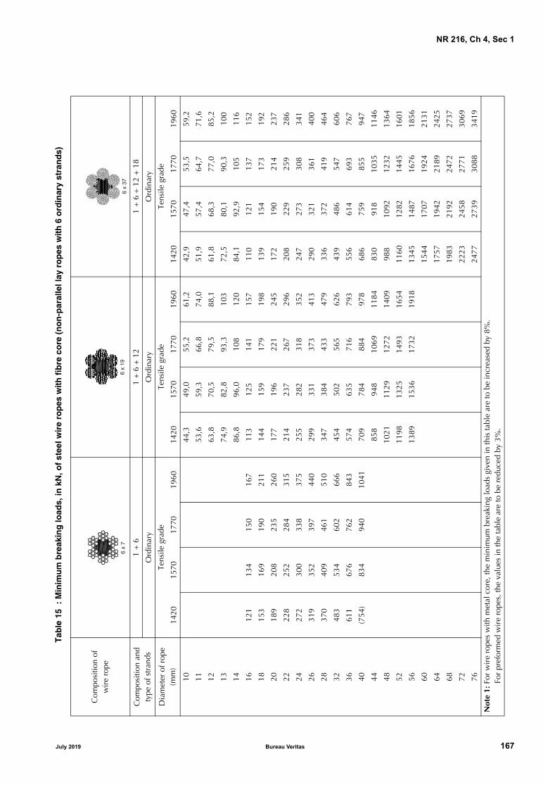
NR 216, Ch 4, Sec 1
Tab
le 1
5 :
Min
imu
m b
reak
ing
load
s, in
kN
, of
stee
l wir
e ro
pes
wit
h f
ibre
co
re (
no
n-p
aral
lel l
ay r
op
es w
ith
6 o
rdin
ary
stra
nd
s)
Com
posi
tion
ofw
ire
rope
Com
posi
tion
and
type
of s
tran
ds1
+ 6
1 +
6 +
12
1 +
6 +
12
+ 1
8
Ord
inar
yO
rdin
ary
Ord
inar
y
Dia
met
er o
f rop
e(m
m)
Tens
ile g
rade
Tens
ile g
rade
Tens
ile g
rade
1420
1570
1770
1960
1420
1570
1770
1960
1420
1570
1770
1960
1044
,349
,055
,261
,242
,947
,453
,559
,2
1153
,659
,366
,874
,051
,957
,464
,771
,6
1263
,870
,579
,588
,161
,868
,377
,085
,2
1374
,982
,893
,310
372
,580
,190
,310
0
1486
,896
,010
812
084
,192
,910
511
6
1612
113
415
016
711
312
514
115
711
012
113
715
2
1815
316
919
021
114
415
917
919
813
915
417
319
2
2018
920
823
526
017
719
622
124
517
219
021
423
7
2222
825
228
431
521
423
726
729
620
822
925
928
6
2427
230
033
837
525
528
231
835
224
727
330
834
1
2631
935
239
744
029
933
137
341
329
032
136
140
0
2837
040
946
151
034
738
443
347
933
637
241
946
4
3248
353
460
266
645
450
256
562
643
948
654
760
6
3661
167
676
284
357
463
571
679
355
661
469
376
7
40(7
54)
834
940
1041
709
784
884
978
686
759
855
947
4485
894
810
6911
8483
091
810
3511
46
4810
2111
2912
7214
0998
810
9212
3213
64
5211
9813
2514
9316
5411
6012
8214
4516
01
5613
8915
3617
3219
1813
4514
8716
7618
56
6015
4417
0719
2421
31
6417
5719
4221
8924
25
6819
8321
9224
7227
37
7222
2324
5827
7130
69
7624
7727
3930
8834
19
Not
e 1:
For
wir
e ro
pes
with
met
al c
ore,
the
min
imum
bre
akin
g lo
ads
give
n in
this
tabl
e ar
e to
be
incr
ease
d by
8%
.
F
or p
refo
rmed
wir
e ro
pes,
the
valu
es in
the
tabl
e ar
e to
be
redu
ced
by 3
%.
6 x
76
x 19
6 x
37
July 2019 Bureau Veritas 167

NR 216, Ch 4, Sec 1
Table
16
: M
inim
um
bre
akin
g lo
ads,
in k
N, o
f st
eel w
ire
rop
es w
ith
fib
re c
ore
(n
on
par
alle
l lay
ro
pes
wit
h 6
ord
inar
y st
ran
ds)
Com
posi
tion
ofw
ire
rope
Com
posi
tion
and
type
of s
tran
ds1
+ 6
+ 1
2 +
18
+ 2
4Fi
bre
core
+ 9
+ 1
5Fi
bre
core
+ 1
2 +
18
Ord
inar
yO
rdin
ary
Ord
inar
y
Dia
met
er o
f rop
e(m
m)
Tens
ile g
rade
Tens
ile g
rade
Tens
ile g
rade
1420
1570
1770
1960
1420
1570
1770
1960
1420
1570
1770
1960
1039
,844
,049
,654
,9
1148
,153
,260
,066
,4
1257
,363
,371
,479
,0
1367
,274
,383
,892
,761
,067
,476
,084
,1
1477
,986
,297
,110
870
,778
,288
,197
,6
1610
211
312
714
092
,310
211
512
7
1812
914
216
117
811
712
914
616
1
2016
518
220
522
715
917
619
822
014
416
018
019
9
2219
922
024
827
519
221
324
026
617
519
321
824
1
2423
726
229
632
722
925
328
531
620
823
025
928
7
2627
830
834
738
426
929
733
537
124
427
030
433
7
2832
335
740
244
631
234
538
943
028
331
335
239
0
3242
246
652
658
240
745
050
756
236
940
846
051
0
3653
459
066
573
751
557
064
271
146
751
758
364
5
4065
972
882
190
963
670
379
387
857
763
871
979
7
4479
788
199
411
0077
085
195
910
6269
877
287
096
4
4894
910
4911
8313
1091
610
1311
4212
6483
191
910
3611
47
5211
1412
3113
8815
3710
7511
8913
4014
8497
510
7812
1613
46
5612
9114
2816
1017
8312
4713
7915
5417
2111
3112
5114
1015
61
6014
8216
3918
4820
4614
3115
8317
8419
7612
9814
3616
1817
92
6416
8718
6521
0223
2816
2918
0120
3022
4814
7716
3318
4120
39
6819
0421
0523
7326
2816
6818
4420
7923
02
7221
3523
6026
6129
4718
7020
6723
3125
81
7623
7926
3029
6532
8320
8323
0325
9728
76
Not
e 1:
For
wir
e ro
pes
with
met
al c
ore,
the
min
imum
bre
akin
g lo
ads
give
n in
this
tabl
e ar
e to
be
incr
ease
d by
8%
.
F
or p
refo
rmed
wir
e ro
pes,
the
valu
es in
the
tabl
e ar
e to
be
redu
ced
by 3
%.
6 x
616
x 24
6 x
30
168 Bureau Veritas July 2019

NR 216, Ch 4, Sec 1
Tab
le 1
7 :
Min
imu
m b
reak
ing
load
s, in
kN
, of
stee
l wir
e ro
pes
wit
h f
ibre
co
re (
War
rin
gto
n a
nd
War
rin
gto
n-S
eale
lay
rop
es w
ith
6 s
tran
ds)
Com
posi
tion
ofw
ire
rope
Com
posi
tion
and
type
of s
tran
ds1
+ 6
+ (6
+ 6
)C
ompo
sitio
n of
type
1 +
n +
(n +
n) +
2n
1 +
6 +
9 +
(9 +
9) +
18
n =
5n
= 6
n =
7n
= 8
War
ring
ton
War
ring
ton
- Se
ale
War
ring
ton
- Se
ale
Dia
met
er o
f rop
e(m
m)
Tens
ile g
rade
Tens
ile g
rade
Tens
ile g
rade
1420
1570
1770
1960
1420
1570
1770
1960
1420
1570
1770
1970
1046
,951
,858
,464
,711
56,7
62,7
70,7
78,3
1267
,774
,884
,493
,467
,574
,684
,193
,113
79,4
87,8
99,0
110
79,2
87,6
98,7
109
1492
,110
211
512
791
,810
211
412
716
120
133
150
166
120
133
150
166
1815
216
819
021
015
216
818
921
020
188
208
234
260
187
207
234
259
169
187
211
234
2222
725
228
431
422
725
128
331
320
522
625
528
324
271
299
337
374
270
298
336
373
244
269
304
336
2631
835
139
643
931
735
039
543
728
631
635
739
528
368
407
459
509
367
406
458
507
332
367
414
458
3248
153
260
066
448
053
159
866
243
347
954
059
836
609
673
759
841
607
671
757
838
548
606
684
757
4075
283
193
710
3875
082
993
510
3567
774
984
493
544
910
1006
1134
1256
907
1003
1131
1252
819
906
1021
1131
4810
8311
9713
5014
9510
8011
9413
4614
9097
510
7812
1513
4652
1267
1401
1579
1749
1144
1265
1426
1579
5614
7016
2518
3220
2813
2714
6716
5418
3260
1687
1865
2103
2328
1523
1684
1899
2103
6419
1921
2223
9226
4917
3319
1621
6023
9268 72 76
Not
e 1:
For
wir
e ro
pes
with
met
al c
ore,
the
min
imum
bre
akin
g lo
ads
give
n in
this
tabl
e ar
e to
be
incr
ease
d by
8%
.
F
or p
refo
rmed
wir
e ro
pes,
the
valu
es in
the
tabl
e ar
e to
be
redu
ced
by 3
%.
6 x
196
x 26
6 x
316
x 36
6 x
416
x 52
July 2019 Bureau Veritas 169

NR 216, Ch 4, Sec 1
Table
18
: M
inim
um
bre
akin
g lo
ads,
in k
N, o
f st
eel w
ire
rop
es w
ith
fib
re c
ore
(S
eale
lay
rop
es w
ith
6 s
tran
ds)
Com
posi
tion
ofw
ire
rope
Com
posi
tion
and
type
of s
tran
ds1
+ 9
+ 9
1 +
(6 +
6 F
) + 1
21
+ 6
+ 9
+ 9
1 +
6 +
15+
15
Seal
e (
1)Se
ale
Seal
e
Dia
met
er o
f rop
e(m
m)
Tens
ile g
rade
Tens
ile g
rade
Tens
ile g
rade
1420
1570
1770
1960
1420
1570
1770
1960
1420
1570
1770
1960
1047
,052
,058
,664
,911
56,9
62,9
70,9
78,5
1267
,774
,884
,493
,413
79,4
87,8
99,0
110
1492
,110
211
512
716
120
133
150
166
1815
216
819
021
014
816
418
520
420
188
208
234
260
183
202
228
252
2222
725
228
431
422
124
527
630
524
271
299
337
374
263
291
328
364
268
297
334
370
2631
835
139
643
930
934
238
542
731
534
839
243
528
368
407
459
509
358
396
447
495
365
404
455
504
3248
153
260
066
446
851
858
464
647
752
759
465
836
609
673
759
841
593
655
739
818
604
667
752
833
4075
283
193
710
3873
280
991
210
1074
582
492
910
2944
885
979
1103
1222
902
997
1124
1245
4810
5311
6513
1314
5410
7311
8613
3814
8152
1236
1367
1541
1707
1259
1392
1570
1738
5614
6116
1518
2120
1660
1677
1854
2090
2314
6419
0821
0923
7826
3368 72 76
Not
e 1:
For
wir
e ro
pes
with
met
al c
ore,
the
min
imum
bre
akin
g lo
ads
give
n in
this
tabl
e ar
e to
be
incr
ease
d by
8%
.
F
or p
refo
rmed
wir
e ro
pes,
the
valu
es in
the
tabl
e ar
e to
be
redu
ced
by 3
%.
(1)
Min
imum
bre
akin
g lo
ads
as in
dica
ted
corr
espo
nd to
6 x
19
Seal
e la
y ro
pes.
For
6 x
19 F
Sea
le F
iller
lay
rope
s, s
omet
imes
cal
led
6 x
25 F
iller
, the
giv
en v
alue
s ar
e to
be
incr
ease
d by
2%
.
6 x
19 F
(**
)6
x 19
6 x
25
6 x
37
170 Bureau Veritas July 2019

NR 216, Ch 4, Sec 1
Tab
le 1
9 :
Min
imu
m b
reak
ing
load
s, in
kN
, of
stee
l wir
e ro
pes
wit
h f
ibre
co
re (
rop
es w
ith
8 s
tran
ds
and
no
n-r
ota
tin
g r
op
es)
Com
posi
tion
ofw
ire
rope
Com
posi
tion
and
type
of s
tran
ds1
+ 9
+ 9
1 +
(6 +
6 F
) + 1
21
+ 6
1 +
6Se
ale
(1)
Ord
inar
yO
rdin
ary
Dia
met
er o
f rop
e(m
m)
Tens
ile g
rade
Tens
ile g
rade
Tens
ile g
rade
1420
1570
1770
1960
1420
1570
1770
1960
1420
1570
1770
1960
1041
,646
,051
,957
,446
,651
,558
,164
,311
50,3
55,7
62,8
69,5
56,4
62,3
70,2
77,8
1259
,966
,274
,782
,767
,174
,283
,692
,613
70,3
77,7
87,6
97,1
78,7
87,0
98,1
109
1481
,590
,210
211
391
,310
111
412
616
107
118
133
147
119
132
149
165
116
128
144
160
1813
514
916
818
615
116
718
820
814
616
218
220
220
166
184
207
230
186
206
232
257
181
200
225
249
2220
122
325
127
822
524
928
131
121
924
227
230
224
240
265
299
331
268
297
334
370
260
288
324
359
2628
131
135
138
831
534
839
243
530
533
738
042
128
326
361
407
450
365
404
455
504
354
391
441
489
3242
647
153
158
844
752
759
465
846
251
157
663
836
539
596
672
744
604
667
752
833
585
647
729
808
4074
582
492
910
2972
279
990
199
744
902
997
1124
1245
874
967
1090
1207
4810
7311
8613
3814
8110
4011
5012
9714
3652
1259
1392
1570
1738
1221
1350
1522
1685
5614
1615
6617
6519
5560
1626
1797
2026
2244
6418
5020
4523
0525
5368
2088
2309
2603
2882
7223
4125
8829
1832
3176
2608
2884
3251
3600
Not
e 1:
For
wir
e ro
pes
with
met
al c
ore,
the
min
imum
bre
akin
g lo
ads
give
n in
this
tabl
e ar
e to
be
incr
ease
d by
8%
.
F
or p
refo
rmed
wir
e ro
pes,
the
valu
es in
the
tabl
e ar
e to
be
redu
ced
by 3
%.
(1)
Min
imum
bre
akin
g lo
ads
as in
dica
ted
corr
espo
nd to
8 x
19
Seal
e la
y ro
pes.
For
8 x
19 F
Sea
le F
iller
lay
rope
s, s
omet
imes
cal
led
8 x
25 F
iller
, the
giv
en v
alue
s ar
e to
be
incr
ease
d by
2%
.
8x
198
x 19
F����������
34 x
7 o
r 36
x 7
July 2019 Bureau Veritas 171

NR 216, Ch 4, Sec 1
4.4.3 Breaking test on full size specimensSamples and testing procedures are to be in compliancewith recognised standards, such as ISO 3108.
The test sample is to be long enough to obtain a clear dis-tance, between the grips of the testing machine, at leastequal to 30 times the diameter of the ropes, with a mini-mum of 600 mm.
The above clear distance may be reduced to 300 mm if thediameter is less than 6 mm.
During the test, when the applied load has exceededapproximately 80% of the required breaking load, the loadis to be applied slowly and steadily (about 10 N/mm2 persecond).
The breaking load is to be not less than the minimum valuerequired in Tab 15 to Tab 19 for each type and diameter ofrope.
The result of the test may be disregarded if the specimenbreaks outside the gauge length, in particular in way of theterminals.
4.4.4 Breaking test on individual wires
As an alternative, when the breaking test on full size speci-mens cannot be performed, the breaking strength of therope may be determined, in agreement with the Surveyor, asthe sum of the actual breaking strengths determined on theindividual wires, multiplied by the factor K (realisation fac-tor) applicable in relation to the type and construction ofthe rope.
The factor K applicable to types of rope in current use isgiven in Tab 20 (for other types of ropes, the factor K isstated by the Society in each case).
Table 20 : Realisation factor K
Construction of rope (1)
Construction of strands (2)
Type of ropestranding (3)
Realisation factor K (4)
Fibre core (5) Metal core (6)
6 x 7 1 + 6 O 0,90 0,870
6 x 19 1 + 6 + 12 O 0,87 0,835
6 x 19 1 + 9 + 9 S 0,87 0,835
6 x 19 F (7) 1 + (6 + 6 F) + 12 S - F 0,87 0,835
6 x 19 1 + 6 + (6 + 6) W 0,87 0,835
6 x 24 fibre core + 9 + 15 O 0,87 −
6 x 25 1 + 6 + 9 + 9 S 0,86 0,825
6 x 26 1 + 5 + (5 + 5) + 10 W - S 0,85 0,815
6 x 30 fibre core + 12 + 18 O 0,87 −
6 x 31 1 + 6 + (6 + 6) + 12 W - S 0,85 0,815
6 x 36 1 + 7 + (7 + 7) + 14 W - S 0,85 0,815
6 x 37 1 + 6 + 12 + 18 O 0,85 0,815
6 x 37 1 + 6 + 15 + 15 S 0,85 0,815
6 x 41 1 + 8 + (8 + 8) + 16 W - S 0,85 0,815
6 x 52 1 + 6 + 9 + (9 + 9) + 18 W - S 0,81 0,775
6 x 61 1 + 6 + 12 + 18 + 24 O 0,81 0,775
8 x 19 1 + 9 + 9 S 0,83 −
8 x 19 F (7) 1 + (6 + 6 F) + 12 S - F 0,83 −
17 x 7 1 + 6 O 0,84 0,815
18 x 7 1 + 6 O 0,84 0,815
34 x 7 1 + 6 O 0,80 0,790
36 x 7 1 + 6 O 0,80 0,790
(1) The first figure gives the number of strands, the second the number of wires in each strand.(2) The figures give the number of wires for each layer; the figures in brackets are relevant to wires of the same layer but of two dif-
ferent diameters. The letter F indicates filler wires.(3) The type of rope stranding indications are as follows:
• O: ordinary strands (non-parallel wires);• S, S-F, W and W-S (strands with parallel wires): designate Seale, Seale-Filler, Warrington and Warrington-Seale strandings,
respectively.(4) The coefficient K is to be reduced by 3% for preformed ropes.(5) The fibre core is not considered in the breaking load of the rope.(6) The metal core consists of an independent rope (in general 6x7 with centre strand of 7 wires); it may, however, consist of a sin-
gle strand for wire ropes of 6x7 and 6x19 wires with ordinary strands.(7) 6x19 and 8x19 Filler wire ropes are sometimes designated by 6x25 Filler and 8x25 Filler, respectively.
172 Bureau Veritas July 2019

NR 216, Ch 4, Sec 1
The tensile test is to be performed on at least 10% of thewires of the rope to be tested, with a minimum of two wiresper strand.
The wires tested are to satisfy the tensile requirements spec-ified for the wires and the total breaking load of the n wirestested multiplied by the ratio N/n (where N is the total num-ber of wires of the rope) and by the factor K (depending onthe type of the rope) is to be not less than the minimumvalue specified by the recognised standard applied.
The acceptance of the check of the breaking load of therope by means of tensile tests on individual wires is, in gen-eral, subject to a number of proof tests on samples of fullsize ropes which are representative of the production forcomparison purposes.
4.4.5 Check of the strength of individual wires
This check, consisting of tensile tests on individual wires, isperformed only when required by the Surveyor as a checkon the base materials employed.
4.4.6 Torsion test and coiling test on individual wires
In general only one of these tests is to be performed.
The tests are to be carried out on specimens obtained aftergalvanising from at least 5% of the number of wires taken atrandom in several strands with a minimum of 6 wires and amaximum of 10 wires for each diameter.
• Torsion test
The gauge length of the wire specimens, measuredbetween the end terminals, is to be 100 times the wirediameter, but need not exceed 300 mm for wire diame-ters above 3 mm.
The wire is to be well clamped at the ends and wellstrained, e.g., under an axial load not exceeding 2% ofits nominal breaking load.
The wire is then subjected to torsion until fractureoccurs; the torque is to be applied as uniformly as possi-ble, at the approximate rate of 60 - 70 revolutions perminute. The minimum required number of twists with-out fracture is specified in Tab 21.
The torsion test is not required for wires of diameterlower than 0,5 mm.
• Coiling test
The test consists of coiling a specimen of wire of suffi-cient length 8 times, in closed coils, around a cylindri-cal mandrel having a diameter equal to that of the wire;the wire is to be subsequently uncoiled and straight-ened.
After having been coiled, the zinc coating is not to showany sign of significant cracks or laminations. In the sub-sequent uncoiling and straightening, fracture of the wireis not to occur.
4.4.7 Checks of the zinc mass
The mass of zinc coating per unit area is required to bechecked in accordance with a recognised standard.
The results of this test are to demonstrate compliance withthe minimum required values specified in Tab 22.
4.4.8 Check of the uniformity and continuity of the zinc coating
This test is performed when required by the Surveyor as aproduction check. It applies only to wires of diameter ≥1mm if galvanised of class A and of diameter ≥ 0,6 mm ifgalvanised of class B.
The tests are to be carried out on specimens obtained aftergalvanising from at least 5% of the number of wires taken atrandom in several strands with a minimum of 6 wires and amaximum of 10 wires for each diameter.
Unless otherwise specified, the test is performed by sub-merging a specimen in a water solution of pure cristallinecopper sulphate (Cu SO4 · 5 H2O) containing at least 360gof salt per litre of distilled water at a temperature of 20°C±2°C.
The specimen is to be immersed for a length of at least 80mm and is to be maintained in vertical position.
Tab 22 shows the minimum number of one-minute submer-sions, in relation to the wire diameter and galvanising class.After each submersion, the specimen is to be rinsed in run-ning water so as to wash away unbonded copper deposits.
The test is regarded as satisfactory when the specimen doesnot show (beyond 25 mm from the immersed end) indica-tions of bonded copper deposits, which would mean locallack of zinc coating on the steel surface.
Table 21 : Torsion test for wires - Minimum number of twists
Diameter d(mm)
Galvanising class A Galvanising class B
Tensile grade Tensile grade
1420 1560 1770 1420 1560 1770 1960
d < 1,3 19 18 17 31 29 26 18
1,3 ≤ d < 1,8 18 17 16 30 28 25 17
1,8 ≤ d < 2,3 18 17 16 28 26 25 16
2,3 ≤ d < 3,0 16 14 12 26 24 22 15
3,0 ≤ d < 3,5 14 12 10 24 22 20 13
3,5 ≤ d < 3,7 12 10 8 20 20 18 12
July 2019 Bureau Veritas 173

NR 216, Ch 4, Sec 1
Table 22 : Check of zinc continuity on wire coating
4.5 Identification marking and certification
4.5.1 Upon satisfactory completion of the required testsand examinations, the ropes, packed in the required lengthfor supply, are to be tagged with lead seals stamped with theSociety’s brand and further indications, as necessary foridentification with the respective test certificates.
4.5.2 The certificates are to contain the essential elementsrelevant to the rope characteristics, the results of the testand the stamps and markings mentioned in [4.5.1].
Special marking and certification methods may be agreedupon for supplies by Manufacturers granted the use of analternative testing procedure.
5 Fibre ropes
5.1 Scope
5.1.1 General
The requirements of this Article apply to fibre ropes,intended for towing and mooring lines, emergency towingarrangement, cargo handling gear or similar applications,other than those specified in [5.1.2] [5.1.3].
5.1.2 Single Point Mooring Hawsers
Hawsers intended for mooring oil tankers (single pointmooring) at an offloading buoy are to be made of fibres ofan approved type, as per annex 4 in NI 432, and are to beinspected and tested in accordance with the OCIMF“Guidelines for the purchasing and testing of single pointmooring hawsers”, 2000, under survey by the Society.
5.1.3 Fibre ropes for deep water offshore services
Requirements for the certification of fibre ropes intended foruse as load-bearing components in the stationkeeping sys-tem of a floating offshore unit, or for other offshore deepwa-ter applications, are defined in Guidance Note NI 432Certification of Fibre Ropes for Deepwater Offshore Ser-vices.
5.2 General
5.2.1 Ropes, rope material, rope construction and size areto be in accordance with the ISO standards specified below,or another consistent set of recognised standards acceptedby the Society:
• ISO 9554: Fibre ropes - General specifications
• the ISO product standard proposed by the manufacturerfor the concerned material and construction.
Ropes are to be of the size (reference number, or “nominaldiameter” or circumference) needed to meet the specifiedbreaking strength, or other relevant requirement of theRules.
5.3 Sampling and testing
5.3.1 General
The following examinations and tests, as defined in [5.3.3]to [5.3.5], are to be performed in accordance with the rele-vant provisions of ISO 2307: “Fibre ropes - Determinationof certain physical and mechanical properties”:
• linear density
• breaking strength on a full size sample, or determinationof rope strength from yarn testing, when applicable.
The required tests and examinations are to be performedwith the appropriate machinery, equipment and proce-dures.
The machines for load testing and weighing are to be cali-brated.
5.3.2 Sampling
Acceptance tests are to be performed on each length manu-factured in continuous production, but not less than onceevery 2000 m.
5.3.3 Linear density
The linear density of the rope under the reference tension,measured following the procedure and requirements in ISO2307, is to be in accordance with the value for the specifiedrope size in the applicable product standard.
5.3.4 Breaking test on full size specimen
The breaking strength of the rope is to be verified by testingto destruction a sample of rope, following the procedureand requirements in ISO 2307.
The achieved breaking load is to be recorded, and is to benot less than that given in the applicable product standardfor the specified size, taking into account acceptance crite-ria in ISO 2307.
5.3.5 Breaking test on individual yarns
When the breaking test on full size test pieces cannot beperformed, and subject to agreement by the Society, thebreaking strength is to be obtained by calculation based onbreaking strength tests on yarns, according to the proceduregiven in Annex B of ISO 2307.
Diameter dof galvanised
wire (mm)
Number of one-minute submersions (1)
Class A Class B
0,6 ≤ d < 1,0 − 0,5
1,0 ≤ d < 1,5 1,5 1,0
1,5 ≤ d < 1,9 2,0 1,0
1,9 ≤ d < 2,5 2,0 1,5
2,5 ≤ d < 3,2 2,5 1,5
3,2 ≤ d < 3,7 3,0 2,0
(1) 1,5 submersion means one submersion lasting 1 minutefollowed by another lasting 30 seconds (the same crite-ria applies for the other numbers).
174 Bureau Veritas July 2019

NR 216, Ch 4, Sec 1
This is applicable only to ropes having a breaking strengthabove 250 kN, made from a single fibre material and size,and for those materials and construction where a realisationfactor is given in the standard.
The relevant testing documentation is to include a mentionstating that the breaking strength has been calculated.
5.4 Marking
5.4.1 Upon satisfactory completion of the required testsand examinations, the packed ropes are to tagged with theSociety’s stamp and identification of the inspection certifi-cate issued by the Society.
July 2019 Bureau Veritas 175

NR 216, Ch 4, Sec 2
SECTION 2 OFFSHORE MOORING CHAIN CABLES AND ACCESSORIES
1 General requirements
1.1 Scope
1.1.1 These requirements apply to offshore units and singlepoint moorings contracted for construction on or after1st July 2017 and when the application for certification ofmooring chains and accessories is dated on or after 1st July2017.
1.1.2 The requirements of this Section apply to the materi-als, design, manufacture and testing of offshore mooringchain and accessories intended to be used for applicationsuch as: mooring of mobile offshore units, mooring of float-ing production units, mooring of offshore loading systemsand mooring of gravity based structures during fabrication.
Mooring equipment covered are common stud and studlesslinks, connecting common links (splice links), enlargedlinks, end links, detachable connecting links (shackles), endshackles, subsea connectors, swivels and swivel shackles.
Studless link chain is normally deployed only once, beingintended for long-term permanent mooring systems withpre-determined design life.
Each grade is to be individually approved. Approval for ahigher grade does not constitute approval of a lower grade.If it is demonstrated to the satisfaction of the Society that thehigher and lower grades are produced to the same manu-facturing procedure using the same chemistry and heattreatment, consideration will be given to qualification of alower grade by a higher. The parameters applied duringqualification are not to be modified during production.
1.2 Chain grades
1.2.1 Depending on the nominal tensile strength of thesteels used for manufacture, chains are to be subdividedinto five grades, i.e.: QR3, QR3S, QR4, QR4S and QR5.
Manufacturers propriety specifications for QR4S and QR5may vary subject to design conditions and the acceptanceof the Society.
Each grade is to be individually approved. Approval for ahigher grade does not constitute approval of a lower grade.
1.3 Approval of chain manufacturers
1.3.1 Offshore mooring chains are to be manufacturedonly by works approved by the Society. For this purposeapproval tests are to be carried out, the scope of which is toinclude proof and breaking load tests, measurements andmechanical tests including fracture mechanics tests.
1.3.2 Manufacturers are to submit for review and approvalthe sequence of operations from receiving inspection toshipment and details of the following manufacturing pro-cesses:
a) bar heating and bending including method, tempera-tures, temperature control and recording
b) flash welding including current, force, time and dimen-sional variables as well as control and recording ofparameters, maintenance procedure and programme forwelding machine
c) flash removal including method and inspection
d) stud insertion method, for stud link chain
e) heat treatment including furnace types, means of speci-fying, controlling and recording of temperature andchain speed and allowable limits, quenching bath andagitation, cooling method after exit
f) proof and break loading including method/machine,means of horizontal support (if applicable), method ofmeasurement and recording
g) non-destructive examination procedures
h) the manufacturer’s surface quality requirement of moor-ing components is to be submitted
i) the manufacturer’s procedure for removing and replac-ing defective links without heat treatment of the entirechain.
1.3.3 For initial approval CTOD tests are to be carried outon the particular mooring grade of material. CTOD tests areto be done in accordance with a recognized standard suchas BS 7448 Parts 1 & BS EN ISO 15653:2010.
The CTOD test piece is to be a standard 2 x 1 single edgenotched bend piece, test location as shown in Fig 1. Thenotch of the CTOD specimen is to be located as close to thesurface as practicable.
The minimum test piece size shall be 50 mm x 25 mm forchain diameters less than 120 mm, and 80 mm x 40 mm fordiameters 120 mm and above. CTOD specimens are to betaken from both the side of the link containing the weld andfrom the opposite side. Three links are to be selected fortesting, a total of 6 CTOD specimens. The tests are to betaken at −20°C and the lowest CTOD of each set of 3 speci-mens shall meet the minimum values indicated in Tab 1.
176 Bureau Veritas July 2019

NR 216, Ch 4, Sec 2
Table 1 : Minimum CTOD test values for chain type
Figure 1 : Location of CTOD test specimens
1.3.4 Calibration of furnaces shall be verified by measure-ment and recording of a calibration test piece.
The manufacturer shall submit a procedure for calibrationof furnaces and temperature uniformity surveys which shallinclude the following requirements:
a) the temperature uniformity of furnaces is to be surveyedwhenever approval of manufacturer is requested and atleast annually during normal operating conditions
b) a calibration test piece with dimensions equivalent tothe maximum size of link manufactured, and, instru-mented with two thermocouples is to be used. Onethermocouple shall be attached to the surface of thestraight part and one thermocouple shall be imbeddedin a drilled hole located at the mid thickness position ofthe straight part of the calibration test piece
c) furnaces are to be checked by conveying the calibrationtest piece through the furnaces at representative travelspeed
d) the time-temperature curves shall show that the tem-peratures throughout the cross section and the soakingtimes are within specified limits as given in the heattreatment procedure.
1.3.5 For QR4S and QR5 chain and accessories, prior toapproval, the manufacturer is to have undertaken experi-mental tests or have relevant supporting data to develop thechain and accessory material.
The tests and data may include: fatigue tests, hot ductilitytests (no internal flaws are to develop whilst bending in thelink forming temperature range), welding parameterresearch, heat treatment study, strain age resistance, temperembrittlement study, stress corrosion cracking (SCC) dataand hydrogen embrittlement (HE) study, using low strain testpieces in hydrated environments. Reports indicated theresults of experimental tests are to be submitted.
1.4 Approval of quality system at chain and accessory manufacturers
1.4.1 Chain and accessory manufacturers are to have adocumented and effective quality system approved by theSociety. The provision of such a quality system is required inaddition to, and not in lieu of, the witnessing of tests by aSurveyor as specified in this Section.
1.5 Approval of steel mills - Rolled bar
1.5.1 Bar materials intended for chain and accessories areto be manufactured only by works approved by the Society.The approval is limited to a nominated supplier of bar mate-rial. If a chain manufacturer wishes to use material from anumber of suppliers, separate approval tests must be carriedout for each supplier.
1.5.2 Approval will be given only after successful testing ofthe completed chain.
Each grade is to be individually approved. Approval for ahigher grade does not constitute approval of a lower grade.If it is demonstrated to the satisfaction of the Society that thehigher and lower grades are produced to the same manu-facturing procedure using the same chemistry and heattreatment, consideration will be given to qualification of alower grade by a higher. The parameters applied duringqualification are not to be modified during production.
The approval will normally be limited up to the maximumdiameter equal to that of the chain diameter tested. The roll-ing reduction ratio is to be recorded and is to be at least 5:1.The rolling reduction ratio used in production can behigher, but should not be lower than that qualified.
Chain typeQR3, in mm QR3S, in mm QR4, in mm QR4S and QR5, in mm
BM WM BM WM BM WM BM WM
Stud link 0,20 0,10 0,22 0,11 0,24 0,12 0,26 0,13
Studless 0,20 0,14 0,22 0,15 0,24 0,16 0,26 0,17
Weld side Non-weld side
July 2019 Bureau Veritas 177
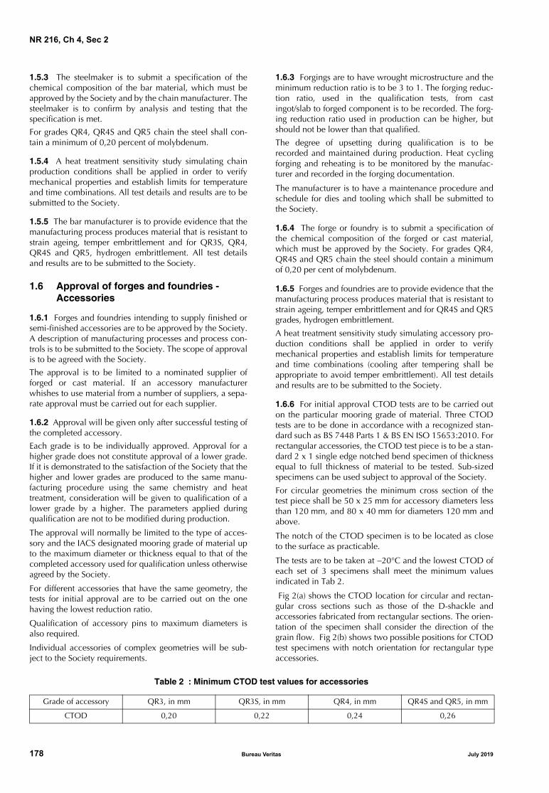
NR 216, Ch 4, Sec 2
1.5.3 The steelmaker is to submit a specification of thechemical composition of the bar material, which must beapproved by the Society and by the chain manufacturer. Thesteelmaker is to confirm by analysis and testing that thespecification is met.
For grades QR4, QR4S and QR5 chain the steel shall con-tain a minimum of 0,20 percent of molybdenum.
1.5.4 A heat treatment sensitivity study simulating chainproduction conditions shall be applied in order to verifymechanical properties and establish limits for temperatureand time combinations. All test details and results are to besubmitted to the Society.
1.5.5 The bar manufacturer is to provide evidence that themanufacturing process produces material that is resistant tostrain ageing, temper embrittlement and for QR3S, QR4,QR4S and QR5, hydrogen embrittlement. All test detailsand results are to be submitted to the Society.
1.6 Approval of forges and foundries - Accessories
1.6.1 Forges and foundries intending to supply finished orsemi-finished accessories are to be approved by the Society.A description of manufacturing processes and process con-trols is to be submitted to the Society. The scope of approvalis to be agreed with the Society.
The approval is to be limited to a nominated supplier offorged or cast material. If an accessory manufacturerwhishes to use material from a number of suppliers, a sepa-rate approval must be carried out for each supplier.
1.6.2 Approval will be given only after successful testing ofthe completed accessory.
Each grade is to be individually approved. Approval for ahigher grade does not constitute approval of a lower grade.If it is demonstrated to the satisfaction of the Society that thehigher and lower grades are produced to the same manu-facturing procedure using the same chemistry and heattreatment, consideration will be given to qualification of alower grade by a higher. The parameters applied duringqualification are not to be modified during production.
The approval will normally be limited to the type of acces-sory and the IACS designated mooring grade of material upto the maximum diameter or thickness equal to that of thecompleted accessory used for qualification unless otherwiseagreed by the Society.
For different accessories that have the same geometry, thetests for initial approval are to be carried out on the onehaving the lowest reduction ratio.
Qualification of accessory pins to maximum diameters isalso required.
Individual accessories of complex geometries will be sub-ject to the Society requirements.
1.6.3 Forgings are to have wrought microstructure and theminimum reduction ratio is to be 3 to 1. The forging reduc-tion ratio, used in the qualification tests, from castingot/slab to forged component is to be recorded. The forg-ing reduction ratio used in production can be higher, butshould not be lower than that qualified.
The degree of upsetting during qualification is to berecorded and maintained during production. Heat cyclingforging and reheating is to be monitored by the manufac-turer and recorded in the forging documentation.
The manufacturer is to have a maintenance procedure andschedule for dies and tooling which shall be submitted tothe Society.
1.6.4 The forge or foundry is to submit a specification ofthe chemical composition of the forged or cast material,which must be approved by the Society. For grades QR4,QR4S and QR5 chain the steel should contain a minimumof 0,20 per cent of molybdenum.
1.6.5 Forges and foundries are to provide evidence that themanufacturing process produces material that is resistant tostrain ageing, temper embrittlement and for QR4S and QR5grades, hydrogen embrittlement.
A heat treatment sensitivity study simulating accessory pro-duction conditions shall be applied in order to verifymechanical properties and establish limits for temperatureand time combinations (cooling after tempering shall beappropriate to avoid temper embrittlement). All test detailsand results are to be submitted to the Society.
1.6.6 For initial approval CTOD tests are to be carried outon the particular mooring grade of material. Three CTODtests are to be done in accordance with a recognized stan-dard such as BS 7448 Parts 1 & BS EN ISO 15653:2010. Forrectangular accessories, the CTOD test piece is to be a stan-dard 2 x 1 single edge notched bend specimen of thicknessequal to full thickness of material to be tested. Sub-sizedspecimens can be used subject to approval of the Society.
For circular geometries the minimum cross section of thetest piece shall be 50 x 25 mm for accessory diameters lessthan 120 mm, and 80 x 40 mm for diameters 120 mm andabove.
The notch of the CTOD specimen is to be located as closeto the surface as practicable.
The tests are to be taken at −20°C and the lowest CTOD ofeach set of 3 specimens shall meet the minimum valuesindicated in Tab 2.
Fig 2(a) shows the CTOD location for circular and rectan-gular cross sections such as those of the D-shackle andaccessories fabricated from rectangular sections. The orien-tation of the specimen shall consider the direction of thegrain flow. Fig 2(b) shows two possible positions for CTODtest specimens with notch orientation for rectangular typeaccessories.
Table 2 : Minimum CTOD test values for accessories
Grade of accessory QR3, in mm QR3S, in mm QR4, in mm QR4S and QR5, in mm
CTOD 0,20 0,22 0,24 0,26
178 Bureau Veritas July 2019
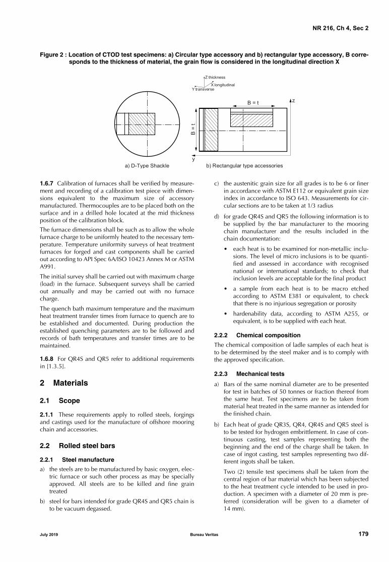
NR 216, Ch 4, Sec 2
Figure 2 : Location of CTOD test specimens: a) Circular type accessory and b) rectangular type accessory, B corre-sponds to the thickness of material, the grain flow is considered in the longitudinal direction X
1.6.7 Calibration of furnaces shall be verified by measure-ment and recording of a calibration test piece with dimen-sions equivalent to the maximum size of accessorymanufactured. Thermocouples are to be placed both on thesurface and in a drilled hole located at the mid thicknessposition of the calibration block.
The furnace dimensions shall be such as to allow the wholefurnace charge to be uniformly heated to the necessary tem-perature. Temperature uniformity surveys of heat treatmentfurnaces for forged and cast components shall be carriedout according to API Spec 6A/ISO 10423 Annex M or ASTMA991.
The initial survey shall be carried out with maximum charge(load) in the furnace. Subsequent surveys shall be carriedout annually and may be carried out with no furnacecharge.
The quench bath maximum temperature and the maximumheat treatment transfer times from furnace to quench are tobe established and documented. During production theestablished quenching parameters are to be followed andrecords of bath temperatures and transfer times are to bemaintained.
1.6.8 For QR4S and QR5 refer to additional requirementsin [1.3.5].
2 Materials
2.1 Scope
2.1.1 These requirements apply to rolled steels, forgingsand castings used for the manufacture of offshore mooringchain and accessories.
2.2 Rolled steel bars
2.2.1 Steel manufacture
a) the steels are to be manufactured by basic oxygen, elec-tric furnace or such other process as may be speciallyapproved. All steels are to be killed and fine graintreated
b) steel for bars intended for grade QR4S and QR5 chain isto be vacuum degassed.
c) the austenitic grain size for all grades is to be 6 or finerin accordance with ASTM E112 or equivalent grain sizeindex in accordance to ISO 643. Measurements for cir-cular sections are to be taken at 1/3 radius
d) for grade QR4S and QR5 the following information is tobe supplied by the bar manufacturer to the mooringchain manufacturer and the results included in thechain documentation:
• each heat is to be examined for non-metallic inclu-sions. The level of micro inclusions is to be quanti-fied and assessed in accordance with recognisednational or international standards; to check thatinclusion levels are acceptable for the final product
• a sample from each heat is to be macro etchedaccording to ASTM E381 or equivalent, to checkthat there is no injurious segregation or porosity
• hardenability data, according to ASTM A255, orequivalent, is to be supplied with each heat.
2.2.2 Chemical composition
The chemical composition of ladle samples of each heat isto be determined by the steel maker and is to comply withthe approved specification.
2.2.3 Mechanical tests
a) Bars of the same nominal diameter are to be presentedfor test in batches of 50 tonnes or fraction thereof fromthe same heat. Test specimens are to be taken frommaterial heat treated in the same manner as intended forthe finished chain.
b) Each heat of grade QR3S, QR4, QR4S and QR5 steel isto be tested for hydrogen embrittlement. In case of con-tinuous casting, test samples representing both thebeginning and the end of the charge shall be taken. Incase of ingot casting, test samples representing two dif-ferent ingots shall be taken.
Two (2) tensile test specimens shall be taken from thecentral region of bar material which has been subjectedto the heat treatment cycle intended to be used in pro-duction. A specimen with a diameter of 20 mm is pre-ferred (consideration will be given to a diameter of14 mm).
a) D-Type Shackle b) Rectangular type accessories
B =
t
B = t z
y
Z
YX
thickness
longitudinaltransverse
July 2019 Bureau Veritas 179

NR 216, Ch 4, Sec 2
One of the specimen is to be tested within a maximumof 3 hours after machining (for a 14 mm diameter speci-men, the time limit is 1½ hour). Where this is not possi-ble, the specimen is to be immediately cooled to −60°Cafter machining and kept at that temperature for a maxi-mum period of 5 days.
The second specimen is to be tested after baking at250°C for 4 hours, alternatively 2 hours for 14 mmdiameter specimen.
A slow strain rate < 0,0003 s−1 must be used during theentire test, until fracture occurs (this is approximately 10minutes for a 20 mm diameter specimen).
Tensile strength, elongation and reduction of area are tobe reported. The requirement for the test is:
Z1 / Z2 ≥ 0,85
where:
Z1 : Reduction of area without baking
Z2 : Reduction of area after baking.
If the requirement Z1 / Z2 ≥ 0,85 is not met, the barmaterial may be subjected to a hydrogen degassingtreatment after agreement with the Society. New testsshall be performed after degassing.
c) For all grades, one tensile and three Charpy V-notchspecimens are to be taken from each sample selected.The test specimens are to be taken at approx. one-thirdradius below the surface, as shown in Fig 3.
The results of all tests are to be in accordance with theappropriate requirements of Tab 3
d) Re-test requirements for tensile tests are given in Ch 1,Sec 2, [2.3].
e) Re-test requirements for Charpy V-notch impact tests aregiven in Ch 1, Sec 2, [4.4].
f) Failure to meet the requirements will result in rejectionof the batch represented unless it can be clearly attribut-able to improper simulated heat treatment.
Figure 3 : Sampling of steel bars, forgings and castings
Table 3 : Mechanical properties of offshore mooring chain and accessories
GradeYield stress
(N/mm2)minimum (1)
Tensile strength (N/mm2)
minimum (1)
Elongation (%)
minimum
Reduction (3) of area (%) minimum
Charpy V-notch impact tests
Test temperature (°C) (2)
Average energy J minimum
Average energy flash weld J minimum
QR3 410 690 17 50 0−20
6040
5030
QR3S 490 770 15 50 0−20
6545
5333
QR4 580 860 12 50 −20 50 36
QR4S (4)
700 960 12 50 −20 56 40
QR5 (4)
760 1000 12 50 −20 58 42
(1) Aim value of yield to tensile ratio: 0,92 max.(2) At the option of the Society, the impact test of grade QR3 and QR3S may be carried out at either 0°C or −20°C.(3) Reduction of area of cast steel is to be for grades QR3 and QR3S: min. 40%, for QR4, QR4S and QR5: min. 35%, see [2.4.4].(4) Aim maximum hardness is HB330 for QR4S and HB340 for QR5.
Specimen for notchedbar impact test
Tensilespecimen
r/3
r/3
Alternatively the 3 CVN test pieces maybe taken in series at one location of r/3
180 Bureau Veritas July 2019

NR 216, Ch 4, Sec 2
2.2.4 Tolerances on dimensions
The diameter and roundness shall be within the tolerancesspecified in Tab 4, unless otherwise agreed.
Table 4 : Tolerances on dimensions of bar stock
2.2.5 Non-destructive examination and repair
Non-destructive examination is to be performed in accor-dance with recognized standards such as those indicatedbelow or others recognized standards:
a) magnetic particle testing (MT) of bars:
• ASTM E1444 and ISO 9934
b) magnetic leakage flux testing (MLFT):
• JIS Z2319
c) eddy current testing (ET) of bars:
• ISO 15549.
Non-destructive examination procedures, together withrejection/acceptance criteria are to be submitted to theSociety.
Manufacturer shall prepare written procedures for NDE.NDE personnel shall be qualified and certified according toISO 9712, ACCP or equivalent. Personnel qualification toan employer or responsible agency based qualificationscheme as SNT-TC-1A may be accepted if the employer’swritten practice is reviewed and found acceptable and theLevel III is ASNT Level III, ISO 9712 Level III or ACCP pro-fessional Level III and certified in the applicable method.NDE operators shall be qualified to at least level II.
The manufacturer shall ensure that 100 percent of each barmaterial intended for either chain or fittings is subjected toultrasonic examination at an appropriate stage of the manu-facture to procedures approved by the Society and to theacceptance criteria required. The bars shall be free of pipe,cracks and flakes. If the end length of the delivered bars isnot subject to UT then it must be agreed between the barsupplier and the chain manufacturer of what length of bar isto be removed from the ends. The details are to be docu-mented in the approval of each bar supplier. Phased arrayUT procedures may be applied, subject to approval by theSociety.
The manufacturer shall ensure that 100 percent of each barmaterial is subjected to examination by magnetic particle(MT) or eddy current (ET) or magnetic leakage flux testing(MLFT) methods. The bars shall be free of injurious surfaceimperfections such as seams, laps and rolled-in mill scale.
Provided that their depth is not greater than 1% of the bardiameter, longitudinal discontinuities may be removed bygrinding and blending to a smooth contour.
All bars supplied in a machined (peeled) condition shall be100% visually inspected. The Society may also required10% inspected with magnetic particle testing (MT) or eddycurrent testing (ET) or magnetic leakage flux testing (MLFT),for longitudinal imperfections. The maximum depth of peel-ing is to be agreed and documented in the approval of eachsupplier.
The frequency of NDE may be reduced at the discretion ofthe Society provided it is verified by statistical means thatthe required quality is consistently achieved.
Weld repair of bar is not permitted.
2.2.6 Marking
Each bar is to be stamped with the steel grade designationand the charge number (or a code indicating the chargenumber) on one of the end surfaces. Other marking meth-ods may be accepted subject to agreement.
2.3 Forged steel
2.3.1 Manufacture
a) forged steels used for the manufacture of accessoriesmust be in compliance with approved specificationsand the submitted test reports approved by the Society.Steel is to be manufactured by basic oxygen, electricfurnace or such other process as may be speciallyapproved. All steel is to be killed and fine grain treated.
b) steels for forgings intended for QR4S and QR5 chain isto be vacuum degassed
c) the austenitic grain size for all steel grades is to be 6 orfiner in accordance with ASTM E112 or equivalent grainsize index in accordance to ISO 643. Measurements forcircular sections are to be taken at 1/3 radius. Measure-ments for non-circular sections are to be taken at 1/4t
d) for steels intended for QR4S and QR5 accessories thefollowing information is to be supplied by the steelmanufacturer to the mooring accessory manufacturerand the results included in the accessory documenta-tion:
• each heat is to be examined for non-metallic inclu-sions. The level of micro inclusions is to be quanti-fied and assessed in accordance with recognisednational or international standards; to check thatinclusion levels are acceptable for the final product
• a sample from each heat is to be macro etchedaccording to ASTM E381 or equivalent, to checkthat there is no injurious segregation or porosity
• hardenability data, according to ASTM A255, orequivalent, is to be supplied with each heat.
2.3.2 Chemical composition
The chemical composition of ladle samples of each heat isto be determined by the steel maker and is to comply withthe approved specification.
Nominaldiameter (mm)
Tolerance on diameter (mm)
Tolerance on roundness dmax − dmin (mm)
less than 25 −0 +1,0 0,60
25 - 35 −0 +1,2 0,80
36 - 50 −0 +1,6 1,10
51 - 80 −0 +2,0 1,50
81 - 100 −0 +2,6 1,95
101 - 120 −0 +3,0 2,25
121 - 160 −0 +4,0 3,00
161 - 222 −0 +5,0 4,00
July 2019 Bureau Veritas 181

NR 216, Ch 4, Sec 2
2.3.3 Heat treatmentFinished forgings are to be properly heat treated in compli-ance with specifications submitted and approved.
2.3.4 Mechanical propertiesThe forgings must comply with the mechanical propertiesgiven in Tab 3, when properly heat treated.
2.3.5 Mechanical tests
a) For test sampling, forgings of similar dimensions (diame-ters do not differ by more than 25mm) originating fromthe same heat treatment charge and the same heat ofsteel are to be combined into one test unit. From eachtest unit one tensile and three impact test specimens areto be taken and tested. For the location of the test speci-mens see Fig 3.
b) Each heat of grade QR3S, QR4, QR4S and QR5 steel isto be tested for hydrogen embrittlement. In case of con-tinuous casting, test samples representing both thebeginning and the end of the charge shall be taken. Incase of ingot casting, test samples representing two dif-ferent ingots shall be taken.
Two (2) tensile test specimens shall be taken from thecentral region of forged material which has been sub-jected to the heat treatment cycle intended to be used inproduction. A specimen with a diameter of 20 mm ispreferred (consideration will be given to a diameter of14 mm).
One of the specimen is to be tested within a maximumof 3 hours after machining (for a 14 mm diameter speci-men, the time limit is 1½ hours). Where this is not possi-ble, the specimen is to be immediately cooled to −60°Cafter machining and kept at that temperature for a maxi-mum period of 5 days.
The second specimen is to be tested after baking at250°C for 4 hours, alternatively 2 hours for 14 mmdiameter specimen.
A slow strain rate < 0,0003 s−1 must be used during theentire test, until fracture occurs (this is approximately 10minutes for a 20 mm diameter specimen).
Tensile strength, elongation and reduction of area are tobe reported. The requirement for the test is:
Z1 / Z2 ≥ 0,85
where:
Z1 : Reduction of area without baking
Z2 : Reduction of area after baking.
If the requirement Z1 / Z2 ≥ 0,85 is not met, the barmaterial may be subjected to a hydrogen degassingtreatment after agreement with the Society. New testsshall be performed after degassing.
2.3.6 Non-destructive examination and repairNon-destructive examination is to be performed in accor-dance with recognized standards such as those indicatedbelow or others recognized standards:
a) magnetic particle testing (MT) of forgings:
• EN 10228-1, ASTM A275, using wet continuousmagnetization technique.
b) ultrasonic testing (UT) of forgings:
• EN 10228-3, ASTM A388, ISO 13588.
Non-destructive examination procedures, together withrejection/acceptance criteria are to be submitted to theSociety.
Manufacturer shall prepare written procedures for NDE.NDE personnel shall be qualified and certified according toISO 9712, ACCP or equivalent. Personnel qualification toan employer or responsible agency based qualificationscheme as SNT-TC-1A may be accepted if the employer’swritten practice is reviewed and found acceptable and theLevel III is ASNT Level III, ISO 9712 Level III or ACCP pro-fessional Level III and certified in the applicable method.NDE operators shall be qualified to at least level II.
Each forging is to be subjected to 100 percent ultrasonicexamination at an appropriate stage of manufacture and incompliance with the standard submitted and approved.
Defects on non-machined surfaces may be removed bygrinding to a depth of 5% of the nominal diameter. Grind-ing is not permitted on machined surfaces, except for slightinspection grinding on plane surfaces to a maximum depthof 0,8 mm in order to investigate spurious indications.
Welding repairs are not permitted.
2.3.7 Marking
Marking is to be similar to that specified in [2.2.6].
2.4 Cast steel
2.4.1 Manufacture
a) cast steel used for the manufacture of accessories mustbe in compliance with approved specifications and thesubmitted test reports approved by the Society. Steel isto be manufactured by basic oxygen, electric furnace orsuch other process as may be specially approved. Allsteel is to be killed and fine grain treated
b) steels for castings intended for QR4S and QR5 chain isto be vacuum degassed
c) the austenitic grain size for all steel grades is to be 6 orfiner in accordance with ASTM E112 or equivalent grainsize index in accordance to ISO 643. Measurements forcircular sections are to be taken at 1/3 radius. Measure-ments for non-circular sections are to be taken at 1/4t
d) for steels intended for QR4S and QR5 accessories thefollowing information is to be obtained and the resultsincluded in the accessory documentation:
• each heat is to be examined for non-metallic inclu-sions. The level of micro inclusions is to be quanti-fied and assessed in accordance with recognisednational or international standards; to check thatinclusion levels are acceptable for the final product
• a sample from each heat is to be macro etchedaccording to ASTM E381 or equivalent, to checkthat there is no injurious segregation or porosity
• hardenability data, according to ASTM A255, orequivalent, is to be supplied with each heat.
182 Bureau Veritas July 2019

NR 216, Ch 4, Sec 2
2.4.2 Chemical composition
The chemical composition of ladle samples of each heat isto be determined by the steel maker and is to comply withthe approved specification.
2.4.3 Heat treatment
All castings are to be properly heat treated in compliancewith specifications submitted and approved.
2.4.4 Mechanical properties
The castings must comply with the mechanical propertiesgiven in Tab 3. The acceptance requirement for reduction ofarea is, however, reduced to 40% for grades QR3 and QR3Sand to 35% for grades QR4, QR4S and QR5.
2.4.5 Mechanical tests
For test sampling, castings of similar dimensions originatingfrom the same heat treatment charge and the same heat ofsteel are to be combined into one test unit. From each testunit one tensile and three impact test specimens are to betaken and tested. For the location of the test specimens seeFig 3.
2.4.6 Non-destructive examination and repair
Non-destructive examination is to be performed in accor-dance with recognized standards such as those indicatedbelow or others recognized standards:
a) magnetic particle testing (MT) of castings:
• ASTM E709, using wet continuous magnetization-technique.
b) ultrasonic testing (UT) of castings:
• ASTM A609, ISO 13588.
Non-destructive examination procedures, together withrejection/acceptance criteria are to be submitted to the Soci-ety.
Manufacturer shall prepare written procedures for NDE.NDE personnel shall be qualified and certified according toISO 9712, ACCP or equivalent. Personnel qualification toan employer or responsible agency based qualificationscheme as SNT-TC-1A may be accepted if the employer’swritten practice is reviewed and found acceptable and theLevel III is ASNT Level III, ISO 9712 Level III or ACCP pro-fessional Level III and certified in the applicable method.NDE operators shall be qualified to at least level II.
Each casting is to be subjected to 100 percent ultrasonicexamination in compliance with the standard submittedand approved.
Defects on non-machined surfaces may be removed bygrinding to a depth of 5% of the nominal diameter. Grind-ing is not permitted on machined surfaces, except for slightinspection grinding on plane surfaces to a maximum depthof 0,8 mm in order to investigate spurious indications.
Where the repair entails removal of more than 5% of thenominal diameter or thickness, the defective area shall berepaired by welding. The excavations shall be suitablyshaped to allow good access for welding. The resultinggrooves shall be subsequently ground smooth and completeelimination of the defective material shall be verified bynon-destructive examination.
Weld repairs are classified as major or minor. A weld repairis considered major when the depth of the groove preparedfor welding exceeds 25% of the diameter/thickness or25mm, whichever is smaller. All other weld repairs are con-sidered minor.
Minor and major weld repairs must be recorded onsketches or photographs showing the extent and positionsof the repairs.
Before major welding repair is started, full details of theextent and location of the repair, the proposed welding pro-cedure specification, heat treatment and subsequent proce-dure are to be submitted to the Society for approval.
A grain refining heat treatment shall be given to the wholecasting prior to major weld repairs. A post weld heat treat-ment or repeat of original heat treatment of castings shall becarried out.
All weld repairs shall be done by qualified welders usingqualified procedures. Welders shall be qualified accordingto ISO 9606, ASME IX, ASTM A488 or other recognizedstandard. Procedures shall be qualified according to ISO15614, ASME IX, ASTM A488 or other recognized standardwith the following additional requirements:
a) charpy V notch impact tests with notch locations inweld metal, fusion line and heat affected zone +2 mmand +5 mm from fusion line, respectively
b) test results shall meet the requirements specified for theparent metal.
2.4.7 Marking
Marking is to be similar to that specified in [2.2.6].
2.5 Materials for studs
2.5.1 Studs intended for stud link chain cable are to bemade of steel corresponding to that of the chain or in com-pliance with specifications submitted and approved. In gen-eral, the carbon content should not exceed 0,25 percent ifthe studs are to be welded in place.
3 Design and manufacture
3.1 Design
3.1.1 Drawings accompanied by design calculations, giv-ing detailed design of chain and accessories made by orsupplied through the chain manufacturer are to be submit-ted for approval. Typical designs are given in ISO 1704.
July 2019 Bureau Veritas 183

NR 216, Ch 4, Sec 2
For studless chain the shape and proportions are to complywith the requirements of this section. Other studless propor-tions are to be specially approved. It should be consideredthat new or non-standard designs of chain, shackles or fit-tings, may require a fatigue analysis and possible perfor-mance, fatigue or corrosion fatigue testing.
In addition, for stud link chain, drawings showing thedetailed design of the stud shall be submitted for informa-tion. The stud shall give an impression in the chain linkwhich is sufficiently deep to secure the position of the stud,but the combined effect of shape and depth of the impres-sion shall not cause any harmful notch effect or stress con-centration in the chain link.
Machining of Kenter shackles shall result in fillet radiusmin. 3 percent of nominal diameter.
3.2 Chain cable manufacturing process
3.2.1 General
Offshore mooring chains shall be manufactured in continu-ous lengths by flash butt welding and are to be heat treated ina continuous furnace; batch heat treatment is not permitted,except in special circumstances where short lengths of chainare delivered, such as chafing chain as specified in [6].
The use of joining shackles to replace defective links is sub-ject to the written approval of the end purchaser in terms ofthe number and type permitted. The use of connecting com-mon links is restricted to 3 links in each 100 m of chain.
3.2.2 Chain cable manufacturing process records
Records of bar heating, flash welding and heat treatmentshall be made available for inspection by the Surveyor.
3.2.3 Bar heating
Bars for links shall be heated by electric resistance, induc-tion or in furnace.
For electric resistance heating or induction heating, theheating phase shall be controlled by an optical heat sensor.The controller shall be checked at least once every 8 hoursand records made.
For furnace heating, the heat shall be controlled and thetemperature continuously recorded using thermocouples inclose proximity to the bars. The controls shall be checked atleast once every 8 hours and records made.
3.2.4 Flash welding of chain cableThe following welding parameters shall be controlledduring welding of each link:
a) platen motion
b) current as a function of time
c) hydraulic pressure.
The controls shall be checked at least every 4 hours andrecords made.
3.2.5 Heat treatment of chain cableChain shall be austenitized, above the upper transformationtemperature, at a combination of temperature and timewithin the limits established.
When applicable, chain shall be tempered at a combinationof temperature and time within the limits established. Cool-ing after tempering shall be appropriate to avoid temperembrittlement.
Temperature and time or temperature and chain speed shallbe controlled and continuously recorded.
Grain determination shall be made for the final product.The austenitic grain size for all grades is to be 6 or finer inaccordance with ASTM E112 or equivalent grain size indexin accordance to ISO 643. Measurements for circular sec-tions are to be taken at surface, 1/3 radius and centre for thebase material, HAZ and weld.
3.2.6 Mechanical propertiesThe mechanical properties of finished chain and accessoriesare to be in accordance with Tab 3. For the location of testspecimens see Fig 3 and Fig 4.
Figure 4 : Sampling of chain links
Specimen for notchedbar impact test
Tensilespecimen
r/3
r/3
Specimen for notchedbar impact testr/3
184 Bureau Veritas July 2019

NR 216, Ch 4, Sec 2
Table 5 : Formulas for proof and break test loads, weight and length over 5 links
3.2.7 Proof and breaking test loads
Chains and accessories are to withstand the proof and breaktest loads given in Tab 5.
3.2.8 Freedom from defects
All chains are to have a workmanlike finish consistent withthe method of manufacture and be free from defects. Eachlink is to be examined in accordance with [4.5] usingapproved procedures.
3.2.9 Dimensions and dimensional tolerances
The shape and proportion of links and accessories mustconform to ISO 1704 or the designs specially approved.
The following tolerances are applicable to links:
a) The negative tolerance on the nominal diameter mea-sured at the crown:
• up to 40 mm nominal diameter: − 1 mm
• over 40 up to 84 mm nominal diameter: − 2 mm
• over 84 up to 122 mm nominal diameter: − 3 mm
• over 122 up to 152 mm nominal diameter: − 4 mm
• over 152 up to 184 mm nominal diameter: − 6 mm
• over 184 up to 222 mm nominal diameter: − 7,5 mm.
Note 1: The cross sectional area at the crown must have no nega-tive tolerance. For diameters of 20 mm or greater, the plus tol-erance may be up to 5 percent of the nominal diameter. Fordiameters less than 20 mm the plus tolerance is to be agreedwith the Society at time of approval.
Note 2: The cross sectional area at the crown is to be calculatedusing the average of the diameters with negative tolerance andplus tolerance, measurements are to be taken from at least 2locations approximately 90 degrees apart.
The cross sectional area at the crown must have no negativetolerance.
b) Diameter measured at locations other than the crown:
The diameter is to have no negative tolerance. The plustolerance may be up to 5 percent of the nominal diame-ter except at the butt weld where it is to be in accor-dance to manufacturer’s specification, which is to beagreed with the Society. For diameters less than 20mm,the plus tolerance is to be agreed with the Society attime of approval.
c) The allowable manufacturing tolerance on a length offive links is + 2,5 percent, but is not to be negative.
d) All other dimensions are subject to a manufacturing tol-erance of ± 2,5 percent, provided always that all parts fittogether properly.
e) The tolerances for stud link and studless common linksare to be measured in accordance with Tab 6 and Tab 7.
f) For stud link chains studs must be located in the linkscentrally and at right angles to the sides of the link. Thetolerances in Tab 6 and Tab 7 are acceptable providedthat the stud fits snugly and its ends lie flush against theinside of the link.
Test load,in kN
Stud link chains
Grade QR3 Grade QR3S Grade QR4 Grade QR4S Grade QR5
Proof0,0148 d2
(44 − 0,08 d)0,0180 d2
(44 − 0,08 d)0,0216 d2
(44 − 0,08 d)0,0240 d2
(44 − 0,08 d)0,0251 d2
(44 − 0,08 d)
Break0,0223 d2
(44 − 0,08 d)0,0249 d2
(44 − 0,08 d)0,0274 d2
(44 − 0,08 d)0,0304 d2
(44 − 0,08 d)0,0320 d2
(44 − 0,08 d)
Test load,in KN
Studless chains
Grade QR3 Grade QR3S Grade QR4 Grade QR4S Grade QR5
Proof0,0148 d2
(44 − 0,08 d)0,0174 d2
(44 − 0,08 d)0,0192 d2
(44 − 0,08 d)0,0213 d2
(44 − 0,08 d)0,0223 d2
(44 − 0,08 d)
Break0,0223 d2
(44 − 0,08 d)0,0249 d2
(44 − 0,08 d)0,0274 d2
(44 − 0,08 d)0,0304 d2
(44 − 0,08 d)0,0320 d2
(44 − 0,08 d)
Chain weight,in kg/m
Stud link = 0,0219 d2
Studless chain: weight calculations for each design are to be submitted
Pitch length Five link measures
Minimum 22 d
Maximum 22,55 d
Note 1:d : Nominal diameter of chain, in mm.
July 2019 Bureau Veritas 185
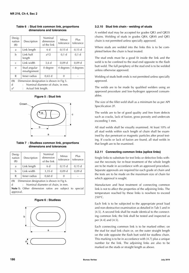
NR 216, Ch 4, Sec 2
Table 6 : Stud link common link, proportionsdimensions and tolerances
Figure 5 : Stud link
Table 7 : Studless common link, proportionsdimensions and tolerances
Figure 6 : Studless
3.2.10 Stud link chain - welding of studs
A welded stud may be accepted for grades QR3 and QR3Schains. Welding of studs in grades QR4, QR4S and QR5chain is not permitted unless specially approved.
Where studs are welded into the links this is to be com-pleted before the chain is heat treated.
The stud ends must be a good fit inside the link and theweld is to be confined to the stud end opposite to the flashbutt weld. The full periphery of the stud end is to be weldedunless otherwise approved.
Welding of studs both ends is not permitted unless speciallyapproved.
The welds are to be made by qualified welders using anapproved procedure and low-hydrogen approved consum-ables.
The size of the fillet weld shall as a minimum be as per APISpecification 2F.
The welds are to be of good quality and free from defectssuch as cracks, lack of fusion, gross porosity and undercutsexceeding 1 mm.
All stud welds shall be visually examined. At least 10% ofall stud welds within each length of chain shall be exam-ined by dye penetrant or magnetic particles after proof test-ing. If cracks or lack of fusion are found, all stud welds inthat length are to be examined.
3.2.11 Connecting common links (splice links)
Single links to substitute for test links or defective links with-out the necessity for re-heat treatment of the whole lengthare to be made in accordance with an approved procedure.Separate approvals are required for each grade of chain andthe tests are to be made on the maximum size of chain forwhich approval is sought.
Manufacture and heat treatment of connecting commonlink is not to affect the properties of the adjoining links. Thetemperature reached by these links is nowhere to exceed250°C.
Each link is to be subjected to the appropriate proof loadand non-destructive examination as detailed in Tab 5 and in[4.5]. A second link shall be made identical to the connect-ing common link; the link shall be tested and inspected asper [4.4] and [4.5].
Each connecting common link is to be marked either; onthe stud for stud link chain or, on the outer straight lengthon the side opposite the flash butt weld for studless chain.This marking is to be in accordance with [4.7] plus a uniquenumber for the link. The adjoining links are also to bemarked on the studs or straight length as above.
Desig-nation
(1)Description
Nominal dimension of the link
Minustolerance
Plustolerance
a Link length 6 d 0,15 d 0,15 d
b Link half length
a*/2 0,1 d 0,1 d
c Link width 3,6 d 0,09 d 0,09 d
e Stud angular misalignment
0 degree 4 degrees 4 degrees
R Inner radius 0,65 d 0 -
(1) Dimension designation is shown in Fig 5.d : Nominal diameter of chain, in mm.a* : Actual link length.
Desig-nation
(1)Description
Nominal dimensionof the link
Minustolerance
Plustolerance
a Link length 6 d 0,15 d 0,15 d
b Link width 3,35 d 0,09 d 0,09 d
R Inner radius 0,60 d 0 -
(1) Dimension designation is shown in Fig 6.d : Nominal diameter of chain, in mm.Note 1: Other dimension ratios are subject to specialapproval.
c
Crown
R
a
b
a
b
d
186 Bureau Veritas July 2019

NR 216, Ch 4, Sec 2
4 Testing and inspection of finished chain
4.1 General
4.1.1 This section applies to but not limited to finishedchain cable such as common stud and studless links, endlinks, enlarged end links and connecting common links(splice links).
All chain is to be subjected to proof load tests, sample breakload tests and sample mechanical tests after final heat treat-ment in the presence of a Surveyor. Where the manufac-turer has a procedure to record proof loads and theSurveyor is satisfied with the adequacy of the recording sys-tem, he need not witness all proof load tests. The Surveyoris to satisfy himself that the testing machines are calibratedand maintained in a satisfactory condition.
Prior to inspection the chain is to be free from scale, paintor other coating and is to have a suitably prepared surfaceas per applied NDE testing standard. The chain shall besand or shot blast to meet this requirement.
4.2 Proof and break load tests
4.2.1 The entire length of chain shall withstand the proofload specified in Tab 5 without fracture and shall not crackin the flash weld. The load applied shall not exceed theproof load by more than 10% when stretching the chain.Where plastic straining is used to set studs, the applied loadis not to be greater than that qualified in approval tests.
4.2.2 A break-test specimen consisting of at least 3 links isto be either taken from the chain or produced at the sametime and in the same manner as the chain. The test fre-quency is to be based on tests at sampling intervals accord-ing to Tab 8 provided that every cast is represented. Eachspecimen shall be capable of withstanding the break loadspecified without fracture and shall not crack in the flashweld. It shall be considered acceptable if the specimen isloaded to the specified value and maintained at that loadfor 30 seconds.
4.2.3 For chain diameters over 100 mm, alternative breaktest proposals to the above break test will be consideredwhereby a one link specimen is used. Alternatives are to beapproved by the Society, every heat is to be represented, thetest frequency is to be in accordance with Tab 8, and it is tobe demonstrated and proven that the alternative test rep-resents an equivalent load application to the three links test.
4.2.4 If the loading capacity of the testing machine is insuf-ficient, an alternative load testing machine is to be used thatdoes have sufficient capacity (e.g. two loading machines inparallel) provided the testing and calibration procedure areagreed with the Society.
Table 8 : Frequency of break and mechanical tests
4.3 Dimensions and dimensional tolerances
4.3.1 After proof load testing measurements are to be takenon at least 5 per cent of the links in accordance with[3.2.9].
4.3.2 The entire chain is to be checked for the length, fivelinks at a time. By the five link check the first five links shallbe measured. From the next set of five links, at least twolinks from the previous five links set shall be included. Thisprocedure is to be followed for the entire chain length. Themeasurements are to be taken preferably while the chain isloaded to 5-10% of the minimum proof load. The toler-ances for the 5 link measurements are indicated in Tab 5,any deviations from the 5 link tolerances are to be agreedby the client and the Society. The links held in the endblocks may be excluded from this measurement.
4.3.3 Chain dimensions are to be recorded and the infor-mation retained on file.
4.4 Mechanical tests
4.4.1 Links of samples detached from finished, heat treatedchain shall be sectioned for determination of mechanicalproperties. A test unit shall consist of one tensile and nineimpact specimens. The tensile specimen shall be taken inthe side opposite the flash weld. Three impact specimensshall be taken across the flash weld with the notch centeredin the middle. Three impact specimens shall be taken acrossthe unwelded side and three impact specimens shall betaken from the bend region.
4.4.2 The test frequency is to be based on tests at samplingintervals according to Tab 8 provided that every cast is repre-sented. Mechanical properties shall be as specified in Tab 3.
Nominal chain diameter (mm)
Maximum sampling interval (m)
Min - 48 91
49 - 60 110
61 - 73 131
74 - 85 152
86 - 98 175
99 - 111 198
112 - 124 222
125 - 137 250
138 - 149 274
150 - 162 297
163 - 175 322
176 - 186 346
187 - 198 370
199 - 210 395
211 - 222 420
July 2019 Bureau Veritas 187

NR 216, Ch 4, Sec 2
4.4.3 The frequency of impact testing in the bend may bereduced at the discretion of the Society provided it is veri-fied by statistical means that the required toughness is con-sistently achieved.
4.4.4 Hardness tests are to be carried out on finished chain.The frequency and locations are to be agreed by the Society.The recorded values are for information only and used as anadditional check to verify that the heat treatment processhas been stable during the chain production.
4.5 Non-destructive examination after proof load testing
4.5.1 All surfaces of every link shall be visually examined.Burrs, irregularities and rough edges shall be contourground. Links shall be free from mill defects, surface cracks,dents and cuts, especially in the vicinity where gripped byclamping dies during flash welding. Studs shall be securelyfastened. Chain is to be positioned in order to have goodaccess to all surfaces. In order to allow optimal access tothe surface area it is recommended that chain be hung inthe vertical position, however access to inspect the interlinkarea may only be possible with the chain in the horizontalposition.
4.5.2 Testing is to be performed in accordance with a rec-ognized standard and the procedures, together with accep-tance/rejection criteria are to be submitted to the Society forreview.
Manufacturer shall prepare written procedures for NDE.NDE personnel shall be qualified and certified according toISO 9712, ACCP or equivalent. Personnel qualification toan employer or responsible agency based qualificationscheme as SNT-TC-1A may be accepted if the employer’swritten practice is reviewed and found acceptable and theLevel III is ASNT Level III, ISO 9712 Level III or ACCP pro-fessional Level III and certified in the applicable method.NDE operators shall be qualified to at least level II.
4.5.3 Magnetic particles shall be employed to examine theflash welded area including the area gripped by the clamp-ing dies. Procedures are to be submitted to the Society forapproval. Procedures and equipment in accordance withthose approved shall be used.
Frequency of examination shall be every link. Additionally,10% of links are to be tested on all accessible surfaces.
Link surface at the flash weld shall be free from cracks, lackof fusion and gross porosity.
Testing shall be performed in accordance with ASTM E709or another recognized standard (e.g. ISO 9934) using wetcontinuous fluorescent magnetization technique. Non fluo-rescent techniques can be accepted in special cases wherethe standard inspection procedures are impractical.
Links shall be free from:
• relevant linear indications exceeding 1,6 mm in trans-verse direction
• relevant linear indications exceeding 3,2 mm in longitu-dinal direction
• relevant non-linear indications exceeding 4,8 mm.
4.5.4 Ultrasonics shall be employed to examine the flashweld fusion. Procedures are to be submitted to the Societyfor approval. Procedures and equipment in accordancewith those approved shall be used. On-site calibration stan-dards for chain configurations shall be approved.
Frequency of examination shall be every link.
The flash weld shall be free from defects causing ultrasonicback reflections equal to or greater than the calibrationstandard. The flash butt welds shall be ultrasonic tested (UT)in accordance with ASTM E587 or another recognized stan-dard using single probe, angle-beam shear waves in therange from 45 to 70°.
Single probe technique has limitations as far as testing ofthe central region is concerned and the flash weld imper-fections such as flat spots may have poor reflectivity. Whereit is deemed necessary, detectability of imperfections mayneed to be carried out by using a tandem technique, TOFDor phased array.
4.5.5 Stud welds, if used, shall be visually inspected. Thetoes of the fillets shall have a smooth transition to the linkwith no undercuts exceeding 1,0 mm. Additionally, at least10% of the stud welds distributed through the length shallbe dye penetrant tested according to ASTM E1417 or mag-netic particle tested according to ASTM E1444 or other rec-ognized standard.
Cracks, lack of fusion or gross porosity are not acceptable. Ifdefects are found, testing shall be extended to all stud weldsin that length.
4.6 Retest, rejection and repair criteria
4.6.1 If the length over 5 links is short, the chain may bestretched by loading above the proof test load specified pro-vided that the applied load is not greater than that approvedand that only random lengths of the chain need stretching.
If the length exceeds the specified tolerance, the overlengthchain links shall be cut out and [4.6.2] shall apply.
4.6.2 If single links are found to be defective or do not meetother applicable requirements, defective links may be cutout and a connecting common link inserted in their place.The individual heat treatment and inspection procedure ofconnecting common links is subject to the Society'sapproval.
Other methods for repair are subject to the written approvalof the Society and the end purchaser. Weld repair of chainis not permitted.
4.6.3 If a crack, cut or defect in the flash weld is found byvisual or magnetic particle examination, it shall be grounddown no more than 5% of the link diameter in depth andstreamlined to provide no sharp contours. The final dimen-sions must still conform to the agreed standard.
4.6.4 If indications of interior of flash weld defects in refer-ence to the accepted calibration standards are detectedduring ultrasonic examination, [4.6.2] shall apply.
188 Bureau Veritas July 2019

NR 216, Ch 4, Sec 2
4.6.5 If link diameter, length, width and stud alignment donot conform to the required dimensions, these shall becompared to the dimensions of 40 more links; 20 on eachside of the affected link. If a single particular dimension failsto meet the required dimensional tolerance in more than 2of the sample links, all links shall be examined and [4.6.2]shall apply.
4.6.6 If a break load test fails, a thorough examination withthe Surveyor informed in a timely manner is to be carriedout to identify the cause of failure. Two additional break testspecimens representing the same sampling length of chainare to be subjected to the break load test. Based upon satis-factory results of the additional tests and the results of thefailure investigation, it will be decided what lengths ofchain can be accepted. Failure of either or both additionaltests will result in rejection of the sampling length of chainrepresented and [4.6.2] shall apply.
4.6.7 If a link fails during proof load testing, a thoroughexamination with the Surveyor informed in a timely manneris to be carried out to identify the probable cause of failure ofthe proof test. In the event that two or more links in the proofloaded length fail, that section of proof loaded length is to berejected. The above failure investigation is to be carried outespecially with regard to the presence in other lengths of fac-tors or conditions thought to be causal to failure.
4.6.8 In addition to the above failure investigation, a breaktest specimen is to be taken from each side of the one failedlink, and subjected to the breaking test. Where multiplechains are produced simultaneously it is recognised that thepreceding flash butt welded link and subsequent flash buttwelded link will be on an alternative chain length or theother end of the chain length. In such cases the Society mayrequire that two additional break tests are to be taken fromthe lengths of chain that include the preceding and subse-quent welded links. Based upon satisfactory results of bothbreak tests and the results of the failure investigation, it willbe decided what length of chain can be considered foracceptance. Failure of either or both breaking tests willresult in rejection of the same proof loaded length.
Replacement of defective links is to be in accordance with[4.6.2].
If the investigation identifies defects in the flash butt weld ora lower strength flash weld “a glue-weld” is found, addi-tional NDE such as phased array UT is to be carried out toidentify if other links are affected. A full assessment of theflash butt welding machine is to be carried out, togetherwith assessment of the condition of the bar ends prior towelding.
4.6.9 Re-test requirements for tensile tests are given in Ch1, Sec 2, [2.3]. Failure to meet the specified requirements ofeither or both additional tests will result in rejection of thesampling length of chain represented and [4.6.2] shallapply.
4.6.10 Re-test requirements for Charpy V-notch impacttests are given in Ch 1, Sec 2, [4.4].
Failure to meet the requirements will result in rejection ofthe sampling length represented and [4.6.2] shall apply.
4.7 Marking
4.7.1 The chain shall be marked at the following places:
• at each end
• at intervals not exceeding 100 m
• on connecting common links
• on links next to shackles or connecting common links.
4.7.2 All marked links shall be stated on the certificate, andthe marking shall make it possible to recognize leading andtail end of the chain. In addition to the above requiredmarking, the first and last common link of each individualcharge used in the continuous length shall be traceable andadequately marked.
The marking shall be permanent and legible throughout theexpected lifetime of the chain.
4.7.3 The chain shall be marked on the studs as follows:
• chain grade
• certificate No.
• Society's stamp.
4.7.4 The Certificate number may be exchanged against anabbreviation or equivalent. If so, this shall be stated in thecertificate.
4.7.5 The chain certificate shall contain information onnumber and location of connecting common links. The cer-tificate number and replacement link number may beexchanged against an abbreviation or equivalent. If so, thisshall be stated in the certificate.
4.8 Documentation
4.8.1 A complete Chain Inspection and Testing Report inbooklet form shall be provided by the chain manufacturerfor each continuous chain length. This booklet shall includeall dimensional checks, test and inspection reports, NDTreports, process records, photographs as well as any non-conformity, corrective action and repair work.
4.8.2 Individual certificates are to be issued for each con-tinuous single length of chain.
4.8.3 All accompanying documents, appendices and reportsshall carry reference to the original certificate number.
4.8.4 The manufacturer will be responsible for storing, in asafe and retrievable manner, all documentation producedfor a period of at least 10 years.
July 2019 Bureau Veritas 189

NR 216, Ch 4, Sec 2
5 Testing and inspection of accessories
5.1 General
5.1.1 This section applies to but is not limited to mooringequipment accessories such as detachable connecting links(shackles), detachable connecting plates (triplates), endshackles, swivels and swivel shackles and subsea connec-tors.
5.1.2 All accessories are to be subjected to proof load tests,sample break load tests and sample mechanical tests afterfinal heat treatment in the presence of a Surveyor. Wherethe manufacturer has a procedure to record proof loads andthe Surveyor is satisfied with the adequacy of the recordingsystem, he needs not witness all proof load tests. The Sur-veyor is to satisfy himself that the testing machines are cali-brated and maintained in a satisfactory condition.
Prior to testing and inspection the chain accessories are tobe free from scale, paint or other coating.
5.1.3 For accessory production a Manufacturing ProcedureSpecification (MPS) is to be submitted to the Society thatdetails all critical aspects of accessory production, casting,forging, heat treating (including arrangement and spacing ofcomponents in the heat treatment furnaces), quenching,mechanical testing, proof and break loading and non-destructive examination.
5.2 Proof and break load tests
5.2.1 All accessories are to be subjected to the proof loadspecified for the corresponding stud link chain.
5.2.2 Chain accessories are to be tested at the break loadprescribed for the grade and size of chain for which they areintended. At least one accessory out of every batch or every25 accessories, whichever is less, is to be tested. For indi-vidually produced, individually heat treated, accessories oraccessories produced in small batches (less than 5), alterna-tive testing will be subject to special consideration. Alterna-tive testing is to be approved by the Society and thefollowing additional conditions may apply:
a) alternative testing is described in a written procedureand manufacturing procedure specification (MPS)
b) a finite element analysis is provided at the break loadand demonstrates that the accessory has a safety marginover and above the break load of the chain
c) strain age testing, as per approved procedure by theSociety, is carried out on the material grade produced tothe same parameters at the time of qualification
d) if an accessory is of a large size that will make heattreating in batches unfeasible or has a unique design,strain gauges are to be applied during the proof andbreak load tests during initial qualification and duringproduction. The strain gauge results from production areto be comparable with the results from qualification.
5.2.3 A batch is defined as accessories that originate fromthe same heat treatment charge and the same heat of steel.Refer to [2.3] and [2.4].
5.2.4 The accessories which have been subjected to thebreak load test are to be destroyed and not used as part ofan outfit, with the exceptions given in [5.2.5].
5.2.5 Where the accessories are of increased dimension oralternatively a material with higher strength characteristicsis used, they may be included in the outfit at the discretionof the Society, provided that:
a) the accessories are successfully tested at the prescribedbreaking load appropriate to the chain for which theyare intended, and
b) it is verified by procedure tests that such accessories areso designed that the breaking strength is not less than1,4 times the prescribed breaking load of the chain forwhich they are intended
c) strain age properties have been carried out on the mate-rial grade produced to the same parameters
d) strain gauges are to be applied during the break loadtest in the high stress locations to monitor that thestrains stay within allowable limits.
5.3 Dimensions and tolerances on dimensions
5.3.1 At least one accessory (of the same type, size andnominal strength) out of 25 is to be checked for dimensionsafter proof load testing. The manufacturer is to provide astatement indicating compliance with the purchaser'srequirements.
5.3.2 The following tolerances are applicable to accesso-ries:
a) nominal diameter: + 5 percent, -0 percent
b) other dimensions: ± 2½ percent
These tolerances do not apply to machined surfaces.
5.4 Mechanical tests
5.4.1 Accessories are to be subjected to mechanical testingas described in [2.3] and [2.4]. Mechanical tests are to betaken from proof loaded full size accessories that have beenheat treated with the production accessories they represent.
At least one accessory out of every batch or every 25 acces-sories, whichever is less, is to be tested.
Hardness tests are to be carried out on finished accessories.The frequency and locations are to be agreed by the Society.The recorded values are for information only and used as anadditional check to verify that the heat treatment processhas been stable during the accessory production.
The use of separate representative coupons is not permittedexcept as indicated in [5.4.5]below.
5.4.2 Test location of forged shackle bodies and forgedKenter shackles are to have a set of three impact tests and atensile test taken from the crown of the shackle. Tensile testson smaller diameter shackles can be taken from the straightpart of the shackle, where the geometry does not permit atensile specimen from the crown. The tensile properties andimpact values are to meet the requirements of Tab 3, withthe Charpy pieces on the outside radius.
190 Bureau Veritas July 2019

NR 216, Ch 4, Sec 2
5.4.3 The locations of mechanical tests of cast shackles andcast Kenter shackles can be taken from the straight part ofthe accessory. The tensile properties and impact values areto meet the requirements of Tab 3 in the locations specifiedin Fig 3.
5.4.4 The locations of mechanical tests of other accessorieswith complex geometries are to be agreed with the Society.
For non-circular sections, 1/4t (thickness) from the surface isconsidered appropriate.
Rolled plates are to be tested to the Standard to which theyare produced.
5.4.5 For individually produced, individually heat treated,accessories or accessories produced in small batches, (lessthan 5), alternative testing can be proposed to the Society.Each proposal for alternative testing is to be detailed in awritten procedure and submitted to the Society, and the fol-lowing additional conditions may apply:
a) if separately forged or cast coupons are used, they are tohave a cross-section and, for forged coupon, a reductionratio similar to that of the accessories represented, andare to be heat treated in the same furnace and quenchedin the same tank at the same time, as the actual forgingsor castings. Thermocouples are to be attached to thecoupon and to the accessories
b) if separately forged or cast coupons are agreed, it is tobe verified by procedure test that coupon properties arerepresentative of accessory properties.
5.4.6 A batch is defined as accessories that originate fromthe same heat treatment charge and the same heat of steel.refer to [2.3] and [2.4].
5.4.7 Mechanical tests of pins are to be taken as per Fig 3from the mid length of a sacrificial pin of the same diameteras the final pin. For oval pins, the diameter taken is to repre-sent the smaller dimension. Mechanical tests may be takenfrom an extended pin of the same diameter as the final pinthat incorporates a test prolongation and a heat treatmentbuffer prolongation, where equivalence with mid length testvalues have been established. The length of the buffer is tobe at least equal to 1 pin diameter dimension which isremoved after the heat treatment cycle is finished. The testcoupon can then be removed from the pin. The buffer andtest are to come from the same end of the pin as per Fig 7.
Figure 7 : Buffer and test piece location
5.5 Non-destructive examination after proof load testing
5.5.1 All chain accessories are to be subjected to a closevisual examination. Special attention is to be paid tomachined surfaces and high stress regions. Prior to inspec-tion, chain accessories are to have a suitably prepared sur-face as per the applied NDE testing standard. All non-machined surfaces are to be sand or shot blast to permit athorough examination. Where applicable, accessories shallbe dismantled for inspection of internal surfaces. All acces-sories are to be checked by magnetic particles or dye pene-trant technique.
5.5.2 Testing is to be performed in accordance with a rec-ognized standard, such as those indicated below, or othersrecognized standards:
a) magnetic particle testing (MT) of forgings:
• EN 10228-1, ASTM A275, using wet continuousmagnetization technique or equivalent standardssuch as ISO 4986, IACS Rec.69.
b) ultrasonic testing (UT) of forgings:
• EN 10228-3, ASTM A388, ISO 13588.
c) magnetic particle testing (MT) of castings:
• ASTM E709, using wet continuous magnetization-technique.
d) ultrasonic testing (UT) of castings:
• ASTM A609, ISO 13588.
The procedures, together with acceptance/rejection criteriaare to be submitted to the Society for review.
5.5.3 Manufacturer shall prepare written procedures forNDE. NDE personnel shall be qualified and certifiedaccording to ISO 9712, ACCP or equivalent. Personnelqualification to an employer or responsible agency basedqualification scheme as SNT-TC-1A may be accepted if theemployer’s written practice is reviewed and found accept-able and the Level III is ASNT Level III, ISO 9712 Level III orACCP professional Level III and certified in the applicablemethod. NDE operators shall be qualified to at least level II.
5.5.4 All surfaces shall be magnetic particle tested (MT).Testing shall be performed in accordance with standardsreferenced using the fluorescent technique. As a minimumsurfaces shall be free from:
• relevant linear indications exceeding 1,6 mm in trans-verse direction
• relevant linear indications exceeding 3,2 mm in longitu-dinal direction
• relevant non-linear indications exceeding 4,8 mm.
When required by the Society, ultrasonic testing is to be car-ried out on 100% of cast or forged accessories. The accep-tance/rejection criteria established for the design is to be met.
��� ���� ���
July 2019 Bureau Veritas 191

NR 216, Ch 4, Sec 2
5.5.5 The manufacturer is to provide a statement that nondestructive examination has been carried out with satisfac-tory results. This statement should include a brief referenceto the techniques and to the operator's qualification.
5.5.6 Weld repairs of finished accessories are not permit-ted.
5.6 Test failures
5.6.1 In the event of a failure of any test the entire batchrepresented is to be rejected unless the cause of failure hasbeen determined and it can be demonstrated to the Sur-veyor's satisfaction that the condition causing the failure isnot present in any of the remaining accessories.
5.7 Marking
5.7.1 Each accessory is to be marked as follows:
• Chain grade
• Society’s marks.
5.7.2 The certificate number may be exchanged against anabbreviation or equivalent. If so, this shall be stated in thecertificate.
5.8 Documentation
5.8.1 A complete Inspection and Testing Report in bookletform shall be provided by the manufacturer for each order.This booklet shall include all dimensional checks, test andinspection reports, NDT reports, process records and exam-ple photographs of components positioned in furnaces, aswell as any nonconformity, corrective action and repairwork.
5.8.2 Each type of accessory shall be covered by separatecertificates.
5.8.3 All accompanying documents, appendices and reportsshall carry reference to the original certificate number.
5.8.4 The manufacturer will be responsible for storing, in asafe and retrievable manner, all documentation producedfor a period of at least 10 years.
6 Chafing chain for single point mooring arrangements
6.1 Scope
6.1.1 These requirements apply to short lengths (approxi-mately 8 m) of 76 mm diameter chain to be connected tohawsers for the tethering of oil carriers to single point moor-ings, FPSO’s and similar uses.
6.2 Approval of manufacturing
6.2.1 The chafing chain is to be manufactured by worksapproved by the Society according to [1.3].
6.3 Materials
6.3.1 The materials used for the manufacture of the chafingchain are to satisfy the requirements of [2].
6.4 Design, manufacturing, testing and certification
6.4.1 The chafing chain is to be designed, manufactured,tested and certified in accordance with [3] [4] [5], exceptthat batch heat treatment is permitted.
6.4.2 The arrangement of the end connections is to be of anapproved type.
6.4.3 The common link is to be of the stud link type - gradeQR3 or QR4.
6.4.4 The chafing chain is to be capable of withstandingthe breaking test loads of 4884 kN (grade QR3) and6001 kN (grade QR4). See Note 1.
6.4.5 The chain lengths shall be proof load tested in accor-dance with [4.2]. The test load is 3242 kN for grade QR3and 4731 kN for grade QR4.Note 1: Documented evidence of satisfactory testing of similardiameter mooring chain in the prior 6 month period may be used inlieu of break testing subject to agreement with the Society.
Note 2: The requirements herein are also applicable to other diam-eter chafing chains, such as 84 mm and 96 mm, subject to compli-ance with the proof and break load requirements specified for thechain grade and diameters in [3.2.7] Tab 5.
192 Bureau Veritas July 2019

NR 216, Ch 4, Sec 3
SECTION 3 OTHERS
1 Side scuttles, windows and their glass panes
1.1 Scope
1.1.1 The requirements of this Article apply to fixed frames,window frames, dead covers and glass panes.The types of sidescuttles and windows which, in relation totheir position, are to be tested are indicated in the Society’sRules for the Classification of Steel Ships Pt B, Ch 8, Sec 10.
1.2 Manufacture
1.2.1 GeneralSidescuttles and windows which are subject to inspectionare to be manufactured in accordance with approved plansor standards and specifications recognised by the Society.
Manufacturing procedures are to be of appropriate type, tothe Surveyor’s satisfaction.
1.2.2 Frame materials Materials are to be of appropriate type and properties, asrequired in the approved plans or applicable standards.
They are to comply with the requirements of Chapter 2, inrelation to the type of material and the nature of the product.
Subject to approval for each case or application, the follow-ing types of material and products are generally regarded asappropriate:• hull steel plates, shapes and bars having Rm in the range
400-490 N/mm2
• steel forgings and castings• brass plates, shapes, bars and castings• light alloy castings and semi-finished products, of cate-
gory Al-Mg or Al-Mg-Si.
Subject to approval in individual cases, nodular cast iron oftype GS400 or GS370 may also be used.
1.2.3 Glass panesThe glass panes are to be of appropriate type and quality,manufactured in accordance with suitable procedures, tothe satisfaction of the Society, by recognised Manufacturers.
1.2.4 Quality of materialsThe product is to be free from detrimental defects.
1.3 Inspections and tests
1.3.1 Frame material tests Materials are to comply with the applicable requirementsand to be tested or certified accordingly; depending on theindividual cases, they are also to be submitted to the follow-ing additional tests:
a) a bend test, as indicated below, depending on the typeof material:
• brass products: d ≤ 1 s α ≥ 60°
• light alloy products: d ≤ 3 s α ≥ 60°
• cast iron: d ≤ 4 s α ≥ 60°
where:
s : Thickness of the specimen (which, as far aspossible, should be equal to the thickness ofthe product)
d : Diameter of the mandrel
α : Required bend angle, which is to beattained without cracks or other defects.
b) for castings, as an alternative to the bend test performedon specimens, it may be agreed to perform a bend testdirectly on a completed piece. Such test may also berequired by the Surveyor as an additional randomcheck. When this test is performed as an alternative tothat on specimens, the number of pieces tested is to beone for every batch of not more than 50 equal pieces(25 in the case of cast iron products) originating fromthe same heat.
These tests are to be performed on a mandrel having adiameter equal to twice the thickness of the piece (but notless than 50 mm in the case of cast iron products); therequired bend angles which are to be attained withoutcracks or other defects depending upon the material and thefinished product are as follows:
• steel castings:
fixed frames, window frames and dead covers: α ≥ 20°
• brass castings:
fixed frames and window frames: α ≥ 10°
dead covers: α ≥ 15°
• light alloy castings:
fixed frames and window frames: α ≥ 6°
dead covers: α ≥ 15°
• malleable or nodular cast iron: α ≥ 15°.
1.3.2 Glass panes
Glass panes are to be in toughened safety glass in accor-dance with ISO 21005 standard. The acceptance of ordi-nary glass is subject to special approval by the Society ineach case.
The glass Manufacturer is to certify the homogeneity of thebatches submitted for tests, as regards material, manufactur-ing procedure, heat treatment and suitability to meet thespecified test requirements.
July 2019 Bureau Veritas 193

NR 216, Ch 4, Sec 3
Glass panes are to be tested as specified in the followingitems a) or b).
a) a hydrostatic test of one glass pane for each batch of100 (or fraction of 100) glass panes equal in shape anddimensions and manufactured with continuity andusing the same procedure and treatments; the pane is tobe tested with a load uniformly distributed on the netarea, at the test pressures indicated in Tab 1, in relationto the diameter and thickness of the pane.
The test pressure is to be applied for at least one minute;the glass pane is not to break.
In the case of glass panes having shape other than circu-lar, the test is to be performed on a disk obtained from aglass pane for each batch homogeneous as regardsdimensions, manufacturing procedure and heat treat-ment and with a total surface of 25m2 or fractionthereof. The disk, for the test and possible re-tests, is tobe taken before the tempering process and treated withthe glass panes of the batch which it represents.
If a test produces unsatisfactory results, the test is to berepeated in duplicate on two new glass panes from thesame batch; for the acceptance of the batch, both newtests are to be satisfactory; in the case of tempered glasspanes of non-circular shape, in order not to have toreject the batch in the case of unsatisfactory test results,it is recommended that two additional disks should betaken for possible re-testing from the batch before thetempering treatment.
b) a punch test in accordance with ISO 614 as an alterna-tive to the hydrostatic test mentioned in a).
This test method is applicable both to non-opening andopening sidescuttles and rectangular windows; whentested, the glass edges are to be not less than 25mmfrom the inner edge of the rubber ring (see Fig 1).
The test consists of applying to the glass pane, which issupported by a steel plate with a circular hole, therequired load through a rounded steel shaft acting alongthe centre of the hole.
The test is to be performed on 4 glass panes for eachbatch homogeneous as specified in a).
In the case of batches of 4 glass panes or less, the test isto be performed on each glass pane.
In the case of matt glass panes obtained by a specialtreatment of one of the surfaces of a transparent glasspane, the test is to be performed after the treatment andthe load is to be applied to the surface which has notbeen treated.
The required test loads are indicated in Tab 2, in relationto the thickness of the glass pane and the diameter ofthe hole in the support plate.
The test is to be performed using the equipment and theprocedure specified in ISO 614 Standard (see Fig 1).
Figure 1 : Testing apparatus for punch testingtoughened glass panes
Note 1: Testing equipment
The equipment can be used for glass panes of sidescuttles havingnominal diameter 200, 250 mm or greater and for glass of rectan-gular windows of any size.
The base of the testing equipment is formed by:
• a steel platform with upper flat surface provided with a 200mm central hole with rounded edges (1);
• a rubber ring (2), having hardness in the range from 40 to 60IRHD (International Rubber Hardness Degrees), with an insidediameter of 200 mm, thickness of 2 mm and width of at least15 mm, located around the hole, between the steel plate andthe glass pane, so as to compensate for any slight irregularitiesof the platform and to prevent the edges of the platform frombearing directly against the glass pane;
• a suitable adapter provided with a hole of 150 mm (6) withrounded edges, to be used when testing glass panes have adiameter of 200 mm (in these cases, a rubber ring (2) having aninside diameter of 150 mm is to be interposed between theupper surface of the adapter and the glass pane).
The glass pane to be tested (3) is positioned over the hole in theplatform and a shaft (4) with a diameter of 50 mm and a fullyrounded end is arranged above the glass pane along the axis of thehole.
A felt disk (5) having a thickness of 5mm is arranged between theshaft and the glass pane, for the purpose of distributing the load.
Note 2: Testing procedure
The applied load is to be increased at a rate of 1000 N per secondup to the test load specified in Tab 2. The test load is to be main-tained for a period of at least 5 seconds and is then to be removedgradually.
The glass panes are to withstand the required test load without frac-ture.
4
5
3
2
1
3
2
6
1
O 150
O 200
O 50
r=25
194 Bureau Veritas July 2019

NR 216, Ch 4, Sec 3
Table 1 : Hydrostatic test pressurefor glass panes of sidescuttles and windows
Table 2 : Punch test load
1.3.3 Visual and dimensional examination
The following examinations are to be performed:
a) visual examination
b) dimensional and conformity checks to be performed bythe Manufacturer, with checks at the discretion of theSurveyor.
1.4 Identification and marking
1.4.1 All glass panes tested with satisfactory results are tobe marked by the Manufacturer in a suitable position whichremains clearly visible after the glass pane has beeninstalled, as follows:
• trade mark and/or name of the Manufacturer
• Society’s brand
• nominal thickness, in mm.
In the case of glass panes tested with the punch test, thespecial marking mentioned in ISO 614 is to be used as fol-lows:
• transparent glass panes: single line triangle
• matt glass panes: double line triangle.
The nominal thickness of the glass pane, in mm, is to bemarked inside the above triangles.
The markings identifying the origin of the glass pane are tobe specified to the Society when the individual Manufactur-ers are recognised.
2 Pressure bottles
2.1 Scope
2.1.1 GeneralThe requirements of this Article apply to seamless pressurebottles in carbon, carbon manganese and alloy steels, andto welded bottles in carbon and carbon manganese steels.
Seamless bottles are mainly used for carbon dioxide sys-tems and welded bottles for portable fire extinguishers.
Steel grades to be used for the manufacture are to complywith those specified in Chapter 2 as applicable or with rec-ognised standards.
The steel is to be killed and for certain applications, forexample low temperature applications, fine grained steel isto be used.
2.1.2 Mass productionIn the case of small bottles mass produced by Manufactureswho have been approved by the Society for this purpose,alternative testing procedures to those indicated in [2.3.1]may be accepted.
2.1.3 Materials other than steelThe requirements relevant to bottles in material other thansteel are to be considered on a case-by-case basis, with cri-teria and procedures as similar as possible to those speci-fied in this Article.
2.2 Manufacture
2.2.1 Bottles are to be manufactured according toapproved plans.The manufacturing process of seamless bottles is to beapproved for the individual Manufacturers.
The approval of the manufacturing process is also requiredfor welded bottles intended for portable fire extinguishershaving thickness of the cylindrical shell less than 3 mm.
The materials used in the bottle manufacture are to betested or provided with a Manufacturer’s certificate of con-formity.
2.3 Inspection and tests
2.3.1 General The following inspections and tests are to be performed:
a) sectioning of one bottle from each batch formed of200 pieces or fraction thereof, homogeneous as regardsdimensions, manufacturing process and heat treatmentfor the execution of:• thickness measurements of the shell on three trans-
verse sections in way of neck, middle and bottomend
• 1 tensile test on longitudinal test specimen, 2 bend-ing tests to be performed along the curvature and,for thicknesses ≥ 5 mm, 3 Charpy V-notch impacttests on longitudinal specimens, to be performed at−20°C. For low temperature applications, the testtemperature is to be specified in the individualcases.
Thickness of glass
pane (mm)
Pressure (N/mm2)for a glass pane net diameter (mm) of:
200 250 300 350 400 450
6 0,33 0,21 − − − −
8 0,58 0,37 0,26 0,19 − −
10 0,92 0,58 0,41 0,30 0,23 0,18
12 1,32 0,84 0,59 0,43 0,33 0,26
15 − 1,32 0,92 0,67 0,51 0,41
19 − − 1,47 1,08 0,83 0,65
Thickness of glass pane (mm)
(tolerance: 0 +2)
Test loads (N) for ahole diameter in support plate of:
200 mm 150 mm
6 3400 3500
8 6500 6700
10 10200 11000
12 15500 16500
15 24000 25500
19 33400 36800
July 2019 Bureau Veritas 195

NR 216, Ch 4, Sec 3
b) hardness tests to be performed on bottles of quenchedand tempered steel and, at the discretion of the Sur-veyor, also in other cases
c) external and internal visual examination (direct exam-ination or, in the case of insufficient size of openings,examination by auxiliary means), dimensional check,determination of tare and capacity (such examinationsare to be performed by the Manufacturer with checks atthe Surveyor’s discretion)
d) hydrostatic test on each bottle; test pressure as requiredby the relevant Rules or by the particular requirementsapplicable in the individual cases
e) non-destructive checks as indicated on the plans at thetime of the approval of the manufacturing process
f) for welded bottles, additional tests on welded joints asspecified at the time of the approval of the manufactur-ing process or indicated on the approved plans.
2.3.2 Tensile test
In the tensile test, the values of the yield strength ReH andRp0,2 , the tensile strength Rm and the elongation A (%) are tocomply with the values specified for the correspondingsteel.
The value of A (%) min, for thicknesses equal to or greaterthan 3 mm, is to be not less than the value calculated withthe following formula, and in no case less than 14%:
where Rm is the value, in N/mm2, of the tensile strengthdetermined by the tensile test.
This requirement for A (%) min may be reduced by 15% forthicknesses less than 3 mm down to 2 mm, and by 30% forthicknesses less than 2 mm.
2.3.3 Bend test
In the bending test, the angle to which the specimen is to bebent without showing defects is 180°; a mandrel having adiameter not exceeding “n” times the thickness of the spec-imen, depending on the minimum specified tensile strengthRm for the steel, as specified in Tab 3, is to be used.
Table 3 : Coefficient n for determination ofthe maximum allowed mandrel diameter in bend test
2.3.4 Impact test
In the Charpy V-notch impact test, the value of the absorbedenergy, determined as an average of three tests, is to be notless than the value indicated in Tab 4 depending on theminimum tensile strength of the steel.
Table 4 : Impact test - requirements
2.4 Identification, marking and certification
2.4.1 The Manufacturer is to adopt a system of identifica-tion which will enable all finished bottles to be traced to theoriginal materials and their manufacturing.
All bottles which have been tested and inspected with satis-factory results are to be marked with the following details:
a) Manufacturer’s name or trade mark
b) Society’s brand
c) place and date of testing
d) production number or other marking enabling the trace-ability
e) test pressure
f) additional optional marks such as file number and codeof the local inspection office, Surveyor’s personal stamp.
Special marking and certification procedures may be agreedupon for supplies by Manufacturers granted the use of analternative testing procedure.
2.4.2 The testing documentation indicated in Ch 1, Sec 1,[4.2.1] is required and is to include all the information, asappropriate.
The testing or works’ certificate of the material used is to beenclosed with the testing documentation.
Where applicable, the reports relevant to the non-destruc-tive examination, pressure test and heat treatment are to beenclosed with the testing documentation.
2.4.3 Before signing the Society’s inspection certificate, theSurveyor is to be provided by the Manufacturer with a writ-ten declaration stating that the bottles have been manufac-tured by a process approved by the Society, they complywith the applicable requirements and they have been satis-factorily tested in accordance with the Society’s Rules.
Rm (N/mm2) n
≤ 430 2
431 - 510 3
511 - 590 4
591 - 690 5
691 - 790 6
791 - 890 7
> 890 8
A 25000 224, R⋅ m
--------------------------≥
Steel typesTensile strength (N/mm2)
Average impact energy at −20°C min. KV (J/cm2)
Carbon andcarbon- manganese
≤ 510 34
Alloy steels quenchedand tempered
> 510 49
196 Bureau Veritas July 2019

NR 216
Chapter 5
WELDING
SECTION 1 GENERAL REQUIREMENTS
SECTION 2 APPROVAL OF WELDING CONSUMABLES
SECTION 3 APPROVAL OF OVER WELDABLE SHOP PRIMERS
SECTION 4 APPROVAL OF WELDING PROCEDURES
SECTION 5 APPROVAL OF CO2 LASER WELDING PROCEDURES
July 2019 Bureau Veritas 197

198 Bureau Veritas July 2019

NR 216, Ch 5, Sec 1
July 2019 Bureau Veritas 199
SECTION 1 GENERAL REQUIREMENTS
1 Scope
1.1 General
1.1.1 This Section specifies the general requirements forfabrication by welding, and the other Sections of the Chap-ter concern the requirements for approval of welding con-sumables ( Sec 2), over weldable shop primers ( Sec 3) andwelding procedures ( Sec 4 and Sec 5).
1.1.2 The requirements are essentially intended for thewelding of weldable steels and aluminium alloy grades cov-ered by the applicable Articles of these Rules.
1.1.3 Different materials, applications and procedures, aswell as other standards and specifications, may be consid-ered by the Society on a case-by-case basis.
2 Fabrication by welding
2.1 General
2.1.1 Fabrication by welding is to be carried out in compli-ance with the applicable Society Rules and according tonormal good practice, general or specific to the individualprocesses, to the Surveyor’s satisfaction; in particular theconditions stated at the time of approval and authorisationfor the use of individual processes are to be complied with.
The welded structures, the relevant details and the size ofwelds are to comply with the applicable requirements; anyother requirements indicated on the approved plans orspecified during survey of construction are also to be com-plied with.
2.2 Approval
2.2.1 Plans
The constructional plans are to be submitted for approvalwhen required by the Rules or in individual cases and are tocontain the necessary data relevant to the fabrication bywelding of the structures and items represented. In particu-lar, material types, welding details, welding processes andweld size are to be indicated; any details not represented inthe plans are, in any case, to comply with the applicablerequirements.
2.2.2 Welding procedures and consumables
Welding to be used in hull construction, machinery, pres-sure systems and equipment subject to the inspection of theSociety, is to be carried out with approved welding consum-ables and in accordance with approved welding proce-dures.
Requirements regarding the use of the various grades ofapproved consumables are indicated in the parts of theRules concerning the application or at the time of planapproval.
2.2.3 Welders and welding operators
Welders for manual welding and for semiautomatic weldingprocesses are to be properly trained and are to be certifiedby the Society, as required in the individual applications,unless otherwise agreed.
Welders are to be certified according to the proceduresgiven in Rule Note NR476 Approval Testing of Welders.
The certification is to be in due course of validity.
Personnel manning the automatic welding machines are tobe competent and sufficiently trained.
2.2.4 Welding supervision
Welders are to be supervised and assisted, in the course ofthe welding operation, by an adequate number of compe-tent supervisors, such as to ensure efficient control of thewelding production.
Certification of the welding inspectors is not compulsoryand is left to the discretion of the Manufacturer, except inparticular cases where it may be required by the Society.
2.2.5 NDT operators
Non-destructive tests are to be carried out by qualified per-sonnel certified or by recognised bodies in compliance withappropriate standards.
The qualifications are to be appropriate to the particularapplication.
2.3 Type of joints, edge preparations and size
2.3.1 General
The types of joints and the edge preparations are to beappropriate to the welding processes adopted, to the partic-ular structures and to the stresses to which they are sub-jected, to the satisfaction of the Society.
Size and design are to be in accordance with requirementsgiven in the Rules relevant to the applications, approvedplans, and specific provisions stipulated for hulls and forpressure systems and machinery.
2.4 Welding execution and control
2.4.1 Edge preparation, surface conditions, assembly pre-and post- weld heating, welding sequences and inspectionsof the welded structures are to be in accordance with goodpractice and, where applicable, are to comply with therequirements given in the Rules relevant to the applications.

NR 216, Ch 5, Sec 2
SECTION 2 APPROVAL OF WELDING CONSUMABLES
1 General
1.1 Scope
1.1.1 The requirements of this Section apply to theapproval and periodical control tests of consumables forwelding carbon and carbon manganese steels, high strengthquenched and tempered steels, chromium and chromium-molybdenum steels, nickel steels for low temperature appli-cations, austenitic and austenitic-ferritic stainless steels, andaluminium alloys.
This Article specifies the requirements common to all theabove-mentioned welding consumables, while the appro-priate specific requirements are indicated in Articles [2] to[15].
The following categories of welding consumables are con-sidered:
• covered electrodes for manual and gravity welding
• wire/flux combinations for submerged arc welding
• solid wire/gas combinations for continuous wire arcwelding
• flux cored wires for continuous wire arc welding with orwithout shielding gas
• consumables for electrogas and electroslag welding.
1.2 Grading and designation
1.2.1 GeneralConsumables are classified depending on the mechanicaland chemical properties of the filler metal; different gradesor type of consumables may be considered for specificapplications or materials on a case-by-case basis.
1.2.2 Consumables for C and C-Mn steels and for Q-T steels
Welding consumables intended for welding C and C-Mnsteels are divided into groups related to the strength level(minimum specified yield strength) of the steel; each groupis subdivided into grades depending on the impact test tem-peratures, as indicated in Tab 1.
1.2.3 Consumables for Mo and Cr-Mo steels
Consumables intended for welding Mo and Cr-Mo steels aredesignated by a symbol indicating the nominal Mo and Crpercentage content of the deposited weld metal, as follows:
a) M for Mo = 0,5
b) C1M for Cr = 1,25 and Mo = 0,5
c) C2M1 for Cr = 2,25 and Mo = 1
1.2.4 Consumables for Ni steels for low temperature applications
Consumables intended for welding nickel steels are desig-nated by a symbol indicating the type of nickel steel forwhich the consumables are intended, as follows:
a) N15 for steels with Ni = 1,30 - 1,70(%)
b) N35 for steels with Ni = 3,25 - 3,75 (%)
c) N50 for steels with Ni = 4,75 - 5,25 (%)
d) N90 for steels with Ni = 8,50 - 10,0 (%)
Table 1 : Consumable grades for C-Mn steels
Steelstrength level
Consumable grades based on impact test temperature at (°C)
+ 20 0 − 20 − 40 − 60
Normal strength 1 2 3 4 −
Higher strength (1)
• ≥ 315, < 360 N/mm2
• ≥ 360, < 400 N/mm2
1Y (2) 2Y2Y40
3Y3Y40
4Y4Y40
5Y5Y40
Extra high strength (1) 3Y42, 3Y46, 3Y50, 3Y55, 3Y62, 3Y69,
3Y89, 3Y96
4Y42, 4Y46, 4Y50, 4Y55, 4Y62, 4Y69
4Y89, 4Y96
5Y42, 5Y46, 5Y50, 5Y55, 5Y62, 5Y69
(1) The symbol Y, which indicates the high strength groups is followed, for steels having the minimum specified yield strengthequal to, or higher than, 355 N/mm2, by a number related to the minimum specified yield strength value of the weld metal (e.g.42 for a minimum yield strength of 420 N/mm2).
(2) Grade not applicable to covered electrodes.
200 Bureau Veritas July 2019

NR 216, Ch 5, Sec 2
1.2.5 Consumables for austenitic and austenitic-ferritic (duplex) stainless steels
Consumables intended for welding austenitic steels are des-ignated by a symbol corresponding to the AWS designationof the weld deposit, as follows: 308, 308L, 316, 316L,316LN, 317, 317L, 309L, 309, 309Mo, 310, 310Mo, 347.
Consumables intended for welding austenitic-ferritic steelsare designated by a symbol indicating the nominal percent-age content of Cr and Ni in the deposited metal (e.g. 2205means 22% Cr and 5% Ni).
1.2.6 Consumables for aluminium alloys
Consumables intended for welding aluminium alloys aredesignated by the initial letter R or W for rod or wire prod-ucts, respectively, and by the letters A, B, C, D dependingon the alloy type and strength level used for the approvaltests.
1.2.7 Additional symbols
Further symbols may be added, as appropriate, as a prefixor suffix to the grade as indicated in the following:
a) prefix S or SA for semiautomatic welding process
b) prefix A for automatic welding process
c) prefix AV for electrogas or electroslag welding process
d) suffix T, M, TM, U for automatic process with two run(T), multi-run (M), both (TM) or one-side (U) weldingtechniques
e) suffix H or H15, HH or H10, HHH or H5 for controlledhydrogen content of weld metal as per Tab 8
f) suffix D when mechanical properties on weld metalhave also been verified in the stress relieved condition.
1.3 Approval procedure
1.3.1 Request for approval
The request for approval is to be submitted to the Society bythe Manufacturer, together with the specific information indi-cated in the Articles relevant to the various consumables.
1.3.2 Quality of manufacturing
The Manufacturer’s plant, method of production and qualitycontrol of welding consumables are to be such as to ensurereasonable uniformity in manufacture.
The Manufacturer is to ascertain this uniformity by means ofanalysis and systematic testing on each production batch.
In general, the consumables are to maintain the specifiedcharacteristics for a period of time of at least six monthsafter the date of delivery, when properly stored in a dryatmosphere and kept in the original packaging.
The consumables are to be supplied so packaged as toensure compliance with the above requirement; the pack-aging is to be sufficiently strong to resist the usual transpor-tation and handling operations.
The Manufacturer is to stamp on each container or bag, asapplicable, the markings which are necessary to trace backeach production.
1.3.3 Approval tests
The welding consumables are approved subject to a satis-factory inspection of the Manufacturer’s works by the Sur-veyor and to satisfactory results of approval tests.
The approval tests required are to be performed on samplesof consumables representative of the production.
Sampling procedures are to be agreed with the Surveyor.
In general, the approval tests consist of the followingchecks:
a) check of the mechanical properties of the depositedmetal and welded joints and of the chemical composi-tion of the deposited metal
b) check of the hydrogen contents, where required
c) check, at the request of the interested parties, of free-dom from hot cracks, under specific test conditions.
Welding and inspection of the test samples and mechanicaltests are to be carried out in the presence of the Surveyor.
The tests are to be carried out in laboratories and test roomsrecognised by the Society.
Unless otherwise specified, test specimens and proceduresare to be in accordance with the applicable Society require-ments or standards recognised by the Society.
1.3.4 Certification
Upon satisfactory completion of the approval tests, a certifi-cate of approval, stating the grade under which the consum-able has been approved and the terms of validity of theapproval, is issued by the Society to the Manufacturer.
The approved welding consumables and relevant grades areentered in the special lists of consumables approved by theSociety.
1.3.5 Annual inspections and tests
The workshops where approved materials are manufacturedare subject to annual inspections by the Surveyor.
During the inspection, samples of the approved consum-ables are selected by the Surveyor and subjected to the testsdetailed in the Articles relevant to the various products.These tests are to be repeated annually so as to provide anaverage of at least one test per year.
At the Society’s discretion, the consumables to be used inthe above tests may be obtained, instead of from the Manu-facturer as stated above, from users or dealers; the consum-ables are to be recently produced (in general less than 6months).
Alternative procedures based on quality control and qualityassurance systems may be considered and accepted subjectto special approval by the Society, which will state the rele-vant acceptance conditions on a case-by-case basis.
July 2019 Bureau Veritas 201

NR 216, Ch 5, Sec 2
1.3.6 Manufacturer’s responsibilities
After the approval has been obtained, and irrespective ofthe periodical tests carried out by the Society, the Manufac-turer is fully responsible for the quality of the finished prod-uct and compliance with the specified requirements, asverified in the approval and periodical control tests.
The Manufacturer is to keep up-to-date records of the man-ufacture of the approved consumables, including details ofthe history of the single productions and results of associ-ated tests. The Society is to have free access to these recordsat all times.
The Manufacturer is responsible for reporting to the Societyany major modifications introduced in the production pro-cedure subsequent to its approval.
Full compliance on the part of the Manufacturer with all therequirements stated by the Society in connection with theapproval of consumables is an essential condition for grant-ing and renewing such approval.
1.3.7 Firms with several workshops or dealers
When consumables of the same brand are manufactured indifferent workshops belonging to the same Manufacturer,the complete series of tests is generally performed in oneworkshop only. In the other workshops, a reduced test pro-gram, at least equivalent to annual tests, is permitted if theManufacturer certifies that the material used and the fabri-cation process are identical to those used in the mainworks.
1.3.8 Different brand names
When a consumable already approved at a manufacturer istransferred for sale under a different brand name to themanufacturer or to a dealer, the manufacturer and thedealer where applicable have to certify that the consumablewith the alternative brand name is strictly identical to theconsumable already approved.
1.3.9 Changes in grading
Changes in grading of welding consumables are to be con-sidered only at the Manufacturer’s request, in general at thetime of annual testing. For upgrading, tests from butt weldassemblies are generally required as a minimum in additionto normal annual tests, as specified here below.
For upgrading referring to impact properties, Charpy V-notch impact tests are to be performed at the upgrade tem-perature on the respective butt weld assemblies required forapproval.
For upgrading referring to higher strength steels, all buttweld tests required for the approval are to be effected usinghigher strength steel as parent metal.
For upgrading referring to hydrogen content, tests accordingto [2.4] are to be carried out as appropriate.
Downgrading or withdrawal of the approval occurs whenthe prescribed tests and re-tests fail to meet the require-ments.
1.3.10 Additional tests
The Society may, in some specific cases, request additionaltests or requirements as deemed necessary.
1.4 Preparation and welding of test assem-blies
1.4.1 Base material
The base material used for the test assemblies is to be of thesteel grade appropriate to the consumable grade as speci-fied in the various Articles.
For the preparation of all weld metal test assemblies, anygrade of structural steel may be used. When the chemicalcomposition of welded metal is substantially different fromthe base material, an overlay of side walls and backing stripmay be carried out, as deemed necessary.
For the preparation of butt welded assemblies, steel gradesare to be chosen depending on the grade of consumables.
When a welded joint is performed, the edges of the platesare to be bevelled either by mechanical machining or byoxygen cutting; in the latter case, a descaling of the bev-elled edges is necessary.
1.4.2 Welding conditions and type of current
Welding conditions used, such as amperage, voltage, travelspeed etc., are to be within the range recommended by theManufacturer for normal good welding practice.
Where it is stated that a filler metal is suitable for both alter-nating current (a.c.) and direct current (d.c.), alternatingcurrent is to be used for welding the test assemblies formechanical tests. When samples for checking the operatingcharacteristics are required, both types of current are gener-ally to be used. When samples for hot cracking tests arerequired, direct current is to be used.
Direct current is identified in the approval documentationwith the symbols:
• CC+ or DCEP for positive electrode
• CC− or DCEN for negative electrode.
1.4.3 Post-weld heat treatment
Post-weld heat treatment of the welded assemblies is notallowed where the consumables are to be approved for theas welded condition only.
1.5 Mechanical tests
1.5.1 General
The test specimens for mechanical tests are to be taken fromthe welded assemblies as indicated in the various Articles;specimen preparation and test results are to comply withthe requirements from [1.5.2] to [1.5.6].
The requirements relevant to the calibration of the equip-ment, preparation of test specimens and testing procedure,detailed in Ch 1, Sec 2, are also to be complied with, asappropriate.
202 Bureau Veritas July 2019

NR 216, Ch 5, Sec 2
1.5.2 Tensile tests
Round test specimens for longitudinal tensile tests and flattest specimens for transverse tensile tests are to be taken asdescribed below:
a) round specimen:
The longitudinal axis is to coincide with the centre of theweld and mid-thickness of the weld in the all weld metalassemblies and second run in the two run welded assem-blies. The specimen is to be in accordance with Ch 1, Sec2, [2.1.10]; the specimen may be heated to a temperaturenot exceeding 250°C for a period not exceeding 16 hours,for hydrogen removal prior to testing.
The yield stress, tensile strength and elongation are to bedetermined and are to comply with the requirementsspecified for the various consumables; the reduction ofarea is to be determined and reported for information.
b) flat tensile specimen:
The test specimen is to be in accordance with Ch 1, Sec2, [2.1.11].
The tensile strength is to be determined together withthe fracture position and is to comply with the require-ments specified for the various consumables.
1.5.3 Transverse bend tests
Face and root bend test specimens having 30 mm width andfull plate thickness are to be machined transverse to thewelded joint. The upper and lower surfaces of the weld areto be filed, ground or machined flush with the surface of theplate and the corners in tension rounded to a radius notexceeding 2 mm.
Two bend specimens are required; one specimen is to betested with the face of the weld in tension and the otherwith the root of the weld in tension.
If the plate thickness exceeds 25 mm, it may be reduced tothis size by machining on the compression side of the testspecimen.
Alternatively, two side bend specimens may be taken in lieuof root and face bend specimens; side bend specimens mayalso be required in addition to or in lieu of root and facebend specimens for specific applications [1.5.4].
Bend test specimens are to be bent without fracture orcracks through an angle of 120°, unless a different angle isspecified over a former having diameter as indicated in thevarious Articles; however superficial cracks or open defectsnot exceeding 3 mm may be disregarded.
1.5.4 Side bend tests
Side bend test specimens, having full plate thickness andwidth 10 mm, are generally required in addition to the rootand face bend tests for the approval of wire/gas combina-tions, and are required in lieu of the root and face bend testsfor electrogas or electroslag assemblies.
1.5.5 Longitudinal bend tests
When longitudinal face or root bend tests are required, testspecimens in accordance with an appropriate standard areaccepted.
1.5.6 Impact tests
Charpy V-notch impact specimens are to be cut with theirlongitudinal axis transverse to the weld joint and positionedas follows:
a) for deposited metal and butt weld test assemblies withmulti-run technique: at mid-thickness of the weld
b) for two run welded test assemblies: on the second runside, 2mm below the surface
c) for electroslag and electrogas welded test assemblies:2 mm below the surface
d) for one side automatic welding processes: 2 mm belowthe face side and 2 mm below the root side of the testassemblies; for thicknesses ≥ 30 mm, specimens at mid-thickness are also to be taken.
The notch is to be cut in the face of the specimen perpen-dicular to the surface of the plate and to be positioned inthe centre of the weld. For electrogas and electroslag weld-ing, an additional set with the notch at 2 mm from thefusion line in the weld metal is to be taken.
A set of three specimens is to be prepared and tested. Theaverage impact energy is to comply with the values speci-fied for the various consumables and only one individualvalue may be lower than the average required, provided it isnot lower than 70% of it.
1.6 Test samples for checking the chemical composition of deposited weld metal
1.6.1 For some products (see [12], [13], [14]), the chemicalcomposition of weld metal deposited with electrodes isrequired to be verified on samples welded for this purpose.
1.6.2 The test samples consist of a test plate of the speci-fied steel having minimum sides 80 x 80 mm2 and 15 mmthickness.
On the above test plate, whose surface is to be cleaned bygrinding to remove any trace of oxide, grease and paint, aweld pad is deposited in layers by welding in the flat posi-tion, each layer being formed by flanked beads. The mini-mum dimensions of the pad are to be as indicated in Tab 2.
The width of each bead of each layer is to be 1,5 to 2,5times the diameter of the electrode. It is recommended thateach layer should be deposited in a direction perpendicularto the previous one.
The current adopted for welding the test samples is to bewithin the range recommended by the Manufacturer; in thecase of electrodes for use both with a.c. and d.c. current,the welding is to be carried out with alternating current.
After each layer has been deposited, the pad may be cooledto room temperature by immersion in water for 30 seconds.
The surface of each layer is to be free from slag inclusionsand blow holes.
July 2019 Bureau Veritas 203

NR 216, Ch 5, Sec 2
Table 2 : Pad dimensions
1.6.3 After the welding is completed, the top surface of thepad is to be removed by mechanical means and discarded.
Shavings sufficient for checking the chemical compositionare then to be taken in such a manner that no metal isremoved closer to the surface of the base plate than the dis-tance indicated in Tab 3.
The use of lubricating oils during the mechanical machiningfor taking out the shavings is to be avoided.
Table 3 : Sampling method
1.7 Re-test procedures
1.7.1 General
When for one or more test samples the execution of theweld, the external examination, the radiographic examina-tion or the fracture produce results which are not consid-ered satisfactory in some respects, and when the respectivecauses may be traced back to the operator or operating con-ditions, the test samples may be allowed to be repeated, induplicate if deemed necessary, with the same procedure. Inother cases, as well as when cracks are detected, the con-sumable will not be approved.
The operating conditions for the re-test samples are to beagreed with the Surveyor, as deemed appropriate.
For the approval of the consumable, or for the continuationof the testing program, the re-test samples are to producesatisfactory results.
1.7.2 Tensile and bend tests
Where the result of a tensile or bend test does not complywith the requirements, duplicate test specimens of the sametype are to be prepared from the same sample and satisfac-torily tested. Where insufficient original welded assembly isavailable, a new assembly is to be prepared using weldingconsumables of the same batch. If the new assembly ismade with the same procedure (in particular the same num-ber of runs) as the original assembly, only the duplicate re-test specimens need to be prepared and tested. Otherwise,all test specimens are to be prepared for re-testing.
1.7.3 Charpy V-notch impact test
Reference is made to Ch 1, Sec 2, [4.4].
2 Covered electrodes for manual metal arc welding of C and C-Mn steels
2.1 Scope
2.1.1 General
The requirements of this Article apply to covered electrodesfor manual metal arc welding of hull structural steels, of thecorresponding grades of steel forgings and castings and ofcomparable steels intended for other structural applicationsor pressure systems.
2.1.2 Designation
Electrodes are divided, for the various strength levels, intothe following grades as defined in [1.2.2]:
a) 1, 2, 3, 4 for normal strength grades
b) 2Y, 3Y, 4Y, 5Y for high strength grades with specifiedminimum yield strength up to 355 N/mm2
c) 2Y40, 3Y40, 4Y40, 5Y40 for high strength grades withspecified minimum yield strength up to 390 N/mm2.
Depending on the hydrogen content of the weld metal, thesymbol H15 or H, H10 or HH, H5 or HHH is added to thegrade mark as in [1.2.7].
The symbols H15, H10, H5 indicate the hydrogen contentdetermined with the mercury method and thermal conduc-tivity detector method.
2.1.3 Information and documentation to be submitted
The following information and supporting documentation,as appropriate, are generally to be submitted together withthe request for approval:
a) trade name of the electrode
b) type of covering
c) grades for which the application is made, includingadditional symbols
d) typical chemical composition of the deposited metal
e) type of current and welding positions
f) proposed range of application and operating character-istics
g) previous approvals granted to the electrodes with thenecessary references.
2.2 Approval tests
2.2.1 General
The approval tests specified in [1.3.3] are to be performedas indicated in [2.3] to [2.6] and summarised in Tab 4.
2.3 Tests for checking the mechanical pro-perties
2.3.1 General
The following tests indicated in Tab 4 are to be performed.
Diameter of tested electrode
(mm)
Minimum length and width of the
pad (mm)
Minimum thickness of the pad
(mm)
2,5 30 x 30 13
3,25 - max. 40 x 40 16
Diameter of tested electrode (mm)
Minimum distance from the base plate for taking out the shavings (mm)
2,5 6
3,25 - max. 8
204 Bureau Veritas July 2019

NR 216, Ch 5, Sec 2
Table 4 : Test assemblies and mechanical tests required
2.3.2 Deposited metal test assembliesTwo deposited metal test assemblies are to be welded in theflat position as shown in Fig 1, one with 4 mm diameterelectrodes and the other with the largest size manufactured.If an electrode is available in one diameter only, one testassembly is sufficient. Any grade of ship structural steel maybe used for the preparation of the test assembly.
The weld metal is to be deposited in a single or multi-run layersaccording to normal practice, and the direction of depositionof each layer is generally to alternate from each end of theplate, each run of weld metal being not less than 2 mm and notmore than 4 mm thick. Between each run the assembly is to beleft in still air until it has cooled to less than 250°C but notbelow 100°C, the temperature being taken in the centre of theweld on the surface of the seam. After being welded, the testassemblies are not to be subjected to any heat treatment,except where approval has been requested also in the stressrelieved condition [2.3.5]. In such case the symbol D is to beadded to the grade designation.The specimens shown in Fig 1 are to be taken for the fol-lowing tests:
a) one longitudinal tensile test
b) three Charpy V-notch impact tests. The results of the tests are to comply with the requirementsof Tab 6, as appropriate.
The chemical analysis of the deposited weld metal in eachtest assembly is to be supplied by the Manufacturer and is
to include the content of all significant alloying elements, ifany.
2.3.3 Butt weld tests
Butt weld test assemblies as shown in Fig 2 are to bewelded as indicated from a) to e).
a) Flat position
• one test sample welded using 4 mm electrodes forthe first pass, 5 mm electrodes for the intermediatepasses, and electrodes of the maximum diameter tobe approved for the last two passes
• one test sample welded using 4 mm electrodes forthe first pass, 5 mm electrodes for the second pass,and electrodes of the maximum diameter to beapproved for the remaining passes. This additionaltest sample is required in the case of electrodes to beapproved for the flat position only.
b) Vertical position upward technique
one test sample welded using 3,25 mm electrodes forthe first pass and 4 mm electrodes for the remainingpasses, or 5 mm if this is recommended by the Manufac-turer for welding in vertical position
c) Vertical position downward technique
one test sample welded using electrode diameters rec-ommended by the Manufacturer, when the approvalwith the downward technique has been requested
Test assembly
Tests required (1)Type
Weldingposition (2)
Electrode diameter (mm) (3)Number of
samples Thickness
(mm)Dimensions
Deposited metal Flat 4 1 (4) 20 Fig 1 1TL-3KV
max. 1
Butt weld Flat First run: 4 - Intermediate: 5Last two layers: max
1 (5) 15 - 20 Fig 2 1TT-1RB-1FB-3KV
Vertical upward
First run: 3,25Remaining runs: 4
1 1TT-1RB-1FB-3KV
Horizontal (6) First run: 4Remaining runs: 5
1 1TT-1RB-1FB-3KV
Overhead First run: 3,25Remaining runs: 4
1 1TT-1RB-1FB
Fillet (7) First side: min. diam. 1 15 - 20 Fig 3, Fig 4 Macro- Fracture-Hardness Second side: max.diam.
(1) Abbreviations: TL: longitudinal tensile test; TT: transverse tensile test; RB: root bend test; FB: face bend test;KV: Charpy V-notch impact test.
(2) When the approval is requested only for one or more specified welding positions, the butt test samples are to be welded in such positions.
(3) In the case of high efficiency (≥130) electrodes, electrodes having diameter 3,25 mm and 4 mm are to be used instead of 4 mm and 5 mm, respectively.
(4) If only one diameter is to be approved, only one test assembly is required. (5) For electrodes to be approved in flat position only, an additional test sample is to be welded using electrodes having diameter
4 mm for the first pass, 5 mm for the second pass and the maximum diameter to be approved for the following passes.(6) The test sample in the horizontal position is not required when the same test sample is welded in flat and vertical positions. (7) See [2.5].
July 2019 Bureau Veritas 205

NR 216, Ch 5, Sec 2
d) Overhead position
one test sample welded using 3,25 mm electrodes forthe first pass and 4 mm electrodes (or possibly 5 mm ifthis is recommended by the Manufacturer) for theremaining passes
e) Horizontal position
one test sample welded using 4 mm electrodes for thefirst pass and 5 mm electrodes for the remaining passes.This test sample need not be welded in the case of elec-trodes for which the execution of the same test samplein flat and vertical positions is required.
The grade of steel to be used for the preparation of the testassemblies is related to the grade of the electrodes as indi-cated in Tab 5.
For electrodes to be approved under grades 4 and 5, in lieuof the hull steels specified in Tab 5, C-Mn steels for pressurevessels of grades L40 and L60, respectively, and strengthappropriate to the electrode strength may be used.
The use of other type of steel is to be agreed with the Soci-ety on a case-by-case basis.
The welding is to be performed with the usual technique incompliance with the requirements specified in [2.3.2] forthe deposited metal test, as applicable. For all assemblies,the back sealing run is to be made with 4 mm diameterelectrodes, in the welding position appropriate to each testsample, after back gouging to sound metal. For electrodessuitable for downhand welding only, the test assembliesmay be turned over to carry out the backing seal.
Figure 1 : Deposited metal test assembly
All the dimensions are in mm, unless otherwise indicated.
After being welded, the test assemblies are not to be sub-jected to any heat treatment except where approval hasbeen requested also in the stress relieved condition [2.3.5].In such case the symbol D is to be added to the grade desig-nation.
It is recommended and may be required that the weldedassemblies should be subjected to a radiographic examina-tion to ascertain if there are any defects in the weld prior tothe preparation of test specimens.
The test specimens shown in Fig 2 are to be taken for thefollowing tests:
a) one transverse tensile test
b) three Charpy V-notch impact tests
c) one root and one face bend test specimens.
Figure 2 : Butt weld test assembly
All the dimensions are in mm, unless otherwise indicated.
Table 5 : Grade of steel used for test assemblies
Charpy notch at right angles to surfaceor plate
3 charpy test- pieces taken at mid-depth of weld
Line of cut for tensilespecimen
1 tensile
Min20
80 80 20
10
16 min
30 Min 100Min 100
Electrode grade Steel grade (1)
1 A
2 A, B, D
3 - 4 A, B, D, E
2Y AH32-36, DH32-36
3Y AH32-36, DH32-36, EH32-36
4Y- 5Y AH32-36, DH32-36, EH32-36, FH32-36
2Y40 AH40, DH40
3Y40 AH40, DH40, EH40
4Y40 - 5Y40 AH40, DH40, EH40, FH40
(1) The tensile strength of grades AH32 to FH32 is to begreater than 490 N/mm2.
Discard
3 charpy-V notch
55
15-
20
2 - 3
30˚30˚
Min 100Min 100
50
6030
30
Transversetensile
Face bend
Root bend
Discard
50
206 Bureau Veritas July 2019

NR 216, Ch 5, Sec 2
Table 6 : Mechanical properties
2.3.4 Test requirementsThe required results of tensile and impact tests on depositedmetal and butt weld tests are indicated in Tab 6.
Bend tests are to be performed on a mandrel having a diam-eter equal to three times the thickness of the specimen; theresults are to comply with requirements in [1.5.3].
2.3.5 Approval in the stress relieved conditionWhen the approval of the electrode is required with theadditional symbol D, relevant to the checking of themechanical properties in the stress relieved condition, thefollowing additional tests are to be performed on samplessubmitted to stress relieving in the furnace for 1 hour at600-650°C: • one longitudinal tensile test and 3 Charpy V-notch
impact tests on the deposited metal test assemblywelded with the maximum diameter to be approved
• alternatively or in addition, at the Surveyor’s discretion,3 Charpy V-notch impact tests on the butt weld testwelded in flat and vertical position.
The impact tests are to be carried out at the temperaturespecified for the respective grades of electrodes.
2.4 Tests for checking the hydrogen content
2.4.1 GeneralWhen electrodes are to be approved with symbol H or H15,HH or H10, HHH or H5, tests are to be carried out to deter-mine the hydrogen content of the weld metal.
Low hydrogen electrodes are subjected to a hydrogen test.
The hydrogen content is to be checked with the mercurymethod or thermal conductivity detector method according toISO standard 3690 or another comparable method with theSociety’s consent. Four weld assemblies are to be prepared.
The use of the glycerine method described in [2.4.3] may beadmitted by the Society for symbols H and HH. For the assign-
ment of the designation HHH, the hydrogen content is, in anycase, to be checked with the mercury or thermal conductivitydetector method according to the above ISO standard.
2.4.2 Thermal Conductivity Detector method
Four weld assemblies are to be prepared.
The temperature of the specimens and minimum holdingtime are to be complied with Tab 7, according to the mea-suring method respectively.
Table 7 : Thermal Conductivity method
2.4.3 Glycerine method
Four test samples are to be prepared measuring12 x 25 mm2 in cross-section by about 125 mm in length.The parent metal may be any grade of structural steel and,before welding, the samples are to be weighed to the near-est 0,1 gram. On the 25 mm width surface of each speci-men, a single bead of welding is to be deposited by a 4 mmelectrode burning a length of about 150 mm of the elec-trode.The welding is to be carried out with an arc as short aspossible and with current of about 150 amp. Alternating
Grade
Tensile test on deposited metal Tensile test on
butt weldCharpy V-notch impact testMinimum average energy (J)
Yield stress ReH (N/mm2) min.
Tensile strength Rm (N/mm2)
Elong. A5 (%) min.
Tensile strength Rm (N/mm2) min.
Test temp. (°C)
Flat, Horizontal, Overhead
Vertical
1 305 400 - 560 22 400 + 20 47 34
2 0
3 − 20
4 − 40
2Y 375 490 - 660 22 490 0 47 34
3Y − 20
4Y − 40
5Y − 60
2Y40 400 510 - 690 22 510 0 47 39
3Y40 − 20
4Y40 − 40
5Y40 − 60
Measuring methodTest
tempera-ture (°C)
Minimum holding time (h)
Thermal Conductivity Detector method (1)
Gas Chromatography
45 72
150 6
(1) The use of hot carrier gas extraction method may beconsidered subject to verification of the testing proce-dure to confirm that collection and measurement of thehydrogen occurs continuously until all of the diffusiblehydrogen is quantified.
July 2019 Bureau Veritas 207
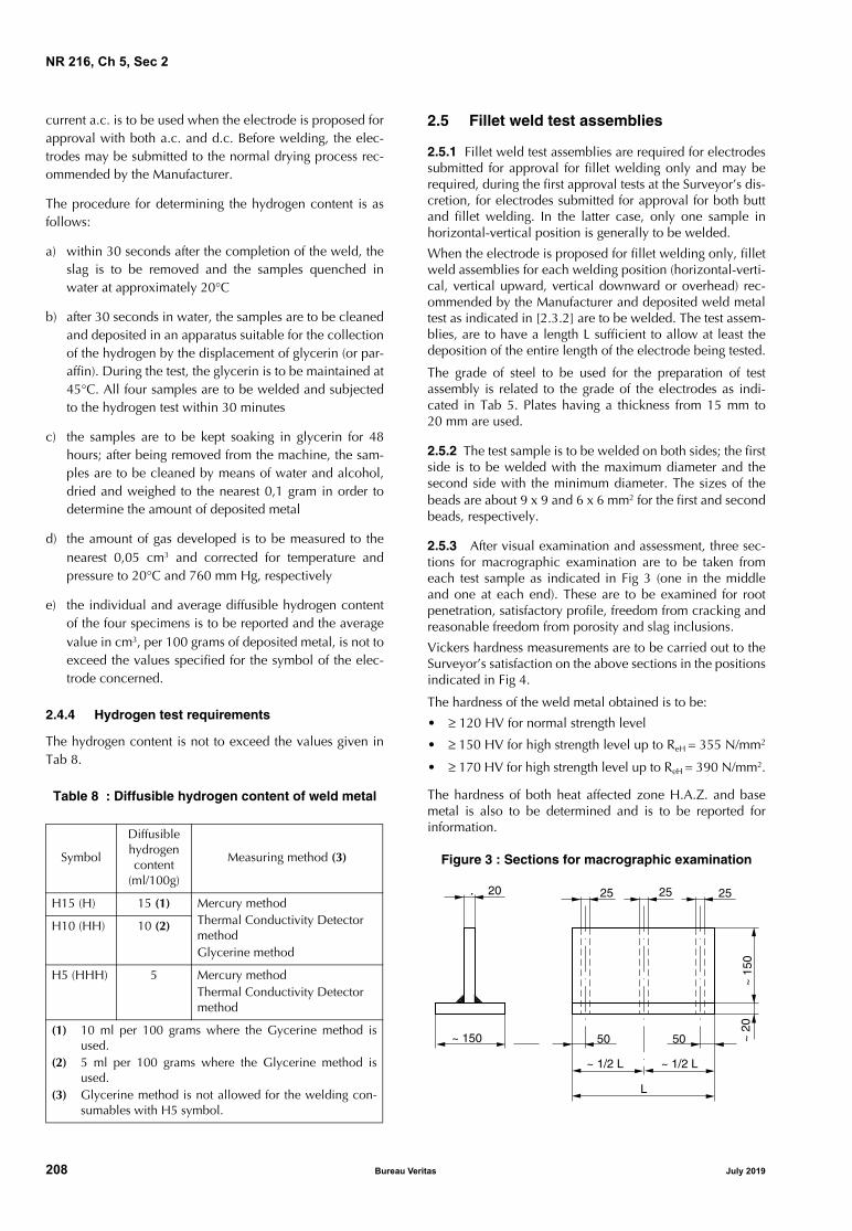
NR 216, Ch 5, Sec 2
current a.c. is to be used when the electrode is proposed forapproval with both a.c. and d.c. Before welding, the elec-trodes may be submitted to the normal drying process rec-ommended by the Manufacturer.
The procedure for determining the hydrogen content is asfollows:
a) within 30 seconds after the completion of the weld, theslag is to be removed and the samples quenched inwater at approximately 20°C
b) after 30 seconds in water, the samples are to be cleanedand deposited in an apparatus suitable for the collectionof the hydrogen by the displacement of glycerin (or par-affin). During the test, the glycerin is to be maintained at45°C. All four samples are to be welded and subjectedto the hydrogen test within 30 minutes
c) the samples are to be kept soaking in glycerin for 48hours; after being removed from the machine, the sam-ples are to be cleaned by means of water and alcohol,dried and weighed to the nearest 0,1 gram in order todetermine the amount of deposited metal
d) the amount of gas developed is to be measured to thenearest 0,05 cm3 and corrected for temperature andpressure to 20°C and 760 mm Hg, respectively
e) the individual and average diffusible hydrogen contentof the four specimens is to be reported and the averagevalue in cm3, per 100 grams of deposited metal, is not toexceed the values specified for the symbol of the elec-trode concerned.
2.4.4 Hydrogen test requirements
The hydrogen content is not to exceed the values given inTab 8.
Table 8 : Diffusible hydrogen content of weld metal
2.5 Fillet weld test assemblies
2.5.1 Fillet weld test assemblies are required for electrodessubmitted for approval for fillet welding only and may berequired, during the first approval tests at the Surveyor’s dis-cretion, for electrodes submitted for approval for both buttand fillet welding. In the latter case, only one sample inhorizontal-vertical position is generally to be welded.
When the electrode is proposed for fillet welding only, filletweld assemblies for each welding position (horizontal-verti-cal, vertical upward, vertical downward or overhead) rec-ommended by the Manufacturer and deposited weld metaltest as indicated in [2.3.2] are to be welded. The test assem-blies, are to have a length L sufficient to allow at least thedeposition of the entire length of the electrode being tested.
The grade of steel to be used for the preparation of testassembly is related to the grade of the electrodes as indi-cated in Tab 5. Plates having a thickness from 15 mm to20 mm are used.
2.5.2 The test sample is to be welded on both sides; the firstside is to be welded with the maximum diameter and thesecond side with the minimum diameter. The sizes of thebeads are about 9 x 9 and 6 x 6 mm2 for the first and secondbeads, respectively.
2.5.3 After visual examination and assessment, three sec-tions for macrographic examination are to be taken fromeach test sample as indicated in Fig 3 (one in the middleand one at each end). These are to be examined for rootpenetration, satisfactory profile, freedom from cracking andreasonable freedom from porosity and slag inclusions.
Vickers hardness measurements are to be carried out to theSurveyor’s satisfaction on the above sections in the positionsindicated in Fig 4.
The hardness of the weld metal obtained is to be:
• ≥ 120 HV for normal strength level
• ≥ 150 HV for high strength level up to ReH = 355 N/mm2
• ≥ 170 HV for high strength level up to ReH = 390 N/mm2.
The hardness of both heat affected zone H.A.Z. and basemetal is also to be determined and is to be reported forinformation.
Figure 3 : Sections for macrographic examination Symbol
Diffusible hydrogen content
(ml/100g)
Measuring method (3)
H15 (H) 15 (1) Mercury methodThermal Conductivity Detector methodGlycerine method
H10 (HH) 10 (2)
H5 (HHH) 5 Mercury methodThermal Conductivity Detector method
(1) 10 ml per 100 grams where the Gycerine method isused.
(2) 5 ml per 100 grams where the Glycerine method isused.
(3) Glycerine method is not allowed for the welding con-sumables with H5 symbol.
2520 2525
~ 150
~ 1
50~
20
50 50
~ 1/2 L ~ 1/2 L
L
208 Bureau Veritas July 2019

NR 216, Ch 5, Sec 2
Figure 4 : Hardness readings
The dimensions are in mm.
2.5.4 The two parts obtained upon sectioning the sampleare to be subjected to fracture as in [2.3.2] after having pre-viously removed the welding bead from one side (on onepart the first and on the other the second deposited beads).
The fractured surfaces are to be examined for root penetra-tion, satisfactory profile, freedom from cracks and reason-able freedom from porosity.
2.5.5 These tests may partially replace the T fillet jointswhen required in [2.3.2].
2.6 Annual control tests
2.6.1 The annual tests are to include at least the following:
a) two deposited metal test assemblies are to prepared inaccordance with [2.3.2] and the required tests (one lon-gitudinal tensile test and 3 Charpy V-notch impact tests)are to be conducted. For electrodes approved for filletweld only, and not suitable for butt-joints, only onedeposited metal test with the maximum diameter is tobe carried out
b) at the discretion of the Society, a butt weld test to bewelded in vertical position may be required in lieu ofthe deposited metal test with electrodes of 4 mm
c) the check of the hydrogen content is required for elec-trodes approved with symbol HHH (or H5) and may berequired for electrodes approved with symbol HH (orH10)
d) the chemical composition may be required to bechecked under conditions corresponding to those of theapproval tests.
The welding and test procedures, the type of current, thematerials, the test results and the re-test procedures, whereapplicable, are regulated by the requirements relative to theapproval tests.
3 Covered electrodes for gravity or contact welding
3.1 Scope
3.1.1 The requirements of this Article apply to coveredelectrodes when submitted for approval for use in gravitywelding, using automatic gravity or similar welding devices.
3.2 Approval tests
3.2.1 Where the electrode is submitted for approval for thegravity welding technique only, deposited metal tests[2.3.2], fillet weld tests [2.5] and, where appropriate, buttweld tests [2.3.3] similar to those for manual electrodes areto be carried out with such technique.
3.2.2 Where the electrode is submitted for approval for thegravity welding technique in addition to normal manualwelding, fillet weld tests and, where appropriate, butt weldtests are to be carried out with the gravity process, in addi-tion to the normal approval tests.
3.2.3 The fillet weld test is to be gravity welded using thelongest size of electrode manufactured. The Manufacturer’srecommended current range is to be reported for each elec-trode size.The results of the tests are to comply with the requirementsspecified in [2.5.3] and [2.5.4].
3.3 Annual control tests
3.3.1 Where the electrode is approved only for gravitywelding, the annual test is to consist of at least one depos-ited weld metal test assembly using such process. If theelectrode is approved also for manual arc welding, theannual test is to be performed as indicated in [2.6.1].
4 Covered electrodes for deep penetration manual welding of C and C-Mn steels
4.1 Scope
4.1.1 The requirements of this Article apply to deep pene-tration electrodes to be used for downhand butt and filletwelding and horizontal-vertical fillet welding.Deep penetration electrodes may be approved as grade 1electrodes only and are to be given the additional symbolD.P.
Approvals limited to butt-joints only may be considered. Inthese cases, the test sample specified in [4.2.2] is notrequired.
4.1.2 The welding of butt-joints in flat position is to be per-formed on square groove edges.When the Manufacturer requires that the approval isextended to cover butt-welded joints having a single Veeedge preparation, all the tests required in [2] for normaltype electrodes used in flat position are to be carried out, inaddition to the tests required in this Article.
20
Base metal
Hardness reading
Base metalHAZ
20
July 2019 Bureau Veritas 209

NR 216, Ch 5, Sec 2
4.1.3 Test samples relative to the approval of deep penetra-tion electrodes are to be welded with the type and theintensity of current recommended by the Manufacturer.
When it is intended that the approval is valid for use withboth d.c. and a.c. currents, the test samples are to bewelded with a.c. current.
4.1.4 As regards the procedure for the approval, the prepa-ration and welding of samples, the specimens and testing,the requirements specified in [2] for ordinary electrodes areto be complied with, in so far as applicable.
4.2 Approval tests
4.2.1 Butt weld test assembly
The following test sample in grade A structural steel orequivalent steel to the Surveyor’s satisfaction is to bewelded:
• one butt-welded sample, with square groove edges,made of two plates having width ≥ 100 mm and a thick-ness equal to twice the diameter of the core of the elec-trode plus 2 mm; such sample is to be welded in flatposition with the maximum electrode diameter forwhich the approval has been requested, with a singlepass on each side (see Fig 5).
The edges are to be accurately cut and in good contact (notmore than 0,25 mm between edges for the full length of thejoint).
The specimens for the following tests are to be taken afterhaving discarded a length of 35 mm from each end:
• two transverse tensile tests
• one face and one root bend
• three Charpy V-notch impact tests
• two macrographic examinations.
4.2.2 Fillet weld test assembly
The following test sample in grade A structural steel orequivalent steel to the Surveyor’s satisfaction is to bewelded:
• one Tee-joint sample having length ≥ 160 mm andthickness about 12-15 mm, to be welded in horizontalposition with a 4 mm electrode on one side and with anelectrode of the maximum diameter to be approved onthe other side.
The edges are to be accurately cut and the gap betweenthe plates is to be not more than 0,25 mm for the fulllength of the joint as shown in Fig 6.
Two cross-sections are to be obtained from the sample atabout 35 mm from each end; the two cross-sections are tobe subjected to a macrographic examination (see Fig 6).
Figure 5 : Deep penetration butt weld test assembly
All the dimensions are in mm.
Figure 6 : Deep penetration fillet weld test assembly
Thickness of plate twicecore of electrode plus 2 mm
Discard
Macro
Charpy V-notch
Face bend
Root bend
Transverse tensile
Discard
Macro
Transverse tensile
0,25 max
100 min. 100 min.
3510
3030
5050
1035
12,5 - 15
Maximum size ofelectrode manufactured
4 mm electrode
0,25
Penetration tobe reported
4 min.
12,5
- 1
5
210 Bureau Veritas July 2019

NR 216, Ch 5, Sec 2
4.2.3 Test requirements
The results required for the tests mentioned in [4.2.1] and[4.2.2] are specified in the following items a) and b):
a) Butt weld test assembly:
• bend tests on a mandrel having diameter equal tothree times the thickness of the sample: bend angleα ≥ 120°
• transverse tensile test: Rm ≥ 410 N/mm2
• impact tests at about +20°C; minimum absorbedenergy (average value of three tests): KV ≥ 47 J
• the macrographic examinations are to show a com-plete compenetration of the welds on the two sides.
b) Fillet weld test assembly:
• the fillet deposited with the 4 mm electrode is toshow a penetration not less than 4 mm (see Fig 6)
• the penetration obtained by the fillet deposited withthe maximum diameter of electrode on the otherside is to be measured and reported for informationpurposes only.
4.2.4 Maximum thickness which can be welded
Upon satisfactory completion of the tests mentioned in theabove paragraphs, the Manufacturer is to prepare and sub-mit to the Society a table showing the maximum thicknesswhich can be welded, with square groove edges, with eachdiameter of electrode included in the approval and with theintensity of current necessary for the relevant electrode.
The table, which forms an integral and essential part of theapproval documentation, is to substantially conform to themaximum thickness value verified in the test in [4.2.1].
4.3 Annual control tests
4.3.1 One test sample, as illustrated in Fig 5 or Fig 6 asapplicable, is required; such sample is to be welded withelectrodes having the maximum approved diameter.
The required tests and the relevant requirements are thoseindicated in [4.2.1], [4.2.2] and [4.2.3]; however, only onetransverse tensile test is required.
For electrodes approved for both normal and deep penetra-tion welding in the downhand position, a deep penetrationweld test, as above, is to be carried out in addition to thedeposited weld metal tests required for normal penetration.
5 Flux-wire combination for submerged arc welding of C and C-Mn steels
5.1 Scope
5.1.1 General
The requirements of this Article apply to wire flux combina-tion for submerged arc welding of hull structural steels, ofthe corresponding grades of steel forgings and castings andof comparable steels intended for other structural applica-tions or pressure systems.
Approvals granted in accordance with these requirementsare valid for standard single wire welding.
Other techniques, such as tandem or multi-wire welding,and one side welding on flux or backing, are to be submit-ted to separate approval tests. These tests are generally to becarried out in accordance with the requirements of this Arti-cle and are detailed, on a case-by-case basis, depending onthe welding procedure proposed.
5.1.2 Type of wires
Types of wires identified by the chemical compositionshown in Tab 9 are generally to be used.
Chemical composition of wires other than those given inTab 9 are to be submitted.
5.1.3 Designation
Wire flux combinations are divided, for the various strengthlevels, into the following grades as defined in [1.2.2]:
a) 1, 2, 3, 4 for normal strength grades
b) 1Y, 2Y, 3Y, 4Y, 5Y for high strength grades with specifiedminimum yield strength up to 355 N/mm2
c) 2Y40, 3Y40, 4Y40, 5Y40 for high strength grades withspecified minimum yield strength up to 390 N/mm2.
The prefix A is added to the grade.
Depending on the welding technique, the following sym-bols are added as a suffix to the grade:
• T for use with two-run technique
• M for use with multi-run technique
• TM for use with both techniques.
5.1.4 Information and documentation to be submitted
The following information and supporting documentation,as applicable, are generally to be submitted together withthe request for approval:
a) commercial name of the flux, for which the approval isrequested; type of flux (fused or conglomerate)
b) commercial name of the associated wire, limits ofchemical composition and diameters to be approved
c) grading under which the approval is requested; type ofcurrent and welding positions
d) typical chemical composition of the deposited metal,with particular reference to the contents of Mn, Si andalloying elements
e) recommendations, where applicable, regarding therange of the welding parameters (current, voltage andwelding speed)
f) previous approvals granted to the proposed wire-fluxcombination.
July 2019 Bureau Veritas 211
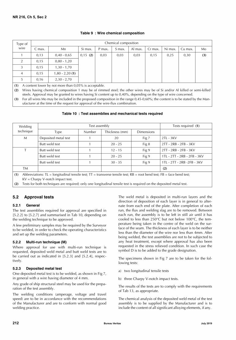
NR 216, Ch 5, Sec 2
Table 9 : Wire chemical composition
Table 10 : Test assemblies and mechanical tests required
5.2 Approval tests
5.2.1 General The test assemblies required for approval are specified in[5.2.2] to [5.2.7] and summarised in Tab 10, depending onthe welding technique to be approved.
A few preliminary samples may be required by the Surveyorto be welded, in order to check the operating characteristicsand set up the welding parameters.
5.2.2 Multi-run technique (M)Where approval for use with multi-run technique isrequested, deposited weld metal and butt weld tests are tobe carried out as indicated in [5.2.3] and [5.2.4], respec-tively.
5.2.3 Deposited metal testOne deposited metal test is to be welded, as shown in Fig 7,in general with a wire having diameter of 4 mm.
Any grade of ship structural steel may be used for the prepa-ration of the test assembly.
The welding conditions (amperage, voltage and travelspeed) are to be in accordance with the recommendationsof the Manufacturer and are to conform with normal goodwelding practice.
The weld metal is deposited in multi-run layers and thedirection of deposition of each layer is in general to alter-nate from each end of the plate. After completion of eachrun, the flux and welding slag are to be removed. Betweeneach run, the assembly is to be left in still air until it hascooled to less than 250°C but not below 100°C, the tem-perature being taken in the centre of the weld on the sur-face of the seam. The thickness of each layer is to be neitherless than the diameter of the wire nor less than 4mm. Afterbeing welded, the test assemblies are not to be subjected toany heat treatment, except where approval has also beenrequested in the stress relieved condition. In such case thesymbol D is to be added to the grade designation.
The specimens shown in Fig 7 are to be taken for the fol-lowing tests:
a) two longitudinal tensile tests
b) three Charpy V-notch impact tests.
The results of the tests are to comply with the requirementsof Tab 13, as appropriate.
The chemical analysis of the deposited weld metal of the testassembly is to be supplied by the Manufacturer and is toinclude the content of all significant alloying elements, if any.
Type of wire
Chemical composition
C max. Mn Si max. P max. S max. Al max. Cr max. Ni max. Cu max. Mo
1 0,13 0,40 - 0,65 0,15 (2) 0,03 0,03 0,03 0,15 0,25 0,30 (3)
2 0,15 0,80 - 1,20
3 0,15 1,30 - 1,70
4 0,15 1,80 - 2,20 (1)
5 0,16 2,30 - 2,70
(1) A content lower by not more than 0,05% is acceptable.(2) Wires having chemical composition 1 may be of rimmed steel; the other wires may be of Si and/or Al killed or semi-killed
steels. Approval may be granted to wires having Si content up to 0,40%, depending on the type of wire concerned.(3) For all wires Mo may be included in the proposed composition in the range 0,45-0,60%; the content is to be stated by the Man-
ufacturer at the time of the request for approval of the wire-flux combination.
Welding technique
Test assembly Tests required (1)
Type Number Thickness (mm) Dimensions
M Deposited metal test 1 20 Fig 7 2TL - 3KV
Butt weld test 1 20 - 25 Fig 8 2TT - 2RB - 2FB - 3KV
T Butt weld test 1 12 - 15 Fig 9 2TT - 2RB - 2FB - 3KV
Butt weld test 1 20 - 25 Fig 9 1TL - 2TT - 2RB - 2FB - 3KV
Butt weld test 1 30 - 35 Fig 9 1TL - 2TT - 2RB -2FB - 3KV
TM (2)
(1) Abbreviations: TL = longitudinal tensile test; TT = transverse tensile test; RB = root bend test; FB = face bend test;KV = Charpy V-notch impact test.
(2) Tests for both techniques are required; only one longitudinal tensile test is required on the deposited metal test.
212 Bureau Veritas July 2019

NR 216, Ch 5, Sec 2
Figure 7 : Deposited metal test
All the dimensions are in mm, unless otherwise indicated.
5.2.4 Butt weld tests for multi-run technique
One butt weld test assembly is to be welded as shown inFig 8 in general with a wire having diameter of 4 mm.
The grade of steel to be used for the preparation of the testassemblies is related to the grade of the wire-flux combina-tion as indicated in Tab 11.
At the discretion of the Society, approval of multi-run weld-ing of both normal and higher strength steel may beobtained by making a butt weld on higher tensile steel only.
For flux to be approved under grades 4 and 5, in lieu of thehull steels specified in Tab 11, C-Mn steels for pressure ves-sels of grades L40 and L60, respectively, and strength appro-priate to the wire flux combination strength may be used.
The use of other types of steel is to be agreed with the Soci-ety on a case-by-case basis.
The welding is to be performed by the multi-run techniqueand the welding conditions are to be the same as thoseadopted for the deposited weld metal assembly. The backsealing run is to be made with the welding parameters usedfor the filling pass, after back gouging to sound metal.
After being welded, the test assemblies are not to be sub-jected to any heat treatment except where approval has alsobeen requested in the stress relieved condition [5.2.7]. Insuch case the symbol D is to be added to the grade designa-tion.
It is recommended that the welded assemblies should besubjected to a radiographic examination to ascertain if thereare any defects in the weld prior to the preparation of testspecimens.
The test specimens, shown in Fig 8, are to be taken for thefollowing tests:
a) two transverse tensile tests
b) three Charpy V-notch impact tests
c) two root and two face bend tests.The results of the tests are to comply with the requirementsof [5.2.6], as appropriate.
Table 11 : Grade of steel used for test assemblies
Figure 8 : Butt weld test assembly
All the dimensions are in mm, unless otherwise indicated.
200
10˚
2012
16
50
Tack weld
Tensile
30
1010101010
Impact
Line of cut
Tensile
30
Wire flux combination grade
Steel grade (1)
1 A
2 A, B, D
3 - 4 A, B, D, E
1Y AH 32-36
2Y AH 32-36, DH 32-36
3Y AH32-36, DH32-36, EH32-36
4Y - 5Y AH32-36, DH32-36, EH32-36, FH32-36
2Y40 AH40, DH40
3Y40 AH40, DH40, EH40
4Y40 - 5Y40 AH40, DH40, EH40, FH40
(1) The tensile strength of grades AH32 to FH32 is to begreater than 490 N/mm2.
Impact3 Charpy-VTest-pieces
Tensile
Tensile
Bend
Bend
Bend
Bend
Discard
Discard
60˚
4 20
150 mm150 mm
50
30
30
30
30
50
10
10
10
July 2019 Bureau Veritas 213

NR 216, Ch 5, Sec 2
Figure 9 : Butt weld test assemblyfor two-run technique
All the dimensions are in mm.
5.2.5 Two-run technique (T)Where approval for use with two-run technique only isrequested, two butt weld test assemblies are to be carriedout as indicated in Tab 12 and no deposited metal test isrequested.
The grade of steel to be used for the preparation of the testassemblies is related to the grade of the wire flux combina-tion as indicated in Tab 11.
Each strength level requires separate approval.
For flux to be approved under grades 4 and 5, in lieu of thehull steels specified in Tab 11, C-Mn steels for pressure ves-sels of grades L40 and L60, respectively, and strength appro-priate to the wire flux combination strength may be used.
The use of other types of steel is to be agreed with the Soci-ety on a case-by-case basis.
The welding is to be performed in two runs, one from eachside, using voltage and travel speed in accordance with therecommendation of the Manufacturer and normal goodwelding practice. In general, the following values of currentparameters are to be complied with for welding the secondrun:• 700-800 A for samples having thickness 12-15 mm• 900-1000 A for samples having thickness 20-25 mm• 1100-1200 A for samples having thickness 30-35 mm.
After the completion of the first run, the flux and weldingslag are to be removed and the assembly left in still air untilit has cooled to 100°C, the temperature being taken in thecentre of the weld, on the surface of the seam.
After being welded, the test assemblies are not to be sub-jected to any heat treatment except where approval has alsobeen requested in the stress relieved condition. In such casethe symbol D is to be added to the grade designation.
The test assemblies are to be subjected to radiographicexamination to ascertain freedom from lack of penetrationor other defects in the weld, prior to the preparation of testspecimens.
The test specimens, shown in Fig 9, are to be taken for thefollowing tests:
a) two transverse tensile tests
b) three Charpy V-notch impact tests
c) two root and two face bend tests.
Where the approval is required for two-run technique only,one longitudinal tensile specimen is to be taken from thethicker plate, as shown in Fig 9.
The results of the tests are to comply with the requirementsof [5.2.6], as appropriate.
The chemical analysis of the weld metal of the second runin each test assembly is to be supplied by the Manufacturerand is to include the content of all significant alloying ele-ments, if any.
5.2.6 Tests requirements
The required results of tensile and impact tests on depositedmetal and butt weld tests are indicated in Tab 13.
Bend tests are to be performed on a mandrel having a diam-eter equal to three times the thickness of the specimen; theresults are to comply with requirements in [1.5.3].
5.2.7 Approval in the stress relieved condition
When the approval of the wire flux combination is requiredwith the additional symbol D, relevant to the checking ofthe mechanical properties in the stress relieved condition,the following additional tests are to be carried out on sam-ples submitted to stress relieving in the furnace for one hourat 600-650°C:
a) Two-run technique (T)
• one longitudinal and one transverse tensile test,three Charpy V-notch impact tests on the face androot side of the butt welded assembly having themaximum thickness.
b) Multi-run technique (M)
• one longitudinal tensile test on the deposited metaltest and one transverse tensile test on the butt weldtest
• three Charpy V-notch impact tests on depositedmetal and butt weld tests.
Min. 150 Min. 150
Tensile specimen
Bend specimen
Impactspecimen
50
30 mm for plates upto 25 mm thickness
10
30
50
Bend specimen
Tensile specimen
Longitudinaltensile(cylindricalspecimen)
2 nd run2 max
10
10
10
Bend specimen 30
30Bend specimen
214 Bureau Veritas July 2019

NR 216, Ch 5, Sec 2
Table 12 : Two-run technique butt weld test assemblies
Figure 10 : Recommended edge preparation for two-run technique
Table 13 : Required mechanical properties
5.3 Annual control tests
5.3.1 The periodical control tests are to include at least thefollowing:
a) two-run technique (T)• one butt weld test assembly with plate thickness 20-
25 mm from which one transverse tensile, two bendtests (one root and one face bend) and three impacttests are to be taken. One longitudinal tensile test isalso to be prepared for wire flux combinationsapproved solely for the two-run technique.
b) multi-run technique (M)
• one deposited metal test assembly from which oneall weld metal longitudinal tensile test and threeCharpy V-notch impact tests are to be taken.
c) T and M techniques (TM)
• the test assemblies and relevant tests required for Tand M techniques are to be carried out. The longitu-dinal tensile test specified in a) for T technique is notrequired.
Grade Plate thickness (mm) Recommended preparation (2) Maximum diameter of wire (mm)
1 - 1Y 12 - 15 Fig 10 (a) 5
20 - 25 Fig 10 (b) 6
2, 3, 4, 2Y, 3Y, 4Y, 5Y, 20 - 25 (1) Fig 10 (b) 6
2Y40, 3Y40, 4Y40, 5Y40 30 - 35 (1) Fig 10 (c) 7
(1) A limitation of the approval to the lower and medium thickness range (up to the maximum welded plate thickness) may beagreed to by the Society and the test pieces are then to be welded from plates of thickness 12-15 mm and 20-25 mm, irrespec-tive of the quality grade.
(2) Minor deviations in the weld preparation are admissible; the root gap is to be practically constant and generally is not to exceed0,7 mm.
Grade
Tensile test on deposited metal Tensile test on butt weld Charpy V-notch impact test
Yield stress ReH
(N/mm2) min.Tensile strength
Rm (N/mm2)Elong. A5 (%) min.
Tensile strength Rm
(N/mm2) min.Test temp.
(°C)Minimum average
energy (J)
1 305 400 - 560 22 400 + 20 34
2 0
3 − 20
4 − 40
1Y 375 490 - 660 22 490 + 20 34
2Y 0
3Y − 20
4Y − 40
5Y − 60
2Y40 400 510 - 690 22 510 0 39
3Y40 − 20
4Y40 − 40
5Y40 − 60
12
15
8
12
(a)
60˚ 70˚
(b)
30
35
70˚
8
12
(c)20
2
5
July 2019 Bureau Veritas 215

NR 216, Ch 5, Sec 2
5.3.2 The weld and test procedures, the type of current, thematerials, the test results and the re-test procedures, whereapplicable, are regulated by the requirements relative to theapproval tests.
Where a wire flux combination is approved for weldingboth normal strength and higher strength steels, the steels ofthe highest strength approved are to be used for the prepa-ration of the butt weld assembly required by the T tech-nique, in order to also cover the lower strength levels.
6 Flux-wire combinations for one side submerged arc welding of butt-joints of C and C-Mn steels
6.1 Scope
6.1.1 The requirements of this Article apply to flux- wirecombinations for submerged-arc welding processes withhigh current, used for one side welding (U welding tech-nique) of butt-joints with one or more layers (in general notmore than two layers).
The welding machine may have one or more weldingheads. A suitable backing support, for example a flux layerand support equipment, may be adopted.
The requirements of Article [5] are also to be compliedwith, as applicable, unless otherwise stated in this Article.
6.2 Designation
6.2.1 The prefix A and the suffix U are added to the gradeas defined in [1.2.7].
6.3 Approval tests
6.3.1 The edge preparation of the various samples and thewelding parameters to be used are those proposed by theManufacturer and they are to be reported in the approvalcertificate; they are to be appropriate to ensure completefusion and satisfactory surface appearance.
The specimens which are required to be obtained from thesamples are the same as indicated in [5.2.5] except forimpact test specimens, which are to be taken as follows (seeFig 11):
a) for samples of thickness s = 12-15 mm:
3 specimens at mid-thickness
b) for samples of thickness s = 20-25 mm:
6 specimens, 3 near each surface
c) for samples of thickness s = 30-35 mm:
9 specimens, 3 near each surface and 3 at mid-thick-ness.
Figure 11 : Position of Charpy V-notch impact testfor one side automatic welding
7 Wires and wire-gas combination for semiautomatic welding of C andC-Mn steels
7.1 Scope
7.1.1 The requirements of this Article apply to bare wiregas combinations and flux cored or flux coated wires withor without shielding gases, to be used for semiautomaticwelding of hull structural steels, of the correspondinggrades of steel forgings and castings and of comparablesteels intended for other structural applications or pressuresystems.The term semiautomatic is used to describe processes inwhich the weld is made manually by a welder holding agun through which the wire is continuously feed. For thepurpose of the approval designation, this technique is iden-tified by the symbol S or SA.
7.2 Type of wires
7.2.1 The chemical composition of bare wires normallyused is shown in Tab 14.
Types G3Si1 and G4Si1 are particularly intended for weld-ing processes under CO2 shielding gas and the other typesfor welding processes where mixtures of shielding gases areused.
Chemical composition of wires other than those given inTab 14 are to be submitted to the society.
7.3 Shielding gases
7.3.1 Where applicable, the composition of the weldinggas is to be reported.
For the purpose of the approval, the type of gas and mixtureof gas are grouped as indicated in Tab 15.
Unless otherwise required for specific applications, gasmixtures in the same group are considered equivalent forapproval purposes.
2
10
10
2
2
2
10
10
10
30
35
20
25
216 Bureau Veritas July 2019

NR 216, Ch 5, Sec 2
Table 14 : Solid wire chemical composition
Table 15 : Composition of gas mixturesfor continuous wire welding process
7.4 Designation
7.4.1 Wire gas combinations are divided, for the variousstrength levels, into the following grades as defined in[1.2.2]:
a) 1, 2, 3, 4 for normal strength grades
b) 1Y, 2Y, 3Y, 4Y, 5Y for high strength grades with specifiedminimum yield strength up to 355 N/mm2
c) 2Y40, 3Y40, 4Y40, 5Y40 for high strength grades withspecified minimum yield strength up to 390 N/mm2.
The prefix S or SA is added to indicate semiautomatic weld-ing technique.
7.4.2 Flux cored or flux coated wires may be required to besubmitted to the hydrogen test as detailed in [2.4], using theManufacturer’s recommended welding conditions and
adjusting the deposition rate to give a weight of welddeposit per sample similar to that deposited when usingmanual electrodes.
On the basis of the test results, the welding consumablesmay be given one of the symbols H (or H15), HH (or H10),HHH (or H5), as appropriate.
7.5 Information and documentation to be submitted
7.5.1 The following information and supporting documen-tation, as appropriate, are generally to be submittedtogether with the request for approval:
a) commercial name, type of wire, limits of chemical com-position in the case of bare wires
b) grading under which the approval is requested; type ofcurrent, welding positions
c) type of shielding gas or gas mixture; commercial brandand Manufacturer, in the case of gas mixtures of specialtypes
d) typical chemical composition of the deposited metal,with particular reference to the contents of Mn, Si andalloying elements
e) recommendations, where applicable, regarding therange of the welding parameters (current, voltage andwelding speed)
f) previous approvals granted to the proposed gas wirecombination.
7.6 Approval tests
7.6.1 General
Deposited metal and butt weld tests are to be performed asindicated in [7.6.2] and [7.6.3], and summarised in Tab 16.
A few preliminary samples may be required by the Surveyorto be welded, in order to check the operating characteristicsand set up the welding parameters. These tests may be lim-ited to the fillet test assemblies required in [7.6.7].
Type of wire
Chemical composition (%) (2)
C max Mn Si P max S max Cr max Ni max Cu max (1) Mo
G2Si 0,14 0,90 - 1,30 0,50 - 0,80 0,025 0,025 0,15 0,15 0,35 −
G3Si1 0,14 1,30 - 1,60 0,70 - 1,00
G4Si1 0,14 1,60 - 1,90 0,80 - 1,20
G4Mo 0,14 1,70 - 2,10 0,50 - 0,80 0,40 - 0,60
G4Si 0,14 1,60 - 1,90 0,80 - 1,20 −
(1) Including surface lining(2) Al, Ti, Zr may be added by the Manufacturer and the values are to be submitted to the Society for consideration at the time of
the request for the approval; reference may be made to the limits of EN 440.
Group symbol
Composition of gas mixtures in volume (%)
Ar (1) H2 CO2 O2
C 1 100 −
C2 70 - 99 1 - 30
M11 90 - 98 1 - 5 1 - 5 −
M12 95 - 99 1 - 5 −
M13 97 - 99 − − 1 - 3
M14 92 - 98 − 1 - 5 1 - 3
M21 75 - 94 − 6 - 25 −
M22 90 - 96 − − 4 - 10
M23 67 - 93 − 6 - 25 1 - 8
M31 50 - 74 − 26 - 50 −
M32 85 - 89 − − 11 - 15
M33 35 - 85 − 6 - 50 9 - 15
(1) Argon may be replaced by Helium up to 95% of theargon content.
July 2019 Bureau Veritas 217

NR 216, Ch 5, Sec 2
Table 16 : Test assemblies and mechanical tests required
7.6.2 Deposited metal test
Two deposited metal test assemblies are to be welded in theflat position as shown in Fig 1, one using a wire of 1,2mmor the smallest size to be approved and the other using awire of 2,4 mm or the largest size to be approved. If onlyone diameter is available, one test assembly is sufficient.Any grade of hull structural steel may be used for the prepa-ration of the test assembly.
The preparation is to be in accordance with Fig 1; however,the angle of the bevel and the gap at the root may be modi-fied depending on the welding process.
The weld metal is to be deposited in multi-run layers accord-ing to the normal practice (with wide beads extending for thefull width of the bevel), as far as this is correctly feasible,regardless of the diameter of the wire; the direction of deposi-tion of each layer is in general to alternate from each end ofthe plate, each run of weld metal having thickness in the range2 mm to 6 mm (compenetration included). Between each runthe assembly is to be left in still air until it has cooled to lessthan 250°C but not below 100°C, the temperature being takenin the centre of the weld on the surface of the seam. Afterbeing welded, the test assemblies are not to be subjected toany heat treatment except where approval has also beenrequested in the stress relieved condition. In such case thesymbol D is to be added to the grade designation.
The specimens shown in Fig 1 are to be taken for the fol-lowing tests:
a) one longitudinal tensile test
b) three Charpy V-notch impact tests.
The chemical analysis of the deposited weld metal in each testassembly is to be supplied by the Manufacturer and is toinclude the content of all significant alloying elements, if any.
In general the chemical composition (C, Mn, Si) is deter-mined near the surface of the final pass and is to bereported for information.
7.6.3 Butt weld testsButt weld test assemblies as shown in Fig 12 are to bewelded for each welding position (flat, horizontal, verticalupwards and downwards and overhead) for which the wiregas combination is to be approved.
One test sample is to welded in downhand position using,for the first run, a wire of 1,2 mm or the smallest diameter tobe approved and, for the remaining runs, wires of the maxi-mum diameter to be approved.
Where wires are intended for flat position only, one addi-tional test sample is to be welded, if possible using wires ofdifferent diameters from those required above. Where onlyone diameter is manufactured, only one downhand buttweld assembly is to be prepared.
The other test assemblies are to be welded in the verticalupwards, downwards, horizontal and overhead positions,using for the first run a wire of 1,2 mm or the smallest diam-eter to be approved, and for the remaining runs the largestdiameter to be approved for the position concerned.
The grade of steel to be used for the preparation of the testassemblies is related to the grade of the electrodes as indi-cated in Tab 5.
For the wires or flux-cored wires to be approved undergrades 4 and 5, in lieu of the hull steels specified in Tab 5,C-Mn steels for pressure vessels of grades L40 and L60,respectively, and strength appropriate to the electrodestrength may be used.
The use of other types of steel is to be agreed with the Soci-ety on a case-by-case basis.
Test assemblyTests required (1)
TypeWelding position
(2)Wire diameter
(mm)Number of
samples Thickness
(mm)Dimensions
Deposited metal
Flat Max. 1 (3) 20 Fig 1 1 TL - 3KV
1,2 or min. 1
Butt weld Flat First run: 1,2 or min.Remaining run: max
1 (4) 15 - 20 Fig 12 1TT - 1RB - 1FB - 3KV
Vertical upward 1 1TT - 1RB - 1FB - 3SB - 3KV
Vertical downward 1 1TT - 1RB - 1FB - 3SB - 3KV
Horizontal 1 1TT - 1RB - 1FB - 3SB - 3KV
Overhead 1 1TT - 1RB - 1FB - 3SB - 3KV
Fillet (5) First side: min. diam. 1 15 - 20 [2.5] Fig 3 Fig 4
Macro-Fracture-Hardness
Second side: max. diam.
(1) Abbreviations: TL = longitudinal tensile test; TT = transverse tensile test; RB = root bend test; FB = face bend test;SB = side bend test; KV = Charpy V-notch impact test.
(2) When the approval is requested only for one or more specified welding positions, the butt test samples are to be welded in such positions.
(3) If only one diameter is to be approved, only one test assembly is required. (4) When the approval is requested in flat position only, two test samples are to be welded - the first sample with the maximum
wire diameter and the second with increasing diameter from the first to the last pass. (5) Fillet weld samples are to be welded in the position required for approval.
218 Bureau Veritas July 2019

NR 216, Ch 5, Sec 2
Figure 12 : Butt weld test assembly
All the dimensions are in mm.
The welding is to be performed with the usual technique incompliance with requirements specified in [7.6.2] for thedeposited metal test, as applicable. For all assemblies, theback sealing run is to be made with the same diameter ofwire or with the largest diameter of wire used for the weldon the other side.
After being welded, the test assemblies are not to be sub-jected to any heat treatment except where approval has alsobeen requested in the stress relieved condition. In such casethe symbol D is to be added to the grade designation.
It is recommended and may be required that the weldedassemblies should be subjected to a radiographic examina-tion to ascertain if there are any defects in the weld prior tothe preparation of test specimens.
The specimens shown in Fig 12 are to be taken for the fol-lowing tests:
a) one transverse tensile test
b) three Charpy V-notch impact tests
c) one face and one root bend tests.
Three additional side bend tests [1.5.4] may be required bythe Surveyor to be carried out for samples welded in verti-cal, horizontal and overhead positions.
7.6.4 Test requirementsThe required results of tensile and impact tests on depositedmetal and butt weld tests are indicated in Tab 17.
Bend tests are to be performed on a mandrel having a diam-eter equal to three times the thickness of the specimen; theresults are to comply with the requirements in [1.5.3].
7.6.5 Approval in the stress relieved condition The requirements set forth in [2.3.5] apply.
7.6.6 Tests for checking the hydrogen content When the additional symbols HH (or H10) or HHH (or H5)are required, the provisions under [2.4] apply.
7.6.7 Fillet weld test assembliesFillet weld test assemblies are generally required in addition tothe butt weld test and are to be welded in each of the positionsapplied for approval (horizontal-vertical, vertical, overhead).The requirements set forth in [2.5] apply, as appropriate.
7.7 Annual control tests
7.7.1 The annual tests are to include at least the followingassemblies and tests:
a) One deposited metal test assembly is to be welded inaccordance with [7.6.2] with wire having diameterwithin the range approved, and the required tests (onelongitudinal tensile test and three Charpy V-notchimpact tests) are to be conducted.
b) At the discretion of the Society, a butt weld test, to bewelded in vertical position, may also be required andthree side bend tests and three Charpy V-notch impacttests are to be performed.
c) For flux cored wire electrodes approved with symbolHH (or H10) or HHH (or H5), the hydrogen contentmay be required to be checked with the same procedureused in the approval tests.
d) The chemical composition may be required to bechecked under conditions corresponding to those of theapproval tests.
The weld and test procedures, the type of current, the mate-rials, the test results and the re-test procedures, where appli-cable, are regulated by the requirements relative to theapproval tests.
8 Wires and wire-gas combinations for automatic welding of C and C-Mn steels
8.1 Scope
8.1.1 GeneralThe requirements of this Article apply to bare wire-gas combi-nations and flux cored or flux coated wires with or withoutshielding gases to be used for automatic welding processeswith multi-run technique (M) and two-run technique (T).
As regards preliminary information and requirements notexpressly stated in this Article, reference may be made as faras applicable to the corresponding requirements of Article [7].
150 150
S.B.
T.T.
F.B.
R.B.
M.
KV.
S.B.
KV.
~ 200
10 S.B.
discard
20sp
are
July 2019 Bureau Veritas 219

NR 216, Ch 5, Sec 2
Table 17 : Mechanical properties
8.2 Designation
8.2.1 Wire gas combinations are divided, for the variousstrength levels, into the following grades as defined in[1.2.2]:
a) 1, 2, 3, 4 for normal strength grades
b) 1Y, 2Y, 3Y, 4Y, 5Y for high strength grades with specifiedminimum yield strength up to 355 N/mm2
c) 2Y40, 3Y40, 4Y40, 5Y40 for high strength grades withspecified minimum yield strength up to 390 N/mm2.
The prefix A is added to indicate automatic welding tech-nique.
8.3 Approval tests
8.3.1 General
Test samples for the approval are to be carried out using thewelding technique for which approval is requested (multi-run M or two-run T technique).
In the case of the multi-run welding technique using wirediameters approved with the semiautomatic process, thetests are not to be repeated with the automatic process.
8.3.2 Multi-run technique
Where approval for use with the multi-run technique (M) isrequested, deposited weld metal and butt weld tests are tobe carried out as indicated in [8.3.3] and [8.3.4], respec-tively.
8.3.3 Deposited metal test
One deposited metal test is to be welded as shown in Fig 7;The base metal, the preparation of the test assembly weld-ing, the checks and the number of tests required are to be asindicated in [5.2.3], except that the thickness of each layeris to be not less than 3 mm.
The wire diameter, type of current and welding parametersare to be in accordance with the recommendation of theManufacturer.
The results of the tests are to comply with the requirementsof Tab 18.
8.3.4 Butt weld tests for multi-run technique
One butt weld assembly is to be welded as shown in Fig 8for each position to be approved; the base metal, the prepa-ration of the test assembly welding, the checks and thenumber of test specimens required are to be as indicated in[5.2.4].
The diameter of the wire, type of current and weldingparameters are to be in accordance with the recommenda-tion of the Manufacturer.
The results of the tests are to comply with the requirementsof Tab 18.
8.3.5 Two-run technique
Where approval for use with the two-run technique only (T)is requested, two butt weld test assemblies are to be carriedout and no deposited metal test is requested.
The indications in [5.2.5] generally apply if not modifiedbelow, except that one test assembly is to be 12-15 mmthick and the other is to be 20 mm thick.
Grade
Tensile test on deposited metal Tensile test on butt
weldCharpy V-notch impact testMinimum average energy (J)
Yield stress ReH
(N/mm2) min.Tensile strength
Rm (N/mm2)Elong. A5
(%) min.Tensile strengthRm (N/mm2) min.
Test temp.(°C)
Flat, Horizontal,Overhead
Vertical
1 305 400 - 560 22 400 + 20 47 34
2 0
3 − 20
4 − 40
1Y 375 490 - 660 22 490 + 20 47 34
2Y 0
3Y − 20
4Y − 40
5Y − 60
2Y40 400 510 - 690 22 510 0 47 39
3Y40 − 20
4Y40 − 40
5Y40 − 60
220 Bureau Veritas July 2019

NR 216, Ch 5, Sec 2
Table 18 : Mechanical properties
The bevel preparation of the test assemblies is to be asshown in Fig 13. Small deviations in the edge preparationmay be allowed according to the Manufacturer’s recom-mendations.
If approval is requested for welding plates thicker than20 mm, one assembly is to be prepared with plates 20 mmthick and the other with the maximum thickness for whichthe approval is requested. For assemblies using plates over25 mm in thickness, the edge preparation used is to bereported for information.
The base metal, checks and number of test specimensrequired are to be as indicated in [5.2.5].
The diameter of the wire, type of current and weldingparameters are to be in accordance with the recommenda-tion of the Manufacturer.
The results of the tests are to comply with the requirementsof Tab 18.
8.4 Annual control tests
8.4.1 Multi-run technique
The annual tests are to include at least the following:
a) One deposited metal test assembly is to be welded inaccordance with [8.3.3] with wires having minimum ormaximum diameter, and the required tests (one longitu-dinal tensile test and three Charpy-V notch impact tests)are to be conducted.
b) The chemical composition may be required to bechecked under conditions corresponding to those of theapproval tests.
8.4.2 Two-run technique
The annual tests are to include at least the following:
a) One butt weld test assembly is to be welded in accor-dance with [8.3.5] with wires having minimum or maxi-mum diameter, and the required tests (one transversetensile test, three Charpy V-notch impact tests and two
bend tests) are to be performed. One longitudinal ten-sile test is also required when the wire is approved forthe two-run technique only.
b) The chemical composition may be required to bechecked under conditions corresponding to those of theapproval tests.
8.4.3 Test requirements The weld and test procedures, the type of current, the mate-rials, the test results and the re-test procedures, where appli-cable, are regulated by the requirements relative to theapproval tests.
For flux cored wire electrodes approved with symbol HH(or H10) or HHH (or H5), the hydrogen content may berequired to be checked with the same procedure used in theapproval tests.
Figure 13 : Recommended edge preparationfor two-run butt weld test assemblies
Grade
Longitudinal tensile test Transverse tensile test Charpy V-notch impact test
Yield stress ReH
(N/mm2) min.Tensile strength
Rm (N/mm2)Elong. A5 (%) min.
Tensile strength Rm
(N/mm2) min.Test temp.
(°C)Minimum average
energy (J)
1 305 400 - 560 22 400 + 20 34
2 0
3 − 20
2Y 375 490 - 660 22 490 0 34
3Y − 20
4Y − 40
5Y − 60
2Y40 400 510 - 690 22 510 0 39
3Y40 − 20
4Y40 − 40
5Y40 − 60
60˚
60˚
8
6
CL
60˚
12
15
20
25
July 2019 Bureau Veritas 221

NR 216, Ch 5, Sec 2
9 Consumables for welding C and C-Mn steels with electrogas or electroslag process
9.1 Scope
9.1.1 General
The requirements of this Article apply to wire gas combina-tions and flux cored or flux coated wires for electrogas (EG)and electroslag (ES) vertical welding with or without con-sumable nozzles of hull structural steels, of the correspond-ing grades of steel forgings and castings and of comparablesteels intended for other structural applications.
9.1.2 Type of wires
The wires are to be of the type recommended by the Manu-facturer, obtained from original packages and of knownchemical composition.
For electrogas processes, wires having the chemical compo-sition specified in Tab 14 may be used. Other wires of dif-ferent chemical composition are to be submitted forconsideration.
9.1.3 Shielding gases
The requirements specified in [7.3.1] apply.
9.1.4 Designation
The consumables are divided, for the various strength lev-els, into the following grades as defined in [1.2.2]:
a) 1, 2, 3 for normal strength grades
b) 2Y, 3Y, 4Y for high strength grades with specified mini-mum yield strength up to 355 N/mm2
c) 2Y40, 3Y40, 4Y40 for high strength grades with speci-fied minimum yield strength up to 390 N/mm2.
The prefix AV is added to the grade to indicate electrogas orelectroslag welding technique.
For high strength grades, the approval may be restricted foruse with steels of specific composition. This applies, in par-ticular, in relation to the content of grain refining elements,and if general approval is required, a Niobium treated steelis to be used for approval tests.
9.2 Information and documentation to be submitted
9.2.1 Information and documentation to be submitted
The following information and supporting documentationare to be submitted together with the request for approval:
a) commercial name, type of wire, limits of chemical com-position in the case of bare wires
b) type of process and grading under which the approval isrequested
c) type of shielding gas or gas mixture; commercial brandand Manufacturer, in the case of gas mixtures of specialtypes
d) type of flux, consumable insert when used
e) type of current, range of current for which the approvalis requested
f) main characteristics of the welding equipment
g) typical chemical composition of the deposited metal
h) main operating characteristics and welding techniques,associated recommendations and limitations in generaland in particular as regards edge preparation and weld-ing parameters
i) previous approvals already granted to the proposed con-sumables.
9.3 Approval tests
9.3.1 Two butt weld test assemblies are to be prepared: onewith plates 20/25 mm thick, the other with plates 35/40 mmthick or more.
The grade of steel to be used for each of these assemblies isto be selected according to the requirements given in Tab11 for submerged arc welding.
The chemical composition of the plate, including the con-tent of grain refining elements, is to be reported.
The welding conditions and the edge preparation adoptedare to be in accordance with the recommendation of theManufacturer and are to be reported.
The Manufacturer’s maximum recommended gap betweenplates is to be used in making the test assemblies.
It is recommended that the welded assemblies be subjectedto radiographic and or ultrasonic examination to ascertainthe absence of defects prior to the preparation of test speci-mens.
The specimens shown in Fig 14 are to be taken for the fol-lowing tests:
a) two longitudinal tensile tests
b) two transverse tensile tests
c) two side bend tests
d) two sets of three Charpy V-notch impact tests with notchlocated as shown in Fig 15 (i.e. one set with the notchlocated in the centre of the weld and one set with thenotch located at 2 mm from the fusion line in the weldmetal)
e) two macro sections (in the middle of the sample andtowards the end) and, if required, Vickers hardnesschecks.
The chemical analysis of the deposited weld metal is to besupplied by the Manufacturer and is to include the contentof all significant alloying elements, if any.
222 Bureau Veritas July 2019

NR 216, Ch 5, Sec 2
Figure 14 : Butt weld test assembly for electrogas and electroslag welding
Figure 15 : Position of Charpy V-notch impact test specimens
All the dimensions are in mm.
9.3.2 The results of tensile and impact tests on butt weldtests are to comply with the requirements specified in Tab17, as appropriate.
Side bend tests [1.5.4] are to be performed on a mandrelhaving a diameter equal to three times the thickness of thespecimen; the results are to comply with requirements in[1.5.3].
The Vickers hardness values, when verification is required,are to be HV ≤ 270.
9.4 Annual control tests
9.4.1 The annual tests are to include at least a butt weldtest assembly having thickness 20/25 mm. The non-destruc-tive examinations required for the approval may be carried
out on this sample and the following test specimens are tobe taken:
a) one longitudinal tensile test specimen
b) one transverse tensile test specimen
c) two side bend test specimens
d) one set of three Charpy V-notch impact tests with thenotch in the weld at 2 mm from the fusion line
e) one set of three Charpy V-notch impact tests with thenotch in the centre of the weld
f) one section for macrographic examination.
The chemical composition may be required to be checkedunder conditions corresponding to those of the approvaltests.
The weld and test procedures, the type of current, the mate-rials, the test results and the re-test procedures, where appli-cable, are regulated by the requirements relative to theapproval tests.
10 Consumables for welding extra high strength steels
10.1 Scope
10.1.1 General The requirements of this Article apply to consumables usedfor weldable extra high strength steels with minimum speci-fied yield strength from 420 N/mm2 to 960 N/mm2.
Min. 250Min. 250
Transversetensile testspecimen
Side bendtest specimen
Min
. 150
0
Transversetensile testspecimen
Side bendtest specimen
Macrography
Macrography
Longitudinal tensiletest specimen(centre of weld)
1 set of 3 Charpy-Vtest specimen(2 mm from fusion line)
1 set of 3 Charpy-Vtest specimen(centre of line)
Longitudinal tensiletest specimen(centre of weld)
2
22
25 to
30
2. Notch 2 mm from the fusion line,weld metal side
1. Notch in centre of weld
July 2019 Bureau Veritas 223

NR 216, Ch 5, Sec 2
Unless otherwise stated in this Article, the requirements rel-evant to the procedure, tests samples and welding condi-tions are generally to be in accordance with those of theprevious Articles relevant to the approval of consumablesfor welding carbon and carbon-manganese steels, as fol-lows:
• Article [2]: Covered electrodes for manual metal arcwelding
• Article [5]: Flux-wire combination for submerged arcwelding
• Article [7]: Wires and wire-gas combination for semi-automatic welding processes employing continuouswire
• Article [8]: Wires and wire-gas combination for auto-matic welding processes employing continuous wire.
10.1.2 Designation
The designation is given by the appropriate grade as definedin [1.2.2] with the relevant prefix and/or suffix.
10.2 Approval tests
10.2.1 The same samples are required as for C and C-Mnsteel welding consumables approval.
The deposited metal, the butt weld and the fillet weld testsamples are to be prepared using high strength steel havingmechanical properties corresponding, as appropriate, tothose of the welding consumable to be approved.
However, at the request of the Manufacturer, the all depos-ited metal samples may be allowed to be prepared usingany C or C-Mn steels, provided that the bevels are duly but-tered with the welding consumable to be approved.
10.2.2 The checking of the chemical composition is to becarried out on shavings taken from the deposited materialsamples.
The checking of C, Mn, Si, S, P, Cr, Cu, Ni, Mo, N and ofother alloying elements stated by the Manufacturer is to becarried out on all the samples.
10.2.3 Welding consumables other than solid wire-gas com-binations are to be subjected to a hydrogen test in accor-dance with [2.4] or recognised standards, as applicable.
The above consumables are to satisfy the hydrogen testrequirement at least for the symbol HH (or H10) or HHH (orH5) for steels having specified yield strength levels, respec-tively, not higher or higher than 500 N/mm2.
10.2.4 Unless special requests are made by the Manufac-turer, the samples are not to be post-weld heat treated.
10.3 Test requirements
10.3.1 The requirements specified under Articles [2], [5]and [7] for electrodes, submerged arc fluxes and wires forcontinuous wire processes, respectively, are to be met.
For chemical composition, the limits in percentage speci-fied and guaranteed by the Manufacturer are to be satisfied.
For mechanical properties, the requirements specified inTab 19 are to be met.
The results of the bend tests are to comply with the require-ments in [1.5.3].
Where the required bending angle is not achieved, thespecimen may be considered as fulfilling the requirementsif the bending elongation LO on a gauge length equal to LS+t(LO being the width of the weld and t the specimen thick-ness) fulfils the minimum elongation requirements specifiedfor the deposited metal tensile test.
10.4 Annual control tests
10.4.1 For the annual control tests, the samples and testsfor checking the mechanical properties are to be carried outas required for C and C-Mn steel welding consumables.
For consumables grades 3Y89, 4Y89, 3Y96 and 4Y96,annual hydrogen test is required.
11 Consumables for welding EH47 steel and crack arrest steel EH47CAS
11.1 Scope
11.1.1 General
The requirements of this Article apply to consumables usedfor weldable structural steels EH47 and EH47CAS.
Unless otherwise stated in this Article, the requirements rele-vant to the procedure, tests samples and welding conditionsare generally to be in accordance with those of the previousArticles relevant to the approval of consumables for weldingcarbon and carbon-manganese steels, as follows:
• Article [2]: Covered electrodes for manual metal arcwelding of C and C-Mn steels.
• Article [7]: Wires and wires-gas combination for semi-automatic welding processes employing continuouswire
• Article [8]: Wires and wires-gas combinations for auto-matic welding processes employing continuous wire
• Article [9]: Consumables for welding C and C-Mn steelswith electrogas or electroslag process.
224 Bureau Veritas July 2019

NR 216, Ch 5, Sec 2
Table 19 : Mechanical properties
11.1.2 Designation
The designation 3Y47 is given with the relevant prefixand/or suffix.
11.2 Approval tests
11.2.1 The same samples are required as for C and C-Mnsteel welding consumables approval.
The deposited metal, the butt weld and the fillet weld testsamples are to be prepared using high strength steel havingmechanical properties corresponding, as appropriate, tothose of the welding consumable to be approved.
However, at the request of the Manufacturer, the all depos-ited metal samples may be allowed to be prepared usingany C or C-Mn steels, provided that the bevels are duly but-tered with the welding consumable to be approved.
11.2.2 The checking of the chemical composition is to becarried out on shavings taken from the deposited materialsamples.
The checking of C, Mn, Si, S, P, Cr, Cu, Ni, Mo, N and ofother alloying elements stated by the Manufacturer is to becarried out on all the samples.
11.2.3 Welding consumables other than solid wire-gascombination are to be subjected to a hydrogen test in accor-dance with [2.4] or recognised standards, as applicable.
The above consumables are to satisfy the hydrogen testrequirement at least for the symbol HH (or H10) or HHH (orH5).
11.2.4 Unless special requests are made by the Manufac-turer, the samples are not to be post-weld heat treated.
11.3 Test requirements
11.3.1 The requirements specified under Articles [2], [7],[8] and [9] are to be met.
For chemical composition, the limits in percentage speci-fied and guaranteed by the Manufacturer are to be satisfied.
For mechanical properties, the requirements specified inTab 20 are to be met.
The results of the bend tests are to comply with the require-ments in [1.5.3].
GradeTensile test on deposited metal
Tensile test onbutt weld
Charpy V-notch impact testBend ratio and angle
Yield stress ReH (N/mm2) min.
Tensile strength Rm (N/mm2)
Elong. A5 (%) min.
Tensile strength Rm (N/mm2) min.
Test temp.(°C)
Minimum average energy (J)
D/ t (1)α ≥ 120°
3 Y42 420 520 - 680 20 520 − 20 47 4
4 − 40
5 − 60
3 Y46 460 540 - 720 20 540 − 20 47 4
4 − 40
5 − 60
3 Y50 500 590 - 770 18 590 − 20 50 5
4 − 40
5 − 60
3 Y55 550 640 - 820 18 640 − 20 55 5
4 − 40
5 − 60
3 Y62 620 700 -890 18 700 − 20 62 5
4 − 40
5 − 60
3 Y69 690 770 - 940 17 770 − 20 69 5
4 − 40
5 − 60
3 Y89 890 940 - 1100 14 940 − 20 69 6
4 − 40
3 Y96 960 980 - 1150 13 980 − 20 69 7
4 − 40
(1) D = mandrel diameter, t = specimen thickness
July 2019 Bureau Veritas 225

NR 216, Ch 5, Sec 2
Table 20 : Mechanical properties
11.4 Annual control tests
11.4.1 For the annual control tests, the samples and testsfor checking the mechanical properties are to be carried outas required for C and C-Mn steel welding consumables.
12 Consumables for welding Mo and Cr-Mo steels
12.1 Scope
12.1.1 General The requirements of this Article apply to consumables usedfor welding Mo and Cr-Mo steels.
Unless otherwise stated in this Article, the requirements rel-evant to the procedure, tests samples and welding condi-tions are generally to be in accordance with those of theprevious Articles relevant to the approval of consumablesfor welding carbon and carbon-manganese steels, as fol-lows: • Article [2]: Covered electrodes for manual metal arc
welding
• Article [5]: Flux-wire combination for submerged arcwelding
• Article [7]: Wires and wire-gas combination for semiau-tomatic welding processes employing continuous wire
• Article [8]: Wires and wire-gas combination for auto-matic welding processes employing continuous wire.
12.1.2 DesignationConsumables are divided into the following grades, desig-nated by a symbol indicating the nominal percentage Moand Cr content of the deposited weld metal, as follows:
a) M for Mo = 0,5
b) C1M for Cr = 1,25 and Mo = 0,5
c) C2M1 for Cr = 2,25 and Mo = 1
The relevant prefix and/or suffix are to be added to thegrade.
12.2 Approval tests
12.2.1 The same samples as for the C and C-Mn steel weld-ing consumables approval are required.The butt weld and the fillet weld test samples are to be pre-pared using the corresponding grade of Mo or Cr-Mo steels.
Instead of the above-mentioned Mo and Cr-Mo steels, at therequest of the Manufacturer, grades 460 and 510 C-Mnsteels for boilers and pressure vessels may be used.
12.2.2 When the approval is required for two types of thesame consumable, one with normal C content and the otherwith “low C” content, i.e. with C content not higher than0,05%, and if the Manufacturer certifies that the only differ-ence is the C content, for the approval of “low C” weldingconsumables the tests for checking the mechanical proper-ties of the deposited material and the chemical compositiononly are to be carried out.
12.2.3 With the exception of those for the hydrogen con-tent checking, the test samples are to be welded in the pre-heating condition and are to be post-weld heat treated, asindicated in Tab 21, depending on the grade of the consum-able.
12.2.4 In the case of covered electrodes for manual weld-ing, the checking of the chemical composition is to be car-ried out, as a rule, on samples of deposited metal describedin [1.6].
Two samples are required with two different electrodediameters.
In the case of other types of welding consumables, thechecking is to be carried out on shavings taken from thedeposited metal samples.
The checking of C, Cr and Mo contents is to be carried outon all the samples and, additionally, the checking of Mn, Si,Cu, Ni, S and P contents and that of other alloy elements isto be carried out on one sample.
12.2.5 Consumables may be submitted, at the Manufac-turer’s request, to hydrogen tests and have the additionalsymbol H10 (or HH) or H5 (or HHH) added to the gradedesignation according to the hydrogen content.
Table 21 : Pre- and post-weld heating
Grade
Tensile test on deposited metalTensile test
on butt weldCharpy V-notch impact test
Bend ratio and angle
Yield stress ReH (N/mm2)
Tensile strength Rm
(N/mm2)
Elong. A5
(%) min.
Tensile strength Rm
(N/mm2) min.
Test Temp.(°C)
Minimum average
energy (J)
D/ tα ≥ 120°
3Y47 460 570 - 720 19 570 -20 53 4
Consumable grade M C1M C2M1
Preheating:
Temperature (°C) − 100 - 150 200 - 280
Post-weld heat treatment:
Temperature T (°C) 620 ± 10 660 ± 10 710 ± 10
Soaking time at T (minutes) 30 30 60
Cooling rate down to 500°C (°C/h) in furnace (1)
150 - 250 150 - 250 100 - 200
(1) When 500°C is reached, the cooling may be continuedeither in the furnace or in still air.
226 Bureau Veritas July 2019

NR 216, Ch 5, Sec 2
12.3 Test requirements
12.3.1 The requirements specified in Articles [2], [5], [7]and [8] for electrodes, submerged arc fluxes and wires forcontinuous wire processes, respectively, are to be met.For mechanical properties, the requirements specified inTab 22 are to be met.
As a rule, transverse tensile tests on the welded joint are notrequired.
12.3.2 For chemical composition, the limits in percentageof chemical composition specified in Tab 23 are to be met.
Table 22 : Mechanical properties
12.4 Annual control tests
12.4.1 For the annual control tests, in addition to the sam-ples and tests for checking the mechanical properties, asrequired for the consumables for welding C and C-Mnsteels, the samples for checking the chemical composition,requested for the approval, are to be effected.
12.4.2 For the “low C” welding consumables described in[12.2.2], the control tests are limited to one sample ofdeposited metal [1.6] and to the checking of the chemicalcomposition.
13 Consumables for welding Ni steels for low temperature applications
13.1 Scope
13.1.1 General The requirements of this Article apply to consumables usedfor welding Ni steels for low temperature applications.
Unless otherwise stated in this Article, the requirements rele-vant to the procedure, tests samples and welding conditionsare generally to be in accordance with those in the previousArticles relevant to the approval of consumables for weldingcarbon and carbon-manganese steels, as follows:
• Article [2]: Covered electrodes for manual metal arcwelding
• Article [5]: Flux-wire combination for submerged arcwelding
• Article [7]: Wires and wire-gas combination for semi-automatic welding processes employing continuouswire
• Article [8]: Wires and wire-gas combination for auto-matic welding processes employing continuous wire.
13.1.2 Designation
Consumables are divided into the following grades desig-nated by a symbol indicating the type of nickel steel forwhich the consumables are intended, as follows:
a) N15 for steels with Ni = 1,30 - 1,70 (%)
b) N35 for steels with Ni = 3,25 - 3,75 (%)
c) N50 for steels with Ni = 4,75 - 5,25 (%)
d) N90 for steels with Ni = 8,50 - 10 (%).
The relevant prefix and/or suffix are to be added to thegrade.
13.2 Approval tests
13.2.1 The same samples as for the C and C-Mn steel weld-ing consumables approval are required.
The butt weld and the fillet weld test samples are to be pre-pared using the corresponding grade of Ni steel.
Instead of the above-mentioned Ni steel, at the request ofthe Manufacturer, steels with lower Ni content but havingsuitable mechanical properties for the tests to be carried outmay be used. In such case, if deemed necessary by theManufacturer, the bevels may be duly buttered with thewelding consumable to be approved.
In the case of use of plates with buttered bevels and where themechanical properties of the welding consumable are signifi-cantly lower than those of the base material, longitudinalinstead of transverse specimens may be allowed to be takenfor face and root bend tests. In this case the length of the sam-ple is to be such as to allow the taking of these specimens.
Table 23 : Chemical composition
Grade
Tensile test on deposited metal (1)
Bend ratio and angle (2)
Tensile strength Rm (N/mm2)
Elong. A5 (%) min.
D/ tα ≥ 120°
M 490 - 640 20 3
C1M 490 - 690 20 3
C2M1 540 - 785 18 4
(1) The values of the minimum yield strength ReH andreduction of area are also to be recorded, for informa-tion purposes.
(2) D = mandrel diameter, t = specimen thickness.
GradeChemical composition (%)
C Cr Mo Mn Si max. S max. P max. Cu max. Ni max.
M 0,12 (1) 0,15 0,40 - 0,65
C1M 0,12 (1) 1,0 - 1,5 0,40 - 0,65 0,50 - 0,90 (2) 0,60 (2) 0,040 0,040 0,20 0,30
C2M1 0,10 (1) 2,0 -2,5 0,90 - 1,20
(1) In the case of electrodes to be certified as “low carbon“, the carbon content is not to exceed 0,05%. (2) The actual values of Mn and Si contents, guaranteed by the Manufacturer, within the limits specified in the Table, are to be
stated at the time of the approval of single electrodes.
July 2019 Bureau Veritas 227

NR 216, Ch 5, Sec 2
Table 24 : Mechanical properties
13.2.2 In the case of covered electrodes for manual weld-ing, the checking of the chemical composition is to be car-ried out, as a rule, on samples of deposited metal describedin [1.6].Two samples are required with two different electrodediameters.
In the case of other types of welding consumables, thechecking is to be carried out on shavings taken from thedeposited metal samples.
The checking of C, Ni, Mn and Si contents is to be carriedout on all the samples and, additionally, the checking ofCu, Cr, S, P and other alloy elements is to be carried out onone sample.
13.2.3 Consumables may be submitted, at the Manufac-turer’s request, to hydrogen tests and have the additionalsymbol H10 (or HH) or H5 (or HHH) added to the gradedesignation according to the hydrogen content.
13.2.4 Unless special requests are made by the Manufac-turer, the samples are not to be post-weld heat treated.
13.3 Tests requirements
13.3.1 The requirements specified in Articles [2], [5], [7],[8] for electrodes, submerged arc fluxes and wires for con-tinuous wire processes, respectively, are to be met.For mechanical properties, the requirements specified inTab 24 are to be met.
As a rule, transverse tensile tests on the welded joint are notrequired.
13.3.2 For chemical composition, the limits in percentageof chemical composition specified and guaranteed by theManufacturer are to be met.
13.4 Annual control tests
13.4.1 For the annual control tests, in addition to the sam-ples and tests for checking the mechanical properties asrequired for the consumables for welding C and C-Mnsteels, the samples for checking the chemical composition,requested for the approval, are to be effected.
14 Consumables for welding Cr-Ni austenitic and austenitic-ferritic stainless steels
14.1 Scope
14.1.1 General The requirements of this Article apply to consumables usedfor welding Cr-Ni austenitic and austenitic-ferritic stainlesssteels.
Unless otherwise stated in this Article, the requirements rele-vant to the procedure, tests samples and welding conditionsare, in general, to be in accordance with those in the previ-ous Articles relevant to the approval of consumables forwelding carbon and carbon-manganese steels, as follows:
• Article [2]: Covered electrodes for manual metal arcwelding
• Article [5]: Flux-wire combination for submerged arcwelding
• Article [7]: Wires and wire-gas combination for semi-automatic welding processes employing continuouswire
• Article [8]: Wires and wire-gas combination for auto-matic welding processes employing continuous wire.
14.1.2 DesignationConsumables intended for welding austenitic steels aredivided into the following grades designated by a symbolcorresponding to the AWS designation of the weld metal, asfollows: 308, 308L, 316, 316L, 316LN, 317, 317L, 309,309L, 309Mo, 310, 310Mo, 347.
The additional symbol BT is added when the requirementson impact test energy are satisfied at the temperature of -196°C.
Consumables intended for welding austenitic-ferritic steelsare designated by a symbol indicating the nominal percent-age content of Cr and Ni in the deposited metal (e.g. 2205means 22% Cr and 5% Ni).
The relevant prefix and/or suffix are to be added to thegrade.
14.2 Approval tests
14.2.1 The same samples as for the C and C-Mn steel weld-
ing consumables approval are required, with the exceptionof samples for hydrogen content checking.
Grade
Tensile test on deposited metalTensile test on
butt weld Charpy V-notch impact test
Bend ratio and angle
Yield stress ReH (N/mm2) min.
Tensile strength Rm (N/mm2) min.
Elong. A5 (%) min.
Tensile strength Rm (N/mm2) min.
Test temp. (°C)
Minimum average energy (J)
D / t (1) α ≥ 120°
N 15 355 470 22 490 − 80 34 3
N 35 355 470 22 490 − 100 34 3
N 50 380 520 22 540 − 120 34 4
N 90 480 670 22 690 − 196 34 4
(1) D = mandrel diameter, t = specimen thickness
228 Bureau Veritas July 2019

NR 216, Ch 5, Sec 2
The all deposited metal, the butt weld and the fillet weldtest samples are to be prepared using the correspondinggrade of stainless steel.
However, at the request of the Manufacturer, the all depos-ited metal may be allowed to be prepared using C and C-Mn steels, provided that the bevels are duly buttered withthe welding consumable to be approved.
14.2.2 When the approval is required for two types of thesame welding consumable, one with normal C content andone with “low C” content, for the approval of “low C” weld-ing consumables the tests for checking the mechanicalproperties of the deposited material and the chemical com-position only are to be carried out.
14.2.3 In the case of covered electrodes for manual weld-ing, the checking of the chemical composition is to be car-ried out, as a rule, on samples of deposited metal anddescribed in [1.6].
One sample is required for each electrode diameter to beapproved.
In the case of other types of welding consumables, thechecking is to be carried out on shavings taken from thedeposited metal samples.
The checking of C, Cr, Ni contents is to be carried out on allthe samples, in addition to Mo, Nb and N contents wheresuch elements characterise the welding consumable being
tested. For only one of the diameters tested, the chemicalanalysis of the remaining elements listed in Tab 26 is also tobe carried out.
14.2.4 For consumables for welding austenitic-ferriticsteels, the ratio ferrite/austenite is also to be determined inthe all deposited material.
14.2.5 Corrosion tests according to ASTM A262 Practice E,ASTM G48 Method A or equivalent recognised standardsmay be required, on a case-by-case basis, for austenitic andduplex stainless steel consumables.
14.2.6 Unless special requests are made by the Manufac-turer, the samples are not to be post-weld heat treated.
14.3 Test requirements
14.3.1 The requirements specified in Articles [2], [5], [7],[8] for electrodes, submerged arc fluxes and wires for con-tinuous wire processes, respectively, are to be met.
For mechanical properties, the requirements specified inTab 25 are to be met.
For consumables intended for welding Cr-Ni austeniticsteels for which the approval is required with the additionalsymbol BT, the requirements on adsorbed energy in theimpact test specified in the table are to be satisfied at thetemperature of −196°C.
Table 25 : Required mechanical properties
GradeTensile test on deposited metal
Tensile test on butt weld
Charpy V-notch impact testBend ratio and angle
Yield stress Rp0,2 (N/mm2) min.
Tensile strength Rm (N/mm2) min.
Elong. A5 (%) min.
Tensile strength Rm (N/mm2) min.
Test temp. (°C)
Minimum average energy (J)
D / t (1) α ≥ 120°
Austenitic
308 290 540 25 515 − 20 (2) 27 3
308L 275 490 25 485
316 290 540 25 515
316L 275 490 25 485
316LN 290 540 25 515
317 290 540 25 515
317L 275 490 25 515
309 290 540 22 515
309L 275 490 22 515
309Mo 290 540 22 515
310 290 540 25 515
310Mo 290 540 25 515
347 290 540 25 515
Austenitic-ferritic
2205 480 680 25 680 − 20 27
(1) D = mandrel diameter, t = specimen thickness(2) The impact test temperature is −20°C, except when the additional symbol BT is required, in which case the test is to be carried
out at −196°C.
July 2019 Bureau Veritas 229

NR 216, Ch 5, Sec 2
Table 26 : Chemical composition
14.3.2 For chemical composition of welding consumablesintended for Cr-Ni austenitic steels, the limits in percentagespecified in Tab 26 are to be satisfied.
For chemical composition of welding consumablesintended for austenitic-ferritic steels, the limits in percent-age specified and guaranteed by the Manufacturer are to besatisfied.
14.4 Annual control tests
14.4.1 For the annual control tests, in addition to the sam-ples and tests for checking the mechanical properties asrequired for the consumables for welding C and C-Mnsteels, the samples for checking the chemical compositionare also to be effected.
14.4.2 For the “low C” welding consumables described in[14.2.2], the control tests are limited to one sample ofdeposited metal and to the checking of the chemical com-position.
15 Consumables for welding aluminium alloys
15.1 Scope
15.1.1 General
The requirements of this Article apply to wire or rod-gascombinations to be used for welding the Al-Mg and Al-Sialuminium alloys specified in Ch 3, Sec 2.
Unless otherwise stated in this Article, the requirements rel-evant to the procedure, tests samples and welding condi-
tions are generally to be in accordance with those inArticles [7] and [8] relevant to the approval of consumablesfor welding with continuous wire process.
The welding consumables preferably to be used for the alu-minium alloys concerned are divided into two categories,as follows:
a) W = wire electrode and wire gas combination for metal-arc inert gas welding (MIG), tungsten inert gas welding(TIG) or plasma arc welding (PAW)
b) R = rod-gas combinations for tungsten inert gas welding(TIG) or plasma arc welding (PAW).
Note 1: For aluminium welding consumables, there is no uniquerelationship between the products (wire electrode, wire or rod) andthe welding process used (TIG, MIG, PAW). Therefore the wireelectrodes, wire or rods, in combination with the relevant shieldinggas, will be approved on the basis of the above products form Wand R and may be used, as appropriate, for one or more of theabove processes.
15.1.2 Grading
The consumables are graded as specified in Tab 27 inaccordance with the alloy type and strength level of thebase materials used for the approval tests.
15.1.3 Shielding gases
For the purpose of the approval, the type of gas and mixtureof gas are grouped as indicated in Tab 28.
Unless otherwise required for specific applications, gasmixtures in the same group are considered equivalent forapproval purposes.
Special gases in terms of composition or purity are to bedesignated with the group “S”.
GradeChemical composition (%)
C Mn Cr Ni Mo Others
308 ≤ 0,08 0,5 - 2,5 18 - 21 8 - 11 ≤ 0,75
308L ≤ 0,04 0,5 - 2,5 18 - 21 8 - 11 ≤ 0,75
316 ≤ 0,08 0,5 - 2,5 17 - 20 11 - 14 2 - 3
316L ≤ 0,04 0,5 - 2,5 17 - 20 11 - 14 2 - 3
316LN ≤ 0,04 0,5 - 2,5 17 - 20 10 - 14 2 - 3 0,15 ≤ N ≤ 0,20
317 ≤ 0,08 0,5 - 2,5 17 - 21 11 - 14 2,5 - 4
317L ≤ 0,04 0,5 - 2,5 17 - 21 11 - 14 2,5 - 4
309 ≤ 0,15 0,5 - 2,5 22 - 26 11 - 15 ≤ 0,75
309L ≤ 0,04 0,5 - 2,5 22 - 26 11 - 15 ≤ 0,75
309Mo ≤ 0,12 0,5 - 2,5 22 - 26 11 - 15 2 - 3
310 0,08 - 0,20 1,0 - 2,5 25 - 28 20 - 22,5 ≤ 0,75
310Mo ≤ 0,12 1,0 - 2,5 25 - 28 20 - 22 2 - 3
347 ≤ 0,08 0,5 - 2,5 18 - 21 9 -11 ≤ 0,75 8xC ≤ Nb+Ta ≤ 1
230 Bureau Veritas July 2019
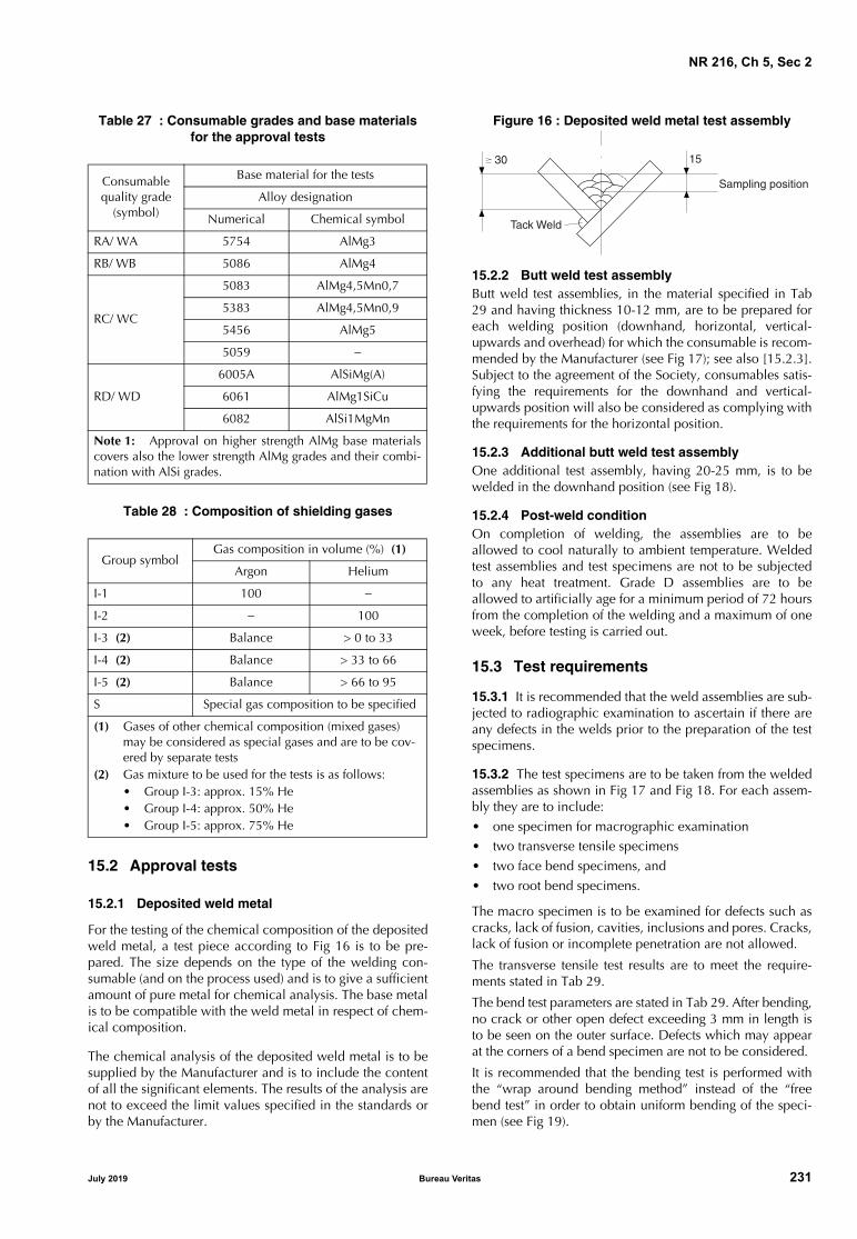
NR 216, Ch 5, Sec 2
Table 27 : Consumable grades and base materialsfor the approval tests
Table 28 : Composition of shielding gases
15.2 Approval tests
15.2.1 Deposited weld metal
For the testing of the chemical composition of the depositedweld metal, a test piece according to Fig 16 is to be pre-pared. The size depends on the type of the welding con-sumable (and on the process used) and is to give a sufficientamount of pure metal for chemical analysis. The base metalis to be compatible with the weld metal in respect of chem-ical composition.
The chemical analysis of the deposited weld metal is to besupplied by the Manufacturer and is to include the contentof all the significant elements. The results of the analysis arenot to exceed the limit values specified in the standards orby the Manufacturer.
Figure 16 : Deposited weld metal test assembly
15.2.2 Butt weld test assemblyButt weld test assemblies, in the material specified in Tab29 and having thickness 10-12 mm, are to be prepared foreach welding position (downhand, horizontal, vertical-upwards and overhead) for which the consumable is recom-mended by the Manufacturer (see Fig 17); see also [15.2.3].Subject to the agreement of the Society, consumables satis-fying the requirements for the downhand and vertical-upwards position will also be considered as complying withthe requirements for the horizontal position.
15.2.3 Additional butt weld test assemblyOne additional test assembly, having 20-25 mm, is to bewelded in the downhand position (see Fig 18).
15.2.4 Post-weld conditionOn completion of welding, the assemblies are to beallowed to cool naturally to ambient temperature. Weldedtest assemblies and test specimens are not to be subjectedto any heat treatment. Grade D assemblies are to beallowed to artificially age for a minimum period of 72 hoursfrom the completion of the welding and a maximum of oneweek, before testing is carried out.
15.3 Test requirements
15.3.1 It is recommended that the weld assemblies are sub-jected to radiographic examination to ascertain if there areany defects in the welds prior to the preparation of the testspecimens.
15.3.2 The test specimens are to be taken from the weldedassemblies as shown in Fig 17 and Fig 18. For each assem-bly they are to include: • one specimen for macrographic examination• two transverse tensile specimens• two face bend specimens, and• two root bend specimens.
The macro specimen is to be examined for defects such ascracks, lack of fusion, cavities, inclusions and pores. Cracks,lack of fusion or incomplete penetration are not allowed.
The transverse tensile test results are to meet the require-ments stated in Tab 29.
The bend test parameters are stated in Tab 29. After bending,no crack or other open defect exceeding 3 mm in length isto be seen on the outer surface. Defects which may appearat the corners of a bend specimen are not to be considered.
It is recommended that the bending test is performed withthe “wrap around bending method” instead of the “freebend test” in order to obtain uniform bending of the speci-men (see Fig 19).
Consumable quality grade
(symbol)
Base material for the tests
Alloy designation
Numerical Chemical symbol
RA/ WA 5754 AlMg3
RB/ WB 5086 AlMg4
RC/ WC
5083 AlMg4,5Mn0,7
5383 AlMg4,5Mn0,9
5456 AlMg5
5059 −
RD/ WD
6005A AlSiMg(A)
6061 AlMg1SiCu
6082 AlSi1MgMn
Note 1: Approval on higher strength AlMg base materialscovers also the lower strength AlMg grades and their combi-nation with AlSi grades.
Group symbolGas composition in volume (%) (1)
Argon Helium
I-1 100 −
I-2 − 100
I-3 (2) Balance > 0 to 33
I-4 (2) Balance > 33 to 66
I-5 (2) Balance > 66 to 95
S Special gas composition to be specified
(1) Gases of other chemical composition (mixed gases) may be considered as special gases and are to be cov-ered by separate tests
(2) Gas mixture to be used for the tests is as follows:• Group I-3: approx. 15% He• Group I-4: approx. 50% He• Group I-5: approx. 75% He
30 15
Tack Weld
Sampling position
July 2019 Bureau Veritas 231

NR 216, Ch 5, Sec 2
Figure 17 : Butt weld test assembly for positional welding
T = flat tensile test specimen; BC = face bend test specimen; BR = root bend test specimen; M = macrographic section
Note 1: Edge preparation is to be single V or double V with an angle of 70°.
Note 2: Back sealing runs are allowed in single V weld assemblies.
Note 3: In case of double V assembly, both sides are to be welded in the same welding positions.
Figure 18 : Additional butt weld test assembly in downhand position
T = flat tensile test specimen; BC = face bend test specimen; BR = root bend test specimen; M = macrographic section
Note 1: Edge preparation is to be single V with an angle of 70°.
Note 2: Back sealing runs are allowed.
BR
BC
T
M
BR
BC
T
10-12
350
35
30
350
20-25
350
T
BC
BR
35
30
M
BR
BC
T
350
232 Bureau Veritas July 2019

NR 216, Ch 5, Sec 2
Table 29 : Requirements for the transverse tensile and bend tests
Figure 19 : Wrap around bend test
The fixed edge of the test specimen is to be clamped to avoid sliding.The whole welded zone (weld and heat affected zone), in the case oftransverse bending, is to be entirely positioned in the bent zone.
15.4 Annual control tests
15.4.1 For the annual control tests, the deposited weld metal test assembly as per Fig 16 and the butt weld test assem-bly as per Fig 17 are to be welded.The tests required in [15.2.1] and [15.3] are to be per-formed.
GradeBase material
used for the testTensile strength Rm
(N/mm2) min.Former diameter
Bending angle (1)(°) min.
RA/ WA 5754 190 3 t
180
RB/ WB 5086 240 6 t
RC/ WC
5083 275 6 t
5383 or 5456 290 6 t
5059 330 6 t
RD/ WD 6061, 6005A or 6082 170 6 t
(1) During testing, the test specimen is not to reveal any one single flaw greater than 3 mm in any direction. Flaws appearing at thecorners of a test specimen is to be ignored in the evaluation unless there is evidence that they result from lack of fusion.
July 2019 Bureau Veritas 233

NR 216, Ch 5, Sec 3
SECTION 3 APPROVAL OF OVER WELDABLE SHOP PRIMERS
1 Scope
1.1 General
1.1.1 Shop primers applied on plates and sections to bewelded without being removed are to be approved by theSociety in accordance with the procedure detailed in thisSection.
1.1.2 The approval is limited to the following welding pro-cesses:
• manual metal arc welding with covered electrode
• flux-cored wire metal arc welding
• solid wire metal arc welding.
The acceptance of shop primers for use with welding pro-cesses other than those above will be specially consideredin connection with the approval of the welding procedureat the user’s works.
2 Information and documentation to be submitted
2.1 General
2.1.1 The application for approval is to be submitted to theSociety by the shop primer Manufacturer or authorised sup-plier.
2.1.2 The following information and supporting documen-tation, as applicable, are to be submitted:
• type designation, product name
• product description including components of theprimer, type of diluent and mixture ratio
• product specification, data sheet giving characteristicsof the shop primer and application instruction (surfacepreparation, method of application, drying time, recom-mended dry coat thicknesses, etc.)
• documentation relevant to previous tests and approvals.
• welding procedure specifications used
• approval test results (see [3]).
3 Approval tests
3.1 Base material
3.1.1 Normal strength hull steels or equivalent grades areto be used for the test samples.
3.2 Filler metal
3.2.1 Approved filler metals are to be used.
3.2.2 Basic covered electrodes are to be used for manualmetal arc welding.
3.3 Type and dimension of test samples
3.3.1 Test samples consist of double fillet welded T-jointsformed by plates of the following dimensions:
• 300 mm x 120 mm x 15 mm for manual welding andsemiautomatic bare wire and flux cored arc weldingwith gas shielding
3.4 Number of samples required
3.4.1 Two samples for each process are to be welded:
a) manual metal arc welding with covered electrode ofdiameter 4 mm
b) flux-cored wire metal arc welding with wire of diameter1,2 mm
c) solid wire metal arc welding with wire of diameter1,2 mm.
3.5 Preparation of test samples
3.5.1 The shop primer is to be applied in compliance withthe manufacturer’s specifications.
The shop primer thickness (measure made on dry coat) ofthe test samples is to be at least 30% greater than the maxi-mum foreseen in normal use.
3.5.2 The pieces are to be tack welded such as to form a Twith adherent contact between the surfaces, without gap.
For each test a), b) and c) described in [3.4.1], one sample isto be welded in horizontal-vertical position (PB), and theother in vertical upwards position (PF), using electrodes ofdiameter 4 mm and wire of diameter 1,2 mm. Welding is tobe made in accordance with Welding Procedure Specifica-tion (WPS).
The fillet weld is to be deposited in one bead having dimen-sions not exceeding 7 mm x 7 mm as shown in Fig 1.
234 Bureau Veritas July 2019

NR 216, Ch 5, Sec 3
Figure 1 : Typical T welded sample
A : Surfaces coated with the shop primerB : Weld bead
3.6 Test requirements
3.6.1 The test sample is to be fractured by suitable meansin order to locate the fracture in the throat of the fillet weld.
3.6.2 Visual examination is to be carried out consisting ofchecking the external and fractured surface to determineweld penetration and presence of worm-holes, pores andother defects.
Possible defects located within 10 mm from the ends of theweld are disregarded.
Lack of penetration having total length not exceeding 1/4 ofthe weld length is accepted.
Wormholes and pores having diameter not exceeding 3mmare generally acceptable where the total area of porosity isnot higher than 5% of the fracture section area.
3.7 Re-tests
3.7.1 Where tests on one sample fails, re-tests on two sam-ples for the same welding process are admitted.
Both test samples are to provide satisfactory results. Failingthis, the shop primer is not approved.
4 Certification and validity
4.1 Certification
4.1.1 Subject to the satisfactory outcome of the requiredchecks and tests, the Society will issue to the Manufactureror supplier concerned the approval certificate for the shopprimer.
4.2 Validity
4.2.1 The approval certificate has five-year validity. Foranother five-year period, renewal survey is to be carried outby the Society. The manufacturer has to declare that nochanges have been made to the production.
B
7 mm
A
A
July 2019 Bureau Veritas 235

NR 216, Ch 5, Sec 4
SECTION 4 APPROVAL OF WELDING PROCEDURES
1 General
1.1 Scope
1.1.1 GeneralThis Section specifies in Articles [2], [6], [7] and [8] therequirements for the approval of arc welding procedures forsteel materials, in Article [9] those for aluminium alloys andin Article [10] those for copper alloys.
The requirements relevant to materials not covered hereinare agreed on a case-by-case basis following, as far asapplicable, the criteria specified in this Section.
1.1.2 Other standards and specificationsProcedures considered equivalent by the Society may beaccepted.
1.1.3 Special requirementsIn the case of applications involving the storage and trans-port of liquefied gases, the appropriate requirements of theSociety’s Rules for the Classification of Steel Ships alsoapply.
1.2 Welding procedure
1.2.1 Welding processesQualification tests are, as a rule, required for the manual orsemiautomatic or automatic processes indicated belowtogether with their relevant numbering according to ISO4063:• Manual metal arc welding: 111 • Submerged Arc Welding with wire electrode (SAW): 12• Flux-Cored wire metal Arc Welding without gas shield
(FCAW): 114 • Metal arc Inert Gas welding (MIG welding): 131• Metal arc Active Gas welding (MAG welding): 135• Flux-Cored wire metal Arc Welding with active gas
shied: 136• Flux-Cored wire metal Arc Welding with inert gas
shield: 132• Tungsten Inert Gas arc welding (TIG welding): 141• Plasma Arc Welding (PAW): 15.
1.2.2 Welding consumables Consumables approved in accordance with the require-ments of Sec 2 are to be used within the limits of theirapproval.
When non-approved welding consumables are used, therequirements relevant to the qualification of the weldingprocedures are established on a case-by-case basis and testson a deposited metal sample are required.
Requirements relevant to the grade of welding consumablesto be used are given in the relevant Society’s Rules.
1.2.3 Preliminary welding procedure specification
A welding procedure specification is to be prepared by theManufacturer or Shipyard which intends to perform thequalification tests. This document is also referred to as apreliminary welding procedure specification (pWPS) and isto be submitted to the Society for review prior to the tests.
This pWPS may be modified and amended during the pro-cedure tests as deemed necessary however it shall define allrelevant variables as mentioned in the welding procedurespecification, see [1.2.4].
In case that the test pieces welded according to the pWPSshow unacceptable results the pWPS shall be adjusted bythe Shipyard or Manufacturer. The new pWPS shall be pre-pared and the test pieces welded in accordance with thenew pWPS.
In general, the qualification tests shall reflect fabricationconditions in respect to welding equipment, inside or out-side fabrication, weld preparation, preheating and any post-weld heat treatment. It shall be the manufacturer’s responsi-bility to establish and document whether a procedure issuitable for the particular application.
The test pieces are to be chosen so as to cover all the pro-duction welds in accordance with the approval range ofparameters given in [2.6], [9.5] and [10.3].
1.2.4 Approval of welding procedure specification
The qualification tests when required, welding of test piecesaccording to the proposed pWPS and testing of test speci-mens, are to be witnessed by the Surveyor.
Upon satisfactory completion of the tests, the Society mayapprove the pWPS as a welding procedure specification.
In its final version, the welding procedure specification(WPS) is to include all the parameters characterising thewelding process; in particular, as applicable:
a) type of welding process and equipment, as appropriate
b) type of joint, preparation and backing material, if any
c) base metal and thickness range
d) filler metal
e) welding position
f) minimum preheat, minimum and maximum interpasstemperature
g) post-weld heat treatment if applicable
h) shielding gas as applicable
i) welding parameters
j) other information relevant to the welding techniques asapplicable.
236 Bureau Veritas July 2019

NR 216, Ch 5, Sec 4
The actual parameters used for welding the approval testpieces and the results of the inspections and tests carriedout are to be recorded in the welding procedure qualifica-tion record (WPQR) also referred to as welding procedureapproval record (WPAR).
The WPQR is generally prepared by the shipyard or weldingshops and endorsed by the attending Surveyor.
1.2.5 Inspections
Inspections and control tests may be periodically and ran-domly required as deemed necessary by the Society and areto yield satisfactory results in order to maintain the validityof the approval.
The results of any suitable control performed during pro-duction may be accepted, to the Surveyor’s satisfaction.
1.2.6 Responsibilities of the users
The qualification tests are intended to verify that a manufac-turer is adequately qualified to perform welding operationsusing a particular procedure.
Irrespective of the inspections carried out by the Surveyor,the user is responsible for the use of the approved proce-dures, within the limits of the range qualified and the condi-tions stated at the time of the approval.
Compliance with the above is essential for the validity ofthe approval.
2 Welding procedure qualification tests for C and C-Mn steels for ship hull and other welded structures in general
2.1 Plates butt weld with full penetration
2.1.1 Assembly of test pieces
Preparation and welding are to be in accordance with thepWPS and under the general condition of production weld-ing which it represents.
If tack welds and / or start and stop points are a condition ofthe weld process they are to be fused into the joint and areto be included in the test pieces.
The test assembly is to be of a size sufficient to ensure a rea-sonable heat distribution and is to have the minimum fol-lowing dimensions (see Fig 1):
a) manual or semiautomatic welding:
length L = 6 t, minimum 350 mm
width W with W/2 = 3 t, minimum 150 mm.
b) automatic welding:
length L ≥ 1000 mm
width W with W/2 = 4 t, minimum 200 mm.
In the case of steel plates impact tested in the longitudinaldirection (CVN-L), the butt weld of the test piece is perpen-dicular to the rolling direction of the two plates.
In the case of steel plates impact tested in the transversaldirection (CVN-T), the butt weld of the test piece is parallelto the rolling direction of the two plates.
2.1.2 Examinations and tests
Non-destructive examinations and destructive tests requiredaccording to Tab 1 are to be carried out, while the locationof the test specimens is to be in accordance with Fig 2.
2.1.3 Non-destructive examinations
Non-destructive examinations are to be carried out afterany required or specified post-weld heat treatment andprior to the cutting of test specimens.
Imperfections detected by visual or non-destructive testingshall be assessed in accordance with ISO 5817 class B,except for the following imperfections for which the level Capplies:
• excess weld metal or convexity,
• excess throat thickness, and
• excess of penetration.
2.1.4 Transverse tensile tests
Specimens for transverse tensile tests are to be in accor-dance with Ch 1, Sec 2, [2.1.11].
The tensile strength recorded for each specimen is to be notless than the minimum required for the parent metal; thelocation of the fracture is to be reported.
When butt welds are made between plates of differentgrades, the tensile strength to be obtained on the weldedassembly is to be in accordance with the requirement of thegrade having lower strength.
Figure 1 : Test assembly for plate butt weld
����� �������� ��
��
��
��� ���
�
������ ��������� ������
������������� ��
���������������������
� ���
� ���
July 2019 Bureau Veritas 237

NR 216, Ch 5, Sec 4
Figure 2 : Location of test specimens
Weld
T1
P1
P2
Longitundinal tensile test
������ ��� � ���� � ������� � � ���� ������
P3
P4
Transverse tensile test
Face bend test
Root bend test
Face bend test
Root bend test
Discard
5050
Thi
ckne
ss
or 2 side bend test
M Macro examination & Hardness test
Discard
T2 Transverse tensile test
��� � � ����� ����
��� � � ����
or 2 side bend test
238 Bureau Veritas July 2019

NR 216, Ch 5, Sec 4
Table 1 : Examinations and tests
2.1.5 Tensile tests on cylindrical specimensWhen required (see Tab 1), a round tensile specimen is tobe cut along the weld axis to the dimension given in Ch 1,Sec 2, Fig 3, in the all weld metal.
Where the size of the deposited metal is too small, a 6 mmdiameter specimen may be taken or a deposited weld metaltest is to be carried out in accordance with the requirementsof Sec 2.
The tensile properties recorded (yield stress ReH, tensilestrength Rm and elongation A5) are to be not less than theminimum required for the approval of the appropriate gradeof consumables.
When more than one welding process or type of consum-able has been used to make the test weld, test specimensare to be removed from the area of the weld where eachwas used with the exception of those processes or consum-ables used to make the first weld run or root deposit.
2.1.6 Bend testsTransverse root bend, face bend and side bend specimensare to be machined to the dimensions given in Ch 1, Sec 2,[3.1].
For dissimilar or heterogeneous butt-joints, one longitudinalbend test may be used instead of transverse bend tests.
The test specimens are to be bent on a mandrel having adiameter equal to 4 times the thickness of the specimen; thebending angle is to be 180°.
After testing, the test specimens are not to reveal any opendefect, in any direction, greater than 3 mm. Defects appear-ing at the corners of the test specimen during testing are tobe investigated case-by-case.
When butt welds are made between plates of differentgrades, face and root longitudinal bend test specimens maybe used instead of the transverse bend test specimens.
2.1.7 Impact tests Dimensions and testing of Charpy V-notch impact test spec-imens are to be in accordance with Ch 1, Sec 2.
Charpy V-notch impact test specimens in accordance withCh 1, Sec 2 are to be sampled from 1 to 2 mm below thesurface of the parent material, transverse to the weld and onthe side containing the last run.
The Charpy V-notch specimens are located in the butt-weldedjoint as indicated in Fig 3, Fig 4, Fig 5 and Fig 6, and the V-notch is to be cut perpendicular to the surface of the weld.
The test temperature and absorbed energy are to be inaccordance with Tab 2.
When butt welds are made between different steel grades /types, the test specimens are to be taken from the side of thejoint with steel of lower toughness level. Temperature andabsorbed energy results are to be in accordance with the min-imum value required for the steel of lower toughness level.
Where more than one welding process or consumable hasbeen used to make the test weld, impact test specimens areto be removed from the respective areas where each wasemployed. This should not apply to the process or consum-ables used solely to make the first weld run or root deposit.
When cast or forged material with specified impact valuesis to be welded, test temperature and absorbed energy areto be in accordance with the requirements of the base mate-rial.
Unless otherwise agreed with the Society, the test tempera-ture and absorbed energy of steels not covered by theserequirements are to be in accordance with the specificationof the parent metal.
2.1.8 Macro examinationsThe test specimens are to be prepared and etched on oneside to clearly reveal the weld metal, fusion line, the heataffected zone (HAZ) and about 10mm of unaffected parentmetal.
The examination shall reveal a regular weld profile, throughfusion between adjacent layers of weld and base metal andthe absence of defects such as cracks, lack of fusion etc.
2.1.9 Hardness testsHardness testing is required for steels with minimum speci-fied yield strength equal to or greater than 355N/mm2.Unless otherwise agreed, the Vickers method HV10 is to beused.
The indentations are to be made in the weld, heat affectedzones, and the parent metals measuring and recording thehardness values. Two rows of indentations are to be carriedout in accordance with Fig 7.
For each row of indentations, there is to be a minimum of3 individual indentations in the weld, the heat affectedzones (both sides) and the parent metals (both sides).
The distance between the indentations may vary from 0,5 to2 mm depending on the zone tested.
Typical example of hardness indentations are given in Fig 7.
The results of hardness tests are not to exceed 350 HV forsteels with a specified minimum yield strength less than orequal to 420 N/mm2.
Type of examination or test Extent of examination or test
Visual examination 100%
Surface crack detection (1) 100%
Radiographic or ultrasonic examination
100%
Transverse tensile test 2 specimens
Transverse bend tests (2) 2 root and 2 face specimens
Charpy V-notch impact tests (3) 3 sets
Macro examination on 1 section
Hardness test (4) on 1 section
Longitudinal tensile test (5) 1 specimen
(1) Dye penetrant according to ISO 3452 (or equivalentaccepted standard) or magnetic particle testing; fornon-magnetic materials, dye penetrant only.
(2) For t ≥ 12 mm, the face and root bends are preferably tobe replaced by 4 side bends.
(3) 3 sets each of 3 specimens as per [2.1.7].(4) Only required for high strength steels with minimum
specified yield strength equal to or greater than355 N/mm2.
(5) Required only when the use of non-approved fillermetal has been accepted (see [1.2.2]).
July 2019 Bureau Veritas 239

NR 216, Ch 5, Sec 4
Table 2 : Impact test requirements for butt joints (t ≤ 50 mm)
Figure 3 : Location of V-notch for normal heat input ≤ 50 kJ/cm (t ≤ 50 mm)
Note 1: For one side pass welding over 20 mm, is to be added on root side 3KV with notch located on (a).
3KV with notch located on:
a : Centre of weld “WM”
b : On fusion line “FL”
c : In HAZ, 2 mm from fusion line
Figure 4 : Location of V-notch for normal heat input ≤ 50 kJ/cm (t > 50 mm)
3KV with notch located on:
a : Centre of weld “WM”
b : On fusion line “FL”
c : In HAZ, 2 mm from fusion line
Grade of steelTesting temperature
(°C)
Value of minimum average absorbed energy (J) (1)
For manually or semi-automatically welded jointsFor automatically
welded jointsDownhand, Horizontal, Overhead
Vertical upward,Vertical downward
A (2) 20
47
34 34
B (2), D 0
E −20
AH32, AH36 20
DH32, DH36 0
EH32, EH36 −20
FH32, FH36 −40
39 39
AH40 20
DH40 0
EH40 −20
FH40 −40
(1) For thickness above 50 mm, impact test requirements are to be agreed by the Society.(2) For grade A and grade B steels, average absorbed energy in fusion line and heat affected zone is to be minimum 27 J.
��� ����� ��
��� ��
� ���� ��
� �� � �� �� ���
��� �� ��� ��
��� ��
� ���� ��
� �
� � �� ��
�
�
240 Bureau Veritas July 2019

NR 216, Ch 5, Sec 4
Figure 5 : Location of V-notch for high heat input > 50 kJ/cm (t ≤ 50 mm)
Note 1: For one side pass welding over 20 mm, is to be added on root side 3KV with notch located on (a), (b) and (c).
3KV with notch located on:
a : Centre of weld “WM”
b : On fusion line “FL”
c : In HAZ, 2 mm from fusion line
d : In HAZ, 5 mm from fusion line
e : In HAZ, 10 mm from fusion line in case of heat input > 200 kJ/cm
Figure 6 : Location of V-notch for high heat input > 50 kJ/cm (t > 50 mm)
3KV with notch located on:
a : Centre of weld “WM”
b : On fusion line “FL”
c : In HAZ, 2 mm from fusion line
d : In HAZ, 5 mm from fusion line
e : In HAZ, 10 mm from fusion line in case of heat input > 200 kJ/cm
2.2 T butt joints in plates
2.2.1 General
Where this type of joints is predominant in production,qualification tests are to be performed on T butt joint assem-bly in addition to the equivalent qualification on butt joint.
The same principle applies when changes occur in thegeometry of the bevel which may significantly affect thepenetration or fusion.
2.2.2 Assembly and welding
Preparation and welding are to be in accordance with thepWPS and under the general condition of production weld-ing which it represents.
If tack welds are a condition of the weld process, they are tobe fused into the joint and are to be included in the testpieces.
The test assembly is to be of a size sufficient to ensure a rea-sonable heat distribution and is to have the minimum fol-lowing dimensions (reference can be made to Fig 9):
a) manual or semiautomatic welding:
length L = 6 t, min. 350 mm
width W = 3 t, min. 150 mm
b) automatic welding:
length L = min. 1000 mm
width W = 3 t, min. 150 mm.
��� ����� ��
��� ��
� ���� ��
� �
� � �� �� ���
� �
��� �� ��� ��
��� ��
� ���� ��
� �
� � �� ��
� �
� �
� �
July 2019 Bureau Veritas 241

NR 216, Ch 5, Sec 4
Figure 7 : Examples of hardness indentations
2.2.3 Examinations and tests
Non-destructive examinations and destructive tests arerequired according to Tab 3; a discard of 50 mm from bothedges is permitted.
2.2.4 Non-destructive examination
Reference is made to [2.1.3].
2.2.5 Tensile tests on cylindrical specimens
Reference is made to [2.1.5].
2.2.6 Macro examination
Reference is made to [2.1.8].
2.2.7 Hardness test
Hardness testing is required for steels with minimum speci-fied yield strength equal to or greater than 355 N/mm².Unless otherwise agreed, the Vickers method HV10 is to beused.
The indentations are to be made in the weld, heat affectedzones, and the parent metals measuring and recording thehardness values.
Rows of indentations are to be carried out in accordancewith Fig 8.
For each row of indentations, there is to be a minimum of 3individual indentations in the weld, the heat affected zones(both sides) and the parent metals (both sides).
The results of hardness tests are not to exceed 350 HV forsteels with a specified minimum yield strength less than orequal to 420 N/mm².
Table 3 : Examinations and tests for T butt joints in plates
2.3 Plates fillet weld
2.3.1 Assembly and welding
Preparation and welding are to be in accordance with thepWPS and under the general condition of production weld-ing which it represents.
If tack welds are a condition of the weld process they are tobe fused into the joint and are to be included in the testpieces.
The test assembly is welded on one side only. For singlepass manual and semi-automatic welding, a stop/restart isto be included in the test length and its position is to beclearly marked for subsequent examination.
The test assembly is to be of a size sufficient to ensure a rea-sonable heat distribution and is to have the minimum fol-lowing dimensions (see Fig 9):
a) manual or semiautomatic welding:
length L = 6 t, minimum 350 mm
width W = 3 t, minimum 150 mm
b) automatic welding:
length L ≥ 1000 mm
width W = 3 t, minimum 150 mm.
2.3.2 Examinations and tests
Non-destructive examinations and destructive tests requiredaccording to Tab 4; a discard of 50 mm from both edges ispermitted.
2 m
mm
ax
2 m
mm
ax2
mm
max
2 m
mm
ax
2 m
mm
ax
t ≤ 5 mm
t
t
t > 5 mm
Parent metal Parent metal
HAZ narrow HAZ wide
Weld
Type of examination or test Extent of examination or test
Visual examination 100%
Surface crack detection (1) 100%
Ultrasonic examination (4) 100%
Macro examination on 1 section
Hardness test (2) on 1 section
Longitudinal tensile test (3) 1 specimen
(1) Dye penetrant according to ISO 3452 (or equivalentaccepted standard) or magnetic particle testing; fornon-magnetic materials, dye penetrant only.
(2) Only required for high strength steels with minimumspecified yield strength equal to or greater than355 N/mm².
(3) Required for thickness above 50 mm or when the use ofnon-approved filler metal has been accepted (see [1.2.2]).
(4) Applicable to full penetration weld or to verify theextent of penetration in partial penetration welds
242 Bureau Veritas July 2019

NR 216, Ch 5, Sec 4
Figure 8 : Hardness indentations
with H, dimension in mm.
Figure 9 : T fillet joint on plates
2.3.3 Visual examination and surface crack detection
Non-destructive examinations are to be carried out afterany required or specified post-weld heat treatment andprior to the cutting of test specimens.
Imperfections detected are to be assessed in accordancewith [2.1.3].
Table 4 : Examinations and tests
2.3.4 Macro examination
The test specimen is to be prepared and etched on one sideto clearly reveal the weld metal, fusion line, root penetra-tion, the heat affected zone and about 10mm of unaffectedbase material.
The examination shall reveal a regular weld profile, throughfusion between adjacent layers of weld and base metal andthe absence of defects such as cracks, lack of fusion etc.
The dimensions of leg size, throat and penetration are to bereported.
� �
� ≤ ���
� �
� ≤ ���
�≤ �
� ≤ �
�≤ ���
� ≤ �
�≤ ���
��
��
��
��
�≤ �
��� ����� ���
Weld one side or bothsides and fit-up as detailedin the preliminary WeldingProcedure Specification
t1
t2
W
W
L
W
Type of examination or test Extent of examination or test
Visual examination 100%
Surface crack detection (1) 100%
Macro examination (2) 2 sections
Hardness test (3) on 1section
Fracture test 1 test
(1) Dye penetrant according to ISO 3452 (or equivalentaccepted standard) or magnetic particle testing; fornon-magnetic materials, dye penetrant only.
(2) One of the macro sections is to be taken at the positionof the stop/restart; see [2.3.1].
(3) Only required for high strength steels having:ReH ≥ 355 N/mm2
July 2019 Bureau Veritas 243

NR 216, Ch 5, Sec 4
2.3.5 Fracture test
The fracture test is to be performed by folding the uprightplate onto the through plate. Evaluation is to be concen-trated on cracks, porosity and pores, inclusions, lack offusion and incomplete penetration. Imperfections that aredetected shall be assessed in accordance with ISO 5817Class B.
2.3.6 Hardness test
Hardness testing is required for steels with minimum speci-fied yield strength equal to or greater than 355N/mm2.Unless otherwise agreed, the Vickers method HV10 is to beused.
The indentations are to be made in the weld, heat affectedzones, and the parent metals measuring and recording thehardness values. Two rows of indentations are to be carriedout in accordance with Fig 10.
For each row of indentations, there is to be a minimum of 3individual indentations in the weld, the heat affected zones(both sides) and the parent metals (both sides).
The results of hardness tests are not to exceed 350 HV forsteels with a specified minimum yield strength less than orequal to 420 N/mm2.
2.4 Pipes butt weld with full penetration
2.4.1 Assembly and welding
Preparation and welding are to be in accordance with thepWPS and under the general condition of production weld-ing which it represents.
If tack welds are a condition of the weld process they are to befused into the joint and are to be included in the test pieces.
The test assembly is to be in accordance with Fig 11.
2.4.2 Examinations and tests
Non-destructive examinations and destructive tests requiredaccording to Tab 1. The location of the test specimens is tobe in accordance with Fig 12.
2.4.3 ResultsThe results are to comply with the requirements for platebutt weld in [2.1].
Figure 10 : Macro and hardness indentations
Figure 11 : Pipe weld test assembly
W = 150 mm minimum; D = outside diameter
Figure 12 : Location of test specimens
� ≤ �
� ≤ ����
�≤ �
�≤ �
�≤ ���
�
�≤ �
� �
� �
��
Edge preparation and fit-up as detailedin the preliminary Welding Procedure Specification
W W
D
Area A for :
- 1 macro test specimen,- 1 tensile specimen,- 1 root and 1 face or 2 side bend specimens.
Area B for :
- impact and longitudinal tensile test specimens if required
Area C for :
- 1 tensile specimen,- 1 root and 1 face or 2 side bend specimens.
Area D for :
- 1 macro test specimen,- 1 hardness test specimen.
Top for fixed pipe
244 Bureau Veritas July 2019

NR 216, Ch 5, Sec 4
2.5 Re-testing
2.5.1 If the test piece fails to comply with any of therequirements for visual or non-destructive testing, one fur-ther test piece is to be welded and subjected to the sameexamination.
If this additional test piece does not comply with the rele-vant requirements, the pWPS is to be regarded as not capa-ble of complying with the requirements withoutmodification.
2.5.2 If any test specimens fails to comply with the relevantrequirements for destructive testing due to weld imperfec-tion only, two further test specimens shall be obtained foreach one that failed. These specimens can be taken fromthe same test piece if there is sufficient material available orfrom a new test piece, and is to be subjected to the sametest. If either of these additional test specimens does notcomply with the relevant requirements, the pWPS is to beregarded as not capable of complying with the require-ments without modification.
2.5.3 If a tensile test specimen fails to meet the require-ments, the re-testing is to be in accordance with Ch 1, Sec2, [2.3].
2.5.4 If there is a single hardness value above the maxi-mum values allowed, additional hardness tests shall be car-ried out (on the reverse of the specimen or after sufficientgrinding of the tested surface). None of the additional hard-ness values is to exceed the maximum hardness valuesrequired.
2.5.5 The re-testing of Charpy V-notch impact test speci-mens are to be carried out in accordance with Ch 1, Sec 2,[4.4].
2.5.6 Where there is not sufficient material remaining inthe test piece to provide the additional test specimens, a fur-ther assembly shall be welded using the same procedure toprovide the additional specimens.
2.6 Range of approval
2.6.1 General
The approval of a WPS obtained by a yard or Manufactureris valid for welding in workshops under the same technicaland quality management, to the Society’s satisfaction.
The welding procedure is to be used within the range of theparameters indicated below; changes outside the rangespecified of one or more of these parameters require a newqualification test.
2.6.2 Parent metal
For hull structural steel grades A to FH40 as defined in Ch2, Sec 1, [2], the following applies:
a) For each strength level, welding procedures are consid-ered applicable to the same and lower toughness gradesas that tested;
b) For each toughness grade, welding procedures are con-sidered applicable to the same and two lower strengthlevels as that tested;
c) For applying the above a) and b) to high heat input pro-cesses above 50kJ/cm, e.g. the two-run technique witheither submerged arc or gas shielded metal arc welding,electroslag and electrogas welding, welding procedureis applicable that toughness grade tested and onestrength level below.
Where steels used for construction are supplied from differ-ent delivery conditions from those tested, the Society mayrequire additional tests.
For weldable C and C-Mn hull steel forgings as defined inCh 2, Sec 3, [2], the following applies:
a) Welding procedures are considered applicable to thesame and lower strength level as that tested;
b) Qualification tests on quenched and tempered hullstructural steel forgings do not qualify other deliverycondition and vice-versa.
For weldable C and C-Mn hull steel castings as defined inCh 2, Sec 4, [2], the following applies:
a) Welding procedures are considered applicable to thesame and lower strength level as that tested;
b) Qualification tests on quenched and tempered hullstructural steel castings do not qualify other deliverycondition and vice-versa.
2.6.3 Thickness
The qualification of a WPS carried out on a welded assemblyof thickness t is valid for the thickness range given in Tab 5.
In addition to the requirements of Tab 5, the range ofapproval for fillet welds shall be as follows:
a) Single pass fillet welds; for throat thickness a, the rangeof approval is “0,75 a” to “1,5 a”
b) Multipass fillet welds; for throat thickness a, the range ofapproval is as for multipass butt welds (i.e. a = t).
For the vertical-down welding, the test piece thickness t isalways taken as the upper limit of the range of application.
For unequal plate thickness of butt welds the lesser thick-ness is the ruling dimension.
Notwithstanding the above, the approval of maximum basematerial thickness for any technique is restricted to the testassembly thickness if three of the hardness values in theheat affected zone are found to be within 25 HV of themaximum permitted, as stated in [2.1.9], in [2.2.7] and[2.3.6].
July 2019 Bureau Veritas 245

NR 216, Ch 5, Sec 4
Table 5 : Approved thickness range
2.6.4 Pipe diameter
Qualification tests on an assembly of pipes of diameter D isvalid for diameters in the range given in Tab 6.
Table 6 : Approved diameter range
2.6.5 Welding position
Standard positions are given in Fig 13 for plates and pipes.
Approval for a test made in any position is restricted to thatposition.
To qualify all positions, test assemblies are to be welded forhighest and lowest heat input position and all applicabletests are to be made on those assemblies.
For plates butt welds with full penetration, the highest heatinput position is normally the vertical upwards position andthe lowest heat input position is normally the horizontalposition.
2.6.6 Welding process
The approval is only valid for the welding process(es) usedin the qualification tests. It is not permitted to change from amulti-run to a single run.
For multi-process procedures the welding procedureapproval may be carried out with separate qualification testsfor each welding process. It is also accepted to make thequalification test as a multi-process procedure test. Theapproval of such a test is only valid for the process sequencecarried out during the multi-process procedure test.
For the manual metal arc welding process (111) and semi-automatic welding process with flux cored wire withoutshielding gas (114), the approval obtained is valid for thediameter of the electrode used in the welding proceduretest plus or minus one electrode diameter size for each run,except for the root run of the one side welded assemblywithout backing strip, for which no size change is allowed.
For the gas metal arc welding processes (131, 135, 136), theapproval obtained for face and/or back shielding gas isrestricted to the type of gas (nominal composition) usedduring the procedure test. The approval is restricted to thewire system used in the approval test (e.g. single wire ormulti-wire) and, in the case of automatic welding, to the rel-evant welding technique.
For the submerged arc processes (12), the approvalobtained is restricted to the wire system used in theapproval test (e.g. single wire or multi-wire) and relevantwelding technique (T, M, U). Change in the flux trade markrequires new welding procedure approval tests.
2.6.7 Welding consumables
Except high heat input process (over 50KJ/cm), weldingconsumables tested cover other approved welding consum-ables having the same grade mark including all suffixesspecified in Sec 2 with that tested.
Change in the trade name of filler metal requires new weld-ing procedure approval tests when Charpy V-notch impacttests are required at temperature strictly below −20°C.
2.6.8 Heat input
The upper limit of heat input approved is 25% greater thanthat used in welding the test piece or 50 kJ/cm whichever issmaller, except that the upper limit is 10% greater than thatfor high heat input processes over 50 kJ/cm.
The lower limit of heat input approved is 25% lower thanthat used in welding the test piece.
2.6.9 Preheat and interpass temperature
The minimum preheat temperature is not to be less than thatused in the qualification test.
The minimum interpass temperature is not to be less thanthe specified preheat temperature.
The maximum interpass temperature is not to be higherthan that used in the qualification test.
2.6.10 Post-weld heat treatment
The heat treatment used in the qualification test is to bemaintained during manufacture. Holding time may beadjusted as a function of thickness.
2.6.11 Type of joint
The range of approval depending on type of welded jointfor test assembly is given in Tab 7.
New qualification tests may be required by the Surveyorwhen changes occur in the geometry of the bevel whichmay significantly affect the penetration or fusion.
Thickness tof test piece
(mm) (1)
Range of approval
Butt and T-joint welds with single run or single run from both sides
Butt and T-joint welds with multi-run
andfillet welds (2)
3 < t ≤ 12 0,7 t to 1,1 t 3 mm to 2 t
12 < t ≤ 100 0,7 t to 1,1 t (3) 0,5 t to 2 t (max.150)
(1) For multi process procedures, the recorded thicknesscontribution of each process is to be used as a basis forthe range of approval for the individual welding pro-cess.
(2) For fillet welds, the range of approval is to be applied toboth parent materials.
(3) For high heat input process over 50 kJ/cm, the upperlimit of range of approval is to be 1,0 t.
Diameter of the test piece (mm) Range of approval (1)
D ≤ 25 0,5 D to 2 D
D > 25 ≥ 0,5 D (25 mm min.)
(1) Qualification for plates also covers pipes with outsidediameter > 500 mm.
246 Bureau Veritas July 2019

NR 216, Ch 5, Sec 4
Figure 13 : Welding positions according to ISO Standard
PB Horizontal Vertical
PA Flat
PG Vertical (downwards)
PE Overhead
PC Horizontal
PF Vertical (upwards)
PA Flat
PD Horizontal Overhead
PG Vertical (downwards) PF Vertical (upwards)
a) Butt welds for plates
b) Fillet welds for plates
45
Pipe : rotatingPA Axis : horizontal Welding : flat
c) Pipes butt weld
Pipe : fixedPF Axis : horizontal Welding : vertical upwards
Pipe : fixedPC Axis : vertical Welding : horizontal
Pipe : fixedHL045 Axis : inclined Welding : inclined upward
Pipe : fixedPG Axis : horizontal Welding : vertical downwards
July 2019 Bureau Veritas 247

NR 216, Ch 5, Sec 4
Table 7 : Range of approval for type of joint
3 Welding procedures for offshore structures and equipment
3.1 General
3.1.1 The applicable requirements are given in Rule NoteNR426 Construction Survey of Steel Structures of OffshoreUnits and Installations, as amended.
4 Welding procedures for cargo tanks and process pressure vessels of liquefied gas carriers
4.1 General
4.1.1 Reference is made to the requirements specified in[2.1] to [2.6] as far as applicable taking into account thatthe requirements of the International Code for the Construc-tion and Equipment of Ships Carrying Liquefied Gases inBulk (IGC Code) are to be applied.
5 Welding procedures for fuel tanks and process pressure vessels of gas fuelled ships
5.1 General
5.1.1 Reference is made to the requirements specified in[2.1] to [2.6] as far as applicable taking into account thatthe requirements of the International Code of Safety for
Ships using Gases or other Low-flash point Fuels (IGF Code)are to be applied.
6 Welding procedures for Cr-Ni austenitic and austenitic-ferritic stainless steels for application with chemicals
6.1 General
6.1.1 Test pieces, tests and requirements for the approval ofthe welding procedures are agreed on a case-by-case basisand are as far as applicable in accordance with those speci-fied in [2.1] to [2.6].
6.1.2 Checks of the chemical composition of the weldmetal may be required and, in the case of austenitic-ferriticsteels, the examination of the metallographic structure ofthe weld for the determination of the average ferrite contentis generally to be performed (value required according toASTM E 562: min. 25% and max. 65%).
Impact tests are not required in the case of austenitic steelsand are required in the case of austenitic-ferritic steels andperformed at −20°C; the average value for the absorbedenergy is to be not lower than 27 J.
Conventional corrosion tests according to recognised stan-dards may be required depending on the type of steel.
6.1.3 Typical selection of consumables grades dependingon the parent metal to be welded is given in Tab 8.
Type of welded joint
for test assembly
Range of approval
Butt welds and T butt joints for plates with full or partial penetration
Fillet welds on plate and pipe
Welded from one side Welded from both sides
with backing
no backing
with gouging
no gouging
Full penetration butt weld for plates
One side (1)
with backing − x − x
no backing x x x x
Both sideswith gouging − − − x
no gouging − − x x
Fillet weld for plates
− − − − − −
Note 1: indicates the type of assembly of qualification test.x indicates on the same line as the symbol those welds for which the WPS is also approved. − indicates on the same line as the symbol those welds for which the WPS is not approved.(1) Butt welds on a plate welded from one side approve butt welds on pipes having diameter > 500 mm within the limitations of
the Table.
248 Bureau Veritas July 2019

NR 216, Ch 5, Sec 4
Table 8 : Typical selection of consumable grades for welding Cr-Ni austenitic steels
7 Welding procedures for extra high strength steels
7.1 General
7.1.1 Test pieces, tests and requirements for the approval ofthe welding procedures are to be as specified in [2.1] to[2.6], unless otherwise specified in this Article.
7.1.2 The bend specimens are to be bent on a mandrel hav-ing a diameter equal to 5 times the specimen thickness inthe case of steel types 420 and 460 and equal to 6 times thespecimen thickness in the case of steel types 500, 550, 620and 690.
7.1.3 The results from the hardness test is not to exceed420 HV10 for steels with a specified minimum yieldstrength from 420 N/mm2 to 690 N/mm2.
7.1.4 For the range of approval of parent metal the follow-ing applies:
a) for each strength level, welding procedures are consid-ered applicable to the same and lower toughness gradesas that tested
b) for each toughness grade, welding procedures are con-sidered applicable to the same and one lower strengthlevels as that tested
c) qualification tests with quenched and tempered steelsdo not qualify thermo-mechanically rolled steels andvice-versa.
8 Approval of welding procedures for crack arrest steel EH47CAS
8.1 General
8.1.1 Test pieces, tests and requirements for approval of thewelding procedures are specified in [2.1] to [2.6], unlessotherwise specified in this Article.
8.1.2 Parent metalThe welding procedure is qualified for the parent metaltested.
8.1.3 Impact testsThe test temperature and absorbed energy are to be inaccordance with Tab 9.
8.1.4 Hardness testsAn additional row of indentations is to be carried out atmid-thickness.
The results of hardness tests are not to exceed 380 HV forcrack arrest steels with a specified minimum yield strengthequal to or greater than 460 N/mm2.
Table 9 : Impact test requirements for butt joints (t ≤ 100mm)
Consumable grade Steel grade to be welded
308 304
308L 304 - 304L
316 304 - 316
316L 304 - 304L - 316 - 316L
316LN 304 - 304L - 316 - 316L - 316LN - 316Ti - 316Nb
317 304 - 316 - 317
317L 304 - 304L - 316 - 316L - 317 - 317L
309 309 (1)
309L 309 - 309L (1)
309 Mo 309 - 309Mo - 316 (1)
310 310 (1)
310Mo 310 - 310Mo (1)
347 321- 347
(1) Also for joints between ferritic and austenitic steels.
Grade of steelTesting temperature
(°C)
Value of minimum average absorbed energy (J)
For manually or semi-automatically welded jointsFor automatically
welded jointsDownhand, Horizontal, Overhead
Vertical upward,Vertical downward
EH47CAS −20 64
July 2019 Bureau Veritas 249

NR 216, Ch 5, Sec 4
8.1.5 Brittle fracture initiation test
Deep notch test or CTOD test may be required for parentmetals. Tests are to be in accordance with recognised stan-dards acceptable to the Society.
9 Approval of welding procedures for aluminium alloys
9.1 Plates butt weld
9.1.1 Assembly and welding
The applicable requirements of [2.1.1] apply.
The cleaning of the parts to be welded is to be carried out inaccordance with the same procedure as used in the con-struction.
Welding consumables used are to be approved by the Soci-ety in accordance with Sec 2, [15].
9.1.2 Examinations and tests
Non-destructive examinations and destructive tests requiredaccording to Tab 10. The location of the test specimens is tobe in accordance with Fig 14.
Table 10 : Examinations and tests
9.1.3 Non-destructive examinations
Non-destructive examinations should be carried out afterany required post-weld heat treatment and natural or artifi-cial ageing, and prior to the cutting of test specimens.
Welds should be free from cracks. Imperfections detectedby visual or non-destructive testing should be assessed inaccordance with ISO 10042, level B, except for excess weldmetal or convexity, excess throat thickness and excess ofpenetration for which the level C applies.
Figure 14 : Location of test specimens for a butt joint in plate
9.1.4 Transverse tensile testsSpecimens for transverse tensile tests are to be in accor-dance with Ch 1, Sec 2, [2.1.11].
The weld is to be made flush maintaining the thickness ofthe assembly.
The tensile strength results are to meet the requirementsstated in Tab 11.
Table 11 : Minimum tensile strengthfor series 5000 and 6000 alloys
9.1.5 Bend testsTransverse root bend, face bend and side bend specimens areto machined to the dimensions given in Ch 1, Sec 2, [3.1].
For dissimilar or heterogeneous butt joints, longitudinalbend test may be used instead of transverse bend tests.
The bend test specimens should be bent on a mandrel withmaximum diameter as given in the formula below. Thebending angle shall be 180°.
where:
d : Maximum former diameterts : Thickness of the bend test specimen (this
includes side bends)
Type of examination or test Extent of examination or test
Visual examination 100%
Radiographic or ultrasonic examination
100%
Dye penetrant test 100%
Transverse tensile tests 2 specimens
Transverse bend tests (1) 2 root and 2 face specimens
Macro examination 1 section
Check of Mg content (2) weld metal
(1) The face and root bends are preferably to be replacedby 4 side bends for t ≥ 12 mm.
(2) In the case of non-approved filler metal, the check ofMg content and other checks, as appropriate, are gen-erally required.
Grade (Alloy designation)
Minimum tensile strength Rm (N/mm2)
5754 190
5086 240
5083 275
5383 290
5059 330
5456 290
6005 A 170
6061 170
6082 170
Discard 25 mm
Additional test specimensif required
1 tensile test specimen and2 bend test specimens
1 tensile test specimen and2 bend test specimens
Discard 25 mm
1 macro test specimen
d100 ts×( )
A------------------------ ts–=
250 Bureau Veritas July 2019

NR 216, Ch 5, Sec 4
A : Minimum tensile elongation required by thealloy grade, temper condition and thickness (forcombination between different alloys, the low-est individual value should be used).
The “wrap around bending method“ is the recommendedbending procedure in lieu of the usual “free” bend test (seeFig 15.
After testing, the test specimens are not to reveal any opendefect in any direction greater than 3 mm. Defects appear-ing at the corner of the test specimen may be disregardedunless there is evidence that they result from lack of fusion.
Figure 15 : Wrap around bend test
The fixed edge of the test specimen is to be clamped to avoid slid-ing. The whole welded zone (weld and heat affected zone), in thecase of transverse bending, is to be entirely positioned in the bentzone.
9.1.6 Macro examinationThe test specimens are to be prepared and etched on oneside to clearly reveal the fusion line, the HAZ, the build upof the runs and the unaffected parent metal. The examina-tion is to reveal a regular weld profile, through fusionbetween adjacent layers of weld and base metal, and theabsence of defects such as cracks and lack of fusion.
The acceptance levels are given in [9.1.3].
9.2 Plates fillet weld
9.2.1 Assembly and welding The requirements of [2.3.1] apply except otherwise speci-fied in the following.
The cleaning of the parts to be welded is to be carried out inaccordance with the same procedure as used in the con-struction.
The two plates are to be positioned and tack welded edge-wise so as to constitute a T assembly without clearance.
Welding on one or both sides and fit up are to be asdetailed in the pWPS.
In general for semi-automatic welding a stop/restart positionis to be included in the test length and is to be clearlymarked for subsequent examination.
9.2.2 Examinations and testsNon-destructive examinations and destructive tests are to becarried out in accordance with the requirements of Tab 12.
Table 12 : Examinations and tests
9.2.3 Visual examination and surface crack detection
The requirements specified in [9.1.3] are to be compliedwith.
9.2.4 Macro examination and fracture test The fracture test as well as the macro examination are toshow, in general, the absence of defects, in particular lackof root penetration.
However in the macro examination, small soundnessdefects of the weld metal such as blowholes or inclusionsmay be accepted provided that their total area does notexceed 6% of the weld metal section examined.
The dimensions of leg size, throat and penetration are gen-erally to be reported.
9.3 Pipes butt weld with full penetration
9.3.1 Assembly and weldingThe applicable requirements of [2.4.1] apply.
The cleaning of the parts to be welded is to be carried out inaccordance with the same procedure as used in the con-struction.
If the tack welds are a condition of the weld process theyare to be fused into the joint and are to be included in thetest pieces.
9.3.2 Examinations and testsNon-destructive examinations and destructive tests requiredaccording to Tab 10. The location of the test specimens is tobe in accordance with Fig 16.
9.3.3 ResultsThe results are to comply with the requirements for platesbutt weld in [9.1].
9.4 Re-testing
9.4.1 If the test piece fails to comply with any of therequirements for visual or non-destructive testing, one fur-ther test piece is to be welded and subjected to the sameexamination.
If this additional test piece does not comply with the relevantrequirements, the pWPS is to be regarded as not capable ofcomplying with the requirements without modification.
D = 6 - 7t
t
Roller
t + 2
B = 1/2 D + t
D
Type of examination or test Extent of examination or test
Visual examination 100%
Dye penetrant test 100%
Macro examination (1) 2 specimens
Fracture test 1 specimen
(1) One of the macro sections is to be taken at the positionof the stop/restart (see [9.2.1]).
July 2019 Bureau Veritas 251

NR 216, Ch 5, Sec 4
Figure 16 : Location of test specimens
9.4.2 If any test specimens fails to comply with the relevantrequirements for destructive testing due to weld imperfec-tion only, two further test specimens shall be obtained foreach one that failed. These specimens can be taken fromthe same test piece if there is sufficient material available orfrom a new test piece, and is to be subjected to the sametest. If either of these additional test specimens does notcomply with the relevant requirements, the pWPS is to beregarded as not capable of complying with the require-ments without modification.
9.4.3 If a tensile test specimen fails to meet the require-ments, the re-testing is to be in accordance with Ch 1, Sec2, [2.3].
9.5 Range of approval
9.5.1 General
Unless otherwise specified in this Article, reference may bemade to the requirements in [2.6].
9.5.2 Parent metal
The alloys are grouped into three groups:
a) Group A: Aluminium-magnesium alloys with Mg con-tent ≤ 3,5% (alloy 5754)
b) Group B: Aluminium-magnesium alloys with 4% ≤ Mg≤ 5,6% (alloys 5059, 5083, 5086, 5383 and 5456)
c) Group C: Aluminium-magnesium-silicon alloys (alloys6005A, 6061 and 6082).
For each group, qualification tests made on one alloy qual-ify the procedure for the other alloys of the same group withequal or lower minimum specified tensile strength afterwelding.
Qualification on Group B alloys qualify the procedure forGroup A alloys.
9.5.3 Thickness
The qualification of a WPS carried out on a test assembly ofthickness t is valid for the thickness range given in Tab 13.
In case of butt-joints between dissimilar thickness, t is thethickness of the thinner metal
In case of fillet joints between dissimilar thickness, t is thethickness of the thicker metal.
In addition to the requirements of Tab 13 the range of qualifi-cation of the fillet welds throat thickness a is given in Tab 14.
Where a fillet weld is qualified by means of a butt weld test,the throat thickness range qualified should be based on thethickness of the deposited weld metal.
Where the majority of production work is fillet welding, anadditional fillet weld test may be required.
9.5.4 Pipe diameter
Qualification tests on an assembly of pipes of diameter D isvalid for diameters in the range given in Tab 6.
Table 13 : Range of qualification for parent material thickness
Table 14 : Range of qualification for the throat thickness of fillet welds
Area A for :- 1 tensile specimen,- 1 root and 1 face or 2 side bend specimens
Area B for :- additional test specimens if required
Area C for :- 1 tensile specimen,- 1 root and 1 face or 2 side bend specimens.
Area D for :- 1 macro test specimen
Top for fixed pipe
Thickness t of the test piece (mm)
Range of qualifications
t ≤ 3 0,5 to 2 t
3 < t ≤ 20 3 to 2 t
t > 20 ≥ 0,8 t
Throat thickness a of the test piece (mm)
Range of qualifications
a < 10 0,75 a to 1,5 a
a ≥ 10 ≥ 7,5
252 Bureau Veritas July 2019

NR 216, Ch 5, Sec 4
9.5.5 Welding positions
The test pieces are to be welded in the position(s) used inthe construction taking into account that:
a) Horizontal-vertical position qualifies also for flat andvertical upwards positions
b) Vertical upwards position qualifies also for flat and hori-zontal-vertical positions
c) Overhead position qualifies also for flat, verticalupwards and horizontal-vertical positions.
9.5.6 Welding process
The approval is valid only for the welding process used inthe welding procedure test. It is not permitted to change amulti-run deposit into a single run (or run on each side) orvice versa for a given process. In the case of a multi-processprocedure, the approval is only valid for applying the pro-cesses in the order used during the procedure qualificationtests.
Note 1: For multi-process procedures each welding process may beapproved separately or in combination with other processes. Simi-larly one or more processes may be deleted from an approved WPSprovided the joint thickness is within the approved thickness rangeof the relevant welding process to be applied.
9.5.7 Welding consumables
The welding consumable used in the qualification testsqualifies:
a) Approved welding consumables of the same strength asthe consumable used in the procedure qualificationtests.
b) Approved welding consumables of higher strength thanthe consumable used in the procedure qualificationtests.
The qualification given to shielding gas and backing gas isrestricted to the gas/gas mixture used in the welding proce-dure test, see ISO 14175 or other recognised standards forgas designations.
9.5.8 Type of currentChanges in the type of current (AC, DC, pulsed) and polar-ity require a new welding procedure qualification.
9.5.9 Post-weld heat treatment or ageingAddition or deletion of post-weld heat treatment or ageingis not permitted. Artificial ageing for 6000 series alloys givesapproval for prolonged natural ageing.
9.5.10 Type of jointThe range of approval for the types of joint in relation to thetype of joint used in the procedure qualification test is givenin Tab 15.
10 Approval of welding procedures for copper alloys
10.1 Pipes butt weld
10.1.1 Assembly and weldingThe applicable requirements of [2.4.1] apply.
The cleaning of the parts to be welded is to be carried out inaccordance with the same procedure as used in the con-struction.
10.1.2 Examinations and testsNon-destructive examinations and destructive tests requiredaccording to Tab 16. The location of the test specimens is tobe in accordance with Fig 16.
10.1.3 Non-destructive examinationsReference is made to [9.1.3].
10.1.4 Transverse tensile testsReference is made to [2.1.4].
10.1.5 Bend testsReference is made to [9.1.5].
10.1.6 Macro examinationsReference is made to [9.1.6].
Table 15 : Range of approval for type of joint
Type of welded joint
for test assembly
Range of approval
Butt welds for plates with full or partial penetrationFillet welds on plate and pipe
Welded from one side Welded from both sides
with backing no backing with gouging no gouging
Butt joint welded
One side (1)
with backing − x − x
no backing x x x x
Both sideswith gouging − − − x
no gouging x − x x
Fillet weld for plates
− − − − − −
Note 1: indicates the type of assembly of qualification test.x indicates on the same line as the symbol those welds for which the WPS is also approved. − indicates on the same line as the symbol those welds for which the WPS is not approved.(1) Butt welds on a plate welded from one side approve butt welds on pipes having diameter > 500 mm within the limitations of
the Table.
July 2019 Bureau Veritas 253

NR 216, Ch 5, Sec 4
Table 16 : Examinations and tests
10.2 Re-testing
10.2.1 Reference is made to [9.4].
10.3 Range of approval
10.3.1 GeneralUnless otherwise specified in this Article, reference may bemade to the applicable requirement in [2.6].
10.3.2 Parent metalThe welding procedure is qualified for the parent metaltested. A change of parent metal may be considered basedon the range of approval of a recognised standard accept-able to the Society (e.g. ISO 15614-6).
10.3.3 Thickness
The qualification of a WPS carried out on a test assembly ofthickness t is valid for the thickness range given in the rele-vant parts of [9.5.3].
10.3.4 Pipe diameter
Reference is made to [2.6.4].
10.3.5 Welding process
For Tungsten Inert Gas arc welding (141) and Plasma ArcWelding (15), the approval obtained is restricted to the typeof gas used during the procedure test.
For Oxyacetylene welding (311), the approval obtainedwith filler metal does not qualify welding without fillermetal and vice-versa.
10.3.6 Welding consumables
Welding consumable tested is to be used for the assembly.
10.3.7 Post-weld heat treatment and ageing
The heat treatment used in the qualification is to be main-tained during manufacture. Addition or deletion of post-weld heat treatment is not permitted.
10.3.8 Type of joint
Full penetration butt joint in pipes qualifies butt joint inpipes with full or partial penetration.
Type of examination or test Extent of examination or test
Visual examination 100%
Radiographic or ultrasonic examination
100%
Dye penetrant test 100%
Transverse tensile tests 2 specimens
Transverse bend tests (1) 2 root and 2 face specimens
Macro examination 1 section
(1) The face and root bends are preferably to be replacedby 4 side bends for t ≥ 12 mm.
254 Bureau Veritas July 2019

NR 216, Ch 5, Sec 5
SECTION 5 APPROVAL OF CO2 LASER WELDING PROCEDURES
1 General
1.1 Application
1.1.1 The requirements of this Section apply to theapproval of CO2 laser welding procedures for butt- and T-joints in hull construction. Stake welding is not covered bythese requirements.
1.2 General requirements
1.2.1 The user’s workshop is to demonstrate by means of aweld procedure approval test and examination of the firstproduction welds, that the welds produced under the nor-mal conditions are sound and have the required mechanicalproperties.
1.2.2 The approval is granted for a defined range of appli-cations (materials, plate thicknesses, seam preparation, tol-erances, etc.) and for specific characteristic weldingparameters (laser power, welding speed, welding consum-ables, etc.), in accordance with the samples welded duringthe procedure qualification tests.
Normally, changes in essential variables outside theapproved range (see Article [7]) require supplementary testsor new qualification.
1.3 Welding procedure specification
1.3.1 A welding procedure specification is to be preparedby the Manufacturer and proposed for approval; this docu-ment is also referred to as preliminary welding procedurespecification (pWPS) and is to be modified and amendedduring the procedure tests as deemed necessary.
In its final version, the welding procedure specification(WPS) is to include all the welding parameters and maindata affecting the quality of welded joints and is to be usedas a basis for the laser production welds.
1.4 Parent metal
1.4.1 In addition to the structural steels defined in Ch 2,Sec 1, [2], two new grades of steel have been defined with anarrower range of chemical composition.
These grades, designated L24 (normal steel) and L36 (higherstrength steel), have the chemical composition indicated inTab 1; for elements not indicated in this Table, the limits arethose of the standard steels defined in Ch 2, Sec 1, Tab 2. Thesteels are to comply with the requirements in Ch 2, Sec 1, [2].
1.4.2 Steels having chemical composition different fromthat indicated in Tab 1 may be used provided that satisfac-tory results are obtained in the approval tests and produc-tion welds.
In particular, the following deviation from the standardcomposition given in Tab 1 may be specially consideredsubject to an adequate limitation of the welding speed, e.g.0,6 m / 1’ for a thickness of 12 mm or 2 m / 1’ for a thick-ness less than or equal to 6 mm:
• C ≤ 0,15% subject to a reduction in welding speedand/or increase in applied energy in respect of the val-ues found adequate for the maximum level of C 0,12%,
• S ≤ 0,010% and P ≤ 0,015% for a material thickness lessthan or equal to 12 mm, or
• S ≤ 0,017% and P ≤ 0,018% for a material thickness lessthan or equal to 6 mm.
Table 1 : L24 and L36 steel chemical composition
1.5 Welding consumables
1.5.1 Welding consumables and auxiliary materials are tobe approved by the Society and are to be clearly defined inthe WPS.
2 Approval of welding procedure
2.1 General
2.1.1 Qualification tests are to be carried out in the pres-ence of the Surveyor at the user’s workshop under fabrica-tion conditions.
Elements Ladle analysis (%)
C ≤ 0,12
Mn 0,90 - 1,60 (1)
Si 0,10 - 0,50
S ≤ 0,005
P ≤ 0,010
CEQ (2) ≤ 0,38
Pcm (3) ≤ 0,22
(1) Manganese may be reduced to 0,70% for L24 gradeconsistent with the lowest values used in the weld pro-cedure test.
(2)
(3)
CEQ C Mn6--------- Cr Mo V+ +
5-------------------------------- Ni Cu+
15--------------------- %+ + +=
Pcm= C Si30------ Mn
20--------- Cu
20------- Ni
60------ Cr
20------ Mo
15--------- V
10------ 5B %+ + + + + + + +
July 2019 Bureau Veritas 255
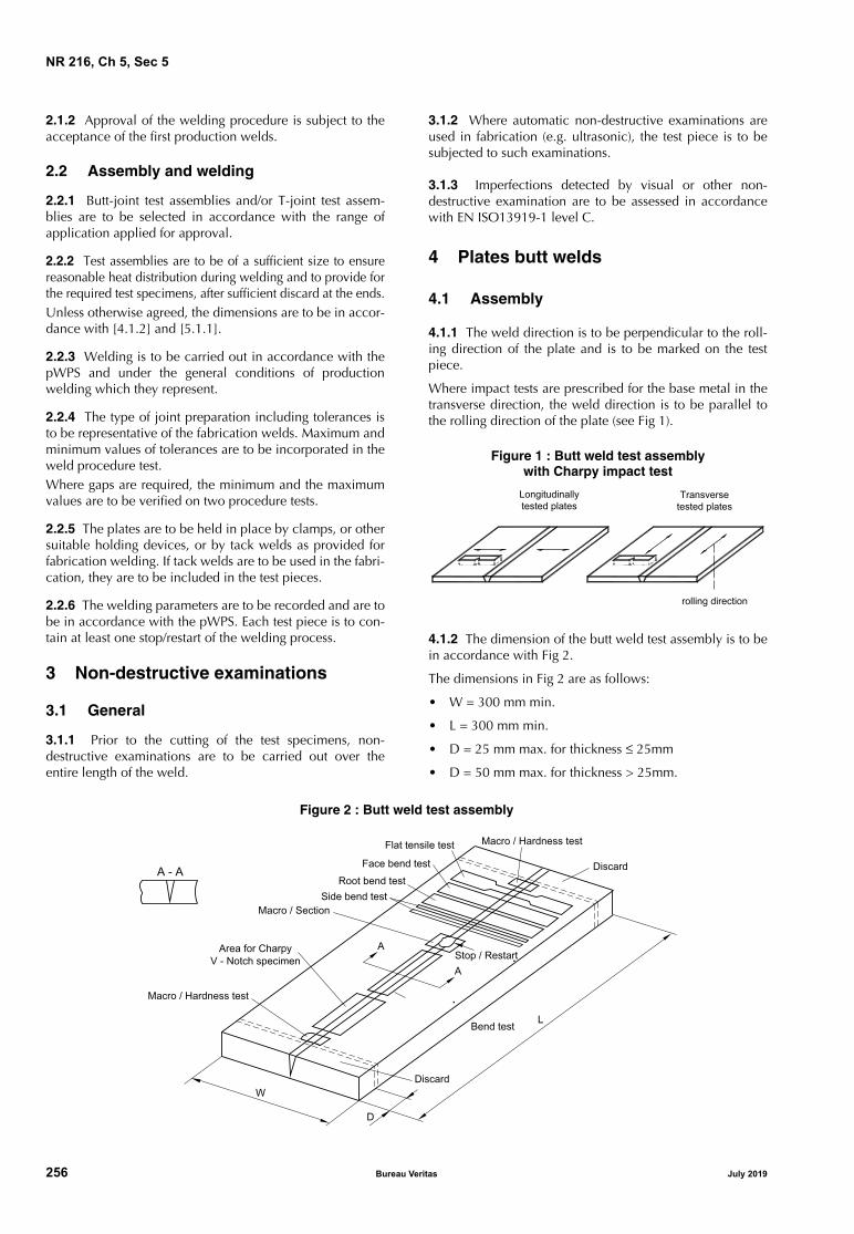
NR 216, Ch 5, Sec 5
2.1.2 Approval of the welding procedure is subject to theacceptance of the first production welds.
2.2 Assembly and welding
2.2.1 Butt-joint test assemblies and/or T-joint test assem-blies are to be selected in accordance with the range ofapplication applied for approval.
2.2.2 Test assemblies are to be of a sufficient size to ensurereasonable heat distribution during welding and to provide forthe required test specimens, after sufficient discard at the ends.Unless otherwise agreed, the dimensions are to be in accor-dance with [4.1.2] and [5.1.1].
2.2.3 Welding is to be carried out in accordance with thepWPS and under the general conditions of productionwelding which they represent.
2.2.4 The type of joint preparation including tolerances isto be representative of the fabrication welds. Maximum andminimum values of tolerances are to be incorporated in theweld procedure test.Where gaps are required, the minimum and the maximumvalues are to be verified on two procedure tests.
2.2.5 The plates are to be held in place by clamps, or othersuitable holding devices, or by tack welds as provided forfabrication welding. If tack welds are to be used in the fabri-cation, they are to be included in the test pieces.
2.2.6 The welding parameters are to be recorded and are tobe in accordance with the pWPS. Each test piece is to con-tain at least one stop/restart of the welding process.
3 Non-destructive examinations
3.1 General
3.1.1 Prior to the cutting of the test specimens, non-destructive examinations are to be carried out over theentire length of the weld.
3.1.2 Where automatic non-destructive examinations areused in fabrication (e.g. ultrasonic), the test piece is to besubjected to such examinations.
3.1.3 Imperfections detected by visual or other non-destructive examination are to be assessed in accordancewith EN ISO13919-1 level C.
4 Plates butt welds
4.1 Assembly
4.1.1 The weld direction is to be perpendicular to the roll-ing direction of the plate and is to be marked on the testpiece.
Where impact tests are prescribed for the base metal in thetransverse direction, the weld direction is to be parallel tothe rolling direction of the plate (see Fig 1).
Figure 1 : Butt weld test assemblywith Charpy impact test
4.1.2 The dimension of the butt weld test assembly is to bein accordance with Fig 2.
The dimensions in Fig 2 are as follows:
• W = 300 mm min.
• L = 300 mm min.
• D = 25 mm max. for thickness ≤ 25mm
• D = 50 mm max. for thickness > 25mm.
Figure 2 : Butt weld test assembly
�����������
�� ��� ��� ��� ��� �
�� ��� ���
����� ���������
� � �
���� ����� ���
���� �� ���
���� �� ���
���� �� ���
����� � ������
���� ��� ������
� � ����� ������
����� � ����� ���
�
�
������
������
����� � ����� ���
���� � ������
!�� ���
�
�
256 Bureau Veritas July 2019

NR 216, Ch 5, Sec 5
4.2 Examinations and tests
4.2.1 General
Non-destructive examinations and destructive tests are tobe in accordance with the requirements of Tab 2, while thelocation of the test specimens is to be in accordance withFig 2.
Table 2 : Examinations and tests
4.2.2 Non-destructive examinations
The requirements in Article [3] are to be complied with.Special attention is to be paid to the stop/restart positionswith respect to profile, proper fusion and absence of cracksand porosity.
4.3 Tensile tests
4.3.1 Transverse tensile test specimen and procedure is tobe in accordance with Ch 1, Sec 2.
4.3.2 The tensile strength is to be not lower than the speci-fied minimum tensile strength of the parent material. Thelocation of the fracture is to be reported, i.e. weld metal,HAZ, parent metal.
4.4 Bend tests
4.4.1 Bend test
Transverse, side and longitudinal bend specimens are to bein accordance with Ch 1, Sec 2.
The test specimens are to be bent on a mandrel having adiameter 3,5 times the thickness of the specimen; the bend-ing angle is to be 180°.
4.4.2 During the test, the specimens are not to reveal anyopen imperfection, in any direction, greater than 3 mm.Defects not initiated by a weld defect appearing at the cor-ner of the test specimen are disregarded.
4.5 Impact tests
4.5.1 Charpy V-notch impact tests are to be taken 1 mmbelow the surface of the sample transverse to the weld andwith the notch perpendicular to the material surface; theyare to be machined to the dimensions indicated in Ch 1,Sec 2, [4.2.1].
Three sets of Charpy V-notch specimens, each set including3 specimens, are to be taken as follows:
• one set with the notch along the weld metal centre linewith tolerance ± 0,1mm
• one set with the notch in the heat affected zone (HAZ)
• one set with the notch in the parent metal.
The direction of fracture is to coincide with the weld direc-tion (see Fig 3). The parent material specimens are to havethe same orientation as the specimens from the weld joint.
Figure 3 : Fracture direction of Charpy impact tests
4.5.2 The test temperature and the results are to complywith the requirements specified for the parent metal.
4.5.3 Requirements for reduced Charpy V specimens aregiven in Ch 1, Sec 2, [4.2.2].
4.5.4 The Society may require additional tests, e.g. Charpytests with other notch locations, and other or additionaltemperatures or CTOD tests.
4.6 Hardness measurements
4.6.1 Hardness test
The Vickers method HV10 is generally to be used.
The indentations are to be made in the weld, heat affectedzones (HAZ) and the parent metal, with the object of mea-suring and recording the range of values in the weld joint(see Fig 4). For butt welds, the upper and lower rows are totransverse 2 mm maximum below the surface, dependingon the plate thickness.
For each row of indentations, a minimum of 3 individualindentations is required in the weld, both sides of the HAZand the parent metal.
For the HAZ, the indentations are to be placed as close aspossible to the fusion line.
Type Extent
Visual examination 100%
Radiographic examination 100%
Magnetic particle examination 100%
Transverse tensile test 2 specimens
Transverse bend tests (1) 2 root and 2 face specimens
Longitudinal bend test 1 face specimen
Impact tests (2) 3 sets
Macro examination 3 sections
Hardness test 2 sections
(1) The face and root bends are preferably to be replacedby 4 side bends for t ≥ 12 mm.
(2) 3 sets of 3 specimens as per [4.5.1].
Weld direction
Orientation of charpyspecimens (notch position)
July 2019 Bureau Veritas 257

NR 216, Ch 5, Sec 5
Figure 4 : Butt weld hardness indentations
4.6.2 Where no filler metal or low hydrogen welding con-sumables (H5) are used in the procedure, values not higherthan 380HV are considered acceptable; one individualvalue not higher than 400HV is accepted for each section.
Values not higher than 350HV are required in all othercases.
4.7 Metallographic examination
4.7.1 The three macro sections are to be taken as shown inFig 2.
One section is to be a length of weld including a stop/restartposition. This longitudinal section is to be cut as shown inFig 5 and examined at the mid-thickness of the plate.
Figure 5 : Longitudinal mid-thickness macro section
4.7.2 The test specimens are to be prepared and etched onone side only to clearly reveal the fusion line, the HAZ, thesolidification structure of the weld metal and the unaffectedparent metal.
4.7.3 The sections are to be examined by the naked eye (orby low power hand lens if deemed necessary) for anyimperfection present in the weld metal and HAZ and forunsatisfactory profile features. Any imperfections are to beassessed in accordance with Article [3].
4.7.4 The weld shape is to be within the limits specified inFig 6. For thicknesses up to 8 mm, lower values for “d” and“d1“may be accepted at the discretion of the Society.
Figure 6 : Weld shape limitations
d : Minimum weld width, with d ≥ 1,5 mmd1 : Weld root width, with d1 ≥ 1,0 mm
D/d : Secondary wide zone “bulge”, if bulging occurs
D/d ≤ 1,2
5 T joint weld procedure test
5.1 Assembly
5.1.1 The dimensions of the T-joint weld test assembly areto be in accordance with Fig 7.
The dimensions in Fig 7 are as follows:
• W = 300 mm min.
• L = 1000 mm min.
• D = 50 mm max.
5.2 Examinations and tests
5.2.1 GeneralNon-destructive examinations and destructive tests are tobe in accordance with the requirements of Tab 3, while thelocation of the test specimens is to be in accordance withFig 7.
Figure 7 : T-joint test assembly
Stop / Restart
Cut
t / 2
t
d
D
with
in 7
0%
of w
eld
dept
h
d1
W/2
Fracture
Fracture
Fracture
Fracture Macro L
Stop/Restart
W
DMacro
Macro
258 Bureau Veritas July 2019

NR 216, Ch 5, Sec 5
Table 3 : Examinations and tests
5.2.2 Non-destructive examination
The requirements in Article [3] are to be complied with.Special attention is to be paid to the stop/restart positionswith respect to profile, proper fusion and absence of craterdefects.
5.2.3 Macro examination
The three macro sections are to be taken as shown in Fig 7.
Two sections are to be taken from the ends adjacent to thediscards, the third from the middle of the length.
5.2.4 Hardness test
Hardness indentations are to be made as shown in Fig 8 inaccordance with [4.6.1], as appropriate. All hardness valuesare to be recorded. The values are to comply with therequirements in [4.6.2].
Figure 8 : T joint weld hardness indentations
5.2.5 Break test
Break test specimens are to be taken from the length of thewelded assembly remaining after removal of the macro sec-tions. Four test specimens (not less than 100 mm each inlength) are to be taken and fractured by folding the uprightplate in alternate directions onto the through plate (see Fig 7).
A saw cut may be made to facilitate breaking in accordancewith Fig 9.
Figure 9 : Break test
The fracture surfaces are to be examined for possible defectswhich are to be assessed in accordance with Article [3]. Note 1: If a break in the weld cannot be obtained, an alternative isto machine the base plate flush to the web and to X-ray the weld inthe direction of weld centre line.
6 Re-testing
6.1 Non-destructive and destructive tests
6.1.1 If the test piece fails to comply with any of therequirements for visual or non-destructive testing, one fur-ther test piece is to be welded and subjected to the sameexamination.If this additional test piece does not comply with the relevantrequirements, the pWPS is to be regarded as not capable ofcomplying with the requirements without modification.
6.1.2 If any test specimens fails to comply with the relevantrequirements for destructive testing due to weld imperfec-tion only, two further test specimens shall be obtained foreach one that failed. These specimens can be taken fromthe same test piece if there is sufficient material available orfrom a new test piece, and is to be subjected to the sametest. If either of these additional test specimens does notcomply with the relevant requirements, the pWPS is to beregarded as not capable of complying with the require-ments without modification.
6.1.3 If a tensile test specimen fails to meet the require-ments, the re-testing is to be in accordance with Ch 1, Sec2, [2.3].
6.1.4 The re-testing of Charpy V-notch impact test specimensare to be carried out in accordance with Ch 1, Sec 2, [4.4].
7 Range of approval
7.1 Parent metal
7.1.1 Approval is given to that grade tested.
7.2 Thickness
7.2.1 The approval of a procedure carried out on a weldedassembly of thickness t is valid for the range 0,80t to 1,2t.Speed and power may be changed within the limitations in[7.6.2].
7.3 Edge preparation and surface condition
7.3.1 Cutting processThe cutting processes are as follows: • thermal cut• thermal cut and sand blasted• thermal cut and ground• milled.
Other cutting methods, such as mechanical cutting (shear-ing), may be considered analogously depending on theiredge geometry and surface condition. A change in the cut-ting process requires new qualification.
Type Extent
Visual examination 100%
Magnetic particle examination 100%
Ultrasonic examination 100%
Macro examination 3 sections
Hardness test 3 sections
Break test 4 specimens (1)
(1) One specimen is to be taken from the stop/restart position.
tt
t/2 t/2
July 2019 Bureau Veritas 259

NR 216, Ch 5, Sec 5
7.3.2 Surface conditionAny major change in surface condition, such as a changefrom uncoated to shop primer coated surfaces, requires newqualification. In this context, special attention is to be paidto T-joint configurations.
7.4 Joint type, bevel
7.4.1 Butt-joints cannot cover T-joints and vice versa.
7.4.2 Any change in joint geometry with respect to thatspecified in the welding procedure qualification report(WPQR) requires new qualification.
7.5 Welding machine
7.5.1 Laser machineA procedure approved for use on one laser machine is validfor that machine and beam shape only. The approval isvalid for the focusing system used at the approval tests.
7.5.2 Modification of laser machineModifications carried out on an approved laser machine orthe use of other laser machines having the same technicalspecification (from the laser beam technology point of view)only required a reduced re-approval test, if the beamparameters are within the approved range.
7.6 Welding parameters
7.6.1 GeneralVariations within the limits described below in the weldingspeed, laser power, focusing parameters and wire feed rateare allowed to accommodate changes in material thicknessor fit-up, without need for re-approval. Monitoring of weld-ing parameters within a given procedure setting is to beapplied.
7.6.2 Laser power and welding speed
The parameter (laser power / thickness x speed) is to bewithin the range 90-120% of that originally approved (whilealso maintaining the welding speed above 0,6 m/1’).
For each resetting of parameters, one test sample is to betaken and verified for weld profile shape and freedom fromdefects by non-destructive examination.
7.6.3 Wire feed speed
The wire feed speed is to be maintained within the limitsestablished by the procedure tests.
7.6.4 Focusing optic and focus position
The focusing parameters are to be kept within the limitsspecified in accordance with recognised standards.
7.6.5 Number of runs
A change in the number of passes requires a new approval.
7.6.6 Process and shielding gas
Any change in shielding gas or plasma control gas composi-tion requires a new approval.
A change in the flow rate up to 10% is admitted.
7.6.7 Welding position
A change of the welding position requires a new approval.
7.6.8 Welding consumables
Any change of welding consumables requires a newapproval.
7.6.9 Other variables
The range of approval related to other variables may betaken according to established practice as represented inrecognised standards.
260 Bureau Veritas July 2019

Marine & Offshore Le Triangle de l’Arche - 8 Cours du Triangle - CS 50101
92937 Paris La Defense Cedex - France Tel: + 33 (0)1 55 24 70 00
https://marine-offshore.bureauveritas.com/bv-rules © 2019 Bureau Veritas – All rights reserved