rules and regulations for construction of … · 2014-12-18 · rules and regulations for...
TRANSCRIPT

RULES AND REGULATIONS
for
CONSTRUCTION OF SANITARY SEWERS, PUMPING STATIONS, AND APPURTENANCES
and
CONNECTION TO AND USE OF THE SANITARY SEWERAGE SYSTEM
of
WEST EARL SEWER AUTHORITY
November 2005 Revised June 2011 Revised April 2013
WEST EARL SEWER AUTHORITY 157 West Metzler Road, P.O. Box 725
Brownstown, Pennsylvania 17508 Phone: 717-859-3201
Fax: 717-859-3499

April 2013 CONTENTS-1
West Earl Sewer Authority Lancaster County, Pennsylvania
RULES AND REGULATIONS for CONSTRUCTION OF SANITARY SEWERS, PUMPING STATIONS, AND APPURTENANCES and
CONNECTION TO AND USE OF THE SANITARY SEWERAGE SYSTEM of WEST EARL SEWER AUTHORITY
CONTENTS 1. GENERAL
A. Definitions B. Conditions of Service and Standard of Quality C. Extensions to the Sewerage System D. Permits E. Non-Residential Waste Regulations
2. SERVICE LINES
A. General B. Materials C. Installation D. Testing and Inspection E. Detail Drawings
3. GRAVITY SEWERS
A. General B. Design
C. Materials and Equipment D. Installation E. Testing and Inspection F. Detail Drawings
4. MANHOLES A. Design
B. Materials and Equipment C. Installation D. Testing and Inspection E. Detail Drawings

April 2013 CONTENTS-2
5. SANITARY SEWER LATERALS
A. General B. Design C. Materials and Equipment D. Installation E. Testing and Inspection F. Detail Drawings
6. LOW PRESSURE SEWERS A. General B. Design C. Materials and Equipment D. Installation E. Testing and Inspection F. Detail Drawings
7. GRINDER PUMPS
A. General B. Materials and Equipment C. Installation D. Testing and Inspection E. Detail Drawings
8. FORCE MAINS
A. Design B. Materials and Equipment C. Installation D. Testing and Inspection E. Detail Drawings
9. PUMPING STATIONS
A. General B. Design Criteria C. Materials and Equipment D. Electrical Requirements E. Testing and Inspection
10. INDIVIDUAL ON-LOT SUPPLEMENTAL SEWAGE PUMPS A. Intention B. General C. Inspection
11. EASEMENTS A. General B. Requirements for Developers/Extendors

April 2013 CONTENTS-3
APPENDICES APPENDIX A: Administrative Procedures for Constructing Extensions to the Sewerage System
APPENDIX B: Detail Drawings
APPENDIX C: Individual Grinder Pump Management Plan

April 2013 CONTENTS-4
APPENDICES

April 2013 GENERAL 1-1
SECTION 1 - GENERAL A. DEFINITIONS
Applicant: The developer, organization, company, corporation, or individual who makes application to West Earl Sewer Authority to construct sanitary sewerage facilities, connect to, and/or use the Authority’s public sewerage system. Authority: West Earl Sewer Authority, a Pennsylvania municipal authority, acting by and through its Board or, in appropriate cases, acting by or through its authorized representative. Authority Engineer: An engineer retained or employed by the Authority, including any authorized member of the staff of such engineer. Building/Dwelling: A structure built, erected and framed of component structural parts designed for the housing, shelter, enclosure, or support of persons, animals or property of any kind. This definition shall include structures built on-site or any remote location or factory. Building Sewer: Shall mean that part of the main building or house drain or sewer line inside the walls of the building and extending through the wall and connecting to the Service Line. Cellar Drain: Shall mean a protected and trapped drain for the purpose of carrying off spent waters from the basement of a dwelling, factory, laboratory, workshop, or other building, but excluding any drainage resulting from rain water, springs, wells, or other ground or surface water. Connection: The jointure, or the process of making the jointure, of the Service Line with the Sewer Lateral. Contractor: Individual, company or corporation which performs the installation of sewers and/or pumps and pumping stations. Extendor or Developer: Any individual, partnership, company or corporation which promotes and effects the construction of sanitary sewers and/or pumping stations, THE OWNERSHIP OF WHICH IS INTENDED TO BE DEDICATED TO THE AUTHORITY. Garbage: Means solid wastes resulting from preparation, cooking, and dispensing of food and from handling, storage and sale of produce. Improved Property: Any property upon which there is erected any structure intended for continuous or periodic habitation, occupancy or use by human beings or animals and from which sanitary sewage and/or non-residential wastes shall be or may be discharged. Inspector: A duly authorized representative of West Earl Sewer Authority who is qualified to perform inspection of the construction of sewage facilities in accordance with Authority regulations.

April 2013 GENERAL 1-2
Manhole: A structure leading from the surface of the ground to a sewer, permitting access to the sewer. Natural Outlet: Any outlet into a water course, ditch, pond, lake or other body of surface or ground water. Non-residential Waste: Any solid, liquid, or gaseous substance or water-borne waste or form of energy discharged or escaping in the course of any industrial, manufacturing, trade, or business process or in the course of the development, recovering, or processing of natural resources, but not sanitary sewage. Non-Residential User: Any industrial, commercial, or institutional facility or property as designated in accordance with the Authority’s Resolution Governing Admission of Non-residential Waste into the West Earl Sewerage System. Owner: Any person vested with Ownership, legal or equitable, sole or partial, of any improved property situated in the service area of the Authority. Person: Any individual, partnership, co-partnership, firm, company, association, society, corporation, joint stock company, trust, estate, government entity, or any other legal entity or their legal representatives, agents, or assigns. The masculine gender shall include the feminine, the singular shall include the plural where indicated by the context. Plumbing Fixture: Means any receptacle intended to receive and discharge any liquid, water, or water carried waste into a Service Line. Professional Engineer: Means an individual licensed and registered under the laws of the Commonwealth of Pennsylvania to engage in the practice of engineering. Professional Land Surveyor: Means an individual licensed and registered under the laws of the Commonwealth of Pennsylvania to engage in the practice of surveying. Sanitary Sewage: The normal water-carried household and toilet waste from any improved property, excluding, however, the effluent from septic tanks, cesspools, rain, storm and ground water, as well as roof or surface water, drainage or percolating or seeping waters, or accumulation thereof, whether underground or in cellars or basements. Sanitary Sewer: A sewer which is part of the sewerage system and which carries sanitary sewage and/or authorized non-residential waste and to which storm, surface, and ground waters are not intentionally admitted. Service Area: The geographic area of sewerage facilities tributary to West Earl Sewer Authority’s Brownstown Wastewater Treatment Plant, as defined and depicted in the West Earl Township Act 537 Plan, latest edition.

April 2013 GENERAL 1-3
Service Line/Connection: That part of the main house drain or sewer line extending from the outer building wall or foundation wall to its connection with the sewer lateral. Sewage Treatment Plant: See the definition for Wastewater Treatment Plant. Sewer: Any pipe or conduit constituting a part of the sewerage system and used for carrying sanitary sewage or authorized non-residential waste. Sewer Lateral: That section of a sanitary sewer which extends from the main sewer to the property which it serves and connects to the service line generally at a point on the inside face of the curb or edge of pavement if no curb. Sewerage System: A publicly owned treatment works (POTW) as defined by Section 212 of the Clean Water Act (33 U.S.C. 1292). In this case, the sewerage system includes all sewer mains, sewer laterals, sewage pumping stations, sewer force mains, a wastewater treatment plant, and all appurtenant facilities owned and operated by West Earl Sewer Authority in furnishing sewer service. Soil Pipe or Waste Pipe: Shall mean any pipe receiving the discharge of one or more plumbing fixtures within a building. State: Commonwealth of Pennsylvania. Storm Sewer or Storm Drain: A pipe or conduit which carries storm/surface water, drainage. Street: A public way including any highway, street, road, lane, court, public square, alley or other passageway. Township: West Earl Township, Lancaster County, Pennsylvania, a Pennsylvania municipal authority, acting by and through its Board of Supervisors or, in appropriate cases, acting by or through its authorized representative. Unauthorized Waste: Any waste which is not in compliance with the provisions of the Authority’s Resolution Governing the Admission of Non-residential Waste into the West Earl Sewerage System. Unground Garbage: Means Garbage that has not been shredded to such a degree that all its particles will be carried freely under normal sewer flow conditions, with no particle greater than one-half (1/2) inch in any dimension. User: Any person who contributes, causes, or permits the contribution of sanitary sewage or authorized non-residential waste into the Authority’s sewerage system. Vent Pipe: Shall mean any pipe extended vertically from a sewer soil pipe or waste pipe, service line or sewer to provide ventilation for the system of piping and to prevent siphonage and back pressure.

April 2013 GENERAL 1-4
Wastewater: The liquid or water-carried sanitary sewage or authorized non-residential waste from dwellings, commercial buildings, industrial facilities, and institutions, whether treated or untreated, which is contributed into or permitted to enter the sewerage system. Wastewater Treatment Plant: The portion of the sewerage system designed to provide treatment of sanitary sewage and authorized non-residential waste. It generally includes but is not limited to any arrangement of devices and structures used for treating wastewater. West Earl Sewer Authority owns and operates one such facility known as the Brownstown Wastewater Treatment Plant.
B. CONDITIONS OF SERVICE AND STANDARD OF QUALITY
1. No connection, through which sanitary sewage or authorized non-residential Waste does or may enter the sewerage system, shall be constructed, altered, repaired, or allowed to exist, which does not comply with these Rules and Regulations. Copies of these Rules and Regulations may be purchased from the Authority at the cost listed in the Authority’s Schedule of Charges and Fees.
2. All construction, reconstruction, and alterations of sewer connections and appurtenances
shall be performed in a competent, workmanlike manner in accordance with recognized standards of the plumbing trade and specifications currently on file with the Authority. The Authority in its sole discretion may stop, or require reconstruction of, any work not conforming to these standards or specifications.
C. EXTENSIONS TO THE SEWERAGE SYSTEM
1. Where an individual, builder, or developer desires to extend sewerage service to a house or to a group of houses within a development, he may do so after having made proper written application to the Authority in accordance with the Authority’s Administrative Procedures for Constructing Extensions to the Sewerage System included in Appendix A and having met all of the conditions of these Rules and Regulations. All extensions so constructed shall include, without limitation, all laterals, sewers, connections and other necessary appurtenances and shall be constructed by and at the expense of the Extendor. All construction shall be done in accordance with plans and specifications approved by the Authority prior to the start of construction, and subject to inspection, testing, and approval by the Authority or its designated representative. All open pipe ends created by the construction of gravity sewers and force mains shall be sealed with watertight removal plugs.
2. Plans and Specifications
a. Construction Drawings

April 2013 GENERAL 1-5
Complete drawings must be prepared for all facilities and shall include:
(1) An overall plot plan of the collection system showing the location of sewers and manholes together with manhole numbers and arrows depicting the direction of flow in sewers.
(2) Plans of the sewer lines and force mains at 1 inch to 50 feet scale.
(3) Profiles of sewer lines and force mains at 1 inch to 50 feet horizontal scale and 1
inch to 10 feet vertical scale, showing existing and proposed grade and invert elevations to the Authority's datum (USGS).
(4) Plans and profiles of sewer lines shown on the same sheet and shall include all
relevant rights-of-way, property lines, existing buildings, utilities, and other pertinent details necessary for construction of the facilities.
(5) Plans, sections and details of pumping stations and related facilities at suitable
scales large enough to show clearly what is intended.
b. Record Drawings (As-Builts)
Record drawings of sewers, force mains, pumps, pumping stations, and other facilities which discharge sewage to the Authority's sewer system shall be prepared and submitted to the Authority when construction has been completed. The drawings shall be to scales as described in subparagraph 2a above and shall be an accurate representation of the work as completed. Sewer profile elevations shall be re-surveyed and construction plans up-dated accordingly. The record drawings shall bear signature of a professional engineer attesting to their accuracy, and shall bear the following note:
"All work shown on these drawings has been done in accordance with the specifications of the West Earl Sewer Authority."
Record drawings shall consist of three print copies and two digital copies (one CAD and on PDF) of the newly constructed facilities.
c. Specifications
The materials to be used shall be specified on the construction drawings. The Authority reserves the right to require the submission of written specifications of any aspect of the construction which deviates from these Rules and Regulations.
d. Shop Drawings

April 2013 GENERAL 1-6
The Authority reserves the right to require the submission of shop drawings for any or all items to be used in the construction of the facilities. Approval of shop drawings must be obtained prior to installation of such items.
e. Inspection and Testing
All construction work performed under these regulations shall be subject to inspection by the Authority and satisfactory testing. No sanitary sewers, pumps, pumping stations, force mains, lateral connections, service lines and other sewerage facilities shall be connected to the Authority's sewerage system until such inspection has been carried out and approval given by the Inspector.
The Contractor or Extendor shall notify the Inspector at least 48 hours in advance of the commencement of any construction activities requiring an inspection. All sub-surface construction shall be inspected and tested before any backfilling is done.
Testing of sewer lines, manholes and other facilities is described in detail in these Rules and Regulations.
All inspection cost shall be borne by the Owner or Extendor, not the Authority.
D. PERMITS
1. No person shall uncover, connect with, make any opening into, or use, alter or disturb in any manner any sewer without first making application for and obtaining a permit, in writing, from the Authority. Application to the Authority for a permit required hereunder shall be made by the Owner of the improved property to be served, in such form as may be prescribed by the Authority. The application shall be accompanied by such tapping, connection, and/or other fees as set forth in the Authority’s Schedule of Charges and Fees, which is updated annually.
2. Street and highway openings:
a. Whenever the surface of any public street, sidewalk, or cartway is disturbed by
construction of the sewer lines, it will be the responsibility of the Developer or Extendor to secure and maintain street opening permits from the municipality having jurisdiction.
b. Highway Occupancy Permits for any work to be performed in state highways shall be
obtained by the Authority upon request by the Developer or Extendor.
3. No Connection to the sewerage system shall be made except under the supervision of the Authority or its authorized representative. The application and its acceptance by the Authority shall constitute, from the date of acceptance by the Authority, a contract obligating the applicant to pay applicable rates and charges as set forth in the Authority’s

April 2013 GENERAL 1-7
Schedule of Charges and Fees and to comply with these Rules and Regulations, as most recently amended.
4. Sewer service shall be furnished only after:
a. The Owner of the improved property to be served shall have installed, at his own cost
and expense, the service line in accordance with these Rules and Regulations; and
b. The Authority has inspected and observed testing of said service line and approved such facilities as complying with these Rules and Regulations.
5. Whenever an improved property that is connected to the sewerage system is vacated, the
Owner shall give prompt notice to the Authority.
6. Whenever an improved property that is connected to the sewerage system is sold, or otherwise conveyed, the purchaser and/or the seller shall promptly notify the Authority of such sale or conveyance.
E. NON-RESIDENTIAL WASTE REGULATIONS
1. On April 10, 2002, West Earl Sewer Authority adopted Resolution 4-10-02-1, Resolution Governing the Admission of Non-residential Waste in the West Earl Sewerage System. By this action, all discharges to the Authority sewerage system shall be in full compliance with the Non-residential Waste Resolution, and amended February 27, 2008 by Resolution 2-27-08-01.
2. The Authority is responsible for the administration and enforcement of the Non-
residential Waste Program. Any person wishing to discharge non-residential waste to the Authority sewerage system shall coordinate such action directly with the Authority.
3. Any person who discharges or causes to be discharged any water, sanitary sewage, or non-
residential waste containing any substance or possessing any characteristic prohibited by or in violation with the Non-residential Waste Resolution, shall be subject to the enforcement actions described in the Resolution.
END OF SECTION
April 2013 SERVICE LINES 2-1
SECTION 2 - SERVICE LINES A. GENERAL
1. Scope A service line shall consist of all piping, cleanouts, vents, traps, pipe sleeves, grinder
pump units, and appurtenances installed from the dwelling or building to the receiving end of the Authority’s sewer lateral. Service lines are depicted in the Detail Drawings contained in Appendix B.
Technical specifications for grinder pump service lines are contained in SECTION 6 -
LOW PRESSURE SEWERS and SECTION 7 - GRINDER PUMPS of these Rules and Regulations. Therefore, the technical specifications contained in this section primarily apply to gravity service lines and the gravity portion of grinder pump service lines.
2. Individual Service Lines Each improved property shall have its own individual service line. Each side of a double
house having a solid vertical partition wall shall be considered a separate property requiring individual sewer connections.
Where premises in single ownership consist of more than one building, the Authority
reserves the right to determine, under the circumstances of each case, whether each separate building must have its individual sewer connection or whether all buildings together may use a single connection.
For non-residential connections, the Authority may require that a wastewater flow meter
and monitoring manhole, as depicted in the Detail Drawings contained in Appendix B, be installed.
3. Maintenance and Repair of Service Lines
All service lines shall be maintained and repaired by the Owner at the cost of the Owner of the improved property. Such repairs shall be subject to the approval and inspection of the Authority. The Authority will not be responsible for any damage to properties that may result from blockage of a service line.
4. Right of Access
The Authority, by its agents and employees, shall have the right at all reasonable times, to enter any premises connected with or about to be connected with the sewerage system in order to enforce compliance with these Rules and Regulations.

April 2013 SERVICE LINES 2-2
5. Existing Service Lines
Existing service lines may be utilized provided that they have been inspected by the Authority and found to be reasonably true to grade and alignment, in good condition for the purpose of conveying sanitary sewage or authorized non-residential wastes, and have tight joints of approved materials. The integrity of the existing line shall be determined by performing the air test described later in the chapter under Testing and Inspection. If the existing line does not conform to these requirements, the line shall be corrected or a new line shall be laid at the expense of the Owner in accordance with the specifications contained herein. All testing required by the Authority shall be at the expense of the Owner.
6. Prohibited Discharges and Wastes Prohibited discharges and wastes are described in the Authority’s Non-residential Waste
Resolution. In particular, the discharge of septic waste, unauthorized non-residential waste, stormwater, surface water, springwater, groundwater, and foundation drainage from floor drains, roof drains, and sump pumps is strictly prohibited by Authority and state regulations. Persons found to be responsible for such prohibited discharges shall be subject to penalties of the Authority and state.
B. MATERIALS
1. Gravity Service Line Pipe Gravity service line pipe shall have a minimum internal diameter of 4 inches. In normal,
good ground conditions cast iron, ductile iron, or PVC pipe shall be used. Under driveways, parking lots, or where directed by the Authority, cast iron, ductile iron, or Schedule 40 (or 80) PVC pipe shall be used with pipe bedding and backfill as required within Township roads. Specifications for these different pipe materials are as follow. a. Cast Iron Pipe and Fittings Cast iron pipe shall be medium or service weight conforming to ASTM Designation
A74 or the standards of the Cast Iron Soil Pipe Institute. Pipe shall be supplied in standard lengths as much as possible.
Jointing materials shall have approved pre-moulded rubber joints made with bell
and spigot ends. Portland cement joints will not be permitted. b. Ductile Iron Pipe and Fittings
Ductile iron pipe shall conform to AWWA C151 and AST A746 standards. Pipe shall be supplied in standard lengths as much as possible. Minimum thickness design shall be per AWWA C150 for Class 50 DIP. Ductile iron pipe shall be by U.S.
April 2013 SERVICE LINES 2-3
Pipe and Foundry Company, American Ductile Iron Pipe Company, or Griffin Pipe Products Company. Joints shall be rubber-gasket push-on type or rubber-gasket mechanical joint type conforming to AWWA C111. Gasket shall be of SBR. Ductile iron pipe and fittings for use in gravity service lines shall be lined with either Protecto 401 ceramic-filled amine cured epoxy or SewperCoat calcium aluminate mortar as manufactured by Lafarge Calcium Aluminates. These linings shall be applied in accordance with the manufacturer’s recommendations.
c. Plastic Pipe.
Plastic pipes for gravity service lines shall be SDR 35 (ASTM D3034) or Schedule 40 PVC (ASTM D1785) solid wall pipe. Use of foam-core drain-waste-vent pipe shall not be permitted. SDR 35 PVC shall have bell and spigot push-on joints. The bell shall consist of an integral wall section with a solid cross-section elastomeric gasket (as manufactured by J.M. Manufacturing Co. or approved equal) securely locked in place to prevent displacement during assembly. Installation of elastomeric gasketed joints and performance of the joint shall conform to ASTM F477, ASTM D3139 or ASTM D3212.
Schedule 40 PVC pipe shall have either: (1) joints of O-ring gaskets, or an O-ring adapter manufactured of rubber, and shall be installed in accordance with the manufacturer’s recommendations; or (2) glued joints. Pipe ends shall be cleaned, primed, glued and installed in accordance with the manufacturer’s recommendations.
2. Flexible Couplings Flexible couplings composed of elastomeric PVC shall conform to ASTM C443, C425,
C564 and D1869 as manufactured by Fernco, Inc. Each coupling shall be supplied with two (Type 305C-305) stainless steel adjustable clamps. Flexible couplings shall only be permitted in specific circumstances and only with prior approval by Authority and/or Authority Engineer.
3. Cleanouts Cleanouts shall be constructed using a wye fitting in the run of the pipe with a 45-degree
bend (1/8th bend) and risers to the ground surface. The riser shall be provided with a standard 4-inch diameter, water tight, screw type cap. Risers on gravity sewer laterals connecting to grinder pumps basins shall be provided with a 4-inch diameter

April 2013 SERVICE LINES 2-4
ferrous/PVC vent pipe cap. The wye fitting and riser pipe shall be of the same or higher grade as the service line pipe.
4. Traps and Vents The trap shall be a cast iron, ductile iron, or Schedule 40 PVC (or higher grade) single
running trap with vent. The riser and vent shall be on the building side of the trap. The riser pipe shall be of the same or higher grade as the service line pipe.
5. Pipe Sleeves Pipe sleeves through building or foundation walls shall be at least medium or service
weight cast iron or well casing grade steel. Pipe shall be at least 6 inches in diameter or two pipe diameter sizes larger than the service line, whichever is greater.
6. Detection Tape
Following installation and backfill of service lines, detectable warning tape shall be installed at the top of the trench not more than 12 inches below finished grade. Detection tape shall be a metal detectable reinforced underground utility marking tape with a 50 gauge (0.0005”) solid aluminum foil core with permanent printing under a mylar layer. The detection tape shall consist of a minimum 9.0 mil (0.0009”) overall thickness, coated and colored cross woven polyethylene, with no less than 2,500 lbs. of tensile break strength per 12” width and color coded suitable for direct burial. Detection tape shall be 2-inch width minimum.
C. INSTALLATION 1. Qualified Installer Installation of all service lines shall be performed by plumbers who are properly insured,
experienced with such work, and familiar with these Rules and Regulations. 2. Minimum Cover A minimum cover of 3.5 feet shall be maintained to prevent crushing and freezing, unless
the Authority approves a lesser minimum cover. Minimum cover in drives, parking areas, and streets shall be 4 feet.
3. Alignment All service lines shall be installed with a minimum grade of 2 percent. A straight
horizontal alignment shall be maintained where possible. When conditions exist that require the use of bends (ell fittings) in the line, the following shall apply:

April 2013 SERVICE LINES 2-5
a. It shall be incumbent on the contractor to contact the inspector prior to excavation to discuss the proposed route of the service line and the use of bends in the line.
b. Measures shall be taken by the contractor to minimize the number of bends and/or
direction changes in the service line. c. The existence of rock is not an acceptable reason for using bends. d. Cleanouts shall be provided at all horizontal bends of 45 degrees or greater. The use
of a series of multiple lesser degree bends to achieve a horizontal directional change of 45 degrees or greater shall be prohibited.
e. A 45-degree or 90-degree bend installed horizontally but rotated in a downward
orientation shall be considered a horizontal bend if the angle of rotation from the horizontal is less than 45 degrees and, thus, shall require a cleanout.
f. Vertical bends of greater than 45 degrees shall be prohibited.
4. Excavation The trench shall be excavated to a depth of six inches below the outside diameter of the
pipe barrel, or deeper if so specified. The excavation may be done by machine. The resultant subgrade shall be undisturbed, or compacted as approved by the Engineer if disturbed.
Trenched shall be dewatered prior to laying pipes. Ground and surface water in trenches
for service lines shall not be permitted to enter the sewerage system. Care shall be taken to prevent broken lateral caps and other debris from entering sewerage system.
5. Pipe Bedding The pipe shall be bedded on 6 inches of AASHTO No. 8 (or PennDOT No. 1B) stone, the
full width of the trench, and shall be covered with AASHTO No. 8 (or PennDOT No. 1B) stone to a height of 12 inches over the top of the pipe. The bedding shall be placed in 3-inch layers (uncompacted thickness) and thoroughly compacted. The bedding shall provide uniform and continuous bearing and support for the pipe at every point between the bells.
a. Unstable Subgrade
Where the bottom of the trench at subgrade is found to be unstable or to include ashes, cinders, any type of refuse, vegetable, or other organic material, or large pieces or fragments of inorganic material, which, in the opinion of the Authority, should be removed, the Extendor shall excavate and remove such unsuitable material to the width and depth recommended by the Authority. Before pipe is laid, the subgrade shall be formed by backfilling with AASHTO No. 57 (or PennDOT No. 2B) stone in 3-

April 2013 SERVICE LINES 2-6
inch (uncompacted thickness) layers thoroughly compacted to 95% of standard Proctor density and the bedding prepared as hereinbefore specified.
6. Backfill
Service line trenches may be filled with excavated material above the pipe bedding, as specified above, except that stones larger than 8 inches may not go in the trench and the fill shall not contain more than 20% stone in total volume. Backfilling material shall be deposited in the trench for its full width on each side of the pipe and fittings simultaneously. The trench shall be properly tamped in lifts not to exceed 6 inches. All bedding and backfilling shall be compacted to 95% of standard Proctor density. If the trench is in an existing street, the surface is to be restored as required by the regulating authority. Backfill within driveways and other paved areas shall be as depicted on the Detail Drawings for pipe installations within Township roads. No trench shall be backfilled until the service line has been inspected and approved by the Authority or its representative.
7. Cleanouts
Cleanouts shall be provided in each service line at intervals not greater than 50 feet and at all horizontal bends of 45 degrees or greater to permit complete rodding of the service line. If a cleanout has not been provided inside the house, then a cleanout will be required just outside the foundation wall. Cleanouts shall not be installed within road rights-of-way or driveways. Cleanouts shall be located in areas not subject to flooding or ponding.
8. Traps An intercepting trap shall be placed between the curb line and the building. The trap shall be a cast iron or PVC single running trap with vent. The riser and vent shall be on the building side of the trap. Unless otherwise authorized by the Authority or its representative, the top of the vent shall be a minimum of 4 inches above the ground and shall have a cowl type vent to prevent surface water from entering the service line. Traps and vents shall not be installed within road rights-of-way or driveways. Traps and vents shall be located in areas not subject to flooding or ponding.
9. Pipe Sleeves
At the entry of the service line into the building, a protective cast iron, ductile iron, or steel sleeve shall be provided through the wall of the building. The sleeve shall span across the excavated area outside the wall and at least two feet of the end of the sleeve

April 2013 SERVICE LINES 2-7
shall rest on virgin soil. The service line shall be threaded through the sleeve and the annular space at both ends of the sleeve sealed with non-corrosive silicon based flexible sealant.
10. Connections to Sewer Laterals
a. Where the service line and the sewer lateral are both of the same size pipe,
connections shall be made by properly joining the bell end of the service line with the sewer lateral.
b. If the service line and sewer lateral are of unlike materials, the connection may be
made with a fitting of PVC or a cast reducing coupling suitable for the type and size of pipe to be connected. Projecting the smaller pipe into the larger and sealing with grout or mastic will under no circumstances be permitted.
c. All connections to sewers shall be made at the terminus of the sewer lateral unless the
Authority specifically authorizes otherwise.
d. Whenever no sewer lateral has previously been constructed, the construction of the sewer lateral and the connection of the sewer lateral to the sewer main shall be as described in SECTION 5 - SANITARY SEWER LATERALS of these Rules and Regulations.
11. Special Conditions and Requirements
a. Where the service line is to be placed under a drive or other roadway and the depth is
less than four feet, the line shall be encased in concrete or flowable fill; or it shall be constructed of ductile iron pipe; or as the Authority may direct.
b. Any street, road, or highway surfaces which are disturbed or damaged by the Owner
or contractor shall be properly repaired at the Owner's expense. Subsequent settlement of the street, road, or highway surface resulting from improper compaction of the service line trench or failure to protect the lateral line trench shall be promptly repaired at the Owner's cost.
c. Service lines for all service stations, garages, or other establishments storing, using, or
dispensing gasoline, kerosene, benzene, or similar solvents shall be constructed of ductile iron pipe with chemically resistant joints.
d. No hotel, restaurant, boarding house, institution or public eating place shall connect
to the sewer system without first installing grease traps, of a type and size approved by the Authority or its representative and a flow monitoring manhole, in the service line at locations approved by the Authority or its representative.

April 2013 SERVICE LINES 2-8
e. No service station, garage, factory building, or commercial establishment which
handles oils, petroleum or similar products, or which washes cars, trucks, or other types of machinery, shall connect to the sewer system without first installing grease and sand traps of sizes and types approved by the Authority or its representative, and a flow monitoring manhole, in the service line or at a locations approved by the Authority or its representative.
D. TESTING AND INSPECTION
The construction of service lines shall at all times be subject to the supervision and inspection of the Authority or its duly authorized representative. No Owner shall permit service connections to be covered or backfilled until authorized by the Authority to do so. Each service line shall be subjected to a test prior to approval by the Authority. The test shall be witnessed by an agent of the Authority and the service line shall not be deemed acceptable until said service line has satisfactorily passed the test hereinafter described. All costs of testing and any subsequent test(s), including equipment, material, or labor required shall be the responsibility of the Owner. The service line shall be tested by plugging the line at the point of connection with the Authority’s system by the use of a "test tee" and by plugging the line just before the point of connection with the building sewer. All risers, vents, plugs, and cleanouts should be adequately blocked, plugged or supported to withstand the pressure associated with the test. The test shall be an air test and shall be designed to provide a residual pressure of 3.5 psi throughout the length of the service line. The air test shall be made by attaching an air compressor testing apparatus to any suitable opening and after closing and supporting all other inlets and outlets to the service line, forcing air into the service line until there is a uniform gauge pressure of 3.5 psi. The service line shall be deemed acceptable if this pressure is maintained for 15 minutes without the introduction of additional air. Care must be taken that the pressures generated by the air test do not exceed the pipe manufacturer's recommendations.
E. DETAIL DRAWINGS
Relevant detail drawings included in Appendix B are as follows:
27 Typical Gravity Service Line Connection 28 Typical Grinder Pump Service Line to Low Pressure Sewer Schematic 29 Typical Grinder Pump Service Line to Gravity Sewer Schematic 40 Pipe Bedding

April 2013 SERVICE LINES 2-9
41 Concrete Encasement 42 Lawn Restoration 43 Pavement Restoration
END OF SECTION

April 2013 GRAVITY SEWERS 3-1
SECTION 3 - GRAVITY SEWERS A. GENERAL
Developers and individuals who wish to construct extensions to the Authority’s sewerage system must familiarize themselves with the Authority’s Administrative Procedures for Constructing Extensions to the Sewerage System included in Appendix A.
B. DESIGN
1. Regulatory Agencies.
All designs shall conform to good engineering practice and all proposed sewer construction projects shall meet the requirements of the Pennsylvania Department of Environmental Protection (PADEP), OSHA, and the Pennsylvania Department of Labor and Industry, and shall conform to the requirements contained herein.
2. Diameter and Slope. The minimum sewer diameter shall be 8 inches. Minimum slopes shall be as those
which appear in the PADEP Domestic Wastewater Facilities Manual (Latest Edition). The minimum slope for all terminal sections of sewers shall be 1.0%. The maximum distance between manholes shall be 400-feet.
3. Depth of Sewers. a. All sewers shall be designed to provide a minimum depth of cover of 4.0 feet
above the top of the pipe.
b. Under normal conditions, sewer lines with depths greater than 15 feet will not be approved. If greater depths of sewers are deemed to be necessary, the design should be discussed with the Authority prior to formal submission of the plans for approval. In all cases where subsequent approval is given by the Authority, the pipe to be used shall be Class 52 epoxy lined ductile iron, minimum.
4. Location of Sewers. a. General Sewer mains shall normally be located within the right-of-way lines of public
streets. If it is necessary to locate a sewer main on private property, the Applicant shall provide a sewer easement in the name of the Authority as described in SECTION 11 - EASEMENTS of these Rules and Regulations.

April 2013 GRAVITY SEWERS 3-2
b. Utility crossings shall be minimized. Maximum horizontal separation of utilities shall be provided for ease of future maintenance and health and safety reasons.
c. Sewers near Water Mains. (1) Sewer installation near water mains shall conform to the PADEP’s Domestic
Wastewater Facilities Manual. (2) Parallel Installation: Sewers shall be laid at least 10 feet horizontally from
any existing or proposed water main. The distance shall be measured edge to edge. In cases where it is not practical to maintain a 10 foot separation, the Authority may allow deviation on a case-by-case basis, if supported by data from the design engineer. Such deviation may allow installation of the sewer closer to a water main, provided that the water main is laid in a separate trench or on an undisturbed earth shelf located on one side of the sewer at such an elevation that the bottom of the water main is at least 18 inches above the top of the sewer.
(3) Crossings: Whenever sewers must cross under water mains, the sewer shall
be laid at such an elevation that the top of the sewer is at least 18 inches below the bottom of the water main. This vertical separation shall be maintained for the portion of the sewer located within 10 feet horizontally of any water main it crosses. The 10 feet is to be measured as a perpendicular distance from the sewer line to the water line.
(4) Exception: When it is impossible to obtain the proper horizontal and vertical
separation as stipulated in Items (2) and (3) above, both the water main and sewer line shall be constructed of ductile iron pipe having mechanical joints. Other types of joints of equal or greater integrity may be used at the discretion of the Authority. Where a sewer must cross over a water main, additional protection shall be provided by:
(a) A vertical separation of at least 18 inches between the bottom of the
sewer and the top of the water line; (b) Adequate structural support for the sewers to prevent excessive
deflection of the joints and the settling on and breaking of the water line; and
(c) Centering the length of the water line at the point of the crossing so
that the joints are equidistant and as far as possible from the sewer. (5) The Authority shall be consulted when any of the above conditions cannot
be met, to discuss the use of double casing or concrete encasement of sewer and/or water lines as possible alternatives.

April 2013 GRAVITY SEWERS 3-3
(6) No water pipe shall pass through, or come into contact with, any part of a sewer manhole.
d. Sewer Mains Near Gas Mains and Other Utilities. (1) Parallel Installation: Sewer mains shall be laid at least 10 feet horizontally
from any existing or proposed gas main or other utility. The distance shall be measured edge to edge. In cases where it is not practical to maintain a 10 foot separation, the Authority may allow deviation on a case-by-case basis, if supported by data from the design engineer.
(2) Crossings: Whenever sewer mains must cross gas mains or other utilities, a
minimum vertical separation of 18 inches shall be provided measured edge to edge. This vertical separation shall be maintained for the portion of the sewer main located within 10 feet horizontally of any gas main or other utility it crosses. The 10 feet is to be measured as a perpendicular distance from the gas main or other utility to the sewer main. Where the sewer main must cross under a gas main or other utility, adequate structural support for the gas main or other utility shall be provided to prevent excessive deflection of the joints and the settling on and breaking of the sewer line.
(3) The Authority shall be consulted when any of the above conditions cannot
be met, to discuss possible alternatives. C. MATERIALS AND EQUIPMENT
1. Ductile Iron Pipe and Fittings
a. Pipe and Fittings
Ductile iron pipe and fittings shall conform to AWWA C151 and ASTM A746. Pipe shall be supplied in standard pipe lengths as much as possible. Ductile iron pipe and fittings shall be by U.S. Pipe & Foundry Company, American Ductile Iron Pipe Company, or Griffen Pipe Products Company.
b. Joints
Joints shall be rubber-gasket push-on type or rubber gasket mechanical joint type conforming to AWWA C111. Gasket shall be of SBR.
c. Minimum Thickness
Minimum pipe thickness design shall be per AWWA C150 for Class 52 DIP.

April 2013 GRAVITY SEWERS 3-4
d. Lining
Ductile iron pipe and fittings shall be lined with Protecto 401 ceramic-filled amine cured epoxy by Indrall, calcium aluminate mortar by Lafarge Calcium Aluminates, or approved equal.
2. Polyvinyl Chloride Sewer Pipe and Fittings
a. Materials
Polyvinyl chloride (PVC) sewer pipe and fittings shall be PVC SDR 35 with full diameter dimensions and shall conform to ASTM D-3034 for 4 through 15 inch diameter sizes and shall conform to ASTM F679 for 18 through 36 inch diameter sizes.
b. Joints
The pipe and fittings shall be joined with an integral bell-and-spigot type rubber-gasketed push-on joints. Each integral bell joint shall consist of a formed bell with a single locked in rubber gasket as manufactured by J.M. Manufacturing Co. or approved equal. Joints and gaskets shall conform to ASTM D-3212 and ASTM F477.
3. Alternative Gravity Sewer Pipe Materials
Alternative gravity sewer pipe materials may be considered and will be subject to approval by the Authority on a case-by-case basis. Full details of alternatives must be submitted.
4. Manhole Adapter with Sand (Sand Collar).
Pipe stubs for penetrations into existing manholes shall be PVC gasketed heavy wall “Sand Collar” sewer pipe and fitting. Pipe stub shall be type PSM SDR-26, ASTM D3034 as supplied by GPK Products, Inc.
5. Steel Casing Pipe
a. The steel casing pipe shall have a minimum yield strength of 35,000 psi, have a thickness as required but not less than 0.375 inches, be equipped with grout holes and conform to AWWA C200 and ASTM A53.
b. Casing interior and exterior shall be painted with two coats bitumastic enamel
coating in accordance with AWWA C203. c. Pipe cradles or isolators shall be as shown on the Detail Drawings contained in
Appendix B, APS casing spacers, Model SSI, or approved equal.

April 2013 GRAVITY SEWERS 3-5
d. Minimum casing diameter shall be in accordance with PennDOT or Amtrak requirements as applicable.
6. Detection Tape
Following installation and backfill of gravity sewer pipe, detectable warning tape shall be installed at the top of the trench not more than 12 inches below finished grade. Detection tape shall be a metal detectable reinforced underground utility marking tape with a 50 gauge (0.0005”) solid aluminum foil core with permanent printing under a mylar layer. The detection tape shall consist of a minimum 9.0 mil (0.0009”) overall thickness, coated and colored cross woven polyethylene, with no less than 2,500 lbs. of tensile break strength per 12” width and color coded suitable for direct burial. Detection tape shall be 2-inch width minimum.
D. INSTALLATION
1. Excavation
The trench shall be excavated to a depth of 6 inches below the outside diameter of the pipe barrel, or deeper if so specified. The width of the trench shall be as shown on the detail drawings. All of this excavation may be done by machine. The resultant subgrade shall be undisturbed, or compacted as approved by the Authority if disturbed.
When the pipe is to be laid in fill, the trench shall be compacted to 95% of standard Proctor density to a height of 12 inches above the top of the pipe.
2. Bedding
The pipe shall be bedded on 6 inches of AASHTO No. 8 (or PennDOT No. 1B) stone, the full width of the trench, and shall be covered with AASHTO No. 8 (or PennDOT No. 1B) stone to a height of 12 inches over the top of the pipe. The bedding shall be thoroughly compacted. The bedding shall provide uniform and continuous bearing and support for the pipe at every point between the bells.
a. Unstable Subgrade
Where the bottom of the trench at subgrade is found to be unstable or to include ashes, cinders, any type of refuse, vegetable, or other organic material, or large pieces or fragments of inorganic material, which, in the opinion of the Authority, should be removed, the Extendor shall excavate and remove such unsuitable material to the width and depth recommended by the Authority. Before pipe is laid, the subgrade shall be formed by backfilling with AASHTO No. 57 (or PennDOT No. 2B) stone in 3-inch (uncompacted thickness) layers thoroughly compacted to 95% of standard Proctor density and the bedding prepared as hereinbefore specified.
April 2013 GRAVITY SEWERS 3-6
b. Special Foundations
Where the bottom of the trench at the subgrade is found to consist of material which is unstable to such a degree that, in the opinion of the Authority, it cannot be removed and replaced with an approved material thoroughly compacted in place to support the pipe properly, a suitable foundation for the pipe shall be designed and submitted to the Authority for approval.
c. Concrete Encasement
Concrete encasement shall be as shown on the Detail Drawings.
3. Laying Pipe
All piping shall be laid to a uniform line and grade, bell ends upgrade, with a firm and even bearing along the barrel of the pipe. The spigot end of the pipe is to be centered in, shoved tight and secured against the bell of the previously laid pipe. The interior of each pipe shall be cleaned of all foreign material before the next pipe is laid. Pipe laying shall commence at the lowest point and proceed upgrade. At the close of each day's work, and at such other times when pipe is not being laid, the open end of the pipe shall be protected with a close fitting stopper. a. Grade and Alignment Control
Prior to construction, the Extendor shall furnish three copies of a grade sheet for each manhole run to the Authority. Grade and alignment control shall be established by one of the following methods:
(1) Laser - Direct reading (2) Twin string line offset
b. Pipe Clearance in Rocks
Ledge rock, boulders and large stones shall be removed to provide a clearance of at least 6 inches below and on each side of all pipe and fittings for pipes 24 inches in diameter or less, and 9 inches for pipes larger than 24 inches in diameter.
The specified minimum clearances are the minimum clear distances which will be permitted between any part of the pipe and/or fitting being laid and any part, projection or point of such rock, boulder or stone.
c. Pipes at Manholes or Other Rigid Structures
Pipes directly connected to or supported by rigid structures, shall not have a length beyond the rigid support in excess of that shown in the manhole Detail Drawings.

April 2013 GRAVITY SEWERS 3-7
4. Backfilling
The trench may be filled with excavated material above the AASHTO No. 8 (or PennDOT No. 1B) stone as specified above except that stones larger than 8 inches may not go in the trench and the fill shall not contain more than 20% stone in total volume.
The trench shall be properly tamped in lifts not to exceed the maximum thickness for the type of tamping equipment being used. If the trench is in an existing street, the surface is to be restored as required by the regulating authority.
All bedding and backfilling shall be compacted to 95% of standard Proctor density.
Backfilling shall not be done with frozen material. No backfilling shall be done if the material already in the trench is frozen.
Within State roads, all backfill shall be in accordance with the requirements of PennDOT Publication 408 or as specified in the PennDOT Permit issued for the project. The Detail Drawings provide a general guide for these requirements. Within Township roads, backfill shall be as depicted in the Detail Drawings.
5. Bored Crossings
a. The carrier pipe shall be installed to the exact line and grade required within the casing pipe utilizing a levelling grout course, adjustable pipe supports, or other methods as approved by the Authority.
b. The carrier pipe segments shall be supported within the casing pipe so that the
pipe bells do not rest directly on the casing. The load of the carrier pipe shall be distributed along the casing by the method of support shown on the detail drawings.
c. All work shall be performed in conformance with the requirements of PennDOT,
Conrail, or other regulatory agencies involved.
E. TESTING & INSPECTION 1. Alignment Test. After the mains have been laid and backfill (bedding) placed, the Authority's inspector
will flash a light between manholes or manhole locations to determine whether the alignment of the sewer is true and whether any pipe has been displaced, broken or otherwise damaged subsequent to laying. This test will again be conducted before final acceptance of the sewer. Each section (manhole to manhole) of sewer shall show a good

April 2013 GRAVITY SEWERS 3-8
light circle throughout its length and any and all defects shall be corrected to the satisfaction of the Authority before acceptance.
2. Allowable Deflection Test. a. Pipe deflection measured not less than 30 days after the backfill has been
completed as specified shall not exceed 5 percent. Deflection shall be computed by multiplying the amount of deflection (nominal diameter less minimum diameter when measured) by 100 and dividing by the nominal diameter of the pipe.
b. Deflection shall be measured with a rigid mandrel (Go/No Go) device cylindrical
in shape and constructed with a minimum of nine evenly spaced arms or prongs. Drawings of the mandrel with complete dimensions shall be submitted to the Engineer for each diameter of pipe to be tested. The mandrel shall be hand pulled through all sewer lines. Provide certification that these tests have been conducted to the Authority. These tests must be witnessed and approved by the Engineer or the Authority.
c. Any section of sewer not passing the mandrel shall be uncovered and the bedding
and backfill replaced to prevent excessive deflection. Repaired pipe shall be retested and shall not deflect more than 4 percent.
3. Leakage Test. a. General (1) Sewers shall be tested for leakage only after all sewers and sewer laterals,
including stoppers, are installed. Each sewer section between manholes including all laterals will be tested with low pressure air. Testing will be done only after all backfilling has been completed and trench settlement has been minimized. The Applicant shall furnish all labor, materials, tools, equipment and accessories necessary to perform the required tests. All tests shall be made in the presence of, and to the complete satisfaction of the Authority or the Authority’s inspector.
(2) Submit copies of test conditions and results to the Authority for each section
tested. (3) Test the first section of pipeline as soon as it is installed to demonstrate that
the work conforms to this Section. (4) Testing of pipe shall closely follow pipe laying. No more than 1000 ft of
pipe shall remain untested at any time.
April 2013 GRAVITY SEWERS 3-9
(5) Contractor shall notify the customers when service will be interrupted for testing.
b. Exfiltration Test with Air (1) Submit the proposed method of testing to the Engineer or the Authority for
approval. Air testing shall be performed in accordance with the procedures described in UNI-B-6-98 (PVC or DI), ASTM C828 (Clay), or ASTM C924 (Concrete) for the appropriate pipe material.
(2) The equipment shall be specifically designed and manufactured for testing
pipelines with low pressure air and shall be provided with an air regulator valve or air safety valve set to prevent the air pressure in the pipeline from exceeding 9 psig. It is extremely important that all plugs be installed and braced to prevent blowouts. Note that the force of 250 pounds is exerted on an 8-inch plug by an internal pressure of 5-psig, and a force of 5,090 pounds is exerted on a 36-inch plug by an internal pressure of 5 psig. No persons should be allowed in the alignment of the pipe during testing. Care must be taken that the pressures generated by the air testing equipment do not exceed the pipe manufacturer's recommendations.
(3) The above ground air control equipment shall include a shut-off valve,
pressure regulating valve, pressure relief valve, input pressure gauge and a continuous monitoring pressure gauge having a range from 0 to 10 or 15 psi. The continuous monitoring gauge shall be no less than 4-inches in diameter with minimum divisions of 0.10 psi and an accuracy of ±0.04 psi.
(4) Low pressure air shall be slowly introduced into the sealed line until the
internal air pressure reaches 4.0 psig greater than the average back pressure of any groundwater above the pipe, but not greater than 9.0 psig. The air pressure correction which must be added to the 4.0 psig normal test starting pressure shall be calculated by dividing the average vertical height in feet of groundwater above the top of the sewer to be tested by 2.31. The result gives the air pressure correction in pounds per square inch (psi) to be added.
(5) After a constant pressure of 4.0 psig (greater than the average groundwater
back pressure over the pipe) is reached, the air supply shall be throttled to maintain that internal pressure for at least 2 minutes. This time permits the temperature of the entering air to equalize with the temperature of the pipe wall.
(6) When the temperatures have been equalized and the pressure stabilized at
4.0 psig (greater than the average groundwater backpressure), the air hose from the control panel to the air supply shall be shut off or disconnected. The continuous monitoring pressure gauge shall then be observed for a

April 2013 GRAVITY SEWERS 3-10
period of 5 minutes, during which the pressure shall not decrease below 4.0 psig (greater than the average groundwater backpressure over the pipe).
(7) If the results of the air test are unsatisfactory, the Owner shall, at his own
expense, determine the source of the leakage and make all necessary corrections and retest. The extent and type of repair which may be allowed, as well as results, shall be subject to approval of the Engineer or the Authority.
4. Cleaning
At the conclusion of the work, thoroughly clean all pipelines by flushing with water or other means to remove all dirt, stones, pieces of wood, or other material which may have entered the pipes during the construction period. Debris cleaned from the lines shall be removed from the low end of the pipeline. If after this cleaning, obstructions remain, they shall be removed. After the pipelines are cleaned and if the groundwater level is above the pipe or following a heavy rain, the Engineer will examine the pipes for leaks. If any defective pipes or joints are discovered, they shall be repaired or replaced as directed by the Engineer or Authority.
F. DETAIL DRAWINGS
Relevant detail drawings included in Appendix B are as follows:
1 Precast Concrete Manhole 2 Precast Concrete Inside Drop Manhole 24 New Sewer to Existing Manhole Connection 25 New Sewer to Existing Manhole Connection – Inside Drop 27 Typical Gravity Service Line Connection 30 Shallow Sewer Service Connection 31 Deep Sewer Service Connection 35 Pipe Cradle in Casing 40 Pipe Bedding 41 Concrete Encasement 42 Lawn Restoration 43 Pavement Restoration
END OF SECTION

April 2013 MANHOLES 4-1
SECTION 4 - MANHOLES A. DESIGN
Manholes between gravity sewers shall be placed at all pipe intersections and at intervals not greater than 400 feet. Manholes shall be placed at all changes in grade, pipe size, and alignment. External drop manholes are required if the invert of the incoming pipe is greater than 2 feet above the invert of the outgoing pipe. Inside drop manholes shall be lined with T-Lok PVC or HDPE, where required. Lining shall cover the invert, walls, and corbelled top up to the cast iron manhole frame.
Unless otherwise noted, manholes shall be constructed of precast concrete with cast iron frames and covers, as shown on the Detail Drawings included in Appendix B. The invert channels shall be smooth and semicircular in shape conforming to the inside of the adjacent sewer section. Changes in direction of flow shall be with a smooth curve of as large a radius as the size of the manhole will permit.
All manholes shall be adjusted to finished grade. If an extension is made from an existing manhole that will be below finished grade, the manhole frame shall be raised to finished grade in paved areas and 18 inches above grade in rights-of-way or unpaved areas, at the expense of the Extendor. If a manhole is to be at grade in unpaved areas, a watertight manhole frame and cover assembly shall be installed by the Extendor. If the proposed construction includes an existing street or right-of-way in which the existing grade will be changed, the Extendor shall be responsible for adjusting all existing manholes to finished grade. All adjustments required shall be in accordance with methods approved by the Authority. Such approval must be obtained in writing prior to construction.
Liftholes in manholes shall not extend through the entire width of the wall.
Manholes shall be constructed in accordance with the Detail Drawings contained in Appendix B. Shop drawings shall be submitted for approval.
B. MATERIALS AND EQUIPMENT
1. Precast Reinforced Concrete Manhole Riser and Tops
Precast reinforced concrete manhole risers and tops shall conform to ASTM Specification C-478 Latest Edition and shall be of watertight construction. All internal and external surfaces shall be coated or lined. Seal tongue and groove joints of precast sections with either rubber O-ring gasket or preformed flexible joint sealant. O-ring rubber gaskets shall conform to ASTM C443. Preformed flexible joint sealant shall conform to ASTM C990 and shall be Kent Seal No. 2 by Hamilton-Kent; Ram-Nek by K.T. Snyder Company or equal. Completed joint shall withstand 15 psi internal water pressure without leakage or displacement of gasket or sealant.

April 2013 MANHOLES 4-2
Manhole bases may be cast-in-place concrete, and shall have a compressive strength of not less than 3,000 psi after 28 days (tests to be in accordance with ASTM Specification C-39, Latest Revision).
Precast manhole bases shall have flexible watertight joints at the point of entry of any sewer pipe into the manhole. The rubber materials shall conform to ASTM C443. The gaskets shall be cast into the manhole base to become an integral part of the concrete. The gaskets shall be Press Wedge II as manufactured by Press-Seal Gasket Corporation, Dura-Seal III, or Dura-Seal PSX as manufactured by Dura Tech Inc., and supplied by Monarch, Dallastown, PA, Dual Seal 11 as supplied by Terre Hill Concrete Products, or equivalent.
Precast concrete grade rings for leveling and adjusting to grade shall be of compressive strength as specified above. Design must provide for full bearing of manhole frame. Joints between grade rings must be sealed using RAM-NEK or other approved sealing material.
2. Frame and Cover
Manhole frame and cover assembly shall be cast iron, sized for a 24 inch diameter cover, and be equal in design to Number R-1656 as manufactured by the Neenah Foundry Company, Neenah, Wisconsin, and having the words "SANITARY SEWER" cast approximately in the center of the cover. All manhole cover frames shall be securely attached to the manhole by use of anchor bolts. The joint between the frame and the precast manhole section shall be provided with preformed plastic joint sealing material equal to RAM-NEK as manufactured by K.T. Snyder Company, Inc. of Houston, TX., and shall be watertight. Manhole covers shall have a neoprene gasket.
3. Watertight Manhole Frame and Cover
Watertight manhole frame and cover assemblies shall be cast iron, sized for a 24 inch diameter cover, and be equal in design to Number R-1755C as manufactured by Neenah Foundry Co., Neenah, Wisconsin, and having the words "SANITARY SEWER" cast approximately in the center of the cover. Watertight frames shall be securely attached to the manhole by use of anchor bolts. The joint between the frame and the precast manhole section shall be provided with preformed plastic joint sealing material equal to RAM-NEK as manufactured by K.T. Snyder Company, Inc. of Houston TX. All joints shall be watertight. Shop drawings for this type of cover must be submitted for approval before installation.
4. Manhole Steps
Manhole steps shall be steel reinforced copolymer polypropylene similar in design to PS2-PF or PS2-PFS as manufactured by M/A Industries Inc., Peachtree City, GA. Manhole steps shall be grouted in place using a non-shrink, nonmetallic grout, cast in place, or driven into polypropylene inserts.

April 2013 MANHOLES 4-3
The Authority reserves the right to have steps tested according to the latest revision of ASTM Specification C-478 at the Extendor's cost.
Manhole steps shall be positioned to form a continuous ladder with 12-inch intermediate spacing in the manhole in such a manner to permit easy access to the manhole and not conflict with either influent or effluent lines. The first step shall be no further than 24 inches from the top of the manhole, and the bottom step shall be no higher than 16 inches from the bench.
5. Protective Coatings and Linings a. Exterior Coating (1) All exterior surfaces shall be coated with dampproofing to a minimum
thickness of 20 mils. The manhole sections shall be precoated at the factory, however, the contractor shall be required to complete any patching due to damage during installation. Dampproofing shall be coal tar waterproofing pitch; Pro-Mastic 900 by Pro-Guard Coatings; Hydrocide 648 by Sonneborn Building Products; Dehydratine 4 by A.C. Horn Inc; Meadows Trowel Mastic (Type 3) or approved equal.
b. Interior Coating (hydrogen sulfide corrosion protection) (1) Air release/vacuum break manholes, low pressure sewer cleanout manholes
and manholes, to which force mains or low pressure lines discharge to and the 4 manholes located immediately downstream shall have one of the following liners:
(a) A High Density Polyethylene (HDPE) liner to provide an impermeable
lining on the interior concrete surfaces shall be AGRU Sure Grip HDPE of polypropylene random copolymer as furnished and installed by Terre Hill Concrete Products, Terre Hill, PA 175891, (717) 445-3100. The Sure Grip liner shall have a minimum thickness of 2 mm (0.0787-inches). The minimum anchor stud density shall be 39 studs per square foot. The anchoring studs shall not be welded or mechanically attached to the liner. All joints shall be sealed by thermal welding performed by AGRU certified welders. The interior surfaces to be protected shall include the wall, ceiling, pipe entries and structure chimney.
(b) A Polyvinyl Chloride (PVC) resin liner to provide an impermeable lining
on the interior concrete surfaces shall be Dura Plate 100 as manufactured by A-Lok Products, Inc. Tullytown, PA 19077, (215) 547-3366. The Dura Plate liner shall have a minimum thickness of 0.065 inches (1.65-mm). The PVC liner, channel joints, H-joints, and corner joints shall be manufactured from PVC and shall be white in color. A combination of

April 2013 MANHOLES 4-4
standing ribs and dovetails shall be used to secure the liner panels to the wall of the structure and shall be spaced a maximum of 6 inches apart. Liner panels for 48” through 60” diameter manholes shall be a minimum of 0.50 inches high and shall be 0.75 inches high for 72” and larger diameter manholes. Liner panels shall be formed to the correct radius and have a PVC return into the joint of 0.50 inch. The fabricated liner panels shall be joined together by a slotted strip of EPDM rubber meeting the manufacturer’s specifications. Sections of lined concrete structure shall be joined together by an approved butyl rubber strip as manufactured by A Lok Products, Inc., MT 329, designed to produce sufficient squeeze-out between PVC returns. Manhole steps, if required, shall be polypropylene drive in step. Pipe penetrations though the wall shall be afforded protection by applying 0.125 inch cementitious corrosion resistant material, Forsroc Epoxy Liner, to the unlined exposed areas within the openings and shall overlap the liner wall a minimum of 1.50 inches. The manhole chimney shall be protected by installing a telescoping PVC connector, Water-Lok, as manufactured by A Lok. The interior surfaces to be protected shall include the wall, ceiling, pipe entries and structure chimney.
(2) Existing manholes receiving a new drop connection of 2-feet or greater, a new
force main and/or low pressure sewer connection and for the 4 existing manholes located immediately downstream of a drop manhole or force main terminal manhole shall have a spray-applied polyurethane coating; SprayWall by Sprayroq. Interior Coating shall be installed by a Sprayroq certified technician and be applied so that it results in a monolithic liner covering the invert, walls, and corbelled top up to the cast iron manhole frame, provided that the condition of the manhole is suitable. If the Authority determines that an existing manhole requiring an interior coating is in poor condition, a new manhole will be required, and the interior coating shall be as described in Section 4.B.5.b.(1).
(3) All other new manholes not meeting conditions specified above shall have a
white epoxy coating (Propoxy 2228 by Pro Guard Coatings or approved equal) applied to all interior surfaces at the manhole manufacturer’s facility before delivery to the site. Surface preparation and application shall be as recommended by coating manufacturer.
C. INSTALLATION
1. Precast Concrete Bases.
a. Bedding.
Install bases on a 6-inch deep compacted layer of aggregate base material as shown on the Detail Drawings contained in Appendix B.

April 2013 MANHOLES 4-5
b. When using prefabricated pipe opening seals (i.e., A-LOK, RES-SEAL, PRES-
WEDGE II, etc.) for connecting pipes into manholes, and such seals create an annular space on interior and exterior of manhole wall pipe openings after pipe connection is made, fill such annular spaces with preformed flexible plastic sealing compound.
(1) Tightly caulk sealing compound into annular spaces in a manner to
completely fill the spaces and render the installation watertight.
(2) Following sealing compound installation, trowel compound surface smooth and flush with interior face of manhole.
2. Concrete Channel Fill.
a. Field pour concrete channel fill for each manhole base.
(1) Form inverts directly in concrete channel fill.
(2) Accurately shape invert to a semi-circular bottom conforming to inside of
connecting pipes, and steel trowel finish to a smooth dense surface. (3) Make changes in size and grade gradually.
(4) Make changes in direction of entering sewer and branches to a true curve of as large a radius as manhole size will permit.
(5) Make slopes gradual outside the invert channels.
b. Use 3000 psi concrete unless indicated otherwise on the Detail Drawings contained
in Appendix B.
c. Channels shall be full pipe height and PVC channels may be used for invert section.
3. Manhole Wall Erection.
a. Precast Components.
Provide precast reinforced concrete straight riser, tapered riser and top sections necessary to construct complete manholes. Fit the different manhole components together to permit watertight jointing and true vertical alignment of manhole steps.
b. If rubber compression gaskets are used between sections, install gaskets and join
sections in accordance with written instructions of manhole component manufacturer.

April 2013 MANHOLES 4-6
c. If preformed plastic sealing compound is used between sections, install sealing compound in accordance with manufacturer's recommendations, and join sections also in accordance with written instructions of manhole component manufacturer.
(1) Prime joint surfaces if required by preformed sealing compound
manufacturer.
(2) If sealing compound is installed in advance of section joining leave exposed half of two piece protective wrapper in place until just prior to section joining.
(3) Use preformed sealing compound as the sole element to seal section joints
from internal and external hydrostatic pressure.
(4) Following manhole section installation, trowel sealing compound surface smooth and flush with interior face of manhole.
(5) Make pipe connections into manhole walls as specified previously for pipes
connecting into manhole bases.
4. Frame and Cover Installation. a. Adjust frames using precast Grade rings. Set precast grade rings in preformed
plastic joint sealing material equal to Rub’R-Nek as manufactured by K.T. Snyder Company, Inc. of Houston, TX.
b. Bolt manhole frames in place on manhole top section, or on steel reinforced precast
concrete grade rings, if required, after installing ½-inch thick preformed plastic sealing compound on bearing surface of manhole frame and between grade rings. Remove excess sealing compound squeeze-out after manhole frame is bolted in place.
c. Use bolts of sufficient length to properly pass through steel reinforced precast
concrete grade rings, if any; engage full depth of manhole top section inserts and allowing enough threaded end to pass through manhole frame to properly tighten nut and washer.
5. Drop Manholes.
Construct as depicted on the Detail Drawings contained in Appendix B.
D. TESTING AND INSPECTION
1. All manholes shall be tested for water infiltration. The Applicant shall furnish all labor, materials, water, tools, equipment and accessories necessary to perform the required tests. All tests shall be made in the presence of and to the complete satisfaction of the Authority.

April 2013 MANHOLES 4-7
2. The manhole shall be thoroughly cleaned and all openings sealed to the satisfaction of
the Authority. All pipe openings in the base and the walls shall be plugged with plugs properly designed to provide a watertight and airtight seal. All excess joint sealing material protruding into the manhole shall be removed.
3. There shall be no groundwater around the outside of the manhole during the vacuum
test. If there is groundwater around the manhole during the vacuum test and any water is found in the manhole at the conclusion of the test, it shall be deemed to have failed the test.
4. If a manhole has an interior coating for corrosion protection, the vacuum test shall not
be performed within 24 hours of the application of the coating. 5. The manhole shall be tested using the vacuum testing method (ASTM C1244).
a. Install an inflatable circular rubberized test head in the manhole cover frame. Evacuate the air until the internal air pressure of the manhole is lowered by 10 inches of mercury. Close the valve on the vacuum line and shut off the vacuum pump.
b. The manhole shall pass the test if the time for the vacuum reading to drop from 10
inches to 9 inches of mercury is at least 60 seconds.
c. If the manhole fails the initial test, the Applicant shall determine at his own expense the source of the leakage. At no cost to the Authority, the Applicant shall repair or replace all defective material and/or workmanship and shall conduct such additional retesting as required to demonstrate that the manhole meets the requirements. All materials and methods used to repair the manholes shall meet with the approval of the Authority.
E. DETAIL DRAWINGS
Relevant detail drawings included in Appendix B are as follows: 1 Precast Concrete Manhole 2 Precast Inside Drop Manhole 3 Shallow Manhole 4 Sampling Manhole 5 Valve and Cleanout Manhole (Type 1) 6 Valve and Cleanout Manhole (Type 2) 7 Air Release/Vacuum Break Manhole 8 Low Pressure Sewer Terminal Cleanout Manhole 9 Terminal Cleanout Manhole w/ Air Release/Vacuum Break 21 Standard Manhole Frame and Cover 22 Watertight Manhole Frame and Cover 23 Manhole Step 24 New Sewer to Existing Manhole Connection

April 2013 MANHOLES 4-8
25 New Sewer to Existing Manhole Connection – Inside Drop END OF SECTION

April 2013 SANITARY SEWER LATERALS 5-1
SECTION 5 - SANITARY SEWER LATERALS A. GENERAL
1. A sanitary sewer lateral is that section of a sanitary sewer that extends from the main sewer to the property line, right-of-way line, or curb line of the property which it serves.
2. All sanitary sewer laterals constructed within the service area of West Earl Sewer
Authority shall meet the requirements of this specification. B. DESIGN
Sewer laterals shall be designed on the basis that all units shall be served by a 6-inch diameter sewer lateral having a minimum cover of 3.5 feet at any point along its entire length. All lateral wyes shall be set in accordance with the Detail Drawings contained in Appendix B using 6-inch diameter bends. The invert elevation of the 6-inch diameter service lateral at the 45-degree bend shall be the same as the elevation of the crown of the main.
Fittings, (wye branches, risers and bends) and sewer lateral pipe shall be furnished and installed in strict accordance with these specifications and any and all practices and precautions required for the main gravity sewers are equally applicable to the sewer laterals. Sewer lateral shall be a minimum 6-inch diameter, and shall be installed to serve all lots. Laterals shall be installed with a minimum 2% slope to a point 5 feet behind curb line or edge of street, or one foot beyond the road right-of-way, whichever is the greater and shall include a removable watertight cap or stopper.
Laterals shall be laid at least 10 feet away from, measured horizontally, and 18 inches below, measured vertically, existing water mains. If these minimum distances cannot be achieved, alternative methods for protecting the water mains, as approved by the Authority, shall be used.
Sewer laterals shall not be connected to manholes.
C. MATERIALS AND EQUIPMENT
1. Ductile Iron Pipe and Fittings a. Pipe and Fittings
Ductile iron pipe and fittings shall conform to AWWA C151 and ASTM A746. Pipe shall be supplied in standard pipe lengths as much as possible. Ductile iron pipe and fittings shall be by U.S. Pipe & Foundry Company, American Ductile Iron Pipe Company, or Griffen Pipe Products Company.

April 2013 SANITARY SEWER LATERALS 5-2
b. Joints
Joints shall be rubber-gasket push-on type or rubber gasket mechanical joint type conforming to AWWA C111. Gasket shall be of SBR.
c. Minimum Thickness Minimum pipe thickness design shall be per AWWA C150 for Class 52 DIP. d. Lining
Ductile iron pipe and fittings shall be lined with Protecto 401 ceramic-filled amine cured epoxy by Indrall, calcium aluminate mortar by Lafarge Calcium Aluminates, or approved equal.
2. Polyvinyl Chloride Sewer Pipe and Fittings a. Materials
Polyvinyl chloride (PVC) sewer pipe and fittings shall be PVC SDR 35 with full diameter dimensions and shall conform to ASTM D-3034.
b. Joints
The pipe and fittings shall be joined with an integral bell-and-spigot type rubber-gasketed push-on joints. Each integral bell joint shall consist of a formed bell with a single locked in rubber gasket as manufactured by J.M. Manufacturing Co. or approved equal. Joints and gaskets shall conform to ASTM D-3212 and ASTM F477.
3. Alternative Gravity Sewer Pipe Materials
Alternative gravity sewer pipe materials may be considered and will be subject to approval by the Authority on a case-by-case basis. Full details of alternatives must be submitted.
4. Wyes for Connection to Main Line
Wyes shall conform to the pipe materials specifications above.
5. Lateral Connections to Existing Sanitary Sewer Lines
Where a sanitary wye branch is not present in an existing sewer line, a lateral connection may be made with a saddle-type connection, installation of a sanitary wye, or as directed by the Authority. Saddles shall be molded tees, gasket branch, and gasket skirt. Saddle materials shall be of corrosion resistant materials such as ductile iron or

April 2013 SANITARY SEWER LATERALS 5-3
stainless steel, not galvanized steel. Saddles installed on existing PVC pipe shall be Smith-Blair, Dresser, Romac Industries, or approved equal. Saddles installed on existing terra cotta or asbestos cement (transite) pipe shall be Sealtite Type UH by Geneco or approved equal. Installation of a saddle connection shall be in accordance with the manufacturer’s instructions. All saddles shall be securely fastened to the existing line with stainless steel straps on both sides. In addition, saddles installed on PVC pipe shall also be glued per the manufacturer’s recommendations. A bead of silicone caulk shall be used to seal the saddle at the interface with the existing sewer main. On no account should any inserted pipe protrude into the sewer main. The tap-in hole for a saddle must be cut into the existing sewer line with extreme care. The cut-out piece shall not be dropped into the pipe. It should be kept for inspection by the Authority representative. Installation of a sanitary wye on an existing sewer line shall be made with pipe materials as specified above and flexible couplings/adapters as specified in SECTION 2 - SERVICE LINES. All connections to existing sewers must be witnessed and approved by a Authority representative.
6. Detection Tape
Following installation and backfill of sanitary sewer laterals, detectable warning tape shall be installed at the top of the trench not more than 12 inches below finished grade. Detection tape shall be a metal detectable reinforced underground utility marking tape with a 50 gauge (0.0005”) solid aluminum foil core with permanent printing under a mylar layer. The detection tape shall consist of a minimum 9.0 mil (0.0009”) overall thickness, coated and colored cross woven polyethylene, with no less than 2,500 lbs. of tensile break strength per 12” width and color coded suitable for direct burial. Detection tape shall be 2-inch width minimum.
D. INSTALLATION
1. General
a. Trench excavation, in any material, shall extend for 4 feet beyond the end of the lateral for the full depth of the lateral. If the lateral is intended to be used at a later date, then prior to backfilling, a minimum 2-inch x 4-inch treated lumber locator marker shall be placed against the end of each lateral and shall extend a minimum of 12 inches above the ground.
b. Where no wye branch is present in an existing sewer line, lateral connections shall
be made as described in Subsection C.5 above.
2. Excavation
The trench shall be excavated to a depth of 6 inches below the outside diameter of the pipe barrel, or deeper if so specified. The width of the trench shall be as shown on the Detail Drawings contained in Appendix B. All of this excavation may be done by

April 2013 SANITARY SEWER LATERALS 5-4
machine. The resultant subgrade shall be undisturbed, or compacted as approved by the Authority if disturbed.
When the pipe is to be laid in fill, bring the fill to two feet above the elevation of the top of pipe to be laid before excavation commences. Compact fill to 95% of the maximum density as determined by ASTM D1557 70 or AASHTO T 180, Method D (Modified Proctor). The bottom of the trench shall be compacted to 95% of maximum Proctor density prior to installation of the pipe bedding.
3. Bedding
The pipe shall be bedded on 6 inches of AASHTO No. 8 (or PennDOT No. 1B) stone, the full width of the trench, and shall be covered with AASHTO No. 8 (or PennDOT No. 1B) stone to a height of 12 inches over the top of the pipe.
The bedding shall be thoroughly compacted. The bedding shall provide uniform and continuous bearing and support for the pipe at every point between the bells.
a. Unstable Subgrade
Where the bottom of the trench at subgrade is found to be unstable or to include ashes, cinders, any type of refuse, vegetable, or other organic material, or large pieces or fragments of inorganic material, which, in the opinion of the Authority, should be removed, the Extendor shall excavate and remove such unsuitable material to the width and depth recommended by the Authority. Before pipe is laid, the subgrade shall be formed by backfilling with AASHTO No. 57 (or PennDOT No. 2B) stone in 3-inch layers (uncompacted thickness) thoroughly compacted to 95% of standard Proctor density and the bedding prepared as hereinbefore specified.
b. Special Foundations
Where the bottom of the trench at the subgrade is found to consist of material which is unstable to such a degree that, in the opinion of the Authority, it cannot be removed and replaced with an approved material thoroughly compacted in place to support the pipe properly, a suitable foundation for the pipe shall be designed and submitted to the Authority for approval.
c. Concrete Encasement
The trench shall be excavated to a depth of 6 inches below the outside of the barrel of pipes 24-inch diameter or less and to a depth of 9 inches below the outside of the barrel of pipes larger than 24-inch diameter. No formwork to limit the concrete width shall be used. To provide for pipe articulation, two flexible pipe joints shall be provided in the pipe at a distance of three times the pipe diameter

April 2013 SANITARY SEWER LATERALS 5-5
from each end of the concrete encasement. Concrete encasement is shown on the Detail Drawings contained in Appendix B.
4. Laying Pipe
All pipe shall be laid to a uniform line and grade, bell ends upgrade, with a firm and even bearing along the barrel of the pipe. The spigot end of the pipe is to be centered in, shoved tight and secured against the bell of the previously laid pipe. The interior of each pipe shall be cleaned of all excess joint and foreign material before the next pipe is laid. Pipe-laying shall commence at the lowest point and proceed upgrade. At the close of each day's work, and at such other times when pipe is not being laid, the open end of the pipe shall be protected with a close fitting stopper.
a. Pipe Clearance in Rocks
Ledge rock, boulders and large stones shall be removed to provide a clearance of at least 6 inches below and on each side of all pipe and fittings for pipes 24 inches in diameter or less, and 9 inches for pipes larger than 24 inches in diameter.
The specified minimum clearances are the minimum clear distances that will be permitted between any part of the pipe and/or fitting being laid and any part, projection or point of such rock, boulder or stone. Any rock encountered within 4 feet of the lateral shall be removed.
5. Backfilling
The trench may be filled with excavated material above the AASHTO No. 8 (or PennDOT No. 1B) stone as specified above except that stones larger than 8 inches may not go in the trench and the fill shall not contain more than 20% stone in total volume.
The trench shall be properly tamped in lifts not to exceed the maximum thickness for the type of tamping equipment being used. If the trench is in an existing street, the surface is to be restored as required by the regulating authority.
All bedding and backfill shall be compacted to 95% of standard Proctor density.
Backfilling shall not be done with frozen material. No backfilling shall be done if the material already in the trench is frozen.
Within State roads, all backfill shall be in accordance with the requirements of PennDOT
Publication 408 or as specified in the PennDOT Permit issued for the project. The Detail Drawings provide a general guide for these requirements. Within Township roads, backfill shall be as depicted in the Detail Drawings.

April 2013 SANITARY SEWER LATERALS 5-6
E. TESTING AND INSPECTION
1. Lateral connections, which are constructed as part of new sanitary sewer installations, shall be tested and inspected as described in SECTION 3 - GRAVITY SEWERS of these Rules and Regulations.
2. Lateral connections to existing sanitary sewer lines shall be visually inspected prior to
commencement of backfilling. Laterals shall be inspected for alignment, depth, slope, and for fittings and pipe material used.
F. DETAIL DRAWINGS
Relevant detail drawings included in Appendix B are as follows:
27 Typical Gravity Service Line Connection 30 Shallow Sewer Service Connection 31 Deep Sewer Service Connection 32 Cleanout 40 Pipe Bedding 41 Concrete Encasement 42 Lawn Restoration 43 Pavement Restoration
END OF SECTION

April 2013 LOW PRESSURE SEWERS 6-1
SECTION 6 - LOW PRESSURE SEWERS A. GENERAL
1. Intention
The use of low pressure sewers, which are located in public roads or rights-of-way, is intended to provide sewer service to existing properties which cannot be served by conventional gravity type sewers or common pumping stations and force mains.
2. Approvals
The Authority will approve the use of low pressure sewers only under special circumstances. Where it is possible to install gravity-type sewers, or where it is feasible to utilize sewage pumping stations and force mains, the use of low pressure sewers will not be permitted.
3. Extendors
Extendors who wish to provide sewer service by using low pressure sewers within tracts to be developed, must familiarize themselves with the Authority's Individual Grinder Pump Management Plan included in Appendix C. Grinder pumps will be used in low pressure sewer systems. The proposed use of grinder pumps and low pressure sewers will be reviewed on a case-by-case basis.
B. DESIGN
1. Design The Applicant shall provide full details of the proposed design of low-pressure sewer
systems for review by the Authority. Design shall be in accordance with PADEP Domestic Wastewater Facilities Manual, latest edition. The pressure sewer shall be color coded to distinguish between sanitary sewer and water main in accordance with PADEP requirements.
2. Pumps Pumping units will be individual on-lot grinder pumps for residential applications and
duplex grinder pump systems for non-residential (commercial, industrial, or institutional) applications as described and specified in SECTION 7 - GRINDER PUMPS.
3. Cleanout Manholes Provide cleanout manholes in the main line of low pressure sewer systems at all bends of
45-degrees or greater. The maximum distance between cleanouts manholes shall be approximately 500 to 600 feet.

April 2013 LOW PRESSURE SEWERS 6-2
4. Low Pressure Sewer Connections to Gravity Sewers Low pressure sewer connections to gravity sewers shall be as shown and specified in the
Force Main Connection to Manhole detail in Appendix B. Specifications for precast concrete manholes included in SECTION 4 - MANHOLES shall apply as applicable.
5. Service Connections Service connections to low pressure sewer systems shall be as shown in the Typical
Grinder Pump Service Connection Schematic and the Typical Lateral Connection to Force Main detail included in Appendix B.
C. MATERIALS AND EQUIPMENT 1. Ductile Iron (DI) Pipe
a. Pipe
Ductile iron pipe shall conform to AWWA C151. Pipe shall be supplied in standard lengths as much as possible. Ductile iron pipe shall be by U.S. Pipe and Foundry Company, American Ductile Iron Pipe Company, or Griffen Pipe Products Company. Thickness design shall be per AWWA C150, except provide minimum Class 52.
b. Fittings
Fittings shall be ductile iron in accordance with the standard specification set forth in AWWA C110 or AWWA C153 as applicable. Fittings shall have the same pressure rating, as a minimum, of the connecting pipe. Closures shall be made with mechanical joint ductile iron solid sleeves and shall be located in straight runs of pipe at minimum cover outside the limits of restrained joint sections. Location of closures shall be subject to approval of the Authority.
c. Joints
Pipe joints shall be rubber-gasket push-on type or rubber-gasket mechanical joint type conforming to AWWA C111. Gasket shall be of SBR. Restrained joints shall be push-on restrained joints (U.S. Pipe and Foundry Company, Field Lok 350 Gaskets or equal) as manufactured by the pipe supplier or manufacturer subject to the Authority’s approval. The restraint provided shall be standard restrained joint or bolt-less, integral restraining system. Restrained joints shall be suitable for the specified test pressure. Mechanical joint retainer glands

April 2013 LOW PRESSURE SEWERS 6-3
(“Megalug”) as manufactured by EBAA Iron Inc. of Texas can be selected for restraining the mechanical joint of ductile iron pipe for field closures or as approved by the Authority. The minimum number of restrained joints required for resisting forces at fittings and changes in direction of pipe shall be determined from the length of restrained pipe on each side of fittings and changes in direction necessary to develop adequate resisting friction with the soil.
d. Linings
Ductile iron pipe and fittings for low pressure sewers shall be lined with a ceramic-filled amine-cured epoxy, Protecto 401 by Indurall, calcium aluminate mortar by Lafarge Calcium Aluminate, or approved equal. The lining thickness shall be 40 mils minimum. Application shall be performed by an applicator approved by the coating manufacturer, in accordance with manufacturer's instructions and under controlled conditions at the applicator's shop or the pipe manufacturer's plant. Applicator shall submit a certified affidavit of compliance with manufacturer's instructions and requirements specified herein.
2. Polyvinyl Chloride (PVC) Pipe
a. Pipe
In main line and service line applications: PVC pressure pipe sized 4 through 12-in shall conform to the requirements of AWWA C9090. All pipe shall be Class 150 with a Dimension Ratio of 18 (SDR 18). The pipe shall be PVC 1120 made from PVC compounds Class 12454-A or 12454-B as defined in ASTM D1784. Each pipe length shall be marked with the manufacturer's name or trademark, size, material code, pressure class, and AWWA designation number. Pipe shall be supplied in standard lengths as much as possible. Within valve and blow-off chambers: PVC pressure pipe shall be Schedule 80 PVC conforming to the requirements of ASTM D-1784 and ASTM D-1785. Tracer wire shall be a #12 AWG high strength copper clad steel conductor (HS-CCS), insulated with a 30 mil, high density, high molecular weight polyethylene (HDPE) insulation, and rated for direct burial use at 30 volts. HS-CCS conductor must be a 21% conductivity for locating purposes, break load 380# minimum. HDPE insulation shall be RoHS compliant and utilize virgin grade material. Insulation color shall meet the APWA color code standards for identification of buried utilities. Tracer wire shall be Copperhead HS-CCS HDPE 30 mil insulation or approved equal. Direct bury corrosion proof wire connectors shall be used as necessary during the installation of the tracer wire. Wire connectors shall be Copperhead Snakebite connectors or approved equal.

April 2013 LOW PRESSURE SEWERS 6-4
b. Fittings
PVC fittings shall meet the requirements of AWWA C909 and be of the same (or higher) pressure rating as the pipe line.
c. Joints
In main line and service line applications, pipe joints shall be of the rubber gasket type with a grooved premolded coupling bell or sleeve. Within valve and blow-off chambers, pipe joints shall be solvent welded as recommended by the pipe manufacturer.
3. Polyethylene (PE) Pipe
a. Pipe
Polyethylene pipe shall conform to AWWA C901, Standard for Polyethylene (PE) Pressure Pipe and Tubing, ½ In. through 3 In. for Water Service. All pipe shall be manufactured with a material specified in ASTM D 3350 by a cell classification of 345434C with an AWWA C901 standard PE Code of 3408. The pipe shall have a pressure class of PC 200 with an outside diameter based dimension ration (DR) of 9 at 73.4 oF. The manufacturer shall furnish a certified affidavit attesting that all products delivered comply with the requirements of AWWA C901. All pipe shall be marked with the manufacturer's name or trademark, size, material code, pressure class, and AWWA designation number. Pipe shall be supplied in standard lengths as much as possible. Tracer wire shall be a #12 AWG high strength copper clad steel conductor (HS-CCS), insulated with a 30 mil, high density, high molecular weight polyethylene (HDPE) insulation, and rated for direct burial use at 30 volts. HS-CCS conductor must be a 21% conductivity for locating purposes, break load 380# minimum. HDPE insulation shall be RoHS compliant and utilize virgin grade material. Insulation color shall meet the APWA color code standards for identification of buried utilities. Tracer wire shall be Copperhead HS-CCS HDPE 30 mil insulation or approved equal. Direct bury corrosion proof wire connectors shall be used as necessary during the installation of the tracer wire. Wire connectors shall be Copperhead Snakebite connectors or approved equal.
b. Fittings
PE fittings shall meet the requirements of AWWA C901 and be of the same (or higher) pressure rating as the pipe line. The manufacturer must certify that the fittings are capable of restraining PE pipe or tubing from pullout at the design pressure.

April 2013 LOW PRESSURE SEWERS 6-5
c. Joints
Pipe joints shall be of the compression type utilizing a totally confined grip seal and coupling nut. Stainless steel tube stiffener insert shall be used that does not extend beyond the clamp or coupling nut. Alternatively and at the discretion of the Authority, PE pipe jointed by thermal butt-fusion, in accordance with ASTM D-2657 and the pipe manufacturer's recommendations, may be allowed. For consideration of this pipe jointing method, documentation must be provided to show that the proposed pipe installer is properly certified/pre-qualified by the pipe manufacturer. PE pipe segments adjacent to butt-fusion joints must be rigidly supported for a distance of one foot beyond the joint. Termination to pump basins, valves and fittings shall be flange assemblies.
4. Air Release/Vacuum Break Valves
Air release/vacuum break valves and valve chambers shall be as described and specified
in SECTION 8 - FORCE MAINS. 5. Cleanout Manholes
Cleanout manholes in the main line of low pressure sewer systems shall be as specified and depicted in the Low Pressure Force Main - Valve and Cleanout Manhole and Low Pressure Force Main - Terminal Cleanout Manhole details included in Appendix B. Specifications for precast concrete manholes included in SECTION 4 - MANHOLES shall apply as applicable. If applicable, the transition from iron fittings to PVC material shall be made by use of approved methods recommended by the manufacturers of the products. The transition from PE DR 9 pipe to Schedule 80 PVC pipe, if utilized, shall be made by use of adapters, located outside the cleanout manhole, as recommended by the manufacturers of the products.
6. Service Laterals
Service lateral connections to low pressure sewers shall include a cleanout and isolation valve as depicted on the Detail Drawings contained in Appendix B. Valve/cleanout boxes shall be a minimum of 8 inches in diameter and be constructed of PE DR 9 or Schedule 80 PVC material. Valve/cleanout boxes shall not be located in roadways or driveways.
7. Valves
Ball or plug valves shall be installed on services, low pressure and force main lines. Valves installed in valve/cleanout manholes shall be actuated with a quarter turn type hand lever. Buried valves shall be actuated with an underground actuator through a valve box. Valves shall have the same or greater pressure rating as the adjoined pipe.

April 2013 LOW PRESSURE SEWERS 6-6
8. Detection Tape
Following installation and backfill of PVC pressure pipe, detectable warning tape shall be installed at the top of the trench not more than 12 inches below finished grade. Detectable warning tape shall be polyethylene film encasing a metallic core, minimum 6 inches wide and 4 mils thick, color-coded green for sewer, bearing in black letters, the continuous legend - CAUTION - PRESSURE MAIN BURIED BELOW, or approved equal.
D. INSTALLATION
1. Excavation
The pipe shall be laid at the minimum depth as specified in paragraph 3 hereunder. The trench shall be excavated to six inches below the outside diameter of the pipe barrel, or deeper if so specified. The width of the trench shall be as shown on the Detail Drawings contained in Appendix B. All of this excavation may be done by machine. The resultant subgrade shall be undisturbed, or compacted as approved by the Authority if disturbed. When the pipe is to be laid in fill, bring the fill to two feet above the elevation of the top of pipe to be laid before excavation commences. Compact fill to 95% of the maximum density as determined by ASTM D1557 70 or AASHTO T 180, Method D (Modified Proctor). The bottom of the trench shall be compacted to 95% of maximum Proctor density prior to installation of the pipe bedding.
2. Bedding
DI, PVC, and PE pipe shall be bedded on six inches of AASHTO No. 8 (or PennDOT No. 1B) stone for the full width of the trench and shall be covered with AASHTO No. 8 (or PennDOT No. 1B) stone to a height of 12 inches over the top of the pipe. For PE pipe, bedding and backfill shall comply with ASTM D2774. The bedding shall be thoroughly compacted. The bedding shall provide uniform and continuous bearing and support at every point along the pipe. a. Unstable Subgrade
Where the bottom of the trench at subgrade is found to be unstable or to include ashes, cinders, any type of refuse, vegetable, or other organic material, or large pieces or fragments of inorganic material, which, in the opinion of the Authority, should be removed, the Extendor shall excavate and remove such unsuitable material to the width and depth recommended by the Authority. Before pipe is laid, the subgrade shall be formed by backfilling with AASHTO No. 57 (or PennDOT No. 2B) stone in 3-inch (uncompacted thickness) layers thoroughly compacted to 95% of maximum Proctor density and the bedding prepared as hereinbefore specified.

April 2013 LOW PRESSURE SEWERS 6-7
b. Special Foundations
Where the bottom of the trench at the subgrade is found to consist of material which is unstable to such a degree that, in the opinion of the Authority, it cannot be removed and replaced with approved material thoroughly compacted in place to support the pipe properly, the Extendor shall submit plans and descriptions to the Authority for review and approval for an alternative method of stabilizing the foundation for the pipe.
3. Laying Pipe
All pipe shall be laid to a depth of a minimum of 4.0 feet from grade to the crown of pipe. All pipe shall be laid and maintained to the required lines and grades with fittings and valves at the required locations; spigots centered in bells; and all valves plumb. The pipe shall be laid in the backfill materials as specified.
The interior of each pipe shall be cleaned of all excess joint and foreign material before the next pipe is laid. At the close of each day's work, and at such other times when pipe is not being laid, the open end of the pipe shall be protected with a watertight stopper.
4. Backfilling
The trench may be filled with excavated material above the AASHTO No. 8 (or PennDOT No. 1B) stone (from 12 inches above the top of the pipe to restoration depth) as specified above except that stones larger than 8 inches may not go in the trench and the fill shall not contain more than 20% stone in total volume.
The trench shall be properly tamped in lifts not to exceed the maximum thickness for the type of tamping equipment being used. If the trench is in an existing street, the surface is to be restored as required by the regulating authority.
All bedding and backfill shall be compacted to 95% of maximum Proctor density.
Backfilling shall not be done with frozen material. No backfilling shall be done if the material already in the trench is frozen.
Within State roads, all backfill shall be in accordance with the requirements of PennDOT Publication 408 or as specified in the PennDOT Permit issued for the project. The Detail Drawings provide a general guide for these requirements. Within Township roads, backfill shall be as depicted in the Detail Drawings.
E. TESTING AND INSPECTION
Testing and inspection of low pressure sewers shall be as described and specified in SECTION 8 - FORCE MAINS.

April 2013 LOW PRESSURE SEWERS 6-8
F. DETAIL DRAWINGS Relevant detail drawings included in Appendix B are as follows:
5 Valve and Cleanout Manhole (Type 1) 6 Valve and Cleanout Manhole (Type 2) 7 Air Release/Vacuum Break Manhole 8 Low Pressure Sewer Terminal Cleanout Manhole 9 Terminal Cleanout Manhole w/ Air Release/Vacuum Break 21 Standard Manhole Frame and Cover 22 Watertight Manhole Frame and Cover 23 Manhole Step 26 Force Main Connection to Manhole 28 Typical Grinder Pump Service Line to Low Pressure Schematic 29 Typical Grinder Pump Service Line to Gravity Sewer Schematic 33 Typical Lateral Connection to Low Pressure Force Main 34 Typical Low Pressure Property Connection Schematic 35 Pipe Cradle Casing 40 Pipe Bedding 41 Concrete Encasement 42 Lawn Restoration 43 Pavement Restoration
END OF SECTION

April 2013 GRINDER PUMPS 7-1
SECTION 7 - GRINDER PUMPS
A. GENERAL 1. Grinder pumps are to be used if it is intended that low pressure sewers, as described in
SECTION 6 - LOW PRESSURE SEWERS, are to be installed. Grinder pumps shall also be used if the property to be served cannot be served by a gravity type system. The proposed use of grinder pumps will be reviewed on a case-by-case basis.
2. Simplex (single) grinder pump units shall be used at residential property locations, and
duplex (double) grinder pump systems shall be used at non-residential properties. Additionally, provision of a spare pump and a standby power supply are recommended for non-residential uses. In certain cases, a simplex installation may be permitted for a non-residential use. Such exceptions will be reviewed on a case-by-case basis and must have the approval of the Authority. In such cases, the pump used must be the residential pump model.
3. For residential applications, Extendors and individuals who wish to install grinder pumps
must familiarize themselves with the Authority’s Individual Grinder Pump Management Plan included in Appendix C.
4. Grinder pump units shall be installed in either concrete or fiberglass-reinforced polyester
basins for outdoor installations only. Indoor installations will not be permitted. 5. The grinder pump package shall consist of the basin, grinder pump(s) and motor(s), quick
disconnect rail system, junction box, start-stop level controls, motor high temperature shutoff, motor seal leak alarm, high water alarm, shutoff valve, pump check valve and redundant check valve, discharge piping and fittings, all internal wiring terminating in a junction box and all necessary appurtenances to form a complete package system.
6. The location of the grinder pump package and control panel shall be determined by the
Applicant. 7. Grinder pumps must be capable of handling materials commonly found in sanitary sewage
collection systems, such as plastics, rags, grit, wood, etc. Grinder pump stations must be suitable for installation in all climatic conditions found at the job site. All piping components must be kept below frost line to protect against freezing and/or equipment damage.
8. The following NEMA ratings are required for the specified areas: a. Outdoors, within 10 feet of the pump basin – NEMA-4X b. Outdoors, at least 10 feet from the pump basin – NEMA-3R/4 c. Indoors – NEMA-12
April 2013 GRINDER PUMPS 7-2
B. MATERIALS AND EQUIPMENT 1. Grinder Pump Unit. a. The pump unit shall consist of a centrifugal grinder type pump with accessories as
specified herein. The pumps shall comply with the criteria described herein. b. Pumps shall be of sufficient horsepower to perform the intended work and shall be a
minimum of 2 horsepower. (1) Residential (a) Maximum Flow = No greater than 50 gpm at 10 feet Total Head (b) Minimum Flow = 10 gpm at 90 feet Total Head (c) Minimum Shutoff Head = 105 feet (2) Non-Residential (a) Maximum Flow = To be determined based on application (b) Minimum Flow = 10 gpm at 90 feet Total Head (c) Minimum Shutoff Head = 105 feet c. Acceptable Pump Types (1) The manufacturers and models of acceptable grinder pumps are the following: Manufacturer Model F.E. Myers Co. WG-20 (residential) Hydromatic HPG200 (residential) Barnes SGVH2022L HIGH HEAD (residential) F.E. Myers Co. WGX20, WGX30, WGX30H, WGX50H, WGX75H (non-residential) Hydromatic HPGX, HPGLX, HPGHX, HPGHHX, HPGFX, HPGFHX (non-residential) Barnes Series XSGV-L (non-residential)

April 2013 GRINDER PUMPS 7-3
d. Submersible Pump and Motor (1) The grinder pump and motor are to be specifically designed and manufactured so
they can operate completely submerged in wastewater. Electrical power cord is to be sealed by use of a cord grip, with individual conductors additionally sealed into the cord cap assembly with epoxy sealing compound, thus eliminating water entering the motor by following individual conductors inside the insulation. The cord cap shall be sealed into the motor housing with a Buna-N o-ring, providing an electrical connection which is completely watertight, yet may be easily removed for service. Wire sizing and voltage drop associated with run lengths over 100 feet shall comply with NEC rules.
(2) The combination centrifugal pump impeller and grinder unit shall be attached to a
common motor and pump shaft made of stainless steel. The grinder unit shall be on the suction side of the pump impeller inlet leaving no exposed shaft to permit packing of ground solids. Both stationary and rotating cutters shall be made of hardened and ground stainless steel. The full diameter impeller shall be provided.
(3) The pump-motor shaft shall be sealed by two mechanical carbon and ceramic-
faced seals or similar material within an oil-filled seal chamber. An electric sensing probe shall be mounted in the seal chamber to detect any water leakage past the lower seal before damage is done to the motor. The seal probe circuit sensitivity shall not be affected by cable length between the motor and the seal probe circuitry in the control panel. This probe shall be connected to an indicator light in the control panel.
(4) The shaft shall be supported by two radial and thrust ball bearings and a lower
bronze radial sleeve guide bushing for radial load from grinder impeller. Ball bearings shall be designed for 50,000 hours B-10 life.
(5) The rotor winding and rotor are to be mounted in a sealed, submersible type
housing which is filled with clean high dielectric oil or air as pump design dictates. A heat sensor or thermostat located in the windings shall be provided to detect over temperature and stop the pump. When the temperature drops to a safe level, the pump will automatically reset.
(6) For residential applications, submersible motor shall be constant speed, suitable to
operate on a 240 Volt, 60 HZ, single-phase service. Submersible motors for non-residential applications shall be constant speed, suitable to operate on a 240 Volt, single-phase service or a 120/208 or 480 Volt, three-phase service. The motors shall be of proper size to drive the pump at any point on the pump curve. The motor shall be a capacitor start-capacitor run type with high starting torque.
(7) Motor shall be amply rated for the head and capacity values specified, on
continuous duty, without exceeding 1.0 service factor load at the minimum capacity design point, and without exceeding the motor full service factor load at

April 2013 GRINDER PUMPS 7-4
any head between shutoff and 10 feet TDH, which is the minimum expected dynamic head to be found in this installation.
(8) For non-residential installations, the use of explosion proof motors and the
provision of a spare pump are recommended. e. Rail Assembly (1) A lift-out guide rail assembly shall be included as part of the grinder pump unit,
which will permit easy removal and installation of the pump and lower check valve without the necessity of personnel entering the basin. Stainless steel or fiberglass guide rails with guide brackets and guide yokes of sufficient bearing strength to prevent binding shall bolt to the pump. The yokes shall mate over stainless steel guide rail support which shall be attached to and be supported by the basin sidewalls and the fixed attachment point on the floor of the basin. The guide rails may be supported by a fixed connection to the top of the basin provided that the connection is not part of the removable access cover and is not affected by the removal of the access cover. All bolts, brackets and fittings used in the lift-out assembly shall be of stainless steel.
(2) A stainless steel lifting chain or stainless steel lifting cable shall be securely
fastened to the top of the pump and to the top of the basin to facilitate removal of the pump. The chain shall be a minimum of 1/4" welded link type to support the weight while removing and installing the pump.
f. Level Controls Sealed float-type mercury switches shall be supplied to control sump level and alarm
signal. The mercury type switches shall be sealed in a solid polypropylene float for corrosion and shock resistance. The support wire shall have a heavy neoprene jacket. A weight shall be attached to cord above the float to hold switch in the sump. Weight shall be above the float to effectively prevent sharp bends in the cord when the float operates. Two float switches shall be used to control level: one for pump turn-on and one for pump turn-off. A third switch shall be provided for high water alarm and redundant pump turn-on. The float switch shall hang in the sump and be supported by a stainless steel bracket and cord snubber which will give positive support to the controls and allow flexibility in the setting of levels. All mounting structures and hardware shall be stainless steel.
g. Operation of System On sump level rise, lower mercury switch shall first be energized, then upper level
switch shall next energize and start pump. With pump operating, sump level shall lower to low switch turn-off setting and pump shall stop. If level continues to rise when pump is operating, alarm switch shall energize and activate the alarm. All level switches shall be adjustable for level setting from the surface. Duplex systems shall also have a lag pump on switch.

April 2013 GRINDER PUMPS 7-5
h. Corrosion Protection All materials exposed to wastewater shall have inherent corrosion protection, i.e., cast
iron, fiberglass, stainless steel or PVC (galvanized steel is not acceptable). Any interior steel surfaces are to be suitably protected against corrosion. All fasteners shall be stainless steel.
i. Junction Box (1) The junction box shall be constructed of fiberglass for corrosion resistance at
residential properties and NEMA 7 at commercial/industrial properties. The enclosure shall be of adequate thickness and properly reinforced to provide good mechanical strength. The junction box shall have a fully gasketed cover that is held in place by four stainless steel captive screws with slotted/flat sided heads totally encapsulated in PVC so that no metal parts are exposed. The cover shall be connected to the body with stainless steel chain.
(2) An adequate number of sealing type cord grips shall be supplied for incoming
pump and switch cords. The cord grips shall be made of non-corrosive material, such as PVC or nylon, and shall have rubber compression bushing that will make an effective seal around the wire jackets. The cord grip shall also seal to the junction box wall with an o-ring, gasket, or other effective means.
(3) The hub shall be of a corrosion-resistant material and shall be of adequate size to
accommodate the number of wires required to operate the pump. (4) A method for sealing the incoming wires in the junction box shall be supplied by
the manufacturer so that condensation from the conduit or ground water will not enter the enclosure; or, an explosion-proof conduit seal shall be required. Duct seal shall not be used.
(5) Wires shall be connected within junction box by means of siliconized wire nuts
and the connections further protected by non-hardening sealant. (6) Electrical cable for power and control wiring between the junction box and each
pumping unit shall be supplied. Wire size shall be selected in accordance with amp capacities required by the National Electric Code.
2. Valves. a. Check Valves (1) The pumps shall be equipped with factory-installed integral flapper-type check
valve or integral ball check valve built into the discharge pipe. This valve shall provide a full-ported passageway when open, and shall introduce a friction loss of
April 2013 GRINDER PUMPS 7-6
less than six inches of water at maximum rated flow. The valve body shall be made of cast iron.
(2) Working parts of flapper-type check valves shall be made of 300 series stainless
steel and fabric reinforced synthetic elastomer to ensure corrosion resistance, dimensional stability and fatigue strength. A non-metallic hinge shall be an integral part of the flapper assembly providing a maximum degree of freedom for assured seating even at very low pressures.
(3) Ball check valves shall include a corrosion resistant non-metallic ball and rubber-
sealed seat. b. Ball Valve The pump shall be equipped with an isolation ball valve which shall be PVC (Schedule
80), or stainless steel construction, three-piece design, full port, with TFE seals and seat valves shall have screwed end connections and shall be lever-operated with an extension handle extended vertically to a supporting bracket fixed not more than twelve (12) inches below finish grade. Valves shall be as manufactured by Jamesway Corporation, Worcester Controls, or approved equal.
c. Redundant Check Valve (1) All pumps shall include one additional separate check valve per unit for
installation in the discharge line inside the pump basin to ensure maximum protection against backflow.
(2) The valve shall be gravity operated flapper-type or ball type. The check valve
shall provide a full-ported passageway when open and shall introduce a friction loss of less than six inches of water at maximum rated flow. Working and internal parts shall be at least equal to those specified above for the check valve.
(3) The valve body shall be a high gloss, injection molded part made of PVC Type I-II
with hub and socket compatible with 1-1/2-inch PVC pressure pipe, SDR 21. Dimensions for hub and socket shall be in accordance with commercial standards C5-272-65.
d. Anti-Siphon Valve The basin assembly shall be arranged for quick and easy acceptance of an anti-siphon
valve in the field when required. A riser pipe shall extend from the pump discharge between the check valve and the shutoff valve to within two feet of the surface of the basin. The riser shall be capped. When required, an anti-siphon valve shall be offered to assemble to the riser pipe. The valve assembly shall include all materials required to complete the assembly. The anti-siphon valve shall mount horizontally, shall be made of PVC and not interfere with pump removal or installation.

April 2013 GRINDER PUMPS 7-7
e. Discharge Coupling The pump discharge piping within the pump basin and the discharge force main shall
be connected with a 3-foot long section of stainless steel piping to accommodate differential settling of the force main and the pump basin. Flexible discharge couplings shall be made of an inner corrugated hose sheathed in an outer braid. Flexible discharge couplings shall be constructed of stainless steel and shall be rated for 345 psi.
3. Basins. a. General (1) Either concrete or fiberglass basins may be provided. However, concrete basins
shall be used in areas subject to traffic loadings. All basins shall register a minimum 4-inch above finished grade to prevent infiltration of surface water. The basin shall be located in an area not subject to flooding or ponding.
(2) For residential installations, a minimum net effective storage volume of 50 gallons
between the pump shut-off elevation and the invert of influent line from the connected structure shall be provided for residential installations. For non-residential installation, a minimum operating tank volume of 250 gallons, or 24 hours of storage, whichever is greater, shall be provided. If anticipated sewage flow exceeds 250 gallons per day, backup calculations for flow must be reviewed and approved by the Authority. Non-residential storage requirements may be reduced by provision of a back-up power source and a spare pump.
(3) A non-corrosive sign shall be attached to the basin cover indicating that the pump
basin is a hazardous area where confined space entry procedures are required. (4) The basin shall be provided with an anti-flotation collar to prevent flotation of the
basin at high groundwater elevation when the basin is empty. (5) The minimum acceptable basin diameters are as follows: For pumps of 5 horsepower or less: 36-inch diameter (minimum) For pumps greater than 5 horsepower: 60-inch diameter (minimum) (6) In all cases, the Applicant shall confirm that a basin of sufficient volume and area
is provided to allow for effective pumping system operation and maintenance. (7) Watertight seals are required for all power and control connections within the
basin as follows: (a) Between control panel motor feeders and junction box
April 2013 GRINDER PUMPS 7-8
(b) Between junction box and motor leads (c) Between motor leads and pump housing (d) For all control device conduits/leads and junction boxes inside basin b. Concrete Basin (1) Precast reinforced concrete chambers shall conform to ASTM Specifications C-478
(Latest Revision) and shall be of watertight construction. Joints between sections shall be provided with preformed plastic joint sealing material such as Ram-Nek as manufactured by K.T. Snyder Co.
(2) The preformed joint sealer shall be protected by a removable two-piece wrapper
and shall be applied in strict accordance with the manufacturer's recommendations. The chemical composition of the sealer shall meet the following requirements: bitumen - ASTM D-4-52, Inert Ash Mineral AASHTO T-111-42, Volatile Matter ASTM D-6-39T.
(3) Mixing water for mortar and concrete shall be clean and free from oil, acid, alkali,
sewage or other deleterious substances. (4) Portland cement shall conform to ASTM Specification C-150, Type I. Where
specifically authorized or required, high early strength (Type 3) shall be used. (5) Concrete shall have a compressive strength of not less than 3,000 psi after 28 days
(tests to be in accordance with ASTM Specification C-39, Latest Revision). Aggregate shall be of quality, gradation and proportions as approved by Engineer after submission of test results on the design mix. Each cubic yard of concrete shall contain no less than 6 bags of Portland cement. Slump of concrete shall not exceed 4 inches. Ready mixed concrete shall conform to ASTM Specification C-94 (Latest Revision).
(6) Reinforcing steel shall be clean and free from rust, scale or coatings that will
reduce bond. (7) The exterior of concrete basins shall be coated with bitumastic no less than twenty
(20) mils in thickness. The coating shall be Bitumastic Super Service Black as manufactured by Koppers or approved equal.
(8) The interior of concrete basins shall be lined with PVC or HDPE to prevent
hydrogen sulfide corrosion as specified in SECTION 4 - MANHOLES. (9) Concrete basins shall be equipped with access cover and frame assembly of
extruded aluminum with aluminum or stainless steel fittings. Each cover shall be provided with a lifting handle, safety catch to hold cover and locking hasps. The cover surface shall be of a non-skid checkered pattern and shall be provided with a keyed lock in traffic areas and a padlock in all other areas. The padlock shall be of the solid corrosion proof case design with hardened steel shackle and zinc

April 2013 GRINDER PUMPS 7-9
coating. In paved/traffic areas, basins shall meet the loading requirements of H-20 or H-25 as appropriate.
c. Fiberglass Basin (1) The basin shall be custom molded of fiberglass reinforced polyester resin using a
lay-up and spray technique which will assure that the interior surface is smooth and resin-rich. The basin shall have a nominal wall thickness of 1/4-inch.
(2) The fiberglass basins shall be built in accordance with: (a) Plastics Laminate ASTM C581 and C582. (b) Chemical-Resistance Test ASTM C581. Previous tests will be acceptable
provided laminates are representative. (3) The basins shall be free of imperfections, sound, watertight, and of high quality
workmanship. Basins shall have lifting lugs or other devices for unloading and installation. All conduit and piping connections shall be plugged for shipment.
(4) One minimum 4-inch diameter inlet hub shall be provided for each grinder pump
unit. The inlet hub shall be suitable for use with 4-inch PVC, Schedule 40 pipe. Hubs shall be field installed to meet field conditions.
(5) One discharge coupling, as specified under VALVES in this section, shall be
provided for the grinder pump unit. Internal piping shall be provided to this discharge coupling. The depth of the discharge coupling (crown of coupling to finish grade) shall be no less than 42 inches.
(6) Fiberglass basins shall be equipped with an aluminum or fiberglass cover. The
cover shall be bolted to the basin with stainless steel cap screws. Stainless steel nuts for the screws shall be bedded in the fiberglass to prevent turning and for corrosion resistance.
(7) Provision of bollards to protect the structure is recommended in areas where there
is potential for traffic. 4. Electrical Control Panel a. General (1) A separate remote electrical control panel shall be installed as shown on the Detail
Drawings contained in Appendix B. In addition, the panel shall contain a U.L. Listed NEMA sized motor contactor having a guaranteed component life span, without maintenance or contact replacement; of one million operations (Definite purpose contactors will not be allowed). The panel shall have an adjustable or non-adjustable 2 pole bi-metallic temperature compensated U.L. listed overload

April 2013 GRINDER PUMPS 7-10
relay meeting NEMA Class 10 tripping characteristics, and the auxiliary contact of the overload relay must be connected in series with the motor contactor coil to switch off the contactor in event of overload. The panel shall also have lightning protection and any other items required for proper control of the centrifugal type grinder pump unit. The incoming wires/conduit shall be provided with a water tight seal.
(2) The enclosure shall contain an inner back panel for mounting of the internal
components. The enclosure shall be NEMA rated for its applicable location as specified under Article A.6. of this section and be fully gasketed, hinged, 16 Ga. metal, primed and painted grey enamel, with combination closing latch and locking hasp.
(3) Pilots and indicators when exposed on control panel shall be NEMA-4X for
outdoor applications and NEMA-1/12 for indoor applications. Indicators shall be LED style.
(4) The control panel shall be fitted with an integral red tamperproof polycarbonate
alarm light on the top. The light unit shall be as furnished by (or approved equal): (a) Ohio Electrical Control, Inc. 1661 Cleveland Road Ashland, Ohio 44805 Telephone: (419) 289-1153 (b) Electromate Corp. 7531 Salisbury Road Jacksonville, Florida 32216 Telephone: (904) 731-9270 (5) The lamp shall be 40 watt medium base type and be easily replaceable from
within the enclosure. The light shall be provided with a lamp test switch mounted within the panel. The alarm light shall be flashing type activated by high water in the wet well and shall go out when the condition ceases.
(6) Inside the control enclosure shall be an LED-style, red 1-inch neon glow lamp high
water indication and an amber 1-inch neon glow lamp for moisture leak detection. The flashing light on the enclosure top shall flash when either or both lights within enclosure are activated due to failure.
(7) A silkscreen or phenolic nameplate shall be provided above each component with
the name of the component inscribed or failure inscribed when labelling the indicator lights.
(8) A "Hand-Off-Auto" selector switch shall be provided within a control panel for
operating the pump manually when in "Hand", pump disable when in "Off", and

April 2013 GRINDER PUMPS 7-11
normal operation when in the "Auto" position. The selector switch shall not disable the alarms under any condition.
(9) A stainless steel main disconnect switch shall be provided with padlocking device
to de-energize the panel. Toggle switch shall not be considered. From the load side of this switch shall be a two-pole circuit breaker for motor overload and short-circuit protection. Also, and in parallel with the above breaker shall be a circuit breaker for protection of the control circuit.
(10) An electrical wiring diagram shall be supplied and attached to the inside of the
panel enclosure. This diagram shall identify wire color, external connections to a numbered terminal block and shall be arranged in a functional sequence ladder type diagram.
(11) The control panel enclosure shall be provided with padlock. This lock shall be of
the solid corrosion proof case design, with a hardened steel shackle and zinc coating.
(12) Wiring shall meet the following requirements: (a) Minimum size for power wiring shall be #12 AWG (b) Minimum size for control wiring shall be #14 AWG (c) Minimum size for signal wiring shall be #18 AWG (d) Analog signal to be shielded twisted #18 AWG (e) Insulation to be 600V XHHW for wet locations and THWN for dry/damp
locations b. Control Panel Supports The control panel support for Property Owner installations shall consist of 2" diameter
stainless steel posts with cap or 3" x 3" x 3/16" gauge structural steel tubing (minimum yield strength 46,000 psi), all horizontal support channels and panel connection hardware, coated with baked-on epoxy ASA 61 paint. The length of pipe or post shall be embedded in a concrete foundation to the dimensions shown on the Detail Drawings contained in Appendix B. The top of the channel shall be permanently sealed from the elements.
C. INSTALLATION 1. The grinder pump unit shall be installed at a location to be determined by the Property
Owner or Applicant. Generally, the unit will be located in close proximity to the existing sewer service line near the building.
2. The depth of the grinder pump unit will be dependent upon the location and depth of the
existing house service. The minimum total unit depth from the invert of sump pit to top of entry hatch shall be no less than six feet and no greater than sixteen feet.

April 2013 GRINDER PUMPS 7-12
3. All grinder pump basins shall be installed on a bed consisting of AASHTO No. 8 or No. 57 (or PennDOT No. 1B or 2B) coarse aggregate and shall have a concrete anti-flotation collar poured around the bottom that shall prevent flotation when there is high groundwater to top of basin and the basin is dewatered. The remaining excavated area shall be backfilled with excavated material containing no soil lumps, stones, concrete or foreign objects greater than one inch in maximum dimension. The top of the pump unit or basin shall project a minimum of 4 inches above grade and graded in a manner to slope away from the unit to prevent ingress of surface water. In driveway or sidewalk areas, top of basin shall be at grade and equipped with a watertight lid. Basins located in traffic areas shall be traffic rated (H-20 or H-25 as appropriate).
4. All electrical installations shall be in accordance with NEC and local codes. 5. Conduits shall be supported/anchored every 3 feet. All conduit straps to be stainless steel. D. TESTING AND INSPECTION 1. It is incumbent upon the Applicant to notify the Authority a minimum of 48 hours in
advance to inspect the pump after installation is completed. The Applicant shall provide all pressure gauges and other equipment necessary to perform the tests. The work will be tested and inspected for:
a. Tank cracks, loose fittings and general workmanship. b. Minimum depth of force main and stone bedding. c. All specified required fittings, valves, and appurtenances. 2. Hydrostatic test pressure of 50 pounds per square inch, or 150 percent of the normal
working pressure, whichever is greater, shall be applied to the force main in accordance with AWWA C-600. There shall be no drop in pressure for a period of 15 minutes. Refer to SECTION 8 - FORCEMAINS for additional requirements.
3. The following electrical testing is required of the Applicant before energizing: a. Equipment inspection and mechanical operation b. Megger all power circuits c. Ring all control circuits d. Check ground 4. The pump shall be run against a closed valve and the shut-off pressure of the pump
(minimum pressure of 105 feet, as listed in Paragraph B.2) observed. The pressure gauge may be located at any point on the discharge side of the pump.
5. The pipe trench will be backfilled only after the inspection and testing has been completed.
April 2013 GRINDER PUMPS 7-13
6. The pump shall be run through a normal pump cycle test to confirm on/off operation as well as the proper sounding of all alarms. Applicant is responsible for providing water for the test. Use of clean water is acceptable.
E. DETAIL DRAWINGS Relevant detail drawings included in Appendix B are as follows: 13 Simplex Grinder Pump Station (Fiberglass Basin) – Section 14 Simplex Grinder Pump Station (Fiberglass Basin) – Plan 15 Duplex Grinder Pump Station (Fiberglass Basin) – Section 16 Duplex Grinder Pump Station (Fiberglass Basin) – Plan 17 Duplex Grinder Pump Station (Concrete Basin) – Section 18 Duplex Grinder Pump Station (Concrete Basin) – Plan 19 Grinder Pump Wall Mounted Control Panel 20 Grinder Pump Post Mounted Control Panel 21 Standard Manhole Frame and Cover 22 Watertight Manhole Frame and Cover 23 Manhole Step 28 Typical Grinder Pump Service Line to Low Pressure Schematic 29 Typical Grinder Pump Service Line to Gravity Sewer Schematic
END OF SECTION

April 2013 FORCE MAINS 8-1
SECTION 8 - FORCE MAINS A. DESIGN
1. Force mains described and specified in this section are sewers which convey sanitary sewage under high pressure from pumping stations to locations in the gravity sewer system. Low-pressure sewers utilized with grinder pumps are specified in SECTION 6 - LOW PRESSURE SEWERS.
2. Force mains shall be installed in strict accordance with these Rules and Regulations, and
any applicable practices and precautions required for SECTION 3 - GRAVITY SEWERS are equally applicable to the installation of force mains. These include, but are not limited to, excavation, pipe bedding, backfilling, concrete encasement, and bored crossings.
3. During the installation of a force main, the pipe shall be laid at a constantly increasing
grade to each air release manhole, or point of discharge. The Extendor shall provide sufficient construction control to assure that there are no sags or decrease in slope in the force main which could tend to accumulate and trap air.
4. Concrete thrust blocking shall be placed at all intersections, bends, wyes, or other
locations that could become disconnected in the event of a pressure surge. 5. The use of air release valves will only be considered if it is demonstrated that they are
absolutely necessary and that no alternatives are possible. 6. Individual service connections to force mains, not including low pressure sewers, will
generally be prohibited by the Authority. However, the Authority will consider requests for such connections on a case-by-case basis and may authorize, at its discretion, such connections in certain special circumstances. If authorized, individual service connections to force mains shall be as described in SECTION 6 - LOW PRESSURE SEWERS and as depicted on the relevant Detail Drawings contained in Appendix B.
B. MATERIALS AND EQUIPMENT
1. Ductile Iron Pipe and Fittings
a. Material
Ductile iron pipe and fittings shall be Class 52 in full accordance with the Standard Specification as set forth in the ANSI Specification A21.S1 or AWWA Specification C151 Latest Edition, with wall thickness in full accordance with the standard specification as set forth in the ANSI Specification A21.50 or AWWA Specification C150, Latest Edition.

April 2013 FORCE MAINS 8-2
Pipe and fittings shall be by U.S. Pipe and Foundry Company Inc., Griffen Pipe Products Company, or American Ductile Iron Pipe Company.
The use of polyvinyl chloride pipe (PVC) and fittings will not be permitted.
The diameter of pipe and fittings shall be determined based on the design flow and shall not be less than 4 inches, unless otherwise approved by the Authority engineer.
b. Joints
Pipe joints shall be of types which employ a single elongated grooved rubber gasket to affect the joint seal or mechanical joints in full accordance with ANSI A21.11 or AWWA C111 Specifications, Latest Edition.
c. Interior Lining for Pipe and Fittings Hydrogen sulfide resistant linings shall be utilized in all pipe and fittings. These
linings shall be one of the following:
(1) Protecto 401 ceramic-filled amine cured epoxy lining shall be as manufactured by Indurall. The lining thickness shall be 40 mils minimum. Application shall be performed by an applicator approved by the coating manufacturer, in accordance with manufacturer's instructions and under controlled conditions at the applicator's shop or the pipe manufacturer's plant. Applicator shall submit a certified affidavit of compliance with manufacturer's instructions and requirements specified herein.
(2) Calcium aluminate mortar shall be made of fused calcium aluminate cement
and fused calcium aluminate aggregates as manufactured by Lafarge Calcium Aluminates or approved equal. The minimum lining thickness shall be 0.125 inch for 6 through 12 inch pipe, 0.1875 inch for 14 through 24 inch pipe, and 0.250 inch for 30 through 54 inch pipe. The interior and exterior of the spigot end and the interior of the socket end, including a portion of the pipe barrel, shall be coated with a minimum of 8 mils of epoxy prior to lining.
(3) Polyethylene lining shall consist of a blend of polyethylene powders applied
to the interior of a preheated pipe. The nominal lining film thickness shall be 40 mils minimum. Polyethylene lining of ductile iron pipe shall be done at pipe manufacturer's plant; fittings shall be done at pipe manufacturer's plant, or at experienced shop approved by the pipe manufacturer. Applicator shall submit a certified affidavit of compliance with manufacturer's instructions and requirements specified herein.

April 2013 FORCE MAINS 8-3
d. Exterior Coating for Pipe and Fittings
(1) Buried pipe shall be installed with a bituminous coating in accordance with AWWA C151 and C110 respectively.
(2) Buried pipe in corrosive soils shall be installed with polyethylene
encasement conforming to AWWA C105, as directed by the Authority. The polyethylene sheet shall be 8 mils thick minimum.
(3) Buried sleeve-type couplings shall have a protective wrapping of "Denso"
material by DENSO Inc. of Texas or equal. Where "Denso" material is used, the joint shall be packed up with "Densyl mastic" to give an even contour for wrapping with "Densopol" tape. A 1.5 mm thick coating of "Denso" paste shall be applied following by 100 mm or more wide "Densopol" tape wound spirally round the joint with at least 50 percent overlap.
2. Plug Valves. a. Plug valves shall be of the offset disc type, 1/4 turn, non lubricated, serviceable
(able to be repacked) under full line pressure and capable of sealing in both directions at the rated pressure. The disc shall be completely out of the flow path when open. Plug valves specified herein shall be by DeZurik or Valmatic.
b. All buried valves shall open counter-clockwise and be especially constructed for
buried service. Exterior ferrous metal surfaces of all buried valves shall be blast cleaned in accordance with SSPC SP 6 and given two shop coats of an approved two component coal tar epoxy paint.
c. All size plug valves shall have a minimum port area of 80 percent. d. Valves shall be rated at minimum 175 psi WOG (Water, Oil and Gas) working
pressure for sizes 4 in to 12 in inclusive and at minimum 150 psi WOG working pressure for sizes 14 in and larger.
e. All plug valves under this Paragraph shall be performance, leakage and
hydrostatically tested in accordance with AWWA C504, except as modified herein. At the above rated minimum working pressures, the valves shall be certified by the manufacturer as permitting zero leakage for a period of at least 1/2 hour with pressure applied to the seating face.
f. Valve bodies shall be of cast iron, 30,000 psi tensile strength, ASTM A126, Grade
B, or of ductile iron, ASTM A536 and of the top entry, bolted bonnet design, cast with integral flanges conforming to the connecting piping. All exposed bolts, nuts and washers shall have Type 316 stainless steel hardware.

April 2013 FORCE MAINS 8-4
g. The valve disc shall be cast iron ASTM A126, Grade B, or ductile iron, ASTM
A536, Grade 65 45-12, be removable without removing the valve from the line and have an integral upper and lower shaft which shall have seals on the upper and lower journals to prevent entrance of solids into the journals.
h. Shaft bearings shall be permanently lubricated, rigidly backed TFE, stainless steel
or bronze at both upper and lower stem journals. The operator shaft shall have easily replaceable seals, which shall be externally adjustable and repackable without removing the bonnet from the valve, or shall have self adjusting packing.
i. The valve seating surface shall provide full 360 degree seating by contact of a
resilient seating material on the disc mating with welded in high nickel content overlay seating surface in the body.
j. Discs shall have a full resilient facing of neoprene or Buna N. 3. Air Release/Vacuum Break Valves. a. The valves shall be designed for sewage service and shall be non-clogging with
cast iron or 316 stainless steel body, bronze or 316 stainless steel trim and 316 stainless steel floats. Valves shall be provided with shutoff valve, blow-off valve, and quick disconnect hose connection and backflushing hose and valve.
b. Air release/vacuum break valves shall have a venting capacity of 270 C.F.F.A.M.
at 50 psig differential pressure and shall be similar to those manufactured by A.R.I., Model D-020, or approved equivalent.
c. Air release/vacuum break valves shall be installed on a full size (DxDxD) main
line tee with a restrained flat top plug on the branch. The plug shall be threaded with a 2-inch NPT.
d. Air release/vacuum break valves shall be provided with a full ported stainless
steel ball valve with a pressure rating equal to or greater than that of the force main.
e. All piping between the flat top plug and the air release/vacuum break valve shall
be Schedule 80 316 stainless steel. f. Valve chamber shall be standard precast concrete manhole construction in
accordance with ASTM C-478, lined with PVC or HDPE, and shall be of adequate size to permit entry around valve for servicing and maintenance. Manhole base shall be provided with drain. Manhole cover shall be adequately vented to ensure discharge or intake of free air. Refer to Section 4 – MANHOLES for additional requirements.

April 2013 FORCE MAINS 8-5
4. Valve Boxes. a. All buried valves shall be provided with extension-type, roadway-type valve
boxes. Valves boxes shall be cast iron and shall be two-piece telescoping screw-type construction. Valve boxes shall have 5-1/4-inch shafts, shall have covers marked “SEWER”, and shall be coated inside and out with a tar or asphalt compound. Valve boxes shall be manufactured by Bingham & Taylor or Tyler Pipe.
5. Detection Tape
Following installation and backfill of force main pipe, detectable warning tape
shall be installed at the top of the trench not more than 12 inches below finished grade. Detectable warning tape shall be polyethylene film encasing a metallic core, minimum 6 inches wide and 4 mils thick, color-coded green for sewer, bearing in black letters, the continuous legend - CAUTION - PRESSURE MAIN BURIED BELOW, or approved equal.
C. INSTALLATION
1. Excavation
The trench shall be excavated to a depth of 6 inches below the outside diameter of the pipe barrel, or deeper if so specified. The width of the trench shall be as shown on the Detail Drawings contained in Appendix B. All of this excavation may be done by machine. The resultant subgrade shall be undisturbed, or if disturbed, compacted as approved by the Authority.
When the pipe is to be laid in fill, bring the fill to two feet above the elevation of the top
of pipe to be laid before excavation commences. Compact fill to 95% of the maximum density as determined by ASTM D1557 70 or AASHTO T 180, Method D (Modified Proctor). The bottom of the trench shall be compacted to 95% of maximum Proctor density prior to installation of the pipe bedding.
2. Bedding
The pipe shall be bedded on 6 inches of AASHTO No. 8 (or PennDOT No. 1B) stone, the full width of the trench, and shall be covered with AASHTO No. 8 (or PennDOT No. 1B) stone to a height of 12 inches over the top of the pipe.
The bedding shall be thoroughly compacted. The bedding shall provide uniform and continuous bearing and support for the pipe at every point between the pipe joints.
a. Unstable Subgrade

April 2013 FORCE MAINS 8-6
Where the bottom of the trench at subgrade is found to be unstable or to include ashes, cinders, any type of refuse, vegetable, or other organic material, or large pieces or fragments of inorganic material, which, in the opinion of the Authority, should be removed such unsuitable material shall be removed to the width and depth recommended by the Authority. Before pipe is laid, the subgrade shall be formed by backfilling with AASHTO No. 57 (or PennDOT No. 2B) stone in 3-inch (uncompacted thickness) layers thoroughly compacted to 95% of standard Proctor density and the bedding prepared as hereinbefore specified.
b. Special Foundations
Where the bottom of the trench at the subgrade is found to consist of material which is unstable to such a degree that, in the opinion of the Authority, it cannot be removed and replaced with an approved material thoroughly compacted in place to support the pipe properly, a suitable foundation for the pipe shall be designed and submitted to the Authority for approval.
3. Pipe
a. General
Ductile iron pipe shall be installed in accordance with AWWA C600.
All pipes shall be laid and maintained to the required lines and grades with fittings and valves at the required locations; spigots centered in bells; and all valves plumb. Pipe laying shall commence at the lowest point and proceed upgrade.
b. Construction Control
During the installation of a force main, the pipe shall be laid at a horizontal or positive grade to each high point, air release manhole, or point of discharge, as indicated on the Drawings. The Contractor shall provide sufficient construction control to assure that there are no sags or loss in grade in the force main which could tend to accumulate air.
c. Depth of Pipe
All pipe shall be laid to a minimum depth of 4.0 feet from grade to the crown of pipe.
d. Permissible Deflection of Joints

April 2013 FORCE MAINS 8-7
If deflection is required, the amount of deflection shall not exceed the maximum limits as specified in the AWWA Standard C600, or these specified by the pipe manufacturer.
4. Fittings and Valves
a. General
Valves and fittings shall be set and jointed to pipe in the manner specified previously for cleaning, laying and jointing pipe.
b. Valve Chamber
Provide a PVC or HDPE lined precast concrete manhole for every air release/vacuum break meeting the requirements for manholes as specified in SECTION 4 - MANHOLES. The manholes shall be constructed of sufficient size to permit entry for valve repairs and afford protection to the valve and pipe from impact where they pass through the manhole walls. All valves and fittings shall be supported as indicated on the Detail Drawings contained in Appendix B.
5. Anchorage
a. Reaction Backing
Provide reaction backing at all locations where horizontal and/or vertical deflections are made in the force main. Reaction backing shall be 3,000 psi concrete and shall be placed between solid ground and the fitting or pipe to be anchored as indicated on the Detail Drawings contained in Appendix B or as directed by the Authority. The backing shall, unless otherwise indicated or directed, be so placed that the pipe and fitting joints will be accessible for repair.
b. Metal Harness
Metal harness of tie rods of adequate strength to prevent movement shall be used. Steel rods or clamps shall be type 304 stainless steel.
c. Anchorage for Bends
All bends shall be provided with reaction backing or an approved thrust restraint system to prevent movement.
6. Backfilling

April 2013 FORCE MAINS 8-8
The trench may be filled with excavated material above the AASHTO No. 8 (or PennDOT No. 1B) stone as specified above except that stones larger than 8 inches may not go in the trench and the fill shall not contain more than 20% stone in total volume.
The trench shall be properly tamped in lifts not to exceed the maximum thickness for the type of tamping equipment being used. If the trench is in an existing street, the surface is to be restored as required by the regulating authority.
All bedding and backfill shall be compacted to 95% of standard Proctor density.
Backfilling shall not be done with frozen material. No backfilling shall be done if the material already in the trench is frozen.
Within State roads, all backfill shall be in accordance with the requirements of PennDOT Publication 408 or as specified in the PennDOT Permit issued for the project. The Detail Drawings provide a general guide for these requirements. Within Township roads, backfill shall be as depicted in the Detail Drawings.
D. TESTING AND INSPECTION 1. General a. After the pipe has been laid and backfilled as specified, all newly laid pipe shall be
subjected to a hydrostatic pressure of 150 pounds per square inch, or 150% of the normal working pressure, whichever is greater in accordance with AWWA C 600.
b. Where any section of a force main is provided with concrete reaction backing, the
hydrostatic pressure test shall not be made until at least five days have elapsed after the concrete reaction backing was installed. If high early strength cement is used in the concrete reaction backing, the hydrostatic pressure test shall not be made until at least two days have elapsed.
c. Air release/vacuum break valves shall be installed but isolated during testing of
the pipeline. 2. Duration of Pressure Tests The duration of each pressure test shall be two hours. 3. Procedure a. Each section of pipe shall be slowly filled with water and the specified test
pressure, based on the elevation of the lowest point of the line or section under test and corrected to the elevation of the test gauge, shall be applied by means of a pump connected to the pipe in a manner satisfactory to the Authority. The pump,

April 2013 FORCE MAINS 8-9
pipe connections, and all necessary apparatus, including gauges, shall be furnished by the Applicant and are subject to approval by the Authority. The Applicant will make all taps into the pipe, and furnish all necessary assistance for conducting the tests.
b. Expelling Air Before Test Before applying the specified test pressure, all air shall be expelled from the pipe.
If permanent air vents are not located at all high points, the Applicant shall make the necessary taps at such points before the test is made. After the test has been completed, the Applicant shall remove and plug the taps or leave them in place at the direction of the Authority.
c. Examination Under Pressure Any cracks or defective pipes, fittings, or valves discovered in consequence of this
pressure test, shall be removed and replaced by the Applicant, and the test shall be repeated.
d. If the pressure does not drop within the 2-hour test period, the test shall be
deemed to be successful. E. DETAIL DRAWINGS
The relevant detail drawings included in Appendix B are as follows:
5 Valve and Cleanout Manhole (Type 1) 6 Valve and Cleanout Manhole (Type 2) 7 Air Release/Vacuum Break Manhole 9 Terminal Cleanout Manhole w/ Air Release/Vacuum Break 26 Force Main Connection to Manhole 33 Typical Lateral Connection to Low Pressure Force Main 35 Pipe Cradle in Casing 36 Clay Dike 37 Typical Thrust Blocking for Horizontal & Vertical Downward Thrust-Plan 38 Typical Thrust Blocking for Horizontal & Vertical Downward Thrust-Section 39 Thrust Blocking Vertical Thrusts Upward 40 Pipe Bedding 41 Concrete Encasement 42 Lawn Restoration 43 Pavement Restoration

April 2013 FORCE MAINS 8-10
END OF SECTION

April 2013 PUMPING STATIONS 9-1
SECTION 9 - PUMPING STATIONS A. GENERAL
1. Pumping Station Types.
a. Both submersible type and wetwell/drywell type pumping stations will be considered. These requirements pertain to pumping stations which will serve multiple and/or industrial or other developments which discharge sanitary sewage by gravity to the pump station site. They do not apply to individual effluent or sewage pumps in low-pressure systems.
b. Pumping stations using submersible pumps will be limited in size by flow and head
conditions. As a guide for design purposes, if the total head in feet, multiplied by the flow in gallons per minute, is greater than 30,000 then a walk-down concrete wet well/dry well station may be required. Future flow conditions will be included when determining the type of pumping station required. The type of pumping station is subject to the approval of the Authority.
2. Permits.
The Applicant shall secure, in the name of the Authority, all permits that are required in the name of the Authority such as those from PADEP, PennDOT, West Earl Township, etc. The Applicant shall secure, in his own name, all required construction permits such as local street opening permits. Any existing street, highway, or other improvements disturbed during construction shall be restored to the satisfaction of the appropriate municipality or Owner before the facilities will be accepted for final acceptance by the Authority. All costs of such permits and inspections, including any and all bonds required, shall be the sole expense of the Applicant.
3. Plans and Specifications.
The Applicant shall furnish the Authority with detailed construction plans and specifications for the pumping station and related facilities including the hydraulic design calculations. The plans and specifications shall be sealed by a professional engineer registered in Pennsylvania. The drawings will be examined only for general design, general dimensions and apparent suitability and will be approved or returned for the changes required. Such approval will not relieve the Applicant of the responsibility for furnishing equipment which will satisfactorily perform under the conditions specified.
B. DESIGN CRITERIA
1. Sewage pumping stations shall be properly designed and constructed to conform to all applicable regulations of the Pennsylvania Department of Environmental Protection (PADEP), OSHA, the Pennsylvania Department of Labor and Industry and all other applicable codes.

April 2013 PUMPING STATIONS 9-2
2. Special consideration must be given to the fact that wet wells, other than those in residential
properties, are considered hazardous Class 1, Group D environment. 3. The pumping station site shall be properly graded to eliminate any storm water problems
and/or ponding conditions. Provisions shall be made to include shrubbery in the landscaping to enhance the appearance of the station.
4. The site shall be of sufficient size to accommodate the pumping facilities and to permit the
turn-around of service vehicles. The minimum size shall be as determined by the Township’s Zoning and Subdivision Ordinances. Depending upon the locality, topography and pumping station type, a larger area, as determined by the Authority may be required.
5. The access road and turn-around at the pumping station shall have a paved surface. The
minimum width of the paved surface of the access road shall be 12 feet. 6. The site shall be protected with a 6'-0" high, barbed wire topped, polyvinyl chloride (PVC)
coated chain link fence with a sliding/rolling gate and man access gate. 7. The paved area within the fenced area must be large enough and be designed to allow the
turn-around of an AASHTO standard single unit utility vehicle with a wheelbase of 20 feet and width of 8 feet 6 inches.
8. All stations shall be provided with a flow meter, comminutor, electric service, telephone
service, overhead exterior lighting and potable water supply.
9. All gears, chains, coupling, projecting set screws, keys and similar rotating or reciprocating parts shall be protected in accordance with American Standards Association Safety Code for Mechanical Power-Transmission Apparatus 815-1927.
C. MATERIALS AND EQUIPMENT 1. All Pumping Stations. a. Description of Equipment
The Applicant shall furnish a complete description of all equipment to be supplied including manufacturer's information and relevant pump characteristic curves based on laboratory tests of existing similar pumps. The curves shall show the capacity, head, efficiency and brake horsepower throughout the head and capacity range.
b. Wet Wells (1) Wet wells shall be designed in accordance with PADEP Standards. It shall be sized
to avoid heat buildup in the pump motor due to frequent starts and to avoid septic conditions due to excessive detention time. The effective capacity (e.g., capacity between working levels) of the wet well shall generally provide a holding period

April 2013 PUMPING STATIONS 9-3
not to exceed 10-minutes for the maximum monthly average flow. Where tributary flow distance is short, a holding period, not to exceed 30-minutes for the maximum monthly average flow, should be considered.
(2) The wet well floor slope shall have a minimum slope of one horizontal to one
vertical (1:1) to the hopper bottom. The horizontal area of the hopper bottom shall be not greater than necessary for proper installation and function of the pump inlet.
(3) The wet well shall be designed to minimize the turbulence from the incoming
sewer, such as a cascade that might entrain air in the liquid. There must be sufficient submergence at the low water level to allow entrained air to escape, to prevent vortex formation, and provide adequate net positive suction head available (NPSHA) at the pump inlet.
(4) Wet wells shall be of reinforced concrete. All interior concrete surfaces (floor, walls,
ceiling, pipe entries, and structure chimney) shall have an impermeable HDPE or PVC lining to protect against hydrogen sulfide corrosion. HDPE lining shall be AGRU Sure Grip HDPE or Polypropylene Random Copolymer as furnished and installed by Terre Hill Concrete Products, Terre Hill PA. 17581. The HDPE sure Grip liner shall have a minimum thickness of 2-mm (0.0787-inchers). There shall be a minimum of 39 anchor studs per square foot. Flat liner sheet used for overlapping joints shall have a minimum thickness of 3 mm. All joints shall be sealed by thermal welding by AGRU certified welders. PVC lining shall be Dura Plate 100 as manufactured by A-Lok Products, Inc., Tulleytown, PA 19077. The Dura Plate liner shall have a minimum thickness of 1.65-mm (0.065-inches). The PVC liner, channel joints, H-joints, and corner joints shall be manufactured from Polyvinyl Chloride resin (PVC) and shall be white in color. A combination of standing ribs and mechanical dovetails shall be used to secure the liner panels and shall be spaced a maximum of 6-inches apart. Liner panels shall be formed to the correct radius for circular surfaces. Liner panels with locking extensions shall be able to withstand a test pull of 100 pounds per linear inch applied perpendicular to the concrete surface for a period of 60-seconds with a temperature between 70° and 80° F. PVC liner panels shall have a continuous return into the joint for a minimum of 0.50-inches.
(5) The wet well access hatches shall be Type 316 stainless steel as manufactured by
Bilco, Halliday Products or approved equal. (6) A work platform shall be installed in the wet well above the high water elevation
near the elevation of the end-of-pipe comminutor. Safety chains or railings shall be provided if required. All metal fabrications or hardware shall be Type 316 stainless steel. The platform shall be attached to the walls with stainless steel anchors and liner penetration adapters as recommended by the lining manufacturer.
(7) The elevation of the top floor and/or access to the pumping station shall be
minimum 2 feet above the 100 year flood elevation and 6-inches above surrounding grade.

April 2013 PUMPING STATIONS 9-4
c. Flow Meters
(1) A flow metering device which is capable of continuously recording pumped flows and displaying instantaneous flow rate and totalized flow shall be provided. Meter shall be a COPA-X, Series 10D14654, magnetic flowmeter by ABB or Badger M-Series Mag Meter model M-2000. It shall have a polyurethane liner; ANSI 150, 304 stainless steel flanges and metering tube; 316 SST bullet nose type electrodes; Division 2, Hazardous Location, safety rating; operating on 120 V ac, 60 Hz power; 120 V ac, 60 Hz remote mounted electronics; occasional submergence enclosure; process temperature to 190° F; 4-20 mA dc output signal. Meter shall be factory calibrated with a copy of the report in the O & M manual. Meter grounding shall be in accordance with the manufacturer’s recommendations. Meter shall be capable of running empty indefinitely without damage to any component. Meter shall also have communication capabilities to allow for output of flow signal via future telemetry by others.
(2) A flow converter / transmitter shall be furnished with the meter. It shall operate on
120 V, 60 Hz power, have an isolated 4-20 mA output into a 0 to 1,000 ohms; with a NEMA 4X wall mount; connecting signal cable between flow meter and signal converter; and a seven digit, non-reset totalizer on the face of the enclosure and a scalable pulse output to drive the totalizer with a multiplier power of 10.
(3) A microprocessor based circular chart pen recorder and totalizer shall be provided
to record the flow on a circular 10" or 12" diameter chart, 7-days/24 hour adjustable chart speed and a one year supply of pens and charts. Recorder shall be by Partlow MRC 5000, ABB, Bristol or Honeywell. It shall operate on 120 V, 60 Hz power, and an input signal of 4-20 mA DC. Accuracy shall be 0.02%± of span. Recorder shall integrate and display the totalized flow and be of the non-reset type and shall not reset on loss of power. Pens shall be of the disposable ink type. The mounting case shall be NEMA 3 or 4, as required, for wall or panel mounting.
d. Comminutors
(1) The comminutor shall normally be mounted on the end of the wet well influent pipe
and be equipped with a auto-coupling slide rail system allowing for removal to surface with no requirement to enter the wet well. The unit shall be a Model 5, 7, or 10 Grindhog by G.E.T. Industries, Inc. or an Annihilator by Moyno. Any other comminutor makes and models are subject to the approval of the Authority. The unit shall be capable of passing the peak hour design flow without bypassing flow and have satisfactory operation under zero flow conditions. The unit shall be powered by a totally enclosed, non-vented, flood proof motor, suited for occasional total submergence. The rotating drum screen shall be cast ductile iron and the casing shall be cast iron with an A.S.A. 125 lb. standard flange for pipe mounting. The cutting elements shall be manufactured from A2 tool steel hardened to 56 Rockwell C57. The stationary cutter shall be reversible allowing for four sets of

April 2013 PUMPING STATIONS 9-5
cutting edges prior to replacement. All fasteners, swing bolts and hinge pins shall be of stainless steel.
(2) The auto-coupling slide rail system shall be manufactured with Type 316 stainless
steel having a minimum diameter of 1.5-inches, extending from the lower operating position to the upper guide hole which shall be an integral part of the stainless steel access cover frame. It shall also incorporate an emergency bypass overflow pipe section ahead of the comminutor to allow flow to bypass to the wet well in the event of comminutor blockage. This unit shall be fabricated with Type 316 stainless steel. The comminutor access hatch shall be fitted with concealed hinges and a lockable lifting handle. A removable lifting davit and stainless steel chain shall be provided to raise and lower the comminutor.
(3) A reverse clearing control panel shall be provided in a NEMA 4X enclosure with
momentary reversing, automatic shutdown and alarm protecting the comminutor from damage. The control system shall sense an overload or jam condition; reverse the drum rotation for a 2-second period, then restore forward rotation. This sequence shall persist until the obstruction has been cleared, or until the motor overload protection trips out the motor.
e. Fencing
(1) The site shall be fenced with a 6'-0" high, barbed wire topped, polyvinyl chloride
(PVC) coated chain link fence with a sliding/rolling gate and man access gate. The man access gate may be integral with the sliding/rolling gate or may be a separate gate. A single or double swing gate for vehicular access will be considered if a sliding/rolling gate is not practical as determined by the Authority.
(2) The chain link fabric shall conform to Federal Specification RR-F-191/1D. The chain
link fabric shall be Type 1. The fabric shall be 9 gauge core wire and galvanized all conforming to ASTM A641, woven after PVC coating in a 2-inch mesh. Top and bottom selvages shall have a twisted barbed finish, barbs to be formed by cutting wire on a bias. Fabric to be attached to intermediate posts with No. 6 aluminum fabric wire spaced approximately 15-inches apart and to the top rail with 9 gauge wires spaced approximately 18-inches apart. The fabric shall be fastened to all terminal and gate posts with ¼-inch by ¾ inch stretcher bars with No. 11 gauge pressed steel bands spaced approximately 12-inches apart. All bands, wires and tension bars shall conform to Federal Specification RR-F-191/4D.
(3) Posts, rails, and braces shall conform to Federal Specification RR-F-191/3D and be
fabricated of Class I (round steel sections), Grade A (hot dipped galvanized), seamless steel pipe, in accordance with ASTM A53 (Schedule 40), and be of the following sizes:
(a) Corner and terminal posts: SP3 (2.375-inch o.d.) (b) Line posts: SP2 (1.900-inch o.d.) (c) Gate posts: SP5 (4.000-inch o.d.)

April 2013 PUMPING STATIONS 9-6
(d) Rails and braces: SP1 (1.66-inch o.d.) (e) Spacing of posts shall not exceed 10-feet.
(4) Gate and hardware shall conform to Federal Specification RR-F-191/2D. Gate shall
be constructed of Class I, Grade A seamless steel pipe, size SP1, plus additional intermediate members when required and meeting the requirements of RR-F-191/3D. Gate frame shall be of welded construction or shall be assembled using fittings. When fittings are used, the frame shall be fitted with 3/8-inch minimum diameter adjustable length truss rods, meeting the requirements of Federal Specification RR-F-191/4D. When the frame is welded, all welding shall be done prior to galvanizing. Gate fabric shall be the same as for the fence. Install fabric with stretcher bars attached to gate frame at not more than 12-inches o.c. Extend end members 1-foot above the top horizontal member of the gate frame and attach three strands of barbed wire, uniformly spaced to end members with bands, clips or eyebolts.
(5) Both gates shall be provided with hot-dipped galvanized hinges, latches, stops and
keepers in accordance with ASTM A153. Hinges shall be pressed steel or malleable iron, non-lift-off type, and offset to permit 180-degree gate opening. Latch shall be forked type to permit operation from either side of the gate. Provide padlock eye as integral part of latch.
(6) The PVC coating for the chain link fabric shall be Class 2a or 2b as defined by
ASTM F668.
(7) Fence and gate(s) shall be topped with three strands of barbed wire consisting of two 12-1/2 gauge twisted line wires with 14 gauge round aluminum wire barbs having 4 points and spaced at 5-inches on center. Barbed wire support arms shall be single arm, for three strands of barbed wire and be at an angle of 45-degrees, with the top strand being 12-inches above and 12-inches out from the fence line.
(8) Set all posts to a depth of 3-feet unless otherwise shown. After setting and
plumbing the posts fill the holes with 2,500 psi concrete. Crown top of concrete to shed water.
f. Water Supply
(1) Where public water supply is available, furnish and install a minimum 1" diameter
metered water service with reduced pressure backflow preventer (RPBP). The RPBP shall be installed in a location above grade, where it will not be susceptible to flooding. The water supply shall terminate at a frost-proof yard hydrant. Hose bibs shall also be provided in the dry well in the case of wet well/dry well station.
(2) Where public water supply is not available, furnish and install a well and pump
with all controls, power supply, bladder type hydro-pneumatic pressure tank, air line / gage well water level detection system, frost proof hydrant, and necessary

April 2013 PUMPING STATIONS 9-7
appurtenances. The well and pump must be capable of producing a minimum of 5 gpm at 50 to 70 psi gage pressure at the hydro-pneumatic tank.
g. Pipes and Fittings
(1) Suction and discharge flanged piping shall be Class 53 (min), cement lined ductile iron in accordance with ANSI A21.50 and ANSI A21.51 or AWWA C115 and C150. Fittings shall be ductile iron in accordance with ANSI A21.10 or AWWA C110, up to 12" inclusive, 250 psi rated. Flanged joints shall be used inside structures or above grade.
(2) Cement mortar lining shall be twice the normal thickness and have an asphaltic seal
coat. Unless otherwise specified, all coatings shall be shop applied with “hold-backs” provided as required at pipe and fitting ends for satisfactory installation for joint connections in the field. Provide all necessary coating materials to perform field coating applications at joints. Unless otherwise noted, field applied coating material shall be compatible with or equal to the shop applied material. Field repair of pipe with damaged coating shall receive prior approval of the Authority. If, in the opinion of the Authority, the coating damage is beyond repair, the pipe shall be replaced at the expense of the Applicant. All flange bearing surfaces shall be uncoated.
(3) Unless otherwise specified, all exposed exterior ferrous surfaces shall be painted
with an applicable paint system. (4) Pipe hangers and supports shall be provided at suitable distances along the
pipeline. Pipe hangers and supports shall conform to MSS SP-58, Pipe Hangers and Supports - Materials, Design and Manufacture and MSS SP-69, Pipe Hangers and Supports - Selection and Application. All hangers and supports shall be of an approved standard design where possible and shall be adequate to maintain the supported load in proper position under all operating conditions. The minimum working factor of safety for all supporting equipment, with the exception of springs, shall be five times the ultimate tensile strength of the material, assuming 10-feet of water filled pipe being supported. All pipe and appurtenances connected to equipment shall be supported in such a manner as to prevent any strain being imposed on the equipment.
(5) All rods, clamps, hangers, inserts, anchor bolts, brackets and components for
interior pipe supports shall be furnished with galvanized finish, hot dipped or electro-galvanized coated, except where field welding is required, where cold-applied galvanizing may be used. Interior clamps on plastic pipe shall be plastic coated. Supports for copper pipe shall be copper plated or shall have a 1/16-inch plastic coating. All rods, clamps, hangers, inserts, anchor bolts, brackets and

April 2013 PUMPING STATIONS 9-8
components for exterior pipe, submerged pipe, pipe within outdoor structures, and pipe in wet wells or other corrosive areas shall be of Type 316 stainless steel.
(6) Ductile iron, steel and stainless steel piping shall be supported at a maximum
support spacing of 10-feet with a minimum of one pipe support per pipe section or joint. Floor supports shall be given preference. Support spacing for steel and stainless steel piping, 2-inch and smaller in diameter, and copper tubing shall not exceed 5-feet. For all stainless steel piping, provide neoprene isolators between the pipe and support components. Supports for individual PVC pipes shall be as recommended by the manufacturer except that the support spacing shall not exceed 3-feet. All vertical pipes shall be supported at each floor or at interval of not more than 12-feet by approved pipe collars, clamps, brackets, or wall rests and at all points necessary to insure rigid construction. All vertical pipes passing through pipe sleeves shall be secure using a pipe collar. No piping shall be supported from other piping or from metal stairs, ladders, and walkways, unless specifically directed or authorized by the Authority.
h. Valves
(1) Gate Valves
(a) Gate valves 2-1/2 inches diameter and smaller shall have flanged, screwed or
solder ends as required and shall be brass, bronze, or Type 304 stainless steel, solid wedge, union bonnet, rising-stem, Fig. 47 or 48 as manufactured by Jenkins Brothers or similar products as manufactured by Crane, Fairbanks, or Lukenhiemer.
(b) All water valves 2-1/2 and 3-inches, unless otherwise noted, shall be brass body
gates and shall be Jenkins No. 1240, or Hammond 1B-647. (c) Valves shall open to the left (counter-clockwise). Operating nuts or wheels shall
have cast thereon, an arrow and the word "open" indicating the direction of opening.
(2) Plug Valves
(a) Plug valves shall be of the offset disc type, 1/4 turn, non-lubricated, serviceable
(able to be repacked) under full line pressure and capable of sealing in both directions at the rated pressure. The disc shall be completely out of the flow path when open. Plug valves shall be as manufactured by DeZurik, or Valmatic.
(b) Plug valves shall have a minimum port area of 80-percent. Valves shall be rated
for 175 psi WOG (Water, Oil and Gas) working pressure for sizes 4-in to 12-in inclusive, and conform to the requirements of AWWA C504. All exposed bolts, nuts, and hardware shall be Type 316 stainless steel.

April 2013 PUMPING STATIONS 9-9
(c) The valve disc shall be cast iron, ASTM A126, Grade B, or ductile iron, ASTM A536, Grade 65-45-12, and be of one piece. It shall be removable without removing the valve from the line.
(d) Valve seats shall be resilient and of the continuous interface type having
consistent opening and closing torques and shall be no-jamming in the closed position. Screw-in seats are not acceptable.
(e) All valves shall be provided with a hand wheel actuator with valve position
indicator. (f) Plug valves shall be installed so that the direction of flow through the valve and
the shaft orientation is in accordance with the manufacturer’s recommendations. Unless otherwise noted, the shaft shall be horizontal with the plug opening up.
(g) Provide each plug valve with wrench and set screw.
(3) Check Valves
(a) Check valves 2-inch diameter and larger shall be iron body, bronze mounted,
single cast iron or cast steel disc with bronze seat ring, extended stainless steel hinge arm with outside lever(s) and weight(s), with oil damped controlled closing, full opening swing check type with bolted cover, and shall conform to AWWA C508. Valves of less than 10-inch shall be furnished with an outside lever weight. They shall be designed for a minimum working water pressure of 150 175 psi water working pressure non-shock and hydrostatically tested at 300 psi.
(b) Check valves shall be Golden-Anderson Model 25-DXH, or APCO Model 6100,
Clow Corporation, Mueller Co. or approved equal. (c) Check valves smaller than 2-inches for installation in copper and steel pipes
shall be bronze, swing type, 125-lb with solder or screwed ends and shall be Hammond 1B-940, or Jenkins 92A.
(4) Ball Valves Ball valves shall be manual actuated, bronze, resilient seated, regular port, threaded
two piece bolted body type valves. The body and cap shall be of brass, ASTM B30, the ball and stem of Type 316 stainless steel and the seats and seals of TFE. The valves shall have full floating ball and shall be non-lubricated. Valve seats shall be easily accessible and replaceable. Valves shall be rated to 250 psi and shall be as manufactured by Neles-Jamesbury, WKM or equal.
(5) Surge Relief Valves
April 2013 PUMPING STATIONS 9-10
(a) Sewage surge relief valves may be required in combination with the controlled closing swing check valves to limit water hammer associated with pump shut down and check valve closure on pumping stations with high total dynamic head and/or long force mains. If required, they shall be Golden-Anderson, Models 624-D or 625-D, or APCO, Model 6300.
(b) If surge valves are utilized, they shall be manufactured by the same
manufacturer as that of the controlled closing check valves. A manufacturer’s representative shall be on-site to coordinate the operation of these valves during start-up.
(6) Pressure Gauges (a) Each pump discharge line where indicated by the drawings shall be provided
with a gauge to indicated pressure. Gauges shall be provided with a diaphragm and a removable bottom to facilitate cleaning and flushing. Each valve (with the exception of the elastomeric ring type) shall be provided with shut-off valve and flushing and bleeding cock. Gauges generally shall the stainless steel bourbon tube type with a minimum 6-inch dial reading in psi and feet of water pressure. Gauge casing shall be aluminum construction. Gauges on wastewater piping shall be the elastomeric ring type with steel body and ANSI 125 flanges, Buna N sleeve, ethylene glycol sensing fluid, and gage to read 0-100 psi gauge. Sensor shall be Red Valve Series 40 or Moyno Series RKL.
(7) Couplings
(a) Couplings shall be Dresser style 38.
(8) Flanged Adapters (a) Flanged adapters shall be Dresser style 128.
i. Emergency Generator Building
(1) An emergency generator shall be mounted permanently in a building together with
all appropriate electrical controls (including automatic transfer switch). The building shall also house the pump control panel specified elsewhere. The building shall be a masonry type building blending aesthetically with the surrounding environment. Construction details of the building shall be subject to approval by the Authority. Temporary structures will not be accepted, nor will metal or fiberglass generator housings.
(2) The floor elevation of the generator building shall be minimum 2 feet above the 100
year flood elevation and 6-inches above surrounding grade.

April 2013 PUMPING STATIONS 9-11
(3) For submersible pumping stations the generator building shall be designed with a separate storage room to house the spare submersible pump and support structure to allow easy access to perform storage maintenance on the pump as recommended by the pump manufacturer.
(4) For wet well/dry well type pumping stations the generator building shall be
designed with a separate room to house the pumping units and related station piping including the flow meter and appurtenances.
(5) Unit heater shall be installed to provide a minimum ambient room temperature of
60°.
(6) A minimum 22”x 30” removable ceiling access panel shall be provided.
j. Controls
(1) Mercury Float Switch Controller
Provide a control system consisting of mercury float switch and other necessary appurtenances. Switches to be moulded into an epoxy filled polypropylene float. Provide two spare floats with cables.
(2) Pump Controls
(a) One Circuit breaker disconnect unit per pump with magnetic trip sized for
individual pump protection. This unit shall provide the maximum electrical motor protection available, serving as a circuit breaker and manual disconnect switch.
(b) One across-the-line starter per pump, sized in accordance with NEMA
Horsepower standards. (c) One N.O. auxiliary contact for run status and one N.C. auxiliary contact for stop
status, overload relay, and all other controls and accessories necessary for proper operation and protection.
(d) Low voltage (24 VAC) level sensing circuitry for intrinsically safe relaying. (e) Solid state alternator for duplex controls. (f) Individual toggle type selector switches to provide "Auto-Off-Hand" control of
each pump. (g) 24 Volt AC control transformer, protected by circuit breakers or fuses on both
the primary and secondary. (h) Terminals shall be provided for connection of the level sensors.
April 2013 PUMPING STATIONS 9-12
(i) A removable dead-front panel shall be provided to protect the operator. (j) All operator controls, toggle switched, circuit breakers, etc. shall be accessible
without removing the dead-front panel. (k) NEMA 1 enclosure with latch mechanism Duplex 3-phase 240 or 480 volt power
supply as dictated by the power company and motor requirements. All controls, meter displays, and pilot devices mounted on the front of the enclosure shall be rated the same as the enclosure. The enclosure shall be installed in a NEMA 1 area or classified the same as the area where installed.
(l) A relay which automatically reconnects the control circuit to pump number 2 if
pump number 1 circuit breaker trips. (m) High level and low level alarm relays with dry contacts and terminals shall be
included. (n) Pump running transformer type pilot lights (red) mounted on operator's control
panel. Pump stopped pilot lights (green) mounted on operator's control panel. (o) Run time meters mounted on operator's control panel shall be continuous
without a reset. (p) Seal leak detector for each pump with dry relay contacts for alarming. (q) 3-phase power monitor with adjustable settings, stops pump for low voltage,
single phasing and phase reversal. (r) Provide the ability to run both pumps during generator operation. (s) A "Hand-Off-Auto" selector switch provided for each of the two pumps
controlled with the following operation: i. Hand Position: In this position, the pump controlled by the switch will run
regardless of the wet well level. The pump will continue to run until the switch is turned to "Off" or "Auto".
ii. Auto Position: In this position, the operation of the pumps is controlled
automatically by the level sensors in the wet well as follows:
The control circuit is placed in standby mode when the liquid level rises to tilt the lowest level sensor which is a redundant cut-off and low water alarm.
As the level continues to rise, the control circuit is energized when the
pump off level sensor rises.

April 2013 PUMPING STATIONS 9-13
As the level continues to rise and the next level sensor is tilted, the first
(lead) pump will start. In this step, the pumps will alternate on successive cycles. If pump number 1 starts first on one cycle, pump number 2 will start first on the next cycle. This insures equal operating time and wear on each pump.
As the level in the well is pumped down, the pump(s) will continue to
operate until the level drops just below the pumps off level sensor. If the level in the well continues to rise with one pump in operation, the
second pump will be turned on when the level reaches the lag pump on level float.
If the water continues to rise, the high water alarm level sensor will
activate an alarm.
k. Mechanical Ventilation
Mechanical ventilation shall be provided for the wet well and other structures. The equipment must be capable of providing a continuous rate of 12 air changes per hour in the wet well and at least 30 air changes per hour for an intermittent rate in other structures as dictated by the requirements of PADEP and OSHA. Air shall be forced into the wet well by mechanical means rather than exhausted from the wet well.
l. Heater
An electrical heater shall be installed in the station and sized to maintain a minimum
ambient temperature of 60o F in the drywell. The heater shall be thermostatically controlled. The heater shall not be placed within two (2) feet of the control panel.
m. Landscaping After final grading, the site shall be seeded and landscaped. The Applicant is
responsible for obtaining a good stand of grass until the time of first cutting. Landscaping shall meet the requirements of the Township’s Subdivision and Land Development Ordinance.
n. Access Road
(1) The access road and turn-around shall be constructed to the following minimum requirements:
(a) Formed, shaped and compacted subgrade (b) Compacted stone base 6" thick (c) Bituminous concrete binder 1-1/2" thick (d) Bituminous concrete wearing course 1" thick

April 2013 PUMPING STATIONS 9-14
(e) Toe drains and stormwater culverts as dictated by topography
o. Station Painting
(1) Metal Surfaces
All motors, pumps, bases, brackets, ladders, piping and steel supports shall be properly primed and painted with two coats of rust inhibitor paint in strict accordance with the manufacturer's recommendations.
(2) Plastic Surfaces
Apply one coat of epoxy primer followed by one coat of acrylic urethane.
(3) Concrete and Masonry Walls and Ceilings
Apply one coat of epoxy primer followed by one coat of washable enamel paint.
p. Spare Tools
(1) The Applicant shall furnish one complete set of all the tools that are necessary for
the maintenance and repair of the pumps. One pressure grease gun for each type of grease required for pumps and motors shall be furnished.
2. Submersible Type Stations
a. General
A minimum of two pumps must be provided and installed. The station, including wet well and valve chamber, manholes, meter pits, and other structures constructed below grade, shall be watertight and must meet current ASTM Specifications. A separate valve chamber must be provided in accordance with PADEP requirements. The elevation of the top of the wet well shall be minimum 2 feet above the 100 year flood elevation and 6” above surrounding grade.
b. Submersible Pumps
(1) Casings
Pump casing and motor casing shall be ASTM-A48 cast iron. Pump casing shall be
of the single volute type, ribbed to prevent excessive deflection and hydrostatically tested to twice the design head, or one and one half times the shutoff head, whichever is greater. Volute shall be sized at all points to pass solids which can pass through the impeller and internally finished to provide smooth, unobstructed flow.
(2) Impeller

April 2013 PUMPING STATIONS 9-15
Impeller shall be non-clogging type of ASTM-A48 cast iron, statically, dynamically
and hydraulically balanced, capable of passing 3" solids. Key seat the impeller and secure it to the shaft by a hex head impeller nut.
(3) Pump Shaft Pump shaft shall be stainless steel of sufficient strength and size to safely transmit
the maximum torque developed by the drive unit. Shaft shall be sized to provide rigid support of the impeller and prevent excessive vibration.
(4) Pump Shaft Bearings Bearings shall be ball or roller type, oil lubricated. Upper bearings shall support full
dead load and hydraulic thrust. Bearings shall be designed with a 20,000 hour B10 minimum bearing life per AFBMA test procedure.
(5) Shaft Seals (a) Provide each pumping unit with a double mechanical seal, running in an oil
filled reservoir, composed of two separate lapped faced seals, each consisting of one stationary and one rotating tungsten carbide ring each held in contact by a separate spring, so that the outside pressure assists spring compression in preventing the seal faces from opening.
(b) Protect the compression spring against exposure to the pumped liquid. Seal the
pumped liquid from the oil reservoir by one face seal and the oil reservoir from the motor chamber by the other.
(c) Equip each pumping unit with a liquid sensing device to prevent damage to the
motor in the event of a shaft seal failure. (6) Pump Motor Provide a motor having Class F insulated windings (which are moisture resistant)
housed in watertight casing. The motor shall have cooling characteristics suitable to permit continuous operation in a totally, partially, or non-submerged condition. Motors shall be rated Class A, Group D hazardous. Motors shall be severe duty with a minimum service factor of 1.15 (not utilized during normal operation).
(7) Pump Accessories (a) Provide the following accessories with each pumping unit.

April 2013 PUMPING STATIONS 9-16
i. Stainless steel chain of adequate strength and length to permit raising of the pumping unit for inspection and removal. Chain must have large secondary links attached at minimum 10' intervals.
ii. Guide rails. iii. Upper guide rail brackets. iv. Pump mooring plate with discharge elbow and lower guide rail support
brackets. v. Power cable of adequate length. (8) Spare Parts (1) Provide one complete pump, including motor as a complete working unit, keys,
couplings and nuts.
(2) Provide one additional set of radial and combination radial and thrust bearings and one additional set of seals.
c. Valve Chamber
(1) A separate valve chamber shall be provided on the discharge side of the wet well.
The valve chamber shall accommodate a check valve, an isolation plug valve and a surge relief valve, if required, for each pump, and shall be large enough to comfortably accommodate the valves and fittings.
(2) A NEMA 4 light switch shall be provided on each check valve to signal open/close
operation. The switches shall have N.O./N.C. contacts rated 120 Volts, 10 amps. These switches shall be connected to the pump fail circuitry.
(3) The valve chamber shall be provided with an aluminum hatch as manufactured by
Bilco, Halliday Products or approved equal. Chamber shall be minimum 6'-6" deep precast or reinforced concrete structure with aluminum access ladder with rungs at 12" on center. A 3" diameter drain shall be provided from the floor of the chamber to the wet well. The floor shall be sloped towards the drain. The drain shall have a trap and check valve to prevent backflow from the wet well in case of high water level in the wet well.
(4) Precast manholes utilized for valve chambers shall meet the requirements in Section
6. d. Meter Chamber

April 2013 PUMPING STATIONS 9-17
(1) A separate meter chamber shall be provided on the discharge side of the valve chamber. The chamber shall accommodate a magnetic flow meter and restrained dismantling joint on the downstream side of the meter. A buried plug valve and box shall be installed on the downstream side of the meter chamber.
(2) The meter chamber shall be provided with an aluminum hatch as manufactured by
Bilco, Halliday Products or approved equal. Chamber shall be minimum 6'-6" deep precast or reinforced concrete structure with aluminum access ladder with rungs at 12" on center. A 3" diameter drain shall be provided from the floor of the chamber to the wet well. The floor shall be sloped towards the drain. The drain shall have a trap and check valve to prevent backflow from the wet well in case of high water level in the wet well.
(3) Precast manholes utilized for meter chambers shall meet the requirements in Section
4.
e. Lift-out Rail System
(1) Station shall be provided with a rail system to facilitate easy removal of the pumps. Rails shall be made of 316 stainless steel and are to be firmly fixed with rail supports to the wall of the wet well. All hardware shall be stainless steel.
(2) Furnish and install a lifting mechanism to be able to remove the pumps from the
wet well to a hauling truck. The type of lifting mechanism will be dictated by the specific application and shall be approved by the Authority.
3. Wetwell/Drywell Type Stations
a. General
The wetwell must be capable of being isolated from the incoming flow by means of a gate valve located upstream of the wetwell. The station shall be designed and constructed in accordance with the requirements of PADEP, OSHA, and the Pennsylvania Department of Labor and Industry.
b. Pumping Facilities
A minimum of 2 pumps shall be provided and installed. Pumps shall be of the non-clog type capable of passing a sphere with a minimum diameter of 3-inches. Pump casing shall have built-in suction elbow. Each pump shall be close coupled and shall have two sets of ball bearings designed for both radial and vertical thrust.
The pump shaft shall be sealed by a standard packed stuffing box. Stuffing box shall have minimum 5 rings of graphite impregnated square packing with cast iron gland seal. The seal shall be lubricated by:
April 2013 PUMPING STATIONS 9-18
(1) water taken directly from the public water supply, if available, protected by an air-gap or approved backflow preventer, to a lantern ring inside the seal housing; or
(2) water taken from the pump volute through a filter to a lantern ring inside the seal
housing. Filter shall be of corrosion resistant materials and shall screen out solids larger than 50 microns.
The use of mechanical seals shall also be considered.
A manually operated brass valve shall be provided to vent the pump volute.
c. Motors
The pump motors shall be specifically built NEMA P base, open drip-proof induction type, suitable for 3-phase, 60 Hz, 230/460 volt electrical service. The motors shall have a service factor of 1.15. They shall have normal starting torque and low starting current, as specified for NEMA Design B characteristics. The motors shall not be overloaded at the design condition, or at any head in the specified operating range.
Motors shall have Class F insulation, Class B temperature rise, 40o F ambient. Insulation shall be of non-hygroscopic materials which resist moisture and are fungus resistant.
Each motor shall have oversized, grease-lubricated ball bearings with the thrust bearing at the bottom locked in position to eliminate shaft end-play. The motor shaft shall be solid stainless steel.
The motor-pump shaft shall be centered, in relation to the motor base, within 0.005 inches. The shaft run-out shall be limited to 0.003 inches.
A special varnish treatment shall be applied to the stator windings and rust preventative compounds shall be used to coat the rotor and stator air gap surfaces and protect the motor against corrosion.
d. Dehumidifier
The Applicant shall install an automatic refrigeration type dehumidifier to maintain the relative humidity of the air in the pump chamber as low as possible. The dehumidifier shall be capable of removing 3 gallons of moisture per 24 hours, and shall be automatically controlled by an adjustable thermostat and a panel-mounted humidistat. The condensation shall drain to the sump.
e. Sump Pump
The Applicant shall install in each pump station a submersible sewage or grinder sump pump with motor mounted directly above the impeller. The volute casting shall have feet to support the impeller entrance the proper distance above the bottom of the sump. The pump shall have a minimum capacity of 100 gpm. The pump shall be controlled

April 2013 PUMPING STATIONS 9-19
by a level control switch, capable of operation on a 2” differential water level. It shall discharge to the wetwell through a 1-1/4” to 2” diameter pipe with two check valves and a readily accessible gate valve within the pump chamber.
D. ELECTRICAL REQUIREMENTS 1. Furnish all labor, materials and equipment required to install complete and make
operational, the electrical distribution and process instrumentation systems. 2. The work shall include furnishing and installing the following: a. Electrical service from the power company. b. Telephone service from the telephone company. c. Underground and exposed conduit, wire, cabling, and terminations for all motors,
motor controllers, control devices, control panels, electrical equipment, HVAC equipment and controls, lighting, primary elements, transmitters, and local indicators.
d. Lightning and surge protection equipment and wiring at the electrical and telephone
service entrances, and instrumentation transmitters. e. Alarm System. f. Grounding System. 3. Electric equipment, materials and installation shall comply with the latest edition of the
National Electrical Code (NEC) and with the latest edition of the following codes and standards:
a. National Electrical Code (NEC) b. National Electrical Safety Code (NESC) c. Occupational Safety and Health Administration (OSHA) d. National Fire Protection Association (NFPA) e. National Electrical Manufacturers Association (NEMA) f. American National Standards Institute (ANSI) g. Insulated Cable Engineers Association (ICEA) h. Instrument Society of America (ISA) i. Underwriters Laboratories (UL)

April 2013 PUMPING STATIONS 9-20
j. Factory Mutual (FM) k. National Electrical Testing Association (NETA) 4. Area Classifications and Enclosure Types. a. NEMA 12 for dry, indoor above grade locations including generator or pump station
building interiors. b. NEMA 3R for outdoor non-corrosive and non-hazardous areas at least 10’ away from
open wet well or basin. c. NEMA 4 for outdoor locations, rooms below grade, including basements and buried
vaults at least 10’ away from open wet well or basin. d. NEMA 4X, 316 Stainless Steel for corrosive areas or within 10’ from open wet well or
basin. e. NEMA 7 areas shall be rated "Class I Div. 1 Group D", including open wet wells and
basins. f. All electrical equipment shall be rated for the location of installation. 5. Service and Metering. a. Service will be obtained at 120/208 or 277/480 Volts, 3 Phase, 4 Wire, 60 Hz. b. Coordinate with the power company to obtain electrical service, pay all power company
charges and furnish all labor and material required to install all electrical equipment required by the power company, including all service entrance conduits and cabling, a power company approved metering current transformer enclosure and a pedestal or meter base. The power company shall approve conduit size and type.
c. Provide a main service entrance approved disconnect switch with current limiting fuses
as required. 6. Hazardous Areas. a. Equipment, materials and installation in areas designated as hazardous shall comply
with National Electrical Code Articles 500, 501, 502 and 503. b. Equipment and materials installed in hazardous areas shall be UL listed for the
appropriate hazardous area classification. 7. Materials and Equipment. a. Materials and equipment shall be new.

April 2013 PUMPING STATIONS 9-21
b. Material and equipment of the same type shall be the product of one manufacturer and
shall be UL listed. 8. Equipment Identification. a. Identify all electrical equipment including disconnect switches, separately mounted
motor starters, control stations, motor control centers, control panels, panelboards, switchboards, switchgear, junction or terminal boxes, transfer switches.
b. Nameplates shall be engraved, laminated plastic, not less than 1/16 in thick by 3/4 in
by 2 1/2 in with 3/16 in high white letters on a black background. c. Nameplates shall be screw mounted to NEMA 12 enclosures and bonded to all other
enclosure types using an epoxy or similar permanent waterproof adhesive. Two sided foam adhesive tape is not acceptable. Where the equipment size does not have space for mounting a nameplate the nameplate shall be permanently fastened to the adjacent mounting surface.
9. Emergency Power.
a. The Applicant shall install a diesel emergency generator set and automatic transfer
switch required to run the pumps and all equipment within the station upon loss of normal power.
b. The system components shall be new equipment of current design, not one-of-a-kind,
and consist of a Pennsylvania approved engine-driven, electric plant with mounted start-stop controls, an automatic load transfer control, fuel, oil, and anti-freeze, and necessary accessories. All components shall be completely built, tested, and shipped by a manufacturer who has been regularly engaged in the production of such equipment for the past ten years and who has a local parts and service facility, so there is one responsibility for the proper functioning of the entire system. The plant shall be as manufactured by Kohler, Caterpillar, Onan, or approved equal.
c. The plant shall be mounted on a welded steel skid base, which in turn shall mount on 6"
high I-beams securely mounted to the frame and a concrete pad. The pad shall be sloped to prevent standing water to accumulate under the generator set. The starting batteries shall be placed on a cast iron rack inside the housing. The muffler shall be a Hospital-grade silencer attached to the exhaust line by 125-lb. standard pipe flanges. The exhaust line shall contain a condensate trap with drain cock at the first point of rise in the line from the engine. Only long radius elbows shall be used in the exhaust line.
d. All required anchor bolts shall be furnished and installed. A stainless steel flexible pipe
shall connect engine to the exhaust system.
e. Exhaust air ductwork between radiator and exhaust louver shall be 20-gauge galvanized sheet steel. Engine radiator shall have a flexible duct adapter.

April 2013 PUMPING STATIONS 9-22
f. A thermostatically controlled jacket water heater shall be provided to maintain a jacket
water temperature of 90o F. This unit shall be as manufactured by Chromalox, Singer, or approved equal.
g. Provide a line circuit breaker with the generator. Breaker shall be rated to handle the
generated fault currents and shall be one of those listed by the transfer switch manufacturer. Breaker shall have the required number of poles and current rating capable of handling required load.
h. Provide generator control panel with the following: voltmeter, ammeter, selector
switch, start controls, voltage level adjustment rheostat, oil pressure gauge, fault indicators for safety shutdown, "Auto/Manual" switch, water temperature gauge, battery charge rate ammeter, field circuit breaker, running time meter, panel face illumination from the battery, generator failure output contacts.
i. Provide base mounted diesel fuel tank of sufficient capacity to sustain a minimum of 24
hours running at full load, fuel gauge, fuel lines, threaded vent opening and a full tank of diesel fuel.
j. The use of propane gas as an alternative energy source will be considered by the Authority.
k. A current limiting battery charger shall be furnished to automatically recharge the
starting batteries. Charger shall float at 2.17 Volts per cell and equalize at 2.33 Volts per cell. It shall include overload protection, silicon diode full wave rectifiers, voltage surge suppressor, DC ammeter, and fused AC input. AC input voltages shall be 120 Volts. Amperage output shall be no less than 5 amperes. Charger shall be LaMarche Manufacturing Company, Model A-5, ESB Inc., or approved equal.
10. Automatic Transfer Switch. The Automatic Transfer Switch shall be designed for an emergency and normal source of
120/208, 277/480 Volt, 3 Phase, 3 Wire, 60 Hz. Current ratings shall be as required. Switches shall be listed under UL 1008. The switches shall initiate transfer of the load to the emergency source when any phase of the normal source drops below 90 percent of normal voltage. The transfer switches shall be adequately constructed to carry full rated current on a continuous 24 hour basis in all approved enclosures and shall not show excessive heating or be subject to de rating. The transfer switches shall be capable of withstanding all available system fault currents without parting of or damage to contacts during the fault clearing time of the system over current device. The transfer switches shall be of inherently 3 Pole double throw construction and shall have three position operations: closed to normal source, open, closed to emergency source. Time delay between opening of the closed contacts and closing of the open contacts shall be a minimum of 400 milliseconds to allow for voltage decay before transfer is complete. The transfer switch shall be furnished with a close differential adjustable phase sensing relay set to drop out at 80 percent of rated voltage and pick up at 90 percent of rated voltage. The relay shall be adjustable 0.5 to 6.0 second tune delay to override normal source power outages (set at 2 seconds) with two

April 2013 PUMPING STATIONS 9-23
auxiliary contacts to open on normal source failure (for combustion air damper control) and two auxiliary contacts to close on normal source failure (for remote alarm and engine start). The transfer switch shall be furnished with a neutral (off) position relay with adjustable time delay 0.1 to 10 seconds, auxiliary contacts to open 0 to 30 seconds (adjustable) before transfer to either normal or emergency source and to close after transfer has occurred. These contacts are to cause variable frequency drive controllers to come to a controlled stop before transfer to either source and allow re start after transfer has occurred. Each transfer switch shall have one set of these contacts for each current source variable frequency drive controller connected downstream. Adjustable time delay on retransfer to normal (1 to 300 seconds) with a 0 to 25 minute adjustable unloaded engine running time after retransfer. A maintained contact test auto switch and normal/emergency pilot lights shall be mounted on the door. Enclosure paint color shall be ANSI Z55.1, No. 61, light gray. Automatic transfer switch shall have the following withstand ratings (10 cycle):
Switch Rating Withstand Rating 100 to 200 Amps 22,000 Amps at 480 Volts RMS SYM 225 to 800 Amps 40,000 Amps at 480 Volts RMS SYM 1000 to 1600 Amps 50,000 Amps at 480 Volts RMS SYM The automatic transfer switch shall also be furnished with a plant exerciser for automatic
test operation of plant with transfer of load for pre-selected intervals (adjustable 0-168 hours in multiples of 15 minutes) at least once a week. All accessories and equipment shall be front accessible for ease of maintenance or removal. Automatic transfer switches shall be Russelectric, Type RMTD; Automatic Switch Company; Onan Company or equal.
11. Main Circuit Breaker shall be a thermal magnetic molded case circuit breaker 480 Volt, 3
Pole, 22K AIC. Main circuit breaker type shall be coordinated with the automatic transfer switch to obtain 22 KA withstand/closing.
12. Panelboards. a. Distribution panelboards shall be of size, voltage, and number of phases as required,
120/208 or 277/480 Volt, 3 Phase, 4 Wire. Panelboards shall be fully rated for the specified circuit breaker fault current interrupting capacity. Series connected short circuit ratings will not be acceptable. Panelboards shall be equipped with circuit breakers. Circuit breakers shall be molded case, bolt in type. Each circuit breaker used in 120/208 or 277/480 Volt panelboards shall have an interrupting capacity of not less than 22 K AIC. GFCI (ground fault circuit interrupter) shall be provided for circuits where required. GFCI units shall be 1 Pole, 120 Volt molded case, bolt on breakers, incorporating a solid-state ground fault interrupter circuit insulated and isolated from the breaker mechanism. The unit shall be UL listed Class A Group I device (5 milliamp sensitivity, 25 millisecond trip time) and an interrupting capacity of 22 K AIC. Circuit breakers shall be as manufactured by the panelboard manufacturer. Bus bars for the mains shall be of copper. Full size neutral bars shall be included. Phase bussing shall be full height without reduction. Cross connectors shall be copper. Neutral bussing shall have a suitable lug for each outgoing feeder requiring a neutral connection. Spaces

April 2013 PUMPING STATIONS 9-24
for future circuit breakers shall be bussed for the maximum device that can be fitted into them.
b. Mount boxes for surface mounted panelboards so there is at least 1/2 in air space
between the box and the wall. c. Connect panelboard branch circuit loads so that the load is distributed as equally as
possible between the phase busses. d. Type circuit directories giving location and nature of load served. Install circuit
directories in each panelboard. e. Install markers on the front cover of all panelboards which identify the voltage rating.
Markers shall be made of self sticking B 500 vinyl cloth printed with black characters on an Alert Orange background, 2 1/4 in high by 9 in wide, Style A as manufactured by W.H. Brady Co. or equal.
f. Install a 1 in by 3 in laminated plastic nameplate with 1/4 in white letters on a black
background on each panelboard. Nameplates shall be stainless steel screw mounted. 13. Disconnect Switches shall be heavy duty, quick make, quick break, visible blades, 600 Volt,
3 Pole with full cover interlock, interlock defeat and flange mounted operating handle, as manufactured by the Square D Co.; Cutler Hammer Co.; General Electric Company; Siemens Company or equal.
14. Fused Disconnect Switches shall be heavy duty, quick make, quick break, visible blades, 600
Volt, 3 Pole with full cover interlock, interlock defeat and flange mounted operating handle. Fuses shall be rejection type, 600 Volt, 200K A.I.C., dual element, time delay, as manufactured by Bussman, Gould Shawmut, Littelfuse Power Fuse Division or equal. Switches shall be as manufactured by the Square D Co.; Cutler Hammer Co.; General Electric Company; Siemens Company or equal.
15. General Purpose Dry Type Transformers shall be dry type, two winding with kVA and
voltage ratings as required, four full capacity taps shall be furnished, two 2 1/2 percent above and two 2 1/2 percent below rated primary voltage. Maximum temperature rise shall be 115 degrees C. Windings shall be copper. Transformers shall be built in accordance with ANSI C89.2 and NEMA ST 20. Transformers shall be furnished with mounting hardware. Transformers shall be manufactured by the Square D Co.; Cutler Hammer Co.; General Electric Company or equal.
16. Transient Voltage Surge Suppressors (TVSS) shall be a hybrid device utilizing SAD (Silicon
Avalanche Diodes), MOV (Metal Oxide Varistors) and CAP (Capacitors) technology. The TVSS unit shall be listed under UL 1449 Second Edition and UL 1283 for noise attenuation devices. Units shall have parallel line-neutral, line-ground and neutral ground connection configuration, one Nanosecond or less response time, extend noise filtration with a 10 kHZ to 100 MHZ range, fused internal disconnect switch with 60 Amps, 300,000 AIC rating, LED indications, six digit surge counter, form C output contacts, 208/120 or 480/277 Volt, 3-

April 2013 PUMPING STATIONS 9-25
phase, 4 wire, grounded voltage configuration. TVSS shall be as manufactured by United Power Corporation; Transtector Systems; Current Technology or equal.
17. Alarm System.
a. An alarm system capable of monitoring the following functions and transmitting the
relevant signal to the designated location shall be installed: (1) Submersible Type Pumping Stations
Power failure High wet well Low wet well Seal leak Generator failure Louver failure Pump failure
(2) Wetwell/Drywell Type Pumping Stations
Power failure High wet well Low wet well Water in drywell Generator failure Louver failure Pump failure
b. An automatic phone dialer shall be installed. The dialer shall be a real voice type with 8-channel capacity. Acceptable dialer manufacturers: Verbatim by RACO or equal.
c. Provide a wall-mounted push-button telephone and RJ-11 jack. Acceptable
manufacturer: Bell, AT&T, G.E., or approved equal. Applicant shall make all arrangements with Telephone Company and pay all relevant installation charges and fees.
18. Lighting.
a. The Applicant shall furnish and install lamps and accessories as required. Overhead
exterior lighting shall provide adequate lighting in wet well area and shall be in compliance with the Township’s Subdivision and Land Development Ordinance. Prior to acceptance of building by the Authority, all fixtures shall be cleaned, free of dust, insects and all foreign matter. The light fixture schedule is listed below:
(1) Industrial, ceiling mounted fluorescent, 2-lamp, 4 foot, 10-15 aperture up-light
porcelain enamel reflectors, 120 Volts.
(2) Outdoor wall-mounted high pressure sodium, 120 Volts with integral photo cell control.

April 2013 PUMPING STATIONS 9-26
19. Electrical Unit Heaters.
a. Horizontal forced air unit heaters shall be rated for the building size. Mounting
brackets designed for either ceiling or wall swivel mounting shall be furnished for each heater. The cabinet shall be of 18 gauge die-formed furniture grade steel. Individual adjustable louvers shall be furnished to provide desired control of discharge air. All metal surfaces of the casing shall be phosphate coated to resist corrosion, with a baked enamel finish.
b. Automatic reset thermal over-heat protection shall be provided.
c. Motors shall be of the totally enclosed fan-cooled continuous duty (TEFC), sleeve
bearing type, equipped with built-in thermal overload protection. d. Fans shall be aluminum, directly connected to fan motor, dynamically balanced and
designed specifically for unit heater application.
e. Heaters shall be equipped with built-in comfort control thermostats and necessary control transformers and contactors. Heaters shall be equipped with cord and twist lock plug for connection to receptacle and shall be Chromalox Type MUH, Singer, Berko, or approved equal.
20. Metal Louvers.
a. The Applicant shall furnish and install all metal louvers (both the gravity and motor
operated type) required for installation in the Generator Building. The metal louvers shall be complete with all motors, controls, screens, trim and closure pieces for a complete installation. It shall be the responsibility of the Applicant to check all opening sizes and completely coordinate the installation to insure a neat workmanlike job.
b. A gravity louver shall be furnished for installation on the generator discharge. This
shall be a fully automatic louver with the exhaust blades normally in a closed position and set to open when air pressure is applied. The blades shall move independently of each other, smoothly and without flutter.
c. The head, sill, jambs and blades shall be extruded aluminum section, 6063-T52 alloy
with reinforced bosses. The exhaust blades shall be cushioned the full length by vinyl gaskets. The heads, sills and jambs shall be one piece structural members with integral caulking strips and retaining beads. All fasteners to be stainless steel or aluminum. All louvers shall be provided with #2 mesh .063 inch diameter wire bird screen secured by an extruded aluminum frame on the louver exterior which can be easily removed for cleaning.
d. The louvers shall be free of scratches and blemishes and provided in a fluorocarbon
polymer finish in a color to be selected by the Authority.

April 2013 PUMPING STATIONS 9-27
e. The gravity louver shall be Model SA/FBE as manufactured by Penn Ventilator Airstream, Airolite Co., or approved equal.
f. A motor operated louver shall be furnished for use as the generator air intake. This
shall be a fully automatic louver with the operating blades normally in a spring closed position and opened by a motorized operator. The blades shall operate in a smooth continuous motion.
g. The head, sill, jambs, and blades shall be extruded aluminum sections, 6063-T52 alloy
with reinforced bosses. The operating blades shall be double gasketed with a vinyl material. The heads, sills, and jambs shall be one piece structural members with integral caulking slot and retaining beads. All fasteners shall be stainless steel or aluminum.
h. The operating blades shall be operated by an electrically controlled motor operator. The
motor shall be totally enclosed and suitable for operation on 120 Volt, 60 Hz, single-phase service. The unit shall be furnished with all controls and miscellaneous accessories for a complete working installation.
i. The motor operated louver shall be Model ASA/FBI manufactured by Penn Ventilator AirStream, Airolite, or approved equal.
j. The louvers are to be sized to suit the generator air requirements. The exhaust louver
shall be sized so that the maximum pressure drop shall not exceed 1/2" of water when the generator is operating at full speed. The intake louver shall be sized 25% larger than the exhaust louver.
k. The motor operated intake louver shall be wired for both manual and automatic
operation. A selector switch shall be provided for manual open-close operation.
l. The intake louver shall automatically open when the emergency generator starts, and shall remain open until the generator shuts down. All necessary controls, relays, and wiring necessary for complete working installation shall be furnished and installed.
m. A thermostat shall also be provided to automatically open the intake louver on
excessive heat build-up within the generator building. Thermostat shall have control range of 70o to 140o F, with a 2o F differential, and shall be Model T631C, as manufactured by Honeywell, Chromalox or approved equal.
n. A limit switch shall be installed at the intake louver location, and shall be positioned so
that the switch is operated by the opening of the louver blades. If the louver and switch do not open after a preset time, a relay shall signal a "louver failure" condition to the telemetering alarm system. Limit switch shall be as manufactured by Westinghouse Type RR, Square D, or approved equal.
21. Conduits, Boxes and Fittings. a. Materials

April 2013 PUMPING STATIONS 9-28
(1) Rigid Steel Conduit (interior and exterior) shall be hot dipped galvanized and be as
manufactured by the Allied Tube and Conduit Corp.; Wheatland Tube Co.; Triangle PWC Inc. or equal.
(2) PVC Coated Rigid Steel Conduit shall have a minimum 0.040 in thick, polyvinyl
chloride coating permanently bonded to hot dipped galvanized steel conduit and an internal chemically cured urethane or enamel coating. The ends of all couplings, fittings, etc., shall have a minimum of one pipe diameter in length of PVC overlap. PVC conduit and fittings shall be manufactured by Occidental Coating Company; "Plasti Bond Red" as manufactured by Robroy Industries; Triangle PWC Inc. or equal.
(3) Rigid Aluminum Conduit shall be 6063 alloy and shall be as manufactured by New
Jersey Aluminum Corp.; AFC Co.; VAW of America, Inc. or equal. (4) Intermediate Metal Conduit shall be hot dipped or electro galvanized steel as
manufactured by Allied Tube and Conduit Corp.; Triangle PWC Inc.; Wheatland Tube Co. or equal.
(5) Rigid Non-metallic Conduit shall be rigid polyvinyl chloride (PVC) schedule 40
and 80 as manufactured by Carlon; An Indian Head Co.; Kraloy Products Co., Inc.; Highland Plastics Inc. or equal.
(6) Liquid-tight flexible metal conduit, couplings and fittings shall be Sealtite, Type
UA, manufactured by the Anaconda Metal Hose Div.; Anaconda American Brass Co.; American Flexible Conduit Co., Inc.; Universal Metal Hose Co. or equal. Fittings used with liquid-tight flexible metal conduit shall be of the screw in type as manufactured by the Thomas & Betts Co.; Crouse Hinds Co. or equal.
(7) Flexible couplings shall be type ECGJH as manufactured by the Crouse Hinds Co.;
Appleton Electric Co.; Killark Electric Manufacturing Co. or equal. (8) Pressed steel switch and outlet boxes shall be hot dipped galvanized as
manufactured by the Raco Manufacturing Co.; Adalet Co.; O.Z. Manufacturing Co. or equal.
(9) Terminal boxes, junction boxes, and pull boxes for NEMA-4 and 12 areas, shall be
galvanized sheet steel with continuously welded seams. Box bodies shall be flanged and shall not have holes or knockouts. Box bodies shall not be less than 14 gauge metal and covers shall not be less than 12 gauge metal. Covers shall be gasketed and fastened with stainless steel screws. Terminal boxes shall be furnished with hinged doors, terminal mounting straps and brackets. Terminal blocks shall be NEMA type, not less than 20 Amps, 600 Volt. Boxes shall be as manufactured by Hoffman Engineering Co.; Lee Products Co.; Keystone/Rees, Inc. or equal.

April 2013 PUMPING STATIONS 9-29
(10) Terminal boxes, junction boxes, and pull boxes for NEMA-4X areas, shall be Type 316 stainless steel with stainless steel hardware and covers having a continuous gasket on all four sides. Terminal boxes shall be furnished with hinged doors, terminal mounting straps and brackets. Terminal blocks shall be NEMA type, not less than 20 Amps, 600 Volt. Boxes shall be as manufactured by Hoffman Engineering Co.; Lee Products Co.; Keystone/Rees, Inc. or equal.
(11) Explosion proof boxes shall be designed for Class 1, Group D, Division 1 hazardous
locations. They shall be cast iron with cadmium zinc or hot dipped galvanized finish, stainless steel or hot dipped galvanized bolts; Type EJB as manufactured by the Crouse Hinds Company; Appleton Electric Co.; The Pyle National Co. or equal.
(12) All boxes and fittings used with PVC coated conduit shall be furnished with a PVC
coating bonded to the metal, the same thickness as used on the coated steel conduit. The ends of couplings and fittings shall have a minimum of one pipe diameter PVC overlap to cover threads and provide a seal.
(13) Cast or malleable iron device boxes shall be Type FD. All cast or malleable iron
boxes and fittings shall have cadmium zinc finish with cast covers and stainless steel screws as manufactured by the Crouse Hinds Co. or equal.
(14) Cast aluminum device boxes shall be Type FD. All cast aluminum boxes and
fittings shall be copper free aluminum with cast aluminum covers and stainless steel screws as manufactured by the Killark Electric Co.; Crouse Hinds Co.; L. E. Mason Co. or equal.
(15) Steel elbows and couplings shall be hot dipped galvanized. Elbows and couplings
used with PVC coated conduit shall be furnished with a PVC coating bonded to the steel, the same thickness as used on the coated steel conduit.
(16) Conduit hubs shall be as manufactured by Myers Electric Products, Inc. or equal. (17) Conduit wall and floor seals for sleeved openings shall be type CSMI as
manufactured by the O.Z./Gedney Co. or equal. (18) Explosion proof fittings shall be as manufactured by the Crouse Hinds Co.;
Appleton Electric Co.; O.Z./Gedney Co. or equal. (19) Conduit sealing bushings shall be O.Z./Gedney Type CSB or equal. (20) Combination expansion-deflection fittings embedded in concrete shall be Type XD
as manufactured by Crouse-Hinds Co.; Type AXDX as manufactured by O.Z./Gedney Co.; Type DF as manufactured by Appleton Electric Co. or equal.
(21) Combination expansion-deflection fittings installed exposed shall be Type XD as
manufactured by Crouse-Hinds Co.; Type AXDX as manufactured by O.Z./Gedney Co.; Type DF as manufactured by Appleton Electric Co. or equal.

April 2013 PUMPING STATIONS 9-30
b. Installation (1) Except where otherwise specified, all wiring shall be in rigid steel conduit. (2) Rigid steel conduit shall be used at all locations (underground and within
structures) as raceways for shielded process instrumentation wiring, shielded control wiring, and I/O wiring.
(3) PVC coated rigid steel conduit shall be used in areas designated "CORROSIVE." (4) PVC conduit shall be used for concrete encased underground duct banks except as
specified in Item (2) above. (5) Aluminum conduit shall be used for exposed conduit runs outdoors, in areas
designated as "WET" or "Class 1, Div. 1." (6) All boxes shall be metal. (7) Exposed switch, receptacle and lighting outlet boxes and conduit fittings shall be
cast or malleable iron, except that cast aluminum shall be used with aluminum conduit.
(8) Concealed switch, receptacle and lighting outlet boxes shall be pressed steel. (9) Terminal boxes, junction boxes and pull boxes shall have NEMA ratings suitable
for the location in which they are installed. (10) Conduit wall seals shall be used where underground conduits penetrate walls. (11) Conduit sealing bushings shall be used to seal conduit ends exposed to the
weather. (12) No conduit smaller than 3/4 in electrical trade size shall be used, nor shall any
have more than the equivalent of three 90 degree bends in any one run. Pull boxes shall be provided as required or directed.
(13) No wire shall be pulled until the conduit system is complete in all details. (14) The ends of all conduits shall be tightly plugged to exclude dust and moisture
during construction. (15) Conduit supports, other than for underground raceways, shall be spaced at
intervals of 8 ft or less.

April 2013 PUMPING STATIONS 9-31
(16) Conduit hangers shall be attached to structural steel by means of beam or channel clamps. Where attached to concrete surfaces, concrete inserts of the spot type shall be provided.
(17) All conduits shall be run at right angles to and parallel with the surrounding wall
and shall conform to the form of the ceiling. No diagonal runs will be allowed. Bends in parallel conduit runs shall be concentric. All conduits shall be run perfectly straight and true.
(18) Conduit terminating in pressed steel boxes shall have double locknuts and
insulated bushings. (19) Conduit terminating in NEMA 3R, 4, 4X and 12 enclosures shall be terminated with
Myers type conduit hubs. (20) Conduits containing equipment grounding conductors and terminating in sheet
steel boxes shall have insulated throat grounding bushings. (21) Conduits shall be installed using threaded fittings. (22) Liquid-tight flexible metal conduit shall be used for all motor terminations, the
primary and secondary of transformers, generator terminations and other equipment where vibration is present.
(23) Flexible couplings shall be used in hazardous locations for all motor terminations
and other equipment where vibration is present. (24) Aluminum fittings and boxes shall be used with aluminum conduit. Aluminum
conduit shall not be imbedded in concrete. Aluminum conduit shall be isolated from other metals with plastic sleeves or plastic coated hangers. Strap wrenches shall be used for tightening aluminum conduit.
(25) Where conduits pass through openings in walls or floor slabs, the remaining
openings shall be sealed against the passage of flame and smoke. (26) PVC conduit to non metallic box connections shall be made with PVC socket to
male thread terminal adapters with neoprene O ring and PVC round edge bushings.
(27) Conduit ends exposed to the weather shall be sealed with conduit sealing
bushings. (28) PVC conduit shall be supported with non metallic clamps, PVC coated steel or non
metallic racks and stainless steel hardware. (29) PVC boxes, conduit fittings, etc. with integral hubs shall be solvent welded directly
to the PVC conduit system.

April 2013 PUMPING STATIONS 9-32
(30) Non-metallic boxes with field drilled or punched holes shall be connected to the
PVC conduit system with threaded and gasketed PVC Terminal Adapters. (31) All conduit entering or leaving a motor control center, switchboard or other
multiple compartment enclosure shall be stubbed up into the bottom horizontal wireway or other manufacturer designated area, directly below the vertical section in which the conductors are to be terminated.
(32) Conduit sealing and drain fittings shall be installed in areas designated as
NEMA 7. (33) All conduit which may under any circumstance contain liquids such as water,
condensation, liquid chemicals, etc., shall be arranged to drain away from the equipment served. If conduit drainage is not possible, conduit seals shall be used to plug the conduits.
(34) Where no type or size is indicated for junction boxes, pull boxes or terminal
cabinets, they shall be sized in accordance with the requirements of N.E.C. Article 370.
(35) Miscellaneous steel for the support of fixtures, boxes, transformers, starters,
contactors, panels and conduit shall be furnished and installed. (36) Steel channels, flat iron and channel iron shall be furnished and installed for the
support of all electrical equipment and devices, where required, including all anchors, inserts, bolts, nuts, washers, etc. for a rigid installation.
(37) Conduits passing from heated to unheated spaces, exterior spaces, refrigerated
spaces, cold air plenums, etc., shall be sealed with "Duxseal" as manufactured by Manville or seal fitting to prevent the accumulation of condensation.
(38) Rigid galvanized steel conduits which have been field cut and threaded shall be
painted with cold galvanizing compounds. (39) Conduit expansion and deflection fittings shall be installed on all conduits crossing
building expansion joint. Where conduits are installed outdoors provide expansion and deflection fittings on all conduits crossing expansion joints or at 200 foot intervals which ever is the least dimension.
22. Conduit Mounting Equipment. a. In dry indoor areas hangers, rods, back plates, beam clamps, channel, etc. shall be
galvanized iron or steel. b. PVC coated steel channel or fiberglass channel with stainless steel hardware shall be
used in areas designated "WET" and "CORROSIVE" and in outdoor locations.

April 2013 PUMPING STATIONS 9-33
Fiberglass channel shall be resistant to the chemicals present in the area in which it is used.
23. Wall and Floor Slab Opening Seals shall be sealed with "FLAME SAFE" as manufactured by
the Thomas & Betts Corp.; Pro Set Systems; Neer Mfg. Co.; Specified Technologies, Inc. or equal.
24. Cold Galvanizing Compound shall be as manufactured by ZRC Products Company, a
division of Norfolk Corp. or equal. 25. Wire, Cable, and Accessories. a. Materials (1) Wires and cables shall be of annealed, 98 percent conductivity, soft drawn copper. (2) All conductors shall be stranded, except that lighting and receptacle wiring may be
solid. (3) Except for control, signal and instrumentation circuits, wire smaller than No. 12
AWG shall not be used. (4) Wire for lighting, receptacles and other circuits not exceeding 150 Volts to ground
shall be NEC Type THHN/THWN as manufactured by Okonite Co.; Southwire Co.; Pirelli Corp., or equal.
(5) Wire for circuits over 150 Volts to ground shall be NEC type THHN/THWN for
dry locations and XHHW for wet locations as manufactured by Okonite Co.; Southwire Co., or equal.
(6) Wire for control, status and alarm circuits shall be No.14 AWG NEC type
THHN/THWN for dry locations and XHHW for wet locations as manufactured by the Okonite Co.; Carol Cable Co. Inc. West; Pirelli Cable Corp. or equal.
(7) Wire for process instrumentation signals (i.e. 1-5 VDC, 4-20 mA), R.T.D.,
potentiometer and similar signals shall be single pair cable, 2 or 3 wire or multiple pair, No.16 AWG stranded and twisted on 2 in lay, PVC with 300 Volt, 105 degrees C rated insulation, 100% mylar tape with drain wire, PVC jacket with UL Subject 13, UL 1581, and manufacturer’s identification, and UL listed for underground wet locations as manufactured by Belden (No. 1030) or equal.
(8) Splices for power wiring shall be compression type connectors insulated with a
heat shrink boot or outer covering and epoxy filling. Splice kits shall be as manufactured by Raychem; Ideal Industries; 3M Co. or equal.
(9) Motor connections shall be ring type mechanical compression terminations
installed on the branch circuit wires and the motor leads and secured with bolt, nut

April 2013 PUMPING STATIONS 9-34
and spring washer. Connections shall be insulated with a Raychem Type RVC, roll on stub insulator or equal.
(10) Termination connectors for control wiring shall be of the locking fork end
(upturned leg ends) type as manufactured by Ideal Industries; 3M Co.; Panduit Corp. or equal.
(11) Splices for control wiring shall be insulated compression type connectors of the
expanded vinyl insulated parallel or pigtail type as manufactured by Ideal Industries; 3M Co.; Panduit Corp. or equal.
(12) Termination connectors for shielded instrumentation wiring shall be of the locking
fork end (upturned leg ends) type as manufactured by Ideal Industries; 3M Co.; Panduit Corp. or equal.
(13) Wire markers shall be "Omni Grip" as manufactured by the W.H. Brady Co.;
Thomas & Betts Co.; 3M Co. or equal. (14) Wire and cables with diameters exceeding the capacity of the "Omni Grip" shall be
marked with pre printed, self adhesive vinyl tapes as manufactured by the W.H. Brady Co.; Panduit Corp. or equal.
(15) Direct buried cable warning tape shall be 6 in wide, red polyethylene not less than
0.0035 in thick. Tape shall be W.H. Brady Co., Catalog No. 91296 or equal. b. Installation (1) Uniquely identify all wires, cables and each conductor of multi conductor cables
(except lighting and receptacle wiring) at each end with wire and cable markers. (2) Use lubrications to facilitate wire pulling. Lubricants shall be UL approved for use
with the insulation specified. (3) All wire shall be color coded or coded using electrical tape in sizes where colored
insulation is not available. Where tape is used as the identification system, it shall be applied in all junction boxes and other accessible intermediate locations as well as at each termination.
(4) The following coding shall be used: System Wire Color 240/120 Volts Neutral White 1 Phase, 3 Wire Line 1 Black Line 2 Red

April 2013 PUMPING STATIONS 9-35
208Y/120, Volts Neutral White 3 Phase, 4 Wire Phase A Black Phase B Red Phase C Blue 240/120 Volts Neutral White 3 Phase, 4 Wire Phase A Black delta, center tap Phase B (High) Orange ground on phase Phase C Blue coil A C System Wire Color 480Y/277 Volts Neutral White 3 Phase, 4 Wire Phase A Brown Phase B Orange Phase C Yellow (5) Power conductors: Terminations shall be die type or set screw type pressure
connectors as specified. Splices (where allowed) shall be die type compression connector and waterproof with heat shrink boot or epoxy filling. Aluminum conductors (where specified) shall employ terminations and splices specifically designed for aluminum conductors.
(6) Control Conductors: Termination on saddle type terminals shall be wired directly
with a maximum of two conductors. Termination on screw type terminals shall be made with a maximum of two spade connectors. Splices (where allowed) shall be made with insulated compression type connectors.
(7) Instrumentation Signal Conductors (including graphic panel, alarm, low and high
level signals): terminations same as for control conductors. Splices allowed at instrumentation terminal boxes only.
(8) Except where permitted by the Authority no splices will be allowed in manholes,
handholes or other below grade located boxes. (9) Splices shall not be made in push button control stations, control devices (i.e.,
pressure switches, flow switches, etc), conduit bodies, etc. (10) Instrumentation cables shall be installed in rigid steel raceways as specified. All
circuits shall be installed as twisted pairs or triads. In no case shall a circuit be made up using conductors from different pairs or triads. Triads shall be used wherever three wire circuits are required.
(11) Terminal blocks shall be provided at all instrument cable junction and all circuits
shall be identified at such junctions.

April 2013 PUMPING STATIONS 9-36
(12) Shielded instrumentation wire shall be run without splices between instruments, terminal boxes, or panels.
(13) Shields shall be grounded as recommended by the instrument manufacturer and
isolated at all other locations. Terminal blocks shall be provided for inter connecting shield drain wires at all junction boxes. Where individual circuit shielding is required, each shield circuit shall be provided with its own block.
26. Wiring Devices. a. Materials (1) Wall switches shall be heavy duty, specification grade, toggle action, flush
mounting quiet type. All switches shall conform to the latest revision of Federal Specification WS 896, Single pole, double pole, three way, or four way, 20 Amp, 120/277 Volt as manufactured by Harvey Hubbell, Inc.; Pass & Seymour, Inc. or equal.
(2) Explosion proof single pole factory sealed switches shall be for 20 Amps, 120/277
Volts, mounted in copper free aluminum or malleable iron cast boxes and be similar and equal to Crouse Hinds EDS Series, or equal by Appleton Electric Co. or Killark.
(3) Receptacles for NEMA-12 areas shall be heavy duty, specification grade, conforming
to Federal Specification WC596 F, Duplex, 20 Amp, 125 Volt, 2P, 3W; Arrow Hart, Catalog No. 5362, or equal by Harvey Hubbell, Inc.; Pass & Seymour, Inc.
(4) Weatherproof/corrosion resistant single or duplex, 20 Amp, 125 Volt, 2P, 3W, with
cover; Crouse Hinds Co., Catalog No. WLRS 5 20, or equal by Appleton Electric. (5) Ground fault interrupter, duplex, 20 Amp, 125 Volt, 2P, 3W, GFCI feed thru type
with "test" and "reset" buttons. Arrow Hart, Catalog No. GF5342 or equal by Harvey Hubbell, Inc.; Pass & Seymour, Inc. or equal.
(6) Explosion proof single or duplex, 20 Amp, 125 Amp, 2P, 3W; Appleton Electric,
Catalog No. CPCI 2350 and plug, Appleton Electric, Catalog No. CPP 2033 or equal by Crouse Hinds; Harvey Hubbell Inc.
b. Installation (1) Switch and receptacles outlets shall be installed flush with the finished wall surfaces
in areas with stud frame and gypboard construction, or when raceways are concealed. In dry areas with cement block construction surface mounted devices may be installed.
(2) Do not install flush mounted devices in areas designated DAMP, WET or
WET/CORROSIVE. Provide surface mounted devices in these areas.

April 2013 PUMPING STATIONS 9-37
(3) Provide weatherproof devices covers in areas designated WET or WET/CORROSIVE.
27. Combination Magnetic Motor Starters shall be a combination motor circuit protector and
contactor, 2 or 3 Pole, single or 3 phase as required, 60 Hz, 600 Volt, magnetically operated, full voltage non reversing unless otherwise shown on the Drawings. NEMA sizes shall be as required for the process horsepower. Motor circuit protectors shall be molded case with adjustable magnetic trip only. They shall be specifically designed for use with magnetic motor starters. Motor circuit protectors shall be current limiting type, with additional current limiters if required. Combination motor starters shall be fully rated for a minimum of 22K AIC. Each motor starter shall have a 120 Volt operating coil and control power transformer. Three phase starters shall have three overload relays. One normally open and one normally closed auxiliary contact shall be provided as spares in addition to contacts shown on the Drawings. Combination magnetic motor starters shall be as manufactured by the Square D Co.; Cutler Hammer Co.; General Electric Company; Siemens Company or equal.
28. Control Stations shall be heavy duty type, with full size operators. Momentary contact stop
buttons shall have a lockout latch that can be padlocked in the open position. Control stations shall be Square D Class 9001; Cutler Hammer Co.; General Electric Company; Allen Bradley Company or equal.
29. Control Relays shall be heavy-duty machine tool type, with 10 Amps, 300 Volt convertible
contacts. Number of contacts and coil voltage shall be as shown on the Drawings. General use and latching relays shall be General Electric Co., Square D Co., Allen Bradley Co. or equal.
30. Time delay relays shall be pneumatic, 600 Volt, 20 Amp contacts, with calibrated knob
operated adjustment. On delay and off delay types and timing ranges shall be as required. Relays shall be Agastat, or equal.
31. Polyethylene Warning Tape shall be red polyethylene film, 6 in minimum width. Warning
tape shall be W.H. Brady Co., or equal. 32. Heat Tracing shall be temperature self limiting type rated 5 watts per foot at 50 degrees F,
120 Volt, 60 Hz and shall be Chemelex, Catalog No. 5BTV1 with stainless steel overbraid and fluoropolymer outer jacket or equal. Ambient air temperature sensing thermostat shall be adjustable from 15 to 150 degrees F, mounted in an enclosure, and shall be as manufactured by Chemelex, or equal. Aluminum heat transfer tape shall be 2 mil thickness, 2 1/2 in wide and shall be Chemelex, or equal.
33. Photocells shall be suitable for power duty with individual fixtures or for pilot duty with
contactors. Enclosure shall be NEMA 3R or 4. Contacts shall be rated for 2,000 Watts continuous at 120 Volts. The unit shall turn on at 1.5 foot-candles and off at 5.5 foot-candles. Photocells shall be TORK, Model 2101 or equal.
34. Underground System.
April 2013 PUMPING STATIONS 9-38
a. Raceways shall be polyvinyl chloride conduit encased in concrete except that rigid steel
conduit shall be used for 600 Volt shielded wire and data highway wiring. b. Handholes shall be precast concrete, heavy duty type, designed for a Class H 20 wheel
load and conform to ASTM C478. Precast units shall be as manufactured by Chase Precast Corp.; American Precast Co. or equal and constructed to dimensions as shown on the Drawings. Handhole frames and covers shall be cast iron, heavy duty type for Class H 20 wheel loading.
35. Grounding. a. Ground rods shall be 3/4 in by 10 ft copper clad steel and constructed in accordance
with UL 467. The minimum copper thickness shall be 0.25 mm. Ground rods shall be Copperweld or equal.
b. Grounding conduit hubs shall be malleable iron type similar to Thomas & Betts Co.; Cat
No. 3940 (3/4 in conduit size) by Burndy; O.Z./Gedney Co. or equal, and of the correct size for the conduit.
c. Waterpipe ground clamps shall be cast bronze saddle type, similar to Thomas & Betts
Co. Cat. No. 2 (1/2 in, 3/4 in, or 1 in size) or equal by Burndy; O.Z./Gedney Co. or equal, and of the correct size for the pipe.
d. Buried grounding connections shall be by Cadweld process, or equal exothermic
welding system. e. A grounding grid shall be provided at the service pole. Metal raceways, metal
enclosures of electrical devices, transformer frames, neutral conductor and other equipment shall be completely grounded in accordance with the National Electrical Code. All necessary conduit, conductors, clamps, connectors, etc. for the grounding system shall be furnished and installed by the Applicant.
f. Run grounding electrode conductors in rigid steel conduits. Bond the protecting
conduits to the grounding electrode conductors at both ends. Do not allow water pipe connections to be painted. If the connections are painted, disassemble them and re-make them with new fittings.
g. Install equipment grounding conductors with all feeders and branch circuits. h. Bond all steel building columns in new structures together with ground wire in rigid
conduit and connect to the distribution equipment ground bus. i. Ground wire connections to structural steel columns shall be made with long barrel
type one hole heavy duty copper compression lugs, bolted through 1/2 in maximum diameter holes drilled in the column web, with stainless steel hex head cap screws and nuts.

April 2013 PUMPING STATIONS 9-39
j. Metal conduits stubbed into a motor control center shall be terminated with insulated
grounding bushings and connect to the motor control center ground bus. Bond boxes mounted below motor control centers to the motor control center ground bus. Size the grounding wire in accordance with NEC Table 250 95, except that a minimum No. 12 AWG shall be used.
k. Liquid tight flexible metal conduit in sizes 1 1/2 in and larger shall have bonding
jumpers. Bonding jumpers shall be external, run parallel (not spiralled) and fastened with plastic tie wraps.
l. Ground transformer neutrals to the nearest available grounding electrode with a
conductor sized in accordance with NEC Article 250 94. m. Seal exposed connections between different metals with No Oxide Paint Grade A or
equal. n. Lay all underground grounding conductors slack and, where exposed to mechanical
injury, protect by pipes or other substantial guards. If guards are iron pipe, or other magnetic material, electrically connect conductors to both ends of the guard. Make connections as specified herein.
o. Care shall be taken to ensure good ground continuity, in particular between the conduit
system and equipment frames and enclosures. Where necessary, jumper wires shall be installed.
p. All grounding type receptacles shall be grounded to the outlet boxes with a No. 12
THW green conductor connected to the ground terminal of the receptacle and fastened to the outlet box by means of a grounding screw.
q. Test the grounding system. Resistance to ground testing shall be performed during dry
season. Submit test results in the form of a graph showing the number of points measured (12 minimum) and the numerical resistance to ground.
r. Testing shall be performed before energizing the distribution system. s. Notify the Authority immediately if the resistance to ground for any building or system
is greater than five ohms. 36. Sleeves and Forms for Openings. a. Provide and place all sleeves for conduits penetrating floors, walls, partitions, etc.
Locate all necessary slots for electrical work and form before concrete is poured. b. Exact locations are required for stubbing up and terminating concealed conduit. Obtain
shop drawings and templates from equipment vendors or other subcontractors and locate the concealed conduit before the floor slab is poured.

April 2013 PUMPING STATIONS 9-40
c. Seal all openings, sleeves, penetration and slots. 37. Cutting and Patching. a. Cutting and patching shall be done in a thoroughly workmanlike manner. Saw cut
concrete and masonry prior to breaking out sections. b. Core drill holes in concrete floors and walls as required. c. Install work at such time as to require the minimum amount of cutting and patching. d. Do not cut joists, beams, girders, columns or any other structural members. e. Cut opening only large enough to allow easy installation of the conduit. f. Patching to be of the same kind and quality of material as was removed. g. The completed patching work shall restore the surface to its original appearance or
better. h. Patching of waterproofed surfaces shall render the area of the patching completely
waterproofed. i. Remove rubble and excess patching materials from the premises. j. When existing conduits are cut at the floor line of wall line, they shall be filled with
grout of suitable patching material. 38. Installation. a. Any work not installed according to the Specifications shall be subject to change as
directed by the Authority. b. Electrical equipment shall be protected at all times against mechanical injury or damage
by water. Electrical equipment shall not be stored outdoors. Electrical equipment shall be stored in dry permanent shelters. Do not install electrical equipment in its permanent location until structures are weather tight. If any apparatus has been subject to possible injury by water, it shall be thoroughly dried out and tested as directed by the Authority, or shall be replaced at no additional cost at the Authority's discretion.
c. Equipment that has been damaged shall be replaced or repaired by the equipment
manufacturer, at the Authority's discretion. d. Repaint any damage to factory applied paint finish using touch up paint furnished by
the equipment manufacturer. The entire damaged panel or section shall be repainted per the manufacturer’s recommendations.

April 2013 PUMPING STATIONS 9-41
e. Coordinate the conduit installation with other trades and the actual supplied
equipment. f. Install each 3 phase circuit in separate conduit. g. Unless otherwise approved by the Authority, conduit installed interior to the building
shall be installed exposed; conduit installed exterior to the building shall be concealed. h. Verify the exact locations and mounting heights of lighting fixtures, switches and
receptacles prior to installation. i. Exact locations of electrical equipment shall be determined by the Contractor and
approved by the Authority during construction. Obtain information relevant to the placing of electrical work and in case of any interference with other work, proceed as directed by the Authority and furnish all labor and materials necessary to complete the work in an approved manner.
39. Underground System. a. Install raceways to drain away from buildings. b. Reinforce raceway banks when conduits pass over newly excavated pipes. c. The minimum cover for raceway banks shall be 24 in unless otherwise permitted by the
Authority. d. Swab all raceways clean before installing cable. e. Plug spare raceways and seal them watertight at all manholes, buildings and structures. f. Seal the ends of raceways and make watertight at all handholes, buildings and
structures. 40. Lightning protection shall be provided on the feeders immediately on the load side of the
main disconnect switch, grounding lead as short as possible to grounding system, Innovative Technology, Inc. "P-Plus" series, no equal; A plug-in protector shall be used which has receptacles and RJ-11 jack for the telephone/dialer connections, Innovative Technology, Inc. Model PIU, no equal.
41. Phase Converters.
a. Three phase power must be provided. No phase converters will be permitted.
E. TESTING AND INSPECTION

April 2013 PUMPING STATIONS 9-42
1. It is incumbent upon the Applicant to notify the Authority a minimum of 2 weeks in advance to perform a final inspection after the installation is completed.
2. The Applicant shall provide the services of fully qualified manufacturer's representatives
for services during installation, at start-up, and for instructing the Authority's personnel in the operation, routine maintenance, and "trouble-shooting" for all equipment, mechanical and electrical, furnished with the pumping station.
3. The Applicant shall provide five (5) bound copies of a manual fully explaining the
operation, routine maintenance and "trouble-shooting" for equipment. The manuals shall include copies of all approved shop drawings and pump curves with all required revisions. These manuals must be submitted to the Authority for approval prior to acceptance. The manuals must include information relative to suppliers of spare and replacement parts. The manuals must also include all manufacturers’ warranties for all equipment provided as part of the Pumping Station.
4. Field tests shall be carried out and all testing equipment and labor required shall be
provided to ensure that pumps and all equipment meet the design criteria. The Authority will witness the field tests.
5. Inspection shall be by an approved inspection agency licensed by the Commonwealth of
Pennsylvania and final certificate of approval shall be delivered to the Authority prior to acceptance.
6. Electrical Testing. a. Conduct a mechanical inspection of circuit breakers, disconnect switches, motor starters,
overload relays, control circuits and equipment for proper operation. b. Check rotation of motors prior to testing the driven load. Disconnect the driven
equipment if damage could occur due to wrong rotation. If the rotation for the driven equipment is not correct, disconnect the motor lead connections at the motor terminal box and reconnect for proper rotation.
c. Check interlocking, control and instrument wiring for each system and/or part of a
system to prove that the system will function properly as indicated by control schematic and wiring diagrams.
d. Check the full load current draw of each motor and ratings of all thermal overloads. If
incorrect thermal overloads are installed replace with the correct size. e. Check power and control power fuse ratings. Replace fuses if they are found to be of
the incorrect size. f. Check settings of the motor circuit protectors. Adjust settings to lowest setting that will
allow the motor to be started when under load conditions.

April 2013 PUMPING STATIONS 9-43
g. Check motor nameplates for correct phase and voltage. h. Check motor bearings for proper lubrication. i. Inspect each piece of equipment in areas designated as HAZARDOUS to insure that
equipment of proper rating is installed. j. Repair or replace all defective work and equipment. k. Make adjustments to the systems and instruct the Authority's personnel in the proper
operation of the systems. l. Verify all terminations at transformers, equipment, control panels and enclosures. m. Test the grounding system using the three point fall in potential method. n. Test all 600 Volt wire insulation with a meg-ohm meter after installation. Make tests at
not less than 500 Volts. Submit a written test report of the results to the Authority. o. Assist in the testing of the standby generator and automatic transfer switch. A licensed
electrician shall be standing throughout the test to make adjustments to or test the equipment furnished under this section of the specifications and to open electrical enclosures. Applicant shall full load test the generator for four (4) continuous hours using Applicant furnished load bank. Notify Authority 48-hours prior to the test. If testing stops for any reason, correct the problem and start new four (4) hour test. Submit test results.
F. DEDICATION OF PUMPING STATION.
1. When the construction of the pumping station is complete and the developer desires that the Authority accept dedication of the pumping station, the developer shall notify the Authority, in writing, that installation of the pumping station has been completed and request that the Authority begin the process of acceptance.
2. The developer shall prepare and present record documents for the pumping station to the Authority, meeting all Authority standards for record drawings. The developer shall also provide the Authority Engineer with a legal description for the lot on which the pumping station is located which the developer shall convey to the Authority.
3. The developer shall provide the Authority Solicitor with a current title search for the pumping station lot identifying all mortgages or other encumbrances against such lot and a demonstration that all real estate taxes imposed upon such lot have been paid. The developer shall convey good and marketable title to the pumping station lot, insurable at regular rates by a title insurance company regularly doing business in Lancaster County.
4. After the Authority Engineer inspects the pumping station and approves the record documents, the Authority Solicitor shall prepare a deed of dedication, bill of sale,

April 2013 PUMPING STATIONS 9-44
maintenance guaranty, and any necessary mortgage releases. The developer shall have all such documents properly executed and acknowledged and shall return the original documents to the Authority Solicitor.
5. The developer shall provide the Authority Engineer with documentation necessary for the Authority Engineer to determine the actual cost of construction of the pumping station. After the Authority Engineer has reviewed such information, the Authority Engineer shall establish the amount of the maintenance security as 15 percent of the actual cost of construction of the pumping station.
6. The developer shall submit to the Authority, in a form acceptable to the Authority Solicitor, maintenance security in the amount established by the Authority Engineer to secure installation and proper functioning of the pumping station for a period of not less than 18 months from the date the Authority accepts dedication of the pumping station.
7. The Authority will not accept dedication of any pumping station until the Authority Engineer has inspected the pumping station and approved the record documents, the Authority Solicitor has informed the Authority that all necessary documents have been prepared and properly executed, the developer has posted maintenance security, the developer has paid any outstanding review, inspection, document preparation, or other Solicitor fees, and the developer has provided all manufacturers’ warranties for the equipment at the pumping station.
8. The developer shall reimburse the Authority for all attorneys’ fees and costs related to recording of documents relating to the acceptance of the pumping station including the deed of dedication and any mortgage releases.
END OF SECTION
June 2011 INDIVIDUAL ON-LOT SUPPLEMENTAL SEWAGE PUMPS 10-1
SECTION 10 - INDIVIDUAL ON-LOT SUPPLEMENTAL SEWAGE PUMPS A. INTENTION
The use of supplemental (non-grinder) sewage pumps is intended for the discharge of graywater only (discharge from washing machines, sinks, bathwater etc.) to a point in the gravity type or gravity section of the service line within the property boundaries. The discharge by supplemental sewage pumps of wastewater containing human waste will not be permitted.
The responsibility for maintenance of operation of the pump will rest entirely with the Applicant. No recourse for assistance in replacement or repair can be made to the Authority.
If the first floor of the existing or proposed property cannot be served by a gravity type service line system, reference should be made to SECTION 7 - GRINDER PUMPS of these Rules and Regulations.
B. GENERAL
Sewage pump units shall be used for pumping graywater only and NOT for dewatering basements or yard areas. Pump units shall be sealed and protected from the ingress of surface or stormwater or floor washings. No water other than graywater shall be allowed to enter the pump sump.
The pump and motor package shall consist of a centrifugal sewage pump capable of performing the intended task. Pump units shall be installed in concrete or fiberglass basins for out-door installations or custom basins in buildings or basements. Submittals for pumps, basins, and appurtenances shall be provided to the Authority for review and approval prior to installation. The location of the pump package and control panel shall be determined by the Applicant subject to approval by the Authority. All inspection and submittal review costs shall be borne by the Applicant, not the Authority.
C. INSPECTION
Pump installations will be visually inspected by the Authority primarily to ensure that no water other than graywater will enter the pump sump/basin. The Applicant shall be responsible for providing the Authority with at least 48 hours notice prior to the commencement of installation operations.
END OF SECTION

April 2013 EASEMENTS 11-1
SECTION 11 – EASEMENTS A. GENERAL
1. Easements shall be required for all sanitary sewerage facilities intended for dedication to the Authority that are constructed outside the limits of a public street right-of-way. This includes, without limitation, sanitary sewerage facilities installed within private streets and yard areas. In addition, easements may be required for sewerage facilities constructed within a public street right-of-way if the existing right-of-way does not provide sufficient room for access or maintenance of the sewer line.
2. Easements shall be a minimum of 30 feet wide and shall be, in general, centered over the
sanitary sewerage facilities unless otherwise approved by the Authority. Additional easement width may be required by the Authority on a case by case basis.
3. The Authority and its agents, contractors or employees shall have free ingress, egress and
regress on, over, and through the easement at all times and seasons, with reasonable prior notice except in the case of an emergency, in order to inspect, monitor, maintain, reconstruct, enlarge, repair, remove, relocate, or related functions any sanitary sewer main or mains, manholes, connection fittings or other appurtenances as the Authority deems necessary in its sole discretion.
4. No building, fence, lighting fixture, pond, swimming pool, driveway, parking lot or other
permanent structure shall be erected or located within the sewer easement. No vehicles, campers, trailers, boats or other large equipment or facilities shall be stored within the easement on a long-term basis. No trees, shrubbery or bushes shall be planted within the boundaries of the easement. In the event that the Authority is not able to access the easement due to any of the foregoing, the Authority shall have the right, but not the obligation, to remove such obstruction at the owner’s expense.
5. Property owners shall not be due compensation from the Authority for damage to
permanent structures, vehicles or other large equipment, or loss of trees, shrubbery or bushes resulting from work performed by the Authority and its agents, contractors or employees that occurs to such items that are placed within the easement following execution of an easement agreement.
6. Property owners shall not alter the grade or construct landscaping features within the
easement that would impair access by the Authority. B. REQUIREMENTS FOR DEVELOPERS/EXTENDORS
1. Individual plot plans and legal descriptions shall be provided for all easements.
a. When an easement crossing multiple parcels is proposed by a developer, a single plot plan (at a legible scale) and legal description shall be acceptable only if the developer owns all parcels impacted by the easement at the time when the easement is offered for dedication. Otherwise, individual plot plans and legal description shall be required for all parcels containing a portion of the easement.

April 2013 EASEMENTS 11-2
b. The developer, at its sole cost and expense, shall be responsible for securing all
easements from private property owners when facilities are constructed across private property to serve the developer’s property. Those easements shall be assigned to the Authority following review and approval of as-built plans and prior to dedication of the newly constructed sanitary sewerage facilities.
c. The developer, at its sole cost and expense, shall provide evidence that proposed
sewer easements are incorporated into the deeds for individual properties within the development.
2. Before the Authority gives its final approval of any plan, the developer shall provide the
Authority with easements, in form and substance satisfactory to the Authority and its Solicitor meeting all requirements of Sections 11.A.2 through 11.A.6 above, evidencing the right of the developer and the Authority to install, maintain and reconstruct sanitary sewerage facilities within the easement area. The developer shall record the easement agreements at the same time as the developer records the subdivision or land development plan. No developer may commence construction of any sewerage facilities until the developer has provided the Authority with evidence that easement agreements for all sewerage facilities located outside of publicly dedicated streets have been recorded.
3. If, at the time the developer requests the Authority to accept dedication of the sanitary
sewerage facilities the Township has not accepted streets within which such facilities are located, the developer shall grant the Authority easements for such facilities. The legal descriptions and plans for such easements may include the entire street right-of-way. The form of the easement agreement shall be acceptable to the Authority Solicitor. The developer shall record all such easements and present proof that the easements have been recorded before the Authority will accept dedication of the sanitary sewerage facilities.
END OF SECTION

April 2013 A-1
APPENDIX A
ADMINISTRATIVE PROCEDURES FOR CONSTRUCTING EXTENSIONS TO THE SEWERAGE SYSTEM
OF WEST EARL SEWER AUTHORITY This appendix is intended to be a guide for applicants (extendors/developers) and is not intended to limit, replace, or supersede any provisions of Township Code, the Pennsylvania Municipalities Planning Code (MPC), or other applicable requirements. The Authority has established its capacity reservation program by Resolution No. 3-8-06-1, as amended, and to the extent that this Appendix A is inconsistent with Authority Resolutions governing reservation of capacity in existence now or as may be adopted in the future, such Resolutions shall control.
1. Applicants desiring sanitary sewer capacity from the Authority must first submit a written request to the Authority. The written request must include the following elements:
a. A description of the project and the number of equivalent dwelling units (EDUs) proposed. For non-residential developments, provide estimates of the proposed average annual, maximum monthly, peak daily, and peak hourly sewage flows instead of the proposed number of EDUs.
b. Name of the development, project, or legal entity.
c. Name, address, and telephone number of the responsible contact person.
d. The anticipated date that a Subdivision and Land Development Application will be filed with the Township.
e. The anticipated timeframe for starting construction, acquiring Sanitary Sewer Permits, and completing construction.
f. Statement as to whether the development or project is in conformance with the most recent West Earl Township Act 537 Plan. If not, please state the applicant's plans and schedule to achieve conformance.
2. The applicant requesting a capacity allocation from the Authority must represent and have responsibility for the entire property or development for which sanitary sewage capacity is being requested, i.e. a developer representing his proposed development or a developer representing a particular area desiring to be sewered. The Authority will not accept requests from an individual or individuals representing property in which they do not have controlling equity interest.
3. Information submitted by the applicant in accordance with Item 1 of these Administrative Procedures will be reviewed by the Authority and, if acceptable, the project will be placed on the Capacity Request List. The date the project is placed on the Capacity Request List shall be defined as the Applicant's Commitment Date.
4. Placing a project on the Capacity Request List does not guarantee that capacity will be provided by the Authority. The ultimate capacity and service area of the West Earl Sewer Authority system is also dependent on decisions of the Township, Lancaster County, and the Pennsylvania Department of Environmental Protection.

April 2013 A-2
5. West Earl Sewer Authority has a limited reserve capacity for sewage treatment and conveyance. To assure that the Authority’s reserve capacity is not exceeded, the engineer's review will include the projected impact of the proposed project on both the reserve capacity at the treatment plant and the Authority’s conveyance facilities.
6. As of the Applicant's Commitment Date, the applicant shall be required to pay to the West Earl Sewer Authority a Capacity Reservation/Commitment Fee of $420 per EDU per year. A full year's payment in advance will be required on the Applicant's Commitment Date and will cover reservation fee expenses through the same date of the following year. A full year's payment in advance of the Capacity Reservation/Commitment Fee will be required on the anniversary of the Applicant's Commitment Date for each subsequent year, for as long as the project remains on the Capacity Request List. If the Capacity Reservation/Commitment Fee is not paid by the applicant within 30 days of the due date, the project will be dropped from the Capacity Request List.
7. Capacity may not be indefinitely reserved by an Applicant. Reserved capacity shall revert to the West Earl Sewer Authority and become available for reallocation to other applicants when any of the following occur:
a. The Applicant has failed to take any action to pursue development of the tract for a period of five or more years.
b. The Applicant informs the Authority that it no longer desires to proceed with the development for which capacity has been reserved.
c. West Earl Township disapproves the Applicant’s planning module for land development, and the Applicant does not file a private request for approval of the planning module with PADEP.
d. PADEP refuses to approve a private request filed by the Applicant for approval of its planning module for land development, and the Applicant does not appeal such determination or such determination is affirmed by the Environmental Hearing Board or a court of competent jurisdiction.
e. The Applicant transfers the land for which capacity has been reserved, and the new owner fails or refuses to enter into an agreement with the Authority by which the new owner accepts the obligations and duties to which the prior developer has agreed.
f. The Applicant ceases to have a legal or equitable interest in the land for which capacity has been reserved unless a transfer is approved by the Authority in accordance with its rules and regulations.
g. The preliminary or final subdivision and/or land development plan is denied, and the Applicant does not (i) file an appeal to the Lancaster County Court of Common Pleas and diligently prosecute such appeal or (ii) file a revised subdivision or land development plan within nine months of the date of denial of the plan.
h. West Earl Township makes changes to its zoning ordinance, subdivision and land development ordinance or other governing ordinance which would affect the ability to complete development in accordance with the final subdivision or land

April 2013 A-3
development plan, and the protective period set forth in Section 508(4) of the Pennsylvania Municipalities Planning Code has expired.
i. A governmental entity with the power of eminent domain acquires all or a portion of the tract. If a portion of the tract is acquired, the Applicant shall only retain such capacity as is necessary for the development of the remainder of the tract.
8. Upon submission of PADEP Sewage Facilities Planning Modules or preliminary development plans to the Authority, the applicant shall deposit funds in escrow with the Authority to cover the cost of engineering review of the project. For residential development projects, the amount to be deposited shall be $30.00 per dwelling unit proposed with a minimum initial deposit of $1,000.00. However, for residential projects of 5 EDUs or less with no sewer extension, the minimum initial deposit shall be $500. For commercial projects, the initial escrow deposit shall be $2,500.00. This deposit will be held for the applicant in a non-interest-bearing escrow account. The Authority shall draw from the escrow account for the payment of engineering, legal, and other fees relative to the review of planning modules, development plans, or other project documents. At such point that the escrow account has been reduced to one-half or less of the amount initially deposited by the applicant, the Authority shall invoice the applicant an amount sufficient to restore the escrow account to the original sum. The Authority shall be under no obligation to continue the review of project documents until required escrow funds have been deposited. Requirements for preliminary development plans are outlined in Attachment 1.
9. In the event that Sewage Planning Modules are submitted to the Authority prior to preliminary development plans, the applicant shall submit with the planning modules: (a) a site plan showing all lots in the development, (b) the point(s) of connection to the existing system, and (c) the number of EDUs per point of connection. This information must be submitted prior to engineering review.
10. After preliminary development plans have been approved by the Authority, the applicant shall perform the following:
a. Furnish the Authority with an estimate of the cost of completion of the sewer line extension reflecting the full cost to install the sewers, including all related manholes, accessories and appurtenances. The cost shall be established by submission to the Authority of a bona fide bid or bids from the contractor(s) or a certified cost estimate prepared by a professional engineer, as chosen by the applicant.
b. Furnish the Authority with an appropriate form of financial security in accordance with the State MPC for guaranteeing the installation of the sewer lines. The amount of financial security must be equal to 110% of the cost to install the sewer line extension.
c. Obtain a Water Quality Management Permit from the PADEP, if required. Although this permit will be issued in the name of West Earl Sewer Authority, it is the responsibility of the applicant to apply for the Water Quality Management Permit and to pay all permit fees. Developments of 250 dwelling units or less may not be required to obtain a Water Quality Management permit.
d. Furnish the Authority with a proposed schedule by which sewer permits will be obtained for the development. The schedule is intended to serve as a planning tool
April 2013 A-4
for the Authority, and will not be binding on the applicant insofar as the number of permits per year which need to be obtained.
e. Deposit funds in escrow with the Authority to cover the estimated cost of inspection and testing of the installation of the proposed sewerage facilities. The initial escrow amount shall be determined by the Authority’s estimate of the work to be performed based on experience with similar projects. This deposit will be held for the applicant in a non-interest-bearing escrow account. At such point that the escrow account has been reduced to one-half or less of the amount initially deposited by the applicant, the Authority shall invoice the applicant an amount sufficient to restore the escrow account to the original sum.
11. After all the preceding activities have been completed, the applicant shall enter into a Developer's Agreement with the Authority for extension of the West Earl sewer system in a form acceptable to the Authority solicitor. Upon execution of the Developer's Agreement, the applicant’s project shall be placed on the West Earl Sewer Authority Management Plan which shall reserve the capacity granted by the Authority for five years from the date of execution of the Developer's Agreement.
12. The Capacity Reservation/Commitment Fee will remain in effect at $420 per EDU per year throughout the project's duration on the Management Plan for which sewer permits have not yet been obtained by the applicant in any given year. Reservation Fees shall be pro-rated or credited to the applicant on a quarterly basis in any case where a partial year payment may apply.
13. In the event sewer lines are to be installed within any state highways, the applicant must obtain a Highway Occupancy Permit from the Pennsylvania Department of Transportation and any required bonds.
14. Sanitary sewer construction and testing shall be performed in accordance with the provisions of Rules and Regulations for Construction of Sanitary Sewers, Pumping Stations, and Appurtenances and Connection to and Use of the Sanity Sewerage System of West Earl Sewer Authority. Prior to commencement of construction of the sewer line extension, the applicant shall provide the Authority with a construction schedule. Inspection of the construction will be performed by the Authority or its designated representative.
15. Upon the completion and satisfactory inspection of the sewer extension, the applicant shall furnish the Authority with record plans for the sewer extension including all lateral depths, lengths, and locations. Record plans shall be provided using the same base plans as the approved preliminary development plans and should show all as-built and existing utilities. Record plans shall be submitted for an entire project, a phase of a project, or a section of a phase, at one time, as defined in the Developer’s Agreement. Following review and acceptance of the record plans by Authority’s engineer, the applicant shall be eligible to obtain Sewer Connection Permits for the development on an as-needed basis.
16. An exception to the record plan requirement prior to Sewer Connection Permit issuance will be made for up to 50 percent of the total number of EDUs in the completed portion of the project, or a maximum of 20 EDUs, whichever is less, provided construction and satisfactory inspection of the sewer lines has been completed.

April 2013 A-5
17. Payment of connection and tapping fees shall be made at the time the Sewer Connection Permits are obtained. Applicants are reminded that Sewer Connection Permits are only valid for a period of two years from the date on which they are obtained.
18. Capacity for Sewer Connection Permits not obtained within the five year guaranteed capacity period may only be maintained by payment of the associated tapping fees prior to the expiration of the guaranteed capacity period, unless otherwise specifically approved by the Authority. All capacity not reserved by payment of the appropriate tapping fees will be forfeited by the applicant. The applicant shall also be responsible for the payment of Authority user fees, in lieu of reservation/commitment fees, for all EDU's secured by payment of tapping fees after the five year period.
19. The guarantee of sanitary sewage capacity by the Authority shall apply only to the party executing the Developer's Agreement with the Authority. Should the applicant subsequently transfer any of the properties covered by the Developer's Agreement to another party, it shall be the applicant's responsibility to provide documentation of the transfer in a form acceptable to the Authority to maintain the continuity of the capacity reservation.
20. The construction of service connections to the sanitary sewer extension shall be in accordance with the Authority’s Rules and Regulations. Inspection of the installation of service connections will be performed by the Authority or its designated representative.
21. The applicant shall deliver executed sanitary sewer easement agreements for all cases where sanitary sewer lines to be dedicated to the Authority are located on private property. The applicant shall provide evidence that all easement agreements have been recorded on the respective deeds.
22. The applicant shall execute and deliver to the Authority a Bill of Sale transferring the sewer lines to the Authority and a Maintenance Guaranty. The Bill of Sale shall include a legal description and plans of the sewer lines being conveyed to the Authority.
23. The applicant shall be responsible to correct any defects in workmanship or materials for a period of 18 months following the acceptance of the sewer line extension by the Authority. The applicant's financial security shall be maintained at 15 percent of the construction cost estimate for the 18-month period.
24. At the completion of the project, the Authority will release the applicant's financial security and return any unused escrow funds. In the event that the Authority’s costs related to the sewer extension exceed the amount deposited in escrow, the applicant will be responsible to pay any excess costs to the Authority at the time these excess costs are anticipated.
Note: The foregoing outline and explanation is not intended to be a complete statement of all of the requirements and procedures applicable to sewer extensions. Furthermore, in some instances, the applicant will have to determine, based upon his own circumstances, the sequence in which various approvals will be obtained. It is anticipated that the foregoing information will be a helpful guide to developers, and the Authority encourages any developer to attend the regular meetings of the Authority which are held at the West Earl Township Municipal building, 157 West Metzler Road, Brownstown, Pennsylvania, on the second Wednesday of each month at 7:00 p.m. to obtain further information and guidance.

April 2013 A-6
ATTACHMENT 1 West Earl Sewer Authority Preliminary Development Plans 1. A site plan showing all lots in the development should be provided. The plan should
include all utilities, showing sewer, water, gas and stormwater, at a minimum. 2. Plans should indicate all easements as required for sanitary sewers or other utilities. In
those cases where sanitary sewer lines which are to be dedicated to the Authority will be installed on private property, the applicant shall furnish the Authority with legal descriptions and exhibits for sanitary sewer easements. In addition, applicants must provide the Authority with the name and address of all property owners who will be granting easements to the Authority and the name and address of any lienholders who hold mortgages or judgments against the property through which the easements will be granted.
3. Plans should show the point of connection to the existing sewerage system. The PADEP
permit number and the West Earl Sewer Authority-designated manhole number of where the connection will be made should be provided.
4. Plans should show locations of existing water wells. 5. Plan and profile drawings (shown on same sheet) should be provided for all sections of
sewer line. These drawings should include:
a. Scale of 1"=50' horizontal and 1"=10' vertical. b. Manhole rim and invert elevations. c. Pipe Slopes. d. Line sizes. e. Materials of construction. f. Isolation distances between sewer and water lines.
6. Plans for high density developments (and/or when otherwise requested by the Authority’s
Engineer) shall show the location, including stationing, of both sewer and water laterals. 7. If a pumping station, individual grinder pumps, or individual on-lot supplemental sewage
pumps are proposed, complete design drawings and specifications should be provided. 8. All plans submitted for review should be sealed and signed by a Registered Professional
Engineer or Land Surveyor.

APPENDIX B
DETAIL DRAWINGS
1. Precast Concrete Manhole
2. Precast Concrete Inside Drop Manhole
3. Shallow Manhole
4. Sampling Manhole
5. Valve and Cleanout Manhole (Type 1)
6. Valve and Cleanout Manhole (Type 2)
7. Air Release/Vacuum Break Manhole
8. Terminal Cleanout Manhole
9. Terminal Cleanout Manhole w/ Air Release/Vacuum Break
10. 1,000 Gallon Grease Trap
11. 1,500 Gallon Grease Trap
12. 2,000 Gallon Grease Trap
13. Simplex Grinder Pump Station (Fiberglass Basin) – Section
14. Simplex Grinder Pump Station (Fiberglass Basin) – Plan
15. Duplex Grinder Pump Station (Fiberglass Basin) – Section
16. Duplex Grinder Pump Station (Fiberglass Basin) – Plan
17. Duplex Grinder Pump Station (Concrete Basin) – Section
18. Duplex Grinder Pump Station (Concrete Basin) – Plan
19. Grinder Pump Wall Mounted Control Panel
20. Grinder Pump Post Mounted Control Panel
21. Standard Manhole Frame and Cover
22. Watertight Manhole Frame and Cover
23. Manhole Step
24. New Sewer to Existing Manhole Connection
25. New Sewer to Existing Manhole Connection – Inside Drop
26. Force Main Connection to Manhole
27. Typical Gravity Service Line Connection

28. Typical Grinder Pump Service Line to Low Pressure Sewer Schematic
29. Typical Grinder Pump Service Line to Gravity Sewer Schematic
30. Shallow Sewer Service Connection
31. Deep Sewer Service Connection
32. Cleanout
33. Typical Lateral Connection to Low Pressure Force Main
34. Typical Low Pressure Property Connection Schematic
35. Pipe Cradle in Casings
36. Clay Dike
37. Typical Thrust Blocking for Horizontal & Vertical Downward Thrust – Plan
38. Typical Thrust Blocking for Horizontal & Vertical Downward Thrust – Section
39. Thrust Blocking Vertical Thrusts Upward
40. Pipe Bedding
41. Concrete Encasement
42. Lawn Restoration
43. Pavement Restoration


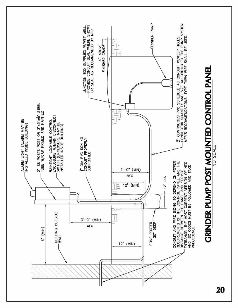


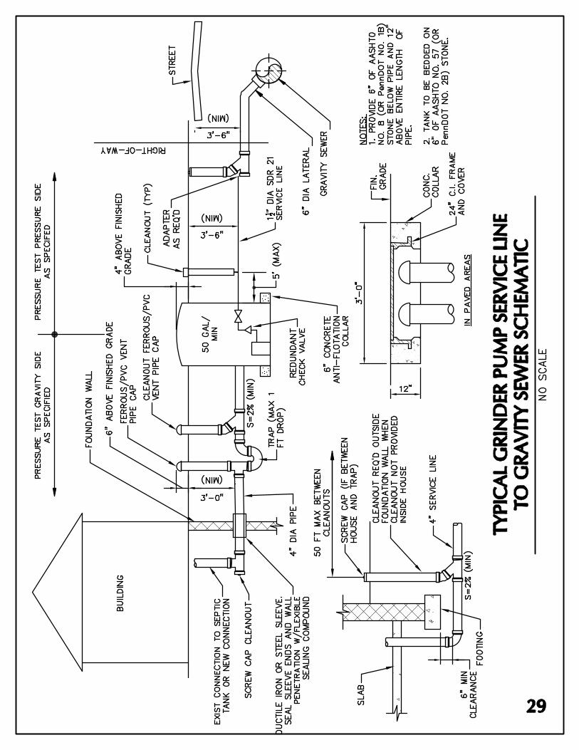


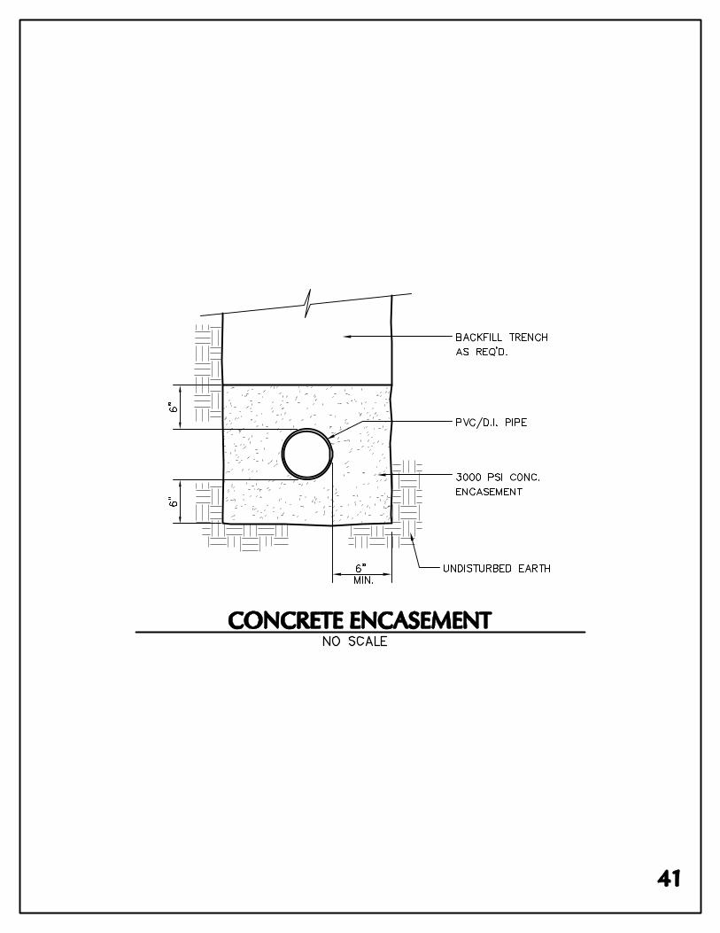

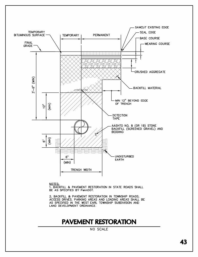

June 2011 C-1
APPENDIX C
INDIVIDUAL GRINDER PUMP MANAGEMENT PLAN
The guidance contained herein is the management plan for residential individual grinder pumps and low-pressure sewer systems to be utilized in the West Earl Sewer Authority service area. This plan does not apply to non-residential grinder pump installations.
A. Low Pressure Sewer Systems
1. The use of individual grinder pumps will be reviewed on a case-by-case basis by the Authority. Where gravity sewer systems are deemed feasible by the Authority, low pressure sewer systems will not be approved.
2. Where deemed appropriate by the Authority, low pressure sewer systems may be installed by a property owner or developer upon Authority approval.
3. When a low pressure sewer system is proposed by a developer, sufficient information must be submitted to the Authority to permit a thorough evaluation of the proposed system. This information shall include, but not be limited to, the following:
a. A detailed explanation as to why individual grinder pump units are proposed in lieu of gravity sewers and/or a conventional pumping station.
b. Plans showing the location of the lots to be served by grinder pump systems.
c. Detailed plans of the proposed low pressure sewer system and individual grinder pump systems.
d. Technical specifications for the proposed grinder pump units and low pressure sewer system.
e. Shop drawings must be submitted to the Authority for approval prior to installation of the units.
4. Individual grinder pump systems shall be as specified in Section 7, Part B of the Authority’s Rules and Regulations. The Authority will not consider proposed “or equal” grinder pump units. The developer’s engineer shall review the hydraulic requirements of the application and confirm that use of an Authority specified pump is adequate, or specify an alternative model pump from F.E. Myers Company, Hydromatic, or Barnes that would be adequate. For every grinder pump unit to be installed in a development within the Authority’s service area, the developer shall provide a lump-sum cash payment of $250. In cases where

June 2011 C-2
acceptable grinder pumps, as specified in the Rules and Regulations, are not adequate, the developer or property owner shall provide one spare pump for every fifteen grinder pump units, or fraction thereof, installed.
5. Installation of the grinder pump unit shall be in accordance with the Authority's Rules and Regulations.
6. All low pressure sewer systems and grinder pump installations must be inspected and approved by the Authority or its authorized agent(s) prior to backfilling.
B. Ownership and Maintenance of Facilities
1. All low pressure sewers and service connections located within public roads and sewer rights-of-way shall be dedicated to the Authority in accordance with the Authority’s Rules and Regulations.
2. Maintenance of the low pressure sewers mains shall be performed by the Authority.
3. All individual grinder pump units, controls and service laterals located outside of public road rights-of-way and/or Authority sanitary sewer easements shall be the property of the property owner, regardless of who provides the originally installed equipment.
4. Operation and Maintenance of the grinder pump units, pipes, and all appurtenances and controls located outside of public road rights-of-way and Authority sewer easements will be the sole responsibility of the property owner. All charges for operation and maintenance of the grinder pumping system, including, but not limited to electric charges shall be the responsibility of the property owner. Electricity charges shall be part of the monthly sewer user fees and paid by the property owner for those properties that are not serviced with electricity.
5. Should a maintenance problem develop, the property owner should contact a plumber to make the required repairs. If, in the course of making the repairs, the plumber finds that a replacement pump is needed, the plumber will be able to acquire an available pump from the Authority until such time that the plumber can purchase a new pump from a supplier.
6. All control panels for individual grinder pump units shall have a permanently attached phenolic label indicating that “All maintenance costs for grinder pump systems are the property owner’s responsibility. For service, contact your plumber.

June 2011 C-3
7. The following note shall be included on all development plans proposing the use of grinder pump systems in the Authority’s service area:
“A copy of West Earl Sewer Authority’s Individual Grinder Pump Management Plan shall be given to the owner of any affected property at the time of settlement on that property.”
C. Grinder Pump Policy
In accordance with the requirements of the Pennsylvania Department of Environmental Protection (PADEP), the Authority provides spare grinder pumps for residential customers of the Authority’s sewerage system.
The following policy shall apply to the acquisition of the spare grinder pump units:
1. Recipient shall be a customer of the Authority with an approved grinder pump
connection to the Authority’s sewerage system. Recipient may also be a designated agent for a qualified customer (i.e.: plumber).
2. The plumber shall contact the Authority at the West Earl Township building at
157 West Metzler Road, Brownstown, PA during normal business hours, or by calling 717-859-3201 after hours.
3. When the repaired pump has been returned to the Authority, it will be put back
into stock.
4. All repair costs of the grinder pump will be the responsibility of the property owner.
D. Grinder Pumps under Warranty
1. It is the policy of the Authority that any warranty problems associated with the individual grinder pumps and appurtenances should be handled directly between the property owner and the Authority. All costs to remove and replace the pump shall be the homeowner’s responsibility.

WEST EARL SEWER AUTHORITY
GRINDER PUMP ADMINISTRATION FORM Homeowner Information:
Name:
Mailing Address:
Telephone No.:
Property Information:
Property Street Address:
Resident’s Name (if different from Owner):
Telephone No. (if different from Owner):
Replacement Pump Information:
Date:
Pump Make and Model No.:
Pump Serial No.:
Pump Issued By: (Authority Representative)
Original Pump Information:
Date Returned:
Pump Make and Model No.:
Pump Serial No.:
Received By:
I hereby acknowledge awareness of the requirements of the West Earl Sewer Authority’s Grinder Pump Policy and agree to comply with those requirements.
Accepted By:
Date: Plumber’s Signature (or agent)